USER MANUAL MXA5000 YAMAHA
Read the supplied booklet "Safety Brochure" before using the unit.
Install the unit in a well ventilated, cool, dry, clean place - away from direct sunlight, heat sources, vibration, dust, moisture, and/or cold. Allow ventilation space of at least 30~cm (11-3/4") on the top, 20 cm (7-7/8") on the left and right, and 20 cm (7-7/8") on the back of the unit.
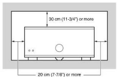
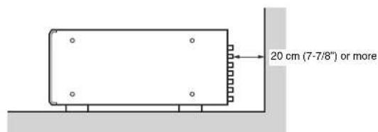
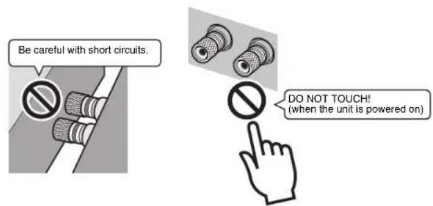
Since the unit adopts bare metallic speaker terminals, make sure keeping enough space on the back of the unit. If the speaker terminals come into contact with metal parts of the AV rack, etc., the unit will be shortened and damaged. Also, never touch the speaker terminals when the unit is powered on since it may cause an electrical shock.
The unit does not have volume controls. Make sure you connect a device with volume control (such as a pre-amplifier) to the unit. If you connect a device without volume control (such as a CD player) directly to the unit, the volume may become excessively loud and result in damage to the unit or speakers.
CONTENTS
Precaution for use
Accessories 1
Features 2
Part names and functions 3
Front panel 3
Rear panel 4
Connections 6
Connecting speakers 7
Connecting the power cable 8
Turning on/off the unit 8
Other functions 8
Turning off the unit automatically (auto-standby function) 8
Dimming the power indicator 8
Turning on the unit in conjunction with operating other devices (trigger function) 9
Advanced speaker configuration 10
Using a speaker that supports bi-amp connection 10
Using two pairs of front speakers (SPEAKERS A/B) 10
Using three speakers for one channel (multi-speaker) 10
Appendix 11
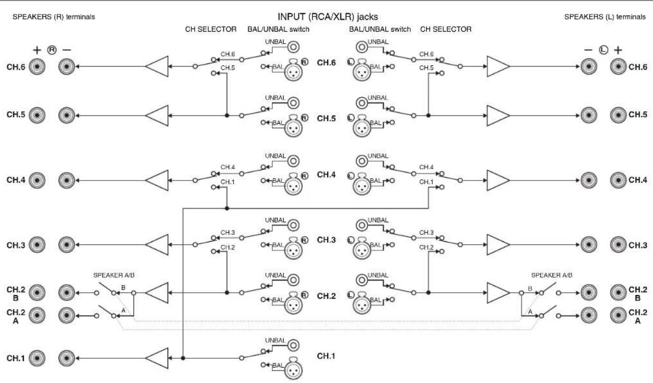
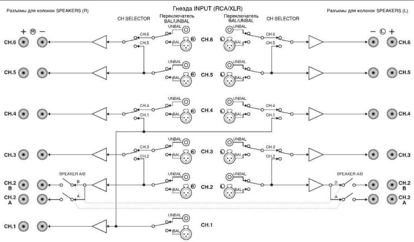
Input-output signal path diagram 11
Troubleshooting 12
Specifications 13
Accessories
Check that the following accessories are supplied with the product.
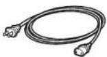
Power cable

The supplied power cable varies depending on the region of purchase.
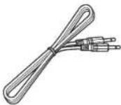
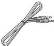
System control cable

Owner's Manual
- Due to product improvements, specifications and appearance are subject to change without notice.

tes precautions for use of the unit and its feature limitations.

tes supplementary explanations for better use.
Features
High-quality power amplifier
■High output/high audio-quality amplifier (150 W x 11 channels)
The unit provides an 11-channel power amplifier featuring a three-stage Darlington current feedback circuit, with a power supply that uses the same type of toroidal transformer used in top-level hi-fi audio devices. The gold-plated speaker connectors are also of the highest quality, delivering high-grade sound.
Balance and unbalanced connections are supported
Balanced (XLR) and unbalanced (RCA) input jacks are provided on all channels, and can be selected independently for each channel.
Balanced connections minimize the extraneous noise that can arise in the cable connection between the unit and the pre-amplifier, ensuring high-fidelity transmission of the audio signal.
Unbalanced connections utilize ground-sensing to achieve fidelity that is close to balanced transmission.
The chassis features a special structure that allows the full potential of the high-quality power amplifier's potential to be revealed.
- Symmetrical power amplifier design
Aluminum front panel and side panels
- Extremely stable feet utilizing the A.R.T. (Anti-Resonance Technology)
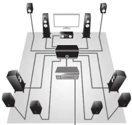
Expandable to meet diverse needs
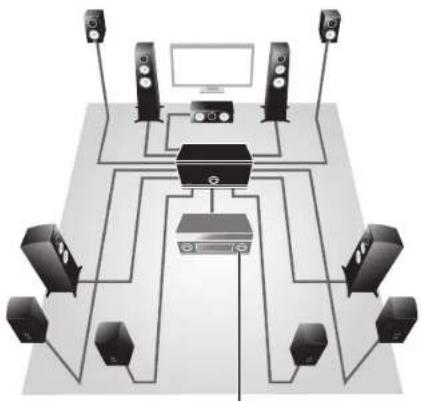
■Freedom for speaker placement
Since power amplifiers of the identical specification are provided for all 11 channels, you use the unit not only for constructing a home theater setup of up to 11 channels but also for multi-room systems or any other speaker configuration to meet your needs.
Pre-amplifier
Support for bi-amp connections and multi-speaker playback
The unit provides a channel selector function that lets you utilize bi-amp connections or multi-speaker connections without having to connect additional cables from your pre-amplifier. For example, the CH.2 audio input could be output from both the CH.2 and CH.3 speaker outputs to drive a bi-amp configuration for high-quality sound, or the CH.1 (monaural) input could be output from three speakers connected to CH.1 and CH.4 (L/R).
Switch the unit's power from your pre-amplifier (trigger function)
The unit can switch its own power status in synchronization with power switching operations on another device that supports the trigger function, such as an AV pre-amplifier (TRIGGER IN). The input signal from the TRIGGER IN jack can also be output without change in a cascade connection to switch the power of another device such as a Yamaha subwoofer (THROUGH OUT). In addition, another device can be switched in synchronization when the power of the unit is switched (TRIGGER OUT), allowing you to set up a variety of systems with synchronized power switching.
Part names and functions
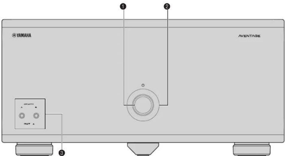
Front panel
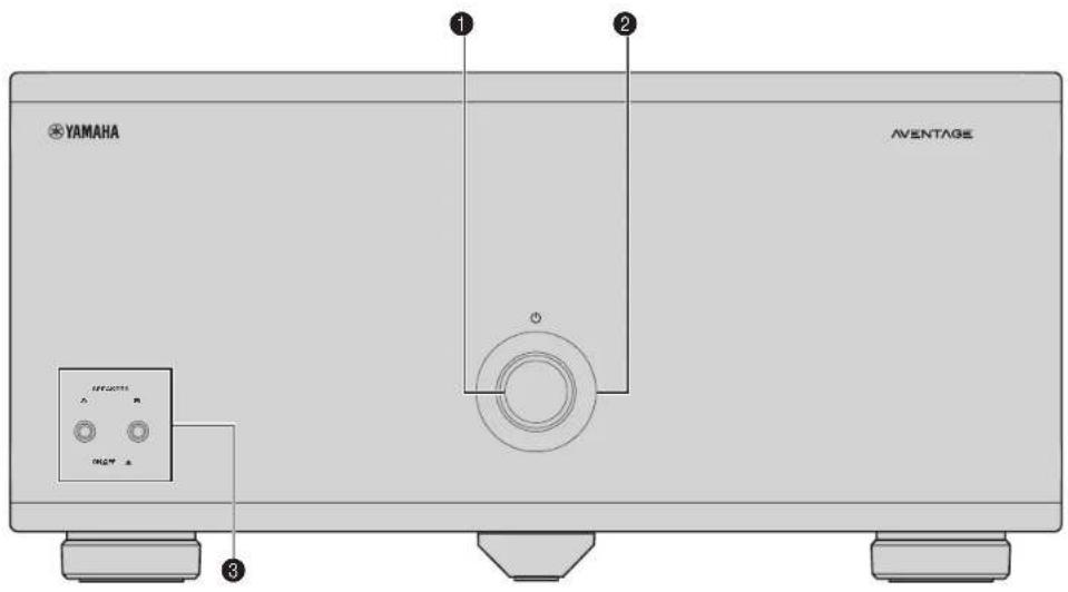
(0) (power) key
Turns on/off (standby) the unit (p.8).
Power Indicator
Lights up when the unit is turned on.
If the indicator blinks, the protection circuitry has been activated. For details, see "Troubleshooting" (p.12).

- You can dim the power indicator (p.8).
SPEAKERS A/B keys
Turns on/off the speakers connected to the CH.2 A/B
terminals (p. 10)

Both the speakers (A and B) are turned off by default. Press the key to turn on the speakers you want to use.
- When using two pairs of the speakers connected to the CH2 A/B terminals at the same time, be sure to use 8-ohm speakers and set IMPEDANCE SELECTOR to the upper position (p.7).
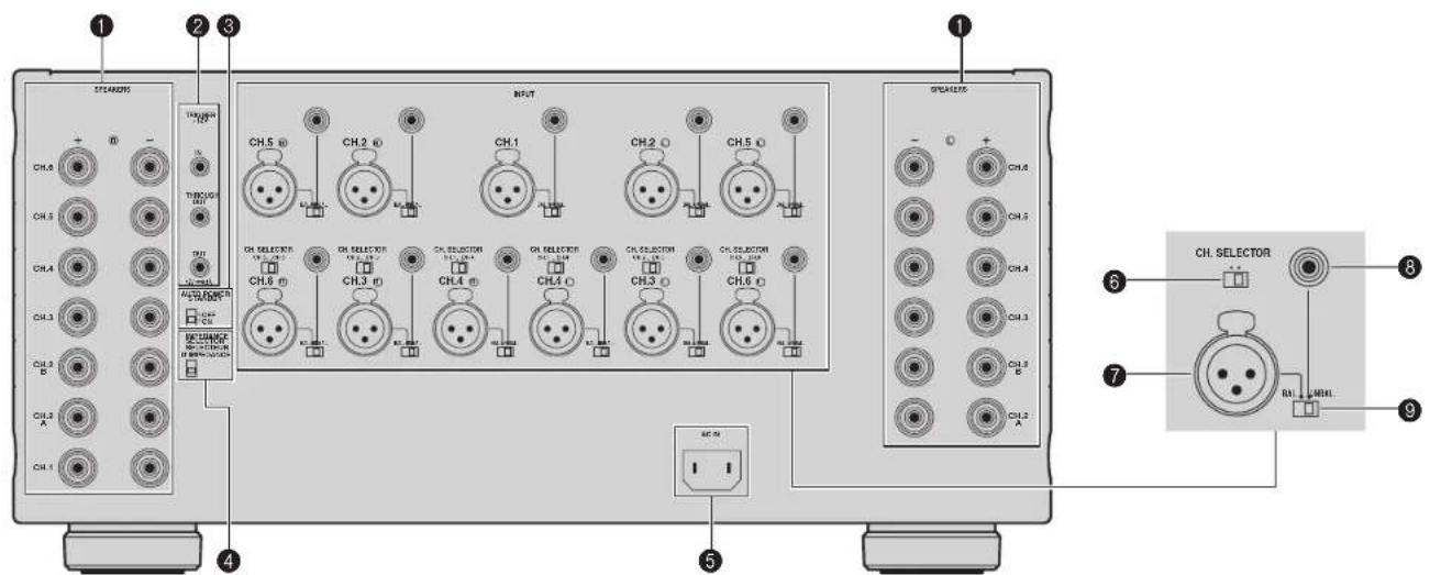
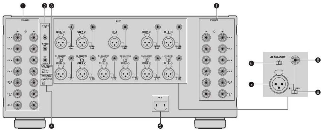
Rear panel
Caution
- Remove the unit's power cable from an AC wall outlet before making any connections or operating the switches and/or selectors.
SPEAKERS terminals
For connecting to speakers (p.7).
TRIGGERJacks
For connecting to devices that support the trigger function (p.9).
AUTO POWER STANDBY switch
Enables/disables the auto-standby function (p.8).
IMPEDANCE SELECTOR
Changes the unit's speaker impedance setting depending on the speakers connected (p.7).
AC IN jack
For connecting the supplied power cable (p.8)
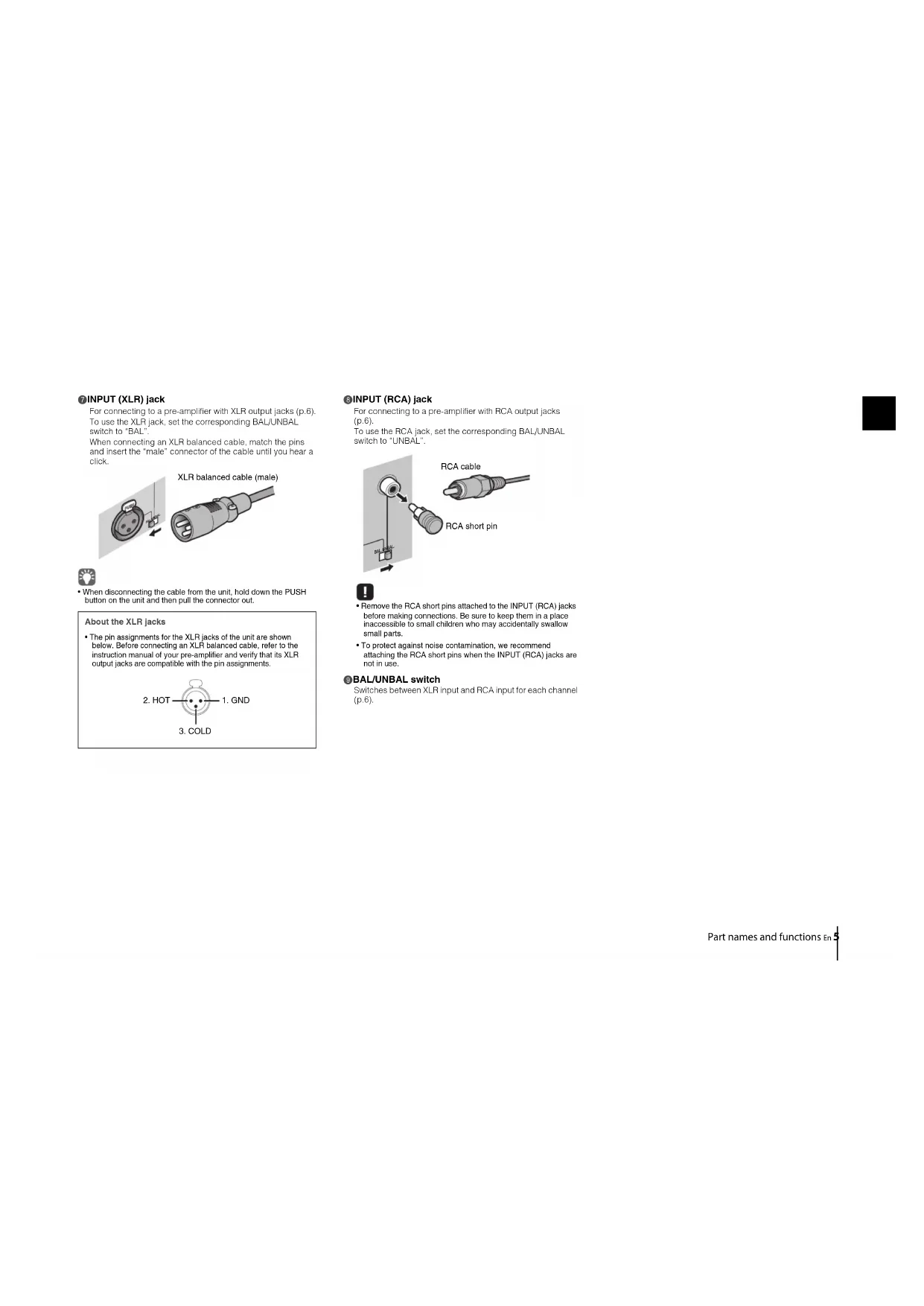
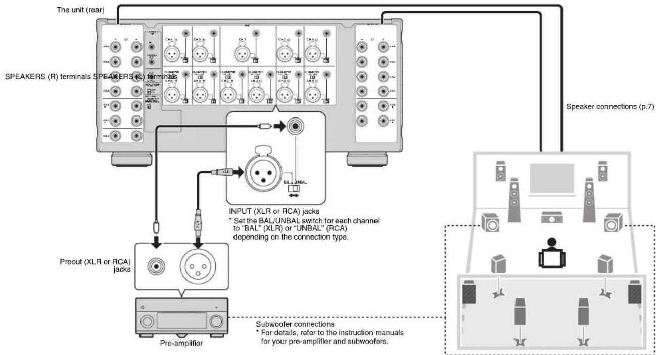
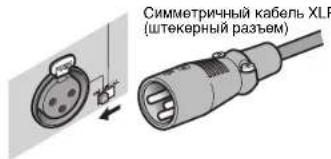
For connecting to a pre-amplifier with XLR output jacks (p.6). To use the XLR jack, set the corresponding BAL/UNBAL switch to "BAL".
When connecting an XLR balanced cable, match the pins and insert the "male" connector of the cable until you near a click.
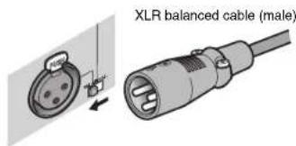

- When disconnecting the cable from the unit, hold down the PUSH button on the unit and then pull the connector out.
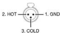
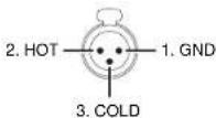
About the XLR Jacks
- The pin assignments for the XLR Jacks of the unit are shown below. Before connecting an XLR balanced cable, refer to the instruction manual of your pre-amplifier and verify that its XLR output Jacks are compatible with the pin assignments.
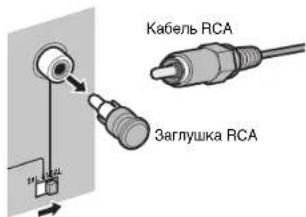
For connecting to a pre-amplifier with RCA output Jacks (p.6). To use the RCA jack, set the corresponding BAL/UNBAL switch to "UNBAL".
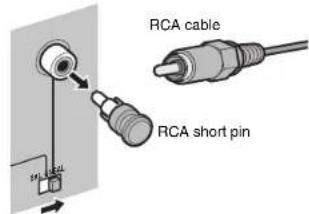

- Remove the RCA short pins attached to the INPUT (RCA) jacks before making connections. Be sure to keep them in a place inaccessible to small children who may accidentally swallow small parts.
- To protect against noise contamination, we recommend attaching the RCA short pins when the INPUT (RCA) jacks are not in use.
BAL/UNBAL switch
Switches between XLR input and RCA input for each channel (p.6).
Connections
Caution
- Remove the unit's power cable from an AC wall outlet before making any connections or operating the switches and/or selectors.
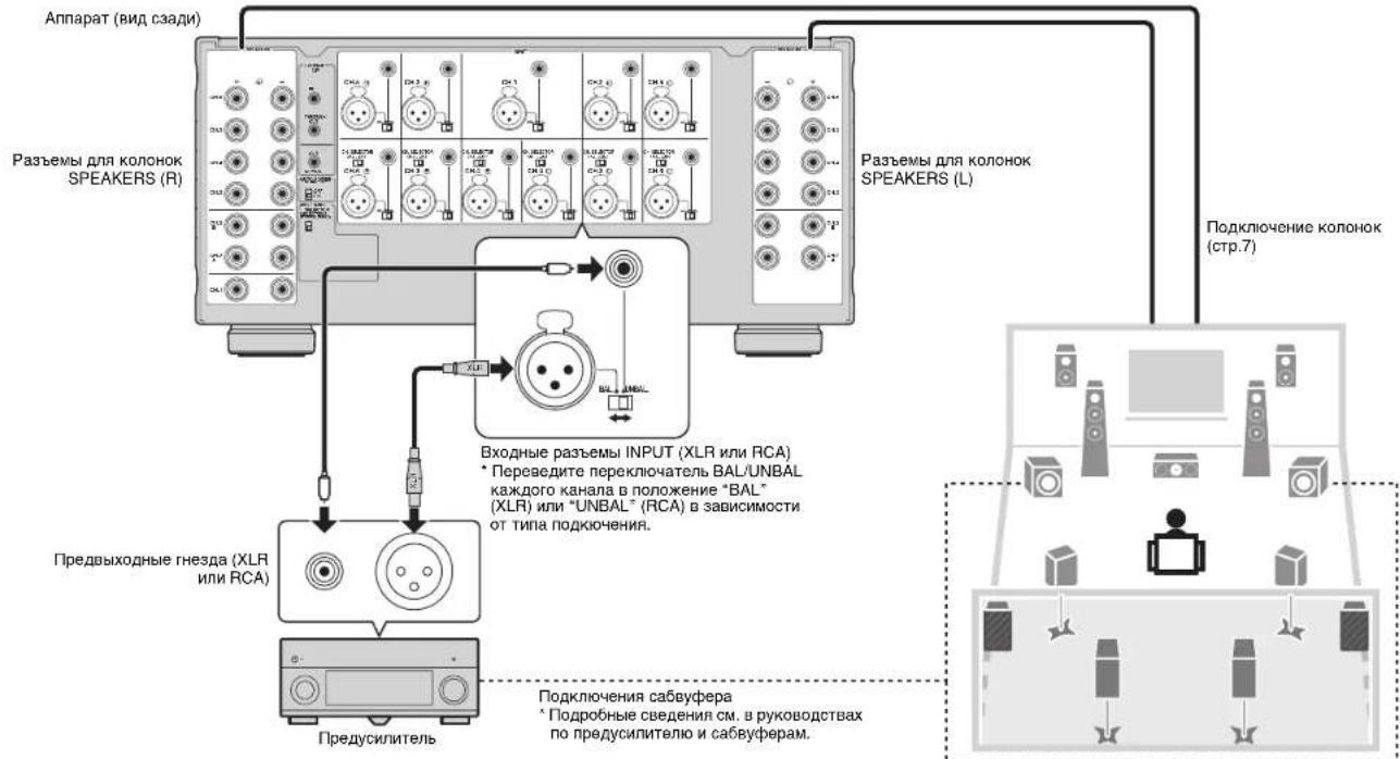
Connect a pre-amplifier and speakers to the unit.
To connect a pre-amplifier, use an XLR balanced cable (for balanced connection) or an RCA unbalanced cable (for unbalanced connection) for each channel depending on the output jacks available on your pre-amplifier.
Connecting speakers
■Note on the speaker impedance
The unit supports the following speaker impedance.
CH.2 A/B: 4 Ω or more (8 Ω or more when using CH.2 A and CH.2 B at the same time)
Other channels: 6 Ω or more
Set the IMPEDANCE SELECTOR to the upper/lower position depending on the speakers connected to the unit.
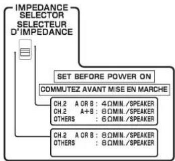
| Upper position | Select this option when your speaker system meets one of the followings.
·When connecting speakers with impedance of less than 8 Ω (4 Ω or more) to the CH.2 A or CH.2 B terminal
·When using two pairs of speakers connected to the CH.2 A/B terminals at the same time (be sure to use 8-ohm speakers for both CH.2 A and CH.2 B)
·When connecting speakers with impedance of less than 8 Ω (6 Ω or more) to speaker terminals other than CH.2 A or CH.2 B |
| Lower position (default) | Select this option when using speakers with impedance of 8 Ω or more only. |
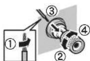
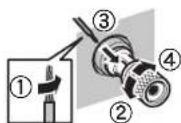
Connecting speaker cables
Speaker cables have two wires. One is for connecting the negative (-) terminal of the unit and the speaker, and the other is for the positive (+) terminal. If the wires are colored to prevent confusion, connect the black wire to the negative and the other wire to the positive terminal.
① Remove approximately 10 mm (0.40 in) of insulation from the ends of the speaker cable, and twist the bare wires of the cable firmly together.
②Loosen the speaker terminal.
③ Insert the bare wires of the cable into the gap on the side (upper left or bottom right) of the terminal.
④ Tighten the terminal.
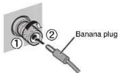
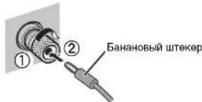
Using a banana plug
(U.S.A., Canada, China, Taiwan and Australia models only)
① Tighten the speaker terminal.
②Insert a banana plug into the end of the terminal.
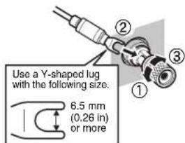
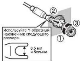
Using a Y-shaped lug connector
①Loosen the speaker terminal.
② Insert the Y-shaped lug connector into the groove between the knob and base part of the terminal.
③ Tighten the terminal.
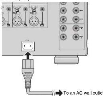
Connecting the power cable
After all the connections and switch operations are complete, connect the supplied power cable to the unit and then to an AC wall outlet.
The unit (rear)
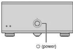
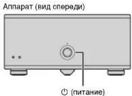
Turning on/off the unit
Press (power) to turn on/off the unit.
When the unit is turned on, the power indicator lights up.
The unit (front)

- When an external device is connected to the TRIGGER IN jack, the unit is set to standby mode after (O) power is pressed. If you turn on the external device, the unit automatically turns on by the trigger function (p.9).
Other functions
Turning off the unit automatically (auto-standby function)
The unit will automatically go into standby mode 8 hours after the unit is turned on. To disable the auto-standby function, set the AUTO POWER STANDBY switch to "OFF".


The auto-standby function works even if playback is ongoing.
- When the system control cable is connected to the TRIGGER IN jack, the auto-standby function does not work even if it is enabled.
Dimming the power indicator
You can dim the power indicator on the front panel of the unit.

- When an external device is connected to the TRIGGER IN jack, turn on it before performing the following procedure.
① If the unit is turned on, press (power) to turn off it.
② Press 日 (power) three times within 3 seconds.
The power indicator dims.

To cancel the dimmer, perform the procedure again.
If the power cable is unplugged, the dimmer will be canceled.
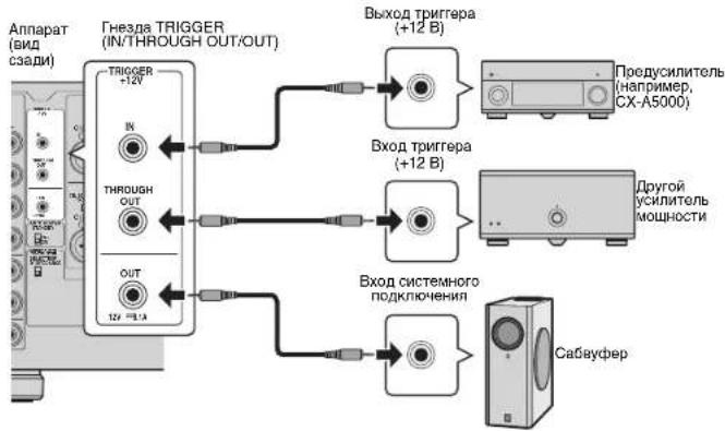
Turning on the unit in conjunction with operating other devices (trigger function)
The trigger function can control power of the unit in conjunction with operating other devices or control power of other devices in conjunction with turning on/off the unit. If you have a power amplifier or a Yamaha subwoofer that supports the trigger function, you can use the trigger function by connecting your devices to the TRIGGER JACKS with the supplied system control cable.
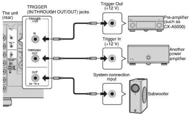
Depending on the intended use, connect your device to one of the following TRIGGER jacks.
IN jack:
For connecting a device that supports the trigger output function (such as a pre-amplifier).
If you turn on/off your device, the unit will automatically turns on/off (standby).

This function is available only when (power) of the unit is on (pressed down).
THROUGH OUT Jack:
This jack outputs signals input from the IN jack.
If you connect a device that supports the trigger input function (such as another power amplifier), your device will automatically turn on/off in conjunction with turning on/off the device connected to the IN jack.
OUT jack:
For connecting a device that supports the trigger input function (such as a subwoofer).
If you turn on/off (standby) the unit, your device will automatically turns on/off.

- To connect multiple devices to the TRIGGER jacks, you need to prepare commercially-available monaural mini-plug cables.
Advanced speaker configuration
Caution
- Remove the unit's power cable from an AC wall outlet before making any connections or operating the switches.
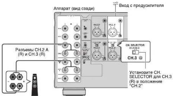
Using a speaker that supports bi-amp connection
If you want to use a speaker that supports bi-amp connection to have more high-quality sounds, change the CH. SELECTOR setting and connect the speaker to the corresponding pair of the SPEAKERS terminals.
(Example)
Using a speaker that supports bi-amp connection for CH.2 (R)
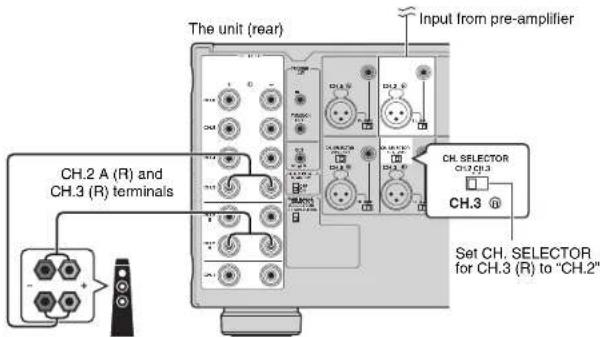
By setting the CH. SELECTOR for CH.3 (R) to "CH.2", CH.2 (R) input signals are output from both the CH.2 (R) and CH.3 (R) speaker terminals. In this case, CH.3 (R) input is not used.
Caution
- Before making bi-amp connections, remove any brackets or cables that connect a woofer with a tweezer. Refer to the instruction manual of the speakers for details. If you are not making bi-amp connections, make sure that the brackets or cables are connected before connecting the speaker cables.
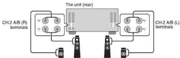
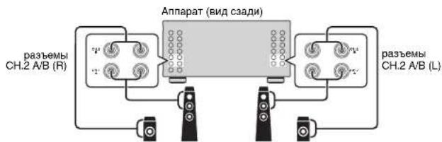
Using two pairs of front speakers (SPEAKERS A/B)
If you connect two pairs of front speakers to the CH.2 A/B terminals, you can switch the front speakers to be used by pressing SPEAKERS A/B on the front panel of the unit.

- When using two pairs of the speakers connected to the CH.2 A/B terminals at the same time, be sure to use 8-ohm speakers and sell IMPEDANCE SELECTOR to the upper position (p.7).
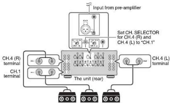
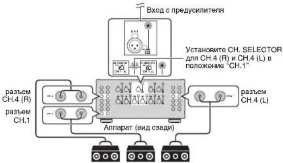
Using three speakers for one channel (multi-speaker)
If you want to use three speakers for reproducing CH.1 audio signals (such as center channel signals), change the CH. SELECTOR setting and connect the speakers to the CH.1 and CH.4 (L/R) terminals.
Appendix
Troubleshooting
Refer to the table below when the unit does not function properly.
If the problem you are experiencing is not listed below or if the instructions below do not help, turn off the unit, disconnect the power cable, and contact the nearest authorized Yamaha dealer or service center.
First, check the followings:
① The power cables of the unit and other devices (such as a pre-amplifier) are connected to AC wall outlets securely.
② The unit and other devices (such as a pre-amplifier) are turned on.
③ The connectors of each cable are securely inserted in to jacks on each device.
| Problem Cause Remedy | | |
| The power does not turn on. | The protection circuitry has been activated three times consecutively. When the unit is in this condition, the power indicator on the unit blinks. | As a safety precaution, capability to turn on the power is disabled. Contact your nearest Yamaha dealer or service center to request repair. |
| The internal microcomputer has frozen, due to an external electric shock (such as lightning or excessive static electricity) or to a drop in the power supply voltage. | Disconnect the power cable from the AC wall outlet and plug it again. |
| An external device is connected to the TRIGGER (IN) jack. | Press down Ⓒ (power) on the unit and then turn on the external device. |
| The power turns off (standby mode) immediately. | The unit was turned on while a speaker cable was shorted. | Twist the bare wires of each speaker cable firmly and reconnect to the unit and speakers (p.7). |
| The unit was shorted because the speaker terminals come into contact with metal parts of the AV rack, etc. | Keep enough space on the back of the unit (p.i). |
| The unit enters standby mode automatically. | The auto-standby function worked. | To disable the auto-standby function, set the AUTO POWER STANDBY switch to "OFF" (p.8). |
| The protection circuitry has been activated because the volume of the external device connected to the unit is too high. | Turn down the volume of the external device. |
| The protection circuitry has been activated because the temperature inside of the unit is too high. | Install the unit in a wall ventilated, place and allow enough ventilation space around the unit (p.i). |
| No sound. | The BAL/UNBAL switch setting is not correct. | Change the BAL/UNBAL switch setting so that it matches the connections (p.6). |
| No sound is coming from a specific speaker. | The speakers connected to the CH.2 A/B terminals are turned off. | Close SPEAKERS A/B to turn on the speakers (p.10). |
| The XLR balanced cable (or RCA unbalanced cable) connecting the unit and pre-amplifier is defective, or the speaker cable connecting the unit and speaker is defective. | If there is no problem with the connection, replace with another cable. |
| Another channel sound is coming from a specific speaker. | The CH SELECTOR setting is not correct. | Change the CH SELECTOR setting so that it matches your speaker system (p.10). |
Specifications
Audio
Analog RCA (Unbalance) x 11
Analog XLR (Balance) x 11 (1:GND, 2:HOT, 3:COLD)
Output jacks
Speaker Out x 11 ch
(13 Terminals: CH.1, CH.2-A [L/R], CH.2-B [L/R], CH.3 [L/R] to
CH.6 [L]
Other jacks
- TRIGGER OUT x 1 (+12 V/0.1 A max.)
- TRIGGER IN x 1 (+12 V In)
- TRIGGER THROUGH OUT x 1
Audio Section
- Rated Output Power (2-channel driven)
(20 Hz to 20 kHz, 0.08% THD, 6 Ω)
CH.1 170W
CH.2 (L/R) 170 W
CH.3 (L/R) 170 W
CH.4 (L/R) 170 W
CH.5 (L/R) 170 W
CH.6 (L/R) 170W
(20 Hz to 20 kHz, 0.06% THD, 8Ω)
CH.1 150W
CH.2(L/R) 150W
CH.3 (L/R) 150 W
CH.4 (L/R) 150 W
CH.5 (L/R) 150 W
CH.6(L/R) 150W
(1kHZ.0.9%THD,8Ω)
CH.1 170W
CH.2 (L/R) 170 W
CH.3 (L/R) 170 W
CH.4 (L/R) 170 W
CH.5 (L/R) 170 W
CH.6 (L/R) 170 W
Rated Output Power (1-channel driven)
(1kHz,0.9%THD,6Ω)
CH.1 230Wch
CH.2(L/R) 230 W/ch
CH.3 (L/R) 230 W/ch
CH.4 (L/R) 230 W/ch
CH.5 (L/R) 230 W/ch
CH.6 (L/R) 230 W/ch
(1kHZ0.9%THD,8Ω)
CH.1 190 W/ch
CH.2 (L/R) 190 W/ch
CH.3 (L/R) 190 W/ch
CH.4 (L/R) 190 W/ch
CH.5 (L/R) 190 W/ch
CH.6 (L/R) 190 W/ch
(1kHZ.09%THD,4Ω)
CH.2 (L/R) [U.K. and Europe models] 290 W/ch
Maximum Effective Output Power (1-channel driven, JEITA)
[China, Taiwan, Korea and Asia models]
(1kHz, 10% THD, 6Ω)
CH.1 280 W/ch
CH.2 (L/R) 280 W/CH
CH.3 (L/R) 280 W/ch
CH.4 (L/R) 280 W/ch
CH.5 (L/R) 280 W/
CH.6 (L/R) 280 W/ch
(1 kHz, 10% THD, 8Ω)
CH.1 230 W/ch
CH.2 (L/R) 230 W/ch
CH.3 (L/R) 230 W/
CH.4 (L/R) 230 W/ch
CH.5 (L/R) 230 W/ch
CH.6 (L/R) 230 W/ch
-
Dynamic Power (IHF)
1-channel driven (8/6/4/2 Ω) 190/250/350/500 W
Damping Factor
All Channels, 1 kHz, 8Ω 180 or more
-
Input Sensitivity / Input Impedance
Unbalance (1 kHz, 100 W/8 Ω) 1.0 V/47 kΩ
Balance (1 kHz, 100 W/8 Ω) 2.0 V/47 kΩ
Maximum Input Signal
Unbalance (1 kHz, 0.5% THD, 8 Ω) 1.3 V or more
Balance (1 kHz, 0.5% THD, 8 Ω) 2.6 V or more
Frequency Response (10 Hz to 100 kHz) +0/-3 dB
Total Harmonic Distortion (70 W/8Ω) 0.015% or less
- Signal to Noise Ratio (IHF-A Network)
(Input Shorted 1kΩ, Reference Level 150 W/8Ω)
176 dB or more
Residual Noise (HF-A Network)
Speaker Out (Input Shorted). 60 V or less
- Channel Separation (Input 5.1 kΩ Shorted, 1 kHz/10 kHz)
9075 dB or more
Gain 29.1 dB
General
Power Supply
[U.S.A.and Canada models]AC 120 V,60 Hz
[Taiwan model]. AC 110 to 120 V, 50/60 Hz
[China model] AC 220 V, 50 Hz
[Korea model] AC 220 V, 60 Hz
[Australia model] AC 240 V, 50 Hz
[O.K.and Europe models] AC 230 V,50 Hz
[Asia model].AC 220 to 240 V, 50/60 Hz
Power Consumption
[U.S.A.and Canada models] 650 W/650 VA
[Korea model] 550W
[Other models] 650 W
435x210x463.5mm(17-1/8"×8-1/4"×18-1/8")
*Including legs and protrusions
Weight 25.4 kg (56.0 lbs)
* Specifications are subject to change without notice.
Bouton (allimentation)
(1 kHz, 0.9% THD, 8Ω)
CH.1 170W
CH.2 (L/R) 170 W
CH.3 (L/R) 170 W
CH.4 (L/R) 170W
CH.5 (L/R) 170W
CH.6(L/R) 170W
CH.4 (L/R) 190 W/voi
CH.5 (L/R) 190 W/voie
CH.6 (L/R) 190 W/voie
(1kHz,0.9%THD,4Ω)
CH.4 (L/R) 280 W/voiO
CH.5 (L/R) 280 W/voie
CH.6 (L/R) 280 W/voie
(1kHz, 10% THD, 8Ω)
CH.1 230 W/vo
CH.2 (L/R) 230 W/voie
CH.3 (L/R) 230 W/voie
CH.4 (L/R) 230 W/voie
CH.5 (L/R) 230 W/voie
CH.6 (L/R) 230 W/voie
1 vole (8/6/4/2 Ω) 190/250/350/500 W
Taux d'amortissoment
Asymétrico (1 kHz, 100 W/8 Ω) 1,0 V/47 kΩ
Symétrie (1 kHz, 100 W/8 Ω) 2,0 V/47 kΩ
Distorsion harmonique totale (70 W/8Ω)....0.015% maximum
1 kHz/10 kHz) 90/75 dB minimum
Gain. 29,1 dB
Généralités
Alimentation
RCA analogico (sin balancer) x 11
XLR analogico (balanceado) × 11 1:TIERRA,2:ACTIVO, 3: PASIVO
Tomas de salute
Audio
CH.1 170W
CH.2 (L/R) 170 W
CH.3 (L/R). 170 W
CH.4 (L/R) 170 W
CH.5 (L/R) 170 W
CH.6(L/R) 170W
(dc20Hza20kHz,0.06%THD,8Ω)
CH.1 150W
CH.2(L/R) 150W
CH.3 (L/R) 150 W
CH.4 (L/R) 150 W
CH.5 (L/R) 150 W
CH.6 (L/R) 150 W
(1kHz,0.9%THD,8Ω)
CH.1 170W
CH.2 (L/R) 170 W
CH.3 (L/R) 170 W
CH.4 (L/R) 170 W
CH.5 (L/R) 170 W
CH.6 (L/R) 170 W
CH.2(L/R) 230 W/canal
CH.3 (L/R) 230 W/canal
CH.4 (L/R) 230 W/canal
CH.5 (L/R) 230 W/canal
CH.6 (L/R) 230 W/canal
(1kHz,0.9%THD,8Ω)
CH.1 190 W/canal
CH.2 (L/R) 190 W/canal
CH.3 (L/R) 190 W/canal
CH.4 (L/R) 190 W/anal
CH.5 (L/R) 190 W/canal
CH.6 (L/R) 190 W/canal
(1kHz,0.9% THD,4Ω)
CH.2 (L/R) [Modelos del R.U. y Europa] 290 W/canal
(1 kHz, 10% THD, 6Ω)
CH.1 280 W/canal
CH.2 (L/R) 280 W/canal
CH.3 (L/R) 280 W/canal
CH.4 (L/R) 280 W/canal
CH.5 (L/R) 280 W/anal
CH.6 (L/R) 280 W/canal
(1 kHz, 10% THD, 8Ω)
CH.1 230 Wicanal
CH.2(L/R) 230 W/canal
CH.3 (L/R) 230 W/canal
CH.4 (L/R) 230 W/canal
CH.5 (L/R) 230 W/canal
CH.6 (L/R) 230 W/canal
Balanceado (1 kHz, 100 W/8 Ω) 2,0 V/47 kΩ
Bknoyehn HbKnoyehne annapara 8
Ipouee yHKmnn 8
ABTOMATMueckoe BbIKIOeHne annapata (dyHKnA ABTOMATMueckoro nepexoda
BpeKIM OXnDaHn8
OcnabneHnncBeta HndkaTopa nHTAHNA 8
BknueHne annapata Bmte np pa6ote pynx yctpoiCTB (yHKnna Tprrrepa) 9
PacunepHHa KOnHpyauqna KonoHok 10
Ncnonb3OBAHnK KOONHn, NOdepknaBaOouen NOKIOHeHm C DByXKaHaJIbHbIM yCUNHeHem 10
Icnonb3obaaHne DByx nap pOHTaBbIX KOHOK (SPEAKERS A/B) 10
IcnoNb3oBaHne Tpex KonoHok dna OJHOra KaHaHa (HeckoKko KonoHok) 10
PpuloxeHne 11
Cxema npoxoeknBxOaHux/ncxoHnn CmHanOB 11
PonckyucpaHHe HeuCpBHOCTe 12
Texnueckx xapaKrepcntk 13
PpHaJdxKHOCTN
Y6eIeBc,TOB KOMNIeK NToCABKn I3dEIN BxOaIT CNEyIOme PnHAdNKeXHO.
CnnoBouKa6eB
NoctaennnnaenbKaebnntaanrnnnrrnannrnrnnrnrnnrnrnnn
CnCTeMHbIKoHTpOJIbHbI Ka6eJIb
HCTpyKUNna no 3Knnyataaun

BpesyIATEyOuebpeHCTBOBAHINJNEDAIYTeXHHECKMEXapakTePCHNTKNMHBEHNHHBMANAPARATQMYT NEMEHTRC6BSEyDMONHEK
BBAET HMEbI PpeOCTOPOKHOCTN pni HCNOb3OBaHn annapata NOrpaHnHnEraEO FyHKm.
MkBaet Ha donoHnHteBHe IeHCTpyuMoNo oTmAlbHMy HcNtIbSobAHHo.
OncaHne
BbICOKoKaueCTBeHHbI yCUNITeNb MoHOCn
MoUhbi, BbICOKKaueCTBeHHbI yCnInTeJb (150Bx11kaHaoB)
Annapa IMeet 1-KahanBhI yCINInTeIb MoUHcTn, OchauEnHbI TpExCTyENHATbIM KOHTypOM o6paTHoN CB3N NO TokY Darlington C 5NOKOM TINAHN, KOTOpB I NcONbEyETOT XE TIN TOPOJaB HOrO TpaHCxOpMaTopa, KOTOpB I NcONb3yETCB B BICOKOYPOBHBEx ayIOYCTPOCTbXaHi-fI. POkBtIe 30TONOT BBICOKOKaCeCTBHNbIe pa3bEMbl KOHOHOK TAKKcO6ecNEuBaKoT BcYuaHne CamORO BbcKcOReO YPOBBH.
IpoJepKnBAOTcKaK CmmMeTpNHybI, TaK I
HecMMMeTpUHbIe CoeUNHeHnA
BxODbIe pa3bEmbl IIN CMMMTePnHbIX (XLR) IN HeCMMMeTPOHbIX (RCA) CoEINHOHN MMIEOTcI IN BCEX KAHANOB MORYT 6bIbTB bIBpaHbI He3aBNCMO DnKAKDOro KAnahA.
CMMMETPNHbIE COeHNHeHHN CHNJIOT BHEINHEIy HJMbI, KOTOpBE MONT BO3HNKHYt Ha KaJIeBbIbS IIO NKNIQHcENHXM NMeKdy anapATOM INpeayniHTeNEm, YTO OBeCNeHMaBT BiBcOKoKaTOM HeCTBENHyO NEpeJaY aUdnoCnHnAoB.
HecMMETPRUHb CoeINHeHHN IcNoIb3yIOt ONpeDeneHye yOBHN oBSe hCteN dN aocTHJeHN HAKeCTBA, CXKERO CcmTnHn HpeNaeAHJ.
KoHCTpykTnBhble 3NeMeHtbl KOpNyca, KOTopbIe N03BONrO TΦeKTHBHO UcNOnb30BaTb BCE B03MOXHOCTn aannapata
KOpNcMMEeKCHOTyKTHMBHbIE 3NEMeHTbI,KOTOpBIE NO3BOJHOIT 3AEDJEBOBAtB BCE BO3MOXHOCTO BbICOKOKAKHECTEHHORO YCJINTEJNO MOUHOCTn.
CMMMeTpuHAn KOHCTpyKUy yCUNHTeN MOUHOCTN
- NueBaHn BOKOBbIe NaHeJIb BbINONHeHbN3 aHOMHHa
OcHb yToHnBnA noCTaBA, noDpeKnBaIOuAa TExHOIrA A.R.T. (aHType30AnHcHaa TeXHOIroMa)
Bo3mOxHocTb paCwipenHn IyDobLeTbOpEHn paCTuux noTpe6HoTei
B03MOxHoctb CBO6oHOropa3MeueHnKoJohOK
Tak KaK yCNHNTEN MOUHOCTN C HeHTNUHBIMn XAPaKTepHCTNKAMn IpeoOCTabNIOTCn DnBCEX11KaHANOB, annapat MOKHO NcNOB30BaT He TOnbKOdHnAePONIK BnOTb 11 KaHANOB nDcBOeroDOMaHIero KINHOTeaTpa, HO n TaKKe BMHOROKOMHaTHbIX CImTeMAx IN HIObIX dpyTNX KOHOFyPAQNA KOLOHOK B3aBNCMOCTN OTnpDeBnREMbEx TpeOBOAHm.
Ppeynntenb
Iopdepkka coeHneHn C DByXKaHaJIbHbIM ycHJeHEm N BOCnpOu3BedeHnEM Ha HeCKoJIbKx KOnOHkax
Annapat npedocabnretyHKNUO CNEKTOPA KaHANOB, KOTOPAR NO3BOLRETNCNLOBtBaTOeDHEHRC BByXKAHAbbIM yCNIOHEHM ENI OCoEINHEHRC HECKoLbKMMN KOLONKAMN Be3 He06XoDMOCTH NpOKiIOHOEHN DOnONIHTeBbHbIX KaBEnK N ppeYcunHTEIO.HanPMep. AynIOHOCH CH.2 MOKeT BBBOIDITCB C BxIOXoBA H KOLOHNCH.2 nCH.3 nJn KOHfNpyaUM DBHAPPABENHORO YCINHEHRA BICCOKOKAeCTBEHORO 3BvAHn, INI BXoD CH.1 (MOHOFOHNHECKM) MOKET BBoIDHTCBaH TPOLOKN, NpDKNOOHHBEK H BxOaDMCH.1 nCH.4 (NT).
BknoueHne nHTaHnna annapata c npeducnntela (fynkunr Tprirrepa)
AnnapaT MoKeT NepeKIOHcTb COCTOHN CBOERO
NITAHNA B COOTBETCTBmC COCTOHN HNTAHNA HA
dpyrOM yCTPOINBE, NOIDEPXnBAoUeM 3Ty 0yHKNUO
TPhIRTEp, HanPIMep HA AV npdyCNITNE (TRIGGER
IN).BxOHDHO CNHcN c pa3bEMa TRIGGER IN TAKKe
MOKeT BBIOBDtCB RAH3M3MeHHbIM NO KACKaHOMY
CoDIIHEHNOI dne nepeKIOHcHNIHTAHNHa DpyROM
ycTPOInTe, HanPIMep Ha cABSyCpeYamaHa
(THROUGH OUT).KpOME TOR,dpyroYcTPOINCTBO
MOKeT 6blTB BKIOUeHO NMI BIKIOUeHO B
COOBETCTBm C COCTOHN MNTAHN ANAPATA
(TRIGGER OUT),TO no3BoNReH NaCTpaMbTa
pa3NNHbIE CnCTeMb C CNHXPOHN3aue BKNIOeHn
BbIKIOUeHN NITAHN.
Ha3BaHmKOMnHOHeTOb mnx yHKuM
PepednnaHelb
Knabuha nHTaHa
BknOHeHbIbnKHeHn (pehXoD B pexim OxNAnHH) annapata (ctp.8).
HndkaTopbI nHTAH
3aropaetc npn BkHIOeHHOM annapaTe.
Ecnn HndkaTOp Mrraet. cxema 3aunTb6bna BKnOHeHa
Плоб Shoebicedemma.Бараздени"ТонкИстанимеНецрарноct"(cpt.12).

- MoXHO OcIaBmTb CHT HnDnKATOp nITAHH (Ctp.8).
Khoonk SPEAKERS A/B
BknOaETnIKOTKNOaETKONOKN, NOkDNIOHHeI K paaEBamC.H2A/B (ctp.10).

-ObE KOHOKA(AuB)No yMOJINAHMO DTKIOHOHb.HAKMMTE KONKYDnBKOHOHARAKOLOHKOTOPbIEcIeYET KOHNO308Ba.
-ПИОнглбогддгдгдгдгдгдгдгдгдгдгдгдгдгдгдгдгдгдгдгдгдгдгдгдгдгдгдгдгдгдгдгдg
-нлкпсьнлсьнлсьнлсьнлсьнлсьнлсьнлсьнлсьнлсьнлсьнлсьнлсьнлсьнлсьнлсьнлсьнлсьнлсьнлсьнлсьнлсьнлсьнлсьнлсьнлсьнlсьнлсьнлсьнлсьнлсьнлсьнлсьнлсьнлсьнлсьнлсьнлсьнлсьнлсьнлсьнлсьнлсьнлсьнлсьнлсьнлсьнлсьнлсьнлсьнлсьнр
-КOLONKH N PEPBDEI TPEPKEKCHATELIMPEDANCE
SELECTOR (CenkekTop COPIPTHINEN) B PEXHNE
nOLONKHE (cpt.7).
3aHnaheb
PpeynpzmdeHne
PepdBnONHHeM NcBExbHnNpAobToC npeKIOHHTAMN INCEOpTOMK3BKEKNTK3HACHHO peHTKPeMHHO10XCAINHOHKnKaEbnAtmnpata.
Pa3bemblnKoJHOHOK SPEAKERS
JIN NOKNOOHMA K KOHKM (cTp.7).
THe3da TRIGGER
IINIOJNOKIOHNEK YCTOPTOBAM,IOIDNEPCKMBAOLOE MyIKNUIO TPITRTEA (ctp.9).
9NepeeknouateNB AUTO POWER STANDBY
BKNIOHHeHbIKIOHHe HpyHKIIN pEXIMa OXINADHMA (ctp.8).
IMPEDANCE SELECTOR
MnHHeR HAcTPOKky COpTOBnEHHa KOnOHKn HA annapate a 3aBcIMoCTM OT NOkIIOueEHbIX KOHOHK (ctp.7).
THe3oACIN
ДиоюдкійчEOHIN NOCTABNREMORO CYNOBOR KABENR (ctp.8).
CH. SELECTOR
(TonbKO CH.3,CH.4 n CH.6)
3noBbaerBbOpBa ayDmocTOCHNk BDOa DnR yCUnInTeRA CH.3,CH.4 nKn CH.6 npri NcNoBcBOAHm NOckNIOChyEeP C bDxKHaHbIh My cUINHeM (ctp.10) mN oN kNOChyEmn C HECKOKBIM KONOHKAm (ctp.10).
JINDAKIOYENH KI PDEYCINNTENIO C BIXOXDHIMPA36MAMXLCRTP.6
Tc0b6nIcno3b8RtB3eO XLR, nepeBede nepneKnoHateB BAL/UNBAL n noJoxene "BAL"
PnpnoDcoaHHeHHn CmmMeTnHOrO KaBn XLR CONCTABTe KOHTAKTIN BCTABTe "WTEKePbH pBa3eM" KaBn Do JIeNHa.

PPIKTNCHHNA KABeIaON aTnapata UdpeKbHaTe RnaKaToH KhoNk PUSH Na anapara, OdoBpeMeHO NsBeNeKa paa3em.
OrheazXLR
HnKne pRnBHeDc cEaMe KOTAKbS 3eRzAdx XLR. Ipeep nIqKIOHNHEHMETPHTHOKKBIEIN XLr QHRMOBcTbC bPyKOEtDcBmNo pOyDcHHTEnIO MyoDBtOC, OTO BxIOhOBcTbC hTBeA3XL CoOTBCTBYOT CXEme KOKTAKbT.
IIIOIIOKJIIOHcHnK N IPEDYCINITIEK C BHXOIDHBMM PAa3bOMAMR RCA (ctp.6).
Tc0b6I mncb03ab7Bte3oRCA, npebeJeTe nepeKIOHOTeN BAL/UNBAL b noJooKeHn "UNBAL".

CHIMITE 3aunyRCA Hpa3eMAx INPUT (RCA), npkeJde HEM BnHIOHNHT, PNOOIEINHEINBE, DpKeTBe XbM RCTAE, HEOCTYTHBfIAN MAnEhKHXTeTg, KOtOpBe MOrT CYuHHO pNOOTHTH, HOBcNBoII DaTAFn.
B JENAX 3aunbTb OJyM05 peKoMeHdyTe Tc 803bpaaTaB Ha MecTo 3aynuKrRCA,ecn Hne3da INPUT (RCA) He hncNolSyTCr.
PepeknoateB BAL/UNBAL
Pepokmouaet kahanl XLR n RCA dna kajdoro kahan (cstp.6).
CoednHenn
PpeynpejdeHne
- PapeB bHnnnne HIOb6x coeINHm Hnn paoTc c nepeKIOHTaENM n CENEKTOPAM NABNEKITE N3 HACTEHNO pcETKN pepeMeHHOR TOKA CNIOHO KABEB annapata.
NoeknouhTe Kaannapaty npeducunnteB KoONHKn.
T06bIIOKIOHHTpnpDcNITeB,HCIOB3yIeCmMETPNHbIKa6eBXL(INH CMMETPNHORO COeHNHEH)NIHecMMETPNHbIKa6eBRCA(INH HECMMETPNHORO COeHNHEH)IIN KAKDOIKAHANBA 3aBNCIMOCNTO BTbIXoHbIX TRESd,OCYTHbIX HA npDcNITeNE.
IopKnIOUeHne KOHOK
PpmeaHne o cnpotNBleHN KOJOHKn
Annapat noDnepKnaeT cneDyouee conpoTnBHeHne KOHOKn.
CH.2A/B:4ΩnBbIe(8ΩnBBIe npn OndOBpeMeHHOM nCnoB3OBAHm CH.2A nCH.2B)
-Дугк KaHальы: 6 Μ вьшe
IpepeBite ceneKtop IMPEDANCE SELECTOR B cepxHHe mHn HxHHe nnoJoxHeB 3aBcIMOCToN OT NOkHNQOHyBbX K annapaty KOANOHK.
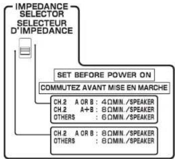
BepxHee nooxKeHne
BbEepriTe 3ty onlHIO, eCNI cIeTema KOLIOHOK COOTBTCTBYET OHNHY 13 cnLdyIOH yCNLOH.
- PII NOJIKIOHCHN KOJIHOK C COPTOMBOHNOH MEOO 8 Ω (HO 60IOE 4 Ω) K PA3BHYCH CH.2 A INM CH.2
P1IcNtObONABHn DYB nap KOHOHNO, OIOHBpeMENHO NOIOHNBOHEHHK Paa3bEMAM CH2 A/B, NcnoMbEyte KOnHOHKn B O IaKaHOBAN CH2 A nCH2 B
- PIP NOJIKIYOENH KONOHOK C cONOTINBNEHM MEHEE 8 2 (He 60nee 6 2) K B3BcEMAM KONOHOK, OTYNHbEM OT CH.2 A NHN CH.2 B
HnHexee noJIOJIeXeN (no yOmoTHAnIO)
Bb6e9E 37y ONIOI pnn IIOJIb30aHnK OIOHO K c COPTOBHHEHM 8 Ω IIbHIe.
PnokKnIOueHne Ka6eNe KOnoHOK
Ka6eHn KONOHOK COCTOHT N3 DByX npoBODHHKOB. ODHN NODKHIOAHTC9 K OTPiuaTeBHOmy (-) pa3bemy annapata N KOLOHKn, a pyroR - K noONoxKTENHOmy (+). ECIN npoBOa IMEOT pa3bHn CEBT, TTObI IN Hb3y 6blNo nepenyTaB, NOKNIOYte YepHbN npoBOk NO pOniTaTeBHOmy pa3bemy, a pyroR npoBO- K noONOXHTeBHOmy.
1CHMMNTe npBnHHTaBHO 10 MM H3OJIaM HA KOHcX Ka6Ea KOnOHKn HaDExHOCKpyTtE oroHHe bIyactn npOBIOB.
②OTkpyTnTe pa3bEm HA KOJIOHKe.
③BCTABTe ORoJIeHbIe IPOBaOa Ka6eN KOnOHKn B UeINb Ha 60KOBo CTOpOHe pa3BeMa (NeBov BePxHRe Nn npabO HxHKeH).
43aTHHTpepaBem.
NcnoB3OBaHHe BnIKu TTeKePHoro TMna
(Tonbko B moDEnax dNc CLU, KaHaNbl, KTuA TaBbHa (KTuTn) n ABCTpAnn)
①3aTAHNTpepaBemHaKOJIOHKe.
② BCTaBBTe BNIKy WTEKePHoro Tmna B Topepa3bema.
NcnoB3OBAHHeY-06pa3HOro HAKOHEHHKa
①OTKpyTnTe pa3bEm Ha KOJHOKe.
② BCTaBBTeY-06pa3HbI HakoHeHHK B KaHaBky MeJy pyHKOIN OCHOBaHEm pa3BeMa.
③3aTRAHIMTe pa5bEM
IopknoueHne cnoBoro ka6ena
NocTe TOrO KAc BCE NOckNochEnH NpeKcnOChEnH 6yUT BbINONHeBb, NOckIOUHTe NoCTabnHembl KaebIb NtAHnK Anapaty, a 3aTEM KpO3eTKe.
Annapat (BvDc3a)
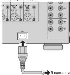
HAcTeHHyIO po3eTKy nepoMeHHoro TOKa.
BkIoueHne I BbIKIOUeHne annpapaTa
Haxmte (nntaHn),y06bBkIOuHTb nI bKIOuHTb annapat.
Ecn annapat BkIOueH, 3aropaetc HnIKKatop nTahn.

EeKn KTHEY TRIGGER IN NOKIOHO BHEUHBE YCTPOCTBNO HAXHTHO KHONK (I)NTANHE) annapat npexxOJNT B EKKM OKHDAHN. ECNI BKIOHTB BHEUHBE YCTPOCTBO,annapat 8OMATNNECKB KNOHETA C NOMIOZ FOYHKIM TTPRHPA (ctp.9).
PpOue FyHKcun
ABTomatueckoe BbIKIOueHne annapaTa (fynKunn ABTomatueckoro nepexOda B pexm OxuaHna)
Annapat aTOMaTHUeCKn nepeXoJNT B peKIM OxNJaHr Ype3 8 cAcOB nocne BKIOUeHn annapata.
TObblOKHIOHTbFHyKUHOABOTAMUHeCKOpeXoDABpexmOxuHaHn, nepeBeDInTepeKIOUaTeNbAUTOPOWERTANDBYBOOnOKeHne"OFF".


ΦYHKUNA 1ABOTMAHNECKORO nepeXODA B PEXM OOXIADAN PABOTAG, DAXE ECN BYNONHETCRB HOPDOKBDEHNE
PnI pAnKbHcHcHcN CIOCTMOHOR KOHTpONBHO KAOJIa KHOEDY TRIGGER IN yDHNKU bATOMATHCOKO RNEPOXDA E PEXMH OMADHAI HpoAOTAI DAKO cCN BKNIOHO.
Ocna6neHnCBeTaMHdkaTopaNTaHn
Moxho ocnaibtcbet HndkaTopa nitaHn, paonnoxehHoro Ha nueboi ctopohe annapata.

Ecnn K n3eTY TRIGGER IN NOKIOHO BHEHIE yCTPOIcTO, BIKIOHTE erO. npexde HbONIMtB cnnooyo npoeuydy.
① Ecnn annapat BknoH, HaxMnTe (NtTaHn) dnn erO tKnIOHeHn.
② HaxMMTe KhoNkO (nTaNHe) TpKDbB TeChHe 3 cekyHd.
CBETHINDKAToPA NMTAHNRCOJIABHET.

- 4TO6bI OTMeHHTb Ocna6neHHe CBeta,CHOBa BbINONHtE 3Ty npOeDpy.
EcnKa6eBnHTaHnOToCoeDnHe,ocna6neHnCeBt6yTeOTMeHeHO.
Bknouhene annapata BmeTe npu pa6ote npyunx yctpoinCTB (fynkna Tpuirepa)
Функштгетаоьнгупаьгьт bntaHem annapataHa npdC y npabHeHem
dpymmyyctpoCTbAMn, a TAKKc KOHTPONIPPOBbT bNTAHne dpyrnx yctpoiCTB BMECTe
c BKNIOYEHNEI bblNIOYEHNE MTOI ANAPATA. pRn cNOJIb3BaHN yCNITENI
MOUHOCTH NNN Cabybpapa YamaHa, noDpeXbaIOero fHyKNUO TprrrpTa, Moxho
NCNOL30aBTf FHyKNUO TprrrpTa, noKnIOHb yctpoiCTBa K rHe3dAm TRIGGER c
NOMOJIb PnpunaerMo RcTeMHoro KOHTPONlBOrKa6eII.
B 3aBcImocnOT npEiNoIarAemoro nCnoIb3oBaHnroNkIOuHTe yCTpoCTBO K ODHOMY I3 cneDyoux rHe3d TRIGGER.
The3do IN:
Плдкгнчсгсгсгсгсгсгсгсгсгсгсгсгсгсгсгсгсгсгсгсg(HANPIMPE, npdycinnteN)
ECNBIKIOHTb NII BIKIOHTb BA BCTyOCTBTO, ANIAPAT AOTOMATTNECKIN BIKIOAETCIN IIIB KIOAETCn (NEPEOXID T B EKIMM OXDAHNA).

-3Ta dyHKmua DoCTynHnToBko npn BkNoeHHo(HaKaT)KhONKe (nmtahme).
THe3oTHROUGHOUT:
3To rHe3Do BBIOBnIT CnHaJIbI, pPnHmAmEMbI Ha rHe3De IN.
Pn noKnIOUeHm yCTpOCTBa, noDepKnaBaoIero FyHKuIO TpRrEPHO BXoA (HANPMED, DpyTOYOCNNTENMOOHOTIN), BAAE YCTPOCTBO ABOTMAHTHECKN BKIOHOTCR INBbIKNOHTCR BMEcTe C BKNIOHcEHMe IM NbBkIOHcEHMeYCTPOCTa, NOKnIOHcEHORO K rHe3dy IN.
Tne3o OUT:
NnDnKJIOHueHNEyCTPOBCTBA,NOIeDPXKBIAOUCERO yHKNUO TPRITREPHO BXODA (HANPMep, cabbycpa).
EcnB KIOHTB NIM BIKIOHTB (nepeoxB CnAun pexm) annapat, yctpoCTBO aBTOMATHECKN BIKIOHTCnI, COOTETCTBEHO, BIKIOHTCn.

TOb6IpoNIOKIOHb HcOeBKO yctOPOCTB KTH3dAM TRIGGER. Hoo6xoJIMO mIoNIOBbAT DoCTyINbE BnpOdoae MOHOPOHIOHEKNE MNNa-KaEBNO
PacunpenHHa KOnHpyauqna KonoHok
PpeynpeKdHne
IpejBbIOJIHHeHmIOIbIXoCoUdJIeHHn IIN PAJOTOcNPEKNOUATEHMM3IaJIeKHTE 13 HACTeHN0PozTeKIOpeMeHHoTOKo TIOIcIKOBK ABiIAPATA.
IcnoIb3OBAHne KOLOHKn, noIepKnBaIOeI NOIKIOUeHHe cDByXKaHaBHBIM yCUNJeHNEm
EcnH Heo6xOIMO HcNoIb30BaTb KOHky, KOTopar NoIdepKnaBae CoeINHeHMe C dByHAnpAbeHHbIM ycNHeHEM DnA DoCTIXKeHNA BblCOKOKaHECTBEHHO 38yHaHnA, N3MeHnTe HacTPOkY CH. SELECTOR nIOKnIOHnTe KOHky K COOBETCByOouen nape pa3bEmOB SPEAKERS.
(Пумер)
NcnoJIb3OBAHnE KOIOHKn, NOIePKeINBaIOUeI NIOKIIIOUeHne C DByXKaHaJIbHbIM yCInHeHm dIa CH.2 (R)
NpeBEOI nepeKIOHOTaEN CH. SELECTOR IAH CH.3 (R) B noonoxHe "CH.2" npBIOIT K bIbOy BxObHb CXnHOB CH.2 (R) c 06oix paBemOB KOHOK CH.2 (R) n CH.3 (R). B TOM cyuee BXOCH.3 (R) He nOnbnEycTc.
PpeynpeKdHne
Ipeep BbHINHEHm CdeHHHnB DxykHAHbHOrG yCNHeHnA H3aKHeN KPOHHTbHnNnKABeH, coaeHHIOH NIKKBOACTOHTHnB uBDOHOe CMOTnE hNCTpyKIO nOKCNIPTALAIg NOKOHc. Ectne H NCKoYTOrD CdeHHHnC HcYkHAHbHnNnCYNHeHm, neep NDJKNQHOeHN KbaEnB KOHNHOyBgeTcb, YTOpeRbHKnNnNnKBeHNO
IcnoB3OBAHne IbYx nap fpoHTaIbHbIX KOHOK (SPEAKERS A/B)
PnnoKIOHmIbYxnapfoHTaIbHbIXKOHOKTEPMHaAMCH.2A/BMOXHO nepOKIOHtBCrMAOxyfPOHTaIbHbIMKOOHKAMn,HaxkBKNONKY SPEAKERS A/B Ha IJIeBOI NaHEIN annapata

- PIPINCOIOTOBAHMDBYAPKONOHOKOHDIOBPEMEHOPOKIOHOOHNIXKpA3eMMCH2AVB,NCN0b3yIe8-OMHbkeONKHOHNpepeBtepepeBnEPEDANCESELECTOR(CenekTop COPTOPENHEBMBEHPXNEOHXEEMC(CTP.7).
Ucnolb30BaHne Tpex KOJIOHOK nIa OJHO KAHaNA (HeCKoJIbKO KOJIOHOK)
ECNHNHO6XOdHMOIcN0NtB3oBAtbTnKONOHKnIyBOCNPOM3REDeHNAyDIOOCINHANOB CH.1 (HapmMep, CnHJIaIe cHTpAIIHOrKaHana), I3MeHNTe HACTPOky CH. SELECTOR nNoDKNIOHOT KOJNOHKn K COOTBETCTBQyOMMpa3EbnAMCH.1 nCH.4 (J/Π).
Ppnoxehne
Cxema npoxoKdHnBxOaunxCOaun cnrHanOB
Ponck nyctpaHne HeucnpaBHOte
Ecn annapat fyHKuOnHypeT HenpaBnIbHO, CM. npBedeHnyo Hxke Ta5nUy.
EcnBaasa np6bna He yka3aHa B TaBnue nnpBeHHe Hxke HnCTpyKuH He NOMOrn, BblKnIOHTe annapat, OTeCduHtce CInOBo Ka6eNb N 6paTntecb K 6nnKaHMeMy ABTOI3OBAHNOy Dnepny nB cepbcnh lyama.
HOMHHaHaBbXIOdHaMoOHcTb(2KaHana) (ot 20T4do 20KfU,0.06%THD,6s2)
CH.1 170Bt
CH.2 (L/R) 170 Bt
CH.3 (L/R) 170 Bt
CH.4 (L/R) 170 Bt
CH.5 (L/R) 170 Bt
CH.6 (L/R) 170 Bt
(ot 20Fdu 20Kfu,0.06%THD,8Ω)
CH.1 150BT
CH.2 (L/R) 150 BT
CH.3 (L/R) 150 BT
CH.4 (L/R) 150 BT
CH.5 (L/R) 150 Br
CH.6 (L/R) 150 Bt
(1KΓ4,0.9% THD,8Ω)
CH.1 170BT
CH.2 (L/R). 170 Bt
CH.3 (L/R) 170 Bt
CH.4 (L/R) 170 Bt
CH.5 (L/R) 170 Br
CH.6 (L/R) 170 Bt
- HomHaBHa BixOHa MoHocb (1 KaHaI)
(1K4.0.9%THD.6Ω)
CH.1 230 Bt/kaH
CH.2 (L/R) 230 Bt/kaH
CH.3 (L/R) 230 BT/KaH
CH.4 (L/R) 230 BT/kaH
CH.5 (L/R) 230 BT/KaH.
CH.6 (L/R) 230 BT/kaH.
(1 kF4, 0.9% THD, 8Ω)
CH.1 190 Bt/KaH.
CH.2 (L/R) 190 Bt/KaH
CH.3 (L/R) 190 Bt/KaH
CH.4 (L/R) 190 Bt/KaH
CH.5 (L/H) 190 BT/KaH
CH.6 (L/H) 190 BT/KaH.
(1 kF4, 0.9% THD, 4Ω)
CH.2(L/R)[MoJennnBEnKo6pTuHmN EbpOnb]
290BT/kaH
- Makcmmabhar 3666KTHBHA BbXoHAR MOuHOCTb
(1 kahan, JEITA)
[Moenn TaBaa (Knta), Kopen n cTpan Aan]
(1KΓu, 10% THD, 6Ω)
CH.1 280 Bt/kaH.
CH.2 (L/R) 280 Br/kaH.
CH.3 (L/R) 280 Bt/kaH.
CH.4 (L/R) 280 Bt/kaH.
CH.5 (L/R) 280 BT/KaH
CH.6 (L/R) 280 BT/kaH
(1KΓu,10%THD,8Ω)
CH.1 230 Bt/kaH.
CH.2 (L/R) 230 Bt/kaH.
CH.3 (L/R) 230 BT/kaH
CH.4 (L/R) 230 BT/KaH
CH.5 (L/R) 230 BT/kaH.
CH.6 (L/R) 230 BT/kaH
-ДиhammHeckaM MoHocTh (IHF)
1 kaH. (8/6/4/2 Ω) 190/250/350/500 Br
Ko3cphnneHTdMnppoBaHH
BceKaHaJIb1Kr4,8Ω. 180nBblwe
BxOHaHyBCTBNTeJIbHOCTb/BxOHaHOHMNEAHC
HecmmMeTpHuBb(1Kt,100BT/8Ω) 1.0B/47K
[Moeln DnB BnKobpTaHm Ebp]
230 a nepemehoro Toka, 50 T
[Mo]
220-240 B nepemehhoro toka, 50/60 T
TnTope6nMaMMAOHOCTb
[Moennn CwA n Kaanb] 650BT/850BA
[Moelb nKopen] 550BT
[Дуггел Мо徳и] 650Вt
IOTPe6JIHREMAOIOHOCTB B PEXKIME OXKIDAHNIA 0.1BT (TINMHNA)
MaKcHmAbHaN NoTpe6nEeMaM MoHocTh (Bce KaHab1 10%
THD)
[Moden Taa TaBn (Knta) n A3nn] 1500 Bt
-ITOpE6nHEmARMOUHOCTb(63cunHAnOB)....75BT(TNOBAr)
Pa3MedbI (Ux B x Γ) 435 x 210 x 463.5 MM
CyyHOTOMHOKOKBbCTyNOB
Bec 25.4 kr
TEXHHECKKXapakTePcTNMOYr H3MeHrtbca6e3
yBdOmneHn
使用预防措施
(1kHz,0.9%THD,8Ω)
CH.1 170W
CH.2(L/R) 170W
CH.3 (L/R) 170 W
CH.4 (L/R) 170 W
CH.5 (L/R) 170 W
CH.6 (L/R) 170 W
| 別名简称 | StViViViViViViViViViViViViViViViViViViViViViViViViViViViViViViViViViViViViViViViViViViViViViViViViViViViViViViViViViViViViViViViViViViViViViViViViViViViViViViViViViViViViViViViViViViViViViViViViViViViViWi |
8Ω 8
SsFkIeIiJ
SfoKJFJIeBfIeHbEeNtJFJFJIeBfJIeBfJIeBfJIeBfJIeBfJIeBfJIeBfJIeBfJIeBfJIeBfJIeBfJIeBfJIeBfJIeBfJIeBfJIeBfJIeBfJIeBfJIeBfJIeBfJIeBfJIeBfJIeBfJIeBfJIeBfJIeB