
CXA5000 - Home cinema amp YAMAHA - Free user manual and instructions
Find the device manual for free CXA5000 YAMAHA in PDF.
| Product Type | Home Theater Amplifier |
| Brand | YAMAHA |
| Model | CXA5000 |
| Channels | 11.2 (11 channels + 2 subwoofers) |
| Output Power | Approx. 150 W per channel (8 ohms, 1 kHz, 0.9% THD) |
| Power Supply | Mains (cable included) |
| Power Consumption | Approx. 800 W (max) |
| Dimensions (W x H x D) | 435 x 192 x 468 mm |
| Weight | Approx. 17 kg |
| HDMI Inputs | 8 inputs, 2 outputs (including ARC) |
| Pre-out Outputs | 11 RCA channels + 11 XLR channels |
| Subwoofer Outputs | 2 (RCA) |
| Analog Audio Inputs | RCA, optical, coaxial |
| Supported Audio Formats | Dolby TrueHD, DTS-HD Master Audio, multi-channel PCM |
| Key Features | YPAO (acoustic calibration), CINEMA DSP, 11.2 channels, preamplifier |
| Radio Tuner | FM/AM with included antennas |
| Included Accessories | Remote control, AAA batteries (x4), YPAO microphone, AM/FM antennas, power cable, CD-ROM (user manual) |
| Maintenance and Cleaning | Dust with a soft, dry cloth. Do not use solvents. |
| Safety | Disconnect before any connection. Do not expose to moisture. Use the provided power cable. |
| Spare Parts and Repairability | Contact an authorized Yamaha service center. Parts available depending on model. |
Frequently Asked Questions - CXA5000 YAMAHA
User questions about CXA5000 YAMAHA
0 question about this device. Answer the ones you know or ask your own.
Ask a new question about this device
Download the instructions for your Home cinema amp in PDF format for free! Find your manual CXA5000 - YAMAHA and take your electronic device back in hand. On this page are published all the documents necessary for the use of your device. CXA5000 by YAMAHA.
USER MANUAL CXA5000 YAMAHA
This document explains how to set up a 11.2-channel system and play back surround sound from a BD/DVD on the unit.

To reduce the impact on natural resources, the Owner's Manual for this product is supplied on CD-ROM. For more information about this product, refer to the Owner's Manual on the supplied CD-ROM.

PDF versions of this guide and "Owner's Manual" can be downloaded from the following website.
http://download.yamaha.com/
1 Preparation
Accessories
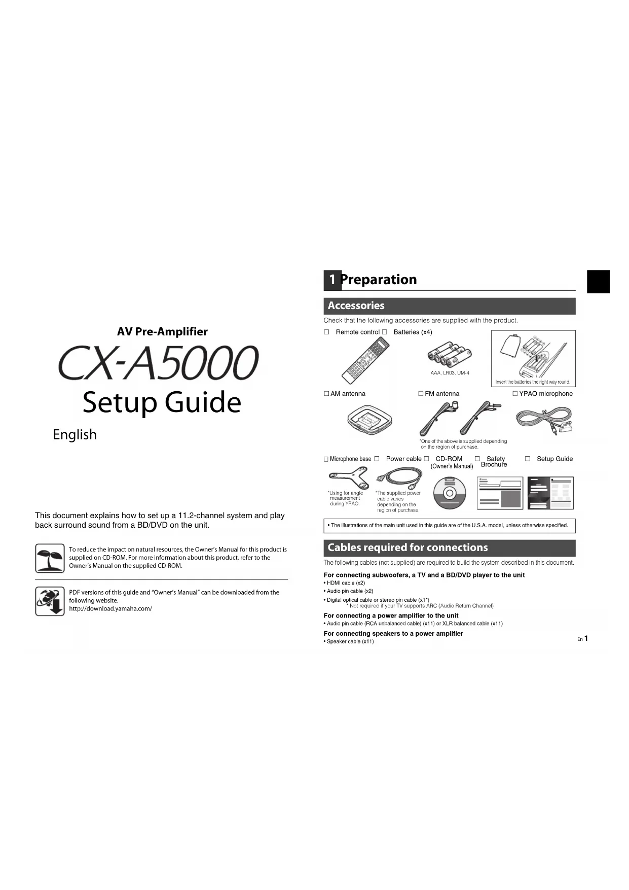
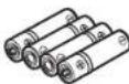
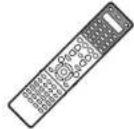
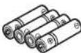
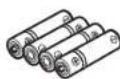
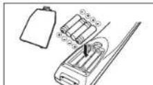
Check that the following accessories are supplied with the product. Remote control Batteries (x4)
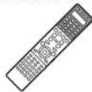
AAA.LRC3UM-4
Insert the batteries the right way round.
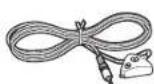
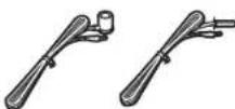
□AM antenna
FM antenna

One of the above is supplied depending on the region of purchase.
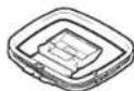
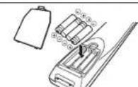
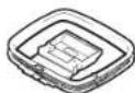
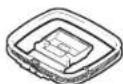
□YPAO microphone
Microphone base
Using for ang measurement during YAPC.
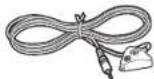
Power cable
The supplied power cable varies depending on the region of purchase.
CD-ROM

Owner's Manual) Brochure
The illustrations of the main unit used in this guide are of the U.S.A. model, unless otherwise specified.
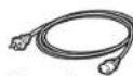
Cables required for connections
The following cables (not supplied) are required to build the system described in this document
For connecting subwoofoers, a TV and a BD/DVD player to the unit
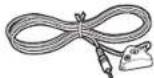
HDMI cable (x2)
Audio pin cable (x2)
- Digital optical cable or stereo pin cable (x1*) Not required if your TV supports ARC (Audio Return Channel)
For connecting a power amplifier to the unit
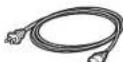
- Audio pin cable (RCA unbalanced cable) (x11) or XLR balanced cable (x11)
For connecting speakers to a power amplifier
- Speaker cable (x11)

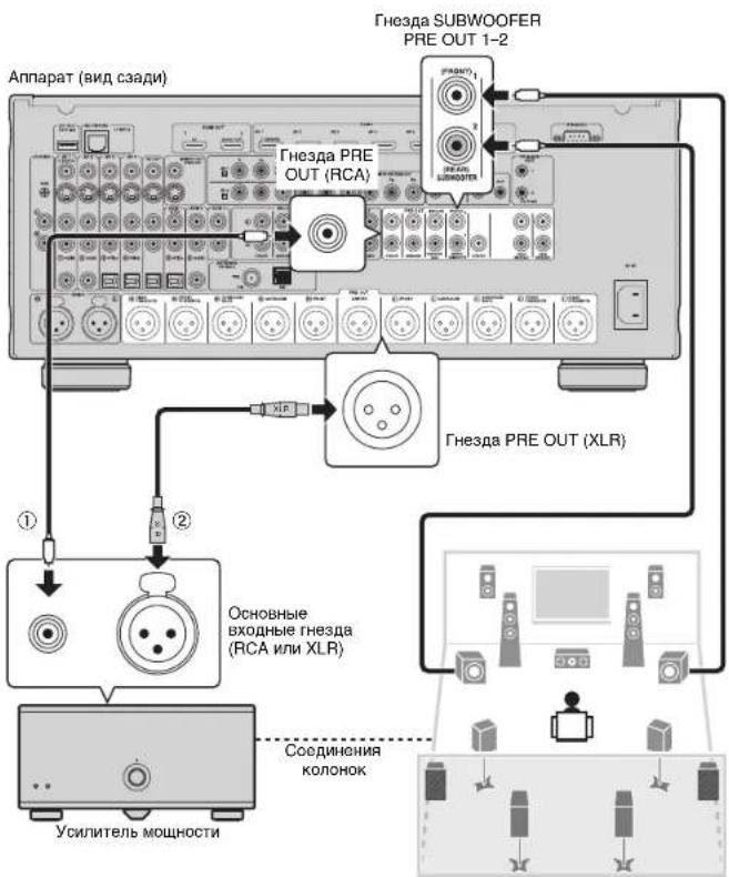
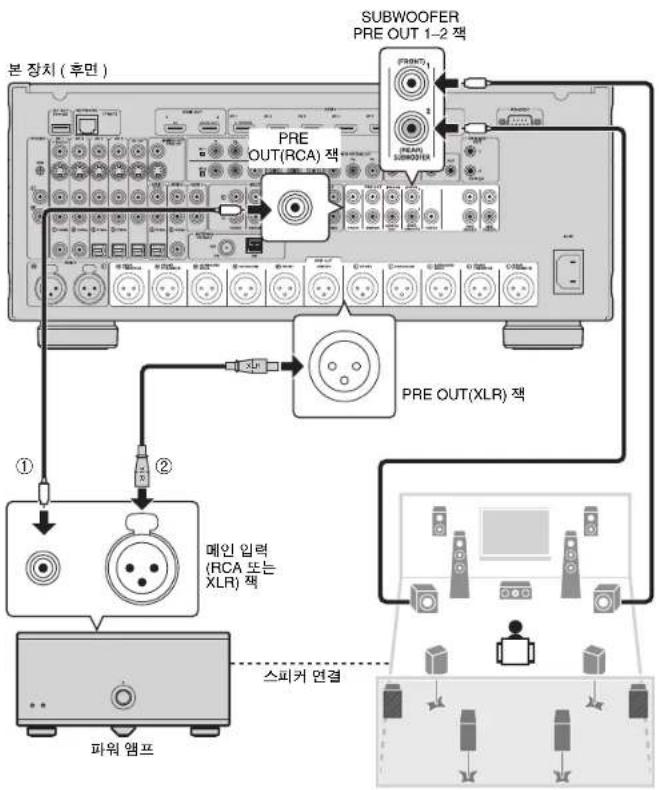
2 Connecting a power amplifier, speakers and subwoofer
Connect a power amplifier and subwoofer (with built-in amplifier) to the unit, and speakers to the power amplifier.

- Use a subwoofer equipped with built-in amplifier.
- Before connecting a power amplifier and subwooters to the unit, remove the power cables of the unit, power amplifier and subwooters from the AC wall outlets.
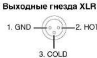
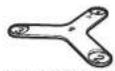
The pin assignments for the XLR output jacks of the unit are shown below. Before connecting an XLR balanced cable, refer to the instruction manual of your device and verify that its XLR jacks are compatible with the pin assignments.
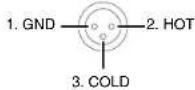
XLR output Jacks
1 Connect the PRE OUT jack of the unit to the main input jack of the power amplifier for each of 11 channels (① or ②).
When making unbalanced connections (①), connect PRE OUT (RCA) jacks of the unit to the main input (RCA) jacks of the amplifier with audio pin cables (RCA unbalanced cables).
When making balanced connections (②), connect PRE OUT (XLR) jacks of the unit to the main input (XLR) jacks of the amplifier with XLR balanced cables.
2 Connect the subwooers (with built-in amplifier) to the SUBWOOFER PRE OUT 1-2 jacks of the unit with audio pin cables.
3 Connect each speaker to the corresponding speaker terminal of the power amplifier.
For details on speaker connections, refer to the instruction manuals for your power amplifier and speakers.

- Depending on your power amplifier, you may be required to change its settings so that audio received from the unit is come from the speakers connected to the amplifier.
- You can connect 2 subwoofer to the unit and place them on the right/left (or front/rear) sides of the room. When using 2 subwoofer, configure the "SWFR Layout" setting after connecting the power cable to an AC wall outlet. For details, refer to "Owner's Manual".
- If you have a Yamaha power amplifier that supports the trigger function (such as MX-A5000), you can control the power amplifier in conjunction with operating the unit (such as powering on/off) by making a system connection. For details, refer to "Owner's Manual".
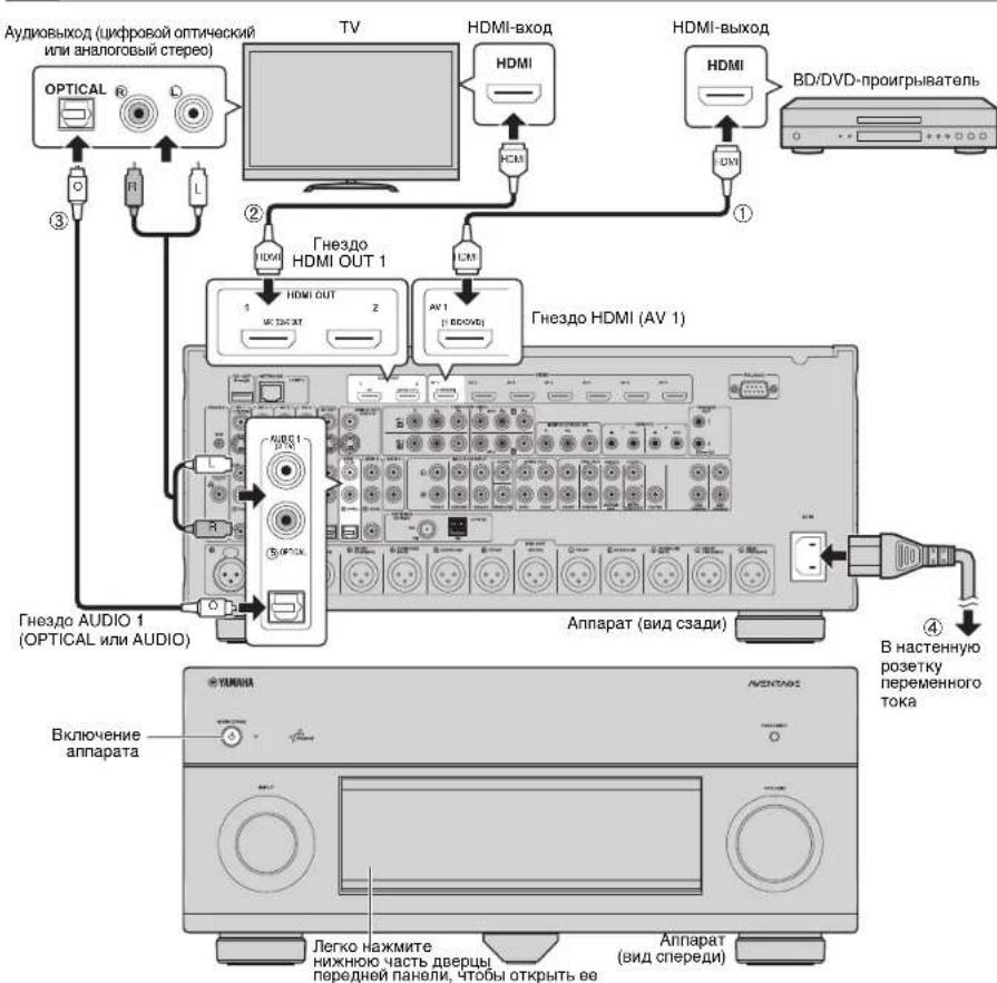
3 Connecting external devices
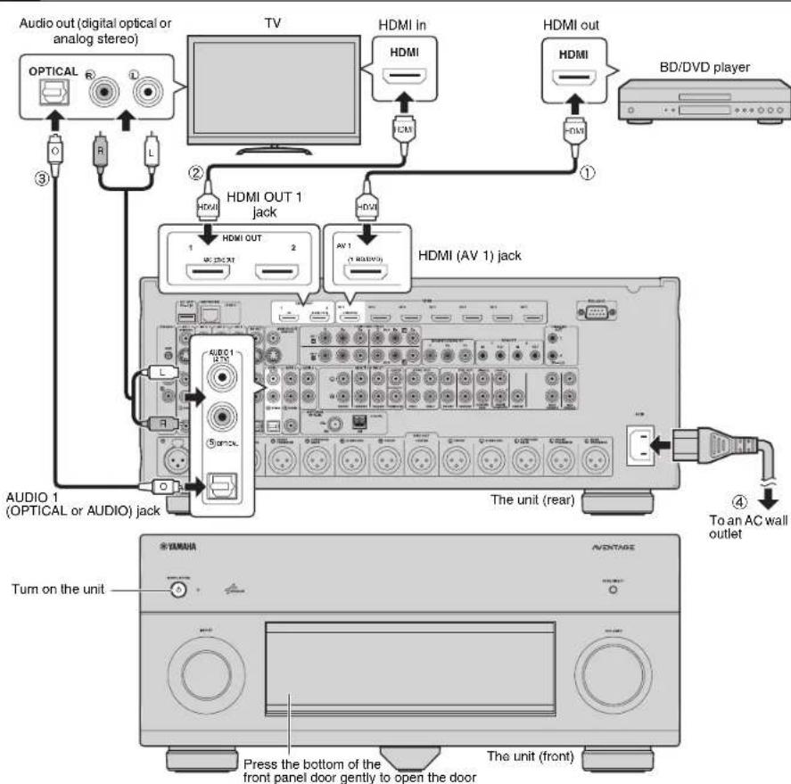
1 Connect external devices to the unit.
① Connect a BD/DVD player to the unit with an HDMI cable. If the BD/DVD player is currently connected to the TV directly with an HDMI cable, disconnect the cable from the TV and connect it to the unit.
② Connect a TV to the unit with the other HDMI cable.
3 Connect a TV to the unit with a digital optical cable or a stereo pin cable. This connection is required to play back TV audio on the unit. This connection is not required if your TV supports ARC (Audio Return Channel).
Connect the supplied power cable to the unit and then to an AC wall outlet.

- For information on how to connect radio antennas or other external devices, see "PREPARATIONS" in "Owner's Manual".
2 Turn on the unit, power amplifier, TV and BD/DVD player.
3 Use the TV remote control to change the TV Input to video from the unit.
The connections are complete. Proceed to the next page to optimize the speaker settings.

- You can select the on-screen menu language from English (default), Japanese, French, German, Spanish, Russian, Italian and Chinese. For details, refer to "Owner's Manual". In this guide, illustrations of English menu screens are used as examples.

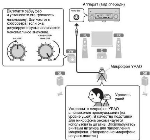
4 Optimizing the speaker settings automatically (YPAO)
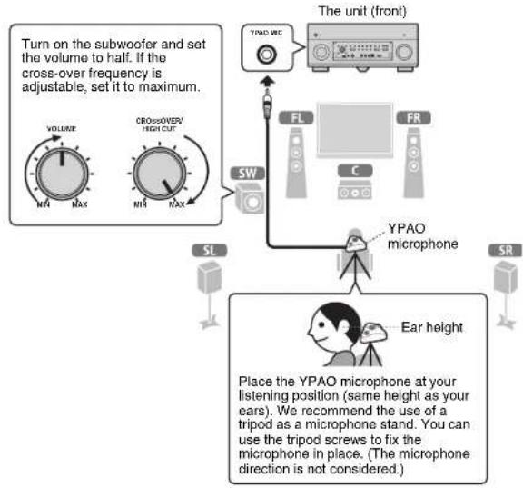
The Yamaha Parametric room Acoustic Optimizer (YPAO) function detects speaker connections, measures the distances from them to your listening position(s), and then automatically optimizes the speaker settings, such as volume balance and acoustic parameters, to suit your room.
- During the measuring process, test tones are output at high volume. Ensure that the test tones do not frighten small children. Also, refrain from using this function at night when it may be a nuisance to others.
During the measuring process, you cannot adjust the volume.
During the measuring process, keep the room as quiet as possible.
Do not connect headphones.
- Do not stand between the speakers and the YPAO microphone during the measurement process (about 3 minutes).
- Move to the corner of the room or leave the room.
Preparing for YPAO
1 Connect the YPAO microphone to the YPAO MIC jack on the front panel.
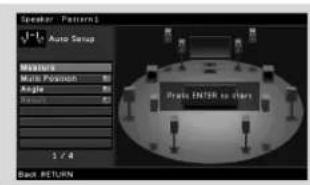
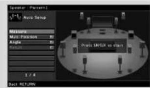
The following screen appears on the TV.

- To cancel the operation, disconnect the YPAO microphone before starting the measurement.
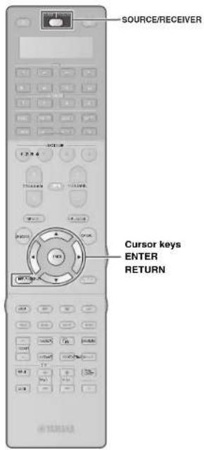
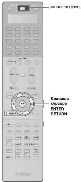
2 To start the measurement, use the cursor keys to select "Measure" and press ENTER.
The measurement will start in 10 seconds.
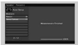
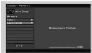
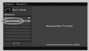
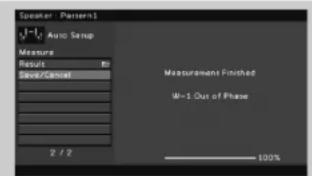
The following screen appears on the TV when the measurement finishes.

- If the cursor keys do not work, press SOURCE/RECEIVER (to light up the key in orange) and then use the cursor keys.
- If any error message (such as E-1) or warning message (such as W-2) appears, see "Error messages" or "Warning messages" in "Owner's Manual".
- If the warning message "W-1:Out of Phase" appears, see "If "W-1:Out of Phase" appears" (next page).
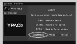
3 Use the cursor keys to select "Save/Cancel" and press ENTER.
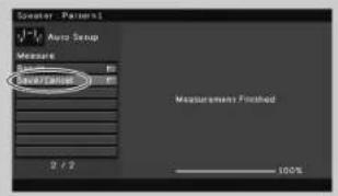
4 Use the cursor keys to select "SAVE" and press ENTER.
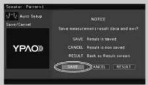
5 Disconnect the YPAO microphone from the unit.
This completes optimization of the speaker settings.
- The YPAO microphone is sensitive to heat, so should not be placed anywhere where it could be exposed to direct sunlight or high temperatures (such as on top of AV equipment).
If "W-1:Out of Phase" appears
Follow the procedure below to check the speaker connections.
When you have made balanced connections
- The XLR balanced jacks of your power amplifier may not be compatible with the pin assignments of the unit. In this case, turn off the power amplifier, change its pin assignment setting or use unbalanced connections, and then try YPAO measurement again.
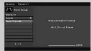
① Use the cursor keys to select "Result" and press ENTER.
Use the cursor keys to select "Wiring".
③ Check the cable connections (+/-) of the speaker that was identified as being "Reverse" in the warning message.
If the speaker is connected correctly:
Depending on the type of speakers or room environment, this message may appear even if the speakers are connected correctly. In this case, you can ignore the message. Press RETURN and proceed to step 3.
If the speaker is connected Incorrectly:
Turn off the unit, reconnect the speaker cable, and then try YPAO measurement again.

5 Playing back a BD/DVD
Now let's play back a BD/DVD.
We recommend playing back multichannel audio
(5.1-channel or more) to feel surround sound produced
by the unit.
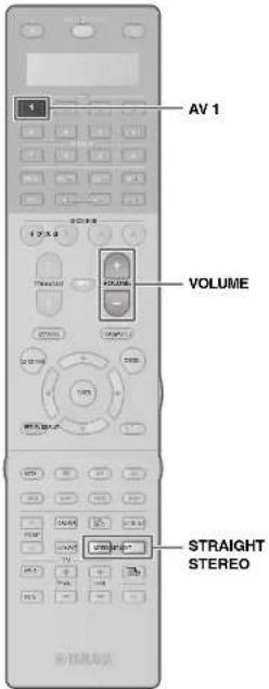
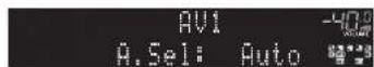
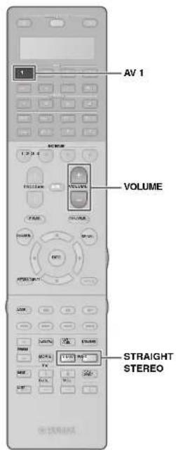
1 Press AV 1 to select "AV 1" as the input source.
2 Start playback on the BD/DVD player.
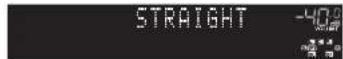
3 Press STRAIGHT repeatedly to select "STRAIGHT".

- To check if sounds are properly heard from all speakers, press STEREO repeatedly to select "11ch Stereo".
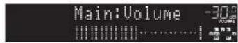
4 Press VOLUME to adjust the volume.
This completes the basic setup procedure.
If surround sound is not working
Sound is only being output from the front speakers during multichannel audio playback
Check the digital audio output setting on the BD/DVD player.
It may be set to 2-channel output (such as PCM).
No sound is coming from a specific speaker
See "Troubleshooting" in "Owner's Manual".
Many more features!
The unit has various other functions.
Please refer to "Owner's Manual" on the supplied CD-ROM to help you get the most out of the unit.
Connecting other playback devices
Connect audio devices (such as CD player), game consoles, camcorders, and many others.
Selecting the sound mode
Select the desired sound program (CINEMA DSP) or surround decoder suitable for movies, music, games, sports programs, and other uses.
Playing back from iPod
By using a USB cable supplied with iPod, you can enjoy iPod music on the unit.
■ Listening to FM/AM radio
Playing back music stored on a USB storage device
Playing back the network contents
Selecting the input source and favorite settings at once
For more information, see "What you can do with the unit".
c dncka BD/DVD Ha annapate.

CueIbIO 3KOHOMHOHNCIOJIb3OBAHnnpnoDhbIXpeCyPCOBHCTpyKUINIO
3KcNlyaataun DaHHOR npOyKTa NOCTaBnETCR HA KOMNaKT-DnCKE.
IIOONHNTBHLBE CSEHNEI DA HONIO PMOYKTE CM. B INCTPCKUNI PO 3KNPIAYATAU NH PAINRAEOM COMAKKT-DNCKE.

PDF-BePcMn DaHHoro pyKOBoDCTBa n "Hhctpykun no 3Kcnnyataun
MOXHO 3aRpy3ntb co cneDyiooero Be6-caTAt:
http://download.yamaha.com.
1 NpOtroTOBka
PnHaJdxXHocTn
Y6eNTecb, YTO B KOMNNEKT NOCTaBKN IN3dENNA BXODT CneDyUOUIne npHnAaNEXKHOCTN.
NynbDy BatapeKn (4Wt.)
AAA, LPO3.UM-4
BCTaBeTeBaTePeknHaDnEeXaZMMOc03a03m.
□AM-aHTeHHa
FM-aHTeHHa
B3BbVWVCTOHTOTDPVAHPOKNYKOTDQNTTETNQySyvSvYkSHyRy
MnKpocphYPAO
- 指诺达基,Дяй Миркобiosa

MnomnEyyertanTJH KmepnB yIyBb BxO2yYPAO.
CunonnoiKaeb
"TocdaaeebKaabeNTBnAe 3aamrOETPcnnHOKyK
KOMnAKT-DACK

(HNCTPYKUPIA N KCNPLTAYCUN)
□Bpcwnopa no
6e30nachocctn
PnykoB0DCTBO no
HACrpoKe
HaHIOIOCTaIaIIIN OCHOHOI IaPATA Npyta D Y B aDHHOM pykoBOCTBc H3O6pAXeHb MOJeb bHIOHNHeHnIaIaIaIaIaIaIaIaIaIaIaIaIaIaIaIaIaIaIaIaIaIaIaIaIaIaIaIaIaIaIaIaIaIaIaIaIaIaIaIaIaIaIaIaIaIaIaIaIaIaIaa
Ka6eH, Heo6xOaMbIe Ira nOdknUoyEnr
IpeueuCneHbIe daaee Kaebnn (He BXoJrB KOMnKeT NocTaBKn) Heo6xoDnMbbl,
YTO6bCKOHCTpyINPOBAtbCNCTemy,ONNCAHHYIO B DaHHOM DOKymeHTe.
Ди noKIOHcHnBaC6ByepeOB,TeJIeB3OpaI npOnrPbIbaTeR B/DVD K annapaty
KabensHDMI(2wT.)
-Tepehnyaynokaebn(2wT.)
Lcnpboo onTneckn kaebn nn Taepehnh cTepeokaben (1 wT.)
* He Tpe6yETCA, ecnn TeneBn3Op noDnePExnBaET ARC (o6paTHbI ayDnOKaHaN).
NnnoNkNoeHnYcHnntenMoHocnKannapaty
- UTeKepehny ayDnokKaebn (heCmmMeTpNnHb Kaebn RCA) (x11) nn CmmMeTpNnHb Kaebn XLR (11 wT.)
IINIOKNOHcHnK YcHnNTeHMOHOCTN
KaBEn nn noKnIOueHn KOHOK (11 wT.)
2Поdkлочиуспntя moцhoe, koloHOK n ca6ByepeOB
POnKnIOHTe yCunNTenb MoHOCTH n cabBypepb (co BCTpoEHBM ycunNTenem K annapaTy, a KOONHK K yCunNTeIO MOUHOCTN.
-
McnoIb3ayTe caBbydpep,obopyoBaHHb BCTpoeHHbIM ycHmTeneM.
-
Piepod noKNIQUHcMgY cYNTHoN MOUHOCTH N CabybOpeB K anapnpaty,OTCNOHN HKTaON mNTaHAn apnata, yCNHTnoN MOUHOCTH N CabybOpeB OTACTHEPOH p03eTOK PEmEHHOH TORA.
HIXe npBaeHa cXeMa KOHTAKoB aBbOxDnBnTHcAaXL.PaepnDnKIOHcHem CmmMertPnHc0 Ka6Ea XLNaHakomTBeC pkyoOaCTbOM no yctpOCTBy nYbEa XL RcoTETCTyOT cXeMa KOHTAKoB.
1 CoeHnHrTe rHe3do PRE OUT Ha annapate c OCHOBbIM BXoDHbIM rHe3dOM Ha ycUNITE moHOCTH nIra KaKdOrO u3 11 KaHAnOB (1)
PcOo3dHnHHeCmMmTPhHbX CoeDnHEHn (1) CoeDnHTHe THe3da PRE OUT (RCA)Ha annpaTe cOCHOBHb BXoDnHm THe3dAMn (RCA) Ha yCnHnTEne,
NCOnb3y WtKepeHbte ayDnKaeHb (HeCMmETPhHbte Ka6Be nRA).
PpOcO3dHnCmMmTPhHbX CoeDnHEHn (2) CoeDnHTHe THe3da PRE OUT (XLR)
Ha annpaTe cOCHOBHbIMBXoDnHm THe3dAMn (XLR) Ha ycInTeNe, NcOnb3y
CmMmTPhHbte Ka6Be nXLr.
2 NpOc0eHNHtE ca6ByepeBb (co BCTpoEHbIM yChnHTeMe) K rHe3dAM SUBWOOFER PRE OUT 1-2 Ha annapate, nCOnb3yra wTekepbhe aydnok6aen.
3 NocoeHNHTe KaKdyo KOJohky K COOTBETCTByIOseMy pa3bEmy KOJohKn HA yCNINTe MOUHcTn.
CBeDNEHNOI OPOKHOENHIX KOLOHOK CM. BYPOKOCTBAX NO YCNINTEIO MOIOCHNTN KOLOHOKAM.

B 3aBNCIMCOTNtNcNLSyEMORO yCNNTENRA MOnHCTN MOUHCTN MOKET NNOAODNBTCB HMSMEHHTB ERO HACPTOKHK, YTOB6 ayDIOCNHnABNb, NOCTyNAIOUIe C annapata, nepeBaabAAHC HA KONOHKK, NOKNKHNHEE K cYNCNTENHO.
K Anpatay MIOHOIO KIOHIOHTB DAB cA BDObpa H aONIOHOHTB N IO NO PABO H N Oe (PnOEOH 3aIaH) CTOPOMAMKOHTAH.PrnpNcHb5OBaHHaN DAXyBaDPOB nOeNC BkIOHOH CNIOBOBA KaBbN b POETKY NKepmEHOH TOKA HAcTPORe NaPaeTp PAcOn. CABVbD, PoipOBeHs CbeDEHN CMOTPIE V "HtCTpyKuNo HA KcnYNAATAH."
ПИМОДСЕВАМСЕВЕСТЕМОДСЕВЕСТЕМOLMADENTY.KOTOPБ NOДDEРSEXBAEТДУКПСТМТРЕТС(HAPIMPEM,MX-A5000),MOKHOYPNAPRATS-YCHINEMETMOMNOCHTEMHCTC BANTAPATOM(HAPIMPEM,BKNOKHTA BIKHOKTAYB MEXBECTE)COEJIIMINX HEPES CMESTHEMGE NOJDKHONHE.MIPODROSHYE CEBDEAHCMOTPTEB“WICHTPKUYANNO KECNIYATAA"
3 TódkloueHne BHeuHx yCTpoiCTB
1 PoiKlIOUHTe BHeuHHe yCTpoiCTBa K annapaty.
1 NoKIOHcyte BD/DVD-npOIRpbAteBn K annapary C nOMObko KaEBNA HDMI. Ecm BD/DVPnOIRpbAteBn noKIOHOHN HApmyio K TeneBIPOC npOMooaKaEBNA HDMI, OTOeMHNIte KaEBN ot TeneBmora npKIOHcHTEero K annapary
們 IOnKIOHOTeTeneBnO3OP K anapaty c NOMoBHO pyrroTOKaEbnHDMI.
10NoKIOHHTe TENEBnOOP K annapaTy c nMOUbIO
3UcPpOBOrO OITNIueCKoROp KaBeJI INI NtTEKePHOR
CTepeOKaBeJI.
3TO NoKIOHCHHE HHe6XoDMIO IINR BOCPOPA3BDEHMRA
ayDNOmHnAra TENEBnOHa pAn annpate, 3TO
NoKIOHCHHO He HHyHX, BCNA Bau TEWbHsOe
noJepkBaET dyHKnIO ARC (Audio Return Channel).
POKNIOHTe NocTABJIeMaK Ka6BeMaIITAHNA K Anaparaty, a 3aTeM K pO3eTKe.

CSeBENHOr O TOM, KAK NoKIOKIOvATaPdIoHOHTEHnIbIyIgTHyE BHHHHeY YcOPTOBcAe, Cm. 1paDeJeT "TOIOOTOBKA"
2 BkIIOUHTe annapat,TeJIeBn3Op n BD/DVD-nponrpblBaTeNb.
3 NcnoNb3yIte npblT DY TeneBn30pa dna H3MeHEnH NCTOCHNka BXoHORO BnEOChHAnA TBeBn30pa TAKHM 6pb3OM, YTO6bI OH NOKa3bBaIa BNEOChHAn C annapata.
Bb noDknHnH Bc0 Heo6xOammy Annapatpy.
Pepennte Ha cneyiouy cTpaHmU,Ha KOtopoi
OnbcBaetcKAK ONTMMN3IPOBaT HAcPOYKOJLOHK

BbMokote BbBabatHyhKsIb3kXpHARHO MHeHO HcNeDyHIOXu: AHnHKnKc (HCNBoYbTOcN OMyHANHO) ANOCKH, PdAUY3ckH NHEUKO, HAIHNKc, PyCCK, IVaTHNtHKcNMI KHTAOKHO. PNOoBOe CbeHEno CMOTPeV "VHcyTKuN no KcONnyatauLI BDAHmKpyOBQCTBe KCAHEePnIMpeoB KcONy3yTOcr KIObApEHHK ENOHO HArHINKcMOKSe
4 ABTomatnuecka ONTmM3aunna Hactpoek KOJohok (YPAO)
Функу明白Parametric room Acoustic Optimizer (YAPO) onpeDneHn noKnHueHHa KONOHK H3MepHET paccTOnRHE MekyHMy NNOXKeHHem CnyATeHn, a 3aTeM abOTMAHTeCKN ONTHMMNpyE HACTPOHK KOHOHK, TAKH KAK SbAHC rPOMKOCTH AkyCTCHeCKH No napAMetPSB, B COOTBETCN C XApakTepCNTKAMBAuBero NOUMOeHHJ.
B0EPMHMEPEHNAETOBBBCHNANBIBBODORC BbKOOKPROMKCKTOB. 乙dTeTcB,TOCTOBbCHNANBHOICYTAOMANTMHXQDETAE.TaIKeK63eTaIe IIOIOBAOTAHNOFTHQHUYHO,KORAHOMOKETNOOMAIEPOyIMNIOADM
TecTobBc CnHbI Bo BpMa NImpeHr BbBOaTcC BbICOKr pOMKocTBIO.
- Bo Bpemr nAmepenHn coxpaHnTE B KOMHaTe MaKcMaIbHyIO TmUHHy.
-He nooknouaTe Kannapaty HayuHnK.
He ctoTe MeKdy KOIOHKAMM NIKPOPOHCM YPAO BO BpEMH NMepeHHA (OKKO 3 MHHY)
- PepaDte By ron nmeuHn Hn Bn Dte Hc Hr
NoTobKa KnOJb3OBaHNO yHKuYPAO
1 NpoknHte Mkpofoh YPAO K rhe3ny YPAO MIC Ha nepehdne Hanei. Ha 3kpan TeneBn0pa 6ydt BbVeDeno CneDuOe He3o6PakHeHc

2 TTo6bHaaytBn3MepeHne, c nOmoBIO KnaBnKypcopa Bb6epTe "Measure" n HauKMTE ENTER.
N3MepeHHe NaHETcAepe3 10 cekyHd.
No OKOHuaHm H3MepeHn Ha 3KpaHe
TeneBn30pa NOBNTCR CNeDyIOUaI INHdNkaIaI.

- Ectn KnaBnHm Kypcope H naBoaTcA, HAKMITE SOURCE/RECEIVER (Tb6bK nKnBnHa BnHa NpOeBHeVn opAnxBeMbI UBeTOM), NoCne Yero KnoHo ByetD RocB003PcRz-CB KNaBnHmKynoC
EoNn IINBNTCA CoOooJIeH6 OooIke (HAnPmep, E-1) nnpIepnpeKEnHe (HanPmep, W-2), cm. paadJeN "CoOooJIeH6 OooIkeKx" nn "PepDynpKeJenHr" B "VHTcPKMnO NKcIpyaTALn." - EcmnoBnTcnpdeyprkDneHmepW-tOut of Phase" cm.pa3enEcmnoBnTcpo0eHmepW-tOut of Phase"(cnpooyua ctpnua)
3 C NOMOusbKnabHw Kypcopa Bbl6epnte "Save/Cancel" HnaKMnte ENTER.
C NOMOJIbI KJIaBNI Kypcopa Bbl6epnTe "SAVE" n Haxmnte ENTER.
5 OTKJIIOUHTe MHKpOΦOH YPAO ot annapata.
Ha 3TOM ONTHMM3aUNHACTPOEK KOJIOHOK 3aBepueha.
MmKPOPHYPOAOHYBHTENK TENTN,NTMOHY CHeHcyET NOMUHTB ERO S MCTB, IRe OH MOKET NOBEPATBOB 803DcE7BNOI PRMUMC OINMHHXI YJHMM BUBOKOH TEMPEATyBu (HAPMHPe, He CHeyET KNACTb MMKPOFOH HAUYHOHNBOOOPDYBOAHNE).
Ecnn noaBntc coo6eHne "W-1:Out of Phase"
IcnoB3yIe CneDyOuO npOeDpy nI npOBepKn NOKIOHIN KONOHOK.
Ppco3dAHn HecMMMeTpHuBix CoeHHHeHm
CMMMTPNHHE TNEA XLH YA cYNHTENe MOUHCTN MOTY K083aTc HECOBMECTMbI C KOHAKTAMM HAANAPATE. B 30TM OUYAE OTKNOHTe YCOHNTEb MOUHCTN, K3MMEHITTE HAZAHANEH KEHKTOBV IN NCHONB3yTe He CEMMHTPKTHIE COEINHINE, 3ATEM NOPTOP BHOINHITE MMEPHENTE YPAO.
1C NOMOIOJIIO KIANBIU KYPORCA BbIbepTe "Resuit" INaHXMITE ENTER.
② NomoubkoKnaBnKypcopaBbEpnte"Wiring".
③POBeBte NOKIOUeHHe KABeN(+)-KOLOH,OTMeHHHO BnpDynpExHm CNobOM"Reverse”。
EcnKoONHknoDKJIIOHeHa npaBnIbHO:
B3aucimocnOT TINNA KOHOK HNN NOMeueHHN 3TO coo6eHHNe MOKET OToPbKaTaBCaJBe Kcnyae npabInbHoro NOKmOeHHKOHOH
B daHOM clyuae Bbl moxete npnHropoBaTb coo6eHne.
HakmTe RETURN n nepeiTe K wary 3.
EcnKoJIOHKa noDKIIOyeHa HnpeBaINbHO:
BbIKIOHHTe annapat, CHOba noIOKIOHHTe ka6enb KOnOHKNa a 3aTeM NOBTOHTE npOceCC n3MepeHHYPAO.
5 Bocnpom3BeDeHne BD/DVD-ДиСka
Tenepb nonpobemy Bocnpo3Bectn BD/DVD-nick. PekomEnyEM BOCP04BECTM HMOK0HaJIbHbI 3ByK (5.1-KaJIbHbI INI 6OJIe) -3TO N03BOJNT NoYbCTBoaTb OKpyKaIOe 3ByAnHe, KOtOpoe co3daert annapat.

2 HaCHNHTe BOCnpon3BeDeHHe Ha BD/DVD-npOurpbIbATEne.
3 Heckonbko pa3 Haxmte KhoKy STRAIGHT dnn Bb6opa "STRAIGHT".


ДАнрберкпгавиьнсотьСВСРОПБЕНИЗУ 38уКВ BCIMKOKHMAHCKONIko раHAKMNTE KHOKNY STEREO.чтбвьбвТ"11chSTERO".
4 Haxmte KhoNky VOLUME anp perynpoBn rpmKocn.

Ha 3TOM npoueypa 6a3oB0n HacTpoKn 3aBepSeHa.
Ecn He pa6otaet okpykaiooee 3byaHne
3Byk BbBODHTCR fpoHTaIbHbIMN KOLOHKAMN TOJbKO BO pEMBO BOCPOH3BeDEHHM MHOROKAKAHSHORO 3ByKa.
PpOBeBte HacTpoKn BbIOBa unIpPoBOro ayIOcINrHana BD/DVD-npOINrpBbATEJr. Bo3MOxHO, Bb6paH BbIOB 2-KaHaJIbHOM pekmE (hanPmep,PCM).
He Bocnpon3Bodntc3ByK Chepe3 onpepeHnyo KOONky.
CM.pasden"PonckN yctpaHenne HncnpabHocTeB "NHCTpyKUIN no 3Knnyatauun".
ФункшиоуehbMHoro!
Annapat BKNIOaET TaKxE MHOXECTBO DpyNX pHyHKn.
DnI INONJb3OBAHnB CEX Bo3MOXHOCTe
anapata CM. "HHTcyPKn no 3KnnyATAu"
Ha npINRAEAMOM KOMNAKT-DACKE.
IopKnIOueHne pyrux BocnpOn3BOaunx yCTPOINCTB
PnKIOHauaTe aynOyctpoIcTBA (HanPMeP, CD-npOHRpbIaTeB), IPOBOBIE KOHCOIN, BDOKEAMpeN T. D.
Bb6oppeKIma3ByaHn
BbIepHTe HxHyXO 3ByKOBYIO IporpAMMy (CINEMA DSP) INN DEKOEP OKpyKaAIOero 3ByaHn, NOxOJIaONI Dn KHOQIpMbO8, MBykIn, INP, CNOPTMBHbIX IPOrPAMM IN dP.
Bocnpoun3BepeHne 3Byka c yctpoictba iPod
C nOMOBIO KABEJI USBX, BDOJAIIEBO KOMTIIEKT NOCTABIK iPOD, MOKHO BOCPNOB3BOIDITb My3Iky C yctOPOB3BA iPOD chepea annapat.
Послушване FM/AM-pадио
Bocnpoun3BeJeHne My3biknHa 3anomnHaioeymyctpoiCTbe USB
Bocnpn3BeHne My3bIKN u3 ceTN
BbICTpbB Bb6Op NCTOCHNBAxOHoro CnHaHn npednoHTaembix HAcTpoek
DOnOHHTenbHbIe CBeEHnHcM.Bpa3dJe "Bo3MOxHOCTn annapata."
AV前置放大器
CX-A5000
设置指南
中文
xJnJFJHJFJFJFJFJFJFJFJFJFJFJFJFJFJFJFJFJFJFJFJFJFJFJFJFJFJFJFJFJFJFJFJFJFJFJFJFJFJFJFJFJFJFJFJFJFJFJFJFJFJFJ

本命令将从“音符”开始执行。
http://download.yamaha.com/
1 壹比
早今吾
本页系指通口自中
□ 韓云成 □
AAA, LPO3, LM-4
舍南贝的范自云
□AM中国
FMIMELNTNA

YPAO叶贝
“宁国刘朝殿叫拉阿早会堂希如相
□taikc
"YPAQ 素和韵查
SπFJFJFJFJFJFJFJFJFJFJFJFJFJFJFJFJFJFJFJFJFJFJFJFJFJFJFJFJFJFJFJFJFJFJFJFJFJFJFJFJFJFJF
-11
2 2
四用电中
2 SubWOOFER PRE OUT 1-2 #
3 3
4자동ocrineSFlKcFgTtJyPAAO)
"W-1:Out of Phase"가 나내일终究우
AraeJtaiuHaeHsFurAnenHcHsiSiO.
国通人


- Preparation
- Accessories
- Cables required for connections
- Connecting a power amplifier, speakers and subwoofer
- Connecting external devices
- Connect external devices to the unit.
- Turn on the unit, power amplifier, TV and BD/DVD player.
- Use the TV remote control to change the TV Input to video from the unit.
- Optimizing the speaker settings automatically (YPAO)
- Connect the YPAO microphone to the YPAO MIC jack on the front panel.
- To start the measurement, use the cursor keys to select "Measure" and press ENTER.
- Use the cursor keys to select "Save/Cancel" and press ENTER.
- Use the cursor keys to select "SAVE" and press ENTER.
- Disconnect the YPAO microphone from the unit.
- If "W-1:Out of Phase" appears
- If the speaker is connected correctly:
- If the speaker is connected Incorrectly:
- Playing back a BD/DVD
- If surround sound is not working
- Many more features!
- Connecting other playback devices
- Selecting the sound mode
- Playing back from iPod
- NpOtroTOBka
- PnHaJdxXHocTn
- Ka6eH, Heo6xOaMbIe Ira nOdknUoyEnr
- 2Поdkлочиуспntя moцhoe, koloHOK n ca6ByepeOB
- TódkloueHne BHeuHx yCTpoiCTB
- PoiKlIOUHTe BHeuHHe yCTpoiCTBa K annapaty.
- BkIIOUHTe annapat,TeJIeBn3Op n BD/DVD-nponrpblBaTeNb.
- NcnoNb3yIte npblT DY TeneBn30pa dna H3MeHEnH NCTOCHNka BXoHORO BnEOChHAnA TBeBn30pa TAKHM 6pb3OM, YTO6bI OH NOKa3bBaIa BNEOChHAn C annapata.
- ABTomatnuecka ONTmM3aunna Hactpoek KOJohok (YPAO)
- TTo6bHaaytBn3MepeHne, c nOmoBIO KnaBnKypcopa Bb6epTe "Measure" n HauKMTE ENTER.
- C NOMOusbKnabHw Kypcopa Bbl6epnte "Save/Cancel" HnaKMnte ENTER.
- C NOMOJIbI KJIaBNI Kypcopa Bbl6epnTe "SAVE" n Haxmnte ENTER.
- OTKJIIOUHTe MHKpOΦOH YPAO ot annapata.
- Ecnn noaBntc coo6eHne "W-1:Out of Phase"
- EcnKoONHknoDKJIIOHeHa npaBnIbHO:
- EcnKoJIOHKa noDKIIOyeHa HnpeBaINbHO:
- Bocnpom3BeDeHne BD/DVD-ДиСka
- Ecn He pa6otaet okpykaiooee 3byaHne
- ФункшиоуehbMHoro!
- IopKnIOueHne pyrux BocnpOn3BOaunx yCTPOINCTB
- Bb6oppeKIma3ByaHn
- Bocnpoun3BepeHne 3Byka c yctpoictba iPod
- AV前置放大器
- CX-A5000
- 设置指南
- 壹比
- 早今吾
- 2
- 4자동ocrineSFlKcFgTtJyPAAO)
- "W-1:Out of Phase"가 나내일终究우
Brand : YAMAHA
Model : CXA5000
Category : Home cinema amp