
DigiDish 45 - Receiver TECHNISAT - Free user manual and instructions
Find the device manual for free DigiDish 45 TECHNISAT in PDF.
| Product Type | Offset satellite dish |
| Brand | TechniSat |
| Model | DigiDish 45 |
| Reflector | Aluminium |
| AZ/EL Mount | Included with pivot profile |
| LNB Head | Included, LOF Low-Band 9750 MHz, High-Band 10600 MHz |
| Offset Angle | 30 degrees |
| Reflector Diameter | 45 cm |
| Mounting | Wall mount supplied; mast adapter optional |
| Coaxial Cable | 10 m in complete kits with F connectors |
| Certifications | CE marking, conforms to European standards |
| Optional Accessories | Mast adapter (Ref. 0000/0500), balcony mount (Ref. 0000/1751, 0000/1755), suction cup mount (Ref. 0000/1758), concrete slab mount (Ref. 0000/1756) |
| Customer Service | Monday to Friday, 8 am to 6 pm (normal rates from abroad) |
Frequently Asked Questions - DigiDish 45 TECHNISAT
User questions about DigiDish 45 TECHNISAT
0 question about this device. Answer the ones you know or ask your own.
Ask a new question about this device
Download the instructions for your Receiver in PDF format for free! Find your manual DigiDish 45 - TECHNISAT and take your electronic device back in hand. On this page are published all the documents necessary for the use of your device. DigiDish 45 by TECHNISAT.
USER MANUAL DigiDish 45 TECHNISAT
for mounting on walls
Installation instructions
Dear Customer
Thank you for choosing a quality product from TechniSat. To ensure that the quality of the product remains unchanged over years of use, the mounting and dish are made from aluminium.
The dish is designed to receive digital signals from the ASTRA satellites. To ensure optimal reception after installation, please read the installation instructions carefully before installing. Before starting the installation, check that all of the parts for the external unit are present.
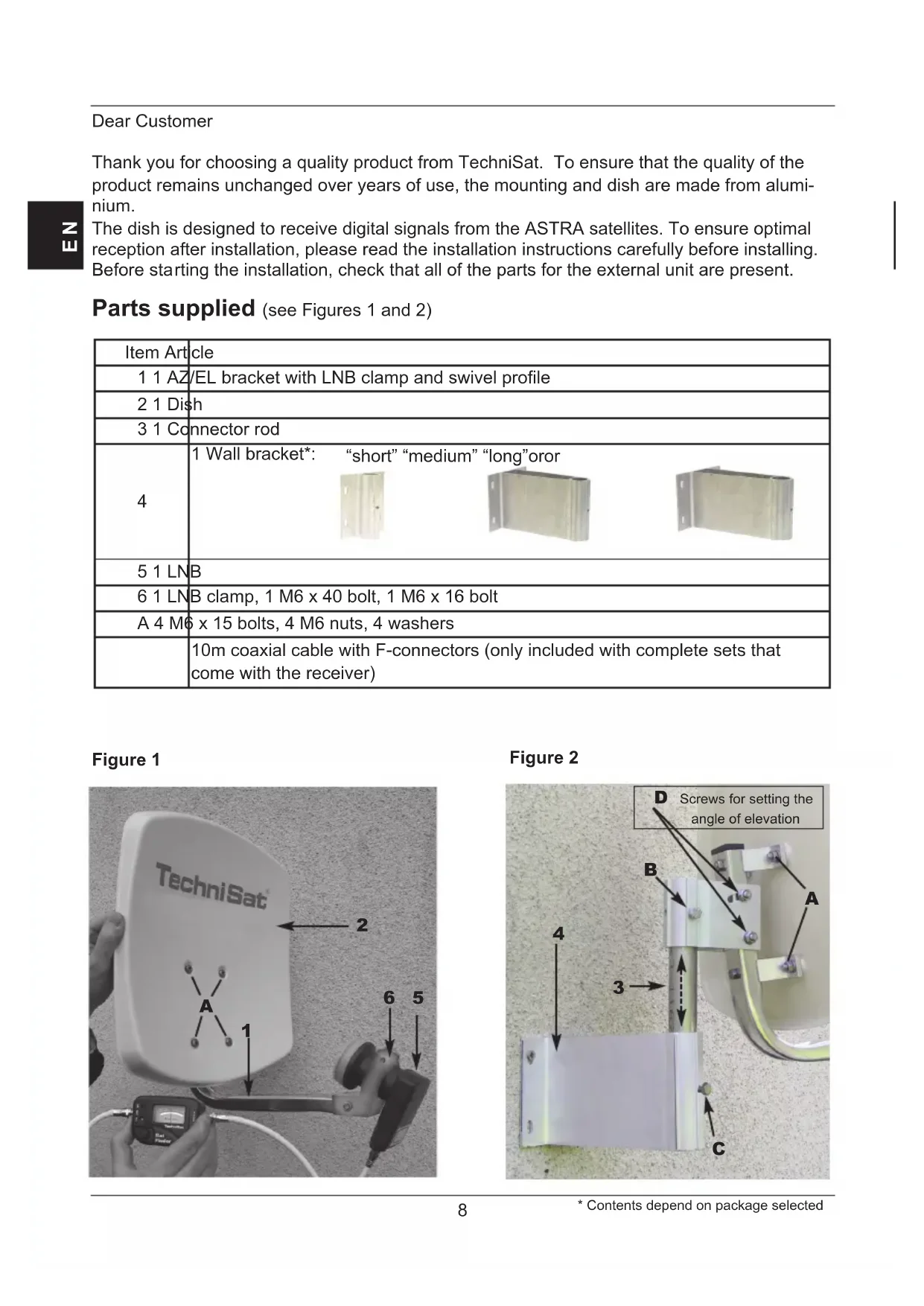
Parts supplied (see Figures 1 and 2)
| Item Article | |||
| 1 1 AZ/EL bracket with LNB clamp and swivel profile | |||
| 2 1 Dish | |||
| 3 1 Connector rod | |||
| 4 | 1 Wall bracket*: “short” “medium” “long”oror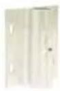 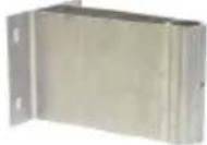 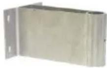 | ||
| 5 1 LNB | |||
| 6 1 LNB clamp, 1 M6 x 40 bolt, 1 M6 x 16 bolt | |||
| A 4 M6 x 15 bolts, 4 M6 nuts, 4 washers | |||
| 10m coaxial cable with F-connectors (only included with complete sets that come with the receiver) | |||
Figure 1
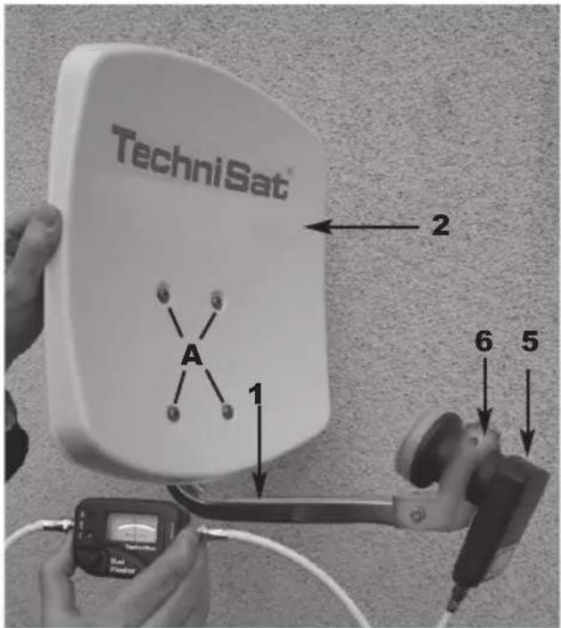
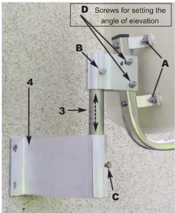
Figure 2
1 Assembling the external unit
The external unit is delivered partially pre-assembled. Only the dish (Item 2) and the connector rod (Item 3) need to be attached.
First, use bolts (A) to attach the dish to the AZ/EL bracket (Item 1). Then loosen screw (B) on the swivel mount to attach the connector rod. After this, install the LNB (Item 5) on the LNB bracket using the LNB clamp (Item 6) as shown in Figure 1.

2 Installation
Selecting a location
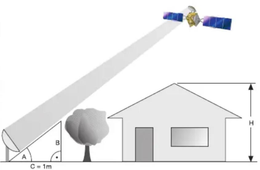
a) Make sure that there is an uninterrupted line of sight from the location in which you are planning to install the dish to the southern sky to enable reception from the position of the ASTRA 19.2° East satellite. You can use the illustration below to verify whether you have left sufficient distance from any nearby obstruction to prevent the obstruction from weakening signal reception. Make sure when installing beneath a terrace that the dish is not within the shadow of any protruding roof.
b) Mount the wall bracket (Item 4) horizontally in the location selected. In order to ensure that the external unit is as securely mounted as possible, you should select the appropriate mounting hardware (scr-ews wall plugs, etc.) for the surface onto which the unit is being installed. Because of the wide variety of wall types, no wall bracket mounting hardware is included.
c) Loosen screw (C) on the wall bracket and attach the external unit using the connector rod.
| Angle A(Elevation) | Gradient B(cm per m) |
| 22° 40.40 | |
| 24° 44.52 | |
| 26° 48.77 | |
| 28° 53.17 | |
| 29° 55.40 | |
| 30° 57.74 | |
| 31° 60.00 | |
| 32° 62.49 | |
| 33° 64.90 | |
| 34° 67.45 | |
| 35° 70.02 | |
| 36° 72.65 | |
| 37° 75.36 | |
| 38° 78.13 |
3 Safety instructions
To ensure electrical safety when performing the installation, follow the applicable European standards and VDE regulations (e.g. VDE 0855, Part 1).
If you are unsure, ask your specialist dealer.
4. Installing the F-connectors
Caution!
Make sure that the receiver equipment is disconnected from the mains when installing the F-connectors.
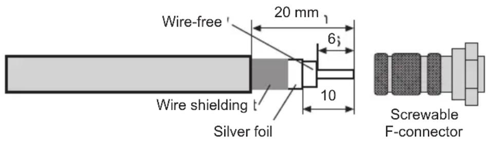
Proceed with extreme caution when installing the F-connectors in order to prevent the satellite receiver from malfunctioning or being damaged irretrievably due to incorrect installation. In addition to the text, please consult Figure 3.
Use a sharp knife to strip the insulation from the end of the cable, leaving 6 mm of the cable core exposed. When stripping the insulation, be sure to avoid damage to the core.
Remove the overlying wire shielding
Now remove 10 mm of the outer plastic sheath to expose the wire shielding. When removing the plastic sheath, be sure to avoid damage to the wire shielding.
Make sure that none of the wires from the shielding are touching the cable core.
Now twist the F-connector carefully onto the cable until the core wire is flush with the front edge of the F-connector.
Finally, check again that none of the wires from the shielding are touching the cable core. The F connector is now correctly installed.
Figure 3
5. Pointing the external unit.
The external unit should be pointed using a meter.
It is also possible to point the unit using the less expensive TechiSat SatFinder (article No. 0000/3045).
Should neither of these be available, the dish can be pointed using a digital receiver and a television as follows.
- Connec t the LNB with the receiver using a suitable coaxial cable.
-
Connect the receiver to the television and set the receiver to a programme channel on which a signal from the desired satellite can be received (e.g. ARD for ASTRA).
-
Select the angle of elevation for your installation location from the AZ/EL table (see section 6). For example, in Daun the angle of elevation for the ASTRA 19.2° East satellite is 31.29°.
Because your external unit has an offset dish, the angle of elevation to be set is not the one you read from the table, but is rather an adjusted angle for the dish. This is calculated as follows:
Angle of elevation minus offset angle = angle to be set.
The offset angle for the DigiDish 33 and the DigiDish 45 is 30^ .
Thus, the angle at which the DigiDish 33 and 45 need to be set in Daun is as follows:
$$ 3 1, 2 9 ^ {\circ} - 3 0 ^ {\circ} = \underline {{1 , 2 9 ^ {\circ}}} $$
- Loosen the screws (D) on the swivel mount so that the external unit can be moved up and down. Place a straight edge over the dish as shown in Figure 4. Set the angle you calculated using an angle gauge.
Figure 4
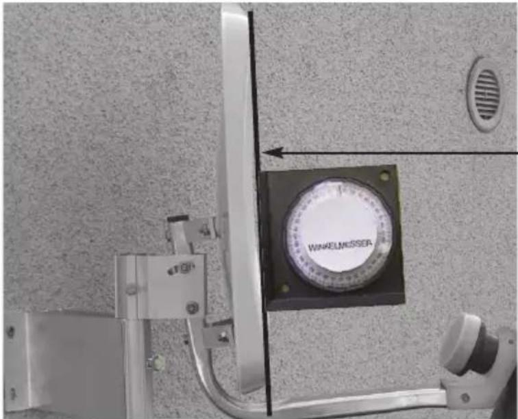
Straight edge used for angle measurement
-
Now loosen screws (C) and (B) on the swivel mount and rotate the dish slowly in the East-West direction (azimuth angle) until you obtain a television picture from the receiver.
-
At this point, the dish still requires fine adjustment. When doing this, it is a good idea to call up the transponder information (see the operating manual for the digital receiver).
-
Then carefully adjust the azimuth (East/West) and elevation angles to obtain the maximum amplitude as indicated on the the level and quality display.
-
Once this is done, tighten all of the screws and make sure that reception does not become worse while you are doing so.
The installation of the dish is now complete and the dish is properly pointed at the desired satellite.
LNB specifications:
Low-band LOF: 9,750 MHz
High-band LOF: 10,600 MHz
Low/high-band switchover: 22 kHz signal from the receiver
Optional accessories:
Pipe bracket for mounting on a mast Art. No.: 0000/0500
Balcony stands Art. No.: 0000/1751
Suction pad bracket Art. No.: 0000/1758
Balcony stands Art. No.: 0000/1755
Concrete slab stands Art. No.: 0000/1756
This product bears the CE symbol and meets all of the required EU standards
Amendments and printing errors reserved. Last updated: 06/12
DigiDish and TechniSat are registered trademarks of
Monday to Friday 08:00 - 18:00
(normal charges will apply for overseas calls)
TechniSat
FR
DIGIDISH 33
DIGIDISH 45
SATMAN 33
SATMAN 45
pour montage mural
asse di misurazione
LOF low-band: 9750 MHz
LOF high-band: 10600 MHz
Bytte mellom low- / high-band: 22kHz-signal fra receiveren
Tilleggsutstyr:
Mastfeste Artikkelnr: 0000/0500
Balkongstativ Artikkelnr: 0000/1751
Sugekoppfeste Artikkelnr: 0000/1758
Balkongstativ Artikkelnr: 0000/1755
LOF High Band 10 600 MHz


- Dear Customer
- Assembling the external unit
- Installation
- Selecting a location
- Safety instructions
- Installing the F-connectors
- Caution!
- Make sure that the receiver equipment is disconnected from the mains when installing the F-connectors.
- Pointing the external unit.
- Angle of elevation minus offset angle = angle to be set.
- LNB specifications:
- Optional accessories:
- TechniSat
- Tilleggsutstyr:
Brand : TECHNISAT
Model : DigiDish 45
Category : Receiver