
A3.610 - Loudspeaker PHILIPS - Free user manual and instructions
Find the device manual for free A3.610 PHILIPS in PDF.
| Product Type | 5.1 Channel Speaker System |
| Brand | Philips |
| Model | A3.610 |
| Input Connectors | Mini DIN 9-pin (5.1), Stereo 3.5 mm, Stereo RCA |
| Speaker Outputs | Center (DIN and 3.5 mm), Rear Right/Left, Front Right/Left |
| Power Supply | AC Mains |
| Remote Control Functions | Standby, Mute, Volume, Front/Rear Fade, Bass/Treble, Flat, Games/Cinema/Music Modes, Input Selection (INPUT 1/2/3) |
| Sound Modes | Games, Cinema, Music |
| Sound Adjustments | Bass, Treble, Flat (over-amplification cancellation) |
| Safety | Do not expose to excessive heat, rain or moisture |
| Cleaning | Soft, lint-free cloth slightly damp, without cleaning products |
| Standby | Use the Standby button on the remote; unplug during prolonged absence |
| Subwoofer Placement | On the floor, near a wall, at least 0.5 m from the TV (not magnetically shielded) |
| Front Speaker Placement | On either side of the TV, at ear level, forming an equilateral triangle with the listener |
| Center Speaker Placement | Near the center of the TV, below or above, facing the listener |
| Surround Speaker Placement | Near the listener, slightly behind, above ear level if close to walls |
Frequently Asked Questions - A3.610 PHILIPS
User questions about A3.610 PHILIPS
0 question about this device. Answer the ones you know or ask your own.
Ask a new question about this device
Download the instructions for your Loudspeaker in PDF format for free! Find your manual A3.610 - PHILIPS and take your electronic device back in hand. On this page are published all the documents necessary for the use of your device. A3.610 by PHILIPS.
USER MANUAL A3.610 PHILIPS
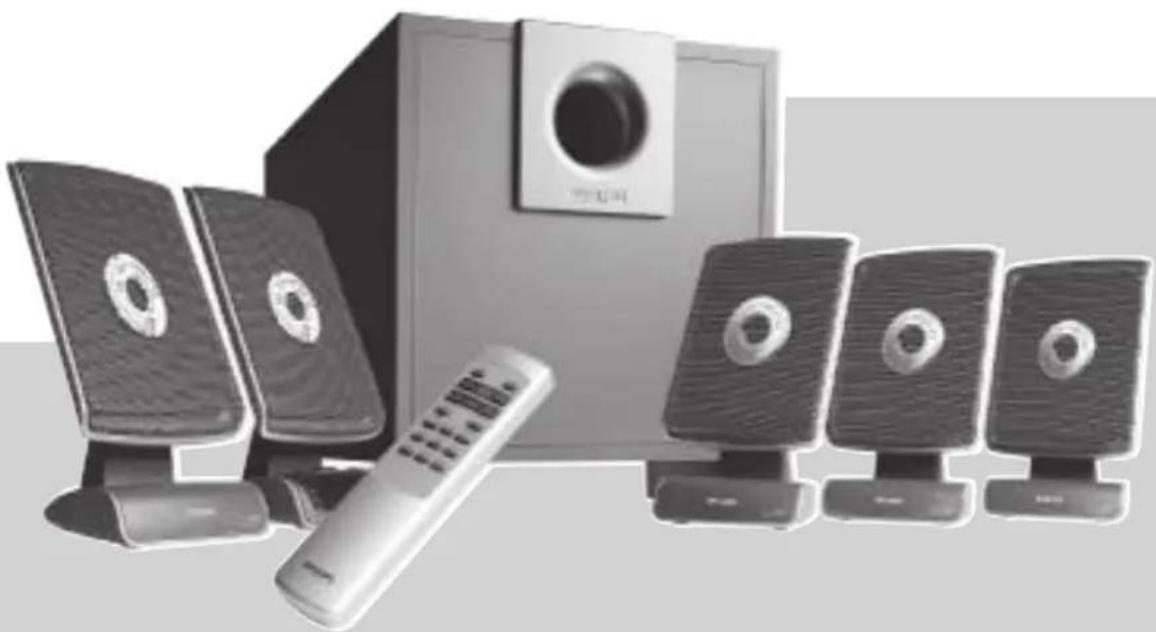
A3.610 Acoustic Fusion/MMS316
natural_image
Exterior view of a modern office setup with speakers, a remote control, and a speaker tower (no visible text or symbols)5.1 Channel Flat Panel Speaker System
Instructions for use 5
Mode d'emploi 8
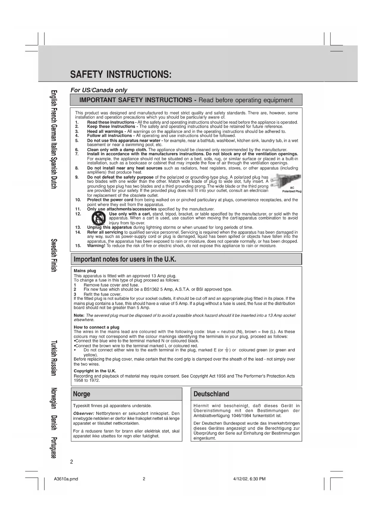
SAFETY INSTRUCTIONS:
For US/Canada only
IMPORTANT SAFETY INSTRUCTIONS - Read before operating equipment
This product was designed and manufactured to meet strict quality and safety standards. There are, however, some installation and operation precautions which you should be particularly aware of.
- Read these instructions - All the safety and operating instructions should be read before the appliance is operated.
- Keep these instructions - The safety and operating instructions should be retained for future reference.
- Heed all warnings - All warnings on the appliance and in the operating instructions should be adhered to.
- Follow all instructions - All operating and use instructions should be followed.
- Do not use this apparatus near water - for example, near a bathtub, washbowl, kitchen sink, laundry tub, in a wet basement or near a swimming pool, etc.
- Clean only with a damp cloth. The appliance should be cleaned only recommended by the manufacturer.
- Install in accordance with the manufacturers instructions. Do not block any of the ventilation openings. For example, the appliance should not be situated on a bed, sofa, rug, or similar surface or placed in a built-in installation, such as a bookcase or cabinet that may impede the flow of air through the ventilation openings.
- Do not install near any heat sources such as radiators, heat registers, stoves, or other apparatus (including amplifiers) that produce heat.
- Do not defeat the safety purpose of the polarized or grounding-type plug. A polarized plug has two blades with one wider than the other. Match wide blade of plug to wide slot, fully insert. A grounding type plug has two blades and a third grounding prong. The wide blade or the third prong are provided for your safety. If the provided plug does not fit into your outlet, consult an electrician for replacement of the obsolete outlet.
- Protect the power cord from being walked on or pinched particularly at plugs, convenience receptacles, and the point where they exit from the apparatus.
- Only use attachments/accessories specified by the manufacturer.
- Use only with a cart, stand, tripod, bracket, or table specified by the manufacturer, or sold with the apparatus. When a cart is used, use caution when moving the cart/apparatus combination to avoid injury from tip-over.
- Unplug this apparatus during lightning storms or when unused for long periods of time.
- Refer all servicing to qualified service personnel. Servicing is required when the apparatus has been damaged in any way, such as power-supply cord or plug is damaged, liquid has been spilled or objects have fallen into the apparatus, the apparatus has been exposed to rain or moisture, does not operate normally, or has been dropped.
- Warning! To reduce the risk of fire or electric shock, do not expose this appliance to rain or moisture.
Polarized Plug
Important notes for users in the U.K.
Mains plug
This apparatus is fitted with an approved 13 Amp plug.
To change a fuse in this type of plug proceed as follows:
1 Remove fuse cover and fuse.
2 Fix new fuse which should be a BS1362 5 Amp, A.S.T.A. or BSI approved type.
3 Refit the fuse cover.
If the fitted plug is not suitable for your socket outlets, it should be cut off and an appropriate plug fitted in its place. If the mains plug contains a fuse, this should have a value of 5 Amp. If a plug without a fuse is used, the fuse at the distribution board should not be greater than 5 Amp.
Note: The severed plug must be disposed of to avoid a possible shock hazard should it be inserted into a 13 Amp socket elsewhere.
How to connect a plug
The wires in the mains lead are coloured with the following code: blue = neutral (N), brown = live (L). As these colours may not correspond with the colour markings identifying the terminals in your plug, proceed as follows:
- Connect the blue wire to the terminal marked N or coloured black.
- Connect the brown wire to the terminal marked L or coloured red.
- Do not connect either wire to the earth terminal in the plug, marked E (or ± ) or coloured green (or green and yellow).
Before replacing the plug cover, make certain that the cord grip is clamped over the sheath of the lead - not simply over the two wires.
Copyright in the U.K.
Recording and playback of material may require consent. See Copyright Act 1956 and The Performer's Protection Acts 1958 to 1972.
Norge
EnglishFrench
Polish Finish Swedish Dutch Spanish Italian German
Portuguese Danish Norwegian Russian Turkish
natural_image
Diagram showing a person sitting at a desk receiving a long beam from a device, with an inset close-up of the device's internal components (no text or symbols present)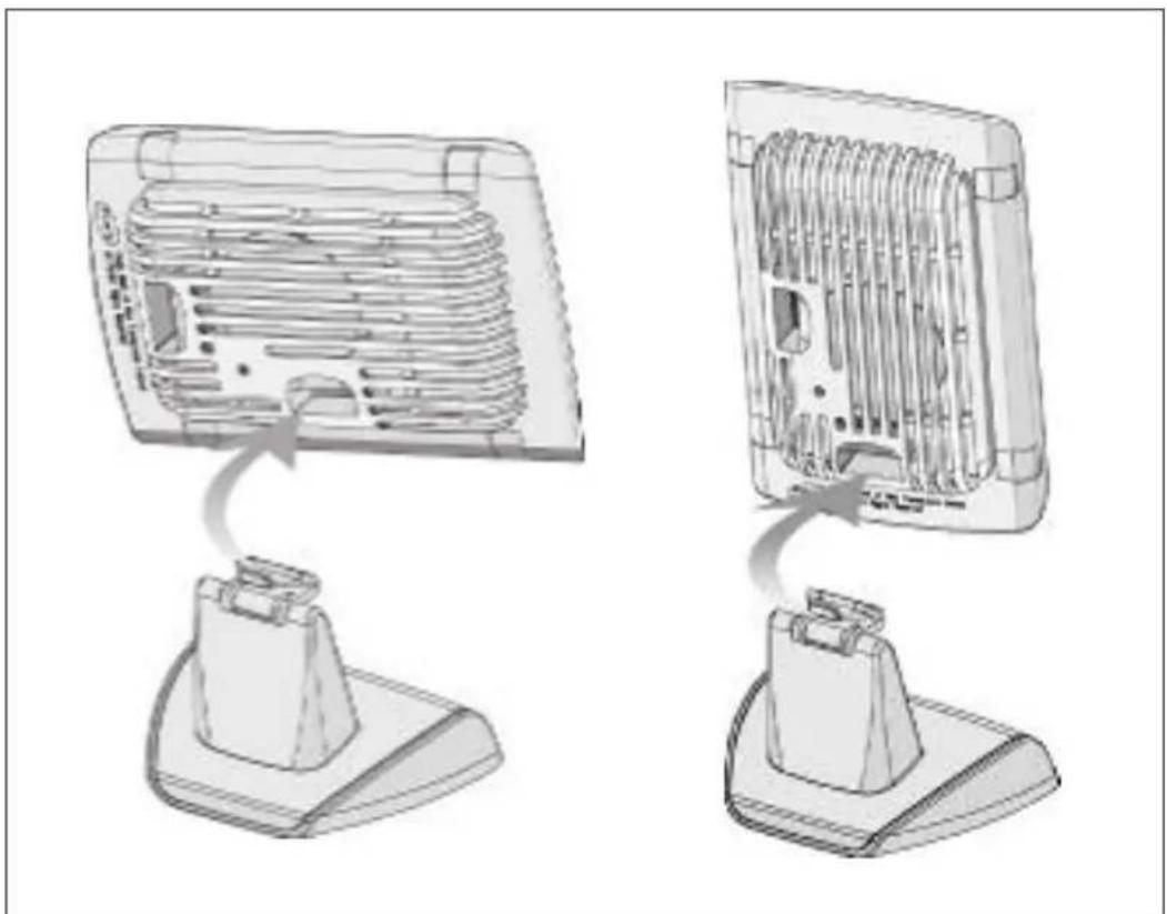
natural_image
Diagram showing two views of a server rack with heat sinks and connectors, no text or symbols presentExplanation (Illustration page 3)
Remote Control (See Illustration A)
①STANDBY
To switch the speaker system into ON or OFF (=STANDBY) mode
② MUTE
To switch the speaker system into mute mode, and normal mode again
③MASTER VOLUME - / +
To adjust the master volume higher or lower
④FADE REAR / FRONT
To adjust the loudness of the rear and the front satellite speakers
⑤BASS - / +
To adjust the bass level according your personal preference
⑥ TREBLE - / +
To adjust the presence of the higher tones according to your personal preference
⑦FLAT
Removes any bass or treble boost applied by the user.
⑧GAME/ MOVIE/ MUSIC
Choose from either the game, movie or music button for optimal pre-set sound reproduction per genre. Movie will upmix all stereo sources (e.g.) TV into 5.1 channel surround sound.
⑨INPUT 1/ INPUT 2/ INPUT 3
Make your choice of audio-visual source selection. Two separate stereo input sources and one 5.1-channel input source can be connected to this multi-channel speaker system.
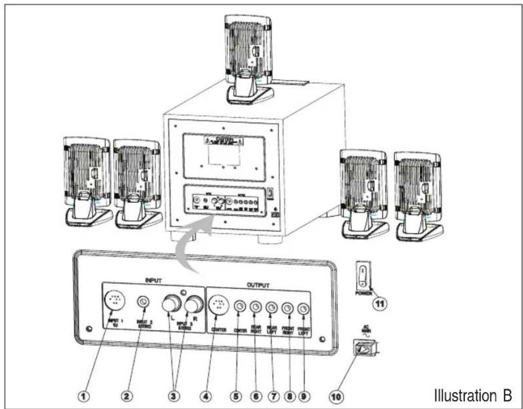
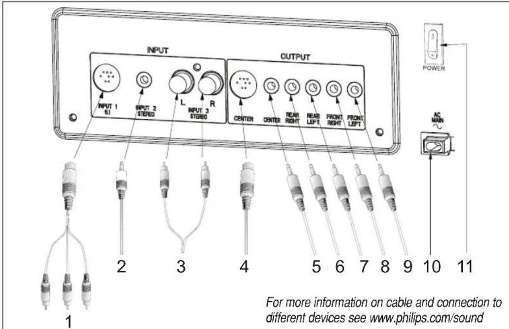
Cable Connections (see illustration B)
Inputs
1. INPUT 1 : 5.1-channel
9 pin mini DIN cable to connect a 5.1-channel audio-visual source.
2. INPUT 2 : STEREO CHANNEL
3.5 mm stereo jack to connect a stereo audio-visual source
3. INPUT 3 : STEREO CHANNEL
2 x RCA jack to connect a stereo audio-visual source.
Output
4. CENTER
To connect the center satellite speaker. (DIN jack)
5. C ENTER
To connect the center satellite speaker. (3.5mm stereo jack)
6. R EAR RIGHT
To connect the rear right satellite speaker.
7. REAR LEFT
To connect the rear left satellite speaker.
8. FRONT RIGHT
To connect the front right satellite speaker.
9. FRONT LEFT
To connect the front left satellite speaker.
10. AC MAIN
Power cable to be connected to the AC outlet.
11. P OWER SWITCH
Turn the system power on and off. Switch to the off position if the system will not be used for long periods to reduce power consumption.
Connecting to a 5.1 channel soundcard (or a DVD player with built in 5.1 channel decoder - cable not included)
- Connect the 9 pin mini DIN jack to the speaker system and the 3 mini stereo jacks to the soundcard.
Connecting External Stereo Sources (cables not included)
- Connect the mini stereo jack to a source such as an MP3 player headphone jack.
- Connect the RCA stereo jacks to a source such as a TV.
Satellite Speaker Connection
- Connect the center satellite speaker to CENTER. (DIN jack)
- Connect the center satellite speaker to CENTER. (3.5 mm stereo jack)
- Connect the rear right satellite speaker to REAR RIGHT.
- Connect the rear left satellite speaker to REAR LEFT.
- Connect the front right satellite speaker to FRONT RIGHT.
- Connect the front left satellite speaker to FRONT LEFT.
Power Connection
- Connect the fixed mains power code to the AC outlet.
Switch on (and switch off as well) the speaker system using the standby button on the remote control.
Tune the speaker system using the speaker settings at the remote control.
NOTE!
Do not insert the power plug into the AC outlet until all the connections are made!
Safety
- Do not expose the speakers to excessive heat (caused by heating equipment or direct sunlight). To reduce the risk of fire or electric shock, do not expose this appliance to rain or moisture. If fluid spills into the speakers, disconnect any connections immediately and let the speakers dry before reusing them.
- You may clean the speakers with a soft, slightly dampened lint-free cloth. Do not use any cleaning agents as they may have a corrosive effect.
- If the speakers do not operate, disconnect them from the power supply. Wait a few seconds before reconnecting them to the power supply.
- If your intentions are not to use the speaker system for a longer period of time - for example, you're going on a vacation - it is recommended to switch off the system completely and not to leave it in standby mode.
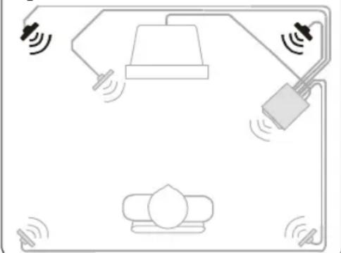
Speaker Placement -
General
- Placing speakers behind curtains, furniture, or any other objects will reduce the treble response, thus reducing the stereo effect significantly.
• Each room has different acoustic characteristics and the placement possibilities are often limited. You can find the best position for your speakers by experimenting. In general, the speakers should be placed as symmetrical as possible in the room.
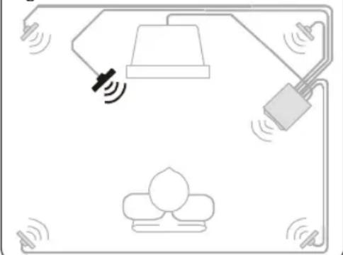
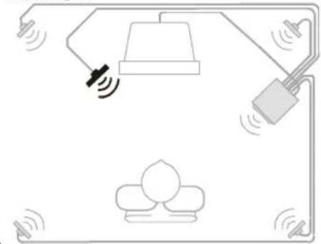
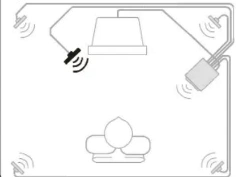
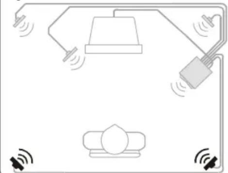
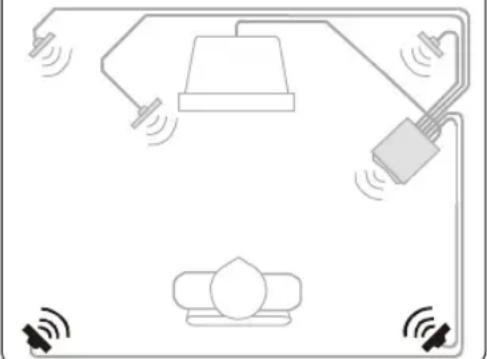
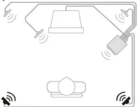
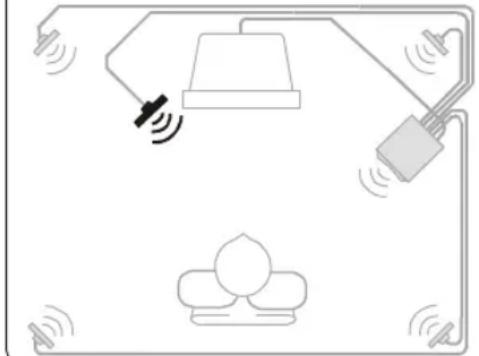
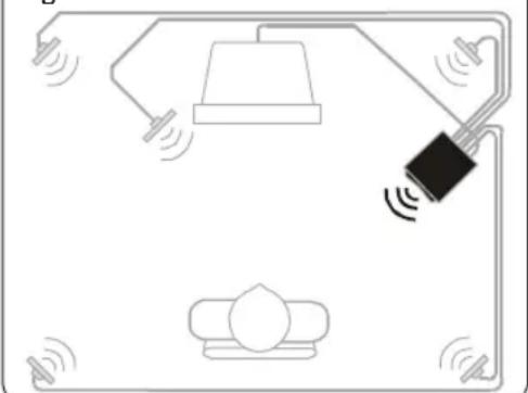
Front Satellite Speakers (figure a)
- The front left and right satellite speaker play stereo music and the off-screen sounds of video playback.
• These satellites should be placed to the sides of your TV.
• Viewed from the listener's position, the satellite speaker connected to Front Left at the subwoofer should be on the left side, and the satellite speaker connected to Front Right at the subwoofer should be on the right side. - The best stereo effect is obtained when the two front satellite speakers and the listener form an equilateral triangle.
- The optimum height for these speakers is when they are placed at ear height (while seated).
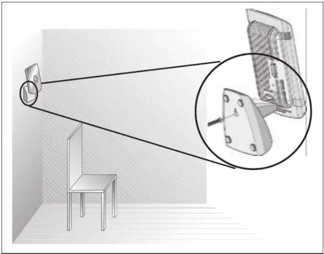
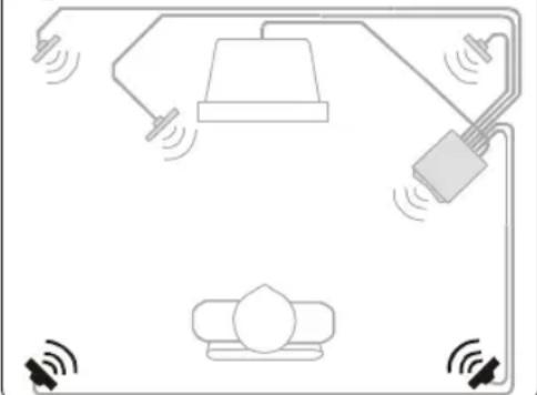
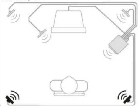
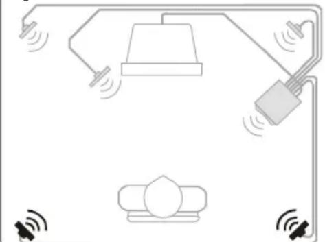
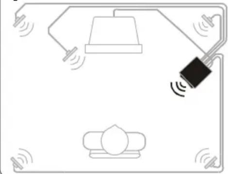
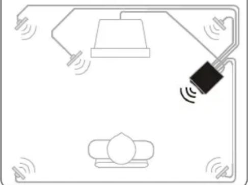
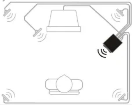
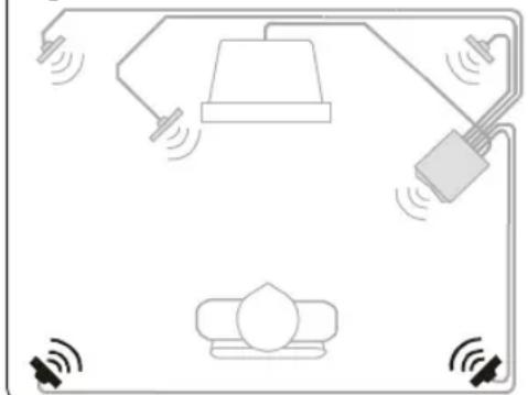
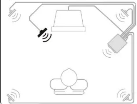
Center Satellite Speaker (figure b)
- The center satellite speaker provides the on-screen effects and dialog in Dolby Digital / Dolby Surround.
- It should be placed as close to the center of your TV as possible (e.g. underneath or on top of your TV).
- It should be directed at the listener's ear level while seated.
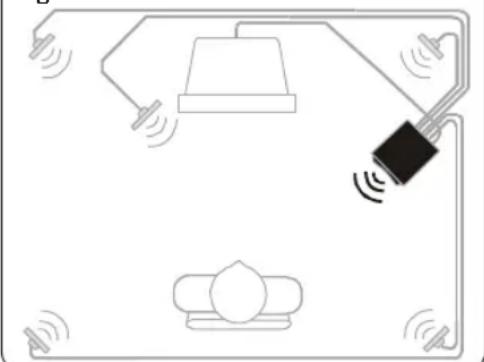
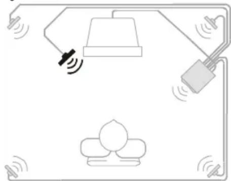
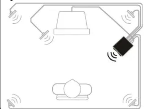
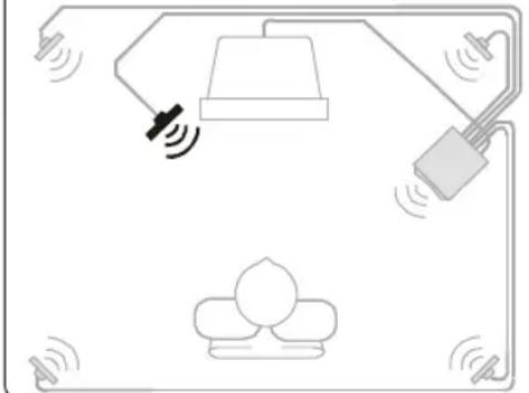
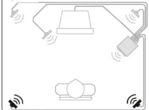
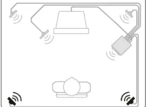
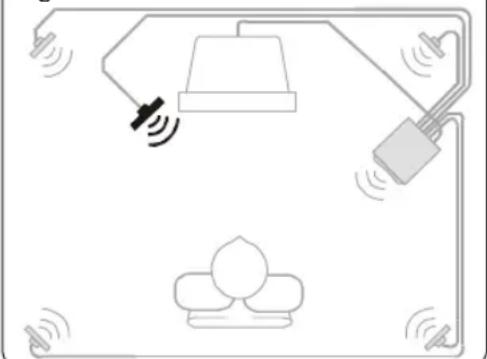
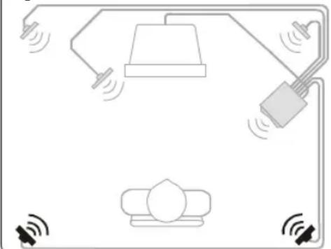
Surround Satellite Speakers (figure c)
• The surround left and right satellite speaker provide the surround effects in Dolby Digital / Dolby Surround
- These satellites may be placed in any convenient sites alongside the listener, even sites slightly forward the listener's position.
- The surround satellite speakers do not have to be at exactly the same height as the front satellite speakers.
• Viewed from the listener's position, the satellite speaker connected to Rear Left at the subwoofer should be on the left side, and the satellite speaker connected to Rear Right at the subwoofer should be on the right side.
- If you have side walls close to your listening position, good placement for your surround satellites is slightly behind your position and slightly above ear level.
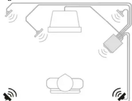
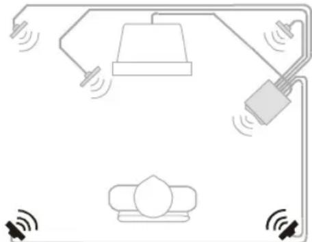
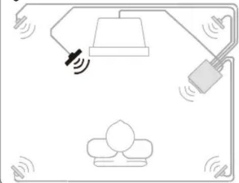
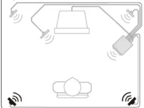
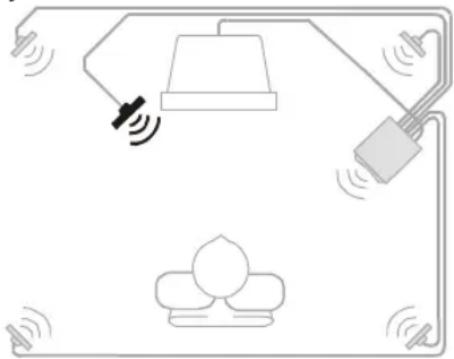
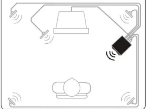
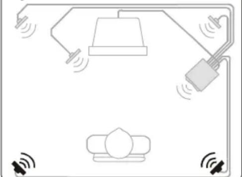
Subwoofer (figure d)
- The subwoofer's optimum place is on the floor close to the wall. The closer it is to the corner, the stronger the maximum bass output.
- The subwoofer is not magnetically shielded, so position it at least 0.5 meter from the TV.
Figure a:
natural_image
Diagram of a smart home control system with sensors, lighting, and a central device (no text or labels)Figure b:
natural_image
Diagram of a smart home control system with sensors and a central device (no text or labels)Figure c:
natural_image
Diagram of a smart home control system with lighting, sensors, and equipment (no text or labels)Figure d:
natural_image
Simple line drawing of a room layout with lighting fixtures and a central device (no text or symbols)Subwoofer (figure d)
natural_image
Simple line drawing of a smart home control system with no text or symbolsFigure b:

natural_image
Simple line drawing of a lamp connected to a wall-mounted device, with no text or symbols present.Figure c:
natural_image
Pure electrical circuit lines without any symbolsFigure d:

natural_image
Simple line drawing of a smart home control system with a lamp, sensor, and device (no text or symbols)natural_image
Simple line drawing of a ceiling-mounted device with sensors and a lamp, no text or symbols presentAbbildung b:
natural_image
Simple line drawing of a lamp and hanging device with sound waves, no text or symbols presentAbbildung c:
natural_image
Simple line drawing of a smart home control system with speakers, lamp, and wall-mounted sensors (no text or symbols)Abbildung d:

natural_image
Simple line drawing of a room layout with lighting and sound waves (no text or symbols)natural_image
Simple line drawing of a lamp, hanging device, and floor with sound waves (no text or symbols)Figura b:
natural_image
Simple line drawing of a lamp connected to a wall-mounted device with sound waves, no text or symbols present.Figura c:
natural_image
Diagram of a smart home control system with lighting, sensors, and a device (no text or symbols)Figura d:

natural_image
Simple line drawing of a smart home control system with a lamp, sensor, and wall-mounted device (no text or symbols)natural_image
Diagram of a smart home control system with lamp, switch, and sensors (no text or labels)Figura b:
natural_image
Diagram of a smart home control system with hanging lamp, sensor, and wall-mounted device (no text or symbols)Figura c:
natural_image
Diagram of a smart home control system with hanging lamp, power cord, and sensors (no text or labels)Figura d:
natural_image
Simple line drawing of a smart home control system with a lamp, switch, and sofa (no text or symbols)natural_image
Simple line drawing of a lamp, hanging device, and floor with sound waves (no text or symbols)Figuur b:
natural_image
Simple line drawing of a lamp and hanging device with sound waves, no text or symbols presentFiguur c:
natural_image
Simple line drawing of a smart home control system with lighting, sensors, and a device (no text or symbols)Figuur d:
natural_image
Simple line drawing of a lamp connected to a black sensor device, with no text or symbols present.- INPUT 1: 5.1-KANALS,
natural_image
Simple line drawing of a ceiling-mounted device with sensors and a lamp, no text or symbols presentFigur b:
natural_image
Diagram of a smart home control system with lighting, sensors, and equipment (no text or symbols)Figur c:
natural_image
Diagram of a smart home control system with lighting, sensors, and a device (no text or symbols)Figur d:

natural_image
Simple line drawing of a lamp connected to a wall-mounted device, with no text or symbols present.2. INPUT 2: stereo channel
3. INPUT 3: stereo channel
natural_image
Diagram of a smart home control system with sensors, lamp, and wall-mounted device (no text or labels)Kuva b:

natural_image
Simple line drawing of a lamp connected to a wall-mounted device with sound waves, no text or symbols present.Kuva c:
natural_image
Diagram of a smart home control system with lighting and sensors (no text or symbols)Kuva d:
natural_image
Simple line drawing of a room layout with lighting fixtures and a hanging device (no text or symbols)① STANDBY (CZEKIWANIE)
natural_image
Simple line drawing of a room layout with lighting fixtures and sound waves (no text or symbols)Rys. b:

natural_image
Simple line drawing of a lamp and hanging device with sound waves, no text or symbols presentRys. c:
natural_image
Simple line drawing of a smart home control system with lighting, sensors, and a sofa (no text or symbols)Rys. d:

natural_image
Simple line drawing of a lamp connected to a black sensor device, with no text or symbols present.中文
EnglishFrench
Polish Finish Swedish Dutch Spanish Italian German
中文
natural_image
Simple line drawing of a room layout with lighting and sound waves (no text or symbols)Şekil b:
natural_image
Simple line drawing of a lamp connected to a wall-mounted device, with no text or symbols present.Şekil c:
natural_image
Diagram of a smart home control system with lighting, sensors, and a device (no text or symbols)Şekil d:
natural_image
Simple line drawing of a smart home control system with a lamp, switch, and sofa (no text or symbols)natural_image
Simple line drawing of a room layout with lighting fixtures and sound waves (no text or symbols)Рис. b:

natural_image
Simple line drawing of a lamp and hanging device with sound waves, no text or symbols presentРис. с:
natural_image
Diagram of a smart home control system with lighting, sensors, and a device (no text or symbols)Рис. d:
natural_image
Simple line drawing of a lamp connected to a device with sound waves, no text or symbols presentForklaring (se figur på side 3)
Fjernkontroll (Se figur A)
①STANDBY
natural_image
Simple line drawing of a room layout with lighting fixtures and sound waves (no text or symbols)Figur b:
natural_image
Simple line drawing of a lamp connected to a wall-mounted device, with no text or symbols present.Figur c:
natural_image
Simple line drawing of a smart home control system with lamp, wall-mounted device, and sensors (no text or symbols)Figur d:

natural_image
Simple line drawing of a lamp connected to a device with sound waves, no text or symbols presentnatural_image
Diagram of a smart home control system with lighting, sensors, and equipment (no text or symbols)Figur b:
natural_image
Diagram of a smart home control system with sensors and lighting components (no text or labels)Figure c:
natural_image
Diagram of a smart home control system with lighting, sensors, and equipment (no text or labels)Figur d:
natural_image
Simple line drawing of a smart home control system with a lamp, sensor, and wall-mounted device (no text or symbols)natural_image
Simple line drawing of a ceiling lamp connected to a wall-mounted device, with no text or symbols present.Figura b:
natural_image
Simple line drawing of a lamp and hanging device with sound waves, no text or symbols presentFigura c:
natural_image
Diagram of a smart home control system with lighting, sensors, and a device (no text or symbols)Figura d:

natural_image
Simple line drawing of a lamp and hanging device with sound waves, no text or symbols presentPHILIPS CONSUMER ELECTRONICS COMPANY
A Division of Philips Electronics North America Corporation Knoxville, Tennessee 37914-1810, U.S.A.
www.pcsound.philips.com
www.philips.com/sound
www.philips.com

4399 294 60521
Printed in Malaysia
- Channel Flat Panel Speaker System
- SAFETY INSTRUCTIONS:
- For US/Canada only
- IMPORTANT SAFETY INSTRUCTIONS - Read before operating equipment
- Important notes for users in the U.K.
- Mains plug
- How to connect a plug
- Copyright in the U.K.
- Norge
- Explanation (Illustration page 3)
- Remote Control (See Illustration A)
- ①STANDBY
- ② MUTE
- ③MASTER VOLUME - / +
- ④FADE REAR / FRONT
- ⑤BASS - / +
- ⑥ TREBLE - / +
- ⑦FLAT
- ⑧GAME/ MOVIE/ MUSIC
- ⑨INPUT 1/ INPUT 2/ INPUT 3
- Cable Connections (see illustration B)
- Inputs
- INPUT 1 : 5.1-channel
- INPUT 2 : STEREO CHANNEL
- INPUT 3 : STEREO CHANNEL
- Output
- CENTER
- C ENTER
- R EAR RIGHT
- REAR LEFT
- FRONT RIGHT
- FRONT LEFT
- AC MAIN
- P OWER SWITCH
- Connecting to a 5.1 channel soundcard (or a DVD player with built in 5.1 channel decoder - cable not included)
- Connecting External Stereo Sources (cables not included)
- Satellite Speaker Connection
- Power Connection
- NOTE!
- Safety
- Speaker Placement -
- General
- Front Satellite Speakers (figure a)
- Center Satellite Speaker (figure b)
- Surround Satellite Speakers (figure c)
- Subwoofer (figure d)
- INPUT 2: stereo channel
- INPUT 3: stereo channel
- Forklaring (se figur på side 3)
- Fjernkontroll (Se figur A)
- PHILIPS CONSUMER ELECTRONICS COMPANY
Brand : PHILIPS
Model : A3.610
Category : Loudspeaker