MXZ-4D83VA MXZ-5D102VA - Air conditioner outdoor unit MITSUBISHI ELECTRIC - Free user manual and instructions
Find the device manual for free MXZ-4D83VA MXZ-5D102VA MITSUBISHI ELECTRIC in PDF.
User questions about MXZ-4D83VA MXZ-5D102VA MITSUBISHI ELECTRIC
0 question about this device. Answer the ones you know or ask your own.
Ask a new question about this device
Download the instructions for your Air conditioner outdoor unit in PDF format for free! Find your manual MXZ-4D83VA MXZ-5D102VA - MITSUBISHI ELECTRIC and take your electronic device back in hand. On this page are published all the documents necessary for the use of your device. MXZ-4D83VA MXZ-5D102VA by MITSUBISHI ELECTRIC.
USER MANUAL MXZ-4D83VA MXZ-5D102VA MITSUBISHI ELECTRIC
Split-type Air-Conditioner
MXZ-4D83VA
MXZ-5D102VA
English is original.
Installation Manual
- This manual only describes the installation of outdoor unit.
When installing the indoor unit, refer to the installation manual of indoor unit.
Required Tools for Installation
Phillips screwdriver
Flare tool for R410A
Level
Gauge manifold for R410A
Scale
Utility knife or scissors
Torque wrench
Wrench (or spanner)
4 mm hexagonal wrench
1. BEFORE INSTALLATION
1-1. THE FOLLOWING SHOULD ALWAYS BE OBSERVED FOR SAFETY
- Be sure to read "THE FOLLOWING SHOULD ALWAYS BE OBSERVED FOR SAFETY" before installing the air conditioner.
- Be sure to observe the warnings and cautions specified here as they include important items related to safety.
After reading this manual, be sure to keep it together with the OPERATING INSTRUCTIONS for future reference. - Equipment complying with IEC/EN 61000-3-12.
WARNING (Could lead to death, serious injury, etc.)
■ Do not install the unit by yourself (user).
Incomplete installation could cause fire or electric shock, injury due to the unit falling, or leakage of water. Consult the dealer from whom you purchased the unit or a qualified installer.
- Perform the installation securely referring to the installation manual. Incomplete installation could cause fire, electric shock, injury due to the unit falling, or leakage of water.
- When installing the unit, use appropriate protective equipment and tools for safety.
Failure to do so could cause injury.
Install the unit securely in a place which can bear the weight of the unit. If the installation location cannot bear the weight of the unit, the unit could fall causing injury.
Electrical work should be performed by a qualified, experienced electrician, according to the installation manual. Be sure to use an exclusive circuit. Do not connect other electrical appliances to the circuit.
If the capacity of the power circuit is insufficient or there is incomplete electrical work, it could result in a fire or an electric shock.
- Do not damage the wires by applying excessive pressure with parts or screws.
Damaged wires could cause fire or electric shock.
■ Be sure to cut off the main power in case of setting up the indoor P.C. board or wiring works.
Failure to do so could cause electric shock. - Use the specified wires to connect the indoor and outdoor units securely and attach the wires firmly to the terminal block connecting sections so the stress of the wires is not applied to the sections. Do not extend the wires, or use intermediate connection. Incomplete connecting and securing could cause fire.
- Do not install the unit in a place where inflammable gas may leak. If gas leaks and accumulates in the area around the unit, it could cause an explosion.
- Do not use intermediate connection of the power cord or the extension cord and do not connect many devices to one AC outlet. It could cause a fire or an electric shock due to defective contact, defective insulation, exceeding the permissible current, etc.
■ Be sure to use the parts provided or specified parts for the installation work.
The use of defective parts could cause an injury or leakage of water due to a fire, an electric shock, the unit falling, etc.
- When plugging the power supply plug into the outlet, make sure that there is no dust, clogging, or loose parts in both the outlet and the plug. Make sure that the power supply plug is pushed completely into the outlet.
If there is dust, clogging, or loose parts on the power supply plug or the outlet, it could cause electric shock or fire. If loose parts are found on the power supply plug, replace it.
- Attach the electrical cover to the indoor unit and the service panel to the outdoor unit securely.
If the electrical cover of the indoor unit and/or the service panel of the outdoor unit are not attached securely, it could result in a fire or an electric shock due to dust, water, etc. - When installing, relocating, or servicing the unit, make sure that no substance other than the specified refrigerant (R410A) enters the refrigerant circuit.
Any presence of foreign substance such as air can cause abnormal pressure rise and may result in explosion or injury. The use of any refrigerant other than that specified for the system will cause mechanical failure, system malfunction, or unit breakdown. In the worst case, this could lead to a serious impediment to securing product safety. - Do not discharge the refrigerant into the atmosphere. If refrigerant leaks during installation, ventilate the room.
If refrigerant comes in contact with a fire, harmful gas could be generated. Refrigerant leakage may cause suffocation. Provide ventilation in accordance with EN378-1.
Check that the refrigerant gas does not leak after installation has been completed.
If refrigerant gas leaks indoors, and comes into contact with the flame of a fan heater, space heater, stove, etc., harmful substances will be generated.
Use appropriate tools and piping materials for installation.
The pressure of R410A is 1.6 times more than R22. Not using appropriate tools or materials and incomplete installation could cause the pipes to burst or injury. - When pumping down the refrigerant, stop the compressor before disconnecting the refrigerant pipes.
If the refrigerant pipes are disconnected while the compressor is running and the stop valve is open, air could be drawn in and the pressure in the refrigeration cycle could become abnormally high. This could cause the pipes to burst or injury. - When installing the unit, securely connect the refrigerant pipes before starting the compressor.
If the compressor is started before the refrigerant pipes are connected and when the stop valve is open, air could be drawn in and the pressure in the refrigeration cycle could become abnormally high. This could cause the pipes to burst or injury. - Fasten a flare nut with a torque wrench as specified in this manual. If fastened too tight, a flare nut may break after a long period and cause refrigerant leakage.
The unit shall be installed in accordance with national wiring regulations.
Earth the unit correctly.
Do not connect the earth to a gas pipe, water pipe, lightning rod or telephone earth. Defective earthing could cause electric shock.
CAUTION (Could lead to serious injury in particular environments when operated incorrectly.)
Install an earth leakage breaker depending on the installation place. If an earth leakage breaker is not installed, it could cause electric shock.
Perform the drainage/piping work securely according to the installation manual.
If there is defect in the drainage/piping work, water could drop from the unit, soaking and damaging household goods.
- Do not touch the air inlet or the aluminum fins of the outdoor unit. This could cause injury.
- Do not install the outdoor unit where small animals may live. If small animals enter and touch the electric parts inside the unit, it could cause a malfunction, smoke emission, or fire. Also, advise user to keep the area around the unit clean.
1-2. SPECIFICATIONS
| Model | Power supply *1 | Wire specifications *2 | Pipe length and height difference *3, *4, *5, *6, *7, *8 | ||||||
| Rated Voltage | Frequency | Breaker capacity | Power supply | Indoor/outdoor connecting wire | Max. pipe length per indoor unit / for multi-system | Max. height difference *9 | Max. no. of bends per indoor unit / for multi system | Refrigerant adjust-ment A *10 | |
| MXZ-4D83VA | 230 V | 50 Hz | 25 A | 3-core 2.5 mm² | 4-core 1.0 / 1.5 mm² | 25 m / 70 m | 15 m | 25 / 70 | 20 g/m |
| MXZ-5D102VA | 25 m / 80 m | 15 m | 25 / 80 | ||||||
1 Connect to the power switch which has a gap of 3mm or more when open to interrupt the source power phase. (When the power switch is shut off, it must interrupt all phases.)
2 Use wires in conformity with design 60245 IEC 57. Use the indoor/outdoor connecting wire in conformity with the wire specifications specified in the installation manual of the indoor unit.
3 Never use pipes with thickness less than specified. The pressure resistance will be insufficient.
4 Use a copper pipe or a copper-alloy seamless pipe.
*5 Be careful not to crush or bend the pipe during pipe bending.
6 Refrigerant pipe bending radius must be 100 mm or more.
7 Insulation material : Heat resisting foam plastic 0.045 specific gravity
8 Be sure to use the insulation of specified thickness. Excessive thickness may cause incorrect installation of the indoor unit and insufficient thickness may cause dew drippage.
9 If the outdoor unit is installed higher than the indoor unit, max. height difference is reduced to 10m .
*10 If pipe length exceeds 40 m, additional refrigerant (R410A) charge is required. (No additional charge is required for pipe length less than 40 m.) Additional refrigerant = A × (pipe length (m) - 40)
1-3. SELECTING OPTIONAL DIFFERENT-DIAMETER JOINTS
If the diameter of connection pipe does not match the port size of outdoor unit, use optional different-diameter joints according to the following table.
(Unit: mm (inch))
| Port size of outdoor unit | Optional different-diameter joints (port size of outdoor unit → diameter of connection pipe) | ||
| MXZ-4D83VA | MXZ-5D102VA | Liquid / Gas | 6.35 (1/4) → 9.52 (3/8) : PAC-493PI9.52 (3/8) → 12.7 (1/2) : MAC-A454JP |
| A UNIT | 6.35 (1/4) / 12.7 (1/2) | 9.52 (3/8) → 15.88 (5/8) : PAC-SG76RJ12.7 (1/2) → 9.52 (3/8) : MAC-A455JP12.7 (1/2) → 15.88 (5/8) : MAC-A456JP | |
| B - D UNIT | B - E UNIT | 6.35 (1/4) / 9.52 (3/8) | Refer to the installation manual of indoor unit for the diameter of connection pipe of indoor unit. |
1-4. SELECTING THE INSTALLATION LOCATION
- Where it is not exposed to strong wind.
Where airflow is good and dustless. - Where rain or direct sunshine can be avoided as much as possible.
- Where neighbours are not annoyed by operation sound or hot air
- Where rigid wall or support is available to prevent the increase of operation sound or vibration.
- Where there is no risk of combustible gas leakage.
- When installing the unit, be sure to secure the unit legs.
- Where it is at least 3m away from the antenna of TV set or radio. Operation of the air conditioner may interfere with radio or TV reception in areas where reception is weak. An amplifier may be required for the affected device.
Install the unit horizontally. - Please install it in an area not affected by snowfall or blowing snow. In areas with heavy snow, please install a canopy, a pedestal and/or some baffle boards.
Note:
It is advisable to make a piping loop near outdoor unit so as to reduce vibration transmitted from there.
Note:
When operating the air conditioner in low outside temperature, be sure to follow the instructions described below.
- Never install the outdoor unit in a place where its air inlet/outlet side may be exposed directly to wind.
- To prevent exposure to wind, install the outdoor unit with its air inlet side facing the wall.
- To prevent exposure to wind, it is recommended to install a baffle board on the air outlet side of the outdoor unit.
Avoid the following places for installation where air conditioner trouble is liable to occur.
- Where flammable gas could leak.
- Where there is much machine oil.
- Where oil is splashed or where the area is filled with oily smoke (such as cooking areas and factories, in which the properties of plastic could be changed and damaged).
- Salty places such as the seaside.
- Where sulfide gas is generated such as a hot spring.
- Where there is high-frequency or wireless equipment
- Where there is emission of high levels of VOCs, including phthalate compounds, formaldehyde, etc., which may cause chemical cracking.
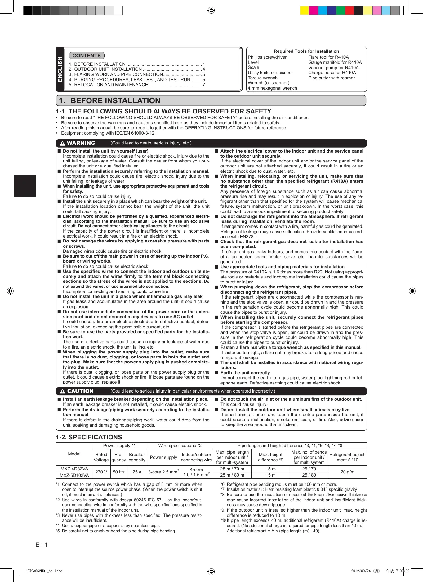
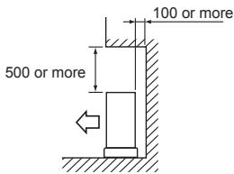
FREE SPACE REQUIRED AROUND OUTDOOR UNIT
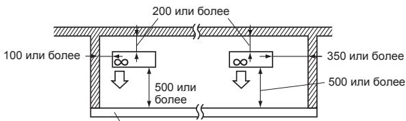
1. Obstacles above
When there is no obstacle in front and on the sides of the unit, it is allowed to install the unit where an obstacle is above the unit only if the space shown in the figure is provided.
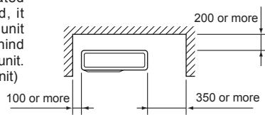
3. Obstacles in front (blowing) only
When there is an obstacle in front of the unit as shown in the figure, open space above, behind, and on the sides of the unit is required.
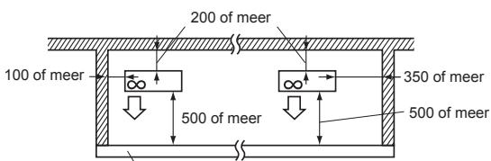
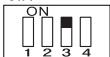
5. Obstacles in front, behind and on side(s)
- When installing the unit in an area that is enclosed with walls such as a verandah, be sure to have enough space as shown below. In this case, the air conditioning capacity and power consumption might deteriorate.
- When there is a lack of airflow or there is a possibility of becoming short cycle, install an outlet guide and make sure there is enough space behind of the unit.
- When installing two or more units, do not install the units in front or behind each other.
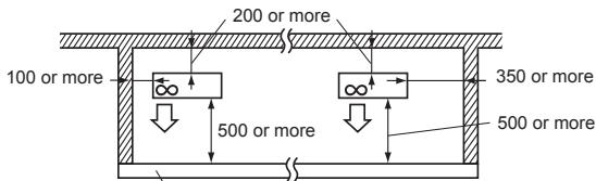
Height of the obstacle is 1200 or less
2. Front (blowing) side open
As long as space indicated in the figure is provided, it is allowed to install the unit where obstacles are behind and on the sides of the unit. (No obstacle above the unit)
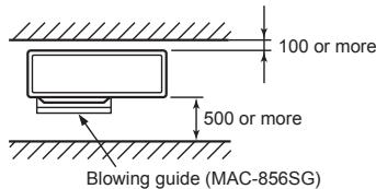
4. Obstacles in front and behind
The unit can be used by attaching an optional outdoor blowing guide (MAC-856SG) (but both sides and top are open).
6. Service space
Provide space for service and maintenance as shown in the figure.
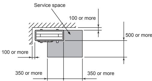
(Unit: mm)

Units should be installed by licensed contractor according to local code requirements.
ACCESSIONS
Check the following parts before installation.
| (1) | Drain socket | 1 |
PARTS TO BE PROVIDED AT YOUR SITE
| (A) | Power supply cord* | 1 |
| (B) | Indoor/outdoor unit connecting wire* | 1 |
| (C) | Extension pipe | 1 |
| (D) | Wall hole cover | 1 |
| (E) | Piping tape | 1 |
| (F) | Extension drain hose (or soft PVC hose, 15 mm inner diameter or hard PVC pipe VP16) | 1 |
| (G) | Refrigeration oil | Little amount |
| (H) | Putty | 1 |
| (I) | Pipe fixing band | 2 to 7 |
| (J) | Fixing screw for (I) | 2 to 7 |
| (K) | Wall hole sleeve | 1 |
| (L) | Soft PVC hose, 15 mm inner di-ameter or hard PVC pipe VP16 for drain socket (1) | 1 |
* Note:
Place indoor/outdoor unit connecting wire (B) and power supply cord (A) at least 1 m away from the TV antenna wire.
The "Q'ty" for (B) to (K) in the above table is quantity to be used per indoor unit.
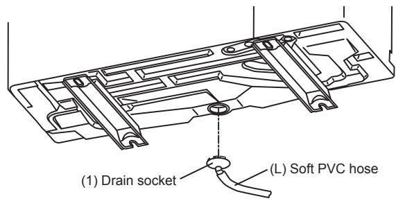
1-6. DRAIN Piping FOR OUTDOOR UNIT
Please perform the drain piping work only when draining from one place.
1) Provide drain piping before indoor and outdoor piping connection.
2) Connect the soft PVC hose (L) I.D.15 mm as shown in the illustration.
3) Make sure to provide drain piping with a downhill grade for easy drain flow.
Note:
Install the unit horizontally.
Do not use the drain socket (1) in the cold regions. Drain may freeze and it makes the fan stop.
The outdoor unit produces condensate during the heating operation. Select the installation place to ensure to prevent the outdoor unit and/or the grounds from being wet by drain water or damaged by frozen drain water.
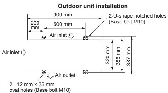
2. OUTDOOR UNIT INSTALLATION
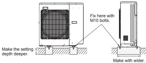
2-1. INSTALLING THE UNIT
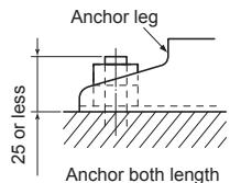
- Be sure to fix the unit's legs with bolts when installing it.
- Be sure to install the unit firmly to ensure that it does not fall by an earthquake or a gust.
Refer to the figure in the right for concrete foundation. - Do not use the drain socket and the drain caps in the cold region.
Drain may freeze and it makes the fan stop.
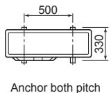
(Unit: mm)
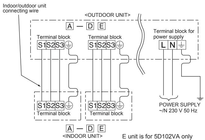
2-2. CONNECTING WIRES FOR OUTDOOR UNIT
1) Remove the service panel.
2) Loosen terminal screw, and connect indoor/outdoor unit connecting wire (B) from the indoor unit correctly on the terminal block. Be careful not to make mis-wiring. Fix the wire to the terminal block securely so that no part of its core is appeared, and no external force is conveyed to the connecting section of the terminal block.
3) Firmly tighten the terminal screws to prevent them from loosening. After tightening, pull the wires lightly to confirm that they do not move.
4) Perform 2) and 3) for each indoor unit.
5) Connect power supply cord (A).
6) Fix indoor/outdoor unit connecting wire (B) and power supply cord (A) with the cable clamps.
7) Close the service panel securely. Make sure that 3-2. PIPE CONNECTION is completed.
- After making connections between both power supply cord (A) and indoor/outdoor unit connecting wire (B), be sure to fix both cable and wire with cable clamps.
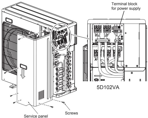
Connecting order
- Connect the terminal block in following order.
A→B→C→D→E→P
E unit is for 5D102VA only
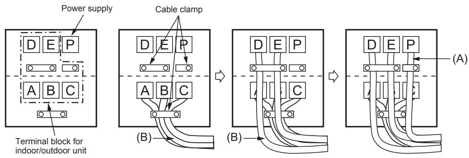
- Be sure to attach each screw to its correspondent terminal when securing the cord and/or the wire to the terminal block.
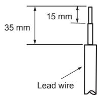
- Make earth wire a little longer than others. (More than 35mm )
- For future servicing, give extra length to the connecting wires.
3. FLARING WORK AND PIPE CONNECTION
3-1. FLARING WORK
1) Cut the copper pipe correctly with pipe cutter. (Fig. 1, 2)
2) Completely remove all burrs from the cut cross section of pipe. (Fig. 3)
- Aim the copper pipe downward while removing burrs to prevent burrs from dropping in the pipe.
3) Remove flare nuts attached to indoor and outdoor units, then put them on pipe having completed burr removal. (Not possible to put them on after flaring work.)
4) Flaring work (Fig. 4, 5). Firmly hold copper pipe in the dimension shown in the table. Select A mm from the table according to the tool selected.
5) Check
-
Compare the flared work with Fig. 6.
-
If flare is noted to be defective, cut off the flared section and do flaring work again.
| Pipe diameter (mm) | Nut (mm) | A (mm) | Tightening torque | |||
| Clutch type tool for R410A | Clutch type tool for R22 | Wing nut type tool for R22 | N·m | kgf·cm | ||
| ø6.35 (1/4") | 17 | 0 to 0.5 | 1.0 to 1.5 | 1.5 to 2.0 | 13.7 to 17.7 | 140 to 180 |
| ø9.52 (3/8") | 22 | 34.3 to 41.2 | 350 to 420 | |||
| ø12.7 (1/2") | 26 | 2.0 to 2.5 | 49.0 to 56.4 | 500 to 575 | ||
| ø15.88 (5/8") | 29 | 73.5 to 78.4 | 750 to 800 | |||
3-2. PIPE CONNECTION
1) Apply a thin coat of refrigeration oil (G) to the flared ends of the pipes and the pipe connections of the outdoor unit. Do not apply refrigeration oil on screw threads. Excessive tightening torque will result in damage on the screw.
2) Align the center of the pipe with that of the pipe connections of the outdoor unit, then hand tighten the flare nut 3 to 4 turns.
3) Tighten the flare nut with a torque wrench as specified in the table.
- Over-tightening may cause damage to the flare nut, resulting in refrigerant leakage.
- Be sure to wrap insulation around the piping. Direct contact with the bare piping may result in burns or frostbite.
3-3. INSULATION AND TAPING
1) Cover piping joints with pipe cover.
2) For outdoor unit side, surely insulate every piping including valves.
3) Using piping tape (E), apply taping starting from the entry of outdoor unit.
- Stop the end of piping tape (E) with tape (with adhesive agent attached).
- When piping have to be arranged through above ceiling, closet or where the temperature and humidity are high, wind additional commercially sold insulation to prevent condensation.
| Copper pipe Fig. 1 | Good 90° Tilted Uneven Burred Fig. 2 |
| Burr Copper pipe Spare reamer Pipe cutter Fig. 3 | Flaring tool Clutch type Wing nut type Fig. 4 |
| Die Copper pipe Flare nut Fig. 5 | Smooth all around Inside is shining without any scratches. Even length all around Fig. 6 |
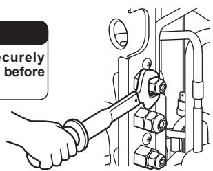
WARNING
When installing the unit, securely connect the refrigerant pipes before starting the compressor.
CAUTION
When there are the ports which are not used, make sure their nuts are tightened securely.
4. PURGING PROCEDURES, LEAK TEST, AND TEST RUN
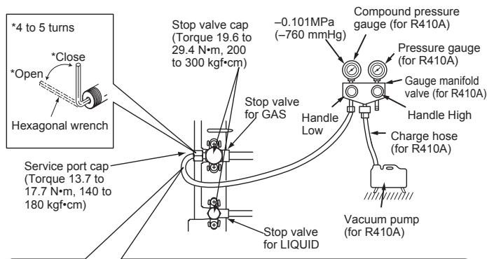
4-1. PURGING PROCEDURES AND LEAK TEST
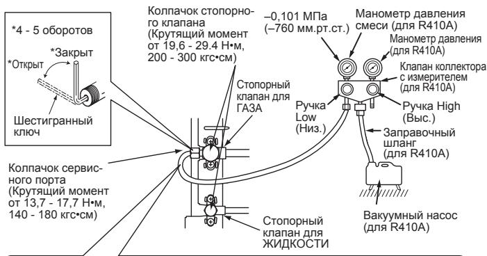
1) Remove service port cap of stop valve on the side of the outdoor unit gas pipe. (The stop valves are fully closed and covered in caps in their initial state.)
2) Connect gauge manifold valve and vacuum pump to service port of stop valve on the gas pipe side of the outdoor unit.
3) Run the vacuum pump. (Vacuumize for more than 15 minutes.)
4) Check the vacuum with gauge manifold valve, then close gauge manifold valve, and stop the vacuum pump.
5) Leave as it is for one or two minutes. Make sure the pointer of gauge manifold valve remains in the same position. Confirm that pressure gauge shows -0.101 MPa [Gauge] (-760 mmHg).
6) Remove gauge manifold valve quickly from service port of stop valve.
7) Fully open all stop valves on the gas pipe and the liquid pipe. Operating without fully opening lowers the performance and this causes trouble.
8) Refer to 1-2., and charge the prescribed amount of refrigerant if needed. Be sure to charge slowly with liquid refrigerant. Otherwise, composition of the refrigerant in the system may be changed and affect performance of the air conditioner.
9) Tighten cap of service port to obtain the initial status.
10)Leak test
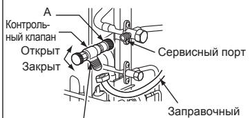
Precautions when using the control valve

When attaching the control valve to the service port, valve core may deform or loosen if excess pressure is applied. This may cause gas leak.
When attaching the control valve to the service port, make sure that the valve core is in closed position, and then tighten part A. Do not tighten part A or turn the body when valve core is in open position.
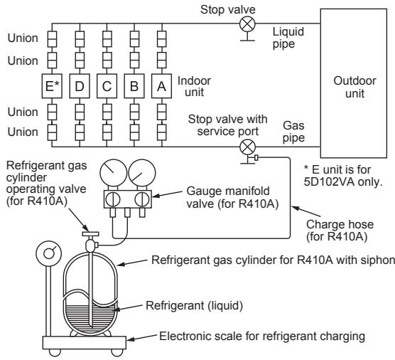
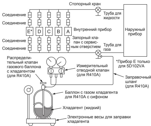
4-2. GAS CHARGE
Perform gas charge to unit.
1) Connect gas cylinder to the service port of stop valve.
2) Perform air purge of the pipe (or hose) coming from refrigerant gas cylinder.
3) Replenish specified amount of the refrigerant, while operating the air conditioner for cooling.
Note:
In case of adding refrigerant, comply with the quantity specified for the refrigerating cycle.
CAUTION:
When charging the refrigerant system with additional refrigerant, be sure to use liquid refrigerant. Adding gas refrigerant may change the composition of the refrigerant in the system and affect normal operation of the air conditioner. Also, charge the liquid refrigerant slowly, otherwise the compressor will be locked.
To maintain the high pressure of the gas cylinder, warm the gas cylinder with warm water (under 40^ ) during cold season. But never use naked fire or steam.
4-3. LOCKING THE OPERATION MODE OF THE AIR CONDITIONER (COOL, DRY, HEAT)
Description of the function:
With this function, once the operation mode is locked to either COOL/DRY mode or HEAT mode, the air conditioner operates in that mode only.
* Changing the setting is required to activate this function. Please explain about this function to your customers and ask them whether they want to use it.
[How to lock the operation mode]
1) Be sure to turn off the main power for the air conditioner before making the setting.
2) Set the "1" of SW1 on the outdoor controller board to ON to enable this function.
3) To lock the operation mode in COOL/DRY mode, set the "2" of SW1 on the outdoor controller board to OFF. To lock the operation in HEAT mode, set the same switch to ON.
4) Turn on the main power for the air conditioner.
![MITSUBISHI ELECTRIC MXZ-4D83VA MXZ-5D102VA - [How to lock the operation mode] - 1](/content/2025/01/331400/images/500df4865613e59af31f88c52e240d1335f05d872d528265dbeb8adeacf8351d.jpg)
4-4. LOWERING THE OPERATION NOISE OF THE OUTDOOR UNIT
Description of the function:
With this function, the operating noise of the outdoor unit can be lowered by reducing the operation load, for example, during nighttime in COOL mode. However, please note that the cooling and heating capacity may lower if this function is activated.
* Changing the setting is required to activate this function. Please explain about this function to your customers and ask them whether they want to use it.
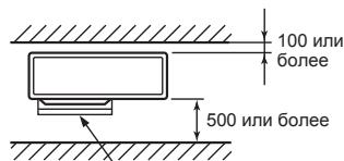
[How to lower the operating noise]
1) Be sure to turn off the main power for the air conditioner before making the setting.
2) Set the "3" of SW1 on the outdoor controller board to ON to enable this function.
3) Turn on the main power for the air conditioner.
4-5. CHANGING THE AMPERE LIMIT
Description of the function:
With this function, the amount of current that flows in the outdoor unit can be changed.
Note:
Use this function only when the amount of current exceeds the allowed value.
[How to change the ampere limit]
1) Be sure to turn off the main power for the air conditioner before making the setting.
2) Make the setting referring to the table below.
3) Turn on the main power for the air conditioner.
![MITSUBISHI ELECTRIC MXZ-4D83VA MXZ-5D102VA - [How to change the ampere limit] - 1](/content/2025/01/331400/images/a58573ffdd9f0676a85330b2f7f79c74a75c9caa9d26d2117ac6fa9cdc7f688c.jpg)
Lower the operating noise
| SW2 | MXZ-5D102VA | MXZ-4D83VA |
| ON 1 2 3 4 5 6 | 10.5 A | 10.5 A |
| ON 1 2 3 4 5 6 | 15.5 A | 15.5 A |
| ON 1 2 3 4 5 6 | Factory setting Full | Factory setting Full |
4-6. TEST RUN
- Test runs of the indoor units should be performed individually. See the installation manual coming with the indoor unit, and make sure all the units operate properly.
- If the test run with all the units is performed at once, possible erroneous connections of the refrigerant pipes and the indoor/outdoor unit connecting wires cannot be detected. Thus, be sure to perform the test run one by one.
About the restart protective mechanism
Once the compressor stops, the restart preventive device operates so the compressor will not operate for 3 minutes to protect the air conditioner.
Wiring/piping correction function
This unit has a wiring/piping correction function which corrects wiring and piping combination. When there is possibility of incorrect wiring and piping combination, and confirming the combination is difficult, use this function to detect and correct the combination by following the procedures below.
Make sure that the following is done.
Power is supplied to the unit.
- Stop valves are open.
Note:
During detection, the operation of the indoor unit is controlled by the outdoor unit. During detection, the indoor unit automatically stops operation. This is not a malfunction.
Procedure
Press the piping/wiring correction switch (SW871) 1 minute or more after turning on the power supply.
- Correction completes in 10 to 15 minutes. When the correction is completed, its result is shown by LED indication. Details are described in the following table.
- To cancel this function during its operation, press the piping/wiring correction switch (SW871) again.
- When the correction completed without error, do not press the piping/wiring correction switch (SW871) again.
When the result was "cannot be corrected", press the piping/wiring correction switch (SW871) again to cancel this function. Then, confirm the wiring and piping combination in a conventional manner by operating the indoor units one by one.
- The operation is done while the power is supplied. Make sure not to contact parts other than the switch, including the P.C. board. This may cause electric shock or burn by hot parts and live parts around the switch. Contacting the live parts may cause P.C. board damage.
- To prevent electronic control P.C. board damage, make sure to perform static elimination before operating this function.
This function does not operate when the outside temperature is 0^ or below.
LED indication during detection:
| LED1 (Red) | LED2 (Yellow) | LED3 (Green) |
| Lighted | Lighted | Once |
Result of piping/wiring correction function
| LED1 (Red) | LED2 (Yellow) | LED3 (Green) | Result |
| Lighted | Not lighted | Lighted | Completed (Problem corrected or normal) |
| Once | Once | Once | Not completed (Detection failed) |
| Other indications | Refer to “SAFETY PRE-CAUTIONS WHEN LED FLASHES” located behind the service panel. | ||
4-7. EXPLANATION TO THE USER
- Using the OPERATING INSTRUCTIONS, explain to the user how to use the air conditioner (how to use the remote controller, how to remove the air filters, how to remove or put the remote controller in the remote controller holder, how to clean, precautions for operation, etc.).
- Recommend the user to read the OPERATING INSTRUCTIONS carefully.
5. RELOCATION AND MAINTENANCE
5-1. PUMPING DOWN
When relocating or disposing of the air conditioner, pump down the system following the procedure below so that no refrigerant is released into the atmosphere.
1) Connect the gauge manifold valve to the service port of the stop valve on the gas pipe side of the outdoor unit.
2) Fully close the stop valve on the liquid pipe side of the outdoor unit.
3) Close the stop valve on the gas pipe side of the outdoor unit almost completely so that it can be easily closed fully when the pressure gauge shows 0 MPa [Gauge] (0 kgf/cm²).
4) Start the emergency COOL operation on all the indoor units.
To start the emergency operation in COOL mode, disconnect the power supply plug and/or turn off the breaker. After 15 seconds, connect the power supply plug and/or turn on the breaker, and then press the E.O. SW once. (The emergency COOL operation can be performed continuously for up to 30 minutes.)
5) Fully close the stop valve on the gas pipe side of the outdoor unit when the pressure gauge shows 0.05 to 0MPa [Gauge] (approx. 0.5 to 0kgf/cm^2 ).
6) Stop the emergency COOL operation.
Press the E.O. SW several times until all LED lamps turn off. Refer to operating instructions for details .
WARNING
When pumping down the refrigerant, stop the compressor before disconnecting the refrigerant pipes. The compressor may burst if air etc. get into it.
DEUTSCH
INHALT
(Eenheid: mm (inch))
| Openingsgroote van de buitenunit | Optionele verloopstukken (openingsgroote van de buitenunit → diameter van de verbindingsleiding) | ||
| MXZ-4D83VA | MXZ-5D102VA | Vloeibaar / gas | 6,35 (1/4) → 9,52 (3/8) : PAC-493PI9,52 (3/8) → 12,7 (1/2) : MAC-A454JP9,52 (3/8) → 15,88 (5/8) : PAC-SG76RJ12,7 (1/2) → 9,52 (3/8) : MAC-A455JP12,7 (1/2) → 15,88 (5/8) : MAC-A456JP |
| UNIT A | 6,35 (1/4) / 12,7 (1/2) | ||
| UNITB - D | UNITB - E | 6,35 (1/4) / 9,52 (3/8) | Raadpleeg de installmenthandleiding van de binnenunit voor de diametervan de verbindingsleiding van de binnenunit. |
1-4. BEPALEN VAN DE INSTALLATIEPLAATS
Hoothe van obstakel is 1200 of minder
SW1
Meluon you etietyou
4-5. AAAAAH OPIOY ENTAZH2 PEYMATOZ
- Iepiypaqn n ts λeitoupyiα:
Me autyn t n aeitoupyia, mtopeite va mtaaalete tn noootn ta peuatoC TPOEi OTNv EeWTEPIKn Movada.
Σημειών:
XpnoiOIOInote autn tn aeitoupyia mvo otav n tpexouoa tnootnta utepbaivei Tnv EITIPeTIOeVn Tm.
[TpOtno aAaayns tou opiou Evtaonps eupatos]
2. Forside (blaeserside) fri
[Sādan reduceres driftssto]
DELAR SOM SKA FINNAS TILL HANDS PÅ PLATSEN
![MITSUBISHI ELECTRIC MXZ-4D83VA MXZ-5D102VA - [Sādan reduceres driftssto] - 1](/content/2025/01/331400/images/8bf9db200668de247dfa9578a5b1d8675e4398d3e2c698934c982f66c405cda3.jpg)
SW1
Sanker driftsludet
4-5.ÄNDRA AMPEREGRÄNS
*6 Paɪnúc nɪrɪbɑ tpybɑ c xɪnaɪa'reHtOM dɔŋkɛn bɪt b He mɛnee 100 mm.
*7 I3OJRAUHbI MaTePnJI: JApocToKm NeHONJaCT C 3epHnCToCTbI O,045
*N OINIOJI3YIte N3OJIaHIO Yka3AHNO TOnIINbI. Ype3MePnaT OToIIHa 30JIaUN MoJET npIMBeCTN K HENPABInbIoY cTaHOBKe BHYtpeHrero pImo6pa, a HeJoCTaTOUHAR TOIINHua MOKET Bb3BaTb KaNAHMe BNAMr.
9 Ecnny hapkyckn np60b yctahabnnbaeTcB bIue BHTpyhenHero np60pa, mAcK. pa3-Hmua bIcoT cokpaauaTcE do 10 M.
10 Ecnn Dmna Tpy6bI npBbIaAeT 40 M, Heo6xOdma 3aIpaBka DOnONHtEnbHbIM XnlaqarehTom (R410A). (Ecnn Dmna Tpy6 He npBbIaAeT 40 M, ZanpaBka DOnONHtEnbHoro XnlaqareHa He Tpe6VeTc.)
Дононтеловийхладаг ent = A×(ДиMuHa TpybI (M)-40)
1-3. BbIbOP DOnOJIHnTEJIbHbIX CTbIKOB IДЯ PA3HbIX INAMETPOB
Ecn n DnAmetp coeHnHTenbHbIX tpy6 he cobnaaet C pa3Mepom OTBepCTnHa np6opaa, nCnoJb3yTe dOnONHtEnbHbIe CTbIKn Ira pa3hbx DnAmetpo cornaccho cneDyUoese Ta6nue.
BbCota npenTCTBn1200 nnn MeNbwe
HanaBraIouaIaIgIaIbIyBaIaIIaIaIaIaIaIaIaIaIaIaIaIaIaIaIaIaIaIaIaIaIaIaIaIaIaIaIaIaIaIaIaIaIaIaIaIaIaIaIaIaIaIaIaIaIaIaIaIaIaIaIaII (MAC-856SG)
4. IPOUeIyPbI IPOIyBKN, IPOBEPKA HA OTCYCTBNE YTEUeK I TECTOBiI IPOrOH
4-1. ПОUCEДУРы ПОДУВКИ ПОВЕРKA HA OTCYTCTBNE YTEUEK
1) CHHMMTe KONNaUOK cepBcHOrO nopTa Ha CTOnOpHom KLnAnaHe Co cTOpOHbI TpybI dIra3a HapyKHorO npi6oba. (B I3HaayAJIbHOM BInde 3aOpHbIe KLnAHaHbI NOINHOCTbIO 3aKpblI bI pNkPbITbI KOJNaUKaMn.)
2)Пдкнючite кланан Колпжторс сизмерителем и ВakуMHьн HaCoC K capBnCHOMY npotу стОнpopHOrO клanaHa Na cStOpoHe trpyБы дя ra3a HApyKHorO npi6OpA.
3) BkIIOUHTe BaKyyMhBn HAcOC. (PpOIoJXaIte Co3DaBaTb BaKyym B TeueHHe He MeHee 15 MmHyT.)
4)ПоберпгБауумсnomoшьклanaнаКолпектopaсзмертelen, 3aTeMЗakpoNTeKlapanahKoIJIeKToPocn3МрnteHmOCTAHOBITe BakuyyMHbHacOC.
5) OCTaBbTe CnCTeMy B TaKOM COCToRHH Ha OJHy-DbE MmHytIy. Y6eDInTecb, YTO CTpeLka Ha KJAnaHe KOJIeNTOpA C INMeprTeNEM OCTaeTCB B HEnOdBxHOM COCToRHH. Y6eDInTcB, YTO MAHOMTp NOKa3bIbAet pazpeXehne -0, 101 MIIa [MaHOM] (-760 MM.pT.ct.).
6)БуICTPO CHMNTe KJIanaH KOJIneKTopa C I3MePHTeM C cepBnCHOro nopTa CTOnOPHOrO KJIanaHa.
7)ПОИСТьЮ OTKpoIte BCE 3aIopNbIe KIanaHbI Ty6bl IЯ Ra3a Ipy6bl IяnxKoCTn. Ппг 3KcNlnyatauIM npH6Opa C He ПОИСТьЮ OTKpbITbIM KIanaHam ChNkaeTc erO 3ФФeKtNBHOCTb, YTO pINBODHTK HEMCnpabHOCTm.
8) CM. n. 1-2. n 3a npabBe Tne ppeDnncanHoe KOJIueCTBO XnaIaReHtA, cNII neOxOIOIMO. PnP naPobTe C xNkIMm XnaIaReHToM O6raTeBHO oCUpceTBnIeTbe 3a npabKy MeJdNeHoo. B npOTnbHom Cnyae CoCTAB XnaIaReHtBA CnCTeMe MoKet NImMeHITcb, YTO OTpNIaTeBHO NOBINHeT Hn PPOIN3BOIDNTbHOCtB KOHNIOHOpe.
9) 3aTЯнITE KoIIpaHcK cepBucHOrO nopTa dIЯ BO3BpTa K IcxOxDHomy COCTOHyHO.
10)ПюверкаHaOTCyTCTBnE yTeueK
MepbI pIeIOCTOpOxHocTn npI nCnoIb-30BaHIM KOHTPONbHOro KJanaHa
Kopnyc
ECNINPKNPEENHENKHOITPOBNB-HOTOKNAHANA K CEPBNCCHOMY NOPTYPNINAATb Ype3MEMHPOE DAJIENHEC,CEPDAHNNK KNAHANAOJETDEFOPMROBACTcN IINI OKTYPNTBC3T,3TO MOKET PNDIECBTCN K YTEKeRa3a.
Пи Кренин KMOTPOЛьНОКлANAна К сЕВМСΗОΝΥТУБДNTСБ,ЧТ绝缘н.KлANAна_HaxOДNTСВЗАКРБТOM NOLOЖENH,ЗATEM ЗагнITE чыСА.Ин He zatrayaNBaTEЧAБСИНDE NOBOPAHWBAITE KOPNYC,ecnI cepdchNK KлANAнa HaxOДNTCSB O TOKPbTOM NOLOXENH.
4-2.3AIIPABKA ΓA3A
3anpaBbTe raB 6nok.
1)ПодсоeДинHTe ra3OBb 6aJIIOH K cepBnCHOMy npOTy CTOnOpHOrO kpaHa.
2) BbInOnHInTe npOyBky Bo3Dyxa n3 Tpy6bl (nnn nnHaHa), nCxOJaIeTo OT ra3o-BORo 6aIINoHa C xnaDarEHTOM.
3)ДобавытейуkaЗанhoeКоичесвохладагета,призTomКондиционердолжен pa6oТаьВ ржиме oxlaЖдени.
Приимechanical:
Пи добavenи xna daheNTa, co6nIOaTe Tpeobanra K erO KOINueCTbY, yka-3aHbIe ДЯ ZUKla Xna daheNTa.
OCTOPOXHO:
Ipi haonHeHHn CNTeMbI OxJaeHn DOnONHITbHbIM OxJaHTeEM yOcToBepbTecb, YTO NCNoNb3yetyra KJdkn OxJaHTeB. Do6abNeHne Bo3dyuHoro OXaJIaTeN MoKET N3MeHnB CoCTab OXJaHTeN B CNTeME NOBnTb Ha HOpMaIbHyIO pAOBy TO B03duHoro KOHNIOHepa. Kpome TOrO, peKoMeHdyETc3 3aPnABnTb CNTeMy XJdKm XJaAReHToM MedJeHHO, BO N36ExaHne 3actOnopuBaHHN KOMnPecCoppa.
Для подржкь blycokoro dabneуь в ra3obom baxnohe B xonodhoe bpema rda HarpeTe ra3obij baxnoH tennoBoe (c temnepaTyOH nke 40^) 3anpeuaTcNcnpb3oBaTb OTKpbTbOrOroHb nn nap.
4-3. BLOKINPOBKA PEXIMA PAEBtI KOHdNtioHEPA (OXJAAKeHHe, CUYKA, OBOrPEB)
Onncahne dyHKcun:
C 3toiФyHKnue,ecPi paOoCHy peKIM 3a6bOkropBaH nIb6 B peKIme COOL/DRY (OXJIAXJDEHIE/CUJKA),nIb6BpeKIme HEAT (OBOTPEB), KOHNIOHep paOoTaET TOIbKO B 30m peKIme.
*IaKTHBaUHn DAnHOn FyHKUm TpeBeyTcN 3MeHeHne HactPoeK.ObbCHTe Ha3NaueHne DaHHo FyHKUm KInEHTY, IN CnpOCTe, XOHET JIN OH NC-ONJb30BaTb ee.
[BloKIpOBka pexima pa60Tb]
1) Pered BbIOnHeHnem HAcTpoKn 06a3aTeJIbHO OTKJIIOHTe 3JIeKTPOINTaHne KOHNIZMOHepa.
2) UctahOBInTe nepeKJIIOUcATEJB "1" B SW1 Ha hapyKHOI naHEnI ynpaBnEHHaNoJoxHeN ON (BKII.), YTO6bI BKJIIOuHTb 3Tu fynKUnIO.
3) UctahOBnTE nepeKIOHuaTeJIb ^ 2 " B SW1 Ha hapyXho nAHenn ynpaBHeNBA NOJIOxHeNE OFF (BbIKL.). 706bI 3a6NoKIOpaBOt peXHM pa60tBu COOL/DRY (OXAJIeEHNE/CUJKA). UTObI 3a6NoKIOpaBOt peXHM pa60tBu HEAT (OBOITPEB), yCTAHOBnTE TOT XE nepeKIOHuaTeJIb B no3uIN ON (BKJI).
4) BkIIOUHTe 3JIeKTPoINrTaHne KOHNiOHepa.
![MITSUBISHI ELECTRIC MXZ-4D83VA MXZ-5D102VA - [BloKIpOBka pexima pa60Tb] - 1](/content/2025/01/331400/images/0ae3846f2f625f9d523f5d27042e987cc3eaacf00e29c2632110449f962bb93d.jpg)
4-4. CHIXEHNPE PABOUETO WYMA HAPYXHORIO IPIPNEOPA
- Onicahne yHKlunn:
C daHno yHKnne paoohn yum hapKHO np6oopa moet 6bIb CHNKeH nyTEM yEmhIeHna paOoHeH harpy3Kn, HapIMep, B HOHoe BpeMaB peXIME COOL (OXIAKDEHNE). Tem He Mehee, obaPntE BHMaHne, YTO npu akTbauin daHHo yHKUm MOKeT cH3NTbcr OXIAkDaIoUa n HarpeBaIOUaou MoUHOCTb.
*Для akтуци данног Функци Трсуетс Измehнeне HabtpoeK.Оьяснite Ha3haueHne Данног Функци КлпeHTy,И СпocиTe,хочт Ли OH ИСпЛьЗВaTb ee.
[Chixehne pa6ooyo yyma]
1)Пелед Вьлпоннем Настpoи Кобяstelьно OTКлочи Te 3лжктупане кондциюна.
<|im_start|>assistant
2) Пелед Вьлпоннем Настpoи Кобяstelьно OTКлочи Te 3лжктупане
Кондциюна.
Надул.
Советский:
Валы:
М�務:
Тaxes:
2)UcTaHOBInTe nepeKJIIOuHTaTeNb 3" B SW1 Ha hapyKHOI naHeI ynpBaJIeHnB nOLOXKeHne ON (BKl.), tOTo6bl BKIOuHTb 3Tu fYHKLIIO.
3) BkIIOUHTe 3NeKTpOINTaHne KOHNIOHepa.
![MITSUBISHI ELECTRIC MXZ-4D83VA MXZ-5D102VA - [Chixehne pa6ooyo yyma] - 1](/content/2025/01/331400/images/f7707f29fee242c615aa24f469c14d707b8cbe0bbc3c140a7d51985e08b20aa5.jpg)
![MITSUBISHI ELECTRIC MXZ-4D83VA MXZ-5D102VA - [Chixehne pa6ooyo yyma] - 2](/content/2025/01/331400/images/f7f617a82b262b30bb66ad72236d4186a5a449ce994f3e1d37920778ca7b9406.jpg)
ChinkeHne pa6oHero 乌yma
4-5.ИЗMEHEHNE ПЕДЕЛСИЛТOKA
- OncaHne cyHKUIN:
C nOMOuHo DaHHoI yHKUIN BO3MOXHO N3MeHeHne TOKa B HApYKHom npi-6ope.
Примочин:
IcnoJIb3yIte DaHHyo fynKUIO TOIbKO, ecNI TOK npeBbIaet DOnyCTMoe 3Ha-ueHne.
[ɪnʌmɛneHHeɪpèdela cnJIbɪ TOKa]
1) 063aTeJbHO BbIKIIOUHTe PNTaHHe KOHNIOHepa OT cETn Npeed HauJIOM NaCTpoIKN.
2) BbnoJIHnTe HacpoKy corJaIcHo TaJIne HIXe.
3) BknoHTe nTahne KOHnOHepa ot cetn.
2006/95/EC: Low Voltage Directive
2006/42/EC: Machinery Directive
2004/108/EC: Electromagnetic Compatibility Directive
2009/125/EC: Energy-related Products Directive
Our authorized representative in EU, who is authorized to compile the technical file, is as follows. Unser autorisierter Vertreter in der EU, der ernachtigt ist die technischen Daten zu kompilieren, ist wie folgt. Notre représentant agreée dans L'UE, qui est autorisé à compilerer le fichier technique, est le suvant. Onze geautoriserde vertegenwoordiger in de EU, die gemachtig is het technische bestand te compilieren, is als volgt. Nuestro représentante autorizzato en la UE, que esta autorizzato para compiling er archivo技术和e, es el sigificant. Il twenty rivenditore autorizzato nelle'UE, responsabile della stesura della schedea技术ica, è il segunte. O égouiaoBtoTnevoocavTPOooTocmaCToVEE, o omoloq eivai éouiooOtoNevoc va ouvtadEi tv Texivko paKaEIo, eivai o EEnc.
MITSUBISHI ELECTRIC EUROPE, B.V.
HARMAN HOUSE, 1 GEORGE STREET, UXBRIDGE, MIDDLESEX UB8 1QQ, U.K.
Yoji SAITO
Product Marketing Director
OizzatoRE.
Vores autoriserede representant i EU, som er autoriseret til udarbejdelse af den tekniske fil, er folg
ende.
VaR EG-representant som ar auktoriserad att sammanstalla den tekniska filen r foljande.
Avrupa Birligi'nde bulunan ve teknik dosayi duzenleme yetkisine sahip yetkili tsimsilcimiza
befilirimistir.
Hau ABorup3OBaHHb npedctabntelB EC, yonlHMOeHHb na coCTabHeMe TExnueckoro
faina, yka3an Hnke.
Vareisorises E-ripehent, som har autorisjon til a utaribe deene tekniske filen, er som folger.
Valtuutetu E-udestaja, joka on valtuottu laatmaan tekisen eritelem an, on mainitt alla.
Issued: JAPAN
1 November, 2012
Toshihiko ENOMOTO
Manager, Quality Assurance Division