
UP40 - 40VCS2-34.1 - Chain saw STERWINS - Free user manual and instructions
Find the device manual for free UP40 - 40VCS2-34.1 STERWINS in PDF.

| Product type | Cordless battery chainsaw |
| Brand | STERWINS |
| Model | UP40 - 40VCS2-34.1 |
| Rated voltage | 36 V DC |
| Battery type | Li-Ion 5 Ah (model 40VBA2-50.1) |
| Guide bar length | 415 mm |
| Max cut length | 340 mm |
| Chain | 355 mm, model 91PJ052X |
| Max chain speed | 15 m/s |
| Oil tank capacity | 120 ml |
| Lubrication | Automatic |
| Weight (with battery) | 5.29 kg |
| Sound pressure level | 89.1 dB(A) (K=3 dB(A)) |
| Sound power level | 100.1 dB(A) (K=3 dB(A)) |
| Vibration level | 1.946 m/s² (K=1.5 m/s²) |
| No-load speed | 7300 min⁻¹ |
| Intended use | Outdoor, pruning, felling, cutting |
| Safety | Chain brake, hand guard, safety lock |
| Warranty | 3 years |
| Maintenance | Regular cleaning, lubrication, chain sharpening |
Frequently Asked Questions - UP40 - 40VCS2-34.1 STERWINS
User questions about UP40 - 40VCS2-34.1 STERWINS
0 question about this device. Answer the ones you know or ask your own.
Ask a new question about this device
Download the instructions for your Chain saw in PDF format for free! Find your manual UP40 - 40VCS2-34.1 - STERWINS and take your electronic device back in hand. On this page are published all the documents necessary for the use of your device. UP40 - 40VCS2-34.1 by STERWINS.
USER MANUAL UP40 - 40VCS2-34.1 STERWINS
natural_image
Illustration of a chain-linking power tool (no text or symbols)
EAN :3276000660170

natural_image
Pure technical line drawing of a mechanical component with no text or symbols10.1 A NOSSA GARANTIA
2.2 SYMBOLE NA PRODUKCIE
CE
2.5 BEZPIECZEŃSTWO W MIEJSCU PRACY

10.1 NASZA GWARANCJA
natural_image
Illustration of a chain-linking power tool (no text or symbols)

EAN :3276000660170


Thank you for choosing this product. Upon designing and manufacturing our products, we place all of our efforts into ensuring an excellent quality that meets the needs of the users. Following these instructions allow to optimize the lifetime
IMPORTANT! IN ORDER TO OBTAIN THE UTMOST SATISFACTION FROM THIS PRODUCT UPON SETTING IT UP, USING IT, AND MAINTAINING IT, WE RECOMMEND THAT YOU CAREFULLY READ THIS USER MANUAL BEFORE USING THE PRODUCT. PLEASE PAY ATTENTION TO BASIC WARNINGS RELATING TO SAFETY WITHIN THIS MANUAL, AND KEEP THE MANUAL FOR LATER REFERENCE.

IMPORTANT, KEEP THE MANUAL FOR LATER REFERENCE : READ CAREFULLY
Contents
- Intended use of Battery Chain Saw 34 cm
- Safety Instructions
- Technical data
- Assembly
- Transportation
-
Wintering
-
Storage
- Maintenance
- End of life
- Warranty
- CE declaration of conformity
1. INTENDED USE OF BATTERY CHAIN SAW 34 CM
This product is intended for outdoor use only, and must not be used inside a building under any circumstances. The cordless chain saw is only intended for use in dry and well-illuminated conditions. This chain saw is only intended to be used for basic limbing, felling, woodcutting, and remove buttress roots. All of the wooden objects intended to be cut with this chain saw should be no thicker than the guide bar's maximum cutting capabilities. It must not be used for cutting other materials, such as plastic, stone, metal or wood that contains foreign objects. Do not use it for others purposes. The maximum cutting capacity must be observed. Do not cut branches exceeding the stated maximum capacity. Do not use it for others purposes. The product is not intended to be used by children or persons with reduced physical, mental or sensory capabilities.
After unwrapping the packing, make sure that the product is complete with its accessories (if any). If the product is damaged or has any defect, please do not use it and bring back it to your dealer.
If you give this tool to another people, please give him also this instruction manual.
Please note that our equipment has not been designed for use in commercial, trade or industrial applications. Our warranty will be voided if the machine is used in commercial, trade or industrial businesses or for equivalent purposes. This product has been designed to be used over a period of 6 years (Expected lifetime).
2. SAFETY INSTRUCTIONS

WARNING : Read all safety warnings and all instructions.
Failure to follow the warnings and instructions may result in electric shock, fire and/or serious injury.
Save all warnings and instructions for future reference.
2.1 GENERAL SAFETY WARNINGS
- Do not operate the chain saw near glass enclosures, automobiles, trucks, window wells, drop-offs, etc. without properly adjusting the aim of the discharge.
- Do not force or overload the product. It will perform better and safer when it is used at the rate that it was designed to work at.
- If the product is already assembled, please make sure that all screws are tightly fixed before using it. If the product requires that you assemble it, please make sure upon opening the package that all the elements needed for setting up the product have been provided. If the product is damaged or has defects, do not use it and take it back to the nearest store.
- The term "power tool" in the warnings refers to your mains-operated (corded) power tool or battery-operated (cordless) power tool.
2.2 SYMBOLS ON THE PRODUCT

Complies with European standards: This symbol means that this appliance is compliant with the applicable European directives, and a test of compliance with these directives has been performed.

Single mark of circulation of products on the market of the Member States of the Customs Union.

Ukrainian conformity marking
Electrical products should not be discarded with household products. Used electrical products must be collected separately and disposed of at collection points provided for this purpose. Talk with your local authorities or dealer for advice on recycling.

Read and understand all instructions before operating the product, follow all warning and safety instructions.

*Universal : compatible only with Sterwins UP40, Lexman UP40 and Dexter UP40 products.

Guaranteed sound power level (tested according to Directive 2000/14/EC as amended by 2005/88/EC).

Do not expose the product to rain or wet conditions.


Appropriate ear, eye, and head protection must be worn.
Do not use chain saw one handed.
Always use chain saw two-handed.
Beware of chain saw kickback and avoid contact with bar tip.
Read the instruction manual.
Wear head protection.
Wear safety glasses.
Wear a face shield.
Wear protective clothing.
2.3 SYMBOLS IN THIS MANUAL

Type and source of the danger : Failure to observe this warning may result in physical injury or death.

Type and source of the danger: This symbol indicates that damage to the appliance, the environment or other property may occur as a result of non-observance of this warning.

Note : This symbol indicates important information for better understanding of the product.

Read the manual: This symbol indicates that you need to read the user manual carefully.

Please refer to the corresponding illustration at the end of the booklet.

Remove battery during transportation, storage, repair work and cleaning.

Recycle this instruction manual

This product is recyclable. If it cannot be used anymore, please take it to waste recycling centre.

Recycle the packaging of the product.
2.4 GENERAL POWER TOOL SAFETY WARNINGS

WARNING: Read all safety warnings, instructions, illustrations and specifications provided with this power tool. Failure to follow all instructions listed below may result in electric shock, fire and/or serious injury.
SAVE ALL WARNINGS AND INSTRUCTIONS FOR FUTURE REFERENCE. The term "power tool" in the warnings refers to your mains-operated (corded) power tool or battery-operated (cordless) power tool.
2.5 WORK AREA SAFETY
- Keep work area clean and well lit. Cluttered or dark areas invite accidents.
- Do not operate power tools in explosive atmospheres, such as in the presence of flammable liquids, gases or dust. Power tools create sparks which may ignite the dust or fumes.
- Keep children and bystanders away while operating a power tool. Distractions can cause you to lose control.
2.6 ELECTRICAL SAFETY
- Power tool plugs must match the outlet. Never modify the plug in any way. Do not use any adapter plugs with earthed (grounded) power tools. Unmodified plugs and matching outlets will reduce risk of electric shock.
- Avoid body contact with earthed or grounded surfaces, such as pipes, radiators, ranges and refrigerators. There is an increased risk of electric shock if your body is earthed or grounded.
-
Do not expose power tools to rain or wet conditions. Water entering a power tool will increase the risk of electric shock.
-
Do not abuse the cord. Never use the cord for carrying, pulling or unplugging the power tool. Keep cord away from heat, oil, sharp edges or moving parts. Damaged or entangled cords increase the risk of electric shock.
- When operating a power tool outdoors, use an extension cord suitable for outdoor use. Use of a cord suitable for outdoor use reduces the risk of electric shock.
- If operating a power tool in a damp location is unavoidable, use a residual current device (RCD) protected supply. Use of an RCD reduces the risk of electric shock.
2.7 PERSONAL SAFETY
- Stay alert, watch what you are doing and use common sense when operating a power tool. Do not use a power tool while you are tired or under the influence of drugs, alcohol or medication. A moment of inattention while operating power tools may result in serious personal injury.
- Use personal protective equipment. Always wear eye protection. Protective equipment such as dust mask, non-skid safety shoes, hard hat, or hearing protection used for appropriate conditions will reduce personal injuries.
- Prevent unintentional starting. Ensure the switch is in the off-position before connecting to power source and/or battery pack, picking up or carrying the tool. Carrying power tools with your finger on the switch or energising power tools that have the switch on invites accidents.
- Remove any adjusting key or wrench before turning the power tool on. A wrench or a
• key left attached to a rotating part of the power tool may result in personal injury. - Do not overreach. Keep proper footing and balance at all times. This enables better control of the power tool in unexpected situations.
- Dress properly. Do not wear loose clothing or jewellery. Keep your hair, clothing and gloves away from moving parts. Loose clothes, jewellery or long hair can be caught in moving parts.
- If devices are provided for the connection of dust extraction and collection facilities, ensure these are connected and properly used. Use of dust collection can reduce dust-related hazards.
- Do not let familiarity gained from frequent use of tools allow you to become complacent and ignore tool safety principles. A careless action can cause severe injury within a fraction of a second.
2.8 POWER TOOL USE AND CARE
- Do not force the power tool. Use the correct power tool for your application. The correct power tool will do the job better and safer at the rate for which it was designed.
- Do not use the power tool if the switch does not turn it on and off. Any power tool that cannot be controlled with the switch is dangerous and must be repaired.
- Disconnect the plug from the power source and/or the battery pack from the power tool before making any adjustments, changing accessories, or storing power tools. Such preventive safety measures reduce the risk of starting the power tool accidentally.
- Store idle power tools out of the reach of children and do not allow persons unfamiliar with the power tool or these instructions to operate the power tool. Power tools are dangerous in the hands of untrained users.
- Maintain power tools and accessories. Check for misalignment or binding of moving parts, breakage of parts and any other condition that may affect the power tools operation. If damaged, have the power tool repaired before use. Many accidents are caused by poorly maintained power tools.
- Keep cutting tools sharp and clean. Properly maintained cutting tools with sharp cutting edges are less likely to bind and are easier to control.
- Use the power tool, accessories and tool bits etc. in accordance with these instructions, taking into account the working conditions and the work to be performed. Use of the power tool for operations different from those intended could result in a hazardous situation.
- Keep handles and grasping surfaces dry, clean and free from oil and grease. Slippery handles and grasping surfaces do not allow for safe handling and control of the tool in unexpected situations.
2.9 BATTERY TOOL USE AND CARE
- Recharge only with the charger specified by the manufacturer. A charger that is suitable for one type of battery pack may create a risk of fire when used with another battery pack.
- Use power tools only with specifically designated battery packs. Use of any other battery packs may create a risk of injury and fire.
- When battery pack is not in use, keep it away from other metal objects, like paper clips, coins, keys, nails, screws or other small metal objects, that can make a connection from one terminal to another. Shorting the battery terminals together may cause burns or a fire.
- Under abusive conditions, liquid may be ejected from the battery; avoid contact. If contact accidentally occurs, flush with water. If liquid contacts eyes, additionally seek medical help. Liquid ejected from the battery may cause irritation or burns.
- Do not use a battery pack or tool that is damaged or modified. Damaged or modified batteries may exhibit unpredictable behaviour resulting in fire, explosion or risk of injury.
- Do not expose a battery pack or tool to fire or excessive temperature. Exposure to fire or temperature above 130^ may cause explosion.
- Follow all charging instructions and do not charge the battery pack or tool outside the temperature range specified in the instructions. Charging improperly or at temperatures outside the specified range may damage the battery and increase the risk of fire.
2.10 SERVICE
- Have your power tool serviced by a qualified repair person using only identical replacement parts. This will ensure that the safety of the power tool is maintained.
- Never service damaged battery packs. Service of battery packs should only be performed by the manufacturer or authorized service providers.
2.11 CHAIN SAW SAFETY WARNINGS:
- Keep all parts of the body away from the saw chain when the chain saw is operating. Before you start the chain saw, make sure the saw chain is not contacting anything. A moment of inattention while operating chain saws may cause entanglement of your clothing or body with the saw chain.
- Always hold the chain saw with your right hand on the rear handle and your left hand on the front handle. Holding the chain saw with a reversed hand configuration increases the risk of personal injury and should never be done.
- Hold the chain saw by insulated gripping surfaces only, because the saw chain may contact hidden wiring. Saw chains contacting a "live" wire may make exposed metal parts of the chain saw "live" and could give the operator an electric shock.
- Wear eye protection. Further protective equipment for hearing, head, hands, legs and feet is recommended. Adequate protective equipment will reduce personal injury from flying debris or accidental contact with the saw chain.
-
Do not operate a chain saw in a tree, on a ladder, from a rooftop, or any unstable support. Operation of a chain saw in this manner could result in serious personal injury.
-
Always keep proper footing and operate the chain saw only when standing on fixed, secure and level surface. Slippery or unstable surfaces may cause a loss of balance or control of the chain saw.
- When cutting a limb that is under tension, be alert for spring back. When the tension in the wood fibres is released, the spring loaded limb may strike the operator and/or throw the chain saw out of control.
- Use extreme caution when cutting brush and saplings. The slender material may catch the saw chain and be whipped toward you or pull you off balance.
- Carry the chain saw by the front handle with the chain saw switched off and away from your body. When transporting or storing the chain saw, always fit the guide bar cover. Proper handling of the chain saw will reduce the likelihood of accidental contact with the moving saw chain.
- Follow instructions for lubricating, chain tensioning and changing the bar and chain. Improperly tensioned or lubricated chain may either break or increase the chance for kickback.
- Cut wood only. Do not use chain saw for purposes not intended. For example: do not use chain saw for cutting metal, plastic, masonry or non-wood building materials. Use of the chain saw for operations different than intended could result in a hazardous situation.
- Follow all instructions when clearing jammed material, storing or servicing the chain saw. Make sure the switch is off and the battery pack is removed.
Unexpected actuation of the chain saw while clearing jammed material or servicing may result in serious personal injury.
- Do not attempt to fell a tree until you have an understanding of the risks and how to avoid them. Serious injury could occur to the operator or bystanders while felling a tree.
2.12 CAUSES AND OPERATOR PREVENTION OF KICKBACK:
- Kickback may occur when the nose or tip of the guide bar touches an object, or when the wood closes in and pinches the saw chain in the cut.
- Tip contact in some cases may cause a sudden reverse reaction, kicking the guide bar up and back towards the operator.
- Pinching the saw chain along the top of the guide bar may push the guide bar rapidly back towards the operator.
- Either of these reactions may cause you to lose control of the saw which could result in serious personal injury. Do not rely exclusively upon the safety devices built into your saw.
-
As a chain saw user, you should take several steps to keep your cutting jobs free from accident or injury.
-
Kickback is the result of chain saw misuse and/or incorrect operating procedures or conditions and can be avoided by taking proper precautions as given below:
- Maintain a firm grip, with thumbs and fingers encircling the chain saw handles, with both hands on the saw and position your body and arm to allow you to resist kickback forces. Kickback forces can be controlled by the operator, if proper precautions are taken. Do not let go of the chain saw.
- Do not overreach and do not cut above shoulder height. This helps prevent unintended tip contact and enables better control of the chain saw in unexpected situations.
- Only use replacement guide bars and saw chains specified by the manufacturer. Incorrect replacement guide bars and saw chains may cause chain breakage and/or kickback.
- Follow the manufacturer's sharpening and maintenance instructions for the saw chain. Decreasing the depth gauge height can lead to increased kickback.
2.13 RESIDUAL RISKS
- Familiarise yourself with the use of this product by means of this instruction manual. Memorise the safety directions and follow them to the letter. This will help to prevent risks and hazards. Always be alert when using this product, so that you can recognise and handle risks early. Fast intervention can prevent serious injury and damage to property. Switch off and disconnect from the battery if there are malfunctions.
-
Even if all instructions are strictly followed, there are still some factors that could lead to hazards, such as :
-
Thrown out pieces of the work piece.
-
Vibration injuries : use designated handles and try to reduce working time and exposure.
-
Injuries caused by noise: wear ear protection and reduce working time and exposure.
- Inhalation of dust and particles.
- Wear eye protection at all times.
If you experience any of these factors while using the machine, stop the machine consult your doctor immediately
- Injuries may be caused or aggravated by prolonged use of a tool. When using any tool for prolonged periods, ensure you take regular breaks.
- Prolonged use of the product exposes the user to vibrations that can cause a range of conditions collectively known as hand-arm vibration syndrome (HAVS) e.g. fingers going white; as well as specific diseases such as carpal tunnel syndrome.
-
To reduce this risk when using the product, always wear protective gloves and keep your hands warm.
-
TECHNICAL DATA
| Model | 40VCS2-34.1 |
| Rated voltage (V d.c.) | 36 V d.c. |
| Oil tank capacity | 120 ml |
| Max Chain Speed | 15m/s |
| Saw Chain | 14 inches |
| Saw Chain model | 91PJ052X |
| Guide bar model | 140SDEA041 |
| Guide bar length | 415 mm |
| Max. cutting length | 340 mm |
| Oil type | Anti-wear hydraulic oil |
| Oil control | Automatic |
| Machine weigh (including battery pack) | 5.29 kg with 40VBA2-50.1 |
| The emission values as below according to EN 62841: | |
| Measured sound pressure level (dB(A)) | 89.1 dB(A) K=3 dB(A) |
| Measured sound power level (dB(A)) | 100.1 dB(A), K=3dB(A) |
| Vibration level (K=1.5m/s2) | 1,946 m/s2 |
| No-load speed (min-1) | 7300 |
The declared vibration total value(s) and the declared noise emission value(s) have been measured in accordance with a standard test method and may be used for comparing one tool with another; the declared vibration total value(s) and the declared noise emission value(s) may also be used in a preliminary assessment of exposure. The vibration and noise emissions during actual use of the power tool can differ from the declared values depending on the ways in which the tool is used especially what kind of workpiece is processed; the emissions value need to identify safety measures to protect the operator that are based on an estimation of exposure in the actual conditions of use (taking account of all parts of the operating cycle such as the times when the tool is switched off and when it is running idle in addition to the trigger time).
Recommendation for the operator to wear hearing protection.
| Battery pack | |
| Type of battery | Li-lon |
| Model | 40VBA2-50.140VBA2-50.1XXX |
| Rated voltage [V d.c.] | 36V d.c. |
| Battery rated capacity | 5Ah Li-lon |
| Number of battery cells | 20 |
| Weight [kg] | 1.29 kg |
| Charger pack | ||
| Model | 40VCH1-3A.140VCH1-3A.1XXX | 40VCH2-6A.140VCH2-6A.1XXX |
| Rated input | 100-240V~ | 220-240V~ |
| Rated output | 42V d.c. | 42V d.c. |
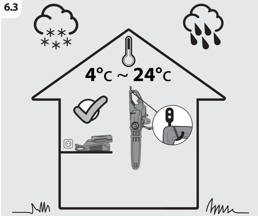
| Working temperature [°C] | 4°C~24°C | 4°C~24°C |
| Weight [kg] | 0.605 kg | 1.06 kg |
4. ASSEMBLY

WARNING! The product must be fully assembled before operation! Do not use a product that is only partly assembled or assembled with damaged parts! Follow the assembly instructions step-by-step and use the pictures provided as a visual guide to easily assemble the product!
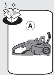
4.1 UNBOXING
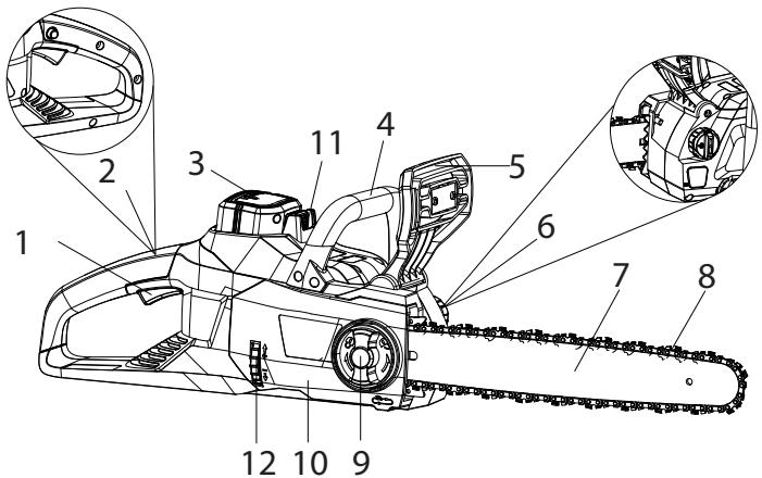

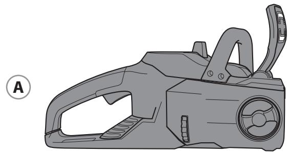
1.ON/OFF trigger switch
2. Safety lock-off button
3.Battery (not included)
4.Front handle
5.Hand guard/chain brake
6.Oil cap
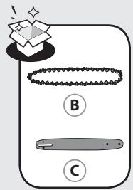
7. Guide bar
8.Chain
9. Locking knob
10.Side cover
11.Battery unlock button
12. Chain tension wheel
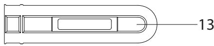
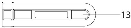
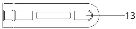
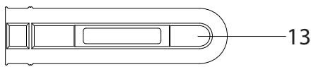
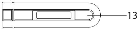
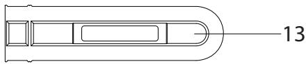
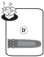
13.Blade sheath
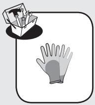
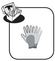
- Wear gloves when unboxing.
- Do not use cutter, knife, saw or any other similar tool for unboxing.
- Carry the tool only by the handle pls check.
- Keep the box for further reuse (transport and storage).
- Keep instruction manual in a dry area for further consultation.
4.2 INSTALLATION
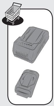
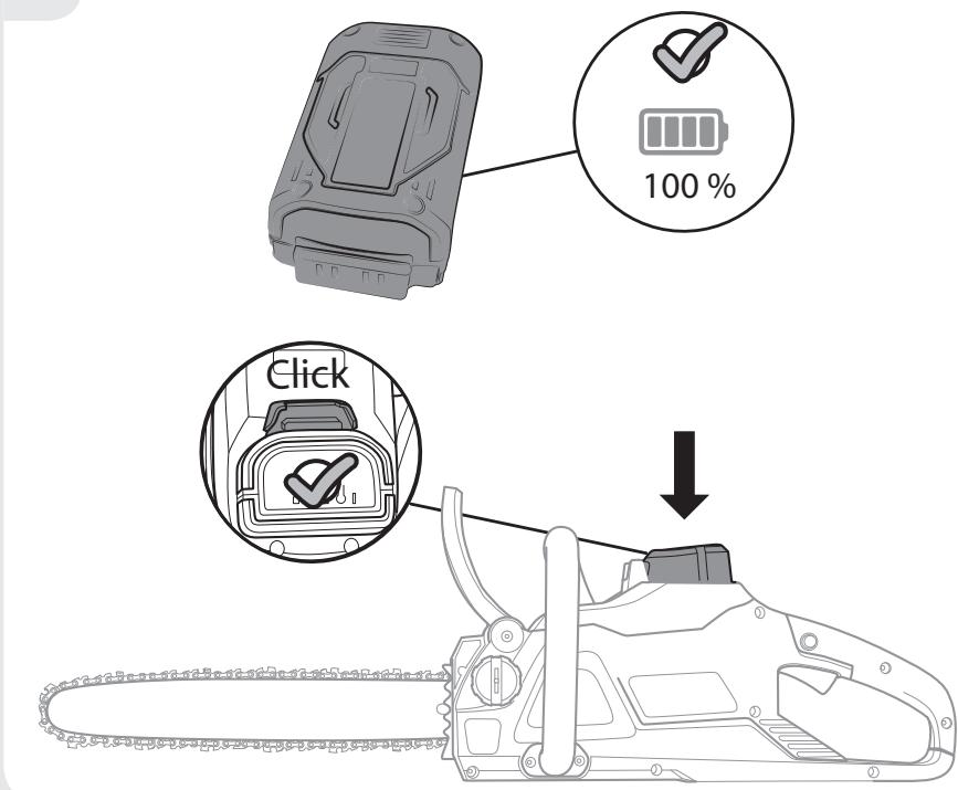
Installing/Removing the battery pack : illustration 3.4
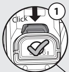
WARNING : Make sure the latch on the bottom of the battery pack snaps in place and the battery pack is fully seated and secure in the product's battery docking port before beginning operation.
Failure to securely seat the battery pack could cause the battery pack to fall out, resulting in serious personal injury.
To install : To attach, align and slide the battery pack onto the slots of the battery docking port until it locks in place.
To remove : To release, press the battery unlock button and remove the battery pack from the product.
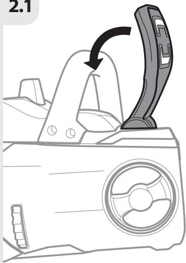
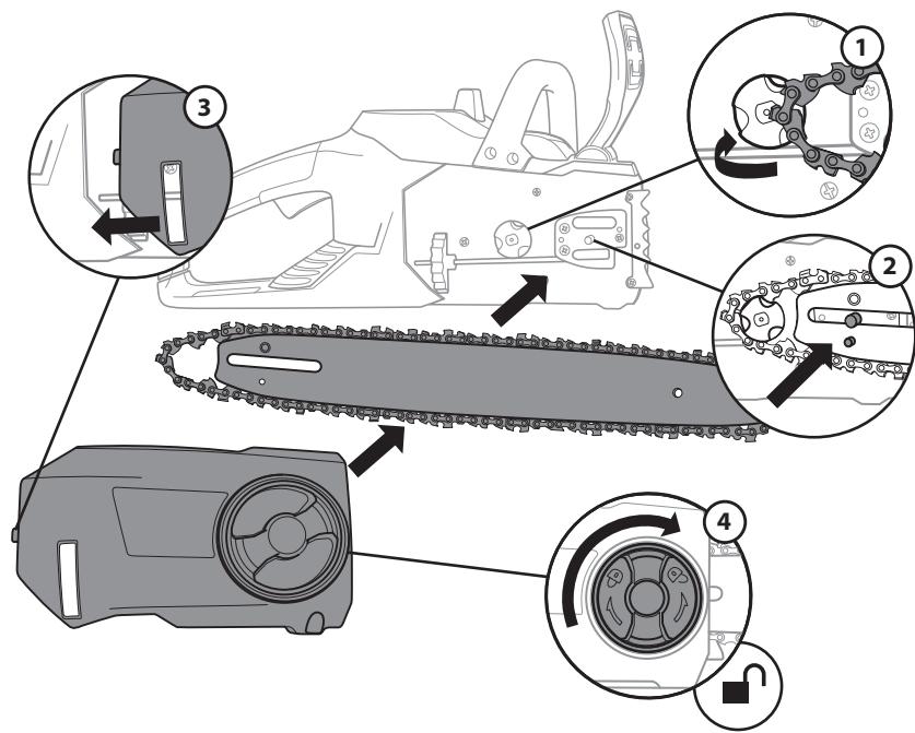
Assemble the guide bar and the saw chain : illustration 2.1 to 2.5
- Place the saw body on a firm and level surface.
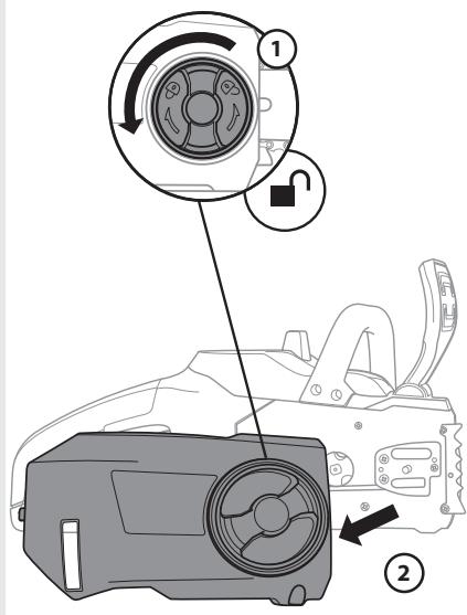
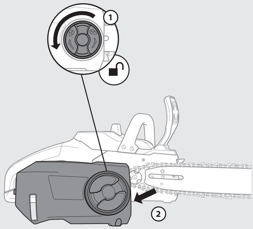
- Rotate the locking knob anticlockwise to remove the cover from the saw's body.
- With the help of protective gloves, wrap the saw chain around the guide bar, making sure that the teeth are aimed in the direction of rotation. The chain should be properly set in the slot running along the entire outside edge of the guide bar.
- Place the saw chain around the sprocket while lining up the slot in the guide bar with the internal bolt at the base of the saw and the chain tensioning pin in the guide bar's pin hole. The chain tensioning pin may need adjustment to properly align with the hole in the guide bar. Use the chain tensioning wheel to adjust its location until it fits in the guide bar.
- Turn the chain tensioning wheel to preliminarily tighten the guide bar enough that it stays in place. While holding the bar still, place the cover back onto the saw. Make sure the tab properly lines up with the slot on the body of the saw. Lock the cover in place with the cover locking knob by turning it clockwise until it engages.
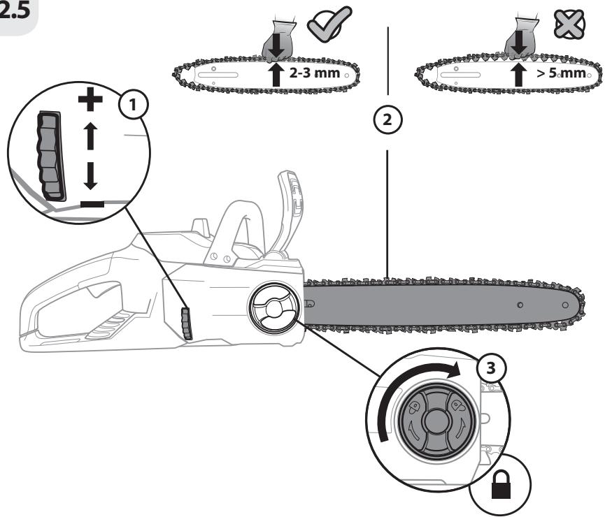
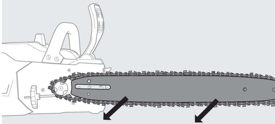
Tensioning the chain : illustration 2.5
- Check the chain tension by pulling the saw chain away from the guide bar. A properly tensioned chain should have roughly 3 mm of distance between itself and the bar guide.
- If adjustments are needed, loosen the bar adjustment locking knob one full turn.
- To adjust the saw chain tension, rotate the chain tensioning wheel. Rotating the wheel upwards increases the tension while rotating it downwards decreases tension. A properly tensioned chain should have no sag and should only be able to be pulled 3 mm away from the guide bar of the saw.
- Once the chain is properly tensioned, tighten the locking knob. Do not over-tension the chain: this will lead to excessive wear and reduces the life of both the bar and chain.

Note: The saw chain must be tensioned properly in order to ensure safe operation.
The chain tension is optimal if the saw chain can be lifted 3 mm from the centre of the guide bar. Since the saw chain heats up during operation, its length can therefore fluctuate. Check the chain tension every 10 minutes of operation and adjust as necessary, particularly for new saw chains. Slacken the saw chain after the work is completed since it shortens when cooling down. In doing so, you can elongate the chain's life and prevent damage.
4.3 PREPARATION
Before each use, check the following items to ensure safe working conditions.
Chain saw :
Before beginning work, inspect the chain saw for damage to the housing, the saw chain and the guide bar. Never use an obviously damaged machine.
Chain oil :
Check the fill level of the oil tank. Also check whether there is sufficient oil available while working. Never operate the saw if there is no oil or the oil level has dropped below the minimum oil level mark, in order to prevent damage to the chain saw. On average, an oil filling is sufficient for approximately 10 minutes of cutting operation (depending on the duration of pauses and the density of the work piece).
Saw chain :
Check the tension of the saw and the condition of the saw. The sharper the saw chain is, the easier and more manageable operations will be. The same applies to chain tension. Check the tension every 10 minutes of operation to maximise safety. New saw chains in particular are subject to changes due to the heat created by operation.
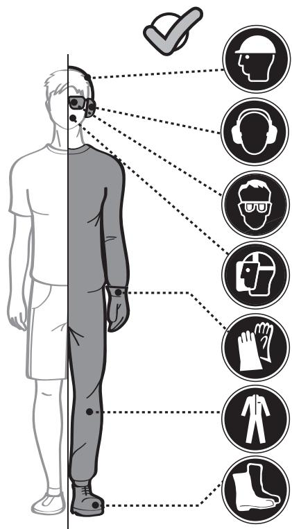
Safety equipment and protective clothing :
Make absolutely sure to wear the appropriate close-fitting protective clothing such as protective pants, gloves and safety shoes. Wear a safety helmet with integrated hearing protection and a face guard to provide protection against falling and recoiling branches.
Do secure long hair so that it is above shoulder level.
Use the following safety clothing and protective equipment when operating the product:
- Helmet with visor and neck guard
- Hearing protectors
- Breathing mask
- Gloves with approved saw protection
- Protective leggings with approved saw protection
- Steel toe cap boots with approved saw protection
- First aid kit in case of injury.
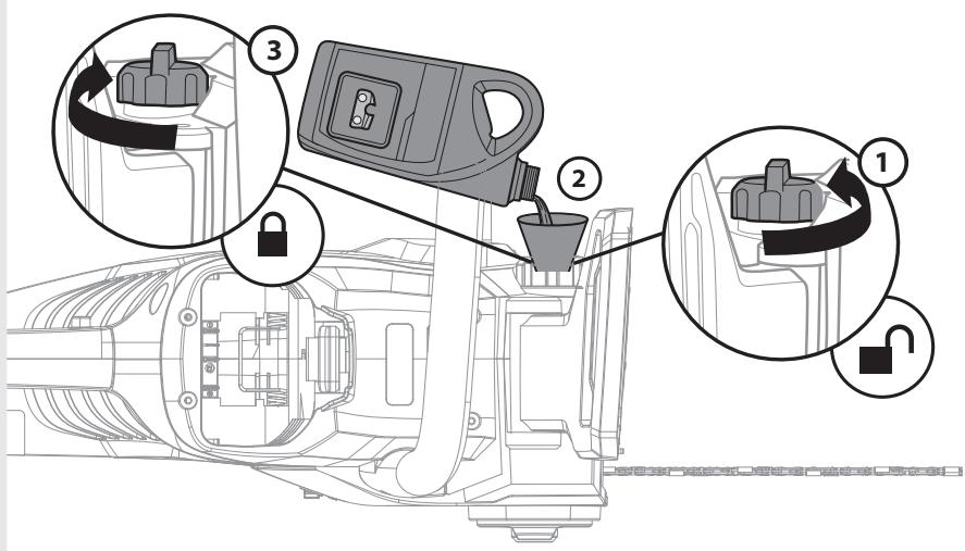
Filling the auto oil system : illustration 3.3
CAUTION ! The chain saw is NOT supplied filled with oil. It is essential to fill with oil before use. Never operate the chain saw without chain oil or at an empty oil tank level, as this will result in extensive damage to the product. Chain life and cutting capacity depends on optimum lubrication. Therefore, the chain is automatically oiled during operation via the oil outlet.
This chain saw features an auto-oiling system to keep the chain and guide bar properly lubricated. The oil level indicator shows the remaining oil in the chainsaw.
If the oil level decreases to below one quarter capacity, refill it with the proper bar and chain oil. To fill the oil reservoir:
- Remove the oil cap. Fill the reservoir with bar and chain oil until the oil level has reached full capacity.
- Put the oil cap back on. Make sure to check the oil level after every 10 minutes of use. Unplug the chain saw before checking oil levels or filling the oil reservoir.

CAUTION ! To prevent oil leakage, ensure machine is left in a horizontal position (oil filler cap upright) when not in use. Use only the recommended oil to avoid damage to the chain saw. Never use recycled/old oil.
4.4 FIRST USE
Check the battery

WARNING! Read the « SAFETY INSTRUCTION » section at the beginning of this manual including all text under subheading therein before using this product.

The battery is not fully charged at the time of purchase. Before using the product for the first time, place the battery in the charger and charge it fully.
Pay particular attention using the machine for the first time : focus and dedicate all your attention to this first use. Make the first trial on a free space with no obstacle and no surrounding element
4.5 OPERATION
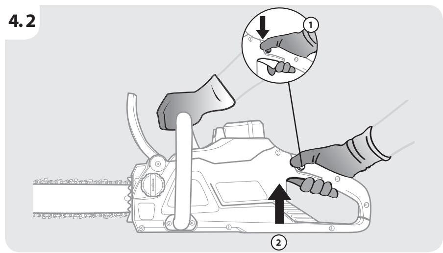
Switching on/off : illustration 4.2
To turn the tool ON, push and hold the safety lock-off button with your thumb, while squeezing the ON/OFF trigger switch. Once the trigger switch engages, you can release the safety lock-off button and proceed with operation. The safety lock-off button reduces the risk of accidental starting. To turn the tool OFF, release the ON/OFF trigger switch.

WARNING : Do not insert or remove the battery pack while the trigger is pressed or while the chain saw is in motion.
Operation safety warnings

CAUTION! Always wear safety glasses. Wear a filter mask if the operation is dusty. Use of proper gloves and substantial footwear is also recommended.
- Check the product, its battery pack and charger as well as accessories for damage before each use. Do not use the product if it is damaged or shows wear.
- Double check that the accessories and attachments are properly fixed.
• Always hold the product on its handle. Keep the handle dry to ensure safe support. - Ensure that the air vents are always unobstructed and clear. Clean them if necessary with a soft brush. Blocked air vents may lead to overheating and damage the product.
- Switch the product off immediately if you are disturbed while working by other people entering the working area. Always let the product come to complete stop before putting it down.
-
Do not overwork yourself. Take regular breaks to ensure you can concentrate on the work and have full control over the product.
-
Before switching the product on, check whether it has been assembled correctly and all the moving parts are running smoothly.
- We recommend slightly dampening surfaces in dusty conditions or using a mister attachment.
- Operate the product only at reasonable hours – not early in the morning or late at night when people might be disturbed.
- Avoid using the product in bad weather conditions, especially when there is a risk of lightning. Do not operate the product in poor lighting. The operator requires a clear view of the work area to identify potential hazards.
- Use of hearing protection reduces the ability to hear warnings (shouts or alarms). The operator must pay extra attention to what is going on in the work area. Do not get distracted, and always concentrate on the task.
- Operating similar tools nearby increases both the risk of hearing injury and the potential for other persons to enter your work area.
- Keep firm footing and balance.
- Do not overreach. Overreaching can result in loss of balance. Always be sure of the footing on slopes.
- Walk, never run. Keep all parts of your body away from any moving part.
- Never run the product without the proper equipment attached.
- Do not modify the product in any way or use parts and accessories that are not recommended by the manufacturer.

If the product is dropped, suffers heavy impact or begins to vibrate abnormally, immediately stop the product and inspect for damage or identify the cause of the vibration. Any damage should be properly repaired or replace by an authorized service centre.
- To reduce the risk of injury associated with contacting rotating parts, always stop the machine, remove the battery pack, and make sure all moving parts have stopped:
- before cleaning or clearing a blockage
- when leaving the product unattended
- before installing or removing attachments
- before checking, maintaining or working on the product
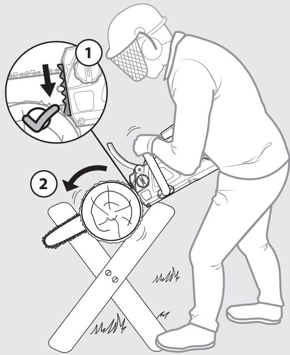
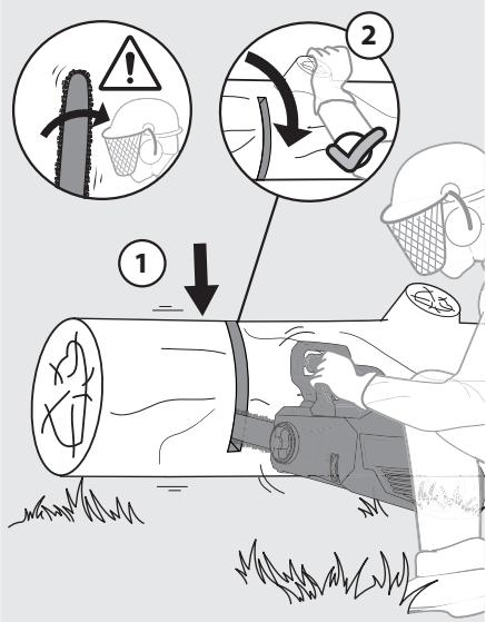
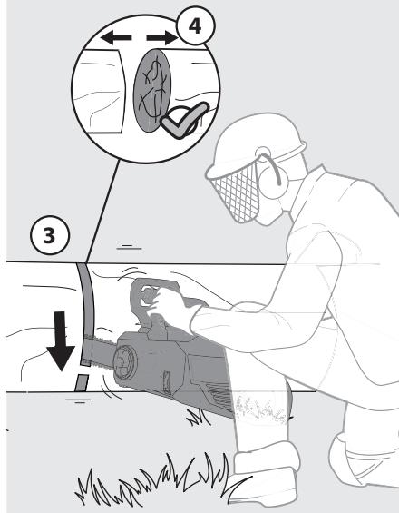
Basic operating/cutting procedure : illustration 4.1 to 4.5

WARNING: Chainsaws by their very nature are extremely dangerous machines and should be handled with respect!
We strongly recommend that before use of this product, you attend a chainsaw training course to familiarise yourself with the maintenance and usage of these products! Thoroughly read this manual and adhere to all safety instructions at all times. The manufacturer will not be held liable for any accidents/injuries caused due to misuse or incorrect maintenance of this product!
- To become proficient, attend a recognised chainsaw training course to learn how to operate chainsaws safely and effectively. Familiarise yourself with all the controls and switches. Practice all movements with the product switched off.
- Always hold the product firmly with both hands; front handle with the left hand and rear handle with the right hand. Fully grip both handles at all times during operation. Never operate the product using only one hand.
- Only use the product with a secure stance. Hold the product at the right-hand side of your body.
NOTE : Any other cutting positions should not be used with this product except the chainsaw.
- Check the lubrication.
Start the tool and check whether the chain can give off a spray of oil within a few seconds. If an oil trace can be seen, the chainsaw is lubricating.
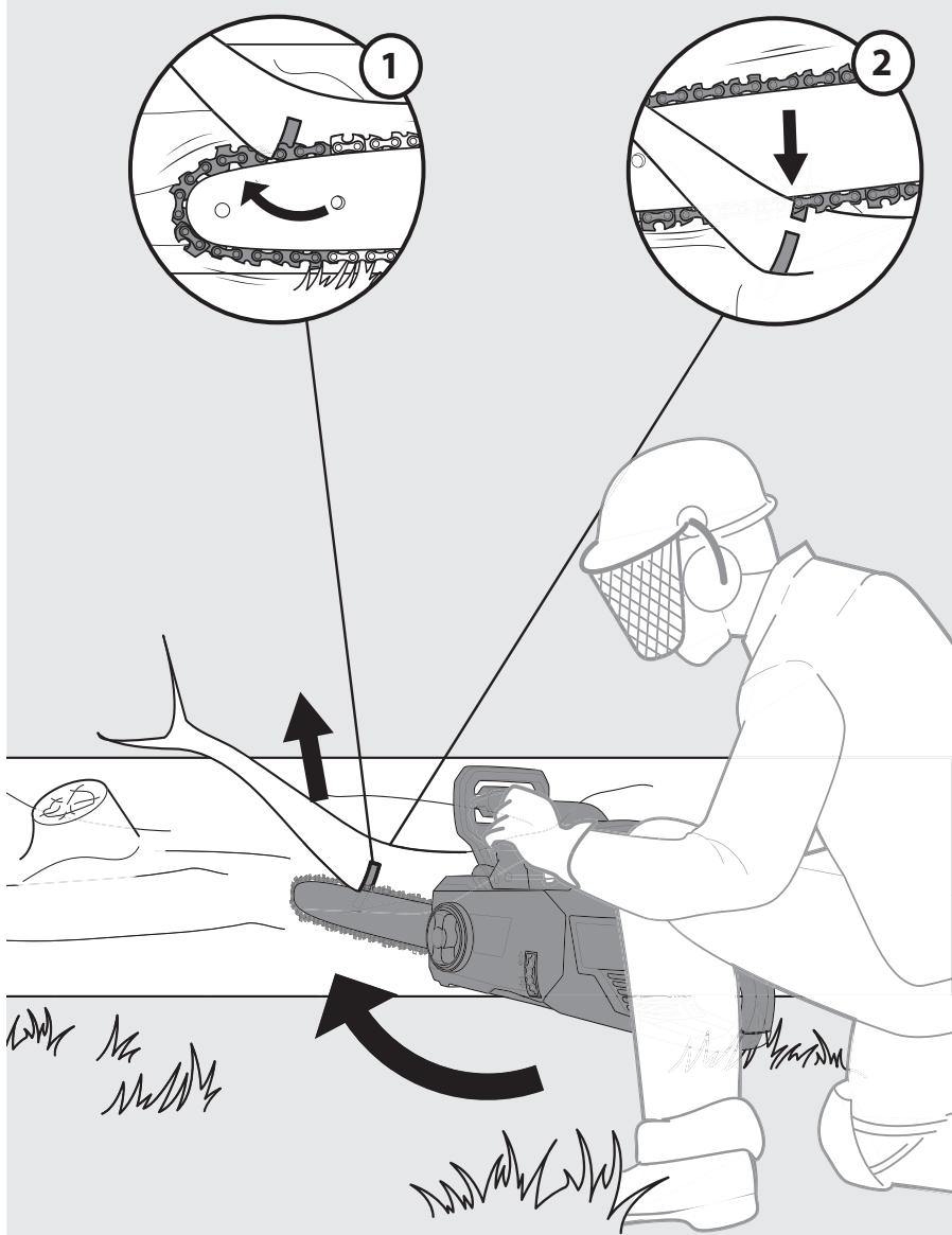
- Ensure the saw chain is running at full speed before it makes contact with the wood. Use spiked bumper to secure the product onto the wood before starting to cut and use it as a leverage point while cutting.
- Reset the spiked bumper at a low point when cutting thicker logs by pulling the product slightly backwards, until the gripping teeth release and re-position at lower level to continue sawing. Do not remove the product completely from the wood.
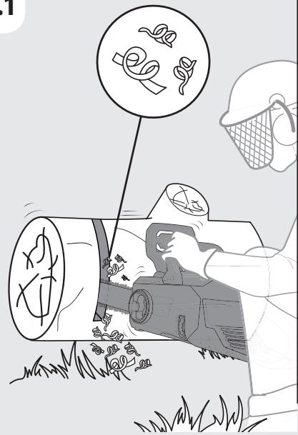
- Do not force the saw chain while cutting, let the chain do the work using the gripping teeth to apply minimal leverage pressure.
- Do not operate the product with arms fully extended or attempt to saw areas which are difficult to reach, or on a ladder. Never use the product above shoulder height.
- Optimum sawing is achieved if the chain speed remains constant during cutting.
- Be careful when reaching the end of the cut. The weight of the product may change unexpectedly as it cuts free from the wood. This can cause accidents to the legs and feet. Always remove the product from a wood cut while the product is running.
- Check that the oil feed to the chain is operating correctly; run the chain saw at medium speed and ensure that the chain has received a consistent coating of oil.
Preventing kickback
The term kickback refers to when the saw suddenly jumps up and back. This is usually caused by the work piece coming into contact with the chain bar tip or the clamping of the saw chain.
A kickback generates an abrupt powerful force. The saw usually reacts in an uncontrolled manner, creating the possibility of injury to the user.
The danger of a kickback is greatest when attempting to cut near or with the chain bar tip. Always apply the saw as flatly as possible in order to avoid a loss of control during operation.
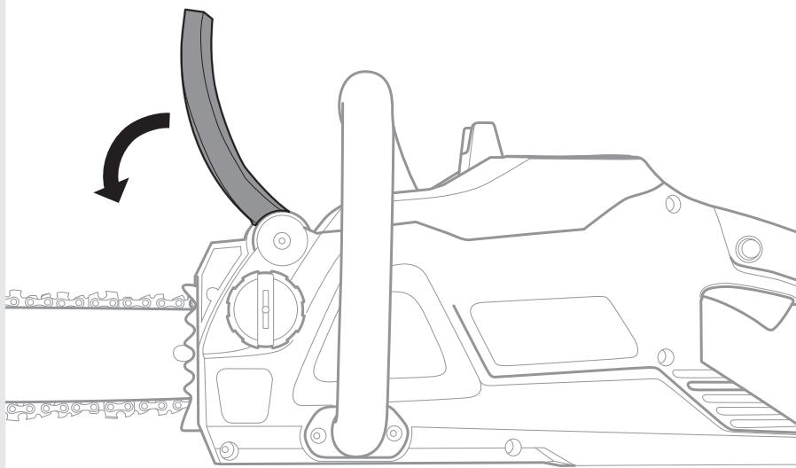
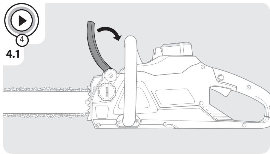
Kickback brake
The kickback brake is a safety mechanism activated by the front hand guard. When kickback occurs, the saw chain stops immediately.
The following function check should be carried out before each use. The purpose of the chain brake testing is to reduce the possibility of injury due to kickback:
- Push front hand guard forward and try to start the chain saw. The chain must not start.
- To deactivate the kickback brake, release ON/OFF trigger switch and pull hand guard backwards.
Felling a tree
WARNING! Before commencing work or attempting to fell any tree, check with your local council to ensure you have permission!
Even in your own garden you may be in a conservation area, the tree you wish to fell may have a conservation order against it or the tree may be visible on the plans of your house – In all these instances and more, you may be required to obtain permission before work can begin!
- When bucking and felling operations are being performed by two or more persons at the same time, the felling operations should be separated from the bucking operation by a distance of at least twice the height of the tree being felled. Trees should not be felled in a manner that would endanger any person, strike any utility line or cause any property damage. If the tree does make contact with any utility line, the company should be notified immediately.
- The product operator should keep on the uphill side of the terrain as the tree is likely to roll or slide downhill after it is felled.
- An escape path should be planned and cleared as necessary before cuts are started. The escape path should extend back and diagonally to the rear of the expected line of fall.
- Before felling is started, consider the natural lean of the tree, the location of larger branches and the wind direction to judge which way the tree will fall.
- Remove dirt, stones, loose bark, nails, staples and wire from the tree.
Notching undercut
Make the notch 1/3 the diameter of the tree, perpendicular to the direction of falls. Make the lower horizontal notching cut first. This will help to avoid pinching either the saw chain or the guide bar when the second notch is being made.
Felling back cut
- Make the felling back cut at least 50mm higher than the horizontal notching cut. Keep the felling back cut parallel to the horizontal notching cut. Make the felling back cut so enough wood is left to act as a hinge. The hinge wood keeps the tree from twisting and falling in the wrong direction.
Do not cut through the hinge. - As the felling gets close to the hinge, the tree should begin to fall. If there is any chance that the tree may not fall in the desired direction or it may rock back and bind the saw chain, stop cutting before the felling back cut is complete and use wedges of wood, plastic or aluminium to open the cut and drop the tree along the desired line of fall.
- When the tree begins to fall, remove the product from the cut, stop the motor, put the product down, and then use the retreat path planned. Be alert for overhead limbs falling and watch your footing.
Limbing and pruning
Limbing is removing the branches from a fallen tree. When limbing leave larger lower limbs to support the log off the ground. Remove the small limbs in one cut. Branches under tension should be cut from the bottom up to avoid binding the product.
WARNING! Never climb into a tree to limb or prune! Do not stand on ladders, platforms, logs, or in any position which may cause you to lose the balance or control of the saw! When pruning trees, it is important not to make the flush cut next to main limp or trunk until you have cut off the limb further out to reduce the weight! This prevents stripping the bark from the main member!
WARNING! If the branches to be pruned are above chest height, hire a professional to perform the pruning!
Cutting spring poles
- A spring pole is any log, branch, rooted stump, or sapling which is bent under tension by other wood, so that it springs back if the wood holding it is cut or removed.
- On a fallen tree, a rooted stump has a high potential of springing back to the upright position during the bucking cut to separate the log from the stump.
- Watch out for spring poles, they are dangerous.
Bucking a log
Bucking or cross-cutting is cutting a log into lengths. It is important to make sure your footing is firm and your weight is evenly distributed on both feet. When possible, the log should be raised and supported by the use of limbs, logs or chocks.
- Follow the simple directions for easy cutting. When the log is supported along its entire length, it is cut from the top (over buck).
- When the log is supported on one end, cut 1/3 the diameter from the underside (under buck). Then make the finished cut by over-bucking to meet the first cut.
- When the log is supported on both ends, cut 1/3 the diameter from the top (over buck). Then make the finished cut by under bucking the lower 2/3 to meet the first cut.
- When bucking on a slope always stand on the uphill side of the log. When "cutting through", to maintain complete control release the cutting pressure near the end of the cut without relaxing your grip on the product handles. Don't let the chain contact the ground. After completing the cut, wait for the saw chain to stop before you move the product. Always stop the motor before moving from tree to tree.
- Support small logs on a sawing stand or another log while bucking.
- If the wood diameter is large enough for you to insert a soft bucking wedge without touching the chain, you should use the wedge to hold the cut open to prevent pinching.
Vibration and noise reduction
To reduce the impact of noise and vibration emission, limit the time of operation, use low-vibration and low-noise operating modes as well as wear personal protective equipment.
Take the following points into account to minimise the vibration and noise exposure risks:
- Only use the product as intended by its design and these instructions.
- Ensure that the product is in good condition and well maintained.
- Use correct attachments for the product and ensure they are in good condition.
- Keep tight grip on the handle.
- Maintain this product in accordance with these instructions and keep it well lubricated (where appropriate).
- Plan your work schedule to spread any high vibration tool use across a longer period of time. To reduce this risk when using the product, always wear protective gloves and keep your hands warm.
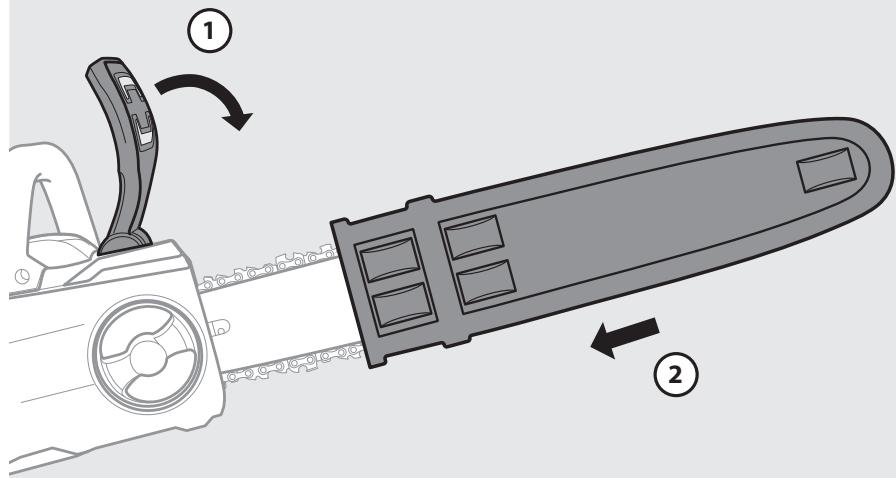
After use
Switch the product off and make sure that all moving parts have come to a complete stop. Attach the blade sheath. Remove the battery pack and let it cool down. Check, clean and store the product as described below.
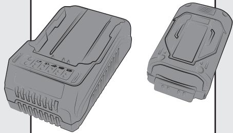
Removing and charging the battery : Illustration 5.2 and battery instruction manual
- Press the lock button on the top center of the battery to slide it out of the product.
- Place the battery pack into the charger by sliding it into a locked position until it clicks
- When the green light is flashing, the battery is charging. If the green light is no longer flashing, the battery is fully charged.
5. TRANSPORTATION
Transporting the machine or battery may require that you meet certain requirements specific to your country. Please make sure to respect them by contacting the authorities of your country, in order to respect them all. Ensure temperature during transportation will never be out of temperature range given on chapter storage
5.1 TRANSPORT THE MACHINE
Switch the product off, make sure that all moving parts have come to a complete stop and remove the battery pack. Always carry the product by its handle with the blade sheath attached. Protect the product from any heavy impact or strong vibrations which may occur during transportation in vehicles. Secure the product to prevent it from slipping or falling over. Do not expose the product to sunlight.
5.2 TRANSPORT THE LITHIUM BATTERIES
Please refer to the battery instruction manual for further details.
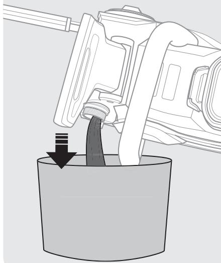
6. WINTERING
Illustration 6.1 to 6.3
Plug out the battery from the power tool.
Before long storage please ensure the battery charge fit to instructions provided on battery instruction manual. Follow all instructions given on chapter storage below. We recommend using the original package for storage or covering the product with a suitable cloth or enclosure to protect it against dust.
7. STORAGE
Only store the machine and the battery in a clean, dry, ventilated place with a temperature range of 4^ C to 24^ C. Cover it in order to provide added protection. We recommend using the original package for storage or covering the product with a suitable cloth or enclosure to protect it against dust. Be sure to secure the unit while transporting
7.1 STORE THE MACHINE
Illustration 6.3
Plug out the battery from the power tool. Examine the unit thoroughly for worn, loose or damaged parts. Clean the unit before storing. Do not expose the product to sunlight. Make sure the product is always protected from cold and humidity.
7.2 STORE THE LITHIUM BATTERIES
Please make sure that the battery power level is as recommended in the battery instruction manual. Please refer to the battery instruction manual for further details.
8. MAINTENANCE

DANGER! Risk of injury due to electric shock. Remove the battery pack and make sure that all moving parts have come to a complete stop before adjusting, inspecting, cleaning or storing the product.
8.1 CLEANING
Illustration 5.2 to 5.8
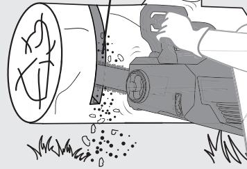
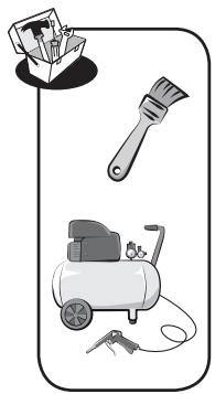
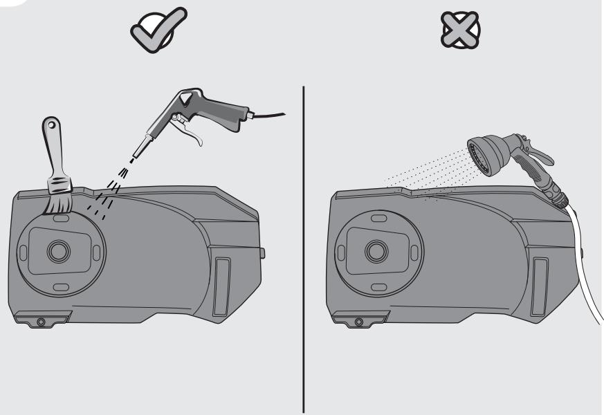
Keep all safety devices, air vents, and motor housing free of debris and dirt. Wipe down the equipment with a cloth and/or compressed air. It is highly suggested that you clean the product after every use.
Do not use cleaning agents, as these can attack the plastic and weaken the structural integrity of the chain saw.
Remove and brush clean the cover plate, chain and chain bar after 1 to 3 hours of use.
Clean the area under the cover plate, the drive sprocket and chain bar assembly using a soft brush.
Clean oil outlet with a clean cloth.
Do not place other objects on the chain saw.
8.2 REPLACEMENT
Illustration 5.1

WARNING! When handling saw chains, always wear protective gloves.
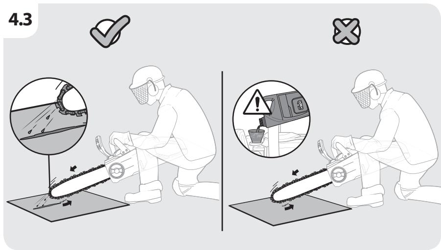
Checking the automatic chain lubrication
Regularly check the functionality of the automatic chain lubrication in order to prevent overheating and the subsequent damage to the chain bar and saw chain associated with it. For this purpose, align the chain bar tip against a smooth surface (board, cut-in of a tree) and allow the chain saw to run. If an increasing amount of oil appears, the automatic chain lubrication functions properly.
Lubricate sprocket
NOTE: It is not necessary to remove the chain or bar when lubricating the sprocket.
- Clean the bar and sprocket.
- Using a grease gun, insert the tip of the gun into the lubrication hole and inject grease until it appears at the outside edge of the sprocket tip.
- To rotate the sprocket release the chain stop and pull the chain by hand until the ungreased side of the sprocket is in line with the grease hole. Repeat the lubrication procedure.
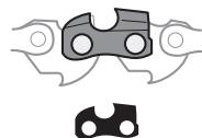
Sharpening the saw chain
Keep chain sharp. Your saw will cut faster and more safely. A dull chain will cause undue sprocket, guide bar, chain, and motor wear. If you must force chain into wood and cutting creates only sawdust with a few large chips, then chain is dull. Purchase a new chain, have your chain sharpened professionally at a qualified service center, or sharpen the chain yourself using a proper sharpening kit. The height difference between the cutting tip and the ridge is the depth gauge setting. When you sharpen the cutting tip, the depth gauge setting between the tip and the side plate ridge will decrease. To maintain optimal cutting performance, the ridge has to be filed down to achieve the recommended depth gauge setting.
To sharpen the chain :
- Using protective gloves, ensure the chain is correctly tensioned on the guide bar.
- Use a round file with a diameter 1.1 times the cutting tooth depth. Make sure 20% of the file diameter is above the cutter's top plate.
NOTE : A file guide is available from most chainsaw retailers and is the easiest way to hold the file at the correct position. - File at an angle perpendicular to the bar, and at an angle of 25^ to the direction of travel.
- File each tooth from the inside towards outside only. File one side of the chain first then turn the saw around and repeat the process.
- Sharpen each tooth equally by using the same number of strokes.
- Keep all cutter lengths equal. Each time the cutting tip is sharpened the cutting length is reduced. When the cutter length is reduced to 0.16 inch (4 mm), the chain is worn out and should be replaced.
• The depth gauge setting is also reduced with each sharpening. Every 5 sharpenings use a depth gauge measuring tool to check the height between the cutting tip and the ridge. When necessary, use a flat file to file down the ridge to achieve the .025 inch depth gauge setting. Depth gauge measuring tools are available from most chainsaws retailers. - If the saw is not functioning properly, take it to a qualified chainsaw service center to have the saw inspected. Use only identical parts as listed in this manual.
Replacing the saw chain and chain bar
Approved saw bar/saw chain
Replace chain when cutters are too worn to sharpen or when chain breaks. Only use replacement chain noted in this manual.
Always include new drive sprocket when replacing chain. This will maintain proper driving of chain.
- Place the saw body on a firm and level surface.
- Rotate the bar adjust locking knob anticlockwise to remove the cover from the saw's body.
- Wearing protective gloves, wrap the saw chain around the chain bar, making sure that the teeth are aimed in the direction of rotation. The chain should be properly set in the slot running along the entire outside edge of the chain bar.
- Place the saw chain around the sprocket) while lining up the slot in the chain bar with the internal bolt at the base of the saw and the chain tensioning pin in the chain bar's pin hole. The chain tensioning pin may need adjustment to properly align with the hole in the chain bar. Use the chain tensioning wheel to adjust its location until it fits in the chain bar.
- Turn the chain tensioning wheel to preliminarily tighten the chain bar enough that it stays in place. While holding the bar still, place the cover back onto the saw. Make sure the tab properly lines up with the slot on the body of the saw. Lock the cover in place with the cover locking knob by turning it clockwise until it engages. Adjust the chain tension.
8.3 EXPLODED VIEW
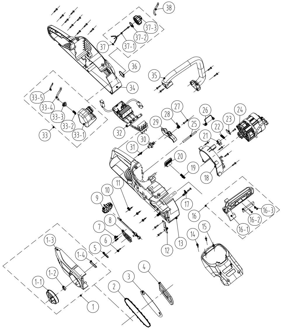
| POS | PART NUMBER | DESCRIPTION | NUM |
| 1-1 | 8313-438801 | Knob | 1 |
| 1-2 | 8334-463101 | Shaft Sleeve | 1 |
| 1-3 | 8021-438801 | Cover | 1 |
| 1-4 | 8208-438801 | End Cover Seal Ring | 1 |
| 2 | 243-0029 | Chain | 1 |
| 3 | 243-0065 | Chain board | 1 |
| 4 | 8331-430402 | Knife set | 1 |
| 1 | 8440-438801 | Adjust the end cap assembly | 1 |
| 5 | 8208-438301 | Oil-out seal ring | 1 |
| 6 | 8SJAB40-16 | Self tapping screw | 22 |
| 7 | 8SEAB40-12 | Self tapping screw | 2 |
| 8 | 8202-438801 | Heat insulation washer | 1 |
| 9 | 8313-436501 | Adjusting knob | 1 |
| 10 | 8440-491105 | Adjust lever assy | 1 |
| 11 | 8SJGN50-25 | Screw | 3 |
| 12 | 8181-433501-01 | Buffer Plate | 1 |
| 13 | 8006-438802-01 | Right housing | 1 |
| 14 | 8SJAB40-16 | Self tapping screw | 4 |
| 15 | 8020-438801 | Upper cover | 1 |
| 16 | 8440-438802 | Protection plate assembly | 1 |
| 16-1 | 8185-438801 | Preventer Plate | 1 |
| 16-2 | 8302-438801 | Impact Block | 1 |
| 16-3 | 8SJAB40-10 | Screws | 2 |
| 17 | 8440-431210 | Oil outlet joint assembly | 1 |
| 18 | 8024-438801 | Wind Guide cover | 1 |
| 19 | 8342-521704 | Button spring | 1 |
| 20 | 8044-780501-01 | Battery pack button | 1 |
| 21 | 8304-433201 | Locating piece | 1 |
| 22 | 8342-481501 | Brake lever spring | 1 |
| 23 | 8182-471902 | Pressure plate | 1 |
| 24 | 8440-438805-01 | Motor Oil pump assembly | 1 |
| 25 | 8081-438801 | Spring locating shaft | 1 |
| 26 | 8342-438801 | Battery box spring | 1 |
| 27 | 8SJAB30-25 | Self tapping screw | 1 |
| 28 | 8342-432101 | Switch torsion spring | 1 |
| 29 | 8312-438801 | Trigger | 1 |
| 30 | 8312-433501 | Button | 1 |
| 31 | 8342-463002 | Spring | 1 |
| 32 | 8414-438802 | Electronic components | 1 |
| 33 | 8440-438803 | Oil box assy | 1 |
| 33-1 | 8165-438801 | Fuel Tank | 1 |
| 33-2 | 8342-437501-02 | Filter The Spring | 1 |
| 33-3 | 8208-462503 | Oil Box Seal Ring | 1 |
| 33-4 | 234-1003 | Transparent Oil Tube | 90mm |
| 33-5 | 8342-000002 | Tubing Setting Spring | 60mm |
| 34 | 8006-438801-01 | Left housing | 1 |
| 35 | 8003-438801 | Front handle | 1 |
| 36 | 8341-491801 | Rubber washer | 1 |
| 37 | 8440-438807 | Oil box cap assy | 1 |
| 37-1 | 8088-438401 | Hanger | 1 |
| 37-2 | 8208-431901-01 | Sealing Ring | 1 |
| 37-3 | 8020-438802 | Oil Box Cap | 1 |
| 38 | 234-1003 | Transparent oil tube | 120mm |
8.4 TROUBLESHOOTING

DANGER! Risk of injury due to electric shock. Warning! Before any trouble shooting, switch off the product.
| Problems | Probable causes | Solutions | Qualification required |
| Product does not start | Battery is not secure | To secure the battery pack, make sure the latches on the top of the battery pack snap into place | - |
| Battery is not charged | Charge the battery pack according to the instructions included with your model | ||
| Power/speed switch is in the OFF position | Press the on/off switch | ||
| Battery pack not properly attached | Attach properly | ||
| On/off switch not set on ON position | Refer to chapter "Switching on/off" | ||
| Chain brake is activated | Disengage the chain brake (see section "Kickback brake") | ||
| Product does not reach full power | Battery pack capacity too low | Charge battery pack | - |
| Air vents are blocked | Clean the air vents | ||
| Vibration or noise is excessive | Bolts/nuts are loose | Tighten bolts/nuts | - |
| Saw chain is dull/damaged | Have it replaced with a new one | - | |
| Result is unsatisfactory | Blunt saw chain | Sharpen or re-place the saw chain | - |
| - | |||
| Saw chain not tensioned properly | Tension it properly | - | |
| Product suddenly stops | Battery pack discharged | Remove and charge battery pack | - |
| Battery too hot | Remove battery pack and let it cool down | ||
| Product maybe over current* | Stop the product and wait for 3 minutes to restart |
*Over current means "Self-protection". "Self-protection" mode is a degraded mode, limited in time (we recommend a maximum duration of 5 minutes) during which the use of the product is made impossible so that the product can recover its initial state.
9. END OF LIFE

Electrical products should not be discarded with household products. Used electrical products must be collected separately and disposed of at collection points provided for this purpose. Talk with your local authorities or dealer for advice on recycling.
10. WARRANTY
10.1 OUR WARRANTY
STERWINS products are designed according to the highest quality standards for products intended for the consumer market. This sale warranty covers a period of 3 years as of the date of purchase of the product. This warranty covers all defects in materials and workmanship: missing parts and elements, and damage occurring under normal use circumstances. Repair and replacement of parts do not lead to an extension of the initial warranty period. You must be able to provide proof of the purchase for this product and the date of purchase. Warranty coverage is limited to the value of this product.
10.2 WARRANTY EXCLUSIONS
This warranty does not cover problems nor incidents resulting from incorrect use of the product. The following items are not covered by warranty :
- The tool have been used incorrectly; or
- Damage occurring upon transporting or setting up this product; or
- Repairs and/or change of parts carried out by a third party; or
- Damage caused by external factors or foreign objects such as sand or stones; or
- Damage resulting from non-compliance with the safety and usage instructions; or
- The tool have been disassembled or opened; or
- The tool have been in a wet environment (dew, rain, submerged in water...); or
- The tool has been used for professional purpose; or
- The tool has been exposed to a temperature out of the range specified in chapter "storage"
The product must be used under normal usage circumstances, and for non-professional purposes. Therefore, excluded from this warranty are products used by gardening companies, local authorities, as well as companies offering paid rentals or free loaning of equipment.
In the event of a problem or defect, you should first always consult your Sterwins dealer. In most cases, the Sterwins dealer will be able to solve the problem or correct the defect. Keep your invoice or your receipt: these documents will be requested upon processing any claims.
amending Directive 2011/65/EU
IEC 62321-1:2013
IEC 62321-2:2013
IEC 62321-3-1:2013
IEC 62321-4:2013+A1:2017
IEC 62321-5:2013
IEC 62321-6:2015
IEC 62321-7-1:2015
IEC 62321-8:2017
IEC 62321-7-2:2017&ISO 17075-1:2017
EN IEC 63000:2018
ISO 9207:1995
EN ISO 3744:1995
EN ISO 3744:2010
2000/14/EC Annxe V as amended by 2005/88/EC
When applicable, the name and number of notified body number[Le cas échéant, le nom et le numérp de l'organisme notifié]Cuando corresponda * el nombre y número de laboratorio notificado que haya emitido la certificación y la referencia al documento|Quando aplicável * o nome e número do laboratório notificado que emitiu a certificação e a referência ao documento]
Certificate no:MD-280 Issue 1
Notified body: SGS Fimko Ltd
Address : Takomotie 8,Fl-00380 Helsinki,Finland
Number of notified body:0598
Measured sound power level: 100.12dB(A)
Guaranteed sound power level: 104dB(A)
Signed for and on behalf of|Signé par et au nom de|Firmado por y en nombre de|Assinado por e em nome de:|
Place and date of issue|Date et lieu d'établissement|Lugar y fecha de expedición|Local e data de emissão|
Eric LEMOINE
International Project Quality Leader
Ronchin
25/03/2022
La presente dichiarazione di conformità è rilasciata sotto la responsabilità esclusiva del fabbricante|Niniejsza deklaracja zgodności wydana zostaje na wyłączną odpowiedzialność producenta.|Επωνυμία και διεύθυνση του κατασκευαστή ή του εξουσιοδοτημένου αντιπροσώπου του|Denumirea și adresa producătorului sau a representantului său autorizat:|
ADEO Services, 135 Rue Sadi Carnot - CS 00001 59790 RONCHIN - France
La presente dichiarazione di conformità è rilasciata sotto la responsabilità esclusiva del fabbricante|Niniejsza deklaracja zgodności wydana zostaje na wyłączną odpowiedzialność producenta.|H παρούσα δήλωση συμμόρφωσης εκδίδεται με αποκλειστική ευθύνη του κατασκευαστή|Declaratía de conformitate este emisã pe rãspunderea exclusivã a producátorului|
amending Directive 2011/65/EU
IEC 62321-1:2013
IEC 62321-2:2013
IEC 62321-3-1:2013
IEC 62321-4:2013+A1:2017
IEC 62321-5:2013
IEC 62321-6:2015
IEC 62321-7-1:2015
IEC 62321-8:2017
IEC 62321-7-2:2017&ISO 17075-1:2017
EN IEC 63000:2018
ISO 9207:1995
EN ISO 3744:1995
EN ISO 3744:2010
2000/14/EC Annxe V as amended by 2005/88/EC
Dove applicabile * il nome e il numero del laboratorio notificato che ha rilasciato la certificazione e il riferimento al documento|W stosownych przypadkach * notylikowana nazwa i numer laboratorium, które wydalo certifikat oraz odniesienie do dokumentu|Omou iαχύει * to γνωστοποιημένο όνομα και τον αριθμό του εργαστηρίου του εξέδωσε την πιστοποιηση και την αναφορά στο έγγραφο|Unde este cazul * numele și numărul de laborator notificat care a eliberat certificarea și trimiterea la document|
Certificate no:MD-280 Issue 1
Notified body: SGS Fimko Ltd
Address : Takomotie 8,FI-00380 Helsinki,Finland
Number of notified body:0598
International Project Quality Leader
Ronchin
25/03/2022
Measured sound power level: 100.12dB(A) Guaranteed sound power level: 104dB(A)
natural_image
Technical illustration of a mechanical device with handle and control panel (no text or symbols)
natural_image
Illustration of a chain with chain links, no text or symbols present
natural_image
Simple gray oval shape with a circular label containing the letter 'C' and four small circles on its sides (no text or symbols within the shape)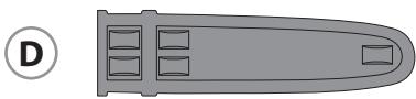
natural_image
Top-down diagram of a gray elongated object with internal compartments, labeled with circled number D (no text or symbols on the object itself)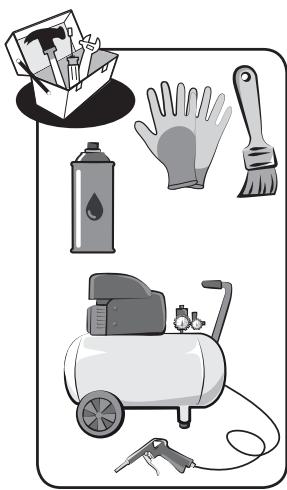
natural_image
Illustration of various cleaning and cleaning tools including a spray can, gloves, brushes, an air conditioner, and a tool (no text or symbols present)

UNIVERSAL* POWER

natural_image
Two technical illustrations of a battery pack with mounting holes and internal compartments (no text or symbols)
natural_image
Illustration of a hand washing machine with an open envelope and a paper airplane above it (no text or symbols)
2.1
natural_image
Diagram of a car air conditioner unit with a hand inserting a component (no text or symbols)2.2
2.3


natural_image
Illustration of a hand holding a small object above it, with no visible text or symbols.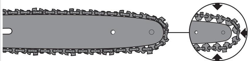
natural_image
Diagram of a chain-link robotic device with gear mesh and circular motion arrows indicating movement (no text or symbols)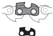
natural_image
Pure mechanical component diagram without any text, numbers, or symbols
natural_image
Two abstract mechanical components with circular features, one gray and one black, shown without any text or symbols.
2.4
2.5

natural_image
Icon showing a checkmark inside a circle with a pen and number 3, no text or symbols present.3.1

3.2
natural_image
Technical line drawing of a mechanical assembly with chain and gear components (no text or symbols)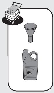
natural_image
Illustration of a shopping cart, funnel, and spray bottle (no text or symbols)3.3
natural_image
Illustration of two electronic components with a shopping cart icon above (no text or symbols)3.4
4.4
4.5
a
b

natural_image
Simple line drawing of a shopping cart with a chain and chain loop, no text or symbols present
natural_image
Illustration of a sponge with a droplet and sparkles, enclosed in a circular frame (no text or symbols)


natural_image
Simple diagram with a circle containing scattered black dots and two irregularly shaped outlines (no text or symbols)
5.1
natural_image
Illustration of a person operating a large cylindrical device with tools and leaves, no text or symbols present
natural_image
Illustration of a person using a power tool to clean or brush with scattered dots, no text or symbols present
After sales


52PCS

17PCS

3/8"
9.525mm

0.050"
1.27 mm
5.2
2

natural_image
Illustration of cleaning tools including a brush, a pressure cooker, and a paper holder (no text or symbols)5.3
5.4
natural_image
Illustration of a hand holding a small object above it, enclosed in a rounded square frame (no text or symbols)5.5
natural_image
Technical line drawing of a chain-linking device with gear and chains (no text or symbols)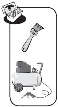
natural_image
Illustration of cleaning tools including a paintbrush, air purifier, and key (no text or symbols)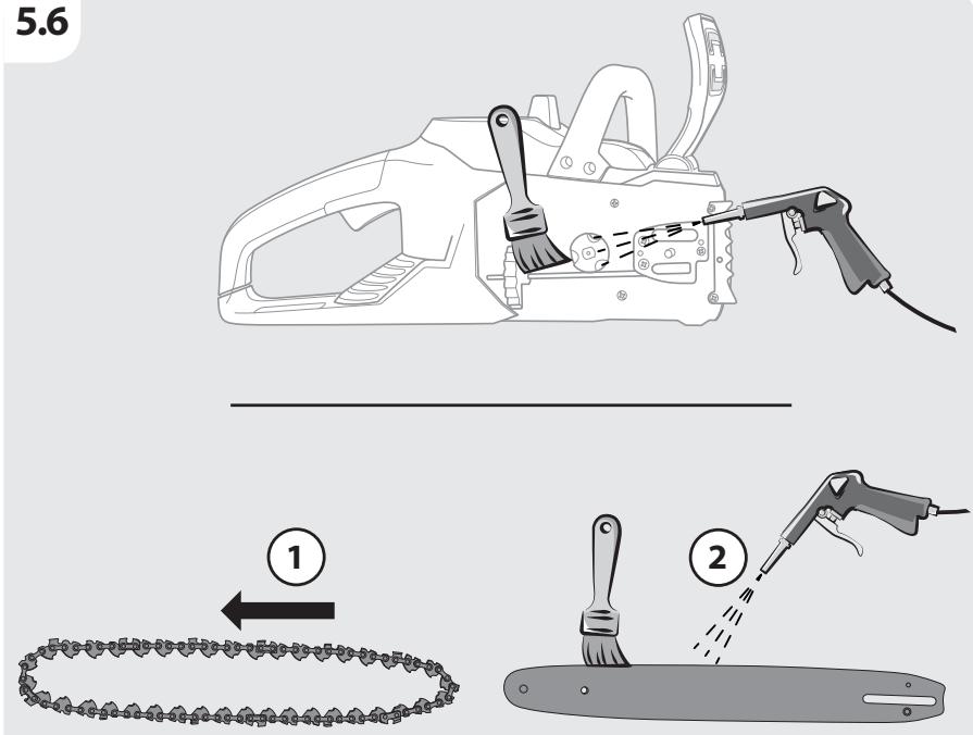
5.7
natural_image
Illustration of a USB flash drive with a D button and sparkles (no text or symbols)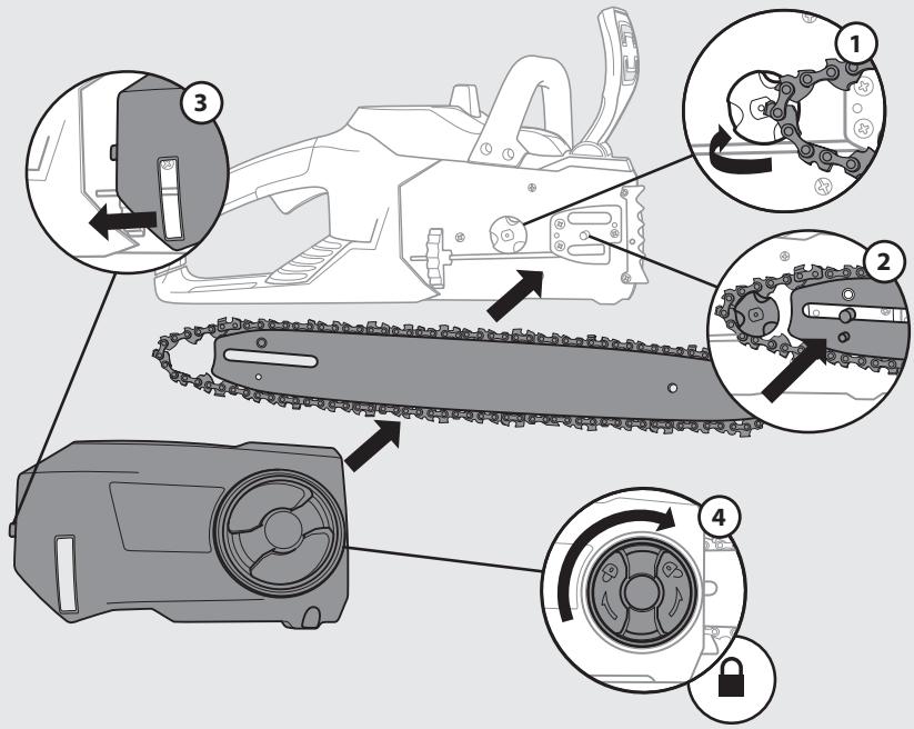
5.8

natural_image
Simple line drawing of a spray can and a paper stack with a droplet, enclosed in a rounded square frame (no text or symbols)
natural_image
Simple line icon depicting a house with water droplet, snowflake, and number 6 (no text or symbols)6.1
natural_image
Diagram of a mechanical device pouring liquid into a container (no text or symbols)6.2

EN This product is recyclable. If it cannot be used anymore, please take it to waste recycling centre.
CE
EAC


natural_image
Illustration of a globe with multiple flags flying around it, no text or symbols present.Made in China / Зробпено в Китаї / Сделано в Китае / Кытайда жасапған

SA Imported by Adeo South Africa (PTY) LTD T/A Leroy Merlin, Hosted in Leroy Merlin Fourways Store 35 Roos Street, Witkoppen Ext 97, Sandton, 2191 Johannesburg, Gauteng, South Africa Tel: +27 10 493 8000 Email: contact@leroymerlin.co.za

- A NOSSA GARANTIA
- SYMBOLE NA PRODUKCIE
- BEZPIECZEŃSTWO W MIEJSCU PRACY
- NASZA GWARANCJA
- IMPORTANT, KEEP THE MANUAL FOR LATER REFERENCE : READ CAREFULLY
- Contents
- INTENDED USE OF BATTERY CHAIN SAW 34 CM
- SAFETY INSTRUCTIONS
- GENERAL SAFETY WARNINGS
- SYMBOLS ON THE PRODUCT
- SYMBOLS IN THIS MANUAL
- GENERAL POWER TOOL SAFETY WARNINGS
- WORK AREA SAFETY
- ELECTRICAL SAFETY
- PERSONAL SAFETY
- POWER TOOL USE AND CARE
- BATTERY TOOL USE AND CARE
- SERVICE
- CHAIN SAW SAFETY WARNINGS:
- CAUSES AND OPERATOR PREVENTION OF KICKBACK:
- RESIDUAL RISKS
- ASSEMBLY
- UNBOXING
- INSTALLATION
- Installing/Removing the battery pack : illustration 3.4
- Assemble the guide bar and the saw chain : illustration 2.1 to 2.5
- Tensioning the chain : illustration 2.5
- Note: The saw chain must be tensioned properly in order to ensure safe operation.
- PREPARATION
- Chain saw :
- Chain oil :
- Saw chain :
- Safety equipment and protective clothing :
- Filling the auto oil system : illustration 3.3
- FIRST USE
- OPERATION
- Switching on/off : illustration 4.2
- We strongly recommend that before use of this product, you attend a chainsaw training course to familiarise yourself with the maintenance and usage of these products! Thoroughly read this manual and adhere to all safety instructions at all times. The manufacturer will not be held liable for any accidents/injuries caused due to misuse or incorrect maintenance of this product!
- Preventing kickback
- Kickback brake
- Felling a tree
- Notching undercut
- Felling back cut
- Limbing and pruning
- Cutting spring poles
- Bucking a log
- Vibration and noise reduction
- After use
- Removing and charging the battery : Illustration 5.2 and battery instruction manual
- TRANSPORTATION
- TRANSPORT THE MACHINE
- TRANSPORT THE LITHIUM BATTERIES
- WINTERING
- Illustration 6.1 to 6.3
- STORAGE
- STORE THE MACHINE
- Illustration 6.3
- STORE THE LITHIUM BATTERIES
- MAINTENANCE
- CLEANING
- Illustration 5.2 to 5.8
- REPLACEMENT
- Illustration 5.1
- Checking the automatic chain lubrication
- Lubricate sprocket
- Sharpening the saw chain
- To sharpen the chain :
- Replacing the saw chain and chain bar
- TROUBLESHOOTING
- END OF LIFE
- WARRANTY
- OUR WARRANTY
- WARRANTY EXCLUSIONS
- IEC 62321-1:2013
- ISO 9207:1995
- Certificate no:MD-280 Issue 1
- Measured sound power level: 100.12dB(A)
- Eric LEMOINE
- Ronchin
- ADEO Services, 135 Rue Sadi Carnot - CS 00001 59790 RONCHIN - France
Brand : STERWINS
Model : UP40 - 40VCS2-34.1
Category : Chain saw