USER MANUAL Projecteur extérieur à LED LIVARNO
List of pictograms used.
Introduction.
Intended use Page 16
Parts description. Page 17
Technical data.. Page 17
Scope of delivery.. Page 17
General safety instructions Page 17
Before installation.. Page 18
Installation Page 18
Prior to first use. Page 19
Adjusting the motion detector. Page 19
Configuring the lighting duration.. Page 19
Configuring the sensitivity of the sensor.. Page 19
Configuring the daylight level. Page 19
Aligning the motion detector. Page 19
Cleaning and care.. Page 20
Disposal
Warranty and service.. Page 20
Service address.. Page 20
Manufacturer. Page 21
| List of pictograms used |
| i | Read the instructions! | | Ground conductor/protection class I |
| ! | Observe warnings and safety information! | IP54 | Protected against damaging quantities of dust and against spray water from all directions |
| Danger to life and risk of accidents for infants and children! | | Detection angle of motion detector: approx. 180° |
| Warning! Danger of electric shock! | | Pivoting motion detector |
| V | Volt | | Disposition of the packaging and product in an environmentally-friendly manner! |
| ~ | Alternating current/voltage | | Safety notices
Instructions for use |
| L | Conductor connection | N | Neutral conductor |
| The product incl. accessories and packaging materials are recyclable and are subject to extended producer responsibility. Dispense them separately, following the illustrated Info-tri (sorting information), for better waste treatment.
The Triman logo is valid in France only. |
LED Outdoor Light
Introduction

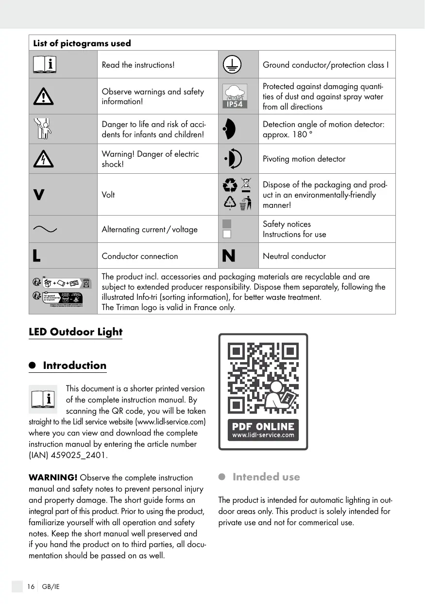
This document is a shorter printed version of the complete instruction manual. By scanning the QR code, you will be taken
straight to the Lidl service website (www.lidl-service.com) where you can view and download the complete instruction manual by entering the article number (IAN) 459025_2401.
WARNING! Observe the complete instruction manual and safety notes to prevent personal injury and property damage. The short guide forms an integral part of this product. Prior to using the product, familiarize yourself with all operation and safety notes. Keep the short manual well preserved and if you hand the product on to third parties, all documentation should be passed on as well.

- Intended use
The product is intended for automatic lighting in outdoor areas only. This product is solely intended for private use and not for commercial use.
Parts description
1 Spotlight
2 Wall plug
3 Fixing screw
4 Cover stopper (fixing screws)
5 Motion detector
6 Securing strip (connection cable)
7 Screw (fastening plate)
8 Fastening plate
Cover stopper (opening the fastening plate)
10 Terminal clamp
TIME rotary control (duty cycle)
[12] SENS rotary control (sensitivity)
[13] LUX rotary control (light sensitivity)
Technical data
Model no.: 10710LA/10710LB
Operating voltage: 220-250V\~, 50/60Hz, 20W
LEDs: 32 × LED (The LEDs are not replaceable.)
Dimming switch: adjustable from 2lx-20,000lx
Lighting duration: adjustable between approx. 5s-5min
Protection class:
Protection type: IP54 (protected against damaging quantities of dust and also against spray water from all sides)
Dimensions
(LxWxH): approx.16x13.1x 11.9cm
Projection area: max. 16 × 11.9cm
Installation height: ca. 2-3 m
Motion detector range: approx. 12m
Luminous flux: 2100lm
Colour temperature: approx. 3000K (warm white)
This product contains an illuminant from energy efficiency category "F".
- Scope of delivery
1 LED-outdoor spotlight with motion detector
2 wall plugs ( 6mm)
2 screws
1 cover stopper
1 set of assembly instructions and instructions for use

General safety instructions
Before using the product, please familiarise yourself with all of the safety information and instructions for use! When passing this product on to others, please also include all the documents!

DANGER TO LIFE AND ACCIDENT HAZARD FOR TODDLERS AND SMALL CHILDREN! Never
leave children unattended with the packaging material. The packaging material represents a danger of suffocation. Children frequently underestimate the dangers. Please keep children away from the product at all times.
This product may be used by children age 8 years and up, as well as by persons with reduced physical, sensory or mental capacities, or lacking experience and/or knowledge, so long as they are supervised or instructed in the safe use of the product and understand the associated risks. Children should not be allowed to play with the product. Cleaning and user maintenance should not be performed by children without supervision.

Risk of electric shock
Always check product for damage before connecting it to power. Never use the product if it shows any signs of damage.
Prior to installation, verify that the mains voltage on site corresponds with the operating voltage required for the product (220-250V~ 50/60Hz). Otherwise do not install the product.
CAUTION! DANGER OF BURN INJURIES! To prevent burns, verify the product is
switched off and has cooled down for at least 15 min before touching it. The product can become very hot.

FIRE HAZARD! Fit the product so that it is at least 0.5m away from the material to be illuminated.
Excessive heat can result in a fire.
This product does not contain any parts that can be serviced by the user. The LEDs and built-in LED control gear cannot be replaced by end user.
If the LEDs fail at the end of their lives, they must be repaired by qualified electrician or the entire product must be replaced.
The spotlight is only suited for use with the built-in LED control gear.
- Before installation
Important: The electrical connection must be established by a qualified electrician or a person trained to perform electrical installations. This person must be familiar with the properties of the product and the connection regulations.
Note: Remove all packaging materials from the product.
Before installation ensure that the circuit, to which the product will be connected, is not energised. To do so, remove the fuse or switch off the circuit breaker in the fuse box (0 position).
Use the voltage tester to verify the de-energised status.
The included mounting material is suitable for ordinary solid concrete or masonry construction. Check which mounting material is suitable for your chosen mounting surface. If necessary, seek expert advice.
- Installation
Make sure you will not be drilling into electrical, gas or water lines inside the wall. Use a power drill to drill the holes into the brick wall. Always observe all safety instructions for the power drill
in the manual for the power drill. Death or injury due to electric shock may otherwise result.
When selecting the mounting location, pay attention to the following:
Make sure that the spotlight 1 illuminates the desired area. You can move the spotlight 1 horizontally and vertically.
Make sure the motion detector 5 covers the desired area. The motion detector 5 has a maximum detection range of 12m, with a detection angle of about 180^ (depending on the mounting height - a height of 2-3m is ideal) (Fig. J).
Make sure the motion detector [5] is not illuminated at night by street lighting. This can influence its functioning.
To mount, proceed as described below:
Loosen the screw 7 beneath the fastening plate 8 using a cross-head screwdriver, then remove the fastening plate 8 (Fig. A).
Hold the fastening plate 8 so that it is horizontal against the wall (check with a spirit level if necessary) and mark out the fastening holes (Fig. B).
Now drill the fastening holes ( 6mm) and put the wall plugs into the fastening holes (Fig. B).
Remove the securing strip 6 for the connection cable by loosening both screws.
Push the 3× 1.00mm^2 connection cable (not included), such as a H05RN-F 3G 1.0mm^2 (Fig. C), through the round cover stopper on the fastening plate.
- Attach the fastening plate 8 to the wall using the fixing screws 3 supplied, then check that it is secure.
□ Afterwards, cover the fixing screws 3 with the cover stopper 4 (Fig. C).
Guide the connection cable upwards so that it is placed between the threads on the securing strip 6 . Fix the connection cable in this position by attaching the securing strip 6 , inserting it and then tightly screwing both screws into position (Fig. D).
Open the terminal clamp 10 located within the housing by loosening the screws with a slotted
screwdriver. Connect the connection cable to the terminal clamp 10 . Pay attention to the markings alongside the connections on the terminal clamp 10 (L for live, N for neutral and 1 or G for the ground/earth wire) (Fig. D). The total length of the connection cable should not exceed 2.5m .
- Close the terminal clamp 10 once again by tightening the screws (Fig. E).
Place the product on top of the fastening plate at an angle from above, then fix it into position by inserting the screw below the fastening plate and tightening it (Fig. F).
Align the spotlight into the desired direction. The motion detector can be rotated horizontally and vertically (Fig. G).
Reinsert the fuse or switch the circuit breaker back on. Your product is now ready to use (Fig. H).
Prior to first use
Adjusting the motion detector
Depending on the pre-adjustments of the motion detector 5, the spotlight 1 will switch itself on for a certain period of time as soon as the motion detector 5 detects movement. These pre-adjustments are made using the three controllers on the rear side of the motion detector 5 (Fig. 1).
- Configuring the lighting duration
Turn the TIME rotary control 11 clockwise to increase the lighting duration. The lighting duration can be configured within a time window of approx. 5 seconds to 5 minutes.
- Configuring the sensitivity of the sensor
Turn the SENS rotary control 12 clockwise to increase the sensitivity of the sensor. The
motion detector 5 can detect movements at a distance of up to 12m on its maximum setting.
Note: The motion detector 5 responds to heat radiation. When outdoor temperatures are low, it is more sensitive to body heat than when outdoor temperatures are warm. Be sure to regulate the sensitivity of the sensor over the course of the year.
- Configuring the daylight level
Turn the LUX rotary control 13 clockwise to increase the daylight level: The daylight level can be set from 2lx which is functional at night, to 20,000lx. The motion detector 5 then also works in daylight on the maximum setting, provided that it does not exceed 20,000lx.
Aligning the motion detector
Note: Perform this adjustment at twilight.
Turn the LUX rotary control [13] all the way to the right.
- Point the motion detector 5 to the central region of the desired detection area.
Move about through the detection area until you are satisfied with the response of the motion detector [5]. To find the proper orientation, change the position of the SENS rotary control [12] or the orientation of the motion detector [5].
Note: Please observe that the motion detector 5 primarily detects movements transverse to the motion detector 5. If you move directly towards the motion detector 5, it cannot detect this movement.
If you have set up the motion detector 5 as desired, turn the LUX rotary control 13 to the desired position. You can also determine the desired position of the LUX rotary control 13 in which the spotlight 1 will act during dusk and dawn.
Slowly turn the LUX rotary control [13] anticlockwise until the motion detector [5] reacts to movements within the detection area.
- Cleaning and care
Before cleaning, remove the fuse or switch off the circuit breaker at the fuse box.
Never immerse the product in water or other liquids. Otherwise the product can be damaged.
Clean the product with a lint-free, slightly moist cloth and mild cleaning agent.
Reconnect the fuse or circuit breaker for use after cleaning.
- Disposal
The packaging is made entirely of recyclable materials, which you may dispose of at local recycling facilities.

Observe the marking of the packaging materials for waste separation, which are marked with abbreviations (a) and numbers (b) with following meaning: 1-7: plastics/20-22: paper and fibreboard/80-98: composite materials.

Contact your local refuse disposal authority for more details of how to dispose of your worn-out product.

To help protect the environment, please dispose of the product properly when it has reached the end of its useful life and not in the household waste. Information on collection points and their opening hours can be obtained from your local authority.

The product incl. accessories and packaging materials are recyclable and are subject to extended producer responsibility. Dispose them separately, following the illustrated Info-tri (sorting information), for better waste treatment. The Triman logo is valid in France only.
Warranty and service
Note: This product includes a 36 month warranty from the date of purchase. The product has been produced to the highest standards and thoroughly checked before dispatch. However, if defects in manufacturing or material arise during the warranty period, please contact your retailer immediately.
The warranty does not cover damages due to improper handling, failure to comply with the instructions for use, or manipulation by unauthorised persons. Most malfunctions are caused by incorrect operation. Therefore, please first refer to the instructions for use if a malfunction occurs.
Please contact the Uni-Elektra GmbH service address with any questions. The product can only be returned to us after contacting us. Postage due shipments will not be accepted. Warranty services do not extend or restart the warranty period of 36 months.
Service address
Uni-Elektra GmbH
Hummelbergstr. 6
Please have your receipt and the item number (IAN 459025_2401) ready as your proof of purchase when enquiring about your product.
Manufacturer
Uni-Elektra GmbH
Hummelbergstr. 6
LB052024-OSDE/OSFR/OSNL/OSBE