VEIL TIBETAN - Range hood FABER - Free user manual and instructions
Find the device manual for free VEIL TIBETAN FABER in PDF.
| Product type | Decorative range hood |
| Brand | FABER |
| Model | VEIL TIBETAN |
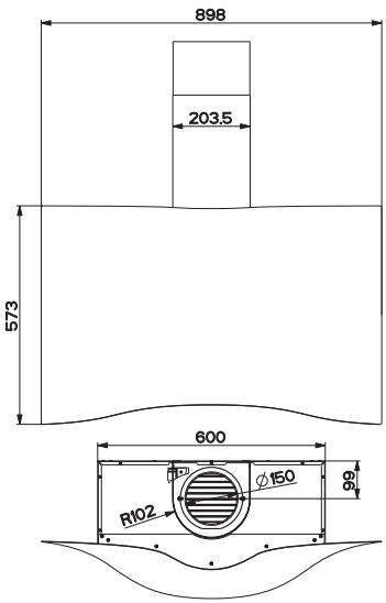
| Dimensions (W x D x H of body) | 898 x 573 x 203 mm (approximate) |
| Minimum mounting height above the cooktop | 650 mm |
| Air outlet diameter | 150 mm (reducible to 120 mm) |
| Number of speeds | 4 (including 6-minute delay on 4th speed) |
| Integrated lighting | Yes (controlled by L button) |
| Type of grease filters | Self-supporting metallic, dishwasher safe |
| Cleaning frequency of grease filters | Every 2 months (or more depending on use) |
| Activated carbon filter | Optional, replacement every 4 months |
| Operating mode | Ducted or recirculating depending on installation |
| Power supply | 220-240 V ~ 50/60 Hz (standard estimate) |
| Electrical class | I (grounding mandatory) |
| Main material | Stainless steel (probable) |
| Included accessories | Telescopic chimney, air outlet grille, reduction collar, screws and wall plugs, manual |
| Minimum safety distance for gas cooking | Refer to the cooktop instructions (if >650 mm) |
| Delay function | Automatic stop after 6 minutes on 4th speed |
| Filter maintenance | Grease filters dishwasher safe; charcoal filters not washable |
| Repairability | Spare parts available through authorized after-sales service |
Frequently Asked Questions - VEIL TIBETAN FABER
User questions about VEIL TIBETAN FABER
0 question about this device. Answer the ones you know or ask your own.
Ask a new question about this device
Download the instructions for your Range hood in PDF format for free! Find your manual VEIL TIBETAN - FABER and take your electronic device back in hand. On this page are published all the documents necessary for the use of your device. VEIL TIBETAN by FABER.
USER MANUAL VEIL TIBETAN FABER
natural_image
Technical line drawing of a mechanical assembly with a cylindrical component mounted on a base plate (no text or symbols)Libretto di Istruzioni Instructions Manual Bedienungsanleitung Manuel d'Instructions Manual de instrucciones Instrukcja Obsługi Руководство по эксплуатации Εγχειρίδιο οδηγιών Käyttöohje
Brugsvejledning Bruksanvisning Priročnik za uporabo Príručka na obsluhu Uputstva za Korištenje Uživatelská Pøíruèka Инструкции Ръководство دليل التركيب
INDICE
IT
SAFETY INFORMATION......14
CHARACTERISTICS 17
INSTALLATION....18
USE 21
CARE AND CLEANING 22
INHALTSVERZEICHNIS
DE
CARACTERISTIQUES....35
INSTALLATION....36
UTILISATION 39
NETTOYAGE ET ENTRETIEN 40
INDICE
ES
natural_image
Line drawing of a hand using a tool to measure a circular component (no text or symbols)
CONNESSIONE ELETTRICA
natural_image
Diagram showing a mechanical component with a green arrow indicating motion, no text or symbols present

Quadro comandi
natural_image
Illustration of a hand pressing a green arrow on a smartphone screen (no text or symbols)natural_image
Diagram of a mechanical device with rotating components and green arrows indicating motion (no text or symbols)
natural_image
Diagram of a mechanical or fluidic device with green arrows indicating flow direction (no text or symbols)Illuminazione
For your safety and correct operation of the appliance, read this manual carefully before installation and use. Always keep these instructions with the appliance even if you move or sell it. Users must fully know the operation and safety features of the appliance.
⚠ The wire connection has to be done by specialized technician.
- The manufacturer will not be held liable for any damages resulting from incorrect or improper installation.
- The minimum safety distance between the cooker top and the extractor hood is 650 mm (some models can be installed at a lower height, please refer to the paragraphs on working dimensions and installation).
- If the instructions for installation for the gas hob specify a greater distance, this must be respected.
- Check that the mains voltage corresponds to that indicated on the rating plate fixed to the inside of the hood.
- Means for disconnection must be incorporated in the fixed wiring in accordance with the wiring rules.
- For Class I appliances, check that the domestic power supply guarantees adequate earthing.
- Connect the extractor to the exhaust flue through a pipe of minimum diameter 120 mm. The route of the flue must be as short as possible.
• Regulations concerning the discharge of air have to be fulfilled. -
Do not connect the extractor hood to exhaust ducts carrying combustion fumes (boilers, fireplaces, etc.).
-
If the extractor is used in conjunction with non-electrical appliances (e.g. gas burning appliances), a sufficient degree of aeration must be guaranteed in the room in order to prevent the backflow of exhaust gas. When the cooker hood is used in conjunction with appliances supplied with energy other than electric, the negative pressure in the room must not exceed 0,04 mbar to prevent fumes being drawn back into the room by the cooker hood.
- The air must not be discharged into a flue that is used for exhausting fumes from appliances burning gas or other fuels.
- If the supply cord is damaged, it must be replaced from the manufacturer or its service agent.
- Connect the plug to a socket complying with current regulations, located in an accessible place.
- With regards to the technical and safety measures to be adopted for fume discharging it is important to closely follow the regulations provided by the local authorities.
⚠ WARNING: Before installing the Hood, remove the protective films.
- Use only screws and small parts in support of the hood.
⚠ WARNING: Failure to install the screws or fixing device in accordance with these instructions may result in electrical hazards.
- Do not look directly at the light through optical devices (binoculars, magnifying glasses...).
- Do not flambè under the range hood; risk of fire.
- This appliance can be used by children aged from 8 years and above and persons with reduced physical, sensory or mental capabilities or lack of experience and knowledge if they have been given supervision or instruction concerning use of the appliance in a safe way and understand the hazards involved. Children shall not play with the appliance. Cleaning and user maintenance shall not be made by children without supervision.
- Children should be supervised to ensure that they do not play with the appliance.
- The appliance is not to be used by persons (including children) with reduced physical, sensory or mental capabilities, or lack of experience and knowledge, unless they have been given supervision or instruction.
⚠️ Accessible parts may become hot when used with cooking appliances.
- Clean and/or replace the Filters after the specified time period (Fire hazard). See paragraph Care and Cleaning.
- There shall be adequate ventilation of the room when the range hood is used at the same time as appliances burning gas or other fuels (not applicable to appliances that only discharge the air back into the room).
- The symbol 📋 on the product or on its packaging indicates that this product may not be treated as household waste. Instead it shall be handed over to the applicable collection point for the recycling of electrical and electronic equipment. By ensuring this product is disposed of correctly, you will help prevent potential negative consequences for the environment and human health, which could otherwise be caused by inappropriate waste handling of this product. For more detailed information about recycling of this product, please contact your local city office, your household waste disposal service or the shop where you purchased the product.
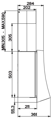
Dimensions
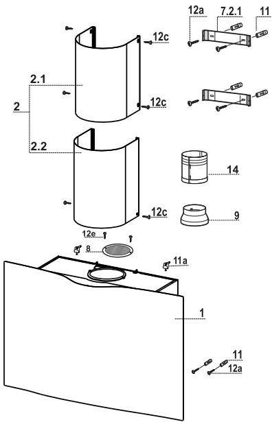
Components
| Ref. | Q.ty | Product Components |
| 1 | 1 | Hood Canopy complete with: Controls, Light, Fan unit, Filters |
| 2 | 1 | Telescopic chimney, made up of: |
| 2.1 | 1 | Upper Chimney |
| 2.2 | 1 | Lower Chimney |
| 8 | 1 | Air outlet grid D.150 |
| 9 | 1 | Damper D.150-120 |
| 14 | 1 | Hood Canopy Air Outlet Extension made up of 2 half-elements |
| Ref. | Q.ty | Installation Components |
| 11 | 6 | Wall Plugs |
| 11a | 2 | SB 12/10 Wall Plugs |
| 12a | 6 | Screws 4.2x44.4 |
| 12c | 6 | Screws 2.9x9.5 |
| 12e | 2 | Screws 2.9x6.5 |
| Q.ty | Documentation | |
| 1 | Instruction Manual | |
Drilling the Wall and Fixing the Brackets
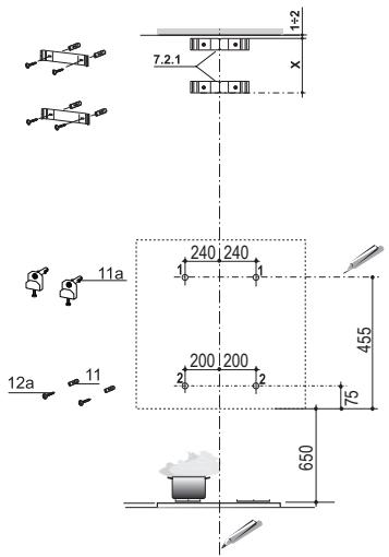
Draw the following on the Wall:
- a Vertical line up to the ceiling or top surface, at the centre of the area in which the Hood is to be fitted;
- a Horizontal line: 650 mm min. above the Hob;
- As shown in the drawing, mark a reference point 455mm above the reference horizontal line, and at a distance of 240mm to the right of the vertical reference line.
- Repeat this operation on the other side, checking to ensure it is level.
- Drill the points marked using a 12 mm drill bit.
- Insert the wall plugs with screw and bracket 11a into the holes, tighten.
- As shown in the drawing, mark a reference point 75 ~mm above the reference horizontal line, and at a distance of 200 ~mm to the right of the vertical reference line.
- Repeat this operation on the other side, checking to ensure it is level.
- Drill the points marked using a 8 mm drill bit.
- Insert the plugs 11 into the holes.
- Rest the Bracket 7.2.1 as indicated, 1-2 mm from the ceiling or surface above the hood, aligning its centre (grooves) with the vertical reference line.
• Mark the centres of the holes in the bracket. - Rest the Bracket 7.2.1 as indicated, X mm under the first bracket (X = height of the Upper chimney provided), aligning its centre (grooves) with the vertical reference line.
• Mark the centres of the holes in the bracket. - Drill the points marked using a 8 mm drill bit.
- Insert the plugs 11 into the holes.
• Fix the brackets using the screws 12a (4.2 x 44.4) provided.
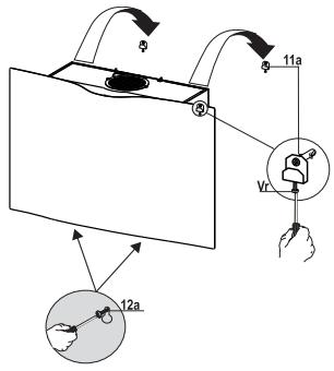
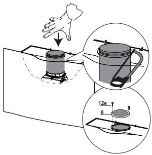
Fitting the Hood canopy
- Remove the Metal grease filter using the handles provided.
- Adjust the two screws Vr , in the brackets 11a, so that they are at the start of their travel.
- Hook the hood body to the two brackets 11a.
- From the inside of the hood body, turn screws Vr to level the hood body itself.
- Fasten the safety screws 12a.
- Replace the Metal grease filter.
Connections
AIR OUTLET - DUCTING VERSION
When installing the Ducting version, join the Hood to the outlet duct using a rigid or flexible pipe 150 - 120 selection of which is at the discretion of the installation technician.
- Check that the pipe is properly inserted onto the Motor Unit outlet.
- Fix the outlet pipe using suitable pipe clamps. The materials required to do so are not provided.
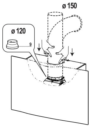
AIR OUTLET – RECIRCULATION VERSION
- Join the 2 half-elements making up the pipe 14.
- Push the pipe 14 firmly until it is all the way in.
- Cut away the excess part with a tool.
- Fix the directional Grid 8 on the recycled air outlet, using 2 screws 12e (2.9 x 9.5) provided.
- Make sure that the Activated charcoal odour filter has been fitted.
Lift the 2 tabs formed on the Hood Canopy close to the air outlet opening.
Upper chimney
- Open the two side pieces out slightly, hook them up behind the brackets 7.2.1 and bring them back together again until they are in contact.
- Fix them to the sides of the Brackets using 4 Screws 12c (2.9 x 9.5), provided.
Lower chimney
- Open out the two Chimney side flaps, hook them up between the upper chimney and the wall and then close them up again until they touch.
- Fix the lower part to the Hood canopy tabs at the sides, using 2 screws 12c (2.9 x 9.5) provided.
natural_image
Line drawing of a hand using a tool to adjust or install a circular component (no text or symbols present)
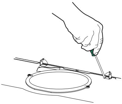
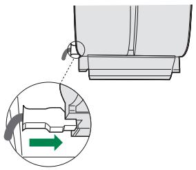
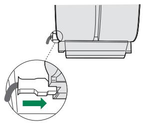
ELECTRICAL CONNECTION
- Connect the hood to the mains through a two-pole switch having a contact gap of at least 3 mm.
- Remove the grease filters (see paragraph Maintenance) being sure that the connector of the feeding cable is correctly inserted in the socket placed on the side of the fan.
natural_image
Mechanical assembly diagram showing a bracket with a green arrow indicating motion direction (no text or symbols)

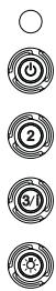
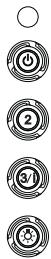
Control panel
| BUTTON | LED | FUNCTIONS |
| T1 Speed | On | Turns the Motor on at Speed one. |
| Turns the Motor off. | ||
| T2 Speed | On | Turns the Motor on at Speed two. |
| T3 Speed | Fixed | When pressed briefly, turns the Motor on at Speed three. |
| Flashing | Pressed for 2 Seconds. | |
| Activates Speed four with a timer set to 6 minutes, after which it returns to the speed that was set previously. Suitable to deal with maximum levels of cooking fumes. | ||
| L Light | Turns the Lighting System on and off. |
Warning: Button T1 turns the motor off, after first passing to speed one.
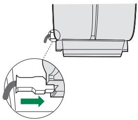
Grease filters
CLEANING METAL SELF- SUPPORTING GREASE FILTERS
- The filters must be cleaned every 2 months of operation, or more frequently for particularly heavy usage, and can be washed in a dishwasher.
- Remove the filters one at a time by pushing them towards the back of the group and pulling down at the same time.
- Wash the filters, taking care not to bend them. Allow them to dry before refitting.
- When refitting the filters, make sure that the handle is visible on the outside.
natural_image
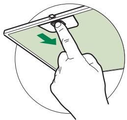
Illustration of a hand pressing a green arrow on a smartphone screen (no text or symbols)Activated charcoal filter (Recirculation version)
These filters are not washable and cannot be regenerated, and must be replaced approximately every 4 months of operation, or more frequently with heavy usage.
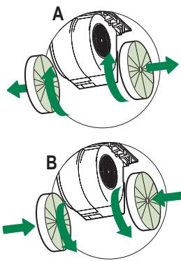
REPLACING THE ACTIVATED CHARCOAL FILTER
- Remove the metal grease filters
- Remove the saturated activated charcoal filter as shown (A).
• Fit the new filters (B). - Replace the metal grease filters.
natural_image
Diagram of two mechanical components labeled A and B with green directional arrows indicating motion or force (no text or symbols beyond labels)Lighting unit
- For replacement contact technical support ("To purchase contact technical support").

natural_image
Line drawing of a hand using a tool to draw or inspect a circular component (no text or symbols)
ELEKTROANSCHLUSS
natural_image
Mechanical component diagram showing a bracket with a green arrow indicating direction (no text or symbols present)

Schalttafel
natural_image
Illustration of a hand pressing a green arrow on a smartphone screen (no text or symbols)natural_image
Diagram of a mechanical device with green arrows indicating rotational or directional motion (no text or symbols)
natural_image
Diagram of a mechanical device with rotating wheels and green directional arrows indicating motion (no text or symbols)Beleuchtung
LED-Strahler
natural_image
Line drawing of a hand using a tool to measure a circular component (no text or symbols)
BRANCHEMENT ELECTRIQUE
natural_image
Mechanical assembly diagram showing a bracket with a green arrow indicating motion (no text or symbols present)

natural_image
Illustration of a hand pressing a green arrow on a smartphone screen (no text or symbols)Filtre anti-odeur (Version filtrante)
REPLACEMENT FILTRE AU CHARBON ACTIF
natural_image
Diagram of a mechanical device with rotating wheels and green arrows indicating motion (no text or symbols)
natural_image
Diagram of a mechanical device with rotating wheels and green directional arrows indicating motion (no text or symbols)Éclairage
natural_image
Line drawing of a hand using a tool to measure a circular component (no text or symbols)
CONEXIÓN ELÉCTRICA
natural_image
Mechanical assembly diagram showing a bracket with a green arrow indicating motion (no text or symbols present)

Tablero de mandos
natural_image
Illustration of a hand pressing a green arrow on a smartphone screen (no text or symbols)natural_image
Diagram of two mechanical components labeled A and B with green directional arrows indicating rotation or movement (no text or symbols beyond labels)Iluminación
natural_image
Line drawing of a hand using a tool to draw or inspect a circular component (no text or symbols)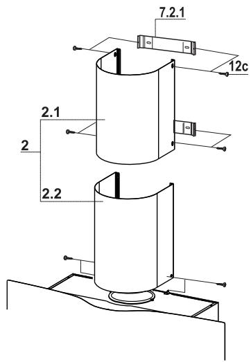
natural_image
Diagram showing a mechanical component with a green arrow indicating direction, no text or symbols present

Panel sterowania
natural_image
Illustration of a hand pressing a green arrow on a smartphone screen (no text or symbols)natural_image
Diagram of two mechanical components labeled A and B with green directional arrows indicating rotation or movement (no text or symbols beyond labels)Oświetlenie
natural_image
Line drawing of a hand using a tool to measure a circular component (no text or symbols)
natural_image
Mechanical component diagram showing a bracket with a green arrow indicating a specific part (no text or symbols present)

Панель управления
natural_image
Illustration of a hand pressing a green arrow on a smartphone screen (no text or symbols)natural_image
Diagram of two mechanical components labeled A and B with green directional arrows indicating motion or force (no text or symbols beyond labels)Освещение
natural_image
Line drawing of a hand using a tool to inspect or adjust a circular component (no text or symbols present)
ΗΛΕΚΤΡΙΚΗ ΣΥΝΔΕΣΗ
natural_image
Diagram showing a mechanical component with an inset view of a tool interacting with a green arrow (no text or symbols present)
natural_image
Illustration of a hand pressing a green arrow on a smartphone screen (no text or symbols)natural_image
Diagram of a mechanical device with rotating wheels and green arrows indicating motion (no text or symbols)
natural_image
Diagram of a mechanical or fluidic device with directional arrows indicating flow or movement (no text or symbols)Φωτισμός
natural_image
Line drawing of a hand using a tool to measure a circular component (no text or symbols)
SÄHKÖLIITÄNTÄ
natural_image
Diagram showing a mechanical component with a green arrow indicating direction, no text or symbols present

Käyttöpaneeli
natural_image
Illustration of a hand pressing a green arrow on a smartphone screen (no text or symbols)natural_image
Diagram of two mechanical components labeled A and B with green directional arrows indicating motion or force (no text or symbols beyond labels)Valaistus
natural_image
Line drawing of a hand using a tool to cut or inspecting a circular component (no text or symbols)
TILSLUTNING TIL STR∅MFORSYNING
natural_image
Mechanical component diagram showing a bracket with a green arrow indicating rotation or movement (no text or symbols present)

Betjeningspanel
natural_image
Illustration of a hand pressing a green arrow on a smartphone screen (no text or symbols)natural_image
Diagram of a mechanical device with rotating wheels and green arrows indicating motion (no text or symbols)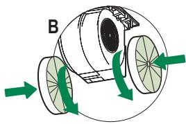
natural_image
Diagram of a mechanical or fluidic system with directional arrows indicating flow or movement (no text or symbols)Belysning
natural_image
Line drawing of a hand using a tool to cut or mark a circular component (no text or symbols)
ELEKTRISK TILKOPLING
natural_image
Mechanical assembly diagram showing a bracket with a green arrow indicating a directional change (no text or symbols present)

Kontrollpanel
| KNAPP | LED | FUNKSJONER |
| T1 Hastighet | Tent | Slår motoren på ved den første hastigheten. |
| Slår av motoren. | ||
| T2 Hastighet | Tent | Slår motoren på ved den andre hastigheten. |
| T3 Hastighet | Tent konstant | Trykk kort på knappen for å slå motoren på ved den tredje hastigheten. |
| Blinker | Trykk i 2 sekunder.Aktiverer den fjerde hastigheten i 6 minutter. Når tiden er utløpt går den automatisk tilbake til den tidligere innstilte hastigheten. Egnet til å fjerne mye os. | |
| L Lys | Tenner og slukker belysningen. |
natural_image
Illustration of a hand pressing a green arrow on a smartphone screen (no text or symbols)natural_image
Diagram of a mechanical device with rotating wheels and green arrows indicating motion (no text or symbols)
natural_image
Diagram of a mechanical or fluidic device with green arrows indicating flow direction (no text or symbols)Belysning
- Kontakt kundeservice for utbytting ("Kontakt kundeservice for kjøp").

natural_image
Line drawing of a hand using a tool to draw or inspect a circular component (no text or symbols)
ELEKTRIČNA PRIKLJUČITEV
natural_image
Mechanical component diagram showing a bracket with a green arrow indicating rotation or movement (no text or symbols present)

Nadzorna plošča
natural_image
Illustration of a hand pressing a green arrow on a smartphone screen (no text or symbols)natural_image
Diagram of a mechanical device with rotating wheels and green arrows indicating motion (no text or symbols)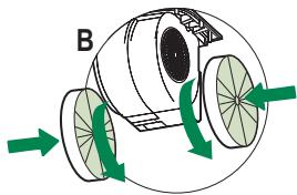
natural_image
Diagram of a mechanical or fluidic system with rotating components and directional arrows (no text or symbols)Osvetljava
natural_image
Line drawing of a hand using a tool to cut or inspecting a circular component (no text or symbols)
ELEKTRICKÉ ZAPOJENIE
- Odsávač pár zapojte k napájacej elektrickej sieti, pričom zarad'te bipolárny vypínač so vzdialenost'ou kontaktov aspoň 3 mm.
- Vyberte tukové filtre (pozrite ods.“Údržba”) a skontrolujte, či je zástrčka prívodného elektrického kábla správne zasunutá v zásuvke odsávača
natural_image
Mechanical component diagram showing a bracket with a green arrow indicating a specific part (no text or symbols present)

Ovládací panel
natural_image
Illustration of a hand pressing a green arrow on a smartphone screen (no text or symbols)natural_image
Diagram of a mechanical device with rotating wheels and green arrows indicating motion (no text or symbols)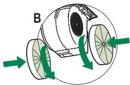
natural_image
Diagram of a mechanical or fluidic system with directional arrows indicating flow or movement (no text or symbols)Osvetlenie
natural_image
Line drawing of a hand using a tool to draw or inspect a circular component (no text or symbols)
ELEKTRIČNI SPOJ
- Spojite pokrov na napajanje mreže stavljanjem između dvopolnog prekidača s otvorom kontakata od najmanje 3 mm.
- Uklonite filtre protiv masnoće (vidi par. «Održavanje» i osigurajte da je konektor voda za napajanje pravilno uključen u kontakt usisača
natural_image
Diagram showing a mechanical component with a highlighted section and directional arrow (no text or symbols)

Kontrolna ploča
| TIPKA | LED | FUNKCIJE | |
| T1 | Brzina | Uključen | Uključuje motor na prvu brzinu. |
| Isključuje motor. | |||
| T2 | Brzina | Uključen | Uključuje motor na drugu brzinu. |
| T3 | Brzina | Neprekidno | Kad se kratko pritisne uključuje motor na treću brzinu. |
| Bljeskajuće | Pritisnuto na 2 sekunde. | ||
| Uključuje četvrtu brzinu tempiranu na 6 minuta, nakon čega se vraća na prethodno postavljenu brzinu. Prikladna za maksimalne emisije para od kuhanja. | |||
| L | Svjetlo | Uključuje i isključuje rasvjetni uređaj | |
Pažnja: Tipka T1 gasi motor prelazeći uvijek na prvu brzinu.
Filtri protiv masnoće
ČIŠĆENJE METALNIH SAMONOSIVIH FILTARA PROTIV MASNOĆE
- Mogu se prati i u perilici za posuđe, a treba ih prati otprilike nakon svaka 2 mjeseca korištenja ili češće, kod posebno intenzivnog korištenja.
- Uklonite filtre jedan po jedan, pritiskom prema stražnjem dijelu sklopa i povlačenjem istodobno prema dolje.
- Operite filtre izbjegavajući njihovo savijanje i ostavite ih da se osuše prije no što ih stavite natrag.
- Ponovno ih namjestite pazeći da ručica ostane okrenuta prema vanjskoj vidljivoj strani.

natural_image
Illustration of a hand pressing a green arrow on a smartphone screen (no text or symbols)natural_image
Diagram of a mechanical device with rotating wheels and green arrows indicating motion (no text or symbols)
natural_image
Diagram of a mechanical or fluidic device with directional arrows indicating flow or movement (no text or symbols)Rasvjeta
- Za zamjenu kontaktirajte tehničku podršku ("Za kupnju se obratite tehničkoj podršci").

natural_image
Line drawing of a hand using a tool to cut or inspecting a circular component (no text or symbols)
ELEKTRICKÉ PŘIPOJENÍ
natural_image
Mechanical component diagram showing a bracket with a green arrow indicating direction (no text or symbols present)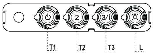

Ovládací panel
natural_image
Illustration of a hand pressing a green arrow on a smartphone screen (no text or symbols)natural_image
Diagram of a mechanical device with rotating wheels and green arrows indicating motion (no text or symbols)
natural_image
Diagram of a mechanical or fluidic device with directional arrows indicating flow or movement (no text or symbols)Světlení
natural_image
Line drawing of a hand using a tool to draw or inspect a circular component (no text or symbols)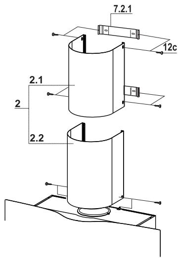
СВЪРЗВАНЕ КЪМ ЕЛЕКТРИЧЕСКАТА МРЕЖА
natural_image
Mechanical component diagram showing a bracket with a green arrow indicating rotation or movement (no text or symbols present)

Панел за управление
natural_image
Illustration of a hand pressing a green arrow on a smartphone screen (no text or symbols)natural_image
Diagram of a mechanical device with rotating components and green arrows indicating motion (no text or symbols)
natural_image
Diagram of a mechanical or fluidic device with green arrows indicating flow direction (no text or symbols)Осветителн прибор
تركيب أنوب المدخنة
natural_image
Line drawing of a hand using a tool to adjust or install a circular component (no text or symbols present)
التوصيل الكهربائي
natural_image
Diagram showing a mechanical component with a green arrow indicating direction, no text or symbols present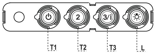
لوحة التحكم
natural_image
Illustration of a hand pressing down on a smartphone screen with a green arrow indicating the scroll (no text or symbols present)natural_image
Diagram of a mechanical device with rotating wheels and green arrows indicating motion (no text or symbols)