
LHS 225 EQ - Random Orbital Sander FESTOOL - Free user manual and instructions
Find the device manual for free LHS 225 EQ FESTOOL in PDF.

| Product type | Self-supporting eccentric sander with extension (PLANEX) |
| Brand | FESTOOL |
| Model | LHS 225 EQ |
| Rated power consumption | 550 W |
| Speed | 340 - 910 rpm (electronically adjustable) |
| Sanding pad diameter | 215 mm |
| Abrasive diameter | 225 mm |
| Tool holder | D 13/10 |
| Extraction connection | 36 mm (adaptable to 27 mm) |
| Length (short version) | 1.10 m |
| Length (long version with extension tube) | 1.60 m |
| Weight (short version) | 3.80 kg |
| Weight (long version) | 4.60 kg |
| Protection class | II (double insulation) |
| Sound pressure level | 82 dB(A) (LpA) |
| Sound power level | 93 dB(A) (LWA) |
| Vibration emission value (ah) | < 2.5 m/s² (uncertainty K=3 m/s²) |
| Abrasive attachment system | StickFix (hook and loop) |
| Electronic functions | Soft start, speed regulation, constant speed control, overload protection |
| Extraction settings | Switchable internal/external extraction; adjustable extraction power (6 levels) |
| Maintenance | Clean ventilation slots and dust filter; auto-stop carbon brushes |
| Included accessories | Extension tube, handle, sanding pad, StickFix abrasive, removable brush segment |
| Warranty | 24 months (EU) / 12 months (outside EU, legal minimum) |
Frequently Asked Questions - LHS 225 EQ FESTOOL
User questions about LHS 225 EQ FESTOOL
0 question about this device. Answer the ones you know or ask your own.
Ask a new question about this device
Download the instructions for your Random Orbital Sander in PDF format for free! Find your manual LHS 225 EQ - FESTOOL and take your electronic device back in hand. On this page are published all the documents necessary for the use of your device. LHS 225 EQ by FESTOOL.
USER MANUAL LHS 225 EQ FESTOOL
1 Symbols
2 Technical data
3 Machine features
4 Intended use
5 Safety instructions
6 Commissioning
7 Machine settings
8 Operation
9 Service and maintenance
10 Accessories
11 Disposal
12 Warranty
13 EU Declaration of Conformity
14 Troubleshooting
The specified illustrations are at the beginning of the Operating Instructions.
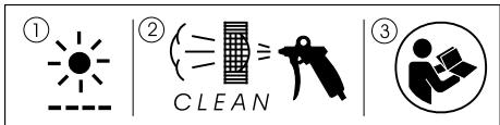
1 Symbols

Warning of general danger

Risk of electric shock

Wear a dust mask!

Wear ear protection.

Clean the air vent slits and dust filter

Read the Operating Instructions/Notes!
2 Technical data
| Power | 550 W |
| Rotational speed | 340 – 910 rpm |
| Sanding pad dia. | 215 mm |
| Abrasive dia. | 225 mm |
| Tool holder | D 13/10 |
| Dust extractor connection dia. | 36 mm |
| (27 mm) | |
| Length of short version (without extension pipe) | |
| 1.10 m | |
| Length of long version (with extension pipe) | |
| 1.60 m | |
| Weight without cable | |
| Short version | 3.80 kg |
| Long version | 4.60 kg |
| Protection class | II/回 |
3 Machine features
[1-1] Sanding head
[1-2] Extension pipe
[1-3] Handle section
[1-4] Abrasive
[1-5] Mains power cable
4 Intended use
The PLANEX is designed for sanding primed drywall constructions, ceilings and walls in internal and external applications as well as removing carpet residue, coats of paint, coverings, adhesives and loose plaster.
- When sanding large filled surfaces with high dust development, we recommend the Festool mobile dust extractor CTL/M 36 E AC PLANEX.
The user bears the responsibility for damage and accidents caused by improper use.
5 Safety instructions
5.1 General safety instructions
WARNING! Read all safety warnings and all instructions. Failure to follow the warnings and instructions may result in electric shock, fire and/or serious injury.
Save all warnings and instructions for future reference.
The term „power tool“ in the warnings refers to your mains-operated (corded) power tool or battery-operated (cordless) power tool.
5.2 Machine-related safety instructions
- This machine is designed for sanding. Please read all of the safety information, instructions, illustrations and descriptions delivered with the machine. If the following instructions are not observed, this can result in an electric shock, fire and/or serious injury.
- Do not use this machine to perform work such as roughing, brushing, polishing or disc sanding. Performing tasks for which the machine is not designed can create hazards and lead to injury.
- Never use accessories that were not specially developed and intended for this machine. Just because an accessory part can be fitted on your machine does not guarantee danger-free operation.
-
The permissible rotational speed of the accessory must be at least as high as the maximum speed specified on the machine. Accessories that rotate faster than the permissible level can rupture.
-
The outside diameter and the thickness of accessories must be within the specified size range of the machine. Accessories with incorrect dimensions cannot be sufficiently protected or controlled.
- The bore diameter of discs, flanges, support plates and all other accessories must fit the machine spindle exactly. Accessories with an unsuitable diameter are out of round, vibrate excessively and lead to loss of control.
- Do not use damaged accessories. Before use, always check accessories such as sanding pads for nicks or cracks and check support plates for cracks and excessive wear. Every time the machine is dropped, check the machine and accessories for damage, or install undamaged accessories. Following the check and assembly of accessories, ensure that all persons are beyond the rotating range of the tool and run the machine for one minute at maximum speed. Damage accessories usually break completely during this test time.
- Wear personal protective equipment. Depending on the application, use a shield or protective goggles. If practical, wear a breathing mask, ear protectors, safety gloves and a work apron suitable to protect against impact or small sanding or workpiece parts. The protective goggles must be capable of blocking flying debris caused by the various work operations. The breathing mask or device must be capable of filtering particles generated during work. Continuous exposure to loud noise can cause loss of hearing.
- Ensure that persons standing near the machine are at a safe distance from the work area. All persons in the work area must wear personal protective equipment. Parts of the workpiece or broken accessories can fly off and cause injury outside the immediate work area.
- Always hold the machine by the insulated handles if you intend to perform work that may pose a risk of cutting into hidden power cables or your own machine cable. Contact with live cables transfers an electric current to metallic machine components and causes electric shocks.
- Keep the power cable away from rotating parts. If you lose control, the power cable could be cut or become stuck and your hand or arm could be drawn into the rotating parts.
-
Never set the machine down until the tool has stopped completely. Turning tools can catch on the storage surface, causing you to lose control of the machine.
-
Never allow the machine to operate while carrying it at your side. The rotating tool can catch on your clothing by accident and cause serious cutting injuries.
- Clean the air vent slits on your machine on a regular basis. The cooling air fan sucks the dust into the machine and excessive deposits of metal dust can result in electrical hazards.
- Never operate the machine near combustible materials. Sparks can ignite these materials.
- Never use tools that have to be liquid-cooled. Water and other liquid coolants can cause potentially fatal electric shocks.
Cause and prevention of kickbacks
A kickback is a sudden reaction to jamming or catching of a rotating disc, a support plate, a brush or other accessory. Jamming or catching results in a rapid standstill of the rotating accessory, whereby, as a counter-reaction, an out-of-control machine is accelerated around the jamming point in a direction of rotation opposed to the accessory.
If, for example, a sanding disc is jammed or caught by the workpiece, the disc circumference can dig into the workpiece surface at the jamming point, causing the disc to be expelled. The disc can either fly towards or away from the user, depending on the direction of rotation of the disc at the jamming point. This can also cause sanding discs to break. A kickback is the result of misuse of the machine and/or incorrect method of work or operation and can be avoided by closely observing the following precautionary measures.
- Always hold the machine firmly and position your body and arms such that you can control any kickback force. Always use the auxiliary handle, if included in the delivery, to ensure optimum control over kickbacks or reaction torques during start-up. The user can control reaction torques or kickbacks if suitable precautionary measures are taken.
- Never place your hands near rotating tools. Tools can kick back over your hand.
- Never position your body in the area in which the machine moves in the event of a kickback. A kickback accelerates the machine in the direction of rotation opposed to the disc at the jamming point.
- Take extra care when working in corners, on sharp edges, etc. Avoid kickbacks and prevent the tool from seizing. Corners, sharp edges or a jump back tend to cause the rotating tool to catch, thus leading to a loss of control or a kickback.
Special safety instructions for fine sanding
- Do not use excessively large sanding discs when fine sanding. Observe the specifications of the manufacturer when selecting abrasive discs.
A sanding disc that is too large and protrudes over the sanding pad represents a cutting injury hazard and can cause catching, disc tears or kickbacks.
Additional warning notes
- Hold the machine firmly with both hands and assume a stable stance when performing work. Hold the machine with both hands to guide more securely.
- If potentially explosive or self-igniting dust is produced during sanding, the processing instructions of the material manufacturer must be observed under all circumstances.
- Harmful/toxic dusts can be produced during your work (e.g. lead-containing paint, some types of wood and metal). Contact with these dusts, especially inhaling them, can represent a hazard for operating personnel or persons in the vicinity. Comply with the safety regulations that apply in your country. Connect the electric power tool to a suitable extraction system. To protect your health, wear a P2 protective mask.
- Never use machines with a damaged cable. Do not touch damaged cables and pull the plug from the mains power supply if the cable becomes damaged during work. Damaged cables increase the risk of electric shock.
- Use a maximum of two extension pipes on the machine.
5.3 Emission levels
Levels determined in accordance with EN 60745 are typically:
Sound pressure level 82 dB(A)
Noise level 93 dB(A)
Measuring uncertainty allowance K = 3 dB

CAUTION
The noise produced during work may damage your hearing.
- Wear ear protection!
Overall vibration levels (vector sum for three directions) measured in accordance with EN 60745:
Vibration emission level
(3-axis)
Uncertainty
$$ a _ {h} < 2. 5 \mathrm {m} / \mathrm {s} ^ {2} $$
$$ K = 3 \mathrm {m} / \mathrm {s} ^ {2} $$
The emission values specified (vibration, noise) were measured in accordance with the test conditions stipulated in EN 60745 and are intended for machine comparisons. They are also used for making preliminary estimates regarding vibration and noise loads during operation.
The emission values specified refer to the main applications for which the power tool is used. If the electric power tool is used for other applications, with other tools or is not maintained sufficiently prior to operation, however, the vibration and noise load may be higher when the tool is used. Take into account any machine idling times and downtimes to estimate these values more accurately for a specified time period. This may significantly reduce the load during the machine operating period.
6 Commissioning

WARNING
Risk of accident if the machine is operated using unauthorised voltages or frequencies.
- The mains voltage and the frequency of the power source must correspond with the specifications on the machine's name plate.
- In North America, only Festool machines with voltage specifications of 120 ~V may be used.
The switch [5-2] is an on/off switch (I = ON, 0 = OFF). Connecting and detaching the mains power cable [1-5], see Fig. [4].
7 Machine settings

WARNING
Risk of accident, electric shock
- Always pull the plug out of the socket before performing any type of work on the machine.
7.1 Fitting the PLANEX
- Hold the sanding head [1-1] with the sanding pad facing downwards.
- If closed, release the clamping levers [2-1] and [2-2].
- Slide the extension pipe [1-2] into the opening up to the stop as illustrated in [2].
- Close the clamping levers [2-1] and [2-2].
- Slide the contact slide [3-2] into the retainer as illustrated in [3].
- Press the contact slide down until it latches into position.
- Insert the handle section [1-3] at the same time.
If you wish to use the PLANEX for sanding walls in cramped spaces, for example, reduce the length of the machine by fitting the sanding head [1-1] directly to the handle section [1-3].
- When disassembling the machine, do not forget to press the button [3-1] to release the contact slide before opening clamping levers [2-1] and [2-2].
7.2 Electronics
The machine features full-wave electronics with the following properties:
Smooth start-up
The electronically controlled smooth start-up function ensures that the machine starts up smoothly.
Speed control
You can regulate the rotational speed stepplessly between 310 and 920 rpm using the adjusting wheel [5- 1]. This enables you to optimise the cutting speed to suit the respective material.
Constant speed
The preselected motor speed remains constant through electronic control. This ensures a uniform cutting speed even when under strain.
7.3 Changing sanding pads
- Insert an Allen key (size 5) into the Allen screw [6-1] on the sanding pad.
- Hold the sanding pad securely and turn the Allen key to release.
In order to further ensure optimum axial run-out, you must first clean the bearing surface for the grinding disk on the driveshaft. - Attach the new sanding pad.
- Tighten the screw [6-1].
- Only attach specified sanding pads to the machine.
In order to guarantee optimum suction output, the sealing face between the machine and the grinding disk is ground in during the first few minutes after the disk has been changed. During this time, the r.p.m. of the machine is slightly lower and white foam particles form during the grinding process. However, they do not damage the machine.
7.4 Affixing abrasives
Compatible StickFix sanding discs are quick and easy to attach to the StickFix sanding pad. Simply press the self-adhesive sanding discs [1-4] onto the sanding pad [6-2]. The adhesive coating holds the StickFix sanding pad securely in position. Make sure
that the sanding disc holes line up with the suction holes [7-3]. Tear off the sanding disc when worn.
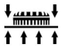
7.5 Adjusting the internal/external extraction
You can switch between internal and external extraction depending on the size of the particles produced by the sanding process.
- Push the switch [7-1] to change between the two dust extraction modes.
| Symbol | Dust extraction | Use |
| External extraction [7-2] (between sanding disc and brushing) | Extracting larger particles such as carpet residue | |
| Internal extraction [7-3] (suction hole) | Extracting small particles such as filler with maximum suction effect | |
7.6 Adjusting the suction power
You can adjust the suction power to match the surface type, but only when internal extraction is active (see chapter 7.5).
- Use the adjusting wheel [5-3] to adjust the suction power.
1: Low suction power
6: High suction power
- Start with a low suction power (position 1) and slowly increase until you can feel that the application pressure has noticeably changed.
A high suction power makes sanding work on ceilings and walls less tiring. - Excessive suction power can cause the machine to vibrate and become more difficult to guide. The machine may also be overloaded. This activates the protective circuit. The red diode flashes slowly. The electronic circuit switches to recovery speed. If this happens, you must stop working immediately until the machine has cooled down again.
7.7 Sanding close to edges
The detachable brush segment allows you to reduce the distance between the wall/ceiling and the side of the sanding pad.
- Press and hold the knob [9-1].
- Remove the brush segment [9-2].
- There is a retainer in the lid of the SYSTAINER for storing the brush segment.
- Hook in the brush segment at the opposite end to the knob [9-1], swivel towards the sanding head and engage into position.


CAUTION
Breathing in dust can damage the respiratory passage!
- Always connect the machine to a dust extractor.
- When performing work that generates dust, always wear a dust mask.
A Festool dust extractor with an extractor hose diameter of 27mm or 36mm (recommended due to the improved suction power) can be connected to the extractor connector [8-2].
The special extraction hose and special suction sleeve [8-1] (available as an accessory) ensure permanent attachment and protect against kinking.
For large surfaces, use the mobile dust extractor CTL/M 36 E AC PLANEX because it guarantees the necessary continuous suction power.
- Press the green button [8-4] to open the mechanical lock [8-3].
- Attach the extraction hose on the dust extractor to the outlet spigot [8-2].
- Swivel the mechanical lock [8-3] upwards until it engages.
Operation

WARNING
Risk of injury
- Do not hold the machine by the head.
- Hold the machine with both hands.
-
Make sure that all clamping levers are closed before operating the machine.
-
Connect the machine to the mains power supply.
Before switching on, hold the sanding head a slight distance away from the working surface. - Switch on the machine.
The on/off switch has a zero voltage actuator, which prevents the machine from starting automatically after the power supply is interrupted (e.g. after a power failure). After an interruption in voltage, press the on/off switch [5-2] to switch the machine on again. - Perform the necessary sanding work.
-
Do not overload the machine by pressing with excessive force! The best sanding results are achieved with moderate press-on pressure. The sanding performance and quality are mainly dependent on the selection of the correct abrasive.
-
Switch the machine off once the sanding task is complete.
Visual warning signals on the sanding head
The following visual signals appear on the LED [10-2] on the motor housing and the machine decreases in speed if necessary.
LED flashing slowly
The machine is overheating due to heavy dirt deposits around the air vent slits and the dust filter [10-1].
- Clean the air vent slits.
- Remove the dust filter [10-1].
- Remove the dirt deposits.
- Insert the dust filter [10-1] until it audiably engages.
The LED stops flashing once the machine is cleaned and cools down. You can then continue with your work.
If the LED is still flashing after the filter sieve and air vent slits have been cleaned:
- Apply less pressure on the surface.
- Reduce the suction output with the handwheel [5-3].
LED flashing quickly
If a malfunction occurs and the speed signal is transferred incorrectly from the handle to the motor, the motor increases to maximum speed when switched on and the LED [10-2] flashes quickly until the machine is switched off.
The machine has an internal malfunction. Have the machine inspected by an authorised service workshop.
Service and maintenance

WARNING
Risk of accident, electric shock
- Always pull the plug out of the socket before performing any type of work on the machine.
- All maintenance and repair work which requires the motor housing to be opened must only be carried out by an authorised service workshop.
-
Check the plug and the cable regularly and should either become damaged, have them replaced by an authorised after-sales service workshop.
-
To ensure constant air circulation, always keep the air vent slits in the motor housing clean and free of blockages. Read the instructions on visual warning signals in chapter 8 "Operation".
- Clean the contact slide regularly. Do not use hard objects.
The machine is equipped with self-disconnecting special carbon brushes. If they are worn, power is interrupted automatically and the machine comes to a standstill.
- Tighten the clamping levers if they no longer capable of retaining the extension pipe properly:
- Turn the screws on the clamping levers [2-1] and [2-2] approx. 1/8 of a turn.
10 Accessories, tools
Use only original Festool accessories and Festool consumable material intended for this machine because these components are designed specifically for the machine. Using accessories and consumable material from other suppliers will most likely affect the quality of your working results and limit any warranty claims. Machine wear or your own personal workload may increase depending on the application. Protect yourself and your machine, and preserve your warranty claims by always using original Festool accessories and Festool consumable material!
The order numbers of the accessories and tools can be found in the Festool catalogue or on the Internet under "www.festool.com".
11 Disposal
Do not throw the power tool in your household waste! Dispose of machines, accessories and packaging at an environmentally-responsible recycling centre. Observe the valid national regulations.
EU only: European Directive 2002/96/EC stipulate that used electric power tools must be collected separately and disposed of at an environmentally responsible recycling centre.
12 Warranty
For our tools, we give warranty for material and production defects in accordance with the locally applicable legal provisions, but in any case for at least 12 months. Within the EU member states, the warranty period is 24 months (verification through invoice or delivery note). Damage caused by, in particular, natural wear, overloading, incorrect handling, or damage caused by the operator, or
damage caused through use of the equipment contrary that specified in the Operating Instructions, or damage which was known at the time of purchase, is not covered by the warranty. Furthermore, damage caused by the use of non-original accessories and consumable materials (e.g. sanding pads) is also excluded. Complaints can only be recognised if the tool is returned while still assembled to the supplier or an authorised Festool Customer Service workshop. Keep the Operating Instructions, Safety Instructions, Spare Parts List and purchase receipt in a safe place. Otherwise the respective, current warranty conditions of the manufacturer shall apply.
Note
Due to continuous research and development work, we reserve the right to make changes to the technical content of this documentation.
13 EU Declaration of Conformity
| Long reach sander | Serial no. |
| LHS 225 EQ PLANEX | 492236, 494828 |
| Year of CE mark: 2007 | |
We declare under sole responsibility that this product complies with the following norms or normative documents: EN 60745-1, EN 60745-2-4, EN 55014-1, EN 55014-2, EN 61000-3-2, EN 61000-3-3 in accordance with the regulations stipulated in Directive 98/37/EC (until 28 Dec. 2009), 2006/42/EC (from 29 Dec. 2009), 2004/108/EC.
Head of Research, Development and Technical Documentation
Festool GmbH
Wertstraße 20
D-73240 Wendlingen
REACH for Festool products, their accessories and consumables
REACH is a European Chemical Directive that came into effect in 2007. As “downstream users” and product manufacturers, we are aware of our duty to provide our customers with information. We have set up the following website to keep you updated with all the latest news and provide you with information on all the materials used in our existing products: www.festool.com/reach
| Problem | Possible causes | Remedy |
| PLANEX bumps over the surface. | Suction power too strong | Reduce suction power or switch to external extraction if necessary. |
| Hard repair compound or hard sub-layers | Reduce suction power or switch to external extraction if necessary. | |
| Reduce speed. | ||
| Extraction power is insufficient. | Filter element on CTL/M 36 E AC PLANEX blocked / clogged. | Clean the filter element regularly: Option 1: Set the suction power control to the maximum setting. Cover the nozzle, suction hose or intake opening on the extractor with the surface of your hand for 10 seconds until the automatic cleaning cycle starts. Option 2: Clean the filter element mechanically (extracting). Option 3: Check the filter element for damage and clogging. Insert a new filter element regularly. |
| Disposal bag inserted incorrectly. | The holes punched in the disposal bag must be inside the container. | |
| Filter bag inserted instead of disposal bag. | Always work with the disposal bag when operating the PLANEX [grey bag]. | |
| Suction power setting on CTL/M 36 E AC PLANEX too low. | Adjust the suction power to a higher setting. | |
| Speed of PLANEX too fast | Reduce speed. | |
| Internal extraction on PLANEX with extraction control on setting 1 | Increase suction power or switch to external extraction. | |
| Repair compound with a high percentage of filler, soft filler | Switch on the external extractor connected to the PLANEX, set the extraction control to setting 6, in extreme cases, turn down the speed. | |
| Suction hose blocked or kinked. | Remove blockage and straighten hose. | |
| Disposal bag full | Dispose of the bag. | |
| Excessive material removed from work-piece | Speed of PLANEX too fast | Reduce speed. |
| Suction power of the PLANEX too strong | Reduce suction power or switch to external extraction. | |
| Repair compound with a high percentage of filler, soft filler | Switch on the external extractor connected to the PLANEX, set the extraction control to setting 6, in extreme cases, turn down the speed. | |
| Grit on abrasive too coarse | Select a finer grit. | |
| Surface quality not perfect | Incorrect abrasive grit | Select a finer grit. |
| Drying times of the repair compound not observed. | Read the technical data sheets and manufacturer recommendations. | |
| Suction power of PLANEX too strong | Reduce the suction power of the PLANEX | |
| Repair compound with a high percentage of filler, soft filler | Select a finer grit, e.g. P180. | |
| Machine set down on the surface while running (groove formation) | Place the machine in position and then switch on. | |
| Always use detachable brush segments when working on surfaces. | ||
| Sanding grooves on the surface | Hard sanding pad set down on the surface at an angle. | Use sanding pad IP with interface pad. |
| Sanding pad is too hard or abrasive grit too coarse for very soft repair compound. | Use sanding pad IP with interface pad. | |
| Select a finer abrasive grit (Brilliant 2 abra-sive with grit up to P 320). | ||
| PLANEX switches off during work - red LED on the head of the machine flashes | Dust filter on PLANEX clogged | Clean the dust filter on the PLANEX. |
| Excessive pressure -> machine acti-vates overheating protection | Allow the machine to cool and apply less pressure; in extreme cases, switch on the external extraction system and set the extrac-tion control to setting 6. | |
| PLANEX does not function | Electrical plug is not connected cor-rectly. | Check that the electrical plug is inserted properly. |
If other problems other than those listed occur, please contact your Festool service workshop or your local specialist dealer.
10 Accessoires, outfits
Varning for allman risk!

Varning for elstötar

OuNCTKa BeHTnJIaIauNoHHbIX npope3eN nIbJIeBbIXΦnJIbTpOB

CobIoJaTe pyKOBoDCTBO no 3KcIpyaTa- cnn/HHCTpyKcinn!

2 TexHHueckne xapaKTepncTnKn
1: HN3ka INHTeHCBHOCTb
6: BbICOKa INHTeHCNBHOCTb
- Hauchniete pa60ty, yctaHOBvH N3Kyo MoOuHocTb BCacsbBaHHa (noLoXeHne 1). 3aTeM PnaBHO yBeJIuHBaIte ee eoNoRbHeHHaBLeHHa npiJxIMa.
BbICOKa HHTeHcNBHOCTb NblYeJaIeHNr o6ecneuBaet Heo6peMeHnteJbHoe WlnΦOBAHnE CTeh I NOTOLKOB.
ClnuKOM 60JIb7a MoUHocTb BCacbIBAHnMoJxet npNBecTN K Bo3HKnHOBeHIO Bn6paun N Bbl3BaT IpO6IeMbIC ynpabLeHneM INHCTpyMeHTom.Kpome TOrO,Bo3MOxHa nepeRpy3Ka MaunHKNi, KaC cJeDCTBne, Cpa6aTbIBaHne 3auntHO BblKlOyateJ. Muraet KpacbIcBEtOnoJ. 3JIeKTPoHnka nepeKlOuaeMaunHky B pexm IOnHKeHHou JcaToTBbPaueHnry.B 3Tom clyuae npOdoJIxatb pa6Ot MyKHO ToIbKO nocJe TOrO, KaK MaunHKA ocTbIHeT.