
PSX 550 - Electric drill KRESS - Free user manual and instructions
Find the device manual for free PSX 550 KRESS in PDF.
User questions about PSX 550 KRESS
0 question about this device. Answer the ones you know or ask your own.
Ask a new question about this device
Download the instructions for your Electric drill in PDF format for free! Find your manual PSX 550 - KRESS and take your electronic device back in hand. On this page are published all the documents necessary for the use of your device. PSX 550 by KRESS.
USER MANUAL PSX 550 KRESS
Operating Instructions GB 7
Mode d'emploi F 10
The Pneumatic Drill Hammer can be used universally for impact drilling, for light chiselling work in masonry and for drilling as well as screwdriving in wood, metal and plastic.
1

Safety Instructions and Accident Prevention
Before putting the machine into operation, read through these operating instructions completely and observe the safety instructions contained therein as well as those in the enclosed booklet on general safety instructions for electro-tools.
A If the mains cable is damaged while working, pull the mains plug immediately.
Never work with a damaged mains cable.
A Wear protective glasses, hearing protection, protective gloves and sturdy shoes.
A For safety reasons, work only with the auxiliary handle 12 mounted.
A Do not work with materials containing asbestos.
A Do not carry the machine by the cable.
The mains receptacles in the working area must be protected by a residual current circuit breaker (RC).
For the attachment of identification markings on the machine, do not drill into the housing. The protective insulation would be shorted. Use stickers.
When the drill unexpectedly jams, the machine kicks back. Therefore, always take a secure stance and hold the machine firmly with both hands.
2 Illustration
1 Tool holder
2 Dust protection cap
3 Unlocking collar
4 Gear selector/Rotation stop switch
5 Locking button for on/off switch
6 On/Off switch/Speed control
7 Ventilation slots
8 Latch for mains cable module
9 Rotational direction switch
10 Drilling/Impact drilling selector
11 Holder for depth stop
12 Auxiliary handle
13 Adapter for screwdriver bits/drill chuck
Accessories illustrated or described are not always included as standard delivery items.
3 Technical Data
| Pneumatic Drill Hammer | PSE 500 | PSX 550 |
| Article number | 0428 2601 | 0428 2701 |
| Input power | 500 W | 550 W |
| Output power | 200 W | 250 W |
| Electronic speed control | ● | ● |
| No-load speed | ||
| 1st Gear | 0-950 RPM | 0-950 RPM |
| 2nd Gear | --- | 0-2000 RPM |
| Speed under load | ||
| 1st Gear max. | 0-730 RPM | 0-680 RPM |
| 2nd Gear max. | --- | 0-1540 RPM |
| No-load impact rate | 4700 per min. max. | 4700 per min. max. |
| Impact energy | 2.1 J | 2.1 J |
| Right/Left rotation | ● | ● |
| Clamping collar dia. | 43 mm Euro standard SDS-Plus | 43 mm Euro standard SDS-Plus |
| Tool holder | ||
| Drill dia., max. | ||
| Steel | 13 mm | 13 mm |
| Light metal | 15 mm | 18 mm |
| Wood | 30 mm | 35 mm |
| Hammer drilling in concrete | 20 mm | 22 mm |
| Recommended hammer drilling range | 4-12 mm | 4-14 mm |
| Screw dia., max. | ||
| Wood | 6 mm | 8 mm |
| Sheet metal | 6.3 mm | 6.3 mm |
| Weight | 2.75 kg | 2.78 kg |
| Protection class | II/回 | II/回 |
4 Noise/vibration information
Measured values determined according to EN 50 144.
Sound pressure level: 84 dB (A)
Sound power level: 97 dB (A)
Workplace related emission value: 87 dB (A).
For operation, noise protection measures are required.
The weighted acceleration is typically 8.6m / s^2


8 English
PSE 500, PSX 550
5
Mounting the Auxiliary Handle and the Mains Cable Module
Before any work on the machine itself, pull the mains plug!
Operate the machine only with the auxiliary handle 12. Place the auxiliary handle on the clamping collar and tighten with the clamping screw.
Connect the mains cable module to the handle. The plug must latch.
A Use the mains cable module provided only for Kress Electro-Tools. Do not attempt to operate other machines with the module.
Use only an original Kress mains cable module that is at least of heavy rubber sheathed cable (Code designation H07 RN-F).
6 Putting into Operation
A Check before putting into operation that the mains voltage agrees with the voltage specified on the nameplate of the machine.
SWITCHING ON/OFF
Press or release the on/off switch 6.
The on/off switch can be locked on with the locking button 5. To release, briefly press and release the on/off switch 6.
MECHANICAL GEAR SELECTION
With the gear selector/rotation stop switch 4, one of three positions can be selected.
1 = Lower speed range: Hammer drilling, drilling with normal twist drills in wood/metal over 8 mm dia. and mixing work.
2 = Higher speed range: Drilling with normal twist drills to 8 mm dia.
No rotation: Light chiselling work.
The switch-over can best be performed at a standstill. Please observe that the gear selector/rotation stop switch 4 can be switched only one step at a time. Only after the on/off switch 6 is actuated and the machine starts does the gear box shift to the selected mode. The gear selector/rotation stop switch 4 can only then be switched again to the next position.
DRILLING - IMPACT DRILLING
For drilling, place the selector 10 in the position.
For impact drilling, set to
The switch-over can best be performed at a standstill. Only after the on/off switch 6 is actuated and the machine starts does the gear box shift to the selected mode.
Note: Left rotation when impact drilling damages the drill. Switch off the impact mechanism for diamond crown drilling or for mixing work.
For chiselling work, set the selector 4 to the = position.
When hammer drilling, use exclusively drills with hard metal inserts and SDS-Plus shafts. The use of commercially available masonry drills with cylindrical shafts by means of the adapter 13 and the normal drill chuck in conjunction with the pneumatic impact mechanism is not possible.
SPEED CONTROL

With the on/off switch 6, the speed can be continuously varied. With light pressure on the on/off switch 6, the machine begins to rotate slowly; with increased pressure, the speed increases.
ROTATIONAL DIRECTION SWITCHING

Operate the rotational direction switch 9 only when the machine is at a standstill!
Take hold of the rotational direction switch 9 on both sides.
Right rotation:
Set the rotational direction switch 9 to "R".
Left rotation:
Set the rotational direction switch 9 to "L".
Important!
Press the rotational direction switch 9 in each case to the stop on the housing, i. e. until it can be felt to engage.
If the rotational direction switch 9 is set between the positions "R" and "L", the machine cannot be switched on.
7 Inserting/Removing Tools
The tool holder 1 clamps drilling and chiselling tools without a tool key.
INSERTING TOOLS

Before any work on the machine itself, pull the mains plug!
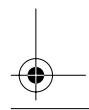
Clean and lightly grease the tool shaft.
PSE 500, PSX 550
English
9
Pull back the unlocking collar 3. Insert the tool while turning into the tool holder until it latches. Release the unlocking collar. Check whether the tool is firmly seated.
Take care that the dust protection cap 2 is not damaged.
Replace damaged dust protection caps!
REMOVING TOOLS
Slide the unlocking collar 3 to the rear and pull out the tool.
ADJUSTING THE CHISEL
Set the gear selector/rotation stop switch 4 to an intermediate position. The chisel can now be turned by hand to the required working position.
Return the gear selector/rotation stop switch 4 to the initial position. The chisel latches automatically as soon as it is radially loaded by the working or chiselling process.
8 Drill Chuck (Accessory)
For drilling work in metal, wood and plastic with drills that have normal shafts, a drill chuck (13 mm max. chuck opening) is available. The drill chuck is mounted on the adapter (accessory) for screwdriver bits. All common drill chucks with 1/2'' x 20 UNF internal threads (13 mm max. chuck opening) can be used.
MOUNTING THE CHUCK
Before any work on the machine itself, pull the mains plug!
Clean the threads of the drill chuck (accessory) and the adapter 13 (accessory).
Screw the drill chuck onto the adapter and lock the adapter in the same manner as a drill in the tool holder. To tighten the drill chuck, set the gear selector/rotation stop switch 4 temporarily to position =
9 Practical Tips
Do not drill into hidden electrical lines or gas and water pipes. Check the area to be worked with a metal detector, for example, before starting.
For metal, use only flawless, sharpened drills; for stone and concrete, only masonry drills with hard metal inserts.
Always adapt the speed to the material to be worked and the diameter of the drill. For precision working with metal and wood, place the machine in a drill stand (accessory).

IMPACT DRILLING - CHISELING Wear protective glasses and hearing protection.
Do not apply to much pressure. The performance is not increased in this manner.
The most effective method for chiselling is to break out only small pieces of material.
When chiselling, work only with protective glasses and the auxiliary handle 12. Check before starting to work if the gear selector/rotation stop switch 4 is engaged in the = position.
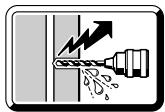
DRILLING IN TILES
Start drilling slowly on the tile. After the tile is drilled through, switch to impact drilling.
SCREWDRIVING
Screwdriver bits can be inserted into the adapter 13 (accessory). Commercially available bits with a hexagonal dimension of 6.3mm or 1/4 (DIN 3126, Form C) can be used.
The screwdriver bits are held in the adapter with a spring ring. Therefore, use only bits with a notch.
10 Maintenance Measures
Before any work on the machine itself, pull the mains plug!
Always keep the ventilation slots clean.
Wipe off the accessible plastic parts regularly with a cloth without cleaning agent.
After heavy use over a long period, the machine should be taken to a Kress service location for an inspection and thorough cleaning.
11 Environmental Protection

Kress takes back worn-out machines for the purpose of resource-saving recycling. As a result of their modular construction, Kress machines can be very easily dismantled into their reusable materials.
Give your worn-out Kress machine to your dealer or send it directly to Kress.
Subject to change without notice


10 Français
PSE 500, PSX 550
Utilisation
PERCAGE - PERCAGE AVEC PERCUSSION
TRAVAUX DE PERFORATION, DE BURINAGE
-
Marcia mass.
-
Marcia mass.
TALADRAR - TALADRAR CON PERCUTOR
OMKOPPLING AV ROTATIONSRIKTNING

Reservation for andringar


PSE 500, PSX 550
Dansk
27
Anvendelse
PORAAMINEN LAATTOIHIN
GB Declaration of conformity
We declare under our sole responsibility that this product is in conformity with the following standards or standardization documents: EN 50 144, HD 400, EN 55 014-1, EN 55 014-2, EN 61 000-2-3, EN 61 000-3-3 according to the provisions of the regulations 73/23/EEC, 89/336/EEC, 98/37/EC.
- This electro-tool was manufactured with high precision and subjected to rigorous factory quality controls.
- Therefore, we guarantee the cost-free correction of fabrication or material defects that occur within 24 months of the date of purchase by the end user. We reserve the right to repair defective parts or replace them with new parts. Replaced parts become our property.
- Improper use or handling as well as opening of the machine by unauthorised repair agencies voids the guarantee. Parts subject to wear are excluded from the guarantee.
- The guarantee may only be enforced when defects are reported without undue delay (including shipping damage). Guarantee implementation does not extend the guarantee period.
- If the tool is defective, please complete the guarantee card and return the unit, guarantee card and a brief description of the problem to the responsible service location. Please enclose your sales receipt.
- The guarantee obligations assumed by us shall exclude any further claims on the part of the buyer, in particular the right to recission of a sale, reduction and the assertion of damage claims.
- However, the buyer shall have the right to either a reduction (in the purchase price) or the recession of the sale (cancellation of the sales agreement) should we fail to eliminate any defects within a reasonable period of time.
- Damage claims in accordance with §§ 463, 480 Paragraph 2,635 BGB due to absence of guaranteed quality shall not be not excluded.
- The provisions defined in Items 7 and 8 only apply to the Federal Republic of Germany.
NL Garantie
Please fill in immediately and keep in safe place.