
HT-HECTOR-1200A - Washing machine Hillvert - Free user manual and instructions
Find the device manual for free HT-HECTOR-1200A Hillvert in PDF.


User questions about HT-HECTOR-1200A Hillvert
0 question about this device. Answer the ones you know or ask your own.
Ask a new question about this device
Download the instructions for your Washing machine in PDF format for free! Find your manual HT-HECTOR-1200A - Hillvert and take your electronic device back in hand. On this page are published all the documents necessary for the use of your device. HT-HECTOR-1200A by Hillvert.
USER MANUAL HT-HECTOR-1200A Hillvert
HT-HECTOR-1200A HT-HECTOR-1200B HT-HECTOR-1200C HT-HECTOR-1000
WOOD CHIPPER
BEDIENUNGSANLEITUNG
USER MANUAL
INSTRUKCJA OBSŁUGI
NÁVOD K POUŽITÍ
MANUEL D'UTILISATION
ISTRUZIONI PER L'USO
A - Schalldämpfer



2) Vordere Stütze

P - Drosselklappenhebel
I - Starterseil

HT-HECTOR-1200B | HT-HECTOR-1200C

This User Manual has been translated for your convenience using machine translation. Reasonable efforts have been made to provide an accurate translation; however, no automated translation is perfect nor is it intended to replace human translators. The official User Manual is the English version. Any discrepancies or differences created in the translation are not binding and have no legal effect for compliance or enforcement purposes. If any questions arise related to the accuracy of the information contained in the User Manual, please refer to the English version of those contents which is the official version.
Technical data
| Parameter description | Parameter value | |||
| Product name | Wood chipper | |||
| Model | HT-HECTOR-1200A | HT-HECTOR-1200B | HT-HECTOR-1200C | HT-HECTOR-1000 |
| Engine power [kW] | 9 | 9 | 9 | 4.1 |
| Motor speed [rpm] | 3600 | 3600 | 3600 | 3600 |
| Max. shredding diameter [mm] | 120 | 120 | 120 | 100 |
| Engine capacity [cm3] | 420 | 420 | 420 | 212 |
| Fuel consumption [g/kWh] | 374 | 374 | 374 | 395 |
| Oil tank capacity [l] | 1.1 | 1.1 | 1.1 | 0.55 |
| Fuel tank capacity [l] | 6.5 | 6.5 | 6.5 | 3.6 |
| Start | Manual | Manual | Manual | Manual |
| Dimensions [cm] | 243 x 98 x 196 | - | 250 x 85 x 128 | 137 x 53 x 114 |
| Weight [kg] | 242 | 177 | 177 | 97 |
1. Overall description
The user manual is designed to assist in the safe and trouble-free use of the device. The product is designed and manufactured in accordance with strict technical guidelines, using state-of-the-art technologies and components. Additionally, it is produced in compliance with the most stringent quality standards.
BEFORE STARTING WORK, PLEASE READ AND UNDERSTAND THIS INSTRUCTION CAREFULLY.
To increase the product life of the device and to ensure trouble-free operation, use it in accordance with this user manual and regularly perform maintenance tasks. The technical data and specifications in this user manual are up to date. The manufacturer reserves the right to make changes associated with quality improvement. The device is designed to reduce noise emission risks to a minimum, taking into account technological progress and noise reduction opportunities.
Explanation of symbols

The product meets the requirements of relevant safety standards.

Please read the instructions before use.
Recyclable product.

ATTENTION! or WARNING! or REMEMBER! A general warning sign describing a given situation.
Wear hearing protection. Exposure to noise may cause hearing loss.
Use protective gloves.
Use head protection.
Use foot protection.
Use face protection.
Use an adjustable cover.
Use a cover.
Wear protective suit.
ATTENTION! Warning against electric shock!
ATTENTION! Warning against strong noise!
ATTENTION! Swirling elements!
ATTENTION! Fire hazard – flammable materials!
Warning against the risk of poisoning by toxic substances!
Emergency stop!
Attention! Hot surface may cause burns!
ATTENTION: Keep a safe distance from nearby bystanders or animals (at least 10 m).
ATTENTION: There is a risk of foreign objects being thrown through the device!
ATTENTION! Sharp elements. Danger of limb amputation.
Keep hands or any part of the body away from the hopper, hopper and discharge chute when the machine is in use.
Always stay away from the discharge area when the machine is operating. No smoking


Smoking is prohibited near the device. The device contains flammable substances.
Protect from rain.
Before performing any maintenance on the device, ALWAYS turn off the engine first.

ATTENTION! The illustrations in this user manual are for illustration purposes only and may differ in some details from the actual appearance of the product.
2. Safety of use a

ATTENTION!
Read all safety warnings and all instructions. Failure to follow warnings and instructions could result in serious injury or death.
The terms "device" or "product" are used in the warnings and instructions to refer to: Wood chipper
2.1. Safety in the workplace
a) Make sure the workplace is clean and well lit. A messy or poorly lit workplace may lead to accidents. Try to think ahead, observe what is going on and use common sense when working with the device.
b) Do not use the device in a potentially explosive environment, for example in the presence of flammable liquids, gases or dust. The device generates sparks which may ignite dust or fumes.
c) If you discover damage or irregular operation, immediately switch the device off and report it to a supervisor without delay.
d) Only the manufacturer's service centre may make repairs to the product. Do not attempt to make repairs yourself!
e) In case of fire, use a powder or carbon dioxide (CO2) fire extinguisher (one intended for use on live electrical devices) to put it out.
f) Children or unauthorised persons are forbidden to enter a work station. (A distraction may result in loss of control over the device).
g) Use the device in a well-ventilated space.
h) The device produces dust and debris during operation. It is important to protect bystanders from their harmful effects.
i) Use the EMERGENCY STOP if there is a risk of injury or death, accident or damage.
j) Regularly inspect the condition of the safety labels. If the labels are illegible, they must be replaced.
k) Please keep this manual available for future reference. If this device is passed on to a third party, the manual must be passed on with it.
I) Keep packaging elements and small assembly parts in a place not available to children.
m) Keep the device away from children and animals.
n) If this device is used together with another equipment, the remaining instructions for use shall also be followed.
o) Make sure that the workspace is open.

Remember! Protect children and other bystanders when operating the device.
2.2. Personal security
a) Do not use the device when tired, ill or under the influence of alcohol, narcotics or medication which can significantly impair the ability to operate the device.
b) The machine may be operated by physically fit persons who are able to handle the machine, are properly trained, who have reviewed this operating manual and have received training in occupational health and safety.
c) When working with the device, use common sense and stay alert. Temporary loss of concentration while using the device may lead to serious injuries.
d) Use personal protective equipment as required for working with the device, specified in section 1 (Legend). The use of correct and approved personal protective equipment reduces the risk of injury.
e) Do not overestimate your abilities. When using the device, keep your balance and remain stable at all times. This will ensure better control over the device in unexpected situations.
f) Do not wear loose clothing or jewellery. Keep hair, clothes and gloves away from moving parts. Loose clothing, jewellery or long hair may get caught in moving parts.
g) Remove all adjusting tools or spanners before turning the device on. A tool or spanner left in the revolving part of the device may cause injury.
h) Use eye, ear and respiratory protection.
i) The device is not a toy. Children must be supervised to ensure that they do not play with the device.
j) Do not put your hands or other body parts inside the device while it is in use!
2.3. Safe use of the device
a) Do not overload the device. Use the appropriate tools for the given task. A correctly-selected device will perform the task for which it was designed better and in a safer manner.
b) Do not use the device if the ON/OFF switch does not function properly (does not switch the device on and off). Devices which cannot be switched on and off using the ON/OFF switch are hazardous, should not be operated and must be repaired.
c) When not in use, store in a safe place, away from children and people not familiar with the device who have not read the user manual. The device may pose a hazard in the hands of inexperienced users.
d) Keep the device in perfect technical condition. Before each use check for general damage and especially check for cracked parts or elements and for any other conditions which may impact the safe operation of the device. If damage is discovered, hand over the device for repair before use.
e) Keep the device out of the reach of children.
f) Device repair or maintenance should be carried out by qualified persons, only using original spare parts. This will ensure safe use.
g) To ensure the operational integrity of the device, do not remove factory-fitted guards and do not loosen any screws.
h) When transporting and handling the device between the warehouse and the destination, observe the occupational health and safety principles for manual transport operations which apply in the country where the device will be used.
i) Avoid situations where the device stops working during use due to excessive loading. This may result in overheating of the drive elements and damage to the device.
j) Do not touch articulated parts or accessories unless the device has been disconnected from the power source.
k) Do not move, adjust or rotate the device in the course of work.
I) Do not leave this appliance unattended while it is in use.
m) Clean the device regularly to prevent stubborn grime from accumulating.
n) The specified vibrations emission was measured using standard measurement methods. Vibrations emissions may change if the device is used in different surroundings.
o) Do not work on two workpieces at the same time.
p) Do not cover the air intake and outlet.
q) Do not run the device when empty.
r) It is forbidden to interfere with the structure of the device in order to change its parameters or construction.
s) Keep the device away from sources of fire and heat.
t) Do not cover the ventilation openings!
u) Keep the device away from excessive moisture or rain.
v) Do not install, remove, adjust or service the discharge screen of any other parts while the engine is running.
w) When the engine is running, keep all body parts and heavy objects away from the loading hopper and the outlet chute.
x) Do not feed cloth, stones, metal, glass, rubber, plastic, bricks, string, roots, bedding plants, bottles, cans or any other non-botanical objects into the machine.
y) Rotating cutting blades inside these openings will cause serious personal injury if touched.
z) Be careful while working. The machine can eject fragments of processed material from the loading hopper or outlet chute.
aa) The engine gets very hot during operation. Do not touch the hot engine because it may cause burns.
bb) In order to avoid fire hazard, keep leaves, grass and other combustible materials away from the hot engine and muffler.
cc) Do not operate on pavement, gravel or other hard surfaces since objects might ricochet and cause injury.
dd) Some tree species may cause an allergic reaction. Dust coming out during branch processing may be irritating or harmful, appropriate protective measures should be taken.
ee) Do not operate on uneven ground or in case the unit is unstable.
ff) If the chipped shredder jams or becomes clogged, shut off the engine immediately and wait for all moving parts to stop completely before clearing.
gg) Do not insert branches/wood larger than those specified in the technical data into the machine.
hh) Check level and if needed add engine oil till the full marking before start using the device. Working with too low oil can cause overheating or even damage the engine!
ii) Oil leaking from the machine should be reported to the appropriate services or comply with legal requirements applicable in the area of use.
jj) Poisonous carbon monoxide is present in the engine exhaust. Remaining in a carbon monoxide environment may lead to losing consciousness or even death. Do not run the engine in a closed or poor ventilated space.
kk) Protect the engine from heat, sparks and flame. Do not smoke in the vicinity of the chipper!
II) Petrol is flammable and explosive. Before refuelling the engine should be turned off and cooled down.
mm) Warning! Risk of engine damage due to wrong fuel.
nn) The battery (if there is one provided) is live. Do not touch or cross the terminals and battery connectors. Disconnecting the battery connectors should be carried out in the correct order.
oo) The device is not approved for use on roads in public traffic.
pp) Before transporting or storage let the engine cool off at least 30 min. Placing the machine in a cooler, shaded area will help to cool it down faster.

ATTENTION! Even though the device has been designed to be safe, has appropriate protective measures, and despite the use of additional user safety features, there is still a small risk of accident or injury while working with the device. It is recommended to exercise caution and common sense when using it.
3. The scope of application of the device
The device is intended for shredding branches, bushes, weeds, shoots and long, dry grass with a diameter not exceeding the value given in the technical data table. Do not use the appliance to chop construction debris, plastic, paper products, rope or string, or any material that may contain metal or large amounts of moisture/juice.
NOTE: Remove any nails, ropes, strings or stones that may be embedded in plant parts (e.g. roots, etc.) before introducing material into the device.
The user is responsible for any damage resulting from improper use.
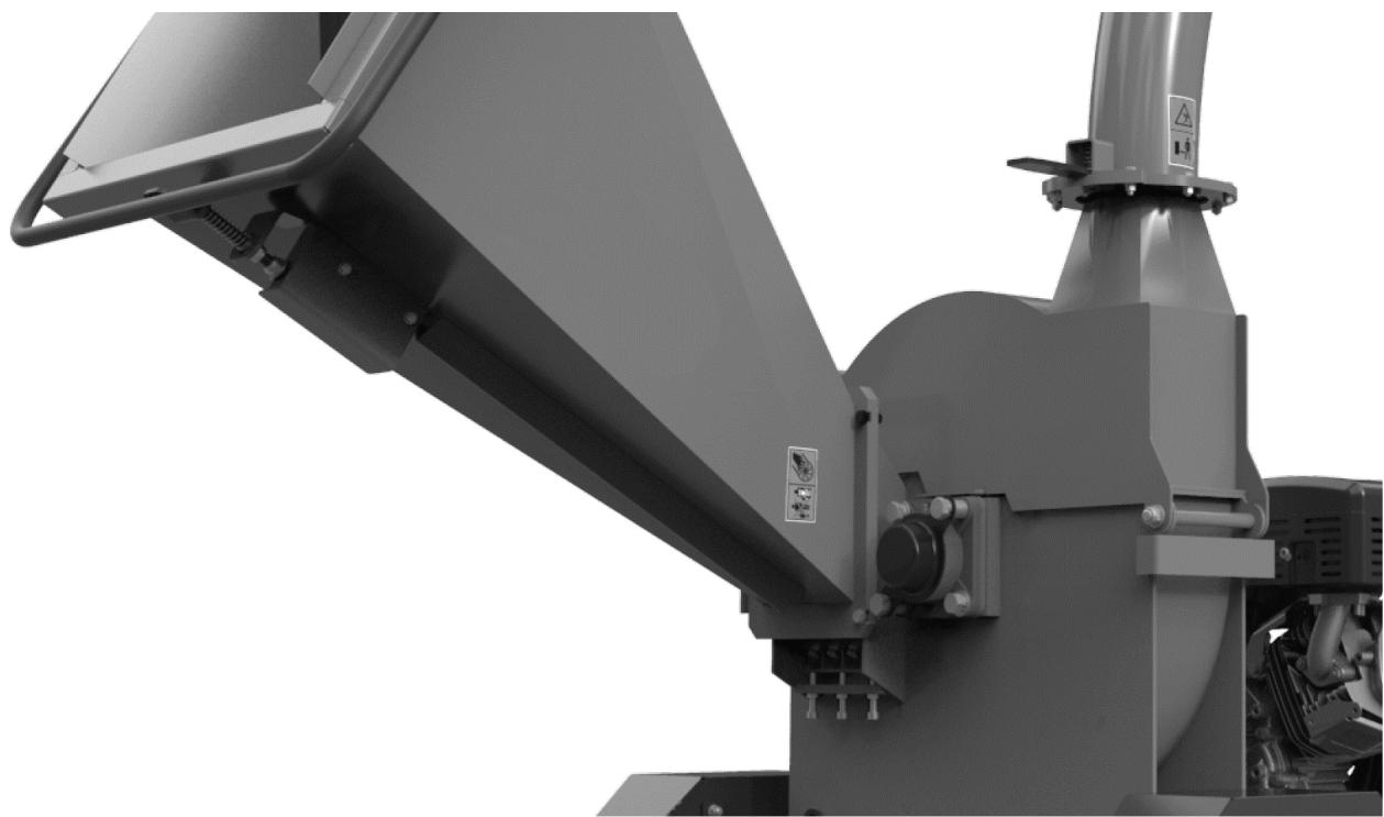
4. Device description
HT-HECTOR-1200A
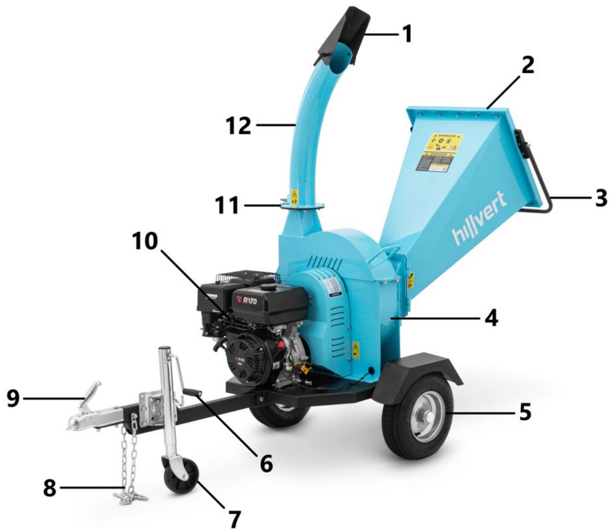
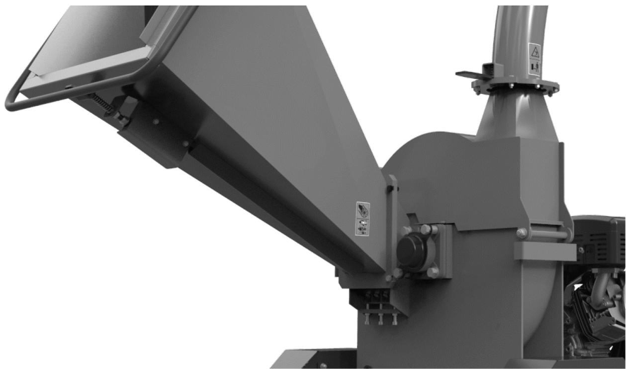
1 - Outlet cover
2 - Inlet gutter
3 - Handle
4 - Shredding drum
5 - Rear wheels
6 - Front wheel extension adjustment crank
7 - Front wheel
8 - Safety chain
9 - Tow hitch lock
10 - Engine
11 - Connecting collar
12 - Outlet chute
HT-HECTOR-1200B

1 - Outlet cover
2 - Outlet chute
3 - Engine
4 - Emergency switch
5 - Inlet gutter
6 - Wheels
7 - Support
8 - Safety chain
9 - Tow hitch lock
10 - Connecting collar
HT-HECTOR-1200C

1 - Outlet cover
2 - Outlet chute
3 - Connecting collar
4 - Engine
5 - Emergency switch
6 - Inlet gutter
7 - Extension of the inlet chute
8 - Wheels
9 - Support
10 - Safety chain
11 - Tow hitch lock
HT-HECTOR-1000

1 - Inlet gutter
2 - Emergency switch
3 - Engine
4 - Outlet chute
5 - Outlet chute cover
6 - Drive belt cover
7 - Support
8 - Wheels
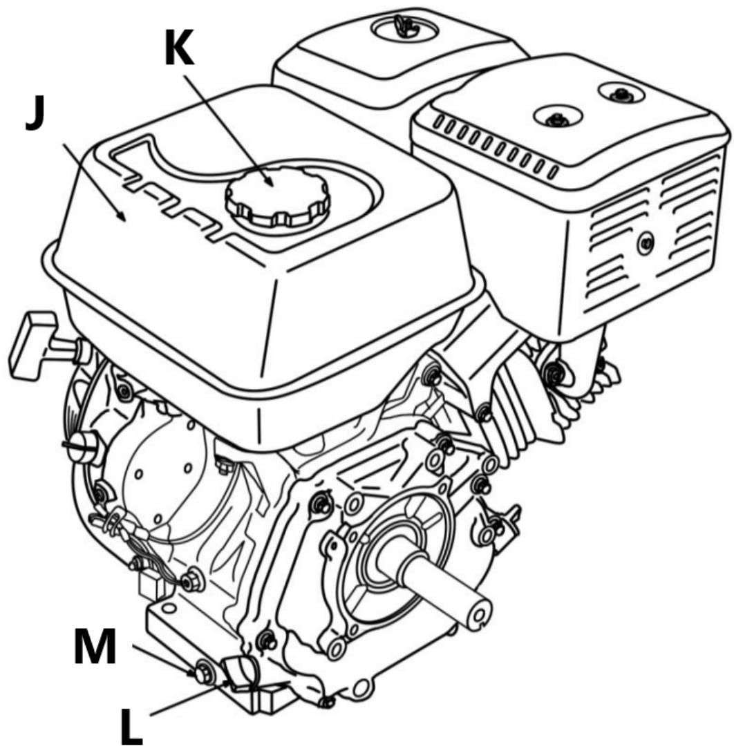
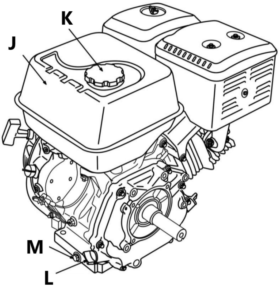
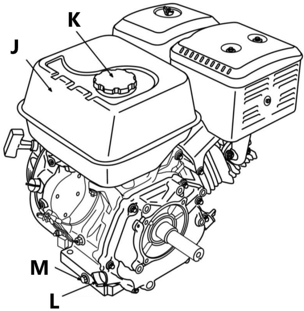
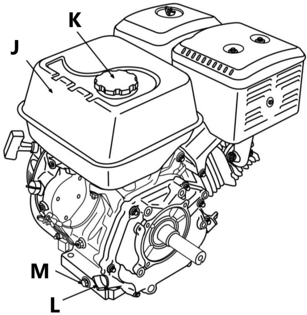
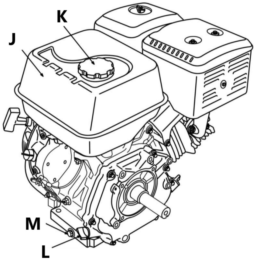
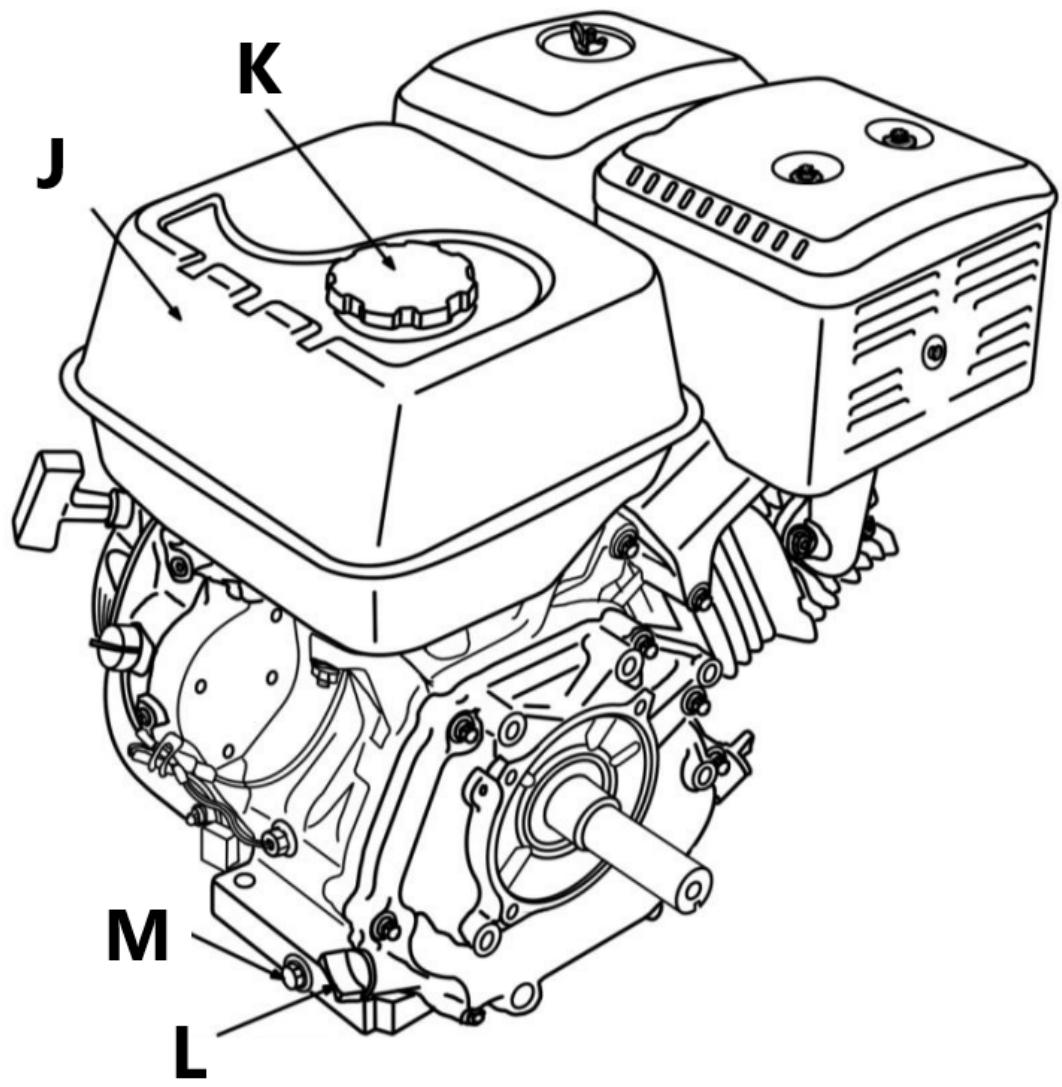
5. Engine description

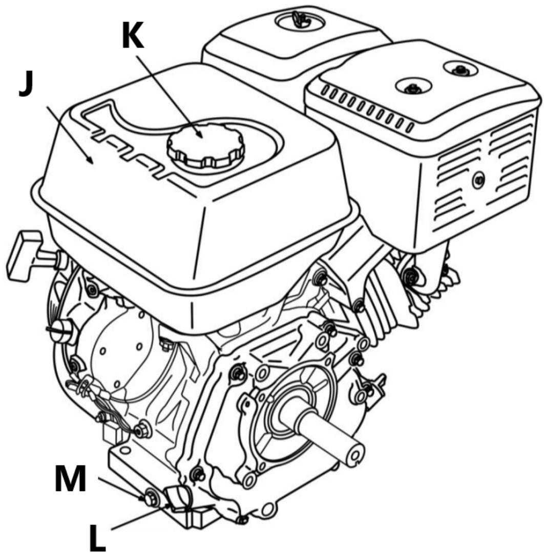
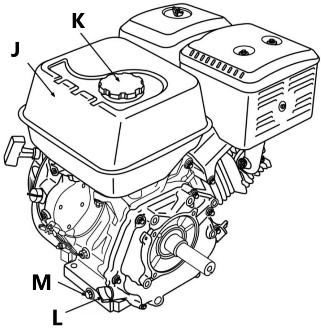
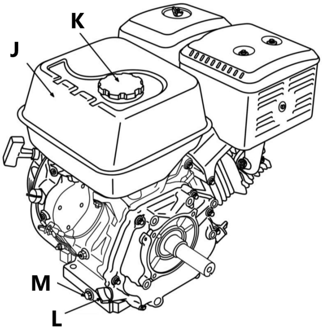
A - silencer
B - throttle lever
C - ignition on/off switch
D - starter handle
E - recoil starter
F - choke lever
G - fuel valve lever
H - air filter
I - Spark plug
J - fuel tank
K - the fuel filler cap
L - oil drain plug
M - filler cap/oil level indicator
6. Preparation to work
Device location
The device should be used outside closed rooms on a stable, horizontal and even surface, preferably on grass or ground. Do not place the machine on concrete, asphalt or other hard surfaces, because chips and other residues thrown by the machine may bounce off them and pose a hazard.
Working conditions
Inspect the material to be shredded and make sure there is enough space above the device to load the material. It is recommended to choose a workplace as close as possible to the place where the chips will be used. This will reduce the need to carry the processed material to a minimum. Maintain a safe distance from the chip ejection area. Make sure that all bystanders, children, animals or valuable items are also kept a safe distance from the chip ejection area.
Operator zone
- Operate the chipper only from the operator area.
• Find out how to tune your device. - Never move the chipper or leave it unattended while the engine is running.
- Follow the engine manual for engine maintenance and repairs

1 - Front support
2 - Operator zone
3 - Material entry zone
4 - Operator zone
5 - Engine
DANGER : This equipment is equipped with an internal combustion engine and should not be used in or near uncultivated areas of woods, brush or grass unless the engine exhaust system is equipped with a spark arrester that complies with local regulations.
7. Installation of devices
Installation of the HT-HECTOR-1200A model
Unpacking
Place the shipping box on a solid, flat surface and carefully remove the cover. Using two people, remove all parts from the box and before beginning to assemble the chipper, check whether any elements are missing.
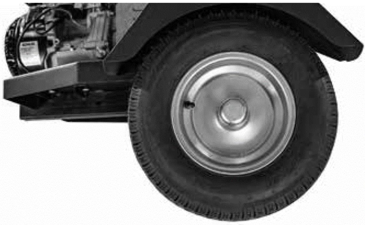
1) Fitting the wheels
a) Attach the wheel axle (2) to the chassis (1) with an M12x30 hex bolt (60), a 12 flat washer (53) and an M12 locknut (54).
b) Attach the fender (43) to the chassis (1) with an M8x20 hex bolt (63), an 8 flat washer (64) and an M8 lock nut (65).
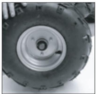
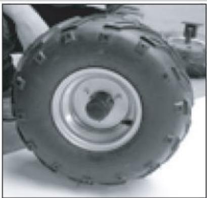
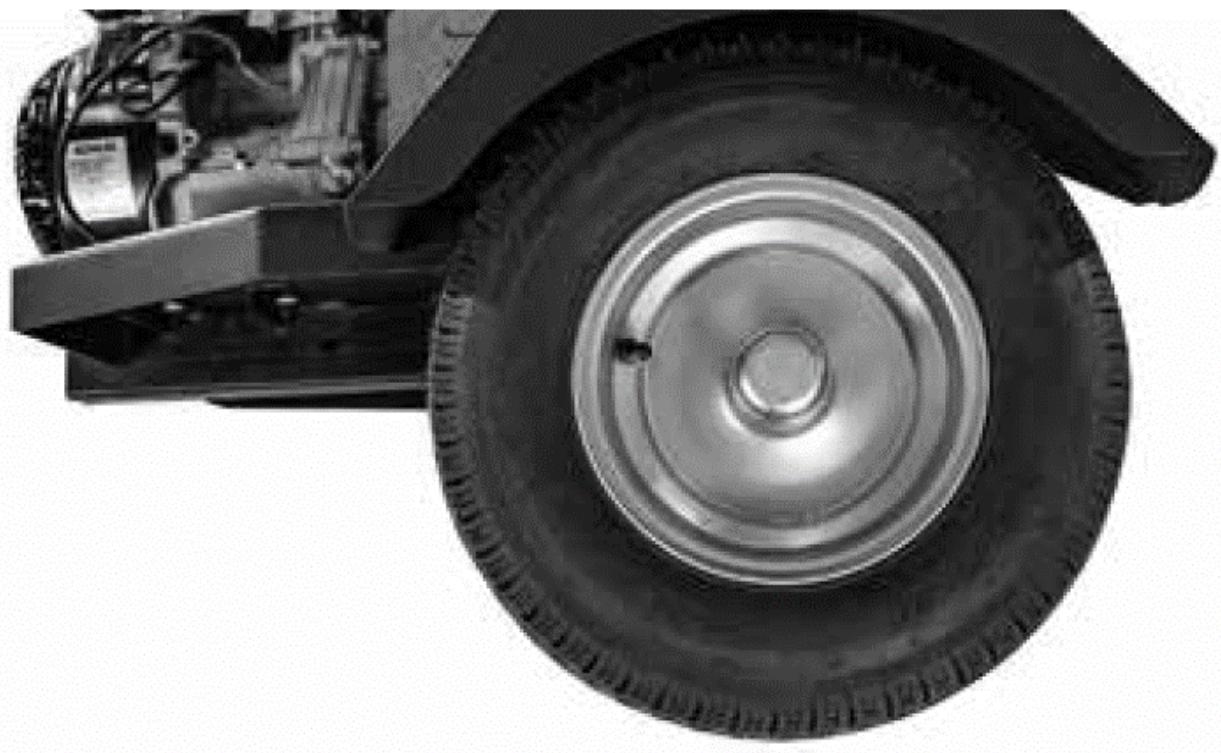
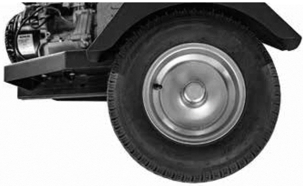
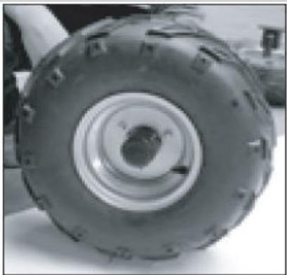
c) Attach the wheel (3) to the wheel axle (2), lock the M24x1.5 hex nut (56) with the 4x45 cotter pin (55) and install the dust cover (4) on the end with a rubber hammer.


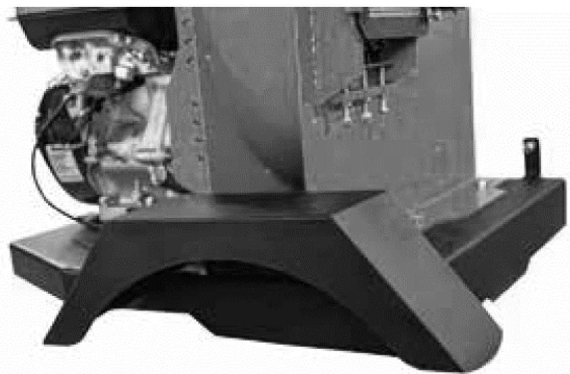
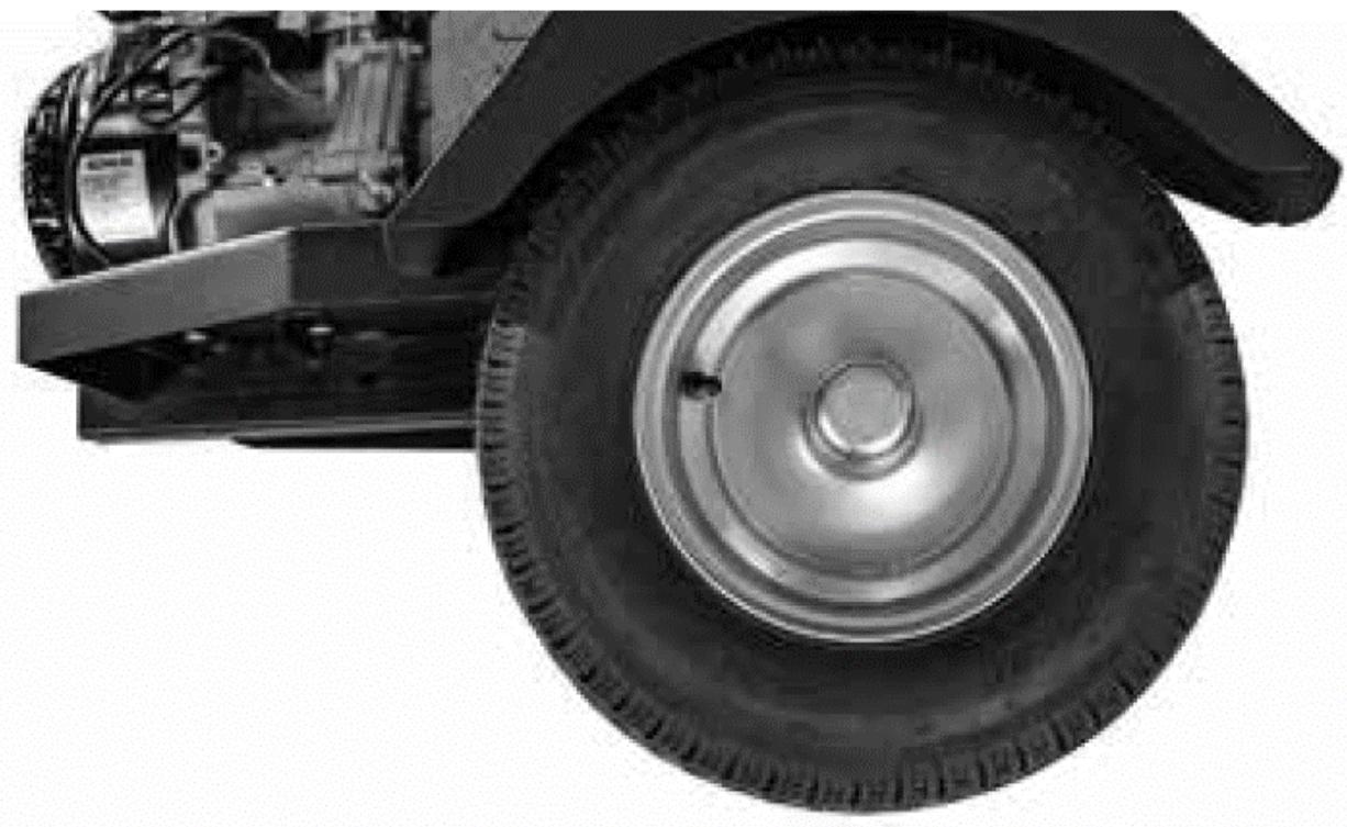
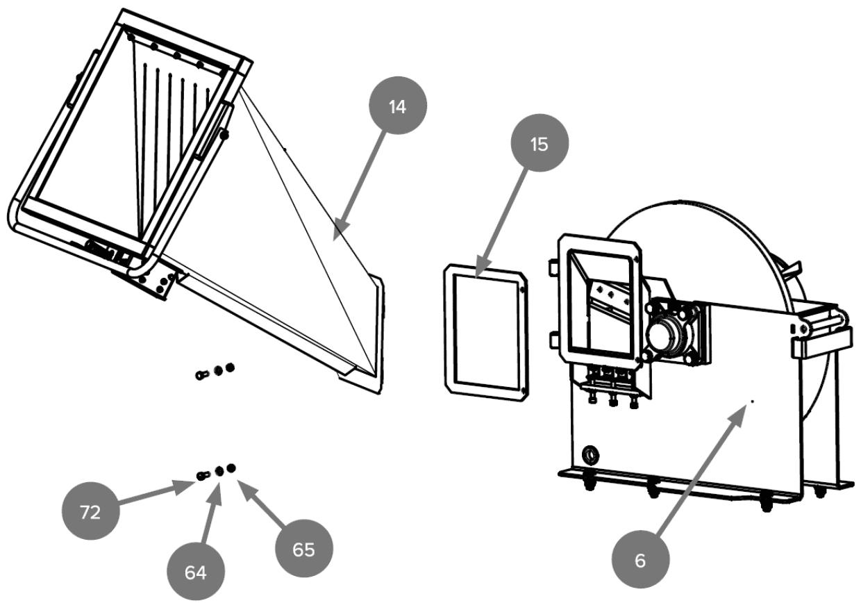
2) Installation of the feed hopper
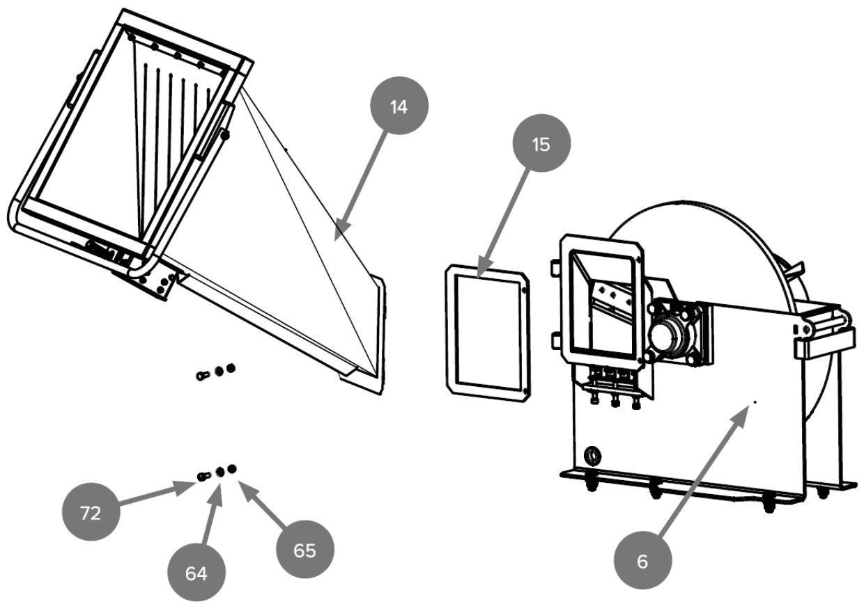
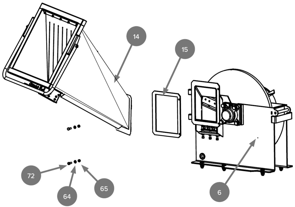
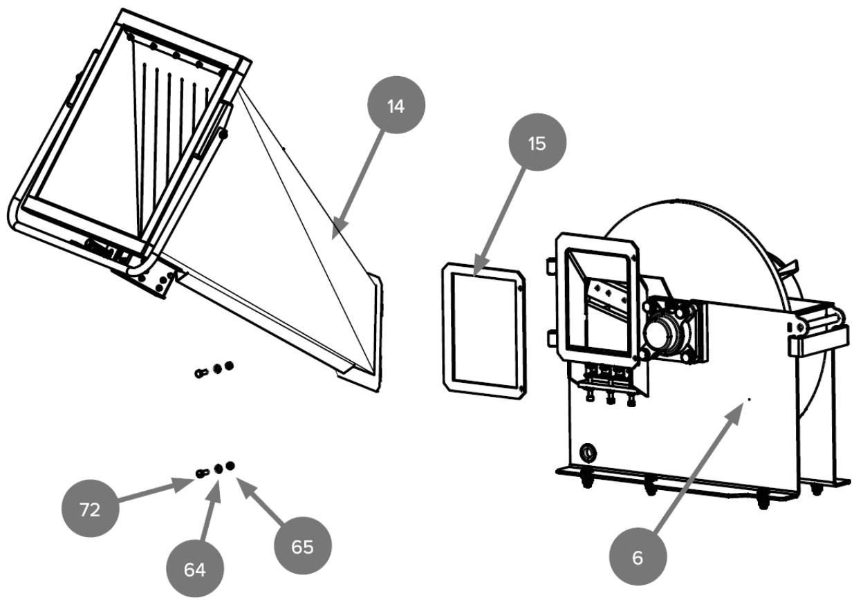
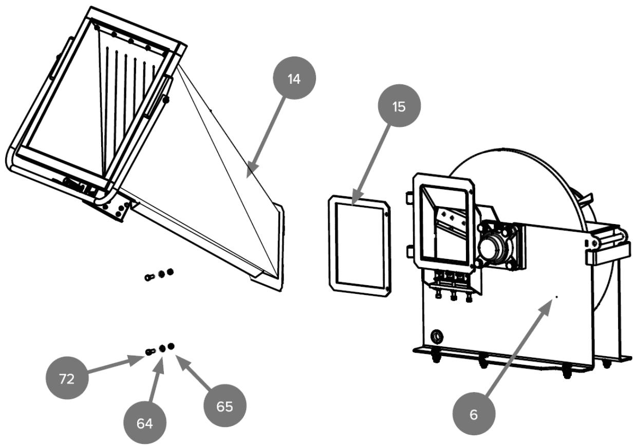
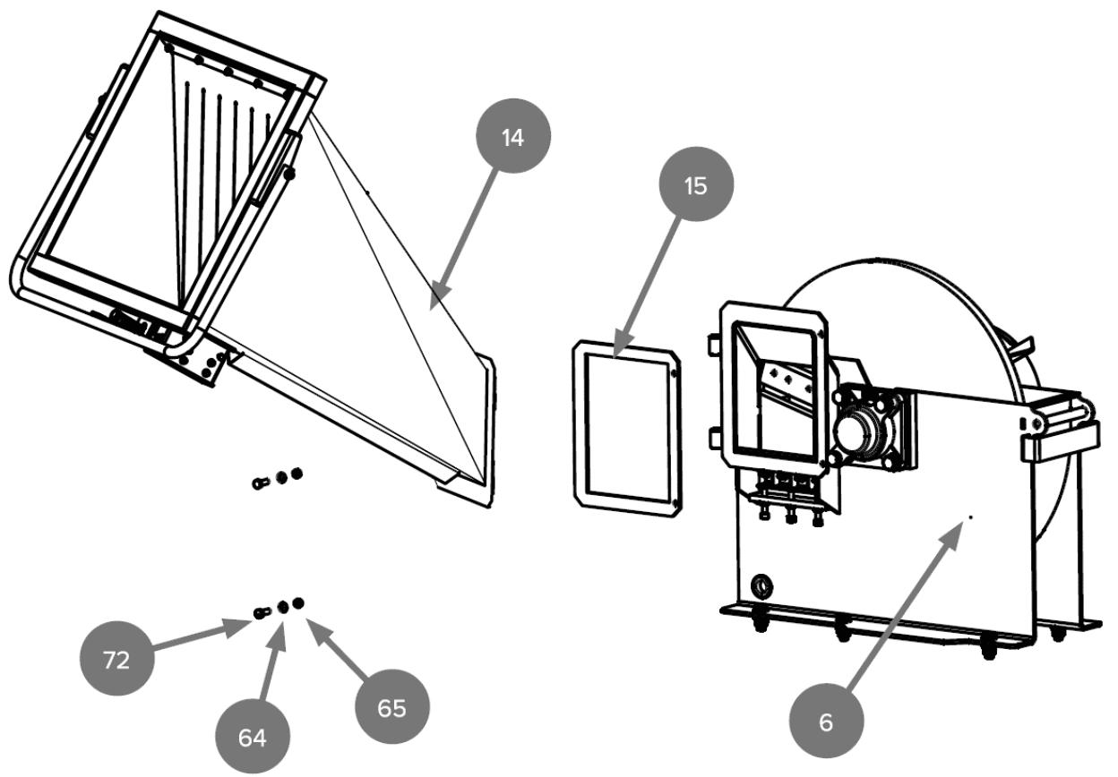
Attach the feed hopper (14) to the cutting disc base (6) with the rubber frame (15) between the two parts and install with the M8x25 hex bolt (72), 8 flat washer (64) and M8 lock nut (65).


3) Towing hitch attachment
a) Attach the coupler (47) to the drawbar (46) with an M12x80 hex bolt (52), a 12 flat washer (53) and an M12 locknut (54).
b) Attach the Towbar (46) to the Chassis (1) with an M12x70 Hex Bolt (61), a 12 Flat Washer (53) and an M12 Lock Nut (54).
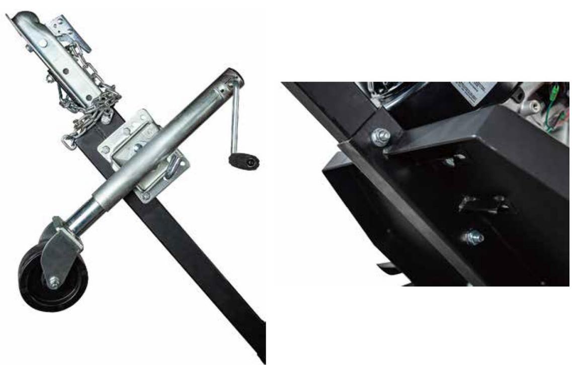
c) Attach the jockey wheel (48) to the drawbar (46) with the M10x60 hex bolt (49), flat washer 12 (53) and flat washer 10 (50).


4) Mounting the discharge chute
a) Place the connection plates (27, 29) on top of the disk cover (26).
b) Place the pivot plate (28) on the connection plates (27, 29).
c) Attach the discharge chute (34) to the swivel plate (28) and connecting plates (27, 29) with flat washer 6 (73), M6 lock nut (74) and M6x20 hex bolt (77).
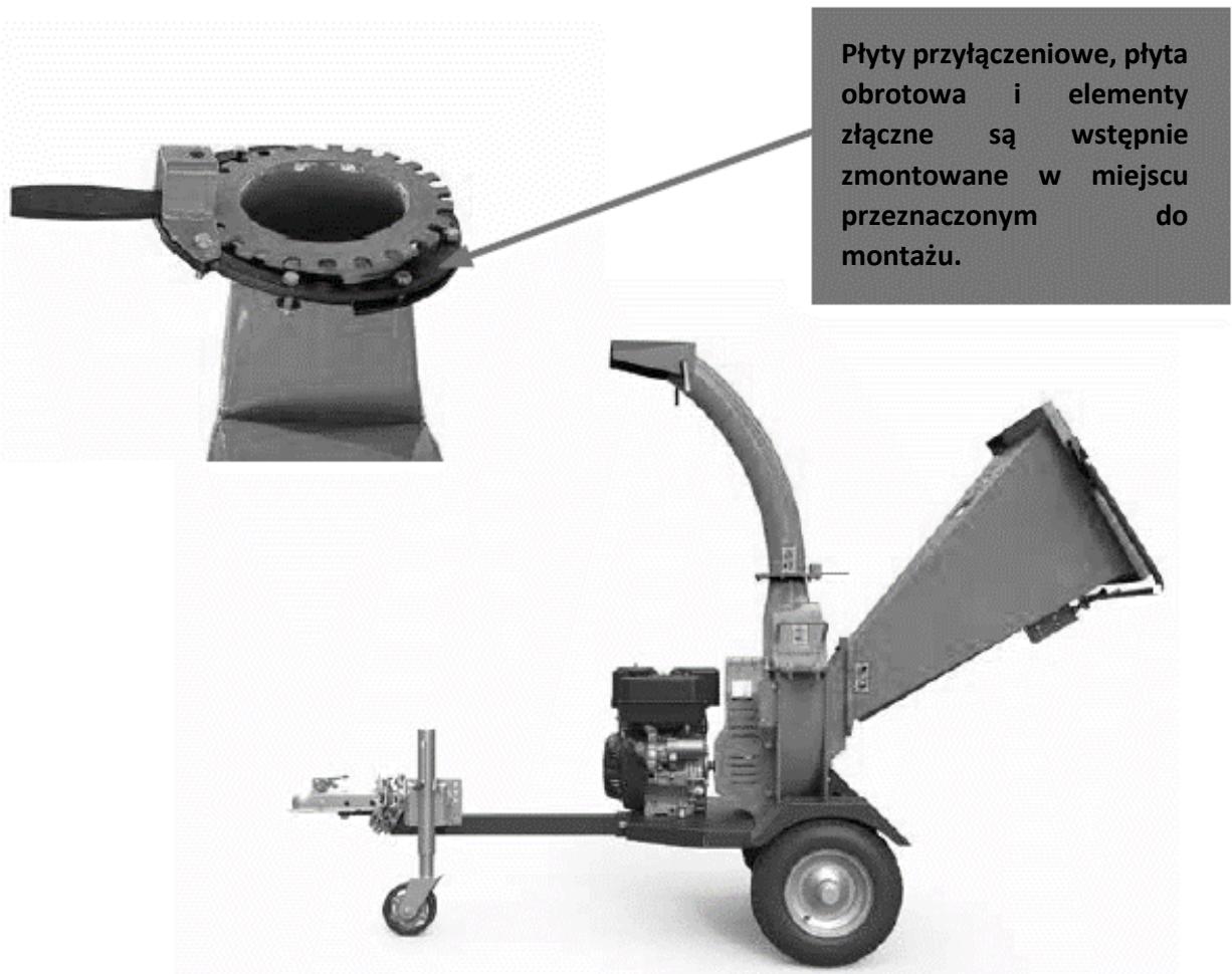
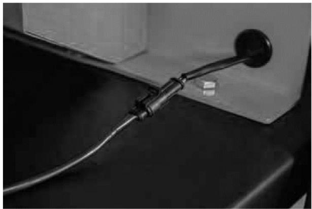
5) Connecting the emergency stop

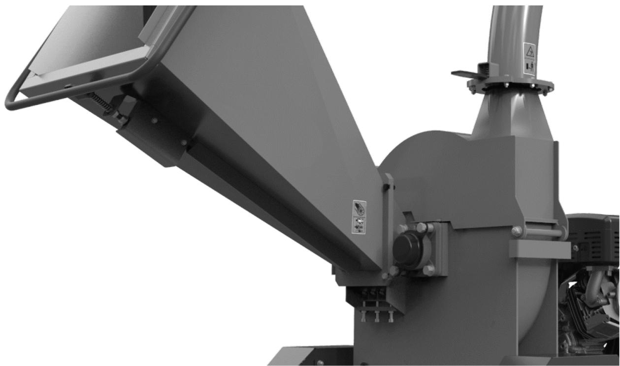
Assembly of models: HT-HECTOR-1200B and HT-HECTOR-1200C
Unpacking
Place the shipping box on a solid, flat surface and carefully remove the cover. Using two people, remove all parts from the box and before beginning to assemble the chipper, check whether any elements are missing.
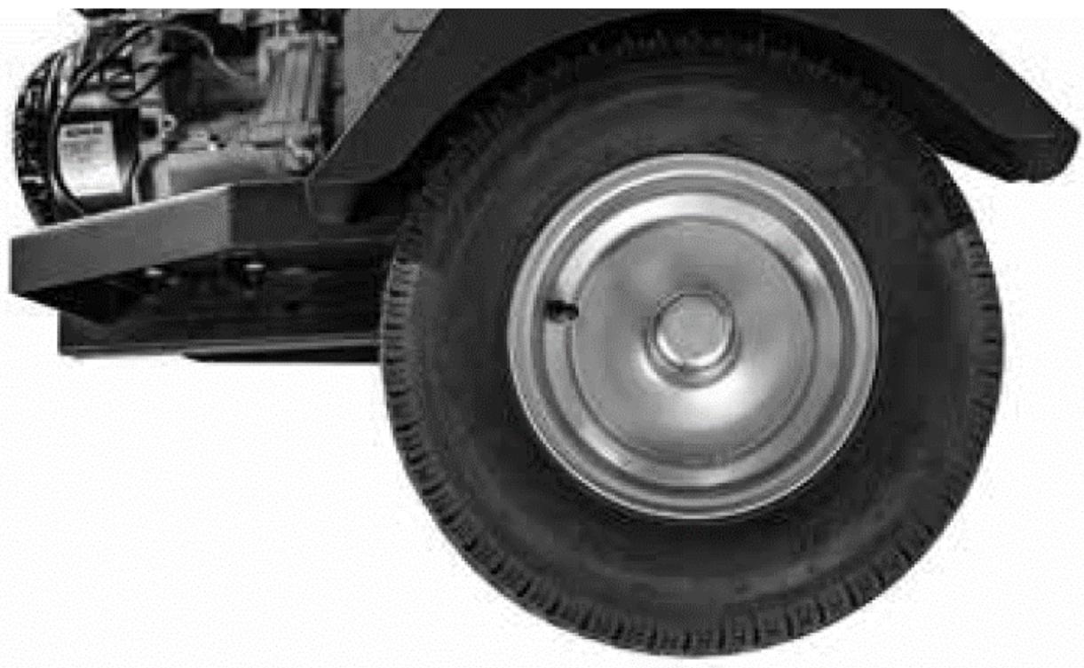
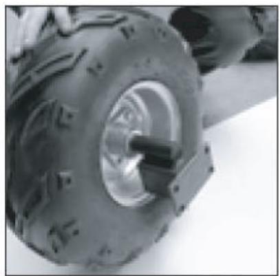
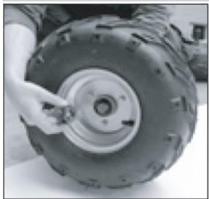
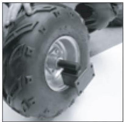
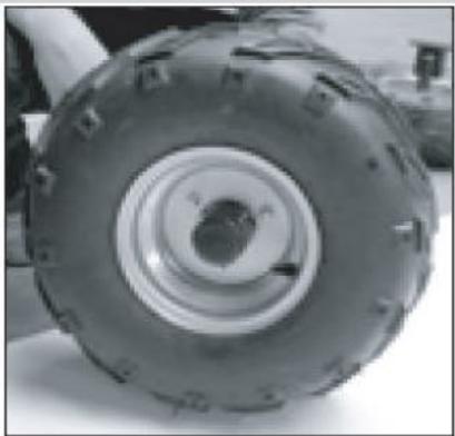
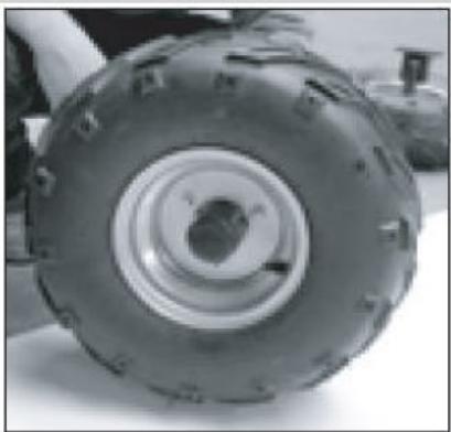
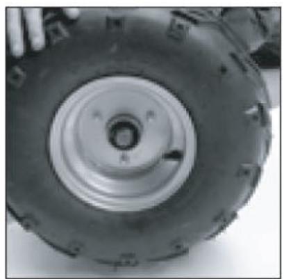
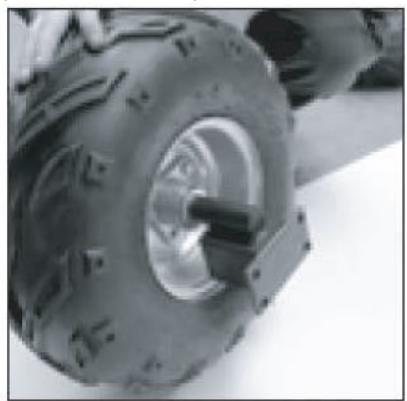
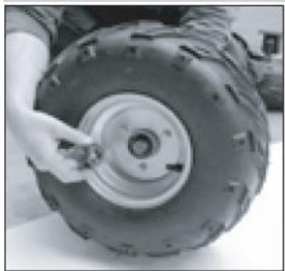
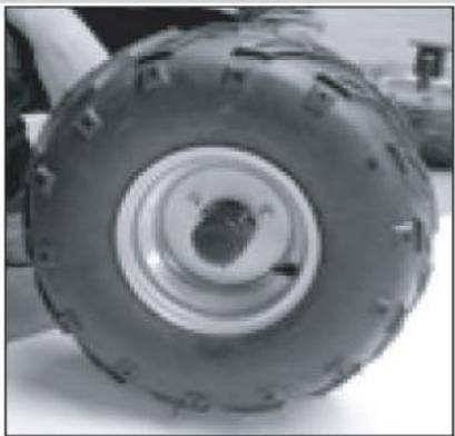
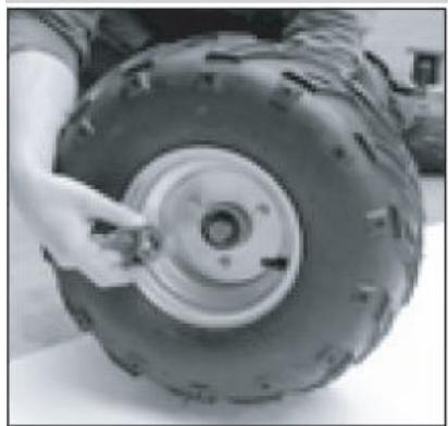
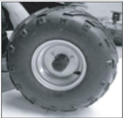
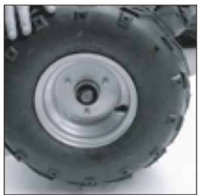
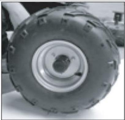
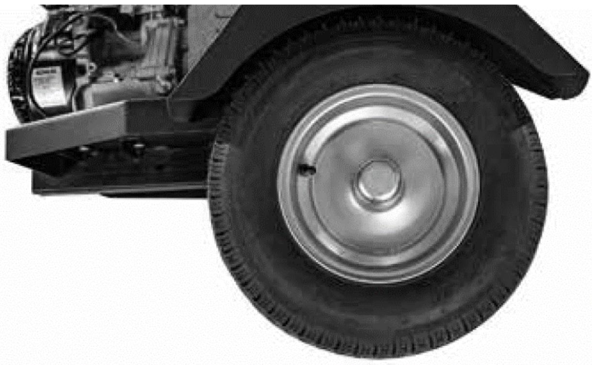
1) Wheels
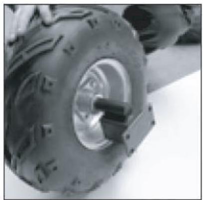
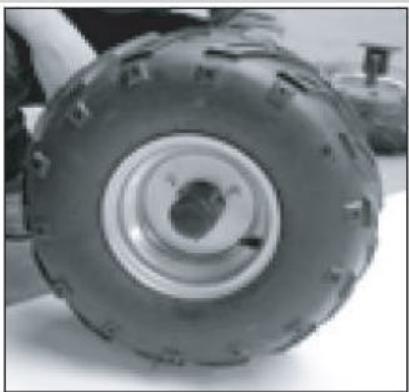
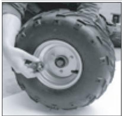
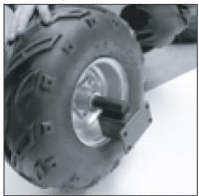
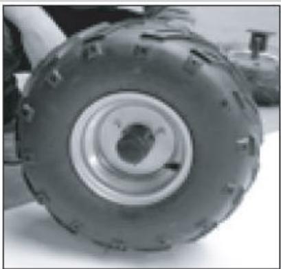
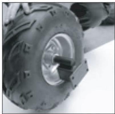
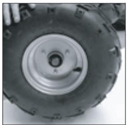
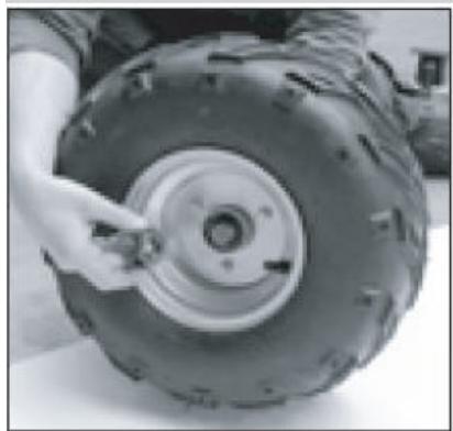
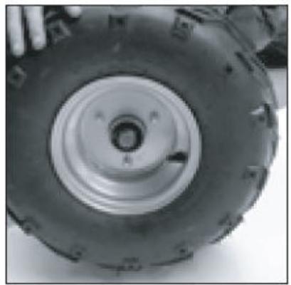
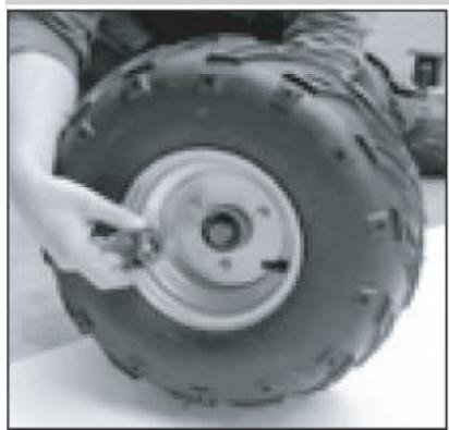
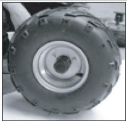
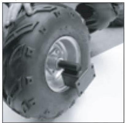
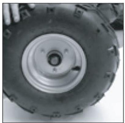
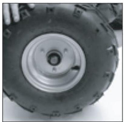
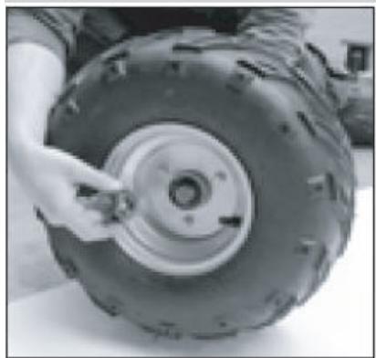
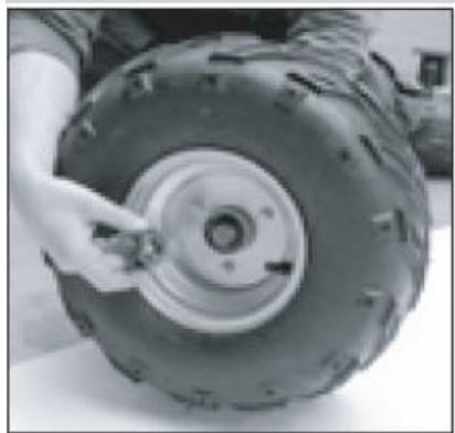
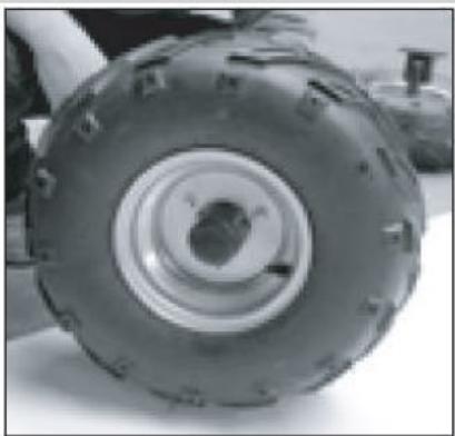
a) Insert the axle through the rim, tighten the nut and secure with a cotter pin. Then replace the dust cover.


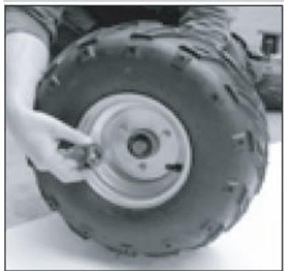
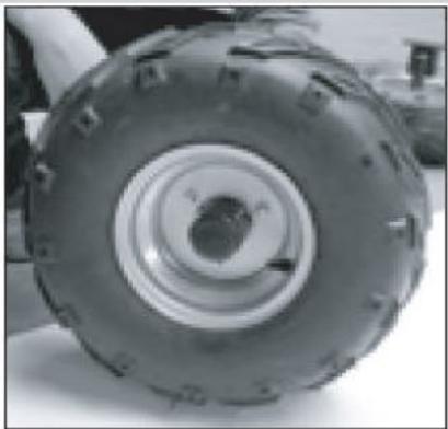
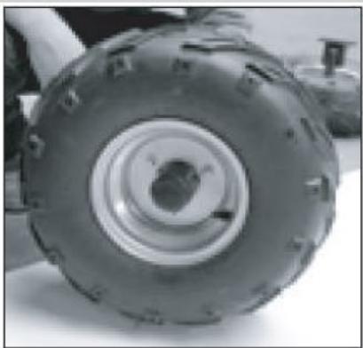
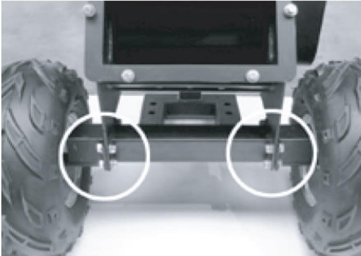
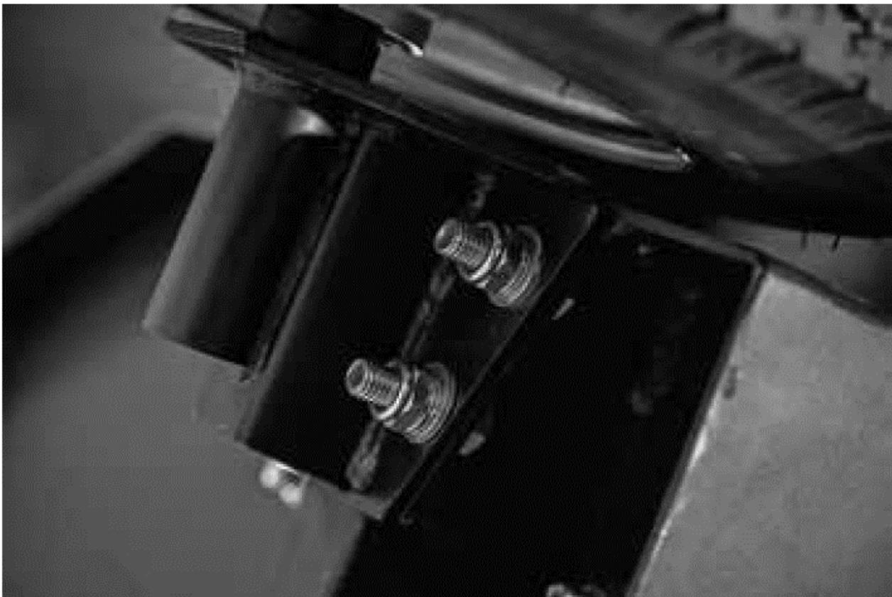
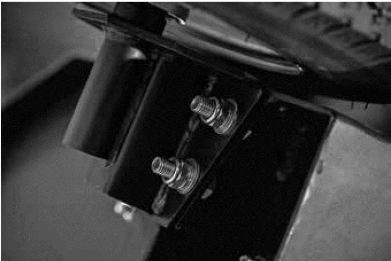
b) Tilt the blade housing slightly back and attach the axle with screws, washers and nuts.
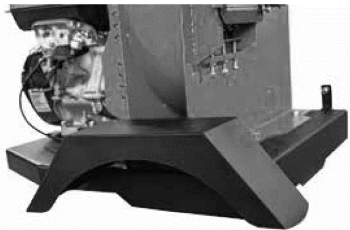
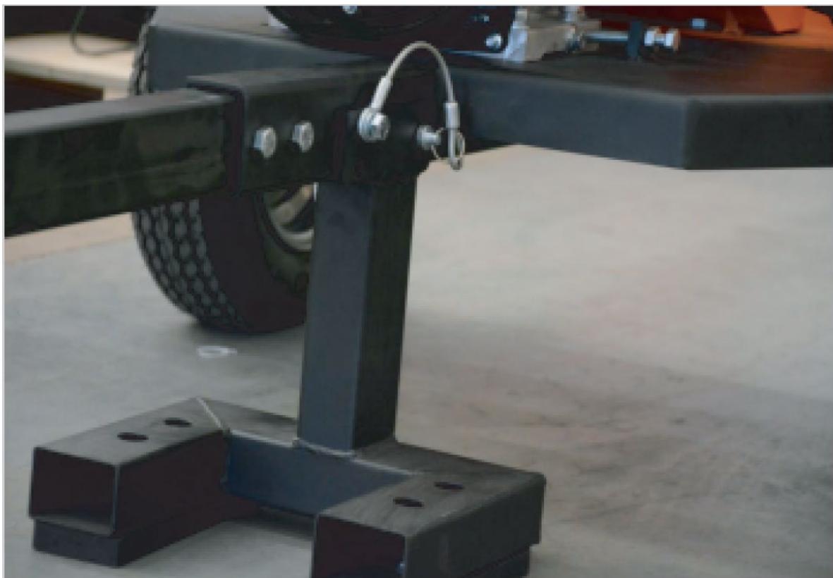
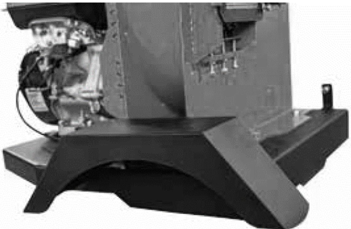
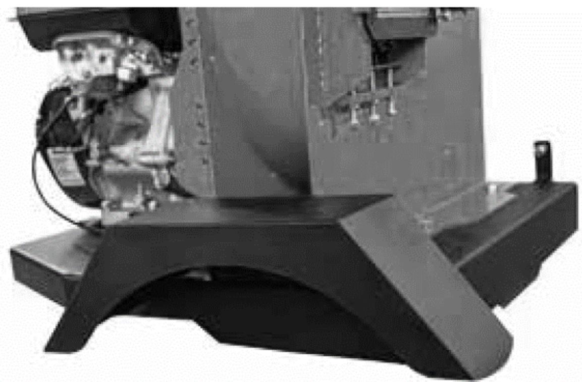
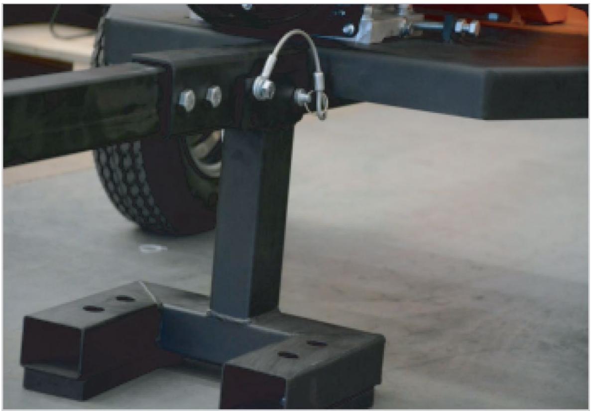
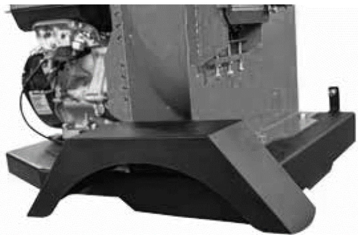
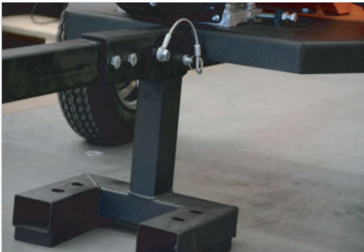
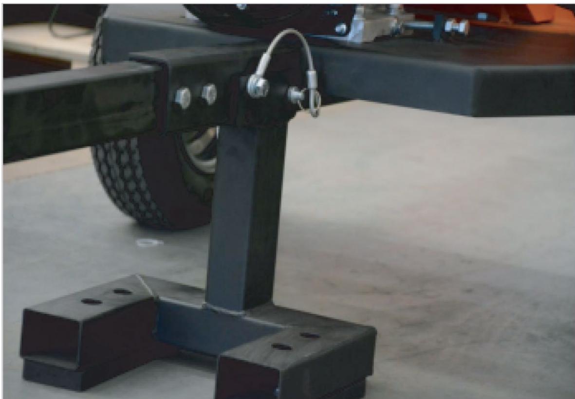
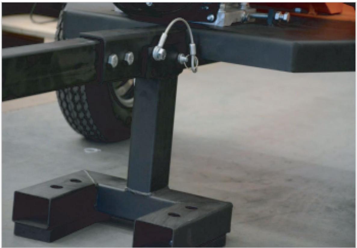
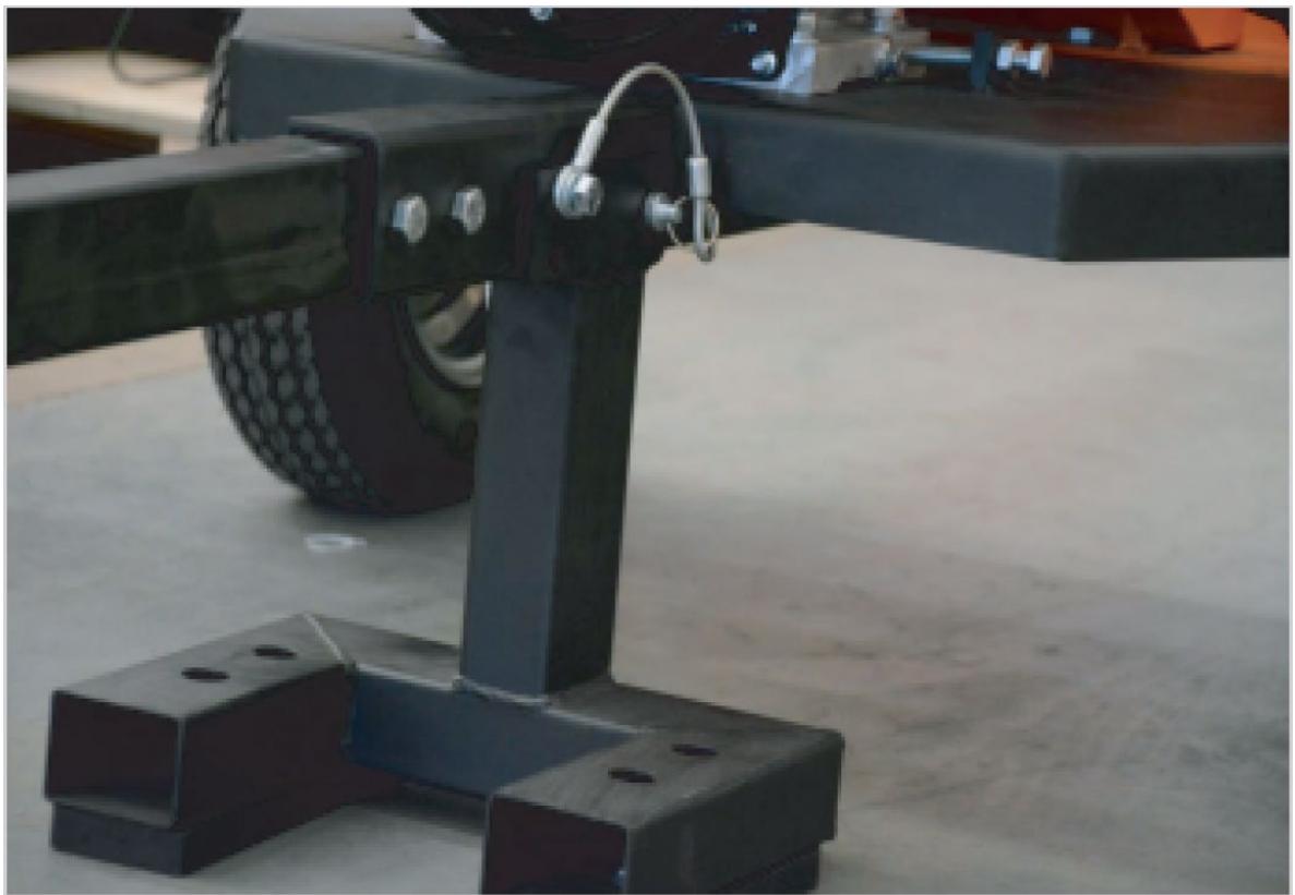
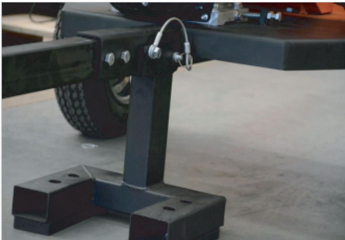
2) Front support
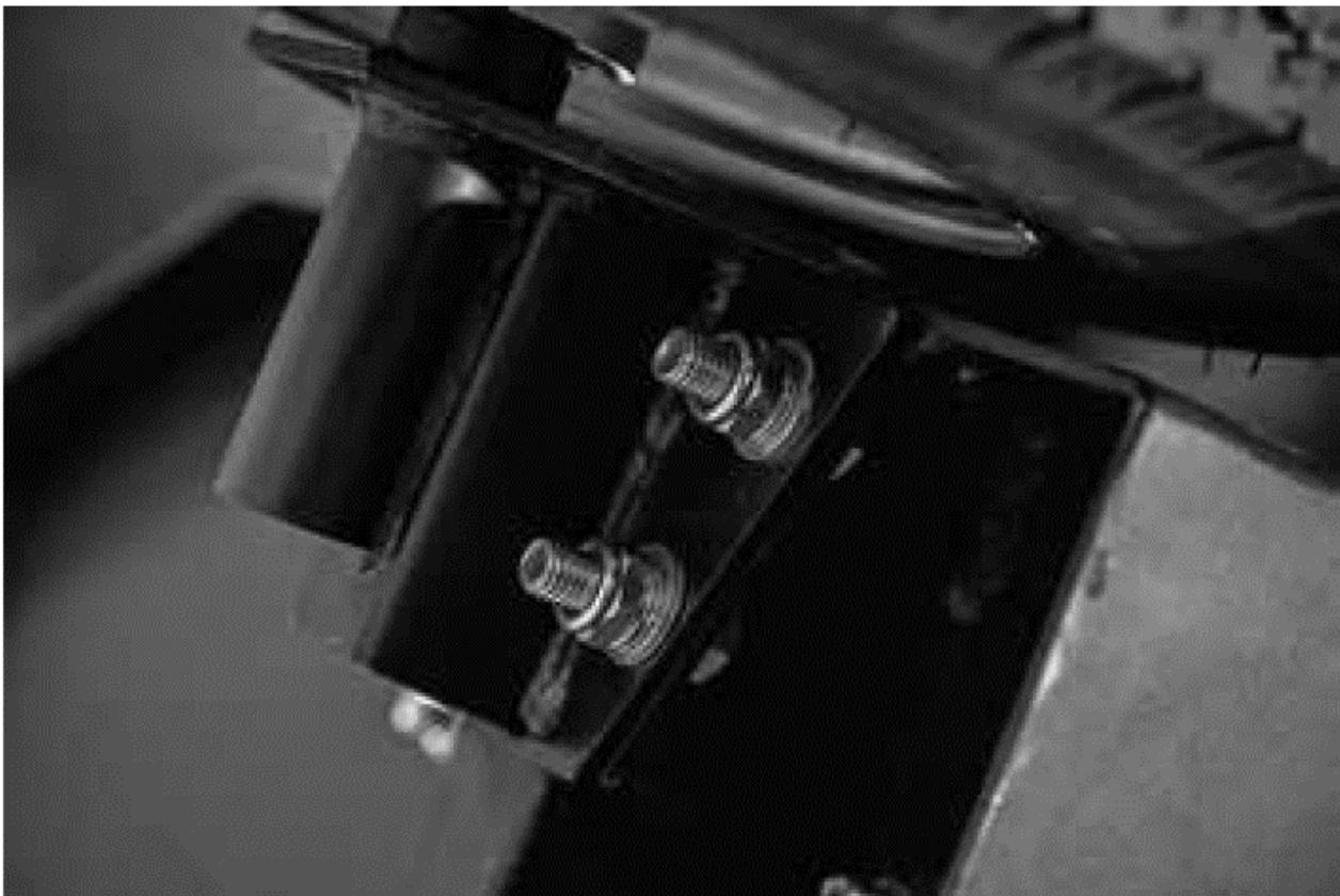
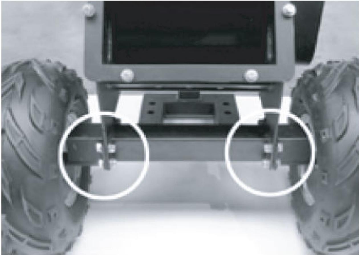
a) Tilt the frame back slightly and attach the front support with screws, washers and nuts.
b) Place the drawbar on the front support and fasten with M12x100 bolts, M12 washers and nuts.

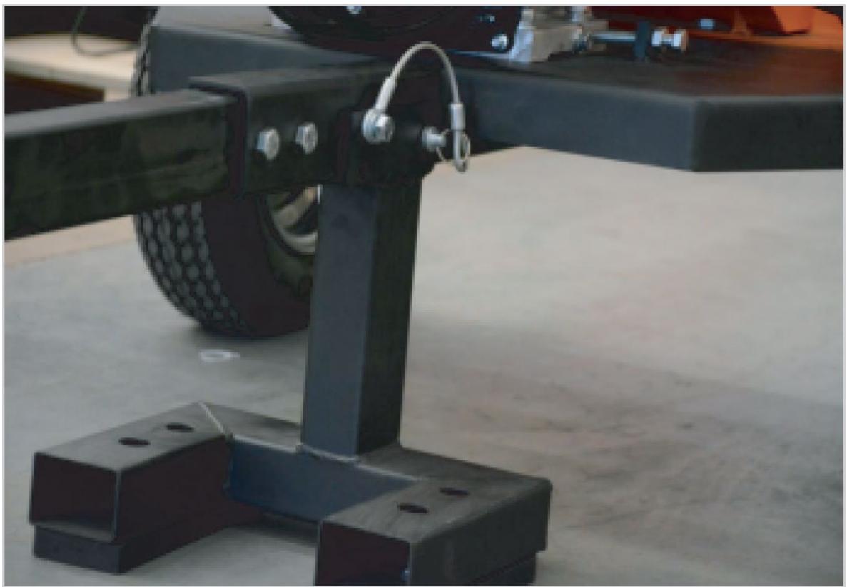
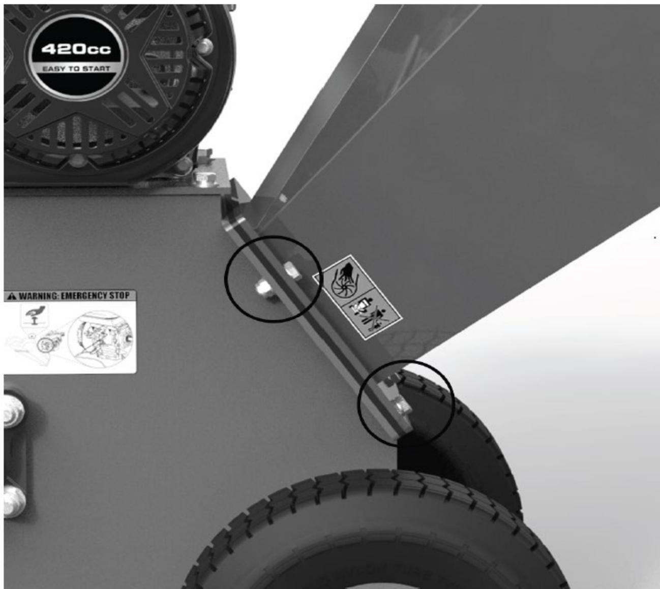
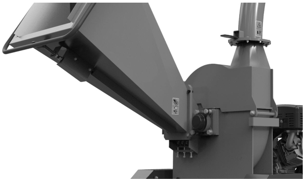
3) Installation of the discharge chute
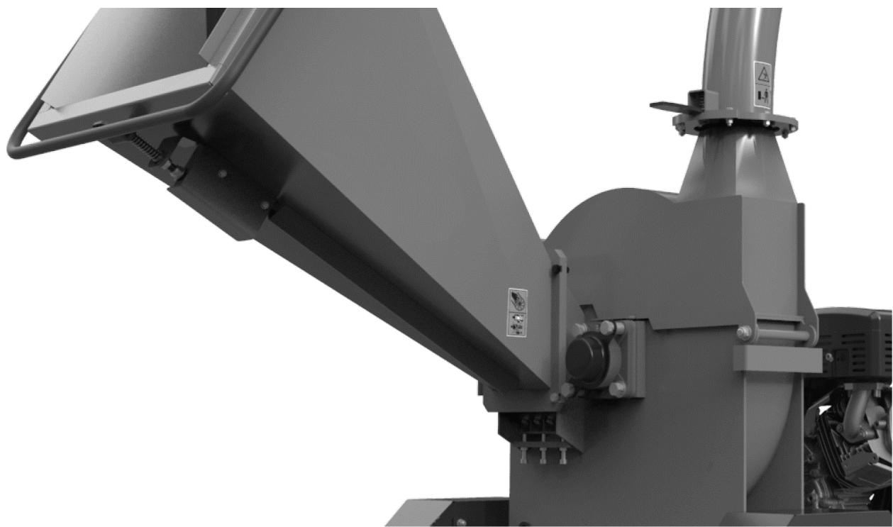
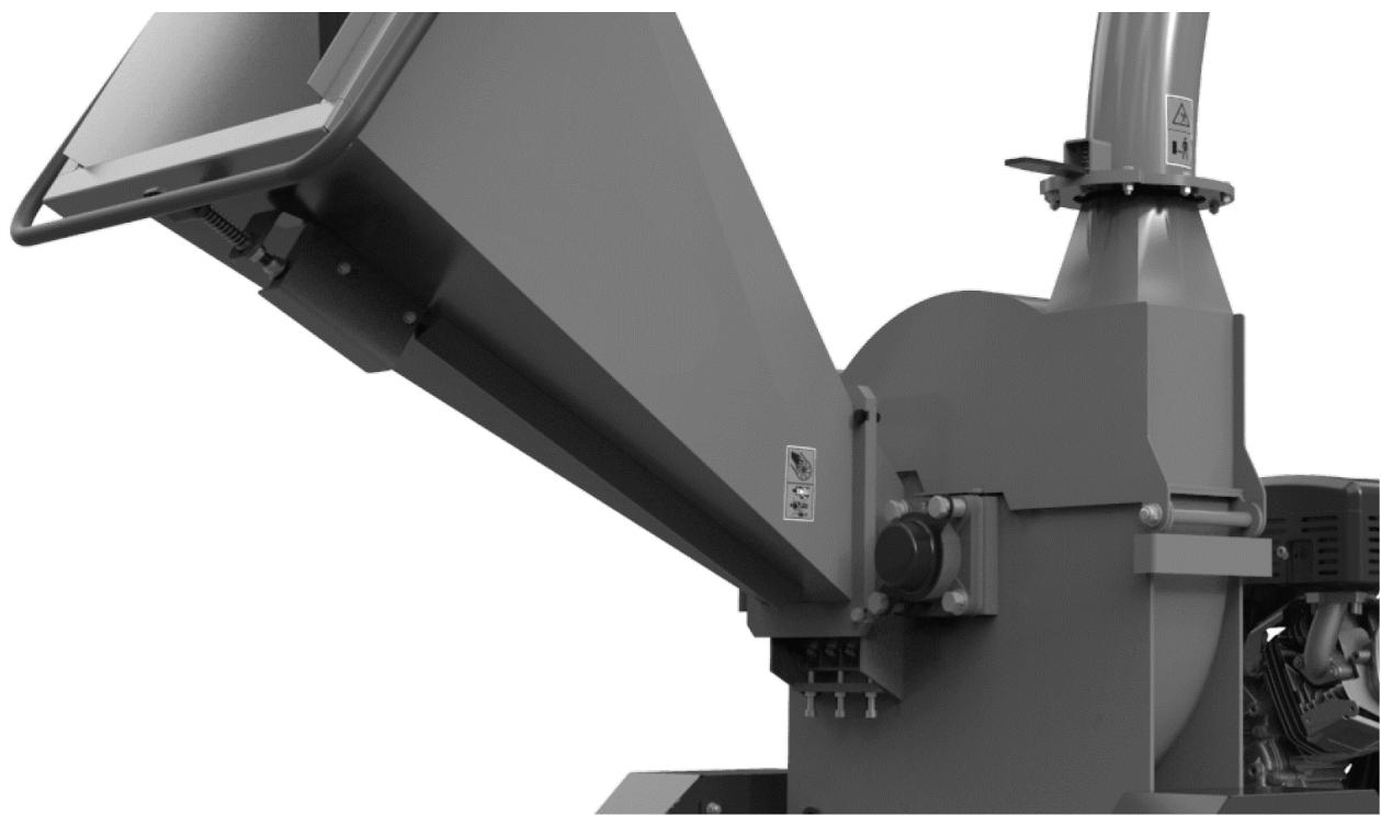
Place the discharge chute on the device body so that the mounting holes align with the holes in the discharge chute. Fasten with screws, washers and nuts.

4) Installation of the loading chute
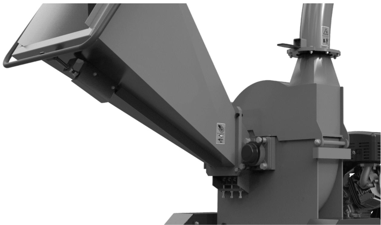
Place the loading chute on the device body so that the mounting holes coincide with the holes in the feeder. Secure with washers and nuts.
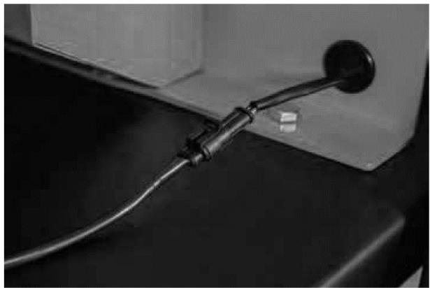
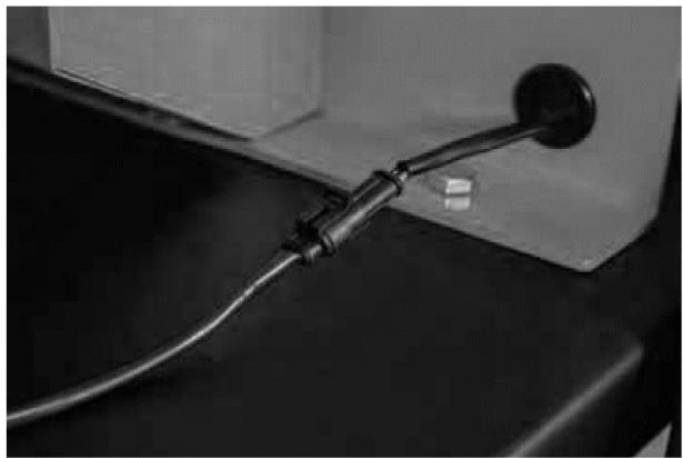
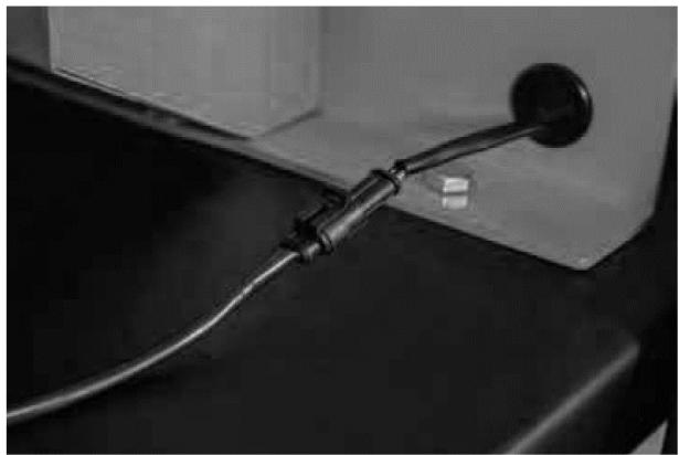
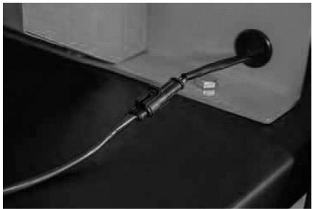
5) Connecting the safety switch
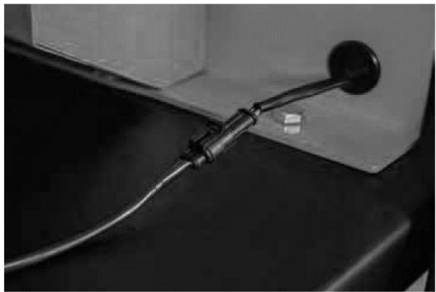
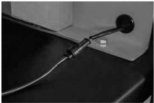
Connect the emergency stop cable to the engine cable

8. Working with the device
Tips for correct use
Always check the oil level before starting the engine!
Further details on engine operation and maintenance can be found in the engine manual.
NOTE: The engine is shipped without oil! Before starting the engine, fill the crankcase with 10w30 oil. When checking or adding oil or fuel, be especially careful to prevent dirt from entering the engine.
Oil
- Use high-quality oil in accordance with the gasoline engine manual.
- Do not use special additives.
Checking and adding oil
- Check the oil level before starting the engine.
- Check the oil level daily or every eight hours.
- Keep the oil level at maximum level.
- Don't overfill.
Oil filling procedure
For instructions on adding oil to your machine, refer to your engine manual.
Oil checking procedure
- Check the oil level before starting the engine.
- Place the engine horizontally. Clean around the oil filler cap and dipstick.
- Insert and remove the dipstick to check the oil level.
- Remove the oil filler cap. Pour in the oil slowly.
- Fill to the mark on the dipstick - check again
- Reinsert the dipstick.
Fuel
- Use clean, fresh, regular unleaded gasoline in accordance with your engine manual.
Adding fuel
- Fill the tank outdoors or in a well-ventilated area, away from sparks, open flames, heat and other sources of ignition.
- If fuel is spilled, wait until it evaporates before starting the engine.
- Turn off the engine and allow it to cool for at least 2 minutes before removing the fuel filler cap.
- Remove the cap. Fill the tank to approximately 38mm below the top of the neck to allow for fuel expansion. Be careful not to overfill. Replace the cap before starting.
Starting and stopping
IMPORTANT : The engine is delivered to the customer without oil. Engine oil must be refilled before starting the engine.
Starting the engine
1) Turn the fuel valve to the "ON" position
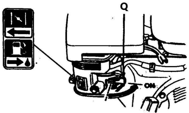
Q – fuel valve
2) Move the choke lever to the "CLOSE" position.
NOTE: If the engine is hot, it is not necessary to move the choke lever.

O - choke lever
3) Move the throttle lever slightly to the left.

P – Throttle lever
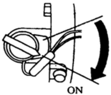
4) Set the engine switch to the "ON" position.
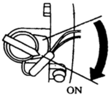
5) Lightly pull the starter rope handle upwards until you feel resistance, then pull quickly.

I – Starter rope
NOTE: Sudden release of the handle may result in impact to the engine. Release the handle slowly, adjusting to the force of the recoil.
Engine speed control
1) Warm up the engine and move the choke lever to the "OPEN" position.
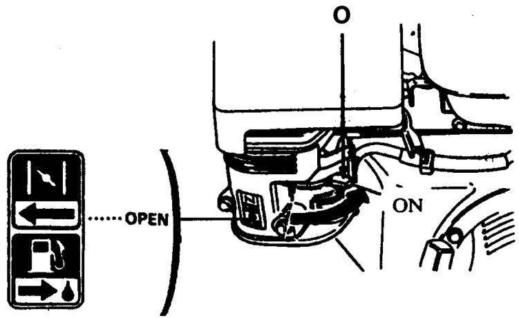
O - choke lever
2) Set the throttle lever to the appropriate position to ensure proper operating speed.
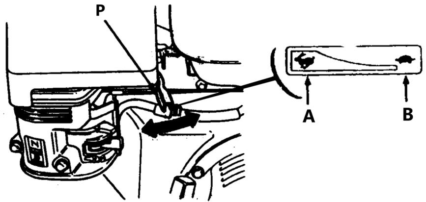
P – throttle lever
A – high speed
B – low speed
Engine stop
In an emergency situation, turn the engine switch to the "OFF" position to stop the engine. In normal situations, to stop the engine:
1) Move the throttle lever to the right (low speed) and down.
2) Set the engine switch to the "OFF" position.
3) Set the fuel valve to the "OFF" position.
NOTE: Sudden stopping at high speed and under heavy load may damage the engine.
Shredding
ATTENTION! Before starting work with the device, test the operation of the device without the material being shredded. If the device does not make any suspicious noises and there are no leaks, you can continue working.
1) Slowly insert the material into the loading hopper. Do not put too much in at once.
2) If necessary, use a long piece of shredded material to push the load.
ATTENTION! Do not put your hands or other body parts into the loading hopper.
NOTE: Due to the possibility of bouncing the wood, the chipper should be loaded while standing on the side of the device.
Usage instructions
- Load material slowly. If the motor makes an unusual noise, the material is being loaded too quickly.
- Roots and other dirty materials will dull and damage knives.
- Remove chips from the device frequently. Otherwise, they may cause a blockage.
- Avoid shredding wet material as it may clog the device. If shredding wet material is necessary, separate it from dry material.
- Do not insert material with a diameter larger than that specified in the technical data table into the device.
- It is better to chop fresh, green wood. The knives will stay sharp longer.
• Always wear gloves and safety glasses when operating the chipper. - If you need to push material into the chipper hopper, use only a wooden stick, never your hands or anything steel.
• Always keep your hands away from the chipper hopper. - Keep the exhaust area away from people, animals, buildings, glass and other objects that obstruct work, cause injury or damage. Wind can also change the direction of flying chips, so be careful.
Before operating, please read all safety instructions contained in this manual.
Important notes
This chipper has been designed to chop trees and branches with a diameter of 12 cm (5") and smaller. never use this machine for any other purpose as it may cause serious injury.
Processing trees and branches with a diameter of 12 cm (5") or smaller
- Your chipper can process dry or green material.
- Insert the branch into the loading chute.
- Hold the branch at the same angle as the chipper tank.
- When a branch becomes short and is in the chipper hopper, walk it or, if necessary, push it into the chipper with the next branch.
- If branches are 5 cm (2") or larger in diameter, feed only one branch at a time into the chipper.
- If the branches are smaller than 5 cm, more than one can be fed into the chipper at a time.
- Green branches are easier to work with than hardwood.
- Make sure you wear protective gloves when loading material into the chipper.
Additional remarks
- Use common sense when using a chipper.
-
Learn to recognize the change in sound of your machine when it is overloaded.
-
Become familiar with favorable operating conditions and avoid those that may overload and damage the machine.
- If the machine stalls due to overload or any other reason, stop it immediately.
-
If you jam the machine and do not stop the engine, it may:
-
Burn the strip
- Destroy the clutch
This damage can be costly and is not covered by warranty. For this reason, it is important to turn off the machine immediately if it jams.
- Only the operator's experience will tell you how to load trees and branches quickly.
- Before starting the chipper, check that the flywheel will rotate freely.
• Each time you use the chipper, visually inspect the chipper blade for damage. - Before each use, check the condition of the blade, the condition of the wear plate and the nuts and bolts holding the blade in place for tightness.
- To move a pile of processed material, use a shovel, rake or long-handled tool. Never use your hands or feet.
Removing a blockage
- Stop the engine.
- Disconnect the spark plug wire and keep it away from the spark plug.
- Remove all material remaining in the chipper hopper.
- Using the wrench, turn the drum shaft, first clockwise, then counterclockwise, until the jam is removed.
- Remove the deflector.
- Check whether the deflector is not clogged. If so, remove them with a branch.
- Use a piece of wood to loosen and remove any material remaining in the chipping chamber.
- Reinstall the deflector.
- Reconnect the spark plug wire.
- Start the machine and allow the material from the chipping chamber to flow through the deflector.
- If the chamber is not empty and the drum is still jammed, repeat the above process.
- Before attempting to process larger amounts of material in the chipper, make sure the chopping chamber is clean.
9. Cleaning and maintenance
Applies to the HT-HECTOR-1200A model
How to maintain the machine
IMPORTANT: Before each operation, check the blade for sharpness and the nuts and bolts securing it to the flywheel for tightness.
IMPORTANT: Whenever you perform maintenance or inspect the blade, be sure to check the gap between the blade and the wear plate for proper alignment.
If the cutting mechanism hits any foreign object or if the machine begins to make an unusual noise or vibrate, stop the engine and disconnect the spark plug wires from the spark plugs. Wait until the engine has cooled down before performing the following steps:
• Inspect and examine for visible damage.
• Check for loose parts, bolts and nuts.
1) When not in use, keep the chipper out of the reach of children. Make sure the storage area is free of gasoline fumes.
2) After every 8 hours of operation, lubricate the bearings on the chipper side and drive side. To do this, wipe off any dirt, etc. from the grease fittings with a clean cloth, then apply no more than 3 pumps of high-quality general-purpose grease using a hand-held grease gun. Over-lubrication can also damage the bearings. Also check the bearing flange set screws regularly to ensure they are tight.
3) If your steel chipping knife needs to be replaced or sharpened, see the disassembly, sharpening and reassembly section.
4) When installing a new blade, check and adjust the clearance between the blade and the wear plate. This play or gap should be set to 1/16".
5) To adjust this clearance, loosen the four nuts and bolts holding the wear plate in place. The wear plate can be moved up or down (in or out) to obtain the correct gap setting.
6) Before starting the chipper, make sure the flywheel is turning without hitting anything.
7) If the gap between the wear plate and the blade is not set correctly, excessive vibration will occur during chipping and the blade will appear dull. This should be checked every 8-10 hours of operation.
8) If it is ever necessary to disassemble the chipper for repairs, the chipper disc must be reinstalled in the exact same location on the rotor shaft.

A - Flywheel
B - Chipper knife
C - Wear plate
D - 1/16" gap
NOTE: Correct clearance setting is critical to proper machine operation.
Disassembling the knife
1) Stop the engine.
2) Open the top drive casing.
3) Rotate the chipper disc until the four countersunk screws and locknuts securing the blade to the flywheel are visible through the access door.
4) Remove all four bolts and nuts.
Sharpening the blades
- Never attempt to sharpen a chipper blade.
- To ensure proper operation, it is extremely important to maintain a 45-degree angle at all times.
- The chipper blade should be taken to a machine shop for proper sharpening.
- Excessive heat generated during the sharpening process will damage the blades and weaken the metal.
Strap adjustment
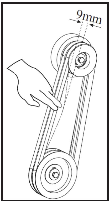
The chipper belt should deflect 3/8" (9.5 mm) under three pounds (0.45 kg) of pressure as shown in the figure below. If this is not the case, adjust according to the instructions below.
1) Remove the belt cover.
2) Loosen the engine bolts.
3) Tighten or loosen the nut until the correct tension is achieved as shown in the figure below.
4) Tighten the engine bolts.

A - Straight edge
B - 3 pounds (0.45 kg) pressure required to move 3/8" (9.5 mm) belt
C - Clutch drum
D - Basic chipper puller
5) Check the alignment of the clutch with the drive pulley by placing a straight edge on both surfaces as shown in the figure below. If adjustment is necessary, correct the setting by sliding the rotor pulley in or out on the rotor shaft. Do not make adjustments by moving the clutch on the motor shaft.
6) Replace the belt cover.

D
A - Clutch
B - Stripes
C - Rotor pulley
D - Straight edge
Replacing the belt
- To replace the belt, follow the belt adjustment instructions above.
- After loosening the engine bolts, remove the old belts and replace them with new ones. Always replace both belts as they come in a matched set. This is required for proper operation.
- Adjust the belt tension and alignment according to the instructions above.
NOTE : Check and re-tension the belts after the initial break-in period, after one hour of use.
Applies to model HT-HECTOR-1200B | HT-HECTOR-1200C
How to maintain the machine
IMPORTANT: Before each operation, check the blade for sharpness and the nuts and bolts securing it to the flywheel for tightness.
IMPORTANT: Whenever you perform any maintenance, service or inspect the blade, be sure to check the gap between the blade and the wear plate for proper alignment.
If the cutting mechanism hits any foreign object or if the machine begins to make an unusual noise or vibrate, stop the engine and disconnect the spark plug wires from the spark plugs. Wait until the engine has cooled down before performing the following steps:
- Inspect and examine for visible damage.
-
Check for loose parts, bolts and nuts.
-
When the chipper is not in use, keep it out of the reach of children. Make sure the storage area is free of gasoline fumes.
- After every 8 hours of operation, lubricate the chipper side and drive side bearings. To do this, wipe off any dirt, etc. from the grease fittings with a clean cloth, then apply no more than 3 pumps of high-quality general-purpose grease using a hand-held grease gun. Over-lubrication can also damage the bearings. Also check the bearing flange set screws regularly to ensure they are tight.
- If your steel chipping knife needs to be replaced or sharpened, please see the disassembly, sharpening and reinstallation section.
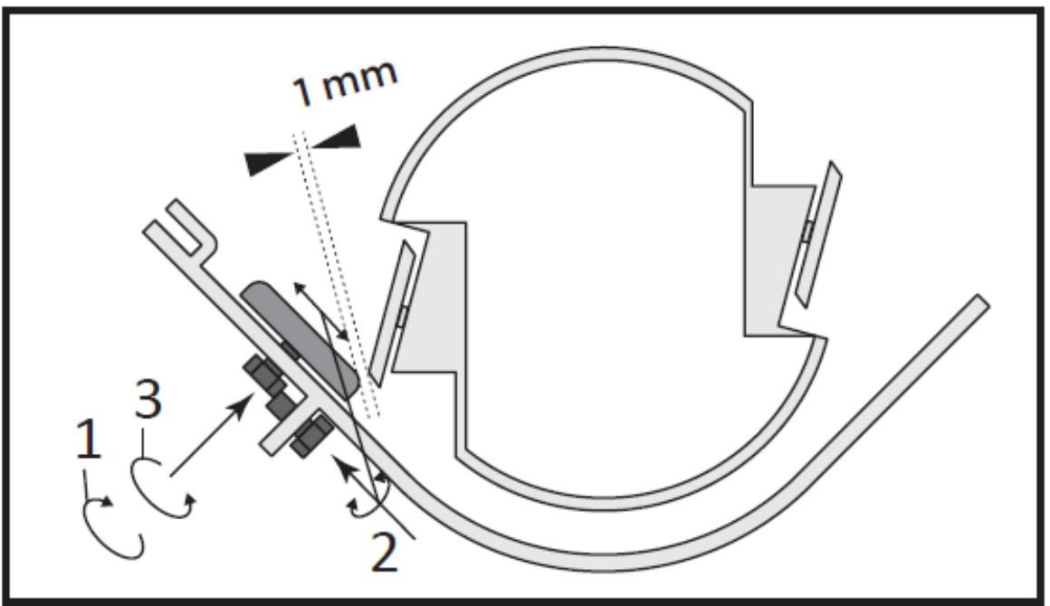
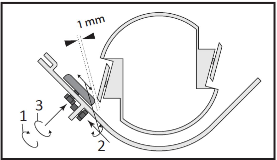
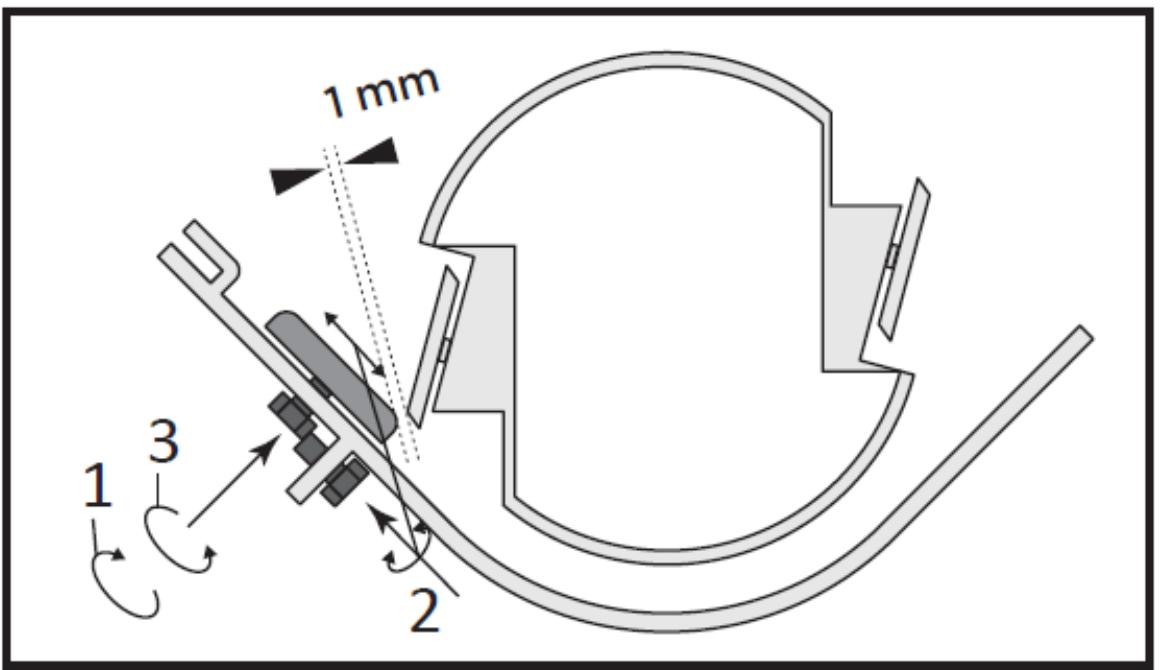
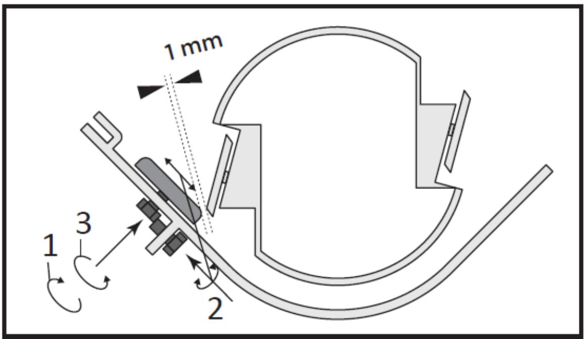
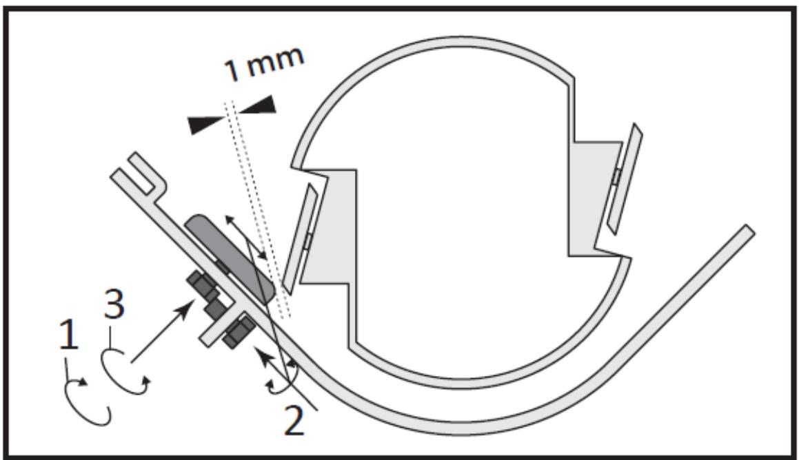
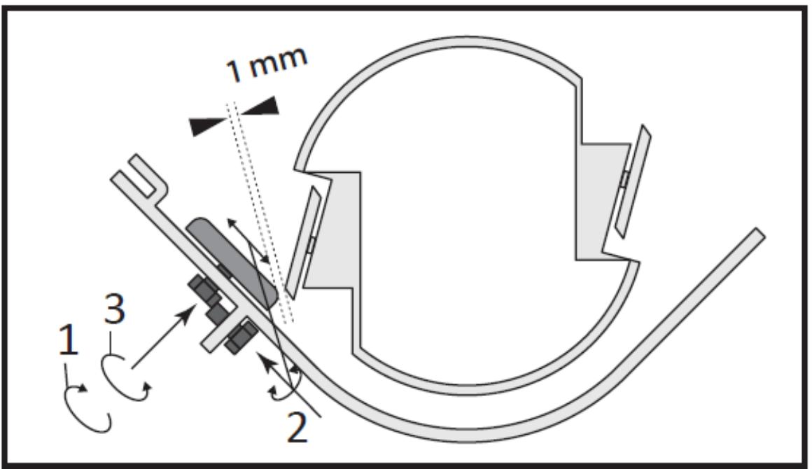
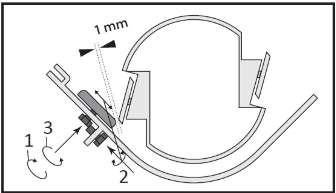
- When installing a new OEM blade, check and adjust the clearance between the blade and the anvil plate. This clearance or gap should be set to 1/16" (1.58 mm).
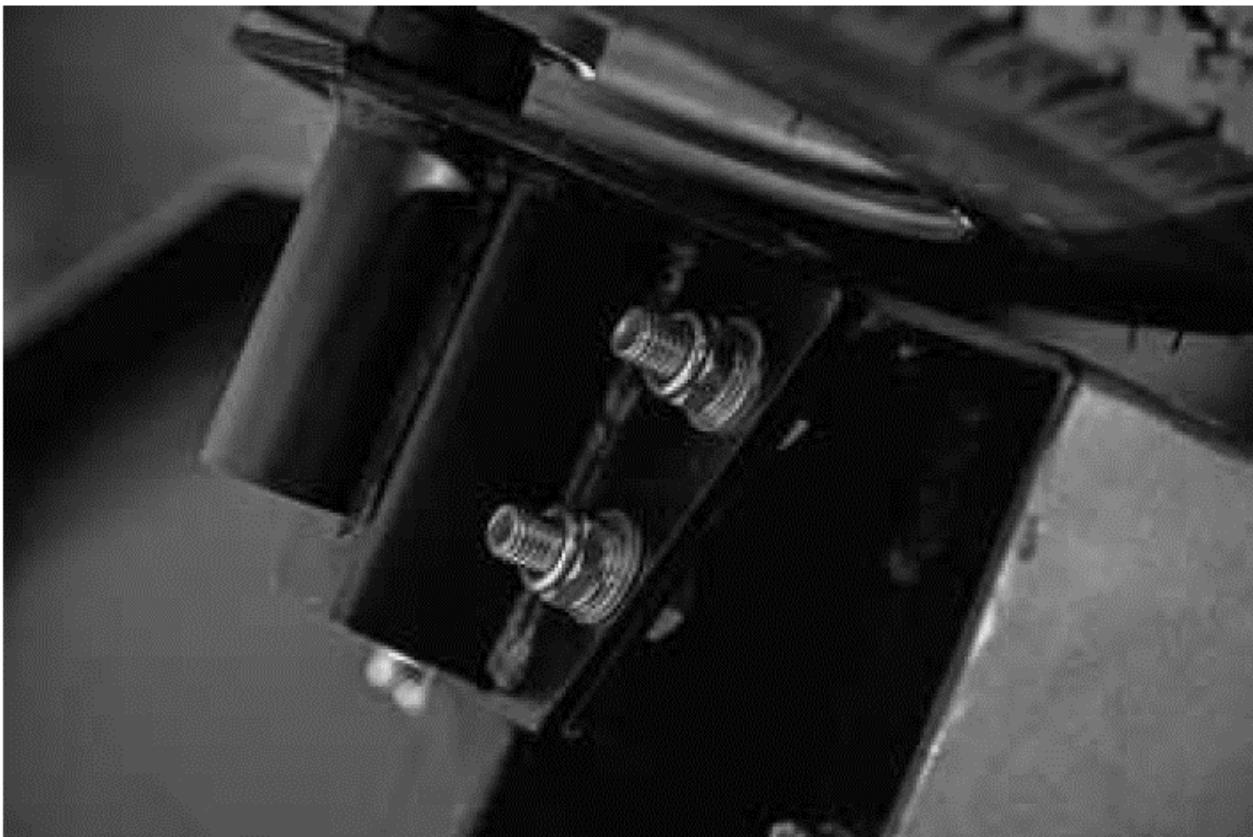
- To adjust this clearance, loosen the three nuts and bolts holding the wear plate in place. The anvil plate can be moved up or down (inward or outward) to achieve proper gap alignment.
- If the gap between the wear plate and the blade is not set correctly, excessive vibration will occur during chipping and the blade will appear dull. This should be checked every 8-10 hours of operation.
Disassembling the knife
ATTENTION! Always wear protective equipment when working with blades. This machine is equipped with two reversible blades. When they lose their sharpness, the blades can be rotated to use the
other edge. Once the other edge is worn out, they need to be replaced. If you notice an increase in vibration, it may be due to worn cutting edges. You will also notice that long strips of material form when the blades become dull or worn.
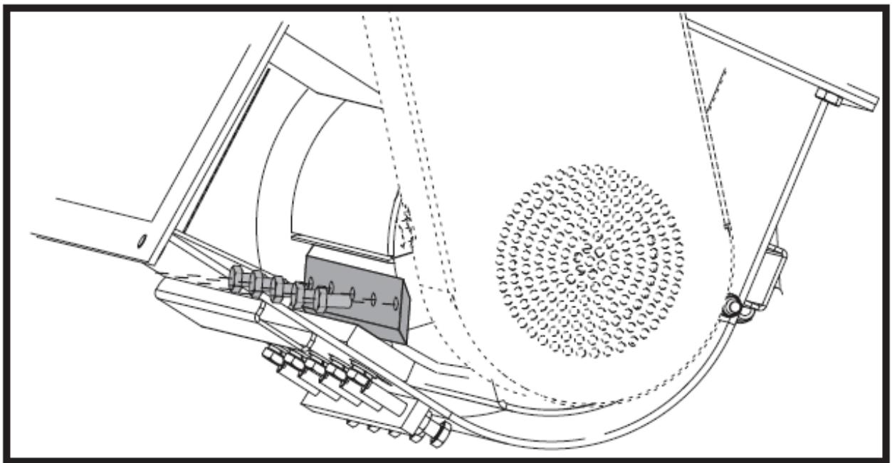
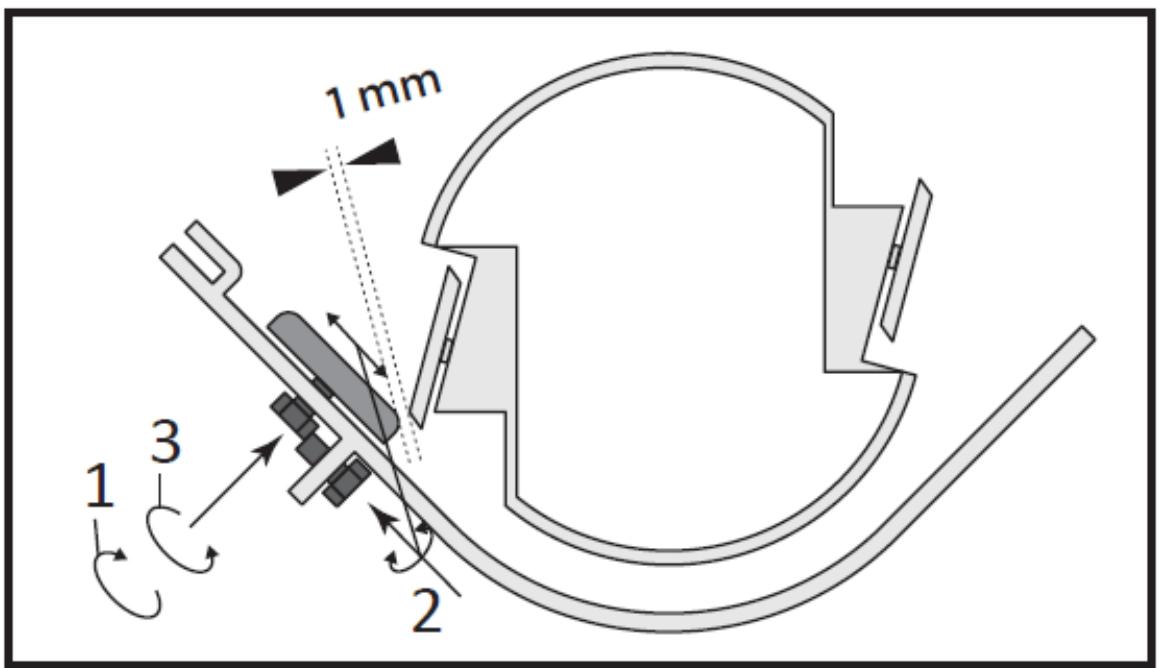
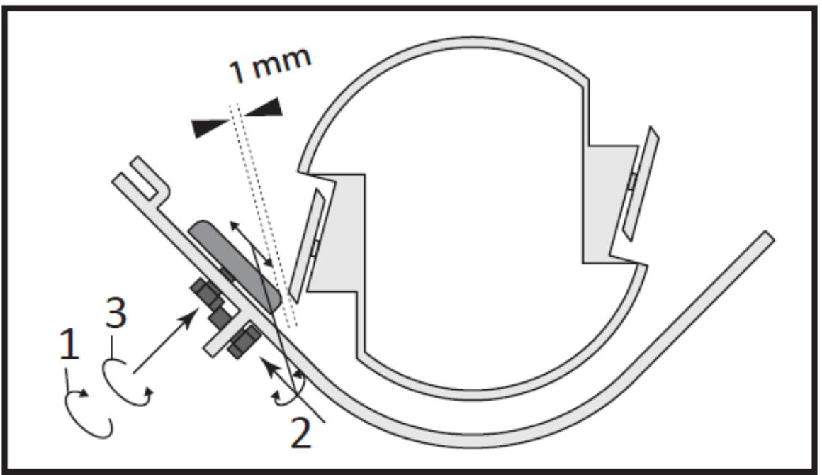
Knife replacement
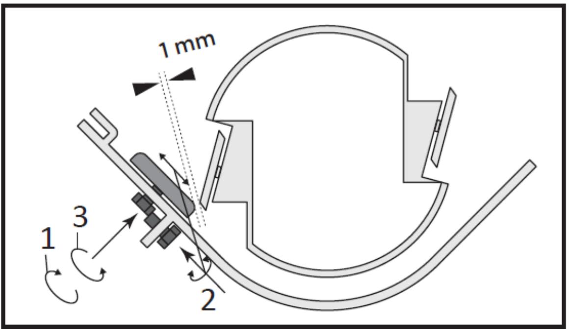
The anvil is also reversible. When the edge of the anvil is worn, it can be rotated. When both edges are worn, the anvil should be replaced.
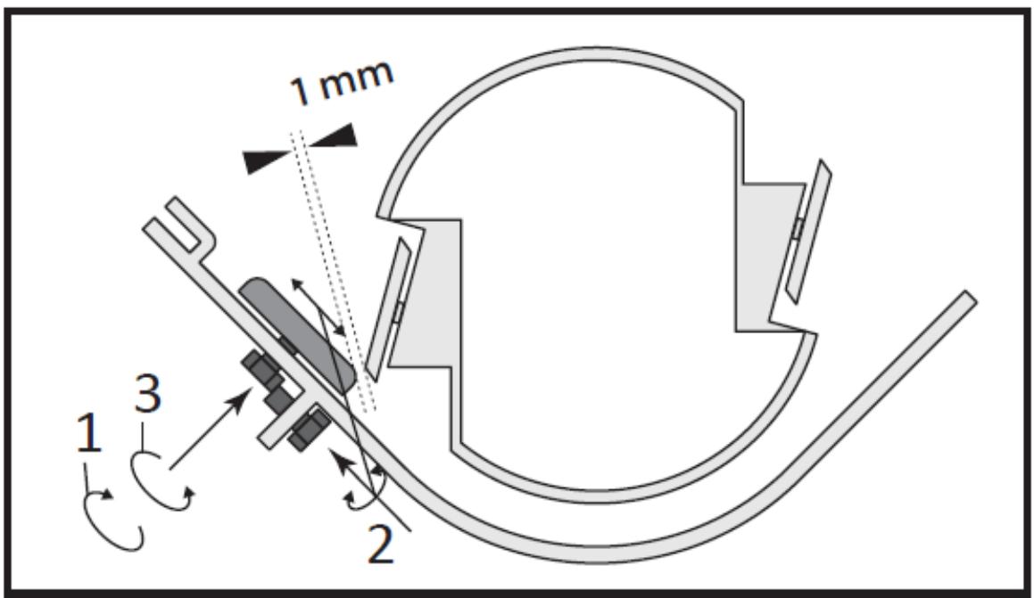
The distance between the blade and the anvil should always be 1 mm.
Sharpening the blades
- Never attempt to sharpen a chipper blade.
- To ensure proper operation, it is extremely important to maintain a 45-degree angle at all times.
- The chipper blade should be taken to a machine shop for proper sharpening.
- Excessive heat generated during the sharpening process will damage the blades and weaken the metal.
Strap adjustment
The chipper belt should deflect 9 mm (3/8 inch) under three pounds of pressure, as shown below. If this does not happen, adjust according to the following instructions:
- Remove the belt cover.
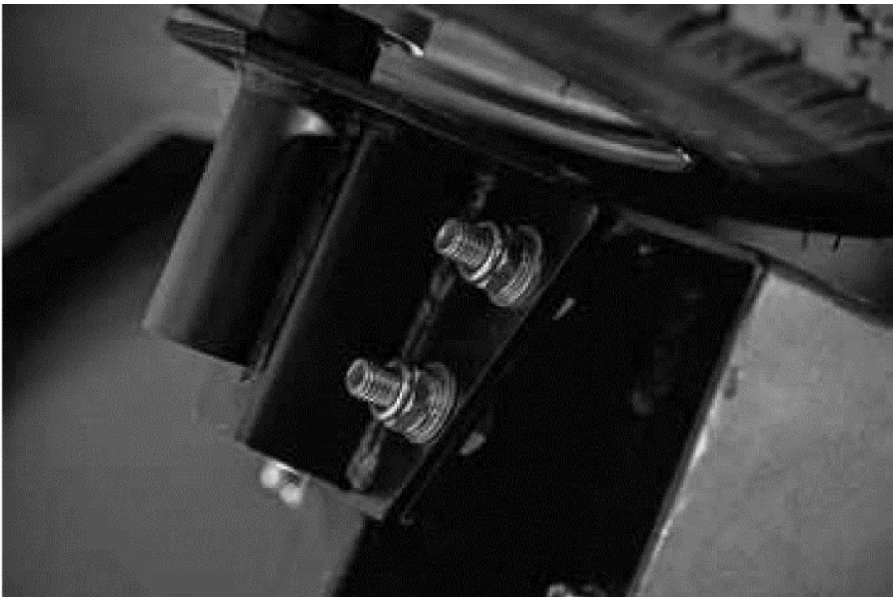
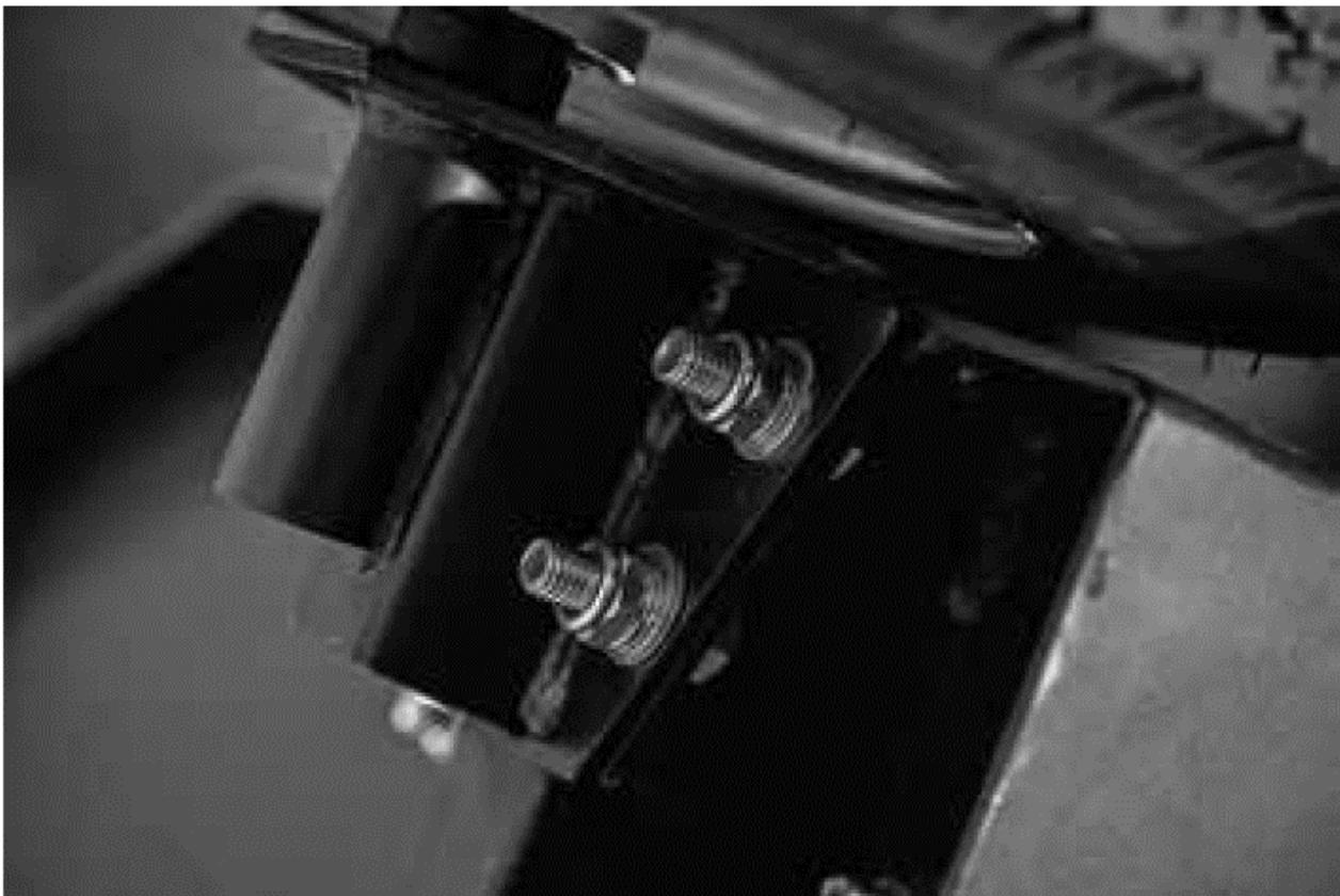
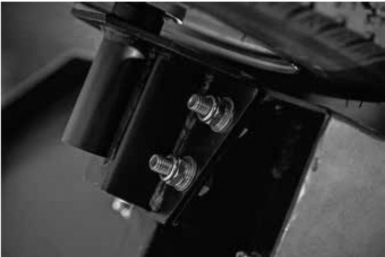
- Loosen the 4 motor plate screws.
- Move the motor using the horizontal adjustment screws until the correct tension is achieved as shown below.
- Retighten the motor screw.
- Replace the belt cover.
Replacing the belt
1) To replace the belt, follow the belt adjustment instructions above.
2) After loosening the engine bolts, remove the old belts and replace them with new ones. Always replace both belts as they come in a matched set. This is required for proper operation.
3) Set the belt tension and alignment according to the instructions above.
NOTE: Check and re-tension the belts after the initial break-in period, after one hour of use.
Applies to all models
Centrifugal Clutch Technical Tips
NOTE: Clutch shoes and springs are subject to normal wear. If you notice reduced clutch performance, it should be checked and replaced if necessary.
The clutch on your machine is designed to be durable and reliable, but it is important to understand the limitations of the clutch. The clutch is designed to ensure engine start-up without load and slippage in the event of excessive overload of the driven device. These features help protect your engine from damage such as damaged crankshafts and starter motors.
The clutch obtains power from the engine speed. The lower the engagement speed and the higher the engine speed maintained, the more torque the clutch can transfer to the driven unit. Do not operate at speeds lower than rated speed.
- When starting the engine, the chipper engine runs without load until the speed of approximately 1000-1200 rpm, at which the centrifugal clutch engages and begins to drive the rotor.
- The correct rotor speed is 2400 rpm +/- 200 rpm when the engine is running at full speed.
- Do not tamper with engine governor settings. The governor controls the maximum safe operating speed and protects the engine. Excessive engine speed is dangerous and may damage the engine and other moving parts of the machine. Contact your authorized dealer for engine adjustment.
- Become familiar with favorable operating conditions and avoid those that may overload and damage the machine.
- Do not overload or attempt to grind the material beyond the manufacturer's recommendations.
This may result in personal injury or damage to the machine. - Learn to recognize the sound of a machine when it is overloaded.
- If the machine stalls due to overload or any other reason, stop it immediately.
- If you lock the machine and do not turn off the engine, it may:
- Burn the strip.
- Destroy the clutch.
- Only the operator's experience will tell you how quickly you can successfully get limbs into the machine.
- Clutch damage can be costly and is not covered by warranty. For this reason, it is important to turn off the machine immediately if it jams.
Clutch maintenance
The centrifugal clutch on this machine is permanently lubricated and requires no oil or grease. If the drum rocks excessively after long periods of use, the drum assembly should be replaced. Always replace shoes and springs in sets. Whenever you replace your shoes, all springs should be replaced.
Clutch disassembly
1) Remove the coupling from the shaft by removing the screw and washers.
2) Slide the coupling off the shaft.
3) Remove the key from the slot.
Installing a new clutch
1) Clean the shaft and remove any burrs.
2) Apply anti-seize compound to the shaft.
3) Place the key in the groove on the shaft.
4) Slide the coupling onto the shaft and secure with the screw, flat washer and lock washer.
5) Tighten the two hex head set screws.
General recommendations for cleaning and storage
a) Before each cleaning, adjustment, replacement of accessories, and when the device is not in use, disconnect the power plug and cool the device completely. Wait until the rotating elements stop.
b) Only agents that do not contain corrosive substances should be used to clean the surfaces.
c) The device should be stored in a dry and cool place protected from moisture and direct sunlight.
d) It is prohibited to spray the device with a jet of water or immerse the device in water.
e) Please make sure that no water gets in through the ventilation holes in the housing.
f) Ventilation holes should be cleaned with a brush and compressed air.
g) The device should be regularly inspected for its technical efficiency and any damage.
Disposal of used devices
At the end of its useful life, this product must not be disposed of with normal municipal waste, but should be taken to a collection point for the recycling of electrical and electronic equipment. This is indicated by the symbol placed on the product, user manual or packaging. The materials used in the device are reusable according to their marking. By reusing, reusing materials or otherwise using used equipment, you make an important contribution to protecting our environment.
Your local administration will provide you with information about the appropriate disposal point for used equipment.
10. Troubleshooting
WARNING
Before performing any maintenance or inspection procedure, stop the engine and wait five minutes to allow all parts to cool. Disconnect the spark plug wire, keeping it away from the spark plug.
| Problem | Possible cause | Action |
| The engine does not start | 1. Out of fuel.2. The choke lever is not in the START position.3. Low quality or spoiled old gasoline.4. Dirty fuel lines.5. The spark plug cap is not securely attached.6. Dirty spark plug.7. No compression in the engine. Problem after long storage period.8. Low engine oil level. | 1. Refuel.2. Set the choke lever to the START position.3. Use fresh unleaded gasoline.4. Clean the lines with fuel additive. Heavy deposits may require further cleaning.5. Connect the spark plug wire correctly.6. Remove and clean/replace the spark plug7. Lubricate the cylinder, pour a tablespoon of oil into the spark plug hole. Move the pistons a few times by slowly pulling the starter rope and try to start again.8. Top up engine oil to the appropriate level. |
| The engine exhaust is black | 1. Dirty air filter.2. Choke lever in closed position. | 1. Replace the air filter.2. Set the choke lever to the closed position. |
| The engine suddenly stops | 1. Fuel tank empty or full of contaminated or low-quality gasoline.2. Low oil shutdown.3. Spark plug cap disconnected or incorrectly connected. | 1. Refill the fuel tank with fresh unleaded gasoline.2. Top up engine oil to the appropriate level.3. Install the spark plug cap correctly. |
| The motor runs but material is not ejected | 1. Clogged exhaust channel.2. The engine does not run at full speed. | 1. Remove impurities.2. Set the throttle to the FAST position. |
| Slow chopping or engine stalling | 1. The branch diameter is too large.2. The throttle is set to the slow position.3. The branches are very hard or dry. | 1. Do not process branches with a diameter larger than 50 mm.2. Adjust the throttle to increase engine speed.3. The material cannot be shredded. |
| Suspicious noise or vibration while grinding material | 1. Rotor overloaded with material.2. The blades are broken, bent or loose.3. Blades blocked. | 1. Allow the unit to clean itself before adding material to the inlet hopper.2. Check correct assembly. Tighten or replace as necessary.3. Check for obstructions and debris. Repair or replace as necessary. |
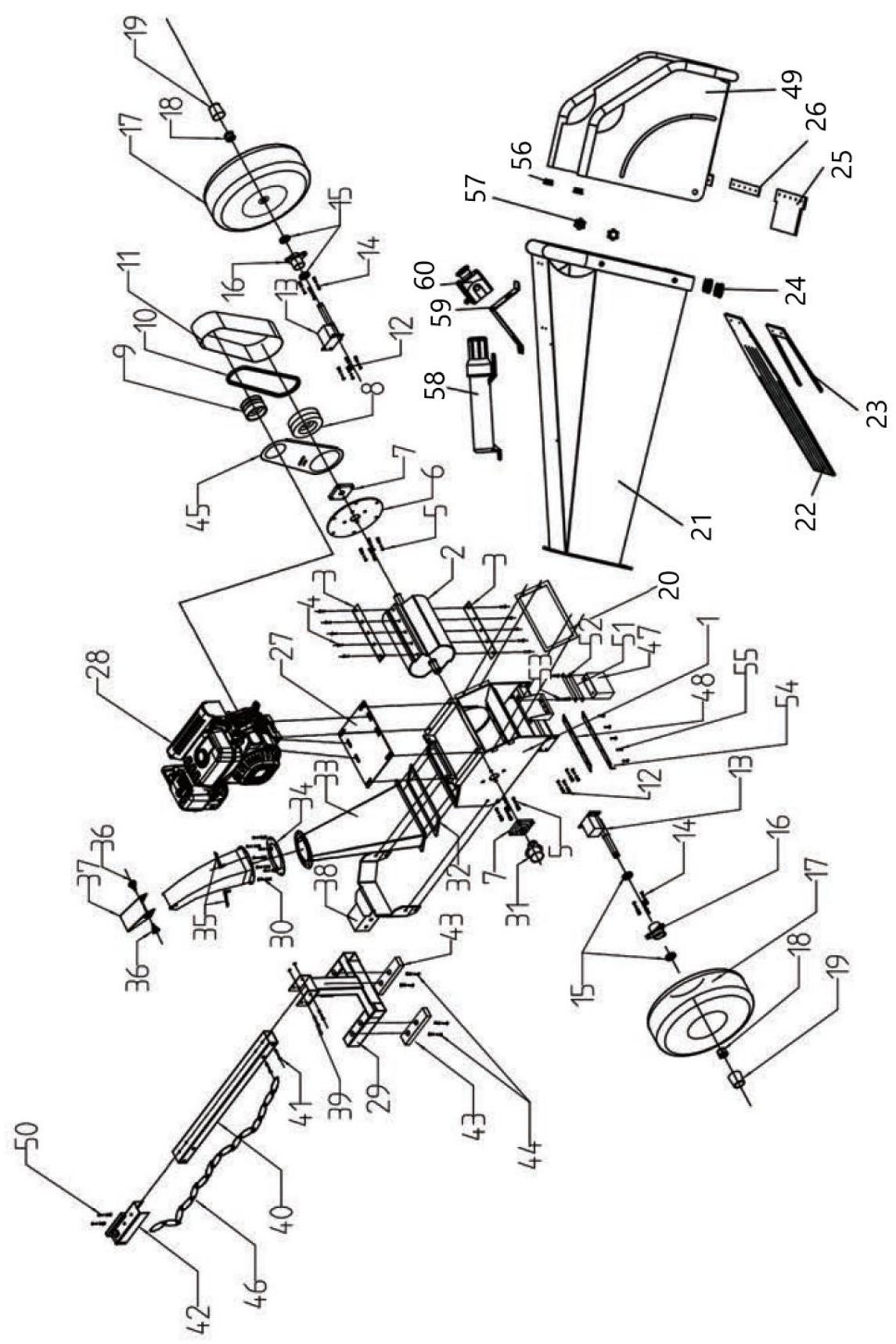
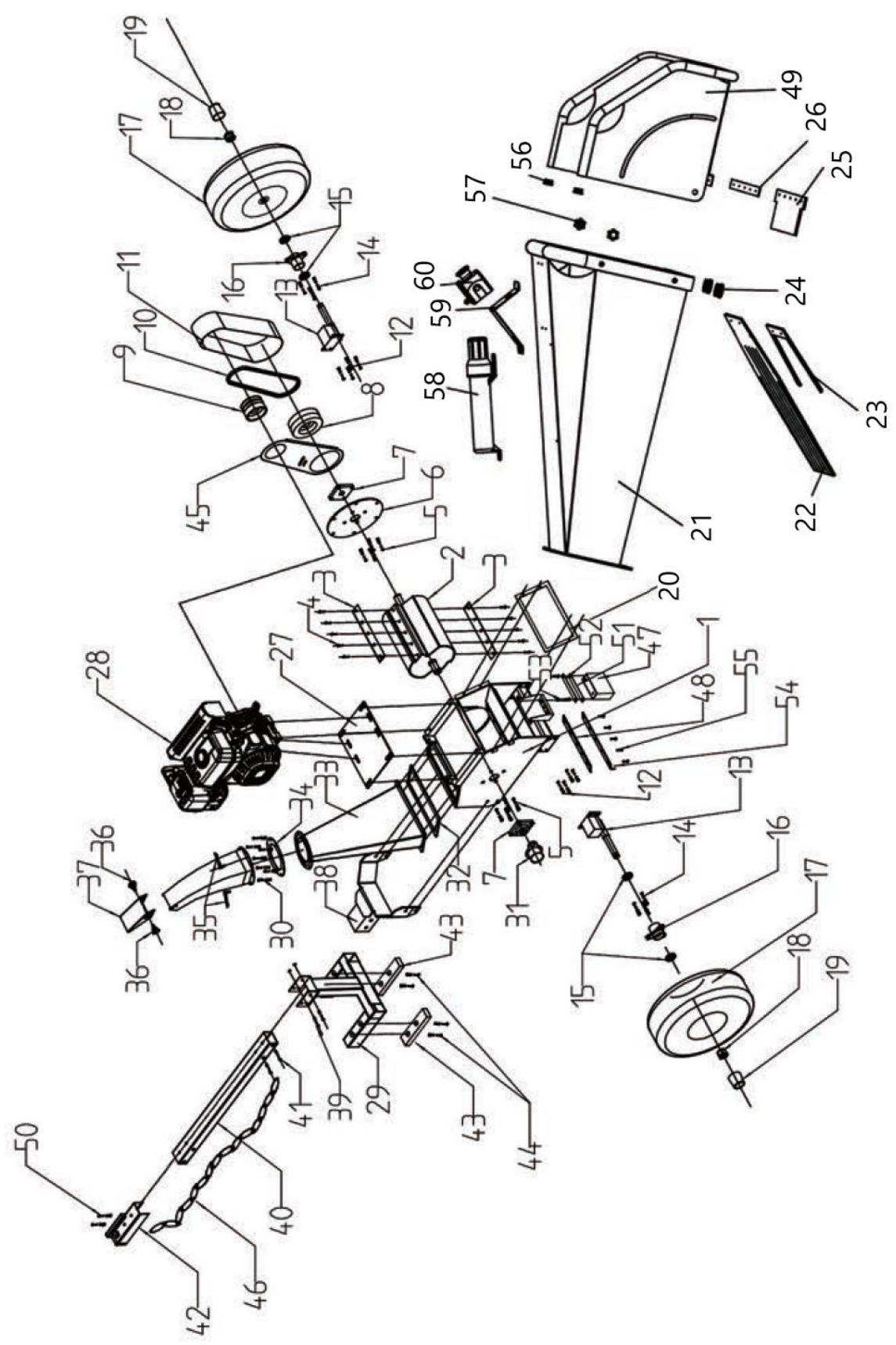
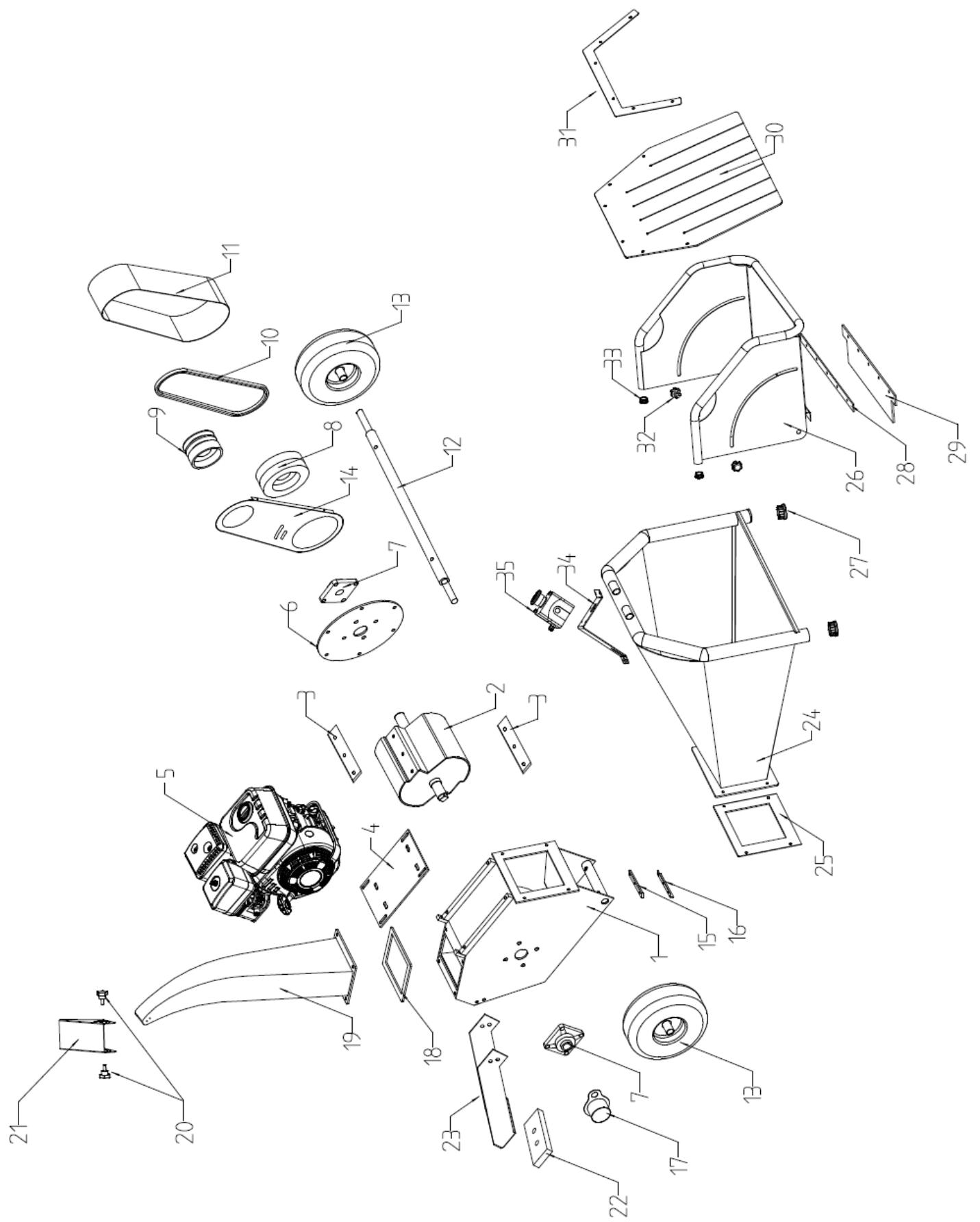
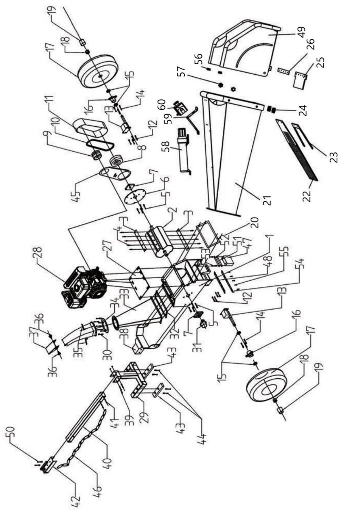
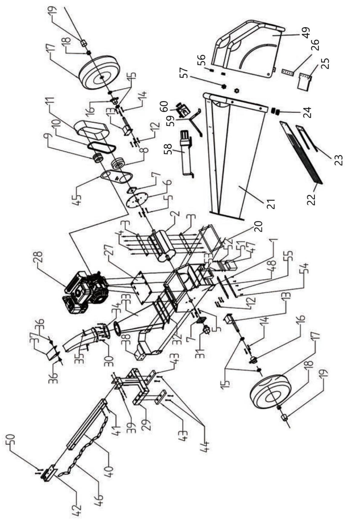
11. Assembly drawings
HT-HECTOR-1200A
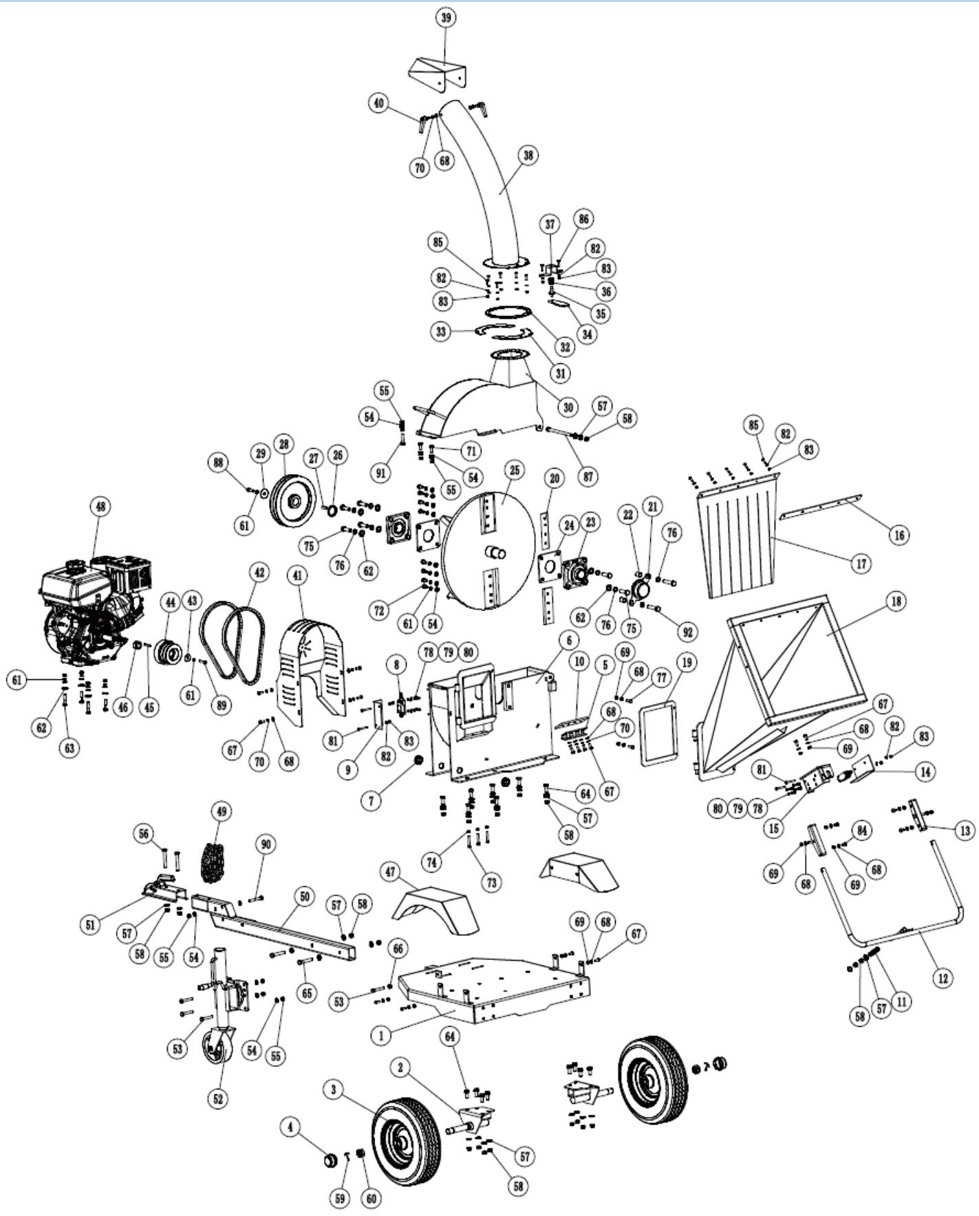
| Number | Description | Quantity | Number | Description | Quantity |
| 1 | Chassis | 1 | 47 | Fenders | 2 |
| 2 | Wheel axle | 2 | 48 | Engine | 1 |
| 3 | Wheel | 2 | 49 | Safety chain | 2 |
| 4 | Dust cover | 2 | 50 | Towbar | 1 |
| 5 | Anvil adjustment plate | 1 | 51 | Connector | 1 |
| 6 | Cutting disc base | 1 | 52 | Wheel | 1 |
| 7 | Protective ring | 2 | 53 | Hexagonal screw M10x60 | 4 |
| 8 | Switch | 2 | 54 | Flat washer 10 | 23 |
| 9 | Switch cover | 1 | 55 | M10 lock nut | 12 |
| 10 | Anvil | 1 | 56 | Hexagonal screw M12x80 | 2 |
| 11 | Spring | 1 | 57 | Flat washer 12 | thirty |
| 12 | Emergency stop lever | 1 | 58 | M12 lock nut | 22 |
| 13 | Stop lever support | 2 | 59 | 4x45 cotter pin | 2 |
| 14 | Switch cover | 1 | 60 | Hexagonal nut M24x1.5 | 2 |
| 15 | Switch base | 1 | 61 | Spring washer 10 | 14 |
| 16 | Rubber mounting plate | 1 | 62 | Flat washer 14 | 10 |
| 17 | Rubber partition | 1 | 63 | Support screw M10x45 | 4 |
| 18 | Loading hopper | 1 | 64 | Hexagonal screw M12x30 | 15 |
| 19 | Feeding rubber to the frame | 1 | 65 | Hexagonal screw M12x70 | 2 |
| 20 | Blades | 2 | 66 | M10 hexagonal nut | 1 |
| 21 | Bearing cover | 1 | 67 | M8x20 hexagonal screw | 14 |
| 22 | Retaining ring | 2 | 68 | Flat washer 8 | 24 |
| 23 | UCFU208 bearing | 2 | 69 | M8 lock nut | 14 |
| 24 | Bearing base | 2 | 70 | Spring washer 8 | 10 |
| 25 | Chipper disk | 1 | 71 | Hexagonal screw M10x25 | 2 |
| 26 | Retaining ring | 1 | 72 | Hexagonal screw M10x20 | 8 |
| 27 | Flat key | 1 | 73 | Hex head screw M8x45 | 3 |
| 28 | Pulley | 1 | 74 | M8 hex nut | 3 |
| 29 | Pulley seal | 1 | 75 | Hexagonal screw M14x45 | 6 |
| thirty | Disk cover | 1 | 76 | Spring washer 14 | 8 |
| 31 | Connection plate 1 | 1 | 77 | M8x25 hex bolt | 2 |
| 32 | Rotating plate | 1 | 78 | M5x12 hex bolt | 8 |
| 33 | Connecting plate 2 | 1 | 79 | Spring washer 5 | 8 |
| 34 | Handle | 1 | 80 | Flat washer 5 | 8 |
| 35 | Handle shaft | 1 | 81 | M6x50 hexagonal screw | 4 |
| 36 | Pad | 1 | 82 | Flat washer 6 | 17 |
| 37 | Handle support | 1 | 83 | M6 lock nut | 17 |
| 38 | Discharge chute | 1 | 84 | M8x16 hex bolt | 4 |
| 39 | Deflector | 1 | 85 | M6x20 hexagonal screw | 11 |
| 40 | Clamping chuck | 2 | 86 | M6x25 hexagonal screw | 2 |
| 41 | Belt cover | 1 | 87 | Hexagonal screw M12x165 | 1 |
| 42 | Belt | 2 | 88 | Hexagonal screw M10x30 | 1 |
| 43 | Clutch seal | 1 | 89 | Hex bolt 3/8-24x1 | 1 |
| 44 | Clutch | 1 | 90 | Hexagonal screw M10x70 | 1 |
| 45 | Open-end wrench for the engine | 1 | 91 | Hexagonal screw M10x45 | 1 |
| 46 | Retaining ring | 1 | 92 | Hexagonal screw M14x65 | 2 |
HT-HECTOR-1200B | HT-HECTOR-1200C

| Number | Description | Quantity | Number | Description | Quantity |
| 1 | Basic frame | 1 | 31 | Bearing cover | 1 |
| 2 | Roller | 1 | 32 | Outlet to frame rubber | 1 |
| 3 | Knife | 2 | 33 | Discharge chute | 1 |
| 4 | Hexagonal screw M10x25 | 8 | 34 | Flange for discharge chute | 1 |
| 5 | Hexagonal screw M12x40 | 12 | 35 | M8x15 handle screw | 2 |
| 6 | Bearing mounting plate | 1 | 36 | M8x15 screw | 2 |
| 7 | Bearing | 2 | 37 | Gutter deflector | 1 |
| 8 | Pulley | 1 | 38 | Foot immobilization | 1 |
| 9 | Clutch | 1 | 39 | Hexagonal screw M10x70 | 2 |
| 10 | Drive belt | 2 | 40 | Towbar | 1 |
| 11 | Belt cover | 1 | 41 | Hexagonal screw M10x60 | 2 |
| 12 | Hexagonal screw M10x25 | 8 | 42 | 2" connector | 1 |
| 13 | Wheel axle | 1 | 43 | Rubber pad | 2 |
| 14 | M8x25 hex bolt | 6 | 44 | Hexagonal screw M8x30 | 4 |
| 15 | Wheel bearing | 2 | 45 | Inner strap plate | 1 |
| 16 | Wheel flange | 2 | 46 | Safety chains | 1 |
| 17 | Tire 16*8.00-7 | 2 | 47 | Battery | 1 |
| 18 | Crown nut M24x1.5 | 2 | 48 | Anvil | 1 |
| 19 | Rubber wheel cover | 2 | 49 | Filling chute B | 1 |
| 20 | Feeding rubber to the frame | 1 | 50 | Hexagonal screw M12x80 | 4 |
| 21 | Food chute A | 1 | 51 | Rubber pad | 1 |
| 22 | Rubber partition | 1 | 52 | Battery cover | 1 |
| 23 | Rubber partition mount | 1 | 53 | M8x20 hexagonal screw | 4 |
| 24 | Pipe plug 038 | 2 | 54 | Anvil mounting plate | 1 |
| 25 | Rubber flap | 1 | 55 | Hexagonal screw M10x25 | 10 |
| 26 | Rubber flap clamp | 1 | 56 | Pipe plug 025 | 2 |
| 27 | Engine base plate | 1 | 57 | M8 star nut | 2 |
| 28 | Engine | 1 | 58 | Hand grip | 1 |
| 29 | Support feet | 1 | 59 | Switch support | 1 |
| thirty | M6x25 hexagonal screw | 8 | 60 | Emergency stop button | 1 |
HT-HECTOR-1000
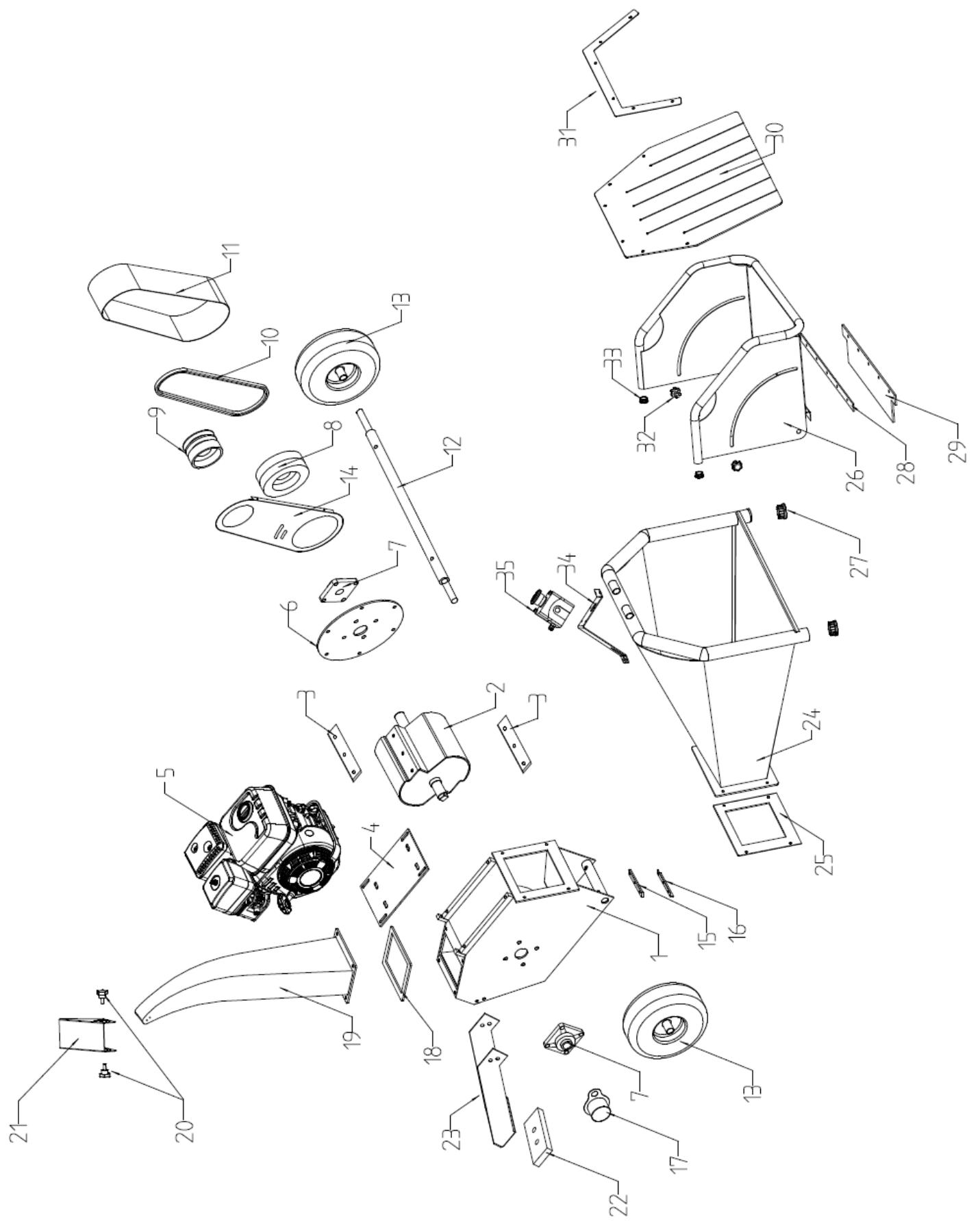
| Number | Description | Number | Description |
| 1 | Device body | 19 | Discharge chute |
| 2 | Roller | 20 | Star screw |
| 3 | Knife | 21 | Gutter deflector |
| 4 | Engine base plate | 22 | Rubber pad |
| 5 | Engine | 23 | Support feet |
| 6 | Bearing mounting plate | 24 | Feed hopper A |
| 7 | Bearing | 25 | Feeding rubber to the frame |
| 8 | Pulley | 26 | B hopper |
| 9 | Clutch | 27 | Pipe plug ∅38 |
| 10 | Drive belt | 28 | Rubber flat clamp |
| 11 | Belt cover | 29 | Flat rubber |
| 12 | Wheel axle | thirty | Rubber partition |
| 13 | Tire | 31 | Rubber partition mount |
| 14 | Inner strap plate | 32 | M8 star nut |
| 15 | Anvil | 33 | Pipe plug ∅25 |
| 16 | Anvil mounting plate | 34 | Change support |
| 17 | Bearing cover | 35 | Emergency stop button |
| 18 | Outlet to frame rubber |

A - tłumik






2) Podpora przednia
Q – zawór paliwa
Ostrzenie ostrzy
HT-HECTOR-1200B | HT-HECTOR-1200C

A - tlumič
B - páka plynu



2) Přední podpora

Q – palivový ventil
P – Páka plynu
4) Nastavte spínač motoru do polohy "ON".
I – Startovací lano
Platí pro model HT-HECTOR-1200B | HT-HECTOR-1200C
Jak udržovat stroj
Ostření nožů
HT-HECTOR-1200B | HT-HECTOR-1200C

A - silencieux
B - la manette des gaz




2) Support avant
Q – robinet de carburant
2) Déplacez le levier de starter en position "FERMÉ".
Affûtage des lames
HT-HECTOR-1200B | HT-HECTOR-1200C
A - silenziatore
I - CANDELA DI ACCENSIONE:





Q – valvola del carburante
Si applica al modello HT-HECTOR-1200B | HT-HECTOR-1200C
HT-HECTOR-1200B | HT-HECTOR-1200C

A - silenciador




2) Soporte frontal
Q – válvula de combustible

| Cantidad | Descripción del dispositivo | Cantidad | Cantidad | Descripción del dispositivo | Cantidad |
| 1 | Chasis | 1 | 47 | Defensas | 2 |
| 2 | Eje de la rueda | 2 | 48 | Motor | 1 |
| 3 | Rueda | 2 | 49 | Cadena de seguridad | 2 |
| 4 | Guardapolvo | 2 | 50 | Enganche de remolque | 1 |
| 5 | Placa de ajuste del yunque | 1 | 51 | Conector | 1 |
| 6 | Base del disco de corte | 1 | 52 | Rueda | 1 |
| 7 | Anillo protector | 2 | 53 | Tornillo hexagonal M10x60 | 4 |
| 8 | Interruptor | 2 | 54 | Arandela plana 10 | 23 |
| 9 | Cubierta del interruptor | 1 | 55 | tuerca de seguridad M10 | 12 |
| 10 | Yunque | 1 | 56 | Tornillo hexagonal M12x80 | 2 |
| 11 | Muelle | 1 | 57 | Arandela plana 12 | treinta |
| 12 | Palanca de parada de emergencia | 1 | 58 | tuerca de seguridad M12 | 22 |
| 13 | Soporte de palanca de parada | 2 | 59 | pasador de chaveta 4x45 | 2 |
| 14 | Cubierta del interruptor | 1 | 60 | Tuerca hexagonal M24x1,5 | 2 |
| 15 | Cambiar base | 1 | 61 | Arandela elástica 10 | 14 |
| 16 | Placa de montaje de goma | 1 | 62 | Arandela plana 14 | 10 |
| 17 | Tabique de goma | 1 | 63 | Tornillo soporte M10x45 | 4 |
| 18 | Tolva de carga | 1 | 64 | Tornillo hexagonal M12x30 | 15 |
| 19 | Alimentando caucho al marco. | 1 | 65 | Tornillo hexagonal M12x70 | 2 |
| 20 | Cuchillas | 2 | 66 | Tuerca hexagonal M10 | 1 |
| 21 | Tapa del cojinete | 1 | 67 | tornillo hexagonal m8x20 | 14 |
| 22 | Anillo de sujeción | 2 | 68 | Arandela plana 8 | 24 |
| 23 | Rodamiento UCFU208 | 2 | 69 | tuerca de seguridad M8 | 14 |
| 24 | Base de rodamiento | 2 | 70 | arandela elástica 8 | 10 |
| 25 | Disco triturador | 1 | 71 | Tornillo hexagonal M10x25 | 2 |
| 26 | Anillo de sujeción | 1 | 72 | Tornillo hexagonal M10x20 | 8 |
| 27 | Ilave plana | 1 | 73 | Tornillo cabeza hexagonal M8x45 | 3 |
| 28 | Rodillo | 1 | 74 | tuerca hexagonal m8 | 3 |
| 29 | Sello de polea | 1 | 75 | Tornillo hexagonal M14x45 | 6 |
| treinta | tapa del disco | 1 | 76 | Arandela elástica 14 | 8 |
| 31 | Placa de conexión 1 | 1 | 77 | Perno hexagonal M8x25 | 2 |
| 32 | Placa giratoria | 1 | 78 | Perno hexagonal M5x12 | 8 |
| 33 | Placa de conexión 2 | 1 | 79 | arandela elástica 5 | 8 |
| 34 | Agarradero | 1 | 80 | Arandela plana 5 | 8 |
| 35 | Eje del mango | 1 | 81 | Tornillo hexagonal M6x50 | 4 |
| 36 | Almohadilla | 1 | 82 | Arandela plana 6 | 17 |
| 37 | Soporte de mango | 1 | 83 | tuerca de seguridad M6 | 17 |
| 38 | Canal de descarga | 1 | 84 | Perno hexagonal M8x16 | 4 |
| 39 | Deflector | 1 | 85 | tornillo hexagonal m6x20 | 11 |
| 40 | mandril de sujeción | 2 | 86 | tornillo hexagonal m6x25 | 2 |
| 41 | Funda para cinturón | 1 | 87 | Tornillo hexagonal M12x165 | 1 |
| 42 | Correa | 2 | 88 | Tornillo hexagonal M10x30 | 1 |
| 43 | Sello de embrague | 1 | 89 | Perno hexagonal 3/8-24x1 | 1 |
| 44 | Embrague | 1 | 90 | Tornillo hexagonal M10x70 | 1 |
| 45 | Llave de boca para el motor. | 1 | 91 | Tornillo hexagonal M10x45 | 1 |
| 46 | Anillo de sujeción | 1 | 92 | Tornillo hexagonal M14x65 | 2 |
HT-HÉCTOR-1200B | HT-HECTOR-1200C


A - hangtompító
B - gázkar





2) Elülső támasz

Q - üzemanyagszelep
P - Gázkar
I - Indítókötél
A pengék élezése
HT-HECTOR-1200B | HT-HECTOR-1200C


A - Lyddæmper
B - Gashåndtag



Montering af modeller: HT-HECTOR-1200B og HT-HECTOR-1200C
Udpakning


2) Støtte foran
Q - brændstofventil
P - Gashåndtag
4) Sæt motorkontakten i positionen "ON".

I - Startsnor
Gælder for model HT-HECTOR-1200B | HT-HECTOR-1200C
Slibning af knivene
HT-HECTOR-1200B | HT-HECTOR-1200C

A - äänenvaimennin
B - kaasuvipu


Mallien kokoonpano: HT-HECTOR-1200B ja HT-HECTOR-1200C
Purkaminen


2) Etutuki

8. Laitteen käyttö
P – Kaasuvipu
I – Käynnistysköysi
Koskee mallia HT-HECTOR-1200B | HT-HECTOR-1200C
Terien teroitus
HT-HECTOR-1200B | HT-HECTOR-1200C


A - geluiddemper
B - gashendel


3) Trekhaakbevestiging


Montage van modellen: HT-HECTOR-1200B en HT-HECTOR-1200C
Uitpakken

2) Voorste steun
Q – brandstofklep
2) Zet de chokehendel in de stand "DICHT".
P – Gashendel
Ik – Starttouw
HT-HECTOR-1200B | HT-HECTOR-1200C
A - lyddemper
B - gasspaken


3) Tilhengerfeste
a) Fest koblingen (47) til trekkstangen (46) med en M12x80 sekskantbolt (52), en 12 flat skive (53) og en M12 låsemutter (54).
b) Fest tilhengerfestet (46) til chassiset (1) med en M12x70 sekskantbolt (61), en 12 flat skive (53) og en M12 läsemutter (54).
c) Fest støttehjulet (48) til draget (46) med M10x60 sekskantbolt (49), flatskive 12 (53) og flatskive 10 (50).



2) Støtte foran

Q – drivstoffventil
P – Gasspak
I – Starttau
Gjelder modell HT-HECTOR-1200B | HT-HECTOR-1200C

Sliping av knivene
| Antall | Beskrivelse | Antall | Antall | Beskrivelse | Antall |
| 1 | Chassis | 1 | 47 | Fendere | 2 |
| 2 | Hjulaksel | 2 | 48 | Motor | 1 |
| 3 | Hjul | 2 | 49 | Sikkerhetskjede | 2 |
| 4 | Støvdeksel | 2 | 50 | Tilhengerfeste | 1 |
| 5 | Ambolt justeringsplate | 1 | 51 | Kobling | 1 |
| 6 | Skjæreskivebase | 1 | 52 | Hjul | 1 |
| 7 | Beskyttelsesring | 2 | 53 | Sekskantskrue M10x60 | 4 |
| 8 | Bytte om | 2 | 54 | Flat skive 10 | 23 |
| 9 | Bryterdeksel | 1 | 55 | M10 låsemutter | 12 |
| 10 | Ambolt | 1 | 56 | Sekskantskrue M12x80 | 2 |
| 11 | Fjær | 1 | 57 | Flat skive 12 | tretti |
| 12 | Nødstoppspak | 1 | 58 | M12 låsemutter | 22 |
| 13 | Stoppspakstøtte | 2 | 59 | 4x45 splint | 2 |
| 14 | Bryterdeksel | 1 | 60 | Sekskantmutter M24x1,5 | 2 |
| 15 | Bytt base | 1 | 61 | Fjærskive 10 | 14 |
| 16 | Gummi monteringsplate | 1 | 62 | Flat skive 14 | 10 |
| 17 | Gummi skillevegg | 1 | 63 | Støtteskrue M10x45 | 4 |
| 18 | Lastebeholder | 1 | 64 | Sekskantskrue M12x30 | 15 |
| 19 | Mater gummi til rammen | 1 | 65 | Sekskantskrue M12x70 | 2 |
| 20 | Blader | 2 | 66 | M10 sekskantmutter | 1 |
| 21 | Lagerdeksel | 1 | 67 | M8x20 sekskantskrue | 14 |
| 22 | Holdering | 2 | 68 | Flat skive 8 | 24 |
| 23 | UCFU208 lager | 2 | 69 | M8 låsemutter | 14 |
| 24 | Lagerbase | 2 | 70 | Fjærskive 8 | 10 |
| 25 | Chipper disk | 1 | 71 | Sekskantskrue M10x25 | 2 |
| 26 | Holdering | 1 | 72 | Sekskantskrue M10x20 | 8 |
| 27 | Flat nøkkel | 1 | 73 | Sekskantskrue M8x45 | 3 |
| 28 | Talje | 1 | 74 | M8 sekskantmutter | 3 |
| 29 | Remskive tetning | 1 | 75 | Sekskantskrue M14x45 | 6 |
| tretti | Diskdeksel | 1 | 76 | Fjærskive 14 | 8 |
| 31 | Tilkoblingsplate 1 | 1 | 77 | M8x25 sekskantbolt | 2 |
| 32 | Roterende plate | 1 | 78 | M5x12 sekskantbolt | 8 |
| 33 | Koblingsplate 2 | 1 | 79 | Fjærskive 5 | 8 |
| 34 | Håndtak | 1 | 80 | Flat skive 5 | 8 |
| 35 | Håndtaksskaft | 1 | 81 | M6x50 sekskantskrue | 4 |
| 36 | Pad | 1 | 82 | Flat skive 6 | 17 |
| 37 | Håndtaksstøtte | 1 | 83 | M6 låsemutter | 17 |
| 38 | Utløpsrenne | 1 | 84 | M8x16 sekskantbolt | 4 |
| 39 | Deflektor | 1 | 85 | M6x20 sekskantskrue | 11 |
| 40 | Spennende chuck | 2 | 86 | M6x25 sekskantskrue | 2 |
| 41 | Beltetrekk | 1 | 87 | Sekskantskrue M12x165 | 1 |
| 42 | Reim | 2 | 88 | Sekskantskrue M10x30 | 1 |
| 43 | Clutchpakning | 1 | 89 | Sekskantbolt 3/8-24x1 | 1 |
| 44 | Kopling | 1 | 90 | Sekskantskrue M10x70 | 1 |
| 45 | Åpennøkkel for motoren | 1 | 91 | Sekskantskrue M10x45 | 1 |
| 46 | Holdering | 1 | 92 | Sekskantskrue M14x65 | 2 |
HT-HECTOR-1200B | HT-HECTOR-1200C

| Antall | Beskrivelse | Antall | Antall | Beskrivelse | Antall |
| 1 | Grunnramme | 1 | 31 | Lagerdeksel | 1 |
| 2 | Aksel | 1 | 32 | Uttak til rammegummi | 1 |
| 3 | Kniv | 2 | 33 | Utløpsrenne | 1 |
| 4 | Sekskantskrue M10x25 | 8 | 34 | Flens for utløpsrenne | 1 |
| 5 | Sekskantskrue M12x40 | 12 | 35 | M8x15 håndtaksskrue | 2 |
| 6 | Lagermonteringsplate | 1 | 36 | M8x15 skrue | 2 |
| 7 | Peiling | 2 | 37 | Renneavviser | 1 |
| 8 | Talje | 1 | 38 | Immobilisering av foten | 1 |
| 9 | Kopling | 1 | 39 | Sekskantskrue M10x70 | 2 |
| 10 | Drivreim | 2 | 40 | Tilhengerfeste | 1 |
| 11 | Beltetrekk | 1 | 41 | Sekskantskrue M10x60 | 2 |
| 12 | Sekskantskrue M10x25 | 8 | 42 | 2" kontakt | 1 |
| 13 | Hjulaksel | 1 | 43 | Gummipute | 2 |
| 14 | M8x25 sekskantbolt | 6 | 44 | Sekskantskrue M8x30 | 4 |
| 15 | Hjullager | 2 | 45 | Innvendig stroppplate | 1 |
| 16 | Hjulflens | 2 | 46 | Sikkerhetskjeder | 1 |
| 17 | Dekk 16*8,00-7 | 2 | 47 | Batteri | 1 |
| 18 | Kronemutter M24x1,5 | 2 | 48 | Ambolt | 1 |
| 19 | Gummi hjuldeksel | 2 | 49 | Påfyllingsrenne B | 1 |
| 20 | Mater gummi til rammen | 1 | 50 | Sekskantskrue M12x80 | 4 |
| 21 | Matrenne A | 1 | 51 | Gummipute | 1 |
| 22 | Gummi skillevegg | 1 | 52 | Batterideksel | 1 |
| 23 | Gummi festevegg | 1 | 53 | M8x20 sekskantskrue | 4 |
| 24 | Rørplugg 038 | 2 | 54 | Ambolt monteringsplate | 1 |
| 25 | Gummi klaff | 1 | 55 | Sekskantskrue M10x25 | 10 |
| 26 | Klaffklemme av gummi | 1 | 56 | Rørplugg 025 | 2 |
| 27 | Motorbunnplate | 1 | 57 | M8 stjernemutter | 2 |
| 28 | Motor | 1 | 58 | Håndgrep | 1 |
| 29 | Støtteføtter | 1 | 59 | Bryterstøtte | 1 |
| tretti | M6x25 sekskantskrue | 8 | 60 | Nødstoppknapp | 1 |
HT-HECTOR-1000
OBS! Brandrisk – brandfarliga material!

A - ljuddämpare
B - Gasreglage


3) Dragkrokfäste




2) Främre stöd
3) Installation av utloppsrännan
Q – bränsleventil
P – Gasreglage
I – Startrep
Gäller modell HT-HECTOR-1200B | HT-HECTOR-1200C
| siffra | Beskrivning | Antal | siffra | Beskrivning | Antal |
| 1 | Chassi | 1 | 47 | Stänkskärmar | 2 |
| 2 | Hjulaxel | 2 | 48 | Motor | 1 |
| 3 | Hjul | 2 | 49 | Säkerhetskedja | 2 |
| 4 | Dammskydd | 2 | 50 | Dragkrok | 1 |
| 5 | Städjusteringsplatta | 1 | 51 | Koppling | 1 |
| 6 | Skärskivans bas | 1 | 52 | Hjul | 1 |
| 7 | Skyddsring | 2 | 53 | Sexkantskruv M10x60 | 4 |
| 8 | Växla | 2 | 54 | Platt bricka 10 | 23 |
| 9 | Brytarkåpa | 1 | 55 | M10 låsmutter | 12 |
| 10 | Städ | 1 | 56 | Sexkantskruv M12x80 | 2 |
| 11 | Fjäder | 1 | 57 | Platt bricka 12 | trettio |
| 12 | Nödstoppsspak | 1 | 58 | M12 låsmutter | 22 |
| 13 | Stoppspaksstöd | 2 | 59 | 4x45 sax | 2 |
| 14 | Brytarkåpa | 1 | 60 | Sexkantsmutter M24x1,5 | 2 |
| 15 | Byt bas | 1 | 61 | Fjäderbricka 10 | 14 |
| 16 | Gummi monteringsplatta | 1 | 62 | Platt bricka 14 | 10 |
| 17 | Gummivägg | 1 | 63 | Stödskruv M10x45 | 4 |
| 18 | Laddar tratt | 1 | 64 | Sexkantskruv M12x30 | 15 |
| 19 | Matar gummi till ramen | 1 | 65 | Sexkantskruv M12x70 | 2 |
| 20 | Blad | 2 | 66 | M10 sexkantsmutter | 1 |
| 21 | Lagerskydd | 1 | 67 | M8x20 sexkantsskruv | 14 |
| 22 | Låsring | 2 | 68 | Platt bricka 8 | 24 |
| 23 | UCFU208 lager | 2 | 69 | M8 låsmutter | 14 |
| 24 | Lagerbas | 2 | 70 | Fjäderbricka 8 | 10 |
| 25 | Flisskiva | 1 | 71 | Sexkantskruv M10x25 | 2 |
| 26 | Låsring | 1 | 72 | Sexkantskruv M10x20 | 8 |
| 27 | Platt nyckel | 1 | 73 | Sexkantskruv M8x45 | 3 |
| 28 | Remskiva | 1 | 74 | M8 sexkantsmutter | 3 |
| 29 | Remskiva tätning | 1 | 75 | Sexkantskruv M14x45 | 6 |
| trettio | Diskskydd | 1 | 76 | Fjäderbricka 14 | 8 |
| 31 | Anslutningsplatta 1 | 1 | 77 | M8x25 sexkantsbult | 2 |
| 32 | Roterande platta | 1 | 78 | M5x12 sexkantsbult | 8 |
| 33 | Anslutningsplatta 2 | 1 | 79 | Fjäderbricka 5 | 8 |
| 34 | Handtag | 1 | 80 | Platt bricka 5 | 8 |
| 35 | Handtagsskaft | 1 | 81 | M6x50 sexkantsskruv | 4 |
| 36 | Vaddera | 1 | 82 | Platt bricka 6 | 17 |
| 37 | Handtagsstöd | 1 | 83 | M6 låsmutter | 17 |
| 38 | Utloppsränna | 1 | 84 | M8x16 sexkantsbult | 4 |
| 39 | Deflektor | 1 | 85 | M6x20 sexkantsskruv | 11 |
| 40 | Spännchuck | 2 | 86 | M6x25 sexkantsskruv | 2 |
| 41 | Bältesskydd | 1 | 87 | Sexkantskruv M12x165 | 1 |
| 42 | Rem | 2 | 88 | Sexkantskruv M10x30 | 1 |
| 43 | Kopplingstätning | 1 | 89 | Sexkantsbult 3/8-24x1 | 1 |
| 44 | Koppling | 1 | 90 | Sexkantskruv M10x70 | 1 |
| 45 | Öppen skiftnyckel för motorn | 1 | 91 | Sexkantskruv M10x45 | 1 |
| 46 | Låsring | 1 | 92 | Sexkantskruv M14x65 | 2 |
HT-HECTOR-1200B | HT-HECTOR-1200C

A - silenciador
B - alavanca do acelerador




2) Suporte frontal
P – Alavanca do acelerador
I – Corda de partida
Afiando as lâminas
HT-HECTOR-1200B | HT-HECTOR-1200C


A - tlmič
B - páka plynu


3) Upevnenie na t'ažné zariadenie
a) Pripevnite spojku (47) k oji (46) pomocou šesthrannej skrutky M12x80 (52), 12 plochej podložky (53) a poistnej matice M12 (54).
b) Pripevnite tažné zariadenie (46) k podvozku (1) pomocou šesthrannej skrutky M12x70 (61), 12 plochej podložky (53) a poistnej matice M12 (54).



b) Nakloňte kryt čepele mierne dozadu a pripevnite osku skrutkami, podložkami a maticami.
2) Predná podpora

Q – palivový ventil
2) Presuňte páčku sýtiča do polohy "ZATVORENÉ".
P – Páčka plynu
4) Nastavte spínač motora do polohy "ON".

I – Štartovacie lano
Platí pre model HT-HECTOR-1200B | HT-HECTOR-1200C
Ako udržiavať stroj

Ostrenie čepelí
| číslo | Popis | Množstvo | číslo | Popis | Množstvo |
| 1 | Podvozok | 1 | 47 | Blatníky | 2 |
| 2 | Os kolesa | 2 | 48 | Motor | 1 |
| 3 | Koleso | 2 | 49 | Bezpečnostná retáz | 2 |
| 4 | Prachový kryt | 2 | 50 | Čažné zariadenie | 1 |
| 5 | Doska na nastavenie kovadliny | 1 | 51 | Konektor | 1 |
| 6 | Základňa rezného kotúča | 1 | 52 | Koleso | 1 |
| 7 | Ochranný krůžok | 2 | 53 | Šesthranná skrutka M10x60 | 4 |
| 8 | Prepínač | 2 | 54 | Plochá podložka 10 | 23 |
| 9 | Kryt spínača | 1 | 55 | Poistná matica M10 | 12 |
| 10 | Nákova | 1 | 56 | Šesthranná skrutka M12x80 | 2 |
| 11 | Jar | 1 | 57 | Plochá podložka 12 | tridsat' |
| 12 | Páčka núdzového zastavenia | 1 | 58 | Poistná matica M12 | 22 |
| 13 | Podpora páky dorazu | 2 | 59 | Závlačka 4x45 | 2 |
| 14 | Kryt spínača | 1 | 60 | Šesthranná matica M24x1,5 | 2 |
| 15 | Spínacia základňa | 1 | 61 | Pružinová podložka 10 | 14 |
| 16 | Gumová montážna doska | 1 | 62 | Plochá podložka 14 | 10 |
| 17 | Gumená priečka | 1 | 63 | Nosná skrutka M10x45 | 4 |
| 18 | Nakladacia násypka | 1 | 64 | Šesthranná skrutka M12x30 | 15 |
| 19 | Prívod gumy do rámu | 1 | 65 | Šesthranná skrutka M12x70 | 2 |
| 20 | Čepele | 2 | 66 | Šesthranná matica M10 | 1 |
| 21 | Kryt ložiska | 1 | 67 | Šesthranná skrutka M8x20 | 14 |
| 22 | Poistný krůžok | 2 | 68 | Plochá podložka 8 | 24 |
| 23 | Ložisko UCFU208 | 2 | 69 | Poistná matica M8 | 14 |
| 24 | Ložisková základňa | 2 | 70 | Pružinová podložka 8 | 10 |
| 25 | Štiepkovací disk | 1 | 71 | Šesthranná skrutka M10x25 | 2 |
| 26 | Poistný krůžok | 1 | 72 | Šesthranná skrutka M10x20 | 8 |
| 27 | Plochý klůč | 1 | 73 | Šesthranná skrutka M8x45 | 3 |
| 28 | Kladka | 1 | 74 | Šesthranná matica M8 | 3 |
| 29 | Tesnenie kladky | 1 | 75 | Šesthranná skrutka M14x45 | 6 |
| tridsat' | Kryt disku | 1 | 76 | Pružinová podložka 14 | 8 |
| 31 | Spojovacia doska 1 | 1 | 77 | Šesthranná skrutka M8x25 | 2 |
| 32 | Otočný tanier | 1 | 78 | Šesthranná skrutka M5x12 | 8 |
| 33 | Spojovacia doska 2 | 1 | 79 | Pružinová podložka 5 | 8 |
| 34 | Rukovát' | 1 | 80 | Plochá podložka 5 | 8 |
| 35 | Hriadel' rukoväte | 1 | 81 | Šesthranná skrutka M6x50 | 4 |
| 36 | Pad | 1 | 82 | Plochá podložka 6 | 17 |
| 37 | Podpora rukoväte | 1 | 83 | Poistná matica M6 | 17 |
| 38 | Vypúšťací žľab | 1 | 84 | Šesthranná skrutka M8x16 | 4 |
| 39 | Deflektor | 1 | 85 | Šesthranná skrutka M6x20 | 11 |
| 40 | Upínacie sklúčovadlo | 2 | 86 | Šesthranná skrutka M6x25 | 2 |
| 41 | Kryt na opasok | 1 | 87 | Šesthranná skrutka M12x165 | 1 |
| 42 | Opasok | 2 | 88 | Šesthranná skrutka M10x30 | 1 |
| 43 | Tesnenie spojky | 1 | 89 | Šesthranná skrutka 3/8-24x1 | 1 |
| 44 | Spojka | 1 | 90 | Šesthranná skrutka M10x70 | 1 |
| 45 | Otvorený klůč na motor | 1 | 91 | Šesthranná skrutka M10x45 | 1 |
| 46 | Poistný krůžok | 1 | 92 | Šesthranná skrutka M14x65 | 2 |
HT-HECTOR-1200B | HT-HECTOR-1200C
For the disposal of the device please consider and act according to the national and local rules and regulations.
CONTACT
expondo Polska sp. z o.o. sp. k.




- WOOD CHIPPER
- VORDERE STÜTZE
- HT-HECTOR-1200B | HT-HECTOR-1200C
- OVERALL DESCRIPTION
- EXPLANATION OF SYMBOLS
- SAFETY OF USE A
- ATTENTION
- SAFETY IN THE WORKPLACE
- PERSONAL SECURITY
- SAFE USE OF THE DEVICE
- THE SCOPE OF APPLICATION OF THE DEVICE
- DEVICE DESCRIPTION
- ENGINE DESCRIPTION
- PREPARATION TO WORK
- DEVICE LOCATION
- WORKING CONDITIONS
- OPERATOR ZONE
- INSTALLATION OF DEVICES
- INSTALLATION OF THE HT-HECTOR-1200A MODEL
- UNPACKING
- FITTING THE WHEELS
- INSTALLATION OF THE FEED HOPPER
- TOWING HITCH ATTACHMENT
- MOUNTING THE DISCHARGE CHUTE
- ASSEMBLY OF MODELS: HT-HECTOR-1200B AND HT-HECTOR-1200C
- WHEELS
- FRONT SUPPORT
- INSTALLATION OF THE DISCHARGE CHUTE
- INSTALLATION OF THE LOADING CHUTE
- CONNECTING THE SAFETY SWITCH
- WORKING WITH THE DEVICE
- TIPS FOR CORRECT USE
- OIL
- CHECKING AND ADDING OIL
- OIL FILLING PROCEDURE
- OIL CHECKING PROCEDURE
- FUEL
- ADDING FUEL
- STARTING AND STOPPING
- STARTING THE ENGINE
- ENGINE SPEED CONTROL
- ENGINE STOP
- SHREDDING
- USAGE INSTRUCTIONS
- IMPORTANT NOTES
- PROCESSING TREES AND BRANCHES WITH A DIAMETER OF 12 CM (5") OR SMALLER
- ADDITIONAL REMARKS
- THIS DAMAGE CAN BE COSTLY AND IS NOT COVERED BY WARRANTY. FOR THIS REASON, IT IS IMPORTANT TO TURN OFF THE MACHINE IMMEDIATELY IF IT JAMS
- REMOVING A BLOCKAGE
- CLEANING AND MAINTENANCE
- APPLIES TO THE HT-HECTOR-1200A MODEL
- HOW TO MAINTAIN THE MACHINE
- DISASSEMBLING THE KNIFE
- SHARPENING THE BLADES
- STRAP ADJUSTMENT
- REPLACING THE BELT
- APPLIES TO MODEL HT-HECTOR-1200B | HT-HECTOR-1200C
- KNIFE REPLACEMENT
- APPLIES TO ALL MODELS
- CENTRIFUGAL CLUTCH TECHNICAL TIPS
- CLUTCH MAINTENANCE
- CLUTCH DISASSEMBLY
- INSTALLING A NEW CLUTCH
- GENERAL RECOMMENDATIONS FOR CLEANING AND STORAGE
- DISPOSAL OF USED DEVICES
- TROUBLESHOOTING
- WARNING
- ASSEMBLY DRAWINGS
- HT-HECTOR-1200A
- HT-HECTOR-1000
- PODPORA PRZEDNIA
- OSTRZENIE OSTRZY
- PŘEDNÍ PODPORA
- PLATÍ PRO MODEL HT-HECTOR-1200B | HT-HECTOR-1200C
- JAK UDRŽOVAT STROJ
- OSTŘENÍ NOŽŮ
- SUPPORT AVANT
- AFFÛTAGE DES LAMES
- SI APPLICA AL MODELLO HT-HECTOR-1200B | HT-HECTOR-1200C
- SOPORTE FRONTAL
- HT-HÉCTOR-1200B | HT-HECTOR-1200C
- ELÜLSŐ TÁMASZ
- A PENGÉK ÉLEZÉSE
- MONTERING AF MODELLER: HT-HECTOR-1200B OG HT-HECTOR-1200C
- UDPAKNING
- STØTTE FORAN
- GÆLDER FOR MODEL HT-HECTOR-1200B | HT-HECTOR-1200C
- SLIBNING AF KNIVENE
- MALLIEN KOKOONPANO: HT-HECTOR-1200B JA HT-HECTOR-1200C
- PURKAMINEN
- ETUTUKI
- LAITTEEN KÄYTTÖ
- KOSKEE MALLIA HT-HECTOR-1200B | HT-HECTOR-1200C
- TERIEN TEROITUS
- TREKHAAKBEVESTIGING
- MONTAGE VAN MODELLEN: HT-HECTOR-1200B EN HT-HECTOR-1200C
- UITPAKKEN
- VOORSTE STEUN
- TILHENGERFESTE
- GJELDER MODELL HT-HECTOR-1200B | HT-HECTOR-1200C
- SLIPING AV KNIVENE
- DRAGKROKFÄSTE
- FRÄMRE STÖD
- INSTALLATION AV UTLOPPSRÄNNAN
- GÄLLER MODELL HT-HECTOR-1200B | HT-HECTOR-1200C
- SUPORTE FRONTAL
- AFIANDO AS LÂMINAS
- UPEVNENIE NA T'AŽNÉ ZARIADENIE
- PREDNÁ PODPORA
- PLATÍ PRE MODEL HT-HECTOR-1200B | HT-HECTOR-1200C
- AKO UDRŽIAVAŤ STROJ
- OSTRENIE ČEPELÍ
- CONTACT
Brand : Hillvert
Model : HT-HECTOR-1200A
Category : Washing machine