
HT-GLS-01 - Washing machine Hillvert - Free user manual and instructions
Find the device manual for free HT-GLS-01 Hillvert in PDF.


| Product type | Petrol log splitter |
| Brand | Hillvert |
| Model | HT-GLS-01 |
| Main functions | Splitting logs by hydraulic cylinder |
| Engine | Single-cylinder 4-stroke OHV, 212 cc, air-cooled |
| Maximum power | 4.1 kW at 3600 rpm |
| Maximum torque | 12 Nm at 2500 rpm |
| Fuel | Unleaded petrol 93 RON (≤E10) |
| Fuel tank capacity | 3.6 L |
| Engine oil | API SE+ 10W30 (5W30 in cold weather) |
| Hydraulic fluid | AW-SAE 10W (capacity 35 L) |
| Maximum splitting force | 22 tonnes |
| Maximum hydraulic pressure | 21 MPa |
| Dimensions (L × D × H) | 1060 × 2200 × 1800 mm |
| Net weight | 220 kg |
| Starting | Recoil / electric (12V battery ≥18 Ah) |
| Protection rating | IP20 |
| Working positions | Horizontal and vertical beam with locking |
| Safety | Lockout switch, low oil protection, emergency stop |
| Spare parts | Engine, pump, cylinder, hoses, filters, spark plug |
| Maintenance | Check oil, air filter, spark plug, hydraulic fluid |
Frequently Asked Questions - HT-GLS-01 Hillvert
User questions about HT-GLS-01 Hillvert
0 question about this device. Answer the ones you know or ask your own.
Ask a new question about this device
Download the instructions for your Washing machine in PDF format for free! Find your manual HT-GLS-01 - Hillvert and take your electronic device back in hand. On this page are published all the documents necessary for the use of your device. HT-GLS-01 by Hillvert.
USER MANUAL HT-GLS-01 Hillvert
A - Steuerhebel
This User Manual has been translated using machine translation. We have made every effort to ensure the translation is accurate, but please note that automated translations are not perfect and are not meant to replace human translators. The official version of the User Manual is in English. Any differences between the translated version and the original English are not legally binding. If you have any questions about the accuracy of the translation, please refer to the English version, which is the official reference. More language versions are available upon request via info@expondo.com.
Technical data
| Parameter description | Parameter value | ||
| Product name | Gasoline log splitter | ||
| Model | HT-GLS-01 | HT-GLS-02 | |
| Engine type | R210Naturally aspirated 1 cylinder OHV 4-stroke air cooled 212 ccm | ||
| Max power [kW] | 4.1 at 3600 rpm | ||
| Max torque [Nm] | 12 at 2500 rpm | ||
| Fuel type | Unleaded gasoline min. 93 octane (RON) ≤E10 | ||
| Engine oil | Type | Standard ambient working conditions:API SE +higher 10W30 (with cleaning additives) | |
| Cold ambient working conditions (not exceeding 0 °C):API SE +higher 5W30 (with cleaning additives) | |||
| Capacity | 0.6 | ||
| Spark plug | Type | F6RTC/ F6TC/ F7RTC/ F7TC/ BP6ES(or equivalent) | |
| Electrode gap [mm] | 0.70-0.80 | ||
| Valve clearance (cold)[mm] | Intake | 0.10-0.15 | |
| Exhaust | 0.15-0.20 | ||
| Fuel tank capacity [L] | 3.6 | ||
| Hydraulic fluid | Type | AW SAE 10W | |
| Capacity [L] | 35 | ||
| Starter | Recoil / Electric | ||
| Battery | 12V ≥18 Ah | ||
| IP protection rating | IP20 | ||
| Dimensions [width x depth x height; mm] | 1060 x 2200 x 1800 | ||
| Weight (netto) [kg] | 220 | 228 | |
| Max splitting force [T] | 22 | 26 | |
| Max hydraulic pressure [MPa] | 21 | ||
| Ram size [inch] | 4 | 4.5 | |
| Max log dimensions | Length [cm] | 55-61 | |
| Diameter [cm] | ∅15-50 | ||
This gasoline powered mechanical appliance is designed to split large logs into smaller pieces for firewood or other purposes. It uses hydraulic pressure to drive a wedge through the log, effectively splitting it with minimal physical effort. The machine is semi-mobile, i.e. it can be towed by a vehicle, but only off-public roads and at speeds not exceeding 70 km/h.
The user is liable for any damage resulting from unintended use of the device.

| 1 | Tow ball | 42 | Pump inlet hose | |
| 2 | Chain | 43 | Inlet hose connector | |
| 3 | Tow bar | 44 | Ram pin | |
| 4 | Pump outlet hose | 45 | Washer | |
| 5 | Cotter pin | 46 | Right rod | |
| 6 | Tow bar pin | 47 | 1/2 connector | |
| 7 | Return hose | 48 | Ram | |
| 8 | Mud guard (left) | 49 | Straight connector | |
| 9 | Tank cap | 50 | Restore pipe | |
| 10 | O-sealing | 51 | Right connector | |
| 11 | Hydraulic filter | 52 | Blade | |
| 12 | Tank circle seal | 53 | Blade fixation | |
| 13 | Tank cover | 54 | Beam | |
| 14 | Tank rect seal | 55 | Spring | |
| 15 | Mud guard (right) | 56 | Rod | |
| 16 | Right rotate rod | 57 | Washer | |
| 17 | M8x50 bolt | 58 | Wheel | |
| 18 | Beam support | 59 | Plug | |
| 19 | Tow bar fixation | 60 | Tank | |
| 20 | Latch | 61 | Spacer | |
| 21 | Beam support fixation | 62 | Slip plate | |
| 22 | Valve pin | 63 | Washer | |
| 23 | Beam handle | 64 | Spacer | |
| 24 | Valve | 65 | Left protector | |
| 25 | M24 slot nut | 66 | Adjustable plate | |
| 26 | Wheel cover | 67 | M6x50 ring | |
| 27 | 8x50 pin | 68 | Spring | |
| 28 | 8x33 pin | 69 | Support foot | |
| 29 | Active rod top fasten plate | 70 | Left board | |
| 30 | Spring washer | 71 | Switch | |
| 31 | Spring | 72 | Switch plate | |
| 32 | Roller | 73 | Ram bottom hose | |
| 33 | Valve rod | 74 | Ram top hose | |
| 34 | Engine | 75 | Safety pipe | |
| 35 | Restore rod | 76 | Ram hoop | |
| 36 | Connector frame | 77 | M8x40 bolt | |
| 37 | Coupler cover | 78 | M12x55 bolt | |
| 38 | Engine coupler | 79 | Blade | |
| 39 | Plum plastic damper | 80 | M12x80 bolt | |
| 40 | Pump coupler | 81 | Blade fitting plate | |
| 41 | Pump | 82 | Spacing plate |

a) Air filter housing
b) Fuel tank cap
c) Fuel tank
d) Muffler with guard
e) Spark plug with wire booth
f) Throttle lever
g) Choke lever
h) Fuel cock
i) Carburettor
j) Recoil starter
k) Recoil starter handle
I) Ignition switch
m) Oil protector
n) Engine oil dipstick
o) Engine oil drain plug
p) Oil (filling) plug
Installation
Unpacking from Crate:
- Pry top, sides, and ends off the pallet. Set panels aside to avoid tire puncture or personal injury.
- Remove any loose parts if included with unit (i.e., operator's manual, etc.)

| 1 | Engine | 8 | Pump | |
| 2 | Log holder | 9 | Vertical holder | |
| 2 | Wheel | 10 | Protect pipe | |
| 4 | Tank | 11 | Beam | |
| 5 | Mud guard | 12 | Hoses | |
| 6 | Tow bar | 13 | Forefoot | |
| 7 | Tow bar clamp | 14 | Switch plate |
Before assembling:
Disconnect spark plug wire and ground against the engine to prevent unintended starting of the log splitter. To locate the spark plug - please refer to the engine description.
Beam assembling:
- Assemble the both handle (15) to the beam (1) if they are not equipped when unpacking.
- Assemble both log holder (3) to the beam with fitting plate (16), and hook spring (4) with the beam.
- Assemble both protect pipe (2) to the beam with the hardware (5-8).
- If the two control handles (9) are not toward outside, remove and correct both of them.
- Fix the towbar clamp (10) to the beam with the hardware (11-14).

| 1 | Beam | 10 | Tow bar clamp | |
| 2 | Protect pipe | 11 | M10x35 hex bolt | |
| 3 | Log holder | 12 | M10 flat washer | |
| 4 | Spring | 13 | M10 flat washer | |
| 5 | M8x45 hex bolt | 14 | M10 spring washer | |
| 6 | M8 flat washer | 15 | M10 lock nut | |
| 7 | M8 spring washer | 16 | Handle | |
| 8 | M8 lock nut | 17 | Fitting plate | |
| 9 | Control handle | M10x35 hardware |
Towbar assembling:
- Insert beam pin (5) through center base (4), towbar (2) and then insert the cotter pin (6) to the beam pin.
- Assemble the forefoot (3) to the towbar with bolt (8) through the top hole and pin set (7) to the bottom hole.
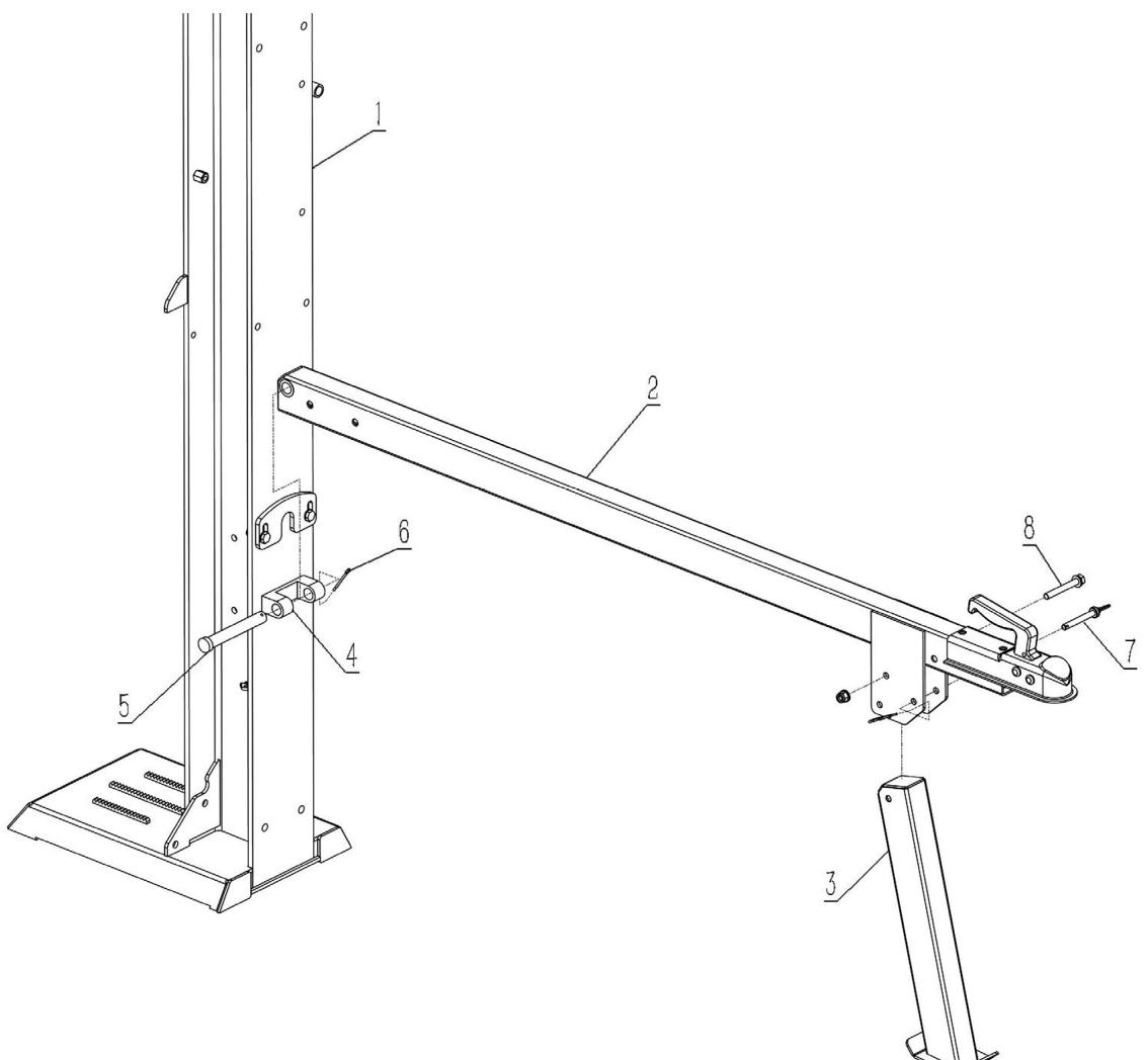
| 1 | Beam | 5 | Beam pin | |
| 2 | Tow bar | 6 | Cotter pin | |
| 3 | Forefoot | 7 | M10x70 pin set | |
| 4 | Center base | 8 | M10x80 bolt |
Hydraulic fluid tank assembling:
- Assemble both mud guard (6) to the tank (1) and fasten with the M8 hardware (7-10).
- Attach to the tank axle in sequence with big washer (11), wheel (2), axle washer (11) and then fasten with slotted nut (4), insert the pin (3) to the axle hole and split the pin to prevent it from falling out, attach the cap (5) to the wheel.

| 1 | Tank | 7 | M8x20 bolt | |
| 2 | Wheel | 8 | M8 flat washer | |
| 3 | Cotter pin | 9 | M8 spring washer | |
| 4 | Slotted unit | 10 | M8 lock nut | |
| 5 | Cap | 11 | Big washer | |
| 6 | Mud guard |
Tank connection:
- Insert the two bolt (5) through hook plate (5), tank, towbar (1), switch plate (6) and then fasten with lock nut.
- Hook the vertical holder (3) to the hook plate (2) if it's not preassembled.
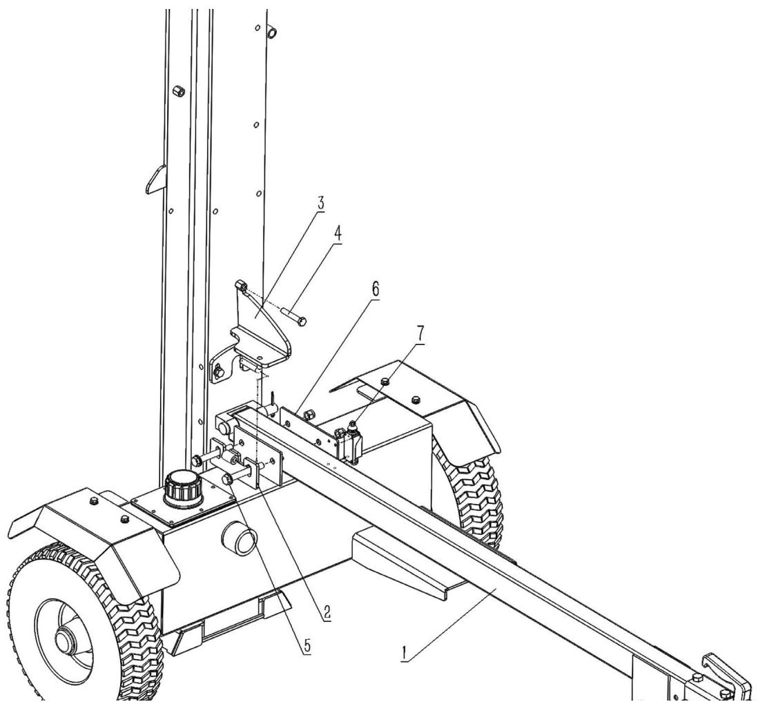
| 1 | Tow bar | 5 | M12x90 hardware | |
| 2 | Hook plate | 6 | Switch plate | |
| 3 | Vertical holder | 7 | Interlock switch | |
| 4 | M10x60 adjust bolt |
ATTENTION: Please assemble this interlock switch to avoid the log splitter working in horizontal position!
Engine assembling:
- Assemble the engine coupler (6) to the engine (1) shaft, make sure lining up the slot of them, and then insert the key way (11) to the slot, use the pump assembly (4) to adjust the position of the engine coupler to be well fitting with the pump coupler (4).
- Use the tailless screw to well fasten the engine coupler and put the rubber pad (3) to the engine coupler.
- Fasten pump assy. (4) to the engine with the four bolts(7), make sure the pump coupler and engine coupler are well gripped, then cover the pump assy. With the frame cover (9) and fasten with the two bolt (8).
- Assemble engine to the tank (5) with the shock pad and hardware (2).
- Connect the kill switch wire (refer to “Tank connection”) to the engine.

| 1 | Engine | 7 | M8x20 bolt | |
| 2 | Shock pad with hardware | 8 | M6x20 bolt | |
| 3 | Rubber pad | 9 | Frame cover | |
| 4 | Pump assembly | 10 | Tailless screw | |
| 5 | Hydraulic fluid tank | 11 | Keyway | |
| 6 | Engine coupler |
Hydraulic hoses connection:
- Connect the Suction hose (1) to the tank and pump and then fasten with hose clamp (6).
- Use pressure hose (4) to connect pump and control valve.
- Connect return hose (5) to the control valve and pump.
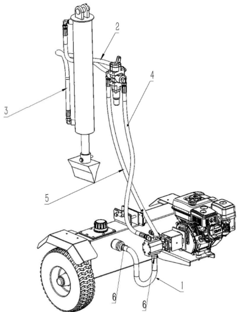
| 1 | Suction hose | 4 | Pressure hose | |
| 2 | Top hose | 5 | Return hose | |
| 3 | Bottom hose | 6 | Hose clamp |
Battery connection (for automatic-electric starters only):
Connect its positive lead to start relay (a) terminal, while connect its negative lead-wire to engine mounting screw, base screw or other grounding point with the engine (See the drawing below).
Check the battery's connecting point; make sure that it is tight and not oxidized – if so, than clean before connecting.
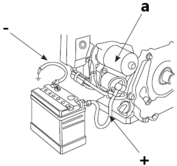
The breaker will cut off automatically to protect the charging circuit of the battery in the case that short circuit or incorrect connection of the battery poles occurs. The green indicator in the breaker will jump out with the circuit cutting off. After finding troubles and troubleshooting, depress the breaker button to turn the breaker on.
Pre-operation inspection
Oil check:
For shipping purposes the machine is drained of oil. Before first use add appropriate amount of fresh engine oil through the dipstick or oil plug. Use only recommended oil grade – do not overfill above the safe level!
- Remove the dipstick and clean it.
- Reinsert the dipstick into the oil filling hole without screwing it, and check oil level.
- If the oil level is too low (below the marked field on the dipstick), add the right amount of the engine oil and check its level again.
• Reinstall the dipstick.

a) Oil dipstick
b) Oil drain plug
c) Oil highest level
d) Oil lowest lever
CAUTION: run the engine with improper oil level – above or below the marked field may damage the engine!
Air filter:
Dismantle the air cleaner cover and check its element to make sure it clean, complete, and correctly installed.

- Remove the air cleaner outside cover (A). Be careful to prevent dirt and debris from falling into the air cleaner assembly.
- Separate the air filter (A) from the air filter housing (B).
- Inspect the air filter. Paper element: wash the element with home detergents and warm
• water (or non-flammable or high flash-point cleansing solvents) and - dry up. Foam element: Soak in clean engine oil until saturated. Squeeze out excess oil, otherwise, the engine will smoke in starting stage.
- Clean the air cleaner cover and inner surface with wet cloth, be careful not to allow the dust entering into the carburetor.
• Installation in reverse order to removal. - NOTE: do not use pressurized air or solvents to clean the filter. Pressurized air can damage the filter and solvents will dissolve the filter.
Refueling:
NOTE: the engine of the device is adapted only to burn unleaded gasoline without oil admixtures. The use of other fuel that is not fresh and with too high an ethanol content or of low quality can lead to engine failure. Refuel only with the engine off, paying close attention not to spill fuel over the engine, especially when it is hot - risk of fire! If the engine is warmed up, wait at least 2 minutes before refueling.

- Place the machine on a level, horizontal surface.
- The fuel tank is located on the top of the unit.
- Unscrew the fuel filler cap (with the dispenser icon). Do not pull out the strainer filter inside the opening!
- Refill fuel through the plug opening - the maximum fuel level in the tank should not exceed the upper limit of the red level gauge in the strainer filter, i.a. reach the bottom of the filler neck as max.
- NOTE: "light knocking" or "spark exploding" sound can be hear when the engine overloading. It is normal. Do not be worry about that. If "knocking" or "spark exploding" sound occur at a steady speed
under normal load, change the (brand) of gasoline; if such phenomena still happen, consult customer care for help, otherwise the engine may be damaged.
Device use
Startup
- Set the fuel valve - distributor icon - to the open position ("ON" - see the signature pictogram on the air filter housing) so that fuel can flow from the tank to the carburetor to start the engine.

- [Only when the engine is cold] Activate the choke, i.e. set the manual suction lever to the closed position ("CHOKE") - see the universal icon.
- Set the throttle lever - engine speed control - to approx. 1/2 scale in the direction of fast rotation. NOTE: the rabbit icon symbolizes fast rotation and the turtle is for slow speeds, so by moving the lever towards the appropriate icon, you increase or decrease the engine speed.
The Ground Truth image displays a single, solid horizontal line. According to Rule 2 (UNDERSCORE & LINE RULES), if the GT contains lines used for stylistic emphasis or as background elements (like ruled paper), the OCR result must ignore them. The line in the GT is clearly a stylistic or background line, not a placeholder for text. Therefore, the OCR should not have output any underscores. Outputting `____` constitutes an error under Rule 2, as it hallucinates placeholder symbols where none are semantically intended. No punctuation mismatch or formatting transformation applies here because the content is purely symbolic and not textual.

- After putting the ignition key to the “ON” position, grasp the lever of the recoil starter rope and pull in a steady motion until you feel resistance on the lever, then with a quick movement pull to the end, all the while holding the handle in your hand allowing it to return to the starting position in a controlled manner. Sometimes in freezing conditions, it may be necessary to pull the tug handle several times before the engine starts - this is normal.
ATTENTION: old or low-quality fuel can lead to starting problems! Change it immediately to a proper, fresh one.
- After starting the engine, let it work for a bit in order to reach the operating temperature after approx. 1 minute and during this time gradually move the manual suction lever in the direction of off ("RUN").
NOTE: starting a warmed-up engine does not require switching on the suction - its lever should be in the open position.
IMPORTANT: low speed is only for idling the engine - use the highest speed when operating the machine.
Stopping
- Set the slowest engine speed with the throttle lever (move it towards the turtle icon) and let the engine run at low speed for 1-2 minutes to cool it down a bit.
- Turn off the ignition by setting its switch to the "OFF" position. Also use this method for emergency stop of the machine.
- Alternatively, you can close the fuel valve (switch to the "OFF" position) and wait for the engine to stop - this method will get rid of residual fuel from the carburetor, so it is worth using it before storing an unused machine for a long time.
IMPORTANT: never use the choke lever to stop the engine by throttling it!
- If the machine will not be used any further, then close the fuel supply valve - set its lever to the closed ("OFF") position.
Low oil protection
Lack of engine oil may damage the engine. When oil level in the crankcase is too low, the engine oil alarm will stall the engine automatically to make it free of damage while the engine switch is still at "ON". If cannot restart the engine, check the engine oil level first before go to other check items.
Control lever:
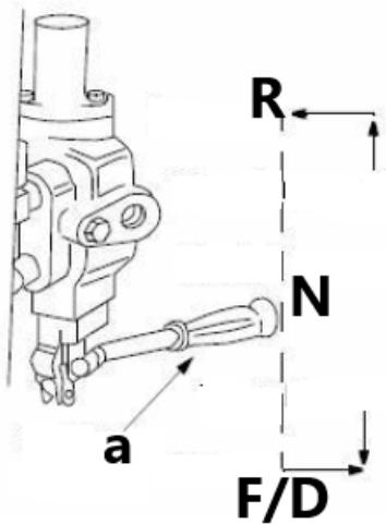
A – control lever
F/D – forward / downward wedge movement (depending on beam position)
N – neutral / stop
R - reverse (return the wedge)
- Move control lever forward or downward to move wedge down to split wood.
- Release the control handle to stop the wedge movement. It will return to neutral position as soon as handle is released.
- Move control lever reverse to return the wedge toward the cylinder. The control lever will lock in the disengaged position. It will return to neutral automatically when the full stroke is complete.
Horizontal & vertical beam position - locks
These two locks, as their name suggests, are used to secure the beam in the horizontal or the vertical position. The vertical beam lock is located next to the oil filter. The horizontal beam lock is located on the beam support latch bracket.
Splitting the log
- Place the machine on level, dry ground.
- Place the beam in either the vertical position and lock in place with the appropriate locking rod. To lock the beam in the vertical position pull out on the vertical beam lock to secure the beam. Make sure the stabilizer in right position and the support bolt stick to the beam as the below picture shows:

• Block the front and back of both wheels.
- Place the log against the end plate and only split wood in the direction of the grain.
CAUTION: never place hand on the end between the log and the splitting wedge!
- Stand in front of the unit to operate the control handle - move control lever down to split wood.
- Release the control lever to stop the wedge movement.
- Move control lever up to return the wedge.
Hydraulic system operating tips:
ALWAYS...
- Use clean fluid and check fluid level regularly.
• Use a filter (clean or replace regularly)
• Use a breather cap on fluid reservoir.
• Make sure pump is mounted and aligned properly. - Use a flexible “spider” type coupling between engine and pump drive shafts.
- Keep hoses clear and unblocked.
- Bleed air out of hoses before operating.
- Flush and clean hydraulic system before restarting after servicing.
- Use “pipe dope” on all hydraulic fittings.
- Allow time for warm-up before splitting wood.
- Prime the pump before initial start-up by turning over the engine with spark plug disconnected.
- Split wood along the grain (lengthwise) only.
NEVER...
- Use when the hydraulic fluid is below 6,6°C or above 65,5°C (see the thermometer on the tank).
• Use a solid engine /pump coupling.
- Operate through relief valve for long.
- Attempt to adjust unloading or relief valve settings without pressure gauges.
- Operate with air in hydraulic system.
• Use teflon tape on hydraulic fittings.
- Attempt to cut wood across the grain.
Raising and lowering the beam:
- Use control handle to run wedge up and down beam 6 to 8 times to circulate the hydraulic fluid, which will warm and thin the fluid.
- Place log splitter on a firm, level surface.
-
To raise the beam for vertical operation: Pull out the horizontal beam lock on the tongue.
-
Pivot beam lock down to release the beam.
- Move the beam to the vertical position. Secure it with the beam lock on the reservoir tank assembly.
- CAUTION: always use the log splitter in the vertical position when splitting heavy logs!
• To lower the beam: Pull out the vertical beam lock on the reservoir tank. - Pivot beam lock down to release the beam. Carefully pull back on beam and lower it to the horizontal position.
- Pull out the beam lock on the tongue, pivot it upwards and release it to hold the beam. Make certain it is latched securely.
Transporting the machine:
IMPORTANT: always turn the fuel valve to OFF position before transporting the log splitter.
- Lower the beam to its horizontal position. Make certain the beam is locked securely with the horizontal beam lock.
- Raise the adjustable jack stand by turning the crank handle clockwise.
- If the coupler hitch does not fit on the ball, turn the adjustment nut one turn counterclockwise.
- If the coupler hitch is too loose on the ball, turn the adjustment nut one turn clockwise.
- Connect the safety chains to the towing vehicle.
• Do not tow it on public roads and at speeds exceeding 70 km/h!
Wedge assembly adjustment:
As normal wear occurs and there is excessive “play” between the wedge and beam, adjust the bolts on the side of the wedge assembly to eliminate excess space between the wedge and the beam.
- Loosen the jam nuts on the two adjustment bolts on the side of the wedge.
- Turn the adjustment bolts in until snug and then back them off slowly until the wedge assembly will slide on the beam.
- Tighten the jam nuts securely against the side of the wedge to hold the adjustment bolts in this position.
Maintenance
WARNING: before cleaning, lubricating, repairing, or inspecting, disengage the control lever and stop engine. Disconnect the spark plug wire and ground it against the engine to prevent unintended starting.
a) Engine service intervals:
| Item↓Frequency→ | Before each use | First 1 month or first 20 hrs of operation | Thereafter, every 3 months or every 50 hrs of operation | Every year or every 100 hrs of operation | |
| Engine oil | Check - Refill | √ | |||
| Replacement | √ | √ | |||
| Reduction gear oil (if equipped) | Fluid level check | √ | |||
| Replacement | √ | √ | |||
| Air filter | Check | √ | |||
| Cleaning | √ | ||||
| Replacement | √ | ||||
| Deposit cup (if equipped) | Cleaning | √ | |||
| Spark plug | Check - adjust | √* | |||
| Spark arrester (if equipped) | Cleaning | √ | |||
| Idling ( if equipped)** | Check - adjustment | √ | |||
| Valve clearance** | Check - adjustment | √ | |||
| Fuel tank & fuel filter ** | Cleaning | √ | |||
| Fuel lines | Check | Every 2 years (replacement if necessary) | |||
| Cylinder head, piston | Clean up carbon deposit ** | Every 125 hrs of operation | |||
| * These items should be replaced if replacement needed. | |||||
| ** These items should be maintained and repaired by our authorized dealer, unless the owner has appropriate tools and is proficient with mechanical maintenance. | |||||
NOTE:
- If the gasoline engine frequently work under high temperature or heavy load, change the oil every 25 hours.
- If the engine frequently work under dusty or other severe circumstances, clean the air filter element every 10 hours; If necessary, change the air filter element every 25 hours.
- The maintenance period and the exact time (hour), the one which comes first.
b) Hydraulic fluid and filter
- Check the hydraulic fluid level in the log splitter reservoir tank before each use.
- Maintain fluid level within the range specified on the dipstick at all times.
- Change the hydraulic fluid in the reservoir every 100 hours of operation.
- Disconnect the suction hose from the bottom of the reservoir tank and drain the fluid into a suitable container.
- Change the hydraulic filter every 50 hours of operation. Use only a 10 micron hydraulic filter.
c) Beam and splitting wedge
- Lubricate both sides of the beam (where it comes into contact with the splitting wedge) before each use, with engine oil. The wedge plate on the log splitter is designed so the gibs on the side of the wedge plate can be removed and rotated and/or turned over for even wear.
- Make certain to readjust the adjustment bolts so wedge moves freely, but no excess space exists between the wedge plate and the beam.
d) Hose clamps
- Check, before each use, if hose clamps on the suction hose (attached to the side of the pump) are tight. Check the hose clamps on the return hose at least once a season.
e) Wheels and tires
- Maintain equal pressure on all tires - see sidewall of tire for recommended pressure.
f) Before each cleaning, adjustment or replacement of accessories, and when the unit is not in use, turn off the machine and cool it down completely, also remove the ignition cable pipe from the spark plug.
g) Wait until the rotating parts stop.
h) Use only non-corrosive cleaning agents for cleaning the surfaces.
i) Store the unit in a dry and cool place protected from moisture and direct sunlight.
j) Do not spray the unit with a stream of water or immerse it in water.
k) Make sure that no water enters through the ventilation openings in the casing.
I) Clean the ventilation openings with a brush and compressed air.
m) Perform regular inspections of the unit checking technical fitness and any damages.
n) Do not use sharp and/or metal objects (e.g. wire brush or metal spatula) for cleaning as they may damage the surface of the appliance material.
o) Check the fuel cables regularly for any damage or wear (cracks or leaks) and replace the damaged component immediately.
p) Spark plug inspection/replacement:
ATTENTION: remove the plug only on a cold engine!
Access to the plug is between the air filter housing and the muffler. First, remove the ignition cable pipe from the spark plug to gain access to it. Before installing a spark plug - including a new spark plug - check the spark plug gap and adjust it if necessary. When screwing in the plug, do so as far as it will
go, but tighten it sensitively - usually another 1/3-1/2 turns (see the plug manufacturer's recommendations). The rest of the assembly reverses to disassembly.

q) Changing the engine oil:

- Place the machine on a flat surface, switch on the machine and warm up the engine for a few minutes, then switch it off.
- Remove the oil filler cap with the dipstick.
- Put the oil slick container under the engine at the drain plug.
- Unscrew the oil drain plug and drain all the oil - until it stops leaking.
- Turn the drain plug back on and refill it with fresh oil through the filler plug with a dipstick according to the procedure described earlier in this manual.
r) Prolonged non-use of the machine (>1 month):
- Empty the fuel from the tank or add a fuel stabilizer to it according to the manufacturer's proportion of the additive.
NOTE: do not keep fuel in a tank with a stabilizer for longer than the manufacturer of the additive recommends!
- [Only if the fuel is emptied from the tank] Start the engine and let it run without load until it shuts down on its own due to lack of fuel - this will allow the residual fuel to empty from the fuel system and carburetor. Any residue can be drained by unscrewing the precipitation filter:
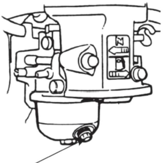
• Turn off the precipitation filter and close the fuel valve.
- Replace the engine oil with fresh oil (if it has not been changed recently or shows signs of wear).
- On a cold engine, remove the ignition wire pipe from the spark plug and unscrew the spark plug and pour 5-10 ml of fresh engine oil into the cylinder through its opening. Screw the spark plug back in.
- Pull the starter tug handle until you feel resistance so that the oil is distributed in the cylinder preserving the engine from the inside. Next, make 8-10 slow movements with the pull as if you wanted to start the engine.
- Clean the device, especially the engine, from dirt and other contaminants such as dust.
- Inspect the machine for worn or damaged parts - replace them if necessary.
- If necessary, inflate the air in the wheels to the maximum allowable pressure (see the marking on the tire).
- Store the machine in a dry, roofed building with good ventilation and away from heat and sunlight.
Troubleshooting
| ENGINE | ||
| Problem | Possible cause | Solution |
| Engine fails to start | 1. Spark plug wire disconnected.2. Fuel tank empty or stale fuel.3. Fuel shut-off valve closed.4. Throttle lever not in correct starting position.5 Choke not turned on.6. Engine not primed properly.7. Blocked fuel line8. Faulty spark plug | 1. Connect wire to spark plug2. Fill tank with clean, fresh fuel.3. Turn the valve to ON position4. Move throttle lever to fast position.5. Move choke to on position.6. Prime engine.7. Clean fuel line.8. Clean, adjust gap, or replace. |
| Engine runs erratic | 1. Spark plug wire loose or broken.2. Unit running on choke.3. Blocked fuel line or stale fuel.4. Water or dirt in fuel system.5. Dirt air filter.6. Carburetor out of adjustment. | 1. Connect and tighten spark plug wire or replace it.2. Move choke lever to off position.3. Clean fuel line, fill tank with clean, fresh fuel.4. Drain fuel tank and refill with fresh fuel.5. Clean or replace the air filter.6. See the manufacturer's service. |
| Engine overheats | 1. Engine oil level low.2. Dirty air filter.3. Carburetor not adjusted properly. | 1. Fill crankcase with proper amount of oil.2. Clean or replace the air filter.3. See the manufacturer's service. |
| HYDRAULIC SYSTEM | ||
| Problem | Possible cause | Solution |
| Cylinder rod will not move | 1. Broken drive shaft.2. Shipping plugs left in hoses.3. Coupling not adjusted properly.4. Loose shaft coupling.5. Damaged gear sections.6. Damaged relief valve.7. Blocked hydraulic lines.8. Incorrect oil level.9. Damaged or blocked directional valve. | 1. Contact service dealer.2. Disconnect and remove plugs.3. Adjust per manual.4. Correct coupling.5-10. Service system and dealer assistance. |
| Slow cylinder shaft speed | 1. Damaged gear sections.2. Excessive pump inlet vacuum.3. Slow engine speed.4. Damaged relief valve.5. Incorrect/contaminated oil.6. Internal valve or cylinder damage. | 1-3. Inspect and repair with dealer support.4. Check oil quality and refill/replace.5-6. Drain, clean system. |
| Leaking cylinder | 1. Broken seals.2. Scored cylinder. | 1-2. Contact service dealer for seal and cylinder repair. |
| Engine runs but wood won't split | 1. Damaged gear section.2. Pump check valve leaking.3. Excessive pump inlet vacuum.4. Incorrect/contaminated oil.5. Overloaded or damaged cylinder. | 1-8. Service dealer for all system checks, including oil and cylinder performance. |
| Engine stalls during splitting | 1. Weak engine/low horsepower.2. Overloaded cylinder. | 1-2. Dealer assistance; avoid improper splitting techniques. |
| Engine will not turn or stalls | 1. Misalignment.2. Frozen or seized pump.3. Weak engine.4. Hydraulic line blockage.5. Blocked valve. | 1. Adjust alignment.2. Service for pump issues.3-5. Flush system or repair faults with dealer guidance. |
| Leaking pump shaft seal | 1. Drive shaft issue.2. Misalignment.3. Damaged seals or gaskets.4. Plugged oil breather. | 1-5. Dealer support for breather and seal repair; ensure proper alignment. |
Disposing of used devices
Do not dispose of this device in municipal waste systems. Hand it over to an electric and electrical device recycling and collection point. Check the symbol on the product, instruction manual and packaging. The plastics used to construct the device can be recycled in accordance with their markings. By choosing to recycle you are making a significant contribution to the protection of our environment.
Contact local authorities for information on your local recycling facility.

A – ovládací páka
R – reverse (retourner le coin)
A – leva di comando
| 1 | Barra de remolque | 5 | Tornillería M12x90 | |
| 2 | Placa de gancho | 6 | Placa de interruptor | |
| 3 | Soporte vertical | 7 | Interruptor de enclavamiento | |
| 4 | Perno de ajuste M10x60 |
A – palanca de control
A - vezérlőkar
| 1 | Sugeslange | 4 | Trykslange | |
| 2 | ∅verste slange | 5 | Returslange | |
| 3 | Slange i bunden | 6 | Slangeklemme |
Batteriforbindelse (kun til automatiske elektriske startere):
| 1 | Imuletku | 4 | Paineletku | |
| 2 | Yläletku | 5 | Paluuletku | |
| 3 | Pohja letku | 6 | Letkunkiristin |
A – ohjausvipu
| 1 | Straal | 10 | Trekhaakklem | |
| 2 | Bescherm pijp | 11 | M10x35 zeskantbout | |
| 3 | Loghouder | 12 | M10 vlakke ring | |
| 4 | Fjeder | 13 | M10 vlakke ring | |
| 5 | M8x45 zeskantbout | 14 | M10 veerring | |
| 6 | M8 platte ring | 15 | M10 borgmoer | |
| 7 | M8 veerring | 16 | Handvat | |
| 8 | M8 borgmoer | 17 | Montageplaat | |
| 9 | Bedieningshendel | M10x35-hardware |
Montage trekhaak:
| 1 | Motor | 7 | M8x20 bout | |
| 2 | Schokdemper met hardware | 8 | M6x20 bout | |
| 3 | Rubberen pad | 9 | Kaderafdekking | |
| 4 | Pomp montage | 10 | Staartloze schroef | |
| 5 | Hydraulische vloeistoftank | 11 | Sleutelgat | |
| 6 | Motorkoppeling |
| 1 | Zuigslang | 4 | Drukslang | |
| 2 | Bovenste slang | 5 | Retourslang | |
| 3 | Onderste slang | 6 | Slangklem |
A – bedieningshendel
| 1 | Slepeball | 42 | Pumpens inntaksslange | |
| 2 | Kjetting | 43 | Inntaksslangekobling | |
| 3 | Tilhengerfeste | 44 | Rampinne | |
| 4 | Pumpens utløpsslange | 45 | Vaskemaskin | |
| 5 | Splint | 46 | Høyre stang | |
| 6 | Tilhengerfestepinne | 47 | 1/2 kontakt | |
| 7 | Returslange | 48 | Vær | |
| 8 | Gjørmevakt (til venstre) | 49 | Rett kobling | |
| 9 | Tanklokk | 50 | Gjenopprett røret | |
| 10 | O-tetning | 51 | Høyre kontakt | |
| 11 | Hydraulisk filter | 52 | Blad | |
| 12 | Tanksirkeltetning | 53 | Bladfiksering | |
| 13 | Tankdeksel | 54 | Bjelke | |
| 14 | Tank rett tetning | 55 | Fjær | |
| 15 | Slamskjerm (høyre) | 56 | Stang | |
| 16 | Høyre roter stangen | 57 | Vaskemaskin | |
| 17 | M8x50 bolt | 58 | Hjul | |
| 18 | Strålestøtte | 59 | Støpsel | |
| 19 | Tilhengerfestefeste | 60 | Tank | |
| 20 | Klinke | 61 | Avstandsstykke | |
| 21 | Bjelkestøttefiksering | 62 | Slip plate | |
| 22 | Ventilstift | 63 | Vaskemaskin | |
| 23 | Bjelkehåndtak | 64 | Avstandsstykke | |
| 24 | Ventil | 65 | Venstre beskytter | |
| 25 | M24 spormutter | 66 | Justerbar plate | |
| 26 | Hjuldeksel | 67 | M6x50 ring | |
| 27 | ∅8x50 pinne | 68 | Fjær | |
| 28 | ∅8x33 pinne | 69 | Støttefot | |
| 29 | Aktiv stang topp festeplate | 70 | Venstre bord | |
| 30 | Fjærskive | 71 | Bryter | |
| 31 | Fjær | 72 | Bytt plate | |
| 32 | Aksel | 73 | Rambunnslange | |
| 33 | Ventilstang | 74 | Ram toppslange | |
| 34 | Motor | 75 | Sikkerhetsrør | |
| 35 | Gjenopprett stang | 76 | Rambøyle | |
| 36 | Koblingsramme | 77 | M8x40 bolt | |
| 37 | Koblingsdeksel | 78 | M12x55 bolt | |
| 38 | Motorkobling | 79 | Blad | |
| 39 | Plomme plastspjeld | 80 | M12x80 bolt | |
| 40 | Pumpekobling | 81 | Bladfesteplate | |
| 41 | Pumpe | 82 | Avstandsplate |

a) Luftfilterhus
b) Drivstofftanklokk
c) Drivstofftank
d) Lyddemper med skjerm
e) Tennplugg med ledningsboks
f) Gasspak
g) Choke spak
h) Drivstoffkran
i) Forgasser
j) Rekylstarter
k) Rekylstarterhåndtak
I) Tenningsbryter
m) Oljebeskytter
n) Motoroljepeilepinne
o) Dreneringsplugg for motorolje
p) Olje (påfyllings) plugg
Installasjon
| 1 | Motor | 8 | Pumpe | |
| 2 | Stokkeholder | 9 | Vertikal holder | |
| 2 | Hjul | 10 | Beskytt røret | |
| 4 | Tank | 11 | Bjelke | |
| 5 | Gjørmevakt | 12 | Slanger | |
| 6 | Tilhengerfeste | 13 | Forfot | |
| 7 | Tilhengerfesteklemme | 14 | Bytt plate |
Før montering:
| 1 | Bjelke | 10 | Tilhengerfesteklemme | |
| 2 | Beskytt røret | 11 | M10x35 sekskantbolt | |
| 3 | Stokkeholder | 12 | M10 flat skive | |
| 4 | Fjær | 13 | M10 flat skive | |
| 5 | M8x45 sekskantbolt | 14 | M10 fjærskive | |
| 6 | M8 flat skive | 15 | M10 låsemutter | |
| 7 | M8 fjærskive | 16 | Håndtak | |
| 8 | M8 låsemutter | 17 | Monteringsplate | |
| 9 | Kontrollhåndtak | M10x35 maskinvare |
| 1 | Bjelke | 5 | Bjelkepinne | |
| 2 | Tilhengerfeste | 6 | Splint | |
| 3 | Forfot | 7 | M10x70 pinnesett | |
| 4 | Senterbase | 8 | M10x80 bolt |
| 1 | Tank | 7 | M8x20 bolt | |
| 2 | Hjul | 8 | M8 flat skive | |
| 3 | Splint | 9 | M8 fjærskive | |
| 4 | Spaltet enhet | 10 | M8 låsemutter | |
| 5 | Lokk | 11 | Stor vaskemaskin | |
| 6 | Gjørmevakt |
Tanktilkobling:
- Sett de to boltene (5) gjennom krokplaten (5), tanken, tilhengerfestet (1), bryterplaten (6) og fest den deretter med låsemutteren.
- Hekt den vertikale holderen (3) til krokplaten (2) hvis den ikke er forhåndsmontert.

| 1 | Tilhengerfeste | 5 | M12x90 maskinvare | |
| 2 | Krokplate | 6 | Bytt plate | |
| 3 | Vertikal holder | 7 | Forriglingsbryter | |
| 4 | M10x60 justeringsbolt |
| 1 | Motor | 7 | M8x20 bolt | |
| 2 | Støtpute med maskinvare | 8 | M6x20 bolt | |
| 3 | Gummipute | 9 | Rammedeksel | |
| 4 | Pumpemontering | 10 | Skrue uten hale | |
| 5 | Hydraulikkvæsketank | 11 | Keyway | |
| 6 | Motorkobling |
Hydraulikkslanger tilkobling:
| 1 | Sugeslange | 4 | Trykkslange | |
| 2 | Toppslange | 5 | Returslange | |
| 3 | Bunnslange | 6 | Slangeklemme |
Batteritilkobling (kun for automatisk-elektriske startere):
Koble dens positive ledning til startrelé (a)-terminalen, mens dens negative ledning kobles til motorens monteringsskrue, basisskrue eller annet jordingspunkt med motoren (se tegningen nedenfor). Sjekk batteriets tilkoblingspunkt; sørg for at den er tett og ikke oksidert – i så fall rengjør den før du kobler til.

- [Kun när motoren er kald] Aktiver choken, dvs. sett den manuelle sugespaken i lukket stilling ("CHOKE") - se universalikonet.
- Still inn gasspaken - motorhastighetskontroll - på ca. 1/2 skala i hurtigrotasjonsretningen. MERK: kaninikonet symboliserer rask rotasjon og skilpadden er for lave hastigheter, så ved å flytte spaken mot det aktuelle ikonet øker eller reduserer du motorhastigheten.
The Ground Truth image displays a single, solid horizontal line. According to Rule 2 (UNDERSCORE & LINE RULES), this is a stylistic or background line, not a placeholder underscore. Therefore, the OCR result must ignore it and output nothing or only meaningful text. The provided OCR content is "____", which consists of four underscores. This is an incorrect interpretation of the line as a placeholder, violating the rule that stylistic lines must be ignored. The OCR has hallucinated placeholder underscores where none should exist in the GT. Hence, the OCR result is inconsistent with the Ground Truth.

A – kontrollspak
| 1 | Balk | 5 | Strålstift | |
| 2 | Dragkrok | 6 | Saxnål | |
| 3 | Framfot | 7 | M10x70 stiftset | |
| 4 | Mittbas | 8 | M10x80 bult |
| 1 | Sugslang | 4 | Tryckslang | |
| 2 | Toppslang | 5 | Returslang | |
| 3 | Nedre slang | 6 | Slangklämma |
A – manöverspak
| 1 | Motor | 8 | Bombear | |
| 2 | Porta-troncos | 9 | Suporte vertical | |
| 2 | Roda | 10 | Proteger tubo | |
| 4 | Tanque | 11 | Feixe | |
| 5 | Guarda-lamas | 12 | Mangueiras | |
| 6 | Barra de reboque | 13 | Antepé | |
| 7 | Grampo de barra de reboque | 14 | Placa de interruptor |
Antes da montagem:
| 1 | Barra de reboque | 5 | Ferragens M12x90 | |
| 2 | Placa de gancho | 6 | Placa de interruptor | |
| 3 | Suporte vertical | 7 | Interruptor de intertravamento | |
| 4 | Parafuso de ajuste M10x60 |
| 1 | Motor | 7 | Parafuso M8x20 | |
| 2 | Almofada de choque com ferragens | 8 | Parafuso M6x20 | |
| 3 | Almofada de borracha | 9 | Capa de quadro | |
| 4 | Montagem da bomba | 10 | Parafuso sem cauda | |
| 5 | Tanque de fluido hidráulico | 11 | Rasgo de chaveta | |
| 6 | Acoplador do motor |
Conexão de mangueiras hidráulicas:
A – alavanca de controle
| 1 | Čažná guľa | 42 | Prívodná hadica čerpadla | |
| 2 | reťaz | 43 | Konektor prívodnej hadice | |
| 3 | Čažná tyč | 44 | Špendlík barana | |
| 4 | Výstupná hadica čerpadla | 45 | Podložka | |
| 5 | Závlačka | 46 | Pravá tyč | |
| 6 | Čap ťažného zariadenia | 47 | 1/2 konektora | |
| 7 | Spätná hadica | 48 | Ram | |
| 8 | Blatník (vl’avo) | 49 | Priamy konektor | |
| 9 | Uzáver nádrže | 50 | Obnovit potrubie | |
| 10 | O-tesnenie | 51 | Pravý konektor | |
| 11 | Hydraulický filter | 52 | Čepel' | |
| 12 | Kruhové tesnenie nádrže | 53 | Fixácia čepele | |
| 13 | Kryt nádrže | 54 | Beam | |
| 14 | Priame tesnenie nádrže | 55 | jar | |
| 15 | Blatník (vpravo) | 56 | Rod | |
| 16 | Otočte tyč doprava | 57 | Podložka | |
| 17 | Skrutka M8x50 | 58 | koleso | |
| 18 | Podpora lúča | 59 | Zástrčka | |
| 19 | Upevnenie ťažného zariadenia | 60 | Nádrž | |
| 20 | Západka | 61 | Rozperka | |
| 21 | Upevnenie podpory nosníka | 62 | Sklzový tanier | |
| 22 | Ventilový čap | 63 | Podložka | |
| 23 | Rukovát’ lúča | 64 | Rozperka | |
| 24 | Ventil | 65 | L’avý chránič | |
| 25 | M24 drážková matica | 66 | Nastavitelná doska | |
| 26 | Kryt kolesa | 67 | Prsteň M6x50 | |
| 27 | ∅8x50 kolík | 68 | jar | |
| 28 | ∅8x33 kolík | 69 | Podporná noha | |
| 29 | Aktívna horná upevňovacia doska tyče | 70 | L’avá doska | |
| 30 | Pružinová podložka | 71 | Prepínač | |
| 31 | jar | 72 | Spínacia doska | |
| 32 | Valček | 73 | Spodná hadica barana | |
| 33 | Ventilová tyč | 74 | Horná hadica barana | |
| 34 | Motor | 75 | Bezpečnostné potrubie | |
| 35 | Obnovit' tyč | 76 | Ramená obruč | |
| 36 | Rám konektora | 77 | Skrutka M8x40 | |
| 37 | Kryt spojky | 78 | Skrutka M12x55 | |
| 38 | Spojka motora | 79 | Čepel' | |
| 39 | Slivkový plastový tlmič | 80 | Skrutka M12x80 | |
| 40 | Spojka čerpadla | 81 | Doska na pripevnenie čepele | |
| 41 | Pumpa | 82 | Dištančná doska |

| 1 | Nádrž | 7 | Skrutka M8x20 | |
| 2 | koleso | 8 | Plochá podložka M8 | |
| 3 | Závlačka | 9 | Pružinová podložka M8 | |
| 4 | Štrbinová jednotka | 10 | Poistná matica M8 | |
| 5 | Čiapka | 11 | Veľká práčka | |
| 6 | Blato strážca |
Pripojenie nádrže:
| 1 | Sacia hadica | 4 | Tlaková hadica | |
| 2 | Horná hadica | 5 | Spätná hadica | |
| 3 | Spodná hadica | 6 | Hadicová svorka |
A – ovládacia páka
Α – μοχλός ελέγχου
| 1 | Kugla za vuču | 42 | Ulazno crijevo pumpe | |
| 2 | Lanac | 43 | Priključak dovodnog crijeva | |
| 3 | Kuka za vuču | 44 | Ram klin | |
| 4 | Izlazno crijevo pumpe | 45 | Perilica | |
| 5 | Rascjepka | 46 | Desna šipka | |
| 6 | Zatik kuke za vuču | 47 | 1/2 priključak | |
| 7 | Povratno crijevo | 48 | Ovan | |
| 8 | Zaštita od blata (lijevo) | 49 | Ravni konektor | |
| 9 | Čep spremnika | 50 | Vratite cijev | |
| 10 | O-brtvljenje | 51 | Desni konektor | |
| 11 | Hidraulički filter | 52 | Sječivo | |
| 12 | Kružna brtva spremnika | 53 | Učvršćivanje oštrice | |
| 13 | Poklopac spremnika | 54 | Greda | |
| 14 | Ravna brtva spremnika | 55 | Proljeće | |
| 15 | Zaštita od blata (desno) | 56 | Štap | |
| 16 | Desno rotirajte šipku | 57 | Perilica | |
| 17 | M8x50 vijak | 58 | Kotač | |
| 18 | Nosač grede | 59 | Utikač | |
| 19 | Pričvršćivanje kuke za vuču | 60 | Tenk | |
| 20 | zasun | 61 | Razmaknica | |
| 21 | Fiksacija nosača grede | 62 | Klizna ploča | |
| 22 | Zatik ventila | 63 | Perilica | |
| 23 | Ručka grede | 64 | Razmaknica | |
| 24 | Ventil | 65 | Lijevi zaštitnik | |
| 25 | M24 utorna matica | 66 | Podesiva ploča | |
| 26 | Poklopac kotača | 67 | M6x50 prsten | |
| 27 | Zatik 8x50 | 68 | Proljeće | |
| 28 | Zatik 8x33 | 69 | Potporno stopalo | |
| 29 | Ploča za pričvršćivanje na vrhu aktivne šipke | 70 | Lijeva ploča | |
| 30 | Opruga za pranje | 71 | Prekidač | |
| 31 | Proljeće | 72 | Preklopna ploča | |
| 32 | Valjak | 73 | Ram donje crijevo | |
| 33 | Šipka ventila | 74 | Navucite gornje crijevo | |
| 34 | Motor | 75 | Sigurnosna cijev | |
| 35 | Vratite šipku | 76 | Ram obruč | |
| 36 | Konektorski okvir | 77 | M8x40 vijak | |
| 37 | Poklopac spojnice | 78 | M12x55 vijak | |
| 38 | Spojka motora | 79 | Sječivo | |
| 39 | Plum plastični amortizer | 80 | M12x80 vijak | |
| 40 | Spojnica pumpe | 81 | Ploča za postavljanje oštrice | |
| 41 | Pumpa | 82 | Razmakna ploča |

a) Kućište filtera za zrak
b) Čep spremnika goriva
c) Spremnik goriva
d) Prigušivač sa štitnikom
e) Svjećica sa žičanom kabinom
f) Poluga gasa
g) Poluga prigušnice
h) Ventil za gorivo
i) rasplinjač
j) Povratni starter
k) Ručka povratnog startera
I) Prekidač paljenja
m) Štitnik za ulje
n) Šipka za mjerenje ulja u motoru
o) Čep za ispuštanje motornog ulja
p) Čep za ulje (punjenje).
Montaža
Raspakiranje iz sanduka:
| 1 | Motor | 8 | Pumpa | |
| 2 | Držač trupaca | 9 | Vertikalni držač | |
| 2 | Kotač | 10 | Zaštitite cijev | |
| 4 | Tenk | 11 | Greda | |
| 5 | Zaštita od blata | 12 | Crijeva | |
| 6 | Kuka za vuču | 13 | Prednja noga | |
| 7 | Stezaljka kuke za vuču | 14 | Preklopna ploča |
Prije sastavljanja:
| 1 | Greda | 5 | Zatik za gredu | |
| 2 | Kuka za vuču | 6 | Rascjepka | |
| 3 | Prednja noga | 7 | Set klinova M10x70 | |
| 4 | Središnja baza | 8 | M10x80 vijak |
Sastavljanje spremnika hidraulične tekućine:
- Sastavite oba štitnika za blato (6) na spremnik (1) i pričvrstite ih M8 okovom (7-10).
- Pričvrstite na osovinu spremnika redom s velikom podloškom (11), kotačem (2), podloškom osovine (11), a zatim pričvrstite maticom s prorezom (4), umetnite zatik (3) u rupu osovine i razdvojite zatik za spriječite da ispadne, pričvrstite poklopac (5) na kotač.
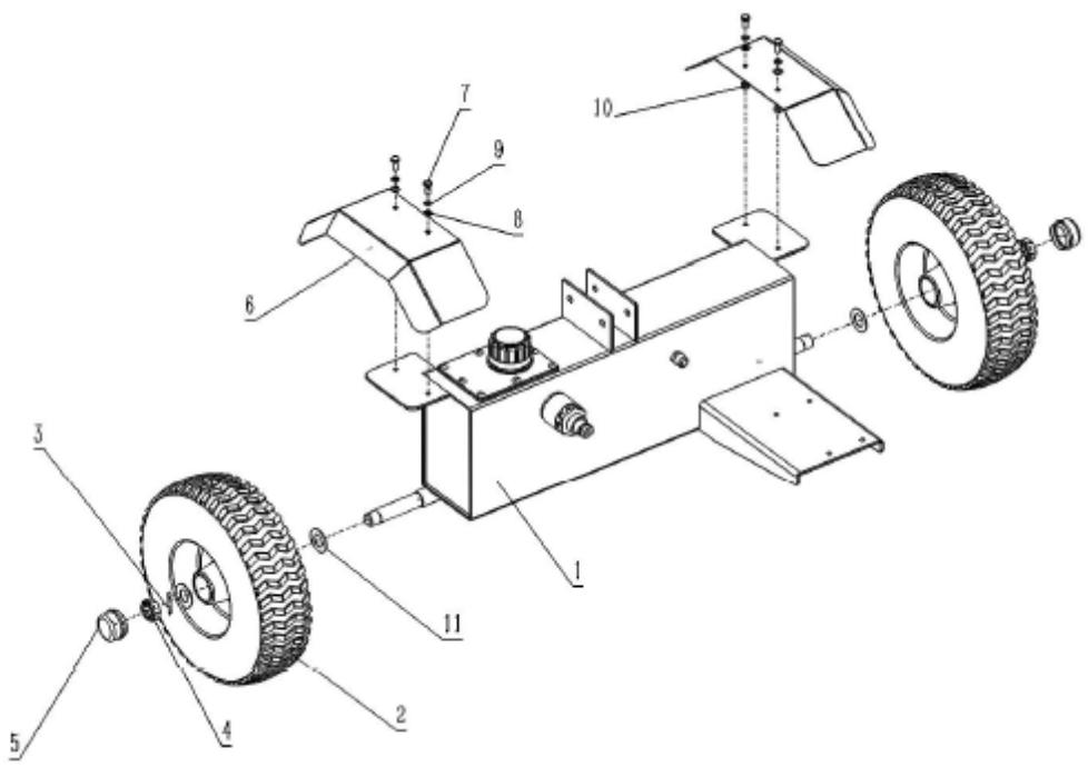
| 1 | Tenk | 7 | M8x20 vijak | |
| 2 | Kotač | 8 | M8 ravna podloška | |
| 3 | Rascjepka | 9 | M8 opružna pločica | |
| 4 | Jedinica s prorezima | 10 | Sigurnosna matica M8 | |
| 5 | kapa | 11 | Velika perilica | |
| 6 | Zaštita od blata |
Priključak spremnika:
- Umetnite dva vijka (5) kroz ploču kuke (5), spremnik, polugu za vuču (1), ploču prekidača (6) i zatim pričvrstite sigurnosnom maticom.
- Zakačite okomiti držač (3) za ploču s kukom (2) ako nije prethodno montiran.

| 1 | Kuka za vuču | 5 | M12x90 hardver | |
| 2 | Kukasta ploča | 6 | Preklopna ploča | |
| 3 | Vertikalni držač | 7 | Prekidač za blokiranje | |
| 4 | M10x60 vijak za podešavanje |
| 1 | Motor | 7 | M8x20 vijak | |
| 2 | Amortizer s hardverom | 8 | M6x20 vijak | |
| 3 | Gumeni jastučić | 9 | Poklopac okvira | |
| 4 | Sklop pumpe | 10 | Vijak bez repa | |
| 5 | Spremnik hidraulične tekućine | 11 | Utor za ključ | |
| 6 | Spojka motora |
Spajanje hidrauličnih crijeva:
- Spojite usisno crijevo (1) na spremnik i pumpu i zatim ga pričvrstite stezaljkom za crijevo (6).
- Koristite tlačno crijevo (4) za spajanje pumpe i upravljačkog ventila.
- Spojite povratno crijevo (5) na regulacijski ventil i pumpu.

- Skinite vanjski poklopac pročistača zraka (A). Pazite da spriječite da prljavština i krhotine upadnu u sklop pročistača zraka.
- Odvojite filtar zraka (A) od kućišta filtra zraka (B).
- Pregledajte filtar zraka. Papirnati element: element operite kućnim deterdžentima i na toplo
• vodu (ili nezapaljiva ili otapala za čišćenje s visokom točkom paljenja) i - isušiti. Pjenasti element: Namočite u čisto motorno ulje dok se ne zasiti. Istisnite višak ulja, inače će motor dimiti u fazi pokretanja.
- Očistite poklopac pročistača zraka i unutarnju površinu mokrom krpom, pazite da prašina ne uđe u karburator.
- Ugradnja obrnutim redoslijedom od uklanjanja.
- NAPOMENA: nemojte koristiti zrak pod pritiskom ili otapala za čišćenje filtera. Zrak pod tlakom može oštetiti filtar, a otapala će ga otopiti.
Punjenje goriva:
- [Samo kad je motor hladan] Aktivirajte prigušnicu, tj. postavite ručicu ručnog usisavanja u zatvoreni položaj ("ČOK") - pogledajte univerzalnu ikonu.
- Namjestite ručicu gasa - kontrolu broja okretaja motora - na pribl. 1/2 mjerila u smjeru brze vrtnje. NAPOMENA: ikona zeca simbolizira brzu rotaciju, a kornjača je za male brzine, tako da pomicanjem ručice prema odgovarajućoj ikoni povećavate ili smanjujete brzinu motora.

a) Oro filtro korpusas
b) Kuro bako dangtelis
c) Kuro bakas
d) Duslintuvas su apsauga
e) Uždegimo žvakė su vielos kabina
f) Droselio svirtis
g) Droselio svirtis
h) Kuro čiaupas
i) Karbiuratorius
j) Atatrankos starteris
k) Atatürkos starterio rankena
I) Uždegimo jungiklis
m) Alyvos apsauga
n) Variklio alyvos matuoklis
o) Variklio alyvos išleidimo kaištis
p) Alyvos (pildymo) kamštis
Montavimas
A – valdymo svirtis
a) Carcasa filtrului de aer
b) Capac rezervor combustibil
c) Rezervor de combustibil
d) Toba de eşapament cu protectie
e) Bujie cu cabină de sârmă
f) Maneta de acceleratie
g) Maneta de sufocare
h) Robinet de combustibil
i) Carburator
j) Starter cu recul
k) Mâner demaror cu recul
I) Comutator de aprindere
m) Protector de ulei
n) Joja de ulei de motor
o) Buşon de golire a uleiului de motor
p) Buşon (de umplere) cu ulei
Instalare
| 1 | Furtun de aspiratie | 4 | Furtun de presiune | |
| 2 | Furtun de sus | 5 | Furtun de retur | |
| 3 | Furtun de jos | 6 | Colieră pentru furtun |
A – maneta de control
a) Ohišje zračnega filtra
b) Pokrov rezervoarja za gorivo
c) Rezervoar za gorivo
d) Dušilec z varovalom
e) Vžigalna svečka s kabino za žice
f) Ročica za plin
g) Ročica dušilke
h) Pipa za gorivo
i) Uplinjač
j) Povratni zaganjalnik
k) Ročaj povratnega zaganjalnika
I) Stikalo za vžig
m) Ščitnik za olje
n) Merilna palica za motorno olje
o) Čep za izpust motornega olja
p) Čep za olje (polnjenje).
Namestitev
| 1 | Žarek | 5 | Zatič žarka | |
| 2 | Vlečna kljuka | 6 | Razcepka | |
| 3 | Sprednji del stopala | 7 | Komplet zatičev M10x70 | |
| 4 | Sredinska osnova | 8 | M10x80 vijak |
| 1 | Rezervoar | 7 | M8x20 vijak | |
| 2 | kolo | 8 | Ploščata podložka M8 | |
| 3 | Razcepka | 9 | M8 vzmetna podložka | |
| 4 | Enota z režami | 10 | Protimatica M8 | |
| 5 | kapa | 11 | Velik pralni stroj | |
| 6 | Ščitnik proti blatu |
Priključek rezervoarja:
| 1 | Sesalna cev | 4 | Tlačna cev | |
| 2 | Zgornja cev | 5 | Povratna cev | |
| 3 | Spodnja cev | 6 | Objemka za cev |
A – krmilna ročica
F/D – premik klina naprej/dol (odvisno od položaja žarka)
For the disposal of the device please consider and act according to the national and local rules and regulations.
CONTACT
expondo Polska sp. z o.o. sp. k.


- INSTALLATION
- UNPACKING FROM CRATE
- BEFORE ASSEMBLING
- BEAM ASSEMBLING
- TOWBAR ASSEMBLING
- HYDRAULIC FLUID TANK ASSEMBLING
- TANK CONNECTION
- ENGINE ASSEMBLING
- HYDRAULIC HOSES CONNECTION
- BATTERY CONNECTION (FOR AUTOMATIC-ELECTRIC STARTERS ONLY)
- PRE-OPERATION INSPECTION
- OIL CHECK
- AIR FILTER
- REFUELING
- DEVICE USE
- STARTUP
- LOW OIL PROTECTION
- CONTROL LEVER
- HORIZONTAL & VERTICAL BEAM POSITION - LOCKS
- SPLITTING THE LOG
- HYDRAULIC SYSTEM OPERATING TIPS
- RAISING AND LOWERING THE BEAM
- TRANSPORTING THE MACHINE
- WEDGE ASSEMBLY ADJUSTMENT
- MAINTENANCE
- DISPOSING OF USED DEVICES
- BATTERIFORBINDELSE (KUN TIL AUTOMATISKE ELEKTRISKE STARTERE)
- MONTAGE TREKHAAK
- INSTALLASJON
- FØR MONTERING
- TANKTILKOBLING
- HYDRAULIKKSLANGER TILKOBLING
- BATTERITILKOBLING (KUN FOR AUTOMATISK-ELEKTRISKE STARTERE)
- ANTES DA MONTAGEM
- CONEXÃO DE MANGUEIRAS HIDRÁULICAS
- PRIPOJENIE NÁDRŽE
- MONTAŽA
- RASPAKIRANJE IZ SANDUKA
- PRIJE SASTAVLJANJA
- SASTAVLJANJE SPREMNIKA HIDRAULIČNE TEKUĆINE
- PRIKLJUČAK SPREMNIKA
- SPAJANJE HIDRAULIČNIH CRIJEVA
- PUNJENJE GORIVA
- MONTAVIMAS
- INSTALARE
- NAMESTITEV
- PRIKLJUČEK REZERVOARJA
- CONTACT
Brand : Hillvert
Model : HT-GLS-01
Category : Washing machine