MFL01 - Tiller EUROSYSTEMS - Free user manual and instructions
Find the device manual for free MFL01 EUROSYSTEMS in PDF.


| Product type | Tiller |
| Brand | Eurosystems |
| Model | MFL01 |
| Engine | 4-stroke, unleaded gasoline |
| Power | 6.5 HP (approx. 4.8 kW) |
| Displacement | 196 cc |
| Transmission | 2 forward speeds, 1 reverse |
| Working width | 50 cm |
| Working depth | Adjustable up to 25 cm |
| Tine diameter | 30 cm |
| Number of tines | 4 blades |
| Dimensions (L x W x H) | 150 x 60 x 100 cm |
| Weight | 70 kg |
| Fuel tank capacity | 3.6 L |
| Sound level | 96 dB(A) |
| Ignition | Electronic |
| Starting | Recoil start |
| Wheels | Pneumatic with freewheel |
| Handlebar | Height adjustable |
| Main functions | Tilling, weeding, hilling (with accessories) |
| Maintenance | Engine oil change (SAE 30), air filter cleaning, spark plug replacement |
| Safety | Emergency engine stop, protective guard |
| Spare parts | Available through Eurosystems after-sales service |
Frequently Asked Questions - MFL01 EUROSYSTEMS
User questions about MFL01 EUROSYSTEMS
0 question about this device. Answer the ones you know or ask your own.
Ask a new question about this device
Download the instructions for your Tiller in PDF format for free! Find your manual MFL01 - EUROSYSTEMS and take your electronic device back in hand. On this page are published all the documents necessary for the use of your device. MFL01 by EUROSYSTEMS.
USER MANUAL MFL01 EUROSYSTEMS
EN Operating instructions
FR Mode d'emploi
2
4
4A

1

2

3

6

13
14

15


Read the instructions manual before operating on the machine.
Plaquette acceleration
Etiqueta acelerador
Oznaka pospeševalnika
Ετικέτα εκκίνησης
Štítek akcelerátoru
Accelerator label
Gaz pedalı etiketi
Kaasun etiketti

Keep hands and feet away from the blades!
Mähbalkenantrieb
-
Manufacturer identification
-
Model
-
Product identification code
-
Item serial number
-
Mass
-
Year / Month
-
Motor power
-
Type of product
FR
Noise and vibration level
Fault

Serious risk for operator and bystander safety.
Introduction
Dear Customer:
Thank you for your confidence in purchasing our products. We wish you to enjoy using our machines. The following working instructions have been issued to ensure you a reliable running from the beginning. If you carefully follow such information the machine will operate with complete satisfaction have a long service life. Our machines are tested under the most severe conditions before being put into production and are subjected to strict continuous tests during manufacturing stages.
The present unit has been tested in the country of origin by independent testing authorities in accordance with strict work norms and safety standards.
When required, only original spare parts must be used to maintain guaranteed function and safety levels. The operator forfeits any claims which may arise, if the machine shows to be fitted with components other than original spare parts. Subject to changes in design and construction without notice.
For any questions or further information and spare part orders, we need to be informed of the unit serial number printed on the side of the machine.
IDENTIFICATION DATA (Fig. 1) The tag plate with the machine data and Serial N° is on the right side of the scythe mower under the engine. Note - Always state your motor cultivator serial number when you need Technical Service or Spare Parts.
CONDITIONS OF USE AND LIMITATIONS OF USE This motor mower is designed and built to mow grass on fodder cropped land. The motor mower must only be used with original equipment and spares. Any use other than that described above is prohibited and will involve, in addition to cancellation of the warranty, serious risk for the operator and bystanders.
SAFETY PRECAUTIONS
Attention: Before assembly and putting into operation the machine, please read the operating instruction carefully. Persons not familiar with these instructions should not use the machine.

1 Always make a visual inspection of the mower before using it. The mower must be in a safe operating condition. Damaged or worn parts must be replaced immediately.
2 Persons who are not familiar with the operating manual, as well as children, adolescents under the age of 16 and persons under the influence of alcohol, drugs or medication must not operate the mower.
3 The unit was designed in order to be used by 1 trained operator only. The person using the mower is responsible for any accidents involving other persons or their properties. When operating the machine, the user should ensure that no others, particularly children, are standing in the area.
4 Carefully check the whole area to be mown. Remove all foreign objects, such as stones, sticks, wires, bones, etc. Use the mower only in daylight or if the working area is well illuminated.
5 Do not start the engine if anyone is standing in front of the cutter bar – the cutter and wheel drives must not be engaged.
6 Always mow across a slope. Never mow up or down a slope or on slopes with an inclination higher than 10^ .
7 During operations you need to use ear protectors, sturdy footwear and long trousers should be worn. Be very careful, when working, the blade is potentially hazardous for hands and feet. Always walk and never run while operating the machine.
8 During the machine transport and all the maintenance, cleaning, equipment change operations, the engine must be switched off. The blade guard must be mounted on the cutter bar if the mower is transported or lifted. Before leaving the machine, please switch the engine off.
9 Do not start the machine in closed rooms/areas to avoid dangerous carbon monoxide fumes.
10 WARNING !! The petrol/gasoline is highly inflammable. Store fuel only in containers specifically designed for he storage of such materials. Don't fill the tank neither in closed areas, nor when engine is on, don't smoke and be careful to the petrol/gasoline loss from the tank. In case of leak, don't try to switch the engine on but move the machine away from the area in order to avoid ignition source until the gasoline vapours fade away. Re-place the tank caps and the gasoline box. Never open the cap of the fuel tank, or add fuel, while the engine is running or the unit is hot.
11 Keep attention to the exhaust pipe. The parts near the pipe can reach 80^ C. Keep the exhaust and engine free of leaves, grass and spilt oil.
12 The cutter drive must be disengaged when the mower is not on grassland.
13 If the machine is incorrectly used, and/or the repairs are performed by non-authorized technical staff, and/or non original equipments are fitted, and/or non original parts are used the warranty will decline and the manufacturer will not be liable for any damages to persons or properties.
TRANSPORT A forklift truck should be used to move the machine. The forks should be opened as far as possible and inserted into the pallet. The weight of the machine is given on the Manufacturer's data plate together with the other technical information.
ASSEMBLY SCYTHE- MOWER Unless otherwise agreed, the scythe – mower is delivered disassembled and placed in a packing case. For assembly to be completed, the step/ by/ step procedure is a follows:
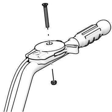
ASSEMBLY HANDLEBARS SUPPORT AND HANDLEBARS (Fig.14) The handlebar support tube (2) has to be screwed up to the motor mower frame (4). In order to perform such operation you have to use the tightening handle (8) you can find already positioned on the tube. Rotate it clockwise. Fix the handlebar (1) to the support tube (2) using the screws. (3) attention! the washers showing the biggest diameter should be positioned in correspondence with the slots. The operator can adjust the handlebar height operating on the screws to make his own job easier (3).
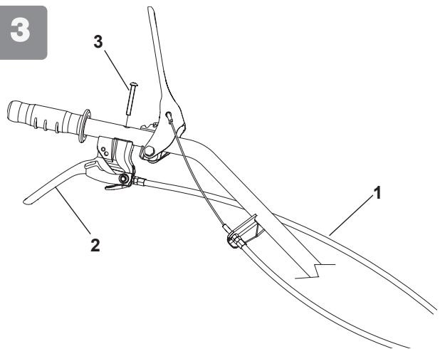
ASSEMBLY CABLE FORWARD SPEED (Fig.3) The driving cable (1) is already linked to the belt stretcher lever of the frame to the lever (2). Please tighten the lever (2) on the handlebar using the screw (3) you can find into the loose parts bag.
ASSEMBLY CABLE FOR BAR CONNECTION (Fig.15) the cable is already linked to the black level placed under the frame and you need to make the cable to pass into the nib place on the side of the frame. Make the cable to pass into the steel ring of the handlebar support (fig.13 part.7) and into the nib hole (2) then into the red lever (4).
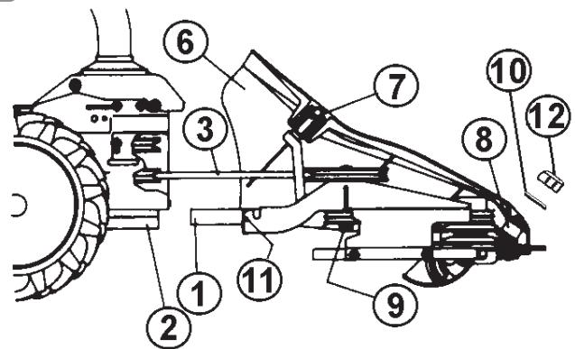
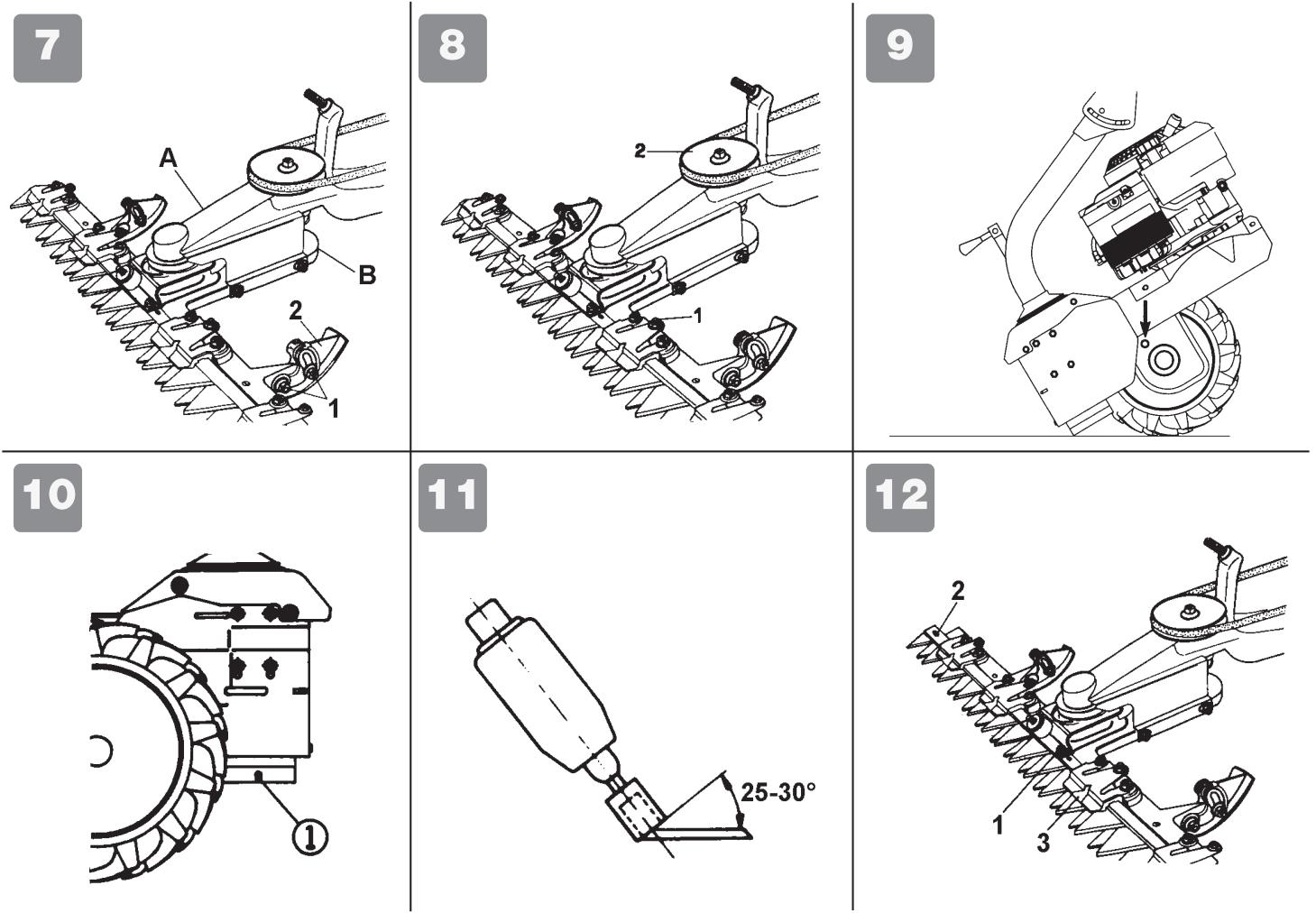
CUTTING BLADE ASSEMBLY+ BAR MOUVEMENT (Fig. 4-4A-7) ATTENTION ! before handling the cutting bar please assembly the protection part you can find inside the packaging box. For protection safety purposes, please always wear a pair of hardy gauntlets. To make the assembly of the cutting blade (A fig.7) device to the unit (B fig. 7) easier we recommend you to perform the work on a work bench. Fig. 4) The cutting mower is equipped with a joint which allow the easy quick connection of the cutting set to the unit. The engine has to be switched off and the unit put in horizontal position: grease the bar pin with engine oil (1) and insert it all the way into its seat (2).
Assemble the belt (3) on the pulley, then on the cutting bar. Assembly the grass separating cover (6) and fix it on the front antivibrating part (8) then on the welded screw (7). Put the washer (10) on the screw and screw it with the nut (12).
Fig. 4A) Position 1 and 2 : turn the handle (13) until you are able to couple the right side spring (14) to the connection (15). Position 2 and 3 : to complete the above coupling, rotate the handle (13) in the opposite direction until you are able to tension the spring (14).
STARTING UP (Fig. 5) ATTENTION!: the scythe mower is delivered with a 4 stroke engine: oil is not included.
The tank has a capacity for about 0,500 kg. and has to be filled in up to the shown level. Anyhow, please always read very carefully the enclosed instruction referring to engine. Put the throttle handle (1) on start position, then switch the engine on. Adjust the handle in order to get to the needed engine revolutions.
In order to connect the cutting bar it is sufficient to rotate the safety catch (3) to the top and to lower the lever (4). When the lever (4) is released, the bar stops.
In order to engage the forward speed it is sufficient to turn down the safety catch (5) and pull the lever (1). When the lever is released (1) the machine stops.
In case you have to face an unforeseen and accidental obstacle, you should immediately leave the two driving levers (2 and 3). When you finished your work, please switch the engine off, and put the throttle handle (1) on stop position.
ADJUSTING AND CONNECTION FOR THE SCYTHING BAR (Fig.5) To increase the belt tension between the unit and the accessories, you should act on the adjusters (2) to make the bar to start scything only when the red lever (4) has crossed half its way. ATTENTION: before lowering the accessories insert red lever (4), you should always unhook the safety lever (4).
BELT- STRETCHER CONTROL ADJUSTMENT (Fig.6) Attention : the motor-mower wheels should start to turn when the driving lever (fig.5 part.1) has crossed half its way. When the mentioned lever is completely pulled, on working position , the belt-stretcher load spring (2) should extend between 6-8 mm. To obtain the am conditions you have to act on the nut (1) set close near the belt-stretcher control.
ADJUSTMEN OF THC SCYTHING BAR HEIGHT (Fig.7) If you need to scythe on uneven grounds it is necessary to adjust the scything bar height. Please follow the instruction: loosen the nut (1), bring the plastic strip (2) to the needed position and tighten the nut. Please perform the operation on both the plastic strips.
CUTTING BLADE REGULATION (Fig. 8) After the blade substitution or after some working hours the knife-guide should be regulated by using means of screws (1) and their locknut. Every time in order to control the regulation you have first to disassemble the hood then slowly make the pulley to turn (2) and then verify if the blades are easily moving.
HANDLEBAR SIDE ADJUSTMENT (Fig. 14) The mower handlebar can be both side and height adjusted. It would be better before starting to work, to regulate the handlebar according to operator needs in order to make the machine easier to handle in every position. The side handlebar adjustment can be obtained on 3 different positions: please follow the steps: turn the lever anticlockwise (8) to detach the clamping regulate the handle in the needed position. Fix the handlebar again turning the lever (8) clockwise and check that teeth/gears should be fully connected.
SERVICE AND GARAGING Keep attention that all the nuts, screws and bolts are tightened in order to guarantee a good machine working on safety conditions. Leave the machine to cool before garaging anyhow don't room it if the tank still contains some fuel as the vapours could reach some blazes or sparks. The fuel tank is to be drained outdoors only. To lower the fire danger, keep the engine, the silencer and the fuel area free from leaves, grass or greasy substances.
GEARBOX (fig.9) lubricating : use SAE 80 Please verify the oil level before switch the engine on. The oil level can be verified unscrewing the cap placed on the side of the gearbox. Please change / check the oil level every 60 working hours.
ATTENTION! The used oil must not be drained into the sewer system or waterworks. In order to prevent any pollution to the water-table. Most garages have used oil deposits, or use the authorized deposits according to your local authority regulations.
TRANSMISSION SCYTHING BAR (Fig. 10) greasing point (1) Important : after every use of the scythe-mower, please clean and grease the scything bar and all parts mechanisms.
ENGINE SERVICING (please read the specific part). The motormower is delivered equipped with a 4 stroke engine, NO OIL is included. Please fill the tank in up to the shown level (capacity about 0,500 kg.). Referring to the oil/viscosity type, please follow the engine producer instructions.
SCYTHING BAR SERVICING : the motormower is undoubtedly one of the most used agricultural equipment and need a good and frequent servicing. We recommend you to clean very deeply after every use. If the machine is not used for long periods it is ESSENTIAL to protect the blade and the bar using some anticorrosive and antioxidant materials. The presence of impurities or foreign bodies on the meadow, damages the teeth sharpening of the scything bar. It is useful to sharpen the blade and check the teeth integrity every 10 hours use, Only if you keep a good sharpening teeth level you can obtain the best grass cut. Furthermore it is good to perform a periodical control and a possible setting up of the “ clearance” of the blade in the sliding supports. In case the machine is equipped with pneumatic wheels . You are kindly requested to periodically verify the inflation pressure level for the tires : the recommended value is 21 PSI ( 1,5 Bar) . However be careful not to exceed the maximum value indicated on the tire itself.
BLADE SHARPENING (Fig. 11) According to the frequency and the type of use, the cutting sections have to be sharpened about every 10 hours working. To obtain a perfect sharpening you need to use and electric sharpening machine (15.000/20.000 turns/minute), grinding-headed with a diameter 25 mm and lenght 35 mm. The blade has to be sharpened from the internal part of the rod to tip.end section using the head grinding. The blade sections have to be sharpened in a 25^ deg. angle.
REPLACEMENT THE SCYTHING BLADE (Fig.12) To remove the top knife to change and sharpen it, remove screws (1) and pull the knife out with a pin push into hole (2). We recommend changing the knife after 2 or 3 sharpenings. The bottom knife should be changed after the cutting knife should be changed after a couple of changes of the upper one. In the meantime you have to change the plastic knife guides (3).
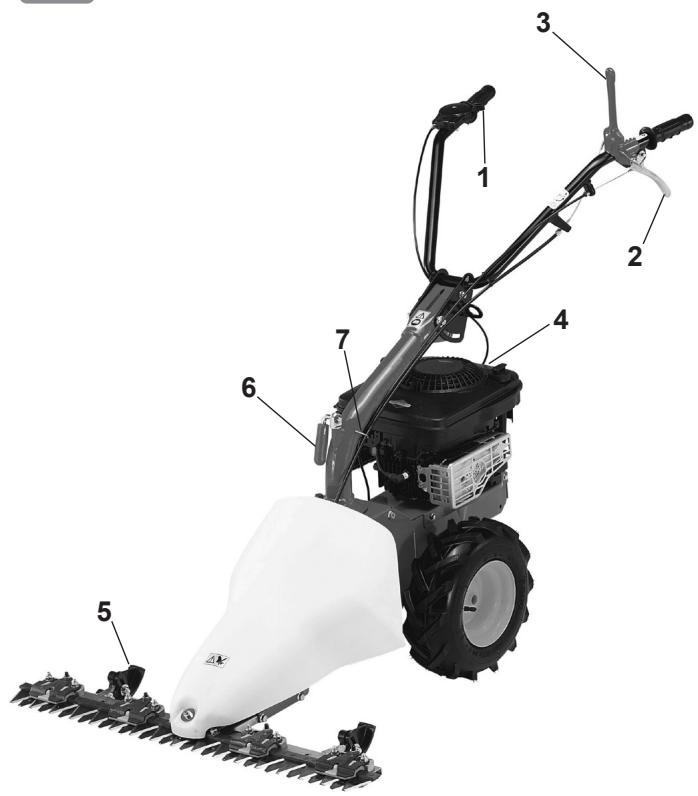
DESCRIPTION (Fig.13) 1) Throttle control 2) Transmission control for driving wheels lever 3) Bar connection driving level 4) Engine 5) Scything bar 6) Lever for the regulation of the side handlebar 7) Steel ring of the handlebar support.
TECHNICAL DATA Track: 430 mm. - Cutting bar width : 870 mm. – Total motor-mower length 1500 mm. – Total motor-mower height 1000 mm. – Wheels: (2) 13x5.00-6 – Mass: 60 kg. For further technical data and details for the engine, please see the enclosed instructions manual.
NOISE AND VIBRATION LEVEL Measured sound power level, Lwa = 94,2 dB (A), with a uncertainty value K = ±1,3 dB (A). Measured sound pressure level with En12733, Leq = 81,4 dB (A), with a uncertainty value K = ±1,1 dB (A). Handlebar vibration in compliance with EN 12733. Level max detected = 10,39 m/s², uncertainty value K = ±5,19 m/s².
FAULT

Before performing any maintenance and clearing work operation, please take the spark-plug cap off.!
| FAULT | FAULT CLEARANCE |
| The engine does not start | check the fuel level, if necessary refuel. |
| check the throttle to be on START position | |
| check the spark-plug connector to be properly attached | |
| check the spark-plug condition and if necessary replace it | |
| check the fuel valve to be in the opened position (only for the models showing such feature) | |
| The engine power goes down | the air filter is dirty – please clean it |
| The grass cut is irregular | sharpen or replace the cutting blade adjust the cutting bar clearance |
| The cutting bar does not work or the wheels are not turning | adjust the cutting bar cable |
| check the wheels to be fasten to the shaft | |
| check the position and the transmission belts position and condition : realign position and/or replace them. | |
| In case you are not able to remedy the defect/damage according to a.m. table, please contact an authorized service center only . | |
Table des matières
Introduction



Brand : EUROSYSTEMS
Model : MFL01
Category : Tiller