MPM01 - Tiller EUROSYSTEMS - Free user manual and instructions
Find the device manual for free MPM01 EUROSYSTEMS in PDF.


| Product type | Tiller |
| Brand | Eurosystems |
| Model | MPM01 |
| Engine | 4-stroke petrol |
| Engine power | 5.5 hp (4 kW) |
| Working width | 55 cm |
| Working depth | 25 cm |
| Number of tines | 4 |
| Working speeds | Forward: 2, Reverse: 1 |
| Dimensions (L x W x H) | 95 x 55 x 85 cm |
| Weight | 38 kg |
| Fuel | Unleaded petrol |
| Tank capacity | 1.5 L |
| Main functions | Digging, tilling, weeding |
| Maintenance and cleaning | Clean after each use, drain fuel for winter storage |
| Safety | Emergency stop, hand protection |
| Spare parts and repairability | Available from Eurosystems dealer |
| Warranty | 2 years |
Frequently Asked Questions - MPM01 EUROSYSTEMS
User questions about MPM01 EUROSYSTEMS
0 question about this device. Answer the ones you know or ask your own.
Ask a new question about this device
Download the instructions for your Tiller in PDF format for free! Find your manual MPM01 - EUROSYSTEMS and take your electronic device back in hand. On this page are published all the documents necessary for the use of your device. MPM01 by EUROSYSTEMS.
USER MANUAL MPM01 EUROSYSTEMS
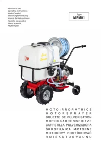
MOTOIRRORATRICE
MOTORSPRAYER
BRUETTE DE PULVERISATION
MOTORKARRENSPRITZE
CARRETILLA PULVERIZADORA
ŠKROPILNICA MOTORNE
MOTOROVÝ POSTŘIKOVAČ
RUISKUTUSVAUNU



5


6

7
8

9

10
11

12

13

14


15
16

17


Manufacturer

Model: xxxx-xxxxxxxxxxxx

Type: xxxxx xxxx | xxxxxxxxxxxxxxx

Nr.: xxxxxxxxxxx-xxxxxx

Weight: xxx kg

Date: aaaa / E

Power: x.xx kW

IT
- Manufacturer identification
- Model
- Product identification code
- Item serial number
- Mass
- Year / Month
- Motor power
- Type of product
FR
- Etichetta carico massimo e pendenza massima consentita.
- Label showing the maximum permissible load and maximum allowed slope.
- Bitte beachten Sie die zulässige Maximalbelastung, sowie die höchstzugelassene Steigung wie auf dem Aufkleber beschrieben.
- Etiquette de charge limite et de la pente maximale permise.
- Etiqueta de carga máxima permitida e inclinación máxima permitida.
- Nalepka z navedbo največje dovoljene obremenitve in največjega dovoljenega nagiba samokolnice.
- Etiketa maximálního zatížení a maximálního povoleného sklonu.
- Maksimikuormituksen ja suurimman sallitun kaltevuuden merkintä.

Label scheme for wheels block/unblock.
Label instructions for tank overturning.
Warning: risk of limb injury. Rotating parts.
4 5 6
1
Attenzione, pericolo!
Warning!
Attention, danger!
Vorsicht, Gefahr!
¡Atención, peligro!
Pozor, nevarnost!
Pozor, nebezpečí!
Varoitus, vaara!
2
Vietato fumare!
Do not smoking!
Défense de fumer !
Rauchen verboten!
¡Prohibido fumar!
Kajenje prepovedano!
Zákaz kouření!
Do not drink the water ! it is not drinkable
Please use protection gauntlets
Wash the hands after every use
thanks for trusting our products and wish you some enjoyable hours with our equipment. We issued the following instructions to ensure a right and correct use of the unit. For such reason we beg you to carefully follow the present working and safety instructions so that the machine could operate with your complete satisfaction and have a long service life.
Before starting the standard production, our machines are very severely tested and during manufacturing they are submitted to severe controls. This means for our customers, and for us, the best guarantee that present product meets the best quality standards. The present unit was put through strict neutral tests in the country where it is manufactured and showed to meet current safety legislation.
To guarantee what above it is necessary to fit the machine only with original components/spare parts. The manufacturer forfeits any claims/warranty right which may arise if the machine is fitted with components other than original spare parts. The unit is subject to changes in design and construction without notice. In order to process customers' technical information and spare parts orders, please always inform about the machine serial number.
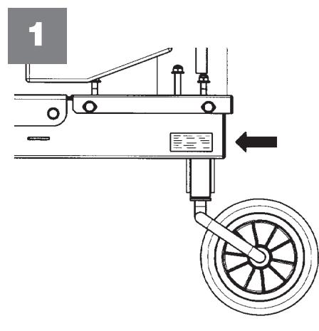
IDENTIFICATION DATA : (FIG. 1) the label with the data of the machine and the serial number is shown on the left side of the motosprayer, under the engine. Note : in case customer/user needs technical help and for spare parts requests , please always state the unit serial number so that we can properly process them.
INSTRUCTIONS FOR USE : the motosprayer has been built for spraying operations purposes. For the machine operations/working only 1 operator is needed who has the responsibility to keep at a safety distance all the people in the surroundings (more than 10 m.from the machine area). Do not use the motosprayer for different applications from the ones for which it has been designed ( and here above described) (i.e. for example : painting with it is illegal). The illegal applications/uses imply the lost of the warranties terms and possible dangers to happen on operator or people in the surroundings.
SAFETY RULES TO FOLLOW : before starting the unit it is necessary to read the present manual and to carefully follow the instructions here contained concerning the pump and the engine use. All the units are equipped with a safety device. Such device causes the clutch disengagement and the consequent stopping of the unit set on forward/reverse speed, the release of the drive control lever. Furthermore such device avoid the engagement of the reverse speed while the forward's is engaged.
INSTRUCTIONS FOR USE :
on the unit and on the present instructions booklet are present notices and indications shown by the present signal which are meaning the presence of a potential ranger. It is worth to use caution for our own safety and for the people in the machine surroundings.
- Persons who are not familiar with the operating manual, as well as children, adolescents under the age of 16 and persons under the influence of alcohol, drugs or medication must not operate the motospaper.
- Please work in the daily light or in a good artificial lighting.
- The chemical products used to irrigate can be dangerous to people or animals. Please carefully check to be sure there are no persons in the surroundings.
-
During working operations, please always wear protective clothes, gloves, goggles, mask, shoes and overalls.
-
Before use, please carefully proceed at a visual control of the tightening of all components, of the machine entirety and the pneus pressure. Please verify in particular the correct clamps tightening.
-
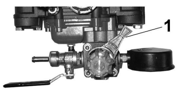
The motosprayer should be used at a max pressure of 30 Bar. If the manometer is showing a higher value compared to the limit, it is necessary to operate/adjust the red handle (Fig. 6 – part. 3) to reduce the pressure: in case of emergency switch immediately the pump off as you may risk to damage the internal gears.
7.Do not use the motosprayer for different applications than the ones here described for which it has been designed, in particular, do not use the motosprayer using liquids different than water (for expl. solvents, gasoline, inflammables, etc...).
- In case of use on slopes it is worth the wheels tightening pawls are inserted in the corresponding pins (Fig. 2 - position n. 3), in order to avoid the unit suddenly to stop. Furthermore, please be careful during the unit displacement and the sprinkling unwinding operations in order to control that any obstacles to be in the neighbourhood, like branches, stakes, wires. Furthermore on slopes please always work uphill or in descent and NEVER crosswise.
-
We recommend to switch the pump intake off (read previous paragraph) if you stop the irrigation for a long period in order to avoid the tank overheat and the decay of the chemical characteristics of the liquid there contained.
-
DO NOT SWITCH ON the machine in enclosed areas and/or not well ventilated as endothermic engines produce carbon monoxide which is lethal to people.
-
Do not move away before having switched the engine off. Do not leave the unit unattended.
12.WARNING! the gasoline is highly flammable. -
Do not fill the gasoline neither in enclosed areas nor with the engines on. Do not smoke and be careful to gasoline leakage from the oil tank.
- In case of leakage do not try to switch the engine on but move the unita way from the dangerous area to avoid the creation of ignition sources and until gasoline fumes are dispelled.
- Properly replace the gas caps and the gasoline case.
13.ATTENTION to the exhaust pipe! the parts near to the pipe can reach 80^ . Please change/replace the worn silencers or defective pipes 14. Engine instructions. please carefully read the instructions booklet enclosed to the engine.
- when finishing the irrigation operation it is worth to wash the equipment, intaking clean water and empty it, then make the pump to work without the suction pipe.
- NEVER waste the chemical residueS in the environment, as they can create pollution problems. Please gather then in a container and dispose of them according to the current legislation norms or to the supplier instructions.
- Any use of the unit, except the listed ones, and/or the fitting of the machine with components other than the original spare parts means to lose the exercise of the right of warranty. The lost of the warranty terms means also the decline of the responsibility from manufacturer's side.
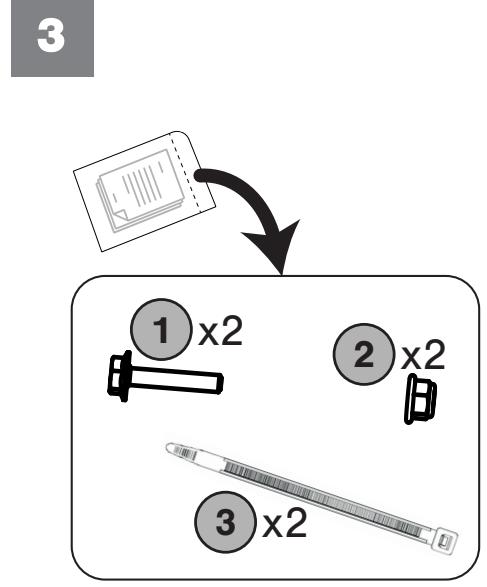
ASSEMBLY (FIG. 3-4) The motospaper is delivered partially unassembled and housed into its packaging. Before to use it is necessary to complete the assembly, therefore it is necessary to fix the hose reel (4) in the corresponding holes on the respective support (5), then fix with screws (1) and nuts (2), previously taken from the accessories bag. Finally join the pipes (6 and 7, 7 and 8) using the two cable ties (3) taken from the accessories bag so that the cables are not an impediment to work.
HOW TO ADJUST THE BELT STRETCHER FOR FORWARD-REVERSE SPEED : (Fig. 13)
-FORWARD SPEED: the wheels have to start working only when the forward control lever 2 has moved halfway its travel. When the lever is completely pulled (working position) and it is therefore at the end of its travel, the load spring of the forward belt strecher must extend for about 6-8 mm (Fig. 13.1).
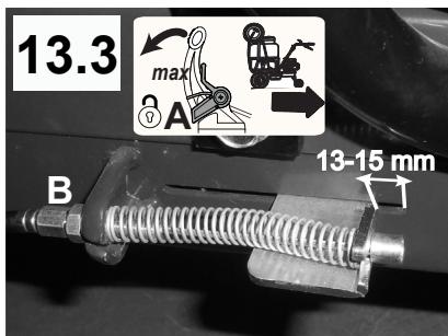
- REVERSE SPEED: Adjust the cable so that when the reverse control lever 3 is at the STOP position (Fig. 5.1), the spring holding plate is in contact with the end of the slot as shown in the figure Fig. 13.2.
When the lever is completely pulled (working position), the load spring of the reverse belt strecher must compress for about 13-15 mm (Fig. 13.3). In order to obtain the am conditions you should adjust the register (B) which is placed near the driving levers area.
TO USE THE MACHINE :
START (FIG. 5) Please position the accelerator lever (1) into position START then switch the engine on firmly pulling the recoil starter handle (4). Once you could get a regular starting, please adjust the RPM acting on the accelerator lever (1). Now, to go forward it is enough to pull the lever (2).
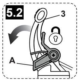
Reverse speed: release the forward control lever (2) and unlock the device (A) in the direction shown by the arrow moving it from the position (Fig. 5.1) to the position (Fig. 5.2). Pull towards you the lever (3) until the machine starts to draw back.
ATTENTION: It is important that when the device (A) is in the locked position (Fig. 5.1) the machine does not move. If this does not happen, adjust appropriately the cables, as explained in the ADJUSTMENTS chapter (Fig. 13).
WHEELS INSERTING (3 POSITIONS) DEVICE : (Fig.2) – The motospaper is equipped with a special device named “ FORK – 3 POSITIONS”. In position 1 ( free) the wheel is free turning on the shaft in order to allow the machine tom ove even if the engine is switched off ( for example in case the operator wants to drive the unit out from garaging as it is better to avoid to switch the engine on in close areas or not well ventilated and the exhaust gas is dangerous).
In position 2 (stop) the wheel is integral with the shaft, and it i sto be considered as a driving wheel, i.e. ready to work, which is normally the most used way. Such position is COMPULSORY when you are using the motosprayer on slopes. Position 3 (semi-differential) the wheel can move for about 1 free turn on the shaft in order to allow the reversal of speed.
ATTENTION ! All the actions performed on the 3 positions fork should be done when the engine is switched off and on a flat surface.
SPRAYING (FIG. 6-7-8) The motospayer had been designed for a single use and it is not allowed to perform spraying operations when the machine moves. You need to switch the engine on to go near the area to spray (SEE CHAPTER: HOW TO USE THE MACHINE) and insert the device intake using the proper lever (1) and turn it on position "I": this way you shall start a continuous flow cycle of liquid into the tank. Such liquid is passing into the pump and comes back into the tank again. It IS necessary to wait for a while that the am cycle is starting then you need to put the tap on "ON" position and adjust the requested service pressure using the red handle (3). The reached level is shown by the manometer (4).
Now you can start spraying : hold the nozzle (5) and press the lever (6). A slight pressure will make the nebulized liquid to come out , while pressing the lever all the way you will see a more powerful jet/stream. When the operator finishes his job you should put the nozzle into the corresponding housing (7) , put the lever (1) on position “O” and switch the engine off.
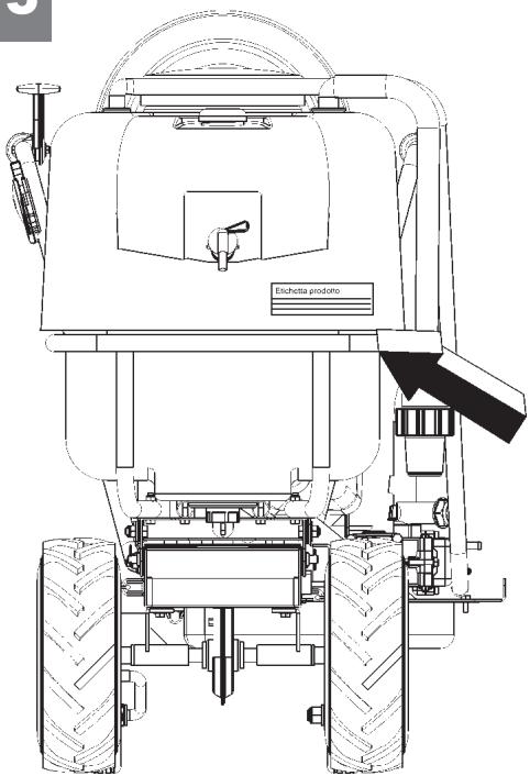
IDENTIFICATION DATA FOR THE PRODUCT IN USE (FIG. 15) On the unit it is installed a label-holder with its own label where the user is obliged to show the name of the pesticide he is using, such label holder is placed on the front side of the tank.
HANDWASHING SYSTEM (FIG. 16) The unit is equipped with an independent tank (A) capacity di 10 Lt which is used to rinse the hands or other parts of the body that accidentally come in contact with the product in use. In order to make the water to come out from the tank it is necessary to rotate the lever (1) placed on the tap (2) clockwise by 180^ . To stop the water please perform the a.m. operation in reverse.
IMPORTANT! TANK (A) IT IS ALLOWED TO PUT WATER ONLY.
RANGE AND TYPE OF SPRAYER, and NOZZLE, FILTER USED:
Sprayer: Tube steel lance with nozzle stainless ∅1.5 mm, use between 15-60 Atm (standard).
You can use any type of nozzle (expl simple miter nozzle etc., It is important that its application range to be between 15-60 Atm.
Head for turbo nozzle lever: Nozzle ∅1.5 mm, ceramic, may also be used with nozzle holes that varies from a minimum of ∅1 mm to a maximum of ∅3 mm. The combination of the above mentioned nozzle, with head turbo nozzle with ∅1.5 mm to 30 bar, it has a range of up to 9 meters; if at the same pressure (30 bar) can be adopted nozzles with greater holes than ∅1.5 mm, the range/throw increases. Example: 30 Bar, nozzle with ∅3 mm hole, you get a range of 11 meters. Group filter: filtering capacity 60 l/min., Thread fitting 1 "1/4, 18 mesh
SERVICING: During all services operations, cleaning and assembly of the accessories, it is necessary to switch the pipet of the engine sparkling plug off. Before every use, please verify the seal of the connectors and gaskets in order to avoid any liquid leaks and consequent pollution danger. Please also check, from time to time, the pump oil level and, if it is necessary, please fill it in. (see the pump instructions booklet here enclosed). When you screw the cap up, please take care not to tighten it too much in order to avoid the thread to damage.
CLEANING THE IRRORATION SYSTEM FILTER (Fig. 17 and 18): The spraying system is equipped with a filter (1), placed in front of the pump. If it is necessary to drain the filter, with the engine off, unscrew the yellow cap (2), pressing at the same time upwards.
ATTENTION! With this operation the liquid contained in the filter will be emptied, prepare in advance a suitable container to prevent spills.
If a complete cleaning is necessary, remove the filter element (4), unscrewing the ring nut (3).
ATTENTION! Before resuming work, make sure you have reassembled the filter correctly, following the previous instructions in reverse.
GARAGING AND RECURRING SERVICING: Please keep all the nuts, the washers and the screws well tightened in order to allow the machine to properly/safety working. Please make the unit to cool before garaging it and, anyhow, do not leave gasoline in the tank in inside areas where vapours can come into contact sparks and/or flames.
To reduce the danger of fire to break out, please keep the engine, the silencer and the gasoline stocking area free from leaves, grass or greasy materials. Please proceed the here under mentioned operations (with the term “hours” we mean the working hours of the machine).
GEARBOX (Fig. 14)
OIL LEVEL CONTROL : Lubricating oil : please use oil SAE 80. Please verify the oil level every 60 hours . Please put the machine on level land, unscrew the cap (1) and check the oil to be at a hole lower side in case it is necessary to restore the oil level , fill it in from the same hole up to the oil quantity comes out. Then screw up the cap again.
OIL CHANGE : please change the oil every 150 hours. The oil discharge should be performed when the unit is still warm. Unscrew the cap (1), incline the unit to completely empty it, then, fill it in using the same hole (1) up to the oil quantità starts to come out. Then screw the cap again.
Attention : the waste oil is a polluting material. Please do not waste it in the surroundings, but call to specialized gathering centres.
TROUBLES AND REMEDIES : please see the pump instructions booklet.
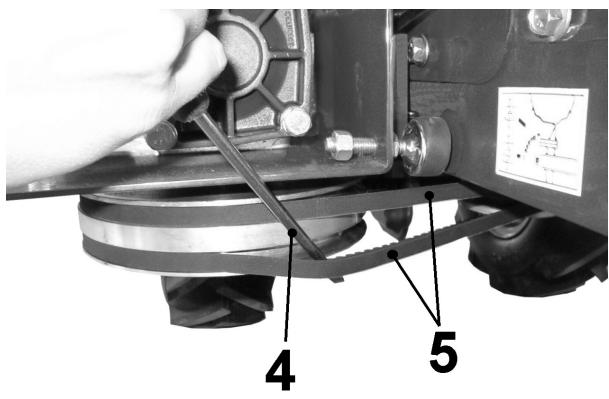
DISASSEMBLY OF THE PUMP-TANK SET : (FIG. 9-10-11-12) In case it is necessary to disassemble the spraying set composed of the pump and the tank (for example to change it with other accessories). It is necessari to remove the belts protection cover (part.1), unscrewing the screw (2) and taking out the end (3) from the frame slot. The using a punch (4) make the belts to come out (5) from pulley seats and, following, press the handle (6) and meke the set to rotate forward. To complete the disassembly operations it is enough, on both sides of the machine, to remove the pin (7) and press, in the same time, using a punch on the pivots (8) in order to allow the spraying set unclamping.
TECHNICAL SPECIFICATIONS : 2 gears gearbox( 1 forward + 1 reverse) – Endless screw transmission in oil bath + belts - tank lt. 120 with filter – Membrane pump RPM max 700 – Pressure max 30 Bar - max capacity : 20 lt/minute - Winding tube support equipped with 25 mt tube + hose pipe.
NOISE AND VIBRATION LEVELS : acoustic power value to operator's ear, EN ISO 3744:2010, Lpa = 81,6 dB(A) (79,1 dBA in working conditions), with a uncertainty value K = ±1,1 dB(A). Acoustic power value according to EN ISO 11201:2010, Lwa = 93,8 dBA, with a uncertainty value K = ±1,3 dB(A). Average vibration value for the handlebars during transport, according to EN ISO 20643:2012, i.e., 6,38 m/s², with a uncertainty value K = ±3,19 m/s².
ACCESSORIES : standard tank complete of plate, handle and quick camping device. The snow front blade with adjusting handle. Snow chains pair for pneumatic wheels. Sheet platform cm. 59x81 equipped with a plastic collector.
INTRODUCTION
Brand : EUROSYSTEMS
Model : MPM01
Category : Tiller