LYN300 - Garage Door Motor System CHAMBERLAIN - Free user manual and instructions
Find the device manual for free LYN300 CHAMBERLAIN in PDF.
User questions about LYN300 CHAMBERLAIN
0 question about this device. Answer the ones you know or ask your own.
Ask a new question about this device
Download the instructions for your Garage Door Motor System in PDF format for free! Find your manual LYN300 - CHAMBERLAIN and take your electronic device back in hand. On this page are published all the documents necessary for the use of your device. LYN300 by CHAMBERLAIN.
USER MANUAL LYN300 CHAMBERLAIN
Manager, Regulatory Affairs
Chamberlain GmbH
D-66793 Saarwellingen
January, 2008


VEUILLEZ TOUT D'ABORD LIRE CES REGLES DE SECURITE IMPORTANTES


Page 2-3, Figure 5 A-D
Page 3, Figure 7 A-B
Câblage :
Page 3, Figure 8
Manager, Regulatory Affairs
Chamberlain GmbH
D-66793 Saarwellingen
January, 2008

BaBaa P. KeckhoH
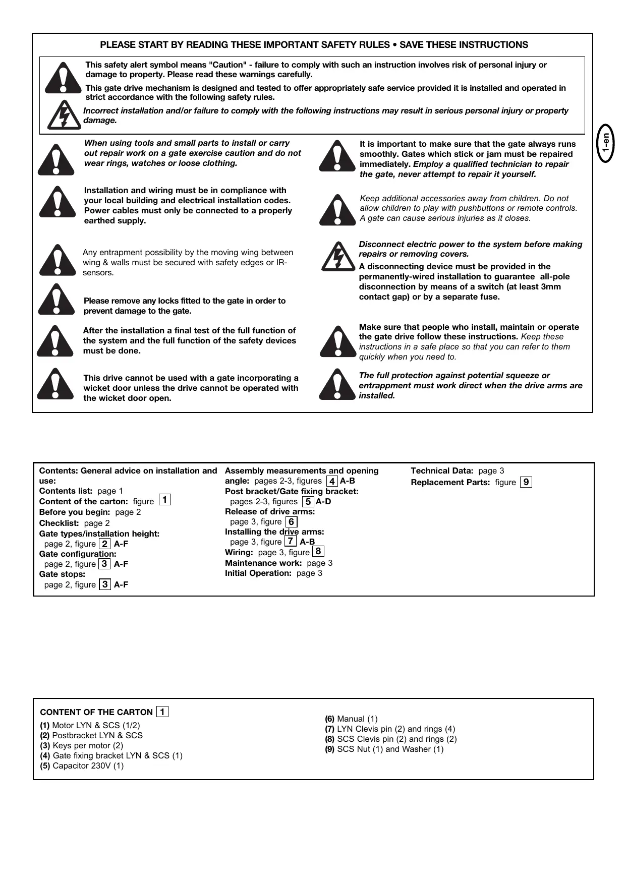
PLEASE START BY READING THESE IMPORTANT SAFETY RULES • SAVE THESE INSTRUCTIONS


This safety alert symbol means "Caution" - failure to comply with such an instruction involves risk of personal injury or damage to property. Please read these warnings carefully.
This gate drive mechanism is designed and tested to offer appropriately safe service provided it is installed and operated in strict accordance with the following safety rules.
Incorrect installation and/or failure to comply with the following instructions may result in serious personal injury or property damage.

When using tools and small parts to install or carry out repair work on a gate exercise caution and do not wear rings, watches or loose clothing.

It is important to make sure that the gate always runs smoothly. Gates which stick or jam must be repaired immediately. Employ a qualified technician to repair the gate, never attempt to repair it yourself.

Installation and wiring must be in compliance with your local building and electrical installation codes. Power cables must only be connected to a properly earthed supply.

Keep additional accessories away from children. Do not allow children to play with pushbuttons or remote controls. A gate can cause serious injuries as it closes.

Any entrapment possibility by the moving wing between wing & walls must be secured with safety edges or IR-sensors.

Disconnect electric power to the system before making repairs or removing covers.

Please remove any locks fitted to the gate in order to prevent damage to the gate.
A disconnecting device must be provided in the permanently-wired installation to guarantee all-pole disconnection by means of a switch (at least 3mm contact gap) or by a separate fuse.

After the installation a final test of the full function of the system and the full function of the safety devices must be done.

Make sure that people who install, maintain or operate the gate drive follow these instructions. Keep these instructions in a safe place so that you can refer to them quickly when you need to.

This drive cannot be used with a gate incorporating a wicket door unless the drive cannot be operated with the wicket door open.

The full protection against potential squeeze or entrappment must work direct when the drive arms are installed.
Contents: General advice on installation and use:
Contents list: page 1
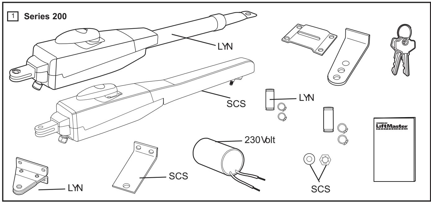
Content of the carton: figure 1
Before you begin: page 2
Checklist: page 2
Gate types/installation height:
page 2, figure 2 A-F
Gate configuration:
page 2, figure 3 A-F
Gate stops:
page 2, figure 3 A-F
Assembly measurements and opening
angle: pages 2-3, figures A-B
Post bracket/Gate fixing bracket:
pages 2-3, figures 5 A-D
Release of drive arms:
page 3, figure 6
Installing the drive arms:
page 3, figure 7 A-B
Wiring: page 3, figure 8
Maintenance work: page 3
Initial Operation: page 3
Technical Data: page 3
Replacement Parts: figure 9
CONTENT OF THE CARTON 1
(1) Motor LYN & SCS (1/2)
(2) Postbracket LYN & SCS
(3) Keys per motor (2)
(4) Gate fixing bracket LYN & SCS (1)
(5) Capacitor 230V (1)
(6) Manual (1)
(7) LYN Clevis pin (2) and rings (4)
(8) SCS Clevis pin (2) and rings (2)
(9) SCS Nut (1) and Washer (1)
BEFORE YOU BEGIN
The drive mechanism needs room to the side permitting correct installation of drive arms. Please make sure that this is available. Gates affected by high wind loads must also be protected by an (electric) lock.
There are many factors to consider when choosing the right drive mechanism. Assuming that a gate functions properly, "startup" is the most difficult phase, once the gate is in motion, significantly less force is usually required to move it.
- Gate size: Gate size is a very important factor. Wind can brake or distort the gate, thereby increasing the amount of force needed to move it considerably.
- Gate weight: The weight of the gate in not as relevant as the size.
- Effect of temperature: Low outdoor temperatures can make initial startup more difficult (changes in the ground, etc.) or even prevent it. High outdoor temperatures along with frequent use can trigger thermal protection prematurely (approx. 135^ ). (Only in the case of 230 volt drives).
- Betriebsfrequenz/Einschaltdauer: 230 volt drive mechanisms are designed for a maximum operating time (running time) of approximately 30% (e.g. 30% during any one hour). 24 volt drives can run permanently.
IMPORTANT: 230 volt drive mechanism is not designed to operate continuously at its maximum operating time (non-stop operation). Otherwise the drive mechanism becomes too hot and switches off until it cools down to the switch-on temperature. The outdoor temperature and the gate are important parameters that affect the actual operating time.
INSTALLATION CHECKLIST - PREPARATIONS
Check the carton contents and read the instructions carefully. Make sure your gate equipment operates perfectly. The gate must run evenly and smoothly and must not stick at any point. Remember that the ground level may be several centimeters higher in winter. The gate must be stable and as free of backlash as possible in order to prevent any unwanted to and fro movement. The more smoothly the gate leaf runs, the more sensitive the force adjustment must be.
Note down any materials you still need and obtain them before starting to install. Heavy-duty plugs, bolts, gate stops, cables, distribution boxes, tools, etc.
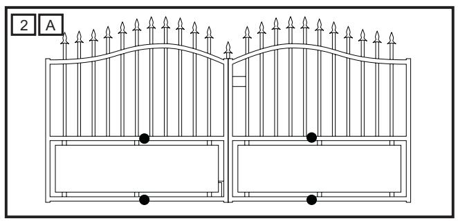
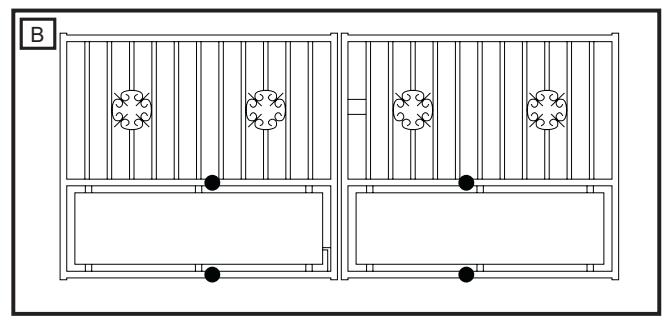
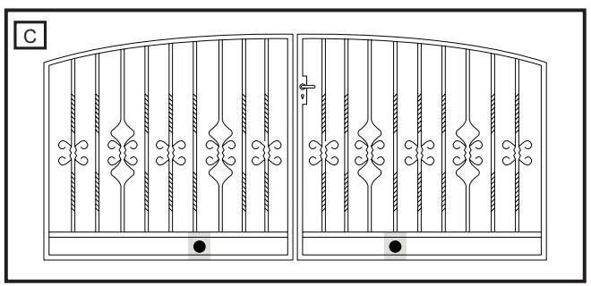
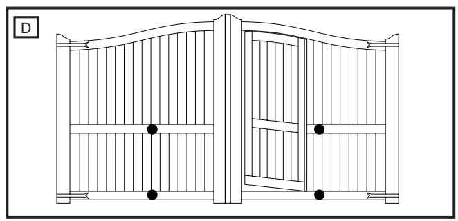
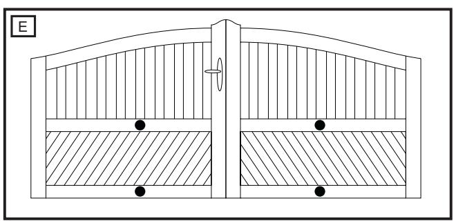
GATE TYPES 2
The gate type determines the location where the drive mechanism is installed. If the gate stop is on the ground, the drive mechanism must also be installed at a height that is as low as possible so that it cannot twist the gate. Use only parts of the gate frame for fixing purposes.
TYPE A, B, C
For steel gates, the gate fitting must be attached to the main frame. If you are uncertain whether the available support is sufficiently stable, reinforce it.
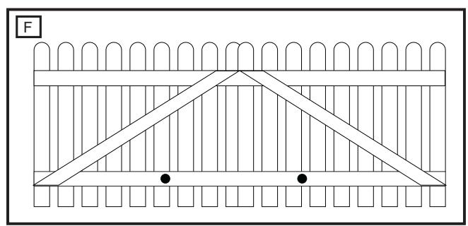
TYPE D, E, F
In the case of wooden gates, the gate fitting must be through bolted. It is advisable to fit a plate from the outside so that the fixing brackets cannot become loose over time. Thin wooden gates must also be reinforced in order to withstand the stresses encountered (e.g. type F).
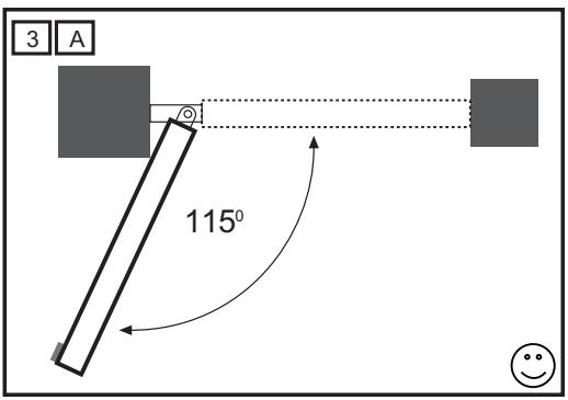
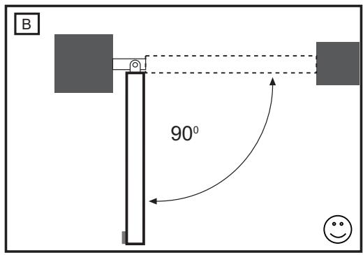
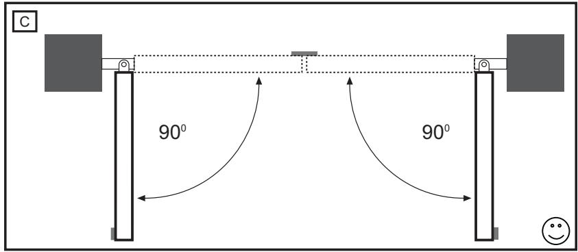
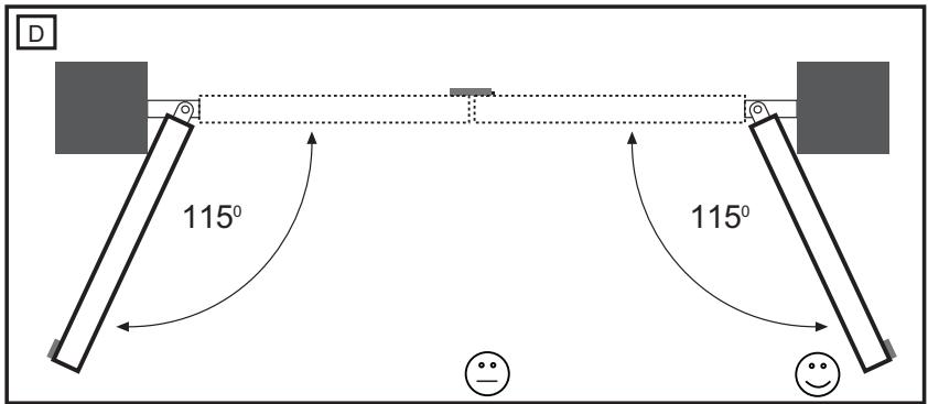
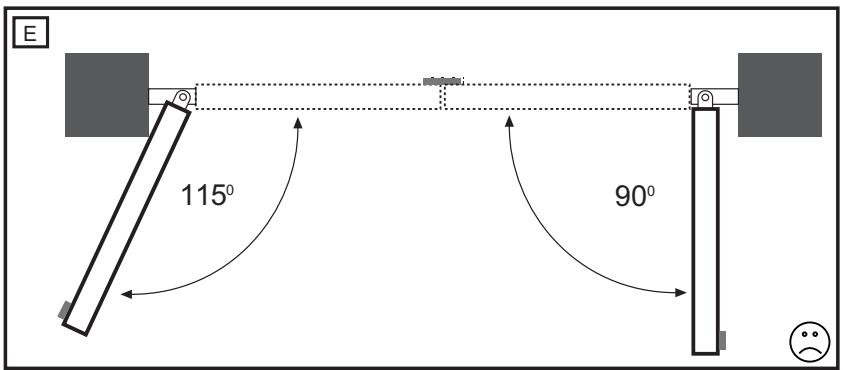
How far must the gate leaf open?
90 degrees or up to 115 degrees. An opening angle in excess of 115 degrees is possible to a limited extent but is not recommended. Reason: the drive mechanism always runs at the same speed. The further the gate has to be opened, the faster the gate leaf must travel. Movement becomes more erratic and this subjects the fittings and gate to extreme stresses.
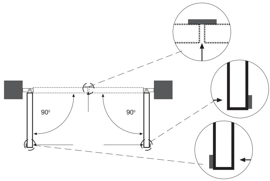
For gates without limit switches: Non-identical opening angles cause one drive mechanism to reach its destination first, but continues to run, thereby forcing the gate up against the gate stop until the other motor eventually reaches its end position (see figure 3A-F).
Tip for professionals: The time taken to reach the limit stop can be controlled by deliberately selecting different A and B dimensions (left + right). However, this method of installing subjects the fittings to high stresses and can cause the gate to run erratically. It is recommended that only experienced gate installers adopt this method.
IMPORTANT If the gate opens towards a wall, there is a risk of entrapment. Should the distance between the wall and the open gate be less than 200mm , this area must later be secured via a light barrier or contact strip.
GATE STOPS 4
A SWING GATE NEEDS A FIXED GATE STOP IN BOTH THE OPEN AND CLOSE DIRECTIONS. Gate stops save wear and tear on the drive mechanism, gate and fittings. Operating a gate without fixed limit stops results in poor performance. It is often dangerous, leads to premature wear and voids your warranty!
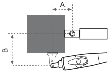
POST FIXING BRACKET 5
Choosing the correct location for the post fixing bracket has a decisive impact on the subsequent functioning of the system. It determines the distance between the motor's centre of motion and the gate's centre of motion and hence the opening angle. These dimensions are referred to as dimension A and dimension B. Do not underestimate the effect that these dimensions have on correct functioning and running. Try and achieve the best dimension for your opening angle, as precisely as possible and suitable for all circumstances. See Table (figure 3F) for dimensions A/B.
If the post is not wide enough, an extension piece must be fitted to it (figure 5B). If the post is too thick, cut out part of it to make it thinner (figure 5D) or offset the gate (figure 5C).
To obtain ideal dimensions, it may be necessary to shorten or lengthen the supplied hinge plate. In the case of gates that are to be custom made, if the gate hinges are fitted on the posts appropriately, it is possible to influence dimensions A and B. Before the final mounting dimensions are determined, you should always check whether or not there is any possibility that the corner of the drive mechanism will hit the post as the gate swings.
INSTALLATION: The drive mechanism exerts considerable force against the post. Usually, acceptable mounting dimensions are obtained if the supplied hinge plate is welded directly onto the post. In the case of thick stone or concrete posts, the hinge must be welded to a base plate and attached so that the plugs cannot work loose during operation. Heavy-duty plugs where a threaded rod is bonded into the masonry stress-free are more suitable for this purpose than steel or plastic straddling plugs. In the case of brickwork pillars, bolt on a relatively large steel plate that covers several bricks and then weld the hinge plate to it. An angle plate attached over the corner of the post is also a good means of fixing the operators.
ACCESSORY TIP 1: For round posts an accessory fitting can be mounted that simplifies the setting of the A/B dimension (model 207917).
ACCESSORY TIP 2: For gates swinging outwards a special fitting can be ordered.
GATE FITTING 5
The gate fitting must be installed so that it is horizontal relative to the post bracket. The distance between the gate bracket and post bracket is referred to as the "arm span". When the gate is closed, the drive mechanism is 99% extended. When the gate is opened, the drive mechanism is 1% extended. Fully retracting or extending the plunger/spindle in operation (with gate) damages the drive mechanism and voids the warranty. It is absolutely imperative to comply with the required arm span under all circumstances! For steel gates, fixings should be welded on or through bolted. When through bolting the gate, use large washers or a plate on the other side. The drive mechanism exerts an extremely high force on this joint. Fixings must be through bolted for wooden gates. Wood deflects under load and the bolt will become loose. Due to movement caused by repeated loading, the wood deflects more and more until the gate no longer closes correctly and has to be repaired. Fit a reinforcing plate from the outside and one on the inside so that the wood cannot deflect and the joint cannot become loose. Thin wooden gates without a metal frame must also be reinforced in order to withstand continuous stresses (e.g. type F).
RELEASE 6
The drive mechanism can be released. The gate can then be opened and operated manually (power failure). With a new drive mechanism, the release action may sometimes feel stiff/jerky. This is normal and has no effect on function.
Release: Insert the key in the cylinder lock and turn it 180 degrees. Then turn the release lever 180 degrees - done!
Engage: Turn the lever clockwise. As soon as the gate moves or the drive runs, the gear locks again. Use the lock to protect the lever against unauthorized release.
INSTALLING THE DRIVE ARMS
Release the drive. Push the released drive onto the fittings and secure it by using the supplied bolts, nuts and rings.
"If the centre or inner hole, on the hinge plate, is used to fix the post fixing bracket you MUST cut away the remaining section of the hinge plate before activating the arms. Failure to do so will result in breaking the fixing bracket".
Do not use a hammer when you mount the operator on the bracket.
WIRING 7
230 VOLT: The 4-pole connecting cable is approx. 80~cm long and is laid in a curve to the controller or a watertight distribution box located above ground. An approved cable is permanently installed from the distribution box onwards. The capacitor can be connected inside the distribution box or in the controller.
Connection: Connect the capacitor across terminals OP and CL. OP and COM produce rotation direction A. CL and COM produce reversed direction of rotation. Always remember to earth the installation (figure 7B).
24 VOLT: The connecting cable has 6 wires, is approx. 80~cm long and is run in a curve to the control unit or to a watertight distribution box located above ground. A permanent connection is formed from the distributor box via an appropriate cable.
Connection: See control unit instructions.
Cable colours: Brown/Green/White/Yellow=sensors Blue/Red:24 volt motor.
ACCESSORY TIP: Extension cable LA400-JB40
Contains:
(1) 12m cable with terminals
(1) Distribution box IP65
(2) Strain relief PG 13,5
(1) Mounting material
INIATIAL OPERATION
Check functionality in a disengaged state with the hand on the gate. Initial electrical operation is only possible with a suitable control unit that can be purchased as an accessory. Ensure at all times that mechanical and electrical safety instructions applying to the given installation are complied with.
Should the force of the moving wing at its closing edge be higher than 400N, then additional safety facilities (light barrier, contact strip) must be used. Any safety facilities must comply with the requirements set out in EN60335-2-103.
MAINTENANCE WORK
The drive mechanism is maintenance free. Check that the gate fittings and the drive mechanism are securely fixed at regular intervals (monthly). Release the drive and check that the gate functions properly. Unless the gate runs smoothly it will not operate correctly with the drive mechanism. The drive cannot eliminate the problems caused by a gate that does not work satisfactorily.
24Volt drives: also see owners manual of Electronic Control.
TECHNICAL DATA
230Volt
Mains supply (Motor) 220 - 240 Volt/ 50Hz
Current consumption 1.2A
Power consumption 280W
Capacitor 6.3uF
Max. gate width
Max. gate weight 250kg
Protection Class I - IP 44
Connecting cable H07RN-F / 80cm
Rated Thrust 250N
Travel Speed 20mm/s LYN300, SCS300 12mm/s LYN400
Rated operating time 4 Minuten
Temperature -20°C up to + 55°C
24Volt
Mains supply (Motor) 220-240Volt/50Hz
Current consumption 2A
Power consumption 48W
Max. gate width 2.5m LYN300
4.0m LYN400
3.0m SCS300
Max. gate weight 250kg
Protection Class I - IP 44
Force (nominal) 250N
Travel Speed variabel
Opening time 90^ sec. approx. 12 LYN300
approx. 14 LYN400
approx. 10 SCS300
Temperature -20°C up to + 55°C
Declaration of Conformity
Automatic Gate Opener Models LYN300 Series, LYN400 Series, SCS300 Series are in conformity to the applicable
sections of StandardsEN300220-3 • EN55014 • EN61000-3 • EN60555, EN60335-1 • ETS 300 683 • EN60335-1: 2002 • EN60335-2-103: 2003 • EN55014-1: 2000 + A1 + A2 •
EN55014-2: 2001 • EN61000-3-2: 2000 • EN61000-3-3: 1995 + A1 • EN 301 489-3, V1.3.1 • EN 300 220-3 V1.1.1 • EN 13241-1
per the provisions & all amendments
of the EU Directives 2006/95/EC, 2004/108/EC, 1999/5/EG
Declaration of Incorporation
Automatic Gate Opener Models, when installed and maintained according to all the Manufacturer's instructions in combination with a Gate, which has also been installed and maintained according to all the Manufacturer's instructions, meets the provisions of EU Directive 89/392/EEC and all amendments.
I, the undersigned, hereby declare that the equipment specified above and any accessory listed in the manual conforms to the above Directives and Standards.
B.P.Kelkhoff
Manager, Regulatory Affairs Chamberlain GmbH
D-66793 Saarwellingen January, 2008

Baibaa P. KeckhoH
NEJPRVE SI PREOTETATATO DULEZITÁ PRAVIDLA BEZPEONOSTI

2006/95/EC, 2004/108/EC, 1999/5/EG
Zavrečne prohlášeni
Manager, Regulatory Affairs
Chamberlain GmbH
D-66793 Saarwellingen
January, 2008

BaIbIa P.KeLkhOH
Manager, Regulatory Affairs
Chamberlain GmbH
D-66793 Saarwellingen
January, 2008

Dabala P. KeckhoH
EKEINHSTE DIABAZONTA\* TOY\* NAPAKAT HMANTIKOY\* KANONE\* A A EIA\*

Opiéva npoεiδoiointika ouμθa oημaiouv "Ppooxh": av δεν npnoεte autεc tiπoεiδoioηεic, iωc npokλθouv tpaumaiouoi ὀικες ημiες. NapaKaIoUe δiaβατε με npooxη autεc ti πoεiδoioηει.

Autoc o autopatiooic ±b uac kataokuaotei kai eeyxtheta, wote n ykataotaon kai npnou vau kaotavtai ikavoiniTka aopaaleic movov uno kaetotwnc npouc oumuopwoon c touc akolououc kavoce aopaaleiac.
Eav o npakatw kavovc aopaleias dev npouvtai, npoei va npoknboov obaopo tpaumatoi n ulkec zneic.

Kata to xeipioo epyaieiw kai iikpw avtkeiEvw, npenei va eiTE npooekTKoi kai va myn vpate dxauia, oouapikia, n pixa pouxa, otav npobaivee OE epyaicc ykataaonn n tioiopthetaosuac.

H diatae tonoetanctwv nektpikw kawdiw npenei va eiva oupwny tis tonike oikodoukec kai nektpoloyieknpoiaypaec. To nekkokalawio npenei va ouvdeetae kalaaa yeiomega doktuo manto Eouoiobotnevo kai Exiidemuve nekptofoyo.

Kata n ouvapmoIoyon, to KIOUevo Mepoc npen1 va nepikkEiTai mTaTu wv Tmuaw Nou npiiaalouv to kTIpO (n.x. evac Toixoc), dtio npen1va aauBavetau unoyn n KIVON NOU KAVcTo KIOUevo Mepoc KaTAt aoiyma.

ApaieoTe ola ta laouketa nou exouv npoaapooTe i otnv 3upa, pokeievou va anopveuxtuyov znua otn 3upa.
Méta tyn yekataoan, npéi va eλeyythei av o unxaviogc exei puθiortei owta kai otio autoptiaooc, to ouotnma aopaaieiac kai to Eekieiodomega ektaKTnc avayknc λεitoupyouv ωσtá.

Manager, Regulatory Affairs Chamberlain GmbH
D-66793 Saarwellingen January, 2008

Dabbaia P. Keckhoft
KEZDJE A JELEN FONTOS BIZTONSÁGÍ SZABÁLYOK ELOLVASÁSÁVAL

Manager, Regulatory Affairs
Chamberlain GmbH
D-66793 Saarwellingen
January, 2008

Babara P. Keckhoft
PRIJE POÇETKA PROÇITAJTE OVA VAŽNA SIGURNOSNA PRAVILA

Ovi symboli upozorenja označavaju rijec "Pažnja!", poziv za obracanje pažnje, jer njihovo nepostivanje moze prouzrokovati oštecenje ljudskog zdravlja ili materijalnu šetu. Molimo da pročitate ova upozorenja pažljivo.

Ovaj pogonski mehanizam za kapiju konstruiran je i testiran takdo prilikom instalacije i upotrebe uz tocno poštivanje.
pravila bezbjednosti osigurava primjerenu bezbjednost.
Manager, Regulatory Affairs
Chamberlain GmbH
D-66793 Saarwellingen
January, 2008

Barbosa P. KeckhoH
PER PRIMA COSA LEGGERE QUESTE IMPORTANTI NORME DI SICUREZZA!

cancello 4,0m LYN400
3,0m SCS300
cancello 4,0m LYN400
3,0m SCS300
Manager, Regulatory Affairs
Chamberlain GmbH
D-66793 Saarwellingen
January, 2008


BEGIN MET HET LEZEN VAN DEZE BELANGRIJKE VEILIGHEIDSINSTRUCTIES!


Manager, Regulatory Affairs
Chamberlain GmbH
D-66793 Saarwellingen
January, 2008


COMECE POR LER ESTAS NORMAS DE SEGURANÇA IMPORTANTES

Ligaoa rede (motor) 220-240V/50Hz
Tensao do motor 24V
Consumo de corrente 2A
Manager, Regulatory Affairs
Chamberlain GmbH
D-66793 Saarwellingen
January, 2008

BaIbIa P.KeLkhOHT
PROSZE ROZPOCZÁC OD PRZECZYTANIA TYCH WAZNYCH ZASAD DOTYCZACYCH BEZPIECZENTWA


INFORMACJE POCZATKOWE
.2006/95/EC, 2004/108/EC, 1999/5/WE
Manager, Regulatory Affairs
Chamberlain GmbH
D-66793 Saarwellingen
January, 2008

Baibaa P. Keckhoft
IPEED HauJOM PABOT IPOUHTAITE 3TN BAXHbIE IPIPABUNIA TEXHNK Be3OPIACHOCTN

3Tn npedynpexkaioe cmbolbl o3haaot "BhimaHne", obaeHne K Baewemy BhimaHIO, taK kak nx Heco6IIOJeHne MORNo 6bl npuHHb Tb bpe 3doPobBIO yelOBeka nll MaTePnaHbHy uep6.

IoxaJyucta, BHMaTeJbHo npOHTaTe 3TN npEduPpeKdHnA.
Данны пивор BОРТ сКОнстурован И OTТСТИРов ТАКИМ 6БАМ,ЧTOБП пи CBоЕ уCTAHOBKE И NCПОЛьЗВОВAHIM (при ТOTHOM CO6ЛIODEнIN ПраВЛ TExHUNK 6e3ONaCHOCHT) ON IpeДОCTaBJI 6bl NOЛьЗВATEJILO OTHOCITIELHHyO 6e3ONaCHOCtB.
Itorom Heco6IOeHnHaCTOaIX npabIN TexHKn 6e3OnacHOCT MoKcT 6bITb BpeI, npuHHeHbI 3dOpOBbIO IIOeHJIn MaTePnaJIbHbI yuep6.

HaKJaKa CToKa/HaKJaKa BOpO: cTp. 2-3, pncyHOK5A-D
ДеблOKироване KOHCoJN npuBoDA: cTp.3,pncyHOK 6
MoHTaX KOHcOJI npNBOJa: CTp. 3, pncyHOK 7A-B
Ppoklaika ka6enei: ctp.3,pncyHOK 8
Texo6cnyxmbaHne: ctp.3
NepBoe BkIouHeHne: cTp.3
TexHnueckne xapaKTepeNCTnKn: cTp. 3
3anYactn: pncyHOK 9

CoedePxHmoe Hnika 1
(1)Пивов LYN & SCS (1/2)
(2) Haujaika cTojka LYN & SCS
(3) KIIOU HaCToRaUM (2)
(4) Hακλακα BopoT LYN & SCS (1)
(5) KoHdEhCaTop 230V (1)
(6)Инструкши no moHTaxy (1)
(7) LYN BOnTbI (2) n KOnJIbua (4)
(8) SCS Bontb1 (2) u konbca (2)
(9) SCS Fatka (1) u Lza6a (1)
IPEXDE, YEM HAYHETE PABOTATb
IotpbeJMaMoUHocTb 280W
KoHdEHCatOp 6,3uF
Makc. shinpina BOPOT 2,5m LYN300
4,0m LYN400
3,0m SCS300
Makc. Macca BopoT 250kg
Klacc 3aunTbI I-IP44
Ka6JIeIb noDkIIOUeHn H07RN-F/80cm
AkcnaJIbHoe ycIIne 250N
CkopocTb xoda 20mm/s LYN300,SCS300
12mm/s LYN400
ДЛNTeJIbHOCt b XOda 4 MInHyTbI
ИntepBaI TeMnepeaTy p -20C Do +550C
24B
ПоdkлоченkeКсети (MOTOP) 220-240B/50Hz
HapjkeHne 3JeKtpoBnIaTeJI 24 B
IopTe6JIaEmbTOK 2A
ITope6MaMa MoUHocTb 48W
MaKc. shuPnHa BOpOT
MaKc. macca BopoT 250kg
Klacc 3aunTbI I-IP44
YcJIne (HOMHaJIbHOe) 250 H
CkopoocTb xoJa nepemehna
BpMa OTKpbBaHnHa 90^ cek.
ИntepBaI TeMnepeaTy p -20C Do +550C
3aBJIeHne O COOTBetCTBHN
ABOMATHECKNE pRnBdIb BOPT Cepn MoDJIeN LYN300, LYN400, SCS300 UOJDBETOBOPHT TRe6BOAHM NmECTBVOHIX
pa3dienob ctaandaprotOB EN300220-3, EN55014, EN61000, EN61000-3, EN60555, EN60335-1, ETS 300 683, EN60335-1:2002, EN60335-2-103:2003, EN55014-1: 2000+A1+A2, EN55014-2:2001, EN61000-3-2:2000, EN61000-3-3:1995+A1, EN 301 489-3 V13.1, EN 300 220-3 V11.1, EN 13241-1
a Tacke ne opereleHn n nprynx dnoopHeHH n DapeKTHB EC. 2006/95/EC, 2004/108/EC, 1995/EG
3aBHeHne O BkJIIOyeHN
ABATMOHTHECKNE PBNDBI BOPOT YOBDNETBPORIT ONOPDELENEHMR DIPeKTBILEC 89/393/EEC n ee DOJONHEHNIM pYCNOBIN, ecnTn TNI PBNDBI yCTaOHBNEHBI n OBCnyKBaOTcA C COJIHODEHEMN HCTPYKUN I3KTOTBONTENI N I CNOJIb3yOTCA n BOPTAMIK, KOTOpBE TAKGE YCTAOHBENEHBI n OBCNYKBaOTcBA C COOTBETCTBNI C INCHPYKUN I3KTOTBOITRA.
HaTcAUIIM NHXENQINCAUBMCH 3A8BJLHT, CTO BvIeYBNOMHYOteYTOpCTBO, a TAKXBE C0PnBeDHNHbE y BPOKOBIDN HbE KPOBANHJXHOCTU, COOTBTCTBYOK
BbIeHa3BaHbIM DnpeKTHBaM I CTaHdapTAm.
B.P.Kelkhoff
Manager, Regulatory Affairs
Chamberlain GmbH
D-66793 Saarwellingen
January, 2008

Dabbaia P. KeckhoH
F

SCS300
| A | ||||||||
| B | 10 | 12 | 14 | 16 | 18 | 20 | 22 | |
| 10 | 115° | 110° | 105° | 100° | ||||
| 12 | 110° | 121° | 101° | 100° | 94° | |||
| 14 | 108° | 105° | 93° | 100° | 92° | |||
| 16 | 106° | 95° | 87° | |||||
| 18 | 93° | A=15cm B=15cm =approx 90° | ||||||
| 20 | ||||||||
| 22 | ||||||||
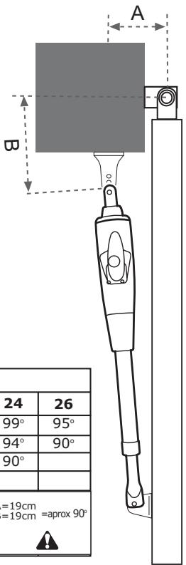
LYN300
| A | |||||||
| B | 10 | 12 | 14 | 16 | 18 | 20 22 | |
| 10 | 115° | 110° | 105° | 100° | |||
| 12 | 110° | 121° | 101° | 100° | 94° | ||
| 14 | 108° | 105° | 93° | 100° | 92° | ||
| 16 | 106° | 95° | 87° | 87° | |||
| 18 | 93° | A=15cm B=15cm =aprox 90° | |||||
| 20 | |||||||
| 22 | |||||||
LYN400