SLY250 - Garage Door Motor System CHAMBERLAIN - Free user manual and instructions
Find the device manual for free SLY250 CHAMBERLAIN in PDF.
User questions about SLY250 CHAMBERLAIN
0 question about this device. Answer the ones you know or ask your own.
Ask a new question about this device
Download the instructions for your Garage Door Motor System in PDF format for free! Find your manual SLY250 - CHAMBERLAIN and take your electronic device back in hand. On this page are published all the documents necessary for the use of your device. SLY250 by CHAMBERLAIN.
USER MANUAL SLY250 CHAMBERLAIN
AT/BA/BE/BG/CH/CY/CZ/DE/DK/ES/
FR/GB/GR/HR/HU/IE/IS/IT/LU/MT/NL/
NO/PL/PT/RO/RU/SE/SI/SK/TR/YU
1.2006/95/EC, 2004/108/EC, 1999/5/EG
Einschluβerklärung
Manager, Regulatory Affairs
Chamberlain GmbH
D-66793 Saarwellingen
July, 2008

Harry Naumann Dipl. ing.(FH) Manager, Regulatory Affairs
INSTRUCTIONS IMPORTANTES POUR LE MONTAGE ET L'UTILISATION
VEUILLEZ TOUT D'ABORD LIRE CES REGLES DE SECURITE IMPORTANTES

Manager, Regulatory Affairs
Chamberlain GmbH
D-66793 Saarwellingen
July, 2008

Harry Naumann Dipl. Ing.(FH)
Manager, Regulatory Affairs
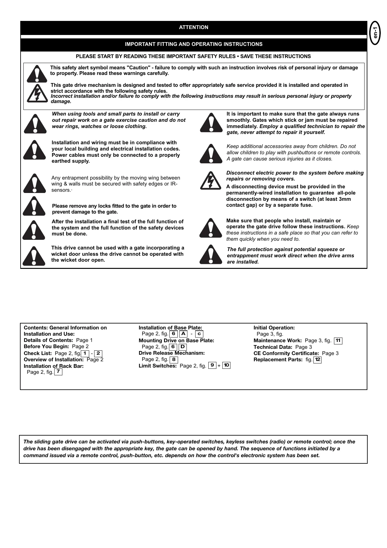
IMPORTANT FITTING AND OPERATING INSTRUCTIONS
PLEASE START BY READING THESE IMPORTANT SAFETY RULES • SAVE THESE INSTRUCTIONS


This safety alert symbol means "Caution" - failure to comply with such an instruction involves risk of personal injury or damage to property. Please read these warnings carefully.
This gate drive mechanism is designed and tested to offer appropriately safe service provided it is installed and operated in strict accordance with the following safety rules.
Incorrect installation and/or failure to comply with the following instructions may result in serious personal injury or property damage.

When using tools and small parts to install or carry out repair work on a gate exercise caution and do not wear rings, watches or loose clothing.

It is important to make sure that the gate always runs smoothly. Gates which stick or jam must be repaired immediately. Employ a qualified technician to repair the gate, never attempt to repair it yourself.

Installation and wiring must be in compliance with your local building and electrical installation codes. Power cables must only be connected to a properly earthed supply.

Keep additional accessories away from children. Do not allow children to play with pushbuttons or remote controls. A gate can cause serious injuries as it closes.

Any entrapment possibility by the moving wing between wing & walls must be secured with safety edges or IR-sensors.

Disconnect electric power to the system before making repairs or removing covers.

Please remove any locks fitted to the gate in order to prevent damage to the gate.
A disconnecting device must be provided in the permanently-wired installation to guarantee all-pole disconnection by means of a switch (at least 3mm contact gap) or by a separate fuse.

After the installation a final test of the full function of the system and the full function of the safety devices must be done.

Make sure that people who install, maintain or operate the gate drive follow these instructions. Keep these instructions in a safe place so that you can refer to them quickly when you need to.

This drive cannot be used with a gate incorporating a wicket door unless the drive cannot be operated with the wicket door open.

The full protection against potential squeeze or entrappment must work direct when the drive arms are installed.
Contents: General Information on Installation and Use:
Details of Contents: Page 1
Before You Begin: Page 2
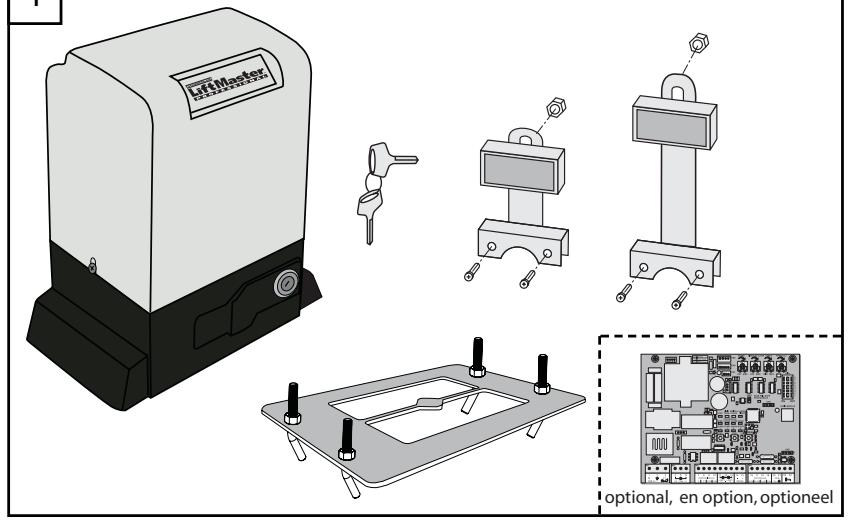
Check List: Page 2, fig.1 -2
Overview of Installation: Page 2
Installation of Rack Bar:
Page 2, fig.7
Installation of Base Plate:
Page 2, fig. 6 A - c
Mounting Drive on Base Plate:
Page 2, fig. 6
Drive Release Mechanism:
Page 2, fig. 8
Limit Switches: Page 2, fig. 9 + 10
Initial Operation:
Page 3, fig.
Maintenance Work: Page 3, fig. [11]
Technical Data: Page 3
CE Conformity Certificate: Page 3
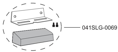
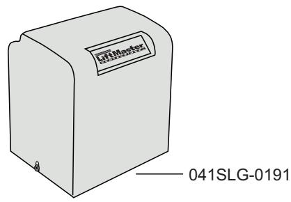
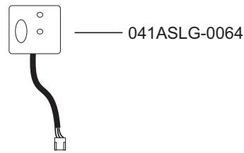
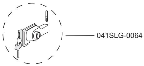
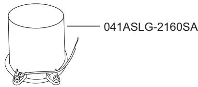
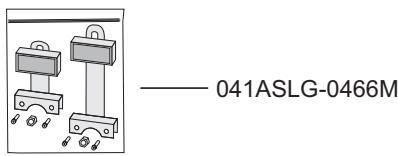
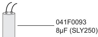
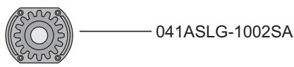
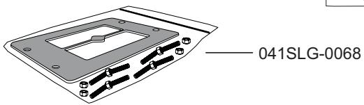
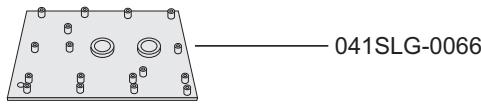
Replacement Parts: fig. 12
The sliding gate drive can be activated via push Buttons, key-operated switches, keyless switches (radio) or remote control; once the drive has been disengaged with the appropriate key, the gate can be opened by hand. The sequence of functions initiated by a command issued via a remote control, push-button, etc. depends on how the control's electronic system has been set.
BEFORE YOU BEGIN
There are many factors that are key to the choice of the right sliding gate drive. Assuming the gate is in good working order, the most difficult aspect is getting the gate to move. Once the gate is in motion, force requirements are in the main significantly reduced.
- Gate size: Gate size is a very important factor. A light yet long gate (long = +5m) needs a far greater force to set it in motion than a short, heavy gate does.
WIND CAN BRAKE A GATE'S MOVEMENT OR MAKE IT HARD TO MOVE, THUS INCREASING FORCE REQUIREMENTS SIGNIFICANTLY.
- Gate weight: Gate weight is only an approximate indicator the actual relevance of which can vary greatly. Example: A light gate that slides poorly is likely to need a stronger drive than a heavy, smooth-sliding gate.
- Temperature: Low outdoor temperatures make it difficult or, in some cases, impossible to get the gate moving due, for instance, to changes in the ground conditions. In such cases, a stronger drive again might be necessary. High outdoor temperatures can cause the thermal protection mechanism to be activated sooner.
- Operating frequency / Duty cycle: Sliding gate drives have a maximum duty cycle of approx. 30% (e.g. 30% per hour). CAUTION: The drives were not designed to be run for the maximum duty cycle on a regular basis (permanent operation). If the drive gets too hot, it switches itself off until it has cooled down to activation temperature. The outdoor temperature and the gate itself are key factors determining the drive's actual duty cycle
- Safety: A sliding gate drive has to be fitted with a flashing lamp, contact strips and, if necessary, with additional light barriers as safety features. Please ensure that you comply with the standards and regulations relevant to your particular case.
- Control unit: The control unit was developed specifically with safety aspects in mind.
CHECK LIST - PRE-INSTALLATION WORK 1 - 2
Prior to actual installation, please check that you have been provided with all the parts indicated within the scope of supply. [1]
Make sure your gate system is in good working order. The gate must run smoothly, not jerkily and not make contact with the ground at any point. Bear in mind that the ground can be several centimetres higher in winter. The gate needs to be stable with as little play as possible to prevent any lateral movement from occurring. The easier the gate moves, the more sensitive the force setting needs to be.
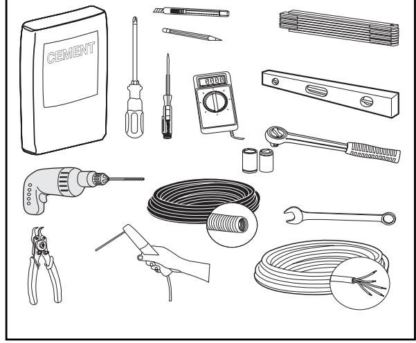
Make a note of the materials you still need and make sure you obtain them prior to installation - adhesive anchors (strong plugs), screws, stops, cable, distributor boxes, tools, etc. 2
OVERVIEW OF INSTALLATION 3 - 7 + 11
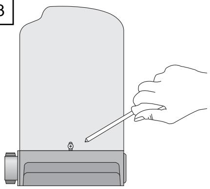
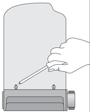
Open drive (fig.3)
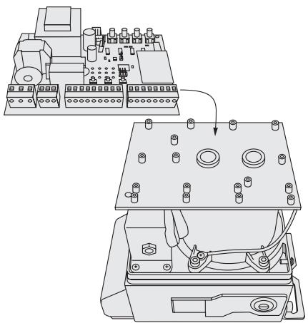
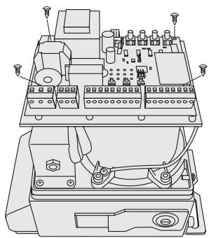
Install controlboard (fig.4)
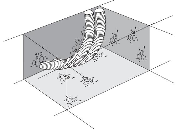
The drive has to be installed behind the wall to ensure that no part of it projects out into the gate opening. The motor has to be mounted on the flush fitted base plate. The rack bar shown has to be fitted to the gate with the fixing material supplied.
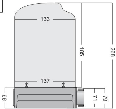
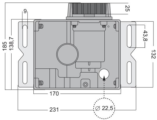
Decide which is the best height for fixing the rack bar to the gate and use this to determine the installation dimensions for the motor unit and base plate. Dimensions of the drive (fig.5). Should the gate be unsuitable for fitting the rack bar to it, a fixing profile (angle bracket, shaped tubing, etc.) needs to be mounted first.
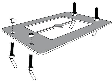
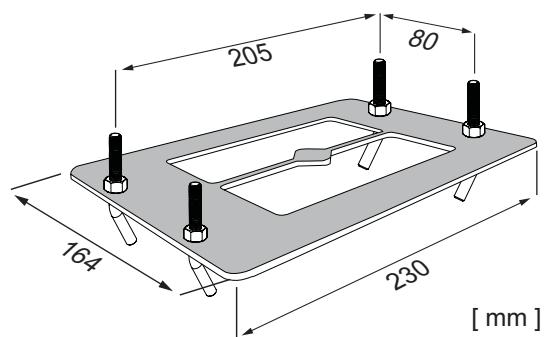
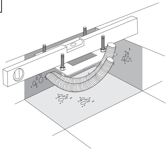
INSTALLATION OF DRIVE BASE PLATE 6 A - C
The base plate for the drive can either be concreted in or, if appropriate, welded into position. The place where the base plate is usually located is shown on the installation overview. The concrete plinth needs to be of an appropriate size (approx. 50cm× 50cm× 50cm ).
Please note: If it is impossible to precisely determine the height of the plinth and the distance from the gate prior to installation, it is advisable to mount the rack bars first and then concrete in the base plate. Spacers are fitted to move the rack bars approx. 40mm towards the inside.
The distance from the bottom edge of the rack bar to the base plate is approx. 8 cm. The base plate permits final height and depth adjustments of several centimetres to be made, but you are advised to work as precisely as possible from the outset.
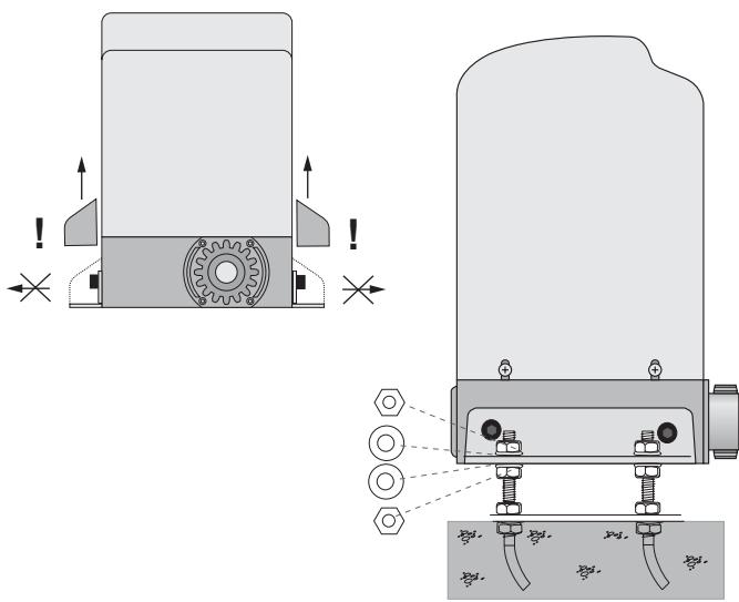
MOUNTING MOTOR AND GEAR UNIT 6 D
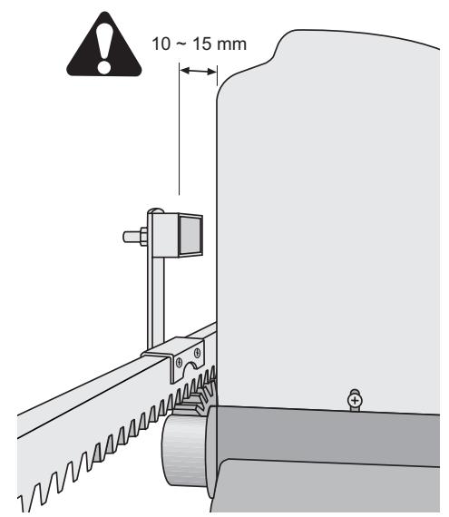
The drive should be fitted on to the threaded bolts in the base plate. The height should be set such that there is a gap of approx. 1 - 2mm between the cog wheel and the rack bar. The weight of the gate should not be borne by the cog wheel! Position the drive via the adjustment holes such that its location vis-à-vis the rack bar complies with the installation dimensions.
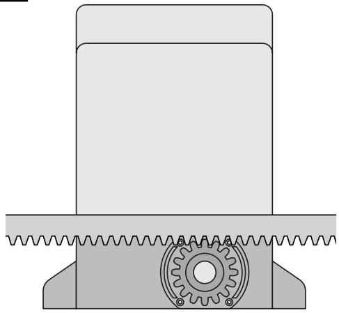
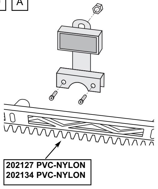
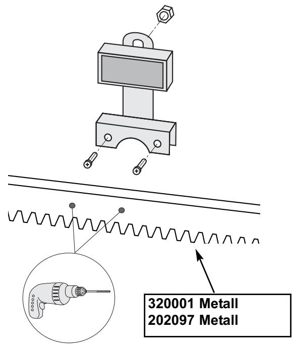
MOUNTING RACK BAR 7
The easiest way to fit the rack bar is to first place it on the motor's drive cog, disengage the motor and, by pushing the gate further with the rack bar, screwing the bar bit by bit firmly in position. In this way, you ensure that the rail bar engages with the cog wheel in an optimum manner. While doing this, do not forget to mark each fixing point.
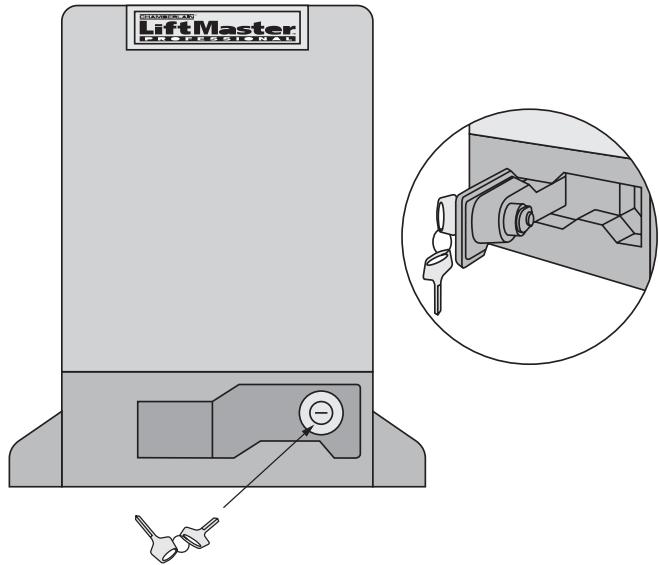
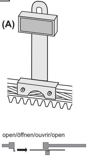
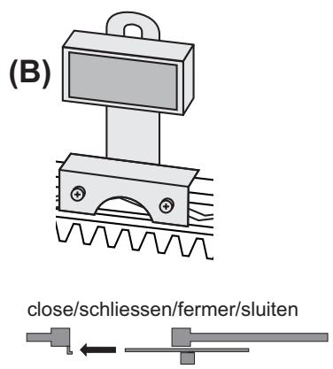
DRIVE RELEASE MECHANISM (MANUAL OPERATION) 8
The drive is equipped with a lockable release mechanism to enable the gate to be operated manually in a power cut. The release mechanism is shown in fig. 8 with the clutch disengaging the link between the cog wheel and the gear.
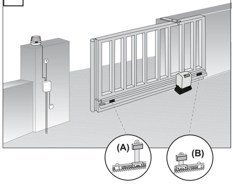
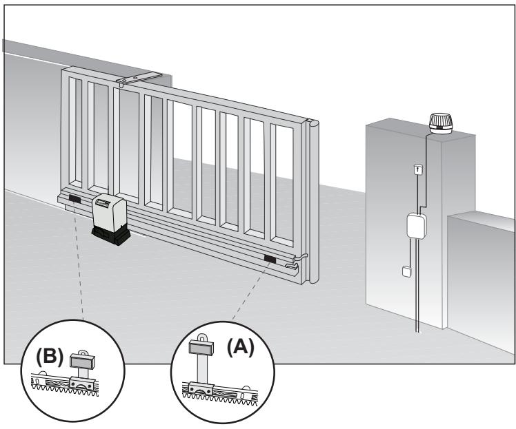
FITTING LIMIT SWITCHES (TO GATE) 9 + 10
The limit switches are assembled as shown in fig. 9A-C, 10.
Fit the limit switches on to the rack bar in those places where the final travel positions are roughly expected to be. The magnet should point towards the motor. The switch (contact) is located in the middle of the motor. Screw the retaining clip only provisionally in place or slot it lightly on to the rack bar.
Caution: Please notice fitting of the magnets on the rack bar (fig. 10)
Caution: A sliding gate must run in a guide rail and should not be able to leave the rail. This means end stops need to be fitted for both directions!
INITIAL OPERATION
Check gate functionality manually when the drive has been disengaged. Electrical operation is only possible with acontrol unit.
Electrical connections: See control unit instructions.
Always ensure that the mechanical and electrical safety requirements relevant to the given system are complied with.
MAINTENANCE WORK
The drive mechanics are maintenance-free. Check at regular intervals (monthly) that the gate hardware and the drive are all firmly in place. Disengage the drive and check gate functionality. Only an easy-running gate will work well with a drive. A drive is no substitute for a poorly functioning gate.
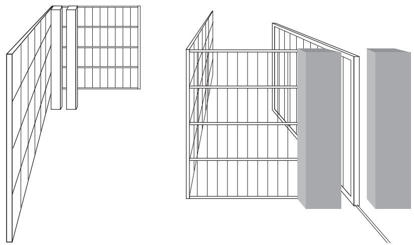
A sliding gate can also be secured by implementing on-site measures (fence, wall, etc.). See fig. 11.
TECHNICAL DATA
| Voltage IN | 230Volt |
| Frequency | 50Hz |
| Nominal Power | 120W |
| Max. Power | 130 |
| Current rated | 1A |
| Torque | 6Nm |
| Capacitor | 8μF |
| Motor Speed | 1380 |
| Working Temperatur | -25°C - +55°C |
| Range | |
| Protection Class | IP44 |
Declaration of Conformity
Automatic Gate Opener Models SLY250XXX are in conformity to the applicable sections of StandardsEN300220-3 · EN55014 · EN61000-3 · EN60555, EN60335-1 · ETS 300 683 · EN60335-1: 2002 · EN60335-2-103: 2003 · EN55014-1: 2000 + A1 + A2 · EN55014-2: 2001 · EN61000-3-2: 2000 · EN61000-3-3: 1995 + A1 · EN 301 489-3, V1.3.1 · EN 300 220-3 V1.1.1 · EN13241-1
per the provisions & all amendments of the EU Directives . . . . . . . . . . . . . . . . . . . . . . . . . . . . . . . . . . . . . . . . . . . . . . . . . . . . . . . . . . . . . . . . . . . . . . . . . . . . . . . .
2006/95/EC, 2004/108/EC, 1999/5/EG
Declaration of Incorporation
Automatic Gate Opener Models, when installed and maintained according to all the Manufacturer's instructions in combination with a Gate, which has also been installed and maintained according to all the Manufacturer's instructions, meets the provisions of EU Directive 98/38EC and all amendments.
I, the undersigned, hereby declare that the equipment specified above and any accessory listed in the manual conforms to the above Directives and Standards.
Harry Naumann
Manager, Regulatory Affairs
Chamberlain GmbH
D-66793 Saarwellinge
July, 2008


IMPORTANT ISTRUZIONI PER IL MONTAGGIO E L'USO
PER PRIMA COSA LEGGERE QUESTE IMPORTANTI NORME DI SICUREZZA!


Manager, Regulatory Affairs
Chamberlain GmbH
D-66793 Saarwellingen
July, 2008

Harry Naumann Dipl. Ing.(FH)
Manager, Regulatory Affairs
BELANGRIJKE INSTRUCTIES VOOR MONTAGE EN GEBRUIK
BEGIN MET HET LEZEN VAN DEZE BELANGRIJKE VEILIGHEIDSINSTRUCTIES!


The easiest way to fit the rack bar is to first place it on the motor's drive cog, disengage the motor and, by pushing the gate further with the rack bar, screwing the bar bit by bit firmly in position. In this way, you ensure that the rail bar engages with the cog wheel in an optimum manner. While doing this, do not forget to mark each fixing point.
AANDRIJVING ONTGRENDELEN (HANDBEDIENING) 8
Harry Naumann Dipl. ing.(FH) Manager, Regulatory Affairs
DULEZITE POKNY K MONTAZI A POUZITI
ZACNÉTE TÍM, ZE SI PRECTETE TATO DÜLEZITÁ BEZPEÇNOSTNÍ PRAVIDLA


Manager, Regulatory Affairs
Chamberlain GmbH
D-66793 Saarwellingen
July, 2008

Harry Naumann Dipl. Ing.(FH)
Manager, Regulatory Affairs
FONTOS TUDNIVALOK A SZERELESESHEZ E S A HASNZALATHOZ
KEZDJE EZEN FONTOS BIZTONSAGI SZABÁLYOK OLVASÁSÁVAL.
Manager, Regulatory Affairs
INSTRUÇÉS IMPORTANTES PARA A MONTAGEM E UTILIZAZão
COMECE POR LER ESTAS NORMAS DE SEGURANÇA IMPORTANTES


Manager, Regulatory Affairs
Chamberlain GmbH
D-66793 Saarwellingen
July, 2008


Harry Naumann Dipl.Ing.(FH)
Manager, Regulatory Affairs
WAZNE WSKAZOWKI DOTYCZE MONTAZI WYKORZYSTANIA
NA POCZATEK NALEZY ZAPOZNAĆ SIE Z NINIEJSZYMI WAZNYMI ZASADAMI BEZPIECZEÑSTWA

INFORMACJE POCZATKOWE
2006/95/EC, 2004/108/EC, 1999/5/WE
Manager, Regulatory Affairs
Chamberlain GmbH
D-66793 Saarwellingen
July, 2008


Harry Naumann Dipl. Ing.(FH)
Manager, Regulatory Affairs
BAXHbIe YKA3AHnI PO MOHTAXU IcNoJIb3OBAHnIO
HACHNTE C IPOUTEHIN 3TINX BAXKbIX IPIPABNJ TEXHNI K E3OJNACHOCTN


3Tn npEynpexkaioune cHMBOJI bO3HaayoT "BHHMaHne", oBaIeHne K BaIeMy BHHMaHIO, taK KaKnx Hec6bIHOeHne MorJIo 6bl npuHNHTBpeD 3dOpOBbIO yelOBeka IIIM MaTePnaIbHbI yIep6.
Ioxaynyucta, BHMaTeNbHO npOHTaTE 3TN npEynpeXeHn.
Данньй ппвор БОРТСКОНСТурOBAH И OTТСТИРОВАн ТAKIM OБразим,ЧTOбы ппс CBоЕ YCTAHOBKe И NCПОЛБОВAHи (пп рочHOM COБЛЮDEн Nправи.TEXHKN663ONaCHOCTN) ON ppeIOCTaBnJI 6bl NOЛьЗОВATEJIО OTHOCHTeNBHyO 6e3ONaCHOCTb.ИTOROM HECO6ЛЮDEн HAcTOrIux Nправи.TEXHKN663ONaCHOCTN MOKET 6blTb BpeI, ппчнEHьь 3dopoBBJлЮdeи nIN MaTePnaJBьн yuEp6.

Ipu MaHunyIaIcuaX c UHCmpymeHmAmu u MeKumU yacmMa deuecmeyume c ocmopoxhocmbu u He Hocume KOnbua (nepcmHu), yacbU c6o6oHyIO odexdy (ecNu Ha eopomax ocyuememrpaobmI no ux ycmaHOeke u peMoHmy).

3JektpoPoBOKy Heo6xOdMn POkJaIbIBaTb B COOTBeCTBm C MeCTHbIMN CTPOITeJIbHbIMN HOpMaMn INHCTpyKUmaM, OTHOCsAUMMCr K 3JekTpOPOBODKe. PIOkJIuOHeNe 3JekTpnuCeCKOrO Ka6eR N npaBnIbHO 3a3emJeHHo CeTn MoKeT OCyUeCTBnIbTb JInuB abTOPn3OBaHHb pa60THNK - 3JekTpNK.

Ipu MoHmaxe Heo6xOUMo npuHm8 6eHumHue onaChocmb 3axamur MExdy nepemueaemou yacmbEOopom u Okpykaoumu yacmru 3daHn, Hapumep: cmHo.

ДлгTOrO,чTO6bI BOCnpeNЯТСТВОВaTБ BO3HnKHOBEHnIO NOBpeJdeHnI,пОжaJIyuCTa,уДaJIte I3 BOPOT BCE BMOHTnPOBaHHbE B HIX 3aMKn.

Iocne yctaHOBKn Heo6xOJIMO npOBepntb MexaHn3Ma Ha npaBnIbHOCTb erO HacTPOIKN, a TaKKe npNBOD, cnCTeMbI 6e30NaChOCTn n aBapNIHoro OT6IOKInpOBAHnHa IpeDMeTnx npaBnIbHOrO fYHKUHOHnPOBaHn.

EcIn B BOPoTax yCTaHOBJIeHbI DBePn IJy npoxOa,TO npINBOHNO MExAHN3M HeJIb3A3nyCTNTb ININ OCTaBNTb erO BKIIIOUeHHbIM Do Tex nop, NOKA BOPoTA He 6yDyt DOJIKHBIM O6pa3OM 3aKpbITbl.

Baxho, yTo6bI nepeMeueHne BOpT 6blIO 6blIO noCToHHO rnaKIM. BOpTa, KOToBle 3aknHraTc nn 6byT 3aeDaTb, Heo6xOIMO HeMeIeHNO OTPeMOHTnpOBaTb. He np6yIte peMOHTnpOBaTb BOpT caM. ObpaNTecb 3a NOMOu b K cneuaNtcty.

Донон'teьн'te yctpoCTBa pa3mecTne TaK,чTOБы OHI He 6bIи DoCTynHbI DeTAM. He no3BOJnTe DeTAM,чTOБы OHI MaHInyIpOBaJI N C KHOtKamN I nDuctaHcNoHHbIM UypaBHeHem. 3akpbIbaIOUncEca BOPota MOrY npuHnHbT b TReKeIbe paHeHn.
Ipu ocyuemeenu pa6om no yxody, Hapumep: npu ouucmke, aemomamueecku ynpaenembte ycmpoucmea donxhbl 6bimb omknnoehbl u3 cemu 3nekmponumanu.
YJxctKO NOdkJIIOUeHHo 3JeKTPoIPoBOJDN HeO6XODMO NOMHnTb 06 yCTPOIcTBe pa3MbIKaHNy dIraTO, YTO6bI BO BcEx NOnJx OTKIIIOeHHN 6blIO 6blI rapaHTnpOBaHO OTKIOUeHne npi NOMOuIN nepeKIOUaTeJIa (pa3MbIKaHNe KOHTaKTOB He MeHee 3 MM) nI IN pN NOMOUI ONDeIbHorO ppeOxApanTeJI.

Obecnebyte, YTO6bI Te INaCa, KOToPbIe OcyuIeCTBnIOT MOHTaK, yXoD I OcbnyKINBaHne npNBOa, co6blOdaII Tpe6OBaHHaHCTOJIe HNcTpyKUn. IVHcmpyKUIO pa3MeCmume B makOM MeCme, 2de 6bI OHa 6blNa 6bICmpo docmynHa.

Iocne MoHmka npuBoda doJnKha 6bImb 6e3ycNoHo oEscneueHa oxpHa Mecm, e Komopbix cyuecmeyem yap03a 6o3HuKnHOeHua yuu6oE u nope3o8.
CoepeKHaHHe:O6uHne yKa3aHnno MoHTaKy n 3KcPJIyatauHn:
OrnaBJIeHne: cTp.1
Ipexe, yem Haayatb: ctp.2
KoHTpOJIbHbI cINcOK: cTp.2,pnc.1 - 2
063op MoHTaxKa: cTp.2
MOnTaX 3y6aToN peKn: cTp.2,pnc
MONTAX NNITbI OCHOBAHNA:
CTp.2 6 A C
MOnTaux pnpB0da Ha nIInTe oChOBaHnA:
ctp.2,pwc.6 D
ДeблOKированe: cтp. 2, рс. 8
Kohehble BbIKJIOuTeN:
CTP. 2, PNC. [9] + [10]
IepBoe BkJIOueHne:
CTP.3,pnc.
Texo6cnyxmbaHne: ctp.3,pnc.11
exHnueckne xapaKTepeuCTnKn: cTp.3
CepTHΦHKAT COOTBETCTBnH HOpMaM EC: cTp.3
3anactn: pnc. 12
PnBOD pa3DbNkHbIX BOpOT MoKET 6bITb BKIOUeH C NOMOJIbKO KHONOHOR BbIKIOUaTeJI, 3AMKOBORo BbIKIOUaTeJI, INJI JxBeCKHOIOHOr BO bIKIOUaTeJI (paINOBbIKIOUaTeJI) n OncpeIDCTBOM DCtAHUNOHOR ynpabLeHn: NocIe OTCOEINHEHn PpIBOda C NOMOJIbO npINaRaEMOR KIOUa BOPota MOryT 6bITb OKpbItb BYpHuYIO. BblONHeHne FyHKcI npB KIOUeHm DaTuHa KOMAn (DInCTaHUNOHoe YnpabLeHn, KHOIOUHb BbIKIOUaTeJI n T.D.) 3abNCHT OT UCTaHOBOK 3NEKTPOHNIu YnpabNeHn.
PpeKde, yem HaaytB
IpaBnHbI Bb6op npB0da BOPOT 3aBcNt OT MHOrn X paKTopoB. C ToUKN 3peHn IcnpaBHorO cyHKUHOHPOBaHn HauBoJe cNoXhIM N3 HNX ABJIeTcra "BbE3d" BOPOT. KorDa BOpota nepemuaOTc,ДЯ 3TOr Tpe6yETc cyueCTBeHNO Mehlaa Cnla.
- Pa3mep BOpOr: Pa3mep BOpO rAblnreTc OChb BaXhblmФakTopom. JIeKne n, B TO JKe BpeMra, DInHHbIe BOpota (DInHa=+5M)ДЯnpBVeDEHnN INB DBNXeHne Tpe6yIOT 3NaHTeJIbHO BoJbWe CINbI TgN, Yem KopoTKne, HO 6OJIee TAgKeJIbE BOpota. BETEP MOKET TOPMO3NTb BOPOTA INJN CO3DABATb HINX MEXAHnueCKNe HANPAXEHN, B PE3YJbTATE YERO TPEBYEMAR CNIA TAFN CYUCTBEHNO BO3PACTAET.
- Macca BOPOT:Уka3aHHoe 3HaueHHe MACcBi BOPOT YBnAETCJI NIIb IIpIMePHoB EJIInuHoiK, KOTOpA MoKet 3aMeTHO OTINuABycHOT pAKTNUeCKNX Tpe6BaHNI. HanpImep,ДЯлERKnx BOPOT C PINOxM KaueHem Tpe6yEtCnHorda 60lbshn IprNBoD, yEM B Cnyae TJeXeIbIX BOPOT, OblaDaIOUxN IerKm XODOM.
TemnepaTypa: Hn3Kne HapyKnIe TemnepaTpybl MoryT 3aTpUdHnTb BbIe3D BOpOT (N3MeHeHn YpOBH nOuBbl nIp.) NII BOCnPENrTCTBOBaT bmy. BNoIO6HbIX cNyAyx Heo6XoDMo npEdyCMOTpeTB 60nee MoUhbl pINBOID. BbICOKne HapyKnIe TemnepaTpybl MOrY TnpBOIDt K IpEJDeBpeMeHHOMy Cpa6aTbIBaHNIO TepMO3aUNtbl.
Pa6o7a Yactota/Bpem BKJIoueHn: PnpBoDbl pa3DbNkHbIX BOPOT IMeOT MaKcImaIbHoE Bpem BKJIOueHn, paBHOe npimepHO 30% ot HopMbI (Haipimep, 30% ot Yaca). BHIMAHNE! PnpBObl He pacHTaHbI Ha npOdoJIxKteNbHyOp pa6To npi MaKcImaIbHom BpeMeHN BKJIIOueHn (NoCToHHaN EKcIpyatau). Korda npBOD nepePBeBaETcH, OH OTKJIIOueAETcN BKJIIOUaeTc CHOba ToIbKO pRn CnHexeHN TMnepaTpbl Do yCTaHOBLeHHoro 3NaueHn BKJIIOueHn. HApXHa TEmpepatypa N TIN BOPOr ABIIIOCTcBAxKbIMn NapameTpamn dJa fakTtueckOro BpeMeHN BKJIIOueHn. - Texnka 6e30anachoctn: Ппвод ра3дВньхьх Ворот сеДует obopydobatсpeДCTbAMn Textнки 6e30anachoctn TaKIMN, КAK MnaIauaЯ lamma, KOHTaKTHbIe pa3bEmbl N, NO Heo6xOДmocTn, ДОЛHNTeIbHbIM CBETOBbIM 3aTbOPOM. B IIObOM clyae co6JIoudaite COOTBETCTByUOuNE CTaHapTbI n PpeDIncaHnA.
CnCTema ynpaBHeHnpa3pa6aTbIbIacb CneuJIbHO c yUeTOM Tpe6oBaHn6eOJACHO 3KcNlyatauIN.
KOHTOJIbHbI CNICOK MOHTAXA - IOIIGOTOBITEJbHbIE OIIPEAUIN 1 - 2
Ipeep MoHTaXOM npOKOHpONpy Te yNAKOBky NocTaBKn Ha npEmdET KOMNJIeKTHOCTn.1
Y6eIntecb B 6e3ynpeHOM DeiCTBn Baunx BOpOT. BOpota DOJXhbl IMetb paBHomepHbI XoD 6e3 TOnjKOB n He DoJXhbl 3aBnCaTb HN B ODNOM MeCTe. POMHtE, YTO NOyBa 3ImHee BPeMa MoXeT BCnyuBaTcRa Ha NcKOJIbKO CaHTmEtpoB. IJrTO, YTo6bl N36ExKaTb MaTHNKOBbIX NepMeUeHn, BOpTa DoJXhbl ObnJaTa b yCTOUnBOCTbIO n He n MeTb 3a3OpOB. Yem JIeue DInXKeHne KpbJNa BOPOT, TEM TOHHe DOnJXHa 6bITb HAcTpoKa Cnbl Tarn. 3aII nIte, KaKne eUe Tpe6yIOTc MaTePnaJIb. I ObecneYbTe IN HAJIyNe K NaAany MOHTaxa, HAnpIMep: CAMOKJeOUnceA hKepebl (npOchIbe IIO6eI), BNHTbl, OrpaHUNTEIeXoJa, Ka6eIIN, paCnpdeJIInTeJIbHbIe KOpO6Kn, IHCTpyMeHtBi I T.D. 2
OE30P MOHTAXA 3-7+11
BAXHbIE YKA3AHNIA NO TEXHNKE 6E3ONACHOCTNI PPNMOHTAXE.BHIMAHHE! HENPABUNbHbI MOHTAX MOKETIPNBECTN K CEPbE3HbIM TPABMAM!
OTkpbltb3YbHTAOI PEIKN (pncynke 3)
MOHTAXOM CNTeMa ynpabJeHnra (pucyHke 4)
BHMaHHe! O6paaMaTe BHMaHHe Ha MOHTaX MaHHTOB Ha 3y6CuToi peKe (10).
BHMaHHe:Pa3dBnXHbIe BOPoTa DoJHXbI nepeMeaTbcraB B bHyKdEHHom pexHMe, t.e. He MoKeTe 6bITb TaK, YTO6bI BOPoTa CXOJIIN C HAnpaBnAIOxN. PpN DnIXKeHN BOPOT B OboNX HApBaJIeHnx DoJHXbI 6bITb npedycMOTpeHbOrpaHnHTeTI XOJa.
NEPBOE BKJIIOUeyHne
Поберп Te Фуннюнорова Н БОТ Вучну пи ДеблOKИРОВАНСоСТOrHIM ПИВОДа. 3ЛЕКТчecкoe ВКЛЮЧЕНЕ АВЛЯETC RABOМЖьIM TOЛБКО C NOMOцьО 6ЛOKa Управелен ИЗ KOMЛЯЕТА NOCTaBК.
Cneinte Bcerda 3a Tem, YTO6bI dIy yCTpoiCTBa BblONHJIINCb COOTBeTCTByIOUIIne IpeDIIncAHN NO oBecNeueHIO 6e3ONaCHO 3KcPnyatauIM MekaHnueCKO IN 3JekTpnuEeCKO YAcTNI.
TEXO6CJIYXKINBAHNE
Mexahnka npnboda He Tpe6yet 0cbnykBaHn. Ype3 perynpHbIe INTEPBAblbBpeMeHn (Kakdb MeCz) npOBepaTe HacNlaKy BOPOT N MOTOPaHa NpEaMeT PPOuHocTn KpeNexa. De6NOKpyuTe npNbOD n pOBepbTe FyHKcUHOHPOBaHne BOPOT. C npNbODom XopoO MoYr FyHKcUHOHPOBaTb ToJbKO BOPoTa, OblaDaIOuJe IeRKM XoDM. PtNBdNe He MOxET cKomnEHCpOBaTb PINOxoe FyHKcUHOHPOBaHne BOPOT.
Pa3dBnKhIe BOpTa MOryT 6bIT TaXKe 3aunIeHbI 3a Cuet CTponTeJbHbIX MeOpnpAtni (3a6Op, cTeHa). Cm. pnc. 11.
TEXHINCHECKNE XAPAKTEPNUCTNIK
HapnxHe nTaHn 230 BoJbT
Yactota 50 T
MoUHOCb 120BT
MoUHocTb max. 130 Bt
IopTe6JIReMbI TOK 1A
KpyTAAH MOMENT 6HM
KoHdEHCatOp 8uF
Uncno o6oPoToB MoToPa 1380rpm
Paoboua TemnepaTypa 0T-25Cdo+55C
Klacc 3aunTbI IP44
3aBHeHne O COOTBeTCTBHN
ABTomatHueckne npBovbI BOpO t cepn moDeene SLY250XXXyDObNETBopHOT
Tpe6oBAHnM DeiCTBvIOuNX
pa3dienbO CTanIapOB EN3002220-3,EN55014,EN61000,EN61000-3,EN60555, EN6055-4,ETN200-3,EN6090-3,EN6090-1,EN6100-1,EN6100-2
EN60335-1, ETS 300 683, EN60335-1:2002, EN60335-2-103:2003, EN55014-1:
2000+A1+A2, EN55014-2:2:2001, EN61000-3-2:2000, EN61000-3-3:1995+A1, EN 2001-1001-2002-2003-1995-1006-1997-1008-1
301 489-3. V1.3.1, EN 300 220-3 V1.1.1, EN 13241-1,
a TaKke onpeJeHn i npynx dOnonHeHn dIpeKTNB EC. 2006/95/EC,
2004/108/EC, 1999/5/EG
3aBJIeHne O BKNIOUeyHn
ABTOMATHECKNE PBNDBI BOPOT YOBDBETBPOHOT ONOpEDENEHNIAM DIPeKTEMBI EC 98/38/EC N e eeONNHeHNI PN yCIOBNI, ECNI 3TN PNBOBdy cYCTaHOBNEHbI N oC6LNYBAIOCT C CO6LIHOENEM H NCTPCKYN I3N0TTOBNTENc I MNCN5BYOTC C BOPOTAMI, KOTObIe TaKxE YCTaHOBNeHbI N O6LCyKNAOITCA B COOTBETCTBN C n HCTPKUJIEN I3RTOBTENJIe.
HactoIIM HIXeNoDnucBmC3aBnAET,TO BbIeynomAHyTOe yCTPOICTBO,a
TaKxe BCE npuBeHeHHbIe B pyKOBoIDCTBE npHaIeXHOCTN, COOTBETCTBYOT
BbIWeHa3BaHHbIM DnpeKtTbAm I CTaHapTaM.
Harry Naumann
Manager, Regulatory Affairs
Chamberlain GmbH
D-66793 Saarwellingen
July, 2008

Harry Naumann Dipl. Ing. (FH)
Manager, Regulatory Affairs
1
2
3
4
5
[mm]
6
A
B
C
D
7
8
9
A
B
C
10
11
12 | REPLACEMENT PARTS
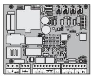
CB22
NOTES: