BAS300K - Garage Door Motor System CHAMBERLAIN - Free user manual and instructions
Find the device manual for free BAS300K CHAMBERLAIN in PDF.
User questions about BAS300K CHAMBERLAIN
0 question about this device. Answer the ones you know or ask your own.
Ask a new question about this device
Download the instructions for your Garage Door Motor System in PDF format for free! Find your manual BAS300K - CHAMBERLAIN and take your electronic device back in hand. On this page are published all the documents necessary for the use of your device. BAS300K by CHAMBERLAIN.
USER MANUAL BAS300K CHAMBERLAIN
ELEKTROSCHLOSS (OPTIONAL)
√89/336/EEC
73/23/EEC
1999/5/EC
Herstellererklarung
Manager, Regulatory Affairs
THE CHAMBERLAIN GROUP, INC.
Elmhurst, IL 60126
USA
May, 2004

Babana P. Keckhoh
Barbara P. Kelkhoff
Manager, Reg. Affairs
INSTRUCTIONS IMPORTANTES POUR LE MONTAGE ET L'UTILISATION
COMMENCEZ PAR LIRE CES IMPORTANTES CONSIGNES DE SECURITE

ACCESSORIES OPTIONNELS
Tension : 12/24 volts CA/CC
BARRE PALPEUSE (OPTION)
ARRET D'URGENCE (OPTION)
Manager, Regulatory Affairs
THE CHAMBERLAIN GROUP, INC.
Elmhurst, IL 60126
USA
May, 2004

Babana P. Keckhoh
Barbara P. Kelkhoff
anager, Reg. Affairs
IMPORT INFORMATION REGARDING INSTALLATION AND USAGE
PLEASE START BY READING THESE IMPORTANT SAFETY RULES • SAVE THESE INSTRUCTIONS


This safety alert symbol means "Caution" - failure to comply with such an instruction involves risk of personal injury or damage to property. Please read these warnings carefully.
This garage door opener is designed and tested to offer reasonable safe service provided it is installed, operated, maintained and tested in strict accordance with the instructions contained in this manual.

WARNING - INCORRECT INSTALLATION CAN LEAD TO SEVERE INJURY. FOLLOW ALL INSTALLATION INSTRUCTIONS.
Door must not extend over public footpaths or roads during operation.
Before installing the drive unit all ropes or chains, which are not required, must be removed and all devices, which are not required after the installation of the drive, must be put out of operation.
Install only on a properly balanced garage door in good operating condition. Sticking or binding doors must be repaired. Garage doors and components attached to them are under extreme tension. Do not attempt to repair or adjust them. Do not use if repair or adjustment work needs to be carried out as a defect in the system or an incorrectly balanced door can cause injuries. Get professional garage door service


The actuating member of a biased-off switch, if installed, is to be located within direct sight of the gate but away from moving parts. Unless it is key operated, it is to be installed at a minimum height of 1,5m and not accessible to the public. In accordance with the wiring regulations applying at the time, wired electrical installations must be equipped at each pole with an isolating device that has a contact opening measuring at least 3 mm.


This unit should not be installed in a damp or wet space.
Once the drive has been installed, measurements must be carried out in accordance with section 20 of EN60335-2-95:2001. If the levels measured exceed the maximum ones, a contact unit has to be used.


After installation and adjustment, ensure that your garage door reverses on contact with a 50mm high object placed on the floor. Repeat monthly and adjust as necessary.
WARNING - IT IS VITAL FOR THE SAFETY OF PERSONS TO FOLLOW ALL INSTRUCTIONS. SAVE THESE INSTRUCTIONS!

Watch the moving door and keep people away until it is completely opened or closed. Do not allow children to play with door controls. Keep remote controls away from children. Do not let children play with remote controls.

Set up permanent warning notices concerning the danger of the entrapment of body parts at conspicuous sites or close to fixed control or regulation equipment.
Permanently fix the sign for the manual release device close to its respective actuating element.
Use caution when operating manual release if the door is open, since it may fall rapidly if out of balance or if springs are weak or broken. Property damage or serious personal injury could result.
Disconnect electric power to the garage door opener before making repairs or removing covers.

This product is provided with a power supply cord of special design. If damaged, it must be replaced by a cord of the same type obtained from your local Chamberlain distributor, and must be fitted by a specialist.

After installation it is important to ensure that the drive unit prevents the opening movement – or stops – if the door is loaded with a weight of 20kg in the middle of the lower edge of the door (for drives which can be installed with a door which has openings in the door wing with a diameter greater than 50~mm ). EN 60335-2-95. Subclause 7.12.1.
| CONTENT | PAGE | FIGURES |
| Safety rules | 1 | |
| Content of the carton | 1 | |
| Before you begin & Installation | 1-2 | 1-3 |
| Installing the motor | 2-3 | 1-14 |
| Electrical installation, Safety | 4-6 | 5-8 + 15-24 |
| Control | 7 | |
| Maintenance | 7 | |
| Technical data | 7 | |
| Replacement parts | 11 | 25 |
CONTENT OF THE CARTON - FIG. 1
- Motor
- Release key
- Hardwarebag
- Manual
Electronic control
Infrared Sensor 1x
Transmitter
SUITABLE DOOR TYPES - FIG. 3
A - Up-and-over doors with vertical running rails
B - Non swing-out doors with vertical and horizontal running rails
C - Folding door (up-and-over door with folding leaves)
Doors up to 8m^2 can be operated with one drive
Doors from 8 to 14m^2 must be fitted with 2 drives
ADDITIONAL ESSENTIAL OR OPTIONAL ACCESSORIES
A Essential: (Fig.2):
BAS-1 Door strengthening rails: The use of a door strengthening frame is necessary for thin-walled doors. The drive housing can only be secured using these rails.
BAS-2 Revolving rods: Models available for doors up to 3 or 4m . Larger doors must be fitted with 2 drives (L + R)
BAS-3 Straight door arm = standard arm: The drive can be mounted so that the door guiding arm is not in the way. The arm is fixed at the side in the extension of the standard arm or it can be fixed on the inside of the door frame.
BAS-4 Curved door arm: The curved arm must be used if the straight arm would collide with the door guiding arm. Mostly with doors with little space at the side. The curved arm is then usually fixed on the inside of the door frame.
- Connecting cable suitable for 230 Volt (Type: 3x1.5VV, RR or RN-F
- Connecting cable for accessories (Type: VV or higher value)
- Cable strain relief
- At least 2 distribution boxes
- Flexible cable conduit (armoured conduit)
B Optional: (Fig. 4):
771E Additional photocells
- 60008 Upright stand for photocells
- 600046 + BAS-6 Safety Edge
100010, 100027 Key-operated switch
- 9747E Radio coded lock (keyless entry system)
- 600084 Emergency stop switch
Coiled cable
16200LM Door in door switch
203285 Electrical lock
- 75LM Wall pushbutton
- FLA230-2 Flashing lamp
INSTALLATION -
1
BEFORE YOU BEGIN
On the grounds of safety and to guarantee the perfect operation of the drive, the following points must be observed:
- The door must be suitable for automation. It must be particularly ensured that the door dimensions correspond with the technical properties in the specifications and that the door is suitably stable.
- Test the function capability of the door bearing and joining points.
- Ensure that the door does not have any wearing points. Clean running rails as necessary and lubricate them with silicone lubricant (not grease).
- Ensure that the door is correctly balanced.
- Remove the mechanical door locks in order to use the mechanical door locking system.
- A good earth connection must be available for connecting the drive.
The BAS drive can be installed in counterbalanced up-and-over doors of different designs. Some models are shown in Fig. 3:
a) Up-and-over door with single leaf.
b) Up-and-over door with folding leaf.
c) Up-and-over door with single leaf and ceiling running rails.
Do you have an access door in addition to the garage door? If not, the Outside Quick Release Accessory is required. This accessory allows manual operation of the garage door from outside in case of power failure.
SUMMARY OF COMPLETE ELECTRICAL INSTALLATION
Connection of electronic control PCB
For any sort of work on the electronic control PCB (connecting, programming, maintenance etc.), the power supply must always be disconnected.
The points in the GENERAL SAFETY REGULATIONS must be observed.
Prepare the cable channels and carry out the electrical connection of the controller to the respective accessories. Always disconnect the power cable from the control and safety cables (pushbuttons, receivers, photocells etc.). To avoid electrical faults separate jackets should be used. Then program the electronic controller as necessary according to the respective instructions.
The summary provides a general overview of the type of electrical wiring. It may be the case that other routes have to be selected. The drawings merely show the normal routes (Fig. 5-8).
A. Standard installation
B. Full installation
C. Full installation with 2 motors
D. External controller mounted on the wall
CONNECTION OF ONE DRIVE
The motor is an a.c. motor operated by a capacitor which requires a special controller. The turning direction is determined by changing the polarity of the cables L-L on the controller. N is the PEN conductor (blue).
Cable cross-section: 0.75mm^2 or greater.
Voltage: 230 V AC
Do not use rigid copper wires. Do not lay low voltage cables in parallel.
CONNECTION OF TWO DRIVES
When connecting up two motors the procedure is the same in principle. The second motor does not have a limit switch and also has no controller. It is operated as the "twin" of the first motor and is wired into the controller like the first motor.
Cable cross-section: 0.75mm^2 or greater.
Voltage: 230 V AC
Do not use rigid copper wires. Do not lay low voltage cables in parallel.
INSTALLATION OF DOOR STRENGTHENING RAILS (OPTIONAL)
Door strengthening rails are to be used for thin-walled doors or doors which are not torsionally stiff.
The drive unit is heavy and a safe stable fixing is essential. The rails available as accessories can also be adjusted in height and permit simple fixing of the drive cover. Two strengthening rails are necessary if two drives are used on one door.
The door strengthening rails are normally fitted to the top of the door frame and attached to a bracing beam on the door at the lower end. The strengthening rails must be attached to the frame so that they are very stable.
It is not technically important whether the drive is seated in the middle of the door or not. It is normally fitted away from the middle of the door if the door handle or lock are in the way and are not to be removed. The drive reduces the height in the garage by about 10cm . In low garages an off-centre position is used so that higher vehicles can still be driven into the garage. Because of this longer revolving rods may be required at one side.
INSTALLATION OF THE DRIVE ON THE DOOR
The drive can be mounted on the door strengthening rails at the most varied heights.
You should observe the following points as early as possible:
- The revolving rods, which are to be mounted later and which are attached with a guide bearing to the door frame or in its vicinity, also require a stable mounting position. A stiffening beam on the door would be suitable for this.
- In the case of a single-rail (vertical) up-and-over door, the height of the revolving rods for the drive system should be – as in a typical installation - approx. 10cm below the end of the joint on which the door swivels or from which it is suspended (see Fig. 12a+b). In the case of an up-and-over door with folding leaf the fulcrum point is approx. 10cm below the point at which it is folded. For a non swing-out double rail door the height of the door is halved.
- The height of the revolving rods also depends on the general height of the door. The telescopic door arm, which is to be fixed at the side later, may only be pulled out to a maximum of 80% of its reach (max. length 120~cm ). It is necessary to shorten the telescopic arm for small doors (see Fig. 12).
MOUNTING OF REVOLVING RODS (OPTIONAL)
The bearing (sheet metal angle) in which the revolving rods to the side of the door are guided, must be fixed extremely rigidly and must be lubricated with grease later after the installation has been completed. On the drive side the revolving rods are fitted with sleeves and are only pushed onto the drive. A small screw with an internal hex head in the sleeve secures the rod from slipping out.
It is strongly recommended that the side arms are first fixed before the revolving rods are cut to the required dimension.
INSTALLATION OF THE TELESCOPIC DOOR ARMS (OPTIONAL)
Whether the bent or straight telescopic door drive arms are used depends on the amount of space available at the side (Fig. 9). Where the drive arm is attached to the frame depends on the door type and the amount of mounting space available. As close as possible to the point at which the door turns (swings) is ideal. This attachment should be welded to be as stable as possible since high forces are transferred to it.
- Straight telescopic arms operate alongside the door arms which turn the door (the arm which turns the door does not cross the path of the telescopic drive arm). There is sufficient space on the door frame to fix the drive arms to the side, top or bottom.
- Bent telescopic arms are fitted over the door arms which turn the door and are attached if insufficient space is available at the side to avoid contact.
Both types of telescopic arm may only be pulled out to 80% of their full path (max. length 120~cm ). In the case of small doors it may be necessary to shorten the telescopic arms.
The telescopic arms must be lubricated before assembly so that they function smoothly.
Once the side telescopic arms are mounted the exact length of the revolving rods can be established. On the telescopic arms are sleeves which are pushed into the revolving rods. If desired this connection can be secured by drilling through and using 10mm pins or a welded connection is also possible. The last option is by far the most secure connection.
ADJUSTMENT OF THE BALANCE OF THE DOOR
Following mechanical installation it is necessary to check whether the up-and-over door is still in equilibrium after increasing the weight of the drive and the accessories. If necessary counterweights or torsion springs should be used to regain equilibrium. Optimum swivelling is guaranteed if the door remains in the medium position (45^) and is in equilibrium with the drive unlatched. Furthermore it should be ensured, by manually moving the door, that when opening and closing it the swing takes place linearly and without any jumps or abrupt movements.
LIMIT SWITCH ADJUSTMENT (BAS300K ONLY)
The limit switches are located to the right of the drive beneath a black plastic cover. By removing the 4 screws (Phillips, PZ1) the cover can be removed. The limit switches are triggered by 2 cans which can be adjusted on the shaft with a little force or by a screwdriver. The limit switch position determines the points "DOOR OPEN" and "DOOR CLOSED".
By turning the cam's switch-off point can be adjusted in both directions.
Setting for single motor operation (drive mounted centrally):
The outside limit switch is the one for DOOR OPEN.
The inner limit switch on the motor is DOOR CLOSED.
Setting for double motor operation (drives to the right and left):
If the drive is mounted with the limit switch RIGHT the adjustment is made as described above.
INSTALLATION OF DRIVE COVER
The drive cover is fixed at the side with 4 screws. Before positioning the drive cover the plastic thread inserts must be pushed into the door strengthening rails at the appropriate height. Before the cover is pushed on from the front, the screws should be given another turn.
EXCHANGING BULBS
Warning: Isolate drive from mains.
The plastic cover is screwed on at the side and after removing 2 screws on the left and 2 on the right it can be pulled downwards.
The transparent light cover underneath is fixed with 4 Phillips screws (PZ1) and after they have been removed it can be lifted off. The bulb is seated in a screw holder, type E14/25W.
Never use stronger bulbs. After exchanging the bulb reassembly takes place in the reverse order. Pay attention to the sealing fitting around the transparent light cover, which must be properly positioned.
Bulbs are not subject to guarantee claims.
LATCH / UNLATCH DRIVE
If the drive is unlatched the door can be opened or closed by hand.
If the drive is locked the door can only be operated with the drive.
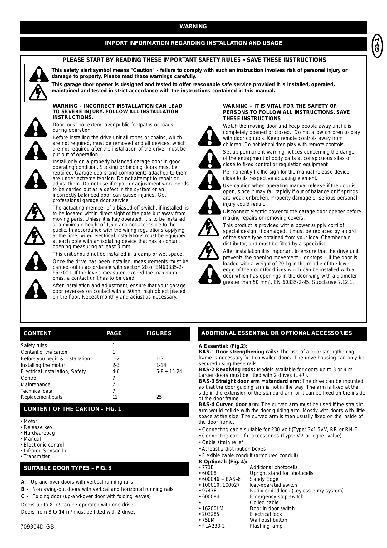
Unlatching:
In a recess at the back of the plastic cover is an unlatching key. Take it out and push it into the marked opening which is also on the back of the drive. By turning it clockwise through about 180^ the drive is unlatched.
Latching:
With the unlatching key pushed in turn it clockwise until you feel a solid resistance. Then move the door a little by hand until you hear it click or you can establish that the door is latched again.
If 2 drives are mounted on the door both of them must be unlatched and latched.
If the garage has no external access it is necessary to mount an external unlatching system for the situation when the drive is without power.
Functionality of the emergency unlatching system (see Fig. 24D).
CONNECTION SUMMARY
The drive is already wired up and as a minimum requirement it is only necessary to connect or bridge the supply terminal N, Earth, L and the photocells COM, OP, CL (danger).
Description of terminal assignments
Cable terminal block M1 (bottom left)
N neutral (blue)
Earth PE (green-yellow)
L1 230V (black)
Cable terminal block M2 (bottom right)
OP Motor travel direction OPEN
N Motor N (COM) neutral (blue)
CL Motor travel direction CLOSED
The capacitor is connected between terminals OP and CL. When connecting 2 drives they are wired up in parallel. The second drive does not possess a limit switch.
C.LP Lighting in drive, 230V/25W (black)
COM Lighting in drive and flashing light, 230V/25W (COM blue)
Lamp External flashing light 230V/40W
Terminal block M3 (top left)
24V Supply for external devices, 24V AC max. 500mA
Supply for external devices, 24V AC max. 500mA
INPUTS
St1 Start input channel 1
St2 Start input channel 2
Stop COM bridged with COM in factory
Com COM bridged with Stop in factory
EDGE Safety Edge bridged with 8.2K Ohm in factory
EDGE Safety Edge bridged with 8.2K Ohm in factory
Terminal block M4 (top right)
Photocells
Antenna (with shorter cable in factory)
Antenna earth (external cable 75 Ohm)
CN1 slot, start button for channel CH1 (top left)
1 Input
2 COM
CN2 slot, limit switch (top middle)
1 OPEN for end position door OPEN
2 COM
3 CLOSE for end position door CLOSED
CN3 slot, RPM sensor (top middle)
1 OPEN fur Endlage Tor AUF
2 COM
3 CLOSE fur Endlage Tor ZU
CN4 slot, E lock (top middle)
1 Switch input
2 E lock output
3 COM
Potentiometer (middle right)
Exact function: See potentiometer description
OPEN Force setting during opening
CLOSE Force setting during closing
RPM-Sensor Sensitivity of RPM sensor
DIP switch (middle)
Exact function: See DIP switch description
SW1 1-4 lower middle
SW2 1-4 upper middle
INFRARED SENSORS
Infrared (IR) sensors (photocells) are required to be installed at least in the closing direction to meet safety regulations.
If IR sensors are not installed for the closing direction, the operator will operate using a hold to run control only.
When properly installed and aligned the door operates with momentary control or hand transmitter.
The mounting location depends upon the design of the door. Normally the IR sensor is mounted inside the door at approx. 50-200mm above the ground in line with the door opening. The IR sensors consists of a transmitter and a receiver part, which must be located directly opposite one another. The sensor housing (plastic) can be opened with a screwdriver. The IR sensors are attached to the wall by means of small screws and wall plugs.
There is the option of connecting additional IR sensors to be active in "OPEN" (terminal 20). The connection of one single IR sensor to both safety inputs (terminals 18 and 20), will be active in both directions. It is possible to parallel 2 IR sensors. Chamberlain IR sensors use a failsafe detection system (2 cable system). The automatic close feature is only possible if the IR sensor system is installed and functioning.
A combination of different types of IR sensors is not possible.
After every power failure or new connection the controller checks whether IR sensors are connected and then operates accordingly.
The IR sensors have a small LED visible from outside at both sides in order to display the status of the photocells. Two models of the Chamberlain fail safe IR sensors are offered. One is suitable for mounting on walls which are opposite one another. The other is ideal for mounting on the inside of the door because the mounting fittings already exist.
Diagnostics for Chamberlain failsafe IR sensors:
Light constant = OK
Light flashing = IR sensors not aligned or blocked
Light off = No power, open connection or wrong polarity
Cable cross-section: 0.5mm^2 or greater
Voltage: 12/24 Volt AC/DC
Do not use rigid copper wires. Do not lay 230 Volt cables in parallel or in the same channel.
SAFETY EDGE (OPTIONAL)
A Safety Edge required if closing force is greater than 600N (60kg).
A Safety Edge, which operates according to the 8.2 kOhm function, can be connected to the controller, i.e. an 8.2 kOhm test resistance is fixed at the end of the Safety Edge. This ensures constant checking of the power circuit. The controller is supplied with a built-in 8.2 kOhm resistor.
The Safety Edge must be fitted around the inside of swing-out doors. For this purpose diverter pieces can be obtained for the rubber profile. Only one Safety Edge has to be fitted. Remove the 8.2kOhm resistor on the terminal boards after installation.
Cable cross-section: 0.5mm^2 or greater
Voltage: 12/24 Volt AC/DC
Do not use rigid copper wires. Do not lay 230 Volt cables in parallel or in the same channel.
DOOR HANDLE QUICK RELEASE (OPTIONAL)
If a personnel door is installed within the garage door it must be specially safeguarded so that the drive will only operate if this door has been properly closed. The connection is made via the emergency stop contact.
Cable cross-section: 0.5mm^2 or greater
Voltage: 12/24 Volt AC/DC
Do not use rigid copper wires. Do not lay 230 Volt cables in parallel or in the same channel.
EMERGENCY STOP (OPTIONAL)
If a switch can be connected the system can be stopped or blocked. Any movement of the leaf is then immediately interrupted. According to the level of safety required on the door the contact can also be connected to the photocell contacts. This causes any leaf movement to stop immediately.
Cable cross-section: 0.5mm^2 or greater
Voltage: 12/24 Volt AC/DC
Do not use rigid copper wires. Do not lay 230 Volt cables in parallel or in the same channel.
FLASHING LAMP (OPTIONAL)
A flashing lamp can be connected to the controller. It warns people of the moving door. The flashing lamp should be fitted as high and as visible as possible. The controller gives a constant signal which is converted by the lamp into flashing.
Cable cross-section: 0.5mm^2 or greater
Voltage: 230V 40W
Do not use rigid copper wires. Do not lay 230 Volt cables in parallel or in the same channel.
ELECTRICAL LOCK (OPTIONAL)
An electrical lock can be connected to the controller via the plug CN4. An additional small relay controller, which can be obtained, is clamped between the drive electronics and the elect. lock.
Cable cross-section: 0.5mm^2 or greater
Voltage: 12/24 Volt AC/DC
Do not use rigid copper wires. Do not lay 230 Volt cables in parallel or in the same channel.
KEY SWITCH (OPTIONAL)
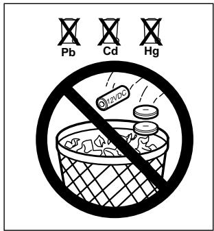
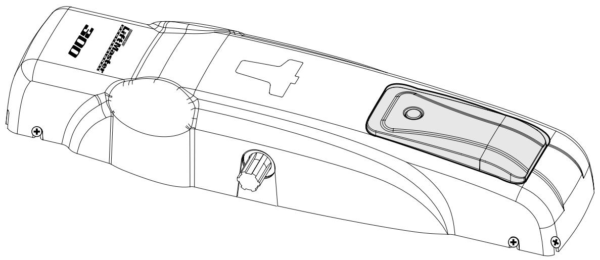
On the plexiglass cover there is a built-in switch (only BAS300K). This switch opens or closes the door at the press of a button. It is solid wired to the input St.1 for normal operation.
The controller/drive can be activated by different inputs. These can be initiated by hand transmitter or key switch.
- Hand transmitter = see section "Hand transmitter teach-in"
- Switch input 1 = input St.1, normal operation
- Switch input 2 = input St.2, active at special settings (see DIP switch SW2, Dip1 + Dip2)
DESCRIPTION OF POTENTIOMETER
The potentiometers are positioned in the middle of the controller and are arranged beside one another. Their values can be changed by means of a small screwdriver. Warning, turn carefully so that the component is not overwound. Turning clockwise increases the setting values.
The maximum running time of the controller is fixed at 40 seconds.
Potentiometers
OPEN Controls the force for the opening movement
CLOSE Controls the force for the closing movement
RPM Potentiometer for regulating the sensitivity of the speed sensor:
It controls the necessary time between 0-2s. Before reversing the operating direction 2s, then it stops.
Only active if the RPM sensor is installed. The speed sensor should always be set to be as sensitive as possible. Speed sensor: Plug CN3 on the controller.
DESCRIPTION OF POTENTIOMETER (CONTINUED)
The force, as measured on the closing edge of the door, should not exceed 600N (60kg). If the closing force is adjusted to more than 600N, Safety Edges must be installed.
Do not use force adjustments to compensate for a binding or sticking garage door. Excessive force will interfere with proper operation of the safety reverse system or damage the door.
Force Adjustment Controls are located on the control panel.
If the force adjustments are set too light, door travel may be interrupted by nuisance reversals in down direction and stops in up direction. Weather conditions can affect the door movement, occasional adjustment may be needed.
Maximum force adjustment range is 260 degrees, about 3/4 of a complete turn. Do not force controls beyond that point. Turn force adjustment controls with a screwdriver.
Test Down (Close) Force: Grasp the door handle or door bottom when door is about halfway through down (close) travel. Door should reverse. Reversal halfway through down travel does not guarantee reversal on a 50mm obstruction.
If the door is hard to hold or doesn't reverse, decrease down (close) force by turning the control in a counterclockwise direction.
Make small adjustments until door reverses normally. After each adjustment, run opener through a complete cycle.
DIP SWITCHES
Different programmes can be selected by means of the dip switches. It is advisable to only change the dip switches after completing the installation and to leave them at the factory setting for initial commissioning. To activate a new function the drive must be briefly isolated from the mains.
On = Push switch to "ON" position
Switchblock SW1 = Lower red switchblock
Switches 1+2
General setting of automatic operating logic - with automatic or manual closing. Only with connected and non-blocking failsafe photocell with pulsating signal (2-cable photocell).
No 1 No 2
| on | on | Automatic with 90 sec. pause in opening |
| off | on | Automatic with 60 sec. pause in opening |
| on | off | Automatic with 30 sec. pause in opening |
| off | off | Manual operation = factory setting |
Switches 3+4
Define the reaction of the drive when the limit switch is reached. A change in the factory setting is only necessary if for example the door cannot be completely closed. If the factory setting is changed the "close" limit switch must also be changed (beforehand), because the drive continues for 5 seconds after the limit switch has been reached (approx. 30 - 45^ ).
No 3 No 4
| on | on | Switches off immediately = factory setting |
| off | on | Soft - stop: Travels for 5 more secs. at slow speed. RPM sensor not active. |
on off Travels for 5 secs. more in normal speed RPM sensor not active.
off off
Travels for 4 secs. more at slow speed, then 1 sec. at normal speed. RPM sensor not active.
Switchblock SW2 = Upper red switchblock
| No1 | No2 | Switch input 1 (CH1 & ST1) | Switch input 2 (CH2 & ST2) |
| On | On | Standard operation = factory setting | |
| First pulse causes opening, the next causes a stop, the next closing, the next stop, the next opening etc. | |||
| Off | On | Channel separation operation: Only opening, only closing | |
| Input: A pulse causes opening, the next causes a stop, the next opening again, the next stop, etc. In automatic mode a pulse during the pause time causes the pause counter to restart. A pulse during the closing movement causes a stop, the next pulse re-opening. | Input: A pulse during opening leads to a stop, the next pulse to closing. A pulse during the pause time leads to an immediate re-closing in both automatic as well as manual operation. A pulse during the closing movement leads to a stop, the next pulse to closing, the next pulse to a stop, the next to closing etc. | ||
| On | Off | Group garage operation with channel separation | |
| Input: The first pulse causes opening, any further pulses from input 1 during the opening process are ignored. In automatic mode a pulse during the pause time causes the pause counter to restart. A pulse during the closing movement causes a stop, the next pulse re-opening. | Input: A pulse during opening leads to a stop, the next pulse to closing. A pulse during the pause time leads to an immediate closing in both automatic as well as manual operation. A pulse during the closing movement is ignored. | ||
| Off | Off | Dead man operation with channel separation | |
| Input: By pressing and holding down the pulse generator the door opens. If it is let go the door stops. In this case all the safety devices are NOT active. The limit switches are active; automatic closing not active. Radio not active. | Input: By pressing or holding down the pulse generator the system changes over to closing. If let go it stops. In this case all the safety devices are NOT active. The limit switches are active. Radio not active. | ||
PROGRAMMING THE REMOTE CONTROL
Factory setting of BAS300K: The transmitter programming takes place by means of the large button on CH1/St1 and the small button CH2/St2. If a radio module is provided in the right hand slot (only BAS300K) up to 15 transmitter buttons can be programmed. The controller has 2 channels which permit the different operating modes, see description DIP switch SW2 Dip 1+2. Two buttons are located on the right-hand edge of the controller marked CH1 and CH2. These are the programming buttons.
Programming:
- Press one of the buttons once briefly or until the LED beside the button switches on.
- After this press your selected button on the transmitter which should function. A successful programming is confirmed by a "click".
- Done.
- If you want to programm additional transmitters start again at step 1.
Clearing the transmitter:
- Press and hold down the button until the LED beside the programming button lights up (about 8 secs.) and goes out again.
- Done, all programmed transmitters on this channel are now cleared.
The range of the remote control system depends on the local conditions. Hold down the button on the hand transmitter (approx. 2 secs.) until movement of the door is seen.
Your remote controller is digitally coded, i.e. unintentional actuation of the door drive can be virtually excluded.
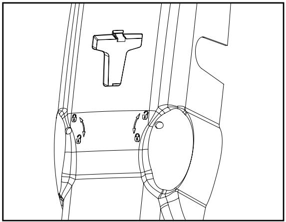
Remote Control Transmitter: The lithium batteries should produce power for up to five years. To replace batteries, use a screwdriver blade to pry open the case along the side where "Open" is stamped on the back. Insert batteries positive side down. To replace cover, snap shut along both sides.
Do not dispose of old batteries with household waste. Take batteries to a proper disposal center.
Additional remotes can be purchased at any time for use in all vehicles using garage. Refer to Accessories. The receiver must be programmed to operate with any new remote.
No 3 Initial push with maximum force at each end position of the door
On Active
Off Not active = factory setting
No 4 Pre-flashing function of flashing light, 2 secs. before start of each movement
On Active
Off Not active = factory setting
INITIAL OPERATION
Proceed cautiously and calmly. Take a lot of time over the basic settings. The time required for the initial setting can be up to 30 mins. A second person may be required to help so that changes to the controller can be made more simply (Power OFF or ON).
- Completely connect up the controller and drive including the safety inputs.
- Set all dip switches to the factory setting.
- Set the limit switches (see limit switch setting).
- Connect the drive to the mains power network. The lighting on the drive lights up. (Only BAS300K).
- The hand transmitters are ready programmed (only BAS300K).
- Set the "OPEN" "CLOSED" potentiometer to about 30% . In the case of very heavy doors somewhat higher. Fit the drive cover (only BAS300K)
- Manually move the door to a half open position and interlock the drive.
- Press the start button on the drive (only BAS300K) or press the programmed hand transmitter. If the door closes instead of opens the motor is incorrectly wired. The terminals on the controller must then be exchanged (brown/black). The cables are exchanged in which the capacitor is also connected. They determine the turning direction of the motors. Then repeat to make sure that the complete cycle takes place.
- Test a complete cycle and on the basis of this data set different, better values and repeat the procedure.
- The operating modes (dip switches) should only be changed if the end positions and the force have already been set.
- Once all settings have been made check the function of the photocells, buttons, flashing lights, hand transmitter, accessories etc. If you would like automatic closing you should now change the dip switch setting.
- Demonstrate to all those people, who will have to operate the door, the movement sequence of the door, how the safety functions work and how the drive can be actuated by hand.
CHECKS
Carry out a basic functional test on the drive and accessories. Hand over to the customer the page entitled "User Information", demonstrate the proper operation and use of the drive as well as showing them any potential hazards.
MAINTENANCE
The following steps should be carried out at least every 6 months:
- Checking the regulation of the motor torque.
- Check the rollers and guide rails on the door. Carry out cleaning and lubrication as necessary.
- Functional check of the interlock release system.
- Functional check of the safety equipment.
REPAIRS
The authorized Service Centres are responsible for repair work.
TECHNICAL DATA
| Model | BAS300K |
| Supply voltage | 230Volt |
| Frequency | 50Hz |
| Nominal power | 250W |
| Max. power | 400W |
| Max. torque | 350Nm |
| Capacitor | 10μF |
| Thermal protection | 140°C |
| Motor speed | 1400 rpm |
| Temperature | -20 to +5 |
| Operating frequency, cycles/hr | 20 |
| Weight | approx. 9kg |
| Type of protection | IP44 |
| Max. door width (m), 1 motor | 3 |
| Max. door height (m), 1 motor | 3 |
| Max. door area (m2), 1 motor | 8 |
| Max. door width (m), 2 motors | 5 |
| Max. door height (m), 2 motors | 3 |
| Max. door area (m2), 2 motor | 14 |
Declaration of Conformity
The undersigned, hereby declare that the equipment specified, and all accessories, conforms to the Directives and Standards stated.
Model: .BAS300K EN55014, EN61000-3, EN61000-4, ETS 300 683, EN 300 220-3, EN60335-1, and EN60335-2-95
√89/336/EEC
73/23/EEC
1999/5/EC
Declaration of Incorporation
A power door operator, in combination with a door must be installed and maintained according to all the Manufacturer's instructions, to meet the provisions of Machinery Directive, 89/392/EEC.
B. P. Kelkhoff
Manager, Regulatory Affairs
THE CHAMBERLAIN GROUP, INC.
Elmhurst, IL 60126
USA
May, 2004

Babba P. Keckhoo
Barbara P. Kelkhoff
Manager, Reg. Affairs
CONTACTLIJST (OPTIONEEL)
NOODSTOP (OPTIONEEL)
√89/336/EEC
73/23/EEC
√1999/5/EC
Inbouwverklaring
Manager, Regulatory Affairs
THE CHAMBERLAIN GROUP, INC.
Elmhurst, IL 60126
USA
May, 2004

Babana P. Keckhoff
Barbara P. Kelkhoff
Manager, Reg. Affairs
INDICACIONES IMPORTANTES PARA EL MONTAJE Y USO
√ 89/336/EEC
73/23/EEC
1999/5/EC
Manager, Reg. Affairs
ISTRUZIONI IMPORTANTI PER IL MONTAGGIO E L'USO
PER PRIMA COSA LEGGERE QUESTE IMPORTANTI NORME DI SICUREZZA!


Manager, Reg. Affairs
INSTRUÇÉS IMPORTANTES DE MONTAGEM E UTILIZAZão
√89/336/EEC
73/23/EEC
√1999/5/EC
Manager, Regulatory Affairs
THE CHAMBERLAIN GROUP, INC.
Elmhurst, IL 60126
USA
May, 2004

Barbarea P. Keckhoff
Barbara P. Kelkhoff
Manager, Reg. Affairs
BAS300K

Für Service: (49) 6838/907-172

Pour Service: 03-87-98-15-93

For Service: (+44) 0845-602-4285