
HB 750 - Jigsaw AEG - Free user manual and instructions
Find the device manual for free HB 750 AEG in PDF.
| Product type | Electric planer |
| Brand | AEG |
| Model | HB 750 |
| Power consumption | 750 W |
| Planing width | 82 mm |
| Depth of cut | 0 - 2,5 mm (adjustable) |
| Grooving depth | 0 - 22 mm |
| No-load speed | 13000 min⁻¹ |
| Weight | 3,7 kg |
| Power supply | Single-phase 230 V ~ 50 Hz |
| Sound pressure level (LpA) | 87 dB(A) |
| Sound power level (LwA) | 100 dB(A) |
| Vibration (forearm) | < 2,5 m/s² |
| Double insulation | Yes, according to DIN 57 740 / VDE 0740 |
| Main functions | Planing, grooving, chamfering, edge trimming |
| Depth adjustment | Graduated knob (0,1 mm per graduation) |
| Power switch lock | Yes, for safety |
| Swivel protective cover | With automatic return or by lever |
| Dust extraction connection | Yes (chips) |
| Beveled front sole | With V-groove for chamfering |
| Blade type | Reversible carbide, roughing, chip breaker |
| Routine maintenance | Clean ventilation openings, clean chip ejection |
| Annual brush check | Recommended by AEG after-sales service |
| Spare parts | Planer blades, tension elements, parallel guide, rebate guide |
| Optional accessories | Collection bag, extraction adapter, parallel guide, rebate guide |
Frequently Asked Questions - HB 750 AEG
User questions about HB 750 AEG
0 question about this device. Answer the ones you know or ask your own.
Ask a new question about this device
Download the instructions for your Jigsaw in PDF format for free! Find your manual HB 750 - AEG and take your electronic device back in hand. On this page are published all the documents necessary for the use of your device. HB 750 by AEG.
USER MANUAL HB 750 AEG
GB Instructions for use
Please read and save these instructions.
| Introduction | You demand the best and buy quality - quality provided by Atlas Copco. We have built for you a reliable and lasting tool. Working effectively and without endangering your health is only possible if these instructions for use are being read carefully before first using this tool. We want to satisfy our customers and would like you to buy again AEG Electric Power Tools from Atlas Copco. |
| Technical Data | H 500 H 750 HB 750 HBE 800 Nominal power 500 W 750 W 750 W 800 W Planing width 82 mm 82 mm 102 mm 102 mm Planing depth 0-1,6 mm 0-2,5 mm 0-2,0 mm 0-2,0 mm Rabbit depth 0-16 mm 0-22 mm 0-22 mm 0-22 mm No-load speed 17000 min-1 13000 min-1 13000 min-1 11000 min-1 Weight 2,5 kg 3,5 kg 3,7 kg 3,8 kg |
| Advice for your safety | Please pay attention to the safety instructions in the attached leaflet! Appliances used at many different locations including open air must be connected via a current surge preventing switch. Always use the protective shields on the machine. Always wear goggles when using the machine. It is recommended to wear gloves, sturdy non-slipping shoes and apron. Sawdust and splinters must not be removed while the machine is running. Do not pierce the motor housing as this could damage the double insulation (use adhesives). Always disconnect the plug from the socket before carrying out any work on the machine. Keep mains lead clear from working range of the machine. Always lead the cable away behind you. Before switching on ensure that protective swing cover moves freely. Only plane with sharp blades and avoid metal (nails, screws). When doing stationary planing (not rabbeting) use the guard. For stationary operation, for trimming small pieces of wood also use push stick. Only put the planer down after the blades have stopped moving. The protective swing cover and the blade drive cover on the side must be easy to move to and fro. The protective swing cover must not be locked open except when the plane is beeing used in afixed mounting. Operate the protective swing cover only by means of the lever or automatically by pressure against the piece being planed. In the fixed position, the plane may only be used in the Atlas Copco stationary mounting or in the Atlas Copco dressing and planing table. Do not put the machine down until the blade drive has stopped running. Never reach into the danger area of the plane when it is running. |
| Measured sound value | Typically the A-weighted noise levels of the tool are: Sound pressure level = 87 dB (A). Sound power level = 100 dB (A). Wear ear protectors! |
| Measured vibration value | Typically the hand-arm vibration is below 2.5 m/s². |
| Use | The plane can plane surfaces and rabetts, and bevel and chamfer edges. Do not use this product in another way as stated for normal use. |
| Mains connection | Connect only to a single-phase AC current supply and only to the mains voltage specified on the rating plate. Connection to sockets without earth protection is possible as the appliance features protective insulation to DIN 57 740/ VDE 0740 and CEE 20. Radio suppression complies with the European standard EN 55014. When fitting the plug, make sure that the brown (live) wire of this appliance is connected to the plug terminal marked L or coloured red, and the blue (neutral) wire of this appliance is connected to the plug terminal marked N or coloured black. Under no circumstances must the wires of this appliance be connected to the earth terminal of the plug marked either E, with the earth symbol or coloured green or green/yellow. |
| Accessories | The range of accessories with part numbers is shown in our catalogue. |
| ENGLISH | H 500, H 750, HB 750, HBE 800 |
Brief description
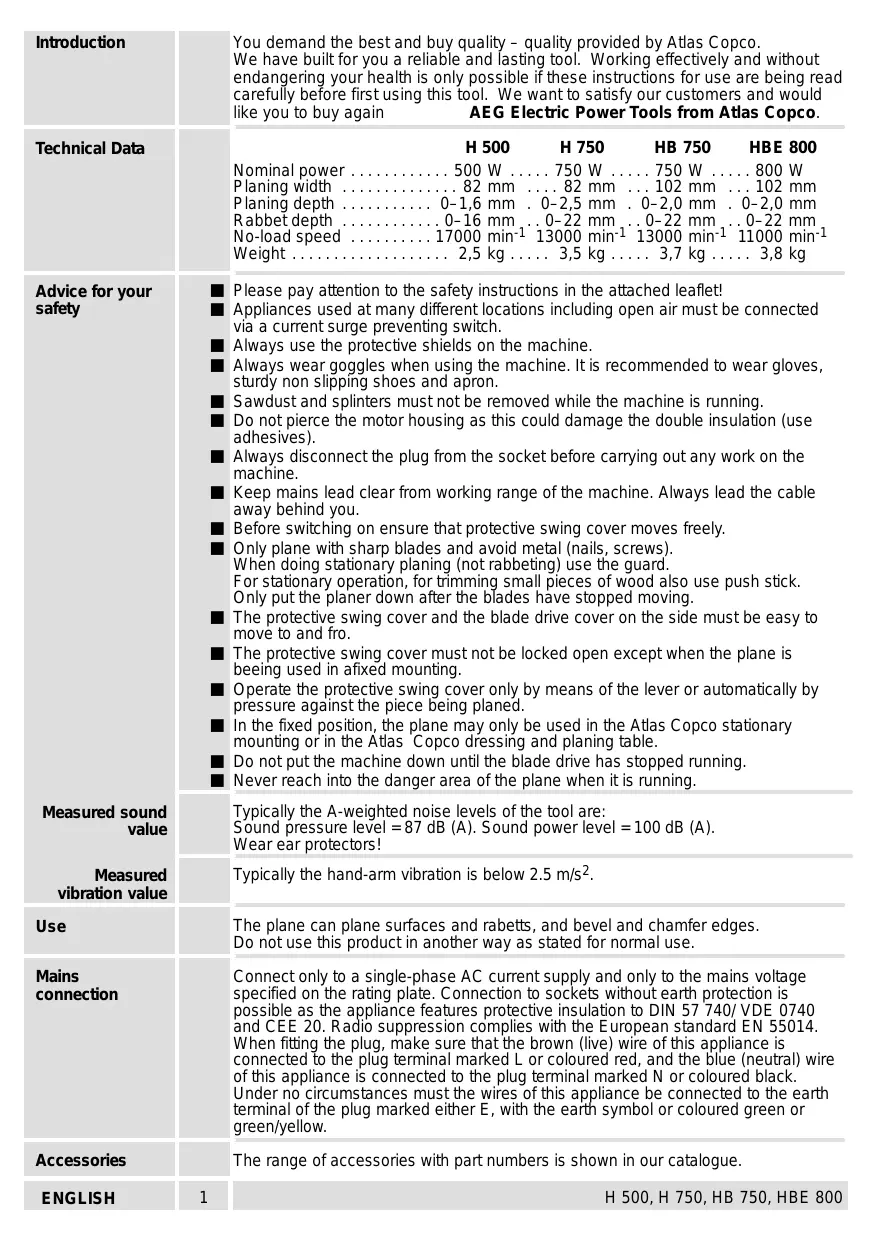
Switching on the machine is only possible when pressing the switch-lock (for your safety).
On-/off switch
The planing depth can be infinitely varied by means of the adjusting wheel.
Limited r.p.m. in neutral reduces operating noise - the r.p.m. are reduced when the machine is not under load. (only applicable for HBE 800)
Integrated suction channel for connection to a vacuum-cleaner.
Blade drive cover swings back automatically when rabetting.
Hard metal cutters, old-fashioned plane blades (for rough- planing with adze-marks), and plane blades with grooves for splitting shavings (for easier shavings discharge at greater planing depths), can be fitted into the blade drive shaft. The old-fashioned plane blades and the grooved plane blades are available as accessories.
The base of the plane is angled so that it can be brought on to the material more accurately, and is fitted with a V-shaped groove for chamfering edges.
On/off switch

For safety reasons this power tool is fitted with a switch lock and the On-/Off switch cannot be locked in the "On" position.
Switching on:
Press switch lock (1) and then On-/off switch (2).
Switching off:
Release On-/Off switch.
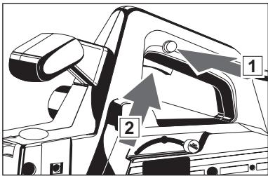
Protective swing cover swings back automatically or can be operated by hand using the lever.
Modifications: Text, diagrams and data are correct at the time of printing. In the interest of continuous improvement of our products, technical specifications are subject to alteration without prior notice.
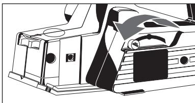
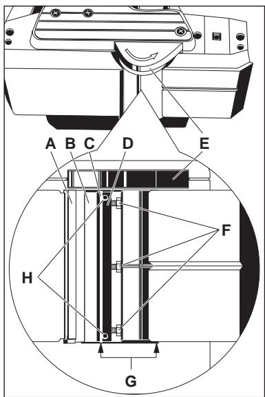
Changing the plane blade

Always disconnect the plug from the socket before carrying out any work on the machine.

As soon as one of the edges of the plane blades becomes blunt please turn plane blade or if worn out replace planer blades (only in pairs!).
- Swing the protective cover back using the lever and hold it firmly.
- Loosen the screws (F) by turning them to the right.
- Press the blade drive cover (E) down and pull the tension unit (D) out to the side complete with the planer blade.
- Pull the planer blade out of the tension unit.
- Clean the tension unit (D) and the blade drive shaft (B).
- Push the new planer blade all the way in at the side of the tension unit, making sure that the cam on the tension unit fits into the groove in the planing blade.
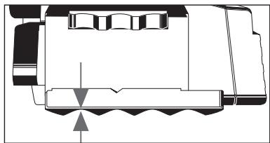
- Push the tension unit with the new planer blade into the drive shaft so that the edge of the planer blade is level with the edge of the housing (G).
- Press the tension unit against the drive shaft and fasten it by turning the screws (F) to the left.
- Turn the drive shaft through 180^ and change the second set of planer blades as described.

Do not move the adjusting screws (H) – the tension unit is adjusted in the factory.

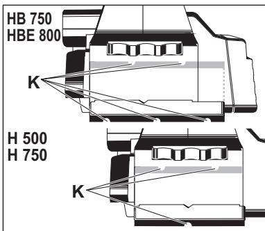
When using the grooved planer blades (K), always use two blades with a different number of grooves.

Check that the planer blades do not rub against the housing.

Always change both planer blades and both tension units at once.
Fitting old-fashioned planing blades
Always fit the old-fashioned planing blades complete with the appropriate tension unit.
Fit the planing blades and the tension unit into the blade drive shaft and tigten them with the adjusting screws just enough so that the deepest points on the corrugated blade line up with the plane base.
Adjusting wheel must be set to "0".
Make sure that the planing blade and the base of the plane are parallel to one another.
Set planing depth to 0.2mm (max 0.4mm ) with adjusting wheel.
| Setting the planing depth | With setting wheel. The notches represent 0,1 mm cutting depth. In setting "P" (parking) the planer blades are recessed in the housing. | ||
| Sawdust removal (Accessory*) | A dust bag or suction hose with adaptor can be attached to the machine for sawdust removal with an wet- and- dry vacuum cleaner. *Not included in standard equipment, available as an accessory. | ||
| Parallel fence (Accessory*) | The planing/chanfering width can be set on the scale after attaching the rip fence. *Not included in standard equipment, available as an accessory. | ||
| Chamfering depth gauge (Accessory*) | The chamfering depth of 0–16 mm can be set on the chamfering depth gauge. *Not included in standard equipment, available as an accessory. | ||
| Advice for operation | Never reach into the danger area of the plane when it is running. Place the front page of the machine on to the worpiece and switch on, before the planer blade touches the workpiece. The selv opening swivel guard closes itself when the machine is lifted, but can laso be effected with lever and then guide evenly over the workpiece. The v-shape notch in the front of the supporting plate ensures safe chamfering of edges. To adjut cutting depth first set on "P". Then adjust to the necessary setting according to required chamfering depth. | ||
| Maintenance | The ventilation slots of the machine must be kept clear at all times. If the shavings discharge is stained with resin, remove it with a cloth soaked in turpentine substitute. In order to guarantee constant readiness for operation, the machine should be checked for worn carbon brushes at one of the AEG after-sales service agencies. Use only AEG accessories and spare parts. Should components need to be replaced which have not been described, please contact one of our AEG service agents (see our list of guarantee/service addresses). If needed, an exploded view of the tool can be ordered. Please state the ten-digit No. as well as the machine type printed on the label and order the drawing at your local service agents or directly at: Atlas Copco Electric Tools GmbH, Postfach 320, D-71361 Winnenden. | ||
| ENGLISH | 4 | H 500, H 750, HB 750, HBE 800 | |
No Change in the current state.
No change in the current state.
No change in the current state.
No change in the current state.
No change in the current state.

He nobopauBaIte peyInpoBOUHbIe BnHTbI (H)-HaTJXHOe yCTpOiCTBO OTepeyInpoBAHO Ha 3aBoJe.

PnI NcNoJIb3OBAHmN Ie3BnI C npOTOnkAMn (K) BcerJa NcNoJIb3yUte Da Ie3BnIC pa3JIuHbIM YNCJOM KaHABOK.

EC-DECLARATION OF CONFORMITY
We declare under our sole responsibility that this product is in conformity with the following standards or standardized documents. EN 50144, EN 55014-1, EN 55014-2, EN 60555, HD 400 in accordance with the regulations 98/37/EC, 73/23/EC, 89/336/EC
DEUTSCH
DECLARATION "CE" DE CONFORMITÉ
CE-KONFORMITETSERKL/ERING
D-71361 Winnenden Germany
http://www.atlascopco.de

Brand : AEG
Model : HB 750
Category : Jigsaw