
NP01TM - Projector Accessory NEC - Free user manual and instructions
Find the device manual for free NP01TM NEC in PDF.


| Product type | Projector accessory (mount/filter/adapter) |
| Compatibility | NEC NP series projectors, specific model NP01TM |
| Dimensions (L x W x H) | 150 x 80 x 30 mm |
| Weight | 0.25 kg |
| Main material | ABS plastic and metal |
| Color | Black |
| Operating temperature | 0 °C to 40 °C |
| Relative humidity | 20% to 80% (non-condensing) |
| Power supply | None (passive) |
| Warranty | 2 years (parts and labor) |
| Installation | Wall or ceiling mount (depending on provided kit) |
| Main functions | Projector mount, angle adjustment, cable management |
| Maintenance and cleaning | Clean with a soft, dry cloth. Do not use solvents. |
| Safety | Do not exceed maximum load of 5 kg. Check the mount regularly. |
| Spare parts and repairability | Spare parts available from NEC. Repair by authorized center. |
| Package contents | NP01TM accessory, mounting kit, user manual |
| Certifications | CE, RoHS |
| Country of origin | Japan |
| Manufacturer reference | NP01TM |
Frequently Asked Questions - NP01TM NEC
User questions about NP01TM NEC
0 question about this device. Answer the ones you know or ask your own.
Ask a new question about this device
Download the instructions for your Projector Accessory in PDF format for free! Find your manual NP01TM - NEC and take your electronic device back in hand. On this page are published all the documents necessary for the use of your device. NP01TM by NEC.
USER MANUAL NP01TM NEC
natural_image
Line drawing of a laptop connected to a wall-mounted device, showing internal components and wiring (no text or symbols)English
Deutsch
Français
Italiano
Español
Português
Русский
Türkçe
Polski
한글
日本語


natural_image
Vertical arrangement of black rectangular blocks with white borders, no text or symbols presentTouch Module
NP01TM
Installation Manual
CONTENTS
Introduction 2
Disposing of your used product.... 2
Read This Before Starting 4
Location to Mount the Touch Module and Mounting Procedure ..... 6
-
Packaged Items ...... 7
-
Parts Names ...... 7
Front face 7
Cover Inside....8
Rear Face 8
-
Setup Procedure 9
-
Download the Software Program 9
-
Mount the Touch Module at the Top of the Screen.... 10
-
Connecting the USB Cable 12
-
How to Use the Antireflection Sheet 13
-
Specifications ...... 14
Thank you for purchasing the NEC Touch Module, NP01TM, hereinafter called the touch module or this product in this manual.
By connecting this product to an NEC projector in combined use with an interactive white board kit, it enables to draw on a screen by fingers instead of using a stylus pen.
Finger touch operation can not be carried on only by this product in independent use.
Make sure to use this product in combined use with the interactive whiteboard kit (camera unit).
Supported interactive whiteboard kit (as of Feb. 2015)
NP03Wi
Supported projectors (as of Feb. 2015)
NP-M352WS, NP-M302WS, NP-M332XS,
NP-UM351W, NP-UM301W, NP-UM361X, NP-UM301X,
NP-UM280X, NP-UM330X, NP-UM280W, NP-UM330W
Disposing of your used product

EU-wide legislation as implemented in each Member State requires that used electrical and electronic products carrying the mark (left) must be disposed of separately from normal household waste. When you dispose of such products, please follow the guidance of your local authority and/or ask the shop where you purchased the product.
After collecting the used products, they are reused and recycled in a proper way. This effort will help us reduce the wastes as well as the negative impact such as mercury contained in parts to the human health and the environment at the minimum level.
The mark on the electrical and electronic products only applies to the current European Union Member States.
Products and company names mentioned in this installation manual may be the trademarks or registered trademarks of their respective holders.
Note:
(1) Unauthorized reprinting of the contents of this manual is prohibited.
(2) The contents of this manual are subject to change in the future without notice.
(3) The contents of this manual have been prepared with scrupulous care, but please notify NEC should you have any doubts or notice any mistakes or omissions.
(4) Please note that NEC will accept no responsibility whatsoever for claims for damages, lost earnings, etc., arising from the use of this product, regardless of article (3) above.
(5) NEC will replace any manuals presenting incorrect collation or missing pages.
DOC Compliance Notice (for Canada only)
This Class B digital apparatus complies with Canadian ICES-003.
RF Interference (for USA only)
WARNING
The Federal Communications Commission does not allow any modifications or changes to the unit EXCEPT those specified by NEC Display Solutions of America, Inc. in this manual. Failure to comply with this government regulation could void your right to operate this equipment. This equipment has been tested and found to comply with the limits for a Class B digital device, pursuant to Part 15 of the FCC Rules. These limits are designed to provide reasonable protection against harmful interference in a residential installation. This equipment generates, uses, and can radiate radio frequency energy and, if not installed and used in accordance with the instructions, may cause harmful interference to radio communications. However, there is no guarantee that interference will not occur in a particular installation.
If this equipment does cause harmful interference to radio or television reception, which can be determined by turning the equipment off and on, the user is encouraged to try to correct the interference by one or more of the following measures:
• Reorient or relocate the receiving antenna.
- Increase the separation between the equipment and receiver.
- Connect the equipment into an outlet on a circuit different from that to which the receiver is connected.
- Consult the dealer or an experienced radio / TV technician for help.
WARNING TO CALIFORNIA RESIDENTS:
Handling the cables supplied with this product will expose you to lead, a the State of California to cause birth defects or other reproductive harm. WASH HANDS AFTER HANDLING.
chemical
DECLARATION OF CONFORMITY
This device complies with Part 15 of FCC Rules. Operation is subject to the following two conditions. (1) This device may not cause harmful interference, and (2) this device must accept any interference received, including interference that may cause undesired operation.
U.S.Responsible Party: NEC Display Solutions of America, Inc.
Address: 500 Park Boulevard, Suite 1100
Itasca, Illinois 60143-1248
Tel. No.: (630) 467-3000
Type of Product: Touch Module
Equipment Classification: Class B Peripheral
Model No.: NP01TM

We hereby declare that the equipment specified above conforms to the technical standards as specified in the FCC Rules.
About the pictograms
To ensure safe and proper use of the product, this installation manual uses a number of pictograms to prevent injury to you and others as well as damage to property.
The pictograms and their meanings are described below. Be sure to understand them thoroughly before reading this manual.
 WARNING WARNING | Failing to heed this pictogram and handling the product erroneously could result in accidents leading to death or major injury. |
 CAUTION CAUTION | Failing to heed this pictogram and handling the product erroneously could result in personal injury or damage to surrounding property. |
Examples of pictograms
 | The △ symbol indicates instructions urging caution (including warnings). A concrete indication of the caution is given within the symbol. |
 | The Symbol indicates prohibited actions. A concrete indication of the prohibited action is given within the symbol. |
 | The ● symbol indicates required actions. A concrete indication of the required action is given within the symbol. |

WARNING
 | Laser Safety Caution• Laser diode is sealed in this product. Use of controls or adjustments of procedures other than those specified herein may result in hazardous radiation exposure.• This product is classified as Class 1 of IEC60825-1:2007.• The caution and explanatory labels of the CLASS 1 LASER PRODUCTS is on the side face of this product body.  | |
WARNING
 | Do not look into the laser diffusion part while the touch module is on. Serious damage to your eyes could result.The following caution pictogram is indicated near the laser diffusion part. Keep any optical items (a loupe, a reflecting mirror, etc.) out of the projection screen area. Visual impairment could result. Keep any optical items (a loupe, a reflecting mirror, etc.) out of the projection screen area. Visual impairment could result. |
  | Do not remove any screws besides the specified screws in this installation manual for mounting /demounting this product.Do not disassemble and remodel. Do not subject this product to shock or excessive forces. It may cause of fire, shock and laser light leakage.Contact your dealer for the inspection, adjustment and repair. |
 | Do not place this product in damp place. Avoid dripping or splashing water near this product. If water has been spilled into this product, contact your dealer. |
 | Do not insert any metal or flammable objects. It may cause of fire and shock. Pay enough attention to children. If something should fall into this product, disconnect the USB cable connecting with the projector and contact your dealer. |
 | The power for this product is supplied from the USB port on the supported projector via the USB cable supplied with this product.Wrong connection may cause of fire and shock. |
CAUTION

- If the touch module is mounted with the built-in magnets, take appropriate countermeasure from falling down. If not, the touch module may fall down and may cause of injury.
Take security measure by an item supports the MicroSaver® security system.
Location to Mount the Touch Module and Mounting Procedure
- The touch module is not used outdoor and in the area direct sunlight or strong light strikes the screen surface. Operation in bright circumstance as beside a window, near a fi lament lamp, or a halogen lamp issues much infrared light may cause of malfunction.
- Mount the touch module onto a screen of which surface deflection is within 8mm. For smooth operations, recommend to use a screen which surface deflection is within 3mm.
• The touch module usable screen size is from 60" to 100". - For using the touch module, install the projector by a wall mount unit, a ceiling mount unit, or a table mount unit. If the projector installed on a desktop, the touch module cannot be used.

natural_image
Pure technical line drawing of a mechanical assembly or clamp device without any text, numbers, or symbols
natural_image
Line drawing of a simple table setup with a monitor and lamp on top, no text or symbols present- Mount the touch module at the position as the below illustration considering the image projection area.

* Pay attention to mount not to cut into the projection light.
• For securing the touch module, use the built-in magnet or commercially available screws.
- For using commercially available screws, prepare two (2) bolts of which nominal diameter is 3mm. Choose an appropriate bolt to your circumstances.
- For securing the touch module, use the built-in magnet or commercially available screws. - For using commercially available screws, prepare two (2) bolts of which nominal diameter is 3mm. Choose an appropriate bolt to your circumstances.
1. Packaged Items
Make sure your box contains everything listed. If any pieces are missing, contact your dealer.
 | Touch ModuleMount at the top of a screen or a white board projected an image by a projector. |
 | USB cable (3.0 m / 118 inches) x 1 (*For power supply)7N520086 For connecting the USB port on the touch module (type B) and the USB port on a projector (type A) |
 | Antireflection sheet (Length 175 mm / 7 inches, 12 pcs)For hiding bumps and obstructions around the screen that disables to draw utilizing the touch module. |
 | Installation manual (this document) |
2. Parts Names
Front face

Cover Inside


CAUTION
- When the touch module is mounted on a screen or a white board by magnets, hold the touch module and then remove the cover. Otherwise, the touch module may fall down and may cause of injury.
Rear Face

Caution:
- Do not touch the laser diffusion ports. It may cause of malfunction.
Note:
The security slot supports the MicroSaver® Security system.
3. Setup Procedure
STEP 1 Download and install the software program onto the computer.

STEP 2 Connect the interactive whiteboard kit to the projector for enable to use the stylus pen.

STEP 3 Perform the calibration of the camera.

STEP 4 Mount the touch module at the top of the screen.

STEP 5 Connect the USB cable.

STEP 6 Perform the touch module adjustment.
Note:
- Concerning to details of the STEP1 (How to install the software program), the STEP3 (How to calibrate the camera), and the STEP6 (How to adjust the touch module), refer to the software manual that is available from our company website.
4. Download the Software Program
Perform the calibration of the camera unit for the interactive whiteboard kit and adjustment of the touch module for using the touch module.
The exclusive software program is available from our company website. Please visit our support site also about operational conditions as supported OS:
URL: http://www.nec-display.com/dl/en/index.html
PDF (Portable Document Format) explains the operations of camera calibration by the software program and adjustment of the touch module is available. To view or print the PDF files Adobe Reader ^™ is required.
5. Mount the Touch Module at the Top of the Screen
- Built-in magnets are loaded on the rear face of the touch module as the factory default setting. No need to secure the touch module by screws on a screen or a white board that attracts magnets.
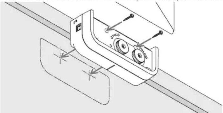
- For using the touch module on a screen or a white board that does not attract magnets, remove the built-in magnet from the rear face of the touch module and secure the touch module with commercially available screws.
- Use commercially available screws (2 pcs) in nominal diameter 3 mm. Prepare bolts that are appropriate for your circumstances.
- Project the adjustment screen in the software program. The center position adjustment line would be displayed, Align this with the centering line on the touch module.
- Refer to page 5 about the touch module mounting procedures by the table projection mount unit.
Note:
- Do not connect the USB cable before mounting the touch module onto the screen.
[1] Decide the position to mount the touch module referring the below picture.
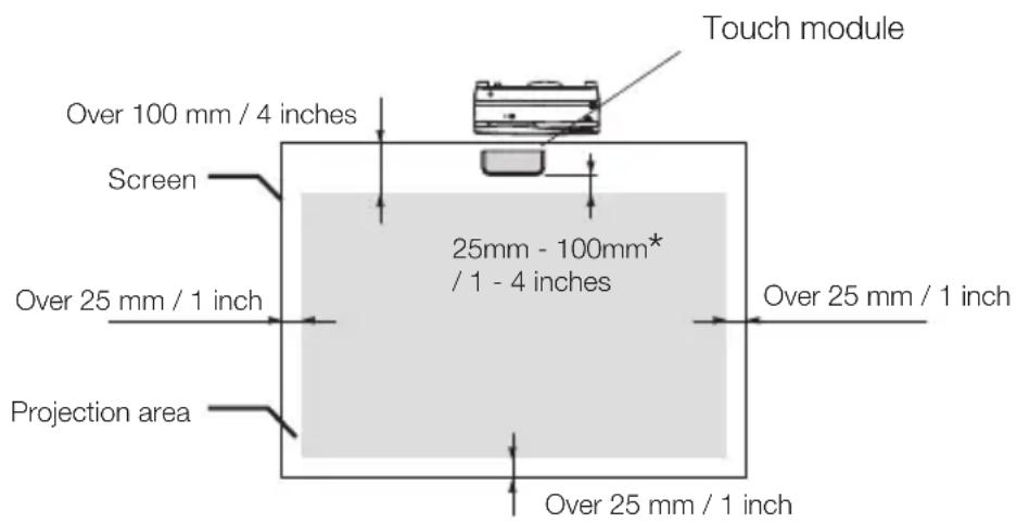
* Pay attention to mount not to cut into the projection light.
[2] Mount the touch module onto the screen.
Mounting by the built-in magnets
- Put the rear face of the touch module onto a screen or a whiteboard since the touch module has built-in magnets on its rear face as the factory default setting.
- In case, mounting the touch module by the built-in magnets, take appropriate countermeasure from falling down. Prepare the commercially available Kensington security wire and connect it to the security slot on the touch module.
Mounting by commercially available screws
IMPORTANT
- Before mounting the touch module by commercially available screws, make sure the adjustment of the touch module (hereinafter described) can be performed properly. Please consider temporally mount until proper performance of adjustment can be checked. Take preventive measure from falling down for the temporally mount, too.
- Utilize the magnet set holes for mounting the touch module by screws.
Remove the magnets from the touch module by a plus headed Phillips driver. Keep the removed magnets and screws.

natural_image
Technical line drawing of a mechanical device with gears and buttons (no text or symbols)- Mount the touch module onto a screen or a white board by commercially available screws.
natural_image
Technical line drawing of a mechanical device with gears and adjustment knobs (no text or symbols)Reference
- For using the table projection mount unit, secure the touch module by a commercially available double sided adhesive tape sealed on the rear face of the touch module.
Prepare the double sided adhesive tape of which thickness is in the range from 1.2 mm to 1.5 mm.

natural_image
Isometric line drawing of a device casing with buttons and a switch (no text or symbols)
CAUTION
- Do not use a double sided adhesive tape besides for mounting the touch module on a table. It may cause of injury by fallen down touch module.
6. Connecting the USB Cable
Connect the USB port (type B) on the touch module and the USB port (type A) on the projector by the USB cable supplied with the touch module.
• Make sure the projector and the computer are connected by the computer cable.
- Make sure the camera unit and the computer are connected by the USB cable. (for the optional interactive whiteboard kit)
Note:
- Do not connect to the USB port on the projector for a wireless LAN unit.

7. How to Use the Antireflection Sheet
Use the antireflection sheet supplied with the touch module when finger drawing is disabled caused on reflection issued by an object laying at the bottom of a screen such as a pen tray, a whiteboard or a screen frame, etc. Stick on the antireflection sheet to cut the laser beam diffused by the touch module not to hit the reflection caused object.
Note:
- Do not peel off the reflection sheet once it's stuck. Repetition of sticking on and off will deteriorate the adhesive force of the sheet.

8. Specifications
| Model name NP01TM | |
| Laser class Class 1 (IEC60825-1:2007) | |
| Internal laser diode Total laser power: 200 mW ( ×2 pcs)Wavelength: 830 nm | |
| Input terminal USB Type B x 1 | |
| Power requirement /Nominal electric current | DC5V / 400 mA |
| Power consumption 2W | |
| Weight 290 g / 0.64 lbs | |
| External Dimensions 190(W) | × 74.5(D) × 56.8 (H) (unit in mm) / 7.48(W) × 2.93(D) × 2.24(H) (unit in inch) (not including protrusion) |
| Effective range 60 to 100 inches | |
| Operating temperature and humidity | 5° to 40°C (41° to 104°F) 20% to 80% (non-condensing) |
| Storage temperature and humidity | -10° to 50°C (14° to 122°F) 20% to 80% (noncondensing) |
Berührungsmodul
NP01TM
NP-M352WS, NP-M302WS, NP-M332XS,
NP-UM351W, NP-UM301W, NP-UM361X, NP-UM301X,
NP-UM280X, NP-UM330X, NP-UM280W, NP-UM330W
natural_image
Technical line drawing of a mechanical assembly or clamp device mounted on a rectangular frame (no text or symbols visible)
natural_image
Line drawing of a simple table with a monitor and a small object on top (no text or symbols)natural_image
Technical line drawing of a mechanical device with gears and buttons (no text or symbols)natural_image
Technical line drawing of a mechanical device with gears and adjustment knobs (no text or symbols)Referenz
natural_image
Isometric line drawing of a device casing with buttons and a switch (no text or symbols)
VORSICHT
NP-M352WS, NP-M302WS, NP-M332XS,
NP-UM351W, NP-UM301W, NP-UM361X, NP-UM301X,
NP-UM280X, NP-UM330X, NP-UM280W, NP-UM330W
natural_image
Technical line drawing of a mechanical assembly or assembly with no visible text or symbols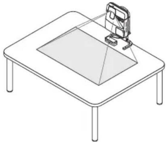
natural_image
Line drawing of a simple table setup with a monitor and a small object on top (no text or symbols)natural_image
Isometric line drawing of a mechanical device with gears and buttons (no text or symbols)natural_image
Technical line drawing of a mechanical device with gears and adjustment knobs (no text or symbols)Référence
natural_image
Isometric line drawing of a device casing with buttons and a switch, no text or symbols present
MISE EN GARDE
8. Caractéristiques
NP-M352WS, NP-M302WS, NP-M332XS,
NP-UM351W, NP-UM301W, NP-UM361X, NP-UM301X,
NP-UM280X, NP-UM330X, NP-UM280W, NP-UM330W
natural_image
Technical line drawing of a mechanical assembly or clamp device mounted on a rectangular frame (no text or symbols visible)
natural_image
Line drawing of a simple table setup with a monitor and a triangular screen on top (no text or symbols)natural_image
Technical line drawing of a mechanical device with gears and buttons (no text or symbols)natural_image
Technical line drawing of a mechanical device with gears and adjustment knobs (no text or symbols)Riferimento
natural_image
Isometric line drawing of a device casing with buttons and a labeled component (no text or symbols)
ATTENZIONE
NP-M352WS, NP-M302WS, NP-M332XS,
NP-UM351W, NP-UM301W, NP-UM361X, NP-UM301X,
NP-UM280X, NP-UM330X, NP-UM280W, NP-UM330W
natural_image
Technical line drawing of a mechanical assembly or clamp device mounted on a rectangular frame (no text or symbols visible)
natural_image
Line drawing of a simple table setup with a monitor and a triangular screen, no text or symbols present.natural_image
Technical line drawing of a mechanical device with gears and buttons (no text or symbols)natural_image
Technical line drawing of a mechanical device with gears and adjustment knobs (no text or symbols)Referencia
natural_image
Isometric line drawing of a device casing with ports and connectors (no text or symbols)
PRECAUCIÓN
8. Especificaciones
NP-M352WS, NP-M302WS, NP-M332XS,
NP-UM351W, NP-UM301W, NP-UM361X, NP-UM301X,
NP-UM280X, NP-UM330X, NP-UM280W, NP-UM330W
natural_image
Technical line drawing of a mechanical assembly or assembly with no visible text or symbols
natural_image
Line drawing of a simple table setup with a monitor and lamp on top, no text or symbols presentnatural_image
Technical line drawing of a mechanical device with gears and buttons (no text or symbols)natural_image
Technical line drawing of a mechanical device with gears and adjustment knobs (no text or symbols)Referência
natural_image
Isometric line drawing of a device casing with buttons and mounting holes (no text or symbols)
CUIDADO
8. Especificações
NP-M352WS, NP-M302WS, NP-M332XS,
NP-UM351W, NP-UM301W, NP-UM361X, NP-UM301X,
NP-UM280X, NP-UM330X, NP-UM280W, NP-UM330W
natural_image
Line drawing of a rectangular electronic device with ports and buttons (no text or symbols)⚠️ ПРЕДУПРЕЖДЕНИЕ
natural_image
Diagram of a mechanical assembly with a clamping device and lever mechanism (no text or symbols)
natural_image
Line drawing of a simple table setup with a monitor and tripod on top, no text or symbols presentnatural_image
Technical line drawing of a mechanical device with gears and buttons (no text or symbols)natural_image
Technical line drawing of a mechanical device with two wheels and adjustment knobs, mounted on a diagonal surface (no text or symbols)Справка
natural_image
Isometric line drawing of a device casing with buttons and a switch (no text or symbols)
ВНИМАНИЕ
NP-M352WS, NP-M302WS, NP-M332XS,
NP-UM351W, NP-UM301W, NP-UM361X, NP-UM301X,
NP-UM280X, NP-UM330X, NP-UM280W, NP-UM330W
natural_image
Diagram of a mechanical assembly or cleaning device mounted on a rectangular frame, with no visible text or symbols.
natural_image
Line drawing of a simple table setup with a monitor and a small object on top (no text or symbols)natural_image
Isometric line drawing of a mechanical device with gears and buttons, no text or symbols presentnatural_image
Technical line drawing of a mechanical device with gears and adjustment knobs, mounted on a diagonal surface (no text or symbols)Referans
natural_image
Isometric line drawing of a device casing with buttons and a switch, no text or symbols present
DİKKAT
NP-M352WS, NP-M302WS, NP-M332XS,
NP-UM351W, NP-UM301W, NP-UM361X, NP-UM301X,
NP-UM280X, NP-UM330X, NP-UM280W, NP-UM330W
natural_image
Technical line drawing of a mechanical assembly or clamp device mounted on a rectangular frame (no text or symbols visible)
natural_image
Line drawing of a simple table setup with a monitor and a small object on top (no text or symbols)natural_image
Technical line drawing of a mechanical device with gears and adjustment knobs (no text or symbols)Informacje
natural_image
Isometric line drawing of a device casing with buttons and a switch, no text or symbols present
PRZESTROGA
NP-M352WS, NP-M302WS, NP-M332XS,
NP-UM351W, NP-UM301W, NP-UM361X, NP-UM301X,
NP-UM351WiK, NP-UM361XiK,
NP-UM280X, NP-UM330X, NP-UM280W, NP-UM330W
사용된 제품을 폐기

natural_image
Diagram of a mechanical assembly or cleaning device with a clamped component and transparent panel (no text or symbols)
natural_image
Line drawing of a simple table setup with a monitor and a tray, no text or symbols presentnatural_image
Isometric line drawing of a mechanical device with gears and buttons, no text or symbols presentnatural_image
Technical line drawing of a mechanical device with gears and adjustment knobs (no text or symbols)참고
natural_image
Isometric line drawing of a device casing with ports and connectors (no text or symbols)
주의사항
NP-M352WSJD、NP-M302WSJD、NP-UM351WJL、NP-UM361XJL、NP-UM330XJL、NP-UM330WJL
natural_image
Pure technical diagram of a mechanical assembly or clamp device without any text, numbers, or symbols
natural_image
Line drawing of a simple table with a monitor and a small object on top (no text or symbols)natural_image
Technical line drawing of a mechanical component with adjustment knobs and mounting brackets (no text or symbols)参考
natural_image
Isometric line drawing of a device casing with buttons and a switch (no text or symbols)
注意
8. 仕様
This warranty is valid only in Japan.
| 年 | 月 日 | サービス内容 担当者 | |
, NP-UM301X , NP-UM361X , NP-UM301W , NP-UM351W
, NP-UM330W , NP-UM280W , NP-UM330X , NP-UM280X
natural_image
Diagram of a mechanical assembly or cleaning device with a frame and lever mechanism (no text or symbols)
natural_image
Line drawing of a simple table setup with a monitor and a screen on top, no text or symbols present.natural_image
Technical line drawing of a mechanical device with gears and adjustment knobs, mounted on a diagonal surface (no text or symbols)
natural_image
Isometric line drawing of a device casing with buttons and ports (no text or symbols)المرجع
Turkish RoHS information relevant for Turkish market
Ukrainian RoHS Information relevant for Ukrainian market
D-80637 München, Germany
Telephone: +49 89 99699 0
Email: infomail@nec-displays.com
In North America
NEC Display Solutions of America, Inc.
Address: 500 Park Boulevard, Suite 1100
Itasca,
Illinois
60143, U.S.A.
Telephone: +1 800 836 0655
In Oceania
Australia
AWA Limited.
Address: 151 Arthur Street
Homebush West NSW 2140 Australia
Customer Call Centre
Telephone: 0297647777
Email Address: commercialsupport@awa.
com.au
New Zealand
Visual Group Ltd.
Address: 28 Walls Road Penrose Auckland
New Zealand
Telephone: 095250740
Email Address: sarah.reed@visualgroup.co.nz
In South America
Brazil
Videocorp Brasil
Address: Avenida Conselheiro Rodrigues
Alves Nro. 820 / Sala 15 - 2°
Andar - Vila Mariana
NEC Display Solutions, Ltd.
Address: 686-1, Nishioi, Oi-Machi, Ashigarakami-Gun,
Kanagawa 258-8533, Japan
Telephone: +81 465 85 2369
NEC Solutions (China) Co., Ltd.
Address: Rm 1903, Shining Building,35
Xueyuan Rd,
Haidian District Beijing 100191, P.R.C.
Telephone: +8610 59342706
NEC Hong Kong Ltd.
Address: 25/F.,The Metropolis Tower,10
Metropolis
Drive, Hunghom, Kowloon, Hong Kong
Telephone: +852 2369 0335
NEC Taiwan Ltd.
Address: 7F, No.167, SEC.2, Nan King East Road,
Taipei, Taiwan, R.O.C.
Telephone: +886 2 8500 1710
NEC Asia Pacific Pte Ltd.
Address: 401 Commonwealth Drive, #07-02, Haw Par
Technocentre, Singapore 149598
Telephone: +65 6 799 6188
NEC Corporation of Malaysia Sdn. Bhd.
Address: 33rd Floor, Menara TA One, 22, Jalan P.
Ramlee, 50250 Kuala Lumpur, Malaysia
Telephone: +6 03 2178 3600 (ISDN)


- Touch Module
- NP01TM
- Installation Manual
- CONTENTS
- Disposing of your used product
- Note:
- DOC Compliance Notice (for Canada only)
- RF Interference (for USA only)
- WARNING
- WARNING TO CALIFORNIA RESIDENTS:
- DECLARATION OF CONFORMITY
- About the pictograms
- CAUTION
- Location to Mount the Touch Module and Mounting Procedure
- Packaged Items
- Parts Names
- Front face
- Cover Inside
- Rear Face
- Caution:
- Setup Procedure
- Download the Software Program
- Mount the Touch Module at the Top of the Screen
- Mounting by the built-in magnets
- IMPORTANT
- Reference
- Connecting the USB Cable
- How to Use the Antireflection Sheet
- Specifications
- Berührungsmodul
- Referenz
- VORSICHT
- Référence
- MISE EN GARDE
- Caractéristiques
- Riferimento
- ATTENZIONE
- Referencia
- PRECAUCIÓN
- Especificaciones
- Referência
- CUIDADO
- Especificações
- ⚠️ ПРЕДУПРЕЖДЕНИЕ
- Справка
- ВНИМАНИЕ
- Referans
- DİKKAT
- Informacje
- PRZESTROGA
- 사용된 제품을 폐기
- 참고
- 주의사항
- 参考
- 注意
- 仕様
- Turkish RoHS information relevant for Turkish market
- In North America
- In Oceania
- In South America
Brand : NEC
Model : NP01TM
Category : Projector Accessory