
P 24 - Air Conditioning ZIBRO - Free user manual and instructions
Find the device manual for free P 24 ZIBRO in PDF.

| Product type | Mobile monoblock air conditioner |
| Brand | Zibro |
| Model | P 24 |
| Dimensions (W x H x D) | 305 x 752 x 384 mm |
| Net weight | 22 kg |
| Power supply | 230 V ~ 50 Hz, 4.4 A |
| Cooling capacity | 2400 W (EN14511) |
| Energy class | A |
| EER | 2.61 |
| Power consumption | 0.919 kW |
| Max. dehumidification | 24 L/24h (32°C, 80% RH) |
| Max. air flow | 355 m³/h |
| Recommended room volume | 50-80 m³ (≈ 20-32 m²) |
| Refrigerant | R-410A, 450 g (GWP=1975) |
| Max. sound pressure level | 52 dB(A) |
| Compressor type | Rotary |
| Thermostat range | 18 – 32 °C |
| Fan speeds | 2 (high / low) |
| Remote control included | Yes (AAA batteries not included) |
| Filters | Washable screen filter + activated carbon filter |
| Warranty | 24 months |
| Functions | Cooling, dehumidification, air circulation, timer (1-12 h), sleep mode |
| Maintenance | Clean the screen filter once a week; empty the water tank if indicator lights up |
| Included accessories | Exhaust hose, window adapter, foam elements, drainage plug, drain hose |
Frequently Asked Questions - P 24 ZIBRO
User questions about P 24 ZIBRO
0 question about this device. Answer the ones you know or ask your own.
Ask a new question about this device
Download the instructions for your Air Conditioning in PDF format for free! Find your manual P 24 - ZIBRO and take your electronic device back in hand. On this page are published all the documents necessary for the use of your device. P 24 by ZIBRO.
USER MANUAL P 24 ZIBRO
natural_image
Exterior view of a modern air purifier with control panel and ventilation grille (no visible text or symbols)guarantee
2
YEARS
| D | geBrAuchSAnWeiSung | 4 |
| DK | BrugSAnViSning | 18 |
| E | inStrucciOneS de uSO | 30 |
| F | mAnuel d’utiliSAtiOn | 42 |
| FIN | kÄYttÖOhJe | 54 |
| GB | OPerAting mAnuAI | 66 |
| I | iStruziOni d’uSO | 78 |
| N | BrukSAnViSning | 92 |
| NL | geBruikSAAnWiJzing | 104 |
| PL | instRUKcJa ObsŁUgi | 116 |
| S | BrukSAnViSning | 130 |
| SLO | naVODila za UpORabO | 142 |
| TR | kullAnim kilAVuzu | 154 |
For safety reasons, please read this manual carefully before operating. Persons who are not familiar with this manual must not use this air conditioner. We strongly recommend keeping this manual in a safe place for future reference.
A. Do not use a damaged cable.
B. Do not clamp or bend the cable.
C. Do not place unevenly.
D. Do not place in front of an open window.
E. Do not bring in contact with chemicals.
F. Do not place near a heat source.
G. Do not immerse in water.
H. Do not spill.
1. Do not insert anything.
J. Do not use an extension cord.
K. Keep out of the reach of children.
L. Do not repair.

natural_image
Abstract black-and-white geometric pattern with diagonal lines and a central emblem (no text or symbols)A

natural_image
Abstract geometric line drawing with intersecting curves and a small figure (no text or symbols)B

C

natural_image
Simple line drawing of a window frame with diagonal lines and a shaded bottom panel (no text or symbols)D

E

natural_image
Symbolic illustration of a campfire with crossed lines indicating fire resistance (no text or numbers present)F

natural_image
Black and white pictogram of a faucet with water droplets falling, enclosed in a diagonal line (no text or symbols)G

natural_image
Simple line drawing of a container with liquid inside a square, crossed by diagonal lines (no text or symbols)H

natural_image
Hand holding a pen over a grid-patterned object (no text or symbols visible)|

natural_image
Pure electrical circuit lines without any symbolsJ

natural_image
Silhouette of a dog holding a cat, crossed out by diagonal lines (no text or symbols)K

natural_image
Abstract geometric pattern with diagonal lines and shaded shapes (no text or symbols)L
1
SicurezzA


natural_image
Simple line drawing of a cylindrical object with internal grooves and a labeled point (12), no text or symbols present.
natural_image
Isometric line drawing of a rectangular panel with a circular cutout and numbered annotations (15, 16), no text or symbols present.
natural_image
Two mechanical components with numbered callouts (13 and 14), no visible text or symbols

natural_image
Grid pattern with a numbered label pointing to a specific cell (no text or symbols present)
natural_image
Line drawing of a large industrial air conditioner unit with cooling fans and ventilation slots (no text or symbols)I AUFBEWAHRUNG


natural_image
Isometric line drawing of a cylindrical object with internal parallel grooves (no text or symbols)
natural_image
Isometric line drawing of a rectangular panel with a circular cutout and numbered annotations (15, 16), no text or symbols present.
natural_image
Two mechanical components with numbered callouts (13 and 14), no visible text or symbols

natural_image
Grid pattern with a numbered label pointing to a specific cell (no text or symbols present)
natural_image
Four-panel diagram showing mechanical or electrical assembly steps with no visible text, numbers, or symbols.flowchart
graph TD
    A["Initial Solar Panel"] --> B["Grid Array"]
    B --> C["Reinforced Panels"]
    C --> D["Final Panel with Grid Array"]

natural_image
Diagram of a portable air conditioner unit with airflow arrows indicating internal cooling zones (no text or labels)
d luftfilter
Anbring de løse filtre i filterholderen.
natural_image
Line drawing of a large industrial air conditioner unit with fan and vent slots (no text or symbols)DK
i OPBeVAring


natural_image
Simple line drawing of a cylindrical object with internal grooves and a labeled point (12), no text or symbols present.
natural_image
Isometric line drawing of a rectangular panel with a circular cutout and numbered annotations (15, 16) pointing to its edges.


natural_image
Grid pattern with a numbered label pointing to a specific cell (no text or symbols present)
- LEA PRIMERO EL MANUAL DEL USUARIO.
- EN CASO DE DUDA, CONSULTE A SU DISTRIBUIDOR.
Estimado/a señor/a:
natural_image
Four-panel diagram showing a mechanical or electrical component with no visible text, numbers, or symbols.B mOntAJe

Atención
natural_image
Diagram of a portable air conditioner unit with airflow arrows indicating internal cooling zones (no text or labels)
natural_image
Line drawing of a large industrial air conditioner unit with fan and wheels (no text or symbols)

natural_image
Isometric line drawing of a cylindrical object with internal parallel grooves (no text or symbols)
natural_image
Isometric line drawing of a rectangular panel with a circular cutout and numbered annotations (15, 16), no text or symbols present.
natural_image
Two mechanical components with numbered callouts (13 and 14), no visible text or symbols

natural_image
Grid pattern with a numbered label pointing to a specific cell (no text or symbols present)
- LISEZ PRÉALABLEMENT LE MANUEL D'UTILISATION.
- EN CAS DE DOUTE, CONTACTEZ VOTRE REVENDEUR.
Madame, Monsieur,
natural_image
Four-panel diagram showing mechanical or electrical component arrangements, with no visible text, numbers, or symbols.natural_image
Diagram of a portable air conditioner unit with airflow arrows indicating internal cooling zones (no text or labels)
natural_image
Line drawing of a large industrial air conditioner unit with cooling fans and ventilation slots (no text or labels)i rAngement


natural_image
Isometric line drawing of a cylindrical object with internal grooves and a labeled point (12), no text or symbols present.
natural_image
Isometric line drawing of a rectangular panel with a circular cutout and numbered annotations (15, 16), no text or symbols present.
natural_image
Two mechanical components with numbered callouts (13 and 14), no visible text or symbols

natural_image
Grid pattern with a numbered label pointing to a specific cell (no text or symbols present)
- LUE ENSIN KÄYTTÖOHJEET.
- OTA EPÄSELVISSÄ TAPAUKSISSA YHTEYS TUOTTEEN MYYJÄÄN.
FIN
Arvoisa käyttäjä,
natural_image
Four-panel diagram showing mechanical or electrical component arrangements, with no visible text, numbers, or symbols.
VArOituS
flowchart
graph TD
    A[" fan installation"] --> B[" grid array with panel"]
    B --> C[" panel assembly with grid pattern"]
    C --> D[" grid layout with panel and panel connection"]
    D --> E[" final installation"]

natural_image
Diagram of a portable air conditioner unit with airflow arrows indicating internal cooling zones (no text or labels)
natural_image
Line drawing of a large industrial air conditioner unit with cooling fans and ventilation slots (no text or symbols)i SÄiIYtYS
① Display window
② Operating buttons
③ Air outlet
4 Carrying handle
⑤ Caster
6 Cord storage
⑦ Air filter
8 Air inlet
9 Exhaust air outlet
10 Air inlet
⑪ Water stopper/ drainage
⑫ Exhaust hose
13 Outward adapter - for insertion over hose and into foam strip (or into hole in the wall/window)
14 Round cap for filling the hole in wall/ window.
15 Foam strip - for filling the open window space and with hole for connection to exhaust hose
16 Foam strip - for filling the open window space
⑰ Active carbon filter
18 Drain tube for continuous drainage
19 Remote control


natural_image
Isometric line drawing of a cylindrical object with internal parallel grooves (no text or symbols)
natural_image
Isometric line drawing of a rectangular panel with a circular cutout and numbered annotations (15, 16), no text or symbols present.
natural_image
Two mechanical components with numbered callouts (13 and 14), no visible text or symbols

natural_image
Grid pattern with a numbered label pointing to a specific cell (no text or symbols present)
1. READ THE DIRECTIONS FOR USE FIRST.
Dear Sir, Madam,
Congratulations on the purchase of your air conditioner. This air conditioner has three functions in addition to cooling the air, namely, air dehumidification, circulation and filtration. The mobile air conditioner is extremely easy to operate and move. You have acquired a high quality product that will provide you with many years of pleasure, on condition that you use it responsibly. Reading these instructions for use before operating your air conditioner will optimise its life span. We wish you coolness and comfort with your air conditioner.
Yours sincerely,
PVG International B.V.
Customer service department
A SAFETY INSTRUCTIONS
Read this user manual carefully before using the appliance and keep it for future reference. Install this device only when it complies with local/national legislation, ordinances and standards. This product is intended to be used as an air conditioner in residential houses and is only suitable for use in dry locations, in normal household conditions, indoors in living room, kitchen and garage.

IMPORTANT
- Never use the device with a damaged power cord, plug, cabinet or control panel. Never trap the power cord or allow it to come into contact with sharp edges.
- The installation must be completely in accordance with local regulations, ordinances and standards.
- The device is suitable exclusively for use in dry places, indoors.
- Check the mains voltage. This device is suitable exclusively for earthed sockets – connection voltage 230 Volt/50 Hz.
- The device MUST always have an earthed connection. You may absolutely not connect the device if the power supply is not earthed.
- The plug must always be easily accessible when the device is connected.
- Read these instructions carefully and follow the directions.
Before connecting the device, check that:
- The connection voltage corresponds to that on the type plate.
- The socket and power supply are suitable for the device.
• The plug on the cable fits the socket.
• The device is on a stable and flat surface.
Have the electrical installation checked by a recognised expert if you are not sure that everything is in order.
- The airconditioner is a safe device, manufactured in accordance with CE safety standards. Nevertheless, as with every electrical device, exercise caution when using it.
• Never cover the air inlets and outlets.
• Empty the water reservoir through the water drain ⑪ before moving it. - Never allow the device to come into contact with chemicals.
- Do not insert objects into the openings of the device.
- Never allow the device to come into contact with water. Do not spray the device with water or submerge it as this may cause a short circuit.
- Always take the plug out of the socket before cleaning or replacing the device or a part of the device.
- NEVER connect the device with the aid of an extension cable. If a suitable, earthed socket is not available, have one fitted by a recognised electrician.
- Always consider the safety of children in the vicinity of this device, as with every electrical device.
- Always have any repairs – beyond regular maintenance – carried out by a recognised service engineer. Failure to do so may lead to invalidation of the guarantee.

• Always take the plug out of the socket when the device is not in use.
- A damaged electricity cable may only be replaced by the supplier or an authorised person/service point.
- This appliance is not intended for use by persons (including children) with reduced physical, sensory or mental capabilities, or lack of experience and knowledge, unless they have been given supervision or instruction concerning use of the appliance by a person responsible for their safety.
- Children should be supervised to ensure that they do not play with the appliance.

AttentiOn!
- Never seal the room - where this device will be used - completely airtight. This will prevent under pressure in this room. Under pressure can disrupt the safe operation of geysers, ventilation systems, ovens, etc.
- Failing to follow the instructions may lead to nullification of the guarantee on this device.
B inStAllAtiOn

natural_image
Four-panel diagram showing mechanical or electrical component arrangements, with no visible text, numbers, or symbols.
WARning
Before using the air conditioner it should be left in an upright position for at least 2 hours.
This unit is portable and can easily be moved from one room to another. In doing so keep this in mind:
1 Ensure that the unit is positioned upright and on a level surface.
2 Do not operate the unit inside the bathroom, shower, or in any other very humid environment.
3 Please keep a distance of 50 cm between the unit and the wall or other objects to ensure proper air circulation.
4 One end of the hose 12 must be attached to the air outlet 9 at the back of the unit. Attach the other end of the hose 12 to the outward adapter 13.
5 Ensure that the window air outlet has a free flow outside. Close the window or door as much as possible to prevent outside air from entering the room.
This air conditioner is provided with foam strips. If you guide the exhaust hose through the window, a gap is created which can be closed with help of the foam strips. Guide the exhaust hose through the foam strip.

imPOrtAnt
The flexible exhaust hose should be less than 1m during operation, which provides the best performance. This length has been designed especially according to the specifications of the air conditioner. Do not use an extension or exchange for a different hose as that may lead to malfunctioning. The exhaust air must flow freely, any blockage can lead to overheating of the air conditioner. Take care to prevent any bow or bend in the exhaust hose.
C OPerAtiOn

- Auto mode indicator
- Cooling mode indicator
- Air circulation mode indicator
- Mode button
- Timer operation indicator
- Timer button
- Full water indicator
- Temperature up button
- Display
- Remote control receiver
- On / Off button
- High fan speed indicator
- Low fan speed indicator
- Fan speed button
- Sleep indicator
- Sleep button
- Compressor operation indicator
- Temperature down button
1 Insert the plug into the wall outlet.
2 Press the ⏻-button to switch on the air conditioner. The air conditioner starts in the automatic mode:
- If the ambient temperature is higher than 23^ C, the unit will work in cooling mode.
- If the ambient temperature is < 23^ , the unit will work in air circulation mode.
3 With Ⓐ-button you can change the operating mode of the unit.
By pressing the Ⓐ-button the following modes appear:
✗ Automatic mode
Cooling mode
Air circulation mode
cOOling
When the unit is in the cooling mode, the following functions apply:
- The fan speed can be adjusted by pressing the ⚙ button
Maximum setting.
✗ Lowest setting.
- The temperature can be set by pressing the ▲ and ● buttons, anywhere between 18°C en 32°C. The display will show the set temperature for 8 seconds and the "set temp" will light up. Fifteen seconds after setting the required temperature, the display will show the room temperature. The pre-set temperature for this unit is 24°C for cooling.

It depends on the environment whether the required temperature will be reached. It is not a malfunction of the air conditioner if the room temperature remains above the "set temp". It could well be that the heat load of the room is too much.
Air circulAtiOn
In this mode the unit only circulates air; the unit will not cool or dehumidify.
The air is filtered.
When the unit is in this mode, the following functions apply:
- The fan speed can be adjusted by pressing the ✕-button
Maximum setting.
* Lowest setting.
In auto mode, the unit will choose the ventilation speed automatically according to the ambient temperature. The speed switch cannot be changed in this mode.
4 When the unit is switched off the most recent setting will be stored in memory.
5 The timer function allows you to switch the unit on or off at a certain time.
- Press TIMER button to set the operating hours you desired (1 to 12 hours, the timer indicator will light on). When the set time has been reached, the machine will turn off automatically. The display window will show the hour(s) you set as you press TIMER button. If the timer button is not pressed, the unit will work continuously.
GB


flowchart
graph TD
    A["Initial Solar Panel"] --> B["Grid Array"]
    B --> C["Add Grid Array"]
    C --> D["Add Grid Array"]
    D --> E["Battery Unit"]
GB
- By pressing the timer but without turning on the other functions, you can PRE-SET the time for the machine to work. For example, if you press the timer to '2', the unit will work automatically after 2 hours.

nOte!
The compressor has been set so that it starts functioning three minutes after the (re)start of the air conditioner. The cooling will switch off when the room temperature is lower than the set temperature. Air circulation will however continue to work on the set level. When the room temperature rises above the set temperature, the cooling will work again
SleeP mOde
By pressing the Sleep button, the set temperature will increase 1^ C at the first hour, another 1^ C at the second hour. The unit will then keep its temperature. The ventilation will remain at low speed.
After pressing the sleep button again, the set temperature and ventilation speed will return to the pre-selected one.

nOte!
This function is not available in the Auto or Fan mode.
remOte cOntrOl
a. Power on/off button
b. Temperature +/- buttons
c. Fan Speed button
d. Timer button
e. Function button
f. Sleep button
The remote control works in combination with the control panel. Aim the front end of the remote control at the control panel. The maximum operating distance from the air conditioner is approximately 5 metres. Place 2 pieces of AAA Batteries before use.
d Air filter
Place the loose filters in the filter holder.
• Take the filter holder out of the air conditioner
- Open the filter holder and place the active carbon filter in the filter holder.
- Place the filter fixing component back in the holder.
- Place the filter holder back in the air conditioner.
The screen filter has to be cleaned once a week with a vacuum cleaner to avoid blocking of the air flow.
To take out and place back the screen filter, see pictures at the side.

nOte!
• Never use the air conditioner without the air filter.

natural_image
Line drawing of a portable air conditioner unit with airflow arrows indicating cooling or ventilation (no text or symbols)
e Air flow
Move the air vent directly to adjust the air flow direction.
f emPtY internAI WAter cOntAiner
Under extreme (environmental) circumstances it may be necessary to empty the internal water container regularly. When the internal water container is full the light will flash and the unit will beep continuously. Touch any button to stop the beeping. The unit will switch off automatically. To empty the water container do the following:
1 Do not move the unit. Drastic movements can cause water leakage.
2 Switch off the unit and remove the plug from the wall outlet.
3 Place a pan or appropriate tray on the floor underneath the drain hole.
4 Remove the drain knob and rubber plug ⑪ from the drain tube and let the water run out. (± 0.8 litres).
5 Replace the rubber plug ⑪ and the drain knob and switch on the unit. The warning light ⬇ should be off.

nOte!
When the air conditioner is in use, under normal circumstances the condensed water will be drained through the air outlet-tube.
dehumidificAtiOn
If the unit will be used mainly as dehumidifier, do not connect the exhaust hose and let the warm air return in the room. Continuous drainage is then necessary and more efficient. You must, however, use a water drain tube, placing its discharge end at a suitable drainage point.
g cConnectiOn tO A PermAnent drAin
1 First switch the device off and pull the plug out of the socket.
2 Place a pan or container on the ground under the water drain ⑪ in order to catch any remnant water.
3 Remove the rubber plug from the water drain ⑪.
4 Slide a water drain hose over the water drain ⑪.

natural_image
Line drawing of a large industrial air conditioner unit with cooling fans and ventilation slots (no text or symbols)5 Lead the other end of the water drain hose to suitable place (drain/sink). Ensure that the drain hose is not twisted or kinked.

AttentiOn!
The hose must be descending along its entire length.be descending along its entire length.
h mAintenAnce

WARning!
Switch off the unit and remove the electrical plug from the mains before cleaning the appliance or filter, or before replacing the filters.
Clean the housing with a soft, damp cloth. Never use aggressive chemicals, petrol, detergents or other cleansing solutions. For maintenance of the filters, refer to Chapter D "Air Filter".

nOte!
Never use the air conditioner without screenfilter.
i StOrAge
1 Empty the internal water container (refer to Chapter F)
2 Clean and replace the filter (see also chapter D).
3 Put the unit in air circulation mode for 2 hours to ensure that the inside becomes completely dry.
4 Store cable as shown, protect the unit against dust and store in a dry place.
J TROUBLE SHOOTING
| Problem Cause Solution | ||
| The unit does not function | No power supply | Connect to a functioning outlet and switch on |
| Water tank indicator is on | Empty the internal water container (refer to Chapter F) | |
| The unit does not seem to perform | In direct sunlight Close curtains | |
| Windows or doors open, many people or heat source in room | Close doors and windows, or place an extra air conditioner | |
| Dirty filter Clean filter | ||
| Air inlet or air outlet blocked | Remove blockage | |
| Room temperature lower than selected value | Change temperature selection | |
| The unit is noisy | Unit stands uneven | Place on even surface (less vibrations) |
| The compressor does not work | Overheat protection probably activated | Wait 3 minutes until the temperature has decreased, and turn on the unit again |
| Remote control does not function | Distance too great | Make sure the remote control is correctly aimed at the control panel < 5m |
| Remote control signal not detected by control panel | ||
| Batteries empty Replace the batteries | ||
Never try to repair or dismantle the air conditioner yourself. Incompetent repairs result in loss of warranty and can endanger the user.
k guArAntee cOnditiOnS
The air conditioner is supplied with a 24-month guarantee, commencing on the date of purchase. All material and manufacturing defects will be repaired or replaced free of charge within this period. The following rules apply:
- We expressly refuse all further damage claims, including claims for collateral damage.
- Repairs to or replacement of components within the guarantee period will not result in an extension of the guarantee.
- The guarantee is invalidated if any modifications have been made, non genuine parts are fitted or repairs are carried out by third parties.
- Components subject to normal wear, such as the filter, are not covered by the guarantee.
- The guarantee is valid only when you present the original, dated purchase invoice and if no modifications have been made to the product nor to the purchase invoice.
- The guarantee is invalid for damage caused by neglect or by actions that deviate from those in this instruction booklet.
- Transportation costs and the risks involved during the transportation of the air conditioner or air conditioner components shall always be for the account of the purchaser.
- Damage caused by not using suitable Zibro filters is not covered by the guarantee.
To prevent unnecessary expense, we recommend that you always first carefully consult the instructions for use. Take the air conditioner to your dealer for repairs if these instructions do not provide a solution.
L TECHNICAL DATA
To be used as indication, subject to modifications
| Model P 24 | ||
| Cooling capacity* W 2400 | ||
| EE Class A | ||
| EER* 2.61 | ||
| Power consumption kW 0.919 | ||
| Current nom. A 4.4 | ||
| Mains V/Hz/PH 230 / 50 / 1 | ||
| Air delivery max. m3/h 355 | ||
| Dehumidification max. ** L/24h 24 | ||
| Room size m3 50-80 | ||
| Compressor type | rotary | |
| Refrigerant | type/gr | R-410A / 450 |
| Thermostat range | °C | 18 - 32 |
| Fan speeds | 2 | |
| Max. sound pressure level | dB(A) | 52 |
| Dimensions (w x h x d) | mm | 305 x 752 x 384 |
| Nett weight | kg | 22 |
| Unit protection | IP X0 | |
| Remote control | yes | |
| Fuse rating | 50T, 250 VAC, 2A |
* Conform EN 14511-2007
** Moisture removal at 32°C, 80% RH
Environmental information: This equipment contains fluorinated greenhouse gases covered by the Kyoto Protocol. It should only be serviced or dismantled by professional trained personnel.
This equipment contains R410A refrigerant in the amount as stated in the table above. Do not vent R410A into atmosphere: R410A, is a fluorinated greenhouse gas with a Global Warming Potential (GWP) = 1975.
Waste electrical products should not be disposed with household waste. Please recycle where facilities exist. Check with your local authority or retailer for recycling advice.

COMPONENTI PRINCIPALI


natural_image
Isometric line drawing of a cylindrical object with internal parallel grooves (no text or symbols)
natural_image
Isometric line drawing of a rectangular panel with a circular cutout and numbered annotations (15, 16), no text or symbols present.
natural_image
Two mechanical components with numbered callouts (13 and 14), no visible text or symbols on the parts themselves.

natural_image
Grid pattern with a numbered label pointing to a specific cell (no text or symbols present)
- LEGGERE DAPPRIMA LE ISTRUZIONI D'USO.
- IN CASO DI DUBBIO, RIVOLGERSI AL RIVENDITORE.
B inStAllAziOne del climAtizzAtOre

AVVertenzA
natural_image
Diagram of a portable air conditioner unit with airflow arrows indicating internal cooling zones (no text or symbols)
OSSerVAziOne!
natural_image
Line drawing of a large industrial air conditioner unit with cooling fans and wheels (no text or symbols)J GUIDA ALLA RICERCA GUASTI


natural_image
Isometric line drawing of a cylindrical object with internal parallel grooves (no text or symbols)
natural_image
Isometric line drawing of a rectangular panel with a circular cutout and numbered annotations (15, 16), no text or symbols present.
natural_image
Two mechanical components with numbered callouts (13 and 14), no visible text or symbols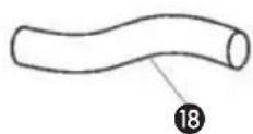

natural_image
Grid pattern with a numbered label pointing to a specific cell (no text or symbols present)
-
LES BRUKSINSTRUKSENE F∅RST.
-
VED TVIL, TA KONTAKT MED FORHANDLEREN.
N
Kjære kunde

AdVArSel
× Laveste innstilling.
natural_image
Diagram of a portable air conditioner unit with airflow arrows indicating internal cooling zones (no text or symbols)
d luftfilter
Plasser filter i holderen.
natural_image
Line drawing of a large industrial air conditioner unit with cooling fans and ventilation slots (no text or symbols)i OPPBeVAring


natural_image
Isometric line drawing of a cylindrical object with internal parallel grooves (no text or symbols)
natural_image
Isometric line drawing of a rectangular panel with a circular cutout and numbered annotations (15, 16), no text or symbols present.
natural_image
Two mechanical components with numbered callouts (13 and 14), no visible text or symbols

natural_image
Grid pattern with a numbered label pointing to a specific cell (no text or symbols present)
natural_image
Four-panel diagram showing mechanical or electrical assembly steps with no visible text, numbers, or symbols.flowchart
graph TD
    A[" fan installation"] --> B[" grid array installation "]
    B --> C[" grid array installation "]
    C --> D[" grid array installation "]
    D --> E[" grid array installation "]
    E --> F[" grid array installation "]
    F --> G[" grid array installation "]
    G --> H[" grid array installation "]
    H --> I[" grid array installation "]
    I --> J[" grid array installation "]
    J --> K[" grid array installation "]
    K --> L[" grid array installation "]
    L --> M[" grid array installation "]
    M --> N[" grid array installation "]
    N --> O[" grid array installation "]
    O --> P[" grid array installation "]
    P --> Q[" grid array installation "]
    Q --> R[" grid array installation "]
    R --> S[" grid array installation "]
    S --> T[" grid array installation "]
    T --> U[" grid array installation "]
    U --> V[" grid array installation "]
    V --> W[" grid array installation "]
    W --> X[" grid array installation "]
    X --> Y[" grid array installation "]
    Y --> Z[" grid array installation "]
    Z --> AA[" grid array installation "]
    AA --> AB[" grid array installation "]
    AB --> AC[" grid array installation "]
    AC --> AD[" grid array installation "]
    AD --> AE[" grid array installation "]
    AE --> AF[" grid array installation "]
    AF --> AG[" grid array installation "]
    AG --> AH[" grid array installation "]
    AH --> AI[" grid array installation "]
    AI --> AJ[" grid array installation "]
    AJ --> AK[" grid array installation "]
    AK --> AL[" grid array installation "]
    AL --> AM[" grid array installation "]
    AM --> AN[" grid array installation "]
    AN --> AO[" grid array installation "]
    AO --> AP[" grid array installation "]
    AP --> AQ[" grid array installation "]
    AQ --> AR[" grid array installation "]
    AR --> AS[" grid array installation "]
    AS --> AT[" grid array installation "]
    AT --> AU[" grid array installation "]
    AU --> AV[" grid array installation "]
    AV --> AW[" grid array installation "]
    AW --> AX[" grid array installation "]
    AX --> AY[" grid array installation "]

natural_image
Diagram of a portable air conditioner unit with airflow arrows indicating internal structure (no text or symbols)
d luchtfilter
natural_image
Line drawing of a large industrial air conditioner unit with fan and control panel (no text or symbols)OntVOchtigen


natural_image
Isometric line drawing of a cylindrical object with internal parallel grooves (no text or symbols)
natural_image
Isometric line drawing of a rectangular panel with a circular cutout and numbered annotations (15, 16), no text or symbols present.
natural_image
Two mechanical components with numbered callouts (13 and 14), no visible text or symbols

natural_image
Grid pattern with a numbered label pointing to a specific cell (no text or symbols present)
- PRZED PIERWSZYM UŻYCIEM PRZECZYTAĆ INSTRUKCJE, OBSIUGI.
- W RAZIE WATPLIWOŚCI SKONTAKTOWAĆ SIE, Z DEALEREM.
Szanowni Państwo,

Uwaga!
natural_image
Diagram of a portable air conditioner unit with airflow arrows indicating internal cooling zones (no text or labels)
UWAGA!
natural_image
Line drawing of a large industrial air conditioner unit with cooling fans and ventilation slots (no text or symbols)i pRzechOwywanie


natural_image
Isometric line drawing of a cylindrical object with internal grooves and a labeled point (12), no text or symbols present.
natural_image
Isometric line drawing of a rectangular panel with a circular cutout and numbered annotations (15, 16) pointing to its edges.
natural_image
Two mechanical components with numbered callouts (13 and 14), no visible text or symbols.

natural_image
Grid pattern with a numbered label pointing to a specific cell (no text or symbols present)
- BÖRJA MED ATT LÄSA IGENOM ANVISNINGARNA FÖR ANVÄNDNING.
- KONTAKTA FÖRSÄLJAREN OM DET ÄR NÅGOT DU UNDRAR ÖVER.
Bäste kund,
natural_image
Four-panel diagram showing mechanical or electrical component arrangements, with no visible text, numbers, or symbols.
VArning
flowchart
graph TD
    A["Fan with grid"] --> B["Grid of panels"]
    B --> C["Grid of panels on battery unit"]
    C --> D["Grid of panels on battery unit"]
    D --> E["Grid of panels on battery unit"]

natural_image
Diagram of a portable air conditioner unit with airflow arrows indicating internal structure (no text or symbols)
d luftfilter
natural_image
Line drawing of a large industrial air conditioner unit with cooling fans and ventilation slots (no text or symbols)i förVAring


natural_image
Isometric line drawing of a cylindrical object with internal grooves and a labeled point (12), no text or symbols present.
natural_image
Isometric line drawing of a rectangular panel with a circular cutout and numbered annotations (15, 16) pointing to its edges.
natural_image
Two mechanical components with numbered callouts (13 and 14), no visible text or symbols

natural_image
Grid pattern with a numbered label pointing to a specific cell (no text or symbols present)
- NAJPREJ PREBERITE NAVODILA ZA UPORABO.
- V PRIMERU NEGOTOVOSTI POKLIČITE SERVIS
SLO
Spoštovani,

OPOZORILO

VEDITE
Kompresor prične delovati šele 3 minute po (ponovnem) vklopu naprave. Naprava preneha s hlajenjem, kadar je temperatura prostora pod nastavljeno. Ventilator bo kljub temu deloval na nastavljeni vrednosti.
Ko se temperatura prostora poviša nad nastavljeno, naprava nadaljuje s hlajenjem.
NAČIN MIROVANJA
natural_image
Diagram of a portable air conditioner unit with airflow arrows indicating internal structure (no text or symbols)
E PRETOK ZRAKA
Za spreminjanje kota izpuha zraka preko rešetk, premikajte rešetke.
F PRAZNJENJE VODNEGA REZERVOARJA
natural_image
Line drawing of a large industrial air conditioner unit with cooling fans and ventilation slots (no text or labels)I HRANJENJE NAPRAVE
1 Izpraznite vodni rezervoar (glej poglavje F)
2 Očistite ali zamenjajte filter (glej poglavje D)
3 Za 2 ur vključite le ventilator, da se naprava popolnoma osuši.
4 Kabel pospravite kot je prikazano. Napravo zavarujte pred prahom in jo shranite v suhem prostoru.
J ODPRAVLJANJE TEŽAV


natural_image
Isometric line drawing of a cylindrical object with internal grooves and a labeled point (12), no text or symbols present.
natural_image
Isometric line drawing of a rectangular panel with a circular cutout and numbered annotations (15, 16), no text or symbols present.
natural_image
Two mechanical components with numbered callouts (13 and 14), no visible text or symbols

natural_image
Grid pattern with a numbered label pointing to a specific cell (no text or symbols present)
1 ÖNCE KULLANMA TALİMATLARINI OKUYUN.
2 FIÜPHE DURUMUNDA BAYIİNİZLE TEMASA GEÇİN.
Sayın Bay/Bayan,
natural_image
Four-panel diagram showing mechanical or electrical assembly steps with no visible text, numbers, or symbols.
UYARI

NOT!
natural_image
Diagram of a portable air conditioner unit with airflow arrows indicating internal cooling zones (no text or labels)
natural_image
Line drawing of a large industrial air conditioner unit with cooling fans and wheels (no text or symbols)I DEPOLAMA


- 1
- SicurezzA
- I AUFBEWAHRUNG
- d luftfilter
- i OPBeVAring
- B mOntAJe
- Atención
- i rAngement
- VArOituS
- i SÄiIYtYS
- A SAFETY INSTRUCTIONS
- IMPORTANT
- AttentiOn!
- B inStAllAtiOn
- WARning
- C OPerAtiOn
- cOOling
- Air circulAtiOn
- nOte!
- SleeP mOde
- remOte cOntrOl
- d Air filter
- e Air flow
- f emPtY internAI WAter cOntAiner
- dehumidificAtiOn
- g cConnectiOn tO A PermAnent drAin
- h mAintenAnce
- WARning!
- i StOrAge
- J TROUBLE SHOOTING
- k guArAntee cOnditiOnS
- L TECHNICAL DATA
- COMPONENTI PRINCIPALI
- B inStAllAziOne del climAtizzAtOre
- AVVertenzA
- OSSerVAziOne!
- J GUIDA ALLA RICERCA GUASTI
- AdVArSel
- i OPPBeVAring
- d luchtfilter
- OntVOchtigen
- Uwaga!
- i pRzechOwywanie
- VArning
- i förVAring
- OPOZORILO
- VEDITE
- NAČIN MIROVANJA
- E PRETOK ZRAKA
- F PRAZNJENJE VODNEGA REZERVOARJA
- I HRANJENJE NAPRAVE
- J ODPRAVLJANJE TEŽAV
- UYARI
- NOT!
- I DEPOLAMA
Brand : ZIBRO
Model : P 24
Category : Air Conditioning