PH 233 - Air Conditioning ZIBRO - Free user manual and instructions
Find the device manual for free PH 233 ZIBRO in PDF.

User questions about PH 233 ZIBRO
0 question about this device. Answer the ones you know or ask your own.
Ask a new question about this device
Download the instructions for your Air Conditioning in PDF format for free! Find your manual PH 233 - ZIBRO and take your electronic device back in hand. On this page are published all the documents necessary for the use of your device. PH 233 by ZIBRO.
USER MANUAL PH 233 ZIBRO
natural_image
Exterior view of a modern stainless steel water heater (no visible text or symbols)guarantee
2
YEARS
| D | GEBRAUCHSANWEISUNG | 4 |
| E | INSTRUCCIONES DE USO | 22 |
| F | MANUEL D'UTILISATION | 38 |
| GB | OPERATING MANUAL | 54 |
| I | ISTRUZIONI D'USO | 70 |
| NL | GEBRUIKSAANWIJZING | 88 |
| TR | KULLANIM KILAVUZU | 104 |
DALLGEMEINE SICHERHEIT
For safety reasons, please read this manual carefully before operating. Persons who are not familiar with this manual must not use this air conditioner. We strongly recommend keeping this manual in a safe place for future reference.
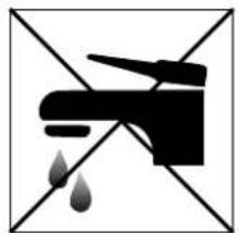
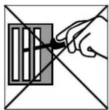
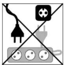
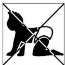
| A. Do not use a damaged cable. | G. Do not immerse in water. |
| B. Do not clamp or bend the cable. | H. Do not spill. |
| C. Do not place unevenly. | I. Do not insert anything. |
| D. Do not place in front of an open window. | J. Do not use an extension cord. |
| E. Do not bring in contact with chemicals. | K. Keep out of the reach of children. |
| F. Do not place near a heat source. | L. Do not repair. |

natural_image
Abstract black-and-white geometric pattern with diagonal lines and a central emblem (no text or symbols)A
natural_image
Abstract geometric line drawing with intersecting lines and a central symbol (no text or labels)B
text_image
>10C

natural_image
Simple line drawing of a window frame with diagonal lines and a shaded bottom panel (no text or symbols)D

text_image
OILE

natural_image
Simple line drawing of a campfire with no text or symbolsF
natural_image
Black and white pictogram of a faucet with water droplets falling, no text or symbols presentG

natural_image
Simple line drawing of a bottle pouring liquid into a container, crossed by two diagonal lines (no text or symbols)H
natural_image
Hand holding a pen over a grid-patterned object, intersected by two diagonal lines (no text or symbols)|
natural_image
Pure electrical circuit lines without any symbolsJ
natural_image
Silhouette of a dog and a cat crossed out by diagonal lines (no text or symbols)K
natural_image
Abstract geometric pattern with black and gray shapes intersected by diagonal lines (no text or symbols)L
SICUREZZA
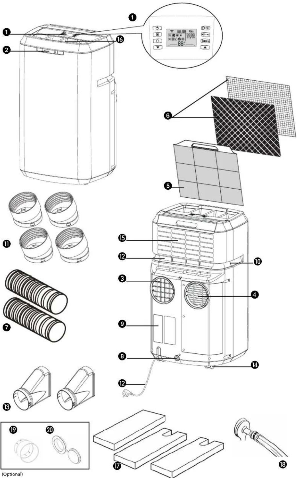
① Remote control
② Control panel
③ Air outlet
4 Air inlet
⑤ Filter holder
6 Air filters (activated carbon + Bacterio-static 3M™ HAF filter)
⑦ Air duct (2x)
8 Water drain
⑨ Drainage point (PH227 + PH233)
10 Handles
⑪ Hose connector (4x)
⑫ Electricity cable
⑬ Hose adapter (2x)
14 Wheels
15 Air inlet for air to be cooled/filtered
16 Air exhaust for air to be cooled/filtered
17 Foam component
18 Water hose (PH227 + PH233)
19 Hose connector
20 Hose adapter
-
FIRST READ THE INSTRUCTIONS.
-
IF YOU HAVE ANY DOUBTS, CONSULT YOUR DEALER.
GB
Dear Sir, Madam,
Congratulations on the purchase of your Zibro air conditioner. This air conditioner has five functions in addition to cooling the air, namely heating (for PH 227 + PH 233 only), air dehumidification, circulation and filtration as well as purification of air by it's unique sterionizer bi-polar ionisation. The mobile air conditioner is extremely easy to operate and move. You have acquired a high quality product that will provide you with many years of pleasure, on condition that you use it responsibly. Reading these instructions for use before operating your air conditioner will optimise its life span. We wish you coolness and comfort with your Zibro air conditioner.
Yours sincerely,
PVG International B.V.
Customer service department
A SAFETY REGULATIONS

IMPORTANT
- The installation must be completely in accordance with local regulations, ordinances and standards.
- The device is suitable exclusively for use in dry places, indoors.
- Check the mains voltage. This device is suitable exclusively for earthed sockets – connection voltage 230 Volt/ 50 Hz.
- The device MUST always have an earthed connection. You may absolutely not connect the device if the power supply is not earthed.
- The plug must always be easily accessible when the device is connected.
- Read these instructions carefully and follow the directions.
Before connecting the device, check that:
- The connection voltage corresponds to that on the type plate.
- The socket and power supply are suitable for the device.
- The plug on the cable fits the socket.
- The device is on a stable and flat surface.
Have the electrical installation checked by a recognised expert if you are not sure that everything is in order.
- The airconditioner is a safe device, manufactured in accordance with CE safety standards. Nevertheless, as with every electrical device, exercise caution when using it.
- Never cover the air inlets and outlets.
- Empty the water reservoir through the water drain ⑧ before moving it.
- Never allow the device to come into contact with chemicals.
- Do not insert objects into the openings of the device.
- Never allow the device to come into contact with water. Do not spray the device with water or submerge it as this may cause a short circuit.
- Always take the plug out of the socket before cleaning or replacing the device or a part of the device.
- NEVER connect the device with the aid of an extension cable. If a suitable, earthed socket is not available, have one fitted by a recognised electrician.
- Always consider the safety of children in the vicinity of this device, as with every electrical device.
- Always have any repairs – beyond regular maintenance – carried out by a recognised service engineer. Failure to do so may lead to invalidation of the guarantee.
- Always take the plug out of the socket when the device is not in use.
- A damaged electricity cable may only be replaced by the supplier or an authorised person/service point.
- This appliance is not intended for use by persons (including children) with reduced physical, sensory or mental capabilities, or lack of experience and knowledge, unless they have been given supervision or instruction concerning use of the appliance by a person responsible for their safety.

- Children should be supervised to ensure that they do not play with the appliance.
ATTENTION!
- Never use the device with a damaged cable or plug. Never allow the cable to be pinched off or come into contact with sharp edges.
- Never seal the room in which the device is to be used completely airtight (also not when using two air hoses). This will prevent the occurrence of underpressure in this room. Negative pressure can disrupt the safe operation of geysers, extractor fans, ovens, etc.
- Failure to follow the instructions may lead to invalidation of the guarantee on the device.
• Always lift the device with two people.
B INSTALLATION
natural_image
Diagram of an air conditioner unit with heat distribution panels and ventilation slots (no text or labels)
WARNING
Before using the air conditioner it should be left in an upright position for at least 2 hours.
This unit is portable and can easily be moved from one room to another. In doing so keep this in mind:
1 Ensure that the unit is positioned upright and on a level surface.
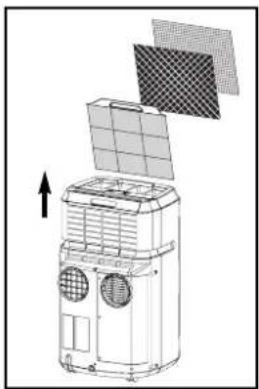
2 Place the loose filters in the filter holder.
• Take the filter holder ⑤ out of the air conditioner
- Place the active carbon filter (black) and Bacterio-static 3M ^TM HAF filter in the filter holder 5.
- Place the filter holder back in the air conditioner.
3 Do not operate the unit inside the bathroom, shower, or in any other very humid environment.
4 Please keep a distance of 50 cm between the unit and the wall or other objects to ensure proper air circulation.
5 Insert both ends of the air exhaust hose ⑦ in the round connectors ⑪. Fasten the connectors by turning them clockwise onto the hose.
6 Insert round connector ⑪ in the backside of the unit ③. Fasten the other connector ⑪ to the window air outlet ⑬.
7 Attach the hose connector ⑪ to air outlet ③ at the back of the unit. Lead the hose adapter ⑬ outside and close the gap with the foam components supplied. These may have to be cut to size.
GB

natural_image
Line drawing of a portable air purifier with handle and ventilation duct (no text or symbols)
natural_image
Line drawing of a portable air conditioner unit next to a door (no text or symbols)Models are fitted with the EVS (Effective Ventilation System) as standard. The second hose ⑦ must be attached in order to utilise this option. Attach the hose connectors ⑪ and the hose adapter as described above.

ATTENTION!
The device can be used with 1 or with 2 hoses. If the device is used with 2 hoses, it may fall into a different Energy Efficiency Class. Refer to the technical specifications in this manual. However, using a second hose as described can have a positive effect on the energy balance in the room where the device is placed. Using the unit with the 2 hoses will ensure that the unit cools in the most effective and quickest way.
If use of the second hose is not possible or desired, then connecting a single hose to the air outlet ④ at the back of the airconditioner will suffice for the cooling mode.
8 Keep windows and outside doors closed as much as possible in order to prevent the inflow of exterior air. The air that is intended to enter the room (specifically during the use of a single hose) in order to allow the airconditioner to function correctly must always be as cool as possible. Leading this air through a passage or adjacent room increases the comfort level.

TIP!
When the device is in use in the cooling mode with two air hoses, it is prudent to lead the hoses to the outside (e.g. through a window) on the shadow side of the building. This will cool the air that is sucked in as much as possible. In the heating mode, the air hoses can be led out of the building on the sunny side. The expelled air is then as warm as possible.
IMPORTANT
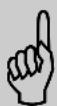
The flexible air exhaust hose(s) can be stretched to a length of approximately 1200 mm. The length of these hose(s) was calculated on the basis of the capacity of the device. The use of other hoses or extensions may cause faults in the device. The air must be able to flow unhindered. If this is not possible this may lead to overheating or water condensation in the air exhaust hose ⑦.
This is why you must ensure that there are no kinks or sharp corners in the air hose(s). To obtain an optimum result, the air hoses must be kept shorter than 1 metre while the airconditioner is in use.
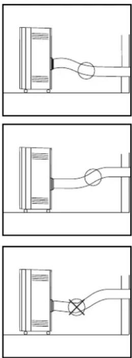
SINGLE DUCT USE.
When models are used as single duct the "single duct back cover plate" (see item A in picture) must be taken off by unscrewing the 3 screws 1, 2 and 3.
The only duct now to be used is the exhaust hose. The exhaust hose must be mounted to opening B (see picture).
natural_image
Three technical line drawings showing fluid or piping connections between containers and a pipe (no text or symbols)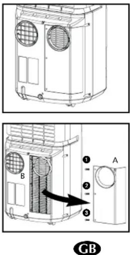
text_image
Technical diagram showing two views of a heating unit with labeled components and an arrow indicating direction.- Avoid the remote control from getting wet. Remove it from the unit when condensation can occur.

text_image
On/off Fan speed Function selector switch Down 88:88 88:88 On Off 88°F LCD display Timer/Clock Low noise Sterionizer1/2 Up
text_image
Signal indicator Clock Sterionizer™ function indicator Timer setting indicator Timer on/off Ventilator speed indicator Function indicator 88:88 88:88 On Off 88°F Celsius / Fahrenheit control light Temperature setting indicator
text_image
Emergency on/off switch Low noise indicator Sterionizer™ function indicator LED lamps on/off switch Multi colour light indicatorSymbols:
Automatic
Cooling
Dehumidifying
Circulating air
Heating (only on PH 227 + PH 233)
High ventilator speed
Average ventilator speed
* Low ventilator speed

ATTENTION!
Without the remote control, the air-conditioner can be operated by using the ⏻ button on the front of the device. In this event however, only the automatic function ✗ can be used.

natural_image
Line drawing of three mechanical components: a cylindrical part, a rectangular block with internal connectors, and a flat plate (no text or symbols)PLACING BATTERIES IN THE REMOTE CONTROL
Remove the battery cover by pressing the lips in and then pulling the cover toward you. Place the new batteries as indicated (pay attention to the plus- (+) and minus poles (-). Now replace the battery cover.

NOTE!
Use 2 AAA (1.5 Volt) batteries. Do not use rechargeable batteries.
Replace batteries with new batteries of the same type when the display becomes fuzzy or the signal deteriorates.
1 Push the plug into the socket.
2 By pressing both ▲ and ▼ set buttons at the same time, the display will toggle between Celsius and Fahrenheit.
3 The following functions can be selected with the mode button on the remote control.
✗ Automatic regulation of ventilator speed
Cooling;
Dehumidifying;
Circulating;
Heating (PH227 + PH233).
AUTOMATIC
In the automatic mode ✗the device will automatically cool, dehumidify or heat depending on the ambient temperature. When the temperature in the room changes, the mode changes automatically in order to maintain the by factory set temperature as accurately as possible. The ventilator speed also adjusts automatically. The colour of the transparent 12 -ring around the button on the front of the device ②will change depending on the mode.
Factory settings automatic mode
For models without heat function
When the room temperature is 25^ C or above, the appliance will start the cooling mode. When the room temperature below 25^ C, the appliance will start the dehumidifying mode. In this function the air will get cooler.
For models with heat function
When the room temperature is 25^ C or above, the appliance will start the cooling mode. When the room temperature is between 18^ C and 24^ C, the appliance will start the dehumidifying mode. In this function the air will get cooler. When the room temperature is below 18^ C, the appliance will start the heating mode.
Each mode is determined by the temperature only, not the humidity.
text_image
Dehumidifying mode (yellow) PH227 + PH233STERIONIZER™ FUNCTION
Press Sterionizer ^™ function to start the function and press again to stop it. Positive and negative ions are generated in every operating mode.
LOW NOISE BUTTON
During unit operation. Press low noise button, unit operates at low noise. Press the button again to cancel the low noise setting and return to the previous setting. In low noise mode the unit will provide less cooling or heating capacity.
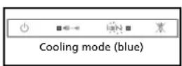
COOLING
When the cooling mode is activated, the transparent 12 -ring around the button on the front of the device ② emits a BLUE light.
The following settings are possible in the cooling mode:
- The ventilator speed can be adjusted by pressing the -button
✗ Automatic regulation of ventilator speed
High
Average
* Low
- The temperature can be set between 16^ and 32^ (PH227 + PH233: 16^ - 27^ ) by pressing the ▲ and ▼ buttons. The display on the remote control shows the set temperature.

Whether the desired temperature can actually be reached depends on the ambient conditions. The room temperature remaining above the set temperature is normal.
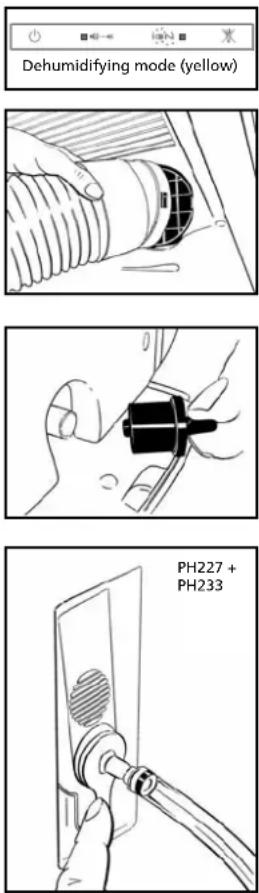
DEHUMIDIFICATION
When the dehumidification mode is activated, the transparent ^1/2 - ring around the button on the front of the device ② turns YELLOW.
The dehumidification function can be used in different ways.
1) All models:
Only connect the air exhaust hose ⑦ to the air outlet ③ and lead it outside, as when using the device in the cooling function with a single hose. Place the hose in such a way that the hot air is expelled outside. The device will then dehumidify the air in the room and remove excess moisture through the air hose.
2) All models:
Do not connect the air supply nor the air exhaust hose. Remove the rubber plug from the water drain ⑧ and ensure that the water can run out safely (e.g. through a drain hole in the floor). You can also connect a water hose to the water drain (see chapter F).
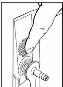
3) PH227 + PH233:
Connect the supplied water hose ⑱ to the plug that fits into the water drain. Lead the other end to a drain or sink and insert the plug into the water drain ⑧. Do not connect both the air supply ⑦ and the air exhaust hose. The condensed
GB
natural_image
Line drawing of a hand inserting a mechanical component into a device (no text or symbols)water will be removed through the hose. The maximum rise may be 1.5 m from the floor on which the device is standing. Exceeding this distance may damage the machine or cause leaks.
During the dehumidification, the ventilator speed can not be adjusted when room temperature is below 25^ C. Below 25^ C the fan speed is fixed to "low".

ATTENTION!
In the automatic mode, the condensed moisture is always removed through the air exhaust hose. Removing the rubber plug from the water drain will allow the water to drain out at this point. The water drain can not be used.
When the device is not being used in the (manual) dehumidification mode, the plug must be removed from the water drain ⑧.
CIRCULATING
When the air circulation mode is switched on, the transparent 12 ring around the button on the front of the device ②emits GREEN light. In this mode, the air is circulated and filtered but not cooled, dehumidified or heated. In this mode, only the ventilator speed can be adjusted by pressing the ②button:

✗ Automatic regulation of ventilator speed
High
Medium
Low

HEATING MODE (PH227 + PH233)
When the heating mode is activated, the transparent 12 ring around the button on the front of the device ②emits a RED light.
The heating mode of this device works on the heat pump principle. This makes it more efficient than a normal electric heater. The heating mode can only be activated when the ambient temperature is below 27^ C. Depending on the outside temperature, the device will stop heating regularly in order to thaw ice that has accumulated. The lower the outside temperature, the more frequently this will occur. In this mode, the desired temperature can be set between 16 and 27^ C.
When the device is in heating mode, both air hoses must be connected and led outside.

text_image
27°C 16°C Cooling Dehumidify Heat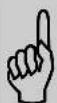
NOTE!
- To prevent damage to the device, changing from the cooling or dehumidification mode to the heating mode (or the reverse) takes two to three minutes (PH227 + PH233).
- When Sterionizer ^TM function is switched on, positive and negative ions are generated in every operating mode.
GB
You can use the timer function to set in advance when the airconditioner is to
switch on or off.
Switching off
The timer OFF function can be set when the airconditioner is switched on:
- Press button
- Set the number of hours desired (1-12) with the aid of ▲ and ▼
- Press to save
Switching on
Default temperature setting is 24°C.
The timer ON function can be set when the airconditioner is switched off (stand-by):
- Select the desired mode and temperature
- Press button
- Set the number of hours desired (1-12) with the aid of ▲ and ▼
- Press to save
You can delete the set timer function by pressing the button on the remote control.
When the set time is at "00", the timer is switched off. When the Timer function has been set the blue light in the button on the front of the device will switch on.
- Press Timer/Clock button for 3 seconds. Change the time by pressing the ▲ and ▼ -button. When the desired time has been set, press the Timer/Clock button for 3 seconds again in order to save the setting. In every holding second LCD clock display changes setting by 1 minute interval.
- Press ▲ or ▼ and holding more than 1 second, the LCD clock display changes setting by 30 minutes interval.

TIP!
The light of the display fades when the remote control has not been used for some time. This is reactivated when you touch any button.

ATTENTION
Avoid the remote control from getting wet. Remove it from the unit when condensation can occur.
LAMPS ON/OFF SWITCH
Switch to on/off lights on control panel on front of unit. When lights are switched to Off, the alarm function of the lights is still maintained.
D AIR FILTER
This airconditioner is fitted with a 3-layer filter to purify the circulating air. The airconditioners are supplied with a separately packed Bacterio-static 3M ^™ HAF filter and activated carbon filter. These filters must be placed in accordance with the instructions before the airconditioner is used.
GB
natural_image
Simple diagram showing a sun icon emitting sound waves to two speakers (no text or symbols)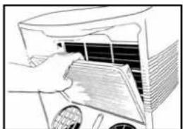
natural_image
Illustration of a hand opening a car air conditioner cover (no text or symbols visible)
natural_image
Diagram of a 3D printer with grid layout and three patterned panels (no text or symbols)1 Wire mesh filter to remove coarse dust particles.
2 Bacterio-static 3M ^™ HAF filter to remove particles from the air such as pollen, animal dander and dust.
3 Activated carbon filter to remove odours.
The mesh filter is part of the filter holder. The filter holder can be opened. The activated carbon filter and the Bacterio-static 3M™ HAF filter can be removed.
1 The mesh filter must be cleaned regularly with a vacuum cleaner in order to prevent blockage of the air flow.
2 We recommend replacing this electrostatically charged Bacterio-static 3M HAF filter every three months.
new filter
f filter
3 If it has become dusty, the activated carbon filter can be cleaned with a vacuum cleaner, but it must be replaced simultaneously with the Bacterio-static 3M ^™ HAF filter.
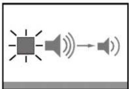
Excessive dust, building work, pets, the presence of smoke and frequent use of the device affect the lifespan of the Bacterio-static 3M ^™ HAF filter. A signal is given after approximately 650 hours of operation in order to prevent you from forgetting to replace the filter: The Low Sound light on the front of the device is blinking. Take the following action:
1 First switch the device off and pull the plug out of the socket.
2 Replace the old filters with new, original filters that are available from your dealer;
- Remove the filter holder ⑤ from the airconditioner
-
Open the filter holder ⑤, take the filter clamp off the filter holder and remove the old filters. Place the new activated carbon filter (black) and 3M^TM HAF filter (white) in the filter holder ⑤.
-
Fit the filter clamp back onto the holder.
- Put the filter holder ⑤ back into the airconditioner.
3 Press the LED lamps on/off switch on the front of the device (approximately 4 seconds), until it beeps.
4 The indicator light is switched off.
5 The old filters are not chemical waste and may be thrown away in the normal rubbish container (not biological waste).

natural_image
Pure electrical circuit lines without any symbols
NOTES!
- Never use the airconditioner without the mesh filter!
- Using the device without the activated carbon filter and/or 3M ^TM HAF filter will not damage the device. In this case, particles that may be detrimental to health are not removed.
- Filter packages are available at your dealer.
- Only use suitable Zibro filters. This will prevent any damage to your airconditioner. Using other than the original filters is entirely at the risk of the consumer. This may have a negative effect on the operation of the device and may result in damage. The device may also leak water subsequent to the formation of ice.

natural_image
Line drawing of a hand holding a mechanical component, no text or symbols presentE EMPTYING THE WATER RESERVOIR
In extreme circumstances it may be necessary to empty the internal water reservoir. When the water reservoir is full, the transparent 12 -ring around the button on the front of the device ② flashes RED. To empty the water reservoir, take the following action:
1 Do not move the device. This may cause water leakage.
2 First switch the device off and remove the plug from the socket.
3 Place a pan or container on the floor under the water drain ⑧.
4 Remove the rubber plug from the water drain 8 and let the water drain out (± 1 litre).
5 Insert the rubber plug back into the water drain ⑧, push the plug into the socket and switch the device on. The warning signal should now be off.
NOTE!
Under normal conditions, the condensed water in the airconditioner is removed via the air outlet hose.
F CONNECTION TO A PERMANENT DRAIN
1 First switch the device off and pull the plug out of the socket.
2 Place a pan or container on the ground under the water drain ⑧ in order to catch any remnant water.
3 Remove the rubber plug from the water drain 8.
4 Slide a water drain hose over the water drain 8.
GB
5 Lead the other end of the water drain hose to suitable place (drain/sink). Ensure that the drain hose is not twisted or kinked.

ATTENTION!
The hose must be descending along its entire length.
G MAINTENANCE

ATTENTION!
First switch the device off and pull the plug out of the socket before you clean the device or filter or when you replace the filters.
Use a soft, damp cloth for the regular cleaning of the exterior of the device. Never use aggressive cleaning agents, solvents, benzene or abrasives. Refer to chapter D "Air Filter" for filter maintenance.

NOTE!
Never use the device without the mesh filter.
H STORAGE
1 Empty the water reservoir (see chapter E).
2 Clean the mesh filter (see also chapter D).
- Remove the activated carbon filter and the Bacterio-static 3M ^™ HAF filter at the end of the season and only insert the new filters at the start of the new season. The old filters are not chemical waste and may be thrown away in the waste container (not biological waste).
- New filters are available at your dealer.
3 Switch the device to air circulation mode for several hours. This will completely dry out the interior.
4 Protect against dust and store in a dry place that is not accessible to children.
I PROBLEMS AND SOLUTIONS
| Problem Cause Solution | ||
| The device does not work and the transparent 1/2 - ring around the button on the front of the device flashes RED. | The internal water reservoir is full. | Empty the internal water reservoir (see chapter E). |
| The device does not work and the left hand side of the transparent 1/2 - ring around the button on the front of the device flashes BLUE. | The room temperature sensor is defective. | Consult your dealer. |
| The device does not work and the right hand side of the transparent 1/2 - ring around the button on the front flashes BLUE. | The temperature sensor of the heat exchanger is disrupted or has short circuited. | Consult your dealer. |
| The device does not work. No power supply. | Insert the plug into a socket that is live. | |
| The device works insufficiently. | Standing in direct sunlight. | Move the device into the shade. |
| Windows or doors are open or there are a large number of people or heat sources in the room. | Close windows and/or doors or place an extra airconditioner. | |
| The filter is dirty. | Clean the filter or replace it (see chapter D). | |
| Air inlet or exhaust is blocked. | Remove the blockage. | |
| The device makes a great deal of noise. | The device is standing on an uneven surface. | Place the device on an even surface (less vibration). |
| The compressor does not work. | The overheating safety feature has been activated. | Wait 30 minutes until the temperature has dropped and then switch it on again. Clean the filter (if necessary). |
| The remote control does not respond. | The distance is too big. The batteries are empty. | Replace the batteries/Step closer to unit. |
Never attempt to disassemble or repair the device. Inexpert repairs invalidate the guarantee and can endanger the users of the device.
J GUARANTEE CONDITIONS
We provide a 24-month warranty on the airconditioner from the date of purchase.
All material and production faults will be repaired free of charge within this period. The following rules apply:
- We expressly reject all other claims for damage compensation, including consequent damage.
- Repairs or replacements carried out during the guarantee period do not result in an extension of the guarantee.
- The guarantee is invalidated when changes are made, non original parts are fitted or repairs are conducted by third parties.
- Parts that are subject to normal wear, such as the filter, fall outside the guarantee.
- The guarantee is only valid if you submit the original, dated and unaltered purchase invoice.
- The guarantee does not apply to damage caused by actions that deviate from the instructions or negligence.
- The shipping costs of the airconditioner or parts and the related risk are always borne by the purchaser.
- Damage, caused by not using suitable Zibro filters falls outside the guarantee.
To prevent unnecessary costs, we recommend that you always first read the instructions carefully. If this does not provide a solution, take the airconditioner to your dealer for repairs.
K TECHNICAL SPECIFICATIONS
Use indicatively, subject to change.
| Model | P 227 PH 227 P 229 PH 233 | ||||
| Cooling capacity* W 2700 | 2700 | 2900 | 3300 | ||
| EE Class | A | A | A | B | |
| EER* | 2,62 | 2,62 | 2,7 | 2,5 | |
| Heating capacity* | W | 2700 | 3150 | ||
| Heating performance | C | C | |||
| COP* | 2,61 | 2,61 | |||
| Power consumption | kW | 1,03 | 1,03 | 1,07 | 1,32 |
| Current nom. | A | 5 | 5 | 4,2 | 4,8 |
| Mains | V/Hz/Ph | 230 / 50 / 1 | 230 / 50 / 1 | 230 / 50 / 1 | 230 / 50 / 1 |
| Air delivery max. | m3/h | 300 | 300 | 300 | 280 |
| Dehumidification max. ** | L/24h | 26 | 26 | 35 | 40 |
| For rooms up to | m3 | 65- 90 | 65 - 90 | 70 - 95 | 80 - 105 |
| Compressor type | rotary | rotary | rotary | rotary | |
| Refrigerant | type/gr | R-410A / 650 | R-410A / 650 | R-410A / 560 | R-410A / 630 |
| Thermostatic range | °C 16 - 32 | 16 - 27 | 16 - 32 | 16 - 27 | |
| Fan speed positions | 3 | 3 | 3 | 3 | |
| Max. sound pressure level | dB (A) | 40-51 | 40-51 | 37-52 | 37-49 |
| Dimensions (w x h x d) | mm | 436 x 745 x 390 | 436 x 745 x 390 | 440 x 745 x 390 | 440 x 745 x 390 |
| Weight | kg | 30 | 31 | 29 | 33 |
| Unit protection | IP 20 | IP 20 | IP 20 | IP 20 | |
| Remote control | Yes | Yes | Yes | Yes | |
| Bacterio-static 3MTM HAF filter + screen filter | Yes | Yes | Yes | Yes | |
| Active carbon filter | Yes | Yes | Yes | Yes | |
| SterionizerTM | - & - Ions / soc | 1,0 * 10° | 1,0 * 10° | 1,0 * 10° | 1,0 * 10° |
| EVS*** | Yes | Yes | Yes | Yes | |
| Fuse rating | 250V, T3,15A | 250V, T3,15A | 250V, T3,15A | 250V, T3,15A | |
* Conform EN 14511-2007, based on single duct use
** Moisture removal at 27°C, 60% RH
*** See chapter B
Environmental information: This equipment contains fluorinated greenhouse gases covered by the Kyoto Protocol. It should only be serviced or dismantled by professional trained personnel.
This equipment contains R410A refrigerant in the amount as stated in the table above. Do not vent R410A into atmosphere: R410A, is a fluorinated greenhouse gas with a Global Warming Potential (GWP) = 1975.
Waste electrical products should not be disposed with household waste. Please recycle where facilities exist. Check with your local authority or retailer for recycling advice.

text_image
zibro www.zibro.comD Benötigen Sie weitere Informationen oder treten Probleme auf, besuchen Sie bitte unsere Website www.zibro.com, oder setzen Sie sich mit unserem Kundendienst in Verbindung (Telefonnummer auf www.zibro.com).
For alle yderligere oplysninger eller ved eventuelle problemer med apparatet henvises til www.zibro.com eller det lokale Kundecenter (telefonnumre findes i www.zibro.com).
Si necesita información o si tiene algún problema, visite nuestra página Web www.zibro.com, o póngase en contacto con el servicio cliente (hallará el número de teléfono en www.zibro.com).
⑤ Si vous souhaitez obtenir des informations supplémentaires ou si vous rencontrez un problème, rendez-vous sur notre site Web (www.zibro.com) ou contactez le notre service client (vous trouverez l'adresse et numéro de téléphone sur www.zibro.com).
Jos haluat huoltoapua, lisätietoja tai laitteen kanssa tulee ongelmia, tutustu verkkosivustoon osoitteessa www.zibro.com tai kysy neuova PVG kuluttajapalvelukeskuksesta (www.zibro.com).
(6) If you need information or if you have a problem, please visit the our website (www.zibro.com) or contact our sales support (you find its phone number on www.zibro.com)
Per informazioni e in caso di problemi, visitate il sito Web www.zibro.com oppure contattate il Centro Assistenza Clienti (per conoscere il numero di telefono, consultate www.zibro.com).
Hvis du trenger informasjon, eller hvis du har et problem med produktet, kan du gå til nettsidene www.zibro.com. Alternativt kan du kontakte med PVG' forbrukertjeneste (telefonnummeret i www.zibro.com).
Als u informatie nodig hebt of als u een probleem hebt, bezoek dan de onze website (www.zibro.com) of neem contact op met de afdeling sales support (adres en telefoon op www.zibro.com).
P Se necessitar de informações ou se tiver problemas, visite o Web site www.zibro.com ou contacte o Centro de Assistência (número de telefone o www.zibro.com)
W przypadku problemów i w celu uzyskania szczegółowych informacji odwiedź stronę internetową Zibro dostępną pod adresem www.zibro.com lub skontaktuj się z Centrum kontaktów Zibro (www.zibro.com)
⑧ Om du behöver service eller information eller har problem med apparaten kan du besöka www.zibro.com eller kontakta Zibro kundljänst (du hittar telefonnumret på www.zibro.com).
⑤D Če želite dodatne informacije, obiščite spletno mesto podjetja na naslovu www.zibro.com ali pokličite na telefonsko (www.zibro.com).
Daha fazla bilgiye ihtiyaç duyarsanız veya bir sorunla karşılaşırsanız, www.zibro.com adresindeki Zibro Internet sitesini ziyaret edin veya ülkenizde bulunan Zibro müşteri merkeziyle iletişim kurun (telefon numarasını: www.zibro.com).