
PDK-FS05 - Electronic device stand PIONEER - Free user manual and instructions
Find the device manual for free PDK-FS05 PIONEER in PDF.
| Product Type | Plasma Screen Stand |
| Brand | PIONEER |
| Model | PDK-FS05 |
| Intended Use | Base stand for PIONEER plasma screens (PDP-506XDE, PDP-506FDE, PDP-506HDG, PDP-436XDE, PDP-436FDE, PDP-436HDG) |
| Dimensions (W x H x D) | 960 x 760 x 478 mm (with PDP mount in central position and short support feet) |
| Weight | 33.0 kg (with short support feet) |
| Maximum load on glass shelf | 20 kg |
| Screen Compatibility | PDP-506XDE, PDP-506FDE, PDP-506HDG, PDP-436XDE, PDP-436FDE, PDP-436HDG |
| Package Contents | Central support column (x1), Base (x1), PDP mount (x1), Glass shelf (x1), Glass brackets (x2), Column covers (x2), Long support feet (x2), Short support feet (x2), Cable cover (x1), Cover (x1), Short screws M8x16 (x12), Hex key (x1), Cable ties (x4), Medium screws M8x35 (x4), Silver screws M4x10 (x4), Long screws M8x60 silver (x2), Black screws M4x10 (x2), User manual (x1) |
| Features | Castors for mobility, height adjustment of screen in 3 positions, glass shelf for devices (max 20 kg), cable management with cover and cable ties, compatibility with side or bottom speakers |
| Safety | Tip-over prevention with wall anchors (M8 bolts not supplied), do not install near open flames, requires two people for installation, do not lean on the screen |
| Maintenance and Cleaning | Clean with a soft dry cloth, avoid abrasive products |
| Installation | On a flat and solid surface, screws supplied, Phillips screwdriver required (not supplied) |
| Required Tools | Phillips screwdriver (not supplied) |
Frequently Asked Questions - PDK-FS05 PIONEER
User questions about PDK-FS05 PIONEER
0 question about this device. Answer the ones you know or ask your own.
Ask a new question about this device
Download the instructions for your Electronic device stand in PDF format for free! Find your manual PDK-FS05 - PIONEER and take your electronic device back in hand. On this page are published all the documents necessary for the use of your device. PDK-FS05 by PIONEER.
USER MANUAL PDK-FS05 PIONEER
Operating instructions
Mode d'emploi
Bedienungsanleitung
Thank you for buying Pioneer's product.
Please read through the Operating Instructions to learn how to operate your model safely and properly.
Please be advised to keep the Operating Instructions in your place for future reference.
IMPORTANT NOTICE
Record the model number and serial number of this equipment below.
Model No. PDK-FS05 Serial No.
Keep this number for future use.
WARNING
To prevent a fire hazard, do not place any naked flame sources (such as a lighted candle) on the equipment. D3-4-2-1-7a_A_En
Installation
- Consult your dealer if you encounter any difficulties with this installation.
- Pioneer is not liable for any damage resulting from improper installation, improper use, modification, or natural disasters.
Contents
Cautions 9
List of parts and equipment included 10
Installation and assembly instructions 11
Moving the stand and display 14
Preventing equipment from falling over 14
Specifications 15
Dimensions diagram 15
CAUTION
This symbol refers to a hazard or unsafe practice which can result in personal injury or property damage.
Cautions

This product is a floor stand for plasma displays (PDP-506XDE / PDP-506FDE / PDP-506HDG / PDP-436XDE / PDP-436FDE / PDP-436HDG) from Pioneer. Use with other model is capable of resulting in instability causing possible injury. For further information, please contact the store where you purchased your display.
Do not install or modify the product other than specified. Do not use this stand for a plasma display other than those designated and do not modify it or use it for other purposes.
Improper installation is extremely dangerous because it may result in it falling over or other accident.
Installation Location
- When selecting the location in which the stand is to be placed, be sure to select a location with a surface sufficiently strong to bear the weight of the stand and plasma display (Product weight is listed on page 15).
- Make sure to place it in a level and stable location.
- Depending on the type of surface on which the stand is placed, the casters may leave marks on the surface, and this should be taken into consideration when selecting the place in which the stand is to be placed.
- Do not install it outdoors, at a hot spring, or near a beach.
- Do not install the stand where it may be subjected to vibration or shock.
Assembling and Installation
- Assemble the stand in accordance with the assembly instructions and securely attach all screws at the designated locations.
There have been cases where unforeseen accidents such as the equipment breaking or falling over occurred after the installation of the display because the stand was not installed as instructed.
- The display must always be installed by two or more people to assure it is installed safely.
- Before installation, turn off the power for the display and peripheral devices then remove the power cord plug from the power outlet.
After Installation
- Never lean on the plasma display or apply heavy pressure to the stand.
- Note that while the stand is fitted with casters to make it easily movable, when moving the stand you should always follow the instructions given on page 14 under "Moving the stand and display".
- Because of the nature of glass, the application of shocks to the edges can make it easy for the glass to break, and the application of any such shocks should therefore be strictly avoided. Due care should also be taken to keep children from bumping into the edges, as doing so might result in injury.
- Prevent accidents caused by the product falling over by taking reliable measures to prevent it from falling over (see page 14).
List of parts and equipment included
Be sure to check that all the parts and equipment listed below have been included before beginning to assemble your stand.
- Note that a Philips screwdriver (not included) is required for assembly.
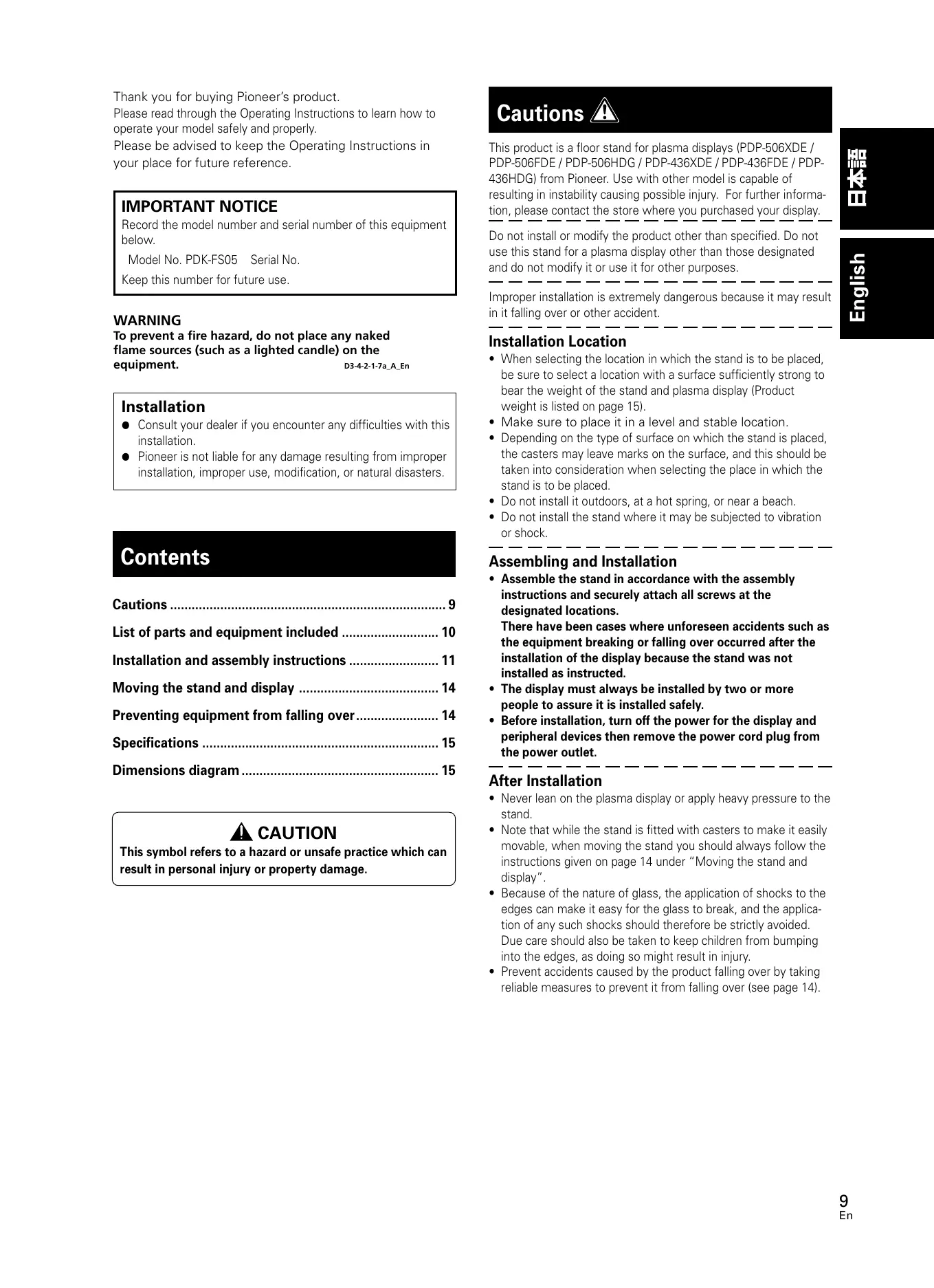
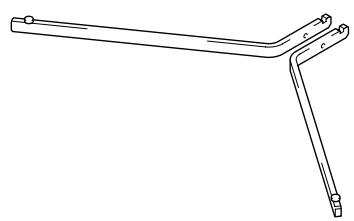
- Center support column x1
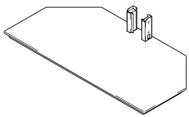
- Base x1
- PDP bracket x1
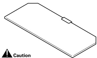
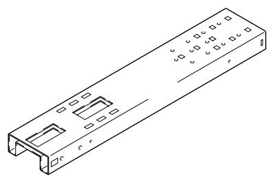
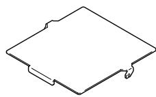
Glass panel x1
Glass stays (x2, one left and one right)
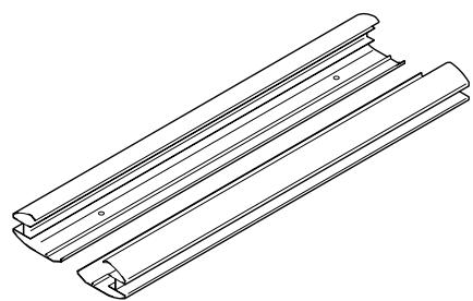
- Support column covers (x2, one left and one right)
The glass panel should be kept in its packing box until you are ready to attach it to the stand to guard against breakage.
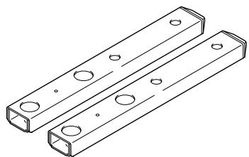
- Long support legs x2
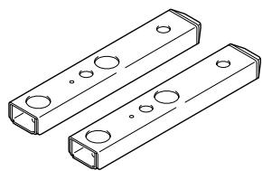
- Short support legs x2
- Cable cover x1 (for attachment to support column)
Cap x1
(Pleases refer to the table for Procedure 3 on page 11 for usage.)
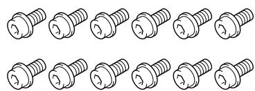
- Short hexagonal bolts (M8 x 16 mm: black) x12
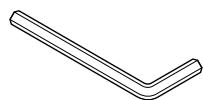
- Hexagonal wrench x1 (Opposite side 6 mm for M8 use)
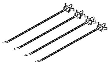
- Cable clamps x4
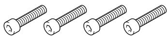
- Middle hexagonal bolts (M8 x 35 mm: black) x4

- Screws (M4 x 10 mm: silver) x4


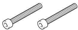
- Long hexagonal bolts (M8 x 60 mm: silver) x2

- Screws (M4 x 10 mm: black) x2

- Operating instructions (This document) x1
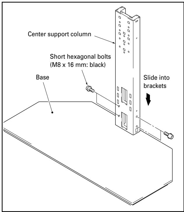
1 Slide center support column into brackets on the base and use short hexagonal bolts to fix it into place (4 locations).
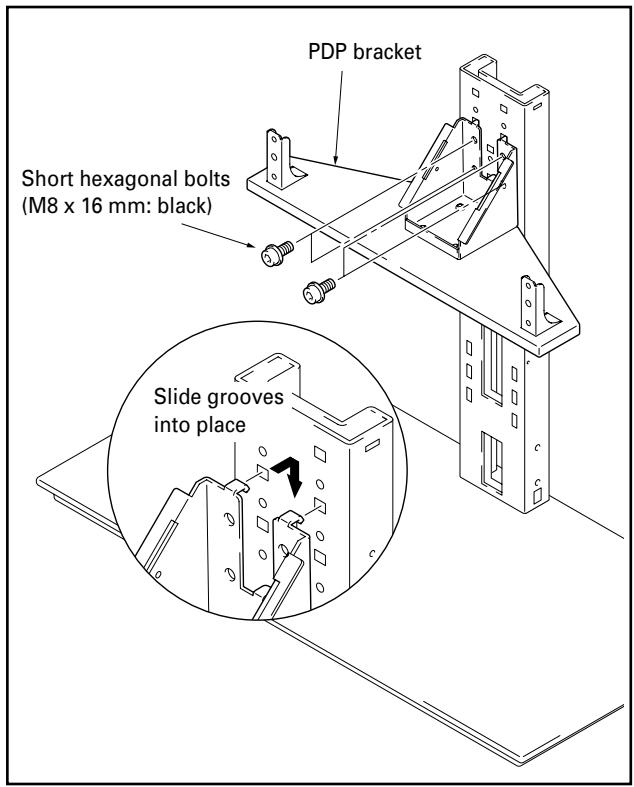
2 Use short hexagonal bolts to attach PDP bracket to center support column (bolts must be screwed in four locations).
The bracket may be screwed into the upper holes, middle holes, or lower holes of the center support column to adjust the height of the display. The middle holes are designed to be used for standard installation.
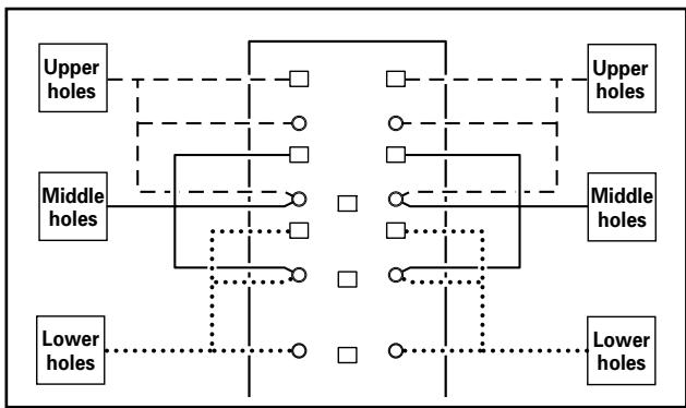
Locations of holes on center support column for attachment of PDP bracket
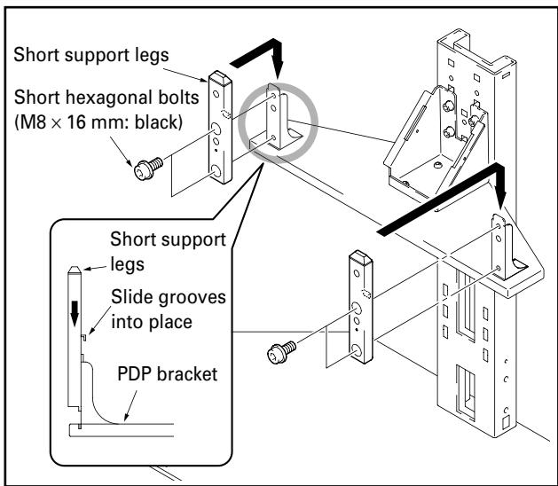
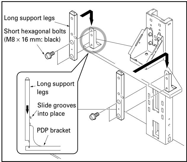
3 Attach the long support legs or short support legs to the PDP bracket with the short hexagonal bolts (4 locations).
Table of parts included with each plasma display
| Plasma Display | PDP-506XDE PDP-506FDE PDP-506HDG | PDP-436XDE PDP-436FDE PDP-436HDG | One body type plasma display | ||
| Location of speaker | Side | Side | Under | - | |
| Support legs attachment method | A | A | B | B | |
| Used parts | Support legs | Short ×2 | Short ×2 | Long ×2 | Long ×2 |
| Plasma display attachment use top hexagonal bolts | Middle ×2 | Middle ×2 | Middle ×2 | Long ×2 | |
| Plasma display attachment use bottom hexagonal bolts | Middle ×2 | Middle ×2 | Middle ×2 | Middle ×2 | |
| Unused parts | Support legs | Long ×2 | Long ×2 | Short ×2 | Short ×2 |
| Hexagonal bolts | Long ×2 | Long ×2 | Long ×2 | Middle ×2 | |
Note
Be sure to carefully store the unused support legs, the bolts, the hexagonal wrench, and the Operating Instructions together.

When installing speakers at the sides of the plasma display
- Use the short support legs.
- Use the hexagonal wrench included with the stand to do so.
B When installing speakers below the plasma display or one body type plasma display
- Use the long support legs.
- Use the hexagonal wrench included with the stand to do so.

The types of plasma displays which may be used with the stand differ depending on the length of the support legs attached to the PDP bracket, so you should check to see if the display to be attached is compatible before proceeding.
4 Attach plasma display to support legs.
Fit the stand's support columns to the bottom of the plasma display as indicated by the arrows, then slowly insert them vertically. Be extremely careful not to insert the support legs of the stand into any part of the plasma display other than the stand insertion slots. Note that doing so might damage the plasma display panel or its ports or result in the warping of the stand. If the plasma display is fitted with handles, it is usually best to hold the display by its handles when attaching it to the support legs.
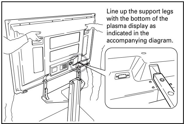

- Be sure to work with at least one other person when attaching the display.
- Be careful not to allow your fingers get caught between the display and support legs.
- If the PDP bracket has been placed into the upper bracket holes and speakers are to be installed below the plasma display or one body type plasma display, care must be taken to ensure that the display is firmly supported as its position will be higher.
5 Use the middle or the long hexagonal bolts to fix the plasma display to the support legs (4 locations).
Please install starting with the bolts on the top.
When installing the PDP-506XDE / PDP-506FDE / PDP-506HDG / PDP-436XDE / PDP-436FDE / PDP-436HDG
Use the following bolts to fix it with the hexagonal wrench. Top Middle hexagonal bolts (M8 x 35 mm: black) Bottom Middle hexagonal bolts (M8 x 35 mm: black)
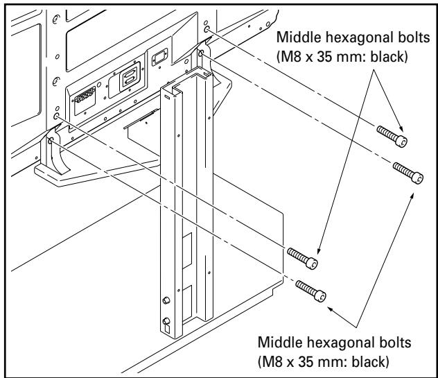
- If speakers are to be installed at the sides or the bottom of the plasma display, they should be attached at this phase.
- See the installation instructions provided with your speakers for instructions on how to install them.
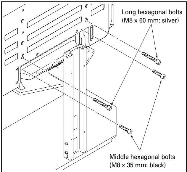
When installing the one body type plasma display
Use the following bolts to fix it with the hexagonal wrench. Top ......... Long hexagonal bolts (M8 x 60 mm: silver) Bottom ......... Middle hexagonal bolts (M8 x 35 mm: black)
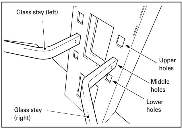
6 Attach left and right glass stays to support column.
① Insert the glass stays into the holes provided, pushing them all the way into the holes so that they point slightly downwards.
② Press down on the tips of the glass stays to lower them and fit the indentations into frames.
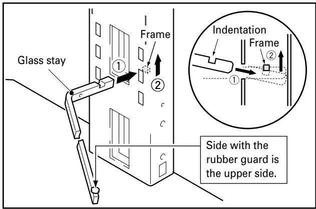
Glass stays may be inserted into the upper, middle, or lower holes to adjust the height of the glass panel (The middle holes are designed to be used for standard installation).
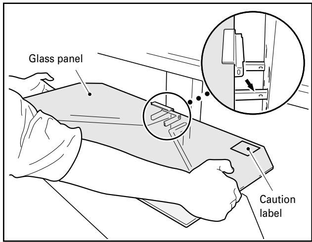
7 Attach the glass panel to the glass stays.
① Place the glass panel on top of the glass stays.
Note
The glass panel should be installed with the warning label facing upwards.
Fix it with the screws (M4 x 10 mm: black) (2 locations: left and right).
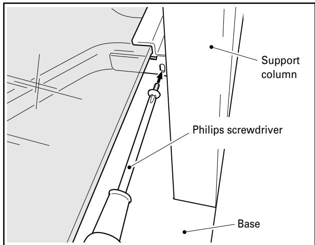

Be sure to use the screws to fix the glass panel into place. Note that failing to do so could cause the glass panel to fall off if you come into contact with it and result in the panel breaking.
8 Place equipment onto glass panel and connect equipment to display.
- Place the equipment to be connected to the display onto the glass panel and then connect the equipment to the display.
- Note that the glass panel and base are designed to be able to withstand loads of up to only 20 kilograms (44.1 lbs), and that the weight of the equipment placed onto the glass panel should never exceed this limit.
Note
When a video deck is placed on the glass panel, there may be times when the video deck interferes with the plasma display and causes distortion in the picture depending on the place of the video deck or on other conditions. If this happens, place the video deck on the base instead to avoid interference.
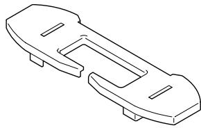
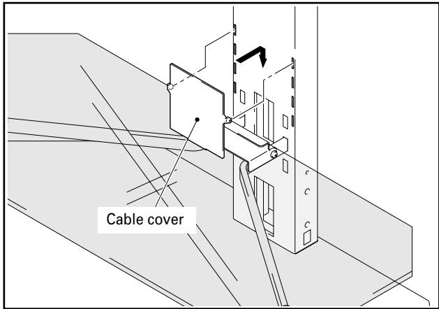
9 Attach cable cover.
Fit the cable cover into the center support column.
Note
Be careful when doing so not to allow cables to get caught between the cable cover and the cable insertion slots.
10 Attach one support column cover to the center support column to cover cables, and fix it with screws (M4 x 10 mm: silver) (2 screws, on the top and bottom).
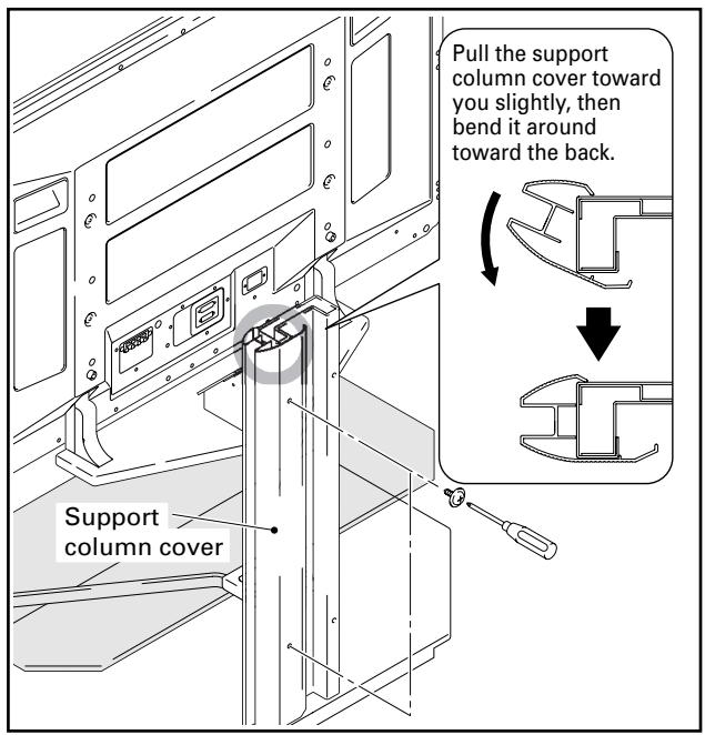

Be careful not to allow cables to become caught in the support column covers.
11 Follow the same procedure to attach the support column cover on the other side, and fix it with screws (M4 x 10 mm: silver) (2 screws, on the top and bottom).
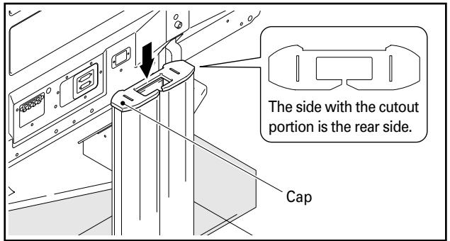
12 Attach cap.
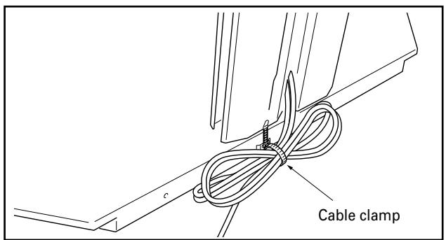
13 Attach cable clamps.
The cable clamps may be used to bundle up any excess lengths of cable as shown in the diagram below.
Note
Be careful not to step on any cables when moving the stand.
Moving the stand and display
- When moving the stand and display, hold the stand by its center support column.
- When moving the stand and display, never do so by holding the plasma display, speakers, or glass panel, as doing so might result in breakage or damage to the equipment.
- When moving over an uneven surface of any kind, pick up the stand and display by the base of the stand.
- Be careful when you place the stand and display on a thick carpeted surface, because when you do, the fibers may become entwined in the casters preventing them from rolling.
- When moving the stand and display. Depending on the type of surface on which the stand is placed, the casters may leave marks on the surface, and this should be taken into consideration when selecting the place in which the stand is to be placed.
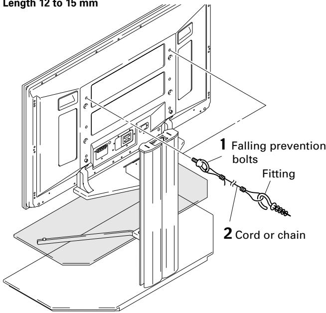
Preventing equipment from falling over
After installing the stand, be sure to take special care to ensure that the Plasma Display will not fall over.
1 Attaching falling prevention bolts to the Plasma Display.
2 Using strong cords or chains to stabilize it appropriately and firmly to a wall, pillar, or other sturdy element.
Perform this work in the same way on the left and right sides.
Note
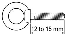
Use falling prevention bolts, ropes, chains, and fittings that are available on the market.
Recommended hook: Nominal diameter M8 Length 12 to 15mm
External dimensions 960 (W) x 760 (H) x 478 (D) mm
[When using PDP bracket at the middle holes, and when using the short support legs]
Weight 33.0 kg (72.8 lbs) [When using the short support legs]
- The above specifications and exterior may be modified without prior notice to improve the product.
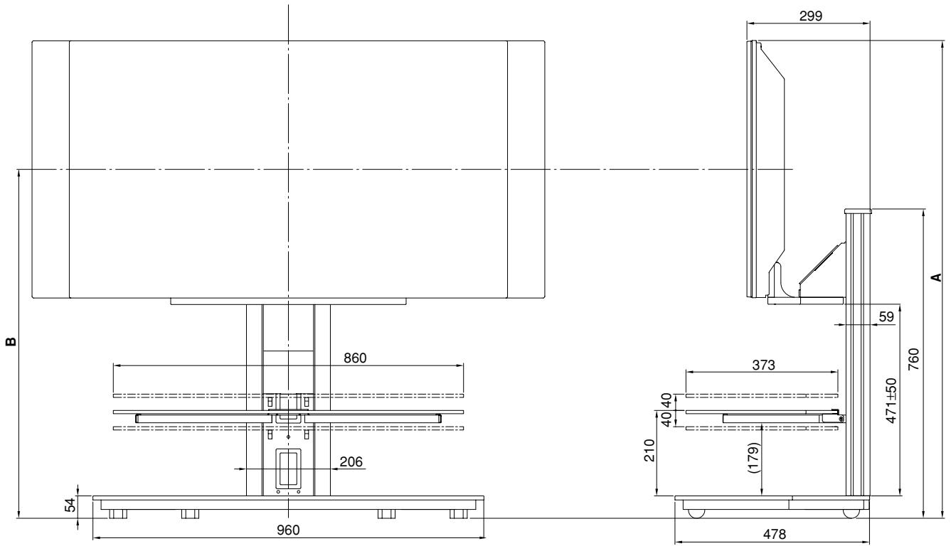
Dimensions diagram
(Units: mm)
| Plasma display | Location of speakers | Position | Full height (Dimensions A) | Center of screen (Dimensions B) |
| PDP-436XDE | At sides of plasma display | Upper | 1,223 | 907 |
| PDP-436FDE | Middle | 1,173 | 857 | |
| PDP-436HDG | Lower | 1,123 | 807 | |
| Below plasma display | Upper | 1,286 | 970 | |
| Middle | 1,236 | 920 | ||
| Lower | 1,186 | 870 | ||
| PDP-506XDE | At sides of plasma display | Upper | 1,308 | 950 |
| PDP-506FDE | Middle | 1,258 | 900 | |
| PDP-506HDG | Lower | 1,208 | 850 | |
| One body type plasma display | - | Upper | 1,286 | 970 |
| Middle | 1,236 | 920 | ||
| Lower | 1,186 | 870 |
Model N. PDK-FS05 Serial No.
AFTER-SALES SERVICE FOR PIONEER PRODUCTS
Please contact the dealer or distributor from where you purchased the product for its after-sales service (including warranty conditions) or any other information. In case the necessary information is not available, please contact the Pioneer's subsidiaries (regional service headquarters) listed below:
PLEASE DO NOT SHIP YOUR PRODUCT TO THE COMPANIES at the addresses listed below for repair without advance contact, for these companies are not repair locations.
AMERICA
PIONEER ELECTRONICS (USA) INC.
CUSTOMER SUPPORT DIVISION
P.O. BOX 1760, LONG BEACH, CA 90801-1760, U.S.A.
CUSTOMER SERVICE HOTLINE : (800) 421- 1404
EUROPE
PIONEER EUROPE NV
EUROPEAN SERVICE DIVISION
HAVEN 1087, KEETBERGLAAN 1, B-9120 MELSELE, BELGIUM
ASEAN
PIONEER ELECTRONICS ASIACENTRE PTE. LTD.
SERVICE DEPARTMENT
253, ALEXANDRA ROAD #04-01 SINGAPORE 159936
JAPAN AND OTHERS
PIONEER CORPORATION (HEAD OFFICE)
CUSTOMER SUPPORT CENTER
Printed on recycled paper.
Published by Pioneer Corporation.
Copyright © 2005 Pioneer Corporation.
All rights reserved.
八才二株式会社
PIONEER ELECTRONICS (USA) INC.
P.O. BOX 1540, Long Beach, California 90810-1540, U.S.A. TEL: (800) 421-1404
PIONEER ELECTRONICS OF CANADA, INC.
300 Allstate Parkway, Markham, Ontario L3R OP2, Canada TEL: 1-877-283-5901
PIONEER EUROPE NV
Haven 1087, Keetberglaan 1, B-9120 Melsele, Belgium TEL: 03/570.05.11
PIONEER ELECTRONICS ASIACENTRE PTE. LTD.
253 Alexandra Road, #04-01, Singapore 159936 TEL: 65-6472-7555
PIONEER ELECTRONICS AUSTRALIA PTY. LTD.
178-184 Boundary Road, Braeside, Victoria 3195, Australia, TEL: (03) 9586-6300
PIONEER ELECTRONICS DE MEXICO S.A. DE C.V.
Blvd. Manuel Avila Camacho 138 10 piso Col.Lomas de Chapultepec, Mexico,D.F. 11000 TEL: 55-9178-4270
- IMPORTANT NOTICE
- WARNING
- Installation
- Contents
- CAUTION
- Cautions
- Installation Location
- Assembling and Installation
- After Installation
- List of parts and equipment included
- Note
- When installing speakers at the sides of the plasma display
- B When installing speakers below the plasma display or one body type plasma display
- Attach plasma display to support legs.
- Use the middle or the long hexagonal bolts to fix the plasma display to the support legs (4 locations).
- When installing the one body type plasma display
- Attach left and right glass stays to support column.
- Attach the glass panel to the glass stays.
- Place equipment onto glass panel and connect equipment to display.
- Attach cable cover.
- Moving the stand and display
- Preventing equipment from falling over
- AFTER-SALES SERVICE FOR PIONEER PRODUCTS
- AMERICA
- EUROPE
- ASEAN
- JAPAN AND OTHERS
- 八才二株式会社
- PIONEER ELECTRONICS (USA) INC.
- PIONEER ELECTRONICS OF CANADA, INC.
- PIONEER EUROPE NV
- PIONEER ELECTRONICS ASIACENTRE PTE. LTD.
- PIONEER ELECTRONICS AUSTRALIA PTY. LTD.
- PIONEER ELECTRONICS DE MEXICO S.A. DE C.V.
Brand : PIONEER
Model : PDK-FS05
Category : Electronic device stand