
PDK-FS04 - Electronic device stand PIONEER - Free user manual and instructions
Find the device manual for free PDK-FS04 PIONEER in PDF.
| Product Type | Stand for plasma screen |
| Brand | PIONEER |
| Model | PDK-FS04 |
| Compatibility | PIONEER plasma screens PDP-505XDE, PDP-435XDE, PDP-505HDE, PDP-435HDE, PDP-435FDE, PDP-505HDG, PDP-435HDG |
| Weight of stand only | 32.7 kg |
| Total weight (stand + screen) | Up to 71.1 kg depending on model and configuration |
| Total height (depending on configuration) | From 1,126 mm to 1,417 mm |
| Maximum load of glass shelf | 20 kg |
| Materials | Steel, glass |
| Main features | Adjustable screen height, glass shelf for devices, cable management, casters for mobility |
| Safety | Anti-tip attachment using bolts and cables (not supplied) |
| Tools required for assembly | Philips screwdriver (not supplied) |
| Care and cleaning | Clean with a soft, dry cloth. Do not use abrasive products. |
| Included parts | Center column, base, glass shelf, brackets, screws, hex key, covers, cable ties, instruction manual |
| Repairability | Spare parts available from authorized dealer |
| Warranty | Consult your dealer |
Frequently Asked Questions - PDK-FS04 PIONEER
User questions about PDK-FS04 PIONEER
0 question about this device. Answer the ones you know or ask your own.
Ask a new question about this device
Download the instructions for your Electronic device stand in PDF format for free! Find your manual PDK-FS04 - PIONEER and take your electronic device back in hand. On this page are published all the documents necessary for the use of your device. PDK-FS04 by PIONEER.
USER MANUAL PDK-FS04 PIONEER
Operating instructions
Mode d'emploi
Bedienungsanleitung
natural_image
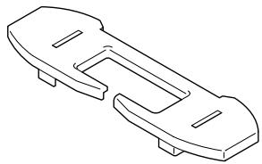
Isometric line drawing of a rectangular electronic component with slots and mounting holes (no text or symbols)- ベース × 1

natural_image
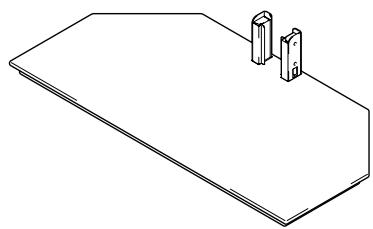
Isometric line drawing of a flat rectangular object with two vertical pins on top (no text or symbols)natural_image
Technical line drawing of a mechanical bracket assembly (no text or symbols)- 棚ガラス × 1
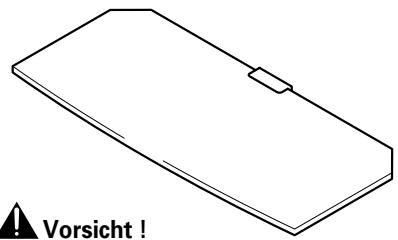
natural_image
Simple line drawing of a rectangular object with a horizontal bar and a triangular end, no text or symbols present.- ガラスステイ(左右:各1)×2
natural_image
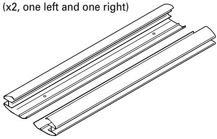
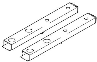
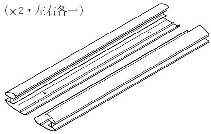
Line drawing of a Y-shaped metal bracket with three end caps (no text or symbols)- 支柱 L × 2
[長い支柱]

natural_image
Technical line drawing of two rectangular metal brackets with holes, no text or symbols present注意
natural_image
Technical line drawing of a mechanical component with flanged ends and a central cutout (no text or symbols)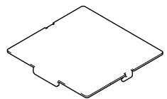
natural_image
Isometric line drawing of a mechanical component with two flanges and a central slot (no text or symbols)natural_image
Technical line drawing of a mechanical bracket or support structure (no text or symbols)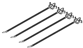
natural_image
Four identical diagonal lines with small protrusions, no text or symbols presentnatural_image
Illustration of eight different types of screws arranged in two rows (no text or symbols)Thank you for buying Pioneer's product.
Please read through the Operating Instructions to learn how to operate your model safely and properly.
Please be advised to keep the Operating Instructions in your place for future reference.
Installation
- Consult your dealer if you encounter any difficulties with this installation.
- Pioneer is not liable for any damage resulting from improper installation, improper use, modification, or natural disasters.
Contents
Cautions 9
List of parts and equipment included 10
Installation and assembly instructions .... 11
Moving the stand and display 14
Preventing equipment from falling over.... 14
External dimensions diagram 15

CAUTION
This symbol refers to a hazard or unsafe practice which can result in personal injury or property damage.
Cautions

This product is a floor stand for plasma displays (PDP-505XDE / PDP-435XDE / PDP-505HDE / PDP-435HDE / PDP-435FDE / PDP-505HDG / PDP-435HDG) from Pioneer. Use with other model is capable of resulting in instability causing possible injury. For further information, please contact the store where you purchased your display.
Do not install or modify the product other than specified. Do not use this stand for a plasma display other than those designated and do not modify it or use it for other purposes.
Improper installation is extremely dangerous because it may result in it falling over or other accident.
Installation Location
- When selecting the location in which the stand is to be placed, be sure to select a location with a surface sufficiently strong to bear the weight of the stand and plasma display (Product weight is listed on p. 15).
- Make sure to place it in a level and stable location.
- Depending on the type of surface on which the stand is placed, the casters may leave marks on the surface, and this should be taken into consideration when selecting the place in which the stand is to be placed.
- Do not install it outdoors, at a hot spring, or near a beach.
- Do not install the stand where it may be subjected to vibration or shock.
Assembling and Installation
- Assemble the stand in accordance with the assembly instructions and securely attach all screws at the designated locations.
There have been cases where unforeseen accidents such as the equipment breaking or falling over occurred after the installation of the display because the stand was not installed as instructed. - The display must always be installed by two or more people to assure it is installed safely.
- Before installation, turn off the power for the display and peripheral devices then remove the power cord plug from the power outlet.
After Installation
- Never lean on the plasma display or apply heavy pressure to the stand.
- Note that while the stand is fitted with casters to make it easily movable, when moving the stand you should always follow the instructions given on p. 14 under Moving the stand and display.
- Because of the nature of glass, the application of shocks to the edges can make it easy for the glass to break, and the application of any such shocks should therefore be strictly avoided.
Due care should also be taken to keep children from bumping into the edges, as doing so might result in injury.
- Prevent accidents caused by the product falling over by taking reliable measures to prevent it from falling over (see Page 14).
List of parts and equipment included
Be sure to check that all the parts and equipment listed below have been included before beginning to assemble your stand.
- Note that a Philips screwdriver (not included) is required for assembly.
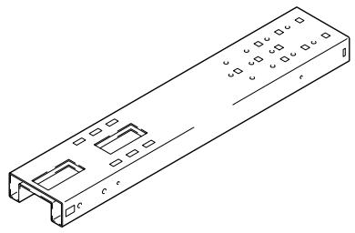
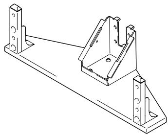
- Center support column x1
natural_image
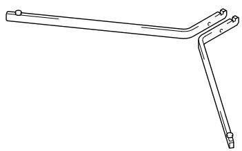
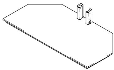
Isometric line drawing of a rectangular electronic device with internal slots and mounting holes (no text or symbols)- Base x1
natural_image
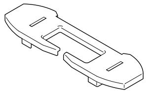
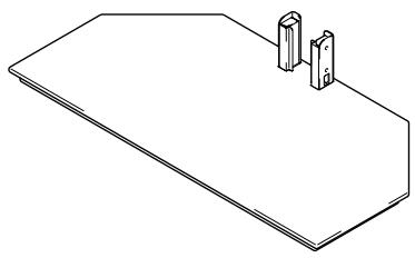
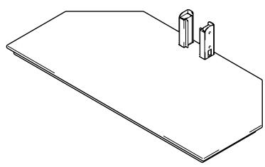
Isometric line drawing of a flat rectangular plate with two vertical cylindrical components on top (no text or symbols)- PDP bracket x1 (with short support legs)
natural_image
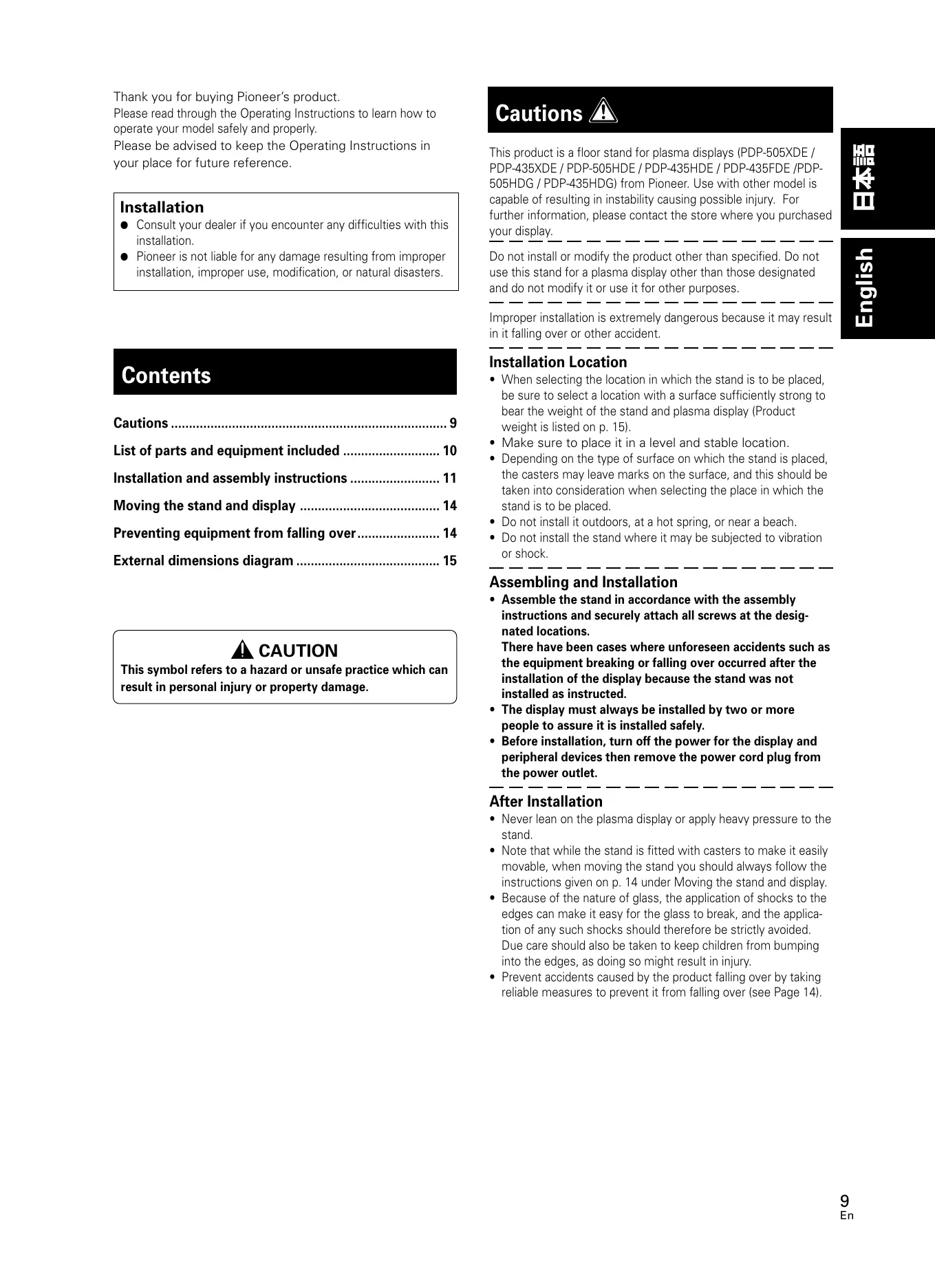
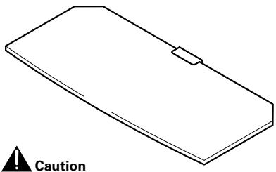
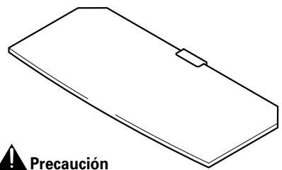
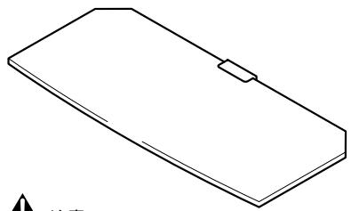
Technical line drawing of a metal bracket assembly (no text or symbols)- Glass panel x1
natural_image
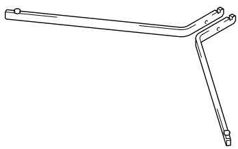
Isometric line drawing of a rectangular object with a small protrusion and a warning symbol below (no text or labels)- Glass stays (x2, one left and one right)
natural_image
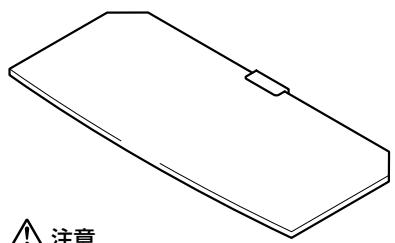
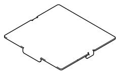
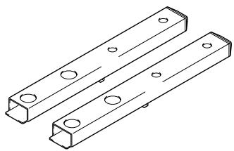
Line drawing of a Y-shaped metal bracket with mounting holes (no text or symbols)- Long support legs x2

natural_image
Technical line drawing of two rectangular metal brackets with holes, no text or symbols presentThe glass panel should be kept in its packing box until you are ready to attach it to the stand to guard against breakage.
-
Cable cover x1 (for attachment to support column)
-
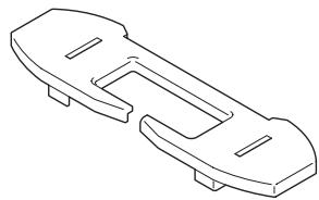
Cap x1
natural_image
Line drawing of a mechanical component with two notches and a central slot (no text or symbols)- Support column covers (x2, one left and one right)
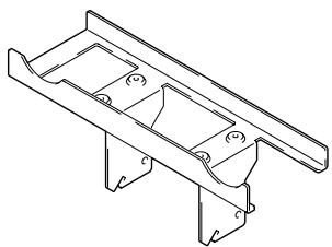
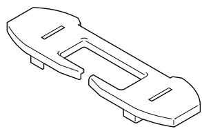
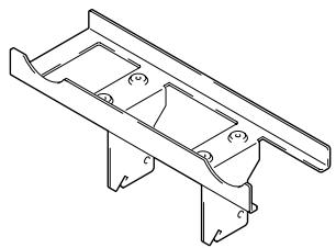
- MR holder x1
natural_image
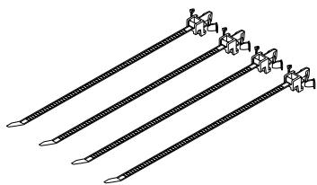
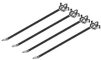
Technical line drawing of a mechanical bracket or support structure (no text or symbols)- Cable clamps x4
natural_image
Four identical diagonal lines with small protrusions, resembling a stylized pen or tool (no text or symbols)-
Hexagonal wrench x1 (Opposite side 6 mm for M8 use)
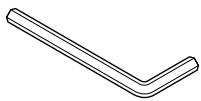
-
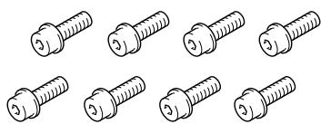
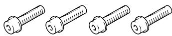
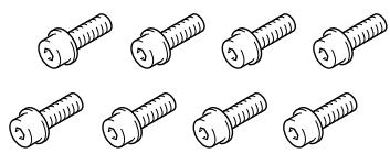
Short hexagonal bolts (M8 x 16 mm) x8
natural_image
Illustration of eight different types of screws arranged in two rows (no text or symbols)-
Screws (M4 x 10 mm: silver) x4

-
Screws (M4 x 10 mm: black) x2

- Screws (M4 x 10 mm) x2
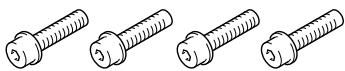
Long hexagonal bolts (M8 x 35 mm) x4

- Operating instructions (This document) x1

Installation and assembly instructions
(Stand shown below is a 43-inch display stand with short support legs)
1 Slide center support column into brackets on the base and use short hexagonal bolts to fix it into place (4 locations).
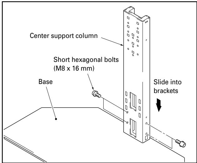
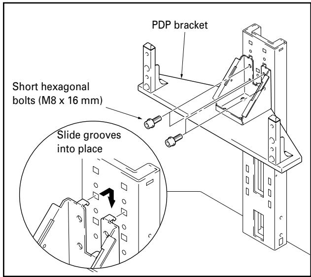
2 Use short hexagonal bolts to attach PDP bracket to center support column (bolts must be screwed in four locations).
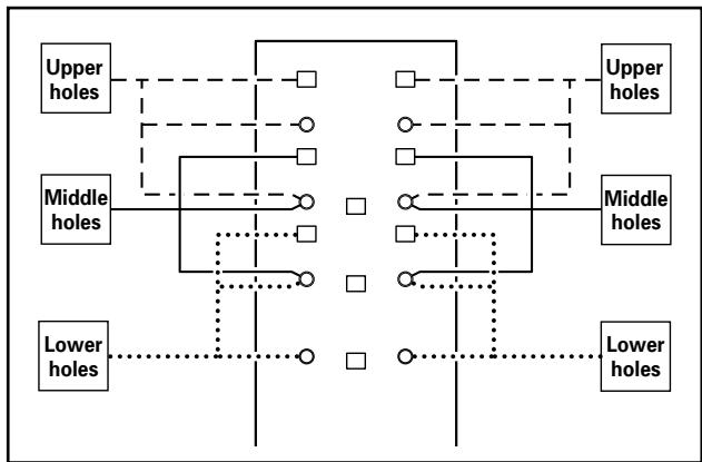
The bracket may be screwed into the upper holes, middle holes, or lower holes of the center support column to adjust the height of the display. The middle holes are designed to be used for standard installation.
✿ Locations of holes on center support column for attachment of PDP bracket
flowchart
graph TD
    A["Upper holes"] --> B["Upper holes"]
    C["Middle holes"] --> D["Middle holes"]
    E["Lower holes"] --> F["Lower holes"]
    B --> G[" "]
    D --> H[" "]
    F --> I[" "]
When installing speakers below the plasma display
Remove the short support legs attached to the PDP bracket and replace them with the long support legs (Use the hexagonal wrench included with the stand to do so).
Note
Use the short support legs if speakers are to be installed at the sides of the plasma display.
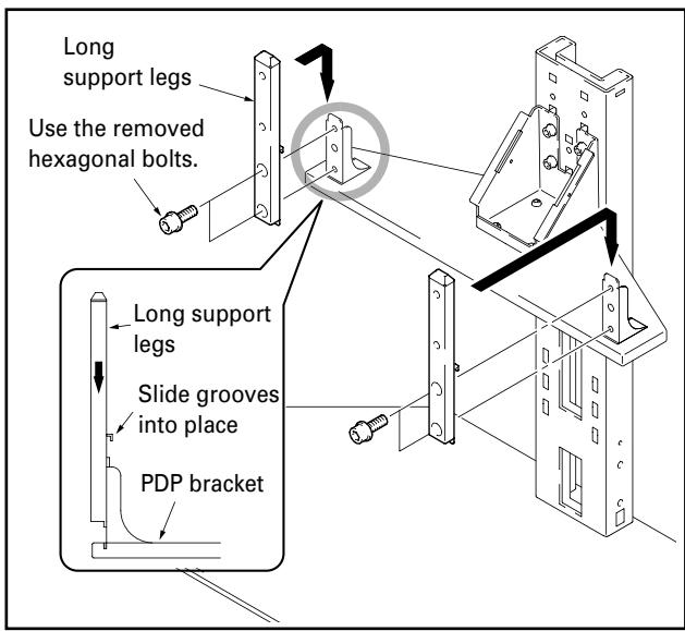

The types of plasma displays which may be used with the stand differ depending on the length of the support legs attached to the PDP bracket, so you should check to see if the display to be attached is compatible before proceeding.
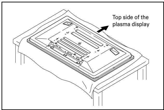
✿ Precautions when installing speakers below the plasma display
- Place the plasma display as shown in the figure.
- See the installation instructions provided with your speakers for instructions on how to install them.
Note
- Spread a sheet so that the plasma display will not be scratched or damaged.
● Always install it on top of a stable table or similar surface.
3 Attach plasma display to support legs.
Fit the stand's support columns to the bottom of the plasma display as indicated by the arrows, then slowly insert them vertically. Be extremely careful not to insert the support legs of the stand into any part of the plasma display other than the stand insertion slots. Note that doing so might damage the plasma display panel or its ports or result in the warping of the stand.
If the plasma display is fitted with handles, it is usually best to hold the display by its handles when attaching it to the support legs.
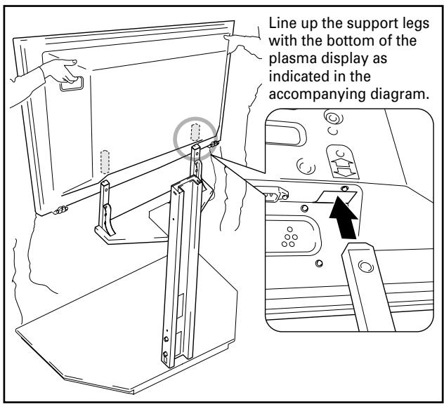

- Be sure to work with at least one other person when attaching the display.
- Be careful not to allow your fingers get caught between the display and support legs.
- If the PDP bracket has been placed into the upper bracket holes and speakers are to be installed below the plasma display, care must be taken to ensure that the display is firmly supported as its position will be higher.
4 Use the long hexagonal bolts to fix the plasma display to the support legs (4 locations).
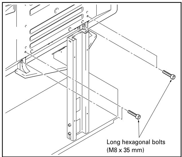
- If speakers are to be installed at the sides of the plasma display, they should be attached at this phase.
- See the installation instructions provided with your speakers for instructions on how to install them.
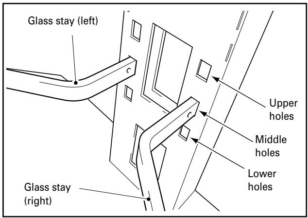
5 Attach left and right glass stays to support column.
① Insert the glass stays into the holes provided, pushing them all the way into the holes so that they point slightly downwards.
② Press down on the tips of the glass stays to lower them and fit the indentations into pins.
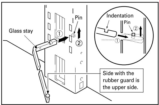
Glass stays may be inserted into the upper, middle, or lower holes to adjust the height of the glass panel (The middle holes are designed to be used for standard installation).
6 Fit glass panel into glass stays.
Note
The glass panel should be installed with the warning label facing upwards.
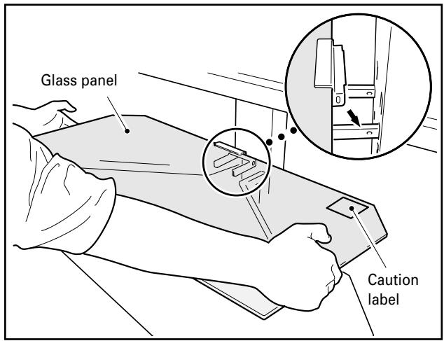
7 Fix it with the screws (M4 x 10 mm: black) (2 locations: left and right).
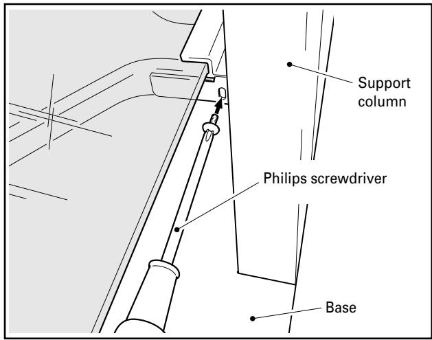

Be sure to use the screws to fix the glass panel into place. Note that failing to do so could cause the glass panel to fall off if you come into contact with it and result in the panel breaking.
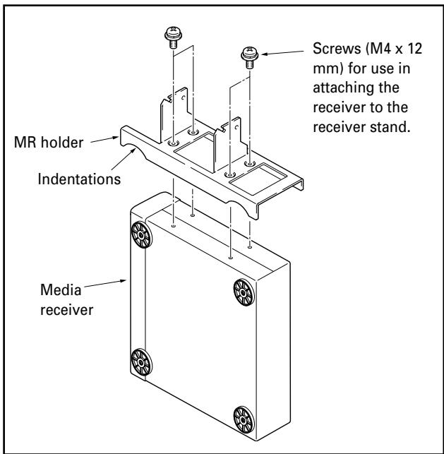
8 What to do when attaching an upright media receiver.
① Fit the MR holder over the sides of the media receiver and fix into place using the four screws (M4 x 12 mm) provided for use in attaching the receiver to the receiver stand.
Note
- The legs of the MR holder are on the side of the holder with the indentations. Be sure to attach the holder in the correct direction.
- Do not attach the MR holder to anything other than a media receiver.
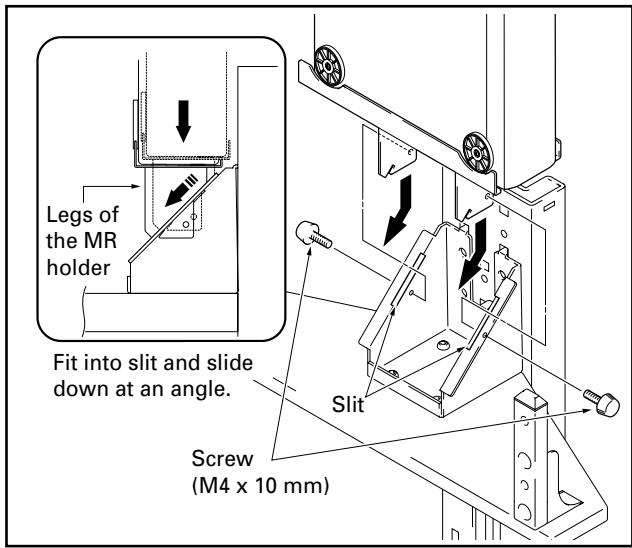
② Fit the legs of the MR holder into the slit of the PDP bracket, slide down at an angle, and fix into place with screws (M4 x 10mm).
Note
- Do not attach any other equipment other than a media receiver in this location.
- Never place vases, dehumidifiers, or any other objects or devices with liquids in them on top of the PDP bracket.
9 Place equipment onto glass panel and connect equipment to display.
- Place the equipment to be connected to the display onto the glass panel and then connect the equipment to the display.
- Note that the glass panel and base are designed to be able to withstand loads of up to only 20 kilograms (44.1 lbs), and that the weight of the equipment placed onto the glass panel should never exceed this limit.
Note
When a video deck is placed on the glass panel, there may be times when the video deck interferes with the plasma display and causes distortion in the picture depending on the place of the video deck or on other conditions. If this happens, place the video deck on the base instead to avoid interference.
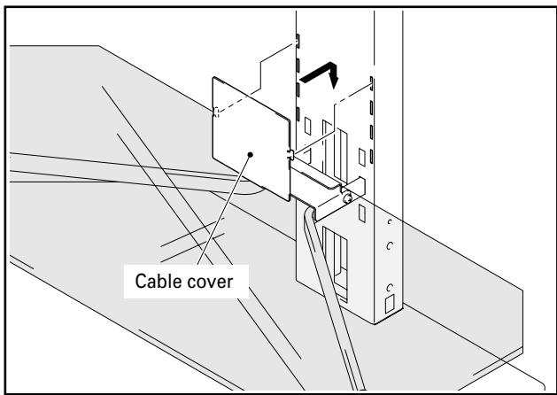
10 Attach cable cover.
Fit the cable cover into the center support column.
Note
Be careful when doing so not to allow cables to get caught between the cable cover and the cable insertion slots.
Installation and assembly instructions
11 Attach one support column cover to the center support column to cover cables, and fix it with screws (M4 x 10 mm: silver) (2 screws, on the top and bottom).
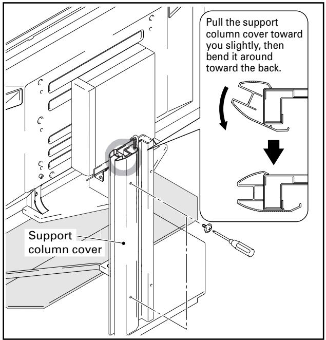

Be careful not to allow cables to become caught in the support column covers.
12 Follow the same procedure to attach the support column cover on the other side, and fix it with screws (M4 x 10 mm: silver) (2 screws, on the top and bottom).
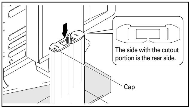
13 Attach cap.
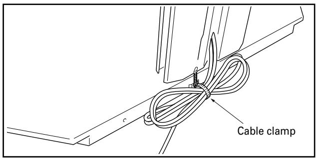
14 Attach cable clamps.
The cable clamps may be used to bundle up any excess lengths of cable as shown in the diagram below.
Note
Be careful not to step on any cables when moving the stand.
Moving the stand and display
- When moving the stand and display, hold the stand by its center support column.
- When moving the stand and display, never do so by holding the plasma display, speakers, or glass panel, as doing so might result in breakage or damage to the equipment.
- When moving over an uneven surface of any kind, pick up the stand and display by the base of the stand.
- Be careful when you place the stand and display on a thick carpeted surface, because when you do, the fibers may become entwined in the casters preventing them from rolling.
- When moving the stand and display. Depending on the type of surface on which the stand is placed, the casters may leave marks on the surface, and this should be taken into consideration when selecting the place in which the stand is to be placed.
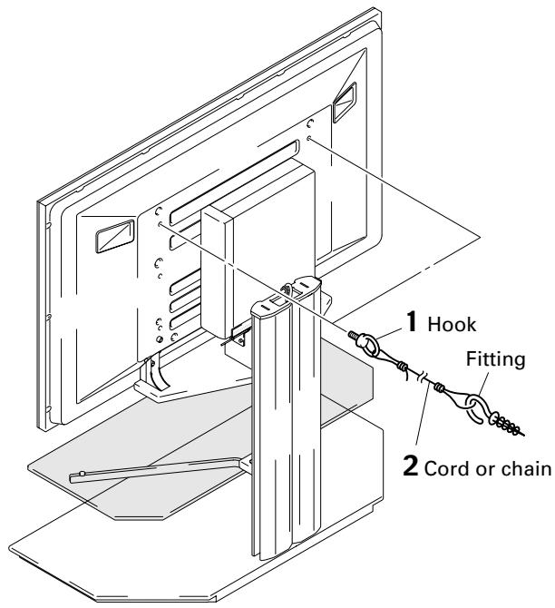
Preventing equipment from falling over
After installing the stand, be sure to take measures so that the equipment will not fall over.
1 Attaching falling prevention bolts (hooks) to the plasma display.
2 Using strong cords or chains to firmly stabilize it to a wall, pillar, or other sturdy element.
Perform the same procedure on the left and right, making sure when doing so that the lengths and positions of both restraints are symmetrical.
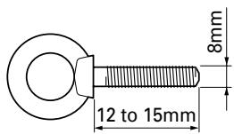
Note
Use hooks, ropes, chains, and fittings
that are available on the market.
Recommended hook:
Nominal diameter 8 mm
Length 12 to 15 mm
External dimensions diagram
Weight
Stand only: 32.7 kg (72.1 lbs)
Stand and plasma display:
63.1 kg (139.1 lbs) [When used with a PDP-435XDE/435HDE/435FDE/435HDG display with speakers (PDP-S22-LR) attached.]
64.3 kg (141.8 lbs) [When used with a PDP-435XDE/435HDE/435FDE/435HDG display with speakers (PDP-S26-LR) attached.]
69.8 kg (153.9 lbs) [When used with a PDP-505XDE/505HDE/505HDG display with speakers (PDP-S21-LR) attached.]
71.1 kg (156.7 lbs) [When used with a PDP-505XDE/505HDE/505HDG display with speakers (PDP-S25-LR) attached.]
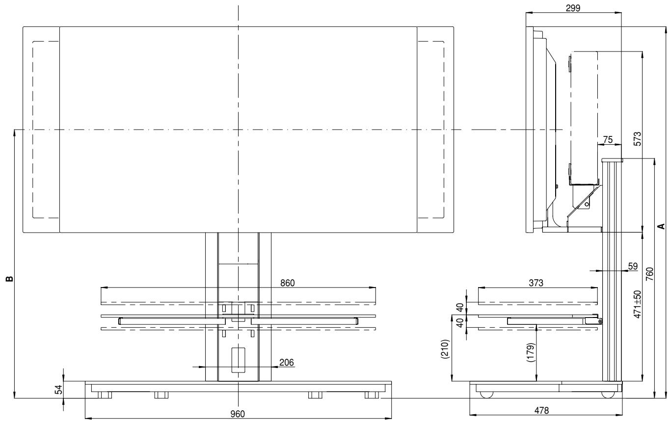
(Units: mm)
| Plasma display | Location of speakers | Position | Full height (Dimensions A) | Center of screen (Dimensions B) |
| PDP-435XDE | At sides of plasma display | Upper | 1,226 | 900 |
| PDP-435HDE | Middle | 1,176 | 850 | |
| PDP-435FDE | Lower | 1,126 | 800 | |
| PDP-435HDG | Below plasma display | Upper | 1,332 | 1,006 |
| Middle | 1,282 | 956 | ||
| Lower | 1,232 | 906 | ||
| PDP-505XDE | At sides of plasma display | Upper | 1,311 | 943 |
| PDP-505HDE | Middle | 1,261 | 893 | |
| PDP-505HDG | Lower | 1,211 | 843 | |
| Below plasma display | Upper | 1,417 | 1,049 | |
| Middle | 1,367 | 999 | ||
| Lower | 1,317 | 949 |
- The above specifications and exterior may be modified without prior notice to improve the product.
natural_image
Isometric line drawing of a rectangular electronic component with slots and mounting holes (no text or symbols)natural_image
Simple line drawing of a rectangular object with a protruding rod, labeled 'Attention' at the bottom (no other text or symbols)natural_image
Technical line drawing of a mechanical bracket or support structure (no text or symbols)natural_image
Illustration of eight different screwdrivers arranged in two rows (no text or symbols)natural_image
Isometric line drawing of a flat rectangular plate with two small cylindrical components on top (no text or symbols)natural_image
Line drawing of a Y-shaped metal bracket with mounting holes (no text or symbols)natural_image
Technical line drawing of a mechanical bracket or support structure (no text or symbols)natural_image
Technical line drawing of a metal bracket assembly (no text or symbols)- Pieds-supports longs x 2 unités

natural_image
Technical line drawing of two rectangular metal beams with holes, no text or symbols present- Couvercle x1 unité
natural_image
Line drawing of a mechanical component with two notches and a handle (no text or symbols)natural_image
Four identical elongated metal rods with pointed tips, arranged horizontally (no text or symbols)Be careful not to allow cables to become caught in the support column covers.
natural_image
Isometric line drawing of a rectangular electronic component with slots and mounting holes (no text or symbols)- Grundplatte: 1
natural_image
Isometric line drawing of a rectangular plate with two small protrusions on top (no text or symbols)natural_image
Technical line drawing of a mechanical bracket assembly (no text or symbols)- Glasplatte: 1
natural_image
Line drawing of a Y-shaped metal bracket with mounting holes (no text or symbols)- Lange Stützbeine: 2
natural_image
Technical line drawing of two rectangular metal brackets with bolt holes (no text or symbols)
Vorsicht!
natural_image
Technical line drawing of a mechanical component with parallel grooves and flanges (no text or symbols)natural_image
Isometric line drawing of a mechanical component with two notches and a central slot (no text or symbols)natural_image
Technical line drawing of a mechanical bracket or support structure (no text or symbols)natural_image
Four identical black-and-white line drawings of elongated, pointed objects with protrusions, arranged vertically (no text or symbols)natural_image
Illustration of eight different types of screws arranged in two rows (no text or symbols)natural_image
Isometric line drawing of a rectangular electronic component with slots and mounting holes (no text or symbols)natural_image
Simple line drawing of a rectangular object with a small protrusion and the label 'Attenzione' below (no other text or symbols)
Attenzione
natural_image
Technical line drawing of a mechanical component with flanged ends and a central bracket (no text or symbols)natural_image
Illustration of eight different types of screws (no text or symbols)natural_image
Isometric line drawing of a rectangular plate with two small protrusions on top (no text or symbols)natural_image
Simple line drawing of a Y-shaped metal bracket with mounting holes (no text or symbols)natural_image
Technical line drawing of a mechanical bracket or support structure (no text or symbols)• Viti (M4 x 10 mm : argento) x 4

• Viti (M4 x 10 mm : nere) x 2

• Viti (M4 x 10 mm) x 2

natural_image
Technical line drawing of a mechanical bracket assembly (no text or symbols)natural_image
Technical line drawing of two rectangular metal beams with holes, no text or symbols present- Coperchio x 1
natural_image
Isometric line drawing of a mechanical component with no text or symbolsnatural_image
Four identical elongated metal rods with pointed tips, arranged horizontally (no text or symbols)natural_image
Isometric line drawing of a rectangular electronic component with slots and mounting holes (no text or symbols)- Glaspaneel x 1
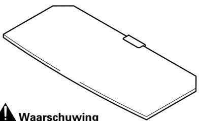

Waarschuwing
natural_image
Technical line drawing of a mechanical component with flanged ends and a central bracket (no text or symbols)natural_image
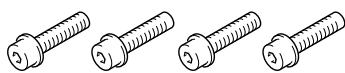
Illustration of eight different types of screws arranged in two rows (no text or symbols)• Lange zeskantbouten (M8 x 35 mm) x 4
- Voetstuk x 1
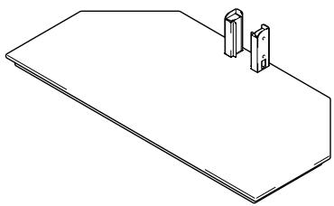
natural_image
Isometric line drawing of a rectangular plate with two small protrusions on top (no text or symbols)natural_image
Line drawing of a Y-shaped metal bracket with mounting holes (no text or symbols)natural_image
Technical line drawing of a mechanical bracket or support structure (no text or symbols)natural_image
Technical line drawing of a mechanical bracket assembly (no text or symbols)- Lange steunen x 2
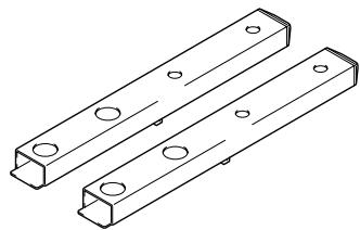
natural_image
Technical line drawing of two rectangular metal beams with holes, no text or symbols present- Kapje x 1

natural_image
Isometric line drawing of a mechanical component with no text or symbols- Kabelklemmen x 4
natural_image
Four identical elongated metal rods with pointed tips, arranged horizontally (no text or symbols)Gewicht
Standaard: 32,7 kg
natural_image
Isometric line drawing of a rectangular electronic component with slots and mounting holes (no text or symbols)- Base x 1
natural_image
Isometric line drawing of a flat surface with two vertical cylindrical objects on top (no text or symbols)natural_image
Technical line drawing of a metal bracket assembly (no text or symbols)- Panel de vidrio x 1
natural_image
Line drawing of a Y-shaped metal bracket with mounting holes (no text or symbols)natural_image
Technical line drawing of two rectangular metal beams with holes, no text or symbols present
Precaución
natural_image
Technical line drawing of a mechanical component with parallel grooves and a flanged end (no text or symbols)natural_image
Line drawing of a mechanical component with two notches and a central slot (no text or symbols)- Soporte MR x 1
natural_image
Technical line drawing of a mechanical bracket or support structure (no text or symbols)natural_image
Four identical black metal rods with pointed tips, arranged diagonally (no text or symbols)natural_image
Illustration of eight different types of screws (no text or symbols)- Tornillos (M4 x 10 mm: plateados) x 4

• Tornillos (M4 x 10 mm: negros) x 2

- Tornillos (M4 x 10 mm) x 2

natural_image
Isometric line drawing of a rectangular electronic component with slots and mounting holes (no text or symbols)- 基座 × 1
natural_image
Isometric line drawing of a rectangular plate with two vertical cylindrical components on top (no text or symbols)- PDP支架 × 1
(附有短支柱)

natural_image
Technical line drawing of a mechanical bracket assembly (no text or symbols)- 玻璃镶板 × 1
natural_image
Simple line drawing of a rectangular object with a horizontal line and a small rectangular element on top (no text or symbols)natural_image
Line drawing of a Y-shaped metal bracket with mounting holes (no text or symbols)- 長支柱 × 2
natural_image
Technical line drawing of two rectangular metal brackets with holes, no text or symbols present- 支柱外蓋
natural_image
Isometric line drawing of a mechanical component with two flanges and a central slot (no text or symbols)natural_image
Technical line drawing of a mechanical bracket or support structure (no text or symbols)- 絮線帯 × 4

natural_image
Four identical elongated metal rods with small protrusions, arranged diagonally (no text or symbols)- 短六角螺絲(M8×16公釐)×8
natural_image
Illustration of eight different types of screws (no text or symbols)AFTER-SALES SERVICE FOR PIONEER PRODUCTS
Please contact the dealer or distributor from where you purchased the product for its after-sales service (including warranty conditions) or any other information. In case the necessary information is not available, please contact the Pioneer's subsidiaries (regional service headquarters) listed below:
PLEASE DO NOT SHIP YOUR PRODUCT TO THE COMPANIES at the addresses listed below for repair without advance contact, for these companies are not repair locations.
AMERICA
PIONEER ELECTRONICS (USA) INC.
CUSTOMER SUPPORT DIVISION
P.O. BOX 1760, LONG BEACH, CA 90801-1760, U.S.A.
CUSTOMER SERVICE HOTLINE : (800) 421-1404
EUROPE
PIONEER EUROPE NV
EUROPEAN SERVICE DIVISION
HAVEN 1087, KEETBERGLAAN 1, B-9120 MELSELE, BELGIUM
ASEAN
PIONEER ELECTRONICS ASIACENTRE PTE. LTD.
SERVICE DEPARTMENT
253, ALEXANDRA ROAD #04-01 SINGAPORE 159936
JAPAN AND OTHERS
PIONEER CORPORATION (HEAD OFFICE)
CUSTOMER SUPPORT CENTER
Published by Pioneer Corporation.
Copyright © 2004 Pioneer Corporation.
All rights reserved.
パイオニア株式会社
PIONEER ELECTRONICS (USA) INC.
P.O. BOX 1540, Long Beach, California 90810-1540, U.S.A. TEL: (800) 421-1404
PIONEER ELECTRONICS OF CANADA, INC.
300 Allstate Parkway, Markham, Ontario L3R OP2, Canada TEL: 1-877-283-5901
PIONEER EUROPE NV
Haven 1087, Keetberglaan 1, B-9120 Melsele, Belgium TEL: 03/570.05.11
PIONEER ELECTRONICS ASIACENTRE PTE. LTD.
253 Alexandra Road, #04-01, Singapore 159936 TEL: 65-6472-7555
PIONEER ELECTRONICS AUSTRALIA PTY. LTD.
178-184 Boundary Road, Braeside, Victoria 3195, Australia, TEL: (03) 9586-6300
PIONEER ELECTRONICS DE MEXICO S.A. DE C.V.
Blvd.Manuel Avila Camacho 138 10 piso Col.Lomas de Chapultepec, Mexico,D.F. 11000 TEL: 55-9178-4270
- 注意
- Installation
- Contents
- CAUTION
- Cautions
- Installation Location
- Assembling and Installation
- After Installation
- List of parts and equipment included
- Installation and assembly instructions
- (Stand shown below is a 43-inch display stand with short support legs)
- Slide center support column into brackets on the base and use short hexagonal bolts to fix it into place (4 locations).
- Use short hexagonal bolts to attach PDP bracket to center support column (bolts must be screwed in four locations).
- When installing speakers below the plasma display
- Note
- Attach plasma display to support legs.
- Use the long hexagonal bolts to fix the plasma display to the support legs (4 locations).
- Attach left and right glass stays to support column.
- Fit glass panel into glass stays.
- Fix it with the screws (M4 x 10 mm: black) (2 locations: left and right).
- What to do when attaching an upright media receiver.
- Place equipment onto glass panel and connect equipment to display.
- Attach cable cover.
- Moving the stand and display
- Preventing equipment from falling over
- External dimensions diagram
- Weight
- Vorsicht!
- Attenzione
- Waarschuwing
- Gewicht
- Precaución
- AFTER-SALES SERVICE FOR PIONEER PRODUCTS
- AMERICA
- EUROPE
- ASEAN
- JAPAN AND OTHERS
- パイオニア株式会社
- PIONEER ELECTRONICS (USA) INC.
- PIONEER ELECTRONICS OF CANADA, INC.
- PIONEER EUROPE NV
- PIONEER ELECTRONICS ASIACENTRE PTE. LTD.
- PIONEER ELECTRONICS AUSTRALIA PTY. LTD.
- PIONEER ELECTRONICS DE MEXICO S.A. DE C.V.
Brand : PIONEER
Model : PDK-FS04
Category : Electronic device stand