
PBH 2800 RE - Rotary hammer BOSCH - Free user manual and instructions
Find the device manual for free PBH 2800 RE BOSCH in PDF.
| Brand | BOSCH |
| Model | PBH 2800 RE |
| Category | Rotary hammer (hammer drill) |
| Nominal power input | 720 W |
| Impact rate at rated speed | 4000 rpm |
| Single impact energy | 0 – 2.6 J |
| Rated speed | 1100 rpm |
| No-load speed | 0 – 1450 rpm |
| Tool holder | SDS-plus |
| Max. drilling diameter (concrete) | 26 mm |
| Max. drilling diameter (masonry with crown) | 68 mm |
| Max. drilling diameter (steel) | 13 mm |
| Max. drilling diameter (wood) | 30 mm |
| Weight (according to EPTA-Procedure 01/2003) | 3.0 kg |
| Protection class | II (double insulation) |
| Speed adjustment | Electronic, preselecting wheel |
| Rotation/impact stop | Yes, 4 positions: drilling, hammer drilling, Vario-Lock, chiseling |
| Rotation direction | Right/left (switch) |
| Auxiliary handle | Included, adjustable in position |
| Depth stop | Integrated into auxiliary handle |
| Overload clutch | Yes (safety in case of jamming) |
| Vario-Lock | Yes, 36 positions for chisel |
| Sound pressure level | 89 dB(A) |
| Sound power level | 100 dB(A) |
| Vibration (hammer drilling concrete) | a_h = 14 m/s², K = 1.5 m/s² |
| Included accessories | Gear chuck (on PBH 2800 RE), SDS-plus adapter, auxiliary handle, depth stop |
Frequently Asked Questions - PBH 2800 RE BOSCH
User questions about PBH 2800 RE BOSCH
0 question about this device. Answer the ones you know or ask your own.
Ask a new question about this device
Download the instructions for your Rotary hammer in PDF format for free! Find your manual PBH 2800 RE - BOSCH and take your electronic device back in hand. On this page are published all the documents necessary for the use of your device. PBH 2800 RE by BOSCH.
USER MANUAL PBH 2800 RE BOSCH
Power Tools Division
70745 Leinfelden-Echterdingen
Germany
www.bosch-pt.com
1 609 929 T39 (2009.09) PS / 160 WEU

1609929T39
PBH
2800 RE | 2900 FRE | 3000 FRE Set | 3000-2 FRE

BOSCH
Dr. Egbert Schneider Senior Vice President Engineering
Dr. Eckerhard Strötgen
Head of Product Certification


Robert Bosch GmbH, Power Tools Division D-70745 Leinfelden-Echterdingen Leinfelden, 29.03.2007
Montage
General Power Tool SafetyWarnings
WARNING
Read all safety warnings and all instructions. Failure to follow
the warnings and instructions may result in electric shock, fire and/or serious injury.
Save all warnings and instructions for future reference.
The term "power tool" in the warnings refers to your mains-operated (corded) power tool or battery-operated (cordless) power tool.
1) Work area safety
a) Keep work area clean and well lit. Cluttered or dark areas invite accidents.
b) Do not operate power tools in explosive atmospheres, such as in the presence of flammable liquids, gases or dust. Power tools create sparks which may ignite the dust or fumes.
c) Keep children and bystanders away while operating a power tool. Distractions can cause you to lose control.
2) Electrical safety
a) Power tool plugs must match the outlet. Never modify the plug in any way. Do not use any adapter plugs with earthed (grounded) power tools. Unmodified plugs and matching outlets will reduce risk of electric shock.
b) Avoid body contact with earthed or grounded surfaces, such as pipes, radiators, ranges and refrigerators. There is an increased risk of electric shock if your body is earthed or grounded.
c) Do not expose power tools to rain or wet conditions. Water entering a power tool will increase the risk of electric shock.
d) Do not abuse the cord. Never use the cord for carrying, pulling or unplugging the power tool. Keep cord away from heat, oil, sharp edges and moving parts. Damaged or entangled cords increase the risk of electric shock.
e) When operating a power tool outdoors, use an extension cord suitable for outdoor use. Use of a cord suitable for outdoor use reduces the risk of electric shock.
f) If operating a power tool in a damp location is unavoidable, use a residual current device (RCD) protected supply. Use of an RCD reduces the risk of electric shock.
3) Personal safety
a) Stay alert, watch what you are doing and use common sense when operating a power tool. Do not use a power tool while you are tired or under the influence of drugs, alcohol or medication. A moment of inattention while operating power tools may result in serious personal injury.
b) Use personal protective equipment. Always wear eye protection. Protective equipment such as dust mask, non-skid safety shoes, hard hat, or hearing protection used for appropriate conditions will reduce personal injuries.
c) Prevent unintentional starting. Ensure the switch is in the off-position before connecting to power source and/or battery pack, picking up or carrying the tool. Carrying power tools with your finger on the switch or energising power tools that have the switch on invites accidents.
d) Remove any adjusting key or wrench before turning the power tool on. A wrench or a key left attached to a rotating part of the power tool may result in personal injury.
e) Do not overreach. Keep proper footing and balance at all times. This enables better control of the power tool in unexpected situations.
f) Dress properly. Do not wear loose clothing or jewellery. Keep your hair, clothing and gloves away from moving parts. Loose clothes, jewellery or long hair can be caught in moving parts.


g) If devices are provided for the connection of dust extraction and collection facilities, ensure these are connected and properly used. Use of dust collection can reduce dust-related hazards.
4) Power tool use and care
a) Do not force the power tool. Use the correct power tool for your application. The correct power tool will do the job better and safer at the rate for which it was designed.
b) Do not use the power tool if the switch does not turn it on and off. Any power tool that cannot be controlled with the switch is dangerous and must be re-paired.
c) Disconnect the plug from the power source and/or the battery pack from the power tool before making any adjustments, changing accessories, or storing power tools. Such preventive safety measures reduce the risk of starting the power tool accidentally.
d) Store idle power tools out of the reach of children and do not allow persons unfamiliar with the power tool or these instructions to operate the power tool. Power tools are dangerous in the hands of untrained users.
e) Maintain power tools. Check for misalignment or binding of moving parts, breakage of parts and any other condition that may affect the power tool's operation. If damaged, have the power tool repaired before use. Many accidents are caused by poorly maintained power tools.
f) Keep cutting tools sharp and clean. Properly maintained cutting tools with sharp cutting edges are less likely to bind and are easier to control.
g) Use the power tool, accessories and tool bits etc. in accordance with these instructions, taking into account the working conditions and the work to be performed. Use of the power tool for operations different from those intended could result in a hazardous situation.
5) Service
a) Have your power tool serviced by a qualified repair person using only identical replacement parts. This will ensure that the safety of the power tool is maintained.
Hammer SafetyWarnings
Wear ear protectors. Exposure to noise can cause hearing loss.
Use auxiliary handle(s), if supplied with the tool. Loss of control can cause personal injury.
- Hold power tool by insulated gripping surfaces, when performing an operation where the cutting accessory may contact hidden wiring or its own cord. Cutting accessory contacting a "live" wire may make exposed metal parts of the power tool "live" and could give the operator an electric shock.
- Use suitable detectors to determine if utility lines are hidden in the work area or call the local utility company for assistance. Contact with electric lines can lead to fire and electric shock. Damaging a gas line can lead to explosion. Penetrating a water line causes property damage or may cause an electric shock.
- When working with the machine, always hold it firmly with both hands and provide for a secure stance. The power tool is guided more secure with both hands.
- Secure the workpiece. A workpiece clamped with clamping devices or in a vice is held more secure than by hand.
- Keep your workplace clean. Blends of materials are particularly dangerous. Dust from light alloys can burn or explode.
Always wait until the machine has come to a complete stop before placing it down. The tool insert can jam and lead to loss of control over the power tool.
- Never use the machine with a damaged cable. Do not touch the damaged cable and pull the mains plug when the cable is damaged while working. Damaged cables increase the risk of an electric shock.

English | 21
Products sold in GB only: Your product is fitted with an BS 1363/A approved electric plug with internal fuse (ASTA approved to BS 1362).
If the plug is not suitable for your socket outlets, it should be cut off and an appropriate plug fitted in its place by an authorised customer service agent. The replacement plug should have the same fuse rating as the original plug.
The severed plug must be disposed of to avoid a possible shock hazard and should never be inserted into a mains socket elsewhere.
Products sold in AUS and NZ only: Use a residual current device (RCD) with a rated residual current of 30mA or less.
Functional Description

Read all safety warnings and all instructions. Failure to follow the warnings and instructions may result in electric shock, fire and/or serious injury.
Intended Use
The machine is intended for hammer drilling in concrete, brick and stone, as well as for light chiselling work. It is also suitable for drilling without impact in wood, metal, ceramic and plastic. Machines with electronic control and right/left rotation are also suitable for screwdriving.
Product Features
The numbering of the product features refers to the illustration of the machine on the graphics page.
1 Quick change keyless chuck (PBH 3000-2 FRE)
2 SDS-plus quick change chuck (PBH 3000-2 FRE)
3 SDS-plus tool holder
4 Dust protection cap
5 Locking sleeve
6 Lock ring for rapid-change chuck (PBH 3000-2 FRE)
7 Lock-on button for On/Off switch
8 On/Off switch
9 Thumbwheel for speed preselection
10 Rotational direction switch
11 Release button for mode selector switch
12 Mode selector switch
13 Gear selector (PBH 3000-2 FRE)
14 Release button for gear selector (PBH 3000-2 FRE)
15 Button for depth stop adjustment
16 Wing bolt for adjustment of auxiliary handle
17 Auxiliary handle (insulated gripping surface)
18 Depth stop
19 Handle (insulated gripping surface)
20 Securing screw for key type drill chuck
21 Key type drill chuck
22 SDS-plus adapter shank for drill chuck
23 Keyless chuck (PBH 2900 FRE/ PBH 3000 FRE Set)
24 Drill chuck mounting (PBH 3000-2 FRE)
25 Front sleeve (PBH 2900 FRE/ PBH 3000 FRE Set/PBH 3000-2 FRE)
26 Rear sleeve (PBH 2900 FRE/ PBH 3000 FRE Set/PBH 3000-2 FRE)
27 Extraction sleeve of the dust extraction attachment
28 Clamping screw for the dust extraction attachment
29 Depth stop of the dust extraction attachment
30 Telescopic pipe of the dust extraction attachment
31 Wing bolt of the dust extraction attachment
32 Guide pipe of the dust extraction attachment
33 Universal bit holder with SDS-plus shank
*Accessories shown or described are not part of the standard delivery scope of the product. A complete overview of accessories can be found in our accessories program.
22 | English
Noise/Vibration Information
Measured values determined according to EN 60745.
Typically the A-weighted noise levels of the product are: Sound pressure level 89 dB(A); Sound power level 100 dB(A). Uncertainty K2 dB.
Wear hearing protection!
Vibration total values (triax vector sum) determined according to EN 60745:
Hammer drilling into concrete: Vibrational emission value a_h = 14m / s^2 uncertainty K = 1.5m / s^2 Chiselling: Vibrational emission value a_h = 12m / s^2 uncertainty K = 1.5m / s^2 Drilling in metal: Vibrational emission value a_h < 2.5m / s^2 uncertainty K = 1,5m / s^2
Screwdriving without impact: Vibrational emission value a_h < 2.5 m/s^2 , uncertainty K = 1.5 m/s^2 .
The vibration emission level given in this information sheet has been measured in accordance with a standardised test given in EN 60745 and may be used to compare one tool with another. It may be used for a preliminary assessment of exposure.
The declared vibration emission level represents the main applications of the tool. However if the tool is used for different applications, with different accessories or poorly maintained, the vibration emission may differ. This may significantly increase the exposure level over the total working period.
An estimation of the level of exposure to vibration should also take into account the times when the tool is switched off or when it is running but not actually doing the job. This may significantly reduce the exposure level over the total working period.
Identify additional safety measures to protect the operator from the effects of vibration such as: maintain the tool and the accessories, keep the hands warm, organisation of work patterns.
Declaration of Conformity C
We declare under our sole responsibility that the product described under "Technical Data" is in conformity with the following standards or standardization documents: EN 60745 according to the provisions of the directives 2004/108/EC, 98/37/EC (until 28 Dec 2009), 2006/42/EC (from 29 Dec 2009).
Technical file at: Robert Bosch GmbH, PT/ESC, D-70745 Leinfelden-Echterdingen
Dr. Egbert Schneider Senior Vice President Engineering
Dr. Eckerhard Strötgen
Head of Product Certification
ppa. Maee i.v. Nooey
Robert Bosch GmbH, Power Tools Division
D-70745 Leinfelden-Echterdingen
Leinfelden, 29.03.2007

English | 23
Technical Data
| Rotary Hammer PBH ... | 2800 RE | 2900 FRE | 3000 FRE Set | 3000-2 FRE | |||
| Article number | 3 603 C93 0.. | 3 603 C93 1.. | 3 603 C93 2.. | 3 603 C94 2.. | |||
| Speed control | ● | ● | ● | ● | ● | ||
| Stop rotation | ● | ● | ● | ● | ● | ||
| Right/left rotation | ● | ● | ● | ● | ● | ||
| Quick change chuck | - | - | - | - | ● | ||
| Delivery Scope - Keyless drill chuck | - | ● | ● | ● | ● | ||
| Rated power input | W | 720 | 730 | 750 | 750 | 750 | |
| Impact frequency at rated speed | min-1 | 4000 | 4000 | 4000 | 4000 | 4000 | |
| Impact energy per stroke | J | 0-2.6 | 0-2.7 | 0-2.8 | 0-2.8 | 0-2.8 | |
| Rated speed | min-1 | 1100 | 1100 | 1100 | 1100 | 1100 | |
| No-load speed - 1st gear | min-1 | 0-1450 | 0-1450 | 0-1450 | 0-1450 | 0-1450 | |
| - 2nd gear | min-1 | - | - | - | 0-3000 | 0-3000 | |
| Tool holder | SDS-plus | SDS-plus | SDS-plus | SDS-plus | SDS-plus | ||
| Spindle collar diameter | mm | 43 | 43 | 43 | 43 | 43 | |
| Drilling diameter, max.: | |||||||
| - Concrete | mm | 26 | 26 | 26 | 26 | 26 | |
| - Brickwork (with core bit) | mm | 68 | 68 | 68 | 68 | 68 | |
| - Steel | mm | 13 | 13 | 13 | 13 | 13 | |
| - Wood | mm | 30 | 30 | 30 | 30 | 30 | |
| Weight according to EPTA-Procedure 01/2003 | kg | 3,0 | 3,0 | 3,0 | 3,0 | 3,3 | |
| Protection class | ☐ / II | ☐ / II | ☐ / II | ☐ / II | ☐ / II | ||
The values given are valid for nominal voltages [U] of 230/240 V. For lower voltage and models for specific countries, these values can vary.
Please observe the article number on the type plate of your machine. The trade names of the individual machines may vary.

24 | English
Assembly
Before any work on the machine itself, pull the mains plug.
Auxiliary Handle
Operateryourmachineonlywiththeauxili-ryhandle17.
Rotating the Auxiliary Handle (see figure A)
The auxiliary handle 17 can be set to any position for a secure and low-fatigue working posture.
- Turn the wing bolt for adjustment of the auxiliary handle 16 in anticlockwise direction and set the auxiliary handle 17 to the required position. Then tighten the wing bolt 16 again in clockwise direction.
Adjusting the Drilling Depth (see figure B)
The required drilling depth X can be set with the depth stop 18.
- Press the button for the depth stop adjustment 15 and insert the depth stop into the auxiliary handle 17. The knurled surface of the depth stop 18 must face downward.
- Insert the SDS-plus drilling tool to the stop into the SDS-plus tool holder 3. Otherwise, the movability of the SDS-plus drilling tool can lead to incorrect adjustment of the drilling depth.
Pull out the depth stop until the distance between the tip of the drill bit and the tip of the depth stop correspond with the desired drilling depth X
Selecting Drill Chucks and Tools
For hammer drilling and chiselling, SDS-plus tools are required that are inserted in the SDS-plus drill chuck.
For drilling without impact in wood, metal, ceramic and plastic as well as for screwdriving and thread cutting, tools without SDS-plus are used (e.g., drills with cylindrical shank). For these tools, a keyless chuck or a key type drill chuck are required.
PBH 3000-2 FRE: The SDS-plus quick change chuck 2 can easily be replaced against the quick change keyless chuck 1 provided.
Replacing the Drill Chuck (PBH 2800 RE/ PBH 2900 FRE/ PBH 3000 FRE Set)
To work with drilling tools without SDS-plus (e.g., drill bits with cylindrical shank), the key type drill chuck or the keyless chuck must be mounted.
Mounting the Key Type Drill Chuck (Accessory) (PBH 2800 RE) (see figure C)
- Screw the SDS-plus adapter shank 22 into a key type drill chuck 21. Secure the key type drill chuck 21 with the securing screw 20. Please observe that the securing screw has a left-hand thread.
Inserting the Key Type Drill Chuck or the Keyless Chuck (see figure D)
Clean the shank end of the adapter shank and apply a light coat of grease.
- Insert the key type drill chuck 21 or the keyless chuck 23 with the adapter shank into the tool holder with a turning motion until it automatically locks.
- Check the locking effect by pulling the key type drill chuck or the keyless chuck.
Removing the Key Type Drill Chuck or the Keyless Chuck
Push the locking sleeve 5 toward the rear and pull out the key type drill chuck 21 or the keyless chuck 23.
Removing/Inserting the Quick Change Chuck (PBH 3000-2 FRE)
Removing the Quick Change Chuck (see figure E)
- Grasp the lock ring of the quick change chuck 6 and pull it firmly in the direction of the arrow. The quick change chuck is released and can be removed toward the front.
- After removing, protect the replacement chuck against contamination.
Inserting the Quick Change Chuck (see figure F)
Before inserting, clean the quick change chuck and apply a light coat of grease to the shank end.
- Grasp the SDS-plus quick change chuck 2 or the quick change keyless chuck 1 completely with your hand. Slide the quick change chuck with a turning motion onto the drill chuck mounting 24 until a distinct latching noise is heard.
- The quick change chuck is automatically locked. Check the locking effect by pulling the quick change chuck.
Changing the Tool
The dust protection cap 4 largely prevents the entry of drilling dust into the tool holder during operation. When inserting the tool, take care that the dust protection cap 4 is not damaged.
A damaged dust protection cap should be changed immediately. We recommend having this carried out by an after-sales service.
Inserting SDS-plus Drilling Tools (see figure G)
The SDS-plus drill chuck allows for simple and convenient changing of drilling tools without the use of additional tools.
PBH 3000-2 FRE: Insert the SDS-plus quick change chuck 2.
Clean and lightly grease the shank end of the tool.
- Insert the tool in a twisting manner into the tool holder until it latches itself.
- Check the latching by pulling the tool.
As a requirement of the system, the SDS-plus drilling tool can move freely. This causes a certain radial run-out at no-load, which has no effect on the accuracy of the drill hole, as the drill bit centres itself upon drilling.
Removing SDS-plus Drilling Tools (see figure H)
- Push back the locking sleeve 5 and remove the tool.
Inserting Drilling Tools without SDS-plus into the Key Type Drill Chuck (PBH 2800 RE)
Note: Do not use tools without SDS-plus for hammer drilling or chiselling! Tools without SDS-plus and their drill chucks are damaged by hammer drilling or chiselling.
- Insert the key type drill chuck 21.
- Open the key type drill chuck 21 by turning until the tool can be inserted. Insert the tool.
- Insert the chuck key into the corresponding holes of the key type drill chuck 21 and clamp the tool uniformly.
- Turn the mode selector switch 12 to the "drilling" position.
Removing Drilling Tools without SDS-plus from the Key Type Drill Chuck (PBH 2800 RE)
- Turn the sleeve of the key type drill chuck 21 with the drill chuck key in anticlockwise direction until the drilling tool can be removed.
Inserting Drilling Tools without SDS-plus into the Keyless Chuck (PBH 2900 FRE/PBH 3000 FRE Set/ PBH 3000-2 FRE) (see figure I)
Note: Do not use tools without SDS-plus for hammer drilling or chiselling! Tools without SDS-plus and their drill chucks are damaged by hammer drilling or chiselling.
PBH 2900 FRE/PBH 3000 FRE Set: Insert the keyless chuck 23.
PBH 3000-2 FRE: Insert the quick change keyless chuck 1.
Hold the rear sleeve 26 of the keyless chuck 23 and turn the front sleeve 25 in anticlockwise direction until until the tool can be inserted. Insert the tool.
- Tightly hold the rear sleeve of the keyless chuck 23 and firmly turn the front sleeve clockwise by hand until the locking action is no longer heard. This automatically locks the drill chuck.
- Check the tight seating by pulling the tool.

26 | English
Note: If the tool holder was opened to the stop, then a latching noise possibly may be heard while closing the tool holder and the tool holder will not close.
In this case, turn the front sleeve 25 once in anticlockwise direction. Afterwards, the tool holder can be closed (tightened).
- Turn the mode selector switch 12 to the "drilling" position.
Removing Drilling Tools without SDS-plus from the Keyless Chuck (PBH 2900 FRE/PBH 3000 FRE Set/ PBH 3000-2 FRE) (see figure J)
- Firmly hold the rear sleeve 26 of the keyless chuck and turn the front sleeve 25 of the keyless chuck in anticlockwise direction until the drilling tool can be removed.
Dust Extraction with the Dust Extraction Attachment (Accessory)
Mounting the Dust Extraction Attachment (see figure K)
For dust extraction, the dust extraction attachment (accessory) is required. When drilling, the dust extraction attachment retracts so that the attachment head is always close to the surface at the drill hole.
- Press the button for depth stop adjustment 15 and remove the depth stop 18. Press button 15 again and insert the dust extraction attachment into the auxiliary handle 17 from the front.
- Connect an extraction hose (diameter 19 mm, accessory) to the extraction sleeve 27 of the dust extraction attachment.
The vacuum cleaner must be suitable for the material being worked.
When vacuuming dry dust that is especially detrimental to health or carcinogenic, use a special vacuum cleaner.
Adjusting the Drilling Depth on the Dust Extraction Attachment (see figure L)
The required drilling depth X can also be adjusted when the dust extraction attachment is mounted.
- Insert the SDS-plus drilling tool to the stop into the SDS-plus tool holder 3. Otherwise, the movability of the SDS-plus drilling tool can lead to incorrect adjustment of the drilling depth.
- Loosen the wing bolt 31 on the dust extraction attachment.
- Without switching the power tool on, apply it firmly to the drilling location. The SDS-plus drilling tool must face against the surface.
Position the the guide pipe 32 of the dust extraction attachment in its holding fixture in such a manner that the head of the dust extraction attachment faces against the surface to be drilled. Do not slide the guide pipe 32 further over the telescopic pipe 30 of the dust extraction attachment than required, so that as much as possible of the scale 30 on the telescopic pipe remains visible. - Retighten the wing bolt 31 again. Loosen the clamping screw 28 on the depth stop of the dust extraction attachment.
- Move the depth stop 29 on the telescopic pipe 30 in such a manner that the clearance X shown in the figure corresponds with the required drilling depth.
- Tighten the clamping screw 28 in this position.

Operation
Starting Operation
Observe correct mains voltage! The voltage of the power source must agree with the voltage specified on the nameplate of the machine. Power tools marked with 230V can also be operated with 220V .
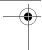
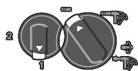
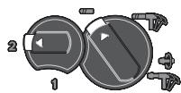
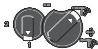
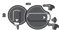
Setting the Operating Mode
The operating mode of the power tool is selected with the mode selector switch 12.
Note: Change the operating mode only when the machine is switched off! Otherwise, the machine can be damaged.
- To change the operating mode, push the release button 11 and turn the mode selector switch 12 to the requested position until it can be heard to latch.
PBH 2800 RE/PBH 2900 FRE/ PBH 3000 FRE Set
Position for drilling without impact in wood, metal, ceramic and plastic as well as for screwdriving and thread cutting
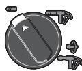
Position for hammer drilling in concrete or stone
Vario-Lock position for adjustment of the chiselling position
The mode selector switch 12 does not latch in this position.
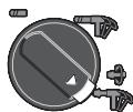
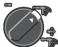
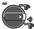
Position for chiselling
PBH 3000-2 FRE
For the operating modes hammer drilling, Vario-Lock and chiselling, the gear selector 13 must be set to 1st gear.
Position for drilling without impact (1st gear) in wood, metal, ceramic and plastic as well as for screwdriving and thread cutting
Position for drilling without impact (2nd gear) in wood, metal, ceramic and plastic
Position for hammer drilling in concrete or stone
Vario-Lock position for adjustment of the chiselling position
The mode selector switch 12 does not latch in this position.
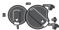
Position for chiselling
Reversing the Rotational Direction (see figure M)
The rotational direction switch 10 is used to reverse the rotational direction of the machine. However, this is not possible with the On/Off switch 8 actuated.
Right rotation: Push the rotational direction switch 10 rightward to the stop.
Left rotation: Push the rotational direction switch 10 leftward to the stop.
Set the direction of rotation for hammer drilling, drilling and chiselling always to right rotation.
Switching On and Off
- To start the machine, press the On/Off switch 8.
- To lock the On/Off switch 8, keep it pressed and additionally push the lock-on button 7.
- To switch off the machine, release the On/Off switch 8. When the On/Off switch 8 is locked, press it first and then release it.
Setting the Speed/Impact Rate
The speed/impact rate of the switched on power tool can be variably adjusted, depending on how far the On/Off switch 8 is pressed.
Light pressure on the On/Off switch 8 results in low speed/impact rate. Further pressure on the switch increases the speed/impact rate.
Preselecting the Speed/Impact Frequency
The required speed can be preselected with the thumbwheel 9 (also while running).
Due to the limitation, the On/Off switch 8 can only be pulled through to the preset limit.
Gear Selection, Mechanical (PBH 3000-2 FRE)
Two speed ranges can be preselected with the gear selector 13.
1st gear:
Low speed range; for hammer drilling, chiselling,drilling with large drilling diameter,screwdriving and thread cutting.
2nd gear:
High speed range; for drilling with small drilling diameter.
- To change gear, push the release button 11 on the mode selector switch 12 and turn the mode selector switch to the "drilling" position. Then push the release button 14 on the gear selector 13 and turn the gear selector to 2nd gear.
Note: The mode selector switch 12 may only be turned when the machine is switched off. The machine should also be switched off when turning the gear selector 13.
Hammer drilling and chiselling is possible only in 1st gear. In these operating modes, the special shape of the gear selector 13 and mode selector switch 12 do not allow switching to 2nd gear.
Before changing the operating mode from drilling to hammer drilling, Vario-Lock or chiselling, the gear selector 13 must be set back to 1st gear.
Safety Clutch
If the tool insert becomes caught or jammed, the drive to the drill spindle is interrupted. Because of the forces that occur, always hold the power tool firmly with both hands and provide for a secure stance.
If the power tool jams, switch the machine off and loosen the tool insert. When switching the machine on with the drilling tool jammed, high reaction torques can occur.
Working Advice
Rotation Direction for Chiselling
For chiselling, always set the rotation direction to right rotation. This prevents increased wear of the carbon brushes.
Changing the Chiselling Position (Vario-Lock)
The chisel can be locked in 36 positions. In this manner, the optimum working position can be set for each application.
- Insert the chisel into the tool holder.
- Turn the mode selector switch 12 to the "Vario-Lock" position (see "Setting the Operating Mode", page 27).
- Turn the tool holder to the desired chiselling position.
- Turn the mode selector switch 12 to the "chiselling" position. The tool holder is now locked.
- For chiselling, set the rotation direction to right rotation.
Inserting Screwdriver Bits (see figure N)
Apply the power tool to the screw/nut only when it is switched off. Rotating tool inserts can slip off.
To work with screwdriver bits, a universal bit holder 33 with SDS-plus shank (accessory) is required.
Clean the shank end of the adapter shank and apply a light coat of grease.
- Insert the universal bit holder with a turning motion into the tool holder until it automatically locks.
- Check the locking effect by pulling the universal bit holder.
- Insert a screwdriver bit into the universal bit holder. Use only screwdriver bits that match the screw head.
- To remove the universal bit holder, pull the locking sleeve 5 toward the rear and remove the universal bit holder 33 out of the tool holder.
Maintenance and Service
Maintenance and Cleaning
Before any work on the machine itself, pull the mains plug.
For safe and proper working, always keep the machine and ventilation slots clean.
A damaged dust protection cap should be changed immediately. We recommend having this carried out by an after-sales service.
Clean the tool holder 3 each time after using.
If the machine should fail despite the care taken in manufacturing and testing procedures, repair should be carried out by an after-sales service centre for Bosch power tools.
In all correspondence and spare parts order, please always include the 10-digit article number given on the type plate of the machine.
After-sales Service and Customer Assistance
Our after-sales service responds to your questions concerning maintenance and repair of your product as well as spare parts. Exploded views and information on spare parts can also be found under:
www.bosch-pt.com
Our customer service representatives can answer your questions concerning possible applications and adjustment of products and accessories.
Great Britain
Robert Bosch Ltd. (B.S.C.)
P.O.Box 98
Broadwater Park
North Orbital Road
Denham
Uxbridge
UB95HJ
Tel. Service: +44 (0844) 736 0109
Fax: +44 (0844) 736 0146
E-Mail: boschservicecentre@bosch.com
Ireland
Origo Ltd.
Unit 23 Magna Drive
Magna Business Park
City West
Dublin 24
Tel. Service: +353 (01) 466 67 00
Fax: +353 (01) 466 68 88

30 | English
Australia, New Zealand and Pacific Islands
Robert Bosch Australia Pty. Ltd.
Power Tools
Locked Bag 66
Clayton South VIC 3169
Customer Contact Center
Inside Australia:
Phone: +61 (01300) 307 044
Fax: +61 (01300) 307 045
Inside New Zealand:
Phone: +64 (0800) 543 353
Fax: +64 (0800) 428 570
Outside AU and NZ:
Phone: +61 (03) 9541 5555
www.bosch.com.au
Republic of South Africa
Customer service
Hotline: +27 (011) 6519600
Gauteng - BSC Service Centre
35 Roper Street, New Centre
Johannesburg
Tel.: +27 (011) 493 93 75
Fax: +27 (011) 4930126
E-Mail: bsctools@icon.co.za
KZN - BSC Service Centre
Unit E, Almar Centre
143 Crompton Street
Pinetown
Tel.: +27 (031) 7 01 21 20
Fax: +27 (031) 7 01 24 46
E-Mail: bsc.dur@za.bosch.com
Western Cape - BSC Service Centre
Democracy Way, Prosperity Park
Milnerton
Tel.: +27 (021) 551 25 77
Fax: +27 (021) 5513223
E-Mail: bsc@zsd.co.za
Bosch Headquarters
Midrand, Gauteng
Tel.: +27 (011) 6519600
Fax: +27 (011) 6519880
E-Mail: rbsa-hq.pts@za.bosch.com
Disposal
The machine, accessories and packaging should be sorted for environmental-friendly recycling.
Only for EC countries:
Do not dispose of power tools into household waste!
According the European Guideline 2002/96/EC for Waste Electrical and Electronic Equipment and its implementation into national
right, power tools that are no longer usable must be collected separately and disposed of in an environmentally correct manner.
Subject to change without notice.
Dr. Egbert Schneider Senior Vice President Engineering
Dr. Eckerhard Strötgen
Head of Product Certification
Robert Bosch (France) S.A.S.
ServiceAprès-VenteElectroportatif 126,rue de Stalingrad
93705 DRANCY Cedex
Tel.: +33 (0) 143 11 90 06
Fax: +33 (0) 143 11 90 33
E-Mail:
sav.outillage-electroportatif@fr.bosch.com
Dr. Egbert Schneider Senior Vice President Engineering
Dr. Eckerhard Strötgen
Head of Product Certification
ppa. Maee i.v. Nooey
Robert Bosch GmbH, Power Tools Division
D-70745 Leinfelden-Echterdingen
Leinfelden, 29.03.2007
Montaje
(PBH 2900 FRE/PBH 3000 FRE Set/
PBH 3000-2 FRE) (ver figura J)
Dr. Egbert Schneider Senior Vice President Engineering
Dr. Eckerhard Strötgen
Head of Product Certification


Robert Bosch GmbH, Power Tools Division
D-70745 Leinfelden-Echterdingen
Dr. Egbert Schneider Senior Vice President Engineering
Dr. Eckerhard Strötgen
Head of Product Certification


Robert Bosch GmbH, Power Tools Division
D-70745 Leinfelden-Echterdingen
Leinfelden, 29.03.2007


74 | Italiano
Dati tecnici
Dr. Egbert Schneider Senior Vice President Engineering
Dr. Eckerhard Strötgen
Head of Product
Certification

Robert Bosch GmbH, Power Tools Division
D-70745 Leinfelden-Echterdingen
Senior Vice President
Head of Product
Engineering
Certification
ppa. Maee i.v. Nooey
Robert Bosch GmbH, Power Tools Division
D-70745 Leinfelden-Echterdingen
Bosch Service Center
Telegrafvej 3
2750 Ballerup
Tel. Service Center: +45 (4489) 8855
Fax: +45 (4489) 87 55
E-Mail: vaerktoej@dk.bosch.com
Bortskaffelse
Dr. Egbert Schneider Senior Vice President Engineering
Dr. Eckerhard Strötgen
Head of Product Certification

Robert Bosch GmbH, Power Tools Division
D-70745 Leinfelden-Echterdingen
Leinfelden, 29.03.2007
Montage
Bosch Service Center
Telegrafvej 3
2750 Ballerup
Danmark
Tel.: +46 (020) 41 44 55
Fax: +46 (011) 187691
Avfallshantering
Dr. Egbert Schneider Senior Vice President Engineering
Dr. Eckerhard Strötgen
Head of Product Certification

Robert Bosch GmbH, Power Tools Division D-70745 Leinfelden-Echterdingen Leinfelden,29.03.2007
Montering
Senior Vice President
Head of Product
Engineering
Certification
ppa. Maee i.v. Nogcu
Robert Bosch GmbH, Power Tools Division
D-70745 Leinfelden-Echterdingen
Dr. Egbert Schneider
Dr. Eckerhard Ströttgen
Senior Vice President
Head of Product
Engineering
Certification

Robert Bosch GmbH, Power Tools Division D-70745 Leinfelden-Echterdingen Leinfelden,29.03.2007
Euvaopoloynon
ByaTeToPc ano TnV npizpiv ano onoiadnote epyaia oTo nlektpiko epyaieio.
TpOo0eTn AaBn
Xpoupoite to nEeptko epyaieo navtoe me ouvapoooynevtnpvnoaetn a 1 7
Tia to trpunmae Kpuoon kai yia to kaalemuopa Xpeiaeepyaleia SDS-plus ta onoi tonoetouvtai oto took SDS.
Tia trpunma xwpic kpoon o Eulaa, metalaa ka e Kepaikakai naotikauika kaowc kai yia Bldwa kai yia avoiyma onieipomegaatwv xnoioo niouvtai epyaoleia xwpic SDS-plus (n.x. tpu navia μe kuivdpiko stelexoc). Tia ta epyaoleia auta xpeiaote eva taxutok, avaloya, eva ypavazwtook.
PBH 3000-2 FRE: To taok SDS-plus 2 miopei va avtikataathetai ekoala e to tauxook 1 nou nepiexytal otuakeuaoaia.
AvtukatadotaoTou T0ok (PBH 2800 RE/ PBH 2900 FRE/PBH 3000 FRE Set)
Dr. Egbert Schneider Senior Vice President Engineering
Dr. Eckerhard Strötgen
Head of Product Certification


Robert Bosch GmbH, Power Tools Division D-70745 Leinfelden-Echterdingen Leinfelden,29.03.2007


152 | Türçce
Teknik veriler
| Kırkıneli PBH ... | 2800 RE | 2900 FRE | 3000 FRE Set | 3000-2 FRE |
| Ürün kodu | 3 603 C93 0.. | 3 603 C93 1.. | 3 603 C93 2.. | 3 603 C94 2.. |
| Devir saymiş kontrolü | ● | ● | ● | ● |
| Dönme stobu | ● | ● | ● | ● |
| Saq/ soldecess | ● | ● | ● | ● |
| Değiştilire bilir mandren | - | - | - | ● |
| Teslimat kapsamı - Anahtarsüz uz takma mandreni | - | ● | ● | ● |
| Giriç Güçü | W | 720 | 730 | 750 |
| Anma devir saychestra darbe saymiş | dev/dak | 4000 | 4000 | 4000 |
| Tek darbe kuveti | J | 0-2,6 | 0-2,7 | 0-2,8 |
| Devir saymiş | dev/dak | 1100 | 1100 | 1100 |
| Boştaki devir saychestra | dev/dak | 0-1450 | 0-1450 | 0-1450 |
| - 1. Vites | dev/dak | - | - | 0-3000 |
| - 2. Vites | dev/dak | SDS-plus | SDS-plus | SDS-plus |
| Uç kovani | ||||
| Mil boynu�能i | mm | 43 | 43 | 43 |
| Maksimum delme�能i: - Beton | mm | 26 | 26 | 26 |
| - Duvar (buat uzclarela) | mm | 68 | 68 | 68 |
| - Çelik | mm | 13 | 13 | 13 |
| - Ahşap | mm | 30 | 30 | 30 |
| Ağırkıngı EPTA-Procedure 01/2003'e[gre | kg | 3,0 | 3,0 | 3,0 |
| Koruma sinificant | 回/II | 回/II | 回/II |
Bosch San. ve Tic. A.S.
Ahi Evran Cad. No:1 Kat:22
Polaris Plaza
80670 Maslak/Istanbul
Müsteri Danismani: +90 (0212) 335 06 66
Müsteri Servis Hatti: +90 (0212) 335 07 52
Tasfiye
- PBH
- BOSCH
- Montage
- General Power Tool SafetyWarnings
- WARNING
- Save all warnings and instructions for future reference.
- 1) Work area safety
- 2) Electrical safety
- 3) Personal safety
- 4) Power tool use and care
- 5) Service
- Hammer SafetyWarnings
- Functional Description
- Intended Use
- Product Features
- | English
- Noise/Vibration Information
- Wear hearing protection!
- Declaration of Conformity C
- | English
- Assembly
- Auxiliary Handle
- Rotating the Auxiliary Handle (see figure A)
- Adjusting the Drilling Depth (see figure B)
- Selecting Drill Chucks and Tools
- Replacing the Drill Chuck (PBH 2800 RE/ PBH 2900 FRE/ PBH 3000 FRE Set)
- Mounting the Key Type Drill Chuck (Accessory) (PBH 2800 RE) (see figure C)
- Inserting the Key Type Drill Chuck or the Keyless Chuck (see figure D)
- Removing the Key Type Drill Chuck or the Keyless Chuck
- Removing/Inserting the Quick Change Chuck (PBH 3000-2 FRE)
- Removing the Quick Change Chuck (see figure E)
- Inserting the Quick Change Chuck (see figure F)
- Changing the Tool
- Inserting SDS-plus Drilling Tools (see figure G)
- Removing SDS-plus Drilling Tools (see figure H)
- Inserting Drilling Tools without SDS-plus into the Key Type Drill Chuck (PBH 2800 RE)
- Removing Drilling Tools without SDS-plus from the Key Type Drill Chuck (PBH 2800 RE)
- Inserting Drilling Tools without SDS-plus into the Keyless Chuck (PBH 2900 FRE/PBH 3000 FRE Set/ PBH 3000-2 FRE) (see figure I)
- | English
- Removing Drilling Tools without SDS-plus from the Keyless Chuck (PBH 2900 FRE/PBH 3000 FRE Set/ PBH 3000-2 FRE) (see figure J)
- Dust Extraction with the Dust Extraction Attachment (Accessory)
- Mounting the Dust Extraction Attachment (see figure K)
- Adjusting the Drilling Depth on the Dust Extraction Attachment (see figure L)
- Operation
- Starting Operation
- Setting the Operating Mode
- PBH 2800 RE/PBH 2900 FRE/ PBH 3000 FRE Set
- Position for chiselling
- PBH 3000-2 FRE
- Reversing the Rotational Direction (see figure M)
- Switching On and Off
- Setting the Speed/Impact Rate
- Preselecting the Speed/Impact Frequency
- Gear Selection, Mechanical (PBH 3000-2 FRE)
- 1st gear:
- 2nd gear:
- Safety Clutch
- Working Advice
- Rotation Direction for Chiselling
- Changing the Chiselling Position (Vario-Lock)
- Inserting Screwdriver Bits (see figure N)
- Maintenance and Service
- Maintenance and Cleaning
- After-sales Service and Customer Assistance
- www.bosch-pt.com
- Great Britain
- Ireland
- Australia, New Zealand and Pacific Islands
- Republic of South Africa
- Customer service
- Gauteng - BSC Service Centre
- KZN - BSC Service Centre
- Western Cape - BSC Service Centre
- Bosch Headquarters
- Disposal
- Only for EC countries:
- Montaje
- (PBH 2900 FRE/PBH 3000 FRE Set/
- PBH 3000-2 FRE) (ver figura J)
- Bortskaffelse
- Avfallshantering
- Montering
- Euvaopoloynon
- TpOo0eTn AaBn
- AvtukatadotaoTou T0ok (PBH 2800 RE/ PBH 2900 FRE/PBH 3000 FRE Set)
- Tasfiye
Brand : BOSCH
Model : PBH 2800 RE
Category : Rotary hammer