
PBH 2000 RE - Rotary hammer BOSCH - Free user manual and instructions
Find the device manual for free PBH 2000 RE BOSCH in PDF.
| Product type | Hammer drill (perforator) |
| Brand | BOSCH |
| Model | PBH 2000 RE |
| Rated power input | 550 W |
| Power output | 270 W |
| No-load impact rate | 0 – 5800 impacts/min |
| Impact energy | 1.5 J |
| Rated speed | 0 – 2300 rpm |
| Tool holder | SDS‑plus |
| Max. drilling diameter (concrete) | 20 mm |
| Max. drilling diameter (steel) | 13 mm |
| Max. drilling diameter (wood) | 30 mm |
| Weight (according to EPTA 01/2003) | 2.2 kg |
| Protection class | II (double insulation) |
| Power supply | Mains 230/240 V ~, 50 Hz |
| Sound pressure level (LpA) | 88 dB(A) (K=3 dB) |
| Sound power level (LwA) | 99 dB(A) (K=3 dB) |
| Vibration (hammer drilling) | ah = 11 m/s² (K=1.5 m/s²) |
| Vibration (chiseling) | ah = 9 m/s² (K=1.5 m/s²) |
| Operating modes | Hammer drilling, drilling without impact, chiseling, Vario‑Lock |
| Additional functions | Electronic speed control, right/left rotation, overload clutch, rotation stop |
| Additional handle | Yes, adjustable |
| Depth stop | Integrated, adjustable |
| Maintenance | Clean the ventilation slots and tool holder after each use. Replace damaged dust cap. |
| Safety | Wear hearing protection, safety glasses. Use the additional handle. Disconnect before any adjustment. |
| Spare parts and repairability | Spare parts available via Bosch after-sales service. Repairs by an authorized professional. |
Frequently Asked Questions - PBH 2000 RE BOSCH
User questions about PBH 2000 RE BOSCH
0 question about this device. Answer the ones you know or ask your own.
Ask a new question about this device
Download the instructions for your Rotary hammer in PDF format for free! Find your manual PBH 2000 RE - BOSCH and take your electronic device back in hand. On this page are published all the documents necessary for the use of your device. PBH 2000 RE by BOSCH.
USER MANUAL PBH 2000 RE BOSCH
Power Tools Division
70745 Leinfelden-Echterdingen
www.bosch-pt.com
1 619 929 764 (2007.09) T / 125 WEU
PBH
2000 RE | 2000 SRE

BOSCH
Senior Vice President
Head of Product
Engineering
Certification


24.07.2007, Robert Bosch GmbH, Power Tools Division D-70745 Leinfelden-Echterdingen
Montage
General Power Tool SafetyWarnings
WARNING
Read all safety warnings and all instructions. Failure to follow the
warnings and instructions may result in electric shock, fire and/or serious injury.
Save all warnings and instructions for future reference.
The term "power tool" in the warnings refers to your mains-operated (corded) power tool or battery-operated (cordless) power tool.
1) Work area safety
a) Keep work area clean and well lit. Cluttered or dark areas invite accidents.
b) Do not operate power tools in explosive atmospheres, such as in the presence of flammable liquids, gases or dust. Power tools create sparks which may ignite the dust or fumes.
c) Keep children and bystanders away while operating a power tool. Distractions can cause you to lose control.
2) Electrical safety
a) Power tool plugs must match the outlet. Never modify the plug in any way. Do not use any adapter plugs with earthed (grounded) power tools. Unmodified plugs and matching outlets will reduce risk of electric shock.
b) Avoid body contact with earthed or grounded surfaces, such as pipes, radiators, ranges and refrigerators. There is an increased risk of electric shock if your body is earthed or grounded.
c) Do not expose power tools to rain or wet conditions. Water entering a power tool will increase the risk of electric shock.
d) Do not abuse the cord. Never use the cord for carrying, pulling or unplugging the power tool. Keep cord away from heat, oil, sharp edges and moving parts. Damaged or entangled cords increase the risk of electric shock.
e) When operating a power tool outdoors, use an extension cord suitable for outdoor use. Use of a cord suitable for outdoor use reduces the risk of electric shock.
f) If operating a power tool in a damp location is unavoidable, use a residual current device (RCD) protected supply. Use of an RCD reduces the risk of electric shock.
3) Personal safety
a) Stay alert, watch what you are doing and use common sense when operating a power tool. Do not use a power tool while you are tired or under the influence of drugs, alcohol or medication. A moment of inattention while operating power tools may result in serious personal injury.
b) Use personal protective equipment. Always wear eye protection. Protective equipment such as dust mask, non-skid safety shoes, hard hat, or hearing protection used for appropriate conditions will reduce personal injuries.
c) Prevent unintentional starting. Ensure the switch is in the off-position before connecting to power source and/or battery pack, picking up or carrying the tool. Carrying power tools with your finger on the switch or energising power tools that have the switch on invites accidents.
d) Remove any adjusting key or wrench before turning the power tool on. A wrench or a key left attached to a rotating part of the power tool may result in personal injury.
e) Do not overreach. Keep proper footing and balance at all times. This enables better control of the power tool in unexpected situations.
f) Dress properly. Do not wear loose clothing or jewellery. Keep your hair, clothing and gloves away from moving parts. Loose clothes, jewellery or long hair can be caught in moving parts.
g) If devices are provided for the connection of dust extraction and collection facilities, ensure these are connected and properly used. Use of dust collection can reduce dust-related hazards.


4) Power tool use and care
a) Do not force the power tool. Use the correct power tool for your application. The correct power tool will do the job better and safer at the rate for which it was designed.
b) Do not use the power tool if the switch does not turn it on and off. Any power tool that cannot be controlled with the switch is dangerous and must be repaired.
c) Disconnect the plug from the power source and/or the battery pack from the power tool before making any adjustments, changing accessories, or storing power tools. Such preventive safety measures reduce the risk of starting the power tool accidentally.
d) Store idle power tools out of the reach of children and do not allow persons unfamiliar with the power tool or these instructions to operate the power tool. Power tools are dangerous in the hands of untrained users.
e) Maintain power tools. Check for misalignment or binding of moving parts, breakage of parts and any other condition that may affect the power tool's operation. If damaged, have the power tool repaired before use. Many accidents are caused by poorly maintained power tools.
f) Keep cutting tools sharp and clean. Properly maintained cutting tools with sharp cutting edges are less likely to bind and are easier to control.
g) Use the power tool, accessories and tool bits etc. in accordance with these instructions, taking into account the working conditions and the work to be performed. Use of the power tool for operations different from those intended could result in a hazardous situation.
5) Service
a) Have your power tool serviced by a qualified repair person using only identical replacement parts. This will ensure that the safety of the power tool is maintained.
Machine-specific SafetyWarnings
Wear hearing protection. Exposure to noise can cause hearing loss.
Always use the auxiliary handle supplied with the machine. Loss of control can cause personal injury.
- Use suitable detectors to determine if utility lines are hidden in the work area or call the local utility company for assistance. Contact with electric lines can lead to fire and electric shock. Damaging a gas line can lead to explosion. Penetrating a water line causes property damage or may cause an electric shock.
- When working with the machine, always hold it firmly with both hands and provide for a secure stance. The power tool is guided more secure with both hands.
- Secure the workpiece. A workpiece clamped with clamping devices or in a vice is held more secure than by hand.
Do not work materials containing asbestos. Asbestos is considered carcinogenic.
Take protective measures when dust can develop during working that is harmful to one's health, combustible or explosive. Example: Some dusts are regarded as carcinogenic. Wear a dust mask and work with dust/chip extraction when connectable.
- Keep your workplace clean. Blends of materials are particularly dangerous. Dust from light alloys can burn or explode.
Always wait until the machine has come to a complete stop before placing it down. The tool insert can jam and lead to loss of control over the power tool.
- Never use the machine with a damaged cable. Do not touch the damaged cable and pull the mains plug when the cable is damaged while working. Damaged cables increase the risk of an electric shock.


18 | English
Functional Description

Read all safety warnings and all instructions. Failure to follow the warnings and instructions may result in electric shock, fire and/or serious injury.
Intended Use
The machine is intended for hammer drilling in concrete, brick and stone, as well as for light chiselling work. It is also suitable for drilling without impact in wood, metal, ceramic and plastic. Machines with electronic control and right/left rotation are also suitable for screwdriving.
Product Features
The numbering of the product features refers to the illustration of the machine on the graphics page.
1 SDS-plus tool holder
2 Dust protection cap
3 Locking sleeve
4 Lock-on button for On/Off switch
5 On/Off switch
6 Rotational direction switch
7 Mode selector switch
8 Button for depth stop adjustment
9 Wing bolt for adjustment of auxiliary handle
10 Auxiliary handle
11 Depth stop
12 Key type drill chuck
13 Extraction sleeve of the dust extraction attachment
14 Clamping screw for the dust extraction attachment
15 Depth stop of the dust extraction attachment
16 Telescopic pipe of the dust extraction attachment
17 Wing bolt of the dust extraction attachment
18 Guide pipe of the dust extraction attachment
19 Universal bit holder with SDS-plus shank
*The accessories illustrated or described are not included as standard delivery.
Noise/Vibration Information
Measured values determined according to EN 60745.
Typically the A-weighted noise levels of the product are: Sound pressure level 88 dB(A); Sound power level 99 dB(A).
Uncertainty K = 3 dB.
Wear hearing protection!
Vibration total values (triax vector sum) determined according to EN 60745:
Hammer drilling into concrete: Vibration emission value a_h = 11 m/s^2 , Uncertainty K = 1.5 m/s^2 , Chiselling: Vibration emission value a_h = 9 m/s^2 , Uncertainty K = 1.5 m/s^2 .
The vibration emission level given in this information sheet has been measured in accordance with a standardised test given in EN 60745 and may be used to compare one tool with another. It may be used for a preliminary assessment of exposure.
The declared vibration emission level represents the main applications of the tool. However if the tool is used for different applications, with different accessories or poorly maintained, the vibration emission may differ. This may significantly increase the exposure level over the total working period.
An estimation of the level of exposure to vibration should also take into account the times when the tool is switched off or when it is running but not actually doing the job. This may significantly reduce the exposure level over the total working period.
Identify additional safety measures to protect the operator from the effects of vibration such as: maintain the tool and the accessories, keep the hands warm, organisation of work patterns.

Technical Data
| Rotary Hammer | PBH 2000 RE | PBH 2000 SRE | |
| Article number | 3 603 C44 3.. | 3 603 C44 3.. | |
| Speed control | ● | ● | |
| Stop rotation | ● | ● | |
| Right/left rotation | ● | ● | |
| Delivery Scope | |||
| - Key type drill chuck | - | ● | |
| Rated power input | W | 550 | 550 |
| Output power | W | 270 | 270 |
| Impact rate | bpm | 0-5800 | 0-5800 |
| Impact energy per stroke | J | 1.5 | 1.5 |
| Rated speed | rpm | 0-2300 | 0-2300 |
| Tool holder | SDS-plus | SDS-plus | |
| Spindle collar diameter | mm | 43 (Euro-Norm) | 43 (Euro-Norm) |
| Drilling diameter, max.: | |||
| - Concrete | mm | 20 | 20 |
| - Steel | mm | 13 | 13 |
| - Wood | mm | 30 | 30 |
| Weight according to EPTA-Procedure 01/2003 | kg | 2.2 | 2.2 |
| Protection class | ☐ / II | ☐ / II |
The values given are valid for nominal voltages [U] of 230/240 V. For lower voltage and models for specific countries, these values can vary.
Please observe the article number on the type plate of your machine. The trade names of the individual machines may vary.
Declaration of Conformity C
We declare under our sole responsibility that the product described under "Technical Data" is in conformity with the following standards or standardization documents: EN 60745 according to the provisions of the directives 2004/108/EC, 98/37/EC (until Dec. 28, 2009), 2006/42/EC (from Dec. 29, 2009 on).
Technical file at:
Robert Bosch GmbH, PT/ESC,
D-70745 Leinfelden-Echterdingen
Dr. Egbert Schneider
Dr. Eckerhard Strötgen
Senior Vice President
Head of Product
Engineering
Certification
ppa. Maee i.v. Nogcu
24.07.2007, Robert Bosch GmbH, Power Tools Division D-70745 Leinfelden-Echterdingen
20 | English
Assembly
Before any work on the machine itself, pull the mains plug.
Auxiliary Handle
Operate your machine only with the auxiliary handle 10.
Rotating the Auxiliary Handle (see figure A)
The auxiliary handle 10 can be set to any position for a secure and low-fatigue working posture.
Turn the wing bolt for adjustment of the auxiliary handle 9 in anticlockwise direction and set the auxiliary handle 10 to the required position. Then tighten the wing bolt 9 again in clockwise direction.
Adjusting the Drilling Depth (see figure B)
The required drilling depth X can be set with the depth stop 11.
Press the button for the depth stop adjustment 8 and insert the depth stop into the auxiliary handle 10.
The knurled surface of the depth stop 11 must face downward.
Insert the SDS-plus drilling tool to the stop into the SDS-plus tool holder 1. Otherwise, the movability of the SDS-plus drilling tool can lead to incorrect adjustment of the drilling depth.
Pull out the depth stop until the distance between the tip of the drill bit and the tip of the depth stop correspond with the desired drilling depth X .
Selecting Drill Chucks and Tools
For hammer drilling and chiselling, SDS-plus tools are required that are inserted in the SDS-plus drill chuck.
For drilling without impact in wood, metal, ceramic and plastic as well as for screwdriving, tools without SDS-plus are used (e.g., drills with cylindrical shank). For these tools, a keyless chuck or a key type drill chuck are required.
Changing the Key Type Drill Chuck
To work with tools without SDS-plus (e.g., drills with cylindrical shank), a suitable drill chuck must be mounted (key type drill chuck or keyless chuck, accessories).
Inserting the Key Type Drill Chuck (see figure C)
Clean the shank end of the adapter shank and apply a light coat of grease.
Insert the key type drill chuck with the adapter shank into the tool holder with a turning motion until it automatically locks.
Check the locking effect by pulling the key type drill chuck.
Removing the Key Type Drill Chuck
Push the locking sleeve 3 toward the rear and pull out the key type drill chuck 12.
Changing the Tool
The dust protection cap 2 largely prevents the entry of drilling dust into the tool holder during operation. When inserting the tool, take care that the dust protection cap 2 is not damaged.
A damaged dust protection cap should be changed immediately. We recommend having this carried out by an after-sales service.
Inserting SDS-plus Drilling Tools (see figure D)
The SDS-plus drill chuck allows for simple and convenient changing of drilling tools without the use of additional tools.
Clean and lightly grease the shank end of the tool. Insert the tool in a twisting manner into the tool holder until it latches itself.
Check the latching by pulling the tool.
As a requirement of the system, the SDS-plus drilling tool can move freely. This causes a certain radial run-out at no-load, which has no effect on the accuracy of the drill hole, as the drill bit centres itself upon drilling.
Removing SDS-plus Drilling Tools (see figure E)
Push back the locking sleeve 3 and remove the tool.


Inserting Drilling Tools without SDS-plus (see figure F)
Note: Do not use tools without SDS-plus for hammer drilling or chiselling! Tools without SDS-plus and their drill chucks are damaged by hammer drilling or chiselling.
Insert a key type drill chuck 12 (see "Changing the Key Type Drill Chuck", page 20).
Open the key type drill chuck 12 by turning until the tool can be inserted. Insert the tool.
Insert the chuck key into the corresponding holes of the key type drill chuck 12 and clamp the tool uniformly.
Turn the mode selector switch 7 to the "drilling" position.
Removing Drilling Tools without SDS-plus (see figure G)
Turn the sleeve of the key type drill chuck 12 with the drill chuck key in anticlockwise direction until the drilling tool can be removed.
Dust Extraction with the Dust Extraction Attachment (Accessory)
Mounting the Dust Extraction Attachment (see figure H)
For dust extraction, the dust extraction attachment (accessory) is required. When drilling, the dust extraction attachment retracts so that the attachment head is always close to the surface at the drill hole.
Press the button for depth stop adjustment 8 and remove the depth stop 11. Press button 8 again and insert the dust extraction attachment into the auxiliary handle 10 from the front.
Connect an extraction hose (diameter 19 mm, accessory) to the extraction sleeve 13 of the dust extraction attachment.
The vacuum cleaner must be suitable for the material being worked.
When vacuuming dry dust that is especially detrimental to health or carcinogenic, use a special vacuum cleaner.
Adjusting the Drilling Depth on the Dust Extraction Attachment (see figure I)
The required drilling depth X can also be adjusted when the dust extraction attachment is mounted.
Insert the SDS-plus drilling tool to the stop into the SDS-plus tool holder 1. Otherwise, the movability of the SDS-plus drilling tool can lead to incorrect adjustment of the drilling depth.
Loosen the wing bolt 17 on the dust extraction attachment.
Without switching the power tool on, apply it firmly to the drilling location. The SDS-plus drilling tool must face against the surface.
Position the the guide pipe 18 of the dust extraction attachment in its holding fixture in such a manner that the head of the dust extraction attachment faces against the surface to be drilled. Do not slide the guide pipe 18 further over the telescopic pipe 16 of the dust extraction attachment than required, so that as much as possible of the scale 16 on the telescopic pipe remains visible.
Retighten the wing bolt 17 again. Loosen the clamping screw 14 on the depth stop of the dust extraction attachment.
Move the depth stop 15 on the telescopic pipe 16 in such a manner that the clearance X shown in the figure corresponds with the required drilling depth.
Tighten the clamping screw 14 in this position.
22 | English
Operation
Starting Operation
Observe correct mains voltage! The voltage of the power source must agree with the voltage specified on the nameplate of the machine. Power tools marked with 230V can also be operated with 220V .
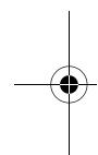
Setting the Operating Mode
The operating mode of the power tool is selected with the mode selector switch 7.
Note: Change the operating mode only when the machine is switched off! Otherwise, the machine can be damaged.
Turn the mode selector switch 7 to the desired position until it can be heard to latch.
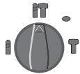
Position for hammer drilling in concrete or stone
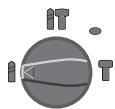
Position for drilling without impact in wood, metal, ceramic and plastic as well as for screwdriving
Vario-Lock position for adjustment of the chiselling position
The mode selector switch 7 does not latch in this position.
Position for chiselling
Reversing the Rotational Direction (see figure J)
The rotational direction switch 6 is used to reverse the rotational direction of the machine. However, this is not possible with the On/Off switch 5 actuated.
Right rotation: Push the rotational direction switch 6 rightward to the stop.
Left rotation: Push the rotational direction switch 6 leftward to the stop.
Set the direction of rotation for hammer drilling, drilling and chiselling always to right rotation.
Switching On and Off
To start the machine, press the On/Off switch 5.
To lock the On/Off switch, keep it pressed and additionally push the lock-on button 4.
To switch off the machine, release the On/Off switch 5. When the On/Off switch 5 is locked, press it first and then release it.
Setting the Speed/Impact Rate
The speed/impact rate of the switched on power tool can be variably adjusted, depending on how far the On/Off switch 5 is pressed.
Light pressure on the On/Off switch 5 results in low speed/impact rate. Further pressure on the switch increases the speed/impact rate.
Safety Clutch
If the tool insert becomes caught or jammed, the drive to the drill spindle is interrupted. Because of the forces that occur, always hold the power tool firmly with both hands and provide for a secure stance.
If the power tool jams, switch the machine off and loosen the tool insert. When switching the machine on with the drilling tool jammed, high reaction torques can occur.
Working Advice
Changing the Chiselling Position (Vario-Lock)
The chisel can be locked in 36 positions. In this manner, the optimum working position can be set for each application.
Insert the chisel into the tool holder.
Turn the mode selector switch 7 to the "VarioLock" position (see "Setting the Operating Mode", page 22).
Turn the tool holder to the desired chiselling position.
Turn the mode selector switch 7 to the "chiselling" position. The tool holder is now locked.
For chiselling, set the rotation direction to right rotation.
Inserting Screwdriver Bits (see figure K)
Apply the power tool to the screw/nut only when it is switched off. Rotating tool inserts can slip off.
To work with screwdriver bits, a universal bit holder 19 with SDS-plus shank (accessory) is required.
Clean the shank end of the adapter shank and apply a light coat of grease.
Insert the universal bit holder with a turning motion into the tool holder until it automatically locks.
Check the locking effect by pulling the universal bit holder.
Insert a screwdriver bit into the universal bit holder. Use only screwdriver bits that match the screw head.
To remove the universal bit holder, pull the locking sleeve 3 toward the rear and remove the universal bit holder 19 out of the tool holder.
Maintenance and Service
Maintenance and Cleaning
Before any work on the machine itself, pull the mains plug.
For safe and proper working, always keep the machine and ventilation slots clean.
A damaged dust protection cap should be changed immediately. We recommend having this carried out by an after-sales service.
Clean the tool holder 1 each time after using.
WARNING! Important instructions for connecting a new 3-pin plug to the 2-wire cable.
The wires in the cable are coloured according to the following code:

Do not connect the blue or brown wire to the earth terminal of the plug.
Important: If for any reason the moulded plug is removed from the cable of this power tool, it must be disposed of safely.
If the machine should fail despite the care taken in manufacturing and testing procedures, repair should be carried out by an after-sales service centre for Bosch power tools.
In all correspondence and spare parts order, please always include the 10-digit article number given on the type plate of the machine.

24 | English
After-sales service and customer assistance
Our after-sales service responds to your questions concerning maintenance and repair of your product as well as spare parts. Exploded views and information on spare parts can also be found under:
www.bosch-pt.com
Our customer consultants answer your questions concerning best buy, application and adjustment of products and accessories.
Great Britain
Robert Bosch Ltd. (B.S.C.)
P.O.Box 98
Broadwater Park
North Orbital Road
Denham
Uxbridge
UB95HJ
Tel. Service: +44 (0844) 736 0109
Fax:+44(0844)7360146
Australia, New Zealand and Pacific Islands
Robert Bosch Australia Pty. Ltd.
Power Tools
Locked Bag 66
Clayton South VIC 3169
Customer Contact Center
Inside Australia:
Phone: +61 (01300) 307 044
Fax: +61 (01300) 307 045
Inside New Zealand:
Phone: +64 (0800) 543 353
Fax: +64 (0800) 428 570
Outside AU and NZ:
Phone: +61 (03) 9541 5555
www.bosch.com.au
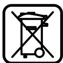
Disposal
The machine, accessories and packaging should be sorted for environmental-friendly recycling.
Only for EC countries:
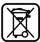
Do not dispose of power tools into household waste!
According the European Guideline 2002/96/EC for Waste Electrical and Electronic Equipment and its implementation into national right,
power tools that are no longer usable must be collected separately and disposed of in an environmentally correct manner.
Subject to change without notice.


Senior Vice President
Head of Product
Engineering
Certification
Robert Bosch (France) S.A.S.
Senior Vice President
Head of Product
Engineering
Certification
Senior Vice President
Head of Product
Engineering
Certification
ppa. Maee i.v. Nogcu
24.07.2007, Robert Bosch GmbH, Power Tools Division D-70745 Leinfelden-Echterdingen

50 | Portugues
Montagem
- Antes de todoseworkos na ferramenta electricadeferapeuxarafichadedatomada.
Punho adicional
Senior Vice President
Head of Product
Engineering
Certification
Senior Vice President
Head of Product
Engineering
Certification
paa.
i.v. Moju
24.07.2007, Robert Bosch GmbH, Power Tools Division D-70745 Leinfelden-Echterdingen

70 | Nederlands
Montage
Senior Vice President
Head of Product
Engineering
Certification
ppa. Maee i.v. Nogcu
24.07.2007, Robert Bosch GmbH, Power Tools Division D-70745 Leinfelden-Echterdingen
Montering
Bosch Service Center
Telegrafvej 3
2750 Ballerup
Tel. Service Center: +45 (04489) 8855
Fax: +45 (04489) 87 55
E-Mail: vaerktoej@dk.bosch.com
Bortskaffelse
El-vaerktoj, tilbehor og emballage skal genbruges pa en miljovenlig maje.
Dr. Egbert Schneider
Dr. Eckerhard Ströttgen
Senior Vice President
Head of Product
Engineering
Certification
ppa. 11. i.v. uogcu
24.07.2007, Robert Bosch GmbH, Power Tools Division D-70745 Leinfelden-Echterdingen
86 | Svenska
Montage
Dra stickproppen ur nätuttaget innan arbeiten utfors på elverktyget.
Stödhandtag
Endast for EU-lander:
Senior Vice President
Head of Product
Engineering
Certification
Senior Vice President
Head of Product
Engineering
Certification
Senior Vice President
Head of Product
Engineering
Certification
ppa. Maee i.v. Nogcu
24.07.2007, Robert Bosch GmbH, Power Tools Division D-70745 Leinfelden-Echterdingen
Euvaρολόγησ
Bydcto ano tvnpica npiv ano onoi- hnote epyaia oTo nAekptikO epyaleio.
Piopo0eTn AaBn
Xpoupoite to nEeKpiko epyaieo navtoe e ouvapmooynveyn tv npooetn 10.
MetakivnTnc npo0eTnc laBic (βλeNE eikova A)
H npo0etn laa 10 mopei va puthetai oe onoiabhote oen enioueite yia va mopoeete etai va epyaote i eva kal avanautika.
TupioTe Tn Bida lo yia tn puo0iOn TnC npoo0eTnc AaBc9 9 e opa avriOeTn Twv 6eikTwv Tou poLoayou' kai puOoiTe Tnv npOo0eTn laBn 10 Otnv enIoumnt thcAn. AkoauOwC ophiEte Tn Bida lo 9 yupizovtac Tnv m opoLoayiak fopá.
Pouan aouc npunmuoc (Bene eikova B)
Me tov odnyo a ouc 11 mopoite va pu muiete to eti u nto a oc trpuinmuatox.
Pntnto nAnkpto puOmuoc tou baouc tpuu maoc 8 kal eayete tov odnyo baouc otnv npooetn laBn 10.
OlaulakwoeiocTovo8nyoBa0ouc11 npeneva 6eixvouv npoc ta kAtw.
to epyaleio SDS-plus tepma otyn uno- doxn epyaleiou SDS-plus 1. diaopopeikac n kivntikotnta tou epyaleiou SDS-plus mnopei va obnynoe ie aaoocpuoan tou baooctpumnatoc.
TpaBnEte Tov obnyo baOouc npoc ta eEw, mExpi n anoTaon avapeo aTnv auXmuTu prunaviou Ka Tnu aixmu Tou obnyou BaOouc va avtanokpivetai oTo emuumto baooc trunmuatox.
Enuoy Took kal epyaiewv
Tia to Tpuunmae Kpouan kal yia to kaLemua Xpeiaeepvaaleia SDS-plus ta onoia tonoetouvta oTo Took SDS.
Tia Tpuinma Xwipc Kpouon oE Euλa, MaTaλla Ka iOe Kepaikai Nlaotika uikak aKoC kai yia Bldomegaata npenei va xpoaiomoiite epyaleia Xwipc SDS-plus (π.x. Tpuinavia μe kuivdpiko OTelexoc).Tia Ta epyaleia auta xpeiazeote n eva taxutook n eva ypavazwto took.
Apaipean tou ypavaawou took
to Kekuoc mavdaawc 3 npoc ta niow kai apaipoeTe to ypavaztoTook 12.
AvtkaataoTaon eXapntmuatoc
To kαλuμma npoσtaiaic ano oκovn 2 εμntobiciεi ikavonoiŋtikātn δieiaδuon oκovnc tpuñmuatoC Θnv unödoxη εργaileiou katātn δiapkeia tcλeitoupyiac. Oτav toπoθeteite to eργaileio npénei va npoεxe, va μην unootei βλβn to kαλuμma npoσtaiaic ano oκovn 2.
Eva xaagveo kalaumpa npoataiac ano oKovn npenei va avtikaotatala eowc. Saocoubetaoueoume, n avtikatotaon va diExyetai ano to Service.
Toonotonepyaaleiou SDS-plus (βλeεικóva D)
Me to taok SDS-plus mnpoeite va aalaaeteto tonoetnmuvo epyaieio anka kalaveta, xwpic va xpoiouoiote aaiaepyaieia.
Dr. Egbert Schneider Senior Vice President Engineering
Dr. Eckerhard Strötgen
Head of Product Certification

24.07.2007, Robert Bosch GmbH, Power Tools Division D-70745 Leinfelden-Echterdingen
Montaj
Bosch San. ve Tic. A.S.
Ahi Evran Cad. No:1 Kat:22
Polaris Plaza
80670 Maslak/Istanbul
Müsteri Danisman: +90 (0212) 335 06 66
Müsteri Servis Hatti: +90 (0212) 335 07 52