USER MANUAL 1923H MAKITA
Explanation of general view
1 Bolt
2 Drum
3 Planer blade
4 Drum cover
5 Adjust plate
6 Blade edge
7 Screws
8 Heel
9 Back side of gauge base
10 Inside edge of gauge plate
11 Gauge plate
12 Gauge base
13 Pan head screw
14 Planer blade locating lugs
15 Heel of adjust plate
16 Set plate
17 Inside flank of gauge plate
18 Mini planer blade
19 Hex. flange head bolt
20 Groove
21 Not used
22 Not used
23 Not used
24 Not used
25 Knob
26 Switch trigger
27 Lock button
28 Lock-off button
29 Start
30 End
31 Blade edge
32 Cutting line
33 Screw
34 Edge fence
35 "V" groove
36 Front base
37 Align the "V" groove with the edge of the workpiece.
38 Screw
39 Nozzle assembly
40 Sharpening holder
41 Wing nut
42 Blade (A)
43 Blade (B)
44 Side (C)
45 Side (D)
46 Screwdriver
47 Nozzle
48 Vacuum cleaner
49 Limit mark
50 Rear cover
51 Carbon brushes
SPECIFICATIONS
Model 1923H
Planing width 82 mm
Planing depth 3.5 mm
Shiplapping depth 23 mm
No load speed (^-1) 16,000
Overall length 293 mm
Net weight 3.5 kg
- Due to the continuing program of research and development, the specifications herein are subject to change without prior notice.
Note: Specifications may differ from country to country.
Power supply
The tool should be connected only to a power supply of the same voltage as indicated on the nameplate, and can only be operated on single-phase AC supply. They are double-insulated in accordance with European Standard and can, therefore, also be used from sockets without earth wire.
Safety hints
- For your own safety, please refer to enclosed Safety instructions.
- Please refer to the end of this manual for EC-Declaration, Noise and Vibration.
These symbols mean:
Read instruction manual.
DOUBLE INSULATION
ADDITIONAL SAFETY RULES
ENB045-2
- Rags, cloth, cord, string and the like should never be left around the work area.
- Avoid cutting nails. Inspect for and remove all nails from the workpiece before operation.
- Use only sharp blades. Handle the blades very carefully.
- Be sure the blade installation bolts are securely tightened before operation.
- Hold the tool firmly.
- Keep hands away from rotating parts.
- Before using the tool on an actual workpiece, let it run for a while. Watch for vibration or wobbling that could indicate poor installation or a poorly balanced blade.
- Make sure the blade is not contacting the workpiece before the switch is turned on.
- Wait until the blade attains full speed before cutting.
- Keep at least 200mm away from the tool at all times.
- Always switch off and wait for the blades to come to a complete stop before any adjusting.
- Never stick your finger into the chip chute. Chute may jam when cutting damp wood. Clean out chips with a stick.
- Do not leave the tool running. Operate the tool only when hand-held.
- When leaving the planer, switch off and set it with the front base up on a wooden block, so that the blades do not contact anything.
- Always change both blades or covers on the drum, otherwise the resulting imbalance will cause vibration and shorten tool life.
- Wait for complete run-down before putting the tool aside.
17.Use only Makita blades specified in this manual.
SAVE THESE INSTRUCTIONS.
OPERATING INSTRUCTIONS
Removing or installing planer blades
Important:
Always be sure that tool is switched off and unplugged before removing or installing the blade.
- Use the following planer blades.
Part Nos. 793004-6 793007-0 793322-2
P-04260 P04276 *P-04282
820044-1 820045-1 *820043-1
Blades with * mark are available in European countries only. Consult your dealer or the Makita Service Center when purchasing blades.
To remove the blades on the drum, unscrew the three installation bolts with the socket wrench. The drum cover comes off together with the blades.
To install the blades, first clean out all chips or foreign matter adhering to the drum or blades. Use blades of the same dimensions and weight, or drum oscillation/vibration will result, causing poor planing action and, eventually, tool breakdown.
Place the blade on the gauge base so that the blade edge is perfectly flush with the inside edge of the gauge plate. Place the adjust plate on the blade, then simply press in the heel of the adjust plate flush with the back side of the gauge base and tighten two screws on the adjust plate. Now slip the heel of the adjust plate into the drum groove, then fit the drum cover on it. Tighten the three installation bolts evenly and alternately with the socket wrench.
- Remove the existing blade, if the tool has been in use, carefully clean the drum surfaces and the drum cover. To remove the blades on the drum, unscrew the three installation bolts with the socket wrench. The drum cover comes off together with the blades.
-
To install the blades, loosely attach the adjust plate to the set plate with the pan head screws and set the mini planer blade on the gauge base so that the cutting edge of the blade is perfectly flush with the inside flank of the gauge plate.
-
Set the adjust plate/set plate on the gauge base so that the planer blade locating lugs on the set plate rest in the mini planer blade groove, then press in the heel of the adjust plate flush with the back side of the gauge base and tighten the pan head screws.
- It is important that the blade sits flush with the inside flank of the gauge plate, the planer blade locating lugs sit in the blade groove and the heel of the adjust plate is flush with the back side of the gauge base. Check this alignment carefully to ensure uniform cutting.
- Slip the heel of the adjust plate into the groove of the drum.
- Set the drum cover over the adjust plate/set plate and screw in the three hex flange head bolts so that a gap exists between the drum and the set plate to slide the mini planer blade into position. The blade will be positioned by the planer blade locating lugs on the set plate.
- The blade's lengthwise adjustment will need to be manually positioned so that the blade ends are clear and equidistant from the housing on one side and the metal bracket on the other.
- Tighten the three hex flange head bolts (with the socket wrench provided) and hand rotate the drum to check clearances between the blade ends and the tool body.
- Check the three hex flange head bolts for final tightness.
- Repeat procedures 1-9 for other blade.
For shiplapping (Fig. 11)
The blade edge should be made to protrude outside slightly (0.3mm - 0.6mm) . Otherwise, nicks and generally poor shiplapping results.
CAUTION:
Tighten the blade installation bolts carefully when attaching the blades to the tool. A loose installation bolt can be dangerous. Always check to see they are tightened securely.
For the correct planer blade setting
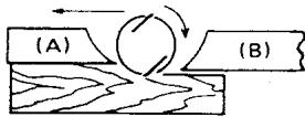
Your planing surface will end up rough and uneven, unless the blade is set properly and securely. The blade must be mounted so that the cutting edge is absolutely level, that is, parallel to the surface of the rear base. Below are some examples of proper and improper settings.
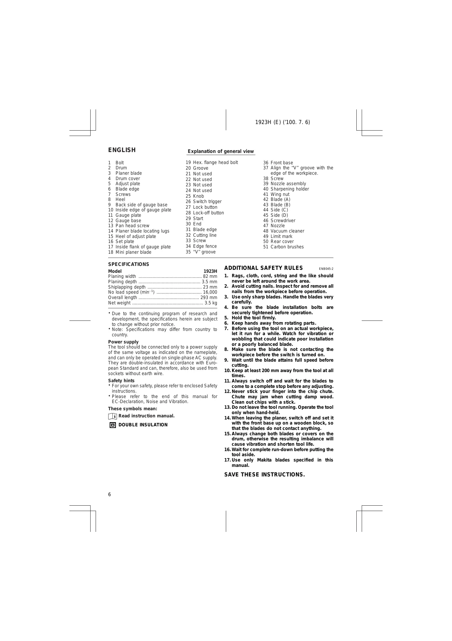
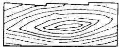
(A) Front base (Movable shoe)
(B) Rear base (Stationary shoe)
Correct setting

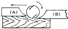
Although this side view cannot show it, the edges of the blades run perfectly parallel to the rear base surface.
Nicks in surface
Cause: One or both blades fails to have edge parallel to rear base line.
Gouging at start

Cause: One or both blade edges fails to protrude enough in relation to rear base line.
Gouging at end

Cause: One or both blade edges protrudes too far in relation to rear base line.
Adjusting the depth of cut (Fig. 12)
Depth of cut may be adjusted by simply turning the knob on the front of the tool.
Switch action
CAUTION:
Before plugging in the tool, always check to see that the switch trigger actuates properly and returns to the "OFF" position when released.
To start the tool, simply pull the trigger. Release the trigger to stop.
To start the tool, simply pull the trigger. Release the trigger to stop. For continuous operation, pull the trigger and then push in the lock button. To stop the tool from the locked position, pull the trigger fully, then release it.
To prevent the trigger from being accidentally pulled, a lock-off button is provided. To start the tool, press the lock-off button and pull the trigger. Release the trigger to stop.
Planing operation (Fig. 16)
First, rest the tool front base flat upon the workpiece surface without the blades making any contact. Switch on and wait until the blades attain full speed. Then move the tool gently forward. Apply pressure on the front of tool at the start of planing, and at the back at the end of planing. Planing will be easier if you incline the workpiece in stationary fashion, so that you can plane somewhat downhill.
The speed and depth of cut determine the kind of finish. The power planer keeps cutting at a speed that will not result in jamming by chips. For rough cutting, the depth of cut can be increased, while for a good finish you should reduce the depth of cut and advance the tool more slowly.
Shiplapping (Fig. 17, 18, 19 & 20)
To make a stepped cut as shown in Fig. 17, use the edge fence.
Draw a cutting line on the workpiece. Insert the edge fence into the hole in the front of the tool. Align the blade edge with the cutting line.
Adjust the edge fence until it comes in contact with the side of the workpiece, then secure it by tightening the screw.
You may wish to add to the length of the fence by attaching an extra piece of wood. Convenient holes are provided in the fence for this purpose, and also for attaching an extension guide (optional accessory).
NOTE:
When planing, move the tool with the edge fence flush with the side of the workpiece. Otherwise uneven planing may result.
Max. shiplapping depth is 23mm
Chamfering (Fig. 21, 22 & 23)
To make a cut as shown in Fig. 21, align the "V" groove in the front base with the edge of the workpiece and plane it as shown in the Fig. 23.
Nozzle assembly (optional accessory) (Fig. 24)
Use of the special nozzle assembly will minimize chip scatter, making for a cleaner work area.
Install the nozzle assembly (optional accessory) on the tool using the screw as shown in Fig. 24.
Sharpening the planer blades (Fig. 25, 26 & 27)
For standard blades only
Always keep your blades sharp for the best performance possible. Use the sharpening holder to remove nicks and produce a fine edge.
First, loosen the two wing nuts on the holder and insert the blades (A) and (B), so that they contact the sides (C) and (D). Then tighten the wing nuts.
Immerse the dressing stone in water for 2 or 3 minutes before sharpening. Hold the holder so that the blades both contact the dressing stone for simultaneous sharpening at the same angle.
Connecting a vacuum cleaner
For European countries and areas (Fig. 28 & 29) When you wish to perform clean planing operation, connect a Makita vacuum cleaner to your tool. Install the nozzle (standard equipment) on the tool using the screw provided. Then connect a hose of the vacuum cleaner to the nozzle as shown in Fig. 29.
For other countries and areas
A nozzle and joint (optional accessories) are necessary to connect a Makita vacuum cleaner to your tool. Consult a Makita catalogue or representative on the nozzle and joint.
MAINTENANCE
CAUTION:
Always be sure that the tool is switched off and unplugged before carrying out any work on the tool.
Replacement of carbon brushes (Fig. 30, 31 & 32)
Replace carbon brushes when they are worn down to the limit mark. First, remove the rear cover and then replace the carbon brushes. Both identical carbon brushes should be replaced at the same time.
To maintain product safety and reliability, repairs, maintenance or adjustment should be carried out by Makita Authorized Service Center.
FRANÇAIS
Descriptif
Afiar as laminas de corte (Fig. 25, 26 e 27)
So para lamas planas (HSS)
Endast for standardknivar (HSS)
Juxtapositions of homotopy groups
The undersigned, Yasuhiko Kanzaki, authorized by Makita Corporation, 3-11-8 Sumiyoshi-Cho, Anjo, Aichi, 446 Japan declares that this product
(Serial No.: series production) manufactured by Makita Corporation in Japan is in compliance with the following standards or standardized documents,
HD400, EN50144, EN55014, EN61000* in accordance with Council Directives, 73/23/EEC, 89/336/EEC and 98/37/EC.
*from 1st Jan. 2001
FRANÇAISE
Michigan Drive, Tongwell, Milton Keynes,
Bucks MK15 8JD, U.K.
PORTUGUES
Undertegnede, Yasuhiko Kanzaki, med fuldmagt fra Makita Corporation, 3-11-8 Sumiyoshi-Cho, Anjo, Aichi, 446 Japan, erklaer hermed, at dette produit
Michigan Drive, Tongwell, Milton Keynes,
Bucks MK15 8JD, U.K.
ENGLISH
Noise And Vibration Of Model 1923H
The typical A-weighted noise levels are
sound pressure level: 90 dB (A)
sound power level: 103 dB (A)
The typical weighted root mean square acceleration value is not more than 2.5m / s^2
FRANÇAISE