USER MANUAL T750 NAD
Surround Sound AM/FM Receiver
GB Owner's Manual
F Manuel d'Installation
D Bedienungsanleitung
Manual del Nombre
Manuale delle Istruzioni
P Manual do Propietario
S Bruksanvisning
IMPORTANT SAFETY INSTRUCTIONS

CAUTION
RISK OF ELECTRIC SHOCK DO NOT OPEIN
ATTENTION:
RISQUE DE CHOC ELECTRIQUE NE PAS OUVIRR

CAUTION: TO REDUCE THE RISK OF ELECTRIC SHOCK, DO NOT REMOVE COVER (OR BACK). NO USER SERVICEABLE PARTS INSIDE. REFER SERVICING TO QUALIFIED SERVICE PERSONNEL.
Warning: To reduce the risk of fire or electric shock, do not expose this unit to rain or moisture.
The lightning flash with an arrowhead symbol within an equilateral triangle, is intended to alert the user to the presence of uninsulated "dangerous voltage" within the product's enclosure that may be of sufficient magnitude to constitute a risk of electric shock to persons.
The exclamation point within an equilateral triangle is intended to alert the user to the presence of important operating and maintenance (servicing) instructions in the literature accompanying the product.
Do not place this unit on an unstable cart, stand or tripod, bracket or table. The unit may fall, causing serious injury to a child or adult and serious damage to the unit. Use only with a cart, stand, tripod, bracket or table recommended by the manufacturer or sold with the unit. Any mounting of the device on a wall or ceiling should follow the manufacturer's instructions and should use a mounting accessory recommended by the manufacturer.
An appliance and cart combination should be moved with care. Quick stops, excessive force and uneven surfaces may cause the appliance and cart combination to overturn.
Read and follow all the safety and operating instructions before connecting or using this unit. Retain this notice and the owner's manual for future reference.
All warnings on the unit and in its operating instructions should be adhered to.
Do not use this unit near water; for example, near a bath tub, washbowl, kitchen sink, laundry tub, in a wet basement or near a swimming pool.
The unit should be installed so that its location or position does not interfere with its proper ventilation. For example, it should not be situated on a bed, sofa, rug or similar surface that may block the ventilation openings; or placed in a built-in installation, such as a bookcase or cabinet, that may impede the flow of air through its ventilation openings.
The unit should be situated from heat sources such as radiators, heat registers, stoves or other devices (including amplifiers) that produce heat.
The unit should be connected to a power supply outlet only of the voltage and frequency marked on its rear panel.
The power supply cord should be routed so that it is not likely to be walked on or pinched, especially near the plug, convenience receptacles, or where the cord exits from the unit.
Unplug the unit from the wall outlet before cleaning. Never use benzine, thinner or other solvents for cleaning. Use only a soft damp cloth.
The power supply cord of the unit should be unplugged from the wall outlet when it is to be unused for a long period of time.
Care should be taken so that objects do not fall, and liquids are not spilled into the enclosure through any openings.
This unit should be serviced by qualified service personnel when:
A. The power cord or the plug has been damaged; or
B. Objects have fallen, or liquid has been spilled into the unit; or
C. The unit has been exposed to rain or liquids of any kind; or
D. The unit does not appear to operate normally or exhibits a marked change in performance; or
E. The device has been dropped or the enclosure damaged.
DO NOT ATTEMPT SERVICING OF THIS UNIT YOURSELF. REFER SERVICING TO QUALIFIED SERVICE PERSONNEL
Upon completion of any servicing or repairs, request the service shop's assurance that only Factory Authorized Replacement Parts with the same characteristics as the original parts have been used, and that the routine safety checks have been performed to guarantee that the equipment is in safe operating condition. REPLACEMENT WITH UNAUTHORIZED PARTS MAY RESULT IN FIRE, ELECTRIC SHOCK OR OTHER HAZARDS.
ATTENTION
POUR ÉVITER LES CHOC ELECTRIQUES, INTRODUIRE LA LAME LA PLUS LARGE DE LA FICHE DANS LA BORNE CORRESPONDANTE DE LA PRISE ET POUSSER JUSQU'AU FOND.
CAUTION
TO PREVENT ELECTRIC SHOCK, MATCH WIDE BLADE OF PLUG TO WIDE SLOT FULLY INSERT.
If an indoor antenna is used (either built into the set or installed separately), never allow any part of the antenna to touch the metal parts of other electrical appliances such as a lamp, TV set etc.
CAUTION
POWER LINES
Any outdoor antenna must be located away from all power lines.
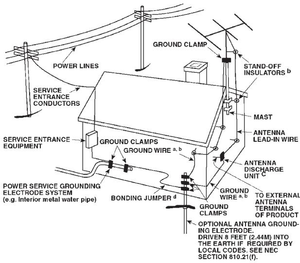
OUTDOOR ANTENNA GROUNDING
If an outside antenna is connected to your tuner or tuner-preamplifier, be sure the antenna system is grounded so as to provide some protection against voltage surges and built-up static charges. Article 810 of the National Electrical Code, ANSI/NFPA No. 70-1984, provides information with respect to proper grounding of the mast and supporting structure, grounding of the lead-in wire to an antenna discharge unit, size of grounding conductors, location of antenna discharge unit, connection to grounding electrodes and requirements for the grounding electrode.
a. Use No. 10 AWG (5.3mm2) copper, No. 8 AWG (8.4mm2) aluminium, No. 17 AWG (1.0mm2) copper-clad steel or bronze wire, or larger, as a ground wire.
b. Secure antenna lead-in and ground wires to house with stand-off insulators spaced from 4-6 feet (1.22 - 1.83 m) apart.
c. Mount antenna discharge unit as close as possible to where lead-in enters house.
d. Use jumper wire not smaller than No.6 AWG (13.3mm2) copper, or the equivalent, when a separate antenna-grounding electrode is used. see NEC Section 810-21 (j).
EXAMPLE OF ANTENNA GROUNDING AS PER NATIONAL ELECTRICAL CODE INSTRUCTIONS CONTAINED IN ARTICLE 810 - RADIO AND TELEVISION EQUIPMENT.
NOTE TO CATV SYSTEM INSTALLER: This reminder is provided to call the CATV system installer's attention to Article 820-40 of the National Electrical Code that provides guidelines for proper grounding and, in particular, specifies that the ground cable ground shall be connected to the grounding system of the building, as close to the point of cable entry as practical.


REAR PANEL CONNECTIONS
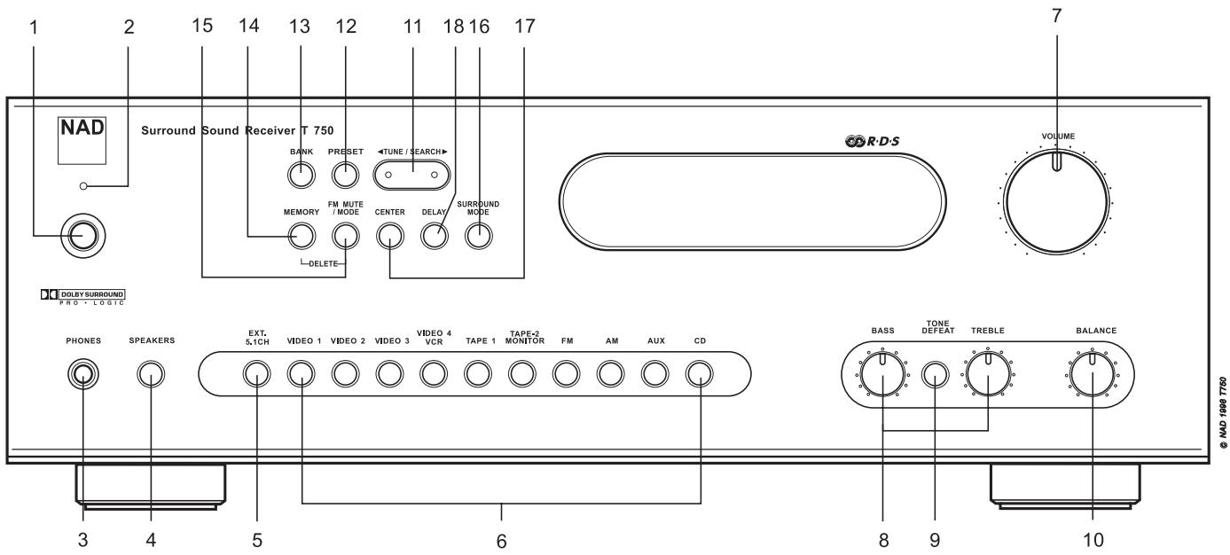
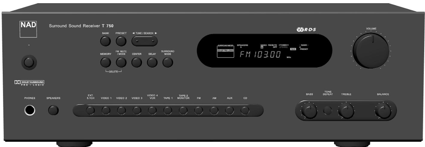
FRONT PANEL CONTROLS
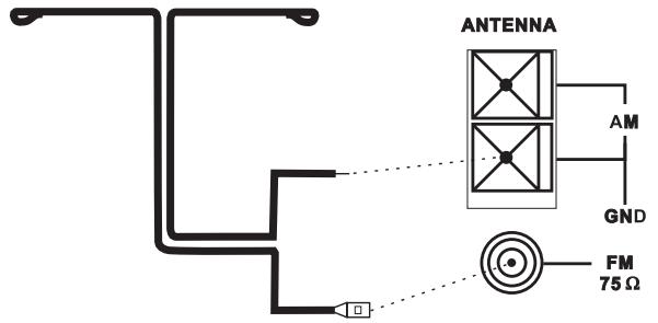
FIGURE 1
European and Australian models
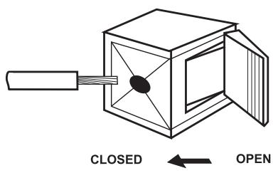
FIGURE 2
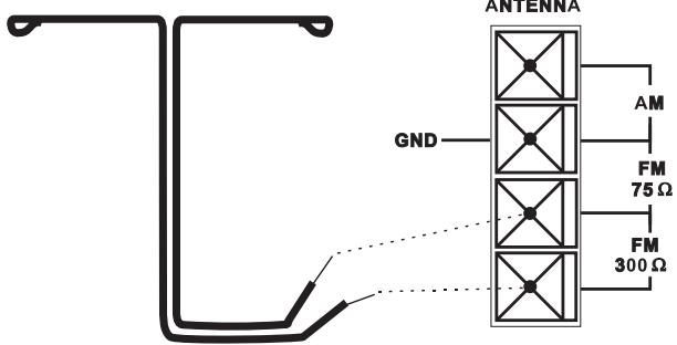
U.S.A. And Canadian models
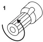
FIGURE 3
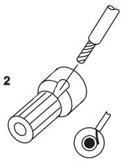
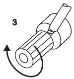
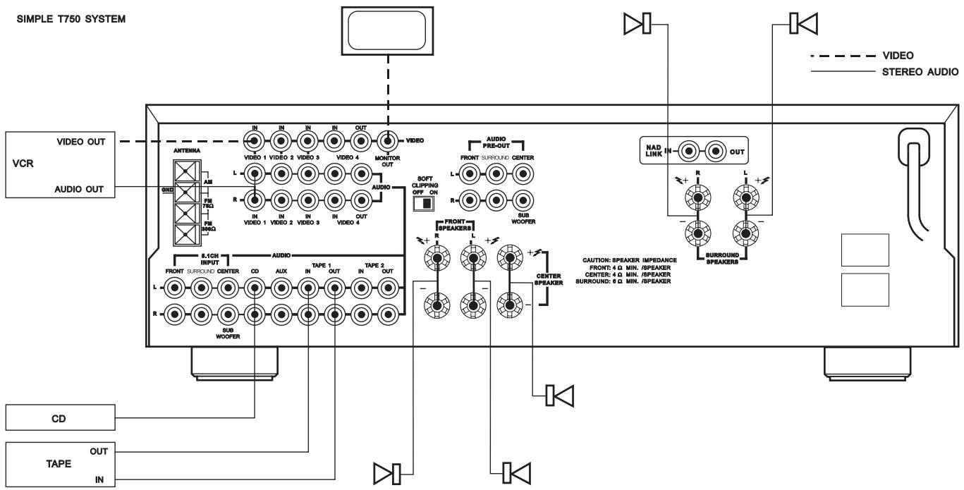
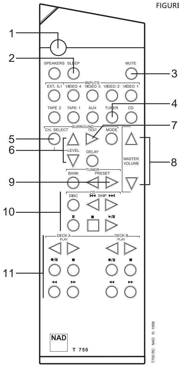
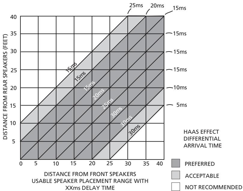
FIGURE 5
DOLBY DELAY
NAD T750 Surround Sound AM/FM Receiver
NOTES ON INSTALLATION
Your NAD T750 should be placed on a firm, level surface. Avoid placing the unit in direct sunlight or near sources of heat and damp.
Allow adequate ventilation. Do not place the unit on a soft surface like a carpet. Do not place it in an enclosed position such a bookcase or cabinet that may impede the air-flow through the ventilation slots.
Make sure the unit is switched off before making any connections.
The RCA sockets on your NAD T750 are colour coded for convenience. Red and white are Right and Left audio respectively, and yellow for NAD Link.
Use high quality leads and sockets for optimum performance and reliability. Audio RCA leads will function correctly for video signals, although it is recommended to use dedicated video leads where possible. Ensure that leads and connectors are not damaged in any way and all connectors are firmly pushed home.
For best performance, use quality speaker leads of 16 gauge (1.5mm) thickness or more.
If the unit is not going to be used for some time, disconnect the plug from the AC socket.
Should water get into your NAD T750, shut off the power to the unit and remove the plug from the AC socket. Have the unit inspected by a qualified service technician before attempting to use it again.
Do not remove the cover, there are no user-serviceable parts inside.
Use a dry soft cloth to clean the unit. If necessary, lightly dampen the cloth with soapy water. Do not use solutions containing benzol or other volatile agents.
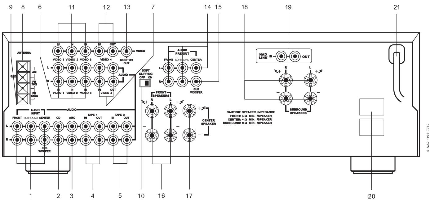
REAR PANEL CONNECTIONS
Inputs for the multi-channel audio signals from an external decoder, such as a DVD player with integrated Dolby Digital decoder. Use two twin RCA-to-RCA lead to connect the decoder's front left and right 'Audio Outputs' to the Front left and right inputs, and the decoder's Surround left and right outputs to the Surround left and right inputs. Use a third twin RCA-to-RCA lead to connect the decoder's subwoofer output to the Subwoofer input and the decoder's Centre channel output to the Centre channel input. Make sure you to follow colour coding of the plugs to ensure that both Centre and Subwoofer are connected correctly, for instance, use the red plugs at either end to connect the centre channel and the white plugs for the subwoofer channel.
Input for CD player (analogue audio signal) or other line-level signal source. Use a twin RCA-to-RCA lead to connect the CD player's left and right 'Audio Outputs' to this input.
Input for audio components. Use a twin RCA-to-RCA lead to connect the audio component left and right 'Audio Outputs' to this input.
4. TAPE 1
Connections for analogue recording and playback to an audio tape recorder of any type, such as a cassette, reel-reel, DAT, MD or DCC. Using twin RCA-to-RCA leads, connect to the left and right 'Audio Output' of the tape machine to the TAPE 1 IN connectors for playback. Connect the left and right 'Audio Input' of the tape machine to the TAPE 1 OUT connectors for recording.
5. TAPE 2
Connections for analogue recording and playback to a second audio tape recorder of any type. Using twin RCA-to-RCA leads, connect to the left and right 'Audio Output' of the tape machine to the TAPE 2 IN connectors for playback. Connect the left and right 'Audio Input' of the tape machine to the TAPE 2 OUT connectors for recording.
6. VIDEO 1 TO VIDEO 3 (AUDIO)
Inputs for the audio playback from a VCR or other video device such as a stereo TV, satellite or cable TV receiver or a Laser Disc. Using twin RCA-to-RCA leads, connect to the left and right 'Audio Out' of the VCR/TV/LD/satellite receiver to these inputs. These audio inputs are used in conjunction with the composite (line) video inputs marked VIDEO 1,VIDEO 2 orVIDEO 3.VIDEO 1 to 3 are used for playback only, useVIDEO 4 if you want to connect a VCR for recording and playback through the T750.
7. VIDEO 4 (AUDIO)
Connections for the audio recording and playback to a VCR or other video recorder. Using twin RCA-to-RCA leads, connect to the left and right 'Audio Out' of the VCR to the VIDEO 4 IN connectors for playback. Connect the left and right 'Audio In' of the VCR to the VIDEO 4 OUT connectors for recording. These audio inputs are used in conjunction with the composite (line) video inputs marked VIDEO 4 IN and the video outputs marked VIDEO 4 OUT.
8. AM ANTENNA
An AM loop antenna is supplied with the T750 and is required for AM reception. Open the clip terminal lever and insert the wire from the antenna. Closing the lever will lock the wire in place (Fig. 2). Test various positions for the antenna, but always ensure the loop is placed vertically for best reception. Placing the antenna close to large metal items such as metal shelves or radiators may interfere with reception.
NOTE: When reception is not satisfactory using the supplied AM loop antenna alone, connection of an external antenna is recommended. Do not remove the AM loop antenna. Do not connect anything other than a loop antenna to the AM ANTENNA terminal. The antenna cable to the loop antenna must not exceed 3 meters.
9. FM ANTENNA
A ribbon wire FM antenna is included and should be connected to the FM connector at the rear of the unit (Fig. 1). The ribbon aerial should be mounted on a vertical surface and placed so that it forms a 'T'.
Experiment with placement of the antenna to find the position that gives the best signal strength and lowest background noise. An inadequate FM signal normally results in high levels of hiss, especially in stereo, and interference from external electrical sources. In areas of poor FM reception, the tuner section's performance can be improved by using an externally mounted FM antenna. A qualified aerial installer will be able to advise and fit a recommended aerial for your reception conditions.
10. SOFT CLIPPING
When an amplifier is driven beyond its specified power output, a hard, distorted sound can be heard on very loud sounds. This is caused by the amplifier cutting off or 'hard clipping' the peaks of sound that it was not designed to reproduce. The NAD Soft Clipping circuit gently limits the output of the system to minimise audible distortion if the amplifier is over driven.
If your listening involves moderate power levels you may leave the Soft Clipping switch off. If you are likely to play at high levels that exceed the amplifier's power capability, then switch Soft Clipping on.
11. VIDEO 1 TO 3 (VIDEO)
Connection for the Composite video signal input for VIDEO 1,VIDEO 2 orVIDEO 3. Using a RCA-to-RCA lead, connect the 'Video Out' of the VCR, TV, Laser Disc or satellite/cable unit. VIDEO 1 to 3 can be used for video playback only. Use VIDEO 4 if you want to connect a VCR for recording and playback through the T750.
12. VIDEO 4 (VIDEO)
Connection for the Composite video signal input for VIDEO 4. Using a RCA-to-RCA lead, connect the 'Video Out' of the VCR to VIDEO 4 IN for playback. Connect VIDEO 4 OUT to the 'Video In' of the VCR to copy video signals from VIDEO 1,VIDEO 2 orVIDEO 3.
13. MONITOR OUT
Composite video output for connecting a TV or Video Monitor to view video sources connected to VIDEO 1 toVIDEO 4. Using a RCA-to-RCA lead, connect the 'Video Line In' on the TV or monitor to the MONITOR OUT. This output can also be used as an additional recording output if required. Video monitoring must then be done via the output of the video recorder.
14. AUDIO PRE-OUTS
The NAD T750 receiver has five power amplifiers built-in to power all the speakers connected to it (Left, Right, Centre, Left Surround, Right Surround). It is also possible to use the T750 as a pre-amplifier to drive external power amplifiers. This way, you use all the control functions the T750 provides, such as input select, surround mode, volume, tone controls, etc., but the external power amplifier actually powers the speaker connected it instead of the T750's integrated power amplifier for that channel.
Connect the RCA-to-RCA leads from the Front left and Right, Centre, and/or Surround Left and Right Audio pre-out connectors to the external amplifiers. Connect speakers to the external amplifiers.
NOTES: Never connect the T750's speaker outputs and the speaker outputs of an external amplifier to the same speakers.
Make sure the T750 and the power amplifiers it will be connected to are switched off. With volume turned down to a low level, switch power on only after all connections have been made.
15. SUB WOOFER OUT
Unlike for the full range five channels as described above, there is no power amplifier built-in for an additional subwoofer. The Subwoofer pre-out allows for connection to a sub-bass speaker system with its own power amplifier.
16. FRONT SPEAKERS
These speaker outputs are switched on and off by using the SPEAKERS button on the front panel.
Connect the right speaker to the terminals market R + and R - ensuring that the R + ^ is connected to the ^+ terminal on your loudspeaker and the R - ^ is connected to the loudspeaker's -terminal. Connect the terminals marked L + ^ and L - ^ to the left speaker in the same way.
Always use heavy duty (16 gauge; 1.5mm or thicker) stranded wire to connect loudspeakers to your T750.
Unscrew the speaker terminal's plastic bushing. Insert the pin or bare cable end into the hole of the terminal and then secure the cable by tightening down the terminal's bushing (Fig. 3).
To avoid any danger of bare metal from the speaker cables touching the back panel or another connector, ensure that there is only 1/2 (1.27cm) of bare cable or pin and no loose strands of speaker wire.
CAUTION: This unit is designed to produce optimum sound quality when speakers with impedances within the set's ranges are connected. Please check the following information and choose speakers with the correct impedances for the connections.
FRONT SPEAKERS: 4 ohms min. per speaker
CENTRE SPEAKER: 4 ohms min.
SURROUND SPEAKERS: 6 ohms min. per speaker
17. CENTER SPEAKER
This connects the centre loudspeaker that is used when the T750 is operated in Dolby* Pro Logic, Dolby 3 stereo mode or with the 5.1 Ch. input selected. Connect the 'Center +' to the '+' terminal on your centre loudspeaker and the 'Center -' to the loudspeaker's '-' terminal.
Strip 1/2 (1.27cm) of insulation from the end of the speaker cable and twist the bare wires so that there are no loose strands. These terminals operate in the same way as the Front Speaker terminals. These speakers operate in conjunction with the Front Speakers and are switched on and off by using the SPEAKERS button on the front panel.
This connects the rear loudspeakers that are used when the T750 is operated in Dolby Pro Logic, Hall modes or with the 5.1 Ch. input. Connect the right Surround speaker to the terminals market R + and R - ensuring that the R + is connected to the + terminal on your loudspeaker and the R - is connected to the loudspeaker's - terminal. Connect the terminals marked L + and L - to the left speaker in the same way.
Strip 1/2 (1.27cm) of insulation from the end of the speaker cable and twist the bare wires so that there are no loose strands. These terminals operate in the same way as the Front Speaker terminals. These speakers operate in conjunction with the Front Speakers and are switched on and off by using the SPEAKERS button on the front panel.
19. NAD-LINK IN OUT
The NAD-Link connector is used to pass commands from other units fitted with NAD-Link connectors. This allows centralised control of a complete system, and also allows some of the basic functions of other NAD components (such as a CD player or cassette deck) also equipped with NAD-Link to be controlled with the receiver's remote control. To function with such other units, connect the T750's NAD-Link Out to the NAD-Link In on the other unit. NAD-Link connectors can be daisy-chained, IN to OUT, so that a whole system can be controlled from the remote control facilities of one unit.
20. AC OUTLETS
(120V NORTH AMERICAN VERSIONS ONLY) The AC power cords of other units in the audio system can connected directly to the T750's AC outlets. If another stereo component is plugged into the SWITCHED AC outlet, power will be supplied to that component only when your T750 is turned on. If another stereo component is plugged into the UNSWITCHED AC outlet, power will be supplied whether your T750 is on or off.
NOTE: The AC outlets should be used with units with a COMBINED power consumption of no more than 120 Watts.
21. AC POWER CORD
After you have completed all connections to the amplifier, plug the AC line cord into a "live" wall socket.
FRONT PANEL CONTROLS
POWER, SPEAKERS AND HEADPHONE FUNCTIONS
1. POWER
Press the POWER button to switch the receiver to its 'Stand-by' mode. The Stand-by indicator (No. 2) over the power button will light up. On the front panel, press any of the input selector buttons (No. 6) to switch to receiver on. From the remote control, press the green Stand-by button (located just over the Speakers button) to switch the unit on. The display will light up indicating which input was selected; the Stand-by indicator will extinguish.
Pressing the POWER switch again will turn the unit OFF completely. The NAD T750 receiver uses a memory back-up system to store surround sound trim settings and Preset station information for the tuner section. This information is retained for several weeks, even the unit is switched off completely or unplugged.
REMOTE CONTROL
STAND-BY button (green, No. 1 on remote control drawing): Press this button to switch the unit from operating to the Stand-by mode and vice versa: Press this button again to switch to unit on from Stand-by; the last selected source will be indicated in the display.
NOTE: Stand-by mode is indicated by the Stand-by indicator (No. 2) just over the green POWER button on the front panel (No. 1) In Stand-by mode the T750 uses very little power. However, it is recommended that you switch the unit totally off if it is not going to be used for more than a couple of days. Switch off completely by pressing the POWER button on the front panel (No. 1), all lights will extinguish. Press this button to switch the unit on. To switch the unit off, press this button again.
2. STANDBY
This green LED will light up when the receiver is switched On, but in Stand-by mode. Refer to section 1 in this chapter for more information. The LED will also light up when the receiver receives a remote control command from the supplied handset.
3. HEADPHONE SOCKET
A 1/4 stereo jack socket is supplied for headphone listening. The socket has its own amplifier which will drive conventional headphones of any impedance. The volume, tone and balance controls are operative for headphone listening. Use a suitable adapter to connect headphones with other types of connectors such as 3.5mm stereo 'personal stereo' jack plugs. Press the Speakers button (No. 4) to turn off all speakers for headphone listening only.
NOTE: Listening at high levels can damage your hearing.
4. SPEAKERS
The SPEAKERS button turns the speakers connected to the FRONT, CENTRE and SURROUND SPEAKERS terminals on or off. When the speakers are turned on, the SPEAKERS indicator lights up.
Press Speakers to switch off all speakers for headphone listening (No. 3) without the speakers playing simultaneously.
NOTE: Always turn the volume down when engaging or disengaging Speakers.
Selects the multi-channel output signal from the DVD player or external decoder source connected to the 5.1 Ch. input as the active input.
NOTES: The Surround mode button (No. 16) does not have any effect in this mode.
No audio signal is available from the Tape 1, Tape 2 and Video 4 outputs when the Ext. 5.1Ch, input has been selected.
6. VIDEO 1 TO VIDEO 4, TAPE 1, TAPE 2 MONITOR, FM, AM, AUX, CD
These buttons select the active input to the T750 and the signal sent to the loudspeakers and the Tape, Video 4 and TV monitor outputs. The name of the Input and Surround Mode will be shown in the Display Panel.
VIDEO 1 toVIDEO 3 Selects the signal from stereo TV/Satellite/Cable receiver or Laser Disc connected toVIDEO 1,2 or 3 as the active input. Video 1,2 or 3 is shown in the Display Panel when these are selected.
VIDEO 4 VCR Selects the VCR connected to VIDEO 4 as the active input. Video 4 is shown in the Display Panel when selected.
TAPE 1 Selects Tape 1 as the active input.
TAPE 2 MONITOR Selects the output from a tape recorder when playing back tapes or monitoring recordings being made through the Tape 2 sockets. Press the Tape 2 button once to select it and again to return to the normal input selection.
Tape 2 is a Tape Monitor function which does not override the current input selection. For example, if the CD is the active input when TAPE 2 is selected, then the CD signal will continue to be selected and sent to both the TAPE 1, TAPE 2 and Video 4 OUTPUT sockets, but it is the sound from recorder connected to Tape 2 that will be heard on the loudspeakers. When Tape 2 Monitor is selected, "TAPE 2" is indicated in the alphanumeric section of the display for 3 seconds before it defaults to indicating the active input again. The box just over the alphanumeric section indicating "T-2 MONITOR" will remain lit until Tape 2 is disengaged again.
FM Selects FM radio. FM is also automatically selected when an FM Preset is selected.
AM Selects AM radio. AM is also automatically selected when an AM Preset is selected.
AUX Selects the auxiliary audio component as the active input.
CD Selects the CD as the active input.
VOLUME, BALANCE AND TONE FUNCTIONS 7. VOLUME
The VOLUME control adjusts the overall loudness of the signals being fed to the loudspeakers. It is motor driven and can be adjusted from the remote control handset using the Master Volume or button. The Volume control does not affect recordings made using the Tape and Video 4 outputs but will affect the signal going to the Pre-amp output (Audio Pre Out).
On the remote control handset, press the Mute Button to temporarily switch off the sound to the speakers and headphones. Mute mode is indicated by "AUDIO MUTE" flashing in red in the display area. Press Mute again to restore sound. Mute does not affect recordings made using the Tape and Video 4 outputs but will affect the signal going to the Pre-amp output (Audio Pre Out).
8. BASS & TREBLE CONTROLS
The T750 is fitted with BASS and TREBLE tone controls to adjust the overall tonality of your system.
The 12 o'clock position is 'flat' with no boost or cut and a detent indicates this position. Rotate the control clockwise to increase the amount of Bass or Treble. Rotate the control anti-clockwise to decrease the amount of Bass or Treble. These controls affect the Left and Right Front speakers only. In Dolby Pro Logic, Dolby 3 Stereo, Hall modes or the EXT. 5.1CH input selected, the Centre and Surround speakers maintain a 'flat' response, regardless of the tone control settings. The Tone controls do not affect recordings made using the Tape or Video line outputs but will affect the signal going to the Pre-amp outputs (Audio Pre Out).
9. TONE DEFEAT
The Tone Defeat switch by-passes the tone control section of the T750. If the Tone Controls (No. 8) are not normally used and left in the 12 o'clock position, then it is advisable to switch out the Tone Control section altogether by using this switch. In the 'out' position, the Tone Control circuits are active, pushing the Tone Defeat switch in bypasses the Tone Control section.
10. BALANCE
The BALANCE control adjusts the relative levels of the Left and Right Front speakers. The 12 o'clock position provides equal level to the Left and Right channels. A detent indicates this position.
Rotating the control clockwise moves the balance towards the right. Rotating the control anti-clockwise moves the balance to the left. The BALANCE control does not affect recordings made using the Tape or Video line outputs but will affect the signal going to the Pre-amp outputs (Audio Pre Out).
TUNER
11. TUNE/SEARCH AND
The function of these buttons depends on the tuning mode selected with the Preset button (No. 12). The Preset button toggles between the two operation modes:
a) Preset mode (indicated in the display area): Press the button to scroll to a lower number Preset; press the button to scroll to a higher Preset number. This is a "wrap-around" function, so that going from the highest number Preset the tuner will go to the lowest Preset number when is pressed.
a) Tune mode: Press the or for more than 1/2 second to engage automatic tuning respectively up or down the frequency band. The tuner will search automatically for the first reasonably strong radio station, where it will stop. Press the Tune/Search button again for 1/2 second to start searching again.
NOTE: Automatic tuning is only available on FM.
By briefly tapping the or you can engage manual tuning respectively up or down the frequency band for precise tuning to a specific frequency. With each successive tap of the keys, the tuner will take 0.05 or 0.1MHz steps (depending on version) on FM so you can accurately tune into the desired frequency. For AM the tuning steps can be 9kHz or 10kHz , depending on the version of your T750. This tuning mode can also be useful when trying to receive a radio station which is too weak for the auto search mode. When tuned accurately to a station, "TUNED" will light up in the display.
With stations carrying RDS information, the station's RDS name is displayed, Program Service (PS; normally the station's calling letters, BBC R3, for instance).
Refer also to chapter "Storing AM and FM stations" for additional information.
NOTE: The 120V versions (North America) do not have RDS (Radio Data System).
12. PRESET
The Preset button toggles between the Preset and Tune mode. When Preset mode is selected, "PRESET" lights up in the display area.
Up to 30 Presets, either AM or FM, can be stored in three Preset Banks, which can contain up to 10 Preset stations each. The Preset number is shown in the Display Panel.
Refer also to section 11 and chapter "Storing AM and FM stations" for additional information.
13. BANK
Pressing Bank switches between the T750's three Preset Memory Banks (A, B or C). Each of these banks can hold up to 10 Preset stations. These Banks can contain a mix of AM or FM stations each. The Bank selected is shown in the Display Panel. You can use the banks to sort your Presets, for instance by station type (Bank A for rock/pop; Bank B for Classical music; Bank C for Jazz).
Refer also to chapter "Storing AM and FM stations" for more information.
The remote control handset also has a Bank button and performs the same function.
14. MEMORY
The Memory button is used to store stations into the three Preset Memory Banks. Used in conjunction with the Tune/Search (No.11) buttons. When Memory is active, the Preset number flashes and the red 'MEMORY' indicator is shown in the Display Panel.
Refer also to chapter "Storing AM and FM stations" for more information.
15. FM MUTE/MODE
This button combines two functions; it switches the tuner from Stereo to Mono and disengages the muting circuitry at the same time. The muting circuit will mute the tuner in between radio stations when searching or tuning. This way the tuning noise is avoided.
Very weak radio station signals however may be suppressed by the mating circuit. if such a very weak station is in stereo it will have a high level of background hiss. Switching to Mono Mode and disengaging the mating circuit by depressing the FM MUTE/MODE button will allow the station to be heard and will cancel most or all of this background noise.
In normal operation the mute circuit is engaged, the display indicates "FM MUTE ON". Press the FM Mute/Mode button to disengage the muted circuit and switch from stereo to mono reception. The status of FM Mute/Mode is indicated in the display. Also, "STEREO" will extinguish if a stereo broadcast was received. Press the FM Mute/Mode switch again to return to Auto Stereo FM operation.
SURROUND FUNCTIONS
16. SURROUND MODE
The Surround Mode button scrolls through the T750's surround modes: Dolby Pro Logic, Dolby 3 Stereo, Hall and By-Pass (normal Stereo).
Dolby Pro Logic and Dolby 3 Stereo both decode the surround sound signals encoded in movie sound tracks from video or TV. To decode correctly, the video or TV signal must be of a Dolby Surround or Dolby Stereo soundtrack and coming from a stereo VCR, TV or satellite/cable receiver.
In the Dolby Pro Logic the rear Surround speakers are also activated. Use of a centre channel speaker is optional (set with the Centre button No. 17).
In the Dolby 3 Stereo mode, the rear Surround speakers are inoperative; the centre channel however is activated in this mode. Dolby 3 Stereo can be a good alternative to Pro Logic if it isn't practical or if space doesn't allow for the installation of Surround speakers.
For more information refer also to the chapter "Setting up the Surround System" and appendix "A short guide to Surround Sound".
In the HALL mode, a realistic level of ambience of surround sound is added to a normal stereo source such as a CD or FM radio. The centre channel is inoperative in this mode.
BY-PASS switches to normal Stereo operation.
The selected mode is displayed in the main area of the Display Panel for 3 seconds and is continuously shown in Surround Mode area of the Display Panel.
As an additional convenience feature, your T750 memorises which surround mode you have used with the given input selection. When you next select that input, your T750 will automatically choose the same Surround mode again. If you normally use Dolby Pro Logic mode on the Video 1 and Video 2 inputs, Dolby 3 Stereo mode on the Video 3 input, Hall mode on FM, and By-Pass (Stereo) on the others, pressing the Input Selector will automatically default to the right Surround mode without having to separately press the Surround Mode button.
NOTES: An external source such as a decoder or DVD player with a decoder built-in (Dolby Digital, DTS* for instance) can be connected to the 5.1Ch input (No. 5). When the EXT 5.1 CH. input is selected, no other surround modes are available, so "SURROUND MODE" extinguishes in the display panel.
17. CENTER
Selects the type of centre speaker used on the main speaker system. The Center button is only operative with Dolby Pro Logic or Dolby 3 Stereo selected.
In Dolby Pro Logic mode NORMAL, WIDEBAND, PHANTOM are the available options. In Dolby 3 Stereo mode NORMAL and WIDEBAND are available. Select the mode appropriate to the T750's set-up
The NORMAL mode is used when the centre speaker is smaller than the front left and right speakers. This mode produces a true centre image with the very low frequencies (below 70Hz ) filtered out.
The WIDEBAND mode is used when the centre speaker is the same type as the front left and right speakers. This mode produces a true centre image with a full frequency range and no low frequency filtering.
The PHANTOM mode is used when there is no centre speaker installed. The T750 places the centre information equally on the left and right front speakers so producing a 'Phantom' central sound image.
The selected Center Mode is displayed for 3 seconds in the main area of the Display Panel. It is stored in the T750's memory and will be automatically recalled each time the unit is switched on.
18. DELAY
Selects the amount of delay applied to the surround speakers when the T750 is used in DOLBY PRO LOGIC or HALL modes.
Pressing the DELAY button steps the Delay times in 5mS steps from 5mS to 30mS for Hall mode and from 15mS to 30mS for Dolby Pro Logic mode. Separate delay times can be stored for DOLBY PRO LOGIC and HALL modes and are held in the T750's memory. They are automatically recalled each time the DOLBY PRO LOGIC or HALL mode is selected.
This function can be altered only when the T750 is in DOLBY PRO LOGIC or HALL Mode.
Refer also to the chapter "Setting up the Surround Sound system" for more information.
STORING AM & FM STATIONS TO STORE A PRESET
- Tune to the radio station you wish to enter into a Preset (refer to chapter "Front Panel Controls" section 11). If the station is transmitting RDS information, the RDS indicator will light up and station initials will be shown in the Display Panel. If a non-RDS station is found, then just the frequency will be shown.
- To store that station as a Preset, press Memory (No. 14). The Memory indicator will be displayed and the Preset section will flash in the Display Panel.
- Press Bank (No. 13) to select which of the three Banks of Presets (A, B or C) you want to store the station into. Press either the Tune/Search or button to select which Preset number you wish to assign to the station (from 1 to 10), shown as a flashing number in the Display Panel, and then press Memory (No. 14) again. The Memory light in the Display Panel will go out and the station is now stored in your NAD T750's memory.
To exit the Memory mode without storing a station, leave all the tuner controls untouched; the Memory mode will automatically cancel itself after 8 seconds. The Memory Presets have a memory back-up, so they will remain stored for several weeks even if the Receiver is switched off or unplugged from the mains supply.
NOTE: You can enter a new station into an unused Preset or overwrite an existing programmed Memory Preset. By doing this you will replace the radio station previously held on that Preset number.
RECALLING A PRESET STATION
- To select a Preset station, select the Preset mode by pressing the Preset button (No. 12) until "PRESET" lights up in the display.
- By pressing the Bank button (No. 13) select which Bank of Presets you want to use (A, B or C, indicated in the display).
- Press either the Tune/Search or buttons (No. 11) until the right Preset is found and shown in the Display Panel.
NOTE: Any unused Presets will be skipped and it is not possible to select a Bank unless it has at least one Preset stored into it.
NOTE: The 120V versions (North America) do not have RDS (Radio Data System).
DELETEING A STORED PRESET:
You can empty a Preset by deleting the stored information:
- Select the Preset to be emptied.
- Press the Memory button (No. 14), hold it down and press the FM Mute/Mode button (No. 15). The Preset will then be deleted and '—' appears as the Preset number.
You can also store a new station into a used Preset, by simply going through the Preset storing process and placing a new station over the existing one.
REMOTE CONTROL
The T750's Remote Control handles all the key functions of the T750 and has additional controls to remotely operate NAD Cassette and CD machines. It will operate up to a distance of 16ft (5m).
Alkaline batteries are recommended for maximum operating life. Two AAA (R 03) batteries should be fitted in the battery compartment at the rear of the Remote Control handset. When replacing batteries, check that they have been put in the right way round, as indicated on the base of the battery compartment.
The EXT 5.1, Video 1 to 4, Tape 1, 2, Aux and CD Input selector, Speaker, Bank and Surround Mode buttons perform the same function as those on the front panel of the T750. There are a few differences and extra functions with the remote control handset however (numbers refer to fig. 4):
1. STAND-BY
Press this green button to switch the unit from operating to the Stand-by mode and vice versa: Press this button again to switch the unit on from Stand-by; the last selected source will be indicated in the display.
2. SLEEP
Press SLEEP to make the T750 automatically switch off after a preset number of minutes. Pressing the SLEEP button once will set the sleep time to 90 minutes, after which the T750 will automatically switch off into Standby mode. Sleep mode and the Sleep delay is shown on the Display Panel. To adjust the Sleep Delay, hold down the SLEEP button. This will reduce the sleep time in 10 minute increments, as shown in the Display Panel. To cancel the Sleep mode, continue pressing the SLEEP button until the source name appears in the Display Panel. Pressing the POWER or STANDBY button will also cancel the Sleep mode.
3. MUTE
Press the MUTE button to temporarily switch off the sound to the speakers and headphones. Mute mode is indicated by "AUDIO MUTE" flashing in red in the display area. Press MUTE again to restore sound. Mute does not affect recordings made using the Tape outputs but will affect the signal going to the Audio Pre-outs.
4. TUNER
Whereas the T750's front panel has separate buttons for AM and FM, the remote control has a single Tuner button. The tuner section can be activated by pressing Tuner. The tuner button will select the tuner as the active input and revert to the last station tuned to on either the AM or FM band.
5. CHANNEL SELECT
Press the Ch. Select button to address the Centre, Left Surround or Right Surround channels for adjustment of volume trims relative to Left and Right channels. Each successive press of the button causes the T750 to scroll to the next channel: Centre Right Surround Left Surround Centre, etc. The display indicates which channel is selected. Within the default time of 8 seconds, use either the Level ▲ or ▼ (No. 7) to change relative volume level for the desired channel.
Refer also to the chapter "Setting up the Surround Sound system" for more information.
6. LEVEL
With the Level ▲ or ▼ (No. 7) buttons the relative volume level trims for Centre, Left and Right Surround channels can be adjusted. Press the Channel Select button (No. 5) to select the channel for which you wish to adjust the level.
Refer also to the chapter "Setting up the Surround Sound system" for more information.
7. TEST
Pressing the Test button engages the Test generator which generates a noise signal that scrolls to each of the speaker channels (Left Centre Right Left & Right Surround Left etc. for Dolby Pro Logic; Left Centre Right Left etc. for Dolby 3 Stereo), so that each can be adjusted for equal loudness at your listening position. The Display Panel shows which speaker is being fed with the test signal.
8. MASTER VOLUME
Master Volume or respectively increases or decreases the Volume setting for all speakers. The motorised Volume Control on the front panel will indicate the level set. The VOLUME control does not affect recordings made using the Tape and Video 4 outputs but will affect the signal going to the Pre-amp output (Audio Pre Out).
9. PRESET
OR
The Preset or buttons will allow direct selection of the desired Preset without having to select Preset Tuning mode first.
Other than the commands relating to the NAD T750 receiver itself, there are other buttons which will operate most NAD CD players and Cassette decks equipped with NAD Link.
10. CD PLAYER CONTROL
(for use with NAD CD Player)
II engages Pause
■ engages Stop
/ engages Play or toggles between Play and Pause
or engages Track skip; Press once to respectively go to the next track or to return to start of current or previous track. DISC Go to next disc (for NAD CD changers).
11. CASSETTE DECK CONTROL
(For use with single (DECK B) or double transport (A and B) NAD Cassette Decks)
or engages Forward Play or Reverse Play.
/ Record / Pause. Press to put cassette deck into recordpause. Press Play to start recording.
Stops Play or Recording.
engages Rewind.
engages Fast Forward.
NOTES: Direct sunlight or very bright ambient lighting may affect the operating range and angle for the remote control handset.
The infrared remote control command receiver, located on the far left of the display window, receives commands from the remote control. There must be a clear line-of-sight path from the remote control to this window; if that path is obstructed, the remote control may not work.
To work at its best, the output levels of the T750's surround facilities need to be adjusted so that there is an even balance of sound from all the speakers in the system.
The Delay time for the Surround speakers also needs to be correctly set for your normal listening position. Refer to the section "Setting the Surround Delay" in this chapter for more information.
The adjustment of speaker levels is done using the Test (No. 7), Channel Select (No. 5) and Level (No. 6) functions on the Remote Control. It is important first to correctly phase all the speakers in the system. Check that the positive (+) terminals of the T750 speaker outputs are connected to the positive (+) connector on the each of the speakers. Refer also to the section "Speaker Phase" in the chapter "Appendix" for additional information.
Before starting the set-up procedure, ensure that the Centre (No. 17) mode is set correctly for your speaker configuration. Set the BALANCE control to the position normally used for stereo sources (usually the 12 o'clock position).
- With the speakers connected and the VOLUME turned down to zero, select the Dolby Pro Logic or Dolby 3 Stereo mode using the Surround Mode button (No. 16) and press Test on the Remote Control (No. 7 in fig. 4). This generates a test signal that scrolls to each of the speaker channels (Left Centre Right Left & Right Surround Left etc. for Dolby Pro Logic; Left Centre Right Left etc. for Dolby 3 Stereo), so that each can be adjusted for equal loudness at your listening position. The Display Panel shows which speaker is being fed with the test signal. Turn the Volume (No. 7; No. 8 in fig. 4) up until the signal is moderately loud through the Left and Right Front speakers.
- Press the CH.Select button (No. 5 in fig. 4) on the remote control until "CENTRE" appears in the display. Within the 5s default time, press the Level or button on the Remote Control (No. 6 in fig. 4) to increase or decrease the Centre speaker's loudness so that it matches the levels being produced by the Left and Right speakers. The relative level of the Centre channel is shown in the Display Panel and can be changed in dB steps.
- In Dolby Pro Logic or Hall mode Press the CH.Select button (No. 5 in fig. 4) on the remote control until "R-SUR." appears in the display to adjust the Right Surround speaker. Again, within the 5s default time, use the Level or buttons to set the level so that it matches the levels produced by the Left and Right Front speakers.
- Press the CH.Select button (No. 5 in fig. 4) on the remote control until "L-SUR." appears in the display to adjust the Left Surround speaker. Repeat the same procedure as described above to match the levels produced by the Left and Right Front speakers
A more accurate adjustment can be made using a sound level meter, if available. Set the meter to 'Slow' and 'C-weighted' modes and re-check the settings with the meter placed in several different positions in the general listening area.
If a Sub-Woofer is used on the system, adjust the Sub-Woofer's level control so that it is audible, but does not dominate the sound. Sub-Woofer levels can be later fine-tuned using programme material. The Level settings are stored in the T750's memory. They are automatically recalled when the unit is switched on.
NOTES: In Dolby 3 Stereo Surround mode the Surround channels are inoperative. Only the Centre channel can be accessed to adjust in level.
In Dolby Pro Logic with Phantom Centre mode selected, and Hall Surround Modes the Centre channel is inoperative. Only the Left Surround and Right Surround channels can be accessed to adjust in level.
Because the Surround speakers are usually closer to the listener than the Front speakers, there is a tendency for the ear to localise sounds to the rear, because the ear takes most notice of the sounds that arrive at the head first.
To resolve this problem, the Dolby Pro Logic circuit includes a Surround delay. This ensures sound coming from the surround speakers always arrives at the listener's ears after the sound from the front speakers.
The exact amount of delay required depends on the relative distances between the Front and Surround speakers and the listening position in the room.
First make a note of the distance between the surround speakers and the listening position. Now make a note of the distance between the front speakers and the listening area. Note where the two distances intersect this will give the correct Delay setting (see fig. 5).
To adjust the Delay setting, put the T750 into Dolby Pro Logic mode and press DELAY on the front panel (No. 18) or the Remote Control. Continue pressing DELAY until the correct value is shown in the Display Panel.
The Delay settings are stored in the T750's memory. They are automatically recalled when the unit is switched on.
APPENDIX
A SHORT GUIDE TO SURROUND SOUND
Since the middle of the 1970's, film companies have been making movies in increasing numbers in Dolby Stereo, the four channel surround sound system available in most movie theatres today.
Fortunately it is a simple operation to take the film's Dolby Stereo soundtrack and place it on a stereo VHS videotape, Laser Disc or Video-CD. The sound track does require some conversion for home use, and the domestic version of Dolby Stereo is called Dolby Surround.
Today, most video copies of movies also contain this surround information originally designed for the movie theatre. As well as videos, Dolby Surround is also being used on TV programmes and on music CDs, and all of these can be decoded using your T750. Unlike the quadraphonic systems which tried to produce pinpoint sounds coming from all directions, Dolby Surround is designed to give you a clear front image with the Surrounds filling the room with atmospheric sound.
For best results, the Surround loudspeakers should not beam the sound directly at the listener. One way of achieving this is to use 'dipole' Surround speakers which aim the sound down the walls rather than directly into the room. An alternative is to use standard small loudspeakers for Surrounds, but not to point them directly at the listening position. It is always worth experimenting with various Surround speaker positions to see which works best in your room.
With the recent advent in digital technology, various new surround systems have emerged. Best known are Dolby Digital and DTS, both are sometimes referred to as 5.1 formats (5 independent, full range channels and 1 "Effects channel" for bass). The Dolby Digital and/or DTS formats can be found on some Laser Discs and DVDs, for instance.
Using the NAD T750's Ext. 5.1Ch. input, the decoded, analogue audio Dolby Digital or DTS can be directly connected. Already there are DVD players available with integrated Dolby Digital decoder, which will connect directly to the T750.
SPEAKER PLACEMENT
Placement of the speakers in a Dolby Pro Logic surround system plays an important role in the performance of the system.
FRONT SPEAKERS
The front speakers should be placed with the left and right speakers evenly spaced either side of the TV screen. The centre speaker should be placed underneath or above the TV monitor so that dialogue is localised close to the TV image.
SURROUND SPEAKERS
The surround speakers are used to create a diffuse room-filling atmospheres rather than pinpoint sound effects. Surround speakers should be wall or shelf mounted fairly high up either on the side walls, rear wall or in the rear corners. Speakers can be mounted facing sideways or upwards to increase the diffusing effect by bouncing the sound off the walls and ceiling before it reaches the listener.
SUB-WOOFER
The very low frequency sounds produced by the sub-woofer are difficult to localise so the Sub-woofer can be placed virtually anywhere in the room. Placing Sub-wooers against walls or in corners will increase the amount of bass produced in the room.
WHY HAVE A CENTRE SPEAKER?
The Dolby Pro Logic decoder produces three separate outputs for the Front signals - left, centre and right. On most soundtracks, the sound effects and music are spread across all three front channels but the dialogue is mainly fed to the centre channel only.
Using a separate centre channel speaker will allow the dialogue to cut through even the biggest sound effects and musical scores. Having the sound spread across three front speakers also stabilises the stereo image, making the usable listening area much bigger.
If you are using the T750 with only two front speakers, setting the Centre mode (No. 17) to PHANTOM will place the centre information on both the left and right speakers. This creates the impression of a centre channel sound source.
For best results, you should consider using a centre speaker. Ideally it should be the same type as the left and right speakers, although there are now many new speakers, such as the NAD 808CC, which are specifically designed as centre channel add-ons for existing stereo systems.
NOTE: Ensure that any speaker that is to be used near a TV or monitor is of the magnetically shielded type (see loudspeaker's instruction manual). It is not normally possible to modify an unshielded speaker to work very close to a TV or monitor.
WHY HAVE A SUB-WOOFER?
Many film soundtracks rely heavily on very low frequency sound effects which are difficult for normal hi-fi speakers to reproduce. To faithfully reproduce these low frequencies you can use a specially designed low frequency loudspeaker with its own built-in amplifier. Because it is difficult to hear which direction very low frequencies are coming from, you only normally need one subwoofer and this can be placed virtually anywhere in the room. The Sub-Woofer output of the T750 is designed specifically to drive a sub-woofer system.
SPEAKER PHASE
In a home theatre system it is important that the three front speakers are all in phase compared to each other. Incorrect phase will produce a poor stereo image and an apparent lack of bass. If you are using speakers all from one manufacturer and power amplifiers all from one manufacturer then to ensure correct phasing of the system, just make sure that all the red (+) connectors on the power amplifier speaker outputs are connected to the red (+) connector on the loudspeaker.
If you are using a mix of amplifiers or speakers from different manufacturers, or using amplifiers in 'bridge' mode, then it is possible that the phase can be internally reversed in the some of the amplifiers or speakers, so you must check for correct phase by listening.
To check phase by listening, set the T750 to Dolby Pro Logic and FM Mute/Mode OFF and select a FM radio station. This will give you the same sound on all three front speakers. Disconnect the surround speakers and the right front speaker. A stable sound image should be heard as though it comes from a single point between the centre and left front speakers. If the signal sounds diffuse and not as though it is coming from a single point in space, reverse the connections to the centre loudspeaker. The signal should now appear to come from a single point between the left and centre speakers.
Reconnect the right front speaker and disconnect the left front speaker and repeat the procedure for the right and centre front speakers, changing the connection only on the right front speaker if the phase needs correction.
Surrounds will normally be in phase with each other if they have been correctly connected.
There is no absolute rule regarding the relative phase between the front speakers and the surround speaker pair or the Sub-Woofer (if used). Connecting these using the red (+) connector from the amplifier to the red (+) connector on the speakers should produce correct results. But in some rooms reversing the connections may produce a noticeable increase in bass response or an improvement in overall stereo imagery, so you may wish to experiment with reversing the connections on both the surrounds or reversing the connections to the sub-woofer.
| TROUBLESHOOTING |
| Problem | Cause | Solution |
| NO SOUND | •Power AC lead unplugged or power not switched on
•Tape 2 Monitor selected
•Mute on
•Speakers not switched on | •Check if AC lead is plugged in and power switched on
•De-select Tape 2 Monitor mode
•Switch off Mute
•Switch Speakers on |
| NO SOUND ONE CHANNEL | •Balance control not centred
•Speaker not properly connected or damaged
•Input lead disconnected or damaged | •Centre Balance control
•Check connections and speakers
•Check leads and connections |
| NO SOUND ON SURROUND CHANNELS | •No surround mode selected
•Mono sound source
•Speakers not properly connected
•Surround volume level too low | •Select Dolby Pro Logic or Hall mode
•Test system with Stereo or Dolby Surround material
•Check speakers and connections
•Increase surround volume level |
| NO SOUND ON CENTRE CHANNEL | •Phantom Centre mode selected
•By-Pass or Hall mode selected
•Speaker not connected properly
•Centre volume level set too low | •Select appropriate Centre mode (Normal or Wideband)
•Select Dolby Pro Logic or Dolby 3 Stereo mode
•Check Speaker and connection
•Increase centre volume level |
| WEAK BASS/ DIFFUSE STEREO IMAGE | •Speakers wired out of phase | •Check connections to all speakers in the system |
| REMOTE CONTROL HANDSET NOT WORKING | •Batteries flat, or incorrectly inserted
•IR transmitter or receiver windows obstructed
•IR receiver in direct sun or very bright ambient light | •Check or replace batteries
•Remove obstruction
•Place unit away from direct sun, reduce amount of ambient light |
| NO SOUND WITH TUNER | •Antenna leads incorrectly connected
•Station not selected or weak signal with FM Mute on | •Check antenna connections to receiver
•Re-tune or switch off FM Mute |
| NOISE, HISS ON AM AND FM | •Weak signal | •Check station tuning. Adjust or replace antenna |
| DISTORTION ON FM | •Multi-path signals or interference from another station | •Check station tuning. Adjust or replace antenna |
| WHISTLES OR BUZZES ON FM & AM | •Interference from other electrical sources - computers, games consoles | •Check station tuning. Switch off or move the source of the electrical noise |
| WHISTLES OR BUZZES ON AM | •Interference from fluorescent lighting or electrical motors | •Check station tuning. Adjust or replace AM antenna |
| NO RDS NAME (PS) | •Station signal too weak
•Station not transmitting RDS data | •Check station tuning. Adjust or replace antenna
•No remedy |

NAD T750 Recepteur AM/FM Sonorite Enveloppante
NOTES CONCERNANT L'INSTALLATION
15. SORTIE SUB WOOFER [SUB WOOFER OUT]
1. MARCHE/ARRET [POWER]
(a employer de CD NAD)
active Pause
active Stop
/ active "lecture" [PLAY] ou permute entre "lecture" [PLAY] et [PAUSE]
NAD T750 AM/FM Raumton-Receiver
4. TONBANDGERÄT I (TAPE 1)
5. TONBANDGERÄT II (TAPE 2)
WARUM EIN SUB-WOOFER?
NAD T750 Surround Sound AM/FM Receiver
19."NAD LINK IN/OUT"
15. SUB WOOFER OUT (SAÍDA DO SUBWOOFER)
15. FM MUTE/MODE (MODO/SUPRESSão FM)
NAD T750 AM/FM Surround-Receiver
TÄNK PÅ FÖLJANDE VID INKOPPLING
FASNING AV HÖGTALARNA
©1998 NAD ELECTRONICS LTD
LONDON ENGLAND