
C 725BEE - Audio Amplifier NAD - Free user manual and instructions
Find the device manual for free C 725BEE NAD in PDF.
| Product type | Stereo audio amplifier / Receiver |
| Brand | NAD |
| Model | C 725BEE |
| Dimensions (W x H x D) | 435 x 133 x 350 mm (net); 435 x 149 x 396 mm (gross) |
| Net weight | 9.4 kg |
| Gross weight | 11.0 kg |
| Power supply | 120 V ~ 60 Hz or 230 V ~ 50 Hz (depending on version); rear power switch |
| Continuous output power (8 Ω) | 2 x 50 W (17 dBW) |
| Total harmonic distortion | < 0.02% (20 Hz – 20 kHz) |
| Proprietary technologies | Power Drive™, Soft Clipping™, BLEND circuit |
| Line inputs | CD, DISC, AUX, TAPE, MP (front and rear) |
| Outputs | Preamp (PRE OUT), main input (MAIN IN), subwoofer (SUBW OUT), speakers A/B, headphone (6.35 mm), REC OUT/ZONE 2 |
| Built-in tuner | AM/FM with RDS; DAB (230V version only, optional DB1 module) |
| Radio presets | 40 (AM, FM, DAB) |
| Zones | Zone 2 with included ZR 5 remote |
| Connectivity | RS-232, IR IN/OUT, 12 V trigger (150 mA), switched AC outlet (120 W max) |
| Remote control | SR 8 (universal) with AAA batteries; ZR 5 for zone 2 |
| iPod compatibility | Via optional NAD IPD 1 dock (DATA PORT connector) |
| Maintenance and cleaning | Unplug before cleaning; use a damp cloth, no liquids or aerosols |
| Safety | Protection against overloads, short circuits and overheating; do not expose to water; do not open the enclosure |
| Spare parts and repairability | Use manufacturer-specified parts; consult qualified technician |
| General information | Warranty: register at NADElectronics.com; manual available as PDF download |
Frequently Asked Questions - C 725BEE NAD
User questions about C 725BEE NAD
0 question about this device. Answer the ones you know or ask your own.
Ask a new question about this device
Download the instructions for your Audio Amplifier in PDF format for free! Find your manual C 725BEE - NAD and take your electronic device back in hand. On this page are published all the documents necessary for the use of your device. C 725BEE by NAD.
USER MANUAL C 725BEE NAD
1 Read instructions - All the safety and operating instructions should be read before the product is operated.
2 Retain instructions - The safety and operating instructions should be retained for future reference.
3 HeedWarnings - All warnings on the product and in the operating instructions should be adhered to.
4 Follow Instructions - All operating and use instructions should be followed.
5 Cleaning - Unplug this product from the wall outlet before cleaning. Do not use liquid cleaners or aerosol cleaners. Use a damp cloth for cleaning.
6 Attachments - Do not use attachments not recommended by the product manufacturer as they may cause hazards.
7 Water and Moisture - Do not use this product near water-for example, near a bath tub, wash bowl, kitchen sink, or laundry tub; in a wet basement; or near a swimming pool; and the like.
8 Accessories - Do not place this product on an unstable cart, stand, tripod, bracket, or table. The product may fall, causing serious injury to a child or adult, and serious damage to the product. Use only with a cart, stand, tripod, bracket, or table recommended by the manufacturer, or sold with the product. Any mounting of the product should follow the manufacturer's instructions, and should use a mounting accessory recommended by the manufacturer.
9

A product and cart combination should be moved with care. Quick stops, excessive force, and uneven surfaces may cause the product and cart combination to overturn.
10 Ventilation - Slots and openings in the cabinet are provided for ventilation and to ensure reliable operation of the product and to protect it from overheating, and these openings must not be blocked or covered. The openings should never be blocked by placing the product on a bed, sofa, rug, or other similar surface. This product should not be placed in a built-in installation such as a bookcase or rack unless proper ventilation is provided or the manufacturer's instructions have been adhered to.
11 Power Sources - This product should be operated only from the type of power source indicated on the marking label. If you are not sure of the type of power supply to your home, consult your product dealer or local power company.
The primary method of isolating the amplifier from the mains supply is to disconnect the mains plug. Ensure that the mains plug remains accessible at all times. Unplug the AC power cord from the AC outlet if the unit will not be used for several months or more.
12 Grounding or Polarization - This product may be equipped with a polarized alternating-current line plug (a plug having one blade wider than the other). This plug will fit into the power outlet only one way. This is a safety feature. If you are unable to insert the plug fully into the outlet, try reversing the plug. If the plug should still fail to fit, contact your electrician to replace your obsolete outlet. Do not defeat the safety purpose of the polarized plug.
13 Power - Cord Protection - Power-supply cords should be routed so that they are not likely to be walked on or pinched by items placed upon or against them, paying particular attention to cords at plugs, convenience receptacles, and the point where they exit from the product.
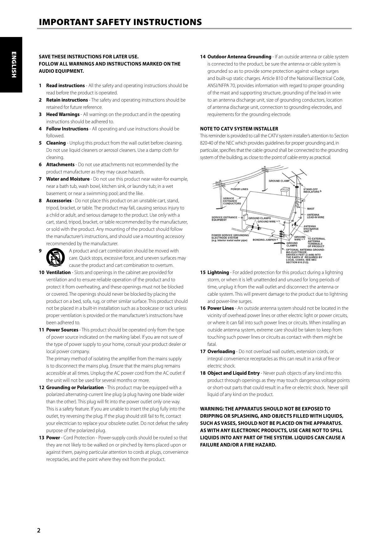
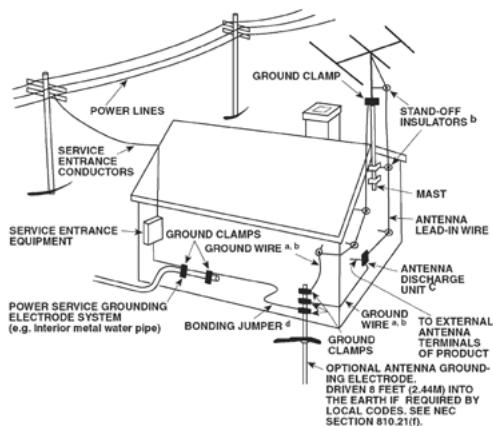
14 Outdoor Antenna Grounding - If an outside antenna or cable system is connected to the product, be sure the antenna or cable system is grounded so as to provide some protection against voltage surges and built-up static charges. Article 810 of the National Electrical Code, ANSI/NFPA 70, provides information with regard to proper grounding of the mast and supporting structure, grounding of the lead-in wire to an antenna discharge unit, size of grounding conductors, location of antenna discharge unit, connection to grounding electrodes, and requirements for the grounding electrode.
NOTE TO CATV SYSTEM INSTALLER
This reminder is provided to call the CATV system installer's attention to Section 820-40 of the NEC which provides guidelines for proper grounding and, in particular, specifies that the cable ground shall be connected to the grounding system of the building, as close to the point of cable entry as practical.
15 Lightning - For added protection for this product during a lightning storm, or when it is left unattended and unused for long periods of time, unplug it from the wall outlet and disconnect the antenna or cable system. This will prevent damage to the product due to lightning and power-line surges.
16 Power Lines - An outside antenna system should not be located in the vicinity of overhead power lines or other electric light or power circuits, or where it can fall into such power lines or circuits. When installing an outside antenna system, extreme care should be taken to keep from touching such power lines or circuits as contact with them might be fatal.
17 Overloading - Do not overload wall outlets, extension cords, or integral convenience receptacles as this can result in a risk of fire or electric shock.
18 Object and Liquid Entry - Never push objects of any kind into this product through openings as they may touch dangerous voltage points or short-out parts that could result in a fire or electric shock. Never spill liquid of any kind on the product.
WARNING: THE APPARATUS SHOULD NOT BE EXPOSED TO DRIPPING OR SPLASHING, AND OBJECTS FILLED WITH LIQUIDS, SUCH AS VASES, SHOULD NOT BE PLACED ON THE APPARATUS. AS WITH ANY ELECTRONIC PRODUCTS, USE CARE NOT TO SPILL LIQUIDS INTO ANY PART OF THE SYSTEM. LIQUIDS CAN CAUSE A FAILURE AND/OR A FIRE HAZARD.
19 Damage Requiring Service - Unplug this product from the wall outlet and refer servicing to qualified service personnel under the following conditions:
a) When the power-supply cord or plug is damaged.
b) If liquid has been spilled, or objects have fallen into the product.
c) If the product has been exposed to rain or water.
d) If the product does not operate normally by following the operating instructions. Adjust only those controls that are covered by the operating instructions as an improper adjustment of other controls may result in damage and will often require extensive work by a qualified technician to restore the product to its normal operation.
e) If the product has been dropped or damaged in any way.
f) when the product exhibits a distinct change in performance-this indicates a need for service.
20 Replacement Parts - When replacement parts are required, be sure the service technician has used replacement parts specified by the manufacturer or have the same characteristics as the original part. Unauthorized substitutions may result in fire, electric shock, or other hazards.
21 Safety Check - Upon completion of any service or repairs to this product, ask the service technician to perform safety checks to determine that the product is in proper operating condition.
22 Wall or Ceiling Mounting - The product should be mounted to a wall or ceiling only as recommended by the manufacturer.
23 Heat - The product should be situated away from heat sources such as radiators, heat registers, stoves or other products (including amplifiers) that produce heat.
WARNING
TO REDUCE THE RISK OF FIRE OR ELECTRIC SHOCK, DO NOT EXPOSE THIS PRODUCT TO RAIN OR MOISTURE.
CAUTION
TO PREVENT ELECTRIC SHOCK, MATCH WIDE BLADE OF PLUG TO WIDE SLOT, FULLY INSERT.
FCC WARNING
Changes or modifications not expressly approved by the party responsible for compliance could void the user's authority to operate the equipment.

THE LIGHTNING FLASH WITH ARROWHEAD SYMBOL, WITHIN AN EQUILATERAL TRIANGLE, IS INTENDED TO ALERT THE USER TO THE PRESENCE OF UNINSULATED "DANGEROUS VOLTAGE" WITHIN THE PRODUCT'S ENCLOSURE THAT MAYBE OF SUFFICIENT MAGNITUDE TO CONSTITUTE A RISK OF ELECTRIC SHOCK TO PERSONS.

THE EXCLAMATION POINT WITHIN AN EQUILATERAL TRIANGLE IS INTENDED TO ALERT THE USER TO THE PRESENCE OF IMPORTANT OPERATING AND MAINTENANCE (SERVICING) INSTRUCTIONS IN THE LITERATURE ACCOMPANYING THE APPLIANCE.

The equipment draws its nominal non-operational power from the AC outlet with its POWER switch in the STANDBY position. The socket-outlet shall be installed near the apparatus and shall be easily accessible.
CAUTION
Changes or modifications to this equipment not expressly approved by NAD Electronics for compliance could void the user's authority to operate this equipment.
CAUTION REGARDING PLACEMENT
To maintain proper ventilation, be sure to leave a space around the unit (from the largest outer dimensions including projections) that is equal to or greater than shown below.
Left and Right Panels: 10 cm
Rear Panel: 10 cm
Top Panel: 50 cm
IMPORTANT INFORMATION FOR UK CUSTOMERS
DO NOT cut off the mains plug from this equipment. If the plug fitted is not suitable for the power points in your home or the cable is too short to reach a power point, then obtain an appropriate safety approved extension lead or consult your dealer. If, nonetheless, the mains plug is cut off, REMOVE THE FUSE and dispose of the PLUG immediately, to avoid possible shock hazard by inadvertent connection to the mains supply. If this product is not provided with a mains plug, or one has to be fitted, then follow the instructions given below:
IMPORTANT
DO NOT make any connection to the larger terminal which is marked with the letter 'E' or by the safety earth symbol or colored GREEN or GREEN AND YELLOW.
The wires in the mains lead on this product are colored in accordance with the following code:
BLUE-NEUTRAL
BROWN-LIVE
As these colors may not correspond with the colored markings identifying the terminals in your plug, proceed as follows:
The BLUE wire must be connected to the terminal marked with the letter 'N' or colored BLACK.
The BROWN wire must be connected to the terminal marked with the letter 'L' or colored RED.
When replacing the fuse, only a correctly rated and approved type should be used, and be sure to re-fit the fuse cover.
IF IN DOUBT CONSULT A COMPETENT ELECTRICIAN.
NOTES ON ENVIRONMENTAL PROTECTION
At the end of its useful life, this product must not be disposed of with regular household waste but must be returned to a collection point for the recycling of electrical and electronic equipment. The symbol on the product, user's manual and packaging, point this out.
The materials can be reused in accordance with their markings. Through re-use, recycling of raw materials or other forms of recycling of old products, you are making an important contribution to the protection of our environment. Your local administrative office can advise you of the responsible waste disposal point.
INFORMATION ABOUT COLLECTION AND DISPOSAL OF WASTE BATTERIES (DIRECTIVE 2006/66/EC OF THE EUROPEAN PARLIAMENT AND THE COUNCIL OF EUROPEAN UNION) (FOR EUROPEAN CUSTOMERS ONLY)
Batteries bearing any of these symbols indicate that they should be treated as "separate collection" and not as municipal waste. It is encouraged that necessary measures are implemented to maximize the separate collection of waste batteries and to minimize the disposal of batteries as mixed municipal waste.
End-users are exhorted not to dispose waste batteries as unsorted municipal waste. In order
to achieve a high level of recycling waste batteries, discard waste batteries separately and properly through an accessible collection point in your vicinity. For more information about collection and recycling of waste batteries, please contact your local municipality, your waste disposal service or the point of sale where you purchased the items.
By ensuring compliance and conformance to proper disposal of waste batteries, potential hazardous effects on human health is prevented and the negative impact of batteries and waste batteries on the environment is minimized, thus contributing to the protection, preservation and quality improvement of the environment.
NOTE: THE C 725BEE IS NOT AN AUTO VOLTAGE RECEIVER. CONNECT ONLY TO THE PRESCRIBED AC OUTLET, I.E., 120V 60HZ OR 230V 50HZ.
RECORD YOUR MODEL NUMBER (NOW,WHILE YOU CAN SEE IT)
The model and serial number of your new C 725BEE are located on the back of the cabinet. For your future convenience, we suggest that you record these numbers here:
Model no:
Serial no:
IMPORTANT SAFETY INSTRUCTIONS 2
INTRODUCTION
GETTING STARTED 6
UNPACKING AND SETUP .6
CHOOSING A LOCATION .6
NOTES ON INSTALLATION .6
ABOUT THE C 725BEE. .6
IDENTIFICATION OF CONTROLS
FRONT PANEL 7
REAR PANEL .9
REMOTE CONTROL 11
USING THE SR 8 REMOTE CONTROL 11
USING THE ZR 5 REMOTE CONTROL. 13
OPERATION
LISTENING TO AM/FM RADIO 14
ABOUT ANTENNAS. 14
TUNING STATIONS. 15
SETTING RADIO PRESETS (AM/FM/DAB). 15
CHOOSING TUNER MODE. 16
ABOUT USER NAMES. 16
ABOUT RDS. 16
THANK YOU FOR CHOOSING NAD.
The C 725BEE Stereo Receiver is a technologically advanced and highly capable product — yet we have invested great effort in making it simple and easy to use. We have been careful to ensure that the C 725BEE is as musically transparent and spatially accurate as possible, incorporating much of what we've learned from a quarter-century's experience designing audio, video and home-theater components.
As with all our products, NAD's "Music First" design philosophy guided the C 725BEE's design in such a way that it can confidently promise you state-of-the-art audiophile-quality music listening for years to come.
LISTENING TO DAB RADIO 17
ABOUT DAB RADIO (230V VERSION ONLY) 17
CONNECTING THE DAB MODULE 17
DAB OPERATION 17
SERVICE LIST 17
DAB TUNER MODE 17
STATION ORDER. 18
DRC 18
MANUAL SCAN. 18
PRUNE LIST. 18
RESET 18
INFORMATION SETTINGS. 19
LISTENING TO YOUR iPod PLAYER.. 20
CONNECTING THE OPTIONAL "NAD IPD 1 DOCK WITH
iPod" AND iPod PLAYER TO THE C 725BEE. 20
iPod MENU OPTIONS. 20
CONTROL FEATURES 21
REFERENCE
TROUBLESHOOTING 22
SPECIFICATIONS 23
We encourage you to take a few minutes now to read right through this manual. Investing a little time here at the outset might save you a good deal of time later and is by far the best way to ensure that you make the most of your investment in the C 725BEE.
One more thing: We urge you to register your C 725BEE ownership on the NAD Worldwide Web site:
http://NADelectronics.com/warranty
For warranty information contact your local distributor.
GETTING STARTED
UNPACKING AND SETUP
WHAT'S IN THE BOX
Packed with your C 725BEE you will find:
The SR 8 remote control with 2 (two) AAA batteries
- ZR 5 zone remote control with 3V CR2025 battery
This owner's manual
SAVE THE PACKAGING
Please save the box and all of the packaging in which your C 725BEE arrived. Should you move or otherwise need to transport your C 725BEE, this is by far the safest container in which to do so. We've seen too many otherwise perfect components damaged in transit for lack of a proper shipping carton, so please: Save that box!
CHOOSING A LOCATION
Choose a location that is well ventilated (with at least several inches to both sides and behind), and that will provide a clear line of sight, within 23 feet/7 meters, between the C 725BEE's front panel and your primary listening/viewing position - this will ensure reliable infrared remote control communications. The C 725BEE generates a modest amount of heat, but nothing that should trouble adjacent components.
NOTES ON INSTALLATION
Your C 725BEE should be placed on a firm, level surface. Avoid placing the unit in direct sunlight or near sources of heat and damp. Allow adequate ventilation. Do not place the unit on a soft surface like a carpet. Do not place it in an enclosed position such a bookcase or cabinet that may impede the air-flow through the ventilation slots.
Make sure the unit is switched off before making any connections.
The RCA sockets on your C 725BEE are color coded for convenience. Red and white are Right and Left audio respectively.
Use high quality leads and sockets for optimum performance and reliability. Ensure that leads and sockets are not damaged in any way and all sockets are firmly pushed home.
For best performance, use quality speaker leads of 16 gauge (1.5mm) thickness or more.
If you intend not to use the C 725BEE for long periods of time, switch OFF the rear panel POWER switch.
Should water get into your C 725BEE, shut off the power to the unit and disconnect the plug from the AC wall outlet. Have the unit inspected by a qualified service technician before attempting to use it again.
DO NOT REMOVE THE COVER; THERE ARE NO USER-SERVICEABLE PARTS INSIDE.
Use a dry soft cloth to clean the unit. If necessary, lightly dampen the cloth with soapy water. Do not use solutions containing benzol or other volatile agents.
ABOUT THE C 725BEE
Though the C 725BEE is among the most technically sophisticated Stereo Receivers, we worked hard to make it one of the most musically transparent components available as well. This is what we mean by NAD's "Music First" design philosophy. Here are just a few examples
- The C 725BEE uses NAD's proprietary Power Drive™ amplifier technology for all channels to preserve accurate, linear reproduction regardless of the loudspeaker. This uniquely efficient power-supply topology provides the real-world benefits of high dynamic power that remains uncompromised by low-impedance speakers. By adding a second high-voltage rail to our well-regulated high-current power supply, we get an "overdrive" that can nearly double the continuous power on a short term dynamic power basis. The result is dynamic, detailed, "un-receiver-like" sound in stereo mode. NAD's exclusive Soft Clipping™ circuitry further enhances sound quality and dynamic potential.
- High-performance components used throughout the receiver's analog audio circuits to maximize quality from all sources.
- Preamp output and main-amp input jacks make potential expansion as flexible as possible.
A Second set of Speaker terminals (Speakers B) for remote listening. - An RS-232 port for advanced zone control and software update through a Windows® compatible PC.
- Gold-surfaced connectors are employed throughout to ensure maximum signal integrity.
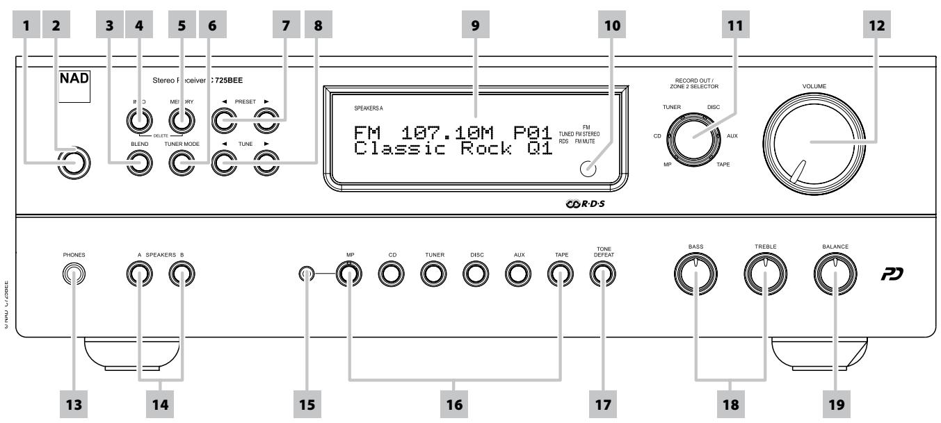
1 STANDBY: With the rear panel POWER switch set to ON position, press this button to switch ON the C 725BEE from standby mode. The Standby LED indicator will turn from amber to blue and illuminate the VFD. Pressing the [Standby] button again turns the unit back to standby mode.
The C 725BEE can also be switched ON from standby mode by pressing any of the front panel buttons.
2 STANDBY LED: This indicator will light up amber when the C 725BEE is in standby state. When the C 725BEE is at ON state, this indicator will illuminate blue. When infrared command from the SR 8 is received, this indicator will also flash momentarily.
In cases of serious abuse of the C 725BEE, such as excessively low loudspeaker impedance and short circuit, the C 725BEE will engage its Protection circuitry, indicated by the Standby LED turning from blue to red and the sound being muted. At Protect mode, the Standby LED in red color will flash and "Protect!" shown flashing also in the VFD. In the case of overheating, the Standby LED in red color will flash and the VFD turned off.
In such a case, turn the C 725BEE off by the rear panel POWER button, wait for it to cool down and/or check the speaker connections, making sure the overall loudspeaker impedance doesn't go below 4 ohms. Once the cause for the protection circuitry to engage has been removed, switch ON the rear POWER button and the Standby Button to resume normal operation.
3 BLEND:The NAD BLEND feature will allow you to reduce the amount of noise and hiss but still retain some level of stereo separation, instead of mono.The BLEND button toggles between engaging and disengaging the BLEND feature.When engaged, "Blend On"is shown at the lower line of the VFD; "Blend Off"when not active. The"Blend On"or"Blend Off" status can be stored for individual presets.
4 INFO: Toggle this button for the lower line of the VFD to show various settings, conditions and other information relevant to the currently tuned station or broadcast.
5 MEMORY: Press this button to store tuned AM, FM and digital radio stations to the C 725BEE's 40 preset-memory locations. One can store a mix of any AM, FM and DAB broadcasts to the 40 available presets.
In combination with [INFO] button, [MEMORY] button is also used in deleting stored presets. Press and hold [INFO] button and then press [MEMORY] - current stored preset setting will be erased. Refer also to the item about SETTING RADIO PRESETS at the LISTENING TO AM/FM RADIO section of the OPERATION page.
6 TUNER MODE: In FM mode, toggle this button to switch between "FM Mute On" (stereo) and "FM Mute Off" (mono). Select "FM Mute Off" for stations that have too much interference or are too weak. When engaged, "FM Mute On" is shown at the lower line of the VFD; "FM Mute Off" when not active. The "FM Mute On" or "FM Mute Off" status can be stored for individual presets. Refer also to the item about CHOOSING TUNER MODE at the LISTENING TO AM/FM RADIO section of the OPERATION page.
In DAB mode, pressing this button will activate Dynamic Range Control (DRC), Station Order or other applicable DAB menu options. Refer also to the item about DAB TUNER MODE at the LISTENING TO DAB RADIO section of the OPERATION page.
7 PRESET [</▶]: Press to step up or down between stored radio presets; 40 presets are available. Note that this function "wraps": Pressing [PRESET </▶] will step from Preset 1 to Preset 40 or vice versa. "Unused" presets are skipped over.
8 TUNE [</▶]: Toggle either button to step up or down between AM or FM frequencies. Press and release [TUNE </▶] to search up or down - the C 725BEE will stop at the next sufficiently strong signal it encounters. Note that this function "wraps" - that is, it will continue to search from one end of the AM or FM band to the other until it stops at a strong signal. Pressing [TUNE </▶] during the search process will stop the search. Refer also to "OPERATION - LISTENING TO DAB RADIO" for [TUNE </▶] usage in DAB operation.
9 VACUUM FLUORESCENT DISPLAY (VFD): Provide visual information about the unit's important modes, settings, functions, status of the current source and other indicators. When in tuner mode, it displays information about the current station or broadcast as supplied by the service provider among other tuner settings.
FRONT PANEL
10 REMOTE SENSOR: Point the SR 8 remote control at the remote sensor and press the buttons. Do not expose the remote sensor of the C 725BEE to a strong light source such as direct sunlight or illumination. If you do so, you may not be able to operate the C 725BEE with the remote control.
Distance: About 23ft (7m) from the front of the remote sensor.
Angle: About 30o in each direction of the front of the remote sensor.
11 RECORD OUT/ZONE 2 SELECTOR: This knob doubles as both a record and zone source selector. Rotate knob and select the Source you would like to be directed out to REC OUT/ZONE 2 output port in the rear panel. The directed Source signal at the REC OUT/ZONE 2 output port could be used for making audio recordings or as an audio input to a separate zone in your home.
ABOUT ZONE FEATURE
The Zone feature allows one to simultaneously listen to another active Source of the C 725BEE that is different from the currently selected Source. For example, while the C 725BEE is at CD mode, you can set the RECORD OUT/ZONE 2 SELECTOR knob to "TUNER" and the active tuned station's audio will be directed to REC OUT/ZONE 2 output port in the rear panel.
You can then feed the REC OUT/ZONE 2 jack to another amplifier or receiver that is located maybe in another area of your home or building. With your separate amplifier or receiver selecting the fed signal and with speakers connected, you can then enjoy listening to the tuned station. You can vary the level of the tuned station by adjusting the Volume control of the separate amplifier or receiver. Refer also to the item USING THE ZR 5 REMOTE CONTROL at the REMOTE CONTROL section of the the IDENTIFICATION OF CONTROLS page.
12 VOLUME: The VOLUME control adjusts the overall loudness of the signals being fed to the loudspeakers or headphones. Turn clockwise to increase the volume setting; counter clockwise to lower it. The VOLUME control does not affect recordings made using the REC OUT/ZONE 2 output but will affect the signal going to the Pre-amp output (PRE OUT).
NOTE
If the Volume level is adjusted using the SR 8's [VOL I V ] buttons, the lower line of the VFD will show "Volume Up" when level is increased or "Volume Down" if level is decreased.
13 PHONES: A 1/4" stereo jack socket is supplied for headphone listening and will work with conventional headphones of any impedance. The headphone socket will work in parallel to the selected speakers. To listen to headphones only, de-select Speakers A and/or B. The volume, tone and balance controls are operative for headphone listening. Use a suitable adapter to connect headphones with other types of sockets, such as 3.5mm "personal stereo" jack plugs.
NOTE
Make certain that the volume control is turned to minimum (fully counter-clockwise) before connecting or disconnecting headphones. Listening at high levels can damage your hearing.
14 A SPEAKERS B: The SPEAKERS A and B buttons engage or disengage the speakers connected respectively to the SPEAKERS A and SPEAKERS B terminals on the rear panel. Press "A" to switch ON or OFF the speakers connected to the SPEAKERS A terminals. Press "B" to switch ON or OFF the speakers connected to the SPEAKERS B terminals.
15 MP SOCKET: Using a 3.5mm stereo plug, connect into this socket the audio output of a Media Player. The LED on the MP input button will illuminate when an external Media Player is connected to this socket.
16 INPUT SELECTORS: These buttons select the active input to the NAD C 725BEE and the signal sent to the loudspeakers, headphones and the PRE OUT socket. The buttons on the remote control handset duplicate these buttons. The selected input will be displayed in the VFD.
MP (MEDIA PLAYER): Selects a line-level source connected to the MP sockets as the active input. If the DATA port of the optional NAD IPD 1 Dock with iPod (NAD IPD 1) is connected to the corresponding DATA PORT in the rear panel, your iPod player docked and with the NAD IPD 1's AUDIO OUT also connected to the rear panel MP input, the lower line of the VFD will show "iPod Connected". Refer also to LISTENING TO YOUR iPod PLAYER under the OPERATION main heading. If an external Media Player is connected to the front MP socket (using a 3.5mm stereo plug) while listening to a MP line-level source, the external Media Player will be directly selected with the MP line-level source immediately disconnected. It is recommended to mute the volume or switch to a different input before plugging/unplugging the external Media Player cable.
CD: Selects the CD (or other line-level source) connected to the CD sockets as the active input.
TUNER: Toggle to select AM, FM or DAB (230V version only) tuner band.
DISC: Selects a line-level source connected to the DISC sockets as the active input.
AUX: Selects a line-level source connected to the AUX sockets as the active input.
TAPE: Selects the Tape (or other line-level source) connected to the TAPE sockets as the active input.
17 TONE DEFEAT: Tone Controls are enabled or disabled by pressing this button. The lower line of the VFD will show "Tone Defeat" when the tone controls are bypassed or "Tone Active" if the tone controls are enabled.
18 TONE CONTROLS: The NAD C 725BEE is fitted with BASS and TREBLE tone controls to adjust the tonal balance of your system. The 12 o'clock position is "flat" with no boost or cut, and an indent indicates this position. Rotate the control clockwise to increase the amount of Bass or Treble. Rotate the control counterclockwise to decrease the amount of Bass or Treble. The Tone controls do not affect recordings made using the REC OUT/ZONE 2 output but will affect the signal going to the Pre-amp output (PRE OUT).
19 BALANCE: The BALANCE control adjusts the relative levels of the left and right speakers. The 12 o'clock position provides equal level to the left and right channels. A detent indicates this position. Rotating the control clockwise moves the balance towards the right. Rotating the control counterclockwise moves the balance to the left. The BALANCE control does not affect recordings made using the REC OUT/ZONE 2 output but will affect the signal going to the Pre-amp output (PRE OUT).
ATTENTION!
Please make sure that the C 725BEE is powered off or unplugged before making any connections. It is also advisable to power-down or unplug all associated components while making or breaking any signal or AC power connections.
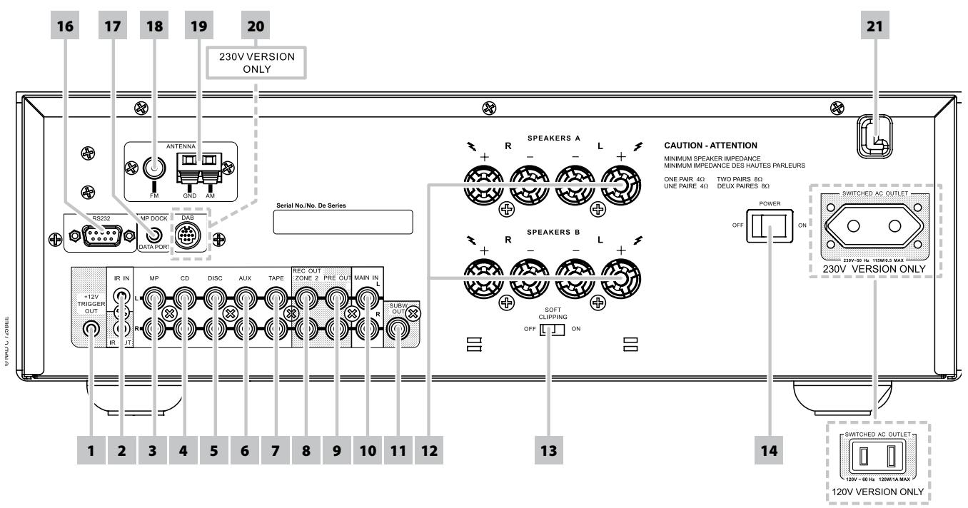
1 +12V TRIGGER OUT: The +12V TRIGGER OUT is used for controlling external equipment that is equipped with a +12V trigger input. This output will be 12V when the C 725BEE is ON and 0V when the unit is either OFF or in standby. This output can drive a load up to 150mA at 12V.
2 IR IN/OUT: These mini-jacks accept and output remote-controlled codes in electrical format, using industry-standard protocols, for use with "IR-repeater" and multi-room systems and related technologies.
IR IN: This input is connected to the output of an IR (infrared) repeater (Xantech or similar) or the IR output of another component to allow control of the C 725BEE from a remote location.
IR OUT: When connected to the IR IN of an ancillary equipment, direct the ancillary equipment's own remote control to the C 725BEE's infrared receiver to command or control the linked unit.
All NAD products with IR IN/IR OUT features are fully compatible with the C 725BEE. For non-NAD models, please check with your other product's service specialists as to their compatibility to the C 725BEE's IR features.
3 MP INPUT: Input for a Media Player or other line-level signal source. Use a twin RCA-to-RCA lead to connect the Media Player's left and right "Audio Outputs" to this input. The MP input is also the assigned port where the optional NAD IPD 1's AUDIO OUT could be connected.
With the NAD IPD 1's DATA PORT connected to the corresponding rear panel's DATA PORT socket, your iPod player docked in the NAD IPD 1 and the C 725BEE set to "MP" mode, you can start listening to your iPod's playlist. Refer also to LISTENING TO YOUR iPod PLAYER under the OPERATION main heading.
4 CD INPUT: Input for a CD or other line-level signal source. Use a twin RCA-to-RCA lead to connect the CD player's left and right "Audio Outputs" to this input.
5 DISC INPUT: Input for additional line level input signals such as CD, Mini Disc player or the output signal from a step-up amplifier for a turntable. Use a twin RCA-to-RCA lead to connect the auxiliary unit's left and right "Audio Outputs" to this input.
6 AUX INPUT: Input for additional line level input signals such as another CD player. Use a twin RCA-to-RCA lead to connect the auxiliary unit's left and right 'Audio Outputs' to this input.
7 TAPE: Connections for audio tape recorder playback of any type. Using twin RCA-to-RCA leads, connect to the left and right "Audio Output" of the tape machine to the TAPE sockets for playback.
8 REC OUT/ZONE 2: Doubles as both a RECORD and ZONE output port. As a RECORD output, the Source signal directed to this output could be used for making audio recordings. As a Zone output, it sends zone selected audio sources to the corresponding audio input of another separate zone. Use high quality patch cables to reduce noise pickup over long distance runs.
9 PRE OUT: Connections to an external power amplifier or processor, such as a surround-sound decoder. In normal use, this should be connected to the Main In sockets (No. 10) with the links supplied. To connect your NAD C 725BEE to external processor or amplifier sections, remove first these links. Use a twin RCA-to-RCA lead to connect the left and right "Audio Input" of a power amplifier or processor to the PRE OUT sockets.
NOTE
Always turn the C 725BEE and associated external power amplifiers OFF before connecting or disconnecting anything to the PRE OUT and MAIN IN sockets. The PRE OUT output signal will be affected by the C 725BEE's volume and tone control settings.
REAR PANEL
10 MAIN IN: Connections to an external pre-amplifier or processor, such as a surround-sound decoder. In normal use, this should be connected to PRE OUT sockets (No. 9) with the links supplied. To connect your NAD C 725BEE to external processor or pre-amplifier, remove first these links. Use a twin RCA-to-RCA lead to connect the left and right "Audio Output" of the pre-amp or processor to the Main In sockets.
NOTE
Always turn the C 725BEE off before connecting or disconnecting anything from to PRE OUT and MAIN IN sockets.
11 SUBW (SUBWOOFER) OUT: Connect this output to a powered (active) subwoofer or to a power amplifier channel driving a passive system.
12 SPEAKERS A, B: The C 725BEE is equipped with two sets of speaker connectors. Use the Speakers A terminals for the "main" speakers and use the Speakers B terminals for a second pair, for example, extension speakers located in another room.
Connect the right speaker to the terminals marked R + and R- ensuring that the R+ is connected to the ^+ terminal on your loudspeaker and the R- is connected to the loudspeaker's -terminal. Connect the terminals marked L+ and L- to the left speaker in the same way.
The C 725BEE is designed to produce optimum sound quality when connected to speakers with impedances within its operating range. Please make sure that all the speakers are rated 4 ohms minimum per speaker.
NOTE
Use stranded wire of at least 16 gauge (AWG); specialized speaker cable maybe valuable (consult your NAD audio specialist). Connections to the C 725BEE can be made with banana plugs (120V version only) or by using bare wire or pins. Use the transverse hole through the post for bare-wire or pin connections. By loosening the terminal's plastic nut, make a clean, neat connection and re-tighten carefully. To minimize the danger of short-circuit, ensure that only 1/2-inch of exposed wire or pin is employed when connecting.
13 SOFT CLIPPING™: Enables NAD's proprietary Soft Clipping circuitry on all channels. At ON position, Soft Clipping gently limits the output of the C 725BEE to minimize audible distortion should the Receiver be overdriven. Soft Clipping may simply be left ON ("S.CLIP" icon will illuminate in the VFD) at all times to reduce the likelihood of audible distortion from excessive volume settings. However, for critical listening and to preserve optimum dynamics, you may wish to defeat it by setting this switch OFF.
14 POWER SWITCH: The POWER switch supplies the master AC mains power for the C 725BEE. When this switch is at ON position, the C 725BEE is in standby mode as shown by the amber status condition of the standby LED. If you intend not to use the C 725BEE for long periods of time (such as when on vacation), switch the POWER switch to the OFF position. When the POWER switch is at OFF position, the front panel power button, SR 8 remote control or ZR 5 cannot activate the C 725BEE.
15 SWITCHED AC OUTLET: This convenience outlet can supply switched power to another component or accessory. With the Power switch at the rear panel set to ON position, this outlet is powered ON or OFF by the front panel STANDBY switch or by the SR 8's [ON/OFF] buttons. The total draw of all devices connected to this outlet must not exceed 120 watts for 120V version and 115 watts for 230V version.
16 RS-232: Connect this interface via RS-232 serial cable (not supplied) to any Windows® compatible PC to allow remote control of the C 725BEE through NAD's proprietary PC software or other compatible external controllers. NAD is a certified partner of AMX and Crestron and fully supports these external devices. See your NAD audio specialist for more information.
17 MP DOCK: The C 725BEE is equipped with a data port in the rear panel where an optional "NAD IPD 1 Dock with iPod" (NAD IPD 1) can be plugged in. Connect the "MP DOCK (DATA PORT)" jack of the C 725BEE to the corresponding "DATA PORT" socket of the optional NAD IPD 1. Refer also to LISTENING TO YOUR iPod PLAYER under the OPERATION main heading.
NOTE
C 725BEE is compatible with NAD IPD 1 and later NAD IPD variants. Check with your dealer or NAD audio specialist for other versions of NAD IPD compatible with C 725BEE.
18 FM ANTENNA INPUT: The supplied wire "dipole"FM antenna will connect to the FM connector using the supplied "balun"adapter. It will usually work best when mounted on a vertical surface such as a wall, with arms fully outstretched forming a horizontal "T" perpendicular to the origin point of the signal. Refer also to the item ABOUT ANTENNAS at the LISTENING TO AM/FM RADIO section of the OPERATION page.
19 AM ANTENNA INPUT: Connect the supplied AM loop antenna to these terminals. If an external AM antenna is used, make connections to the AM and GND terminals in accordance with the instructions supplied with the antenna. Refer also to the item ABOUT ANTENNAS at the LISTENING TO AM/FM RADIO section of the OPERATION page.
20 DAB MODULE INPUT PORT (230V version only): Plug-in the other end of the Mini-Din connector from the NAD DAB Adaptor DB 1 module output port into this socket. The C 725BEE is compatible only with NAD DAB Adaptor DB 1 so check with your NAD dealer for this module's availability. With DAB, you can receive CD-like quality programs without any annoying interference and signal distortion. Refer also to "LISTENING TO DAB RADIO" under the "OPERATION" main heading.
21 AC LINE CORD: Plug the AC power cord into a live AC wall socket. Connect only to the prescribed AC Outlet, i.e., 120V 60 Hz or 230V 50 Hz. Make sure all connections have been made before connecting to mains.
USING THE SR 8 REMOTE CONTROL
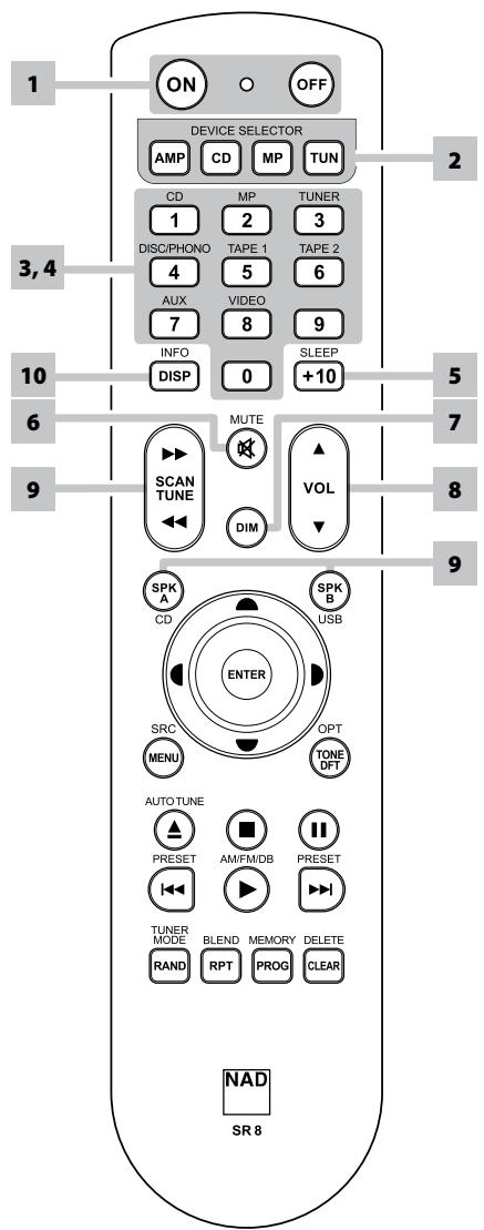
The SR 8 remote control handset handles the key functions of the C 725BEE as well as other NAD Stereo Receivers, Integrated Amplifiers and Preamplifiers. It has additional controls to remotely operate NAD CD Players, AM/FM Tuners and dedicated AM/FM/DAB Tuners. It will operate up to a distance of 23ft (7m). Alkaline batteries are recommended for maximum operating life. Two AAA batteries should be fitted in the battery compartment at the rear of the Remote Control handset. When replacing batteries, check that they have been put in the right way round, as indicated on the base of the battery compartment.
When a command from the remote control is received, the Standby LED indicator will blink. Note that the indicator may also blink when receiving commands not necessarily for the C 725BEE but for other components in the system. Please refer to previous sections of the manual for a full description of individual functions.
NOTE
The remote control handset supplied with the C 725BEE is of a universal NAD type, designed to operate several NAD models. Some buttons are applicable only to specific NAD models. Contact your dealer or NAD audio specialist for assistance.
1 POWER ON & OFF: The SR 8 remote has a separate ON and OFF button. Press the ON button to switch the unit from Standby to operating mode. Press the OFF button to switch the unit to Standby mode.
2 DEVICE SELECTOR: A Device Selector button determines only what component the SR 8 will command; it does not perform any function on the receiver. Press desired Device Selector button for the applicable buttons to be directed to a "page" of commands relevant to the selected device. Upon selecting a Device, you can now press the corresponding SR 8 control buttons applicable for the selected Device.
3 INPUT SELECTORS: Refer to the corresponding labels printed in the remote control faceplate and their respective assigned buttons to make use of these functions. Set the DEVICE SELECTOR to "AMP" in order to gain access to these buttons. The input selector buttons perform the same functions as the buttons labeled the same on the front panel.
4 NUMERIC KEYS: The numeric keys allow for direct input of tracks for CD players, and direct channel/preset access for tuners and receivers.
5 SLEEP: Switch off the NAD Receiver or Tuner after a preset number of minutes.
SLEEP MODE
The Sleep Mode timer will switch the C 725BEE to Standby mode automatically after a preset number of minutes. Pressing the SR 8's [SLEEP] button once will display the setting of the sleep time increment. Pressing the SR 8's [SLEEP] button a second time within a 3-second period will change the sleep time increment in 15-minute intervals, after which time the C 725BEE will automatically switch into Standby mode.
To adjust the sleep delay, press the SR 8's [SLEEP] button twice; first to display the sleep time increment, and a second time to change the sleep time increment. The sleep time increment and a "SLEEP" icon will continuously display on the C 725BEE's front panel Vacuum Fluorescent Display (VFD). Each consecutive press increases the sleep time in 15-minute increments from 15 to 90 minutes. To cancel the sleep mode, continue pressing the SR 8's [SLEEP] button until "Sleep Off" displays on the VFD. Switching the C 725BEE to standby from either the SR 8's OFF or the C 725BEE's Standby button will also cancel the sleep mode.
6 MUTE: Press the [MUTE] button to temporarily switch OFF the sound to the speakers and headphones. MUTE mode is indicated by the Standby LED indicator flashing for NAD Integrated Amplifiers or "Mute" shown in the VFD of NAD Receivers. Mute does not affect recordings made using the TAPE or RECORD OUT/ZONE 2 outputs but will affect the signal going to the PRE OUT outputs (if applicable). Press MUTE again to restore sound or by pressing [VOL▲/▼] of SR 8.
7 DIM (for use with NAD Stereo Receiver, Tuner and CD Player): Reduce, turn off or restore VFD brightness. Depending on the NAD model, the brightness of the front panel display will vary when you toggle this button.
REMOTE CONTROL
8 VOL [ / ] : Press [ / ] button to increase or decrease the loudness level. Release the button when the desired level is reached. The VFD on the front panel will indicate the level set. For NAD Receivers, the VFD will also show "Volume Up" or "Volume Down" while pressing SR 8's. The VOLUME buttons do not affect recordings made using the TAPE or RECORD OUT/ZONE 2 outputs but will affect the signal going to the PRE OUT outputs (if applicable).
9 SPKA, SPKB: The [SPK A] and [SPKB] buttons engage or disengage the speakers connected respectively to the Speakers A and Speakers B terminals. Toggle [SPKA] to switch ON or OFF the speakers connected to the Speaker A terminals. Toggle [SPKB] to switch ON or OFF the speakers connected to the Speaker B terminals. Press both buttons to engage both speakers.
10 TONE DFT: Tone Controls are enabled or disabled by pressing this button.
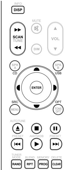
CD PLAYER CONTROL (for use with NAD CD Player): Set the DEVICE SELECTOR to "CD" in order to gain access to these buttons. Some of the control buttons below are applicable only to specific NAD CD Player models; check the owner's manual of your NAD CD Player for control button compatibility.
SCAN[</>>]:Fast reverse/forward search.
[▲]: Open or close disc tray.
[■]:Stop playback.
[II]: Pause playback temporarily.
[▶▶]: Go to next track/file.
[1]: Go to beginning of current track/file or to previous track/file.
[▶]: Start playback.
FOLDER/FIELE [▲/▼]: Select through folder list/Select through WMA/MP3 files.
ENTER: Select desired folder or WMA/MP3 file.
DISP: Show playback time and other display information.
RAN: Play tracks/files in random order.
RPT: Repeat track, file or whole disc.
PROG: Enter or exit program mode.
CLEAR: Delete programmed track/file.
CD: Select CD as the active source.
USB: Select USB as the active source.
OPT: Select optical input as the active source.
SRC: Toggle to select desired SRC mode.
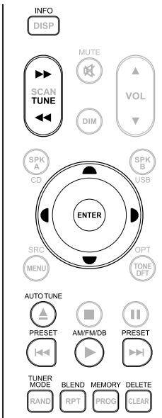
TUNER CONTROL (for use with NAD AM/FM/DAB Tuner): Set the DEVICE SELECTOR to "TUN" in order to gain access to these buttons. Refer to the corresponding labels printed in the remote control faceplate and their respective assigned buttons to make use of these functions. Some of the control buttons below are applicable only to specific NAD Receiver or Tuner models; check the owner's manual of your NAD Receiver or Tuner for control button compatibility.
AUTO TUNE: In DAB mode, press this button to automatically scan all available local stations.
TUNE [ / ] or [ / ] : Step up or down between AM or FM frequencies.
PRESET [I<\triangleright] or [A/\triangledown]: Step up or down between stored radio presets.
AM/FM/DAB: Select DAB, FM or AM band.
TUNER MODE: In FM mode, toggle between "FM Mute On" and "FM Mute Off". In DAB mode, pressing this button will activate Dynamic Range Control (DRC), Station Order or other applicable DAB menu options.
BLEND: Engage or disengage BLEND feature.
MEMORY: Save current station into preset memory.
DELETE: Press and hold for about 2 seconds and the selected preset memory is erased.
[▲/▲]: In DAB mode, in combination with TUNER MODE or other compatible buttons, toggle to select through DAB feature options like Dynamic Range Control, Station Order and other appropriate DAB options.
ENTER: In AM/FM mode, toggle to select Preset or Tune mode. In DAB mode, press and hold to check signal strength.
INFO: Repeatedly pressing this button will show information as supplied by the current radio station. The applicable display contents include related DAB display information and RDS broadcast data.
NOTE
For iPod player-specific control buttons, please refer to "CONTROL FEATURES" under "OPERATION - LISTENING TO YOUR iPod PLAYER".
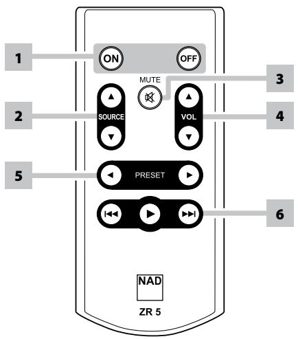
USING THE ZR 5 REMOTE CONTROL
The ZR 5 remote control is a discrete compact remote for controlling the C 725BEE from various rooms other than the main room. The ZR 5 remote allows full separate control of the source selection irrespective of the main room. This means the zone input may be completely different audio from the main input.
1 ON/OFF: Switch ON/OFF the Zone feature. When OFF, the active RECORD OUT/ZONE 2 Selector LED will be extinguished.
2 SOURCE[▲/▼]: Select the active input of the NAD C 725BEE that will be sent out to the rear panel REC OUT/ZONE 2 output port.
3 MUTE: Temporarily switch OFF or restore the Zone Volume level.
4 VOLUME [ / ] :This function is not applicable for the C 725BEE.
5 PRESET [</▶]: Step up or down between stored radio presets. This control button is possible if the selected Zone is "TUNER" and the active tuner section has stored presets.
6 The following CD Player Zone buttons can control a CD Player linked to the C 725BEE under the following conditions
a The selected zone is "CD".
b An active CD Player with disc loaded is connected to the CD input of the C 725BEE.
SKIP [▶▶I]: Go to the beginning of a track/file or previous track/file.
SKIP [1]: Go to the next track/file.
[▶]: Start playback.
LISTENING TO AM/FM RADIO
The C 725BEE's internal AM/FM tuner offers very high quality sound from radio broadcasts. The reception and sound quality will always be dependent to a degree however on the type of antenna(s) used as well as proximity to the broadcast origin, geography and weather conditions.
ABOUT ANTENNAS
The supplied ribbon-wire FM antenna can be connected to the rear-panel FM-antenna input using the included "balun" adapter and should be fully extended to form a "T". This folded-dipole antenna will usually work best when oriented vertically, with the arms of its "T" fully outstretched and arranged perpendicular to the origin of the desired broadcast. There are no "rules" however, and experimenting freely with antenna placement and orientation may yield the clearest sound and lowest background noise.
In areas of poor FM reception, an exterior FM antenna can improve performance dramatically. If radio listening is important to you, consider consulting an antenna installation professional to optimize your system.
The supplied AM "loop" antenna will usually provide adequate reception. However, an exterior AM antenna can be used to improve reception. Consult an antenna professional for more information.
ASSEMBLING THE LOOP ANTENNA
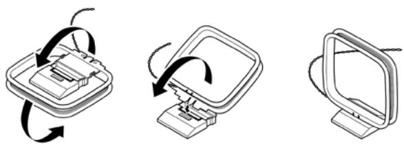
1 Rotate the outer frame of the antenna.
2 Insert the bottom edge of the outer frame into the groove on the stand.
3 Extend the antenna cord.
SELECTING BAND
Press the [TUNER] button on the front panel or on the remote control. Each subsequent press of either key will toggle the unit among AM, FM and DAB radio.
IMPORTANT NOTICE
In the foregoing sections about TUNER features, make sure to set SR 8's DEVICE SELECTOR to "TUN" for the applicable TUNER commands to be effected.
TUNING STATIONS
1 Toggle [TUNE ] on the front panel or remote control to step up or down between AM or FM frequencies.
2 Press and release [TUNE / ] to search up or down - the C 725BEE's tuner will stop at the next sufficiently strong signal it encounters. Pressing the [TUNE / ] during the search process will stop the search.
DIRECT TUNING
If you know your desired station's frequency allocation, you can tune directly to the station.
1 Toggle [ENTER] button to switch between "Preset" and "Tune" mode (see the lower line of the VFD). Select "Tune" mode.
2 Using the numeric keys of the remote control, key-in the frequency allocation of the station and then press [ENTER]. For example, to enter 104.50 MHz, press "1","0","4","5" and "0" or press "1","0","4","5" and [ENTER].
SETTING RADIO PRESETS (AM/FM/DAB)
The C 725BEE can store a mix of your 40 favorite AM, FM and DAB broadcasts for immediate recall.
1 To store a radio preset, first tune the desired frequency (see above), then press the front panel [MEMORY] button. The VFD will show a blinking "MEMORY" icon and the next available vacant Preset number – for example, "Preset __Free" (the two blank spaces will correspond to the preset number that could be from '01' to the maximum of '40').
2 Press [MEMORY] button again to store the desired frequency on the Preset number shown or use the [PRESET ] keys to select another available Preset number.
3 Then, press [MEMORY] key button again. Your desired frequency is now stored in the assigned preset.
The Radio Presets can be stored using the same keys on the front panel or remote control.
RECALLING PRESETS
1 Use the [PRESET ] keys on the front panel to step up or down between presets.
2 Press and hold [PRESET ] to "scroll" continuously up or down.
3 Stop or release the [PRESET ] key while scrolling to select a desired Preset number - the stored station will be recalled after a brief delay; or press [ENTER] to tune immediately to the selected Preset number. Empty presets will be skipped during preset tuning.
The SR 8 remote's [PRESET / ] keys work similarly.
DIRECT RECALL OF A PRESET
You can directly recall a desired Preset number.
1 Toggle SR 8 remote's [ENTER] button to switch between "Preset" and "Tune" mode (see the lower line of the VFD). Select "Preset" mode.
2 Using the numeric keys of the remote control, key-in directly your desired Preset number and then, press [ENTER]. For example, to enter Preset 5, press "5" and then, press [ENTER].
DELETE A PRESET
You can empty a preset by deleting the stored information.
1 Select the Preset number to be deleted.
2 Press and hold [INFO] button and then press [MEMORY] button - current stored preset setting will be erased.
CHOOSING TUNER MODE
The front-panel [TUNER MODE] button is a dual-purpose control. In the normal position ("FM Mute On" is briefly displayed in the lower line of the VFD; "FM STEREO" and "FM MUTE" icons on the VFD are lit), only the stations with a strong signal can be listened to, and the noise between stations is muted.
Pressing the [TUNER MODE] button again ("FM Mute Off" is briefly displayed in the lower line of the VFD; "FM STEREO" and "FM MUTE" icons on the VFD are extinguished) allows distant and potentially noisy stations to be received. Noise is reduced if the FM station signal level is less than the FM Stereo threshold (since mono FM is inherently less noise-prone) though at the sacrifice of the stereo effect.
NOTE
One can store the same channel in two preset locations - one with "FM Mute Off" and another with "FM Mute On".
ABOUT USER NAMES
You can assign a twelve character "UserID" to each radio preset, which will show in the front-panel readout whenever that preset is recalled.
ENTERING USER NAMES
To name a radio preset "NEWS," follow the procedure as below.
1 Recall the desired radio preset.
2 Then, press the [MEMORY] button once and then within five (5) seconds, press the [INFO] button - the readout shows a blinking box.
3 Use the [PRESET / ] buttons to select the first character of the name ("N" from the alphabetical list).
4 Press [TUNE▶] button to select the character and correspondingly move forward to the next position (Press [TUNE▲] to go back to the previous character). Repeat this process for each character in sequence.
5 Press the [MEMORY] key again to store the User Name and exit the text-entry mode.
ABOUTRDS
The Radio Data System (RDS) permits sending small amounts of digital information using conventional FM radio broadcasts. The C 725BEE supports two RDS modes, station-name (PS mode) and radio-text (RT mode). Not every FM station incorporates RDS in its broadcast signal. In most areas you will find from one to several RDS-enabled stations, but it is by no means impossible that your favorite stations will not be broadcasting RDS data.
VIEW RDS TEXT
When an RDS-enabled FM broadcast is tuned, after a brief delay the lower line of the VFD will show its station-name (PS) text:"ROCK101,"for example.
Toggle the front-panel [INFO] key to scroll among other MODE settings the station's radio-text (RT) readout, if any, which might scroll song or artist name or any other text of the station's choosing.
LISTENING TO DAB RADIO
ABOUT DAB RADIO (230V VERSION ONLY)
Until now, analogue radio signals such as FM or AM have been subject to numerous kinds of interference on their way from the transmitter to your radio. These problems were caused by mountains, high-rise buildings and weather conditions. With Digital Audio Broadcast (DAB), you can now receive CD-like quality radio programs without any annoying interference and signal distortion. DAB broadcasts use digital signals rather than traditional analogue transmissions, thus providing clear high quality reception. You get far more robust reception and virtually hiss or crackle free sound with DAB as long as you are within a good coverage area.
With DAB, the listener can scroll through a list of available stations - then instantly tune to the station of his choice. There is no need either to remember channel frequencies. All broadcasts are selected by simply selecting the service name.
The C 725BEE makes it possible for you to enjoy listening to DAB broadcasts. The C 725BEE has a Digital Audio Broadcast (DAB) module socket on the rear panel for adding a separately sold and NAD-specified outboard DAB module – the NAD DAB Adaptor DB 1. All the control software for this format is included; just plug-in the module and start enjoying the CD-like quality sound and expansive content selection available with DAB.
CONNECTING THE DAB MODULE
Plug-in the other end of the DIN connector (supplied with your NAD DAB Adaptor DB 1) from the DAB module's output port into the corresponding DAB module input socket on the rear panel of the C 725BEE. Select DAB mode on the C 725BEE by toggling the [TUNER] button in the front panel or SR 8's [TUN] button.
NOTES
- Please refer to NAD DAB Adaptor DB 1 installation guide for proper setup connection of the DB1 with respect to the C 725BEE.
- If there is no NAD DAB Adaptor DB 1 connected, the VFD will show "Check DAB Tuner."
DAB OPERATION
With the separately sold NAD DAB Adaptor DB1 already connected to the C 725BEE, you can now carry out the C 725BEE to receive DAB broadcasts.
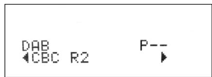
1 Toggle [TUNER] button until DAB mode. The VFD will show "No Service List" indicating that there are no scanned DAB broadcast services yet. This is the default mode of the DB1.
DAB P-- No Service List
2 To tune to DAB broadcast services, press [TUNER MODE] and then toggle the front panel's [TUNE ] to select either "Full Scan" or "Local Scan". FULL SCAN will enable the scanning of the full range of digital frequencies (Band III and L-Band).
LOCAL SCAN performs local scanning of available DAB services in your area. Check with your dealer or visit www.WorldDAB.org to check the applicable digital transmission frequencies in your area.
3 Upon selecting either "Full Scan" or "Local Scan", press SR 8's [ENTER] button. Automatic scanning will ensue. This sequence cannot be interrupted.
During the sequence, the following message will be visible in the VFD.
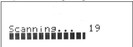
The bars show the progress of the sequence. When scanning is completed, the last number shown on the right side of the VFD corresponds to the total number of DAB broadcast stations found. Then, the first station is tuned in (See "ALPHANUMERIC" section below to understand the order or arrangement of stations).
4 Press and hold SR 8's [ENTER] button - the signal strength of the currently tuned broadcast will be shown on the VFD. The more segments visible in the lower display line, the stronger the signal. By changing the position of the antenna, you can increase the signal strength. You can also opt for an external antenna. Consult an antenna professional for more information. Press SR 8's [ENTER] button to exit Signal Strength check.

NOTES
- "No Service List" will also be shown in the VFD when no stations are found after the scanning process. If this occurs, check the connection and position of the DAB antenna or call your local DAB broadcast providers for coverage information.
- SR 8's [TUNER MODE] and [▲/▲] are the equivalent remote control keys for the front panel buttons [TUNER MODE] and [TUNE▲/▲]. When using these SR 8 buttons to navigate DAB options, ensure that the "DEVICE SELECTOR" setting of your SR 8 is set to "TUN".
- Front panel's [TUNER MODE] button also functions like SR 8's [ENTER] button. However, it is solely SR 8's [ENTER] button that can check a DAB station's signal strength (item 4 above) or directly select a DAB station after releasing [TUNE ] button (item 2 under "SERVICE LIST"); front panel's [TUNER MODE] button cannot execute these said functions.
SERVICE LIST
Follow the steps below to select through the DAB service stations found.
1 At DAB mode, press [TUNE ] to step through the list of available stations as shown in the lower display line of the VFD.
2 Release [TUNE / ] when you arrive at your desired DAB station and the C 725BEE will tune to it. You can also press SR 8's [ENTER] button after releasing [TUNE / ] for faster station selection.
DAB TUNER MODE
Aside from "Full Scan" and "Local Scan" as already described above, pressing the [TUNER MODE] button will also present you with other options namely
- Station Order, DRC, Manual Scan, Prune List and Reset
STATION ORDER
Use "Station Order" to sort the sequence of the listed stations. There are three orders – Alphanumeric, Ensemble and Active.
1 While listening to a DAB broadcast, press front panel's [TUNER MODE] button and then [TUNE ] to select "Station Order". Press [ENTER].
2 Toggle [TUNE / ] to select through "Alphanumeric", "Ensemble" and "Active".
3 Press [ENTER] to select desired station order.
ALPHANUMERIC
This is the default setting. Stations are arranged by numbers first and then alphabetically by letters.
ENSEMBLE
Digital radio is broadcast as groups of data called ensemble. Each ensemble contains a number of stations, transmitted at a set frequency. When "Ensemble" is selected as the mode of station order, the radio stations are arranged in the order of their ensemble names.
NOTE
Ensemble is also interchangeably termed as "multiplex" by other broadcast providers.
ACTIVE
Active stations are listed at the top of the channel list. Those channels that are in list but have no service in the area will be displayed last in the channel list.
DRC
The level of compression of stations can be set to eliminate the differences in dynamic range or sound level between radio stations. Popular music would normally be more compressed than classical music, resulting in possible different audio levels when changing from one station to the other. Setting the DRC to "0" means no compression, "1/2" indicates medium compression and "1" shows maximum compression. No compression is recommended, especially for classical music.
1 While listening to a DAB broadcast, press front panel's [TUNER MODE] button and then [TUNE ] to select "DRC". Press [ENTER].
2 Toggle [TUNE ] to select through "DRC 0", "DRC 1/2 " and "DRC 1".
3 Press [ENTER] to select desired DRC level.
MANUAL SCAN
This option allows you to directly tune to a desired channel and include it in the service list (if not yet available at the time). You can also use manual scan to assist you in positioning the DAB antenna for best reception of the desired channel.
1 While listening to a DAB broadcast, press front panel's [TUNER MODE] button and then [TUNE ] to select "Manual Scan". Press [ENTER]. If you are doing manual scan the first time, the first order of channel and frequency will be shown in the upper line of the VFD. If you had previously done manual scanning, the last channel and frequency that you have manually scanned will be shown.
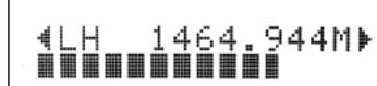
2 Channel and frequency are shown in the upper line of the VFD. The "bars" at the lower line of the VFD indicate the signal strength level of the current channel. To improve the reception of the selected channel, adjust or reposition the DAB antenna until the best reception is indicated.
3 To select other channels, toggle [TUNE ] to step through the channel list. Release [TUNE ] when you have arrived at your desired channel.
4 Press [ENTER] to tune the selected channel.
NOTE
The number of ensembles and stations that could be scanned will vary depending on your location.
PRUNE LIST
There maybe situations wherein certain stations become inactive. The "Prune List" option enables the deletion of these inactive stations in the service list.
1 While listening to a DAB broadcast, press front panel's [TUNER MODE] button and then [TUNE ] to select "Prune List".
2 Press [ENTER]. Any inactive stations are automatically deleted.
RESET
The "Reset" option allows the connected (and separately sold) NAD DAB Adaptor DB1 to be reset to its factory default settings.
1 While listening to a DAB broadcast, press front panel's [TUNER MODE] button and then [TUNE ] to select "Reset".
2 Press [ENTER]. "Reset? No" will be shown in the lower line of the VFD. Press [TUNE / ] to switch to "Reset? Yes" option.

3 To select "Reset? No" or "Reset? Yes", press [ENTER] while at the desired option. Selecting "Reset? Yes" will cause the DB1 to be reset to its factory default settings - the VFD will correspondingly show "No Service List".
LISTENING TO DAB RADIO
INFORMATION SETTINGS
While listening to a DAB broadcast, the type of information displayed in the lower line of the VFD can be varied. Toggle front panel's [INFO] button to step through the following display options:
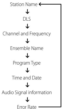
STATION NAME
The name or identification of the DAB broadcast station is shown. This is the default display.
DLS
Dynamic Label Segment (DLS) is the scrolling text supplied by the broadcasting station. It may contain information on music titles or details regarding the program or station.
CHANNEL AND FREQUENCY
The channel and frequency of the currently tuned DAB broadcast are displayed.
ENSEMBLE NAME
The name of the ensemble that is broadcasting the program is displayed.
PROGRAM TYPE
This is a description of the type of broadcast supplied by the station, such as Pop, Rock, Drama and the likes.
TIME AND DATE
The current time and date as supplied by the DAB station are displayed.
AUDIO SIGNAL INFORMATION
Displays the bit rate and audio type (stereo, mono or joint stereo) as transmitted by the DAB broadcast provider. These are set by the broadcaster to suit the type and quality of material being transmitted.
ERROR RATE
This displays the digital error rate (0 to 99) of the currently tuned channel - the lower the figure, the better the quality of the received broadcast.
The C 725BEE is equipped with a data port in the rear panel where an optional "NAD IPD 1 Dock with iPod" (NAD IPD 1) can be plugged in. With the NAD IPD 1 linking the C 725BEE with your own iPod player, you can enjoy listening to your favorite tracks and playlists.
You can control your iPod player using its own click wheel or the assigned buttons in the SR 8. With the corresponding SR 8 remote control function keys, you can select the materials stored in your iPod for playback as well as access many of its functions. The optional NAD IPD 1 also charges your iPod player while it is connected to the C 725BEE.
NOTES
- NAD IPD 1 and iPod player are optional and not supplied with your C 725BEE.
- iPod player functions, features and playback capabilities accessible through C 725BEE may vary depending on your iPod player model. Check NAD IPD 1's specifications with regards to specific iPod models it supports.
- C 725BEE is compatible with NAD IPD 1 and later NAD IPD variants. Check with your dealer or NAD audio specialist for other versions of NAD IPD compatible with C 725BEE.
CONNECTING THE OPTIONAL "NAD IPD 1 DOCK WITH iPod" AND iPod PLAYER TO THE C 725BEE
Make sure that all the devices are unplugged before making the connections.
1 Connect the NAD IPD 1's "DATA PORT" plug into the C 725BEE's "MP DOCK" data port.
2 Connect also the NAD IPD 1's AUDIO OUT to the C 725BEE rear panel. MP input (the default iPod source allocation in the C 725BEE).
3 Dock your iPod player into the NAD IPD 1.
4 After linking together your iPod player, NAD IPD 1 and the C 725BEE, you can now plug them IN to their applicable power sources.
5 With your iPod player, NAD IPD 1 and C 725BEE all at power ON state, press [MP] button in the front panel or in SR 8 to select "iPod" source - "iPod Connected" will be displayed in the lower line of the VFD.
NOTE
When the iPod player is removed from NAD IPD 1, the "iPod Connected" display in the lower line of the VFD will be extinguished. Dock your iPod player into the NAD IPD 1 - "iPod Connected" will be displayed in the lower line of the VFD.
iPod MENU OPTIONS
Refer to your docked iPod player's own display screen to view and make full use of its navigation and control features. Use your docked iPod's own click wheel and controls or the applicable SR 8 buttons to select through the available options as displayed in your iPod player's display screen.
NOTE
When using the SR 8 to control the iPod functions, make sure that the DEVICE SELECTOR is set to "MP".
CONTROL FEATURES
Use the following SR 8 control buttons to command your docked iPod player. Refer to your docked iPod's own display screen when executing the following commands.
MENU
Press [MENU] to return to a previous option or menu selection.
[▲/▼] NAVIGATION BUTTONS
While at menu options or selection lists, toggle [ / ] to go up or down the options, lists or song titles. For quicker scrolling up or down the list, press and hold [ / ] .
ENTER
Press [ENTER] to select an option or start playback when applicable.
SCAN[44/1]
During playback or PAUSE mode, press and hold [▶/▶] for fast forward or backward scanning of the current song.
SKIP [▶▶]
Press [▶/▶] to skip forward to the next song or skip back to the previous song.
[II] PAUSE
Press [II] during playback to stop playback temporarily. Resume play by pressing [II] again or [] .
RPT (REPEAT)
Toggle to playback repeatedly a particular song or repeat all songs in a list.
RANDOM
Enable playback of songs or albums in random order.
DISP (DISPLAY)
If the iPod's display screen is dim, press [DISP] to turn ON the backlight and illuminate the display screen.
NOTE
For other navigation functions, please refer to your iPod player's owner's manual.
iPod is a trademark of Apple Inc., registered in the U.S. and other countries.
TROUBLESHOOTING
| CONDITION | POSSIBLE CAUSES | POSSIBLE SOLUTIONS |
| No power. | ·The power cord is disconnected. | ·Plug the power cord into the wall outlet securely. |
| No sound. | ·Power AC lead unplugged or power not switched ON. | ·Check AC lead. |
| ·Mute ON. | ·Switch OFF Mute. | |
| No sound one channel. | ·Balance control not centered. | ·Center Balance control. |
| ·Speaker not properly connected or damaged. | ·Check connections and speakers. | |
| ·Input lead disconnected or damaged. | ·Check leads and connections. | |
| Weak bass/diffused stereo image. | ·Speakers wired out of phase. | ·Check connections to all speakers in the system. |
| No sound from Subwoofer. | ·Subwoofer is off, not powered or improperly connected. | ·Power-up subwoofer, check Sub's AC outlet or check connections. |
| Noisy reception, hiss. | ·Weak signal. | ·Check station tuning. Adjust or replace antenna. |
| Display shows "no service list". | ·DAB antenna not connected properly. | ·Check the connection and position of the DAB antenna. |
| ·No DAB coverage in the area. | ·Call your local DAB broadcast providers for coverage information. | |
| Reception with whistling, buzzing noise. | ·Interference from other computers, games consoles. | ·Check station tuning. Switch off or move the source of electrical noise. |
| No RDS information. | ·Station signal too weak. | ·Check station tuning. Adjust or replace antenna. |
| ·Station not transmitting RDS data. | ·Tune to an RDS station that supports station-name (PS mode) and radio-text (RT mode). | |
| C 725BEE does not respond to remote control. | ·Batteries are flat or incorrectly inserted. | ·Check batteries. |
| ·IR transmitter window on remote or IR receiver window on C 725BEE is obstructed. | ·Check IR windows and ensure clear line-of-sight from remote to C 725BEE. | |
| ·C 725BEE front panel is in very bright sunlight or ambient light. | ·Reduce sunlight/room lighting. |
- Reset C 725BEE to its factory default settings using front panel buttons only (120V version only): Press and hold [SPEAKER A] button and then [TONE DEFEAT]. "AH Reset...complete." is shown in the VFD.
- Reset C 725BEE to its factory default settings using front panel buttons only (230V version only): Press and hold [SPEAKER B] button and then [TONE DEFEAT]. "C Reset...complete." is shown in the VFD.
- All stored presets and settings will be deleted upon restoring your C 725BEE to its factory default settings.
NOTES
PREAMPLIFIER SECTION
LINE LEVEL INPUTS (MP, CD, DISC, AUX, TAPE)
| Input impedance (R and C) | 22 kΩ + 100pF |
| Input sensitivity | 250 mV (ref. rated power) |
| Maximum input signal | 6V |
| Signal / Noise ratio A-weighted1 | 95 dB |
| Signal / noise ratio pre-amp out, A-weighted | 107 dB |
| Frequency response | <±0.3dB (20 Hz - 20 kHz, Tone defeat on) |
| <±0.3dB (20 Hz - 20 kHz, Tone defeat off) | |
| THD + Noise, SMPTE IM | < 0.01 % at 5 V out |
| LINE LEVEL OUTPUTS | |
| Output impedance, Pre-out | 80 Ω |
| Output impedance, Record Out | Z+ 1 kΩ |
| Maximum output level, Pre-out | 11 V |
| Maximum output level, Record Out | 11 V |
| TONE CONTROLS | |
| Treble | ±5 dB at 10 kHz |
| Bass | ±8 dB at 100 Hz |
| TRIGGER OUT | |
| Output resistance | 75 Ω |
| Output current | 150 mA |
| Output voltage | 12 ±1 V |
POWER AMPLIFER SECTION
| Continuous output power into 8 Ω2 | 2x50 W (17 dBW) |
| Rated distortion (THD 20 Hz - 20 kHz) | 0.02 % |
| Clipping power | 61 W (maximum continuous power per channel 4 Ω and 8 Ω) |
| IHF Dynamic headroom - 8 Ω | +3.1 dB |
| 4 Ω | +4.7 dB |
| IHF dynamic power, 8 Ω | 102 W(20.0 dBW) (maximum short term power per channel) |
| 4 Ω | 148 W(21.7 dBW) |
| 2 Ω | 205 W(23.1 dBW) |
| Damping factor (ref. 8 Ω, 1 kHz) | >110 |
| Input impedance (R & C) | 20 kΩ +1 nF |
| Input sensitivity (rated output into 8 Ω) | 730 mV |
| Voltage gain | 28.7 dB |
| Frequency response 20 Hz - 20 kHz | ±0.2 dB |
| Signal/noise ratio, A-weighted | 102 dB |
| THD + Noise3 | <0.02 % |
| SMPTE IM4 | <0.02 % |
| IHF IM5 | <0.01 % |
| Headphone output impedance | 220 Ω |
SPECIFICATIONS
TUNER SECTION
FM SECTION
Tuning Range 87.5 - 108.5 MHz (50 kHz steps)
Usable Sensitivity (98 MHz) 12 dBu
Signal/Noise Ratio (60 dBμ IHF-WTD Mono) 65 dB
(60 dBμ IHF-WTD Stereo) 60 dB
Frequency Response ±1.5 dB (20 Hz - 15 kHz, 60 dBμ)
Channel Separation (60 dBμ) 30 Hz 30 dB
1 kHz 35 dB
10kHz 30dB
Capture Ratio (40 dBμ) 3 dB
AM Suppression 50 dB
(60 dBμ, 100% Mod. FM, 30% Mod. AM)
Image Rejection (119.4 MHz) 70 dB
I.F. Rejection (10.7 MHz) 70 dB
Pilot Suppression (60 dBμ) 60 dB
Total Harmonic Distortion 6 Mono 0.5%
Stereo 0.8%
Auto Search 15 - 25 dBu
RDS Decode Sensitivity ≤ 30 dBu
AM SECTION
Tuning Range 530 kHz - 1710 kHz (10 kHz steps, 120V version)
531 kHz- 1602 kHz (9 kHz steps, 230 V version)
Usable Sensitivity 50 dBu (999/1000 kHz)
S/N Ratio 45 dB (5 mV in)
Total Harmonic Distortion 3% (5 mV in)
IF Rejection (450 kHz) 40 dB
Image Rejection (F + 2xIF) 28 dB
Selectivity 20 dB
Frequency response ±6 dB (100 - 2.3 kHz, 5 mV)
PHYSICAL SPECIFICATIONS
Unit Dimensions (W x H x D) 435 x 133 x 350 (Net
435 × 149 × 396 (Gross)
Net Weight 9.4 Kg
Shipping Weight 11.0 Kg
LEGEND:
1 From CD input to speakers output, volume setting for 500mV in, 8Ω 1 W out
2 Minimum power per channel, 20Hz - 20kHz both channels driven with no more than rated distortion.
3 Total harmonic distortion, 20Hz - 20kHz from 250mW to rated output
4 Intermodulation distortion, 60Hz + 7kHz 4:1, from 250~mW to rated output
5 CCIF IM distortion, 19.5kHz + 1kHz rated output
6 Total Harmonic Distortion, 60 dBμ, L = R 75 kHz for 120V version; 40 kHz Dev for 230V version
7 Gross dimensions include feet, volume knob and extended speaker terminals.
Specifications are subject to change without notice.
For updated documentation and features, please log onto www.NADelectronics.com for the latest information about C 725BEE.

www.NADelectronics.com
©2008 NAD ELECTRONICS INTERNATIONAL
A DIVISION OF LENBROOK INDUSTRIES LIMITED
- NOTE TO CATV SYSTEM INSTALLER
- WARNING
- CAUTION
- FCC WARNING
- CAUTION REGARDING PLACEMENT
- IMPORTANT INFORMATION FOR UK CUSTOMERS
- IMPORTANT
- IF IN DOUBT CONSULT A COMPETENT ELECTRICIAN.
- NOTES ON ENVIRONMENTAL PROTECTION
- INFORMATION ABOUT COLLECTION AND DISPOSAL OF WASTE BATTERIES (DIRECTIVE 2006/66/EC OF THE EUROPEAN PARLIAMENT AND THE COUNCIL OF EUROPEAN UNION) (FOR EUROPEAN CUSTOMERS ONLY)
- NOTE: THE C 725BEE IS NOT AN AUTO VOLTAGE RECEIVER. CONNECT ONLY TO THE PRESCRIBED AC OUTLET, I.E., 120V 60HZ OR 230V 50HZ.
- RECORD YOUR MODEL NUMBER (NOW,WHILE YOU CAN SEE IT)
- INTRODUCTION
- IDENTIFICATION OF CONTROLS
- OPERATION
- THANK YOU FOR CHOOSING NAD.
- REFERENCE
- http://NADelectronics.com/warranty
- GETTING STARTED
- UNPACKING AND SETUP
- WHAT'S IN THE BOX
- SAVE THE PACKAGING
- CHOOSING A LOCATION
- NOTES ON INSTALLATION
- DO NOT REMOVE THE COVER; THERE ARE NO USER-SERVICEABLE PARTS INSIDE.
- ABOUT THE C 725BEE
- FRONT PANEL
- ABOUT ZONE FEATURE
- NOTE
- ATTENTION!
- REAR PANEL
- USING THE SR 8 REMOTE CONTROL
- SLEEP MODE
- REMOTE CONTROL
- USING THE ZR 5 REMOTE CONTROL
- LISTENING TO AM/FM RADIO
- ABOUT ANTENNAS
- ASSEMBLING THE LOOP ANTENNA
- SELECTING BAND
- IMPORTANT NOTICE
- TUNING STATIONS
- DIRECT TUNING
- SETTING RADIO PRESETS (AM/FM/DAB)
- RECALLING PRESETS
- DIRECT RECALL OF A PRESET
- DELETE A PRESET
- CHOOSING TUNER MODE
- ABOUT USER NAMES
- ENTERING USER NAMES
- ABOUTRDS
- VIEW RDS TEXT
- LISTENING TO DAB RADIO
- ABOUT DAB RADIO (230V VERSION ONLY)
- CONNECTING THE DAB MODULE
- NOTES
- DAB OPERATION
- SERVICE LIST
- DAB TUNER MODE
- STATION ORDER
- ALPHANUMERIC
- ENSEMBLE
- ACTIVE
- DRC
- MANUAL SCAN
- PRUNE LIST
- RESET
- INFORMATION SETTINGS
- STATION NAME
- DLS
- CHANNEL AND FREQUENCY
- ENSEMBLE NAME
- PROGRAM TYPE
- TIME AND DATE
- AUDIO SIGNAL INFORMATION
- ERROR RATE
- CONNECTING THE OPTIONAL "NAD IPD 1 DOCK WITH iPod" AND iPod PLAYER TO THE C 725BEE
- iPod MENU OPTIONS
- CONTROL FEATURES
- MENU
- [▲/▼] NAVIGATION BUTTONS
- ENTER
- SCAN[44/1]
- SKIP [▶▶]
- [II] PAUSE
- RPT (REPEAT)
- RANDOM
- DISP (DISPLAY)
- TROUBLESHOOTING
- PREAMPLIFIER SECTION
- LINE LEVEL INPUTS (MP, CD, DISC, AUX, TAPE)
- POWER AMPLIFER SECTION
- SPECIFICATIONS
- TUNER SECTION
- FM SECTION
- AM SECTION
- PHYSICAL SPECIFICATIONS
- LEGEND:
Brand : NAD
Model : C 725BEE
Category : Audio Amplifier