
CI9120 - Audio Amplifier NAD - Free user manual and instructions
Find the device manual for free CI9120 NAD in PDF.
| Product Type | Multichannel Audio Amplifier |
| Brand | NAD |
| Model | CI9120 |
| Output Power (Average Continuous) | 85 W (6 ohms), 86 W (4 ohms) |
| Total Harmonic Distortion + Noise | <0.03% (1 W to 80 W, 6 ohms) |
| Frequency Response | 10 Hz - 20 kHz (+0.5, -1.0 dB) |
| Power Bandwidth (-3 dB) | 5 Hz - 45 kHz |
| Gain | 28 dB |
| Input Impedance | 25 kOhms |
| Input Sensitivity | 1 V RMS (80 W into 6 ohms) |
| Damping Factor | >31 (20 Hz - 20 kHz) |
| Power Supply | 120 VAC, 50-60 Hz (240 V available) |
| Idle Power Consumption | 84/168 VA |
| Maximum Power Consumption | 960/1920 VA |
| Dimensions (W × H × D) | 437 × 133 × 451 mm (chassis) |
| Net Weight | 35-37 kg |
| Package Weight | 44 kg |
| Operating Temperature | 20°C above ambient, max 40°C |
| Ventilation Airflow | 4.25 m³/min maximum |
| Special Features | ATO Logic, OMC, Protection, Flex-Pad, 12V Trigger, SLEEP/WAKE Detection |
| Speaker Terminals | High current, accept bare wire, spade connectors, pin connectors |
| Mains Fuse | MDA-20/250V (model 9120 AH) - see replacement chart |
| Protections | Overheating, short circuit, overload (OMC and protection circuits) |
Frequently Asked Questions - CI9120 NAD
User questions about CI9120 NAD
0 question about this device. Answer the ones you know or ask your own.
Ask a new question about this device
Download the instructions for your Audio Amplifier in PDF format for free! Find your manual CI9120 - NAD and take your electronic device back in hand. On this page are published all the documents necessary for the use of your device. CI9120 by NAD.
USER MANUAL CI9120 NAD
Note to Installation personnel 3
Safety Instructions 4
II Operation 6-10
NAD ATO Logic 6
NAD OMC 7
NAD Protection Circuitry 7
Rear panel connections 8
Front panel connections 10
III Installation 11-16
Rack Mount 11
Shelf Mount. 11
Speaker Hook-up 12
Client Configuration (Flex-Pad) 14
Client Configuration (input/channel destination) 15
IV Troubleshooting 17
V Specifications 18
VI Fuse Replacement Chart 19
ATTENTION: INSTALLATION PERSONNEL
The mounting hardware was specifically engineered for the NAD CI-series amplifier. We recommend that you do not substitute the mounting hardware.
Due to the high-power capability of the NAD CI-series amplifier, the power supplies are heavy and may require more than one installation person to rack-mount the amplifier.
NOTE
The amplifier's weight must always rest on its bottom feet when placed on to a surface. Never put the amplifier down on its rear panel, with its front panel facing up. Doing so risks damage to the input/output connectors.
The amplifier generates a moderate amount of heat, requiring internal ventilation. Do not permit the air inlet and outlet grilles on the top, bottom, side, and back cover to be obstructed by papers or other materials.
NOTE
To prevent a fire or shock hazard, do not permit liquid or moisture to enter the amplifier. If liquid is accidentally spilled on it, immediately shut off the power and unplug the AC Mains cable from the wall outlet.
Do not open the amplifier or attempt to modify or repair it yourself. Refer all servicing to a qualified technician.
Specifications or design subject to change without notice.
All specifications are those in effect at time of printing.
NAD®, OMC™, ATO Logic™, and Flex-Pad™ are trademarks of NAD Electronics International, a division of Lenbrook Industries Limited.
©2000 NAD Electronics International, a division of Lenbrook Industries Limited

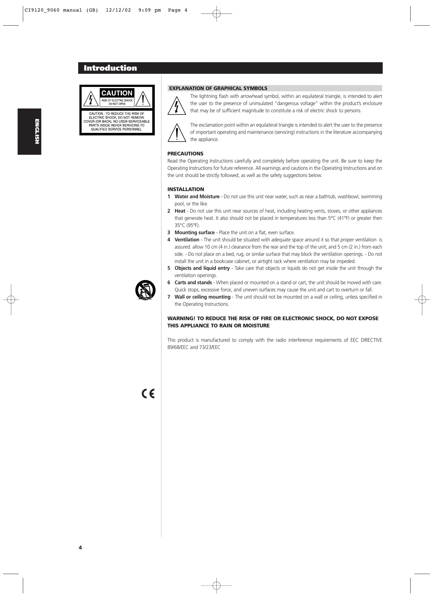
EXPLANATION OF GRAPHICAL SYMBOLS

The lightning flash with arrowhead symbol, within an equilateral triangle, is intended to alert the user to the presence of uninsulated "dangerous voltage" within the product's enclosure that may be of sufficient magnitude to constitute a risk of electric shock to persons.

The exclamation point within an equilateral triangle is intended to alert the user to the presence of important operating and maintenance (servicing) instructions in the literature accompanying the appliance.
PRECAUTIONS
Read the Operating Instructions carefully and completely before operating the unit. Be sure to keep the Operating Instructions for future reference. All warnings and cautions in the Operating Instructions and on the unit should be strictly followed, as well as the safety suggestions below.
INSTALLATION
1 Water and Moisture - Do not use this unit near water, such as near a bathtub, washbowl, swimming pool, or the like.
2 Heat - Do not use this unit near sources of heat, including heating vents, stoves, or other appliances that generate heat. It also should not be placed in temperatures less than 5^ (41°F) or greater then 35^ (95°F).
3 Mounting surface - Place the unit on a flat, even surface.
4 Ventilation - The unit should be situated with adequate space around it so that proper ventilation is assured. allow 10cm (4 in.) clearance from the rear and the top of the unit, and 5cm (2 in.) from each side. - Do not place on a bed, rug, or similar surface that may block the ventilation openings. - Do not install the unit in a bookcase cabinet, or airtight rack where ventilation may be impeded.
5 Objects and liquid entry - Take care that objects or liquids do not get inside the unit through the ventilation openings.
6 Carts and stands - When placed or mounted on a stand or cart, the unit should be moved with care. Quick stops, excessive force, and uneven surfaces may cause the unit and cart to overturn or fall.
7 Wall or ceiling mounting - The unit should not be mounted on a wall or ceiling, unless specified in the Operating Instructions.
WARNING! TO REDUCE THE RISK OF FIRE OR ELECTRONIC SHOCK, DO NOT EXPOSE THIS APPLIANCE TO RAIN OR MOISTURE
This product is manufactured to comply with the radio interference requirements of EEC DIRECTIVE 89/68/EEC and 73/23/EEC
ELECTRIC POWER
1 Power Sources - Connect this unit only to power sources specified in the Operating Instructions, and as marked on the unit.
2 Polarization - As a safety feature, some units are equipped with polarized AC power plugs which can only be inserted one way into a power outlet. If it is difficult or impossible to insert the AC power plug into an outlet, turn the plug over and try again. If it still does not easily insert into the outlet, please call a qualified service technician to service or replace the outlet. To avoid defeating the safety feature of the polarized plug, do not force it into a power outlet.
3 AC power cord - When disconnecting the AC power cord, pull it out by the AC power plug. Do not pull the cord itself.
- Never handle the AC power plug with wet hands, as this could result in fire or shock.
- Power cords should be routed to avoid being severely bent, pinched, or walked upon. Pay particular attention to the cord from the unit to the power socket.
- Avoid overloading AC outlets and extension cords beyond their capacity, as this could result in fire or shock.
4 Extension cord - To help prevent electric shock, do not use a polarized AC power plug with an extension cord, receptacle, or other outlet unless the polarized plug can be completely inserted to prevent exposure of the blades of the plug.
5 When not in use - Unplug the AC power cord from the AC outlet if the unit will not be used for several months or more. When the cord is plugged in, a small amount of current continues to flow to the unit, even when the power is turned off.
CAUTION
Modifications or adjustments to this product, which are not expressly approved by the manufacturer, may void the user's right or authority to operate this product.
DAMAGE REQUIRING SERVICE
Have the unit serviced by a qualified service technician if
The AC power plug has been damaged.
- Foreign objects or liquid have gotten inside the unit.
- The unit has been exposed to rain or water - The unit does not seem to operate normally.
- The unit exhibits a marked change in performance.
- The unit has been dropped, or the cabinet has been damaged
DO NOT ATTEMPT TO SERVICE THE UNIT YOURSELF
OWNER'S RECORD
For your convenience, record the model number and serial number (you will find them on the rear of your set) in the space provided below. Please refer to them when you contact your dealer in case of difficulty.
Model No.:
Serial No.:
NAD ATO LOGIC
The CI-series amplifier may be turned on in any one of three discrete ways for complete system flexibility: From the front-panel switch, the 12V-TRIGGER circuit, or by a "SLEEP/WAKE" signal-sensing circuit. The ON/OFF power control is managed by the Automated Turn-On logic or ATO Logic circuit that requires the amplifier to be switched back to standby in the same manner by which it was activated. In other words, if the amplifier is switched on via a 12V-control signal, it cannot be switched to standby via the front-panel switch, it must wait for removal of the 12V-control signal. In practice, you probably would use only one of the methods once the NAD CI-series amplifier is installed.
ATO LOGIC CHART
| SWITCH | Amber LED over front power switch | Green SWITCH LED | Green 12V-TRIGGER LED | Green SENSE LED |
| VACATION switch set to VACATION | OFF | OFF | OFF | OFF |
| VACATION switch set to ON | ON | OFF | OFF | OFF |
| Press front power switch with VACATION switch set to ON | OFF | ON | OFF | OFF |
| Press front power switch with VACATION switch set to ON | ON | OFF | OFF | OFF |
| 12V TRIGGER | Amber LED over front power switch | Green SWITCH LED | Green 12V-TRIGGER LED | Green SENSE LED |
| VACATION switch set to VACATION | OFF | OFF | OFF | OFF |
| VACATION switch set to ON | ON | OFF | OFF | OFF |
| 12 V INPUT TRIGGER = 0V with VACATION switch set to ON | ON | OFF | OFF | OFF |
| 12V INPUT TRIGGER = 12V with VACATION switch set to ON | OFF | OFF | ON | OFF |
| SLEEP/WAKE | Amber LED over front power switch | Green SWITCH LED | Green 12V-TRIGGER LED | Green SENSE LED |
| VACATION switch set to VACATION | OFF | OFF | OFF | OFF |
| VACATION switch set to ON | ON | OFF | OFF | OFF |
| SLEEP/WAKE SENSE DEFECT switch set to SENSE DEFECT with VACATION switch set to ON | ON | OFF | OFF | OFF |
| SLEEP/WAKE SENSE DEFECT switch set to SLEEP/WAKE and any source input greater than 20mV with VACATION switch set to ON | OFF | OFF | OFF | ON |
NAD OMC
NAD's proprietary Output Management Circuit (OMC) ensures that the full power is available at any reasonable load impedance. The OMC controls individual amplifier channels by managing the input level, in case of deliberately excessive input signal, and/or output level, in case of speaker or speaker cable fault. This not only protects the amplifier, but it also prevents loads attached to the amplifier from heating up excessively, an important factor when the reliability of an installed system is a consideration. When the OMC detects a potential fault situation and begins to limit current flow, an amber-coloured LED illuminates on the front panel to alert the installer/owner of a problem in the system. When the OMC is activated, the amplifier will continue to play without distortion, but the power level will be reduced to the amplifier channel that has the problem. If the fault condition persists and the impedance becomes too low the affected channels will initiate the NAD Protection Circuitry (see NAD Protection Circuitry below).
NAD PROTECTION CIRCUITRY
Every design decision, both electronic and mechanical, was made with absolute reliability of the amplifier as the primary goal. An auto-resetting protection circuit is also part of the CI-series amplifiers' design. The fast acting protection circuit jumps into action if the amplifier overheats or encounters a short circuit condition. A red front-panel LED indicates that the Protection circuit has been activated. Only the amplifiers being affected by a short circuit condition will be in the protection mode; all other channels will continue to play normally. When the condition is normalized the affected channels reset. In the unlikely event of amplifier failure, the CI-series amplifier is designed to be easily field serviceable with all amplifying circuitry mounted on plug-in modules.
REAR-PANEL CONTROLS AND CONNECTIONS
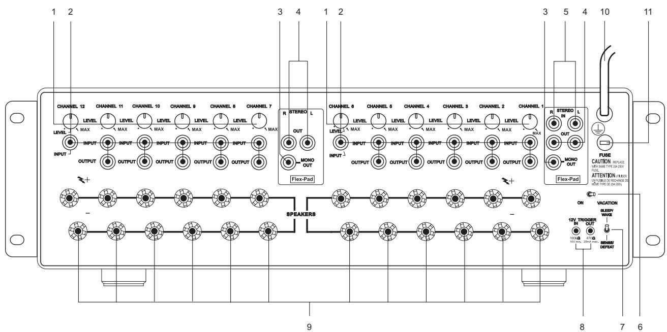
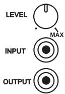
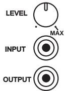
1 There is one CHANNEL trimmer per amplifier channel. Each trimmer will attenuate each input from a minimum to MAX setting (approx - 13 dB to 0.0 dB). We have designed the adjustment range sufficient to match the speaker sensitivity both from room-to-room and per speaker for multi-speaker installations. The design of this trimmer is for sensitivity matching only, not a volume control. It is highly unlikely one would adjust the trimmers once the installation was complete, thus for this reason we have placed the trimmers at the back of the amplifier.
2 Each amplifier CHANNEL INPUT OUTPUT is a direct pass-through connection, thus the source impedance of each channel input is exactly the impedance of the output. The special design of the NAD RCA cables that accompany the NAD CI-series amplifier allows for up to 6 channels to be fed from one channel of the Flex-Pad STEREO and MONO OUT, without degradation in sound quality. For example, one can jumper from Flex-Pad OUT Right to CHANNEL 1 INPUT, then from CHANNEL 1 OUTPUT to CHANNEL 2 INPUT, from CHANNEL 2 OUTPUT to CHANNEL 3 INPUT, and so on up to 6 channels of inputs. The NAD CI-series RCA jumper cables are specially designed low-capacitance high-performance cables. We do not recommend that you use any other RCA jumper cables than the NAD RCA jumper cables supplied with the NAD CI-series amplifier, to do so may cause significant loss in music fidelity or possible other problems.
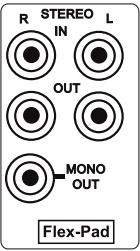
3 The Flex-Pad MONO OUT is a sum of the stereo right and left inputs with an output impedance of 75 ohms. We do not recommend driving more than 6 amplifier inputs with this MONO OUT source.
4 The Flex-Pad STEREO right and left OUT is a stereo buffer with an output impedance of 75 Ohms per output, capable of driving up to 6 NAD CI-series amplifier inputs per output. We do not recommend you drive more than 6 amplifier inputs per Flex-Pad output.
5 The Flex-Pad STEREO right and left IN is a high-impedance input specifically designed for connection to preamplifier or home-theatre processor outputs. We strongly recommend that these inputs not be connected to equipment that does not have a volume control!
6 The VACATION switch is the master on/off control for the amplifier. When the switch is in the on state the amplifier is in standby as shown by the amber LED above the power switch on the front panel. If the amplifier will not be used for an extended period of time, switch the VACATION switch to the VACATION position.
7 The SLEEP/WAKE, SENSE/DEFEAT switch logic controls the standby/on-state of the amplifier via the presences or absence of audio signal at the Flex-Pad or amplifier channel inputs. The SLEEP/WAKE, SENSE/DEFEAT switch must be in the SLEEP/WAKE position in order to use this logic. When the SLEEP/WAKE, SENSE/DEFEAT switch is in the SENSE/DEFEAT position, this logic control is deactivated.
When the switch is in the SLEEP/WAKE position, the NAD CI-series amplifier will instantaneously turn on from a standby state, sensing any input signal from any channel as seen by a lit green SENSE LED on the front panel of the amplifier (approximately above 20mV RMS input). If all of the audio signals are absent for approximately 5 minutes, the amplifier will switch automatically to standby condition, with the green SENSE LED off, and the amber LED over the front panel switch lit.
When the switch is in the SENSE/DEFEAT position, the amplifier will not turn on even if an input signal is present on any channel or Flex-Pad input.
8 The 12V TRIGGER IN and OUT connectors are 3.5mm monotype miniature phone jacks, with the centre pin of each serving respectively as a 12V signal sensor and 12V signal driver. We recommend that you use a good quality cable with shield when attaching the 3.5mm monotype plugs so as to prevent false triggering of the amplifier due to electro-magnetic interference from nearby electronic equipment. The 12V-IN TRIGGER allows you to have an external 12V signal turn on the NAD CI-series amplifier from standby. This 12V signal must be a continuous 12V signal in order to keep the amplifier in the on state. Once you remove the 12V signal the amplifier will return to standby. The 12V-OUT TRIGGER allows you to control other products with a 12V sensor, by the NAD CI-series amplifier. The 12V-OUT TRIGGER is constantly present when the NAD CI-series amplifier is in the on state, and absent when in standby or VACATION state.
NOTES
- Check the specifications of the trigger input terminal on the other components to ensure these are compatible with the NAD Cl-series amplifiers.
- All 12V-TRIGGER inputs and outputs on other NAD components with a 12V-TRIGGER feature are fully compatible with the NAD Cl-series amplifier's IN/OUT 12V-TRIGGER.
- Before making any connections to any 12V-TRIGGER input or output, make sure all components are disconnected from the AC mains.
- If in doubt over the connections, installation and/or operation of the IN/OUT 12V-TRIGGER connections consult your NAD dealer or sales representative.
- Failure to observe the above may result in damage to the NAD Cl-series amplifier and/or any ancillary components attached to it.
9 There is one set of speaker terminals per amplifier channel. They are marked "+" and "- to indicate their polarity.
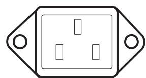
10 There are two discrete-types of AC-power cords. Refer to figures below for the type that relates to your NAD CI-series amplifier:
Before connecting the AC-power cord to a live wall socket insure that all inputs/outputs are connected first. Always disconnect the AC-power cord plug from the live wall socket first, before disconnecting any cable from the CI-series amplifier. If you must use an extension cord, select a heavy-duty cord of the type used for large electrical appliances, such as an air conditioner AC-extension cord (16 AWG). We strongly recommend that you not connect the amplifier's mains cable to the accessory AC outlets on a preamplifier. Such convenience outlets are not designed to supply the high-power levels that the NAD CI-series amplifier requires.
11 There is a fuse holder nearby or next to the AC-line cord. In the unlikely event a fuse may need to be replaced, unplug the line cord form the wall. Then remove all connections from the amplifier. Only replace the fuse with the same type, size, and specification. Refer to "SPECIFICATIONS, NAD Models CI 9060 and CI 9120" at the back of this instruction manual for the correct number, type and size of the replacement fuse.
CAUTION
Failure to replace the fuse with the correct number, brand name, and type listed in the "FUSE REPLACEMENT - PLEASE NOTE CAREFULLY" chart, found in the back of this instruction manual under section "Fuse Replacement Chart" will eventually lead to either another blown fuse or amplifier damage.
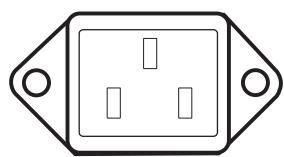

IEC AC POWER RECEPTACLE
CAPTIVE AC POWER CORD RECEPTACLE
FRONT-PANEL CONTROLS AND INDICATORS
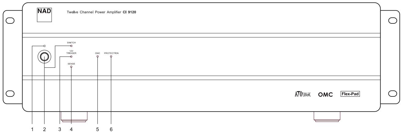
1 The amber standby indicator LED over the front power switch must be on for the amplifier's ATO Logic to function. This is achieved by having the "VACATION switch" in the ON position (refer to "Rear-Panel Controls and Connections": VACATION switch section).
2 The front-panel momentary-contact switch will power on, and place into standby, the NAD CI-series amplifier, denoted by the green LED labelled SWITCH. If you power on the amplifier via the front panel switch, the amber standby LED will turn off, and the SWITCH LED will turn green. Once you turn on the amplifier via the front-panel switch, only the front-panel switch can return the amplifier to standby state.
3 The 12V-TRIGGER LED illuminates green when the amplifier switches from standby to power on state via the 12V input (refer to "Rear-Panel Controls and Connections": 12V-TRIGGER INPUT section). Once you turn on the amplifier via the 12V-IN TRIGGER, only the absence of the 12V can return the amplifier to standby state.
4 The SENSE LED illuminates green when the amplifier senses a signal greater than 20mV RMS on any of the amplifier inputs refer to "Rear-Panel Controls and Connections": SLEEP/WAKE, SENSE/DEFEAT section). Once you turn on the amplifier via the SLEEP/WAKE sense logic, only the absence of a signal to all the amplifier's inputs can return the amplifier to standby state.
5 The OMC LED illuminates amber when the amplifier senses too much input signal or the load impedance drops below 2 to 3 Ohms, in either case a potential fault condition. When the fault condition is removed, the OMC LED will turn off, and the amplifier will return to normal operation.
6 The PROTECTION LED illuminates red when the amplifier protects itself. For example, in the unlikely event of overheating, protection would be active and the protection LED would light red. The amplifier will stay in this state until one removes the fault condition. Once you remove the fault condition, the amplifier will come out of the protection state, and the amplifier will return to normal operation.
RACK-MOUNT INSTALLATION
Instructions for installation of the NAD CI-series amplifier are supplied with the Rack-Mounting hardware. Supplied with these instructions are 8 pieces of plastic bushings and 4 #10-32 bolts. These bolts with specifically designed plastic bushings are engineered to prevent ground loops and will support the weight of the NAD CI-series amplifier (see Figure 1).
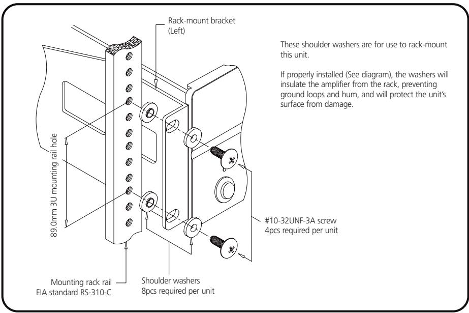
Figure 1
Since the NAD Cl-series amplifier is a heavy amplifier, we recommend that you mount the NAD Cl amplifier as close to the bottom of a rack as possible to promote a stable Rack-Mount installation.
The NAD CI-series amplifier takes up 3 standard, rack places on an EIA/IEC 19-inch rack. The NAD CI-series amplifier needs special consideration when rack-mounting to allow sufficient ventilation space all around the amplifier. Thus we recommend one should allow at least a one-rack-space below and above the amplifier as clearance, and that you allow more than 2 to 3 inches (5 to 7.5cm ) of space on all six sides of the NAD CI-series amplifier. Please refer to the "Ventilation Air Flow" specification found at the back of the instruction manual for maximum airflow requirements.
SHELF-MOUNT INSTALLATION
REMOVAL OF RACK-MOUNT BRACKETS
This unit may be installed on any level surface that is strong enough to support the amplifier's weight. Please refer to the "Specifications" section at the back of the instruction manual for the exact weight of your NAD CI-series amplifier. Since the NAD CI-series amplifier was shipped with Rack-Mounting hardware attached, below is the removal procedure of the rack-mounting shelf brackets. We strongly recommend that you follow these procedures in order to prevent damage to the NAD CI amplifier or personal injury:
To detach the rack-mount bracket, place the amplifier on a flat surface, remove each set of three fixing screws on each side. Once the screws are removed, slide the bracket toward the rear of the amplifier to release it from its fittings in the chassis bottom surface and then slide the bracket toward you.
For self-mount installations of the NAD CI-series amplifier, we recommend that you do not place equipment on top of the amplifier. Leave at least 2 to 3 inches (5 to 7.5cm ) on all sides of the amplifier so that the NAD CI-series amplifier achieves adequate airflow. We strongly recommend that you do not block the side, top, back and front, airflow vents. Since its power transformer generates a significant magnetic hum field, a turntable (especially one with a magnetic pick-up cartridge) or a television should not be located adjacent to, directly above, or below the amplifier.
SPEAKER HOOK-UP
This amplifier is equipped with special high-current, binding-post speaker terminals to handle the highest peak-power levels that may occur with low-impedance speakers. At moments when the amplifier is producing maximum power, voltages of nearly 100V may be present on the speaker terminals, so plastic covers protect the terminals. To connect loudspeaker cables, first switch off the amplifier's power by disconnecting the AC-power cord from the wall outlet.
Connect the wires from one of your speakers to the "+" and "-" terminals on the rear panel of the NAD Cl-series amplifier. In each channel, the red terminal is the positive "+" output, and the black terminal is the negative "-" or "ground" terminal (see Figure 2).
Use heavy-duty (16-gauge/2mm or thicker) wire, especially with 4-ohm loudspeakers. Bare wires can be connected directly to the binding-post terminals. For a longer lasting and more corrosion resistant connection, you may install speaker cables with gold-plated connectors (pin connectors or spade lugs), or you can install such connectors on the wires yourself. Connections to each binding post may be made in the three ways described below.
1 Pin connectors: A pin connector is a slim metal shaft that is crimped or soldered onto the end of a wire. The threaded shaft of each binding post contains an opening that accepts pin connectors up to 3mm in diameter. Unscrew the plastic bushing on each terminal to expose the hole in the metal shaft. Insert the pin connector through the hole, and turn the bushing clockwise until it is tight (see Figure 2).
2 Spade lugs: Unscrew the plastic bushing, insert the U-shaped spade lug into the oblong gap and tighten the bushing down on it (see Figure 2).
3 Bare wires: Separate the two conductors of the cord (if they are supplied as a pair), and strip off a half-inch (1cm) of insulation from each. In each conductor, twist together the exposed wire strands. Unscrew the plastic bushings for "+" and "-" insert the bare wire through the hole in the metal shaft, and tighten the plastic bushing until it grasps the wire securely (see Figure 2). Check to be sure that no loose strand of wire is touching the chassis or an adjacent terminal. Re-tighten the bushing after a week or so to make sure that any play that may have developed is eliminated.
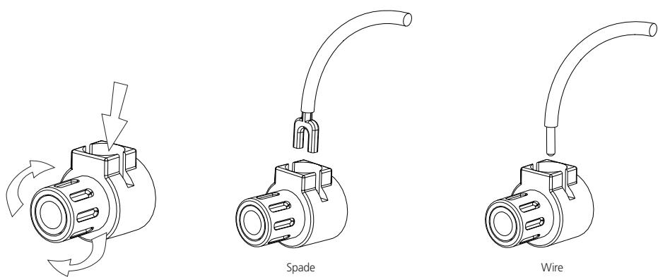
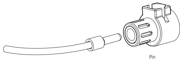
Figure 2
PHASING
Stereo speakers must operate "in phase" with each other to produce a focused stereo blend and to reinforce rather than cancel each other's output at low frequencies. An in-phase connection is assured if the red (positive) terminal on the amplifier is connected to the red (positive) terminal on the loudspeaker in each channel. If your speakers are easily moved, their phasing can easily be checked. Make the connections to both speakers, place the speakers face-to-face only a few inches apart, play some music, and listen. Then swap the connection of the two wires at the back of ONE of the speakers, and listen again. The connection that produces the fullest, most extended bass output is the correct one. Once you have determined the correct phasing, connect the wires securely to the speaker terminals, being careful not to leave any loose strands of wire that might touch the wrong terminal and create a partial short-circuit, then move the speakers to their intended locations.
If the speakers cannot easily be placed face-to-face, then phasing must rely on the "polarity" of the connecting wires. The speaker terminals on the amplifier are identified as red "+" and black "-" in each channel. The terminals at the rear of the speakers are also marked for polarity, either via red and black connectors or by labels: "+" , 1 , or "8 ohms" for positive , - , "0", or "G" for negative. The red "+" terminal on the amplifier should be connected to the red (positive) terminal of the speaker in each channel. To facilitate this, the two conductors comprising the speaker wire in each channel are different, either in the colour of the wire itself (copper vs. silver) or in the presence of a small ridge or rib-pattern on the insulation of one conductor. Use this pattern to establish consistent wiring to both speakers of a stereo pair. Thus if you connect the copper-coloured wire (or ribbed insulation) to the "+" amplifier terminal in the Left channel, do the same in the Right channel. At the other end of the wire, if you connect the coppercoloured wire (or the ribbed insulation) to the red (positive) terminal on the left channel speaker, do the same at the right channel speaker.
NOTE
Safety organizations recommend that the speaker terminals of a very powerful amplifier should be covered. Potentially dangerous voltages are present on these terminals when the amplifier is producing maximum power. For your protection and in order to comply with these regulations, we have chosen speaker terminals of the very highest quality for the NAD Cl-series amplifier. These terminals are covered by plastic bushings, which prevent the touching of metal parts.
12V TRIGGER
V

100kΩ
10V min.
470Q
25A max.


MONO
Flex-Pad
STEREO L
OUT


_MONO
out
Flex-Pad
ATTENTION INSTALLATION PERSONNEL
The following charts should be completely filled out and left in the possession of the NAD CI-series amplifier's owner, to be used for future referral. Record all speaker locations, zones, controls, sources, and individual amplifier level settings.
NAD MODEL NUMBER
NUMBER OF ZONES per AMPLIFIER
LOCATION of NAD CI-SERIES
AMPLIFIER
AMPLIFIER POWER CONTROL
SOURCE & DESCRIPTION OF POWER CONTROL
SOURCE FOR 12V-TRIGGER
EQUIPMENT FED BY NADCI
12V-TRIGGER
SOURCE FOR SIGNAL SENSE
CLIENT CONFIGURATION
FLEX-PAD FOR THE FIRST 6 CHANNELS
SOURCE L
SOURCE R
DESTINATION L
DESTINATION R
DESTINATION MONO
FLEX-PAD FOR THE SECOND 6 CHANNELS
DESTINATION L
DESTINATION R
DESTINATION MONO
CLIENT CONFIGURATION (INPUT/CHANNEL DESTINATION)
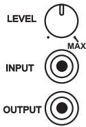
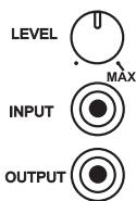
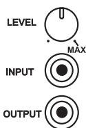
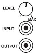
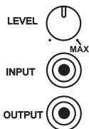
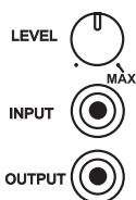
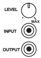
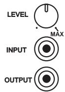
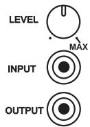
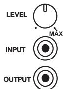
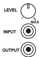
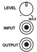
MARK OFF INDIVIDUAL AMPLIFIER LEVEL SETTING FOR EACH CHANNEL BELOW
CHANNEL 1
| SOURCE | |
| ROOM LOCATION | |
| SPEAKER DESCRIPTION |
CHANNEL 2
| SOURCE | |
| ROOM LOCATION | |
| SPEAKER DESCRIPTION |
CHANNEL 3
| SOURCE | |
| ROOM LOCATION | |
| SPEAKER DESCRIPTION |
CHANNEL 4
| SOURCE | |
| ROOM LOCATION | |
| SPEAKER DESCRIPTION |
CHANNEL 5
| SOURCE | |
| ROOM LOCATION | |
| SPEAKER DESCRIPTION |
CHANNEL 6
| SOURCE | |
| ROOM LOCATION | |
| SPEAKER DESCRIPTION |
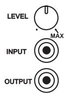
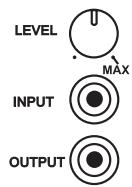
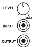
LEVEL

INPUT

OUTPUT

LEVEL

INPUT

OUTPUT

LEVEL

INPUT

OUTPUT

1

INPUT

OUTPUT

LEVEL

INPUT

OUTPUT

LEVEL

INPUT

OUTPUT


CLIENT CONFIGURATION (INPUT/CHANNEL DESTINATION CONTINUED)
MARK OFF INDIVIDUAL AMPLIFIER LEVEL SETTINGS FOR EACH CHANNEL BELOW:
CHANNEL 7
| SOURCE | |
| ROOM LOCATION | |
| SPEAKER DESCRIPTION |
CHANNEL 8
| SOURCE | |
| ROOM LOCATION | |
| SPEAKER DESCRIPTION |
CHANNEL 9
| SOURCE | |
| ROOM LOCATION | |
| SPEAKER DESCRIPTION |
CHANNEL 10
| SOURCE | |
| ROOM LOCATION | |
| SPEAKER DESCRIPTION |
CHANNEL 11
| SOURCE | |
| ROOM LOCATION | |
| SPEAKER DESCRIPTION |
CHANNEL 12
| SOURCE | |
| ROOM LOCATION | |
| SPEAKER DESCRIPTION |
| PROBLEM | CAUSE | SOLUTION |
| No sound | • Power AC-mains cable unplugged | • Check if AC-mains cable is plugged in and power switched on |
| • VACATION switch set to VACATION | • Set the VACATION switch to ON | |
| • The Protection mode is engaged | • Switch amplifier off via VACATION switch. Make sure ventilation slots on top, side, and back of the amplifier are not blocked. After amplifier has cooled down, switch the amplifier on | |
| • External fuse blown | • Replace fuse | |
| • Consult dealer/installer | ||
| No sound in one channel | • Speaker not properly connected or damaged | • Check all connections both at the speakers and at the amplifier |
| • Input cable pulled loose or making poor contact at Flex-Pad socket | • Check leads and Flex-Pad cables | |
| • Short-circuit or broken wire in a defective patch or speaker cable | • Switch the amplifier to VACATION mode, check and replace cables if necessary | |
| Weak bass/ poor stereo image | • Speakers wired out-of-phase | • Reverse connections at the back of the suspect amplifier output |
| • Check connections to all speakers in the affected zone/room | ||
| Low or distorted sound in one zone/room and OMC LED on | • Shorted speaker cable to zone/room | • Switch off amplifier via VACATION switch and remove one at a time a pair of speaker cables from the amplifier, then switch the VACATION switch to the ON position and restore audio source. Continue this procedure until the OMC LED does not turn on. Replace the shorted speaker cable to the zone/room |
| • Too high of an input level to one or more amplifier channels | • Turn down the input level to the room/zone that may be suspect | |
| • Too low an impedance on one or more amplifier zones/rooms | • Too many speakers connected to one channel, or incorrect speaker pad or matching transformer impedance settings. Remove some speakers or check speaker pad and/or documentation supplied from the speaker pad manufacturer for correct impedance settings | |
| • Damage to speaker pad. Replace speaker pad |
Power Rating
85 Watts continuous average power into 6 Ohms at any frequency between 20Hz and 20kHz with all channels driven at less than 0.03% THD.
86 Watts continuous average power into 4 Ohms at any frequency between 20Hz and 20kHz with all channels driven at less than 0.03% THD.
IM Distortion (SMPTE)
80 Watts into 6 Ohms < 0.03 %
80 Watts into 4 Ohms < 0.03 %
IM Distortion (CCIF, Any Combination from 1kHz to 20kHz)
80 Watts into 6 Ohms < 0.03 %
80 Watts into 4 Ohms < 0.03
THD + Noise at 1 Watt into 6 Ohms
20Hz 0.03%
1kHz 0.03%
10kHz 0.03%
20kHz 0.03%
THD + Noise at 80 Watts into 6 Ohms
20Hz 0.03%
1kHz 0.03%
10kHz 0.03%
20kHz 0.03%
Frequency Response @ 1 Watt into 6 Ohms
10Hz to 20kHz + 0.5, -1.0dB
Power Bandwidth (-3dB)
5Hz to 45kHz
Gain
28dB
Amplifier Trimmer Adjustment Range
14 ± 2 dB
Damping Factor
30
Dynamic Headroom into 6 Ohms
1.6dB
OMC Activation
< 3 Ohms across any speaker terminal
ATO Logic
SENSE Input Sensitivity
12V Trigger Input Voltage Range
12V Trigger Output Current
20mV rms
10.0V to 20.0V DC, 100k Ohms
25 ± 5 ~mA, 470 Ohms
25k Ohms
Input Impedance
Input Sensitivity
80 Watt into 6 Ohms
1V rms
1 Watt into 6 Ohms
114mV rms
Damping Factor 20Hz to 20kHz
<31
Rise Time
5kHz, 50V peak-to-peak square wave,
20% to 80%
4 μs
Power Consumption (Continuous, All Channels Driven)
Quiescent 84/168VA
Maximum 960/1920VA
80 Watts into 6 Ohms
744/1488VA
80 Watts into 4 Ohms
900/1800VA
GENERAL
Power (available in 240V)
Ambient Operating Temperature
Operating Temperature
Ventilation Air Flow
Net Chassis Dimensions
120VAC/50-60Hz
< 100°F (40°C)
68^ F (20°C)
above ambient temperature
150 cubic feet/minute maximum
17.2x5.3x17.8 inches (437x133x451 mm)
or 3 rack heights
18.9x19.0x5.7 inches (480.1x481.7x144.8 mm)
(includes rack mounting hardware,
feet and speaker terminals)
55-60 lb (25-27 Kg), 75 lb (34 Kg)
78-82 (35-37 Kg), 97 lb (44 Kg)
Maximum Gross Dimensions
Weight CI 9060, Packed
Weight CI 9120, Packed
FUSE REPLACEMENT - PLEASE NOTE CAREFULLY
The fuses listed in the chart below have been carefully selected and thoroughly tested to deliver optimal performance and still accomplish their protective functions. Replace the AC INPUT LINE FUSE only with one of the fuses listed in the chart. DO NOT USE ANY SUBSTITUTE FUSES OF DIFFERENT TYPES OR WITH DIFFERENT CURRENT RATINGS, TIME-CURRENT CURVES OR VALUES. Failure to observe this precaution may cause damage to the amplifier circuits, MAY CREATE A FIRE HAZARD AND/OR DEFEAT THE SAFETIES BUILT INTO THE AMPLIFIER, AND MAY VOID THE WARRANTY.
Model
9120 AH
9060 AH
9120 C (1 & 2)
9060 C (1 & 2)
Bussman
MDA-20/250V
MDA-12/250V
MDA-10/250V
MDA-6/250V
Littelfuse
3AB 326020/250V
3AB 326012/250V
3AB 326010/250V
3AB 326060/250V
Bel
N/A 12/250
GSA 10/250
GSA 6/250
TABLE DES MATIÈRES
III Installation 11-16
©2000, NAD Electronics International, division de Lenbrook Industries Limited

EXPLICATION DES SYMBOLES GRAPHIQUES

CONFIGURATION CLIENT (FLEX-PAD)
FLEX-PAD POUR LES SIX PREMIÈRES VOIES
SOURCE G (L)
SOURCE D (R)
DESTINATION L (G)
DESTINATION D (R)
DESTINATION MONO
FLEX-PAD POUR LES SIX VOIES SUIVANTES
DESTINATION L (G)
DESTINATION D (R)
DESTINATION MONO
CONFIGURATION CLIENT (ENTRÉE / VOIE UTILISÉE) - SUITE
REPÉRÉZ LE RÉGLAGE INDIVIDUEL DE LA COMMANDE DE NÈVEAU DE CHAQUE VOIE DE L'AMPLIFICATEUR SUR LES SCHEMAS CI-DESSOUS
VOIE 1
| SOURCE | |
| PIÈCE | |
| DESCRIPTION DU HAUT-PARLEUR |
VOIE 2
| SOURCE | |
| PIÈCE | |
| DESCRIPTION DU HAUT-PARLEUR |
VOIE 3
| SOURCE | |
| PIÈCE | |
| DESCRIPTION DU HAUT-PARLEUR |
VOIE 4
| SOURCE | |
| PIÈCE | |
| DESCRIPTION DU HAUT-PARLEUR |
VOIE 5
| SOURCE | |
| PIÈCE | |
| DESCRIPTION DU HAUT-PARLEUR |
VOIE 6
| SOURCE | |
| PIÈCE | |
| DESCRIPTION DU HAUT-PARLEUR |


CONFIGURATION CLIENT (ENTRÉ / VOIE UTILISÉE) - SUITE
REPÉREZ LE RÉGLAGE INDIVIDUEL DE LA COMMANDE DE NÈVEAU DE CHAQUE VOIE DE L'AMPLIFICATEUR SUR LES SCHEMAS CI-DESSOUS
VOIE 7
| SOURCE | |
| PIÈCE | |
| DESCRIPTION DU HAUT-PARLEUR |
VOIE 8
| SOURCE | |
| PIÈCE | |
| DESCRIPTION DU HAUT-PARLEUR |
VOIE 9
| SOURCE | |
| PIÈCE | |
| DESCRIPTION DU HAUT-PARLEUR |
VOIE 10
| SOURCE | |
| PIECE | |
| DESCRIPTION DU HAUT-PARLEUR |
VOIE 11
| SOURCE | |
| PIÈCE | |
| DESCRIPTION DU HAUT-PARLEUR |
VOIE 12
| SOURCE | |
| PIÈCE | |
| DESCRIPTION DU HAUT-PARLEUR |
Distorsion IM (SMPTE)
SYSTEMKCONFIGURATION (FLEX-PAD)
FLEX-PAD FÜR DIE ERSTEN 6 KANÄLE
QUELLE L
QUELLE R
ZIEL L
ZIEL R
ZIEL MONO
10 Hz a 20 kHz +0.5, -1.0 dB
80 Watt in 6 Ohm 744/1488 VA
80 Watt in 4 Ohm £ 900/1800 VA
GENERALITA
IEC AC POWER RECEPTACLE

CAPTIVE AC POWER CORD RECEPTACLE
(Classificada volta organismo Society of Motion Pictures and Television Engineers)
10.0 V a 20.0 V DC, 100 K Ohms
INSTALLATION PÅ HYLLA
HUR DU TAR BORT RACKMONTERINGSVINKLARNA
INKOPPLING AV HÖGTALARE
KONFIGURATION (FLEX-PAD)
FLEX-PAD FÖR DE FÖRSTA 6 KANALERNA
SIGNALKÄLLA L
SIGNALKÄLLA R
DESTINATION L
DESTINATION R
DESTINATION MONO
FLEX-PAD FÖR DE SISTA 6 KANALERNA
DESTINATION L
DESTINATION R
DESTINATION MONO
KONFIGURATION (INGÄNGAR/KANALDESTINATION)
MARKERA FÖRSTÄRKARNIVÄERNA FÖR VARJE KANAL NEDAN:
KANAL 1
| SIGNALKÄLLA | |
| PLACERAD I RUM | |
| HÖGTALARBESKRIVNING |
KANAL 2
| SIGNALKÄLLA | |
| PLACERAD I RUM | |
| HÖGTALARBESKRIVNING |
KANAL 3
| SIGNALKÄLLA | |
| PLACERAD I RUM | |
| HÖGTALARBESKRIVNING |
KANAL 4
| SIGNALKÄLLA | |
| PLACERAD I RUM | |
| HÖGTALARBESKRIVNING |
KANAL 5
| SIGNALKÄLLA | |
| PLACERAD I RUM | |
| HÖGTALARBESKRIVNING |
KANAL 6
| SIGNALKÄLLA | |
| PLACERAD I RUM | |
| HÖGTALARBESKRIVNING |


KONFIGURATION (INGÄNGS/KANAL DESTINATION FORTSÄTTNING)
MARKERA FÖRSTÄRKARNIVÄERNA FÖR VARJE KANAL NEDAN
KANAL 7
| SIGNALKÄLLA | |
| PLACERAD I RUM | |
| HÖGTALARBESKRIVNING |
KANAL 8
| SIGNALKÄLLA | |
| PLACERAD I RUM | |
| HÖGTALARBESKRIVNING |
KANAL 9
| SIGNALKÄLLA | |
| PLACERAD I RUM | |
| HÖGTALARBESKRIVNING |
KANAL 10
| SIGNALKÄLLA | |
| PLACERAD I RUM | |
| HÖGTALARBESKRIVNING |
KANAL 11
| SIGNALKÄLLA | |
| PLACERAD I RUM | |
| HÖGTALARBESKRIVNING |
KANAL 12
| SIGNALKÄLLA | |
| PLACERAD I RUM | |
| HÖGTALARBESKRIVNING |
IM Distortion (SMPTE)
5kHz, 50V peak-to-peak square wave,
20% to 80%
4 us
Effektforbrukning (kontinuierlg, Alla k
Tomgang 84/168 VA
Maximum 960/1920 VA
80 Watt vid 6 Ohm
744/1488 VA
80 Watt vid 4 Ohm
900/1800 VA
GENERELLT
Natspanning
240VAC/50-60Hz
m = 311 ;
m = 311 ;
100kΩ
10V min.
4700
25mA max.
STEREO L
OUT
T
1
/
(1)
MONO
OUT
Flex-Pad
INSTALLATIEPERSONEEL - LET OP
(incl. rack-bevestigingshardware,
www.NADelectronics.com
©2002 NAD ELECTRONICS INTERNATIONAL A DIVISION OF LENBROOK INDUSTRIES LIMITED
- ATTENTION: INSTALLATION PERSONNEL
- NOTE
- EXPLANATION OF GRAPHICAL SYMBOLS
- PRECAUTIONS
- INSTALLATION
- WARNING! TO REDUCE THE RISK OF FIRE OR ELECTRONIC SHOCK, DO NOT EXPOSE THIS APPLIANCE TO RAIN OR MOISTURE
- ELECTRIC POWER
- CAUTION
- DAMAGE REQUIRING SERVICE
- DO NOT ATTEMPT TO SERVICE THE UNIT YOURSELF
- OWNER'S RECORD
- NAD ATO LOGIC
- NAD OMC
- NAD PROTECTION CIRCUITRY
- REAR-PANEL CONTROLS AND CONNECTIONS
- NOTES
- FRONT-PANEL CONTROLS AND INDICATORS
- RACK-MOUNT INSTALLATION
- SHELF-MOUNT INSTALLATION
- REMOVAL OF RACK-MOUNT BRACKETS
- SPEAKER HOOK-UP
- PHASING
- ATTENTION INSTALLATION PERSONNEL
- AMPLIFIER POWER CONTROL
- SOURCE & DESCRIPTION OF POWER CONTROL
- CLIENT CONFIGURATION
- FLEX-PAD FOR THE FIRST 6 CHANNELS
- FLEX-PAD FOR THE SECOND 6 CHANNELS
- CLIENT CONFIGURATION (INPUT/CHANNEL DESTINATION)
- CLIENT CONFIGURATION (INPUT/CHANNEL DESTINATION CONTINUED)
- Power Rating
- IM Distortion (SMPTE)
- IM Distortion (CCIF, Any Combination from 1kHz to 20kHz)
- THD + Noise at 1 Watt into 6 Ohms
- THD + Noise at 80 Watts into 6 Ohms
- Frequency Response @ 1 Watt into 6 Ohms
- Power Bandwidth (-3dB)
- Gain
- Amplifier Trimmer Adjustment Range
- Damping Factor
- Dynamic Headroom into 6 Ohms
- OMC Activation
- ATO Logic
- Input Impedance
- Input Sensitivity
- Rise Time
- Power Consumption (Continuous, All Channels Driven)
- GENERAL
- FUSE REPLACEMENT - PLEASE NOTE CAREFULLY
- Model
- Bussman
- Littelfuse
- Bel
- TABLE DES MATIÈRES
- EXPLICATION DES SYMBOLES GRAPHIQUES
- CONFIGURATION CLIENT (FLEX-PAD)
- FLEX-PAD POUR LES SIX VOIES SUIVANTES
- CONFIGURATION CLIENT (ENTRÉE / VOIE UTILISÉE) - SUITE
- CONFIGURATION CLIENT (ENTRÉ / VOIE UTILISÉE) - SUITE
- Distorsion IM (SMPTE)
- SYSTEMKCONFIGURATION (FLEX-PAD)
- GENERALITA
- (Classificada volta organismo Society of Motion Pictures and Television Engineers)
- INSTALLATION PÅ HYLLA
- HUR DU TAR BORT RACKMONTERINGSVINKLARNA
- INKOPPLING AV HÖGTALARE
- KONFIGURATION (FLEX-PAD)
- FLEX-PAD FÖR DE SISTA 6 KANALERNA
- KONFIGURATION (INGÄNGAR/KANALDESTINATION)
- KONFIGURATION (INGÄNGS/KANAL DESTINATION FORTSÄTTNING)
- Effektforbrukning (kontinuierlg, Alla k
- GENERELLT
- INSTALLATIEPERSONEEL - LET OP
Brand : NAD
Model : CI9120
Category : Audio Amplifier