
C422 - Radio receiver NAD - Free user manual and instructions
Find the device manual for free C422 NAD in PDF.
| Product Type | AM/FM Radio Tuner |
| Brand | NAD |
| Model | C422 |
| Dimensions (W x H x D) | 435 x 80 x 285 mm |
| Net Weight | 4 kg |
| Packaged Weight | 5.1 kg |
| Power Supply | Mains (power cord) |
| Tuning Bands | AM (MW) and FM |
| Number of Presets | 30 stations (AM or FM) |
| Main Functions | RDS, Blend, FM Mute, IR remote |
| Connections | RCA audio output (L/R), 3.5mm IR input, 12V trigger input (3.5mm mini-jack) |
| Supplied Antennas | FM wire antenna (flat cable) with balun adapter, AM loop antenna |
| Blend Function | Reduces noise while retaining partial stereo separation |
| FM Mute | Eliminates inter-station noise; can be disabled to receive weak signals |
| Remote Control | Compatible with NAD remote controls (NEC format, customer code 877C) |
| FM Usable Sensitivity | 13 dBμ |
| FM Signal-to-Noise Ratio (mono) | 72 dB |
| AM Usable Sensitivity | 30 dBμ (at 999/1000 kHz) |
| Maintenance and Cleaning | Soft dry cloth; if necessary, dampen with soapy water. Do not use solvents. |
| Safety | Unplug before cleaning or if not used for a long time. If water enters the device, disconnect power and have it checked by a technician. |
| Repairability | Only qualified service technician should service. Internal fuse not user accessible. |
Frequently Asked Questions - C422 NAD
User questions about C422 NAD
0 question about this device. Answer the ones you know or ask your own.
Ask a new question about this device
Download the instructions for your Radio receiver in PDF format for free! Find your manual C422 - NAD and take your electronic device back in hand. On this page are published all the documents necessary for the use of your device. C422 by NAD.
USER MANUAL C422 NAD
The lightning flash with arrowhead symbol, within an equilateral triangle, is intended to alert the user to the presence of uninsulated "dangerous voltage" within the product's enclosure that may be of sufficient magnitude to constitute a risk of electric shock to persons.
The exclamation point within an equilateral triangle is intended to alert the user to the presence of important operating and maintenance (servicing) instructions in the literature accompanying the appliance.


PRECAUTIONS
Read the Operating Instructions carefully and completely before operating the unit. Be sure to keep the Operating Instructions for future reference. All warnings and cautions in the Operating Instructions and on the unit should be strictly followed, as well as the safety suggestions below.
INSTALLATION

1 Water and Moisture - Do not use this unit near water, such as near a bathtub, washbowl, swimming pool, or the like.
2 Heat - Do not use this unit near sources of heat, including heating vents, stoves, or other appliances that generate heat. It also should not be placed in temperatures less than 5^ (41°F) or greater then 35^ (95°F).
3 Mounting surface - Place the unit on a flat, even surface.
4 Ventilation - The unit should be situated with adequate space around it so that proper ventilation is assured. allow 10cm (4 in.) clearance from the rear and the top of the unit, and 5cm (2 in.) from each side. - Do not place on a bed, rug, or similar surface that may block the ventilation openings. - Do not install the unit in a bookcase cabinet, or airtight rack where ventilation may be impeded.
5 Objects and liquid entry - Take care that objects or liquids do not get inside the unit through the ventilation openings.
6 Carts and stands - When placed or mounted on a stand or cart, the unit should be moved with care. Quick stops, excessive force, and uneven surfaces may cause the unit and cart to overturn or fall.
7 Condensation - Moisture may form on the CD pickup lens when:
- The unit is moved from a cold spot to a warm spot.
- The heating system has just been turned on.
- The unit is used in a very humid room.
The unit is cooled by an air conditioner.
When this unit has condensation inside, it may not function normally. Should this occur, leave the unit for a few hours, then try to operate again.
8 Wall or ceiling mounting - The unit should not be mounted on a wall or ceiling, unless specified in the Operating Instructions.
WARNING! TO REDUCE THE RISK OF FIRE OR ELECTRONIC SHOCK, DO NOT EXPOSE THIS APPLIANCE TO RAIN OR MOISTURE
This product is manufactured to comply with the radio interference requirements of EEC DIRECTIVE 89/68/EEC and 73/23/EEC

ELECTRIC POWER
1 Power Sources - Connect this unit only to power sources specified in the Operating Instructions, and as marked on the unit.
2 Polarization - As a safety feature, some units are equipped with polarized AC power plugs which can only be inserted one way into a power outlet. If it is difficult or impossible to insert the AC power plug into an outlet, turn the plug over and try again. If it still does not easily insert into the outlet, please call a qualified service technician to service or replace the outlet. To avoid defeating the safety feature of the polarized plug, do not force it into a power outlet.
3 AC power cord - When disconnecting the AC power cord, pull it out by the AC power plug. Do not pull the cord itself.
- Never handle the AC power plug with wet hands, as this could result in fire or shock.
- Power cords should be routed to avoid being severely bent, pinched, or walked upon. Pay particular attention to the cord from the unit to the power socket.
- Avoid overloading AC outlets and extension cords beyond their capacity, as this could result in fire or shock.
4 Extension cord - To help prevent electric shock, do not use a polarized AC power plug with an extension cord, receptacle, or other outlet unless the polarized plug can be completely inserted to prevent exposure of the blades of the plug.
5 When not in use - Unplug the AC power cord from the AC outlet if the unit will not be used for several months or more. When the cord is plugged in, a small amount of current continues to flow to the unit, even when the power is turned off.
CAUTION
Modifications or adjustments to this product, which are not expressly approved by the manufacturer, may void the user's right or authority to operate this product.
MAINTENANCE
Clean the unit only as recommended in the Operating Instructions.
DAMAGE REQUIRING SERVICE
Have the unit serviced by a qualified service technician if
The AC power plug has been damaged.
Foreign objects or liquid have gotten inside the unit.
- The unit has been exposed to rain or water - The unit does not seem to operate normally.
The unit exhibits a marked change in performance.
The unit has been dropped, or the cabinet has been damaged
DO NOT ATTEMPT TO SERVICE THE UNIT YOURSELF
ANTENNA INFORMATION
If an indoor antenna is used (either built into the set or installed separately), never allow any part of the antenna to touch the metal parts of other electrical appliances such as a lamp, TV set etc.
CAUTION POWER LINES
Any outdoor antenna must be located away from all power lines.
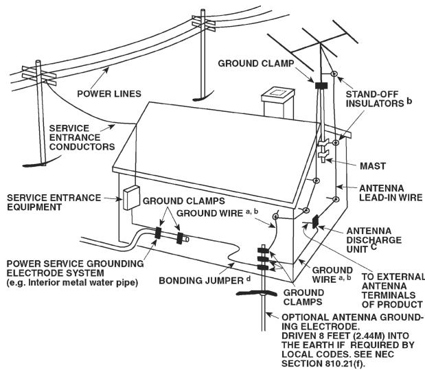
OUTDOOR ANTENNA GROUNDING
If an outside antenna is connected to your tuner or Tunerreamplifier, be sure the antenna system is grounded so as to provide some protection against voltage surges and built-up static charges. Article 810 of the National Electrical Code, ANSI/NFPA No. 70-1984, provides information with respect to proper grounding of the mast and supporting structure, grounding of the lead-in wire to an antenna discharge unit, size of grounding conductors, location of antenna discharge unit, connection to grounding electrodes and requirements for the grounding electrode.
a. Use No. 10 AWG (5.3mm2) copper, No. 8 AWG (8.4mm2) aluminium, No. 17 AWG (1.0mm2) copper-clad steel or bronze wire, or larger, as a ground wire.
b. Secure antenna lead-in and ground wires to house with stand-off insulators spaced from 4-6 feet (1.22 - 1.83 m) apart.
c. Mount antenna discharge unit as close as possible to where leadin enters house.
d. Use jumper wire not smaller than No.6 AWG (13.3mm2) copper, or the equivalent, when a separate antenna-grounding electrode is used. see NEC Section 810-21 (j).
EXAMPLE OF ANTENNA GROUNDING AS PER NATIONAL ELECTRICAL CODE INSTRUCTIONS CONTAINED IN ARTICLE 810 - RADIO AND TELEVISION EQUIPMENT.
NOTE TO CATV SYSTEM INSTALLER: This reminder is provided to call the CATV system installer's attention to Article 820-40 of the National Electrica I Code that provides guidelines for proper grounding and, in particular, specifies that the ground cable ground shall be connected to the grounding system of the building, as close to the point of cable entry as practical.
OWNER'S RECORD
For your convenience, record the model number and serial number (you will find them on the rear of your set) in the space provided below. Please refer to them when you contact your dealer in case of difficulty.
Model No.:
Serial No.:
REAR PANEL CONNECTIONS
FRONT PANEL CONTROLS
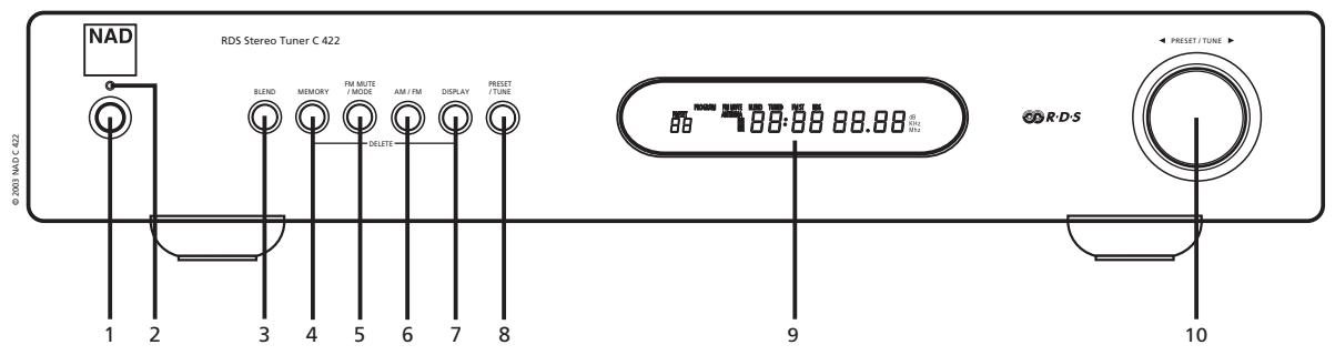
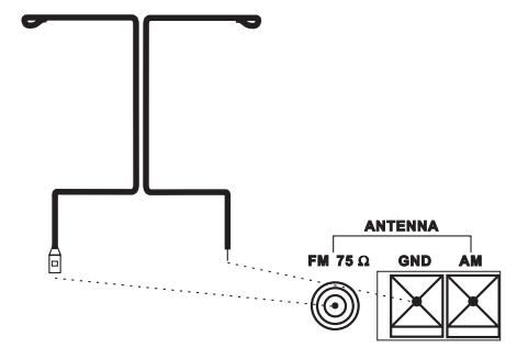
FIGURE 1. European and Australian models
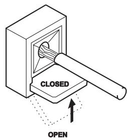
FIGURE 2.
U.S.A. And Canadian models
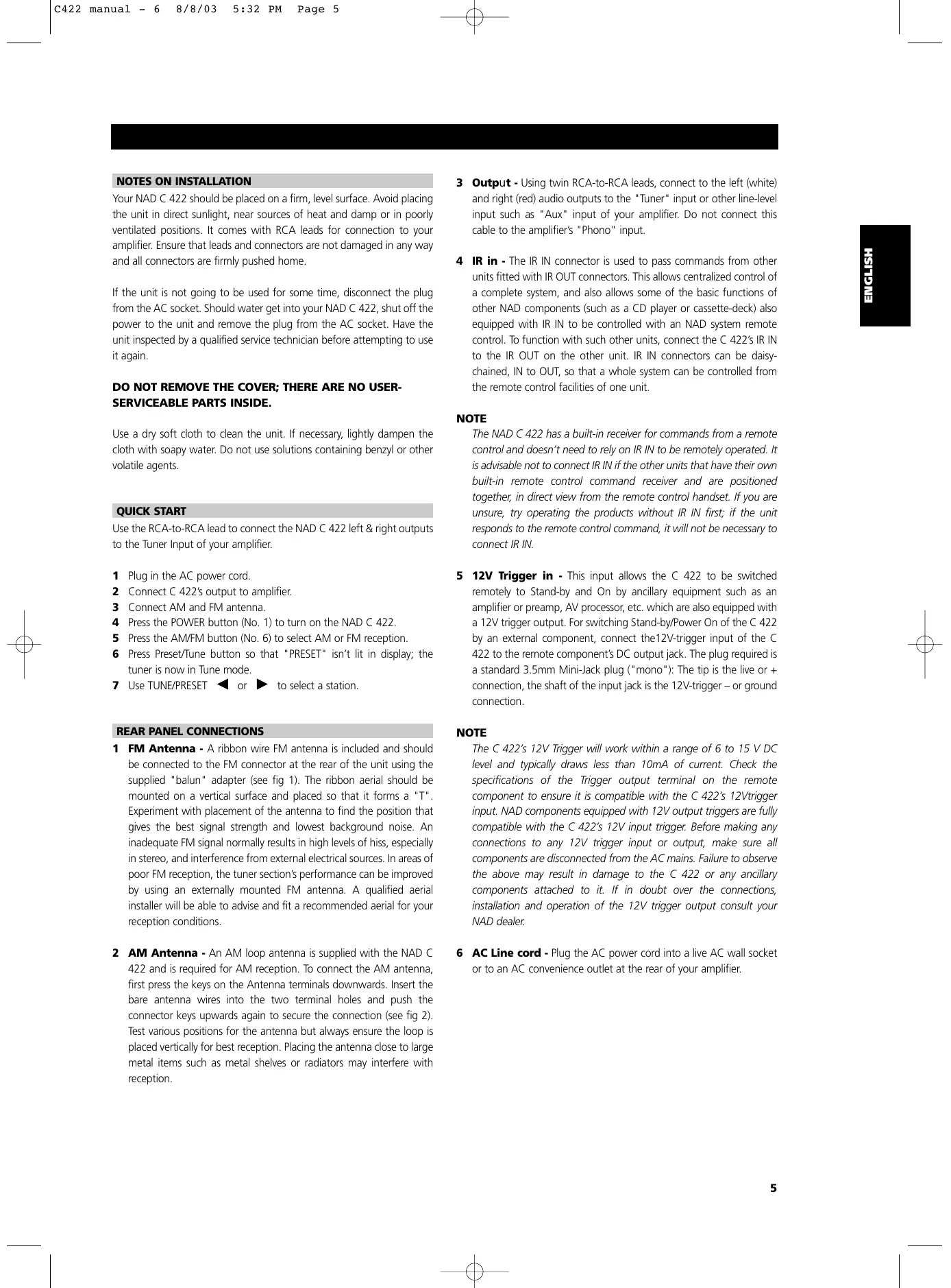
NOTES ON INSTALLATION
Your NAD C 422 should be placed on a firm, level surface. Avoid placing the unit in direct sunlight, near sources of heat and damp or in poorly ventilated positions. It comes with RCA leads for connection to your amplifier. Ensure that leads and connectors are not damaged in any way and all connectors are firmly pushed home.
If the unit is not going to be used for some time, disconnect the plug from the AC socket. Should water get into your NAD C 422, shut off the power to the unit and remove the plug from the AC socket. Have the unit inspected by a qualified service technician before attempting to use it again.
DO NOT REMOVE THE COVER; THERE ARE NO USER-SERVICEABLE PARTS INSIDE.
Use a dry soft cloth to clean the unit. If necessary, lightly dampen the cloth with soapy water. Do not use solutions containing benzyl or other volatile agents.
QUICK START
Use the RCA-to-RCA lead to connect the NAD C 422 left & right outputs to the Tuner Input of your amplifier.
1 Plug in the AC power cord.
2 Connect C 422's output to amplifier.
3 Connect AM and FM antenna.
4 Press the POWER button (No. 1) to turn on the NAD C 422.
5 Press the AM/FM button (No. 6) to select AM or FM reception.
6 Press Preset/Tune button so that "PRESET" isn't lit in display; the tuner is now in Tune mode.
7 Use TUNE/PRESET or to select a station.
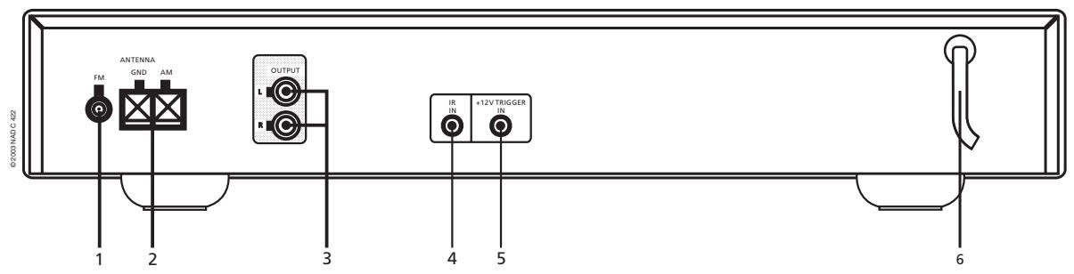
REAR PANEL CONNECTIONS
1 FM Antenna - A ribbon wire FM antenna is included and should be connected to the FM connector at the rear of the unit using the supplied "balun" adapter (see fig 1). The ribbon aerial should be mounted on a vertical surface and placed so that it forms a "T". Experiment with placement of the antenna to find the position that gives the best signal strength and lowest background noise. An inadequate FM signal normally results in high levels of hiss, especially in stereo, and interference from external electrical sources. In areas of poor FM reception, the tuner section's performance can be improved by using an externally mounted FM antenna. A qualified aerial installer will be able to advise and fit a recommended aerial for your reception conditions.
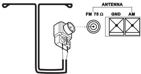
2 AM Antenna - An AM loop antenna is supplied with the NAD C 422 and is required for AM reception. To connect the AM antenna, first press the keys on the Antenna terminals downwards. Insert the bare antenna wires into the two terminal holes and push the connector keys upwards again to secure the connection (see fig 2). Test various positions for the antenna but always ensure the loop is placed vertically for best reception. Placing the antenna close to large metal items such as metal shelves or radiators may interfere with reception.
3 Output - Using twin RCA-to-RCA leads, connect to the left (white) and right (red) audio outputs to the "Tuner" input or other line-level input such as "Aux" input of your amplifier. Do not connect this cable to the amplifier's "Phono" input.
4 IR in - The IR IN connector is used to pass commands from other units fitted with IR OUT connectors. This allows centralized control of a complete system, and also allows some of the basic functions of other NAD components (such as a CD player or cassette-deck) also equipped with IR IN to be controlled with an NAD system remote control. To function with such other units, connect the C 422's IR IN to the IR OUT on the other unit. IR IN connectors can be daisy-chained, IN to OUT, so that a whole system can be controlled from the remote control facilities of one unit.
NOTE
The NAD C 422 has a built-in receiver for commands from a remote control and doesn't need to rely on IR IN to be remotely operated. It is advisable not to connect IR IN if the other units that have their own built-in remote control command receiver and are positioned together, in direct view from the remote control handset. If you are unsure, try operating the products without IR IN first; if the unit responds to the remote control command, it will not be necessary to connect IR IN.
5 12V Trigger in - This input allows the C 422 to be switched remotely to Stand-by and On by ancillary equipment such as an amplifier or preamp, AV processor, etc. which are also equipped with a 12V trigger output. For switching Stand-by/Power On of the C 422 by an external component, connect the 12V-trigger input of the C 422 to the remote component's DC output jack. The plug required is a standard 3.5mm Mini-Jack plug ("mono"): The tip is the live or + connection, the shaft of the input jack is the 12V-trigger – or ground connection.
NOTE
The C 422's 12V Trigger will work within a range of 6 to 15 V DC level and typically draws less than 10mA of current. Check the specifications of the Trigger output terminal on the remote component to ensure it is compatible with the C 422's 12V trigger input. NAD components equipped with 12V output triggers are fully compatible with the C 422's 12V input trigger. Before making any connections to any 12V trigger input or output, make sure all components are disconnected from the AC mains. Failure to observe the above may result in damage to the C 422 or any ancillary components attached to it. If in doubt over the connections, installation and operation of the 12V trigger output consult your NAD dealer.
6 AC Line cord - Plug the AC power cord into a live AC wall socket or to an AC convenience outlet at the rear of your amplifier.
FRONT PANEL CONTROLS
1 Power On/Off - POWER switches the tuner on or off. Pressing the Power switch turns the Tuner on, the Display Panel and Power Status Indicator (No. 2) will light up. Pressing the Power button again will switch the unit off.
NOTE
The C 422 has a receiver for remote control commands built-in. Most NAD system remote control handsets with an On/Off toggle button or separate On and Off button will be able to switch the tuner from On to Stand-by and vice-versa.
The C 422 uses a memory back-up system to store Preset information. This information is retained for several weeks, even if the unit is switched off completely or unplugged. When switching power On, the C 422 will go back to the station last tuned to before the unit was turned off. This will allow you to make timer recordings using an external timer and recorder.
2 Power Status Indicator - The Power Status Indicator will light up green when Power is on. When the tuner is switched to Stand-by mode (through either a remote control or the 12V trigger input) the indicator will light up amber. When the unit is switched off completely, it is off.
3 Blend - Weak or remote stereo radio stations are sometimes received with noise and hiss as the antenna signal is too weak. By switching the tuner to mono will reduce the amount of noise and hiss but at the expense of any stereo information. The NAD Blend feature will allow you to reduce the amount noise and hiss but still retain some level of stereo separation, instead of mono. The Blend button toggles between engaging or disengaging the Blend feature; when engaged, "BLEND" lights up in the display.
NOTE
The "Blend" status can be stored for individual presets. Refer to the separate chapter "Storing, Recalling and Labelling Presets" for more information.
4 Memory - The Memory is used to store stations into the Preset Memory bank and to store user defined names for non-RDS Preset stations. When Memory is pressed during normal operation, the Preset number and the red "MEMORY" indicator will flash in the Display Panel. If no other buttons are pressed within 12 seconds, the tuner will revert to its previous state. Refer to the separate chapter "Storing, Recalling and Labelling Presets" for more information.
5 FM Mute/Mode - This button combines two functions; it switches the tuner from Stereo to Mono and disengages the muting circuitry at the same time. The muting circuit will mute the tuner in between radio stations when searching or tuning. This way the tuning noise is avoided. The muting circuit however may suppress very weak radio station signals. If a weak station is in stereo it will have a high level of background hiss. Switching to Mono Mode and disengaging the muting circuit by depressing the FM MUTE/MODE button will allow the station to be heard and will cancel most or all of this background noise.
In normal operation the mute circuit is engaged, the display indicates "FM MUTE". Press the FM Mute/Mode button to disengage the muting circuit and switch from stereo to mono reception. "FM MUTE" in the display will extinguish. Press the FM Mute/Mode switch again to return to Auto Stereo FM operation.
NOTE
The "FM Mute/Mode" status can be stored for individual presets. Refer to the separate chapter "Storing, Recalling and Labelling Presets" for more information.
6 AM/FM - The AM/FM button switches the tuner from the AM band to the FM band and vice-versa. The Display Panel shows the frequency of the tuned station and which band is selected. The FM tuning is in 0.05 MHz increments, AM tuning is in 9 kHz or 10 kHz increments, depending on the version.
7 Display - With stations carrying RDS information, The Display button scrolls between three different display modes, each successive push of the button engages the next one of the three modes:
a) In the default mode, the station's RDS name is displayed, Program Service (PS; normally the station's calling letters, BBC R3, for instance).
b) From the default mode, press the button once to view Radio Text (RT). This can be additional information such as the presenter's or program's name; what song is playing, etc. This text scrolls continuously over the 8 alphanumeric display segments.
c) Press the button from the display RT mode to display the station frequency. Press again to return to the default mode (a).
When tuned to a non-RDS station - The Display button toggles the display to show either the station frequency or user entered station name. If no user name was entered the display will indicate "NO RDS". The Display button is also used to label non-RDS stations with a name. Refer to the separate chapter "Storing, Recalling and Labelling Presets" for more information.
8 Preset/Tune - The Search/Preset button toggles between two different modes:
a) Preset mode: In this mode you can use the Tune/Preset button (No. 10) to select a Preset. When Preset Mode is selected "PRESET" will scroll once through the display and the PRESET indicator lights up in the display.
b) Tune mode: By rotating the Preset/Tune control (10) or you can engage automatic or manual tuning respectively down or up the frequency band. When Tune mode is selected, "TUNE" will scroll through the display once.
9 Display Area - The display area gives all vital information on the status of the tuner. Displayed are:
- Band and frequency of current station, RDS PS (station name), or RDS Radio Text. The latter two only if RDS is available; select using the Display button (No. 7).
If an FM Stereo broadcast is received. - If the FM station also broadcasts RDS.
- If "Memory" has been engaged
- Preset number if the current station is stored in the tuner's memory bank.
- If Blend and FM Mute/Mode are switched On.
- Radio Signal Strength. The bars just below "ANTENNA" indicate the radio station's signal strength. The more bars are lit, the stronger the station.
NOTE
The infrared sensor, which receives commands from a remote control (not supplied), is located on the left side of the display window. There must be a clear line-of-sight path from the remote control to this window; if that path is obstructed, the remote control may not work.
10 Preset/Tune Control - The function of this control depends on the tuning mode selected with the Preset/Tune button (No. 8). The PRESET/TUNE Control operates when the rotational switches are engaged; either clockwise or counter clockwise, and the contact switches are engaged. The Preset/Tune button toggles between the two operational modes:
a) Preset mode (indicated in the display area): Rotate the Preset/Tune control to the left to scroll to a lower number Preset; rotate the Preset/Tune control to the right to scroll to a higher Preset number. This is a "wrap-around" function, so that going from the highest number Preset, the tuner will go to the lowest Preset number or vice-versa either up or down when tuning.
b) Tune mode: Rotate the Preset/Tune control in either direction for more than 1 second to engage automatic tuning respectively up or down the frequency band. The tuner will search automatically for the first reasonably strong radio station, where it will stop. Rotate the Preset/Tune control again for 1 second to start searching again.
By briefly rotating the Preset/Tune control in either direction you will engage manual tuning respectively up or down the frequency band for precise tuning to a specific frequency. With each brief rotation, the tuner will take 0.05 MHz steps on FM so you can accurately tune into the desired frequency. For AM the tuning steps are set at 10 kHz (120V version) or 9 kHz (230V version).
This tuning mode can also be useful when trying to receive a radio station, which is too weak for the auto search mode. When tuned accurately to a station, "TUNED" will light up in the display. The muting circuit however may suppress very weak radio station signals. If such a very weak station is in stereo it will have a high level of background hiss. Switching to Mono Mode and disengaging the muting circuit by depressing the FM MUTE/MODE button (No. 5) will allow the station to be heard and will cancel most or all of this background noise.
NOTES
Automatic tuning is available on both FM and AM.
Some NAD system remote controls, compatible with the NAD C 422, have Preset Up and Down functions. Even if the C 422 is in Tune Mode, this remote control's Preset Up and Down buttons will only change presets. The Preset/Tune and buttons are also used in conjunction with the Memory (No. 4) and Display (No. 7) buttons to add and memorise user defined names to Presets. Refer to the separate chapter "Storing, recalling and naming Presets" for more information.
STORING, RECALLING AND LABELLING PRESETS
Up to 30 presets in total can be stored in the C 422's memory bank; these can be any mix of either AM or FM stations. When scrolling through the presets, empty preset places will be skipped; it is thus possible to go from preset No. 4 to No. 7 without having seen No. 5 and 6. With the presets you can also store whether you want Blend (No. 3) and FM Mute/Mode (No. 5) to be activated as well every time you recall the preset.
To Store a Preset
- Tune to the radio station you wish to enter into a Preset (refer to this chapter's section 10). If the station is transmitting RDS information, the RDS indicator will light up and station initials or name will be shown in the Display Panel. If a non-RDS station is found, then just the frequency will be shown.
- Select Blend (No. 3) or FM Mute/Mode (No. 5) if desired.
- To store that station as a Preset, press Memory (No. 4). The Preset number and the red "MEMORY" indicator are flashing in the Display Panel. The lowest available empty preset number will be shown. If no other buttons are pressed within 12 seconds, the tuner will revert to its previous state.
- Press Memory again to store the preset. If you wish to assign a different preset number, rotate the Preset/Tune control left or right to select the desired preset number. You can overwrite an existing preset. If the preset number already has been assigned, "MEMORY" will stop blinking, but the preset will continue to blink. When you have selected the desired preset number, press Memory again to store the station.
NOTE
You can enter a new station into an unused Preset or over-write an existing programmed Memory Preset. By doing this you will replace all the data previously held on that Preset number. When Memory is pressed during normal operation, the Preset number and the red "MEMORY" indicator will flash in the Display Panel. If no other buttons are pressed within 12 seconds, the tuner will revert to its previous state. The Memory Presets have a memory back-up, so they will remain stored for several weeks even if the Tuner is switched off or unplugged from the mains supply.
RECALLING A PRESET
- To select a Preset station, the C 422 must be in the Preset mode (the display indicates "PRESET"). If not, press the Preset/Tune Mode button (No. 8); "PRESET" will now light up in the display.
- Rotate the Tune/Preset control (No. 10) in either direction until the right Preset is found and shown in the Display Panel. Any unused Presets will be skipped; this avoids having to scroll through empty presets.
DELETING A STORED PRESET
You can empty a Preset by deleting the stored information:
- Select the Preset to be emptied.
- Press and hold the Memory button (No. 4) and Display button (No.7) for two seconds. The preset number and the text "DELETE" will flash in the display.
- Press only the display button again (within default time of 5 seconds) to confirm you want to delete this preset. The text "DELETED" and "—" as the Preset number appear in the display for a couple of seconds.
LABELLING A PRESET
When a station is transmitting RDS information, your NAD C 422 will automatically show the station initials when its Preset is used. Although the Tuner automatically shows the frequency of any other AM or non-RDS Preset station, it also allows you to type in the station name to make it easier to identify which station is stored in the Memory Preset.
To enter a name:
1 Select the Preset you want to attach a name to.
2 Press and hold the Display button (No. 7) for two seconds. The first space in the Station Data area of the Display Panel will flash.
3 Rotate the Tune / Preset control (No. 10) in either direction to scroll and select the first character (see Character list below for reference).
4 Press Display to move one place to the right to enter the next desired character.
5 Rotate the Tune/Preset control again to select the next character in the name and press Memory to store it.
6 Repeat steps 3 to 5 until name is complete or all eight places have been filled (up to 8 characters).
7 Press Memory once to finish the labelling procedure. Press Memory again to store the completed name.
There are 37 characters available including a blank space.
| SPACE | A | B | C | D | E | F | G | H | I |
| J | K | L | M | N | O | P | Q | R | S |
| T | |||||||||
| T | U | V | W | X | Y | Z | 0 | 1 | 2 |
| 3 | 4 | 5 | 6 | 7 | 8 | 9 |
NOTE
This function is available only for non-RDS stations. RDS Stations will always display their transmitted name and cannot be over-written.
SETUP FOR CUSTOM AND MULTI-ZONE INSTALLATIONS
REMOTE CONTROL CODES
The NAD C 422 has a remote control command receiver built in so it will respond to NAD remote control commands, such as from most NAD system remote controls (SR-4, SR-5, S70; not supplied with C 422). This will allow access to basic functions such as preset up/down, On/Stand-by.
Particularly with Custom Install in mind, the NAD C 422 will respond to other commands not usually found on NAD remote control handsets. The table below indicates all commands the C 422 recognises.
The NAD C 422 uses the NEC format for IR transmission; customer code is 877C, the corresponding hex codes are next to the IR command:
| Footnote | Function | Hex Code |
| 1 | Preset ▲ | D2 |
| Preset ▲ | D1 | |
| 2 | Search ▲ | 87 |
| Search ▲ | 86 | |
| 3 | Tune ▲ | D4 |
| Tune ▲ | D3 | |
| 4 | Preset 1 | 8A |
| Preset 2 | 8E | |
| Preset 3 | 92 | |
| Preset 4 | 94 | |
| Preset 5 | 8B | |
| Preset 6 | 8F | |
| Preset 7 | 03 | |
| Preset 8 | 97 | |
| Preset 9 | 98 | |
| Preset 0 | C7 | |
| 5 | Enter | C5 |
| 6 | Power/standby toggle | 80 |
| 7 | Power On | 25 |
| 8 | Standby | C8 |
1 Preset and scroll trough presets, with wrap-around.
2 Search and will engage auto-searching, with wrap-around.
3 Tune and will engage tuning. if command received for more than 1 second, auto-search is engaged; wrap around
4 Preset 1-9, 0: Allows direct entry of preset number. First send desired number code, send Enter code to confirm. If preset is empty, tuner will default to current status.
5 Enter: To confirm and engage preset number. Program small macro with preset 1-9,0 and enter to gain direct preset access.
6 Power/Stand-by toggle: Switches tuner from On to Stand-by and vice-versa. This code is also used on other re mote controlled products.
7 Power On: To avoid sync problems with other NAD products also using the Power/Stand-by toggle, the C 422 responds to separate On code in addition; if already switched on, it will remain on.
8 Stand-by: For same reason as above. If already in Stand-by mode, it will remain so.
12V TRIGGER INPUT
NAD components equipped with 12V output triggers are fully compatible with the C 422's 12V input trigger.
Plug type: 3.5mm mono mini-jack
Operating range: 6 to 15 V DC
Current drawn: <10mA
Centre pin = +
Shaft =
TROUBLESHOOTING
| PROBLEM | CAUSE | SOLUTION |
| NO SOUND | • Power AC lead unplugged or power not switched on • Signal leads incorrectly connected • Station not selected or weak signal with FM Mute on • Internal fuse blown | • Check AC lead • Check connections to amplifier • Re-tune or switch off FM Mute • Consult dealer |
| NO SOUND IN ONE CHANNEL | • Signal leads to amplifier disconnected or damaged | • Check leads and connections |
| NOISE, HISs | • Weak signal | • Check station tuning. Adjust or replace antenna |
| DISTORTION | • Multi-path signals or interference from another station | • Check station tuning. Adjust or replace antenna |
| WHISTLES OR BUZZES ON FM & AM | • Interference from other electrical sources:- computers, games consoles | • Check station tuning. Switch off or move the source of the electrical noise |
| WHISTLES OR BUZZES ON AM | • Interference from fluorescent lighting or electrical motors | • Check station tuning. Adjust or replace AM antenna |
| NO RDS INFORMATION | • Station signal too weak • Station not transmitting RDS data | • Check station tuning Adjust or replace antenna • No remedy |
SPECIFICATIONS
AM TUNER SECTION
| Usable Sensitivity (999/1000kHz) | 30dBμ |
| S/N Ratio (5mV in) | 38dB |
| THD (5mV in) | 3% |
| IF Rejection (450kHz) | 36dB |
| Image Rejection (F+2xIF) | 28dB |
| Selectivity | 17dB |
| Output | 130 mV ±20mV |
| Loop Sensitivity (20dB S/N) | |
| 999/1000 kHz | 66 dB |
| 603/600 kHz | 66 dB |
| 1404/1400 kHz | 66 dB |
| Frequency response (100 - 2.3 kHz, 5mV) | ±6 dB |
FM TUNER SECTION European Version / North American Version
| Usable Sensitivity (98 MHz) | 13 dBμ / 13 dBμ |
| Signal / Noise Ratio Mono | 72 dB / 72 dB |
| (60 dBμ, IHF wtd) Stereo | 66 dB / 66 dB |
| Frequency Response (20 Hz - 15 kHz, 60 dBμ) | ±1.0 dB / ±1.0 dB |
| Channel Separation (60 dBμ) | |
| 30 Hz | 33 dB / 33 dB |
| 1 kHz | 42 dB / 42 dB |
| 10 kHz | 32 dB / 32 dB |
| Alternate Channel Sensitivity (40 dBμ, ±400 kHz) | 60 dB / 45 dB |
| Capture Ratio (40 dBμ) | 3 dB / 3 dB |
| AM Suppression (60 dBμ, 100% Mod.FM, 30% Mod.AM) | 65 dB / 65 dB |
| Image Rejection (119.4 MHz) | 85 dB / 85 dB |
| I.F. Rejection (10.7 MHz) | 78 dB / 78 dB |
| Pilot Suppression (60 dBμ) | 60 dB / 60 dB |
| THD (60 dBμ, L=R 75 kHz for AH, 40 kHz Dev for C) | |
| Mono | 0.25% / 0.25% |
| Stereo | 0.35% / 0.35% |
| Auto-Search | |
| Sensitivity On | 24 dBμ / 24 dBμ |
| Sensitivity Off | 15 dBμ / 15 dBμ |
| RDS Decode Sensitivity | 26 dBμ, 26 dBμ |
PHYSICAL SPECIFICATIONS
| Dimensions (Width x Height x Depth) | 435 x 80 x 285 mm (17.12 x 3.15 x 11.22 inches) |
| Net weight | 4 kg (8.8 lbs) |
| Shipping weight | 5.1 kg (11.22 lbs) |
NAD reserves the right to change specifications without notice.
NOTES CONCERNANT L'INSTALLATION
| H | B | C | D | E | F | G | H | I | |
| SPACE | A | B | C | D | E | F | G | H | I |
| K | L | M | N | O | P | Q | R | S | |
| J | K | L | M | N | O | P | Q | R | S |
| T | L | L | L | V | V | T | L | I | L |
| I | L | L | L | V | I | L | L | I | L |
| T | U | V | W | X | Y | Z | 0 | 1 | 2 |
| 3 | 4 | 5 | 6 | 7 | 8 | 9 | |||
| 3 | 4 | 5 | 6 | 7 | 8 | 9 |
NOTA
| A | B | C | D | E | F | G | H | I | |
| SPACE | K | L | M | N | O | P | Q | R | S |
| J | K | L | M | N | O | P | Q | R | S |
| T | U | V | W | X | Y | Z | 0 | 1 | 2 |
| 3 | 4 | 5 | 6 | 7 | 8 | 9 |
HINWEIS
| H | B | C | D | E | F | G | H | I | |
| SPACE | A | B | C | D | E | F | G | H | I |
| K | L | M | N | O | P | Q | R | S | |
| J | K | L | M | N | O | P | Q | R | S |
| T | L | L | L | V | V | T | L | I | L |
| I | L | L | L | V | I | L | L | I | L |
| T | U | V | W | X | Y | Z | 0 | 1 | 2 |
| 3 | 4 | 5 | 6 | 7 | 8 | 9 |
N.B.:
| H | B | C | D | E | F | G | H | I | |
| SPACE | A | B | C | D | E | F | G | H | I |
| K | L | M | N | O | P | Q | R | S | |
| J | K | L | M | N | O | P | Q | R | S |
| T | L | L | L | V | V | 7 | 7 | 1 | 7 |
| I | L | L | L | V | I | 7 | 7 | 1 | 7 |
| T | U | V | W | X | Y | Z | 0 | 1 | 2 |
| 3 | 4 | 5 | 6 | 7 | 8 | 9 |
NOTA
| H | B | L | I | E | F | G | H | I | |
| SPACE | A | B | C | D | E | F | G | H | I |
| K | L | M | N | O | P | Q | R | S | |
| J | K | L | M | N | O | P | Q | R | S |
| T | L | I | I | V | V | I | I | I | I |
| I | L | I | I | V | I | I | I | I | I |
| T | U | V | W | X | Y | Z | 0 | 1 | 2 |
| 3 | 4 | 5 | 6 | 7 | 8 | 9 |
NOTA
| H | B | C | D | E | F | G | H | I | |
| SPACE | A | B | C | D | E | F | G | H | I |
| K | L | M | N | O | P | Q | R | S | |
| J | K | L | M | N | O | P | Q | R | S |
| T | L | L | L | V | V | 7 | 7 | 1 | 2 |
| U | U | V | W | X | Y | Z | 0 | 1 | 2 |
| 4 | 5 | 6 | 7 | 8 | 9 | ||||
| 3 | 4 | 5 | 6 | 7 | 8 | 9 |
NOTA
| A | B | C | D | E | F | G | H | I | |
| SPACE | K | L | M | N | O | P | Q | R | S |
| T | U | V | W | X | Y | Z | 0 | 1 | 2 |
| 3 | 4 | 5 | 6 | 7 | 8 | 9 |
OBSERVERA
www.NADelectronics.com