412 - Audio Receiver NAD - Free user manual and instructions
Find the device manual for free 412 NAD in PDF.
| Brand | NAD |
| Model | 412 |
| Product Type | Audio Receiver (FM/AM Tuner) |
| Frequency Bands | FM (Frequency Modulation) and AM (Medium Wave) |
| Number of Presets | 24 (12 FM + 12 AM) |
| FM Antenna Input | 75 ohm coaxial (300/75 balun adapter included) |
| AM Antenna Terminal | Screw terminals for long wire antenna (up to 30 m) |
| Audio Output | Stereo RCA/Cinch jack |
| Control Network | NAD Link (input/output for unified remote control) |
| Power Supply | Mains (power cord) |
| Power Consumption | Not specified (internal power transformer) |
| Dimensions (W x D x H) | Not specified (standard hi-fi tuner size) |
| Weight | Not specified |
| Main Functions | Manual tuning, auto seek, presets, mono mode, blend, lock, store |
| Display | Digital (frequency and preset number) |
| Indicator Lights | Tuned (green) for FM, FM Stereo (orange), standby |
| Care and Cleaning | Do not expose to moisture; unplug if spilled; refer all repairs to qualified personnel |
| Safety | Do not open, do not modify; use a lightning arrestor for outdoor antenna; avoid placing on soft surfaces that obstruct ventilation |
| Supplied Accessories | FM dipole antenna (flat cable), 300/75 balun adapter, AM antenna (approx. 1 m wire) |
| Reparability / Spare Parts | Not specified; in case of defect, contact an authorized NAD dealer |
Frequently Asked Questions - 412 NAD
User questions about 412 NAD
0 question about this device. Answer the ones you know or ask your own.
Ask a new question about this device
Download the instructions for your Audio Receiver in PDF format for free! Find your manual 412 - NAD and take your electronic device back in hand. On this page are published all the documents necessary for the use of your device. 412 by NAD.
USER MANUAL 412 NAD
WARNING:TO PREVENT FIRE OR ELECTRIC SHOCK,DO NOT EXPOSE THIS APPLIANCE TO RAIN OR MOISTURE
Note to CATV system Installer: This reminder is provided to call the CATV installer's attention to Article 820-40 of the NEC, which provides guidelines for proper grounding and, in particular, specifies that the cable should be connected to the grounding system of the building, as close to the point of cable entry as practical.
CAUTION: TO PREVENT ELECTRIC SHOCK DO NOT USE THIS POLARISED PLUG WITH AN EXTENSION CORD RECEPTACLE OR OTHER OUTLET UNLESS THE BLADES CAN BE FULLY INSERTED TO PREVENT BLADE EXPOSURE.
ATTENTION: POUR PREVENIR LES CHOCS ELECTRIQUES NE PAS UTILISER CETTE FICHE POLARISEE AVEC UN PROLONGATEUR, UNE PRISE DE COURANT OU UNE AUTRE SORTIE DE COURANT, SAUF SI LES LAMES PEUVENT ETRE INSEREES A FOND SANS EN LAISSER AUCUNE PARTIE A DECOUVERT.

CAUTION
REX OF ELECTRIC
SHOCK DO NOT LIKE

CAUTION TO REDUCE THE BISK OF ELECTRIC
SHOCK DO NOT REMOVE COVER OR BACK
NOUSERSEVOCABLEPARTSINSID
REFER SERVICING TO QUALIFIED
SERVICE PERSONNEL
ATTENTION:
HISQULCHUGLCHIGUE
MEPASOUVIN
AFIN DEVTTER UN CHOC
ELECTRIQUE,ETLES
CONSEQUENCES GRAVES
QUIPOURPAIENT EN
RESOLUTER TEMPEZ PAS
VOCVARTAPP
DETOUCHER AUX
COMPOSANTS INTERNES
SANS LA PRESENCE D'UNE
REVCHE PERSONEL

The lightning flash with arrowhead, within an equilateral triangle is intended to alert the user of the presence of uninsulated "dangerous voltage" within the product's enclosure; that may be of sufficient magnitude to constitute a risk of electric shock to persons.

The exclamation point within an equilateral triangle is intended to alert the user of the presence of important operating and maintenance (servicing) instructions in the literature accompanying the appliance
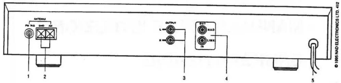
REAR PANEL CONNECTIONS
FRONT PANEL CONTROLS
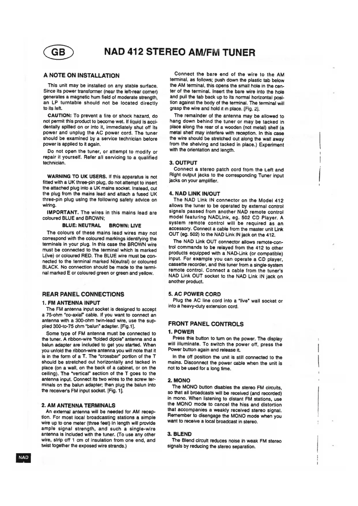
A NOTE ON INSTALLATION
This unit may be installed on any stable surface. Since its power transformer (near the left-rear corner) generates a magnetic hum field of moderate strength, an LP turntable should not be located directly to its left.
CAUTION: To prevent a fire or shock hazard, do not permit this product to become wet. If liquid is accidentally spilled on or into it, immediately shut off its power and unplug the AC power cord. The tuner should be examined by a service technician before power is applied to it again.
Do not open the tuner, or attempt to modify or repair it yourself. Refer all servicing to a qualified technician.
WARNING TO UK USERS. If this apparatus is not fitted with a UK three-pin plug, do not attempt to insert the attached plug into a UK mains socket. Instead, cut the plug from the mains lead and attach a fused UK three-pin plug using the following safety advice on wiring.
IMPORTANT. The wires in this mains lead are coloured BLUE and BROWN;
BLUE:NEUTRAL BROWN:LIVE
The colours of these mains lead wires may not correspond with the coloured markings identifying the terminals in your plug. In this case the BROWN wire must be connected to the terminal which is marked L(ive) or coloured RED. The BLUE wire must be connected to the terminal marked N(eutral) or coloured BLACK. No connection should be made to the terminal marked E or coloured green or green and yellow.
REAR PANEL CONNECTIONS
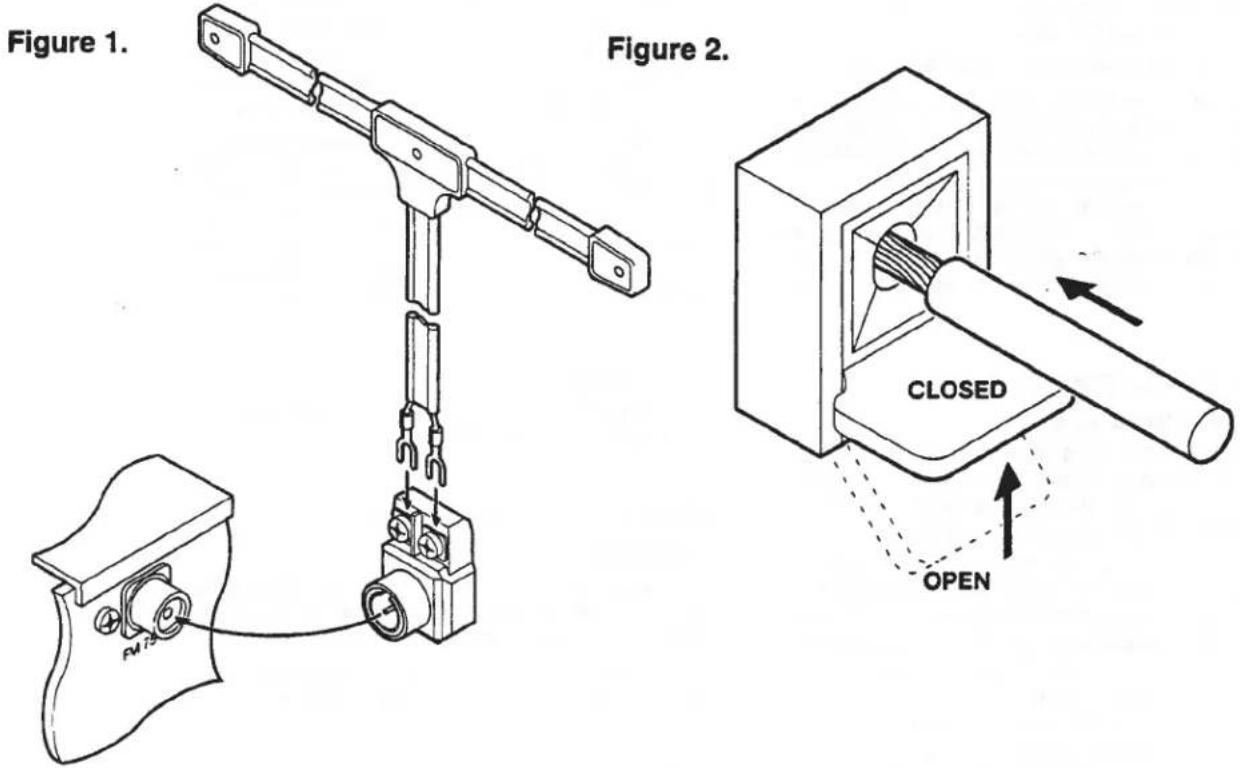
1. FM ANTENNA INPUT
The FM antenna input socket is designed to accept a 75-ohm "co-axial" cable. If you want to connect an antenna with a 300-ohm twin-lead wire, use the supplied 300-to-75 ohm "balun" adapter. [Fig.1].
Some type of FM antenna must be connected to the tuner. A ribbon-wire "folded dipole" antenna and a balun adapter are included to get you started. When you unfold the ribbon-wire antenna you will note that it is in the form of a T. The "crossbar" portion of the T should be stretched out horizontally and tacked in place (on a wall, on the back of a cabinet, or on the ceiling). The "vertical" section of the T goes to the antenna input. Connect its two wires to the screw terminals on the balun adapter; then plug the balun into the receiver's FM input socket. [Fig. 1].
2.AM ANTENNA TERMINALS
An external antenna will be needed for AM reception. For most local broadcasting stations a simple wire up to one meter (three feet) in length will provide ample signal strength, and such a single-wire antenna is included with the tuner. (To use any other wire, strip off 1 cm of insulation from one end, and twist together the exposed wire strands.)
Connect the bare end of the wire to the AM terminal, as follows; push down the plastic tab below the AM terminal, this opens the small hole in the center of the terminal. Insert the bare wire into the hole and pull the tab back up to its normal horizontal position against the body of the terminal. The terminal will grasp the wire and hold it in place. [Fig. 2].
The remainder of the antenna may be allowed to hang down behind the tuner or may be tacked in place along the rear of a wooden (not metal) shelf (a metal shelf may interfere with reception. In this case the wire should be stretched out along the wall away from the shelving and tacked in place.) Experiment with the orientation and length.
3. OUTPUT
Connect a stereo patch cord from the Left and Right output jacks to the corresponding Tuner input jacks on your amplifier.
4. NAD LINK IN/OUT
The NAD Link IN connector on the Model 412 allows the tuner to be operated by external control signals passed from another NAD remote control model featuring NADLink, eg. 502 CD Player. A system remote control will be required as an accessory. Connect a cable from the master unit Link OUT (eg. 502) to the NAD Link IN jack on the 412.
The NAD Link OUT connector allows remote-control commands to be relayed from the 412 to other products equipped with a NAD-Link (or compatible) input. For example you can operate a CD player, cassette recorder, and this tuner from a single-system remote control. Connect a cable from the tuner's NAD Link OUT socket to the NAD Link IN jack on another product.
5. AC POWER CORD
Plug the AC line cord into a "live" wall socket or into a heavy-duty extension cord.
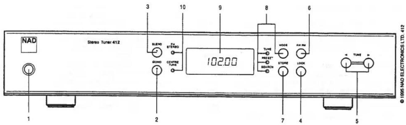
FRONT PANEL CONTROLS
1. POWER
Press this button to turn on the power. The display will illuminate. To switch the power off, press the Power button again and release it.
In the off position the unit is still connected to the mains. Disconnect the power cable when the unit is not to be used for a long time.
2. MONO
The MONO button disables the stereo FM circuits, so that all broadcasts will be received (and recorded) in mono. When listening to distant FM stations, use the MONO mode to cancel the hiss and distortion that accompanies a weakly received stereo signal. Remember to disengage the MONO mode when you want to receive a local broadcast in stereo.
3. BLEND
The Blend circuit reduces noise in weak FM stereotaxis signals by reducing the stereo separation.
It is characteristic of stereo FM that the stereo subcarrier becomes noisier as the received signal becomes weaker. When the Blend is engaged, the contribution of the stereo subcarrier to the sound is reduced, giving up some stereo separation in favour of quieter reception.
Remember to disengage the Blend for normal reception of strong signals.
4. LOCK
Pressing this button causes the tuner to search within a narrow range around the received station to optimise the signal strength and tuning
5. UP/DOWN TUNING
Press the Tune Up (▶) button to select higher frequencies or higher-numbered presets. Press the Tune Down (▲) button to select lower frequencies OR lower-numbered presets. The effect of the tuning buttons depends on the setting of the Tuning Mode selector.
In the PRESET mode, tapping the button will increase the Preset number. If you are tuned to Preset #2 and tap the button once, the receiver will tune to Preset #3. If you press the button and hold it in with continuous pressure, the tuner will scan rapidly through the presets until you release the button. The tuner has a "wrap-around" feature: if you increase the Preset number above 12, it automatically starts over again at Preset #1.
In the SEARCH mode, tapping the button will cause the tuner to scan rapidly upward in frequency and stop at the next strong signal. The button reverses the direction of SEARCH.
In the TUNE mode, tapping the button will increase the tuning frequency in steps of 0.025 MHz on the FM band. Each time the or button is tapped, the tuned frequency will shift up or down by this increment. Since only two digits are displayed after the decimal point, the sequence of steps will appear as: 94.10, 94.12, 94.15, 94.17, 94.20, etc.
On the medium-wave AM band the size of each tuning step is 10 kHz in North America, or 9 kHz in Europe.
If you hold a Tuning button down with continuous pressure rather than tapping it, the circuit pauses briefly and then scans rapidly up or down in frequency (or preset number) until the button is released.
To tune a broadcast signal, select the TUNE mode by pressing the MODE button; then press continuously on the or button until the tuned frequency is close to the desired broadcast frequency. Fine-tune in small increments by tapping either Tuning button. If you know the exact frequency of the broadcast station, simply tune to that frequency. If you don't know the exact frequency, tune to the vicinity of the correct frequency and adjust the tuning until the center-tune indicator glows. When tuning a weak signal that is only a few tuning steps away from a powerful signal, you may reduce interference by tuning slightly off from the station's center frequency, in the direction away from the stronger signal.
6. AM/FM
This button switches between the two tuning bands: FM or medium-wave AM. The digital tuning display shows the tuned frequency in MHz (for FM) or kHz (or AM).
The tuning circuit has a "last station selected" memory. When you switch between tuning bands, the circuit automatically re-tunes the last station that you were tuned to when you previously used that band.
7. MEMORY STORE
Use this button to store station frequencies in the tuner's 24 presets (12 AM and 12 FM). The procedure is as follows:
(1) Select FM or AM, as appropriate.
(2) Decide what preset number you wish to assign to each station. Each preset can be assigned to only one station on each band, but you can assign the same station to several presets.
(3) Tune to a station, by pressing the up/down tuning buttons or by selecting the station frequency on the remote control's numeric keypad. Press STORE to store the frequency. Press the or button to select a preset number. Press STORE to assign the stored frequency to that preset.
(4) Repeat this process for each station, up to a maximum of 12 on each band.
8. TUNING MODE
Tap the MODE button repeatedly to select one of three tuning modes: Tune, Preset, Search.
In the TUNE mode you can tune station frequencies directly by pressing the (Up) or (Down) tuning button.
In the PRESET mode, tapping the or tuning button advances to the next higher or lower-numbered preset.
In the SEARCH (auto-seek) mode, tapping the or tuning button causes the tuner to scan rapidly up or down in frequency and stop at the next station.
If you press one of the up/down SEARCH, TUNE, or PRESET buttons on the remote control, the tunes shifts to the corresponding mode.
9. TUNING DISPLAY
The numeric display shows the broadcast frequency to which the tuner is tuned. When you tune to a station the display blinks for about three seconds, alternately showing the frequency and the preset number.
10. TUNING INDICATORS
The green CENTRE TUNE Indicator glows when the tuner is tuned to the center of an FM station's broadcasting channel.
The amber FM STEREO indicator illuminates when a stereo FM broadcast is being received and decoded by the tuner's multiplex decoder circuit. Note that if the MONO button is engaged, all broadcasts will be received in mono. Also, if you have mis-tuned away from the center of a station's broadcast channel, the
GB
stereo decoding circuits may not lock onto the signal and it may be received only in mono.
APPENDIX:GETTING THE BEST PERFORMANCE FROM THE NAD 412 STORING STATION FREQUENCIES IN THE TUNING PRESETS
(1) Decide which station you want to assign to each of the 12 presets. (You don't have to use them all.) You may arrange the stations in any order that you find easy to remember or convenient to use. For example the arrangement may be alphabetical (1 = WABC, 2 = WCBS, 3 = WNYC ) , numerical (1 = BBC1, 2 = BBC2, ) , or in order of increasing frequency (1 = 89.7, 2 = 90.9, 3 = 92.3 , etc).
(2) Select the FM or AM band.
(3) Tune to the first station on your list, by pressing the up/down tuning buttons. If you are not certain of the frequency, check the station/frequency directory in a local newspaper or broadcasting guide.
Press STORE to store the displayed frequency in the tuner's memory. The tuner will display E01. Press STORE to register the stored frequency as Pre-set 01.
(4) Tune to the second station on your list. Press STORE to store that frequency. The tuner will display E01, the last preset selected. Press to advance the preset number. When it displays E02, press STORE to complete the second pre-set.
(5) Tune to the third station on your list, press STORE to store the frequency, press to select Preset 03, and press STORE again to complete the third entry.
Continue with this process until you have stored as many stations as you wish. 12 presets are provided for FM stations and another 12 presets for the AM medium-wave band. After you finish programming the pre-sets, you may wish to post your list of stations and associated pre-set numbers nearby for reference.
Incidentally, if you make a mistake or change your mind, it is not necessary to re-program the pre-sets in sequence. You can re-program any pre-set as follows:
Tune to the desired frequency, press STORE, press or to select the preset number that you want to re-program, and press STORE again.
The pre-sets preserve their frequency assignments forever, even if the AC power cord is unplugged. Thus you can re-arrange your stereo system, or move the equipment from room to room, without losing the pre-set frequencies.
TO CHANGE THE AM TUNING STEP
When tuning on the AM medium-wave band, the frequency changes by increments of 10kHz in North America and 9kHz in Europe. The following procedure toggles the tuning circuit between these settings.
(1) Press the MODE button and hold it in.
(2) While continuing to press MODE, press the▶ (Tune Up) button.
(3) Release the (Tune Up) button.
(4) Release the MODE button.
TO CLEAR THE MEMORY
The following procedure will erase all frequencies from the presets.
(1) Press the POWER button and hold it in.
(2) While continuing to press the POWER button, press STORE for 2 seconds.
(3) Release the STORE button.
(4) Release the POWER button.
ANTENNAS FOR BETTER RECEPTION
A ribbon-wire "dipole" antenna may provide adequate reception of strong FM signals. But such an antenna is not very efficient at rejecting "multipath" and other forms of FM interference. And it cannot easily be rotated to optimize its pickup pattern for best reception of stations in different directions.
In most cases reception can be improved upon by using an outdoor antenna. The best choice is a directional FM-only antenna, mounted as high above ground as is practical, and separated by at least two meters (7 feet) vertically or horizontally from any other antenna. We would suggest you contact your local aerial installation company to advise you and install your FM aerial.
If you install an outdoor antenna yourself, observe these important CAUTIONS:
(1) Do not mount the antenna close to electric power lines. Plan the installation so that the antenna mast cannot fall into contact with power lines, either while you are installing it or later.
(2) Include a lightning arrester in the installation, to protect both yourself and the tunes circuit from potential danger during electrical storms.
USING A LONG-WIRE ANTENNA FOR BETTER AM (MEDIUM-WAVE) RECEPTION
To improve reception of distant AM stations, attach a long-wire outdoor antenna to the AM terminal. A "long-wire" antenna is a straight wire whose length may be anything from a few feet up to about 100 feet (30 meters), mounted parallel to the earth and as high as is convenient. If your are living close to an AM transmitter, increasing the length of the antenna may actually decrease the quality of reception.
The effectiveness of a wire antenna may be improved by connecting a second wire from the Ground (G) terminal to a true earth-ground, i.e. a copper-plated rod driven several feet into the earth. A substitute electrical ground, such as a cold water pipe, may also prove effective.
IN CASE OF DIFFICULTY: A TROUBLE-SHOOTING GUIDE
| SYMPTOM | POSSIBLE CAUSE |
| No sound | Power not turned on. Line cord unplugged, or plugged into dead outlet. (To check the AC outlet, plug in an electric lamp.) Internal fuse blown; return product to dealer for service. |
| No sound in one channel | Connecting cable pulled loose or making poor contact in socket. Rotate plugs in sockets to restore contact. Short-circuit in a defective connecting cable. Wiggle all cables, especially where they enter plugs. |
| Loud buzz and hum | Connecting cable pulled partially out of its socket. Defective connecting cable. |
| Distorted reception of FM stations | "Multipath" reception. Rotate antenna to find the orientation that provides best reception. (This may vary from station to station.) Raise the height of the antenna. If your building has steel-frame or steel-reinforced concrete construction, move your FM antenna outside, and use a shielded 75 ohm coaxial lead-in cable. If all else fails, switch to Mono reception of FM stations. |
| Whistle or buzz in AM or FM | Video game, computer, or computerized game operating nearby. |
| Noise only on AM | Static due to electric motors or fluorescent lights. Minimize by tuning to a strong station, or install an external antenna. |
NAD 412 TUNER AM/FM STEREO
NOTE CONCERNANT L'INSTALLATION
8. MODE (MODE D'ACCORD)
10. TUNING INDICATORS (ABSTIMMLAMPEN)
CAUTION: PLEASE READ AND OBSERVE ALL WARNINGS AND INSTRUCTIONS GIVEN IN THIS LEAFLET, THE OWNER'S MANUAL FOR THIS UNIT AND THOSE MARKED ON THE UNIT. RETAIN THIS LEAFLET FOR FUTURE REFERENCE.
This set has been designed and manufactured to assure personal safety. However, improper use can result in electric shock or fire hazard. The safe-guards incorporated in this unit will protect you if you observe the following procedures for installation, use and servicing. This unit is fully transistorized and does not contain any parts that can be repaired by the user.
Do not remove the cabinet cover, or you may be exposed to dangerous voltages. Refer servicing to qualified service personnel.

-
After unpacking the unit, read the owner's manual carefully, and follow all the operating and other instructions.
-
This unit should be operated only from the type of power source indicated on the unit or as indicated in the owners manual. If you are not sure of the type of power supply in your home, consult your sales person or your local power company. For equipment designed to be operated on battery power, refer to the operating instructions.
-
Do not expose this unit to rain or use near water:- For example, near a bathtub, washbowl, kitchen sink, washing machine, in a wet basement, or near a swimming pool.
-
To mount the unit on a wall or ceiling, follow the recommended instructions in the owner's manual.
-
Slots and openings in the cabinet and in the back or bottom provide ventilation to prevent the unit overheating. For safety and to ensure reliable operation of the equipment, these openings should not be blocked or covered. They should never be covered with a cloth or other material, and the bottom openings should not be blocked by placing the unit on a bed, sofa, rug or similar surface. Never place the equipment in a fitted unit such as a book case or cabinet that may impede the flow of air through the ventilation openings.
-
To prevent overheating, place the unit well away from heat sources such as radiators, heat registers, stoves and so on, and never place the unit on other equipment that produces heat, such as power amplifiers.
-
Power-supply cords should be routed so that they are not likely to be walked on or pinched by items placed upon or against them, paying particular attention to cords at plugs, convenience receptacles, and the point where they exit from the appliance.
-
Do not overload wall outlets, extension cords, or the power outlets on the unit, as this can result in a fire or electric shock.
-
Precautions should be taken so that the grounding or polarization means of an appliance is not defeated.
-
An appliance and cart combination should be moved with care. Quick stops, excessive force, and uneven surfaces may cause the appliance and cart combination to overturn.


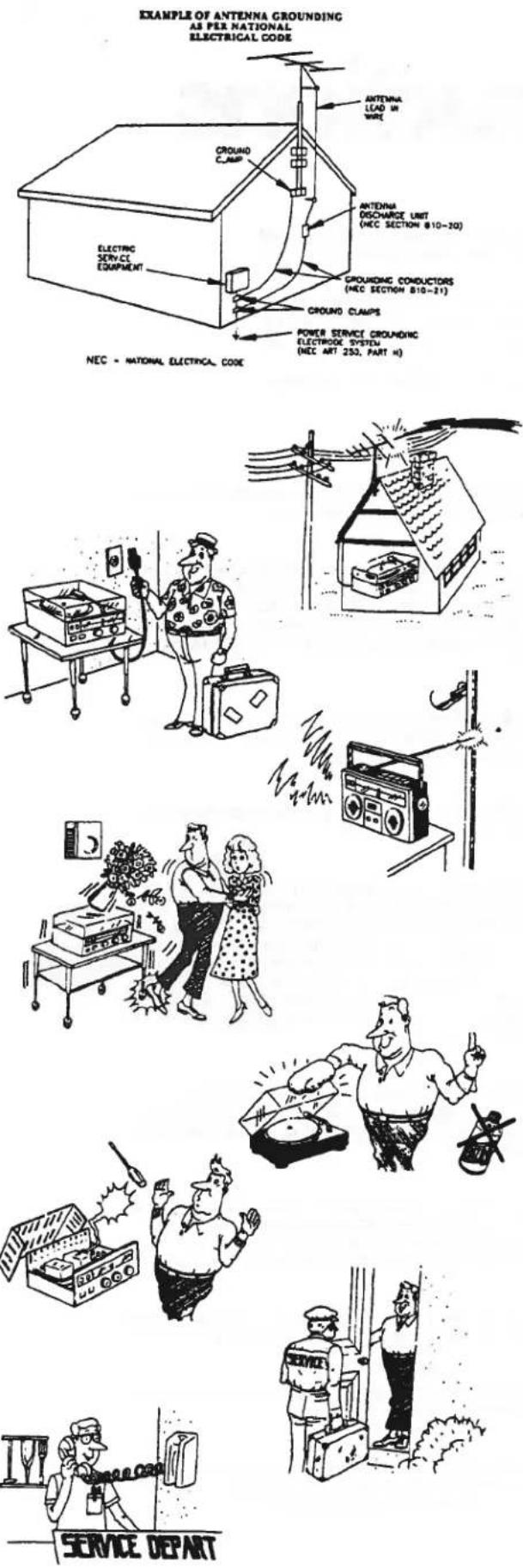
- If an outside antenna is connected to the equipment, be sure the antenna system is grounded so as to provide some protection against voltage surges and built up static charges. Section 810 of the National Electrical Code, ANSI/NFPA No. 70-1984 provides information with respect to proper grounding of the mast and supporting structure, grounding of the lead-in wire to an antenna discharge unit, size of grounding conductors, location of antenna discharge unit, connection to grounding electrodes, and requirements for the grounding electrode.
a. Use NO. 10 AWG (5.3 mm²) copper, NO. 8 AWG (8.4 mm²) aluminum NO. 17 AWG (1.0 mm²) copper-clad steel or bronze wire, or larger, as a ground wire.
b. Secure antenna lead-in and ground wires to house with stand-off insulators spaced from 4 feet (1.22 m) to 6 feet (1.83 m) apart.
c. Mount antenna discharge unit as close as possible to where lead-in enters house.
d. Use jumper wire not smaller than NO. 6 AWG (1.33 mm²) copper, or the equivalent, when a separate antenna grounding electrode is used. See NEC Section 810-21 (J)
-
An outside antenna system should not be located near overhead power lines or electric light or power circuits, or where an accident may allow the antenna system to touch power lines or circuits. When installing an outside antenna system, take every precaution to prevent the possibility of touching a power line or circuits as such contact can be fatal.
-
For added protection before and during a lightning storm, or when equipment is to be left unattended and not used for a long period of time, unplug the equipment from the wall outlet and disconnect the antenna. This will prevent damage to equipment that might be caused by power line surges or by lightning attracted to the antenna.
-
If an indoor antenna is used (either built-in the set or installed separately), never allow any part of the antenna to touch the metal parts of other electrical appliances such as a lamp, TV set, etc.
-
When you want to use the unit with a cart or stand, please consult with your sales person about the proper cart or stand recommended by the manufacturer. To use the unit on an unstable cart or stand may result in an injury to the person, damage to the unit, or other dangerous conditions.
-
Unplug the unit from the wall outlet before cleaning. Never use benzine, thinner or other solvents for cleaning. Use only a soft damp cloth.
-
Please take care that objects will not fall into the unit and liquids are not spilled through the openings into the unit, to prevent possible shock or fire hazard.
-
Unplug the unit from the wall outlet, and refer servicing to qualified service personnel under the following conditions.
a. If the power cord or plug is damaged.
b. If any object or liquid has entered the equipment.
c. If the unit has been exposed to rain.
d. If the unit does not appear to operate normally or exhibits a marked change in performance.
e. If the unit has been dropped or the case damaged.
Do not attempt to service the equipment except as described in the owner's manual. All other servicing may require extensive work by a qualified technician.
- Upon completion of any servicing or repairs, request the service shop's assurance that only Factory Authorized Replacement Parts with the same characteristics as the original parts have been used, and that routine safety checks have been performed to guarantee that the equipment is in safe operating condition. REPLACEMENT WITH UNAUTHORIZED PARTS MAY RESULT IN FIRE, ELECTRIC SHOCK, OR OTHER HAZARDS.
LAGRING AV STATIONER I SNABBVALSMINNET
4. NAD LINK (ENTRADA/SAIDA DA LIGACAO NAD)
O ligador de ENTRADA da ligação NAD no Modelo 412 permitte que o sintonizador funciona atraves dos sinais de controlo exteriores transmitidos de outras modelos de controlo remoto NAD que se caracterize por NADLink, por exemplo o reproduidor de CD 502. Sera necessário umsysteme de controlo remoto como acessario.