C730 - Audio Receiver NAD - Free user manual and instructions
Find the device manual for free C730 NAD in PDF.
User questions about C730 NAD
0 question about this device. Answer the ones you know or ask your own.
Ask a new question about this device
Download the instructions for your Audio Receiver in PDF format for free! Find your manual C730 - NAD and take your electronic device back in hand. On this page are published all the documents necessary for the use of your device. C730 by NAD.
USER MANUAL C730 NAD
Stereo AM/FM Receiver
GB Owner's Manual
F Manuel d'Installation
D Bedienungsanleitung
E Manual del Nombre
Manuale delle Istruzioni
P Manual do Propietario
S Bruksanvisning
IMPORTANT SAFETY INSTRUCTIONS

CAUTION
RISK OF ELECTRIC
SHOCK DO NOT OPEN
ATTENTION:
RISQUE DE CHOC ELECTRIQUE
NE PAS OUVRIR

CAUTION: TO REDUCE THE RISK OF ELECTRIC
SHOCK, DO NOT REMOVE COVER (OR BACK). NO
USER SERVICEABLE PARTS INSIDE. REFER SERVICING
TO QUALIFIED SERVICE PERSONNEL.
Warning: To reduce the risk of fire or electric shock, do not expose this unit to rain or moisture.
The lightning flash with an arrowhead symbol within an equilateral triangle, is intended to alert the user to the presence of uninsulated "dangerous voltage" within the product's enclosure that may be of sufficient magnitude to constitute a risk of electric shock to persons.
The exclamation point within an equilateral triangle is intended to alert the user to the presence of important operating and maintenance (servicing) instructions in the literature accompanying the product.

Do not place this unit on an unstable cart, stand or tripod, bracket or table. The unit may fall, causing serious injury to a child or adult and serious damage to the unit. Use only with a cart, stand, tripod, bracket or table recommended by the manufacturer or sold with the unit. Any mounting of the device on a wall or ceiling should follow the manufacturer's instructions and should use a mounting accessory recommended by the manufacturer.
An appliance and cart combination should be moved with care.
Quick stops, excessive force and uneven surfaces may cause the appliance and cart combination to overturn.
Read and follow all the safety and operating instructions before connecting or using this unit. Retain this notice and the owner's manual for future reference.
All warnings on the unit and in its operating instructions should be adhered to.
Do not use this unit near water; for example, near a bath tub, washbowl, kitchen sink, laundry tub, in a wet basement or near a swimming pool.
The unit should be installed so that its location or position does not interfere with its proper ventilation. For example, it should not be situated on a bed, sofa, rug or similar surface that may block the ventilation openings; or placed in a built-in installation, such as a bookcase or cabinet, that may impede the flow of air through its ventilation openings.
The unit should be situated from heat sources such as radiators, heat registers, stoves or other devices (including amplifiers) that produce heat.
The unit should be connected to a power supply outlet only of the voltage and frequency marked on its rear panel.
The power supply cord should be routed so that it is not likely to be walked on or pinched, especially near the plug, convenience receptacles, or where the cord exits from the unit.
Unplug the unit from the wall outlet before cleaning. Never use benzine, thinner or other solvents for cleaning. Use only a soft damp cloth.
The power supply cord of the unit should be unplugged from the wall outlet when it is to be unused for a long period of time.
Care should be taken so that objects do not fall, and liquids are not spilled into the enclosure through any openings.
This unit should be serviced by qualified service personnel when:
A. The power cord or the plug has been damaged; or
B. Objects have fallen, or liquid has been spilled into the unit; or
C. The unit has been exposed to rain or liquids of any kind; or
D. The unit does not appear to operate normally or exhibits a marked change in performance; or
E. The device has been dropped or the enclosure damaged.
DO NOT ATTEMPT SERVICING OF THIS UNIT YOURSELF. REFER SERVICING TO QUALIFIED SERVICE PERSONNEL
Upon completion of any servicing or repairs, request the service shop's assurance that only Factory Authorized Replacement Parts with the same characteristics as the original parts have been used, and that the routine safety checks have been performed to guarantee that the equipment is in safe operating condition. REPLACEMENT WITH UNAUTHORIZED PARTS MAY RESULT IN FIRE, ELECTRIC SHOCK OR OTHER HAZARDS.
ATTENTION
POUR ÉVITER LES CHOC ÉLECTRIQUES, INTRODUIRE LA LAME LA PLUS LARGE DE LA FICHE DANS LA BORNE CORRESPONDANTE DE LA PRISE ET POUSSER JUSQU'AU FOND.
CAUTION
TO PREVENT ELECTRIC SHOCK, MATCH WIDE BLADE OF
PLUG TO WIDE SLOT FULLY INSERT.
If an indoor antenna is used (either built into the set or installed separately), never allow any part of the antenna to touch the metal parts of other electrical appliances such as a lamp, TV set etc.
CAUTION
POWER LINES
Any outdoor antenna must be located away from all power lines.
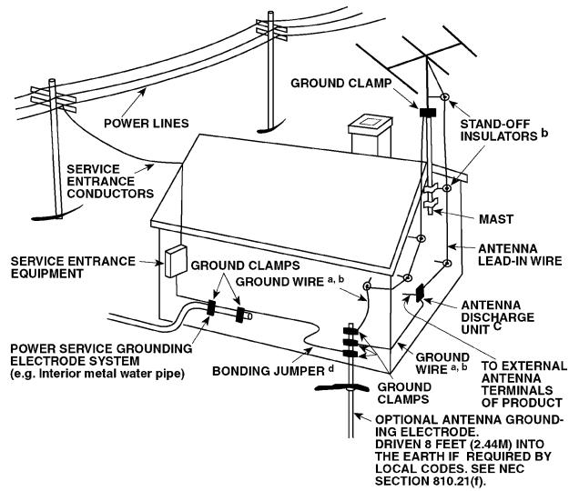
OUTDOOR ANTENNA GROUNDING
If an outside antenna is connected to your tuner or tuner-preamplifier, be sure the antenna system is grounded so as to provide some protection against voltage surges and built-up static charges. Article 810 of the National Electrical Code, ANSI/NFPA No. 70-1984, provides information with respect to proper grounding of the mast and supporting structure, grounding of the lead-in wire to an antenna discharge unit, size of grounding conductors, location of antenna discharge unit, connection to grounding electrodes and requirements for the grounding electrode.
a. Use No. 10 AWG (5.3mm2) copper, No. 8 AWG (8.4mm2) aluminium, No. 17 AWG (1.0mm2) copper-clad steel or bronze wire, or larger, as a ground wire.
b. Secure antenna lead-in and ground wires to house with stand-off insulators spaced from 4-6 feet (1.22 - 1.83 m) apart.
c. Mount antenna discharge unit as close as possible to where lead-in enters house.
d. Use jumper wire not smaller than No.6 AWG (13.3mm2) copper, or the equivalent, when a separate antenna-grounding electrode is used. See NEC Section 810-21 (j).
EXAMPLE OF ANTENNA GROUNDING AS PER NATIONAL ELECTRICAL
CODE INSTRUCTIONS CONTAINED IN ARTICLE 810 - RADIO AND TELEVISION EQUIPMENT.
NOTE TO CATV SYSTEM INSTALLER: This reminder is provided to call the CATV system installer's attention to Article 820-40 of the National Electrical Code that provides guidelines for proper grounding and, in particular, specifies that the ground cable ground shall be connected to the grounding system of the building, as close to the point of cable entry as practical.
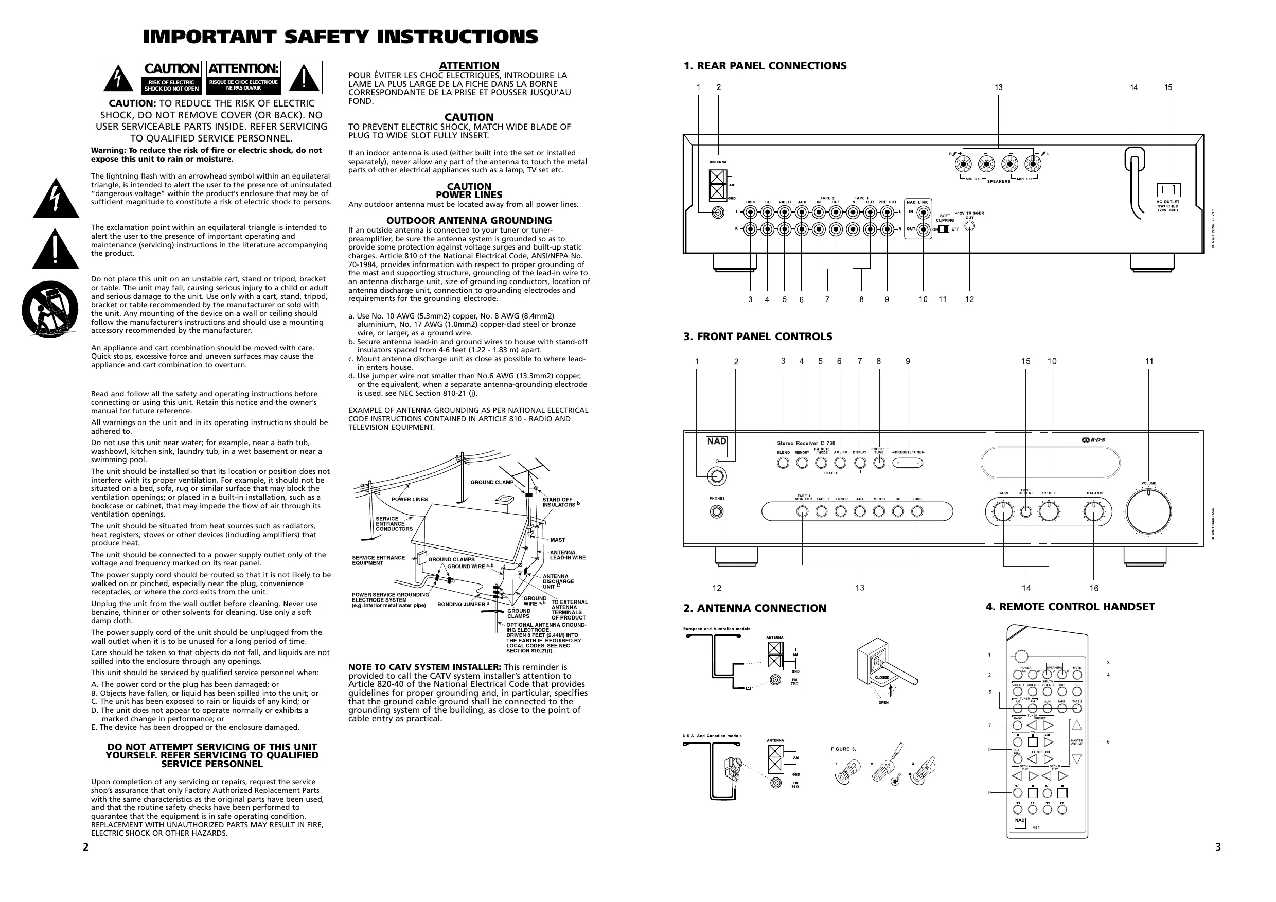
1. REAR PANEL CONNECTIONS
3. FRONT PANEL CONTROLS
2. ANTENNA CONNECTION
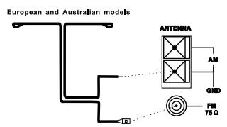
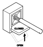
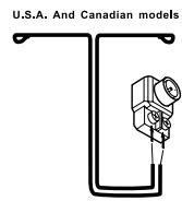
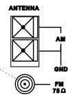

FIGURE 3.
4. REMOTE CONTROL HANDSET
NAD C730 Stereo AM/FM Receiver
QUICK START
- Connect the speakers to the Speaker terminals and sources to the relevant input sockets on the rear.
- Plug in the AC power cord.
- Press the POWER button to turn on the NAD C730.
- Press the required input selector.
- For radio listening, connect AM and FM antenna.
- Press the AM/FM button to select AM or FM reception.
- Press Preset/Tune button so that "PRESET" isn't lit in display; the tuner is now in Tune mode.
- Use Preset/Tune or to select a station.
NOTES ON INSTALLATION
Your NAD C730 should be placed on a firm, level surface. Avoid placing the unit in direct sunlight or near sources of heat and damp. Allow adequate ventilation. Do not place the unit on a soft surface like a carpet. Do not place or it in an enclosed position such a bookcase or cabinet that may impede the air-flow through the ventilation slots. Make sure the unit is switched off before making any connections.
The RCA sockets on your NAD C730 are colour coded for convenience. Red and white are Right and Left audio respectively, and yellow for NAD Link. Use high quality leads and sockets for optimum performance and reliability. Ensure that leads and sockets are not damaged in any way and all sockets are firmly pushed home.
For best performance, use quality speaker leads of 16 gauge (1.5mm) thickness or more. If the unit is not going to be used for some time, disconnect the plug from the AC socket.
Should water get into your NAD C730, shut off the power to the unit and remove the plug from the AC socket. Have the unit inspected by a qualified service technician before attempting to use it again. Do not remove the cover, there are no user-serviceable parts inside. Use a dry soft cloth to clean the unit. If necessary, lightly dampen the cloth with soapy water. Do not use solutions containing benzol or other volatile agents.
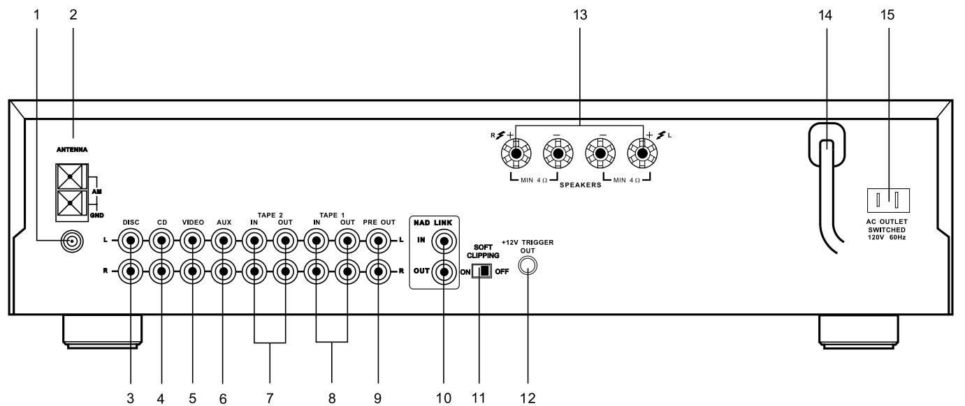
REAR PANEL CONNECTIONS (FIG 1)
1. FM ANTENNA
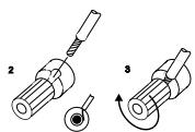
A ribbon wire FM antenna is included and should be connected to the FM connector at the rear of the unit using the supplied "balun" adapter (see fig 2). The ribbon aerial should be mounted on a vertical surface and placed so that it forms a "T".
Experiment with placement of the antenna to find the position that gives the best signal strength and lowest background noise. An inadequate FM signal normally results in high levels of hiss, especially in stereo, and interference from external electrical sources. In areas of poor FM reception, the tuner section's performance can be improved by using an externally mounted FM antenna. A qualified aerial installer will be able to advise and fit a recommended aerial for your reception conditions.
2. AM ANTENNA
An AM loop antenna is supplied with the NAD C730 and is required for AM reception. To connect the AM antenna, first press the keys on the Antenna terminals downwards. Insert the bare antenna wires into the two terminal holes and push the connector keys upwards again to secure the connection (see fig 2).
Test various positions for the antenna but always ensure the loop is placed vertically for best reception. Placing the antenna close to large metal items such as metal shelves or radiators may interfere with reception.
3. DISC INPUT
Input for additional line level input signals such as CD, Mini Disc player or the output signal from a step-up amplifier for a turntable. Use a twin RCA-to-RCA lead to connect the auxiliary unit's left and right "Audio Outputs" to this input.
4. CD INPUT
Input for a CD or other line-level signal source. Use a twin RCA to RCA lead to connect the CD player's left and right "Audio Outputs" to this input. The NAD C730 only accepts analogue signals from your CD player.
5.VIDEO INPUT
Input for the audio signal from a stereo VCR (or stereo TV/Satellite/Cable receiver) or other line-level audio source. Using twin RCA-to-RCA leads, connect to the left and right "Audio Out" of the unit to these inputs. Note: These are audio inputs only.
6. AUX INPUT
Input for additional line level input signals such as another CD player. Use a twin RCA-to-RCA lead to connect the auxiliary unit's left and right "Audio Outputs" to this input.
7. TAPE 2 IN, OUT
Connections for analogue recording and playback to an audio tape recorder of any type. Using twin RCA-to-RCA leads, connect to the left and right "Audio Output" of the tape machine to the TAPE 2 IN sockets for playback. Connect the left and right "Audio Input" of the tape machine to the TAPE 2 OUT sockets for recording.
8. TAPE 1 IN, OUT
Connections for analogue recording and playback to a secondary audio tape recorder of any type. Using twin RCA-to-RCA leads, connect to the left and right "Audio Output" of the tape machine to the TAPE 1 IN sockets for playback and tape monitoring. Connect the left and right "Audio Input" of the tape machine to the TAPE 1 OUT sockets for recording.
9. PRE OUT
The NAD C730 allows for the connection of a different or additional power amplifier. If you are using an external stereo power amplifier, use a twin RCA-to-RCA lead to connect to the left and right "Audio Input" of the Power amp to the PRE OUT 1 sockets.
NOTES: Always turn the C730 and associated external power amplifiers off before connecting or disconnecting anything to the PRE-OUT sockets.
The PRE-OUT output signal will be affected by the NAD C730's volume and tone control settings.
10. NAD-LINK IN, OUT
The NAD-Link connector is used to pass commands from other units fitted with NAD-Link connectors. This allows centralised control of a complete system, and also allows some of the basic functions of other NAD components (such as a CD player or cassette-deck) also equipped with NAD-Link to be controlled with the amplifier's remote control. To function with such other units, connect the G730's NAD-Link Out to the NAD-Link In on the other unit. NAD-Link connectors can be daisy-chained, IN to OUT, so that a whole system can be controlled from the remote control facilities of one unit.
NOTES: It is advisable not to connect NAD-Link if these units that have their own built-in remote control command receiver and are positioned together, in direct view from the remote control handset. If you are unsure, try operating the products without NAD-Link first; If the unit responds to the remote control command, it will not be necessary to connect NAD-Link.
Never loop the last unit back to the first NAD unit in the NAD-Link chain. Unplug all units from the mains before connecting or disconnecting NAD-Link.
11. SOFT CLIPPING™
When an amplifier is driven beyond its specified power output, a hard, distorted sound can be heard on very loud sounds. This is caused by the amplifier cutting off or "hard clipping" the peaks of sound that it was not designed to reproduce. The NAD Soft Clipping™ circuit gently limits the output of the system to minimise audible distortion if the amplifier is overdriven.
If your listening involves moderate power levels you may leave the Soft Clipping™ switch to Off. If you are likely to play at high levels, that could stretch the amplifier's power capability, then switch Soft Clip On.
12. 12V TRIGGER OUT
This output allows to remotely switch on or off ancillary equipment such as a tuner, power amplifier, etc. which are also equipped with a 12V trigger input. This can also be an AC outlet power strip equipped with a 12V trigger input. The 12V trigger output is activated whenever the unit is in switched to normal operational mode from Stand-by or Off.
For switching Stand-by/Power On of an external component through the C730, connect the 12V-trigger output of the C730 to the remote component's DC input jack. The plug required is a standard 3.5mm Mini-Jack plug ("mono"): The tip is the live or + connection, the shaft of the input jack is the 12V-trigger - or ground connection.
NOTES: Check the specifications of the Trigger input terminal on the other components to ensure these are compatible with the C730's 12V-trigger output. NAD components equipped with 12V input triggers are fully compatible with the C730's 12V output trigger.
The C730's 12V-trigger output voltage is 12V DC. The total maximum current must not exceed 200mA . Typically, NAD 12V input triggers draw less than 10mA of current. Before making any connections to any 12V trigger input or output, make sure all components are disconnected from the AC mains.
Failure to observe the above may result in damage to the C730 or any ancillary components attached to it. If in doubt over the connections, installation and operation of the 12V trigger output consult your NAD dealer.
13. SPEAKERS
Connect the right speaker to the terminals market “R +” and “R-” ensuring that the “R+” is connected to the “+” terminal on your loudspeaker and the “R-” is connected to the loudspeaker’s “-” terminal. Connect the terminals marked “L+” and “L-” to the left speaker in the same way.
Always use heavy duty (16 gauge; 1.5mm , or thicker) stranded wire to connect loudspeakers to your NAD C730. The high-current binding post terminals can be used as a screw terminal for cables terminating in spade or pin sockets or for cables with bare wire ends.
BARE WIRES AND PIN CONNECTORS
Bare wires and pin sockets should be inserted into the hole in the shaft of the terminal. Unscrew the speaker terminal's plastic bushing until the hole in the screw shaft is revealed. Insert the pin or bare cable end into the hole and secure the cable by tightening down the terminal's bushing.
Ensure bare wire from the speaker cables does not touch the back panel or another socket. Ensure that there is only 1/2 (1cm) of bare cable or pin and no loose strands of speakers wire.
NOTE: Make sure the speaker impedance is 4 ohms or more when connecting only one pair of speakers; make sure the speaker impedance for all speakers is over 8 ohms when connecting two sets of speakers.
14. AC LINE CORD
Plug the AC power cord into a live AC wall socket. Make sure all connections have been made before connecting to mains.
15. SWITCHED AC OUTLET
The AC power cord of another component may be plugged into this accessory outlet. Components plugged into this outlet will be switched On and Off by the POWER button on the front panel or by the ON and STAND-BY button on the remote control handset.
NOTE: The total power consumption of any components connected to the AC outlets may not exceed 100 Watts.
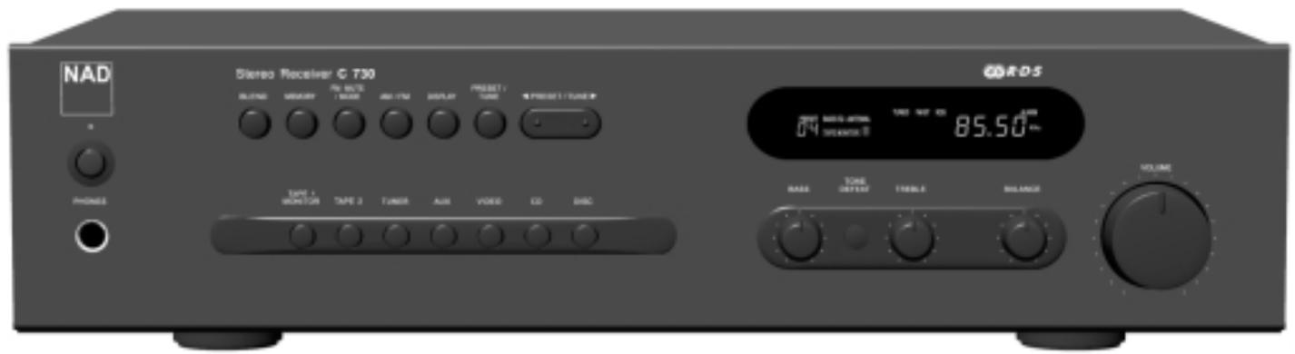
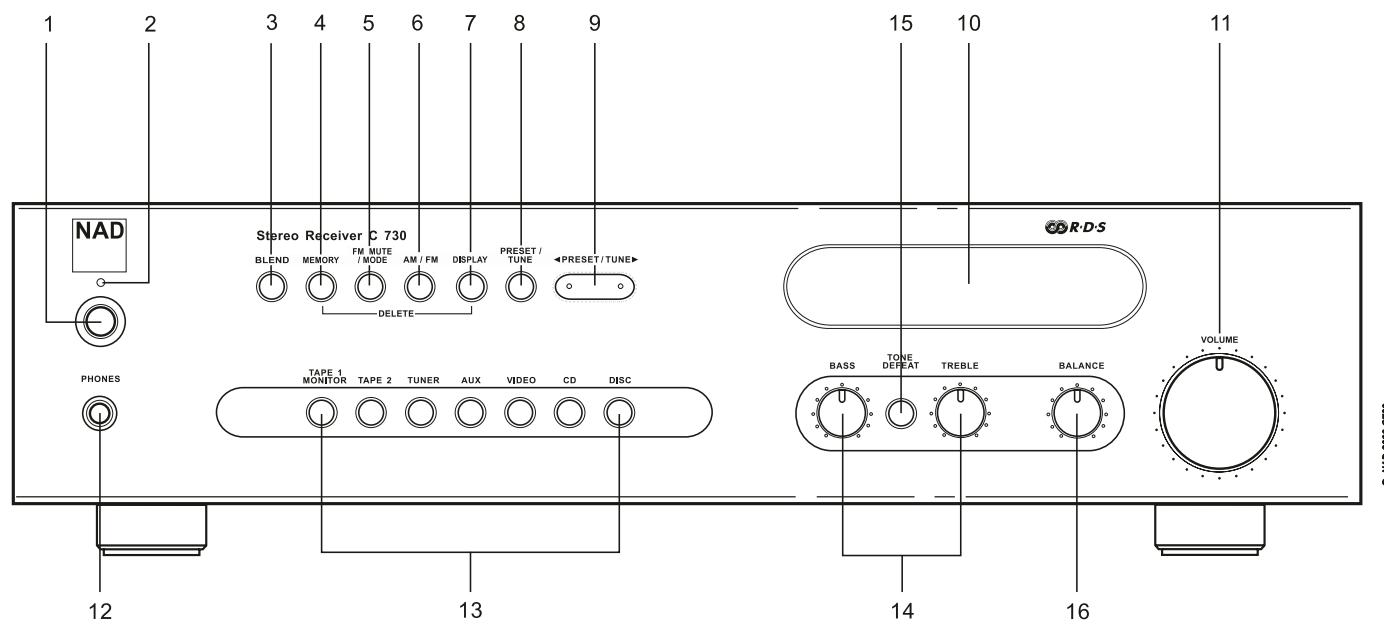
FRONT PANEL CONTROLS (FIG 3)
1. POWER ON/OFF
Press the POWER button to switch the receiver On. The Stand-by indicator (No. 2) over the power button will light up amber and after a short pause will turn to green to indicate the receiver is now ready for normal operation.
Pressing the POWER switch again will turn the unit OFF completely, it will not respond to the remote control.
REMOTE CONTROL
STANDBY/ON button (No.1)
When the receiver is switched On, pressing the green On/Off button on the remote handset will put the receiver into Standby mode and the Power indicator will turn amber. The amber Power indicator shows that power is being supplied, but the system is currently in the Standby Mode. Press again to switch the receiver On from Stand-by mode.
ON and OFF buttons (No.2)
Besides the On/Off toggle function of the green button (No. 1), the NAD G730 remote also has a separate On and Off button. This can be particularly useful to keep components within a system "in-sync": This way all components will switch to stand-by when Off is pressed or switch to operating mode when On is pressed, instead of some components switching On when the receiver is switched to Stand-by. (Note that the other components have to be capable of responding to the separate On and Off commands as well).
Press the ON button to switch the unit from Stand-by to the operating mode; The Stand-by indicator (Fig. 2; No. 2) will turn from amber to green to indicate the receiver is ready for use. Press the OFF button to switch the unit to the Stand-by mode: The Stand-by indicator will light up amber.
NOTE: In Stand-by mode the C730 uses very little power. However, it is recommended that you switch the unit totally off if it is not going to be used for more than a couple of days. Switch off completely by pressing the POWER button on the front panel (No. 1), all lights will extinguish.
2. STAND-BY INDICATOR
This indicator lights up green during normal operation. In Standby mode the indicator will light up amber. Refer to section 1 in this chapter for more information. The indicator will blink when the receiver receives a remote control command from the supplied handset.
If the receiver goes into "protection" mode the Led will flash continuously at a rate of two flashes per second. This can occur if there is a short circuit in the speaker wiring. Switch the unit off totally using the Power button on the front panel (No 1) and check all the cables and connections both at the receiver side and at the loudspeakers side. Once all the connections are restored correctly, switch the Power button (No 1) on, with the volume initially set low and then resume normal operation. If the problem persists, switch of the power completely and consult your dealer.
3. BLEND
Weak or remote stereo radio stations are sometimes received with noise and hiss as the antenna signal is too weak. By switching the tuner to mono will reduce the amount of noise and hiss but at the expense of any stereo information. The NAD Blend feature will allow you to reduce the amount noise and hiss but still retain some level of stereo separation, instead of mono. The Blend button toggles between engaging or disengaging the Blend feature; when engaged, "BLEND" lights up in the display.
NOTE: The "Blend" status can be stored for individual presets. Refer to the separate chapter "Storing, Recalling and Labelling Presets" for more information.
4. MEMORY
The Memory is used to store stations into the Preset Memory bank and to store user defined names for non-RDS Preset stations. When Memory is pressed during normal operation, the Preset number and the red "MEMORY" indicator will flash in the Display Panel. If no other buttons are pressed within 12 seconds, the receiver will revert to its previous state. Refer to the separate chapter "Storing, Recalling and Labelling Presets" for more information.
5. FM MUTE/MODE
This button combines two functions; it switches the receiver's tuning section from Stereo to Mono and disengages the muting circuitry at the same time. The muting circuit will mute the tune in between radio stations when searching or tuning. This way the tuning noise is avoided.
The muted circuit however may suppress very weak radio station signals. If a weak station is in stereo it will have a high level of background hiss. Switching to Mono Mode and disengaging the muted circuit by depressing the FM MUTE/MODE button will allow the station to be heard and will cancel most or all of this background noise.
In normal operation the mute circuit is engaged, the display indicates "FM MUTE". Press the FM Mute/Mode button to disengage the muting circuit and switch from stereo to mono reception. "FM MUTE" in the display will extinguish. Press the FM Mute/Mode switch again to return to Auto Stereo FM operation.
NOTE: The "FM Mute/Mode" status can be stored for individual presets. Refer to the separate chapter "Storing, Recalling and Labelling Presets" for more information.
6. AM/FM
The AM/FM button switches the tuner from the AM band to the FM band and vice-versa. The Display Panel shows the frequency of the tuned station and which band is selected. The FM tuning is in 0.05 MHz increments, AM tuning is in 9kHz or 10kHz increments, depending on the version.
7. DISPLAY
With stations carrying RDS information, The Display button scrolls between three different display modes, each successive push of the button engages the next one of the three modes:
a) In the default mode, the station's RDS name is displayed, Program Service (PS; normally the station's calling letters, BBC R3, for instance).
b) From the default mode, press the button once to view Radio Text (RT). This can be additional information such as the presenter's or program's name; what song is playing, etc. This text scrolls continuously over the 8 alphanumeric display segments.
c) Press the button from the display RT mode to display the station frequency. Press again to return to the default mode (a).
When tuned to a non-RDS station
The Display button toggles the display to show either the station frequency or user entered station name. If no user name was entered the display will indicate "NO RDS".
The Display button is also used to label non-RDS stations with a name. Refer to the separate chapter "Storing, Recalling and Labelling Presets" for more information.
8. PRESET/TUNE
The Preset/Tune button toggles between two different modes:
a) Preset mode: In this mode you can use the Tune/Preset or buttons (No. 9) to select a Preset. When Preset Mode is selected "PRESET" will scroll once through the display and the PRESET indicator lights up in the display.
b) Tune mode: By pressing the Preset/Tune button (No. 9) or you can engage automatic or manual tuning respectively down or up the frequency band. When Tune mode is selected, "TUNE" will scroll through the display once.
9. PRESET/TUNE AND
The function of these buttons depends on the tuning mode selected with the Preset/Tune button (No. 8). The Preset/Tune button toggles between the two operation modes:
a) Preset mode (indicated in the display area): Press the (down) button to scroll to a lower number Preset; press the (up) button to scroll to a higher Preset number. This is a "wrap-around" function, so that going from the highest number Preset, the tuner will go to the lowest Preset number or vice-versa when tuning either up or down.
b) Tune mode: Press the (down) or (up) button for more than 1 second to engage automatic tuning respectively up or down the frequency band. The tuner will search automatically for the first reasonably strong radio station, where it will stop. Press the Down/Up button again for 1 second to start searching again.
By briefly tapping the (down) or (up) buttons you can engage manual tuning respectively up or down the frequency band for precise tuning to a specific frequency. With each successive tap of the keys, the tuner will take 0.05MHz steps on FM so you can accurately tune into the desired frequency. For AM the tuning steps are set at 10kHz (120V version) or 9kHz (230V version).
This tuning mode can also be useful when trying to receive a radio station, which is too weak for the auto search mode. When tuned accurately to a station, "TUNED" will light up in the display. The mating circuit, however may suppress very weak radio station signals. If such a very weak station is in stereo it will have a high level of background hiss. Switching to Mono Mode and disengaging the mating circuit by depressing the FM MUTE/MODE button (No. 5) will allow the station to be heard and will cancel most or all of this background noise.
NOTES: Automatic tuning is available on both FM and AM.
Even if the C730 is in Tune Mode, the remote control's Preset Up and Down buttons will only change presets.
The Preset/Tune and buttons are also used in conjunction with the Memory (No. 4) and Display (No. 7) buttons to add and memorise user defined names to Presets. Refer to the separate chapter "Storing, Recalling and Labelling Presets" for more information.
10. DISPLAY AREA
The display area gives all vital information on the status of the receiver. Displayed are:
- Which input is selected
Volume MUTE On - Tape Monitor engaged
- Tone Defeat On
- Band and frequency of current station, RDS PS (station name), or RDS Radio Text. The latter two only if RDS is available; select using the Display button (No. 7).
- If an FM Stereo broadcast is received.
- If the FM station also broadcasts RDS.
- If "Memory" has been engaged
- Preset number if the current station is stored in the tuner's memory bank.
- If Blend and FM Mute/Mode are switched On.
- Radio Signal Strength. The bars just below "ANTENNA" indicate the radio station's signal strength. The more bars are lit, the stronger the station.
NOTE: The infrared sensor, which receives commands from a remote control (not supplied), is located on the left side of the display window. There must be a clear line-of-sight path from the remote control to this window; if that path is obstructed, the remote control may not work.
11. VOLUME
The VOLUME control adjusts the overall loudness of the signals being fed to the loudspeakers. It is motor driven and can be adjusted from the remote control handset. The VOLUME control does not affect recordings made using the Tape outputs but will affect the signal going to the Pre-amp output (Pre Out).
On the remote control handset, press the MUTE Button to temporarily switch off the sound to the speakers and headphones. Mute mode is indicated by "MUTE" flashing in red in the display area. Press MUTE again to restore sound. Mute does not affect recordings made using the Tape outputs but will affect the signal going to the Pre-amp output (Pre Out).
12. HEADPHONE SOCKET
A 1/4" stereo jack socket is supplied for headphone listening and will work with conventional headphones of any impedance. Inserting a headphone jack into this socket automatically switches off the loudspeakers. The volume, tone and balance controls are operative for headphone listening. Use a suitable adapter to connect headphones with other types of sockets, such as 3.5mm stereo "personal stereo" jack plugs.
13. INPUT SELECTORS
These buttons select the active input to the NAD C730 and the signal sent to the loudspeakers, the Tape outputs and the PRE OUT sockets. The buttons on the remote control handset duplicate these buttons, with the exception of the tuner input; see below. The display indicates which input has been selected.
DISC Selects a line-level source connected to the DISC sockets as the active input.
CD Selects the CD (or other line-level source) connected to the CD sockets, as the active input.
VIDEO Selects the VCR (or stereo TV/Satellite/Cable receiver) connected to the VIDEO sockets, as the active input.
AUX Selects a line-level source connected to the AUX sockets, as the active input.
TUNER Selects the tuner as the active input. The receiver will return to the last selected preset or frequency. The remote control handset has separate buttons for AM and FM; pressing either one will select the tuner as the active input and revert to the last station tuned to on respectively the AM or FM band.
TAPE 2 Selects Tape 2 as the active input.
TAPE 1 Monitor Selects the output from a tape recorder when playing back tapes or monitoring recordings being made through the Tape 1sockets. Press the Tape 1 button once to select it and again to return to the normal input selection.
Tape 1 is a tape Monitor function which does not override the current input selection. For example, if the CD is the active input when TAPE 1 is selected, then the CD signal will continue to be selected and sent to both the TAPE 1, and TAPE 2 OUTPUT sockets, but it is the sound from recorder connected to Tape 1 that will be heard on the loudspeakers. When Tape 1 Monitor is selected, "TAPE 1" is indicated in the alphanumeric section of the display for 3 seconds before it defaults to indicating the active input again. The red box next to the preset number section in the display indicating "TAPE MONITOR" will remain lit until Tape 1 is disengaged again.
NOTE: The remote control handset with the C730 supplied is of a universal NAD type, designed to operate several NAD models. Some buttons on this handset are inoperative as the functions aren't supported by the C730. The Video 2, Video 3 input selector buttons, tuner Bank button, speakers A and Speakers B buttons on the remote control handset are inoperative in the case of the C730.
NOTE: Make certain that the volume control is turned to minimum (fully anti-clockwise) before connecting or disconnecting headphones. Listening at high levels can damage your hearing.
14. BASS & TREBLE CONTROLS
The NAD C730 is fitted with BASS and TREBLE tone controls to adjust the tonal balance of your system.
The 12 o'clock position is "flat" with no boost or cut and a detent indicates this position. Rotate the control clockwise to increase the amount of Bass or Treble. Rotate the control anti-clockwise to decrease the amount of Bass or Treble. The Tone controls do not affect recordings made using the Tape outputs but will affect the signal going to the Pre-amp output (Pre Out).
15. TONE DEFEAT
The TONE DEFEAT switch by-passes the tone control section of the NAD G730. If the Tone Controls are not normally used and left in the 12 o'clock position, then it is advisable to switch out the Tone Control section altogether by using this switch. In the "out" position, the Tone Control circuits are active, pushing the TONE DEFEAT switch "in" bypasses the Tone Control section.
16. BALANCE
The BALANCE control adjusts the relative levels of the left and right speakers. The 12 o'clock position provides equal level to the left and right channels. A detent indicates this position.
Rotating the control clockwise moves the balance towards the right. Rotating the control anti-clockwise moves the balance to the left. The BALANCE control does not affect recordings made using the Tape outputs but will affect the signal going to the Pre-amp output (Pre Out).
STORING, RECALLING AND LABELLING PRES
Up to 30 presets in total can be stored in the C730's memory bank; these can be any mix of either AM or FM stations. When scrolling through the presets, empty preset places will be skipped; it is thus possible to go from preset No. 4 to No. 7 without having seen No. 5 and 6. With the presets you can also store whether you want Blend (No. 3) and FM Mute/Mode (No. 5) to be activated as well every time you recall the preset.
TO STORE A PRESET
- Tune to the radio station you wish to enter into a Preset (refer to this chapter's section 9). If the station is transmitting RDS information, the RDS indicator will light up and station initials or name will be shown in the Display Panel. If a non-RDS station is found, then just the frequency will be shown.
- Select Blend (No. 3) or FM Mute/Mode (No. 5) if desired.
- To store that station as a Preset, press Memory (No. 4). The Preset number and the red "MEMORY" indicator are flashing in the Display Panel. The lowest available empty preset number will be shown. If no other buttons are pressed within 8 seconds, the tuner will revert to its previous state.
- Press Memory again to store the preset. If you wish to assign a different preset number, press either the Preset/Tune or button to select the desired preset number. You can overwrite an existing preset. If the preset number already has been assigned, "MEMORY" will stop blinking, but the preset will continue to blink. When you have selected the desired preset number, press Memory again to store the station.
NOTES: You can enter a new station into an unused Preset or over-write an existing programmed Memory Preset. By doing this you will replace all the data previously held on that Preset number.
When Memory is pressed during normal operation, the Preset number and the red "MEMORY" indicator will flash in the Display Panel. If no other buttons are pressed within 8 seconds, the tuner will revert to its previous state. The Memory Presets have a memory back-up, so they will remain stored for several weeks even if the Tuner is switched off or unplugged from the mains supply.
RECALLING A PRESET
- To select a Preset station, check if Preset mode is engaged (the display indicates "PRESET"). If not, press the Preset/Tune Mode button (No. 8); "PRESET" will now light up in the display.
- Press either the Preset/Tune or buttons (No. 9) until the right Preset is found and shown in the Display Panel.
Any unused Presets will be skipped; this avoids having to scroll through empty presets.
DELETING A STORED PRESET
You can empty a Preset by deleting the stored information:
- Select the Preset to be emptied.
- Press and hold the Memory button (No. 4) and Display button (No.7) for two seconds. The preset number and the text "DELETE" will flash in the display.
- Press only the display button again (within default time of 8 seconds) to confirm you want to delete this preset. The text "DELETED" and "—" as the Preset number appear in the display for a couple of seconds.
LABELLING A PRESET
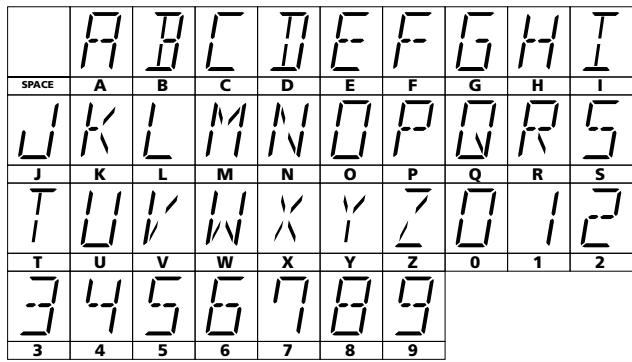
When a station is transmitting RDS information, your NAD C730 will automatically show the station initials. Although the Tuner automatically shows the frequency of any other AM or non-RDS Preset station, it also allows you to type in the station name to make it easier to identify which station is stored in the Memory Preset. To enter a name:
1) Select the Preset you want to attach a name to.
2) Press and hold the Display button (No. 7) for two seconds. The first space in the Station Data area of the Display Panel will flash.
3) Press either the Tune/Preset or (No. 9) button to scroll and select the first character (see Character list below for reference).
4) Press Display to move one place to the right to enter the next desired character.
5) Use the Tune/Preset buttons again to select the next character in the name.
6) Repeat steps 3 to 5 until name is complete or all eight places have been filled (up to 8 characters).
7) Press Memory once to finish the labelling procedure. Press Memory again to store the completed name.
There are 37 characters available including a blank space.
NOTE: This function is only available for non-RDS stations. RDS stations will always display their transmitted name and cannot be over-written.
TO MAKE A RECORDING
When any source is selected, its signal is also fed directly to any tape machine connected to the TAPE 1 or TAPE 2 OUTPUTS on the rear panel for recording.
TAPE TO TAPE COPYING
You can copy between two tape machines connected to your NAD C730. Put the source tape in the recorder connected to Tape 2 and the blank tape into the recorder connected to Tape 1. By selecting TAPE 2 Input, you can now record from Tape 2 to Tape 1 and monitor the signal coming from the original tape.
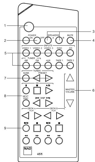
REMOTE CONTROL HANDSET (FIG 4)
The Remote Control handset handles all the key functions of the NAD C730 and has additional controls to remotely operate NAD Tuners, Cassette and CD machines. It will operate up to a distance of 16ft (5m). Alkaline batteries are recommended for maximum operating life. Two AAA (R 03) batteries should be fitted in the battery compartment at the rear of the Remote Control handset. When replacing batteries, check that they have been put in the right way round, as indicated on the base of the battery compartment. Please refer to previous sections of the manual for a full description of individual functions.
When a command from the remote control is received, the Standby/protection indicator will blink. Note that the indicator may also blink when receiving commands not necessarily for the C730 but for other components in the system.
1. STANDBY/ON BUTTON
When the amplifier is switched On, pressing the green On/Off button on the remote handset will put the NAD-370 into Standby mode and the Power indicator will turn amber. The amber Power indicator shows that power is being supplied to the NAD-370, but the system is currently in the Standby Mode. Press again to switch the amplifier On from Stand-by mode.
2. POWER ON & OFF
Besides the On/Off toggle function of the green button (No. 1), the NAD C730 remote also has a separate On and Off button. This can be particularly useful to keep components within a system "in-sync": This way all components will switch to stand-by when Off is pressed or switch to operating mode when On is pressed, instead of some components switching On when the amplifier is switched to Stand-by. (Note that the other components have to be capable of responding to the separate On and Off commands as well).
Press the ON button to switch the unit from Stand-by to the operating mode; The Stand-by indicator (Fig. 2; No. 2) will turn from amber to green and the indicator for the last selected input will blink and light up. Press the OFF button to switch the unit to the Stand-by mode: The Stand-by indicator will light up amber.
3. SPEAKERS A & B
These buttons are inoperative on the C730
4. MUTE
Press the MUTE Button (No. 4) to temporarily switch off the sound to the speakers and headphones. Mute mode is indicated by "MUTE" flashing in red in the display area. Press MUTE again to restore sound. Mute does not affect recordings made using the Tape outputs but will affect the signal going to the Pre-amp output (Pre-Out).
5. INPUTS
The input selector buttons (No. 5) perform the same functions as the buttons labelled the same on the front panel. There are a few differences and extra functions with the remote control handset however:
The TUNER AM & FM buttons select the Tuner input and respectively the AM or FM waveband. The receiver will tune to the last station selected on either AM or FM band.
NOTE: The Video 2 and Video 3 input selector buttons are inoperative.
6. MASTER VOLUME
Press the MASTER VOLUME ▲ or ▼ (No. 7) buttons to increase, respectively decrease the loudness level. Release the button when the desired level is reached. The motorised Volume Control on the front panel will indicate the level set. The Master Volume buttons do not affect recordings made using the Tape outputs but will affect the signal going to the Pre-amp output (Pre-Out).
7. TUNER CONTROL BUTTONS
PRESET or selects respectively higher or lower number station preset. The BANK button is inoperative on the C730.
8. CD PLAYER CONTROL BUTTONS
(for use with NAD CD Player).
II engages Pause
■ engages Stop
/ engages Play or toggles between Play and Pause
or engages Track skip; Press once to respectively go to the next track or to return to start of current or previous track. NEXT DISC Go to next disc (for NAD CD changers).
9. CASSETTE DECK CONTROL BUTTONS
(for use with single (DECK B) or double transport (A and B) NAD Cassette Decks).
or engages Forward Play or Reverse Play.
/ Record/Pause. Press to put cassette deck into record-pause. Press Play to start recording.
Stops Play or Recording
engages Rewind.
engages Fast Forward.
NOTES: The remote control handset supplied with the C730 is of a universal NAD type, designed to operate several NAD models. Some buttons on this handset are inoperative, as the functions aren't supported by the C730. The Video 2, Video 3 input selector buttons (inside section 5), tuner Bank button (section 7), speakers A and Speakers B buttons (section 3) on the remote control handset are inoperative in the case of the C730.
Direct sunlight or very bright ambient lighting may affect the operating range and angle for the remote control handset.
The infrared remote control command receiver, located on the far left of the display window, receives commands from the remote control. There must be a clear line-of-sight path from the remote control to this window; if that path is obstructed, the remote control may not work.
| TROUBLESHOOTING | ||
| Problem | Cause | Solution |
| NO SOUND | •Power AC lead unplugged or power not switched on •Tape 2 Monitor selected •Mute on •Rear Pre-out/Main-in amp links not fitted •Speakers not switched on | •Check if AC lead is plugged in and power switched on •De-select Tape 2 Monitor mode •Switch off Mute •Fit links •Switch Speakers A or B on |
| NO SOUND ONE CHANNEL | •Balance control not centered •Speaker not properly connected or damaged. •Input lead disconnected or damaged | •Center Balance control •Check connections and speakers •Check leads and connections |
| WEAK BASS/DIFFUSE STEREO IMAGE | •Speakers wired out of phase | •Check connections to all speakers in the system |
| REMOTE CONTROL HANDSET NOT WORKING | •Batteries flat, or incorrectly inserted •IR transmitter or receiver windows obstructed •IR receiver in direct sun or very bright ambient light | •Check or replace batteries •Remove obstruction •Place unit away from direct sun, reduce amount of ambient light |
| NO SOUND WITH TUNER | •Antenna leads incorrectly connected •Station not selected or weak signal with FM Mute on. •Internal fuse blown | •Check antenna connections to receiver •Re-tune or switch off FM Mute •Consult dealer |
| NOISE, HISS ON AM AND FM | •Weak signal | •Check station tuning. Adjust or replace antenna. |
| DISTORTION ON FM | •Multi-path signals or interference from another station | •Check station tuning. Adjust or replace antenna |
| WHISTLES OR BUZZES ON FM & AM | •Interference from other electrical sources - computers, games consoles | •Check station tuning. Switch off or move the source of the electrical noise |
| WHISTLES OR BUZZES ON AM | •Interference from fluorescent lighting or electrical motors | •Check station tuning. Adjust or replace AM antenna |
| NO RDS INFORMATION | •Station signal too weak. •Station not transmitting RDS data | •Check station tuning. Adjust or replace antenna •No remedy |
1. MARCHE/ARRET (POWER ON/OFF)
| E | F | G | H | I | |
| ESPACE | A | B | C | D | E |
| J | K | L | M | N | O |
| T | U | V | W | X | Y |
| 3 | 4 | 5 | 6 | 7 | 8 |
NAD C730 Stereo AM/FM Receiver
SCHNELLSTART
5. TASTE FM MUTE/MODE
10. NAD LINK IN, OUT
Pulsador STANDBY/ON (No. 1)
| SPACE | A | B | C | D | E | F | G | H | I |
| J | K | L | M | N | O | P | Q | R | S |
| T | |||||||||
| T | U | V | W | X | Y | Z | 0 | 1 | 2 |
| 3 | 4 | 5 | 6 | 7 | 8 | 9 |
7. TAPE 2 IN, OUT (NASTRO 2 IN, OUT)
8. TAPE 1 IN, OUT (NASTRO 1 IN, OUT)
Pulsante STANDBY/ON (No.1)
Pulsanti ON ed OFF (No. 2).
5. FM MUTE/MODE (MODO/SILENZIO FM)
| A | B | C | D | E | F | G | H | I | |
| SPACE | A | B | C | D | E | F | G | H | I |
| J | K | L | M | N | O | P | Q | R | S |
| T | U | V | W | X | Y | Z | 0 | 1 | 2 |
| 3 | 4 | 5 | 6 | 7 | 8 | 9 |
| H | B | L | U | E | F | G | H | I | |
| ESPAço | A | B | C | D | E | F | G | H | I |
| K | L | M | N | O | P | Q | R | S | |
| J | K | L | M | N | O | P | Q | R | S |
| T | L | L | L | V | V | Z | I | I | I |
| I | L | L | I | A | I | Z | I | I | I |
| T | U | V | W | X | Y | Z | 0 | 1 | 2 |
| 3 | 4 | 5 | 6 | 7 | 8 | 9 |
NAD C730 Stereo AM/FM Receiver
SNABBSTART
| H | B | L | U | E | F | G | H | I | |
| SPACE | A | B | C | D | E | F | G | H | I |
| K | L | M | N | O | P | Q | R | S | |
| J | K | L | M | N | O | P | Q | R | S |
| T | L | I | I | V | V | I | I | I | I |
| I | L | I | I | V | I | I | I | I | I |
| T | U | V | W | X | Y | Z | 0 | 1 | 2 |
| 3 | 4 | 5 | 6 | 7 | 8 | 9 | |||
| 3 | 4 | 5 | 6 | 7 | 8 | 9 |
www.NADelectronics.com