
710 - Audio Amplifier NAD - Free user manual and instructions
Find the device manual for free 710 NAD in PDF.
| Product type | Stereo audio amplifier |
| Brand | NAD |
| Model | 710 |
| Power supply | Mains: AC wall plug |
| Main functions | Integrated stereo amplifier with AM/FM tuner, tone controls (bass/treble), tone defeat, input selector (CD, Video, Aux, Tuner, Portable), tape monitor, Mono mode, dual volume control with balance, memory for 12 FM and 12 AM stations, manual search and tuning |
| Inputs | CD, Video, Aux, Tuner, Portable (3.5 mm stereo mini-jack), tape deck (Tape In) |
| Outputs | Speakers (impedance 4 Ω or higher), tape deck (Tape Out), Portable |
| Antenna connectivity | FM antenna (flat cable with balun adapter), AM antenna (wire), ground terminal |
| Maintenance and cleaning | Use a soft dry cloth or slightly dampened with soapy water. Do not use volatile solvents. |
| Safety | Ensure adequate ventilation (do not place on carpet or in confined space). Do not remove the cover. Unplug in case of humidity or prolonged non-use. |
| General information | Non-volatile memory for preset stations. Built-in thermal circuit breaker. Use quality RCA cables and speaker wire of gauge 16 or higher. |
Frequently Asked Questions - 710 NAD
User questions about 710 NAD
0 question about this device. Answer the ones you know or ask your own.
Ask a new question about this device
Download the instructions for your Audio Amplifier in PDF format for free! Find your manual 710 - NAD and take your electronic device back in hand. On this page are published all the documents necessary for the use of your device. 710 by NAD.
USER MANUAL 710 NAD
IMPORTANT SAFETY INSTRUCTIONS


CAUTION: TO REDUCE THE RISK OF ELECTRIC SHOCK, DO NOT REMOVE COVER (OR BACK) NO USER SERVICEABLE PARTS INSIDE. REFER SERVICING TO QUALIFIED SERVICE PERSONNEL.
ATTENTION: AFIN DEVITER UN CHOC ELECTRIQUE, ET LES CONSEQUENCES GRAVES QUI POURRAIENT EN RESULTER, TENTEZ PAS D'OUVRIR L'APPAREIL ET DE TOUCHER AUX COMPOSANTS INTERNES SANS LA PRESENCE D'UNE SERVICE PERSONNEL.
Warning: To reduce the risk of fire or electric shock, do not expose this unit to rain or moisture.

The lightning flash with an arrowhead symbol within an equilateral triangle is intended to alert the user to the presence of uninsulated “dangerous voltage” within the product’s enclosure that may be of sufficient magnitude to constitutet a risk of electric shock to persons.

The exclamation point within an equilateral triangle is intended to alert the user to the presence of important operating and maintenance (servicing) instructions in the literature accompanying the product.

Do not place this unit on an unstable cart, stand or tripod, bracket or table. The unit may fall, causing serious injury to a child or adult and serious damage to the unit. Use only with a cart, stand, tripod, bracket or table recommended by the manufacturer or sold with the unit. Any mounting of the device on a wall or ceiling should follow the manufacturer's instructions and should use a mounting accessory recommended by the manufacturer.
An appliance and cart combination should be moved with care. Quick stops, excessive force and uneven surfaces may cause the appliance and cart combination to overturn.
Read and follow all the safety and operating instructions before connecting or using this unit. Retain this notice and the owner's manual for future reference.
All warnings on the unit and in it's operating instructions should be adhered to.
Do not use this unit near water; for example, near a bath tub, washbowl, kitchen sink, laundry tub, in a wet basement or near a swimming pool.
The unit should be installed so that its location or position does not interfere with its proper ventilation. For example, it should not be situated on a bed, sofa, rug or similar surface that may block the ventilation openings; or placed in a built-in installation, such as a bookcase or cabinet, that may impede the flow of air through its ventilation openings.
The unit should be situated from heat sources such as radiators, heat registers, stoves or other devices (including amplifiers) that produce heat. The unit should be connected to a power supply outlet only of the voltage and frequency marked on its rear panel.
The power supply cord should be routed so that it is not likely to be walked on or pinched, especially near the plug, convenience receptacles, or where the cord exits from the unit.
Unplug the unit from the wall outlet before cleaning. Never use benzine, thinner or other solvents for cleaning. Use only a soft damp cloth.
The power supply cord of the unit should be unplugged from the wall outlet when it is to be unused for a long period of time.
Care should be taken so that objects do not fall, and liquids are not spilled into the enclosure through any openings.
This unit should be serviced by qualified service personnel when:
A. The power cord or the plug has been damaged; or
B. Objects have fallen, or liquid has been spilled into the unit; or
C. The unit has been exposed to rain or liquids of any kind; or
D. The unit does not appear to operate normally or exhibits a marked change in performance; or
E. The device has been dropped or the enclosure damaged.
Upon completion of any servicing or repairs, request the service shop's assurance that only Factory Authorized Replacement Parts with the same characteristics as the original parts have been used, and that the routine safety checks have been performed to guarantee that the equipment is in safe operating condition.
REPLACEMENT WITH UNAUTHORIZED PARTS MAY RESULT IN FIRE, ELECTRIC SHOCK OR OTHER HAZARDS.
ATTENTION
POUR EVITER LES CHOC ELECTRIQUES, INTRODUIRE LA LAME LA PLUS LARGE DE LA FICHE DANS LA BORNE CORRESPONDANTE DE LA PRISE ET POUSSER JUSQU'AU FOND.
CAUTION
TO PREVENT ELECTRIC SHOCK MATCH WIDE BLADE OF PLUG TO WIDE SLOT FULLY INSERT.
If an indoor antenna is used (either built into the set or installed separately), never allow any part of the antenna to touch the metal parts of other electrical appliances such as a lamp, TV set etc.
CAUTION POWER LINES
Any outdoor antenna must be located away from all power lines.
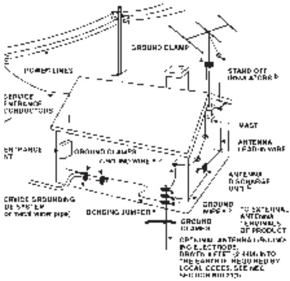
OUTDOOR ANTENNA GROUNDING
If an outside antenna is connected to your tuner or tuner-preamplifier, be sure the antenna system is grounded so as to provide some protection against voltage surges and built-up static charges. Section 810 of the National Electrical Code, ANSI/NFPA No. 70-1984, provides information with respect to proper grounding of the mast and supporting structure, grounding of the lead-in wire to an antenna discharge unit, size of grounding conductors, location of antenna discharge unit, connection to grounding electrodes and requirements for the grounding electrode.
a. Use No. 10 AWG (5.3mm ^2 ) copper, No. 8 AWG (8.4mm ^2 ) aluminium, No. 17 AWG (1.0mm ^2 ) copper-clad steel or bronze wire, or larger, as a ground wire.
b. Secure antenna lead-in and ground wires to house with stand-off insulators spaced from 4-6 feet (1.22 - 1.83 m) apart.
c. Mount antenna discharge unit as close as possible to where lead-in enters house.
d. Use jumper wire not smaller than No.6 AWG (13.3mm ^2 ) copper, or the equivalent, when a separate antenna-grounding electrode is used. see NEC Section 810-21 (j).
text_image
GROUND CLAMP PONEE LINES SERVICE ENTRENS CONDUCTORS ENTRANCE NT GROUND CLAMP CABY BOWING CRUISE SRODRING DE SPECT OF SHEET MOUNT PIPE; OCHGING JUMIFER STAND OFF INNOVATION VAST ANTENNA LEATH WARE ANTENNA SCHINNAGE OUTLET GROUND MARE ATTENNA ANTENNA ENVIRONMENTAL OF PRODUCT CABBAGE ANTENHALES INC ELECTROS. BRATTS OFF: 2 HU, INTO THE EARTH REDUCED BY LOCAL CECES. SCIENCE WHIP MOUNTINGEXAMPLE OF ANTENNA GROUNDING AS PER NATIONAL ELECTRICAL CODE INSTRUCTIONS CONTAINED IN ARTICLE 810 - RADIO AND TELEVISION EQUIPMENT.
NOTE TO CATV SYSTEM INSTALLER: This reminder is provided to call the CATV system installer's attention to Article 820-22 of the National Electrical Code that provides guidelines for proper grounding and, in particular, specifies that the ground cable ground shall be connected to the grounding system of the building, as close to the point of cable entry as practical.
text_image
B 2 3 4 5 1FRONT PANEL CONTROLS - NAD 710
text_image
NAO 1 2 3 4 5 02.00Figure 1
text_image
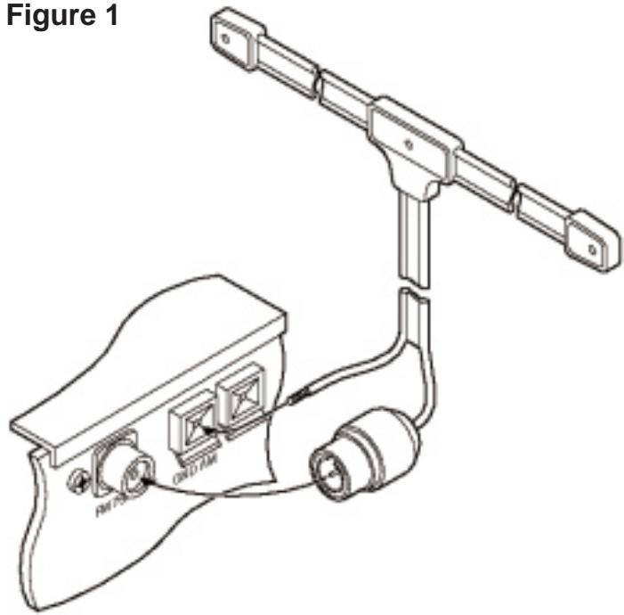
Figure 1 AIF-PO Box GRID-AMFFigure 2
text_image
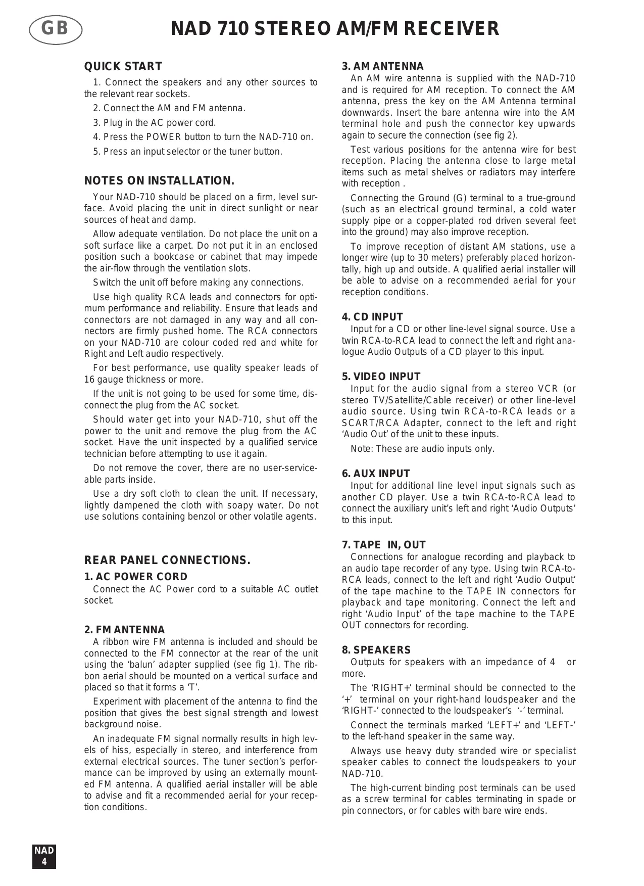
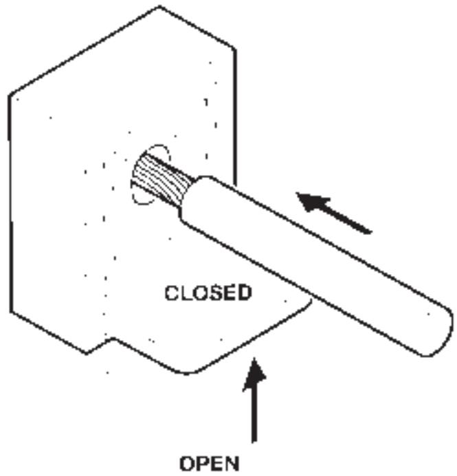
CLOSED OPENQUICK START
- Connect the speakers and any other sources to the relevant rear sockets.
- Connect the AM and FM antenna.
- Plug in the AC power cord.
- Press the POWER button to turn the NAD-710 on.
- Press an input selector or the tuner button.
NOTES ON INSTALLATION.
Your NAD-710 should be placed on a firm, level surface. Avoid placing the unit in direct sunlight or near sources of heat and damp.
Allow adequate ventilation. Do not place the unit on a soft surface like a carpet. Do not put it in an enclosed position such a bookcase or cabinet that may impede the air-flow through the ventilation slots.
Switch the unit off before making any connections.
Use high quality RCA leads and connectors for optimum performance and reliability. Ensure that leads and connectors are not damaged in any way and all connectors are firmly pushed home. The RCA connectors on your NAD-710 are colour coded red and white for Right and Left audio respectively.
For best performance, use quality speaker leads of 16 gauge thickness or more.
If the unit is not going to be used for some time, disconnect the plug from the AC socket.
Should water get into your NAD-710, shut off the power to the unit and remove the plug from the AC socket. Have the unit inspected by a qualified service technician before attempting to use it again.
Do not remove the cover, there are no user-service-able parts inside.
Use a dry soft cloth to clean the unit. If necessary, lightly dampened the cloth with soapy water. Do not use solutions containing benzol or other volatile agents.
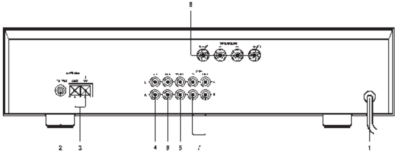
REAR PANEL CONNECTIONS.
1. AC POWER CORD
Connect the AC Power cord to a suitable AC outlet socket.
2. FM ANTENNA
A ribbon wire FM antenna is included and should be connected to the FM connector at the rear of the unit using the 'balun' adapter supplied (see fig 1). The ribbon aerial should be mounted on a vertical surface and placed so that it forms a 'T'.
Experiment with placement of the antenna to find the position that gives the best signal strength and lowest background noise.
An inadequate FM signal normally results in high levels of hiss, especially in stereo, and interference from external electrical sources. The tuner section's performance can be improved by using an externally mounted FM antenna. A qualified aerial installer will be able to advise and fit a recommended aerial for your reception conditions.
3. AM ANTENNA
An AM wire antenna is supplied with the NAD-710 and is required for AM reception. To connect the AM antenna, press the key on the AM Antenna terminal downwards. Insert the bare antenna wire into the AM terminal hole and push the connector key upwards again to secure the connection (see fig 2).
Test various positions for the antenna wire for best reception. Placing the antenna close to large metal items such as metal shelves or radiators may interfere with reception.
Connecting the Ground (G) terminal to a true-ground (such as an electrical ground terminal, a cold water supply pipe or a copper-plated rod driven several feet into the ground) may also improve reception.
To improve reception of distant AM stations, use a longer wire (up to 30 meters) preferably placed horizontally, high up and outside. A qualified aerial installer will be able to advise on a recommended aerial for your reception conditions.
4. CD INPUT
Input for a CD or other line-level signal source. Use a twin RCA-to-RCA lead to connect the left and right analogue Audio Outputs of a CD player to this input.
5. VIDEO INPUT
Input for the audio signal from a stereo VCR (or stereo TV/Satellite/Cable receiver) or other line-level audio source. Using twin RCA-to-RCA leads or a SCART/RCA Adapter, connect to the left and right 'Audio Out' of the unit to these inputs.
Note: These are audio inputs only.
6. AUX INPUT
Input for additional line level input signals such as another CD player. Use a twin RCA-to-RCA lead to connect the auxiliary unit's left and right 'Audio Outputs' to this input.
7. TAPE IN, OUT
Connections for analogue recording and playback to an audio tape recorder of any type. Using twin RCA-to-RCA leads, connect to the left and right 'Audio Output' of the tape machine to the TAPE IN connectors for playback and tape monitoring. Connect the left and right 'Audio Input' of the tape machine to the TAPE OUT connectors for recording.
8. SPEAKERS
Outputs for speakers with an impedance of 4 or more.
The ‘RIGHT+’ terminal should be connected to the ‘+’ terminal on your right-hand loudspeaker and the ‘RIGHT-’ connected to the loudspeaker’s ‘-’ terminal.
Connect the terminals marked 'LEFT+' and 'LEFT-' to the left-hand speaker in the same way.
Always use heavy duty stranded wire or specialist speaker cables to connect the loudspeakers to your NAD-710.
The high-current binding post terminals can be used as a screw terminal for cables terminating in spade or pin connectors, or for cables with bare wire ends.
SPADE CONNECTORS.
These should be slotted under the terminal's screw bushing, which is then fully tightened. Ensure the connector is tightly secured and there is no danger of bare metal from spade connectors touching the back panel or another connector, as this may cause damage.
BARE WIRES AND PIN CONNECTORS.
Bare wires and pin connectors should be inserted into the hole in the shaft of the terminal. Unscrew the speaker terminal's plastic bushing until the hole in the screw shaft is revealed. Insert the pin or bare cable end into the hole and secure the cable by tightening down the terminal's bushing.
Avoid any danger of bare metal from the speaker cables touching the back panel or another connector. Ensure that there is only 1/2" (1cm) of bare cable or pin and no loose strands of speaker wire.
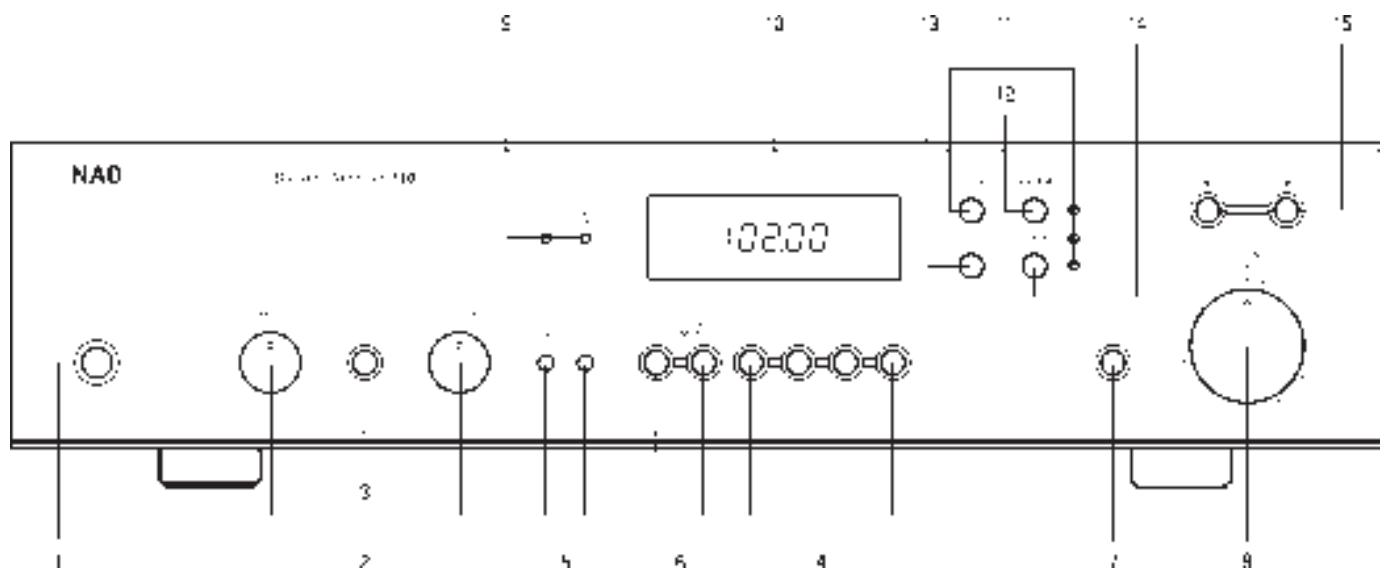
FRONT PANEL CONTROLS.
1. POWER
Press the POWER switch to turn the receiver On. The Display Panel will illuminate. Press the POWER switch again to turn the receiver Off.
The NAD-710 uses non-volatile memory to store pre-set information for the tuner so that these are not lost when the unit is switched off or unplugged.
2. BASS & TREBLE CONTROLS
The BASS and TREBLE tone controls adjust the tonal balance of your system.
The 12 o'clock position is 'flat' with no boost or cut and a detent indicates this position. Rotate the controls clockwise to increase, or anti-clockwise to decrease, the amount of Bass or Treble. The Tone controls do not affect recordings made using the TAPE or PORTABLE Outputs.
3. TONE DEFEAT
The TONE DEFEAT switch by-passes the tone control section of the NAD-710. If you normally leave the Tone Controls in the 12 o'clock position, then it is advisable to switch out the tone control section altogether by depressing the TONE DEFEAT switch. By-passing the Tone Control electronics ensures a slightly improved audio quality and an unaltered frequency response.
4. INPUT SELECTORS
These buttons select the active input to the NAD-710 and the signal sent to the loudspeakers, the TAPE and PORTABLE OUTPUTS. Press the button to latch it in and select the input. It will be released when a different input is selected.
VIDEO
Selects the VCR (or stereo TV/Satellite/Cable receiver) connected to the VCR sockets as the active input.
AUX
Selects a line-level source connected to the AUX sockets as the active input.
CD
Selects the CD (or other line-level source) connected to the CD sockets, as the active input.
TUNER
Selects the NAD-710's Tuner Section as the active input.
5. PORTABLE/INPUT CONNECTORS
Your NAD-710 has additional front panel PLAY/RECORD connectors to playback or record using a second system temporarily connected to the receiver. 3.5mm stereo mini-jack sockets are provided so that personal or portable stereo systems can be easily connected to your receiver. Standard Hi-Fi components that have RCA sockets can also be connected to these PLAY/RECORD sockets using a suitable 3.5mm/twin RCA adapter.
Press the PORTABLE button In to select the front panel Portable Input, and Out to return to normal operation.
The PORTABLE input will mix with any other input signal selected. So for example, by pressing CD and then selecting PORTABLE, you can use the NAD-710 to mix between two CD players (one connected CD and the other connected to PORTABLE).
6. TAPE MONITOR
Selects the output from a tape recorder when playing back tapes or monitoring recordings being made through the rear TAPE sockets. Press the TAPE MONITOR button once to select it, and again to return to the normal input selection.
This is a Tape Monitor function and will not cancel the current input selection. For example, if the CD is the active input when TAPE MONITOR is selected, CD will remain selected and its signal sent to the TAPE and PORTABLE output sockets. However the sound heard through the loudspeakers will be coming back from recorder connected to your receivers TAPE IN sockets.
TO MAKE A RECORDING.
When any source is selected, the signal is also fed directly to any tape machine connected to the TAPE or PORTABLE output, ready for recording.
TAPE-TO-TAPE COPYING.
You can copy between two tape machines connected to your NAD-710. Put the source tape in the recorder connected to PORTABLE and the blank tape into the recorder connected to TAPE. By selecting the PORTABLE input and then TAPE MONITOR you can now record from Portable to Tape and monitor the signal being recorded.
Note: Copying may be violating the copyright or property rights of the recordings owner.
VOLUME AND MONO.
7. MONO
Pressing the MONO button in switches the NAD-710 amplifier and tuner sections between Stereo and Mono Modes. Use Mono mode when the signal is present on only one of the two stereo input channels (left or right) or when receiving weak and hissy stereo FM signals. Pressing the button out returns to Stereo operation.
8. DUAL VOLUME CONTROL
The dual concentric volume knob combines the functions of Volume and Balance Control. The outer ring controls the level to the right-hand speaker and the inner section controls the level of the left-hand speaker. The two are friction-coupled so that they always move together when the volume control is adjusted.
To alter the balance between the two speakers, hold the outer ring and manually adjust the relative position of the VOLUME CONTROLS center section.
Adjusting the VOLUME CONTROL does not affect recordings made using the TAPE or PORTABLE outputs.
TUNER AND DISPLAY PANEL.
9. STEREO and CENTER TUNE INDICATORS
The CENTER TUNE indicator lights when you are correctly tuned to the station. The FM STEREO indicator lights when a stereo FM station is being received and the NAD-710 is switched into STEREO mode.
10. DISPLAY PANEL
The Display Panel is active all the time the NAD-710 is on and displays the frequency of the station that the tuner section is currently set to. When switching to STORE or PRESET Modes the display will flash for a few seconds, alternately showing the current Preset number and the station's frequency.
11. MODE SWITCH AND INDICATORS
The MODE button switches the tuner into either Tune, Preset or Search Modes. The indicator lights show which mode the Tuner section is currently in.
Tune Mode is for manually tuning onto a radio station.
Preset Mode is to call up stations already stored in the NAD-710's presets.
Search Mode will automatically search through the tuning frequencies and stop when it finds a broadcast station.
12. AM/FM
Press the AM/FM button to switch the NAD-710 between FM and AM (Medium wave) tuning. The Display Panel shows the frequency of the tuned station in MHz for FM and kHz for AM.
13. STORE
Press STORE to program a station into one of the NAD-710's twelve FM or twelve AM Preset memories.
To Store a station as a Preset, first select FM or AM and then tune to the station's frequency using Search or Tune Mode. Press STORE once and the display will flash, showing the station frequency and the current Preset number. Use the ▲▼ buttons to choose the Preset number you want to assign the station to. Press STORE again and the station will be programmed into that preset number.
14. LOCK
Pressing LOCK fine-tunes the NAD-710 into the station's frequency.
15. TUNE ▲▼
Use the TUNE ▲▼ buttons for tuning to the required station and to select Preset stations. In Tune Mode, pressing the ▲ or ▼ buttons increases or decreases the tuning frequency. Holding the button down quickly scans through the frequencies.
The CENTER TUNE indicator will light when a station is correctly tuned.
In Preset Mode, the ▲ and ▼ buttons are used to select radio stations stored in the tuners Preset memories.
TUNING AM & FM STATIONS.
Use TUNE mode to select a known station's frequency. SEARCH mode automatically looks for stations that are transmitting in your area.
TUNE MODE.
First select the AM or the FM band using the AM/FM button.
Press the MODE button until the TUNE indicator lights up. Press the ▲ or ▼ buttons to start manually locating a frequency. Holding the ▲ or ▼ buttons down will move quickly through the frequency range. When the required station has been located press LOCK to exactly tune to the station's frequency.
SEARCH MODE.
First select the AM or the FM band using the AM/FM button.
Press the MODE button until the SEARCH indicator lights up. Press the ▲ or ▼ buttons to start the tuner searching through the frequency band. When the tuner finds a broadcast signal of adequate strength, the automatic search will stop at that station. Press the ▲ or ▼ buttons again to continue searching for stations. Pressing the ▲ or ▼ buttons at any time will manually stop the search. When the required station has been located, press LOCK to exactly tune to the station's frequency.
STORING AND RECALLING PRESET AM & FM STATIONS.
To store a station as a Preset, first tune to the required frequency using either Search or Tune.
Press the STORE button. The Display Panel will show the current Preset number for approximately 5 seconds. Press ▲ or ▼ to select a different Preset number to store the station, if required.
Press the STORE button again to store the station's frequency as the chosen Preset number. The NAD-710 will then revert to normal operation.
The Preset information will be permanently held in memory unless you store another station over it.
To exit the Memory mode without storing a station, leave all the controls untouched; the Store mode will automatically cancel itself after approximately 5 seconds.
RECALLING A PRESET STATION.
First select the AM or the FM band using the AM/FM button and then press the Mode switch until the PRE-
SET indicator lights up. Press ▲ or ▼ to select one of the twelve FM, or twelve AM, Preset numbers. Each time these buttons are pressed, the display panel will flash for a few seconds showing the Preset number and the Presets frequency.
CHANGING A PRESET.
You can store a new station into a used Preset by simply going through the Preset storing process and placing a new station over the existing one.
TROUBLESHOOTING.
NO SOUND.
Power AC power cord unplugged or power not switched on.
Tape Monitor selected.
Portable input selected.
Station not selected or weak signal.
Thermal cut out operated.
Internal fuse blown.
Check AC power cord.
De-select Monitor mode.
De-select Portable input.
Re-tune.
Switch off and reduce volume setting. Switch on after unit has cooled.
Consult dealer.
NO SOUND ONE CHANNEL.
Volume Control balance not even.
Input lead disconnected or damaged.
Adjust inner and outer sections of Volume Control.
Check leads and connections.
WEAK BASS/ DIFFUSE STEREO IMAGE.
Speakers connected to the power amplifier wired out of phase.
Check the “+” and “−” connections to both speakers.
LOUD BUZZ OR HUM.
RCA connector not properly inserted or faulty lead.
Push all connectors firmly home, check leads.
TWO SIGNALS HEARD SIMULTANEOUSLY.
Portable mode selected and unit connected to the Portable is playing in addition to another selected input.
De-select Portable mode.
NOISE ON TUNER.
Hiss. Weak signal.
Distortion. Multi-path signals or interference from another station.
Whistles or buzzes on FM & AM. Interference from other electrical sources - computers, games consoles.
Whistles or buzzes on AM: Interference from fluorescent lighting or electrical motors.
Check station tuning. Adjust or replace antenna.
Check station tuning. Adjust or replace antenna.
Check station tuning. Switch off or move the source of the electrical noise.
Check station tuning. Adjust or replace AM antenna.
NO STATION FOUND IN SEARCH MODE.
Inadequate aerial signal.
Check aerial connections, adjust position of ribbon antenna.
MISE EN ROUTE RAPIDE
6. ENTREE AUX [AUX INPUT]
1. MARCHE/ARRET [POWER]
MODE RECHERCHE [SEARCH]
GRAVES FAIBLES / IMAGE STEREO DIFFUSE
BOURDONNEMENT OU RONFLEMENT IMPORTANT
5. IN- OCH UTGÅNGAR FÖR PORTABLA APPARATER.
7. TAPE IN/OUT (ENTRADA/SAÍDA DE/PARA TAPE)
Power Amplifier Section
CONTINUOUS AVERAGE POWER OUTPUT INTO 8 20W (13dBW)
(Min. power per channel, 20Hz-20kHz, both channels driven, with no more than rated distortion)
Rated distortion (THD 20Hz-20kHz) 0.05%
Clipping power (maximum continuous power per channel) 25W IHF dynamic headroom at 8 +3dB
IHF dynamic power 8 : 40W (17dBW) (maximum short term power per channel) 4 : 60W (17.8dBW) 2 : 80W (18.7dBW)
Damping factor (ref. 8 ohms 50Hz) >20 V/usec THD + SMPTE + IHF I.M. (from 250mV to rated output) <0.05%
Input impedance
Input sensitivity (for rated output into 8)
Signal/Noise ratio, A weighted ref. 1W ref. rated power
Frequency response 10Hz /70kHz
Line Level Inputs (CD, Video, Tape, Aux) Min vol 100dB
Input impedance (R and C) 80k +220 pF
Input sensitivity ref 0.5V 210mV
Maximum input signal >10 V
Signal/Noise ratio, A-weighted ref. 0.5V 93dB
ref. 1 W 106dB
Frequency response, 20Hz-20kHz +0.5 dB Infrasonic filter (fixed) -3 dB at 10Hz 12 dB/octave
Line Level Outputs
Output impedance Tape Source Source Z +1 k Maximum output level Tape out >5V
Controls
Bass ±7dB at 10kHz Treble ±6dB at 100Hz
FM Tuner Section
Input sensitivity Mono, -30dB THD+N 11.3dBf (1.0μV/75) Mono, 50dB S/N 15dBf (1.5μV/75) Stereo, 50dB S/N 37dBf (20μV/75) Stereo, 60dB S/N 47dBf (60μV/75)
Capture ratio (45 to 65dBf) <1.6dB AM rejection (45 to 65dBf) >60dB Selectivity Alternate channel 58dB
Adjacent channel Image rejection >80dB
I.F. rejection 90dB Subcarrier suppression (19 and 38kHz) 60dB THD at 100% modulation Mono, 1kHz <0.08% 100Hz-6kHz <0.2% Stereo, 1kHz <0.1% 100Hz-6kHz <0.3%
Signal/Noise ratio (at 65dBf, IHF weighted) Mono >80dB Stereo >74dB Frequency response, 30Hz-15kHz ±0.5dB Stereo separation 1kHz >45dB 30Hz-10kHz >35dB
AM Section
Usable sensitivity 10μV Selectivity 30dB Image rejection 45dB I.F. rejection 35dB Signal/Noise ratio (30% modn., 50mV input) 45dB THD 0.5%
Physical Specifications
Dimensions in mm (Width x Height x Depth) 435 x 76 x 295 Net Weight 3.9kg Shipping Weight 4.1kg
NAD ELECTRONICS LTD
(NEW ACOUSTIC DIMENSTION)
LONDON
©1996.710 I.M EDITION 1./697013 PRINTED IN THE PEOPLE'S REPUBLIC OF CHINA