
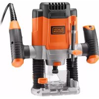
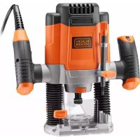
KW800E - Milling machine BLACK & DECKER - Free user manual and instructions
Find the device manual for free KW800E BLACK & DECKER in PDF.


| Product type | Router (plunge router) |
| Brand | Black & Decker |
| Model | KW800E |
| Nominal power | 800 W |
| Supply voltage | 230 V ~ 50 Hz |
| No-load speed | 10,000 - 30,000 rpm (variable) |
| Collet clamping capacity | 6 mm (1/4") |
| Plunge depth | 35 mm |
| Base diameter | 160 mm |
| Weight | 3.4 kg |
| Dimensions (L x W x H) | 280 x 180 x 220 mm |
| Base type | Fixed base |
| Main functions | Milling, grooving, profiling, template copying |
| Depth adjustment | Micrometric with stop |
| Spindle lock | Yes, for bit changes |
| Switch | With lock-on button |
| Dust extraction connection | Diameter 35 mm |
| Sound level (LpA) | 85 dB(A) |
| Vibration level | 5.0 m/s² |
| Maintenance and cleaning | Dust the ventilation grilles after each use; clean the base with a damp cloth |
| Safety | Lock-off switch; spindle lock; use safety glasses and mask |
| Spare parts and repairability | Carbon brushes, router bits, collets available as spare parts; repairable by authorized service center |
| Warranty | 2 years |
Frequently Asked Questions - KW800E BLACK & DECKER
You can also attach a parallel guide.
User questions about KW800E BLACK & DECKER
0 question about this device. Answer the ones you know or ask your own.
Ask a new question about this device
Download the instructions for your Milling machine in PDF format for free! Find your manual KW800E - BLACK & DECKER and take your electronic device back in hand. On this page are published all the documents necessary for the use of your device. KW800E by BLACK & DECKER.
USER MANUAL KW800E BLACK & DECKER
On the purchase of your Black & Decker product. To ensure the best results from your power tool please read these safety and usage instructions carefully. If you have any questions or queries after reading this user manual please do not hesitate to call our Service and Information Centre, whose number you will find towards the back of this user manual, or one of our Authorised Repair Agents. A list of these Agents and further information is available on the Internet at www.2helpU.com.
ESPANÕL
¡ENHORABUENA!
natural_image
Mechanical assembly diagram showing hands operating a component with arrows indicating motion direction (no text or symbols)natural_image
Illustration of hands using a mechanical tool to adjust or install a component (no text or symbols visible)natural_image
Technical line drawing of a mechanical assembly with no visible text or symbolsnatural_image
Mechanical assembly diagram showing a hand holding a screw and spring component (no text or labels)natural_image
Technical line drawing of a mechanical assembly with no visible text or symbolsnatural_image
Technical line drawing of a mechanical assembly with no visible text or symbolsnatural_image
Technical line drawing of a mechanical assembly with hands operating a component (no text or symbols visible)natural_image
Pure technical line drawing of a T-shaped component without any text, numbers, or symbolsnatural_image
Technical line drawing of a mechanical clamp or bracket component (no text or symbols)natural_image
Technical line drawing of a mechanical component with no visible text or symbolsnatural_image
Technical line drawing of a mechanical assembly with no visible text or symbolsnatural_image
Technical line drawing of a mechanical assembly with no visible text or symbolsSæt 'L'-stangen (a) på kantstøtteren (b) fast med de to medfølgende skruer og møtrikker. Fastgør den roterende anordning (c) på 'L'-stangen med
natural_image
Technical line drawing of a mechanical device with no visible text or symbols
flowchart
graph TD
    A["Start"] --> B{Condition}
    B -->|Yes| C["Process"]
    B -->|No| D["End"]
    C --> E["Feedback Loop"]
    E --> F["Loop Back"]
    F --> G["End"]
Brian Cooke - Director of Engineering
Black & Decker Ltd, Spennymoor, County Durham DL166JG, United Kingdom
natural_image
Mechanical assembly diagram showing hands operating a component with arrows indicating motion (no text or symbols)natural_image
Illustration of a hand using a tool to adjust or install a mechanical component (no text or symbols visible)natural_image
Technical line drawing of a mechanical assembly with a tool inserted (no text or symbols)natural_image
Technical line drawing of a mechanical assembly with springs and nuts (no text or symbols)Nach dem
Einstellen des
Dreifachtiefenan-
schlags wird ander
entsprechenden
Schraube mit
natural_image
Technical line drawing of a mechanical assembly with no visible text or symbolsnatural_image
Technical line drawing of a mechanical assembly with no visible text or symbolsnatural_image
Technical line drawing of a mechanical assembly with hands operating a component (no text or symbols visible)natural_image
Pure technical line drawing of a T-shaped component without any text, numbers, or symbolsnatural_image
Technical line drawing of a mechanical component with a central housing and bolted joints (no text or symbols)natural_image
Mechanical component diagram showing a knob and shaft assembly (no text or symbols)natural_image
Technical line drawing of a mechanical assembly with springs and a central circular component (no text or symbols)natural_image
Technical line drawing of a mechanical assembly with springs and levers (no text or symbols)natural_image
Technical line drawing of a mechanical device with rotating components and a base plate (no text or symbols)natural_image
Illustration of a hand using a mechanical tool to adjust or install a component (no text or symbols visible)natural_image
Mechanical assembly diagram showing a hand operating a tool on a mechanical component (no text or labels visible)natural_image
Technical line drawing of a mechanical assembly with springs and a handle (no text or symbols)natural_image
Technical line drawing of a mechanical assembly with no visible text or symbolsnatural_image
Technical line drawing of a mechanical assembly with no visible text or symbolsnatural_image
Technical line drawing of a mechanical assembly with hands operating components (no text or symbols)natural_image
Pure technical line drawing of a T-shaped component without any text, numbers, or symbolsnatural_image
Technical line drawing of a mechanical clamp or bracket component (no text or symbols)natural_image
Technical line drawing of a mechanical component with numbered slots (no text or symbols)natural_image
Technical line drawing of a mechanical assembly with springs and a central circular component (no text or symbols)natural_image
Technical line drawing of a mechanical assembly with no visible text or symbolsnatural_image
Technical line drawing of a mechanical assembly with no visible text or symbolsWarning! When using electric tools, the following basic safety precautions should always be taken to reduce the risk of fire, electric shock and personal injury. Read all these instructions before attempting to operate the product and save this booklet.
For safe operation:
- Keep the work area clean. Cluttered areas and benches invite injuries.
- Consider the work area environment. Do not expose the power tool to rain and do not use in damp or wet locations. Keep the work area well lit. Do not use the power tool where there is a risk to cause fire or explosion.
- Guard against electric shock. Avoid body contact, where possible, with earthed or grounded surfaces (e.g. pipes, radiators, ranges and refrigerators).
- Keep children away. Do not let visitors touch the tool or extension cord. All visitors should be kept away from the work area.
- Store idle tools. When not in use, tools should be stored in a dry, high or locked place, out of reach of children.
- Do not force the tool. It will do the job better and more safely at the rate for which it was intended.
- Use the right tool. Do not force small tools or attachments to do the job of a heavy duty tool. Do not use the tool for purposes not intended; for example, do not use a circular saw to cut tree limbs or logs.
- Dress properly. Do not wear loose clothing or jewellery as they can be caught in moving parts. Rubber gloves and non-skid footwear are recommended when working outdoors. Wear protective hair covering to contain long hair.
- Use safety glasses. Use a face or dust mask as well, if the operation is dusty or if the tool is being used in enclosed spaces.
- Connecting dust extraction equipment. If devices are provided for the connection of dust extraction and collection ensure these are connected and properly used, especially in confined areas.
- Do not abuse the cord. Never carry the tool by its cord or yank it to disconnect it from the socket. Keep the cord away from heat, oil and sharp edges.
- Secure the work. Use clamps or a vice to hold the work. It is safer than using a hand and it frees both hands to operate the tool.
-
Do not overreach. Keep proper footing and balance at all times.
-
Maintain the tool with care. Keep a cutting tool sharp and clean for better and safer performance. Follow the instructions for lubricating and changing accessories. Inspect the tools cord periodically and, if damaged, have repaired by an authorised service facility. Inspect the extension cord periodically and replace if damaged. Keep the handles dry, clean and free from oil and grease.
- Disconnect the tool when not in use, before servicing and when changing accessories such as blades, bits and cutters.
- Remove adjusting keys and wrenches. Form the habit of checking to see that keys and adjusting wrenches are removed from the tool and replaced in the storage area before switching on.
- Avoid unintentional starting. Do not carry a plugged-in tool with a finger on the switch. Ensure the switch is off when plugging in.
- Use an outdoor extension cord. When a tool is used outdoors, only use an extension cord intended for outdoor use and so marked.
- Stay alert. Watch what you are doing, use common sense and do not operate the tool when tired.
- Check damaged parts. Before further use of the tool, a guard or other part that is damaged should be carefully checked to determine whether it will operate properly and perform its intended function. Check for alignment of moving parts, free running of moving parts, breakage of parts, mounting and any other conditions that may affect its operation. A guard or other part that is damaged should be properly repaired or replaced by an authorised service centre unless otherwise indicated in the product booklet. Have defective switches replaced by an authorised service agent. Do not use the tool if the switch does not turn it on and off.
- Warning! The use of any accessory or attachment, other than recommended in the product booklet, may present a risk of personal injury.
- Have the tool repaired by a qualified person. The electrical tool is in accordance with the relevant safety requirements. Repairs should only be carried out by qualified persons using original spare parts, otherwise, this may result in considerable danger to the user.
Save these instructions!
DOUBLE INSULATION
The tool is double insulated. This means that all the external metal parts are electrically insulated from the mains power supply. This is done by
ENGLISH
placing insulation barriers between the electrical and mechanical components making it unnecessary for the tool to be earthed.
Note: Double insulation does not take the place of normal safety precautions when operating the tool. The insulation system is for added protection against injury resulting from a possible electrical insulation failure within the tool.
ELECTRICAL SAFETY
Be sure the supply is the same as the voltage given on the rating plate. The tool is fitted with a two-core cable and plug.
MAINS PLUG REPLACEMENT (UK ONLY)
Should the mains plug need replacing and you are competent to do this, proceed as instructed below. If you are in doubt, contact a Black & Decker service agent or a qualified electrician.
- Disconnect the plug from the power supply.
- Cut off the plug and dispose of safely. A plug with bared copper conductors is very dangerous if engaged in a live socket outlet.
- Only fit BS1363A approved plugs fitted with the correctly rated fuse.
Note: Fuses do not give personal protection against electric shock.
- The cable wire colours, or a letter, will be marked at the connection point of most good quality plugs. Attach the wires to their respective points in the plug (see diagram). Brown is L (live) and blue is N (neutral).
Fit a BS1363A
approved resilient plug
Connect blue to N (neutral)

Fit a 5 amp fuse
approved to BS1362
Connect brown to L (live)
Make sure that the outer sheath of the cable is held firmly by the clamp

230/240V AC only
Never use a light
socket
- Before replacing the top cover of the plug ensure that the cable restraint is holding the outer sheath of the cable firmly and that the two leads are correctly fixed at the terminal screws. If the fuse cover is missing or damaged do not use the plug.
For replacement or detachable fuse covers, contact a Black & Decker service agent.
Warning! Never connect live or neutral wires to the earth pin marked E or 12
REPLACEMENT OF THE SUPPLY CORD
(AUSTRALIA AND NEW ZEALAND ONLY)
If the supply cord is damaged, it must be replaced by the manufacturer or its service agent or similarly qualified person in order to avoid a hazard.
EXTENSION CABLES
Up to 30m (100ft) of 3-core extension cable can be used without undue loss of power. Note: An extension cable should not be used unless absolutely necessary. Use of an improper extension cable could result in a risk of fire and electric shock. If an extension cable must be used, make sure it is properly wired, contains the correct rated fuse as recommended in its literature and is in good electrical condition.
UNWANTED TOOLS AND THE ENVIRONMENT

Should you find one day that the tool needs replacement or is of no further use, think of the protection of the environment. Black & Decker service agents will accept old tools and will dispose of them in an environmentally safe way.
THE BLACK & DECKER GUARANTEE
(UK, AUSTRALIA AND NEW ZEALAND ONLY)
If the Black & Decker product becomes defective due to faulty materials and workmanship, within 24 months from the date of purchase, we guarantee to either replace all defective parts or at our discretion, replace the unit free of charge provided that:
• The product is returned to us or our authorised repairers with evidence of date of purchase.
• The product has not been used for trade, professional or hire purposes.
• The product has not been subjected to misuse or neglect.
• The product has not sustained any damage through foreign objects, substances or accidents.
• Repairs have not been attempted by anyone other than our own service staff or authorised repair distributors.
This guarantee is offered as an extra benefit and is additional to the customers statutory rights.
AFTER SALES SERVICE FOR YOUR BLACK & DECKER PRODUCT (UK, AUSTRALIA AND NEW ZEALAND ONLY)
Black & Decker offers a nationwide network of authorised service agents.



ENGLISH
The use of other than genuine Black & Decker accessories and parts may damage or reduce the performance of your Black & Decker product and may also endanger the user. The terms and conditions of the warranty may also be effected.
OUR AFTER SALES SERVICE POLICY (UK, AUSTRALIA AND NEW ZEALAND ONLY)
It is our aim that all Black & Decker customers should be totally satisfied with their Black & Decker product and after sales service, but if help or advice is needed please contact your local Black & Decker authorised repair agent who will be happy to help. Full details of our after sales service and a list of these agents can be found on the Internet at www.2helpU.com. Alternatively, call our Service and Information Centre whose number you will find towards the back of this manual.
ACCESSORIES
The performance of any power tool is dependant upon the accessory used. Black & Decker accessories are engineered to high quality standards and are designed to enhance the performance of your tool. Buying a Black & Decker accessory will ensure that you get the very best from your Black & Decker tool. For full details of accessories available, please consult your nearest stockist or service agent.
TECHNICAL DATA
The level of sound pressure of the tool is in accordance with EEC legislation. It is recommended that you take appropriate measures for the protection of your hearing if the sound level seems uncomfortable.
KW800 KW800E
Volts (V) \~ 230 230
Input power (W) 710800
No load speed/min 30,000 8,000-30,000
The Black & Decker policy is one of continuous improvement to our product and as such we reserve the right to change the product specification without prior notice.
Note: This user manual may also cover more than one catalogue number within this product group. Refer to your rating plate for details of your product. Your product includes some or all of these features.
FEATURES
- On/off switch
- Electronic speed switch (KW800E)
- Spindle lock
- Collet nut
-
Plunge lock lever
-
Triple depth stop
- Depth stop bar
- Allen wrench (for removing motor pack from frame)
- Wingscrew
- Vacuum adaptor
- Template guide
- Edge guide
- Centring pin
- Copy follower
- Distance plate

- Insert the desired cutter into the collet.
- Set the required depth of cut.
- Set the guide fence for the position of cut.
- Set the on/off switch to 'I'.
- Plunge your router down and lock.
- Route the workpiece.
- Release the plunge lock.
- Set the on/off switch to '0'.


ENGLISH
FITTING THE ROUTER BIT
Disconnect the plug from the electricity supply.

natural_image
Mechanical assembly diagram showing hands operating a component with arrows indicating motion (no text or symbols)If a router bit is already fitted, press the spindle lock button and release the collet clamp nut, using the spanner provided.

Insert the router bit. Make sure it protrudes at least 3mm from the end of the shank.
Press the spindle lock button and tighten the collet
clamp nut using the spanner provided.
ADJUSTING THE DEPTH OF CUT

The depth of cut is the distance (x) between the triple depth stop and the depth stop bar. Each router bit varies in length and the triple depth stop
provides three different positions. Use one of the following methods to set the depth of cut.
USING A PIECE OF WOOD
The most common method is to use a piece of wood as
a gauge as follows:
- Fit the router bit.
- Loosen the wing screw.
• Pull the plunge lock lever up
- Plunge your router down until the cutter is in contact with the workpiece.
- Push the plunge lock lever down to hold your router in this position.
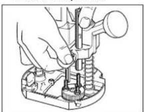
natural_image
Illustration of hands using a mechanical tool to adjust or install a component (no text or symbols visible)Pull up the depth stop bar.

natural_image
Technical line drawing of a mechanical assembly with no visible text or symbolsPut a piece of wood of the same thickness as the desired depth of cut, between the depth stop bar and the triple depth stop.
• Tighten the wing screw.
- Remove the piece of wood.
- Pull the plunge lock lever up to move your router back to its original position.
- Move your router to its working position and set the on/off switch to 'I'.
- Plunge your router down to the workpiece and push the plunge lock lever to hold your router at this depth.
- Make the desired cut.
USING THE SCALE
Proceed as follows:
- Fit the router bit.
- Loosen the wing screw.
• Pull the plunge lock lever up.
- Plunge your router down until the cutter is in contact with the workpiece.
- Push the plunge lock lever down to hold your router in this position. The scale on the depth stop bar now shows the starting position. This starting position will vary, depending on the cutter used.
- Add the desired depth of cut to the starting position; for example, if the scale shows 23mm and the desired depth of cut is 10mm, the correct adjustment on the scale is 23 + 10 = 33mm . If the scale shows 46mm and the desired depth of cut is 5mm, the correct adjustment on the scale is 46 + 5 = 51mm .
- Move the depth stop bar to the calculated number.
- Clamp the depth stop bar with the wing screw.
- Pull the plunge lock lever up to move your router to its original position.
- Move your router to its working position and set the on/off switch to 'I'.
- Plunge your router down to the workpiece and push the plunge lock lever to hold your router at this depth.
• Make the desired cut.
- For better quality cuts and a longer cutter life, make a series of cuts, instead of a single cut.


ENGLISH
FINE ADJUSTMENT WITH THE TRIPLE DEPTH STOP

natural_image
Mechanical assembly diagram showing a clamping tool interacting with a spring and nut (no text or labels)After turning the triple depth stop, fine adjustment is made with a screwdriver on the appropriate screw. When you wish to make several cuts at
different depths in the same material, adjust the three screws on the triple depth stop accordingly.
FITTING THE EDGE GUIDE
The edge guide is used when making parallel cuts or when making decorative edges.

natural_image
Technical line drawing of a mechanical assembly with no visible text or symbolsInsert two screws provided in the end holes in the edge guide and screw them into the threaded ends of the two bars. Insert the two bars in the grooves
in the base of your router. Adjust the guide to give the desired distance and tighten the two wing screws.
ALTERNATIVE GUIDE METHOD
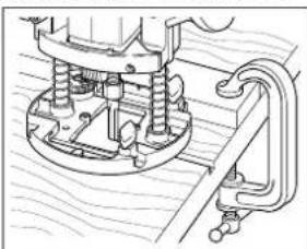
natural_image
Technical line drawing of a mechanical assembly with no visible text or symbolsWhen it is not possible to use an edge guide, (such as when routing grooves to support shelves in a bookcase end), use a straight piece of wood
clamped across the workpiece to act as a guiding edge.
FITTING THE VACUUM ADAPTOR
The vacuum adaptor enables the connection of a vacuum cleaner to your router to keep the workplace clean.
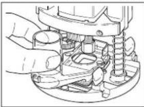
natural_image
Mechanical assembly diagram showing hands operating a component with springs and housing (no text or labels)Locate the vacuum adaptor on the base of your router. Insert the two long screws provided, from the bottom of the holes; place
two nuts on top of the adaptor and tighten the screws.
FITTING THE TEMPLATE GUIDE

natural_image
Pure technical line drawing of a T-shaped component without any text, numbers, or symbolsUse this guide to make a cutout shape from a template. The template is secured over the workpiece using double-sided tape or 'G' clamps. The
router bit extends below the template guide, to cut the workpiece in the shape of the template. In this way, a number of workpieces are made accurately to the same shape.

natural_image
Technical line drawing of a mechanical component with a central pin and mounting holes (no text or symbols)To fit the template guide, secure it to the base of your router using the two long screws provided.
ELECTRONIC SPEED REGULATION (KW800E)

natural_image
Mechanical component diagram showing a knob and shaft assembly (no text or symbols)The electronic speed switch permits the setting of the optimum speed to suit the router bit diameter and the material of the workpiece. This reduces the risk
of burning the workpiece, especially when crosscutting.
USING THE DISTANCE PIECE

natural_image
Technical line drawing of a mechanical assembly with springs and housing (no text or symbols)The distance piece is used when trimming wooden or laminate vertical projections. Attach the distance piece to the base using the screws provided.


ENGLISH
USING THE CENTRING PIN

natural_image
Technical line drawing of a mechanical assembly with gears and levers (no text or symbols)The centring pin enables you to use your router as a compass to cut out, scribe or produce circular patterns. Attach the
centring pin to the edge guide with the screw provided.
The copy follower helps maintain an equal cutting distance along the edge of irregularly shaped workpieces. To fit the copy follower, proceed as follows:

Attach the 'L' bar (a) to the edge guide (b) using the two screws and nuts provided. Attach the rotating attachment (c) to the 'L' bar with the wing screw
provided. Adjust the edge guide in the base of your router until the wheel is in contact with the workpiece.
ROUTER BITS
- Only use cutters with a shank size of 6mm, 8mm or 1/4" with the equivalent collet size provided.
Rounding, rebating and laminate bits have either a ball bearing or a pilot pin for use at the edge of the workpiece. Most of the following router bits are available in two different grades:
• HSS cutters for use on softwood.
• TCT cutters for use on hardwood, chipboard plastics and aluminium.
No Description Purpose
1 Straight bit Channelling
2 V-Grooving bit Chamfers, grooves and letter work
3 Core box bit Grooves, edge profiles and drop-leaf joints
4 Dovetail bit Dovetail grooves
5 Rounding bit Profiles and drop-leaf joints
6 Roman ogee bit Profiles
7 Rebating bit Easy rebates
8 Laminate bit Trimming wooden or laminate horizontal projections

HANDY HINTS

natural_image
Technical line drawing of a mechanical device with springs and a central component (no text or symbols)You can use your router without using a guide. This is useful for signwriting and creative work. Use only shallow cuts. The cutter of your router rotates clockwise. For more efficient cutting, move your router from left to

• When cutting outside edges, move your router anti-clockwise and clockwise when cutting inside edges.
TOOL CARE
Do not apply excessive pressure when you use your router. This can cause your router to overheat. If your router becomes too hot, operate it off-load for 2 minutes. Keep the air cooling vents on the motor clear.
EC DECLARATION OF CONFORMITY
We declare that units: KW800, KW800E conform to 98/37/EC, 89/336/EEC, EN55014, 73/23/EEC, EN50144, EN61000. A weighted sound pressure 85.5dB (A), A weighted sound power 98.5dB (A), Hand/arm weighted vibration 2.7m/s²

Brian Cooke, Director of Engineering
Black & Decker, Spennymoor, Co Durham DL16 6JG, UK
natural_image
Mechanical assembly diagram showing hand operating a component with arrows indicating motion direction (no text or symbols)natural_image
Illustration of a hand using a tool to adjust or install a mechanical component (no text or symbols visible)natural_image
Technical line drawing of a mechanical assembly with no visible text or symbolsnatural_image
Mechanical assembly diagram showing a hand adjusting a spring and nut component (no text or symbols visible)natural_image
Technical line drawing of a mechanical assembly with no visible text or symbolsnatural_image
Technical line drawing of a mechanical assembly with no visible text or symbolsnatural_image
Technical line drawing of a mechanical assembly with hands operating a component (no text or symbols visible)natural_image
Pure technical line drawing of a T-shaped component without any text, numbers, or symbolsnatural_image
Technical line drawing of a mechanical component with a central pin and mounting holes (no text or symbols)natural_image
Technical line drawing of a mechanical component with no visible text or symbolsnatural_image
Technical line drawing of a mechanical assembly with springs and a central circular component (no text or symbols)natural_image
Technical line drawing of a mechanical assembly with springs and levers (no text or symbols)natural_image
Technical line drawing of a mechanical assembly with no visible text or symbolsBlack & Decker Ltd, Spennymoor, County Durham,
DL166JG, RU
natural_image
Mechanical assembly diagram showing a clamping mechanism with arrows indicating motion (no text or symbols)natural_image
Technical line drawing of a mechanical assembly with hands operating a tool (no text or symbols visible)natural_image
Mechanical assembly diagram showing a valve mechanism with no visible text or symbolsnatural_image
Mechanical assembly diagram showing a hand adjusting a spring-loaded component (no text or symbols visible)natural_image
Technical line drawing of a mechanical assembly with no visible text or symbolsnatural_image
Technical line drawing of a mechanical assembly with no visible text or symbolsnatural_image
Mechanical assembly diagram showing hands operating a mechanical component (no text or labels visible)natural_image
Pure technical line drawing of a T-shaped component without any text, numbers, or symbolsnatural_image
Technical line drawing of a mechanical clamp or bracket assembly (no text or symbols)natural_image
Technical line drawing of a mechanical assembly with springs and housing (no text or symbols)natural_image
Technical line drawing of a mechanical assembly with no visible text or symbolsnatural_image
Technical line drawing of a mechanical device with springs and a base plate (no text or symbols)natural_image
Mechanical assembly diagram showing hands operating a component with arrows indicating motion (no text or symbols)natural_image
Technical line drawing of a mechanical assembly with hands operating a tool (no text or symbols visible)natural_image
Mechanical assembly diagram showing a valve mechanism with no visible text or symbolsnatural_image
Mechanical assembly diagram showing a hand adjusting a spring-loaded component (no text or symbols visible)natural_image
Technical line drawing of a mechanical assembly with no visible text or symbolsnatural_image
Technical line drawing of a mechanical assembly with no visible text or symbolsnatural_image
Mechanical assembly diagram showing hands operating a mechanical component (no text or symbols visible)natural_image
Pure technical line drawing of a T-shaped component without any text, numbers, or symbolsnatural_image
Technical line drawing of a mechanical component with a central hub and mounting holes (no text or symbols)natural_image
Technical line drawing of a mechanical assembly with gears and shafts (no text or symbols)natural_image
Mechanical assembly diagram showing a linkage mechanism with no visible text or symbolsnatural_image
Technical line drawing of a mechanical device with no visible text or symbolsBrian Cooke - Director of Engineering Black & Decker Ltd, Spennymoor, County Durham DL166JG, United Kingdom
natural_image
Mechanical assembly diagram showing hands operating a component with arrows indicating motion (no text or symbols)natural_image
Illustration of a hand using a tool to adjust or install a mechanical component (no text or symbols visible)natural_image
Mechanical assembly diagram showing a hand operating a tool on a mechanical component (no text or labels visible)natural_image
Technical line drawing of a mechanical assembly with bolts and springs (no text or symbols)natural_image
Technical line drawing of a mechanical assembly with no visible text or symbolsnatural_image
Technical line drawing of a mechanical assembly with no visible text or symbolsnatural_image
Mechanical assembly diagram showing hands operating a component with gears and springs (no text or labels)natural_image
Pure technical line drawing of a T-shaped component without any text, numbers, or symbolsnatural_image
Technical line drawing of a mechanical component with a central pin and mounting holes (no text or symbols)ELECTRONISCHE SNELHEIDSREGELING (KW800E)

natural_image
Technical line drawing of a mechanical component with no visible text or symbolsnatural_image
Technical line drawing of a mechanical assembly with springs and housing (no text or symbols)natural_image
Technical line drawing of a mechanical assembly with gears and shafts (no text or symbols)natural_image
Technical line drawing of a mechanical assembly with rotating components and a central component (no text or symbols)Black & Decker, Spennymoor, Co Durham DL16 6JG, UK
natural_image
Mechanical assembly diagram showing a hand operating a car wheel with arrows indicating motion direction (no text or symbols)natural_image
Hand operating a mechanical tool with threaded components and a base (no text or symbols visible)natural_image
Mechanical assembly diagram showing a valve mechanism with no visible text or symbolsnatural_image
Mechanical assembly diagram showing a hand adjusting a spring and screw component (no text or labels)natural_image
Technical line drawing of a mechanical assembly with no visible text or symbolsnatural_image
Technical line drawing of a mechanical assembly with no visible text or symbolsnatural_image
Technical line drawing of a mechanical assembly with hands operating a component (no text or symbols visible)natural_image
Pure technical line drawing of a T-shaped component without any text, numbers, or symbolsnatural_image
Technical line drawing of a mechanical component with a central pin and mounting holes (no text or symbols)natural_image
Technical line drawing of a mechanical component with numbered slots (1–10) and a handle, no readable text or symbols present.natural_image
Technical line drawing of a mechanical assembly with gears and shafts (no text or symbols)natural_image
Technical line drawing of a mechanical assembly with springs and levers (no text or symbols)natural_image
Technical line drawing of a mechanical device with rotating components and a base plate (no text or symbols)Brian Cooke - Director of Engineering
Black & Decker Ltd, Spennymoor, County Durham
DL166JG United Kingdom
natural_image
Mechanical assembly diagram showing hands operating a component with arrows indicating motion (no text or symbols)natural_image
Illustration of hands assembling a mechanical component with a tool (no text or symbols visible)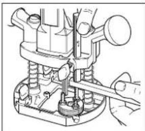
natural_image
Technical line drawing of a mechanical assembly with a hand operating a tool (no text or symbols visible)natural_image
Mechanical assembly diagram showing a hand adjusting a spring-loaded component (no text or symbols visible)natural_image
Technical line drawing of a mechanical assembly with no visible text or symbolsnatural_image
Technical line drawing of a mechanical assembly with no visible text or symbolsnatural_image
Mechanical assembly diagram showing hands operating a mechanical component (no text or symbols visible)natural_image
Pure technical line drawing of a mechanical component with no text or symbolsnatural_image
Technical line drawing of a mechanical clamp or bracket component (no text or symbols)natural_image
Technical line drawing of a mechanical component with numbered slots (no text or symbols)natural_image
Technical line drawing of a mechanical assembly with springs and housing (no text or symbols)natural_image
Technical line drawing of a mechanical assembly with gears and levers (no text or symbols)natural_image
Technical line drawing of a mechanical assembly with no visible text or symbolsBrian Cooke - Director of Engineering
Black & Decker, Spennymoor, County Durham
natural_image
Mechanical assembly diagram showing hands operating a component with arrows indicating motion (no text or symbols)natural_image
Illustration of hands using a mechanical tool to adjust or install a component (no text or symbols visible)natural_image
Technical line drawing of a mechanical assembly with a tool inserted (no text or symbols visible)natural_image
Mechanical assembly diagram showing a hand adjusting a spring-loaded component (no text or symbols visible)natural_image
Technical line drawing of a mechanical assembly with no visible text or symbolsnatural_image
Technical line drawing of a mechanical assembly with no visible text or symbolsnatural_image
Mechanical assembly diagram showing hands operating a mechanical component (no text or symbols visible)natural_image
Pure technical line drawing of a T-shaped component without any text, numbers, or symbolsnatural_image
Technical line drawing of a mechanical component with a central hub and mounting holes (no text or symbols)PORTAATON NOPEUDEN SÄÄDIN (KW800E)

natural_image
Technical line drawing of a mechanical assembly with no visible text or symbolsnatural_image
Technical line drawing of a mechanical assembly with gears and levers (no text or symbols)natural_image
Technical line drawing of a mechanical assembly with no visible text or symbolsÄlä paina jyrsintä
kovaa sitä
käyttäessäsi.
Tämä saattaa
aiheuttaa
jyrsimen
ylikuumenemisen.
Mikäli jyrsin
ylikuumenee,
anna sen käydä
tyhjäkäynnillä
2 minuuttia. Pidä
moottorin ilma-
aukot puhtaina.

CE-VAATIMUKSENMUKAISUUSTODISTUS
98/37/EC, 89/336/EEC, 73/23/EEC, EN50144, EN55014,
EN61000 mukaiset
Mitattu melupaine 85.5dB (A)
Brian Cooke - Director of Engineering
Black & Decker Ltd, Spennymoor, County Durham
DL166JG, United Kingdom
natural_image
Mechanical assembly diagram showing hands operating a brake caliper with directional arrows indicating motion (no text or labels)natural_image
Illustration of hands using a mechanical tool to adjust or install a component (no text or symbols visible)natural_image
Technical line drawing of a mechanical assembly with no visible text or symbolsnatural_image
Mechanical assembly diagram showing a hand adjusting a spring-loaded component (no text or symbols visible)natural_image
Technical line drawing of a mechanical assembly with no visible text or symbolsnatural_image
Technical line drawing of a mechanical assembly with no visible text or symbolsnatural_image
Mechanical assembly diagram showing hands operating a mechanical component (no text or symbols visible)natural_image
Pure technical line drawing of a T-shaped component without any text, numbers, or symbolsnatural_image
Technical line drawing of a mechanical component with a central pin and mounting holes (no text or symbols)natural_image
Mechanical component diagram showing a knob with numbered slots (no text or symbols)natural_image
Technical line drawing of a mechanical assembly with springs and housing (no text or symbols)natural_image
Technical line drawing of a mechanical assembly with no visible text or symbolsnatural_image
Technical line drawing of a mechanical device with no visible text or symbolsBrian Cooke - Director of Engineering Black & Decker Ltd, Spennymoor, County Durham DL166JG, United Kingdom

| Forhandler adresseHändleradresseΔιεύθυνση αντιπροσώπουAddress of dealerDirección del detallistaCachet du revendeurIndirizzo del rivenditoreAdres van de dealerForhandlerens adresseMorada do revendedorJälleenmyyjän osoiteÄterförsäljarens adress | IndkøbsdatoKaufdatumΗμερομηνία αγορὰσDate of purchaseFecha de compraDate d'achatData d'acquistoAankoopdatumInnkjøpsdatoData de compraOstopäiväInköpsdatum |
| Navn/Name/Ovoμα/Name/Nombre/Nom/Nome/Naam/Navn/Nome/Nimi/Namn: | machine cadeau?/Er maskinen en gave?/Recebeu esta ferramenta como presente?/Onko kone lahja?/Är maskinen en gäva?Ja/Ja/Nou/Yes/Si/Oui/Si/Ja/Ja/Sim/Kyllä/JaNej/Nein/Oχ/No/No/Non/No/Nee/Nei/Não/Ei/NejHvor meget kostede maskinen?/Was war der Preis dieses Werkzeuges?/Ποιά ειναι τιμή του εργαλείου autού/?/What was the price of this tool?/?Cual fue el precio de esta herramienta?/Prix payé?/?Quanto ha pagato questo prodotto?/?Wat was de prijs van dit produkt?/?Hvor meget kostet maskinen?/?Que preço pagou por esta ferramenta?/?Paljonko kone maksoi?/?Hur myket kostade maskinen?____Er dette din første B&D maskine?/?Ist dieses Werkzeug-?/Eivai to εργαλείου autó-/Is this tool-/?Es esta herramienta que comprado-/Est-ce-/Questo prodotto è-/Is deze machine-/-/Erdette din første B&D maskin?/?Esta ferramenta é-/Onkotämä ensimmäinen B&D-koneesi?/?Är detta Din första B&D-velu? | Ja/ein Erstkauf?/?η πρώτη σσα αγορά?/your first purchase?/?la primera de este tipo?/?un ler achat?/?il suo primo acquisto?/?uw eerste aankoop?/?Ja/a sua primeira compra?/?Kyllä/JaNej/Ersatzkauf?/?για αντικατάσταση?/?a replacement?/?un reempalzo?/?un achat de remplacement?/?una sostituzione?/?een vervanging?/?Nei/uma substitução?/?Ei/NejForhandler adresse/Händleradresse/Διεύθυνση αντιπροώμτου/Address of dealer/Dirección del detallista/Cachet du revendeur/Indirizzo del rivenditore/Dealeradres/Forhandlerens adresse/Morada do revendedor/Jälleenmyyjän osoite/Äterförsäljarens adress:Cat.no.KW800/_ | Venligst sæt kryds i ruden säfremt De ikke måtte ønske at modtage information fra anden virksomhed end Black & Decker.Bitte ankreuzen, falls Sie weiteres Informationsmaterial von Black & Decker erhalten möchten.Паракалейσθε να σμειώσετε εᾶν δέν θέλετε να πάρετε πληροφορίεσ αλλησε σταιρείασ εκτόσ τησ βλα & Decker.Data protection act: Tick the box if you prefer not to receive information from us or others.Señale en la casilla sino quiere recibir información de otras empresas.Sivous ne souhaitez pas recevoir d'informations de la part d'autres sociétés que Black & Decker, cochez cette case.Barrate la casella se non desiderate ricevere informazioni da altre aziende.A.u.b.dit vakje aankruisen indien u geen informatie wenst te ontvangen van andere bedrijven dan Black & Decker.Vennligst kryss av dersom De ikke ønsker informasjon fra andre bedrifter enn Black & Decker.Por favor, assinale com uma cruz se desejar receber informação de outras empresas, além da Black & Decker.Merkitkää rasti ruutuun, mikäli ette halua vastaanottaa informaatiota muulta taholta kuin Black & Deckeriltä.Vänligen kryssa för i rutan om Ni inte vill ha information från andra företag än Black & Decker. |
| Adresse/Adresse/ΔιεύθυνσηAddress/Dirección/Adresse/Indirizzo/Adres/Adresse/Morada/Osoite/Adress: | |||
| By/Wohnort/Πὸλη/Town/Ciudad/Ville/Cittá/Plaats/By/Localidade/Paikkakunta/By: | |||
| Postnr./Postleitzahl/Kwōδικόσ/Postcode/Code postal/Código/Codice postale/Postcode/Postnr./Código postal/Postinumero/Postnr.: | |||
| Er maskinen en gave?/?Ist diese Maschine ein Geschenk?/?Η μηχανή είναι δώρο?/?Is this product a gift?/?Ha recibido usted esta herramienta como regalo?/?S'agit-il d'un cadeau?/?Si tratta di un regalo?/?Kreeg u deze |


| 10/10 | ||||
| Dammark | Veniligstkilip denne del ud sog sand frankeretil Black & Decker i ditland. | Per favore trifagile guesta parte, insertela in una busta con tancobollo e speditela subito dopo l'acquistio del prodotto allindirizzo delila Black & Decker nellia vostra nazione (vedi sopra). | Italieno | Sverige |
| Deutsch | Brite schiniden Sie diesen Abschinit ab, stecken ihn in einen frankerten Umscihag und schicken ihn direktan die Black & Decker Adresse Ihres Landes. | Kinp dit gedelete uit, zend hit en een gefrankerde, gaderesseerde envielp direct na uw aankoop naar het Black & Decker-ades in uw land (zie boven). | Nederlands | Norge |
| Elihynko | Thapapackau koute uto koujati kcal TaxUpolpte to aizcawu leta tvy ayopd tou produvto oca cony beluguvon into Black & Decker ordinary alzuda (pazinte radw). | Veniligst kilpp ut denne deien umiddelbar etter du har pakket udt lit produktoog legg del i en adresser konvollit ti Black & Decker (Norge) A/S (se adresse over). | Norge | Please complete this section immediately after the purchase of your product and post itto the Black & Decker addresses in your country (above). If you live in Australia or New Zealand, please register by using the alternative guarantee card supplied. |
| English | Please complete this section immediately after the purchase of your product and post itto the Black & Decker addresses in your country (above). If you live in Australia or New Zealand, please register by using the alternative guarantee card supplied. | Portugues For favor, recorte esta parte, coloque-a num envelope selado e anderegado e envie-o logo apos a compra do seu produto para o nderego da Black & Decker do seu pais. | Suomi Leikkara irti tamä osa, Ialta se ohisleen kurenen jA postita kuori yllä olevaan paikailiessen Black & Decker ostiteseen. | for favor, esta tarifeta i a central de Black & Decker en su pais. |
| Español Despues de haber comprado su häramientos anvie used, por favor, esta tarifeta i a central de Black & Decker en su pais. | Etsar de Black & Decker dans vorte pays (voir ci-dessus), arteresse de Black & Decker dans vorte pays (voir ci-dessus), arteresse de Black & Decker dans vorte pays (voir ci-dessus), arteresse de Black & Decker dans vorte pays (voir ci-dessus), arteresse de Black & Decker dans vorte pays (voir ci-dessus), arteresse de Black & Decker dans vorte pays (voir ci-dessus), arteresse de Black & Deckers adressi Ditt land (se oven). | Suisse | I, adresse de Black & Decker dans vorte pays (voir ci-dessus), secil immedatement aprees vorte achat. | |
| Français | Decoupes cette partie et envoyez-la sous enveloppe timbree a l, adresse de Black & Decker dans vorte pays (voir ci-dessus), seur le anterkeratkourt, och sand det genssttil Black & Decker adressi Ditt land (se oven). | Suisse | Suisse | |
| • GARANTIKORT • GARANTIEKARTE • KAPTA EFFYHZH • GUARANTEE CARD • TARGETA DE GARANTIA • CARYE DE GARANTIE | ||||||
| • TAGULANDO DI GABANZIA • GARANTIE-KART • GARANTI KORT • CARTAO DE GARANTIA • TAKUKORITI • GARBANTIBEVS | ||||||
| Belgique/Belgie | Weihoeck 1, 1930Zaventem | Nederland | Förinstraat 10, 4879AH Etten-Leur | Norge | Stromsveien 344, 1081 Ostlo | Erlaarer Strabe 165, 1231 Wien |
| Dänmark | Heieraving 26B, 3450 Alléred | Norge | Österreich | Portugal Rua Egas, Moniz 173, S. Bogodó Estoril, 2768 Estoril Codex | Portugal Rua Egas, Moniz 173, S. Bogodó Estoril, 2768 Estoril Codex | South Africa |
| Deutschland | Black & Decker Star, 40, D-65510 Idstein | Österreich | Erlaarer Strabe 165, 1231 Wien | Portugal Rua Egas, Moniz 173, S. Bogodó Estoril, 2768 Estoril Codex | Portugal Rua Egas, Moniz 173, S. Bogodó Estoril, 2768 Estoril Codex | South Africa |
| España | 43883 Roda de Bara (Tarragona) | Black & Decker, Suite 107, PN X65, Hafway Hse, 1685 | Suniti | Black & Decker OY, Ralisstie 7C, 01510Vantaa | Sverige | Box 603, 421 26Vastra Frolundad |
| France | BP21, 69571 Dardilly Cedex | Suniti | Black & Decker OY, Ralisstie 7C, 01510Vantaa | Swinege | Box 603, 421 26Vastra Frolundad | UK& Ireland |
| Helvetia | Ruitstrabe 14, 89522 Schilleren, Schweiz/Suisse | Swinege | Box 603, 421 26Vastra Frolundad | Sverige | Box 603, 421 26Vastra Frolundad | UK& Ireland |
| Italia | Viale Eivizia 2, 20052 Monza (Mll) | UK& Ireland | PO Box 821, Slough, Berkshire, SL134R | |||

- ESPANÕL
- ¡ENHORABUENA!
- For safe operation:
- Save these instructions!
- DOUBLE INSULATION
- ENGLISH
- ELECTRICAL SAFETY
- MAINS PLUG REPLACEMENT (UK ONLY)
- REPLACEMENT OF THE SUPPLY CORD
- (AUSTRALIA AND NEW ZEALAND ONLY)
- EXTENSION CABLES
- UNWANTED TOOLS AND THE ENVIRONMENT
- THE BLACK & DECKER GUARANTEE
- (UK, AUSTRALIA AND NEW ZEALAND ONLY)
- AFTER SALES SERVICE FOR YOUR BLACK & DECKER PRODUCT (UK, AUSTRALIA AND NEW ZEALAND ONLY)
- OUR AFTER SALES SERVICE POLICY (UK, AUSTRALIA AND NEW ZEALAND ONLY)
- ACCESSORIES
- TECHNICAL DATA
- KW800 KW800E
- FEATURES
- FITTING THE ROUTER BIT
- ADJUSTING THE DEPTH OF CUT
- USING A PIECE OF WOOD
- USING THE SCALE
- FITTING THE EDGE GUIDE
- FITTING THE VACUUM ADAPTOR
- ROUTER BITS
- No Description Purpose
- TOOL CARE
- EC DECLARATION OF CONFORMITY
- CE-VAATIMUKSENMUKAISUUSTODISTUS
Brand : BLACK & DECKER
Model : KW800E
Category : Milling machine