
XTW1500E - Milling machine BLACK & DECKER - Free user manual and instructions
Find the device manual for free XTW1500E BLACK & DECKER in PDF.


| Product type | Router |
| Brand | Black & Decker |
| Model | XTW1500E |
| Voltage | 230 V |
| Power consumption | 1 600 W |
| No-load speed | 11 000 - 28 000 min-1 |
| Collet chuck | 1/2" (12.7 mm) / 1/4" (6.35 mm) / 8 mm / 6 mm |
| Max. router bit diameter | 42 mm |
| Max. cutting depth | 60 mm |
| Weight | 5.1 kg |
| Double insulation | Yes, no ground cable needed |
| Intended use | Routing of wood and wood products, domestic use |
| Variable speed | Yes, electronic adjustment |
| Turret depth stop | Yes, adjustable for multiple depths |
| Spindle lock | Yes, for bit change |
| Dust extraction | Vacuum adapter supplied |
| Maintenance | Clean ventilation slots with a soft brush; motor compartment with damp cloth, no abrasives |
| Safety | General and specific instructions; wearing safety glasses and dust mask recommended |
| Warranty | 2 years standard, 3 years if registered on blackanddecker.fr/xt within 90 days |
| Included accessories | Guide shoe, extraction adapter, template guide, spacer piece, centering pin, copy follower |
Frequently Asked Questions - XTW1500E BLACK & DECKER
User questions about XTW1500E BLACK & DECKER
0 question about this device. Answer the ones you know or ask your own.
Ask a new question about this device
Download the instructions for your Milling machine in PDF format for free! Find your manual XTW1500E - BLACK & DECKER and take your electronic device back in hand. On this page are published all the documents necessary for the use of your device. XTW1500E by BLACK & DECKER.
USER MANUAL XTW1500E BLACK & DECKER
English 6
Deutsch 12
Français 19
Italiano 25
Nederlands 31
Español 37
Português 44
Svenska 51
Norsk 57
Dansk 63
Suomi 69
Ελληνικα


natural_image
Technical line drawing of a mechanical assembly with labeled component 'E' (no text or symbols beyond label)


natural_image
Technical line drawing of a mechanical device with internal components and motion lines (no text or symbols)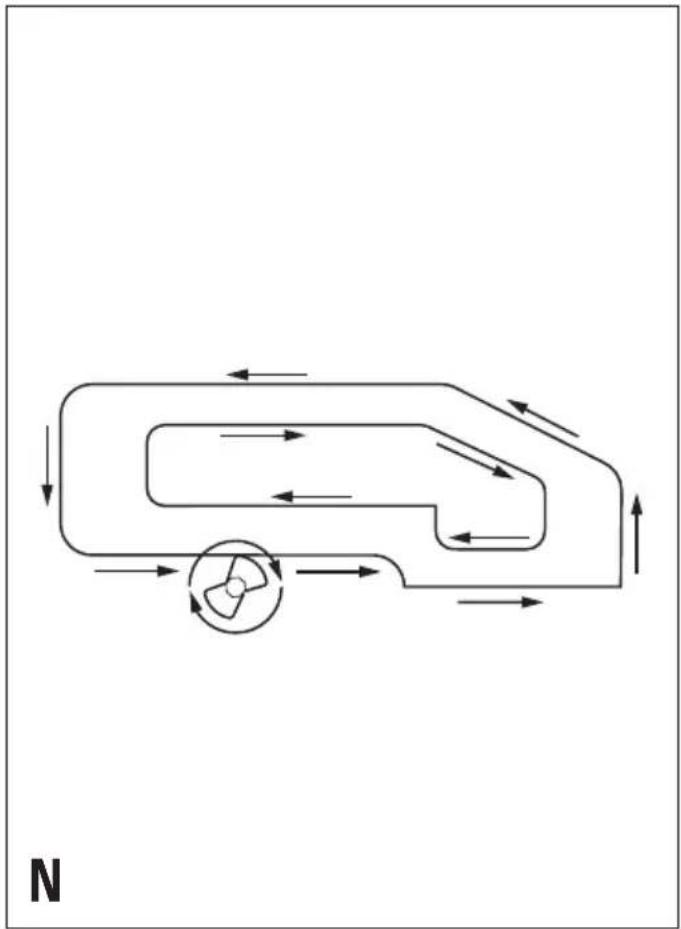
natural_image
Diagram of a mechanical or fluidic system with directional arrows and a central rotating component (no text or symbols)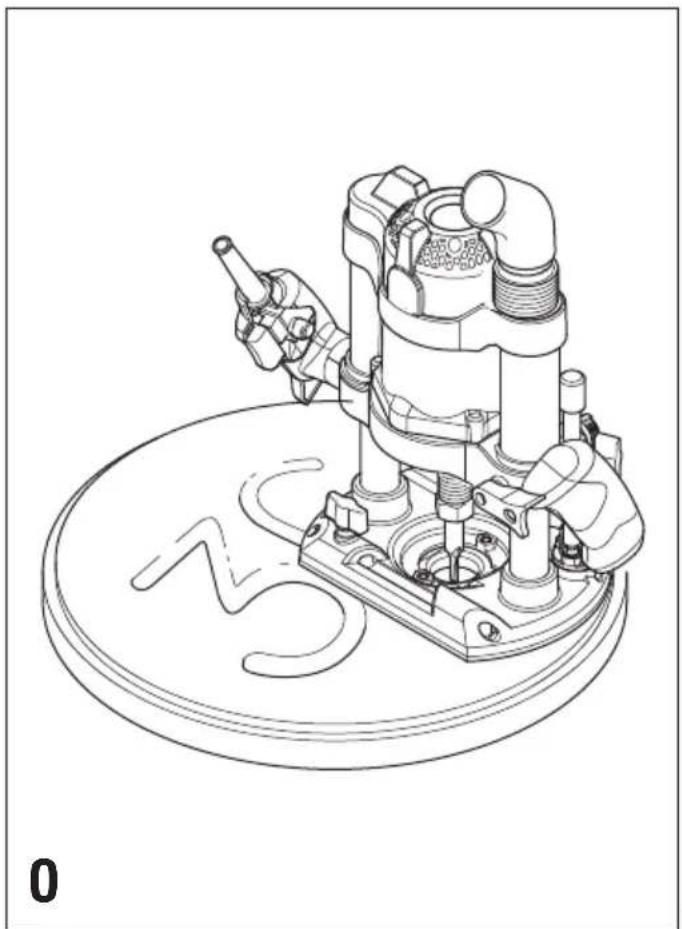
natural_image
Technical line drawing of a mechanical assembly with no visible text or symbols
ENGLISH
Intended use
Your Black & Decker router has been designed for routing wood and wood products. This tool is intended for consumer use only.
General safety rules
Warning! Read all instructions. Failure to follow all instructions listed below may result in electric shock, fire and/or serious injury. The term "power tool" in all of the warnings listed below refers to your mains operated (corded) power tool or battery operated (cordless) power tool. SAVE THESE INSTRUCTIONS.
1. Work area
a. Keep work area clean and well lit. Cluttered and dark areas invite accidents.
b. Do not operate power tools in explosive atmospheres, such as in the presence of flammable liquids, gases or dust. Power tools create sparks which may ignite the dust or fumes.
c. Keep children and bystanders away while operating a power tool. Distractions can cause you to lose control.
2. Electrical safety
a. Power tool plugs must match the outlet. Never modify the plug in any way. Do not use any adapter plugs with earthed (grounded) power tools. Unmodified plugs and matching outlets will reduce risk of electric shock.
b. Avoid body contact with earthed or grounded surfaces such as pipes, radiators, ranges and refrigerators. There is an increased risk of electric shock if your body is earthed or grounded.
c. Do not expose power tools to rain or wet conditions.
Water entering a power tool will increase the risk of electric shock.
d. Do not abuse the cord. Never use the cord for carrying, pulling or unplugging the power tool. Keep cord away from heat, oil, sharp edges or moving parts. Damaged or entangled cords increase the risk of electric shock.
e. When operating a power tool outdoors, use an extension cord suitable for outdoor use. Use of a cord suitable for outdoor use reduces the risk of electric shock.
3. Personal safety
a. Stay alert, watch what you are doing and use common sense when operating a power tool. Do not use a power tool while you are tired or under the influence of drugs, alcohol or medication. A moment of inattention while operating power tools may result in serious personal injury.
b. Use safety equipment. Always wear eye protection.
Safety equipment such as dust mask, non-skid safety shoes, hard hat, or hearing protection used for appropriate conditions will reduce personal injuries.
c. Avoid accidental starting. Ensure the switch is in the off position before plugging in. Carrying power tools with your finger on the switch or plugging in power tools that have the switch on invites accidents.
d. Remove any adjusting key or wrench before turning the power tool on. A wrench or a key left attached to a rotating part of the power tool may result in personal injury.
e. Do not overreach. Keep proper footing and balance at all times. This enables better control of the power tool in unexpected situations.
f. Dress properly. Do not wear loose clothing or jewellery. Keep your hair, clothing and gloves away from moving parts. Loose clothes, jewellery or long hair can be caught in moving parts.
g. If devices are provided for the connection of dust extraction and collection facilities, ensure these are connected and properly used. Use of these devices can reduce dust related hazards.
4. Power tool use and care
a. Do not force the power tool. Use the correct power tool for your application. The correct power tool will do the job better and safer at the rate for which it was designed.
b. Do not use the power tool if the switch does not turn it on and off. Any power tool that cannot be controlled with the switch is dangerous and must be repaired.
c. Disconnect the plug from the power source before making any adjustments, changing accessories, or storing power tools. Such preventive safety measures reduce the risk of starting the power tool accidentally.
d. Store idle power tools out of the reach of children and do not allow persons unfamiliar with the power tool or these instructions to operate the power tool.
Power tools are dangerous in the hands of untrained users.
e. Maintain power tools. Check for misalignment or binding of moving parts, breakage of parts and any other condition that may affect the power tools operation. If damaged, have the power tool repaired before use. Many accidents are caused by poorly maintained power tools.
f. Keep cutting tools sharp and clean. Properly maintained cutting tools with sharp cutting edges are less likely to bind and are easier to control.
g. Use the power tool, accessories and tool bits etc., in accordance with these instructions and in the manner intended for the particular type of power tool, taking into account the working conditions and the work to be performed. Use of the power tool for operations different from those intended could result in a hazardous situation.
5. Service
a. Have your power tool serviced by a qualified repair person using only identical replacement parts. This will ensure that the safety of the power tool is maintained.
Additional safety instructions for routers
- Only use router bits with a shank diameter equal to the size of the collet installed in the tool.
◆Only use router bits suitable for the no-load speed of the tool.
◆Never use router bits with a diameter exceeding the maximum diameter specified in the technical data section.
◆Hold the tool by the handles as indicated.
◆Do not use the tool in an inverted position.
◆Do not attempt to use the tool in a stationary mode.
◆Remove all nails and metal objects from the workpiece before routing.
Before cutting into walls, floors or ceilings, check for the location of wiring and pipes.
◆Take special care when routing MDF or surfaces coated with lead-based paint:
- Wear a dust mask specifically designed for protection against lead paint dust and fumes and ensure that persons within or entering the work area are also protected.
- Do not let children or pregnant women enter the work area.
- Do not eat, drink or smoke in the work area.
- Dispose of dust particles and any other debris safely.
◆Always wear a dust mask.
Electrical safety

This tool is double insulated; therefore no earth wire is required. Always check that the power supply corresponds to the voltage on the rating plate.
◆This appliance is not intended for use by young or infirm persons without supervision. Children must be supervised to ensure they do not play with the appliance.
◆If the supply cord is damaged, it must be replaced by the manufacturer or an authorised Black & Decker Service Centre in order to avoid a hazard.
Features
- On/off switch
- Lock-off button
- Handle
- Variable speed control knob
- Plunge lock lever
- Spindle lock button
- Collet
- Revolver depth stop
- Depth stop bar
- Chip deflector
- Dust extraction adaptor
Assembly
Warning! Before assembly, make sure that the tool is switched off and unplugged.
Fitting a router bit (fig. A)
◆Remove the chip deflector (10) by pulling it straight up from the router base.
Warning! Beware not to bend the chip deflector.
◆Keep the spindle lock button (6) depressed and rotate the spindle until the spindle lock fully engages.
◆Loosen the collet nut (17) using the spanner provided.
◆Insert the shank of the router bit (18) into the collet (7). Make sure that the shank protrudes at least 3 mm from the collet as shown.
◆Keep the spindle lock button (6) depressed and tighten the collet nut (17) using the spanner provided.
Fitting the edge guide (fig. B)
The edge guide (12) helps to guide the tool parallel to an edge.
◆Insert the bars (19) into the router base as shown.
◆Set the edge guide to the required distance.
◆Tighten the fixing screws (20).
Fitting the dust extraction adaptor (fig. C)
The dust extraction adaptor allows you to connect a vacuum cleaner to the tool.
◆Place the dust extraction adaptor (11) onto the dust extraction outlet as shown.
◆Connect the hose (23) of the vacuum cleaner to the adaptor (11).
Fitting the template guide (fig. D)
◆Fit the template guide (13) to the base of the router, with the flange to the bottom (workpiece) side.
◆Insert the two long screws (24) from the bottom side through the template guide and the holes in the base.
◆Place a nut onto each of the screws and securely tighten the nuts.
ENGLISH
Fitting the distance piece (fig. E)
◆Fit the distance piece (14) to the base of the router using the screws provided.
Fitting the centring pin (fig. F)
◆Fit the edge guide to the router as shown in fig. B, but upside down.
◆Fit the centring pin (15) to the workpiece side of the edge guide with the screw (25) provided.
Fitting the copy follower (fig. G)
◆Fit the edge guide to the router as shown in fig. B.
◆Fit the 'L' bar (16) to the upper side of the edge guide using the two screws and nuts provided.
Adjust the rotating attachment (26) on the 'L' bar with the wing knob (27).
Fitting the additional edge guide (fig. H)
The additional guide (21) is designed to allow routing of a thin piece of wood (e.g. the edge of a door).
◆Adjust the edge guide (12) as necessary.
◆Loosen the fixing screws (28).
◆Fit the edge guide (21) to the bars (19) protruding from the router base.
Adjust the edge guide so the workpiece becomes clamped between the two edge guide.
◆Tighten the fixing screws (28).
Use
Warning! Let the tool work at its own pace. Do not overload.
◆Carefully guide the cable in order to avoid accidentally cutting it.
Adjusting the depth of cut (fig. I, J & K)
The depth of cut is the distance X between the depth stop bar (9) and the depth stop (29). The depth of cut can be set in two different ways as described below.
Adjusting the depth of cut using the scale (fig. J)
◆Fit the router bit as described above.
◆Loosen the locking screw (30).
◆Pull the plunge lock lever (5) up.
◆Plunge the router down until the router bit touches the workpiece.
◆Push the plunge lock lever (5) down.
◆Move the depth stop bar (9) down against the depth stop using the depth stop adjuster (31). Reset the scale by aligning the zero marking (32) with the arrow (33).
◆Move the depth stop bar (9) to the calculated position using the depth stop adjuster (31). One quarter turn corresponds to approx. 6.25 mm.
◆Tighten the locking screw (30).
◆Fine adjust using the adjusting knob (34). One full turn corresponds to approx. 1 mm.
◆Pull the plunge lock lever (5) up and return the router to its original position.
◆After switching the router on, plunge it down and make the desired cut.
Adjusting the depth of cut using a piece of wood (fig. K)
◆Fit the router bit and plunge the router down as described above.
◆Loosen the locking screw (30).
◆Move the depth stop bar (9) up using the depth stop adjuster (31).
◆Place a piece of wood with a thickness equal to the desired depth of cut between the depth stop (29) and the depth stop bar (9).
◆Move the depth stop bar (9) down against the wood using the depth stop adjuster (31).
◆Tighten the locking screw (30).
◆Fine adjust using the adjusting knob (34).
◆Remove the piece of wood.
◆Pull the plunge lock lever (5) up and return the router to its original position.
◆After switching the router on, plunge it down and make the desired cut.
Adjusting the revolver depth stop (fig. L)
After turning the revolver depth stop to the desired setting, you can fine-adjust the depth stop to be used. If you want to make several cuts with a different depth of cut, adjust each of the depth stops.
◆Turn the depth stop screw (35) up or down as required using a screwdriver.
Setting the speed
◆Set the speed control knob (4) to the required speed. Use a high speed for small diameter router bits. Use a low speed for large diameter router bits.
Using a batten as a guide (fig. M)
When it is not possible to use the edge guide, for example when routing grooves in the back panel of a bookcase to support shelves, proceed as follows:
- Select a piece of wood with a straight edge to use as a batten.
◆Place the batten onto the workpiece.
◆Move the batten until it is in the correct position to guide the tool.
◆Securely clamp the batten to the workpiece.
Using the template guide (fig. D)
The template guide can be used to make a cutout shape from a template, for instance a letter.
- Secure the template over the workpiece with double-sided tape or 'G' clamps.
◆The router bit must extend below the flange of the template guide, to cut the workpiece in the shape of the template.
Using the distance piece (fig. E)
The distance piece can be used for trimming wooden or laminate vertical projections.
Using the centring pin (fig. F)
The centring pin can be used to cut out circular patterns.
◆Drill a hole for the point of the centring pin in the centre of the circle to be cut.
◆Place the router on the workpiece with the point of the centring pin in the drilled hole.
- Adjust the radius of the circle with the bars of the edge guide.
◆The router can now be moved over the workpiece to cut out the circle.
Using the copy follower (fig. G)
The copy follower helps to maintain an equal cutting distance along the edge of irregularly shaped workpieces.
◆Place the router on the workpiece at the desired distance from the edge to be copied.
- Adjust the bars of the edge guide until the wheel is in contact with the workpiece.
Switching on and off
Switching on
◆Keep the lock-off button (2) depressed and press the on/off switch (1).
◆Release the lock-off button.
Switching off
◆Release the on/off switch.
Warning! Always operate the tool with both hands.
Routing
◆Fit the router bit and adjust to the required depth of cut as described above.
◆Holding the tool firmly with both hands by the handles (3), place the tool on the workpiece and switch on.
◆Allow the tool to build up speed before plunging down into the workpiece. When the depth stop bar has been contacted, operate the plunge lock lever (5).
- Carry out the operation by applying a constant force both downwards and in the direction of cut. Retain a firm grip on the handles and be prepared for a possible reaction force if the router bit suddenly stalls e.g. following contact with a knot.
On completion of the operation, release the plunge lock lever and control the upwards movement of the tool back to its original position. When the tool has returned to its original position, it can be switched off. Be aware that the base is springloaded and that the tool will jump upwards if not controlled.
Routing speed
The operating speed of the tool can be varied to affect the level of finish. The correct speed selection will depend upon the level of finish required, the type of material being machined, the diameter and shape of the router bit.
◆Prepare the tool to make a practice cut on a piece of scrap material. Make a preliminary adjustment of the speed control selecting a high speed for small diameter router bits and a low speed for large diameter router bits.
When the routing operation is completed, withdraw the tool from the workpiece, switch off and the tool inspect the level of finish. Adjust the speed control knob (4) and repeat until an optimum level of finish is obtained.
Warning! Do not release the handles to adjust the speed when the tool is locked down and operating in the workpiece.
Hints for optimum use
When working on outside edges, move the tool counterclockwise (fig. N). When working on inside edges, move the tool clockwise.
◆Use HSS router bits for softwood.
◆Use TCT router bits for hardwood.
- You can use the tool without a guide (fig. 0). This is useful for signwriting and creative work. Only make shallow cuts.
◆Refer to the table below for common types of router bits.
Router bits (fig. P)
Description Application
Straight bit (1) Grooves and rebates
Trimming bit (2) Trimming laminates or hardwood;
accurate profiling using a template
Rebating bit (3) Rebates on straight or curved workpieces
V-grooving bit (4) Grooves, engraving and edge bevelling
Core box bit (5) Fluting, engraving and decorative edge moulding
Cove bit (6) Decorative edge moulding
Ogee moulding bit (7) Decorative edge moulding
Rounding over bit (8) Rounding over edges
Dovetail bit (9) Dovetail joints
Chamfer bit (10) Chamfer edges
Maintenance
Your tool has been designed to operate over a long period of time with a minimum of maintenance. Continuous satisfactory operation depends upon proper tool care and regular cleaning.
Warning! Before performing any maintenance, switch off and unplug the tool.
◆Regularly clean the ventilation slots in your tool using a soft brush or dry cloth.
◆Regularly clean the motor housing using a damp cloth.
Do not use any abrasive or solvent-based cleaner.
Mains plug replacement (U.K. & Ireland only)
If a new mains plug needs to be fitted:
◆Safely dispose of the old plug.
◆Connect the brown lead to the live terminal in the new plug.
◆Connect the blue lead to the neutral terminal.
Warning! No connection is to be made to the earth terminal. Follow the fitting instructions supplied with good quality plugs. Recommended fuse: 13 A.
Protecting the environment

Separate collection. This product must not be disposed of with normal household waste.
Should you find one day that your Black & Decker product needs replacement, or if it is of no further use to you, do not dispose of it with household waste. Make this product available for separate collection.

Separate collection of used products and packaging allows materials to be recycled and used again. Re-use of recycled materials helps prevent environmental pollution and reduces the demand for raw materials.
Local regulations may provide for separate collection of electrical products from the household, at municipal waste sites or by the retailer when you purchase a new product.
Black & Decker provides a facility for the collection and recycling of Black & Decker products once they have reached the end of their working life. To take advantage of this service please return your product to any authorised repair agent who will collect them on our behalf.
You can check the location of your nearest authorised repair agent by contacting your local Black & Decker office at the address indicated in this manual. Alternatively, a list of authorised Black & Decker repair agents and full details of our after-sales service and contacts are available on the Internet at: www.2helpU.com
Technical data
| XTW1500E | |
| Input voltage V | 230 |
| Power input W 1,600 | |
| No-load speed min | 11,000 - 28,000 |
| Collet size | 1/2" (12.7) / 1/4" (6.35) / 8 mm / 6 mm |
| Max. diameter of router bit | mm 42 |
| Max. depth of cut | mm 60 |
| Weight | kg 5.1 |
EC declaration of conformity
XTW1500E
Black & Decker declares that these products conform to: 98/37/EC, 89/336/EEC, EN 55014, EN 60745, EN 61000
L_pA (sound pressure) 100 dB(A), L_wA (acoustic power) 111 dB(A), hand/arm weighted vibration 10.93 m/s²
K_pA (sound pressure uncertainty) 3 dB(A), K_wA (acoustic power uncertainty) 3 dB(A)

Kevin Hewitt
Director of Consumer Engineering
Spennymoor, County Durham DL16 6JG,
United Kingdom
1-1-2006
Guarantee
Black & Decker is confident of the quality of its products and offers an outstanding guarantee. This guarantee statement is in addition to and in no way prejudices your statutory rights. The guarantee is valid within the territories of the Member States of the European Union and the European Free Trade Area.

If a Black & Decker XT product (excluding accessories, attachments, batteries, chargers and chucks) becomes defective due to faulty materials, workmanship or lack of conformity within 3 years from the date of purchase, Black & Decker guarantees to replace all defective parts, repair products subject to fair wear and tear or replace such products, provided that the product is registered on the Black & Decker XT warranty website within 90 days of purchase. If the product is not registered, then only the standard warranty (2 years) applies.
The warranty does not apply if:
◆The product has been used for trade, professional or hire purposes;
◆The product has been subjected to misuse or neglect;
◆The product has sustained damage through foreign objects, substances or accidents;
◆Repairs have been attempted by unauthorised persons;
◆The product has been adapted in any way from its original specification;
◆Unsuitable accessories or attachments have been used.
The extended warranty does not apply if:
◆Proof of purchase and the original extended warranty certificate is not produced.
Register your product on-line now at www.blackanddecker.co.uk/xt to qualify for the extended warranty (3 years), and to be kept up to date on new products and special offers.
To claim on the guarantee, you will need to submit proof of purchase to the seller or an authorised repair agent. You can check the location of your nearest authorised repair agent by contacting your local Black & Decker office at the address indicated in this manual. Alternatively, a list of authorised Black & Decker repair agents and full details of our after-sales service and contacts are available on the Internet at:
www.2helpU.com
Further information on the Black & Decker brand and our range of products is available at www.blackanddecker.co.uk
DEUTSCH
Director of Consumer Engineering
Spennymoor, County Durham DL16 6JG,
Description Application
Spennymoor, County Durham DL16 6JG,
Royaume Uni
1-1-2006
Garantie
Spennymoor, County Durham DL16 6JG,
Regno Unito
1-1-2006
Garanzia
Director of Consumer Engineering
Spennymoor, County Durham DL16 6JG,
Verenigd Koninkrijk
1-1-2006
Garantie
Spennymoor, County Durham DL16 6JG,
Reino Unido
1-1-2006
Garantía
Director de Engenharia do Consumo
Spennymoor, County Durham DL16 6JG,
Reino Unido
1-1-2006
Garantia
Director of Consumer Engineering
Spennymoor, County Durham DL16 6JG,
Storbrittannien
1-1-2006
Reservdelar / reparationer
Spennymoor, County Durham DL16 6JG,
Storbritannia
1-1-2006
Director of Consumer Engineering
Spennymoor, County Durham DL16 6JG,
Storbritannien
1-1-2006
Reservedele / reparationer
Director of Consumer Engineering
Spennymoor, County Durham DL16 6JG,
Iso-Britannia
1-1-2006
Spennymoor, County Durham DL16 6JG,
Αγγλία
1-1-2006
Εγγύηση
www.2helpU.com 21 - 11 - 05E14650
©
| Australia Black & Decker (Australia) Pty. Ltd. Tel. 03-8720 510020 Fletcher Road, Mooroolbark, Victoria, 3138 Fax 03-9727 5940 | ||
| België/Belgique Black & Decker (Belgium) N.V. Tel. 015 - 47 92 11Campus Noord, Schaliënhoevedreef 20E Fax 015 - 47 92 102800 Mechelen | ||
| Danmark Black & Decker Tel. 70 20 15 15Sluseholmen 2-4, 2450 København SV Fax 36 94 49 01Internet: www.blackanddecker.dk | ||
| Deutschland Black & Decker GmbH Tel. 06126/21 - 0Black & Decker Str. 40, D - 65510 Idstein Fax 06126/21 29 80 | ||
| Ελλάδα Black & Decker (Ελλας) A.E. Τηλ. 210 8981616Στράβωνος 7 & Λεωφ. Βουλιαγμένης 159 Φαξ 210 8983285166 74 Γλυφάδα - Αθήναwww.blackanddecker.gr | ||
| España | Black & Decker Ibérica, S.C.A.Parque de Negocios “Mas Blau”Edificio Muntadas, c/Bergadá, 1, Of. A608820 El Prat de Llobregat (Barcelona) | Tel. 934 797 400Fax 934 797 419 |
| France | Black & Decker (France) S.A.S.B.P. 21, 69571 Dardilly Cédex | Tel. 04 72 20 39 20Fax 04 72 20 39 00 |
| Helvetia | ROFO AGGewerbezone Seeblick3213 Kleinbösingen | Tel. 026-6749391Fax 026-6749394 |
| Italia | Black & Decker Italia SpAViale Elvezia 220052 Monza (MI) | Tel. 039-23871Fax 039-2387592/2387594Numero verde 800-213935 |
| Nederland | Black & Decker BeneluxJoulehof 12, 4622 RG Bergen op Zoom | Tel. 0164 - 283000Fax 0164 - 283100 |
| New Zealand | Black & Decker Tel. 09 579 760081 Hugo Johnston DrivePenrose, Auckland, New Zealand | Fax 09 579 8200 |
| Norge | Black & Decker (Norge) A/SPostboks 4814, Nydalen, 0422 OsloInternet: www.blackanddecker.no | Tlf. 22 90 99 00Fax 22 90 99 01 |
| Österreich | Black & Decker Vertriebsges.m.b.HErlaaerstraße 165, 1231 Wien | Tel. 01 66116-0Fax 01 66116-14 |
| Portugal | Black & Decker Tel. 214667500Rua Egas Moniz 173S. João do Estoril2766-651 Estoril | Fax 214667575 |
| Suomi | Black & Decker OyKeilasatama 3, 02150 Espoo | Puh.: 010 400 430Faksi: (09) 2510 7100 |
| Black & Decker Oy,Kägelhamnen 3, 02150 Esbo | Tel: 010 400 430Fax: (09) 2510 7100 | |
| Sverige | Black & Decker ABFabriksg. 7, 412 50 Göteborg | Tel: 031-68 60 60Fax: 031-68 60 80 |
| Türkiye | Întratek Mühendislik ve Dış Tic. A.Ş.Atatürk Mah. Girne Cad. No. 4534750 Küçükbakkalköy Kadıköy Istanbul | Tel. 0216 456 60 60Faks 0216 456 60 84 |
| United Kingdom | Black & Decker Tel. 01753 511234210 Bath RoadSlough, Berkshire SL1 3YD | Fax 01753 551155Helpline 01753 574277 |
| Middle East & Africa | Black & Decker (Overseas) A.G.PB 5420, Dubai, United Arab Emirates Fax +971 4 2826466 | Tel. +971 4 2826464 |



- ENGLISH
- Intended use
- General safety rules
- Work area
- Electrical safety
- Personal safety
- Power tool use and care
- Service
- Additional safety instructions for routers
- Electrical safety
- Features
- Assembly
- Fitting a router bit (fig. A)
- Fitting the edge guide (fig. B)
- Fitting the dust extraction adaptor (fig. C)
- Fitting the template guide (fig. D)
- Fitting the distance piece (fig. E)
- Fitting the centring pin (fig. F)
- Fitting the copy follower (fig. G)
- Fitting the additional edge guide (fig. H)
- Use
- Adjusting the depth of cut (fig. I, J & K)
- Adjusting the depth of cut using the scale (fig. J)
- Adjusting the depth of cut using a piece of wood (fig. K)
- Adjusting the revolver depth stop (fig. L)
- Setting the speed
- Using a batten as a guide (fig. M)
- Using the template guide (fig. D)
- Using the distance piece (fig. E)
- Using the centring pin (fig. F)
- Using the copy follower (fig. G)
- Switching on and off
- Switching on
- Switching off
- Routing
- Routing speed
- Hints for optimum use
- Router bits (fig. P)
- Description Application
- Maintenance
- Mains plug replacement (U.K. & Ireland only)
- Protecting the environment
- EC declaration of conformity
- Guarantee
- Register your product on-line now at www.blackanddecker.co.uk/xt to qualify for the extended warranty (3 years), and to be kept up to date on new products and special offers.
- www.2helpU.com
- DEUTSCH
- Garantie
- Garanzia
- Garantía
- Garantia
- Reservdelar / reparationer
- Reservedele / reparationer
- Εγγύηση
Brand : BLACK & DECKER
Model : XTW1500E
Category : Milling machine