
SG1250 - Grinders MAKITA - Free user manual and instructions
Find the device manual for free SG1250 MAKITA in PDF.
| Product Type | Diamond disc grinder for dry cutting |
| Brand | Makita |
| Model | SG1250 |
| Disc diameter | 125 mm |
| No-load speed | 10,000 min⁻¹ (Europe) / 9,000 min⁻¹ (outside Europe) |
| Total length | 346 mm |
| Net weight | 4.1 kg |
| Power supply | Single-phase, double insulation, voltage according to rating plate |
| Maximum cutting depth | 30 mm |
| Adjustable groove width | Yes (via spacer rings) |
| Electronic functions | Soft start, constant speed control, overload circuit breaker |
| Main uses | Cutting lines in concrete walls, ferrous materials, pipe channels |
| Safety | Safety glasses, ear protection, dust mask, gloves recommended |
| Maintenance and cleaning | Clean ventilation slots regularly; sharpen diamond wheel if necessary |
| Spare parts and repairability | Repairs exclusively by Makita authorized service center with original parts |
| Included accessories | Hex key, lock nut wrench, spacer rings |
| Sound pressure level | 98 dB(A) |
| Sound power level | 111 dB(A) |
| Weighted vibration | ≤ 2.5 m/s² |
| General information | Compliant with standards HD400, EN50144, EN55014, EN61000; directives 73/23/EEC, 89/336/EEC, 98/37/EC |
Frequently Asked Questions - SG1250 MAKITA
User questions about SG1250 MAKITA
0 question about this device. Answer the ones you know or ask your own.
Ask a new question about this device
Download the instructions for your Grinders in PDF format for free! Find your manual SG1250 - MAKITA and take your electronic device back in hand. On this page are published all the documents necessary for the use of your device. SG1250 by MAKITA.
USER MANUAL SG1250 MAKITA
The followings show the symbols used for the tool. Be sure that you understand their meaning before use.
Symboles
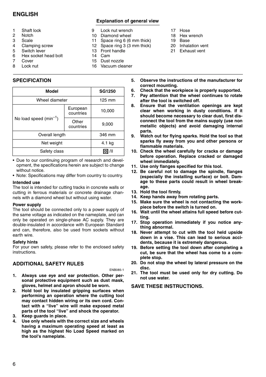
Explanation of general view
1 Shaft lock
2 Notch
3 Scale
4 Clamping screw
5 Switch lever
6 Hex socket head bolt
7 Cover
8 Lock nut
9 Lock nut wrench
10 Diamond wheel
11 Space ring 6 (6 mm thick)
12 Space ring 3 (3 mm thick)
13 Front handle
14 Cam
15 Dust nozzle
16 Vacuum cleaner
17 Hose
18 Hex wrench
19 Base
20 Inhalation vent
21 Exhaust vent
SPECIFICATION
| Model | SG1250 | |
| Wheel diameter | 125 mm | |
| No load speed (min-1) | European countries | 10,000 |
| Other countries | 9,000 | |
| Overall length | 346 mm | |
| Net weight | 4.1 kg | |
| Safety class | ☐/II | |
- Due to our continuing program of research and development, the specifications herein are subject to change without notice.
- Note: Specifications may differ from country to country.
Intended use
The tool is intended for cutting tracks in concrete walls or cutting in ferrous materials or concrete drainage channels with a diamond wheel but without using water.
Power supply
The tool should be connected only to a power supply of the same voltage as indicated on the nameplate, and can only be operated on single-phase AC supply. They are double-insulated in accordance with European Standard and can, therefore, also be used from sockets without earth wire.
Safety hints
For your own safety, please refer to the enclosed safety instructions.
ADDITIONAL SAFETY RULES
ENB085-1
- Always use eye and ear protection. Other personal protective equipment such as dust mask, gloves, helmet and apron should be worn.
- Hold tool by insulated gripping surfaces when performing an operation where the cutting tool may contact hidden wiring or its own cord. Contact with a "live" wire will make exposed metal parts of the tool "live" and shock the operator.
- Keep guards in place.
-
Use only wheels with the correct size and wheels having a maximum operating speed at least as high as the highest No Load Speed marked on the tool's nameplate.
-
Observe the instructions of the manufacturer for correct mounting.
- Check that the workpiece is properly supported.
- Pay attention that the wheel continues to rotate after the tool is switched off.
- Ensure that the ventilation openings are kept clear when working in dusty conditions. If it should become necessary to clear dust, first disconnect the tool from the mains supply (use non metallic objects) and avoid damaging internal parts.
- Watch out for flying sparks. Hold the tool so that sparks fly away from you and other persons or flammable materials.
- Check the wheel carefully for cracks or damage before operation. Replace cracked or damaged wheel immediately.
- Use only flanges specified for this tool.
- Be careful not to damage the spindle, flanges (especially the installing surface) or bolt. Damage to these parts could result in wheel breakage.
- Hold the tool firmly.
- Keep hands away from rotating parts.
- Make sure the wheel is not contacting the workpiece before the switch is turned on.
- Wait until the wheel attains full speed before cutting.
- Stop operation immediately if you notice anything abnormal.
- Never attempt to cut with the tool held upside down in a vise. This can lead to serious accidents, because it is extremely dangerous.
- Before setting the tool down after completing a cut, be sure that the wheel has come to a complete stop.
- Do not stop the wheel by lateral pressure on the disc.
- The tool must be used only for dry cutting. Do not use water.
SAVE THESE INSTRUCTIONS.
FUNCTIONAL DESCRIPTION
CAUTION:
Always be sure that the tool is switched off and unplugged before adjusting or checking function on the tool.
Shaft lock (Fig. 1)
CAUTION:
- Never actuate the shaft lock when the spindle is moving. The tool may be damaged.
Press the shaft lock to prevent spindle rotation when installing or removing accessories.
Sightng (Fig. 2)
There are notches on the front and rear of the base. This is helpful for an operator to follow a straight cutting line.
Adjusting the grooving or cutting depth (Fig. 3)
The depth of grooving or cutting can be adjusted in the range of 0 through 30mm
Loosen and move the clamping screw so that the pointer points to your desired depth graduation on the scale.
Then tighten the clamping screw firmly.
Switch action (Fig. 4)
CAUTION:
- Before plugging in the tool, always check to see that the slide switch actuates properly and returns to the "OFF" position when the rear of the slide switch is depressed.
To start the tool, slide the slide switch toward the "I (ON)" position. For continuous operation, press the front of the slide switch to lock it.
To stop the tool, press the rear of the slide switch, then slide it toward the "O (OFF)" position.
Electronic function
The tools equipped with electronic function are easy to operate because of the following features.
Constant speed control
Electronic speed control for obtaining constant speed. Possible to get fine finish, because the rotating speed is kept constant even under load condition.
Soft start
Soft-start feature minimizes start-up shock, and makes the tool start smoothly.
Overload protector
When the tool would be employed over the admissible load, it will stop automatically to protect the motor and wheel. When the load will come to the admissible level again, the tool can be started automatically.
ASSEMBLY
CAUTION:
Always be sure that the tool is switched off and unplugged before carrying out any work on the tool.
Installing or removing the diamond wheel
Removal (Fig. 5, 6 & 7)
Loosen and remove the bolt with the hex wrench.
Open the cover while holding the tool base with a hand as shown in the figure.
NOTE:
- The tool base will open at a stroke by the spring force.
Rotate the diamond wheel while pressing the shaft lock until it engages.
Remove the lock nut by rotating it counterclockwise with the lock nut wrench.
Remove the diamond wheel and space rings.
Adjusting the groove width (the distance between the two diamond wheels)
The width of grooving in the workpiece can be adjusted by changing the number of the space rings as shown in the table. (Fig. 8)
Installation (Fig. 9)
Determine the distance of the two blades according to the table.
To install the diamond wheel, mount it carefully onto the spindle, making sure that the direction of the arrow on the surface of the diamond wheel matches the direction of the arrow on the tool. Install space ring and lock nut.
Tighten the lock nut securely clockwise with the lock nut wrench while pushing down the shaft lock.
Return the cover and the base to the original position and tighten the bolt to secure them.
Front handle (Fig. 10 & 11)
The angle of installation of the front handle is changeable.
To change its position, loosen the two bolts on both sides of the front handle with the hex wrench and move the front handle to your desired position.
NOTE:
- When the handle cannot be moved easily, loosen the bolts furthermore.
To secure the handle, tighten the two bolts firmly.
The front handle can be shifted sideways.
To shift it, loosen and remove the two bolts on both sides of the front handle.
Remove the cam and install it on the opposite side as shown in the figure.
Insert the longer bolt to the hole in the handle on the side close to the installed cam and the shorter bolt on the opposite side.
Then tighten the two bolts firmly.
Connecting to vacuum cleaner (Fig. 12)
When you wish to perform cleaner operation, connect a vacuum cleaner to your tool. Connect a hose of vacuum cleaner to the dust nozzle.
NOTE:
- The dust nozzle can be rotated freely so that you can use it at any angle according to your operation.
Hex wrench storage (Fig. 13)
When not in use, store the hex wrench as shown in the figure to keep it from being lost.
OPERATION
CAUTION:
- Be sure to pull the tool when cutting a workpiece.
- Use this tool for straight line cutting only. Cutting curves can cause stress cracks or fragmentation of the diamond wheel resulting in possible injury to persons in the vicinity.
- After operation, always switch off the tool and wait until the wheel has come to a complete stop before putting the tool down.
- Always use the front grip and firmly hold the tool by both front grip and main handle during operations.
Adjust the front handle to appropriate position for your work by referring to the "Front handle" in the section "ASSEMBLY".
Hold the tool firmly with both hands. First keep the wheel without making any contact with a workpiece to be cut. Then turn the tool on and wait until the wheel attains full speed.
The cut is made by pulling the tool toward you (not by pushing away from you). Align the notch on the base with your cutting line, push down the front handle gently until it stops and then pull the tool slowly to perform a cut. (Fig. 14)
Switch off the tool in the position posed when finishing a cut. Raise the tool after the wheel comes to a complete stop.
Remove the remaining portion between the two blade passage by other appropriate tools.
MAINTENANCE
CAUTION:
Always be sure that the tool is switched off and unplugged before attempting to perform inspection or maintenance.
The tool and its air vents have to be kept clean. Regularly clean the tool's air vents or whenever the vents start to become obstructed. (Fig. 15)
Dressing diamond wheel
If the cutting action of the diamond wheel begins to diminish, use an old discarded coarse grit bench grinder wheel or concrete block to dress the diamond wheel. To do this, tightly secure the bench grinder wheel or concrete block and cut in it.
To maintain product SAFETY and RELIABILITY, repairs, carbon brush inspection and replacement, any other maintenance or adjustment should be performed by Makita Authorized Service Centers, always using Makita replacement parts.
ACCESSORIES
CAUTION:
- These accessories or attachments are recommended for use with your Makita tool specified in this manual. The use of any other accessories or attachments might present a risk of injury to persons. Only use accessory or attachment for its stated purpose.
If you need any assistance for more details regarding these accessories, ask your local Makita service center.
Diamond wheels
Descriptif
EC-DECLARATION OF CONFORMITY
We declare under our sole responsibility that this product is in compliance with the following standards of standardized documents, HD400, EN50144, EN55014, EN61000
in accordance with Council Directives, 73/23/EEC, 89/336/EEC and 98/37/EC.
FRANÇAISE
DECLARATION DE CONFORMITE CE
HD400, EN50144, EN55014, EN61000.
ITALIANO
de accordo com as directivas 73/23/CEE, 89/336/CEE e 98/37/CE do Conselho.
DANSK
EU-DEKLARATION OM KONFORMITET
Michigan Drive, Tongwell, Milton Keynes,
Bucks MK15 8JD, ENGLAND
ENGLISH
Noise and Vibration
The typical A-weighted noise levels are
sound pressure level: 98 dB (A)
sound power level: 111 dB (A)
- Wear ear protection. -
The typical weighted root mean square acceleration value is not more than 2.5m / s^2
FRANÇAISE
Bruit et vibrations


- Symboles
- Explanation of general view
- Intended use
- Power supply
- Safety hints
- ADDITIONAL SAFETY RULES
- SAVE THESE INSTRUCTIONS.
- FUNCTIONAL DESCRIPTION
- CAUTION:
- Shaft lock (Fig. 1)
- Sightng (Fig. 2)
- Adjusting the grooving or cutting depth (Fig. 3)
- Switch action (Fig. 4)
- Electronic function
- Constant speed control
- Soft start
- Overload protector
- ASSEMBLY
- Installing or removing the diamond wheel
- Removal (Fig. 5, 6 & 7)
- NOTE:
- Adjusting the groove width (the distance between the two diamond wheels)
- Installation (Fig. 9)
- Front handle (Fig. 10 & 11)
- Connecting to vacuum cleaner (Fig. 12)
- Hex wrench storage (Fig. 13)
- OPERATION
- MAINTENANCE
- Dressing diamond wheel
- ACCESSORIES
- Descriptif
- EC-DECLARATION OF CONFORMITY
- FRANÇAISE
- DECLARATION DE CONFORMITE CE
- ITALIANO
- DANSK
- EU-DEKLARATION OM KONFORMITET
- ENGLISH
- Noise and Vibration
- Bruit et vibrations
Brand : MAKITA
Model : SG1250
Category : Grinders