
LC1230 - Cold saw MAKITA - Free user manual and instructions
Find the device manual for free LC1230 MAKITA in PDF.

User questions about LC1230 MAKITA
0 question about this device. Answer the ones you know or ask your own.
Ask a new question about this device
Download the instructions for your Cold saw in PDF format for free! Find your manual LC1230 - MAKITA and take your electronic device back in hand. On this page are published all the documents necessary for the use of your device. LC1230 by MAKITA.
USER MANUAL LC1230 MAKITA
natural_image
Technical line drawing of a mechanical cutting tool with a base and mounting bracket (no text or symbols)
1
2
3
4
5
6
7
8
natural_image
Technical line drawing of a mechanical assembly with spring, handle, and hanging hook (no text or symbols)9
10
11
12
natural_image
Pure mechanical diagram showing a shaft and housing with a curved arrow indicating motion (no text or symbols)13
14
15
16
17
18
19
20
Symbols
The following show the symbols used for the tol. Be sure that you understand their meaning before use.
Symboles
☐ To avoid injury from flying debris, keep holding the saw head down, after making cuts, until the blade has come to a complete stop.
☐ For your safety, remove the chips, small pieces, etc. from the table top before operation.
Explanation of general view
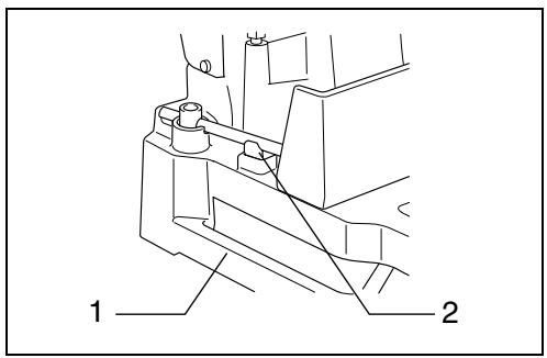
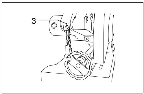
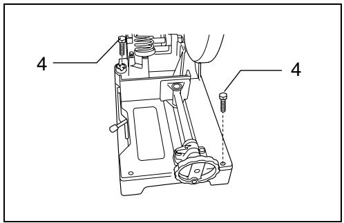
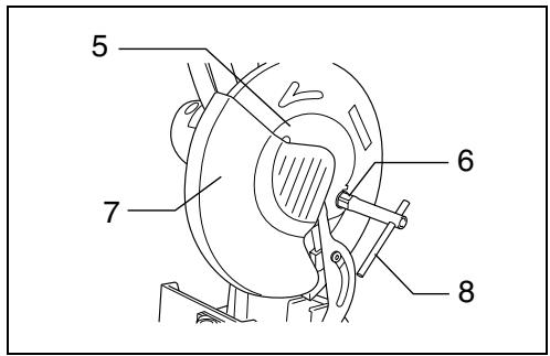
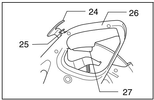
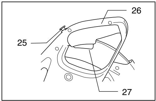
| 1 | Base | 12 | Inner flange | 23 | Vise handle |
| 2 | Wrench holder | 13 | Carbide-tipped saw blade | 24 | Lever |
| 3 | Hook | 14 | Outer flange | 25 | Lock-off button |
| 4 | Bolt | 15 | Lever | 26 | Handle |
| 5 | Center cover | 16 | Loosen | 27 | Switch trigger |
| 6 | Hex bolt | 17 | Tighten | 28 | Dust box |
| 7 | Safety cover (Safety guard) | 18 | Vise stop | 29 | Limit mark |
| 8 | Socket wrench | 19 | Indicator | 30 | Screwdriver |
| 9 | Shaft lock | 20 | Graduation | 31 | Brush holder cap |
| 10 | Hex bolt | 21 | Vise plate | ||
| 11 | Spindle | 22 | Vise nut |
SPECIFICATIONS
| Model | LC1230 |
| Blade diameter | 305 mm |
| Hole (arbor) diameter | 25.4 mm |
| No load speed ( min^-1 ) | 1,300 |
| Dimensions (L x W x H) | 516 mm x 306 mm x 603 mm |
| Net weight | 19.0 kg |
Cutting capacity
| Cutting angle\Workpiece shape |  | A x R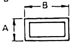 |
| 90° | 115 mm | 75 mm x 150 mm100 mm x 100 mm |
| 45° | 90 mm | 85 mm x 85 mm |
- Due to our continuing program of research and development, the specifications herein are subject to change without notice.
- Note: Specifications may differ from country to country.
Intended use
The tool is intended for cutting in mild steel and stainless steel with appropriate saw blades.
Power supply
The tool should be connected only to a power supply of the same voltage as indicated on the nameplate, and can only be operated on single-phase AC supply. They are double-insulated in accordance with European Standard and can, therefore, also be used from sockets without earth wire.
For public low-voltage distribution systems of between 220 V and 250 V
Switching operations of electric apparatus cause voltage fluctuations. The operation of this device under unfavorable mains conditions can have adverse effects to the operation of other equipment. With a mains impedance equal or less than 0.25 Ohms it can be presumed that there will be no negative effects.
The mains socket used for this device must be protected with a fuse or protective circuit breaker having slow tripping characteristics.
Safety hints
For your own safety, please refer to the enclosed safety instructions.
ADDITIONAL SAFETY RULES
- Always use safety glasses, dust mask and ear protector.
- Use only Makita genuine carbide-tipped saw blade 305 mm in diameter for metal cutting. Never use abrasive cut-off wheel or other type of saw blades.
- Check the blade carefully for cracks or damage before operation. Replace cracked or damaged blade immediately.
- Never secure the safety cover (safety guard). Always be sure that the safety cover moves smoothly before operation. Any irregular operation of the safety cover should be corrected immediately.
Do not use the saw without guards in position. - Be sure shaft lock is released before the switch is turned on.
- Before using the tool on an actual workpiece, let it run for a while. Watch for vibration or wobbling that could indicate poor installation or a poorly balanced blade.
- Keep your hands and body away from rotating blade.
- Always secure the workpiece with the vise.
-
Make sure the blade is not contacting the workpiece before the switch is turned on.
-
Watch out for flying sparks when operating. They can cause injury or ignite combustible materials.
- Do not touch the blade, workpiece or cutting chips immediately after operation; they may be extremely hot and could burn your skin.
- If the blade stops during operation, makes an odd noise or begins to vibrate, switch off the tool immediately. Then check the tool and blade.
SAVE THESE INSTRUCTIONS.
OPERATING INSTRUCTIONS
Socket wrench (Fig. 1)
The socket wrench is stored on the left side of the tool base. When using the socket wrench, pull it out of the wrench holder. After using the socket wrench, return it to wrench holder.
Positioning the tool
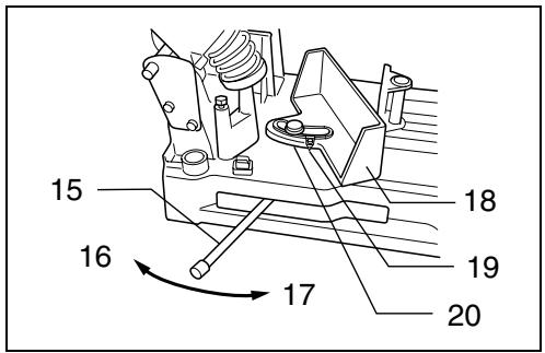
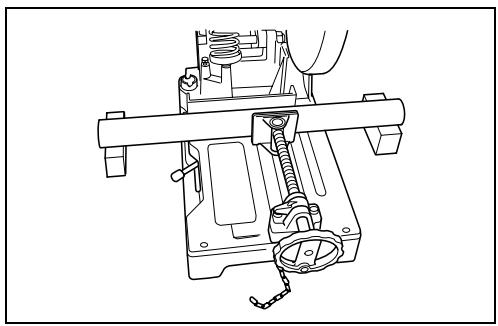
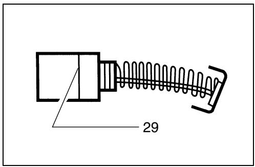
When the tool is shipped from the factory, the handle is locked in the lowered position. Release the handle from the lowered position by lowering it slightly and removing the chain from the hook on the handle. (Fig. 2)
Bolt the tool with two bolts to a level and stable surface using the bolt holes provided in the tool base. This will help prevent tipping and possible injury. (Fig. 3)
Removing or installing saw blade
CAUTION:
- Always be sure that the tool is switched off and unplugged before removing or installing the blade.
- When mounting the blade, make sure that the direction of the arrow on the surface of the blade matches the direction of the arrow on the blade case.
- Use only the Makita socket wrench provided to install or remove the blade. Failure to do so may result in overtightening or insufficient tightening of the hex bolt. This could cause serious injury to operator or others in the general vicinity of the tool.
- Do not touch the blade immediately after operation; it may be extremely hot and could burn your skin.
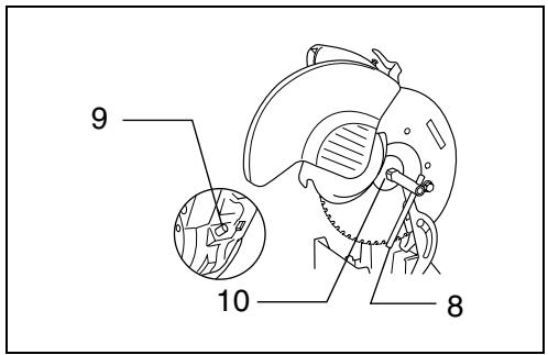
To remove the blade, loosen the hex bolt holding the center cover with the socket wrench. Raise the safety cover (safety guard) and center cover. (Fig. 4)
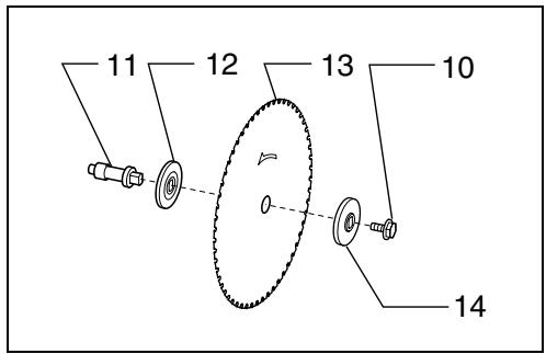
Press the shaft lock to lock the spindle and use the socket wrench to loosen the hex bolt by turning counterclockwise. Then remove the hex bolt, outer flange and blade. (Fig. 5)
To install the blade, mount the inner flange, saw blade, outer flange and hex bolt onto the spindle in that order. Tighten the hex bolt by turning clockwise while pressing the shaft lock. Return the safety cover and center cover to the original position. Then tighten the hex bolt clockwise to secure the center cover. Lower the handle to make sure that the safety cover moves properly. (Fig. 6)
Setting for desired cutting angle (Fig. 7)
CAUTION:
Always tighten the hex bolt securely after changing the cutting angle.
To change the cutting angle, loosen the lever. Move the vise stop so that the indicator will point to the desired graduation. Then tighten the lever to secure the vise stop.
Securing workpieces
CAUTION:
Always set the vise nut to the right fully when securing the workpiece. Failure to do so may result in insufficient securing of the workpiece. This could cause the workpiece to be ejected or cause damage to the blade.
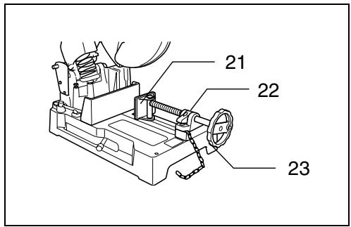
By turning the vise handle counterclockwise and then flipping the vise nut to the left, the vise is released from the shaft threads and can be moved rapidly in and out. To grip workpieces, push the vise handle until the vise plate contacts the workpiece. Flip the vise nut to the right and then turn the vise handle clockwise to securely retain the workpiece. (Fig. 8)
Long workpieces must be supported by blocks of non-flammable material on either side so that it will be level with the base top. (Fig. 9)
Switch action
CAUTION:
- Before plugging in the tool, always check to see that the switch trigger actuates properly and returns to the "OFF" position when released.
- When not using the tool, remove the lock-off button and store it in a secure place. This prevents unauthorized operation.
For European countries (Fig. 10)
To prevent the trigger from being accidentally pulled, a lock-off button is provided. To start the tool, depress the lever to release the handle from the fully elevated position and to press in the lock-off button, and then pull the trigger. Release the trigger to stop.
For all countries other than European countries (Fig. 11)
To prevent the trigger from being accidentally pulled, a lock-off button is provided. To start the tool, press in the lock-off button and pull the trigger. Release the trigger to stop.
Cutting operation
CAUTION:
- Never attempt to cut workpieces less than 2 mm thick except pipe or workpieces which cannot be secured firmly with the vise. The piece cut off may be caught by the blade, causing dangerous scattering of chips and/or damage to the carbide-tips. Possible serious injury may result.
- Do not apply excessive pressure on the handle when cutting. Too much pressure may result in overload of the motor, decreased cutting efficiency and/or damage to the carbide-tips or blade itself.
- Too little pressure on the handle may result in more sparks and premature blade wear.
- Do not touch the blade, workpiece or cutting chips immediately after operation; they may be extremely hot and could burn your skin.
- If the blade stops during operation, makes an odd noise or begins to vibrate, switch off the tool immediately. Replace cracked or damaged blade with a new one.
- Do not cut aluminum, wood, plastics, concrete, tiles, etc.
- Always use carbide-tipped saw blades appropriate for your job. The use of inappropriate saw blades may cause a poor cutting performance and/or present a risk of personal injury.
Recommended Carbide-tipped saw blade & workpiece ranges
| Diameter & number of teeth | Application | Applicable workpiece & thickness range | ||||
| Angles | Metal Pipes | Channels | Stainless Pipes | Stainless Angles | ||
| 305 * 60 | Mild Steel | 4 mm or more | 3–5 mm | 4 mm or more | NA | NA |
| 305 * 60 | Mild Steel (Lessened Noise Type) | 4 mm or more | 3–5 mm | 4 mm or more | NA | NA |
| 305 * 78 | Thin Mild Steel | 3–6 mm | 1.2–5 mm | 2 mm or more | NA | NA |
| 305 * 78 | Stainless | 3–6 mm | 1.2–5 mm | 4 mm or more | 1.2–5 mm | 3–4 mm |
(NA ... Not applicable)
- Standard blade may differ from country to country.
- Carbide-tipped saw blades for metal cutting saw are not to be re-sharpened.
Hold the handle firmly. Switch on the tool and wait until the blade attains full speed. Then lower the handle gently to bring the blade close to the workpiece. When the blade makes contact, ease into the cut gently at first, then gradually add pressure as the cutting position steadies. Your pressure on the handle should be adjusted to produce the minimum amount of sparks.
When the cut is completed, switch off the tool and WAIT UNTIL THE BLADE HAS COME TO A COMPLETE STOP before returning the handle to the fully elevated position. If the handle is raised while the blade is still rotating, the piece cut off may be caught by the blade, causing dangerous scattering of chips. When cutting only part of the way into a workpiece, raise the handle while the blade is rotating. Switching off during the cut may cause damage to the carbide-tips as they contact the workpiece.
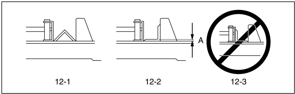
Cutting angles (Figs. 12 & 13)
Secure the workpiece in the vise as shown in Fig. 12-1, and proceed to cut it. The saw blade life will be shortened if the workpiece is cut as shown in Fig. 12-2.
CAUTION:
Do NOT cut the workpiece as shown in Fig. 12-3 since this may cause it to be ejected from the vise, possibly resulting in injury.
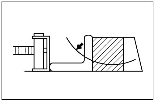
The saw blade is subjected to greater wear when the area A in Fig. 12-2 is cut. Place a wooden block up against the workpiece as shown in Fig. 13 so that the saw blade will enter area A at an angle. This will help to extend the saw blade life.
The allowable cutting dimensions are reduced when a wooden block is used. Use a wooden block whose dimensions are equivalent to the maximum allowable cutting dimensions minus the dimensions of the workpiece to be cut. This will further minimize the shortening of the saw blade life.
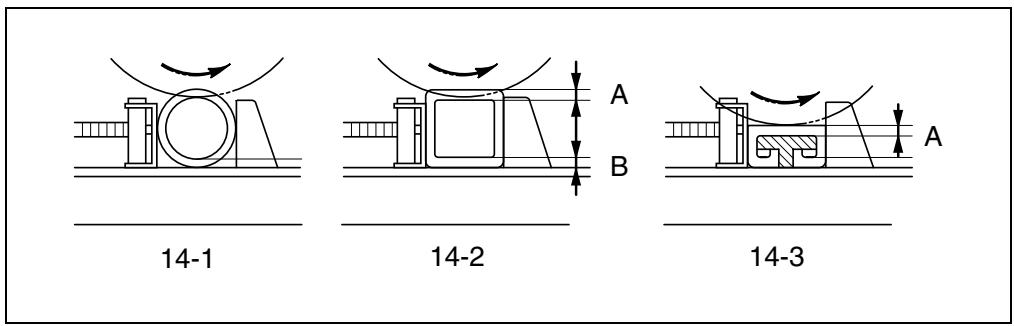
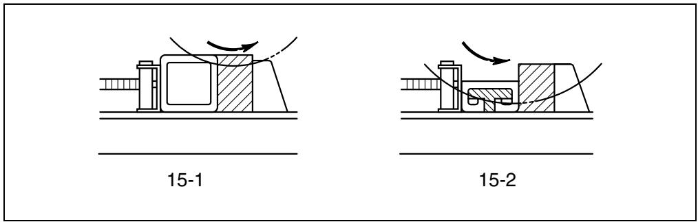
Cutting pipes, squares and channels (Figs. 14 & 15)
The saw blade is subjected to greater wear when the areas A and B in Figs. 14-2 and 14-3 are cut. Place a wooden block up against the workpiece as shown in Fig. 15-2 so that the saw blade will enter areas A and B at an angle. This will help to minimize the shortening of the saw blade life.
The allowable cutting dimensions are reduced when a wooden block is used. Use a wooden block whose dimensions are equivalent to the maximum allowable cutting dimensions minus the dimensions of the workpiece to be cut. This will further minimize the shortening of the saw blade life.
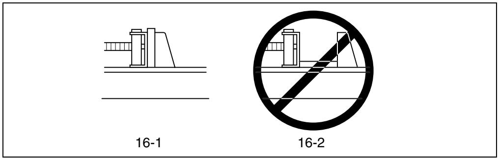
Cutting rectangles (Fig. 16)
Secure the workpiece in the vise as shown in Fig. 16-1, and proceed to cut it.
CAUTION:
Do NOT cut the workpiece as shown in Fig. 16-2 since this may cause it to be ejected from the vise, possibly resulting in injury.
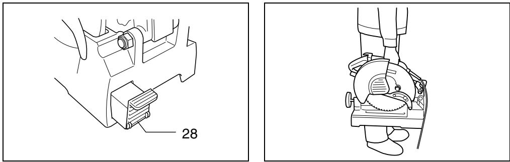
Dust collection (Fig. 17)
CAUTION:
Do not touch any part of the dust box except its handle immediately after operation; it may be extremely hot and could burn your skin.
This tool is equipped with the dust box to collect dust and cut chips. When the dust box is full, hold the handle of the dust box and raise it slightly. Then pull the dust box out of the tool base. Empty the dust box of its contents.
Carrying the tool (Fig. 18)
CAUTION:
The chain for transportation shall be adjusted to minimize the accessible zone of the saw blade before transporting the tool.
Fold down the tool head to the position where you can attach the chain to the hook on the handle. Grasp the carrying grip when carrying the tool.
MAINTENANCE
CAUTION:
Always be sure that the tool is switched off and unplugged before carrying out any work on the tool.
Replacing saw blade
Continuing to use a dull and worn blade may cause motor overload and decreased cutting efficiency. Replace with a new blade as soon as it is no longer effective.
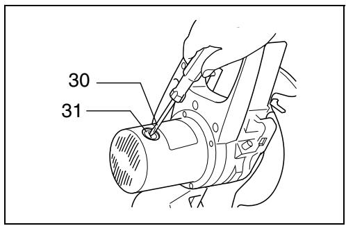
Replacement of carbon brushes (Fig. 19 & 20)
Replace carbon brushes when they are worn down to the limit mark. Both identical carbon brushes should be replaced at the same time.
To maintain product safety and reliability, repairs, maintenance or adjustment should be carried out by a Makita Authorized Service Center.
Descriptif
These accessories or attachments are recommended for use with your Makita tool specified in this manual. The use of any other accessories or attachments might present a risk of injury to persons. The accessories or attachments should be used only in the proper and intended manner.
F ACCESSOIRES
ATTENTION :
EC-DECLARATION OF CONFORMITY
We declare under our sole responsibility that this product is in compliance with the following standards or standardized documents,
EN61029, EN55014, EN61000
in accordance with Council Directives, 73/23/EEC, 89/336/EEC and 98/37/EC.
FRANÇAISE
DÉCLARATION DE CONFORMITÉ CE
Michigan Drive, Tongwell, Milton Keynes, Bucks MK15 8JD, ENGLAND
PORTUGUÊS
EU-DEKLARATION OM KONFORMITET
Michigan Drive, Tongwell, Milton Keynes, Bucks MK15 8JD, ENGLAND
ENGLISH
Noise and Vibration
The typical A-weighted noise levels are
sound pressure level: 98 dB (A)
sound power level: 111 dB (A)
- Wear ear protection. -
The typical weighted root mean square acceleration value is not more than 2.5 m/s^2 .
FRANÇAISE
Bruit et vibrations
Tuck & Co (Ireland) LTD
77 Upper Gardiner street.
DUBLIN 1, Ireland
Phone: 00 353 1 8749851
ITALY
Makita S.p.A.
Via Sempione 269A,
28820 COSLADA (MADRID)
Tfno.: 671 1262
Fax.: 671 8293
SWEDEN
ESSVE Produkter AB
Box 770
Sidensvansvägen 10
19127 Sollentuna
Tel vxl: 08-623 61 00
Fax: 08-92 68 65
SWITZERLAND
Hebor SA
Route de Genges 6
Z.I. En Carouge
CH-1027 LONAY/Morges
Tél.: 021/803 07 51
Michigan Drive, Tongwell,
Milton Keynes,
Bucks MK15 8JD
Phone: (01908) 211678
Fax: (01908) 211400
Makita Corporation Japan
- Symbols
- Symboles
- Intended use
- Power supply
- For public low-voltage distribution systems of between 220 V and 250 V
- Safety hints
- ADDITIONAL SAFETY RULES
- SAVE THESE INSTRUCTIONS.
- OPERATING INSTRUCTIONS
- Socket wrench (Fig. 1)
- Positioning the tool
- Removing or installing saw blade
- CAUTION:
- Setting for desired cutting angle (Fig. 7)
- Securing workpieces
- Switch action
- For European countries (Fig. 10)
- For all countries other than European countries (Fig. 11)
- Cutting operation
- Cutting angles (Figs. 12 & 13)
- Cutting pipes, squares and channels (Figs. 14 & 15)
- Cutting rectangles (Fig. 16)
- Dust collection (Fig. 17)
- Carrying the tool (Fig. 18)
- MAINTENANCE
- Replacing saw blade
- Replacement of carbon brushes (Fig. 19 & 20)
- F ACCESSOIRES
- ATTENTION :
- EC-DECLARATION OF CONFORMITY
- FRANÇAISE
- DÉCLARATION DE CONFORMITÉ CE
- PORTUGUÊS
- EU-DEKLARATION OM KONFORMITET
- ENGLISH
- Noise and Vibration
- Bruit et vibrations
- ITALY
- SWEDEN
- SWITZERLAND
- Makita Corporation Japan
Brand : MAKITA
Model : LC1230
Category : Cold saw