3612C - Router MAKITA - Free user manual and instructions
Find the device manual for free 3612C MAKITA in PDF.
| Product type | Electronic router |
| Brand | Makita |
| Model | 3612C |
| Clamping capacity (collet) | 12 mm |
| Plunge depth | 0 - 60 mm |
| No-load speed | 9,000 - 23,000 rpm (electronically variable) |
| Overall height | 297 mm |
| Base diameter | 160 mm |
| Net weight | 6.0 kg |
| Power supply | 220-250 V, single-phase, 50/60 Hz |
| Double insulation | Yes |
| Electrical protection | Fuse or slow-blow circuit breaker (impedance ≤0.32 Ω) |
| Straight guide | Included |
| Jointer guide | Included |
| Template guide | Included |
| Vacuum head | Included (for models with locking plate) |
| Switch | With lock-off button and trigger |
| Sound level | 81 dB(A) |
| Vibration level | ≤ 2.5 m/s² |
| Certifications | CE (standards HD400, EN50144, EN55014, EN61000) |
Frequently Asked Questions - 3612C MAKITA
User questions about 3612C MAKITA
0 question about this device. Answer the ones you know or ask your own.
Ask a new question about this device
Download the instructions for your Router in PDF format for free! Find your manual 3612C - MAKITA and take your electronic device back in hand. On this page are published all the documents necessary for the use of your device. 3612C by MAKITA.
USER MANUAL 3612C MAKITA
The following show the symbols used for the machine. Be sure that you understand their meaning before use.
Symboles
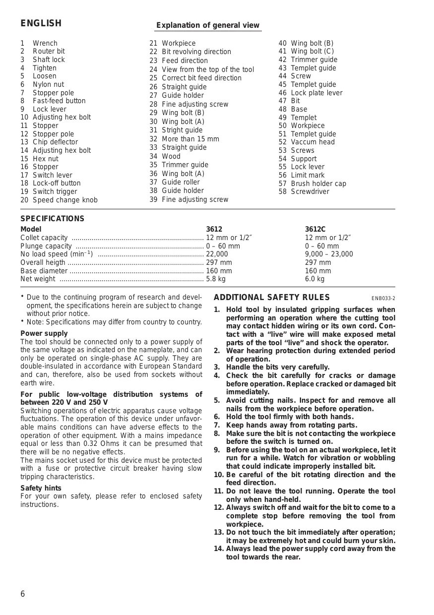
Explanation of general view
| 1 | Wrench | 21 | Workpiece | 40 | Wing bolt (B) |
| 2 | Router bit | 22 | Bit revolving direction | 41 | Wing bolt (C) |
| 3 | Shaft lock | 23 | Feed direction | 42 | Trimmer guide |
| 4 | Tighten | 24 | View from the top of the tool | 43 | Templet guide |
| 5 | Loosen | 25 | Correct bit feed direction | 44 | Screw |
| 6 | Nylon nut | 26 | Straight guide | 45 | Templet guide |
| 7 | Stopper pole | 27 | Guide holder | 46 | Lock plate lever |
| 8 | Fast-feed button | 28 | Fine adjusting screw | 47 | Bit |
| 9 | Lock lever | 29 | Wing bolt (B) | 48 | Base |
| 10 | Adjusting hex bolt | 30 | Wing bolt (A) | 49 | Templet |
| 11 | Stopper | 31 | Stright guide | 50 | Workpiece |
| 12 | Stopper pole | 32 | More than 15 mm | 51 | Templet guide |
| 13 | Chip deflector | 33 | Straight guide | 52 | Vacum head |
| 14 | Adjusting hex bolt | 34 | Wood | 53 | Screws |
| 15 | Hex nut | 35 | Trimmer guide | 54 | Support |
| 16 | Stopper | 36 | Wing bolt (A) | 55 | Lock lever |
| 17 | Switch lever | 37 | Guide roller | 56 | Limit mark |
| 18 | Lock-off button | 38 | Guide holder | 57 | Brush holder cap |
| 19 | Switch trigger | 39 | Fine adjusting screw | 58 | Screwdriver |
| 20 | Speed change knob |
SPECIFICATIONS
| Model | 3612 | 3612C |
| Collet capacity | 12 mm or 1/2" | 12 mm or 1/2" |
| Plunge capacity | 0 - 60 mm | 0 - 60 mm |
| No load speed (min-1) | 22,000 | 9,000 - 23,000 |
| Overall heigth | 297 mm | 297 mm |
| Base diameter | 160 mm | 160 mm |
| Net weight | 5.8 kg | 6.0 kg |
- Due to the continuing program of research and development, the specifications herein are subject to change without prior notice.
- Note: Specifications may differ from country to country.
Power supply
The tool should be connected only to a power supply of the same voltage as indicated on the nameplate, and can only be operated on single-phase AC supply. They are double-insulated in accordance with European Standard and can, therefore, also be used from sockets without earth wire.
For public low-voltage distribution systems of between 220 V and 250 V
Switching operations of electric apparatus cause voltage fluctuations. The operation of this device under unfavorable mains conditions can have adverse effects to the operation of other equipment. With a mains impedance equal or less than 0.32 Ohms it can be presumed that there will be no negative effects.
The mains socket used for this device must be protected with a fuse or protective circuit breaker having slow tripping characteristics.
Safety hints
For your own safety, please refer to enclosed safety instructions.
ADDITIONAL SAFETY RULES
ENB033-2
- Hold tool by insulated gripping surfaces when performing an operation where the cutting tool may contact hidden wiring or its own cord. Contact with a "live" wire will make exposed metal parts of the tool "live" and shock the operator.
- Wear hearing protection during extended period of operation.
- Handle the bits very carefully.
- Check the bit carefully for cracks or damage before operation. Replace cracked or damaged bit immediately.
- Avoid cutting nails. Inspect for and remove all nails from the workpiece before operation.
- Hold the tool firmly with both hands.
- Keep hands away from rotating parts.
- Make sure the bit is not contacting the workpiece before the switch is turned on.
- Before using the tool on an actual workpiece, let it run for a while. Watch for vibration or wobbling that could indicate improperly installed bit.
- Be careful of the bit rotating direction and the feed direction.
- Do not leave the tool running. Operate the tool only when hand-held.
- Always switch off and wait for the bit to come to a complete stop before removing the tool from workpiece.
- Do not touch the bit immediately after operation; it may be extremely hot and could burn your skin.
-
Always lead the power supply cord away from the tool towards the rear.
-
Do not smear the tool base carelessly with thinner, gasoline, oil or the like.
They may cause cracks in the tool base. - Draw attention to the need to use cutters of the correct shank diameter and which are suitable for the speed of the tool.
SAVE THESE INSTRUCTIONS.
OPERATING INSTRUCTIONS
Installing or removing the router bit (Fig. 1)
Important:
Always be sure that the tool is switched off and unplugged from the supply outlet before installing or removing the router bit.
Insert the router bit all the way into the collet. Press the shaft lock to keep the shaft stationary and use the wrench to tighten the collet nut securely. When using router bits with smaller shank diameter, first mount the appropriate collet, then install the bit as described above.
CAUTION:
- Do not tighten the collet without inserting a router bit.
- Use always a collet which is suitable for the shank diameter of the router bit.
- Use only router bits of which the maximum speed, as indicated on the bit, does exceed the maximum speed of the router.
Adjusting the depth of cut (Fig. 2)
Important:
Always be sure that the tool is switched off and unplugged before adjusting the depth of cut.
Place the tool on a flat surface. Loosen the lock lever and lower the tool body until the bit just touches the flat surface. Press the lock lever down to lock the tool body. While pressing the fast-feed button, move the stopper pole up or down until the desired depth of cut is obtained. Minute depth adjustments can be obtained by turning the stopper pole (1.5 mm per turn).
CAUTION:
The depth of cut should not be more than 20mm at a pass when cutting grooves. For extra-deep grooving operations, make two or three passes with progressively deeper bit settings.
Nylon nut (Fig. 2)
The upper limit of the tool body can be adjusted by turning the nylon nut. Do not lower the nylon nut too low. The bit will protrude dangerously.
Stopper (Fig. 3)
As the rotary stopper has three adjusting hex bolts, you can easily obtain three different depths of cut without readjusting the stopper pole. To adjust the hex bolts, loosen the hex nuts on them and turn the hex bolts. After obtaining the desired position, tighten the hex nuts to secure the hex bolts.
Switching ON and OFF
For tool without lock-off button (Fig. 4)
CAUTION:
Make sure that the shaft lock is released before the switch is turned on.
To switch on, move the switch lever to the "ON" position.
To switch off, move the switch lever to the "OFF" position.
For tool with lock-off button (Fig. 5)
CAUTION:
- Before plugging in the tool, always check to see that the switch trigger actuates properly and returns to the "OFF" position when released.
- Make sure that the shaft lock is released before the switch is turned on.
To switch on, push the lock-off button and at the same time press the trigger.
To switch off, release the trigger.
Speed change knob (Fig. 6)
For 3612C only
The tool speed can be infinitely adjusted between 9,000 rpm and 23,000 rpm by turning the speed change knob. This allows the ideal speed to be selected for optimum material processing, i.e. the speed can be correctly adjusted to suit the material and bit diameter. Refer to the table below for relationship between the number settings on the speed change knob and approx. tool speed.
| Number | RPM |
| 1 | 9,000 |
| 2 | 12,000 |
| 3 | 15,000 |
| 4 | 19,000 |
| 5 | 23,000 |
Operation (Fig. 7)
Place the tool on the workpiece and switch on. Release the lock lever and slowly lower the tool onto the workpiece until preset routing depth is reached. Move the tool forward using both hands. When cutting edges, the workpiece surface should be on the left side of the bit in the feed direction as shown in Fig. 7.
Straight guide
When using the straight guide, be sure to install it on the right side in the feed direction. (Fig. 8)
Install the straight guide on the guide holder with the wing bolt (B). Insert the guide holder into the holes in the tool base and tighten the wing bolt (A). To adjust the distance between the bit and the straight guide, loosen the wing bolt (B) and turn the fine adjusting screw (1.5 mm per turn). (Fig. 9)
Wider straight guide of desired dimensions may be using the convenient holes in the guide to bolt on extra pieces of wood.
When using a large diameter bit, attach pieces of wood to the straight guide which have a thickness of more than 15mm to prevent the bit from striking the straight guide. (Fig. 10)
Trimmer guide
When using the trimmer guide, be sure to install it on the right side in the feed direction. (Fig. 11)
Install the trimmer guide on the guide holder with the wing bolt (B). Insert the guide holder into the holes in the tool base and tighten the wing bolt (A). To adjust the distance between the bit and the trimmer guide, loosen the wing bolt (B) and turn the fine adjusting screw 1.5mm per turn). When adjusting the guide roller up or down, loosen the wing bolt (C). (Fig. 12)
Templet guide
For tool without lock plate
The templet guide provides a sleeve through which the bit passes, allowing use of the router with templet patterns. (Fig. 13)
To install the templet guide, loosen the screws on the tool base, insert the templet guide and then tighten the screws. (Fig. 14)
Secure the templet to the workpiece. Place the tool on the templet and move the tool with the templet guide sliding along the side of the templet. (Fig. 16)
For tool with lock plate
The templat guide provides a sleeve through which the bit passes, allowing use of the router with templat patterns. (Fig. 13)
To install the templet guide, pull the lock plate lever and insert the templet guide. (Fig. 15)
Secure the templet to the workpiece. Place the tool on the templet and move the tool with the templet guide sliding along the side of the templet. (Fig. 16)
Dust extraction
For tool without lock plate
Use the vacuum head for dust extraction. Install the vacuum head on the tool base using the two screws. (Fig. 17 & 18)
Then connect a vacuum cleaner to the vacuum head. (Fig. 21)
For tool with lock plate
Use the vacuum head for dust extraction. To install the vacuum head, raise the lock lever on it. Place the vacuum head on the tool base so that its top will be caught in the hook on the tool base. Insert the supports on the vacuum head into the hooks on the front of the tool base. Push down the lock lever onto the tool base. (Fig. 19 & 20) Then connect a vacuum cleaner to the vacuum head. (Fig. 21)
To remove the vacuum head, raise the lock lever. Pull the vacuum head out of the tool base while holding the supports between thumb and finger.
MAINTENANCE
CAUTION:
Always be sure that the tool is switched off and unplugged before carrying out any work on the tool.
Replacement of carbon brushes (Fig. 22 & 23)
Replace carbon brushes when they are worn down to the limit mark. Both identical carbon brushes should be replaced at the same time.
To maintain product safety and reliability, repairs, maintenance or adjustment should be carried out by Makita Authorized Service Center.
For maskiner Eden lynkobling.
EC-DECLARATION OF CONFORMITY
The undersigned, Yasuhiko Kanzaki, authorized by Makita Corporation, 3-11-8 Sumiyoshi-Cho, Anjo, Aichi 446-8502 Japan declares that this product
(Serlal No.: series production)
manufactured by Makita Corporation in Japan is in compliance with the following standards or standardized documents,
HD400, EN50144, EN55014, EN61000
in accordance with Council Directives, 73/23/EEC, 89/336/EEC and 98/37/EC.
FRANÇAISE
DECLARATION DE CONFORMITE CE
HD400, EN50144, EN55014, EN61000.
ITALIANO
Michigan Drive, Tongwell, Milton Keynes,
Bucks MK15 8JD, ENGLAND
PORTUGUES
de accordo com as directivas 73/23/CEE, 89/336/CEE e 98/37/CE do Conselho.
DANSK
EU-DEKLARATION OM KONFORMITET
Undertegnede, Yasuhiko Kanzaki, med fuldmagt fra Makita Corporation, 3-11-8 Sumiyoshi-Cho, Anjo, Aichi 446-8502 Japan, erklær hermed, at dette produit (Lobenummer: sérieproduktion)
Corporation, 3-11-8 Sumiyoshi-Cho, Anjo, Aichi 446-8502
Japan deklarerar attenna Produkt
(serienummer: sérieproduktion)
Michigan Drive, Tongwell, Milton Keynes,
Bucks MK15 8JD, ENGLAND
ENGLISH
Noise and Vibration of Model 3612
The typical A-weighted sound pressure level is 84 dB (A).
The noise level under working may exceed 85 dB (A).
- Wear ear protection. -
The typical weighted root mean square acceleration value is not more than 2.5m / s^2
FRANÇAISE
Noise and Vibration of Model 3612C
The typical A-weighted sound pressure level is 81 dB (A).
The noise level under working may exceed 85 dB (A).
- Wear ear protection. -
The typical weighted root mean square acceleration value is not more than 2.5m / s^2