3709 - Router MAKITA - Free user manual and instructions
Find the device manual for free 3709 MAKITA in PDF.

User questions about 3709 MAKITA
0 question about this device. Answer the ones you know or ask your own.
Ask a new question about this device
Download the instructions for your Router in PDF format for free! Find your manual 3709 - MAKITA and take your electronic device back in hand. On this page are published all the documents necessary for the use of your device. 3709 by MAKITA.
USER MANUAL 3709 MAKITA
MANUEL D'INSTRUCTION
For your personal safety, READ and UNDERSTAND before using.
SAVE THESE INSTRUCTIONS FOR FUTURE REFERENCE.
AVERTISSEMENT:
| Model | 3709 |
| Collet chuck capacity | 1/4" |
| No load speed (RPM) | 30,000/min. |
| Overall length | 199 mm (7-7/8") |
| Net weight | 1.5 kg (3.3 lbs) |
- Due to our continuing programme of research and development, the specifications herein are subject to change without notice.
Note: Specifications may differ from country to country.
GENERAL SAFETY RULES
USA002-2
(For All Tools)
WARNING:
Read and understand all instructions.
Failure to follow all instructions listed below, may result in electric shock, fire and/or serious personal injury.
SAVE THESE INSTRUCTIONS
Work Area
- Keep your work area clean and well lit. Cluttered benches and dark areas invite accidents.
- Do not operate power tools in explosive atmospheres, such as in the presence of flammable liquids, gases, or dust. Power tools create sparks which may ignite the dust or fumes.
- Keep bystanders, children, and visitors away while operating a power tool. Distractions can cause you to lose control.
Electrical Safety
- Double insulated tools are equipped with a polarized plug (one blade is wider than the other.) This plug will fit in a polarized outlet only one way. If the plug does not fit fully in the outlet, reverse the plug. If it still does not fit, contact a qualified electrician to install a polarized outlet. Do not change the plug in any way. Double insulation eliminates the need for the three wire grounded power cord and grounded power supply system.
-
Avoid body contact with grounded surfaces such as pipes, radiators, ranges and refrigerators. There is an increased risk of electric shock if your body is grounded.
-
Do not expose power tools to rain or wet conditions. Water entering a power tool will increase the risk of electric shock.
- Do not abuse the cord. Never use the cord to carry the tools or pull the plug from an outlet. Keep cord away from heat, oil, sharp edges or moving parts. Replace damaged cords immediately. Damaged cords increase the risk of electric shock.
- When operating a power tool outside, use an outdoor extension cord marked "W-A" or "W". These cords are rated for outdoor use and reduce the risk of electric shock.
Personal Safety
- Stay alert, watch what you are doing and use common sense when operating a power tool. Do not use tool while tired or under the influence of drugs, alcohol, or medication. A moment of inattention while operating power tools may result in serious personal injury.
- Dress properly. Do not wear loose clothing or jewelry. Contain long hair. Keep your hair, clothing, and gloves away from moving parts. Loose clothes, jewelry, or long hair can be caught in moving parts.
- Avoid accidental starting. Be sure switch is off before plugging in. Carrying tools with your finger on the switch or plugging in tools that have the switch on invites accidents.
- Remove adjusting keys or wrenches before turning the tool on. A wrench or a key that is left attached to a rotating part of the tool may result in personal injury.
- Do not overreach. Keep proper footing and balance at all times. Proper footing and balance enables better control of the tool in unexpected situations.
- Use safety equipment. Always wear eye protection. Dust mask, non-skid safety shoes, hard hat, or hearing protection must be used for appropriate con
ditions. Ordinary eye or sun glasses are NOT eye protection.
Tool Use and Care
- Use clamps or other practical way to secure and support the workpiece to a stable platform. Holding the work by hand or against your body is unstable and may lead to loss of control.
- Do not force tool. Use the correct tool for your application. The correct tool will do the job better and safer at the rate for which it is designed.
- Do not use tool if switch does not turn it on or off. Any tool that cannot be controlled with the switch is dangerous and must be repaired.
- Disconnect the plug from the power source before making any adjustments, changing accessories, or storing the tool. Such preventive safety measures reduce the risk of starting the tool accidentally.
- Store idle tools out of reach of children and other untrained persons. Tools are dangerous in the hands of untrained users.
- Maintain tools with care. Keep cutting tools sharp and clean. Properly maintained tools with sharp cutting edges are less likely to bind and are easier to control.
- Check for misalignment or binding of moving parts, breakage of parts, and any other condition
that may affect the tools operation. If damaged, have the tool serviced before using. Many accidents are caused by poorly maintained tools.
- Use only accessories that are recommended by the manufacturer for your model. Accessories that may be suitable for one tool, may become hazardous when used on another tool.
SERVICE
- Tool service must be performed only by qualified repair personnel. Service or maintenance performed by unqualified personnel could result in a risk of injury.
- When servicing a tool, use only identical replacement parts. Follow instructions in the Maintenance section of this manual. Use of unauthorized parts or failure to follow Maintenance instructions may create a risk of electric shock or injury.
USE PROPER EXTENSION CORD: Make sure your extension cord is in good condition. When using an extension cord, be sure to use one heavy enough to carry the current your product will draw. An undersized cord will cause a drop in line voltage resulting in loss of power and overheating. Table 1 shows the correct size to use depending on cord length and nameplate ampere rating. If in doubt, use the next heavier gage. The smaller the gage number, the heavier the cord.
Table 1. Minimum gage for cord
| Ampere Rating | Volts | Total length of cord in feet | ||||
| 120 V | 25 ft. | 50 ft. | 100 ft. | 150 ft. | ||
| More Than | Not More Than | AWG | ||||
| 0 | 6 | 18 | 16 | 16 | 14 | |
| 6 | 10 | 18 | 16 | 14 | 12 | |
| 10 | 12 | 16 | 16 | 14 | 12 | |
| 12 | 16 | 14 | 12 | Not Recommended | ||
SPECIFIC SAFETY RULES
USB052-2
DO NOT let comfort or familiarity with product (gained from repeated use) replace strict adherence to trimmer safety rules. If you use this tool unsafely or incorrectly, you can suffer serious personal injury.
-
Hold tool by insulated gripping surfaces when performing an operation where the cutting tool may contact hidden wiring or its own cord. Contact with a "live" wire will make exposed metal parts of the tool "live" and shock the operator.
-
Wear hearing protection during extended period of operation.
- Handle the bits very carefully.
- Check the bit carefully for cracks or damage before operation. Replace cracked or damaged bit immediately.
- Avoid cutting nails. Inspect for and remove all nails from the workpiece before operation.
- Hold the tool firmly.
- Keep hands away from rotating parts.
- Make sure the bit is not contacting the workpiece before the switch is turned on.
-
Before using the tool on an actual workpiece, let it run for a while. Watch for vibration or wobbling that could indicate improperly installed bit.
-
Be careful of the bit rotating direction and the feed direction.
- Do not leave the tool running. Operate the tool only when hand-held.
- Always switch off and wait for the bit to come to a complete stop before removing the tool from workpiece.
- Do not touch the bit immediately after operation; it may be extremely hot and could burn your skin.
- Always lead the power supply cord away from the tool towards the rear.
- Do not smear the tool base carelessly with thinner, gasoline, oil or the like. They may cause cracks in the tool base.
- Draw attention to the need to use cutters of the correct shank diameter and suitable for the speed of the tool.
- Some material contains chemicals which may be toxic. Take caution to prevent working dust inhalation and skin contact. Follow material supplier safety data.
SAVE THESE INSTRUCTIONS
WARNING:
MISUSE or failure to follow the safety rules stated in this instruction manual may cause serious personal injury.
SYMBOLS
USD201-2
The followings show the symbols used for tool.
V. .volts
A . amperes
Hz.....hertz
...alternating current
no load speed
回 .Class II Construction
.../min.......revolutions or reciprocation per minute
FUNCTIONAL DESCRIPTION
CAUTION:
Always be sure that the tool is switched off and unplugged before adjusting or checking function on the tool.
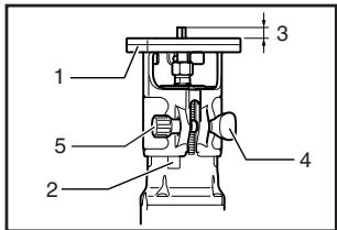
Adjusting bit protrusion
006613
- Base
- Scale
- Bit protrusion
- Clamping nut
- Adjusting screw
To adjust the bit protrusion, loosen the clamping nut and move the tool base up or down as desired by turning the adjusting screw. After adjusting, tighten the clamping nut firmly to secure the tool base.
Switch action
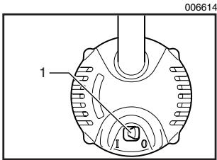
- Switch lever
CAUTION:
- Before plugging in the tool, always be sure that the tool is switched off.
To start the tool, move the switch lever to the I (ON) position. To stop the tool, move the switch lever to the O (OFF) position.
ASSEMBLY
CAUTION:
Always be sure that the tool is switched off and unplugged before carrying out any work on the tool.
Installing or removing trimmer bit

006615
- Loosen
- Tighten
- Hold
CAUTION:
- Do not tighten the collet nut without inserting a bit, or the collet cone will break.
Use only the wrenches provided with the tool.
Insert the bit all the way into the collet cone and tighten the collet nut securely with the two wrenches. To remove the bit, follow the installation procedure in reverse.
OPERATION
Set the tool base on the workpiece to be cut without the bit making any contact. Then turn the tool on and wait until the bit attains full speed. Move the tool forward over the workpiece surface, keeping the tool base flush and advancing smoothly until the cutting is complete.
When doing edge cutting, the workpiece surface should be on the left side of the bit in the feed direction.
001984
- Workpiece
- Bit revolving direction
- View from the top of the tool
- Feed direction
NOTE:
- Moving the tool forward too fast may cause a poor quality of cut, or damage to the bit or motor. Moving the tool forward too slowly may burn and mar the cut. The proper feed rate will depend on the bit size, the kind of workpiece and depth of cut. Before beginning the cut on the actual workpiece, it is advisable to make a sample cut on a piece of scrap lumber. This will show exactly how the cut will look as well as enable you to check dimensions.
001985
- Feed direction
- Bit revolving direction
- Workpiece
- Straight guide
CAUTION:
- Since excessive cutting may cause overload of the motor or difficulty in controlling the tool, the depth of cut should not be more than 3mm (1/8^ ) at a pass when cutting grooves. When you wish to cut grooves more than 3mm (1/8^ ) deep, make several passes with progressively deeper bit settings.
Templet guide
The templet guide provides a sleeve through which the bit passes, allowing use of the trimmer with templet patterns.
Remove the chip deflector.
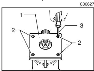
- Base protector
- Screws
- Screwdriver
Loosen the screws and remove the base protector. Place the templet guide on the base and replace the base protector. Then secure the base protector by tightening the screws.
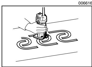
Secure the templet to the workpiece. Place the tool on the templet and move the tool with the templet guide sliding along the side of the templet.
- Bit
- Base
- Templet
- Workpiece
- Templet guide
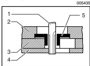
NOTE:
- The workpiece will be cut a slightly different size from the templet. Allow for the distance (X) between
the router bit and the outside of the templet guide. The distance (X) can be calculated by using the following equation:
Distance (X) = (outside diameter of the templet guide - router bit diameter) / 2
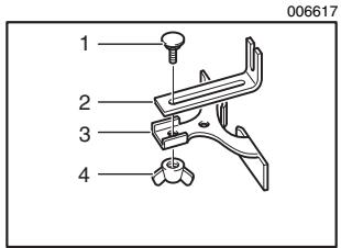
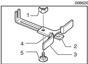
Straight guide (optional accessory)
The straight guide is effectively used for straight cuts when chamfering or grooving.
Attach the guide plate to the straight guide with the bolt and the wing nut.
Remove the chip deflector.
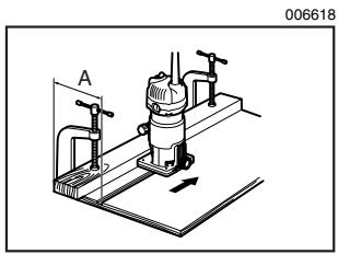
Attach the straight guide with the clamp screw (A). Loosen the wing nut on the straight guide and adjust the distance between the bit and the straight guide. At the desired distance, tighten the wing nut securely.
When cutting, move the tool with the straight guide flush with the side of the workpiece.
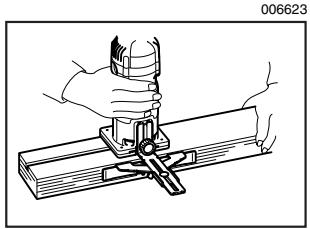
If the distance (A) between the side of the workpiece and the cutting position is too wide for the straight guide, or if the side of the workpiece is not straight, the straight guide cannot be used. In this case, firmly clamp a straight board to the workpiece and use it as a guide against the trimmer base. Feed the tool in the direction of the arrow.
Circular work
- Wing nut
- Guide plate
- Straight guide
- Center hole
- Bolt
Circular work may be accomplished if you assemble the straight guide and guide plate as shown in the figures.
Min. and max. radius of circles to be cut (distance between the center of circle and the center of bit) are as follows:
Min.: 70 ~mm (2 - 3/4^ )
Max.: 221 mm (8 - 11/16")
For cutting circles between 70mm (2 - 3/4") and 121mm (4 - 3/4") in radius.
For cutting circles between 121mm (4 - 3/4") and 221 mm (8 - 11/16") in radius.
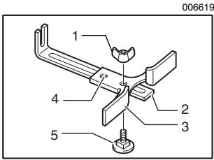
- Wing nut
- Guide plate
- Straight guide
- Center hole
- Bolt
NOTE:
- Circles between 172mm (6 - 3 / 4^ ) and 186mm (7 - 5 / 16^ ) in radius cannot be cut using this guide.
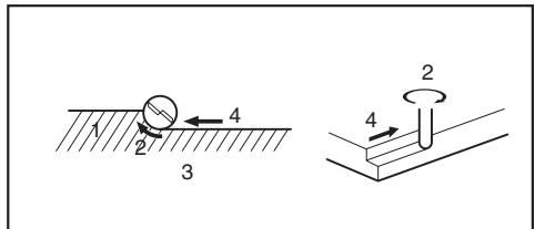
Align the center hole in the straight guide with the center of the circle to be cut. Drive a nail less than 6mm (1 / 4^ ) in diameter into the center hole to secure the straight guide Pivot the tool around the nail in clockwise direction.
1. Nail
2. Center hole
3. Straight guide
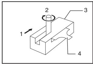
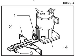
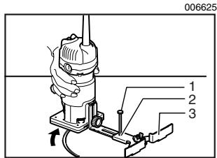
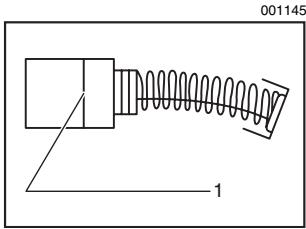
Trimming, curved cuts in veneers for furniture and the like can be done easily with the trimmer guide. The guide roller rides the curve and assures a fine cut.
Install the trimmer guide on the tool base with the clamp screw (A). Loosen the clamp screw (B) and adjust the distance between the bit and the trimmer guide by turning the adjusting screw (1 mm (3/64^) per turn). At the desired distance, tighten the clamp screw (B) to secure the trimmer guide in place.
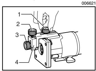
1. Clamp screw (A)
2. Adjusting screw
3. Clamp screw (B)
4. Trimmer guide
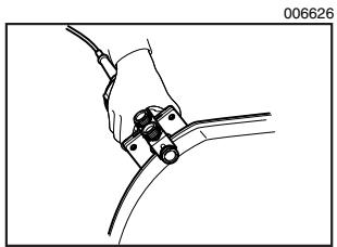
When cutting, move the tool with the guide roller riding the side of the workpiece.

1. Workpiece
2. Bit
3. Guide roller
MAINTENANCE
CAUTION:
Always be sure that the tool is switched off and unplugged before attempting to perform inspection or maintenance.
Replacing carbon brushes
1. Limit mark
Remove and check the carbon brushes regularly. Replace when they wear down to the limit mark. Keep the carbon brushes clean and free to slip in the holders. Both carbon brushes should be replaced at the same time. Use only identical carbon brushes.
Use a screwdriver to remove the brush holder caps. Take out the worn carbon brushes, insert the new ones and secure the brush holder caps.
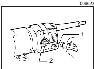
1. Screwdriver
2. Brush holder cap
To maintain product SAFETY and RELIABILITY, repairs, any other maintenance or adjustment should be performed by Makita Authorized or Factory Service Centers, always using Makita replacement parts.
ACCESSORIES
CAUTION:
These accessories or attachments are recommended for use with your Makita tool specified in this manual. The use of any other accessories or attachments might present a risk of injury to persons. Only use accessory or attachment for its stated purpose.
If you need any assistance for more details regarding these accessories, ask your local Makita service center.
Straight & groove forming bits
- Edge forming bits
- Laminate trimming bits
Straight guide assembly
- Trimmer guide assembly
- Trimmer base assembly (For chamfering with straight bit)
- Trimmer shoe
Templet guide
Collet cone 1/4"
Wrench 10
Wrench 17
EN0006-1
MAKITA LIMITED ONE YEAR WARRANTY
Warranty Policy
Every Makita tool is thoroughly inspected and tested before leaving the factory. It is warranted to be free of defects from workmanship and materials for the period of ONE YEAR from the date of original purchase. Should any trouble develop during this one year period, return the COMPLETE tool, freight prepaid, to one of Makita's Factory or Authorized Service Centers. If inspection shows the trouble is caused by defective workmanship or material, Makita will repair (or at our option, replace) without charge.
This Warranty does not apply where:
- repairs have been made or attempted by others:
- repairs are required because of normal wear and tear:
the tool has been abused, misused or improperly maintained:
alterations have been made to the tool.
IN NO EVENT SHALL MAKITA BE LIABLE FOR ANY INDIRECT, INCIDENTAL OR CONSEQUENTIAL DAMAGES FROM THE SALE OR USE OF THE PRODUCT. THIS DISCLAIMER APPLIES BOTH DURING AND AFTER THE TERM OF THIS WARRANTY.
MAKITA DISCLAIMS LIABILITY FOR ANY IMPLIED WARRANTY, INCLUDING IMPLIED WARRANTY OF "MERCHANTABILITY" AND "FITNESS FOR A SPECIFIC PURPOSE," AFTER THE ONE YEAR TERM OF THIS WARRANTY.
This Warranty gives you specific legal rights, and you may also have other rights which vary from state to state. Some states do not allow the exclusion or limitation of incidental or consequential damages, so the above limitation or exclusion may not apply to you. Some states do not allow limitation on how long an implied warranty lasts, so the above limitation may not apply to you.
FRANÇAIS
SPÉCIFICATIONS
Some dust created by power sanding, sawing, grinding, drilling, and other construction activities contains chemicals known to the State of California to cause cancer, birth defects or other reproductive harm. Some examples of these chemicals are:
- lead from lead-based paints,
crystalline silica from bricks and cement and other masonry products, and - arsenic and chromium from chemically-treated lumber.
Your risk from these exposures varies, depending on how often you do this type of work. To reduce your exposure to these chemicals: work in a well ventilated area, and work with approved safety equipment, such as those dust masks that are specially designed to filter out microscopic particles.
< USA solamente >
ADVERTENCIA
Huangpu Jiang Road, Kunshan Economic & Technical Development Zone, Jiangsu P.R. China