RP2301FC - Router MAKITA - Free user manual and instructions
Find the device manual for free RP2301FC MAKITA in PDF.
| Product Type | Router |
| Brand | Makita |
| Model | RP2301FC |
| Collet Chuck Capacity | 12 mm or 1/2" |
| Plunge Capacity | 0 - 70 mm (0 - 2-3/4") |
| No Load Speed Range | 9,000 - 22,000 RPM |
| Variable Speed | Yes, via speed adjusting dial (6 settings) |
| Overall Length | 312 mm (12-1/4") |
| Net Weight | 6.1 kg (13.4 lbs) |
| Electric Brake | Yes |
| Constant Speed Control | Yes, maintains speed under load |
| Soft Start | Yes |
| Speed Adjusting Dial | Settings 1 to 6 (9,000 - 22,000 RPM) |
| Depth Adjustment | Adjustable with stopper pole and fine adjustment knob |
| Stopper Block | Three adjusting hex bolts for different depths |
| Lamp | LED, turns on with trigger, auto-off 10-15 sec after release |
| Double Insulation | Yes (Class II) |
| Dust Collection | Dust nozzle included for vacuum connection |
| Accessories Included | Wrench 24, straight guide, guide holder, dust nozzle |
| Compatible Accessories | Trimmer guide, templet guides, collet sleeves |
Frequently Asked Questions - RP2301FC MAKITA
User questions about RP2301FC MAKITA
0 question about this device. Answer the ones you know or ask your own.
Ask a new question about this device
Download the instructions for your Router in PDF format for free! Find your manual RP2301FC - MAKITA and take your electronic device back in hand. On this page are published all the documents necessary for the use of your device. RP2301FC by MAKITA.
USER MANUAL RP2301FC MAKITA
INSTRUCTION MANUAL MANUEL D'INSTRUCTION MANUAL DE INSTRUCCIONES
Router Défoncéuse Rebajadora
RP1800
RP1801F
RP2301FC
009852

DOUBLE INSULATION DOUBLE ISOLATION DOBLE AISLAMENTO
△WARNING:
For your personal safety, READ and UNDERSTAND before using. SAVE THESE INSTRUCTIONS FOR FUTURE REFERENCE.
△AVERTISSEMENT:
| Model | RP1800 | RP1801F | RP2301FC |
| Collet chuck capacity | 12 mm or 1/2" | ||
| Plunge capacity | 0 - 70 mm (0 - 2-3/4") | ||
| No load speed (RPM) | 22,000/min | 9,000 - 22,000/min | |
| Overall length | 312 mm (12-1/4") | ||
| Net weight | 6.0 kg (13.2 lbs) | 6.1 kg (13.4 lbs) | |
- Due to our continuing programme of research and development, the specifications herein are subject to change without notice.
- Note: Specifications may differ from country to country.
Weight according to EPTA-Procedure 01/2003
GEA004-2
GENERAL SAFETY RULES
WARNING! Read all instructions. Failure to follow all instructions listed below may result in electric shock, fire and/or serious injury. The term "power tool" in all of the warnings listed below refers to your mains-operated (corded) power tool or battery-operated (cordless) power tool.
SAVE THESE INSTRUCTIONS.
The term "power tool" in the warnings refers to your mains-operated (corded) power tool or battery-operated (cordless) power tool.
Work area safety
- Keep work area clean and well lit. Cluttered and dark areas invite accidents.
- Do not operate power tools in explosive atmospheres, such as in the presence of flammable liquids, gases or dust. Power tools create sparks which may ignite the dust or fumes.
- Keep children and bystanders away while operating a power tool. Distractions can cause you to lose control.
Electrical Safety
- Power tool plugs must match the outlet. Never modify the plug in any way. Do not use any adapter plugs with earthed (grounded) power tools. Unmodified plugs and matching outlets will reduce risk of electric shock.
- Avoid body contact with earthed or grounded surfaces such as pipes, radiators, ranges and refrigerators. There is an increased risk of electric shock if your body is earthed or grounded.
- Do not expose power tools to rain or wet conditions. Water entering a power tool will increase the risk of electric shock.
- Do not abuse the cord. Never use the cord for carrying, pulling or unplugging the power tool. Keep cord away from heat, oil, sharp edges or moving parts. Damaged or entangled cords
increase the risk of electric shock.
- When operating a power tool outdoors, use an extension cord suitable for outdoor use. Use of a cord suitable for outdoor use reduces the risk of electric shock.
Personal Safety
- Stay alert, watch what you are doing and use common sense when operating a power tool. Do not use a power tool while you are tired or under the influence of drugs, alcohol or medication. A moment of inattention while operating power tools may result in serious personal injury.
- Use safety equipment. Always wear eye protection. Safety equipment such as dust mask, non-skid safety shoes, hard hat, or hearing protection used for appropriate conditions will reduce personal injuries.
- Avoid accidental starting. Ensure the switch is in the off-position before plugging in. Carrying power tools with your finger on the switch or plugging in power tools that have the switch on invites accidents.
- Remove any adjusting key or wrench before turning the power tool on. A wrench or a key left attached to a rotating part of the power tool may result in personal injury.
- Do not overreach. Keep proper footing and balance at all times. This enables better control of the power tool in unexpected situations.
- Dress properly. Do not wear loose clothing or jewellery. Keep your hair, clothing, and gloves away from moving parts. Loose clothes, jewellery or long hair can be caught in moving parts.
- If devices are provided for the connection of dust extraction and collection facilities, ensure these are connected and properly used. Use of these devices can reduce dust-related hazards.
Power tool use and care
- Do not force the power tool. Use the correct power tool for your application. The correct power tool will do the job better and safer at the rate for which it was designed.
- Do not use the power tool if the switch does not turn it on and off. Any power tool that cannot be controlled with the switch is dangerous and must be repaired.
- Disconnect the plug from the power source and/or the battery pack from the power tool before making any adjustments, changing accessories, or storing power tools. Such preventive safety measures reduce the risk of starting the power tool accidentally.
- Store idle power tools out of the reach of children and do not allow persons unfamiliar with the power tool or these instructions to operate the power tool. Power tools are dangerous in the hands of untrained users.
- Maintain power tools. Check for misalignment or binding of moving parts, breakage of parts and any other condition that may affect the power tools operation. If damaged, have the power tool repaired before use. Many accidents are caused by poorly maintained power tools.
- Keep cutting tools sharp and clean. Properly maintained cutting tools with sharp cutting edges
are less likely to bind and are easier to control.
- Use the power tool, accessories and tool bits etc. in accordance with these instructions and in the manner intended for the particular type of power tool, taking into account the working conditions and the work to be performed. Use of the power tool for operations different from those intended could result in a hazardous situation.
SERVICE
- Have your power tool serviced by a qualified repair person using only identical replacement parts. This will ensure that the safety of the power tool is maintained.
- Follow instruction for lubricating and changing accessories.
- Keep handles dry, clean and free from oil and grease.
USE PROPER EXTENSION CORD. Make sure your extension cord is in good condition. When using an extension cord, be sure to use one heavy enough to carry the current your product will draw. An undersized cord will cause a drop in line voltage resulting in loss of power and overheating. Table 1 shows the correct size to use depending on cord length and nameplate ampere rating. If in doubt, use the next heavier gage. The smaller the gage number, the heavier the cord.
Table 1: Minimum gage for cord
| Ampere Rating | Volts | Total length of cord in feet | ||||
| 120 V | 25 ft. | 50 ft. | 100 ft. | 150 ft. | ||
| More Than | Not More Than | AWG | ||||
| 0 | 6 | 18 | 16 | 16 | 14 | |
| 6 | 10 | 18 | 16 | 14 | 12 | |
| 10 | 12 | 16 | 16 | 14 | 12 | |
| 12 | 16 | 14 | 12 | Not Recommended | ||
000173
SPECIFIC SAFETY RULES
DO NOT let comfort or familiarity with product (gained from repeated use) replace strict adherence to router safety rules. If you use this tool unsafely or incorrectly, you can suffer serious personal injury.
- Hold power tools by insulated gripping surfaces when performing an operation where the cutting tool may contact hidden wiring or its own cord. Contact with a "live" wire will make exposed metal parts of the tool "live" and shock the operator.
GEB018-1
- Use clamps or another practical way to secure and support the workpiece to a stable platform. Holding the work by hand or against your body leaves it unstable and may lead to loss of control.
- Wear hearing protection during extended period of operation.
- Handle the bits very carefully.
- Check the bit carefully for cracks or damage before operation. Replace cracked or damaged bit immediately.
- Avoid cutting nails. Inspect for and remove all nails from the workpiece before operation.
- Hold the tool firmly with both hands.
-
Keep hands away from rotating parts.
-
Make sure the bit is not contacting the workpiece before the switch is turned on.
- Before using the tool on an actual workpiece, let it run for a while. Watch for vibration or wobbling that could indicate improperly installed bit.
- Be careful of the bit rotating direction and the feed direction.
- Do not leave the tool running. Operate the tool only when hand-held.
- Always switch off and wait for the bit to come to a complete stop before removing the tool from workpiece.
- Do not touch the bit immediately after operation; it may be extremely hot and could burn your skin.
- Do not smear the tool base carelessly with thinner, gasoline, oil or the like. They may cause cracks in the tool base.
- Draw attention to the need to use cutters of the correct shank diameter and which are suitable for the speed of the tool.
- Some material contains chemicals which may be toxic. Take caution to prevent dust inhalation and skin contact. Follow material supplier safety data.
- Always use the correct dust mask/respirator for the material and application you are working with.
SAVE THESE INSTRUCTIONS.
WARNING:
MISUSE or failure to follow the safety rules stated in this instruction manual may cause serious personal injury.
USD201-2
Symbols
The followings show the symbols used for tool.
v volts
A amperes
Hz hertz
alternating current
no load speed
Class II Construction
.../min . revolutions or reciprocation per minute r/min
FUNCTIONAL DESCRIPTION
CAUTION:
Always be sure that the tool is switched off and unplugged before adjusting or checking function on the tool.
Adjusting the depth of cut
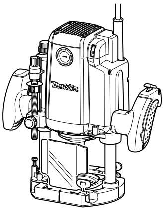
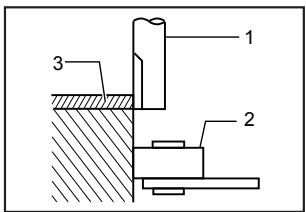
009857
- Adjusting knob
- Lock lever
- Stopper pole setting nut
- Fast-feed button
- Adjusting bolt
- Stopper block
- Depth pointer
- Stopper pole
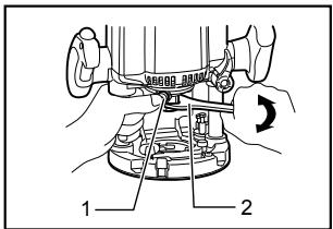
Place the tool on a flat surface. Loosen the lock lever and lower the tool body until the bit just touches the flat surface. Tighten the lock lever to lock the tool body.
Turn the stopper pole setting nut counterclockwise. Lower the stopper pole until it makes contact with the adjusting bolt. Align the depth pointer with the "0" graduation. The depth of cut is indicated on the scale by the depth pointer.
While pressing the fast-feed button, raise the stopper pole until the desired depth of cut is obtained. Minute depth adjustments can be obtained by turning the adjusting knob (1 mm (3/64") per turn).
By turning the stopper pole setting nut clockwise, you can fasten the stopper pole firmly.
Now, your predetermined depth of cut can be obtained by loosening the lock lever and then lowering the tool body until the stopper pole makes contact with the adjusting hex bolt of the stopper block.
Nylon nut

1. Nylon nut
009855
The upper limit of the tool body can be adjusted by turning the nylon nut.
CAUTION:
Do not lower the nylon nut too low. The bit will protrude dangerously.
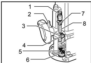
Stopper block
009858
- Stopper pole
- Adjusting bolt
- Stopper block
The stopper block has three adjusting hex bolts which raise or lower 0.8mm (1/32") per turn. You can easily obtain three different depths of cut using these adjusting hex bolts without readjusting the stopper pole.
Adjust the lowest hex bolt to obtain the deepest depth of cut, following the method of "Adjusting depth of cut". Adjust the two remaining hex bolts to obtain shallower depths of cut. The differences in height of these hex bolts are equal to the differences in depths of cut.
To adjust the hex bolts, turn the hex bolts with a screwdriver or wrench. The stopper block is also convenient for making three passes with progressively deeper bit settings when cutting deep grooves.
CAUTION:
- Since excessive cutting may cause overload of the motor or difficulty in controlling the tool, the depth of cut should not be more than 15mm (19/32") at a pass when cutting grooves with an 8 mm (5/16") diameter bit.
- When cutting grooves with a 20 ~mm (13/16") diameter bit, the depth of cut should not be more than 5 ~mm (3/16") at a pass.
- For extra-deep grooving operations, make two or three passes with progressively deeper bit settings.
Switch action
009864
- Lock button
- Switch trigger
CAUTION:
- Before plugging in the tool, always check to see that the switch trigger actuates properly and returns to the "OFF" position when released.
Make sure that the shaft lock is released before the switch is turned on.
To prevent the switch trigger from being accidentally pulled, a lock button is provided.
To start the tool, depress the lock button and pull the switch trigger. Release the switch trigger to stop.
For continuous operation, pull the switch trigger and then depress the lock button further. To stop the tool, pull the switch trigger so that the lock button returns automatically. Then release the switch trigger.
After releasing the switch trigger, the lock-off function works to prevent the switch trigger from being pulled.
CAUTION:
- Hold the tool firmly when turning off the tool, to overcome the reaction.
Electric brake
For model RP1801F, RP2301FC only
This tool is equipped with an electric brake. If the tool consistently fails to quickly stop after switch trigger moving to the "OFF" position, have tool serviced at a Makita service center.
Electronic function
For model RP2301FC only
Constant speed control
Possible to get fine finish, because the rotating speed is kept constantly even under the loaded condition.
- Additionally, when the load on the tool exceeds admissible levels, power to the motor is reduced to protect the motor from overheating. When the load returns to admissible levels, the tool will operate as normal.
Soft start feature
Soft start because of suppressed starting shock.
Speed adjusting dial
For model RP2301FC only
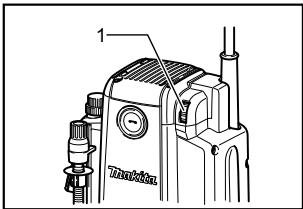
1. Speed adjusting dial
009865
The tool speed can be changed by turning the speed adjusting dial to a given number setting from 1 to 6.
Higher speed is obtained when the dial is turned in the direction of number 6. And lower speed is obtained when it is turned in the direction of number 1.
This allows the ideal speed to be selected for optimum material processing, i.e. the speed can be correctly adjusted to suit the material and bit diameter.
Refer to the table for the relationship between the number settings on the dial and the approximate tool speed.
| Number | RPM |
| 1 | 9,000 |
| 2 | 11,000 |
| 3 | 14,000 |
| 4 | 17,000 |
| 5 | 20,000 |
| 6 | 22,000 |
009876
CAUTION:
If the tool is operated continuously at low speeds for a long time, the motor will get overloaded, resulting in tool malfunction.
The speed adjusting dial can be turned only as far as 6 and back to 1. Do not force it past 6 or 1, or the speed adjusting function may no longer work.
Lighting up the lamps
For model RP1801F, RP2301FC only
- Lamp
009866
CAUTION:
- Do not look in the light or see the source of light directly.
Pull the switch trigger to turn on the light. The lamp keeps on lighting while the switch trigger is being pulled.
The lamp turns off 10 - 15 seconds after releasing the trigger.
NOTE:
Use a dry cloth to wipe the dirt off the lens of lamp. Be careful not to scratch the lens of lamp, or it may lower the illumination.
ASSEMBLY
CAUTION:
Always be sure that the tool is switched off and unplugged before carrying out any work on the
tool.
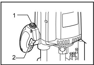
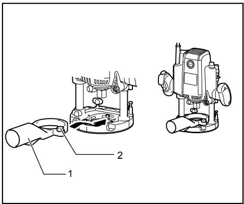
Installing or removing the bit
1. Shaft lock
2. Wrench
009854
CAUTION:
Install the bit securely. Always use only the wrench provided with the tool. A loose or overtightened bit can be dangerous.
Use always a collet which is suitable for the shank diameter of the bit.
- Do not tighten the collet nut without inserting a bit or install small shank bits without using a collet sleeve. Either can lead to breakage of the collet cone.
Use only router bits of which the maximum speed, as indicated on the bit, does exceed the maximum speed of the router.
Insert the bit all the way into the collet cone. Press the shaft lock to keep the shaft stationary and use the wrench to tighten the collet nut securely. When using router bits with smaller shank diameter, first insert the appropriate collet sleeve into the collet cone, then install the bit as described above.
To remove the bit, follow the installation procedure in reverse.
OPERATION
CAUTION:
Before operation, always make sure that the tool body automatically rises to the upper limit and the bit does not protrude from the tool base when the lock lever is loosened.
Before operation, always make sure that the chip deflector is installed properly.
009860
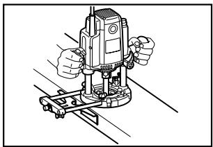
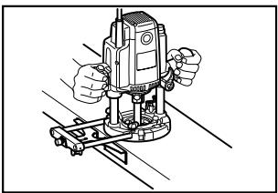
Always use both grips and firmly hold the tool by both grips during operations.
Set the tool base on the workpiece to be cut without the bit making any contact. Then turn the tool on and wait until the bit attains full speed. Lower the tool body and move the tool forward over the workpiece surface, keeping the tool base flush and advancing smoothly until the cutting is complete.
When doing edge cutting, the workpiece surface should be on the left side of the bit in the feed direction.
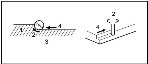
1.Workpiece
2. Bit revolving direction
3. View from the top of the tool
4. Feed direction
001984
NOTE:
- Moving the tool forward too fast may cause a poor quality of cut, or damage to the bit or motor. Moving the tool forward too slowly may burn and mar the cut. The proper feed rate will depend on the bit size, the kind of workpiece and depth of cut. Before beginning the cut on the actual workpiece, it is advisable to make a sample cut on a piece of scrap lumber. This will show exactly how the cut will look as well as enable you to check dimensions.
- When using the straight guide or the trimmer guide, be sure to install it on the right side in the feed direction. This will help to keep it flush with the side of the workpiece.
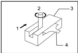
- Feed direction
- Bit revolving direction
- Workpiece
- Straight guide
001985
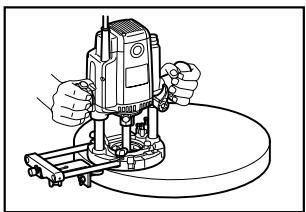
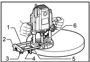
Straight guide
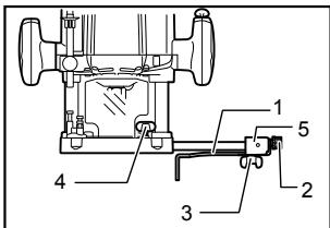
009859
- Straight guide
- Fine adjusting screw
- Clamping screw (B)
- Clamping screw (A)
- Guide holder
The straight guide is effectively used for straight cuts when chamfering or grooving.
Install the straight guide on the guide holder with the clamping screw (B). Insert the guide holder into the holes in the tool base and tighten the clamping screw (A) To adjust the distance between the bit and the straight guide, loosen the clamping screw (B) and turn the fine adjusting screw (1.5 mm or about 1/16" per turn). At the desired distance, tighten the clamping screw (B) to secure the straight guide in place.
009860
Wider straight guide of desired dimensions may be made by using the convenient holes in the guide to bolt on extra pieces of wood.
003684
- More than 15mm (5/8")
- Straight guide
- Wood
When using a large diameter bit, attach pieces of wood to the straight guide which have a thickness of more than 15mm (5 / 8^ ) to prevent the bit from striking the straight guide.
When cutting, move the tool with the straight guide flush with the side of the workpiece.
If the distance between the side of the workpiece and the cutting position is too wide for the straight guide, or if the side of the workpiece is not straight, the straight
guide cannot be used. In this case, firmly clamp a straight board to the workpiece and use it as a guide against the trimmer base. Feed the tool in the direction of the arrow.
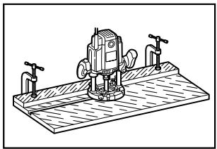
009861
Templet guide (optional accessory)
009862
The templet guide provides a sleeve through which the bit passes, allowing use of the tool with templet patterns. To install the templet guide, pull the lock plate lever and insert the templet guide.
009863
Secure the templet to the workpiece. Place the tool on the templet and move the tool with the templet guide sliding along the side of the templet.
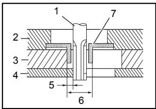
003695
- Template guide
-
Lock plate
-
Bit
- Base
- Templet
- Workpiece
- Distance (X)
- Outside diameter of the templet guide
- Templet guide
NOTE:
The workpiece will be cut a slightly different size from the templet. Allow for the distance (X) between the bit and the outside of the templet guide. The distance (X) can be calculated by using the following equation:
Distance (X) = (outside diameter of the templet guide - bit diameter) / 2
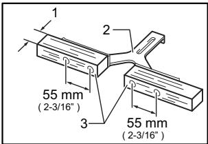
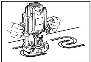
Trimmer guide (optional accessory)
009867
Trimming, curved cuts in veneers for furniture and the like can be done easily with the trimmer guide. The guide roller rides the curve and assures a fine cut.
Install the trimmer guide on the guide holder with the clamping screw (B). Insert the guide holder into the holes in the tool base and tighten the clamping screw (A). To adjust the distance between the bit and the trimmer guide, loosen the clamping screw (B) and turn the fine adjusting screw (1.5 mm or 1/16" per turn). When adjusting the guide roller up or down, loosen the clamping screw (C). After adjusting, tighten all the clamping screws securely.
009868
- Guide holder
- Adjusting screw
- Clamping screw (B)
- Clamping screw (C)
- Trimmer guide
- Clamping screw (A)
When cutting, move the tool with the guide roller riding the side of the workpiece.
003701
- Bit
- Guide roller
- Workpiece
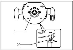
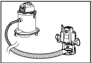
Dust nozzle set (Accessory)
1. Dust nozzle
2. Clamping screw
Use the dust nozzle for dust extraction. Install the dust nozzle on the tool base using the thumb screw so that protrusion on the dust nozzle fit to the notch in the tool base.
Then connect a vacuum cleaner to the dust nozzle.
009877
MAINTENANCE
CAUTION:
Always be sure that the tool is switched off and unplugged before attempting to perform inspection or maintenance.
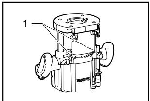
Replacing carbon brushes
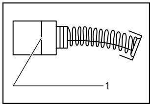
1. Limit mark
001145
Remove and check the carbon brushes regularly. Replace when they wear down to the limit mark. Keep the carbon brushes clean and free to slip in the holders. Both carbon brushes should be replaced at the same time. Use only identical carbon brushes.
Use a screwdriver to remove the brush holder caps. Take out the worn carbon brushes, insert the new ones and secure the brush holder caps.
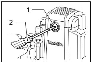
1. Brush holder cap
2. Screwdriver
009869
For model RP1801F, RP2301FC only
After replacing brushes, plug in the tool and break in brushes by running tool with no load for about 10 minutes. Then check the tool while running and electric brake operation when releasing the switch trigger. If electric brake is not working well, ask your local Makita service center for repair.
To maintain product SAFETY and RELIABILITY, repairs, any other maintenance or adjustment should be performed by Makita Authorized or Factory Service Centers, always using Makita replacement parts.
ACCESSORIES
CAUTION:
These accessories or attachments are recommended for use with your Makita tool specified in this manual. The use of any other accessories or attachments might present a risk of injury to persons. Only use accessory or attachment for its stated purpose.
If you need any assistance for more details regarding these accessories, ask your local Makita Service Center.
Straight & groove forming bits
- Edge forming bits
Laminate trimming bits
Straight guide
- Trimmer guide
Guide holder
Templet guides
Templet guide adapter
Lock nut
Collet sleeve 3/8", 1/4"
Wrench 24
MAKITA LIMITED ONE YEAR WARRANTY
Warranty Policy
Every Makita tool is thoroughly inspected and tested before leaving the factory. It is warranted to be free of defects from workmanship and materials for the period of ONE YEAR from the date of original purchase. Should any trouble develop during this one year period, return the COMPLETE tool, freight prepaid, to one of Makita's Factory or Authorized Service Centers. If inspection shows the trouble is caused by defective workmanship or material, Makita will repair (or at our option, replace) without charge.
This Warranty does not apply where:
- repairs have been made or attempted by others:
- repairs are required because of normal wear and tear:
the tool has been abused, misused or improperly maintained:
alterations have been made to the tool.
IN NO EVENT SHALL MAKITA BE LIABLE FOR ANY INDIRECT, INCIDENTAL OR CONSEQUENTIAL DAMAGES FROM THE SALE OR USE OF THE PRODUCT. THIS DISCLAIMER APPLIES BOTH DURING AND AFTER THE TERM OF THIS WARRANTY.
MAKITA DISCLAIMS LIABILITY FOR ANY IMPLIED WARRANTYES, INCLUDING IMPLIED WARRANTYES OF "MERCHANTABILITY" AND "FITNESS FOR A SPECIFIC PURPOSE," AFTER THE ONE YEAR TERM OF THIS WARRANTY.
This Warranty gives you specific legal rights, and you may also have other rights which vary from state to state. Some states do not allow the exclusion or limitation of incidental or consequential damages, so the above limitation or exclusion may not apply to you. Some states do not allow limitation on how long an implied warranty lasts, so the above limitation may not apply to you.
FRANÇAIS
SPÉCIFICATIONS
construction, catalogue II
Some dust created by power sanding, sawing, grinding, drilling, and other construction activities contains chemicals known to the State of California to cause cancer, birth defects or other reproductive harm. Some examples of these chemicals are:
- lead from lead-based paints,
crystalline silica from bricks and cement and other masonry products, and - arsenic and chromium from chemically-treated lumber.
Your risk from these exposures varies, depending on how often you do this type of work. To reduce your exposure to these chemicals: work in a well ventilated area, and work with approved safety equipment, such as those dust masks that are specially designed to filter out microscopic particles.
< USA solamente >