2414NB - Miter saw MAKITA - Free user manual and instructions
Find the device manual for free 2414NB MAKITA in PDF.
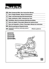
User questions about 2414NB MAKITA
0 question about this device. Answer the ones you know or ask your own.
Ask a new question about this device
Download the instructions for your Miter saw in PDF format for free! Find your manual 2414NB - MAKITA and take your electronic device back in hand. On this page are published all the documents necessary for the use of your device. 2414NB by MAKITA.
USER MANUAL 2414NB MAKITA
natural_image
Line drawing of a mechanical device with a circular component mounted on a base (no text or symbols)
text_image
1 2 3 41
text_image
5 6 8 7 10 9 42
text_image
Technical diagram showing mechanical assembly with labeled parts 11 and 12, likely illustrating a turning or mounting process.3
text_image
(B) 13 (A)4
text_image
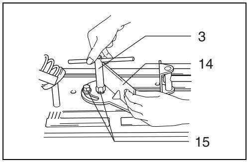
3 14 155
text_image
15 14 35 mm6
text_image
3 14 157
text_image
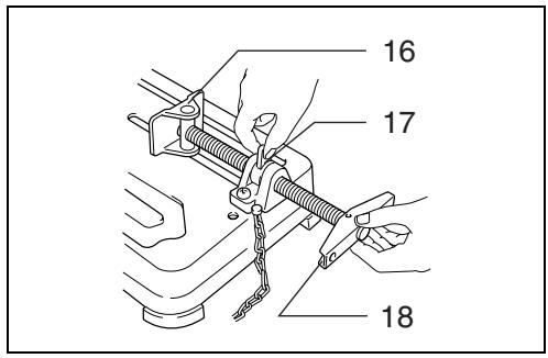
16 17 188
natural_image
Line drawing of a manual clamping device with hands operating it (no text or symbols)9
text_image
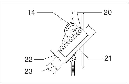
14 20 22 23 2110
text_image
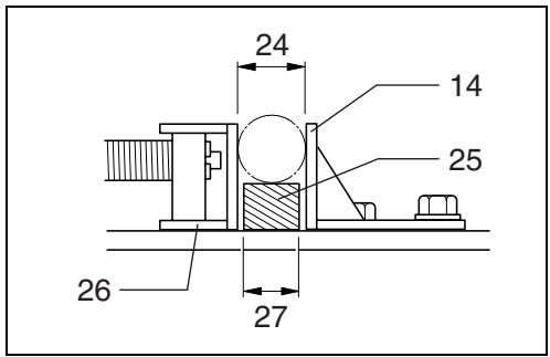
24 14 25 26 2711

text_image
2812
text_image
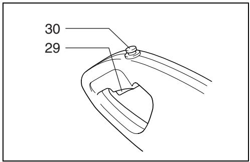
30 2913
text_image
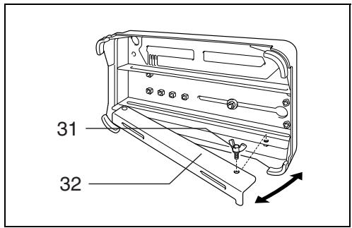
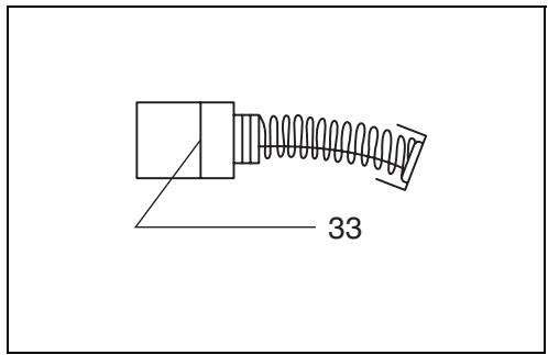
31 3214
natural_image
Line drawing of a mechanical device with no visible text or symbols15
text_image
3316

text_image
34 3517
Symbols
The followings show the symbols used for the tool. Be sure that you understand their meaning before use.
Symboles
Explanation of general view
| 1 | Safety guide | 13 | Stopper plate | 24 | Diameter of workpiece |
| 2 | Shaft lock | 14 | Guide plate | 25 | Spacer block |
| 3 | Socket wrench | 15 | Hex bolts | 26 | Vise |
| 4 | Cut-off wheel | 16 | Vise plate | 27 | Width of spacer block |
| 5 | Inner flange | 17 | Vise nut | 28 | Blocks |
| 6 | O-ring | 18 | Vise handle | 29 | Switch trigger |
| 7 | Spindle | 19 | Spacer block | 30 | Lock button/Lock-off button |
| 8 | Ring | 20 | Straight piece of wood(Spacer) vm | 31 | Wing bolt |
| 9 | Outer flange | 32 | Under cover | ||
| 10 | Hex bolt | 21 | Over 190 mm long | 33 | Limit mark |
| 11 | Screw | 22 | Over 45 mm wide | 34 | Screwdriver |
| 12 | Spark guard | 23 | Over 65 mm wide | 35 | Brush holder cap |
SPECIFICATIONS
| Model | 2414NB |
| Wheel diameter | 355 mm |
| Hole diameter | 25.4 mm |
| No load speed (min ^-1 ) | 3,800 |
| Dimensions (L x W x H) | |
| With under cover | 500 mm x 280 mm x 620 mm |
| Without under cover | 500 mm x 280 mm x 600 mm |
| Net weight | |
| For tools with European type safety guide and under cover | 18.5 kg |
| For tools with European type safety guide and without under cover | 17.8 kg |
- Due to our continuing program of research and development, the specifications herein are subject to change without notice.
- Note: Specifications may differ from country to country.
Intended use
The tool is intended for cutting in masonry and ferrous materials with appropriate abrasive cut-off wheel.
Power supply
The tool should be connected only to a power supply of the same voltage as indicated on the nameplate, and can only be operated on single-phase AC supply. They are double-insulated in accordance with European Standard and can, therefore, also be used from sockets without earth wire.
Safety hints
For your own safety, please refer to the enclosed safety instructions.
ADDITIONAL SAFETY RULES
ENB066-1
- Wear protective glasses. Also wear hearing protection during extended periods of operation.
- Use only wheels recommended by the manufacturer which have a maximum operating speed at least as high as "No Load RPM" marked on the tool's nameplate. Use only fiberglass-reinforced cut-off wheels.
- Check the wheel carefully for cracks or damage before operation. Replace cracked or damaged wheel immediately.
- Secure the wheel carefully.
- Use only flanges specified for this tool.
-
Be careful not to damage the spindle, flanges (especially the installing surface) or bolt, or the wheel itself might break.
-
Keep guards in place and in working order.
- Hold the handle firmly.
- Keep hands away from rotating parts.
- Make sure the wheel is not contacting the workpiece before the switch is turned on.
- Before using the tool on an actual workpiece, let it simply run for several minutes first. Watch for flutter or excessive vibration that might be caused by poor installation or a poorly balanced wheel.
- Watch out for flying sparks when operating. They can cause injury or ignite combustible materials.
- Remove material or debris from the area that might be ignited by sparks. Be sure that others are not in the path of the sparks. Keep a proper, charged fire extinguisher closely available.
- Use the cutting edge of the wheel only. Never use side surface.
- If the wheel stops during the operation, makes an odd noise or begins to vibrate, switch off the tool immediately.
- Always switch off and wait for the wheel to come to a complete stop before removing, securing workpiece, working vise, changing work position, angle or the wheel itself.
- Do not touch the workpiece immediately after operation; it is extremely hot and could burn your skin.
- Store wheels in a dry location only.
SAVE THESE INSTRUCTIONS.
OPERATING INSTRUCTIONS
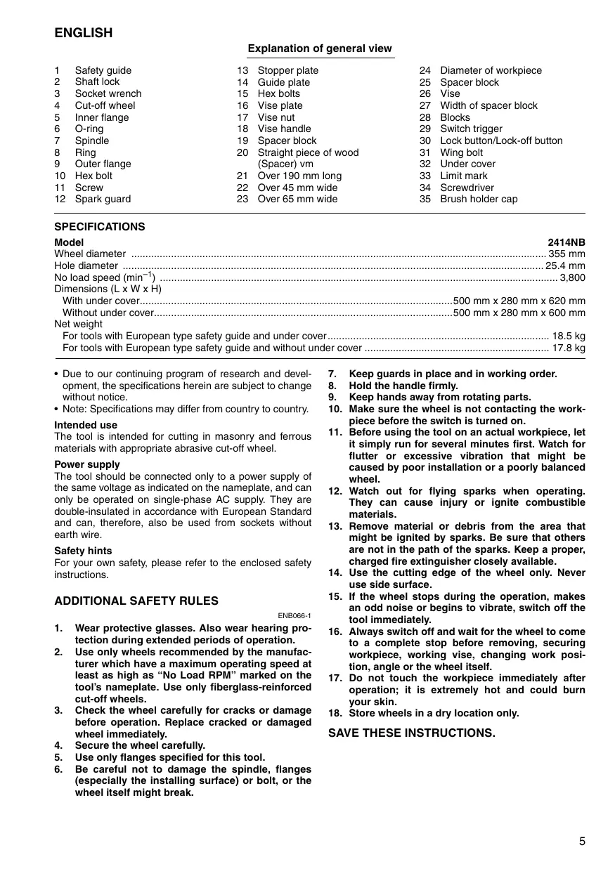
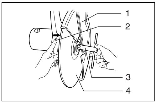
Removing or installing cut-off wheel (Fig. 1 & 2)
Important:
Always be sure that the tool is switched off and unplugged before removing or installing the wheel.
To remove the wheel, raise the safety guide. Press the shaft lock so that the wheel cannot revolve and use the socket wrench to loosen the hex bolt by turning it counterclockwise.
Then remove the hex bolt, outer flange and wheel.
Note: Do not remove the inner flange, ring and O-ring.
To install the wheel, follow the removal procedures in reverse.
CAUTION:
- Be sure to tighten the hex bolt securely. Insufficient tightening of the hex bolt may result in severe injury. Use the socket wrench provided to help assure proper tightening.
- Always use only the proper inner and outer flanges which are provided with this tool.
• Always lower the safety guide after replacing the wheel.
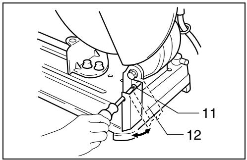
Spark guard (Fig. 3)
The spark guard is factory-installed with its lower edge contacting the base. Operating the tool in this position will cause many sparks to fly around. Loosen the screw and adjust the spark guard to a position at which minimum sparks will fly around.
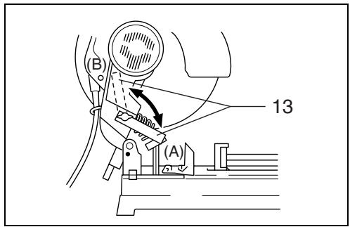
Stopper plate (Fig. 4)
The stopper plate prevents the cut-off wheel from contacting the workbench or floor. When a new wheel is installed, set the stopper plate to position (A). When the wheel wears down to the extent that the lower portion of the workpiece is left uncut, set the stopper plate to position (B) to allow increased cutting capacity with a worn-down wheel.
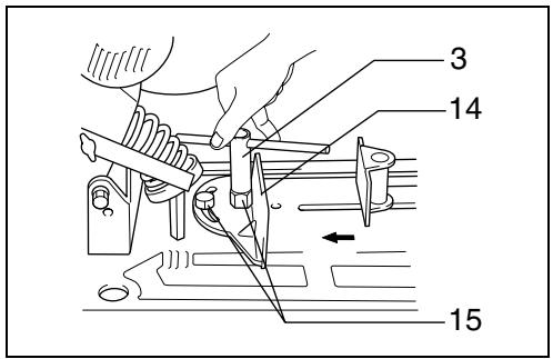
Interval between vise and guide plate (Fig. 5 & 6)
The original spacing or interval between the vise and the guide plate is 0 – 170 mm. If your work requires wider spacing or interval, proceed as follows to change the spacing or interval.
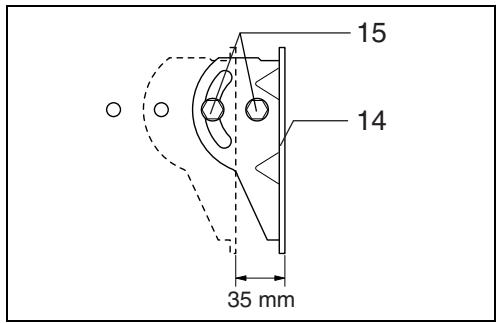
Remove the two hex bolts which secure the guide plate. Move the guide plate as shown in Fig.6 and secure it using the hex bolts. The following interval settings are possible:
35 – 205 mm
70 - 240 mm
CAUTION:
Remember that narrow workpieces may not be secured safely when using the two, wider interval settings.
Setting for desired cutting angle (Fig. 7)
To change the cutting angle, loosen the two hex bolts which secure the guide plate. Move the guide plate to the desired angle (0^-45^) and tighten the hex bolts securely.
CAUTION:
Never perform right miter cuts when the guide plate is set at the 35 – 205 mm or 70 – 240 mm position.
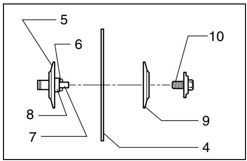
Securing workpieces
By turning the vise handle counterclockwise and then flipping the vise nut to the left, the vise is released from the shaft threads and can be moved rapidly in and out. To grip workpieces, push the vise handle until the vise plate contacts the workpiece. Flip the vise nut to the right and then turn the vise handle clockwise to securely retain the workpiece. (Fig. 8)
CAUTION:
Always set the vise nut to the right fully when securing the workpiece. Failure to do so may result in insufficient securing of the workpiece. This could cause the workpiece to be ejected or cause a dangerous breakage of the wheel.
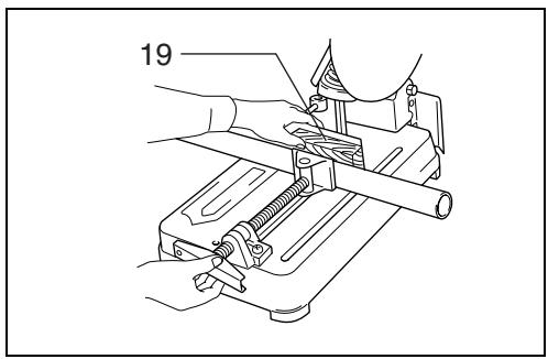
When the cut-off wheel has worn down considerably, use a spacer block of sturdy, non-flammable material behind the workpiece as shown in Fig. 9. You can more efficiently utilize the worn wheel by using the mid point on the periphery of the wheel to cut the workpiece.
When cutting workpieces over 65 mm wide at an angle, attach a straight piece of wood (spacer) over 190 mm long x 45 mm wide to the guide plate as shown in Fig. 10. Attach this spacer with screws through the holes in the guide plate.
If you use a spacer block which is slightly narrower than the workpiece as shown in Fig. 11, you can also utilize the wheel economically.
Long workpieces must be supported by blocks of non-flammable material on either side so that it will be level with the base top. (Fig. 12)
Switch action
CAUTION:
Before plugging in the tool, always check to see that the switch trigger actuates properly and returns to the "OFF" position when released.
For tool with lock button (Fig. 13)
To start the tool, simply pull the trigger. Release the trigger to stop. For continuous operation, pull the trigger and then push in the lock button. To stop the tool from the locked position, pull the trigger fully, then release it.
For tool with lock-off button (Fig. 13)
To prevent the trigger from being accidentally pulled, a lock-off button is provided. To start the tool, press the lock-off button and pull the trigger. Release the trigger to stop.
Operation
Hold the handle firmly. Switch on the tool and wait until the wheel attains full speed before lowering gently into the cut. When the wheel contacts the workpiece, gradually bear down on the handle to perform the cut. When the cut is completed, switch off the tool and WAIT UNTIL THE WHEEL HAS COME TO A COMPLETE STOP before returning the handle to the fully elevated position.
CAUTION:
Proper handle pressure during cutting and maximum cutting efficiency can be determined by the amount of sparks that is produced while cutting. Your pressure on the handle should be adjusted to produce the maximum amount of sparks. Do not force the cut by applying excessive pressure on the handle. Reduced cutting efficiency, premature wheel wear, as well as, possible damage to the tool, cut-off wheel or workpiece may result.
Cutting capacity
Max. cutting capacity varies depending upon the cutting angle and workpiece shape.
Applicable wheel diameter: 355 mm.
| Cutting angle\Workpiece shape | 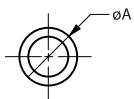 | 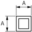 | A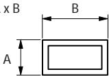 | 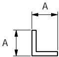 |
| 90° | 115 mm | 119 mm | 115 mm x 130 mm102 mm x 194 mm70 mm x 233 mm | 137 mm |
| 45° | 115 mm | 106 mm | 115 mm x 103 mm | 100 mm |
For tools with the under cover (Fig. 14)
To remove the collected dust from the under cover, place the tool with its side up and pull the under cover open after removing the wing bolt as shown in the figure. Be sure to close and secure the under cover with the wing bolt after the removal of dust.
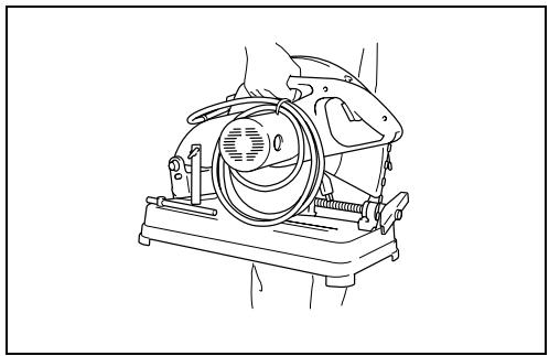
Carrying the tool (Fig. 15)
Fold down the tool head to the position where you can attach the chain to the hook on the handle.
MAINTENANCE
CAUTION:
Always be sure that the tool is switched off and unplugged before carrying out any work on the tool.
Replacement of carbon brushes (Fig. 16 & 17)
Replace carbon brushes when they are worn down to the limit mark. Both identical carbon brushes should be replaced at the same time.
To maintain product safety and reliability, repairs, maintenance or adjustment should be carried out by a Makita Authorized Service Center.
Descriptif
These accessories or attachments are recommended for use with your Makita tool specified in this manual. The use of any other accessories or attachments might present a risk of injury to persons. The accessories or attachments should be used only in the proper and intended manner.
F ACCESSOIRES
ATTENTION :
EC-DECLARATION OF CONFORMITY
We declare under our sole responsibility that this product is in compliance with the following standards or standardized documents,
EN61029, EN55014, EN610000
in accordance with Council Directives, 73/23/EEC, 89/336/EEC and 98/37/EC.
FRANÇAISE
DÉCLARATION DE CONFORMITÉ CE
EU-DEKLARATION OM KONFORMITET
Michigan Drive, Tongwell, Milton Keynes,
Bucks MK15 8JD, ENGLAND
ENGLISH
Noise and Vibration
The typical A-weighted noise levels are
sound pressure level: 97 dB (A)
sound power level: 110 dB (A)
- Wear ear protection.
The typical weighted root mean square acceleration value is not more than 2.5 m/s^2 .