
LS1017L - Miter saw MAKITA - Free user manual and instructions
Find the device manual for free LS1017L MAKITA in PDF.

| Product Type | Compound Miter Saw (miter and bevel cuts) with sliding function |
| Brand / Model | MAKITA LS1017L |
| Blade Diameter | 255 mm (10") |
| Blade Arbor Diameter | 15.88 mm (5/8") |
| No-Load Speed | ~ 3200 rpm (estimated for European model) |
| Power / Supply | 230 V ~ 50 Hz (depending on version) / Motor 1200 W (estimated) |
| Maximum Cutting Capacity (0°/0°) | 91 mm x 305 mm (H x D) |
| Maximum Cutting Capacity (45° left / 45° left bevel) | 50 mm x 200 mm (H x D) |
| Miter Angle Range | 0° - 45° left / 0° - 60° right |
| Bevel Angle Range | Left 0° - 45° / Right 0° - 5° (with positive stop) |
| Laser (LS1017L only) | Class II laser line, wavelength 660 nm, power < 1 mW |
| Dimensions (L x D x H) | 825 mm x 536 mm x 581 mm |
| Weight (according to EPTA procedure) | Approximately 23.5 kg |
| Special Functions | Electric brake, soft start, slide lock, adjustable depth stop |
| Protection System | Spring-loaded blade guard with auto-return, safety switch to prevent accidental start |
| Maintenance and Cleaning | Regular cleaning of blade guard with a damp cloth; avoid solvents; lubrication of moving parts; replacement of motor brushes according to wear |
| Included Accessories | Dust bag, vertical vise, socket wrench with hex key, work piece supports |
| Warranty | 1 year (excluding wear parts); repairs exclusively by Makita |
Frequently Asked Questions - LS1017L MAKITA
User questions about LS1017L MAKITA
0 question about this device. Answer the ones you know or ask your own.
Ask a new question about this device
Download the instructions for your Miter saw in PDF format for free! Find your manual LS1017L - MAKITA and take your electronic device back in hand. On this page are published all the documents necessary for the use of your device. LS1017L by MAKITA.
USER MANUAL LS1017L MAKITA
DOUBLE INSULATION DOUBLE ISOLATION DOBLE AISLAMENTO
ENGLISH (Original instructions)
SPECIFICATIONS
Model
Blade diameter
Hole diameter
Max. Cutting capacities (H × W)
LS1017/LS1017L
255 mm (10")
15.88 mm (5/8")
| Miter angle | Bevel angle | |
| 45° (left) | 0° | |
| 0° | 50 mm x 305 mm(2" x 12") | 91 mm x 305 mm(3-5/8" x 12") |
| 45° | (left) 50 mm x 200 mm(2" x 7-7/8")(right) 50 mm x 215 mm(2" x 8-1/2") | 91 mm x 215 mm(3-5/8" x 8-1/2") |
| 60° (right) | - | 91 mm x 150 mm(3-5/8" x 5-7/8") |
No load speed (RPM)
Laser Type (LS1017L only)
- Due to our continuing programme of research and development, the specifications herein are subject to change without notice.
- Specifications may differ from country to country.
Weight according to EPTA-Procedure 01/2003
USA007-2
For Your Own Safety Read Instruction Manual
Before Operating Tool
Save it for future reference
GENERAL SAFETY PRECAUTIONS
(For All Tools)
- KNOW YOUR POWER TOOL. Read the owner's manual carefully. Learn the tool's applications and limitations, as well as the specific potential hazards peculiar to it.
- KEEP GUARDS IN PLACE and in working order.
- REMOVE ADJUSTING KEYS AND WRENCHES. Form habit of checking to see that keys and adjusting wrenches are removed from tool before turning it on.
-
KEEP WORK AREA CLEAN. Cluttered areas and benches invite accidents.
-
DO NOT USE IN DANGEROUS ENVIRONMENT. Do not use power tools in damp or wet locations, or expose them to rain. Keep work area well lighted. Do not use tool in presence of flammable liquids or gases.
- KEEP CHILDREN AWAY. All visitors should be kept safe distance from work area.
- MAKE WORKSHOP KID PROOF with padlocks, master switches, or by removing starter keys.
- DO NOT FORCE TOOL. It will do the job better and safer at the rate for which it was designed.
- USE RIGHT TOOL. Do not force tool or attachment to do a job for which it was not designed.
- WEAR PROPER APPAREL. Do not wear loose clothing, gloves, neckties, rings, bracelets, or other jewelry which may get caught in moving parts. Nonslip footwear is recommended. Wear protective hair covering to contain long hair.
- ALWAYS USE SAFETY GLASSES. Also use face or dust mask if cutting operation is dusty. Everyday eyeglasses only have impact resistant lenses, they are NOT safety glasses.
- SECURE WORK. Use clamps or a vise to hold work when practical. It's safer than using your
hand and it frees both hands to operate tool.
- DO NOT OVERREACH. Keep proper footing and balance at all times.
- MAINTAIN TOOLS WITH CARE. Keep tools sharp and clean for best and safest performance. Follow instructions for lubricating and changing accessories.
- DISCONNECT TOOLS before servicing; when changing accessories such as blades, bits, cutters, and the like.
- REDUCE THE RISK OF UNINTENTIONAL STARTING. Make sure switch is in off position before plugging in.
- USE RECOMMENDED ACCESSORIES. Consult the owner's manual for recommended accessories. The use of improper accessories may cause risk of injury to persons.
- NEVER STAND ON TOOL. Serious injury could occur if the tool is tipped or if the cutting tool is unintentionally contacted.
- CHECK DAMAGED PARTS. Before further use of the tool, a guard or other part that is damaged should be carefully checked to determine that it will operate properly and perform its intended function - check for alignment of moving parts, binding of moving parts, breakage of parts, mounting, and any other conditions that may affect its operation. A guard or other part that is damaged should be properly repaired or replaced.
-
DIRECTION OF FEED. Feed work into a blade or cutter against the direction of rotation of the blade or cutter only.
-
NEVER LEAVE TOOL RUNNING UNATTENDED. TURN POWER OFF. Do not leave tool until it comes to a complete stop.
- REPLACEMENT PARTS. When servicing, use only identical replacement parts.
- POLARIZED PLUGS. To reduce the risk of electric shock, this appliance has a polarized plug (one blade is wider than the other). This plug will fit in a polarized outlet only one way. If the plug does not fit fully in the outlet, reverse the plug. If it still does not fit, contact a qualified electrician to install the proper outlet. Do not change the plug in any way.
VOLTAGE WARNING: Before connecting the tool to a power source (receptacle, outlet, etc.) be sure the voltage supplied is the same as that specified on the nameplate of the tool. A power source with voltage greater than that specified for the tool can result in SERIOUS INJURY to the user- as well as damage to the appliance. If in doubt, DO NOT PLUG IN THE APPLIANCE. Using a power source with voltage less than the nameplate rating is harmful to the motor.
USE PROPER EXTENSION CORD. Make sure your extension cord is in good condition. When using an extension cord, be sure to use one heavy enough to carry the current your product will draw. An undersized cord will cause a drop in line voltage resulting in loss of power and overheating. Table 1 shows the correct size to use depending on cord length and nameplate ampere rating. If in doubt, use the next heavier gage. The smaller the gage number, the heavier the cord.
Table 1: Minimum gage for cord
| Ampere Rating | Volts | Total length of cord in feet | ||||
| 120 V | 25 ft. | 50 ft. | 100 ft. | 150 ft. | ||
| More Than | Not More Than | AWG | ||||
| 0 | 6 | 18 | 16 | 16 | 14 | |
| 6 | 10 | 18 | 16 | 14 | 12 | |
| 10 | 12 | 16 | 16 | 14 | 12 | |
| 12 | 16 | 14 | 12 | Not Recommended | ||
000173
USB036-2
ADDITIONAL SAFETY RULES
DO NOT let comfort or familiarity with product (gained from repeated use) replace strict adherence to slide compound saw safety rules. If you use this tool unsafely or incorrectly, you can suffer serious personal injury.
-
Wear eye protection.
-
Keep hands out of path of saw blade. Avoid contact with any coasting blade. It can still cause severe injury.
-
Do not operate saw without guards in place. Check blade guard for proper closing before each use. Do not operate saw if blade guard does not move freely and close instantly. Never clamp or tie the blade guard into the open position.
-
Do not perform any operation freehand. The workpiece must be secured firmly against the turn base and guide fence with a vise during all operations. Never use your hand to secure the workpiece.
- Never reach around saw blade.
- Turn off tool and wait for saw blade to stop before moving workpiece or changing settings.
- Unplug tool before changing blade or servicing.
- To reduce the risk of injury, return carriage to the full rear position after each crosscut operation.
- Always secure all moving portions before carrying the tool.
- Stopper pin which locks the cutter head down is for carrying and storage purposes only and not for any cutting operations.
- Do not use the tool in the presence of flammable liquids or gases.
- Check the blade carefully for cracks or damage before operation. Replace cracked or damaged blade immediately. Gum and wood pitch hardened on blades slows saw and increases potential for kickback. Keep blade clean by first removing it from tool, then cleaning it with gum and pitch remover, hot water or kerosene. Never use gasoline to clean blade.
- While making a slide cut, KICKBACK can occur. KICKBACK occurs when the blade binds in the workpiece during a cutting operation and the saw blade is driven back rapidly towards the operator. Loss of control and serious personal injury can result. If blade begins to bind during a cutting operation, do not continue to cut and release switch immediately.
- Use only flanges specified for this tool.
- Be careful not to damage the arbor, flanges (especially the installing surface) or bolt. Damage to these parts could result in blade breakage.
- Make sure that the turn base is properly secured so it will not move during operation. Use the holes in the base to fasten the saw to a stable work platform or bench. NEVER use tool where operator positioning would be awkward.
- For your safety, remove the chips, small pieces, etc. from the table top before operation.
-
Avoid cutting nails. Inspect for and remove all nails from the workpiece before operation.
-
Make sure the shaft lock is released before the switch is turned on.
- Be sure that the blade does not contact the turn base in the lowest position.
- Hold the handle firmly. Be aware that the saw moves up or down slightly during start-up and stopping.
- Make sure the blade is not contacting the workpiece before the switch is turned on.
- Before using the tool on an actual workpiece, let it run for a while. Watch for vibration or wobbling that could indicate poor installation or a poorly balanced blade.
- Wait until the blade attains full speed before cutting.
- Stop operation immediately if you notice anything abnormal.
- Do not attempt to lock the trigger in the "ON" position.
- Be alert at all times, especially during repetitive, monotonous operations. Do not be lulled into a false sense of security. Blades are extremely unforgiving.
- Always use accessories recommended in this manual. Use of improper accessories such as abrasive wheels may cause an injury.
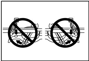
- NEVER hold workpiece on right side of blade with left hand or vice versa. This is called cross-armed cutting and exposes user to risk of SERIOUS PERSONAL INJURY as shown in the figure. ALWAYS use vise to secure workpiece.
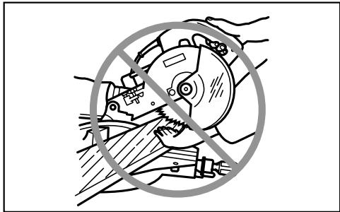
000030
- Do not abuse cord. Never yank cord to disconnect it from the receptacle. Keep cord away from heat, oil, water and sharp objects.
- NEVER stack workpieces on the table top to speed cutting operations. Cut only one piece at a time.
- Some material contains chemicals which may be toxic. Take caution to prevent dust inhalation and skin contact. Follow material
supplier safety data.
SAVE THESE INSTRUCTIONS.
WARNING:
MISUSE or failure to follow the safety rules stated in this instruction manual may cause serious personal injury.
USB088-2
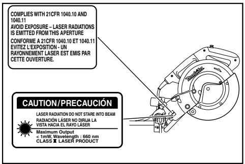
ADDITIONAL SAFETY RULES FOR THE LASER
CAUTION:
LASER RADIATION DO NOT STARE INTO BEAM.
AVOID EXPOSURE - LASER RADIATION IS EMITTED FROM APERTURE.
USE OF CONTROLS OR ADJUSTMENTS OR PERFORMANCE OF PROCEDURES OTHER THAN THOSE SPECIFIED HEREIN MAY RESULT IN HAZARDOUS RADIATION EXPOSURE.
010401
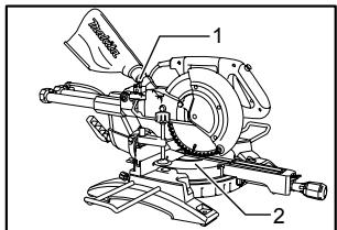
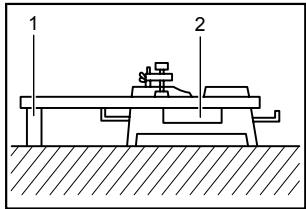
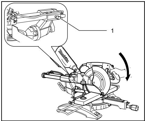
INSTALLATION
Bench mounting
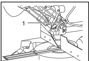
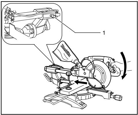
1. Stopper pin
010228
When the tool is shipped, the handle is locked in the lowered position by the stopper pin. Release the stopper pin by lowering the handle slightly and pulling the stopper pin.
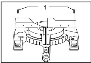
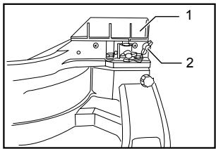
1. Bolt
010564
This tool should be bolted with four bolts to a level and stable surface using the bolt holes provided in the tool's base. This will help prevent tipping and possible injury.
FUNCTIONAL DESCRIPTION
CAUTION:
Always be sure that the tool is switched off and unplugged before adjusting or checking function on the tool.
Blade guard
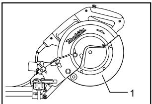
1. Blade guard
010386
When lowering the handle, the blade guard rises automatically. The blade guard returns to its original position when the cut is completed and the handle is raised. NEVER DEFEAT OR REMOVE THE BLADE GUARD OR THE SPRING WHICH ATTACHES TO THE GUARD.
In the interest of your personal safety, always maintain the blade guard in good condition. Any irregular operation of the blade guard should be corrected immediately. Check to assure spring loaded return action of guard. NEVER USE THE TOOL IF THE BLADE GUARD OR SPRING ARE DAMAGED, FAULTY OR REMOVED. DOING SO IS HIGHLY DANGEROUS AND CAN CAUSE SERIOUS PERSONAL INJURY.
If the see-through blade guard becomes dirty, or sawdust adheres to it in such a way that the blade and/or workpiece is no longer easily visible, unplug the saw and clean the guard carefully with a damp cloth. Do not use solvents or any petroleum-based cleaners on the plastic guard.
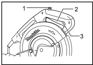
If the blade guard is especially dirty and vision through the guard is impaired, use the supplied socket wrench to loosen the hex bolt holding the center cover. Loosen the
hex bolt by turning it counterclockwise and raise the blade guard and center cover. With the blade guard so positioned, cleaning can be more completely and efficiently accomplished. When cleaning is complete, reverse procedure above and secure bolt. Do not remove spring holding blade guard. If guard becomes discolored through age or UV light exposure, contact a Makita service center for a new guard. DO NOT DEFECT OR REMOVE GUARD.
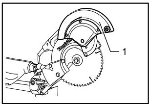
010387
1. Blade guard
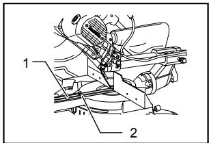
Positioning kerf board
010384
- Kerf board
- Screw
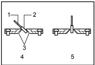
001800
- Saw blade
- Blade teeth
- Kerf board
- Left bevel cut
- Straight cut
This tool is provided with the kerf boards in the turn base to minimize tearing on the exit side of a cut. The kerf boards are factory adjusted so that the saw blade does not contact the kerf boards. Before use, adjust the kerf boards as follows:
First, unplug the tool. Loosen all the screws (3 each on left and right) securing the kerf boards. Re-tighten them only to the extent that the kerf boards can still be easily moved by hand. Lower the handle fully and push in the stopper pin to lock the handle in the lowered position. Loosen the screw which secures the slide poles. Pull the carriage toward you fully. Adjust the kerf boards so that the kerf boards just contact the sides of the blade teeth. Tighten the front screws (do not tighten firmly). Push the carriage toward the guide fence fully and adjust the kerf
boards so that the kerf boards just contact the sides of blade teeth. Tighten the rear screws (do not tighten firmly).
After adjusting the kerf boards, release the stopper pin and raise the handle. Then tighten all the screws securely.
CAUTION:
Before and after changing the bevel angle, always adjust the kerf boards as described above.
Maintaining maximum cutting capacity
Unplug the tool before any adjustment is attempted. This tool is factory adjusted to provide the maximum cutting capacity for a 255 mm (10") saw blade.
When installing a new blade, always check the lower limit position of the blade and if necessary, adjust it as follows:
010402
- Adjusting bolt
- Turn base
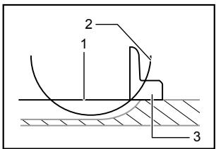
001540
- Top surface of turn base
- Periphery of blade
- Guide fence
First, unplug the tool. Push the carriage toward the guide fence fully and lower the handle completely. Use the hex wrench to turn the adjusting bolt until the periphery of the blade extends slightly below the top surface of the turn base at the point where the front face of the guide fence meets the top surface of the turn base.
With the tool unplugged, rotate the blade by hand while holding the handle all the way down to be sure that the blade does not contact any part of the lower base. Re-adjust slightly, if necessary.
CAUTION:
After installing a new blade, always be sure that the blade does not contact any part of the lower base when the handle is lowered completely. Always do this with the tool unplugged.
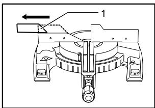
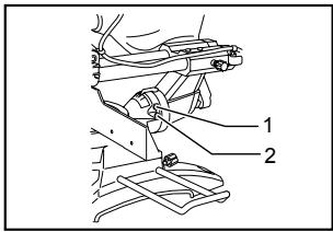
Stopper arm
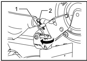
- Stopper arm
- Adjusting screw
010233
The lower limit position of the blade can be easily adjusted with the stopper arm. To adjust it, move the stopper arm in the direction of the arrow as shown in the figure. Adjust the adjusting screw so that the blade stops at the desired position when lowering the handle fully.
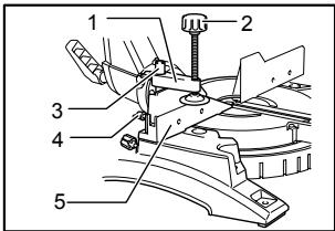
Adjusting the miter angle
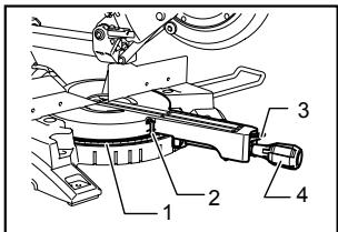
- Miter scale
- Pointer
- Lock lever
- Grip
010234
Loosen the grip by turning counterclockwise. Turn the turn base while pressing down the lock lever. When you have moved the grip to the position where the pointer points to the desired angle on the miter scale, securely tighten the grip clockwise.
CAUTION:
- When turning the turn base, be sure to raise the handle fully.
After changing the miter angle, always secure the turn base by tightening the grip firmly.
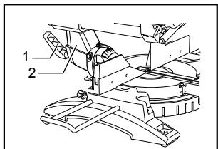
Adjusting the bevel angle
1. Lever
010236
To adjust the bevel angle, loosen the lever at the rear of the tool counterclockwise. Unlock the arm by pushing the handle somewhat strongly in the direction that you intend to tilt the saw blade.
- Lever
- Arm
- Pointer
- Bevel scale
010235
Tilt the saw blade until the pointer points to the desired angle on the bevel scale. Then tighten the lever clockwise firmly to secure the arm.

1. Lever
010236
When tilting the carriage to the right, tilt the carriage to the left slightly after loosening the lever and press the releasing button. With the releasing button being pressed, tilt the carriage to the right.
- Pointer
- Release button
- Bevel scale
010430
Tilt the saw blade until the pointer points to the desired angle on the bevel scale. Then tighten the lever clockwise firmly to secure the arm.
CAUTION:
- When tilting the saw blade, be sure to raise the handle fully.
After changing the bevel angle, always secure the arm by tightening the lever clockwise. - When changing bevel angles, be sure to position the kerf boards appropriately as explained in the "Positioning kerf boards" section.
Slide lock adjustment
- Locking screw
010428
To lock the slide pole, turn the locking screw clockwise.
Switch action
CAUTION:
Before plugging in the tool, always check to see that the switch trigger actuates properly and returns to the "OFF" position when released.
- Do not pull the switch trigger hard without pressing in the lock-off button. This can cause switch breakage.
010388
- Lock-off button
- Switch trigger
- Hole for padlock
To prevent the switch trigger from being accidentally pulled, a lock-off button is provided. To start the tool, press in the lock-off button and pull the switch trigger. Release the switch trigger to stop.
A hole is provided in the switch trigger for insertion of padlock to lock the tool off.
WARNING:
- Do not use a lock with a shank or cable any smaller than 6.35 ~mm (1/4") in diameter.
- NEVER use tool without a fully operative switch trigger. Any tool with an inoperative switch is HIGHLY DANGEROUS and must be repaired before further usage.
- For your safety, this tool is equipped with a lock-off button which prevents the tool from unintended starting. NEVER use the tool if it runs when you simply pull the switch trigger without pressing the lock-off button. Return tool to a Makita service center for proper repairs BEFORE further usage.
- NEVER tape down or defeat purpose and function of lock-off button.
Electric brake
This tool is equipped with an electric blade brake. If the tool consistently fails to quickly stop blade after switch trigger release, have tool serviced at a Makita service center.
The blade brake system is not a substitute for blade guard. NEVER USE TOOL WITHOUT A FUNCTIONING BLADE GUARD. SERIOUS PERSONAL INJURY CAN RESULT.
Electronic function
Soft start feature
- Soft start because of suppressed starting shock.
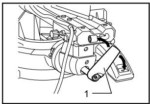
Laser beam action
For model LS1017L only
CAUTION:
-
When not in use, be sure to turn off the laser
-
Switch for laser
010257
CAUTION:
LASER RADIATION
Do not stare into beam.
Before shifting the laser line or performing maintenance adjustment, be sure to unplug the tool.
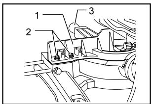
To turn on the laser beam, press the upper position (I) of the switch. Press the lower position (O) to turn off.
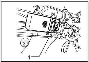
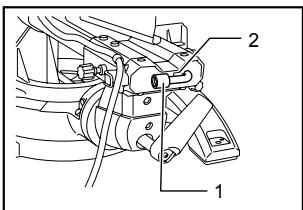
Laser line can be shifted to either the left or right side of the saw blade by loosening the screw holding the laser unit box and shifting it in the desired direction. After shifting, be sure to tighten the screw.
1. Screw holding the laser unit box 010389
Laser line is factory adjusted so that it is positioned within 1mm (0.04") from the side surface of the blade (cutting position).
Cleaning of the lens for the laser light
If the lens for the laser light becomes dirty, or sawdust adheres to it in such a way that the laser line is no longer easily visible, unplug the saw and remove and clean the lens for the laser light carefully with a damp, soft cloth. Do not use solvents or any petroleum-based cleaners on the lens.
NOTE:
- When laser line is dim and almost or entirely invisible because of the direct sunlight in the indoor or outdoor window-by work, relocate the work area to a place not exposed to the direct sunlight.
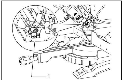
Replacing the dry cells for laser unit
010399
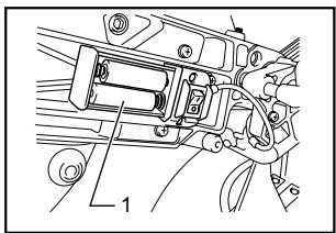
1. Dry cell
010259
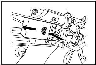
Remove the lid for the dry cells for laser unit by sliding while pressing it. Take out the old dry cells and put the
new ones as shown in the figure. After replacing, return the lid to cover it.
ASSEMBLY
CAUTION:
Always be sure that the tool is switched off and unplugged before carrying out any work on the tool.
Storage of socket wrench with hex wrench on its other end
010240
- Socket wrench with hex wrench on its other end
- Wrench holder
The socket wrench is stored as shown in the figure. When using the socket wrench, pull it out of the wrench holder. After using the socket wrench, return it to the wrench holder.
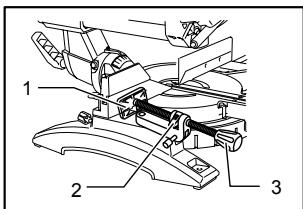
Installing or removing saw blade
CAUTION:
Always be sure that the tool is switched off and unplugged before installing or removing the blade.
Use only the Makita socket wrench provided to install or remove the blade. Failure to do so may result in overtightening or insufficient tightening of the hex bolt. This could cause an injury.

1. Stopper pin
010228
Lock the handle in the raised position by pushing in the stopper pin.
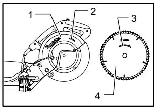
010390
-
Socket wrench
-
Blade case
-
Center cover
-
Hex bolt
-
Blade guard
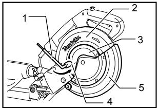
To remove the blade, use the socket wrench to loosen the hex bolt holding the center cover by turning it counterclockwise. Raise the blade guard and center cover.
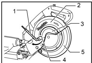
010391
- Blade case
- Socket wrench
- Hex bolt
- Arrow
- Shaft lock
Press the shaft lock to lock the spindle and use the socket wrench to loosen the hex bolt clockwise. Then remove the hex bolt, outer flange and blade.
NOTE:
- When inner flange is removed mistakenly, be sure to install it on the spindle with its protrusion facing the spindle.
010392
- Blade case
- Arrow
- Arrow
- Saw blade
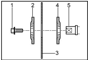
001786
- Hex bolt
- Outer flange
- Saw blade
- Inner flange
- Spindle
To install the blade, mount it carefully onto the spindle, making sure that the direction of the arrow on the surface of the blade matches the direction of the arrow on the blade case.
Install the outer flange and hex bolt, and then use the socket wrench to tighten the hex bolt (left-handed) securely counterclockwise while pressing the shaft lock.
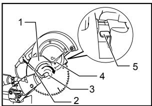
010560
- Socket wrench
- Blade case
- Center cover
- Hex bolt
5.Blade guard
Return the blade guard and center cover to its original position. Then tighten the hex bolt clockwise to secure the center cover. Release the handle from the raised position by pulling the stopper pin. Lower the handle to make sure that the blade guard moves properly. Make sure shaft lock has released spindle before making cut.
Dust bag (accessory)
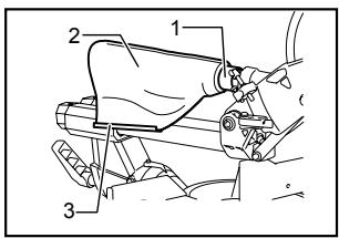
010245
- Dust nozzle
- Dust bag
- Fastener
The use of the dust bag makes cutting operations clean and dust collection easy. To attach the dust bag, fit it onto the dust nozzle.
When the dust bag is about half full, remove the dust bag from the tool and pull the fastener out. Empty the dust bag of its contents, tapping it lightly so as to remove particles adhering to the insides which might hamper further collection.
NOTE:
If you connect a vacuum cleaner to your saw, more efficient and cleaner operations can be performed.
Securing workpiece
WARNING:
It is extremely important to always secure the workpiece properly and tightly with the vise. Failure to do so can cause the tool to be damaged and/or the workpiece to be destroyed. PERSONAL INJURY MAY ALSO RESULT. Also, after a cutting operation, DO NOT raise the blade until the blade has come to a complete stop.
CAUTION:
- When cutting long workpieces, use supports that are as high as the top surface level of the turn base. Do not rely solely on the vertical vise and/or horizontal vise to secure the workpiece.
Thin material tends to sag. Support workpiece over its entire length to avoid blade pinch and possible KICKBACK.
- Support
- Turn base
001549
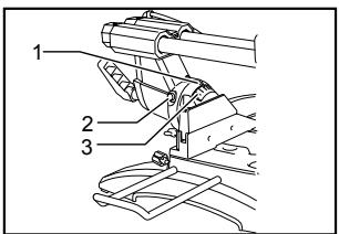
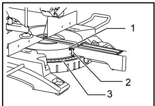
Sliding fence adjustment
- Sliding fence
- Clamping screw
010480
WARNING:
Before operating the tool, make sure that the sliding fence is secured firmly.
Before bevel-cutting, make sure that no part of the tool contacts the sliding fence when lowering and raising the handle fully at any position and pulling or pushing the carriage all the way at the lowest position..
- Sliding fence
010407
CAUTION:
- When performing bevel cuts, slide the sliding fence to the left and secure it as shown in the figure. Otherwise, it will contact the blade or a part of the tool, causing possible serious injury to the operator.
This tool is equipped with the sliding fence which should ordinarily be positioned as shown in the figure.
However, when performing left bevel cuts, set it to the left position as shown in the figure if the tool head contacts it. When bevel-cutting operations are complete, don't forget to return the sliding fence to the original position and secure it by firmly tightening the clamping screw.
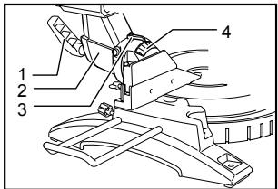
Vertical vise
- Vise arm
- Vise knob
- Vise rod
- Screw
- Guide fence
010393
The vertical vise can be installed on either the left or right side of the guide fence. Insert the vise rod into the hole in the guide fence and tighten the screw on the back of the guide fence to secure the vise rod.
Position the vise arm according to the thickness and shape of the workpiece and secure the vise arm by tightening the screw. If the screw to secure the vise arm contacts the guide fence, install the screw on the opposite side of vise arm. Make sure that no part of the tool contacts the vise when lowering the handle fully and pulling or pushing the carriage all the way. If some part contacts the vise, re-position the vise.
Press the workpiece flat against the guide fence and the turn base. Position the workpiece at the desired cutting position and secure it firmly by tightening the vise knob.
CAUTION:
- The workpiece must be secured firmly against the turn base and guide fence with the vise during all operations.
Horizontal vise (optional accessory)
- Vise plate
- Vise nut
- Vise knob
010299
The horizontal vise can be installed in two positions on either the left or right side of the base. When performing 10^ or greater miter cuts, install the horizontal vise on the side opposite the direction in which the turn base is to be turned.
005232
By flipping the vise nut to the left, the vise is released, and rapidly moves in and out. To grip the workpiece, push the vise knob forward until the vise plate contacts the workpiece and flip the vise nut to the right. Then turn the vise knob clockwise to secure the workpiece.
The maximum width of workpiece which can be secured by the horizontal vise is 215mm (8-1/2").
CAUTION:
Always rotate the vise nut to the right fully when securing the workpiece. Failure to do so may result in insufficient securing of the workpiece. This could cause the workpiece to be thrown, cause damage to the blade or cause the loss of control, which can result in PERSONAL INJURY.
- When cutting out thin workpiece, such as base boards, against the fence, always use the horizontal vise.
Holders
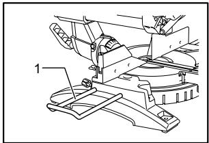
1. Holder
010255
The holders can be installed on either side as a convenient means of holding workpieces horizontally. Slip fully the holder rods into the holes in the base. Then tighten the holders securely with the screws.
CAUTION:
Always support long workpieces level with the top surface of the turn base for accurate cuts and to prevent dangerous loss of control of the tool.
OPERATION
CAUTION:
Before use, be sure to release the handle from the lowered position by pulling the stopper pin.
Make sure the blade is not contacting the workpiece, etc. before the switch is turned on.
- Do not apply excessive pressure on the handle when cutting. Too much force may result in overload of the motor and/or decreased cutting efficiency. Push down handle with only as much force as is necessary for smooth cutting and without significant decrease in blade speed.
Gently press down the handle to perform the cut. If the handle is pressed down with force or if lateral force is applied, the blade will vibrate and leave a mark (saw mark) in the workpiece and the precision of the cut will be impaired.
During a slide cut, gently push the carriage toward the guide fence without stopping. If the carriage movement is stopped during the cut, a mark will be left in the workpiece and the precision of the cut will be impaired.
1. Press cutting (cutting small workpieces)
010394
1. Locking screw
Workpieces up to 91 mm (3-5/8") high and 70 mm (2-3/4") wide can be cut in the following way.
Push the carriage toward the guide fence fully and tighten the locking screw clockwise to secure the carriage. Secure the workpiece with the vise. Switch on the tool without the blade making any contact and wait until the blade attains full speed before lowering. Then gently lower the handle to the fully lowered position to cut the workpiece. When the cut is completed, switch off the tool and WAIT UNTIL THE BLADE HAS COME TO A COMPLETE STOP before returning the blade to its fully elevated position.
CAUTION:
- Firmly tighten the knob clockwise so that the carriage will not move during operation. Insufficient tightening may cause unexpected kickback of the blade. Possible serious PERSONAL INJURY may result.
2. Slide (push) cutting (cutting wide workpieces)
1. Locking screw
010395
Loosen the locking screw counterclockwise so that the carriage can slide freely. Secure the workpiece with the vise. Pull the carriage toward you fully. Switch on the tool without the blade making any contact and wait until the blade attains full speed. Press down the handle and PUSH THE CARRIAGE TOWARD THE GUIDE FENCE AND THROUGH THE WORKPIECE. When the cut is completed, switch off the tool and WAIT UNTIL THE BLADE HAS COME TO A COMPLETE STOP before returning the blade to its fully elevated position.
CAUTION:
- Whenever performing the slide cut, FIRST PULL THE CARRIAGE TOWARD YOU FULLY and press down the handle to the fully lowered position, then PUSH THE CARRIAGE TOWARD THE GUIDE FENCE. NEVER START THE CUT WITH THE CARRIAGE NOT FULLY PULLED TOWARD YOU. If you perform the slide cut without pulling the carriage fully or if you perform the slide cut toward your direction, the blade may kickback unexpectedly with the potential to cause serious PERSONAL INJURY.
-
Never perform the slide cut with the handle locked in the lowered position by pressing the stopper pin.
-
Never loosen the locking screw which secures the carriage while the blade is rotating. This may cause serious injury.
3. Miter cutting
Refer to the previously covered "Adjusting the miter angle".
4. Bevel cut
010396
Loosen the lever and tilt the saw blade to set the bevel angle (Refer to the previously covered "Adjusting the bevel angle"). Be sure to retighten the lever firmly to secure the selected bevel angle safely. Secure the workpiece with a visse. Make sure the carriage is pulled all the way back toward the operator. Switch on the tool without the blade making any contact and wait until the blade attains full speed. Then gently lower the handle to the fully lowered position while applying pressure in parallel with the blade and PUSH THE CARRIAGE TOWARD THE GUIDE FENCE TO CUT THE WORKPIECE. When the cut is completed, switch off the tool and WAIT UNTIL THE BLADE HAS COME TO A COMPLETE STOP before returning the blade to its fully elevated position.
CAUTION:
Always be sure that the blade will move down to bevel direction during a bevel cut. Keep hands out of path of saw blade.
During a bevel cut, it may create a condition whereby the piece cut off will come to rest against the side of the blade. If the blade is raised while the blade is still rotating, this piece may be caught by the blade, causing fragments to be scattered which is dangerous. The blade should be raised ONLY after the blade has come to a complete stop.
- When pressing down the handle, apply pressure in parallel with the blade. If a force is applied perpendicularly to the turn base or if the pressure direction is changed during a cut, the precision of the cut will be impaired.
Always slide the sliding fence so that it does not interfere any part of the carriage when performing bevel cuts.
5. Compound cutting
Compound cutting is the process in which a bevel angle is made at the same time in which a miter angle is being cut on a workpiece. Compound cutting can be performed at angle shown in the table.
| Miter angle | Bevel angle |
| Left and Right 0° - 45° | Left 0° - 45° |
010340
When performing compound cutting, refer to "Press cutting", "Slide cutting", "Miter cutting" and "Bevel cut" explanations.
6. Cutting crown and cove moldings
Crown and cove moldings can be cut on a compound miter saw with the moldings laid flat on the turn base.
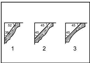
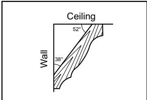
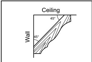
There are two common types of crown moldings and one type of cove moldings; 52 / 38^ wall angle crown molding, 45^ wall angle crown molding and 45^ wall angle cove molding. See illustrations.
001555
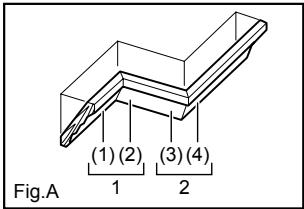
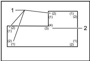
There are crown and cove molding joints which are made to fit "Inside" 90^ corners ((1) and (2) in Fig. A) and "Outside" 90^ corners ((3) and (4) in Fig. A).
001556
001557
-
52 / 38^ type crown molding
2.45° type crown molding
3.45° type cove molding -
Inside corner
-
Outside corner
-
Inside corner
- Outside corner
Measuring
Measure the wall length and adjust workpiece on table to cut wall contact edge to desired length. Always make sure that cut workpiece length at the back of the workpiece is the same as wall length. Adjust cut length for angle of cut. Always use several pieces for test cuts to check the saw angles.
When cutting crown and cove moldings, set the bevel angle and miter angle as indicated in the table (A) and position the moldings on the top surface of the saw base as indicated in the table (B).
In the case of left bevel cut
Table (A)
| Molding position in Fig. A | Bevel angle | Miter angle | |||
| 52/38° type | 45° type | 52/38° type | 45° type | ||
| For inside corner | (1) | Left 33.9° | Left 30° | Right 31.6° | Right 35.3° |
| (2) | Left 31.6° | Left 35.3° | |||
| For outside corner | (3) | ||||
| (4) | Right 31.6° | Right 35.3° | |||
006361
Table (B)
| Molding position in Fig. A | Molding edge against guide fence | Finished piece | |
| For inside corner | (1) | Ceiling contact edge should be against guide fence. | Finished piece will be on the Left side of blade. |
| (2) | Wall contact edge should be against guide fence. | ||
| For outside corner | (3) | Finished piece will be on the Right side of blade. | |
| (4) | Ceiling contact edge should be against guide fence. |
006362
Example:
In the case of cutting 52 / 38^ type crown molding for position (1) in Fig. A:
- Tilt and secure bevel angle setting to 33.9^ LEFT.
- Adjust and secure miter angle setting to 31.6^ RIGHT.
- Lay crown molding with its broad back (hidden) surface down on the turn base with its CEILING CONTACT EDGE against the guide fence on the saw.
The finished piece to be used will always be on the LEFT side of the blade after the cut has been made.
Compound Miter Saw Miter and Bevel Angle Settings
000031
Wall to Crown Molding Angle: 52/38 degrees
| Wall Angle (deg.) | Bevel Angle (deg.) | Miter Angle (deg.) |
| 60 | 43.0 | 46.8 |
| 61 | 42.8 | 46.3 |
| 62 | 42.5 | 45.7 |
| 63 | 42.2 | 45.1 |
| 64 | 41.9 | 44.6 |
| 65 | 41.7 | 44.0 |
| 66 | 41.4 | 43.5 |
| 67 | 41.1 | 42.9 |
| 68 | 40.8 | 42.4 |
| 69 | 40.5 | 41.9 |
| 70 | 40.2 | 41.3 |
| 71 | 39.9 | 40.8 |
| 72 | 39.6 | 40.3 |
| 73 | 39.3 | 39.8 |
| 74 | 39.0 | 39.2 |
| 75 | 38.7 | 38.7 |
| 76 | 38.4 | 38.2 |
| 77 | 38.1 | 37.7 |
| 78 | 37.8 | 37.2 |
| 79 | 37.4 | 36.8 |
| 80 | 37.1 | 36.3 |
| 81 | 36.8 | 35.8 |
| 82 | 36.5 | 35.3 |
| 83 | 36.2 | 34.8 |
| 84 | 35.8 | 34.4 |
| 85 | 35.5 | 33.9 |
| 86 | 35.2 | 33.4 |
| 87 | 34.9 | 33.0 |
| 88 | 34.5 | 32.5 |
| 89 | 34.2 | 32.1 |
| 90 | 33.9 | 31.6 |
| 91 | 33.5 | 31.2 |
| 92 | 33.2 | 30.7 |
| 93 | 32.8 | 30.3 |
| 94 | 32.5 | 29.9 |
| 95 | 32.2 | 29.4 |
| 96 | 31.8 | 29.0 |
| 97 | 31.5 | 28.6 |
| 98 | 31.1 | 28.2 |
| 99 | 30.8 | 27.7 |
| 100 | 30.4 | 27.3 |
| Wall Angle (deg.) | Bevel Angle (deg.) | Miter Angle (deg.) |
| 101 | 30.1 | 26.9 |
| 102 | 29.7 | 26.5 |
| 103 | 29.4 | 26.1 |
| 104 | 29.0 | 25.7 |
| 105 | 28.7 | 25.3 |
| 106 | 28.3 | 24.9 |
| 107 | 28.0 | 24.5 |
| 108 | 27.6 | 24.1 |
| 109 | 27.2 | 23.7 |
| 110 | 26.9 | 23.3 |
| 111 | 26.5 | 22.9 |
| 112 | 26.1 | 22.6 |
| 113 | 25.8 | 22.2 |
| 114 | 25.4 | 21.8 |
| 115 | 25.0 | 21.4 |
| 116 | 24.7 | 21.0 |
| 117 | 24.3 | 20.7 |
| 118 | 23.9 | 20.3 |
| 119 | 23.6 | 19.9 |
| 120 | 23.2 | 19.6 |
| 121 | 22.8 | 19.2 |
| 122 | 22.5 | 18.8 |
| 123 | 22.1 | 18.5 |
| 124 | 21.7 | 18.1 |
| 125 | 21.3 | 17.8 |
| 126 | 21.0 | 17.4 |
| 127 | 20.6 | 17.1 |
| 128 | 20.2 | 16.7 |
| 129 | 19.8 | 16.4 |
| 130 | 19.5 | 16.0 |
| 131 | 19.1 | 15.7 |
| 132 | 18.7 | 15.3 |
| 133 | 18.3 | 15.0 |
| 134 | 17.9 | 14.6 |
| 135 | 17.6 | 14.3 |
| 136 | 17.2 | 14.0 |
| 137 | 16.8 | 13.6 |
| 138 | 16.4 | 13.3 |
| 139 | 16.0 | 13.0 |
| 140 | 15.6 | 12.8 |
| Wall Angle(deg.) | Bevel Angle(deg.) | Miter Angle(deg.) |
| 141 | 15.3 | 12.3 |
| 142 | 14.9 | 12.0 |
| 143 | 14.5 | 11.6 |
| 144 | 14.1 | 11.3 |
| 145 | 13.7 | 11.0 |
| 146 | 13.3 | 10.7 |
| 147 | 12.9 | 10.3 |
| 148 | 12.5 | 10.0 |
| 149 | 12.2 | 9.7 |
| 150 | 11.8 | 9.4 |
| 151 | 11.4 | 9.0 |
| 152 | 11.0 | 8.7 |
| 153 | 10.8 | 8.4 |
| 154 | 10.2 | 8.1 |
| 155 | 9.8 | 7.8 |
| 156 | 9.4 | 7.5 |
| 157 | 9.0 | 7.1 |
| 158 | 8.6 | 6.8 |
| 159 | 8.3 | 6.5 |
| 160 | 7.9 | 6.2 |
| 161 | 7.5 | 5.9 |
| 162 | 7.1 | 5.6 |
| 163 | 6.7 | 5.3 |
| 164 | 6.3 | 4.9 |
| 165 | 5.9 | 4.6 |
| 166 | 5.5 | 4.3 |
| 167 | 5.1 | 4.0 |
| 168 | 4.7 | 3.7 |
| 169 | 4.3 | 3.4 |
| 170 | 3.9 | 3.1 |
| 171 | 3.5 | 2.8 |
| 172 | 3.2 | 2.5 |
| 173 | 2.8 | 2.2 |
| 174 | 2.4 | 1.8 |
| 175 | 2.0 | 1.5 |
| 176 | 1.6 | 1.2 |
| 177 | 1.2 | 0.9 |
| 178 | 0.8 | 0.6 |
| 179 | 0.4 | 0.3 |
| 180 | 0.0 | 0.0 |
Compound Miter Saw Miter and Bevel Angle Settings
000032
Wall to Crown Molding Angle: 45 degrees
| Wall Angle (deg.) | Bevel Angle (deg.) | Miter Angle (deg.) |
| 60 | 37.8 | 50.8 |
| 61 | 37.5 | 50.2 |
| 62 | 37.3 | 49.6 |
| 63 | 37.1 | 49.1 |
| 64 | 36.8 | 48.5 |
| 65 | 36.6 | 48.0 |
| 66 | 36.4 | 47.4 |
| 67 | 36.1 | 46.9 |
| 68 | 35.9 | 46.4 |
| 69 | 35.6 | 45.8 |
| 70 | 35.4 | 45.3 |
| 71 | 35.1 | 44.8 |
| 72 | 34.9 | 44.2 |
| 73 | 34.6 | 43.7 |
| 74 | 34.4 | 43.2 |
| 75 | 34.1 | 42.7 |
| 76 | 33.9 | 42.1 |
| 77 | 33.6 | 41.6 |
| 78 | 33.3 | 41.1 |
| 79 | 33.1 | 40.6 |
| 80 | 32.8 | 40.1 |
| 81 | 32.5 | 39.6 |
| 82 | 32.3 | 39.1 |
| 83 | 32.0 | 38.6 |
| 84 | 31.7 | 38.1 |
| 85 | 31.4 | 37.7 |
| 86 | 31.1 | 37.2 |
| 87 | 30.9 | 36.7 |
| 88 | 30.6 | 36.2 |
| 89 | 30.3 | 35.7 |
| 90 | 30.0 | 35.3 |
| 91 | 29.7 | 34.8 |
| 92 | 29.4 | 34.3 |
| 93 | 29.1 | 33.9 |
| 94 | 28.8 | 33.4 |
| 95 | 28.5 | 32.9 |
| 96 | 28.2 | 32.5 |
| 97 | 27.9 | 32.0 |
| 98 | 27.6 | 31.6 |
| 99 | 27.3 | 31.1 |
| 100 | 27.0 | 30.7 |
| Wall Angle (deg.) | Bevel Angle (deg.) | Miter Angle (deg.) |
| 101 | 26.7 | 30.2 |
| 102 | 26.4 | 29.8 |
| 103 | 26.1 | 29.4 |
| 104 | 25.8 | 28.9 |
| 105 | 25.5 | 28.5 |
| 106 | 25.2 | 28.1 |
| 107 | 24.9 | 27.6 |
| 108 | 24.6 | 27.2 |
| 109 | 24.2 | 26.8 |
| 110 | 23.9 | 26.3 |
| 111 | 23.6 | 25.9 |
| 112 | 23.3 | 25.5 |
| 113 | 23.0 | 25.1 |
| 114 | 22.7 | 24.7 |
| 115 | 22.3 | 24.3 |
| 116 | 22.0 | 23.8 |
| 117 | 21.7 | 23.4 |
| 118 | 21.4 | 23.0 |
| 119 | 21.0 | 22.6 |
| 120 | 20.7 | 22.2 |
| 121 | 20.4 | 21.8 |
| 122 | 20.0 | 21.4 |
| 123 | 19.7 | 21.0 |
| 124 | 19.4 | 20.6 |
| 125 | 19.1 | 20.2 |
| 126 | 18.7 | 19.8 |
| 127 | 18.4 | 19.4 |
| 128 | 18.1 | 19.0 |
| 129 | 17.7 | 18.6 |
| 130 | 17.4 | 18.2 |
| 131 | 17.1 | 17.9 |
| 132 | 16.7 | 17.5 |
| 133 | 16.4 | 17.1 |
| 134 | 16.0 | 16.7 |
| 135 | 15.7 | 16.3 |
| 136 | 15.4 | 15.9 |
| 137 | 15.0 | 15.6 |
| 138 | 14.7 | 15.2 |
| 139 | 14.3 | 14.8 |
| 140 | 14.0 | 14.4 |
| Wall Angle (deg.) | Bevel Angle (deg.) | Miter Angle (deg.) |
| 141 | 13.7 | 14.1 |
| 142 | 13.3 | 13.7 |
| 143 | 13.0 | 13.3 |
| 144 | 12.6 | 12.9 |
| 145 | 12.3 | 12.6 |
| 146 | 11.9 | 12.2 |
| 147 | 11.6 | 11.8 |
| 148 | 11.2 | 11.5 |
| 149 | 10.9 | 11.1 |
| 150 | 10.5 | 10.7 |
| 151 | 10.2 | 10.4 |
| 152 | 9.8 | 10.0 |
| 153 | 9.5 | 9.6 |
| 154 | 9.2 | 9.3 |
| 155 | 8.8 | 8.9 |
| 156 | 8.5 | 8.5 |
| 157 | 8.1 | 8.2 |
| 158 | 7.8 | 7.8 |
| 159 | 7.4 | 7.5 |
| 160 | 7.1 | 7.1 |
| 161 | 6.7 | 6.7 |
| 162 | 6.4 | 6.4 |
| 163 | 6.0 | 6.0 |
| 164 | 5.6 | 5.7 |
| 165 | 5.3 | 5.3 |
| 166 | 4.9 | 5.0 |
| 167 | 4.6 | 4.6 |
| 168 | 4.2 | 4.3 |
| 169 | 3.9 | 3.9 |
| 170 | 3.5 | 3.5 |
| 171 | 3.2 | 3.2 |
| 172 | 2.8 | 2.8 |
| 173 | 2.5 | 2.5 |
| 174 | 2.1 | 2.1 |
| 175 | 1.8 | 1.8 |
| 176 | 1.4 | 1.4 |
| 177 | 1.1 | 1.1 |
| 178 | 0.7 | 0.7 |
| 179 | 0.4 | 0.4 |
| 180 | 0.0 | 0.0 |
7. Cutting aluminum extrusion
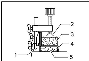
010404
- Guide fence
- Vise
- Spacer block
- Aluminum extrusion
- Spacer block
010469
- Aluminum extrusion
- Guide fence
- Spacer block
- Horizontal vise (optional accessory)
CAUTION:
When securing aluminum extrusions, use spacer blocks or pieces of scrap as shown in the figure to prevent deformation of the aluminum. Use a cutting lubricant when cutting the aluminum extrusion to prevent build-up of the aluminum material on the blade.
- Never attempt to cut thick or round aluminum extrusions. Thick aluminum extrusions may come loose during operation and round aluminum extrusions cannot be secured firmly with this tool.
8. Wood facing
Use of wood facing helps to assure splinter-free cuts in workpieces. Attach a wood facing to the guide fence using the holes in the guide fence. See the figure concerning the dimensions for a suggested wood facing.
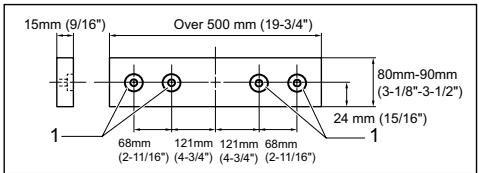
010535
1. Holes
CAUTION:
Use straight wood of even thickness as the wood facing.
Use screws to attach the wood facing to the guide fence. The screws should be installed so that the
screw heads are below the surface of the wood facing.
- When the wood facing is attached, do not turn the turn base with the handle lowered. The blade and/or the wood facing will be damaged.
9. Groove cutting
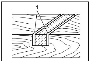
1. Cut grooves with blade
001563
A dado type cut can be made by proceeding as follows:
Adjust the lower limit position of the blade using the adjusting screw and the stopper arm to limit the cutting depth of the blade. Refer to "Stopping arm" section described previously.
After adjusting the lower limit position of the blade, cut parallel grooves across the width of the workpiece using a slide (push) cut as shown in the figure. Then remove the workpiece material between the grooves with a chisel. Do not attempt to perform this type of cut using wide (thick) blades or with a dado blade. Possible loss of control and injury may result.
CAUTION:
- Be sure to return the stopper arm to the original position when performing other than groove cutting.
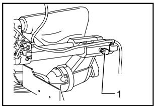
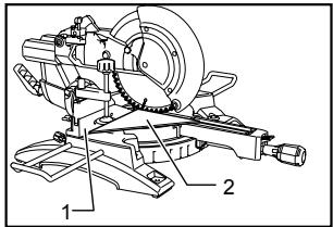
Carrying tool
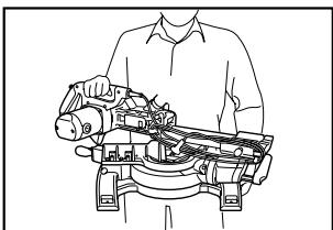
010397
Make sure that the tool is unplugged. Secure the blade at 0^ bevel angle and the turn base at right miter angle fully. Secure the slide poles after pulling the carriage toward you fully. Lower the handle fully and lock it in the lowered position by pushing in the stopper pin.
Wind the power supply cord using the cord rests.
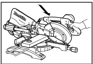
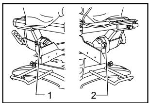
Carry the tool by holding the tool base as shown in the figure. If you remove the holders, dust bag, etc., you can carry the tool more easily.
Carry the tool by holding both sides of the tool base as shown in the figure. If you remove the holders, dust bag, etc., you can carry the tool more easily.
CAUTION:
Always secure all moving portions before carrying the tool.
- Stopper pin is for carrying and storage purposes only and not for any cutting operations.
MAINTENANCE
CAUTION:
Always be sure that the tool is switched off and unplugged before attempting to perform inspection or maintenance.
WARNING:
Always be sure that the blade is sharp and clean for the best and safest performance.
NOTICE:
- Never use gasoline, benzine, thinner, alcohol or the like. Discoloration, deformation or cracks may result.
Adjusting the cutting angle
This tool is carefully adjusted and aligned at the factory, but rough handling may have affected the alignment. If your tool is not aligned properly, perform the following:
1. Miter angle
010251
- Guide fence
- Hex bolts
- Grip
Push the carriage toward the guide fence and tighten the locking screw to secure the carriage. Loosen the grip which secures the turn base. Turn the turn base so that the pointer points to 0^ on the miter scale. Then turn the turn base slightly clockwise and counterclockwise to seat the turn base in the 0^ miter notch. (Leave as it is if the pointer does not point to 0^ .) Loosen the hex sockets bolts securing the guide fence using the socket wrench.
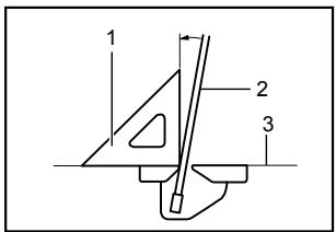
010398
- Guide fence
- Triangular rule
Lower the handle fully and lock it in the lowered position by pushing in the stopper pin. Square the side of the blade with the face of the guide fence using a triangular rule, try-square, etc. Then securely tighten the hex socket bolts on the guide fence in the order from the right side.
010432
- Screw
- Pointer
- Miter scale
Make sure that the pointer points to 0^ on the miter scale. If the pointer does not point to 0^ , loosen the screw which secures the pointer and adjust the pointer so that it will point to 0^ .
2. Bevel angle
(1) 0^ bevel angle
010260
- Lever
- Arm
Push the carriage toward the guide fence and tighten the locking screw to secure the carriage. Lower the handle fully and lock it in the lowered position by pushing in the stopper pin. Loosen the lever at the rear of the tool.
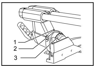
010482
1.0° adjusting bolt
2. Left 45^ bevel angle adjusting bolt
Turn the hex bolt on the right side of the arm two or three revolutions counterclockwise to tilt the blade to the right.
001819
- Triangular rule
- Saw blade
- Top surface of turn base
Carefully square the side of the blade with the top surface of the turn base using the triangular rule, try-square, etc. by turning the hex bolt on the right side of the arm clockwise. Then tighten the lever securely.
010261
- Screw
- Pointer
- Bevel scale
Make sure that the pointer on the arm point to 0^ on the bevel scale on the arm holder. If they do not point to 0^ , loosen the screw which secure the pointer and adjust it so that it will point to 0^ .
(2) 45^ bevel angle
010483
- Right 5^ bevel angle adjusting bolt
- Left 45^ bevel angle adjusting bolt
Adjust the 45^ bevel angle only after performing 0^ bevel angle adjustment. To adjust left 45^ bevel angle, loosen the lever and tilt the blade to the left fully. Make sure that the pointer on the arm points to 45^ on the bevel scale on the arm holder. If the pointer does not point to 45^ , turn the 45^ bevel angle adjusting bolt on the right side of the arm holder until the pointer points to 45^ . To adjust the right 5^ bevel angle, perform the same procedure as that described above.
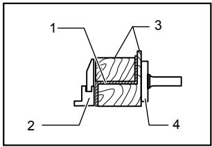
Replacing carbon brushes
007834
Remove and check the carbon brushes regularly. Replace when they wear down to 3mm in length. Keep the carbon brushes clean and free to slip in the holders. Both carbon brushes should be replaced at the same time. Use only identical carbon brushes.
Use a screwdriver to remove the brush holder caps. Take out the worn carbon brushes, insert the new ones and secure the brush holder caps.

010256
- Screwdriver
- Brush holder cap
After replacing brushes, plug in the tool and break in brushes by running tool with no load for about 10 minutes. Then check the tool while running and electric brake operation when releasing the switch trigger. If electric brake is not working well, ask your local Makita service center for repair.
After use
After use, wipe off chips and dust adhering to the tool with a cloth or the like. Keep the blade guard clean according to the directions in the previously covered section titled "Blade guard". Lubricate the sliding portions with machine oil to prevent rust.
- When storing the tool, pull the carriage toward you fully.
To maintain product SAFETY and RELIABILITY, repairs, any other maintenance or adjustment should be performed by Makita Authorized or Factory Service Centers, always using Makita replacement parts.
ACCESSORIES
CAUTION:
These accessories or attachments are recommended for use with your Makita tool specified in this manual. The use of any other accessories or attachments might present a risk of injury to persons. Only use accessory or attachment for its stated purpose.
If you need any assistance for more details regarding these accessories, ask your local Makita Service Center.
Steel & Carbide-tipped saw blades
| Miter saw blades | For smooth and precise cutting in various materials. |
| Combination | General purpose blade for fast and smooth rip, crosscuts and miters. |
| Crosscutting | For smoother cross grain cuts. Slices cleanly against the grain. |
| Fine cross cuts | For sand-free cuts cleanly against the grain. |
| Non-ferrous metals miter saw blades | For miters in aluminum, copper, brass, tubing, and other non-ferrous metals. |
006526
Vise assembly (Horizontal vise)
Vertical vise
- Socket wrench with hex wrench on its other end
Holder
Dust bag
Elbow
Triangular rule
MAKITA LIMITED ONE YEAR WARRANTY
Warranty Policy
Every Makita tool is thoroughly inspected and tested before leaving the factory. It is warranted to be free of defects from workmanship and materials for the period of ONE YEAR from the date of original purchase. Should any trouble develop during this one year period, return the COMPLETE tool, freight prepaid, to one of Makita's Factory or Authorized Service Centers. If inspection shows the trouble is caused by defective workmanship or material, Makita will repair (or at our option, replace) without charge.
This Warranty does not apply where:
- repairs have been made or attempted by others:
- repairs are required because of normal wear and tear:
the tool has been abused, misused or improperly maintained:
alterations have been made to the tool.
IN NO EVENT SHALL MAKITA BE LIABLE FOR ANY INDIRECT, INCIDENTAL OR CONSEQUENTIAL DAMAGES FROM THE SALE OR USE OF THE PRODUCT. THIS DISCLAIMER APPLIES BOTH DURING AND AFTER THE TERM OF THIS WARRANTY.
MAKITA DISCLAIMS LIABILITY FOR ANY IMPLIED WARRANTYES, INCLUDING IMPLIED WARRANTYES OF "MERCHANTABILITY" AND "FITNESS FOR A SPECIFIC PURPOSE," AFTER THE ONE YEAR TERM OF THIS WARRANTY.
This Warranty gives you specific legal rights, and you may also have other rights which vary from state to state. Some states do not allow the exclusion or limitation of incidental or consequential damages, so the above limitation or exclusion may not apply to you. Some states do not allow limitation on how long an implied warranty lasts, so the above limitation may not apply to you.
EN0006-1
(32-1/2" x 21-1/8" x 22-7/8")
Poids net
19,4 kg (42,8 lbs)
Some dust created by power sanding, sawing, grinding, drilling, and other construction activities contains chemicals known to the State of California to cause cancer, birth defects or other reproductive harm. Some examples of these chemicals are:
- lead from lead-based paints,
crystalline silica from bricks and cement and other masonry products, and - arsenic and chromium from chemically-treated lumber.
Your risk from these exposures varies, depending on how often you do this type of work. To reduce your exposure to these chemicals: work in a well ventilated area, and work with approved safety equipment, such as those dust masks that are specially designed to filter out microscopic particles.
< USA solamente >
ADVERTENCIA
3-11-8, Sumiyoshi-cho,
Anjo, Aichi 446-8502 Japan

- ENGLISH (Original instructions)
- SPECIFICATIONS
- For Your Own Safety Read Instruction Manual
- Before Operating Tool
- Save it for future reference
- GENERAL SAFETY PRECAUTIONS
- (For All Tools)
- ADDITIONAL SAFETY RULES
- SAVE THESE INSTRUCTIONS.
- WARNING:
- ADDITIONAL SAFETY RULES FOR THE LASER
- CAUTION:
- INSTALLATION
- Bench mounting
- FUNCTIONAL DESCRIPTION
- Blade guard
- Maintaining maximum cutting capacity
- Stopper arm
- Adjusting the miter angle
- Adjusting the bevel angle
- Slide lock adjustment
- Switch action
- Electric brake
- Electronic function
- Soft start feature
- Laser beam action
- For model LS1017L only
- Cleaning of the lens for the laser light
- NOTE:
- Replacing the dry cells for laser unit
- ASSEMBLY
- Storage of socket wrench with hex wrench on its other end
- Installing or removing saw blade
- Dust bag (accessory)
- Securing workpiece
- WARNING:
- Sliding fence adjustment
- Vertical vise
- Horizontal vise (optional accessory)
- Holders
- OPERATION
- Press cutting (cutting small workpieces)
- Locking screw
- Slide (push) cutting (cutting wide workpieces)
- Miter cutting
- Bevel cut
- Compound cutting
- Cutting crown and cove moldings
- Measuring
- In the case of left bevel cut
- Example:
- Compound Miter Saw Miter and Bevel Angle Settings
- Cutting aluminum extrusion
- Wood facing
- Holes
- Groove cutting
- Carrying tool
- MAINTENANCE
- NOTICE:
- Adjusting the cutting angle
- Miter angle
- Bevel angle
- Replacing carbon brushes
- After use
- ACCESSORIES
- MAKITA LIMITED ONE YEAR WARRANTY
- Warranty Policy
- ADVERTENCIA
Brand : MAKITA
Model : LS1017L
Category : Miter saw