
PowerConnect 7024P - Network switch DELL - Free user manual and instructions
Find the device manual for free PowerConnect 7024P DELL in PDF.


| Product Type | Layer 3 Gigabit Stackable Network Switch |
| Model | Dell PowerConnect 7024P (PC7024P) |
| Number of Ports | 24 ports 10/100/1000 BASE-T PoE+ (30 W per port) + 4 combo SFP ports |
| PoE Standard | IEEE 802.3at-2009 (PoE+) |
| Total PoE Budget | 720 W with internal AC power supply only, up to 1440 W with external MPS1000 power supply |
| Internal Power Supply | 1000 W AC (100-240 V, 50-60 Hz) |
| Redundant External Power Supply | Dell PowerConnect MPS1000 (1000 W) |
| Dimensions (W × D × H) | 440 × 460 × 44 mm (17.3 × 18.1 × 1.74 in) |
| Approximate Weight | 8 kg (17.6 lb) |
| Mounting | 19-inch rack mountable (1U) or standalone on a flat surface |
| Stacking | Up to 12 switches, ring topology (stacking modules optional) |
| Console Port | RJ-45 (DTE), baud rate 9600, 8 bits, 1 stop bit, no parity |
| Out-of-Band Management Port | 1 dedicated Ethernet 10/100/1000 BASE-T port |
| USB Port | 1 USB 2.0 type A port (FAT32 read/write) |
| Main Features | VLAN, Spanning Tree, dynamic routing (layer 3), multicast, QoS, ACL, SNMP |
| Cooling | 2 fans + 1 in power supply unit |
| Operating Temperature | 0 to 45 °C |
| Relative Humidity | 95% non-condensing |
| Maintenance and Cleaning | Unplug before cleaning; use a dry, lint-free cloth; do not use liquid or abrasive products |
| Safety | Use a grounded power cord; do not block ventilation openings; follow the safety manual instructions |
| Spare Parts and Repairability | Replaceable internal power supply (MPS1000 optional), hot-swappable expansion modules (10G, SFP+, stacking); no user-serviceable parts inside |
Frequently Asked Questions - PowerConnect 7024P DELL
User questions about PowerConnect 7024P DELL
0 question about this device. Answer the ones you know or ask your own.
Ask a new question about this device
Download the instructions for your Network switch in PDF format for free! Find your manual PowerConnect 7024P - DELL and take your electronic device back in hand. On this page are published all the documents necessary for the use of your device. PowerConnect 7024P by DELL.
USER MANUAL PowerConnect 7024P DELL
Notes, Cautions, and Warnings

NOTE: A NOTE indicates important information that helps you make better use of your computer.

CAUTION: A CAUTION indicates potential damage to hardware or loss of data if instructions are not followed.

WARNING: A WARNING indicates a potential for property damage, personal injury, or death.
Information in this publication is subject to change without notice.
© 2011 Dell Inc. All rights reserved.
Reproduction of these materials in any manner whatsoever without the written permission of Dell Inc. is strictly forbidden.
Trademarks used in this text: Dell™, the DELL logo, PowerConnect™, and OpenManage™ are trademarks of Dell Inc. Microsoft®, Windows®, Windows Server®, MS-DOS® and Windows Vista® are either trademarks or registered trademarks of Microsoft Corporation in the United States and/or other countries.
Other trademarks and trade names may be used in this publication to refer to either the entities claiming the marks and names or their products. Dell Inc. disclaims any proprietary interest in trademarks and trade names other than its own.
Regulatory Models: PC7024, PC7024P, PC7024F, PC7048, PC7048P, PC7048R, and PC7048R-RA
Contents
1 Introduction.... 5
PowerConnect 7000 Series Overview. . . . . . . . . . . 5
2 Hardware Overview....6
PowerConnect 7000 Series Front Panel. . . . . . . . . . 6
Switch Ports 9
Console Port 9
Out-of-Band Management Port ..... 10
USB Port 10
Reset Button 10
Port and System LEDs 10
Stack Master LED and Stack
Number Display. 11
PowerConnect 7000 Series Back Panel. . . . . . . . 11
Expansion Slots for Plug-in Modules. . . . . . . 12
Power Supplies 12
Ventilation System 13
Locator LED....13
3 Installation.... 14
Site Preparation 14
Unpacking the Switch 14
Package Contents. 14
Unpacking Steps 15
Mounting the Switch. 15
Installing in a Rack 15
Installing as a Free-standing Switch ..... 17
Stacking Multiple Switches.... 17
Creating a Switch Stack 17
4 Starting and Configuring the Switch... 19
Connecting a Switch to a Terminal 20
Connecting a Switch to a Power Supply 22
AC and DC Power Connection 22
Booting the Switch. 23
Performing the Initial Configuration. 23
Enabling Remote Management....24
Initial Configuration Procedure....24
Example Session 25
Next Steps 29
5 PoE Power Budget.... 30
Introduction
This document provides basic information about the Dell PowerConnect 7000 Series switches, including how to install a switch and perform the initial configuration. For information about how to configure and monitor switch features, see the User's Configuration Guide, which is available on your User Documentation CD, or check the Dell Support website at support.dell.com for the latest updates on documentation and firmware.
This document contains the following sections:
- Hardware Overview
- Installation
- Starting and Configuring the Switch
PowerConnect 7000 Series Overview
The PowerConnect 7000 Series switches are stackable Layer 3 Gigabit Ethernet switches and include the following six models:
• PowerConnect 7024 (PC7024)
• PowerConnect 7024P (PC7024P)
• PowerConnect 7024F (PC7024F)
• PowerConnect 7048 (PC7048)
• PowerConnect 7048P (PC7048P)
• PowerConnect 7048R (PC7048R/PC7048R-RA)

NOTE: The PowerConnect 7048R (PC7048R/PC7048R-RA) is a top-of-rack switch. The difference between the PC7048R and PC7048R-RA models is the air-flow direction.
Hardware Overview
This section contains information about device characteristics and modular hardware configurations for the PowerConnect 7000 Series switches.
All models are 1U, rack mountable switches with the following physical dimensions:
- 440 × 460 × 44 ~mm (W × D × H) .
- 17.3 x 18.1 x 1.7 inch (W x D x H).
PowerConnect 7000 Series Front Panel
The following images show the front panels of the six switch models in the PowerConnect 7000 Series.
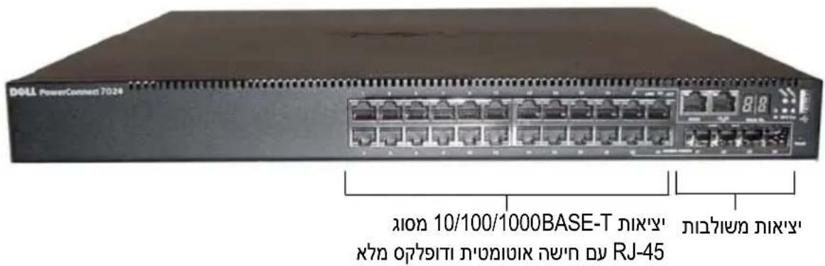
Figure 1-1. PowerConnect 7024 with 24 10/100/1000BASE-T Ports
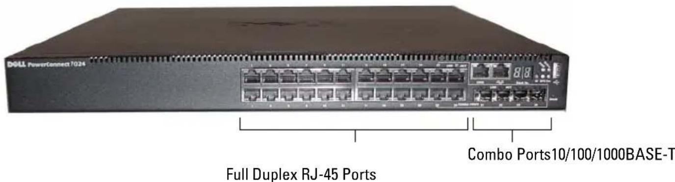
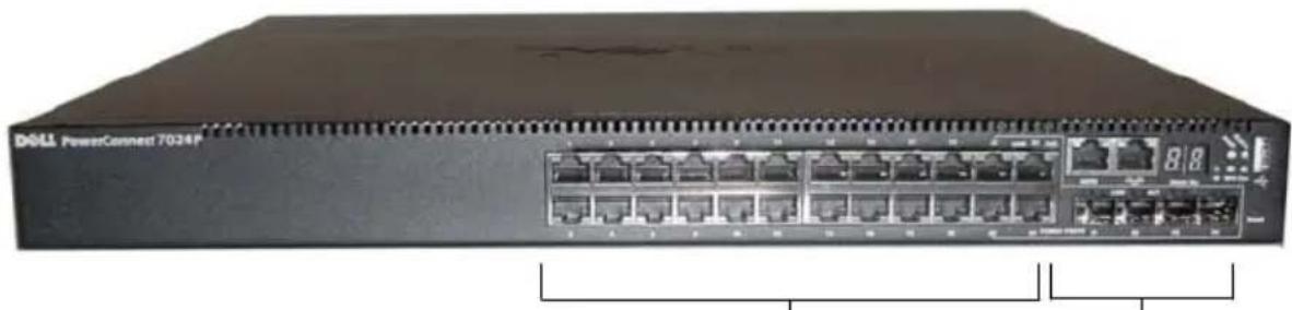
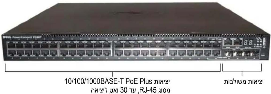
Figure 1-2. PowerConnect 7024P with 24 10/100/1000BASE-T PoE Plus Ports
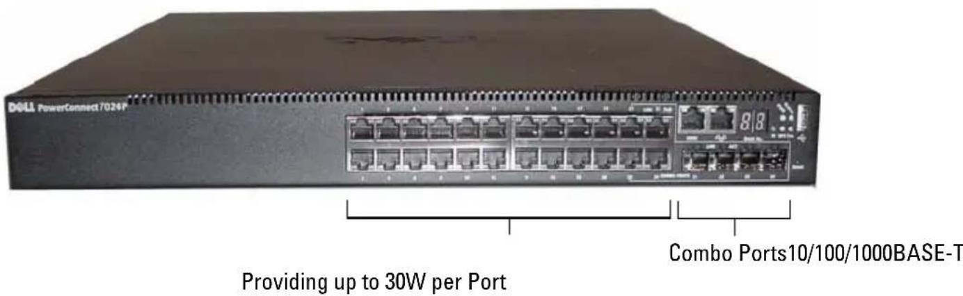
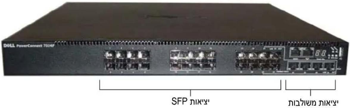
Figure 1-3. PowerConnect 7024F with 24 SFP Ports
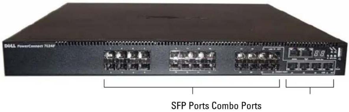
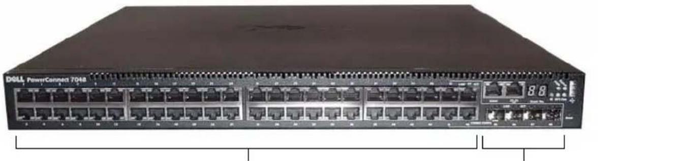
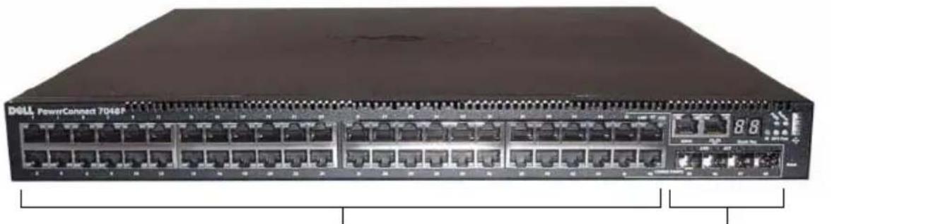
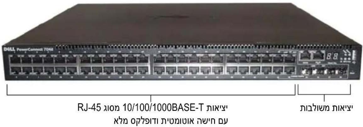
Figure 1-4. PowerConnect 7048 with 48 10/100/1000BASE-T Ports
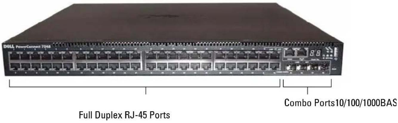
Figure 1-5. PowerConnect 7048P with 48 10/100/1000BASE-T PoE Plus Ports
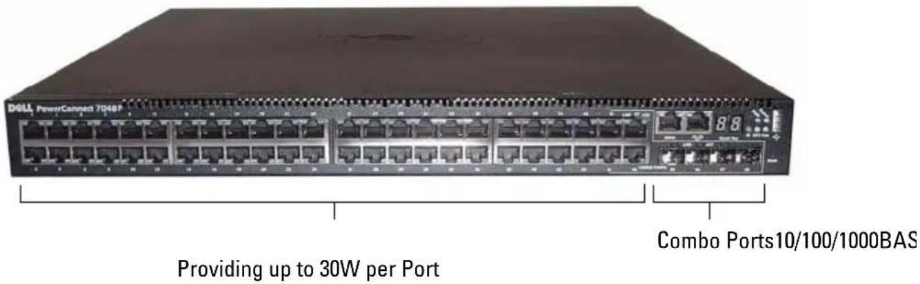
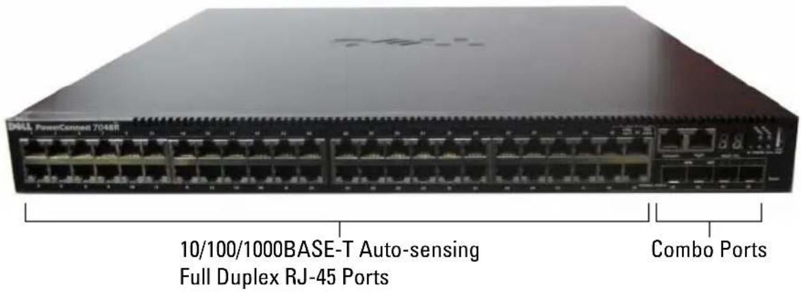
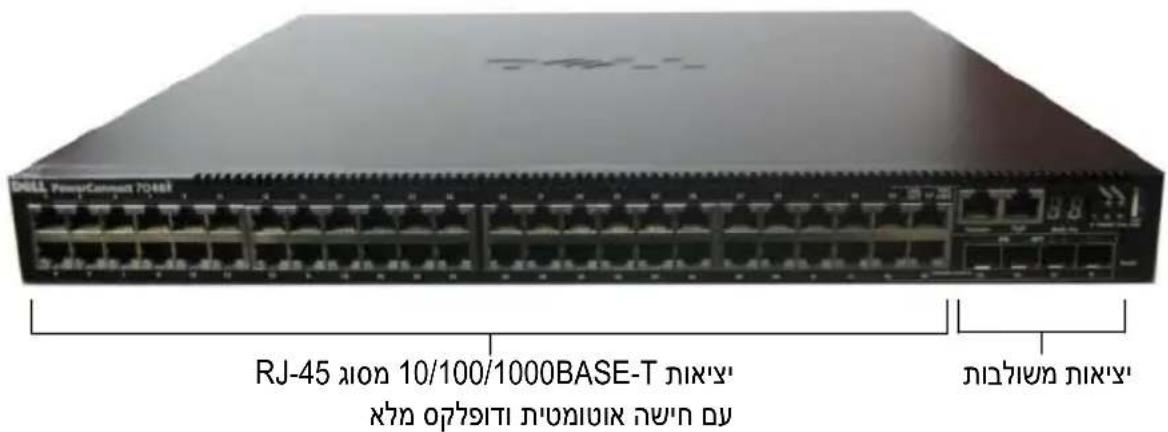
Figure 1-6. PowerConnect 7048R with 48 10/100/1000BASE-T Ports
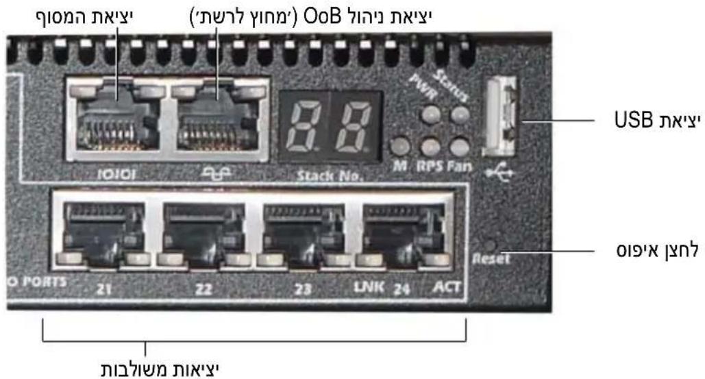
In addition to the switch ports, the front panel of each model in the series includes the following ports:
- Console port
• Out-of-band management port - USB port
The additional ports are on the right side of the front panel.
Figure 1-7. Additional PowerConnect 7000 Series Ports
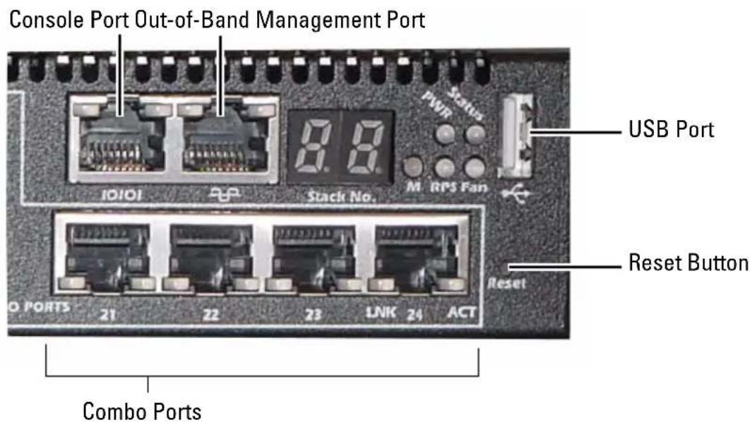
The front panel also contains a reset button (pinhole) and several status LEDs.

NOTE: The port LEDs and system LEDs on the front panel are not the same for all models. Figure 1-7 shows the LEDs on the PowerConnect 7024, PowerConnect 7024F, and PowerConnect 7048 switches.
Switch Ports
The PowerConnect 7024 and PowerConnect 7024P front panel provides 24 Gigabit Ethernet (10/100/1000BASE-T) RJ-45 ports with four SFP combo ports that have an auto-sensing mode for speed, flow control, and duplex mode. SFP transceivers are sold separately. The PowerConnect 7024P switch ports are IEEE 802.3at-2009-compliant (PoE Plus) and can be provided up to 30W of power per port.
The PowerConnect 7024F front panel provides 20 Gigabit Ethernet (10/100/1000BASE-FX) SFP ports plus 4 combo ports for copper or SFP media support.
The PowerConnect 7048, PowerConnect 7048P, and PowerConnect 7048R front panel provides 48 Gigabit Ethernet (10/100/1000BASE-T) RJ-45 ports with four SFP combo ports. The PowerConnect 7048P switch ports are IEEE 802.3at-2009-compliant (PoE Plus) and can provide up to 30W of power per port.
The front-panel switch ports have the following characteristics:
- The switch automatically detects the difference between crossed and straight-through cables on RJ-45 ports.
- SFP ports support both SX and LX modules.
- RJ-45 ports support half- and full-duplex mode 10/100/1000 Mbps.
Console Port
The console port is for management through a serial interface. This port provides a direct connection to the switch and allows you to access the CLI from a console terminal connected to the port through the provided serial cable (RJ-45 to female DB-9 connectors).
The console port supports asynchronous data of eight data bits, one stop bit, no parity bit, and no flow control. The default baud rate is 9600 bps.
Out-of-Band Management Port
The Out-of-Band (OOB) management port is a 10/100/1000BASE-T Ethernet port dedicated to remote switch management. Traffic on this port is segregated from operational network traffic on the switch ports and cannot be switched or routed to the operational network.
USB Port
The Type-A, female USB port supports a USB 2.0-compliant flash memory drive. The PowerConnect switch can read or write to a flash drive formatted as FAT-32. You can use a USB flash drive to copy switch configuration files and images between the USB flash drive and the switch. You can also use the USB flash drive to move and copy configuration files and images from one switch to other switches in the network.
The USB port does not support any other type of USB device.
Reset Button
The reset button is accessed through the pinhole and allows you to perform a hard reset on the switch. To use the reset button, insert an unbent paper clip or similar tool into the pinhole. When the switch completes the boot process after the reset, it resumes operation with the most recently saved configuration. Any changes made to the running configuration that were not saved to the startup configuration prior to the reset are lost.
Port and System LEDs
The front panel contains light emitting diodes (LEDs) that indicate the status of port links, power supplies, fans, stacking, and the overall system. Additionally, the PowerConnect 7024P and PowerConnect 7048P switches contain LEDs that provide information about Power over Ethernet Plus (PoE+) status and activity on the ports.
For information about the status that the LEDs indicate, see the User's Configuration Guide.
Stack Master LED and Stack Number Display
When a switch within a stack is the master unit, the stack master LED, which is labeled M, is solid green. If the M LED is off, the stack member is not the master unit. The Stack No. panel displays the unit number for the stack member. If a switch is not part of a stack, the M LED is illuminated and the stack unit number is 1.
PowerConnect 7000 Series Back Panel
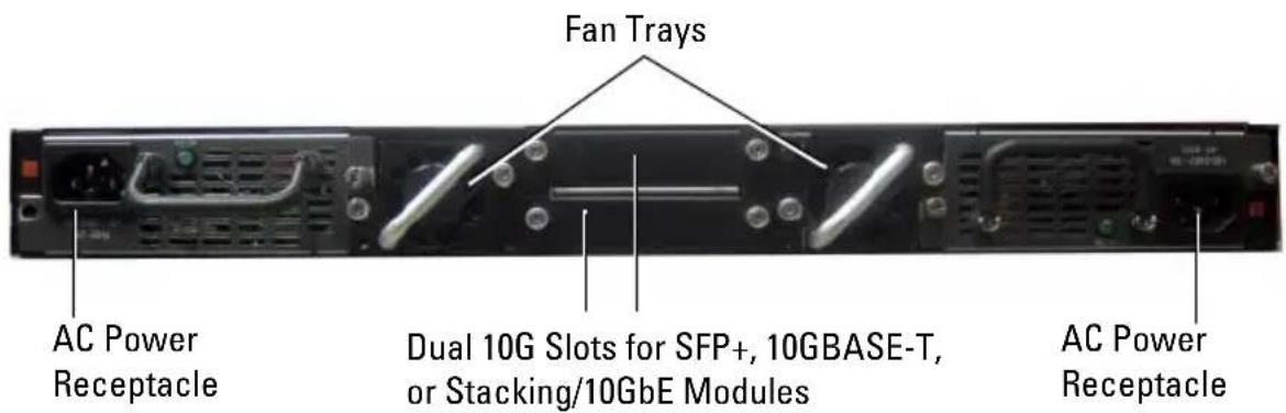
The following images show the back panel of the PowerConnect 7000 Series switches.
Figure 1-8. PC7024, PC7024F, and PC7048 Back Panel
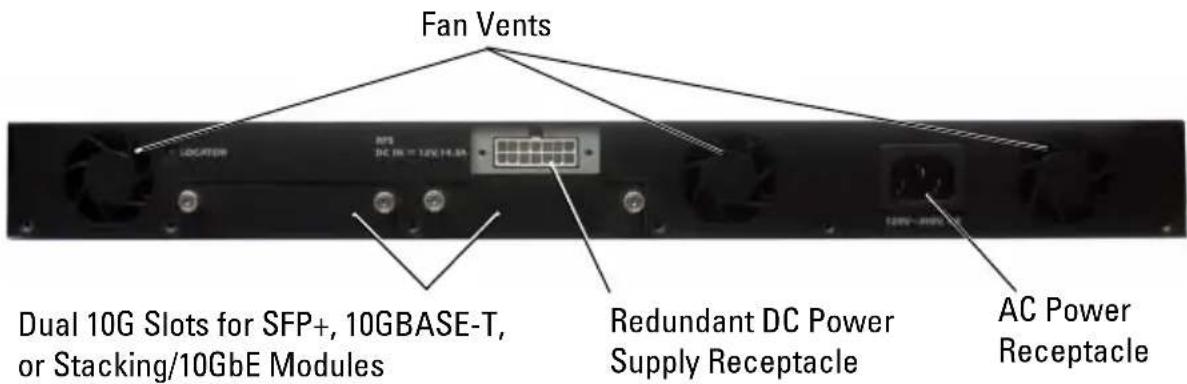
Figure 1-9. PC7024P and PC7048P Back Panel
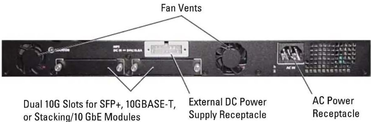
Figure 1-10. PC7048R Back Panel
Expansion Slots for Plug-in Modules
Two expansion slots are located on the back of the switch and can support the following modules:
- 10GBASE-T module
- SFP+ module
- Stacking/10 GbE module
Each plug-in module has two ports. The Stacking/10GbE modules can be configured to operate as either 16-Gigabit stacking ports or 10-Gigabit Ethernet switch ports. The plug-in modules include hot-swap support, so you do not need to reboot the switch after you install a new module.
Power Supplies
PC7024 and PC7024F
PowerConnect 7024 and PowerConnect 7024F switches have an internal 180-watt power supply. The additional external power supply (PowerConnect RPS720) provides 180 watts of power and gives full redundancy for the switch.
PC7024P
PowerConnect 7024P switches have an internal 1000-watt power supply. The additional external power supply (PowerConnect MPS1000) provides 1000 Watts and gives full redundancy for the switch.
PC7048
PowerConnect 7048 switches have an internal 180-watt power supply. The additional external power supply (PowerConnect RPS720) provides 180 watts and gives full redundancy for the switch.
PC7048P
PowerConnect 7048P switches have an internal 1000-watt power supply which can support up to 24 ports of PoE. The additional external power supply (PowerConnect MPS1000) allows all 48 ports of PoE, or 24 ports of PoE and full redundancy for the switch.
PC7048R and PC7048R-RA
PowerConnect 7048R and PowerConnect 7048R-RA switches are designed as top-of-rack switches and include two internal, replaceable, AC power supplies for redundant or load-sharing operation. Each power supply can provide 300 watts and includes hot-swap support. This means you do not need to power-down the switch to remove or replace one power supply while the other power supply is operating normally. However, it is necessary to remove power from the power supply that is being removed or replaced.

CAUTION: Remove the power cable from the modules prior to removing the module itself. Power must not be connected prior to insertion in the chassis.
Ventilation System
Three fans cool the PowerConnect 7024, PowerConnect 7024F, and PowerConnect 7048. The PowerConnect 7024P and PowerConnect 7048P each have two fans, with a third fan in the internal power supply. The PowerConnect 7048R has two hot-swappable fan trays with one fan each.
Locator LED
The back panel includes an LED to help identify the switch within a rack or room full of switches. From your remote management system, you can set the LED to blink to help you or a local technician identify the physical location of the switch.
Installation
Site Preparation
PowerConnect 7000 Series switches can be mounted in a standard 48.26-cm (19-inch) rack or left freestanding (placed on a flat surface) and function as stand-alone switches.
Before installing the switch or switches, make sure that the chosen installation location meets the following site requirements:
- Power — The switch is installed near an easily accessible 100–240 VAC, 50–60 Hz outlet.
- Clearance — There is adequate front and rear clearance for operator access. Allow clearance for cabling, power connections, and ventilation.
- Cabling — The cabling is routed to avoid sources of electrical noise such as radio transmitters, broadcast amplifiers, power lines, and fluorescent lighting fixtures.
- Ambient Temperature — The ambient switch operating temperature range is 0 to 45°C (32 to 113°F) at a relative humidity of up to 95 percent, non-condensing.
Unpacking the Switch
Package Contents
When unpacking each switch, make sure that the following items are included:
- One PowerConnect switch
- One AC power cable (two AC power cables for the PowerConnect 7048R)
• One RJ-45 to DB-9 female cable - One rack-mount kit for rack installation (two mounting brackets, bolts, and cage nuts)
-
One set of self-adhesive rubber pads for the free-standing switch (four pads are included)
• User Documentation CD -
Getting Started Guide
• Safety and Regulatory Information
• Warranty and Support Information - Software License Agreement
Unpacking Steps

NOTE: Before unpacking the switch, inspect the container and immediately report any evidence of damage.
1 Place the container on a clean, flat surface and cut all straps securing the container.
2 Open the container or remove the container top.
3 Carefully remove the switch from the container and place it on a secure and clean surface.
4 Remove all packing material.
5 Inspect the product and accessories for damage.
Mounting the Switch

WARNING: Read the safety information in the Safety and Regulatory Information as well as the safety information for other switches that connect to or support the switch.
The AC power connector is on the back panel of the switch.
Installing in a Rack

WARNING: Do not use rack mounting kits to suspend the switch from under a table or desk, or attach it to a wall.

CAUTION: Disconnect all cables from the switch before continuing. Remove all self-adhesive pads from the underside of the switch, if they have been attached.

CAUTION: When mounting multiple switches into a rack, mount the switches from the bottom up.
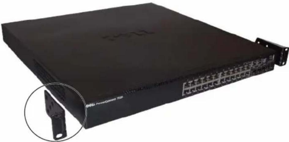
1 Place the supplied rack-mounting bracket on one side of the switch, ensuring that the mounting holes on the switch line up to the mounting holes in the rack-mounting bracket. Figure 1-11 illustrates where to mount the brackets.
Figure 1-11. Attaching the Brackets
natural_image
Black Dell PowerClosed 702 rack device with a close-up inset showing a metal bracket (no visible text or symbols on the device body)2 Insert the supplied bolts into the rack-mounting holes and tighten with a screwdriver.
3 Repeat the process for the rack-mounting bracket on the other side of the switch.
4 Insert the switch into the 48.26 cm (19 inch) rack, ensuring that the rack-mounting holes on the switch line up to the mounting holes in the rack.
5 Secure the switch to the rack with either the rack bolts or cage nuts and cage-nut bolts with washers (depending on the kind of rack you have). Fasten the bolts on bottom before fastening the bolts on top.

CAUTION: Make sure that the supplied rack bolts fit the pre-threaded holes in the rack.

NOTE: Make sure that the ventilation holes are not obstructed.
Installing as a Free-standing Switch

NOTE: We strongly recommend mounting the switch in a rack.
Install the switch on a flat surface if you are not installing it in a rack. The surface must be able to support the weight of the switch and the switch cables. The switch is supplied with four self-adhesive rubber pads.
1 Attach the self-adhesive rubber pads on each location marked on the bottom of the switch.
2 Set the switch on a flat surface, and make sure that it has proper ventilation by leaving 5 cm (2 inches) on each side and 13 cm (5 inches) at the back.
Stacking Multiple Switches
You can stack PowerConnect PowerConnect 7000 Series switches up to 12 switches high, supporting up to 576 front panel ports. When multiple switches are connected together through the stack ports, they operate as a single unit with a larger port count. The stack operates and is managed as a single entity.

NOTE: If you are installing a stack of switches, you need to assemble and cable the stack before powering up and configuring it. When a stack is powered up for the first time, the switches elect a Master Switch, which may occupy any location in the stack. The Master LED on the front panel is illuminated on the master unit.
Creating a Switch Stack
Create a stack by connecting adjacent units using the stacking ports on the back panel of the switch. Stacking modules are sold separately. Figure 1-12 shows the switches connected in a ring topology, which is the recommended topology for a stack.
1 Install a separately purchased stacking module in one of the rear expansion slots for each of the switches in the stack.
2 Connect one of the short stacking cables into either of the stacking ports of the top switch and the switch directly below it.
If necessary, use a separately purchased, long (3 meter) stacking cable to connect the switches.
3 Repeat this process until all of the devices are connected.
4 Use the remaining stacking cable to connect the remaining free ports, one each on the top and bottom switches.
Figure 1-12. Connecting a Stack of Switches
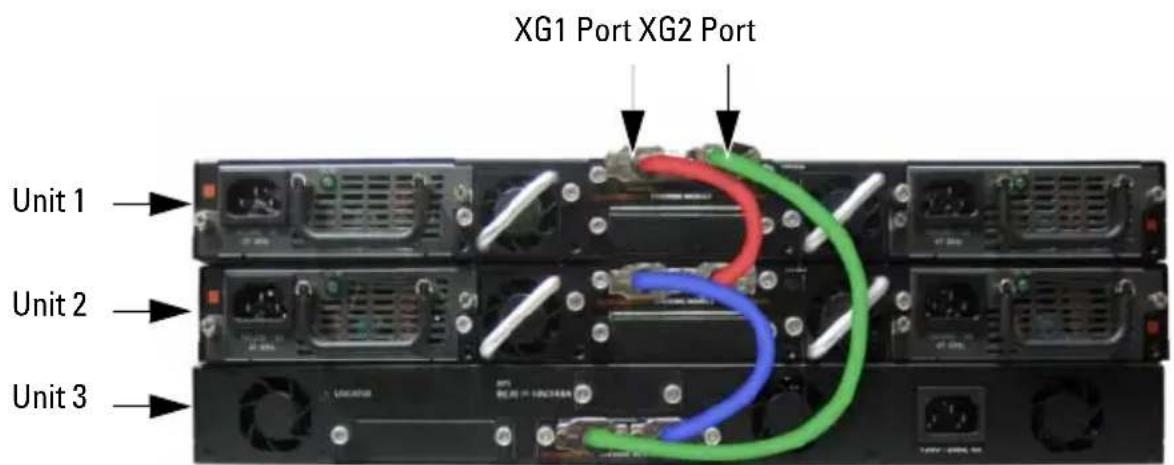
The stack in Figure 1-12 is connected in a ring topology and has the following physical connections between the switches:
- The XG1 port on Unit 1 is connected to the XG2 port on Unit 2.
- The XG1 port on Unit 2 is connected to the XG4 port on Unit 3.
• The XG3 port on Unit 3 is connected to the XG2 port on Unit 1.
Stacking Standby
The stacking feature supports a Standby or backup unit that assumes the Master unit role if the Master unit in the stack fails. As soon as a Master failure is detected in the stack, the Standby unit initializes the control plane and enables all other stack units with the current configuration. The Standby unit maintains a synchronized copy of the running configuration for the stack. During switchover, all the ports are brought down and brought up to avoid possible loops and to get new master software applications to a consistent state.
The Standby unit is pre-configured in the stack; however, you can use the CLI to select a different stack member as Standby. See the User's Configuration Guide or the CLI Reference Guide for more information.
Starting and Configuring the Switch
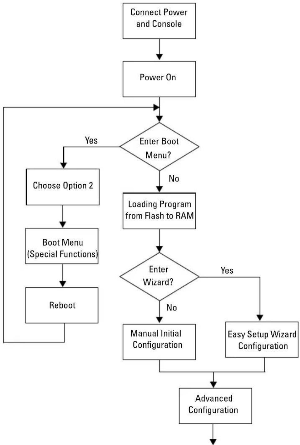
The following flow chart provides an overview of the steps you use to perform the initial configuration after the switch is unpacked and mounted.
Figure 1-13. Installation and Configuration Flow Chart
flowchart
graph TD
    A["Connect Power and Console"] --> B["Power On"]
    B --> C{Enter Boot Menu?}
    C -->|Yes| D["Choose Option 2"]
    C -->|No| E["Loading Program from Flash to RAM"]
    D --> F["Boot Menu (Special Functions)"]
    F --> G["Reboot"]
    E --> H{Enter Wizard?}
    H -->|Yes| I["Manual Initial Configuration"]
    H -->|No| J["Easy Setup Wizard Configuration"]
    I --> K["Advanced Configuration"]
    J --> K
Connecting a Switch to a Terminal
After completing all external connections, connect a terminal to a switch to configure the switch.

NOTE: Read the release notes for this product before proceeding. You can download the release notes from the Dell Support website at support.dell.com/manuals.

NOTE: We recommend that you obtain the most recent version of the user documentation from the Dell Support website at support.dell.com/manuals.
To monitor and configure the switch via serial console, use the console port on the front panel of the switch (see Figure 1-14) to connect it to a VT100 terminal or to a computer running VT100 terminal emulation software. The console port is implemented as a data terminal equipment (DTE) connector.
The following equipment is required to use the console port:
- VT100-compatible terminal or a desktop or a portable computer with a serial port running VT100 terminal emulation software, such as Microsoft HyperTerminal.
- A serial cable (provided) with an RJ-45 connector for the console port and DB-9 connector for the terminal.
Perform the following tasks to connect a terminal to the switch console port:
1 Connect the DB-9 connector on the serial cable to the terminal or computer running VT100 terminal emulation software.
2 Configure the terminal emulation software as follows:
a Select the appropriate serial port (for example, COM 1) to connect to the console.
b Set the data rate to 9600 baud.
c Set the data format to 8 data bits, 1 stop bit, and no parity.
d Set the flow control to none.
e Set the terminal emulation mode to VT100.
f Select Terminal keys for Function, Arrow, and Ctrl keys. Make sure that the setting is for Terminal keys (not Microsoft Windows keys).

NOTE: When using HyperTerminal with Microsoft Windows 2000, make sure that you have Windows 2000 Service Pack 2 or later installed. With Windows 2000 Service Pack 2, the arrow keys function properly in HyperTerminal's VT100 emulation. Go to microsoft.com for more information about Windows 2000 service packs.
3 Connect the RJ-45 connector on the cable directly to the switch console port. The PowerConnect 7000 Series console port is located on the right side of the front panel and is labeled with a |O|O| symbol, as shown in Figure 1-14.

NOTE: If you are configuring a stack of switches, connect the serial cable to the console port of the Master switch. If you connect the terminal to a subordinate switch, you will not be able to use the CLI.
Figure 1-14. Console Port Location
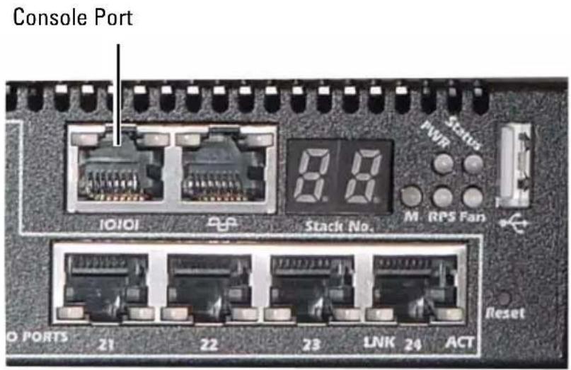
The RJ-45 port to the right of the console port is for out-of-band management.
Connecting a Switch to a Power Supply

CAUTION: Read the safety information in the Safety and Regulatory Information as well as the safety information for other switches that connect to or support the switch.
The PowerConnect 7048R switch has two power supplies for redundant or load-sharing operation. All other models in the PowerConnect 7000 Series have one power supply. The power receptacles are on the back panel.
AC and DC Power Connection
1 Make sure that the switch console port is connected to a VT100 terminal or VT100 terminal emulator via the RJ-45 to DB-9 female cable.
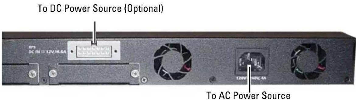
2 Using a 5-foot (1.5 m) standard power cable with safety ground connected, connect the power cable to the AC main receptacle located on the back panel (see Figure 1-15).
3 Connect the power cable to a grounded AC outlet.
4 If you are using a redundant or external DC power supply, such as the PowerConnect RPS720 or PowerConnect MPS1000, connect the DC power cable to the DC receptacle located on the back panel (see Figure 1-15).
Figure 1-15. AC and DC Power Connection to Switch
Booting the Switch
When the power is turned on with the local terminal already connected, the switch goes through a power-on self-test (POST). POST runs every time the switch is initialized and checks hardware components to determine if the switch is fully operational before completely booting. If POST detects a critical problem, the program flow stops. If POST passes successfully, valid firmware is loaded into RAM. POST messages are displayed on the terminal and indicate test success or failure. The boot process runs for approximately 60 seconds.
You can invoke the Boot menu after the first part of the POST is completed. From the Boot menu, you can perform configuration tasks such as resetting the system to factory defaults, activating the backup image, or recovering a password. For more information about the Boot menu functions, see the CLI Reference Guide.
Performing the Initial Configuration
The initial configuration procedure is based on the following assumptions:
- The PowerConnect switch was never configured before and is in the same state as when you received it.
- The PowerConnect switch booted successfully.
- The console connection was established, and the Dell Easy Setup Wizard prompt appears on the screen of a VT100 terminal or terminal equivalent.
The initial switch configuration is performed through the console port. After the initial configuration, you can manage the switch from the already-connected console port or remotely through an interface defined during the initial configuration.

NOTE: The switch is not configured with a default user name, password, or IP address.
Before setting up the initial configuration of the switch, obtain the following information from your network administrator:
- The IP address to be assigned to the management interface.
- The IP subnet mask for the network.
- The IP address of the management interface default gateway.
These settings are necessary to allow the remote management of the switch through Telnet (Telnet client) or HTTP (Web browser).
Enabling Remote Management
The front panel contains a Gigabit Ethernet port for remote out-of-band (OOB) management. The OOB port is located to the right of the console port. Additionally, you can use any of the switch ports on the front panel for in-band management. By default, all in-band ports are members of VLAN 1.
The Dell Easy Setup Wizard includes prompts to configure network information for both the OOB management interface and the VLAN 1 routing interface. For either management interface, you can assign a static IP address and subnet mask or enable DIICP and allow a network DIICP server to assign the information.
See the CLI Reference Guide for information about the CLI commands you use to configure network information.
Initial Configuration Procedure
You can perform the initial configuration by using the Dell Easy Setup Wizard or by using the CLI. The wizard automatically starts when the switch configuration file is empty. You can exit the wizard at any point by entering [ctrl+z] , but all configuration settings specified will be discarded, and the switch will use the default values.

NOTE: If you do not run the Easy Setup Wizard or do not respond to the initial Easy Setup Wizard prompt within 60 seconds, the switch enters CLI mode.
For more information about performing the initial configuration by using the CLI, see the CLI Reference Guide. This Getting Started Guide shows how to use the Easy Setup Wizard for initial switch configuration. The wizard sets up the following configuration on the switch:
- Establishes the initial privileged user account with a valid password. The wizard configures one privileged user account during the setup.
- Enables CLI login and HTTP access to use the local authentication setting only.
- Sets up the IP address for the OOB management interface.
- Sets up the IP address for the VLAN 1 routing interface, of which all in-band ports are members.
- Sets up the SNMP community string to be used by the SNMP manager at a given IP address. You may choose to skip this step if SNMP management is not used for this switch.
- Allows you to specify the network management system IP address or permit management access from all IP addresses.
- Configures the default gateway IP address for the VLAN 1 interface.
Example Session
This section describes an Easy Setup Wizard session. The following values are used by the example session:
- The SNMP community string to be used is public.
- The network management system (NMS) IP address is 10.1.2.100.
- The user name is admin, and the password is admin123.
- The OOB management interface uses DHCP for IP address assignment.
- The IP address for the VLAN 1 routing interface is 10.1.1.200 with a subnet mask of 255.255.255.0.
• The default gateway is 10.1.1.1
The setup wizard configures the initial values as defined above. After completing the wizard, the switch is configured as follows:
- SNMPv2 is enabled and the community string is set up as defined above. SNMPv3 is disabled by default.
- The admin user account is set up as defined.
- A network management system is configured. From the management station, you can access the SNMP, HTTP, and CLI interfaces. You may also choose to allow all IP addresses to access these management interfaces by choosing the (0.0.0.0) IP address.
- DHCP is enabled on the OOB management interface.
- An IP address is configured for the VLAN 1 routing interface.
- A default gateway address is configured.

NOTE: In the example below, the possible user options or default values are enclosed in []. If you press
The following example contains the sequence of prompts and responses associated with running an example Dell Easy Setup Wizard session, using the input values listed above.
After the switch completes the POST and is booted, the following dialog appears:
Unit 1 - Waiting to select management unit) >
Applying Global configuration, please wait ...
Welcome to Dell Easy Setup Wizard
The Setup Wizard guides you through the initial switch configuration, and gets you up and running as quickly as possible. You can skip the setup wizard, and enter CLI mode to manually configure the switch. You must respond to the next question to run the setup wizard within 60 seconds, otherwise the system will continue with normal operation using the default system configuration. Note: You can exit the setup wizard at any point by entering [ctrl+z].
Would you like to run the setup wizard (you must answer this question within 60 seconds)? [Y/N] y
Step 1:
The system is not setup for SNMP management by default. To manage the switch using SNMP (required for Dell Network Manager) you can
. Set up the initial SNMP version 2 account now.
. Return later and setup other SNMP accounts. (For more information on setting up an SNMP version 1 or 3 account, see the user documentation).
Would you like to setup the SNMP management interface now? [Y/N] y
To setup the SNMP management account you must specify the management system IP address and the "community string" or password that the particular management system uses to access the switch. The wizard automatically assigns the highest access level [Privilege Level 15] to this account. You can use Dell Network Manager or other management interfaces to change this setting, and to add additional management system information later. For more information on adding management systems, see the user documentation.
To add a management station:
Please enter the SNMP community string to be used.

NOTE: If it is configured, the default access level is set to the highest available access for the SNMP management interface. Initially only SNMPv2 will be activated. SNMPv3 is disabled until you return to configure security access for SNMPv3 (e.g. engine ID, view, etc.).
Please enter the IP address of the Management System (A.B.C.D) or wildcard (0.0.0.0) to manage from any Management Station. 0.0.0.0: 10.1.2.100
Step 2:
Now we need to setup your initial privilege (Level 15) user account. This account is used to login to the CLI and Web interface. You may setup other accounts and change privilege levels later. For more information on setting up user accounts and changing privilege levels, see the user documentation.
To setup a user account:
Please enter the user name. root:admin
Please enter the user password: *****
Please reenter the user password: *********
Step 3:
Next, IP addresses are setup on the OOB (Out-Of-Band) Interface and/or the VLAN 1 routing interface.
You can use these IP addresses to access the CLI, Web interface, or SNMP interface of the switch.
To access the switch through any Management Interface you can
. Setup the IP address for the Management Interface.
. Setup the default gateway if IP address is manually configured on both routing and OOB interface.
Would you like to setup the Out-Of-Band interface now? [Y/N] y
Please enter the IP address of the device (A.B.C.D) or enter "DHCP" (without the quotes) to automatically request an IP address from the network DHCP server.
Step 4:
Would you like to setup the VLAN1 routing interface now? [Y/N] y
Please enter the IP address of the device (A.B.C.D) or enter "DHCP" (without the quotes) to automatically request an IP address from the network DHCP server:
10.1.1.200
Please enter the IP subnet mask (A.B.C.D or /nn):
255.255.255.0
Step 5:
Finally, setup the default gateway. Please enter the IP address of the gateway from which this network is reachable. 0.0.0.0: 10.1.1.1
This is the configuration information that has been collected:
SNMP Interface = "public"@10.1.2.100
User Account setup = admin
Password = *****
Out-of-band IP address = DHCP
VLAN1 Router Interface IP = 10.1.1.200 255.255.255.0
Default Gateway = 10.1.1.1
Step 6:
If the information is correct, please enter (Y) to save the configuration and copy the settings to the start-up configuration file. If the information is incorrect, enter (N) to discard the configuration and restart the wizard: [Y/N] y
Thank you for using the Dell Easy Setup Wizard. You will now enter CLI mode.
Applying Interface configuration, please wait ...
Next Steps
After completing the initial configuration described in this section, you can connect the OOB port to your management network for out-of-band remote management, or you can connect any of the front-panel switch ports to your production network for in-band remote management.
If you specified DHCP for the OOB or VLAN 1 management interface IP address, the interface will acquire its IP address from a DHCP server on the network. To discover the dynamically-assigned IP address, use the console port connection to issue the following commands:
- For the OOB interface, enter show ip interface out-of-band.
- For the VLAN 1 routing interface, enter show ip interface.
To access the Dell OpenManage Switch Administrator interface, enter the OOB or VLAN 1 management interface IP address into the address field of a Web browser. For remote management access to the CLI, enter the OOB or VLAN 1 management interface IP address into a Telnet or SSH client.
Alternatively, you can continue to use the console port for local CLI access to the switch.
Your PowerConnect 7000 Series switch supports basic switching features such as VLANs and spanning tree protocol, as well as advanced Layer 3 features such as dynamic routing and multicast. Use the Web-based management interface or the CLI to configure the features your network requires. For information about how to configure the switch features, see the User's Configuration Guide or CLI Reference Guide included on the User Documentation CD or available on the support site: support.dell.com/manuals.
PoE Power Budget
The following PoE power budget information is provided to comply with regulatory testing requirements.
| Power Supply Type/Watts | PowerConnect 7024P PowerConnect 7048P | |||
| Power allocated for non-PoE system (watts) | Power allocated for PoE system (watts) | Power allocated for non-PoE system (watts) | Power allocated for PoE system (watts) | |
| Only AC 180 watts 720 watts 180 watts 720 watts | ||||
| Only MPS 180 watts 720 watts 180 watts 720 watts | ||||
| AC and MPS 180 watts 720 watts 180 watts 1440 watts | ||||
natural_image
Front view of a Dell PowerConnect 7024F networking device with multiple ports and indicator lights (no readable text or symbols beyond branding)SFP 端口 组合端口
natural_image
Front view of a black DBLL PowerConnect 7048 network switch with multiple Ethernet ports and indicator lights (no readable text beyond branding)natural_image
Front view of a DELL PowerConnect 7046F network switch with multiple Ethernet ports and indicator lights (no readable text beyond branding)natural_image
Black server rack with network ports and a close-up inset showing a metal bracket detail (no visible text or symbols)Unit 1 - Waiting to select management unit)>
Applying Global configuration, please wait ...
Welcome to Dell Easy Setup Wizard
The Setup Wizard guides you through the initial switch configuration, and gets you up and running as quickly as possible. You can skip the setup wizard, and enter CLI mode to manually configure the switch. You must respond to the next question to run the setup wizard within 60 seconds, otherwise the system will continue with normal operation using the default system configuration. Note: You can exit the setup wizard at any point by entering [ctrl+z].
Would you like to run the setup wizard (you must answer this question within 60 seconds)? [Y/N] y
((单元1-正在等待选择管理单元)>
正在应用全局配置,请稍候...
欢迎使用 Dell 简易安装向导
The system is not setup for SNMP management by default. To manage the switch using SNMP (required for Dell Network Manager) you can
. Set up the initial SNMP version 2 account now.
. Return later and setup other SNMP accounts. (For more information on setting up an SNMP version 1 or 3 account, see the user documentation).
Would you like to setup the SNMP management interface now? [Y/N] y
(步骤1:
To setup the SNMP management account you must specify the management system IP address and the "community string" or password that the particular management system uses to access the switch. The wizard automatically assigns the highest access level [Privilege Level 15] to this account. You can use Dell Network Manager or other management interfaces to change this setting, and to add additional management system information later. For more information on adding management systems, see the user documentation.
To add a management station:
Please enter the SNMP community string to be used.
Please enter the IP address of the Management System (A.B.C.D) or wildcard (0.0.0.0) to manage from any Management Station. 0.0.0.0: 10.1.2.100
Now we need to setup your initial privilege (Level 15) user account. This account is used to login to the CLI and Web interface. You may setup other accounts and change privilege levels later. For more information on setting up user accounts and changing privilege levels, see the user documentation.
To setup a user account:
Please enter the user name. root:admin
Please enter the user password: *****
Please reenter the user password: *****
(步骤2:
Next, IP addresses are setup on the OOB (Out-Of-Band) Interface and/or the VLAN 1 routing interface.
You can use these IP addresses to access the CLI, Web interface, or SNMP interface of the switch.
To access the switch through any Management Interface you can
- Setup the IP address for the Management Interface. - Setup the default gateway if IP address is manually configured on both routing and OOB interface.
Would you like to setup the Out-Of-Band interface now? [Y/N] y
Please enter the IP address of the device (A.B.C.D) or enter "DHCP" (without the quotes) to automatically request an IP address from the network DHCP server. 192.168.2.1: dhcp
(步骤3:
Would you like to setup the VLAN1 routing interface now? [Y/N] y
Please enter the IP address of the device (A.B.C.D) or enter "DHCP" (without the quotes) to automatically request an IP address from the network DHCP server: 10.1.1.200
Please enter the IP subnet mask (A.B.C.D or /nn): 255.255.255.0
(步骤 4:
Finally, setup the default gateway. Please enter the IP address of the gateway from which this network is reachable. 0.0.0.0: 10.1.1.1
This is the configuration information that has been collected:
SNMP Interface = "public"@10.1.2.100
User Account setup = admin
Password = *****
Out-of-band IP address = DHCP
VLAN1 Router Interface IP = 10.1.1.200 255.255.255.0
Default Gateway = 10.1.1.1
(步骤 5:
If the information is correct, please enter (Y) to save the configuration and copy the settings to the start-up configuration file. If the information is incorrect, enter (N) to discard the configuration and restart the wizard: [Y/N] y
Thank you for using the Dell Easy Setup Wizard.
You will now enter CLI mode.
Applying Interface configuration, please wait ...
(步骤6:
natural_image
Front view of a DELL PowerConnect 7024 networking device with multiple Ethernet ports and indicator lights (no readable text beyond branding)natural_image
Front view of a Dell PowerConnect 7024P networking device with multiple Ethernet ports and indicator lights (no readable text beyond branding)natural_image
Front view of a Dell PowerConnect 7024F networking device with multiple ports and indicator lights (no readable text or symbols beyond branding)SFP 連接埠 組合連接埠
natural_image
Front view of a black DBLL PowerConnect 7048 network switch with multiple Ethernet ports and indicator lights (no readable text beyond branding)natural_image
Front view of a DELL PowerConnect 7046F network switch with multiple ports and indicator lights (no readable text beyond branding)natural_image
Black network device with attached cable connector and a close-up inset showing a mechanical clip (no visible text or symbols)Unit 1 - Waiting to select management unit) >
Applying Global configuration, please wait ...
Welcome to Dell Easy Setup Wizard
The Setup Wizard guides you through the initial switch configuration, and gets you up and running as quickly as possible. You can skip the setup wizard, and enter CLI mode to manually configure the switch.
You must respond to the next question to run the setup wizard within 60 seconds, otherwise the system will continue with normal operation using the default system configuration. Note: You can exit the setup wizard at any point by entering [ctrl+z].
Would you like to run the setup wizard (you must answer this question within 60 seconds)? [Y/N] y
The system is not setup for SNMP management by default. To manage the switch using SNMP (required for Dell Network Manager) you can
. Set up the initial SNMP version 2 account now.
. Return later and setup other SNMP accounts. (For more information on setting up an SNMP version 1 or 3 account, see the user documentation).
Would you like to setup the SNMP management interface now? [Y/N] y
To setup the SNMP management account you must specify the management system IP address and the "community string" or password that the particular management system uses to access the switch. The wizard automatically assigns the highest access level [Privilege Level 15] to this account. You can use Dell Network Manager or other management interfaces to change this setting, and to add additional management system information later. For more information on adding management systems, see the user documentation.
To add a management station:
Please enter the SNMP community string to be used.

Please enter the IP address of the Management System (A.B.C.D) or wildcard (0.0.0.0) to manage from any Management Station. 0.0.0.0: 10.1.2.100
Now we need to setup your initial privilege (Level 15) user account. This account is used to login to the CLI and Web interface. You may setup other accounts and change privilege levels later. For more information on setting up user accounts and changing privilege levels, see the user documentation.
To setup a user account:
Please enter the user name. root:admin Please enter the user password: ***** Please reenter the user password: *****
(步驟2:
Next, IP addresses are setup on the OOB (Out-Of-Band) Interface and/or the VLAN 1 routing interface.
You can use these IP addresses to access the CLI, Web interface, or SNMP interface of the switch.
To access the switch through any Management Interface you can
- Setup the IP address for the Management Interface. - Setup the default gateway if IP address is manually configured on both routing and OOB interface.
Would you like to setup the Out-Of-Band interface now? [Y/N] y
Please enter the IP address of the device (A.B.C.D) or enter "DHCP" (without the quotes) to automatically request an IP address from the network DHCP server.
(步驟3:
Would you like to setup the VLAN1 routing interface now? [Y/N] y
Please enter the IP address of the device (A.B.C.D) or enter "DHCP" (without the quotes) to automatically request an IP address from the network DHCP server: 10.1.1.200
Please enter the IP subnet mask (A.B.C.D or /nn): 255.255.255.0
(步驟4:
Finally, setup the default gateway. Please enter the IP address of the gateway from which this network is reachable. 0.0.0.0: 10.1.1.1
This is the configuration information that has been collected:
SNMP Interface = "public"@10.1.2.100
User Account setup = admin
Password = *****
Out-of-band IP address = DHCP
VLAN1 Router Interface IP = 10.1.1.200 255.255.255.0
Default Gateway = 10.1.1.1
(步驟5:
If the information is correct, please enter (Y) to save the configuration and copy the settings to the start-up configuration file. If the information is incorrect, enter (N) to discard the configuration and restart the wizard: [Y/N] y
Thank you for using the Dell Easy Setup Wizard. You will now enter CLI mode.
Applying Interface configuration, please wait ...
(步驟6:
natural_image
Front view of a DOLL PowerConnect 7024 networking device with multiple Ethernet ports and indicator lights (no readable text beyond branding)Ports comboPorts RJ-45 10/100/1
natural_image
Front view of a DELL PowerConnect 7048P network switch with multiple ports and indicator lights (no readable text beyond branding)natural_image
Front view of a black DBLL PowerConnect 7048R network switch device (no visible text or labels on the device body)natural_image
Black server rack with network ports and a close-up inset showing a metal bracket (no visible text or symbols)The Setup Wizard guides you through the initial switch configuration, and gets you up and running as quickly as possible. You can skip the setup wizard, and enter CLI mode to manually configure the switch. You must respond to the next question to run the setup wizard within 60 seconds, otherwise the system will continue with normal operation using the default system configuration.
Note: You can exit the setup wizard at any point by entering [ctrl+z].
To setup the SNMP management account you must specify the management system IP address and the "community string" or password that the particular management system uses to access the switch. The wizard automatically assigns the highest access level
To add a management station:
Please enter the SNMP community string to be used.
. Setup the default gateway if IP address is manually configured on both routing and OOB interface.
Please enter the IP address of the device (A.B.C.D) or enter "DHCP" (without the quotes) to automatically request an IP address from the network DHCP server.
This is the configuration information that has been collected: (Voici les informations de configuration collectées :)
natural_image
Front view of a Dell PowerConnect 7024F networking device with multiple ports and indicator lights (no readable text or symbols beyond branding)SFP-Ports Combo-Ports
natural_image
Front view of a DELL PowerConnect 7048 network switch device with multiple ports and indicator lights (no readable text beyond branding)natural_image
Front view of a DELL PowerConnect 7048F network switch with multiple ports and indicator lights (no readable text beyond branding)natural_image
Black Dell PowerGrid 708 server rack with connector ports and a close-up inset showing a mechanical component (no visible text or symbols on the device body)The Setup Wizard guides you through the initial switch configuration, and gets you up and running as quickly as possible. You can skip the setup wizard, and enter CLI mode to manually configure the switch.
Please enter the user password: (Geben Sic das
Password = * * * * * * * (Kennwort = * * * * * *)
Out-of-band IP address = DHCP (Außenband-IP-Adresse = DHCP)
VLAN1 Router Interface IP = 10.1.1.200 255.255.255.0
Step 6: (Schritt 6:)
Model Regulasi: PC7024, PC7024P, PC7024F, PC7048, PC7048P, PC7048R, dan PC7048R-RA
Daftar lsi
1 Pendahuluan 167
PowerConnect Seri 7000 Gambaran Umum ..... 167
2 Gambaran Umum Perangkat Keras .... 168
PowerConnect Seri 7000Panel Depan. 168
Port Switch 171
Port konsol 172
Port manajemen out-of-band. 172
Port USB 173
Tombol Reset 173
LED Port dan LED Sistem ..... 173
LED Master Tumpukan dan Tampilan
Nomor Tumpukan. 173
PowerConnect Seri 7000Panel Belakang ..... 174
- 17.3 × 18.1 × 1.7 in (L x P x T).
PowerConnect Seri 7000Panel Depan
natural_image
Front view of a Dell PowerConnect 7024F networking device with multiple ports and indicator lights (no readable text or symbols beyond branding)Port SFP Port Kombo
Gambar 1-4. PowerConnect 7048 dengan 48 Port 10/100/1000BASE-T
natural_image
Front view of a Drell PowerConnect 7048 network switch with multiple Ethernet ports and indicator lights (no readable text beyond branding)Port RJ-45 Dupleks Penuh
Port KomboPengindraan oto
Gambar 1-5. PowerConnect 7048P dengan 48 Port PoE Plus 10/100/1000BASE-T
natural_image
Front view of a Drell PowerConnect 7046F network switch with multiple ports and indicator lights (no readable text beyond branding)natural_image
Black power Control T836 server rack with connector panel, shown with a magnified inset highlighting the terminal (no text or symbols on the device itself)Booting Switch
The Setup Wizard guides you through the initial switch configuration, and gets you up and running as quickly as possible. You can skip the setup wizard, and enter CLI mode to manually configure the switch.
Out-of-band IP address = DHCP (Alamat IP Out-of-band = DHCP)
VLAN1 Router Interface IP = 10.1.1.200 255.255.255.0 (IP Antarmuka Router VLAN1 = 10.1.1.200 255.255.255.0)
Default Gateway = 10.1.1.1 (Gateway Default = 10.1.1.1)
Step 6: (Langkah 6:)
If the information is correct, please enter (Y) to save the configuration and copy the settings to the start-up configuration file. (Jika informasi ini benar, pilih (Y) untuk menyimpan konfigurasi, dan menyalinnya ke file konfigurasi start-up.) If the information is incorrect, enter (N) to discard the configuration and restart the wizard: [Y/N] y (Jika informasi tidak benar, masukkan (Tdk) untuk membatalkan konfigurasi dan mengaktifkan kembali wizard. [Ya/Tdk] ya)
Thank you for using the Dell Easy Setup Wizard. (Terima kasih telah menggunakan Wizard Pemasangan Mudah Dell.) You will now enter CLI mode. (Anda akan memasuki modus CLI.)
Applying Interface configuration, please wait ... (Menerapkan konfigurasi Interface, silakan menunggu ...)
natural_image
Front view of a Dell PowerConnect 7624F networking device with multiple ports and indicator lights (no readable text or symbols)SFP ポート コンボポート
natural_image
Front view of a DOLL PowerConnect 7048 network switch with multiple Ethernet ports and indicator lights (no readable text beyond branding)natural_image
Front view of a DELL PowerConnect 7046F network switch with multiple ports and indicator lights (no readable text beyond branding)natural_image
Black network equipment rack with connector pins and a close-up inset showing a mechanical bracket (no visible text or symbols)The Setup Wizard guides you through the initial switch configuration, and gets you up and running as quickly as possible. You can skip the setup wizard, and enter CLI mode to manually configure the switch.
To add a management station:
Please enter the SNMP community string to be used.
Please enter the IP address of the device (A.B.C.D) or enter "DHCP" (without the quotes) to automatically request an IP address from the network DHCP server.
Please enter the IP address of the device (A.B.C.D) or enter "DHCP" (without the quotes) to automatically request an IP address from the network DHCP server:
natural_image
Black power cord network device with visible ports and a close-up inset showing a mechanical bracket (no text or symbols on the device itself)Unit 1 - Waiting to select management unit) >
Applying Global configuration, please wait ...
Welcome to Dell Easy Setup Wizard
The Setup Wizard guides you through the initial switch configuration, and gets you up and running as quickly as possible. You can skip the setup wizard, and enter CLI mode to manually configure the switch. You must respond to the next question to run the setup wizard within 60 seconds, otherwise the system will continue with normal operation using the default system configuration. Note: You can exit the setup wizard at any point by entering [ctrl+z].
Would you like to run the setup wizard (you must answer this question within 60 seconds)? [Y/N] y
Step 1:
The system is not setup for SNMP management by default. To manage the switch using SNMP (required for Dell Network Manager) you can
. Set up the initial SNMP version 2 account now.
. Return later and setup other SNMP accounts. (For more information on setting up an SNMP version 1 or 3 account, see the user documentation).
Would you like to setup the SNMP management interface now? [Y/N] y
To setup the SNMP management account you must specify the management system IP address and the "community string" or password that the particular management system uses to access the switch. The wizard automatically assigns the highest access level [Privilege Level 15] to this account. You can use Dell Network Manager or other management interfaces to change this setting, and to add additional management system information later. For more information on adding management systems, see the user documentation.
To add a management station:
Please enter the SNMP community string to be used. public: public

Please enter the IP address of the Management System (A.B.C.D) or wildcard (0.0.0.0) to manage from any Management Station. 0.0.0.0: 10.1.2.100
Step 2:
Now we need to setup your initial privilege (Level 15) user account. This account is used to login to the CLI and Web interface. You may setup other accounts and change privilege levels later. For more information on setting up user accounts and changing privilege levels, see the user documentation.
To setup a user account:
Please enter the user name. root:admin Please enter the user password: ********* Please reenter the user password: *********
Step 3:
Next, IP addresses are setup on the OOB (Out-Of-Band) Interface and/or the VLAN 1 routing interface.
You can use these IP addresses to access the CLI, Web interface, or SNMP interface of the switch.
To access the switch through any Management Interface you can
. Setup the IP address for the Management Interface.
. Setup the default gateway if IP address is manually configured on both routing and OOB interface.
Would you like to setup the Out-Of-Band interface now? [Y/N] y
Please enter the IP address of the device (A.B.C.D) or enter "DHCP" (without the quotes) to automatically request an IP address from the network DHCP server. 192.168.2.1: dhcp
Step 4:
Would you like to setup the VLAN1 routing interface now? [Y/N] y
Please enter the IP address of the device (A.B.C.D) or enter "DHCP" (without the quotes) to automatically request an IP address from the network DHCP server: 10.1.1.200
Please enter the IP subnet mask (A.B.C.D or /nn): 255.255.255.0
Step 5:
Finally, setup the default gateway. Please enter the IP address of the gateway from which this network is reachable.
This is the configuration information that has been collected:
SNMP Interface = "public"@10.1.2.100
User Account setup = admin
Password = *****
Out-of-band IP address = DHCP
VLAN1 Router Interface IP = 10.1.1.200 255.255.255.0
Default Gateway = 10.1.1.1
Step 6:
If the information is correct, please enter (Y) to save the configuration and copy the settings to the start-up configuration file. If the information is incorrect, enter (N) to discard the configuration and restart the wizard: [Y/N] y
Thank you for using the Dell Easy Setup Wizard. You will now enter CLI mode.
Applying Interface configuration, please wait ...
다음 단계
natural_image
Front view of a Dell PowerConnect 7024 networking device with multiple Ethernet ports and indicator lights (no readable text beyond branding)natural_image
Black server rack with network ports and a close-up inset showing a mechanical component (no visible text or symbols)Unit 1 - Waiting to select management unit) >
Applying Global configuration, please wait ...
Welcome to Dell Easy Setup Wizard
The Setup Wizard guides you through the initial switch configuration, and gets you up and running as quickly as possible. You can skip the setup wizard, and enter CLI mode to manually configure the switch. You must respond to the next question to run the setup wizard within 60 seconds, otherwise the system will continue
with normal operation using the default system configuration. Note: You can exit the setup wizard at any point by entering [ctrl+z].
Would you like to run the setup wizard (you must answer this question within 60 seconds)? [Y/N] y
Step 1:
The system is not setup for SNMP management by default. To manage the switch using SNMP (required for Dell Network Manager) you can
. Set up the initial SNMP version 2 account now.
. Return later and setup other SNMP accounts. (For more information on setting up an SNMP version 1 or 3 account, see the user documentation).
Would you like to setup the SNMP management interface now? [Y/N] y
To setup the SNMP management account you must specify the management system IP address and the "community string" or password that the particular management system uses to access the switch. The wizard automatically assigns the highest access level [Privilege Level 15] to this account. You can use Dell Network Manager or other management interfaces to change this setting, and to add additional management system information later. For more information on adding management systems, see the user documentation.
To add a management station:
Please enter the SNMP community string to be used.

Please enter the IP address of the Management System (A.B.C.D) or wildcard (0.0.0.0) to manage from any Management Station. 0.0.0.0: 10.1.2.100
Step 2:
Now we need to setup your initial privilege (Level 15) user account. This account is used to login to the CLI and Web interface. You may setup other accounts and change privilege levels later. For more information on setting up user accounts and changing privilege levels, see the user documentation.
To setup a user account:
Please enter the user name. root:admin Please enter the user password: ***** Please reenter the user password: *****
Step 3:
Next, IP addresses are setup on the OOB (Out-Of-Band) Interface and/or the VLAN 1 routing interface.
You can use these IP addresses to access the CLI, Web interface, or SNMP interface of the switch.
To access the switch through any Management Interface you can
. Setup the IP address for the Management Interface.
. Setup the default gateway if IP address is manually configured on both routing and OOB interface.
Would you like to setup the Out-Of-Band interface now? [Y/N] y
Please enter the IP address of the device (A.B.C.D) or enter "DHCP" (without the quotes) to automatically request an IP address from the network DHCP server.
Step 4:
Would you like to setup the VLAN1 routing interface now? [Y/N] y
Please enter the IP address of the device (A.B.C.D) or enter "DHCP" (without the quotes) to automatically request an IP address from the network DHCP server: 10.1.1.200
Please enter the IP subnet mask (A.B.C.D or /nn): 255.255.255.0
Step 5:
Finally, setup the default gateway. Please enter the IP address of the gateway from which this network is reachable. 0.0.0.0: 10.1.1.1
This is the configuration information that has been collected:
SNMP Interface = "public"@10.1.2.100
User Account setup = admin
Password = *****
Out-of-band IP address = DHCP
VLAN1 Router Interface IP = 10.1.1.200 255.255.255.0
Default Gateway = 10.1.1.1
Step 6:
If the information is correct, please enter (Y) to save the configuration and copy the settings to the start-up configuration file. If the information is incorrect, enter (N) to discard the configuration and restart the wizard: [Y/N] y
Thank you for using the Dell Easy Setup Wizard. You will now enter CLI mode.
Applying Interface configuration, please wait ...
Pasos siguientes
support.dell.com/manuals.
natural_image
Black Dell PowerConnect 7028 server rack with connector slots and mounting bracket (no visible text or symbols on the device body)Unit 1 - Waiting to select management unit) >
Applying Global configuration, please wait ...
Welcome to Dell Easy Setup Wizard
The Setup Wizard guides you through the initial switch configuration, and gets you up and running as quickly as possible. You can skip the setup wizard, and enter CLI mode to manually configure the switch. You must respond to the next question to run the setup wizard within 60 seconds, otherwise the system will continue with normal operation using the default system configuration. Note: You can exit the setup wizard at any point by entering [ctrl+z].
Would you like to run the setup wizard (you must answer this question within 60 seconds)? [Y/N] y
The system is not setup for SNMP management by default. To manage the switch using SNMP (required for Dell Network Manager) you can
. Set up the initial SNMP version 2 account now.
. Return later and setup other SNMP accounts. (For more information on setting up an SNMP version 1 or 3 account, see the user documentation).
Would you like to setup the SNMP management interface now? [Y/N] y
(Adım 1:
To setup the SNMP management account you must specify the management system IP address and the "community string" or password that the particular management system uses to access the switch. The wizard automatically assigns the highest access level [Privilege Level 15] to this account. You can use Dell Network Manager or other management interfaces to change this setting, and to add additional management system information later. For more information on adding management systems, see the user documentation.
To add a management station:
Please enter the SNMP community string to be used.
Now we need to setup your initial privilege (Level 15) user account. This account is used to login to the CLI and Web interface. You may setup other accounts and change privilege levels later. For more information on setting up user accounts and changing privilege levels, see the user documentation.
To setup a user account:
Please enter the user name. root:admin
Please enter the user password: *****
Please reenter the user password: *****
(Adım 2:
Next, IP addresses are setup on the OOB (Out-Of-Band) Interface and/or the VLAN 1 routing interface.
You can use these IP addresses to access the CLI, Web interface, or SNMP interface of the switch.
To access the switch through any Management Interface you can
. Setup the IP address for the Management Interface.
. Setup the default gateway if IP address is manually configured on both routing and OOB interface.
Would you like to setup the Out-Of-Band interface now?
[Y/N] y
Please enter the IP address of the device (A.B.C.D) or enter "DHCP" (without the quotes) to automatically request an IP address from the network DHCP server.
(Adım 3:
Would you like to setup the VLAN1 routing interface now? [Y/N] y
Please enter the IP address of the device (A.B.C.D) or enter "DHCP" (without the quotes) to automatically request an IP address from the network DHCP server:
10.1.1.200
Please enter the IP subnet mask (A.B.C.D or /nn):
255.255.255.0
(Adım 4:
Finally, setup the default gateway. Please enter the IP address of the gateway from which this network is reachable. 0.0.0.0: 10.1.1.1
This is the configuration information that has been collected:
SNMP Interface = "public"@10.1.2.100
User Account setup = admin
Password = *****
Out-of-band IP address = DHCP
VLAN1 Router Interface IP = 10.1.1.200 255.255.255.0
Default Gateway = 10.1.1.1
(Adım 5:
If the information is correct, please enter (Y) to save the configuration and copy the settings to the start-up configuration file. If the information is incorrect, enter (N) to discard the configuration and restart the wizard: [Y/N] y
Thank you for using the Dell Easy Setup Wizard. You will now enter CLI mode.
Applying Interface configuration, please wait ...
(Adım 6:
345.....PowerConnect 7000 Series
346....plug-in 71107 72107
346......NID '750
347
347
348 ..... 3
348......
348......הכלהה
348......
PowerConnect 7048R (PC7048R/PC7048R-RA)
PowerConnect 7000 Series.
PowerConnect 7000 Series.
10/100/1000BASE-T 24 by PowerConnect 7024 .1-1
10/100/1000BASE-T PoE Plus 24 by PowerConnect 7024 .1-2
natural_image
Front view of a Dell PowerConnect 7024P networking device with multiple Ethernet ports and indicator lights (no readable text beyond branding)PoE T-BASE10/100/1000 הַלְרָהִיָם
SFP 24 by PowerConnect 7024F .1-3
10/100/1000BASE-T 48 by PowerConnect 7048 .1-4
10/100/1000BASE-T PoE Plus 48 ny PowerConnect 7048 .1-5 ny
10/100/1000BASE-T 48 by PowerConnect 7048R .1-6
PowerConnect 7000 Series 1-7
PC7048R-RA-I PC7048R
PowerConnect 7048R-RA-1 PowerConnect 7048R
natural_image
Black server rack unit with visible ports and a magnified inset showing a mechanical component (no text or symbols on the device itself).2
.תְבָרִי הַלְה
.3
תְבָרִי בְּרִי
.(0.0.0.0) IP-הַרְבָרִיֹתְרִיֹתְרִיֹתְרִיֹתְרִיֹתְרִיֹתְרִיֹתְרִיֹתְרִיֹתְרִיֹתְרִיֹתְרִיֹתְשׁוּם IP-ה
The Setup Wizard guides you through the initial switch configuration, and gets you up and running as quickly as possible. You can skip the setup wizard, and enter CLI mode to manually configure the switch. You must respond to the next question to run the setup wizard within 60 seconds, otherwise the system will continue with normal operation using the default system configuration. Note: You can exit the setup wizard at any point by entering [ctrl+z].
The system is not setup for SNMP management by default. To manage the switch using SNMP (required for Dell Network Manager) you can
. Set up the initial SNMP version 2 account now.
. Return later and setup other SNMP accounts. (For more information on setting up an SNMP version 1 or 3 account, see the user documentation).
Would you like to setup the SNMP management interface now? [Y/N] Y
☐ (7/コ) (?ナビコ SNMP-π π π π π π π π π π π π π π π π π π π π π π π π π π π π π π π π π π π π π π π π π π π π π π π π π π π π π π π π π π π π π π π π π π π π π π π π π π π π π π π π π π π π π π π π π π π π π π π π π π π π ππ
To setup the SNMP management account you must specify the management system IP address and the "community string" or password that the particular management system uses to access the switch. The wizard automatically assigns the highest access level [Privilege Level 15] to this account. You can use Dell Network Manager or other management interfaces to change this setting, and to add additional management system information later. For more information on adding management systems, see the user documentation.
Dell Network-コ Winnow? Don . Winu! 1918, n
To add a management station:
(:הַרְהָּהִיָהִיָהִיָהִיָהִיָהִיָהִיָהִיָהִיָהִיָהִיָהִיָהִיָהִיָהִיָהִיָהִיָהִם
Please enter the SNMP community string to be used.
.שַׁתָהִיְרָהִיְרָהִיְרָהִיְרָהִיְרָהִיְרָהִיְרָהִיְרָהִיְרָהִיְרָהִיְרָהִיְר SNMP
Please enter the IP address of the Management System (A.B.C.D) or wildcard (0.0.0.0) to manage from any Management Station. 0.0.0.0: 10.1.2.100
Now we need to setup your initial privilege (Level 15) user account. This account is used to login to the CLI and Web interface. You may setup other accounts and change privilege levels later. For more information on setting up user accounts and changing privilege levels, see the user documentation.
To setup a user account:
(:wnnun 1120π 777277)
Please enter the user name. root: admin
Please enter the user password: *********
Please reenter the user password: *****
admin :
******* : ɒnɒnɒn ɒnɒnɒ nɪs ɪtɪ
Next, IP addresses are setup on the OoB (Out-Of-Band) Interface and/or the VLAN 1 routing interface.
You can use these IP addresses to access the CLI, Web interface, or SNMP interface of the switch.
To access the switch through any Management Interface you can
. Setup the IP address for the Management Interface . Setup the default gateway if IP address is manually
Would you like to setup the Out-Of-Band interface now? [Y/N] Y
Please enter the IP address of the device (A.B.C.D) or enter "DHCP" (without the quotes) to automatically request an IP address from the network DHCP server.
'DHCP' 111 18 [A.B.C.D] 17000 20 IP-111 19 17000 20 DHCP-111 17000 IP 17000 20 IP-111 19
(dhcp : 192.168.2.1 . _1 _2 _3 _4
Step 4:
) ∪7ω4 : (
Would you like to setup the VLAN1 routing interface now? [Y/N] Y
Please enter the IP address of the device (A.B.C.D) or enter "DHCP" (without the quotes) to automatically request an IP address from the network DHCP server.
10.1.1.200
Please enter the IP subnet mask (A.B.C.D or /nn):
255.255.255.0
Finally, setup the default gateway. Please enter the IP address of the gateway from which this network is reachable. 0.0.0.0: 10.1.1.1
This is the configuration information that has been collected:
User Account setup = admin
Password = * * * * * * *
Out-of-band IP address = DHCP
VLAN1 Router Interface IP = 10.1.1.200 255.255.255.0
Default Gateway = 10.1.1.1
"public@10.1.2.100" = SNMP (pwnn)
admin = WNWN WN WN WN WN
הכלה 10****
DHCP = OoB-n jwnn1 IP n11n2
10.1.1.200 255.255.255.0 = VLAN1 ☐ ☐ ☐ ☐ ☐ ☐ ☐ ☐ ☐ ☐ ☐ ☐ ☐ ☐ ☐ ☐ ☐ ☐ ☐ ☐ ☐ ☐ ☐ ☐ ☐ ☐ ☐ ☐ ☐ ☐ ☐ ☐ ☐ ☐ ☐ ☐ ☐ ☐ ☐ ☐ ☐ ☐ ☐ ☐ ☐ ☐ ☐ ☐ ☐ ☐ ☑
(10.1.1.1 = 7ππ πγγ γνω
Step 6:
(:6 ृ7w)
If the information is correct, please enter (Y) to save the configuration and copy the settings to the start-up configuration file. If the information is incorrect, enter (N) to discard the configuration and restart the wizard: [Y/N] Y
Thank you for using the Dell Easy Setup Wizard. You will now enter CLI mode.
Applying Interface configuration, please wait ...
natural_image
Black PowerConnect T86 server rack with connector panel, shown with a magnified inset highlighting a mechanical component (no text or symbols on the device itself)Unit 1 - Waiting to select management unit) >
Applying Global configuration, please wait ...
Welcome to Dell Easy Setup Wizard
The Setup Wizard guides you through the initial switch configuration, and gets you up and running as quickly as possible. You can skip the setup wizard, and enter CLI mode to manually configure the switch.
You must respond to the next question to run the setup wizard within 60 seconds, otherwise the system will continue with normal operation using the default system configuration. Note: You can exit the setup wizard at any point by entering [ctrl+z].
Would you like to run the setup wizard (you must answer this question within 60 seconds)? [Y/N] y
Step 1:
The system is not setup for SNMP management by default. To manage the switch using SNMP (required for Dell Network Manager) you can
. Set up the initial SNMP version 2 account now.
. Return later and setup other SNMP accounts. (For more information on setting up an SNMP version 1 or 3 account, see the user documentation).
Would you like to setup the SNMP management interface now? [Y/N] y
To setup the SNMP management account you must specify the management system IP address and the "community string" or password that the particular management system uses to access the switch. The wizard automatically assigns the highest access level [Privilege Level 15] to this account. You can use Dell Network Manager or other management interfaces to change this setting, and to add additional management system information later. For more information on adding management systems, see the user documentation.
To add a management station:
Please enter the SNMP community string to be used.

Please enter the IP address of the Management System (A.B.C.D) or wildcard (0.0.0.0) to manage from any Management Station. 0.0.0.0: 10.1.2.100
Step 2:
Now we need to setup your initial privilege (Level 15) user account. This account is used to login to the CLI and Web interface. You may setup other accounts and change privilege levels later. For more information on setting up user accounts and changing privilege levels, see the user documentation.
To setup a user account:
Please enter the user name. root:admin Please enter the user password: ***** Please reenter the user password: *****
Step 3:
Next, IP addresses are setup on the OOB (Out-Of-Band) Interface and/or the VLAN 1 routing interface.
You can use these IP addresses to access the CLI, Web interface, or SNMP interface of the switch.
To access the switch through any Management Interface you can
. Setup the IP address for the Management Interface.
. Setup the default gateway if IP address is manually configured on both routing and OOB interface.
Would you like to setup the Out-Of-Band interface now? [Y/N] y
Please enter the IP address of the device (A.B.C.D) or enter "DHCP" (without the quotes) to automatically request an IP address from the network DHCP server.
Step 4:
Would you like to setup the VLAN1 routing interface now? [Y/N] y
Please enter the IP address of the device (A.B.C.D) or enter "DHCP" (without the quotes) to automatically request an IP address from the network DHCP server: 10.1.1.200
Please enter the IP subnet mask (A.B.C.D or /nn): 255.255.255.0
Step 5:
Finally, setup the default gateway. Please enter the IP address of the gateway from which this network is reachable. 0.0.0.0: 10.1.1.1
This is the configuration information that has been collected:
SNMP Interface = "public"@10.1.2.100 User Account setup = admin Password = ***** Out-of-band IP address = DHCP VLAN1 Router Interface IP = 10.1.1.200 255.255.255.0 Default Gateway = 10.1.1.1
Step 6:
If the information is correct, please enter (Y) to save the configuration and copy the settings to the start-up configuration file. If the information is incorrect, enter (N) to discard the configuration and restart the wizard: [Y/N] y
Thank you for using the Dell Easy Setup Wizard. You will now enter CLI mode.
Applying Interface configuration, please wait ...
Próximas etapas
- Notes, Cautions, and Warnings
- Contents
- Installation.... 14
- Site Preparation 14
- Unpacking the Switch 14
- Mounting the Switch. 15
- Stacking Multiple Switches.... 17
- Starting and Configuring the Switch... 19
- Connecting a Switch to a Terminal 20
- Connecting a Switch to a Power Supply 22
- Booting the Switch. 23
- Performing the Initial Configuration. 23
- PoE Power Budget.... 30
- Introduction
- PowerConnect 7000 Series Overview
- Hardware Overview
- PowerConnect 7000 Series Front Panel
- Switch Ports
- Console Port
- Out-of-Band Management Port
- USB Port
- Reset Button
- Port and System LEDs
- Stack Master LED and Stack Number Display
- PowerConnect 7000 Series Back Panel
- Expansion Slots for Plug-in Modules
- Power Supplies
- PC7024 and PC7024F
- PC7024P
- PC7048
- PC7048P
- PC7048R and PC7048R-RA
- Ventilation System
- Locator LED
- Installation
- Site Preparation
- Unpacking the Switch
- Package Contents
- Unpacking Steps
- Mounting the Switch
- Installing in a Rack
- Installing as a Free-standing Switch
- Stacking Multiple Switches
- Creating a Switch Stack
- Stacking Standby
- Starting and Configuring the Switch
- Connecting a Switch to a Terminal
- Connecting a Switch to a Power Supply
- AC and DC Power Connection
- Booting the Switch
- Performing the Initial Configuration
- Enabling Remote Management
- Initial Configuration Procedure
- Example Session
- Next Steps
- PoE Power Budget
- (步骤1:
- (步驟3:
- Daftar lsi
- PowerConnect Seri 7000Panel Depan
- Booting Switch
- Step 6:
- 다음 단계
- Pasos siguientes
- (Adım 2:
- (Adım 5:
- PC7048R-RA-I PC7048R
- תְבָרִי בְּרִי
- Próximas etapas
Brand : DELL
Model : PowerConnect 7024P
Category : Network switch