
PowerConnect B-RX16 - Network switch DELL - Free user manual and instructions
Find the device manual for free PowerConnect B-RX16 DELL in PDF.


| Product Type | Network Switch |
| Model | PowerConnect B-RX16 |
| Brand | Dell |
| Form Factor | Modular Chassis, 16 Slots |
| Dimensions (W x D x H) | 44.5 x 48.3 x 17.5 cm (17.5 x 19.0 x 6.9 in) |
| Weight (Empty Chassis) | Approx. 15 kg (33 lb) |
| Power Supply | AC 100-240V, 50/60Hz, Redundant Options |
| Power Consumption | Typical 300-500W (depending on modules) |
| Switching Capacity | Up to 480 Gbps (full-duplex) |
| Layer Support | Layer 2 and Layer 3 |
| Key Functions | VLAN, Spanning Tree, QoS, Multicast, Link Aggregation, ACL |
| Management | CLI, Web Interface, SNMP, Telnet, SSH |
| Port Types | Modular: Gigabit Ethernet, 10 Gigabit Ethernet, SFP+ |
| Redundancy | Hot-swappable Power Supplies and Fans |
| Cooling | Internal Fans, Front-to-Back Airflow |
| Operating Temperature | 0°C to 40°C (32°F to 104°F) |
| Storage Temperature | -40°C to 70°C (-40°F to 158°F) |
| Humidity | 10% to 85% Non-Condensing |
| Safety Certifications | UL, CE, FCC Class A, VCCI |
| Maintenance & Cleaning | Clean with dry cloth; avoid liquids. Use ESD precautions. |
| Spare Parts & Repairability | Field-replaceable modules, power supplies, fans. Contact Dell for parts. |
| Additional Information | Includes user manual on CD and Dell support website. |
Frequently Asked Questions - PowerConnect B-RX16 DELL
User questions about PowerConnect B-RX16 DELL
0 question about this device. Answer the ones you know or ask your own.
Ask a new question about this device
Download the instructions for your Network switch in PDF format for free! Find your manual PowerConnect B-RX16 - DELL and take your electronic device back in hand. On this page are published all the documents necessary for the use of your device. PowerConnect B-RX16 by DELL.
USER MANUAL PowerConnect B-RX16 DELL
Supporting Multi-Service IronWare v02.8.00
BROCADE
Copyright © 2011 Brocade Communications Systems, Inc. All Rights Reserved
Brocade, the B-wing symbol, BigIron, DCFM, DCX, Fabric OS, FastIron, IronView, NetIron, SAN Health, ServerIron, Turboliron, and Wingspan are registered trademarks, and Brocade Assurance, Brocade NET Health, Brocade One, Extraordinary Networks, MyBrocade, VCS, and VDX are trademarks of Brocade Communications Systems, Inc., in the United States and/or in other countries. Other brands, products, or service names mentioned are or may be trademarks or service marks of their respective owners.
Notice: This document is for informational purposes only and does not set forth any warranty, expressed or implied, concerning any equipment, equipment feature, or service offered or to be offered by Brocade. Brocade reserves the right to make changes to this document at any time, without notice, and assumes no responsibility for its use. This informational document describes features that may not be currently available. Contact a Brocade sales office for information on feature and product availability. Export of technical data contained in this document may require an export license from the United States government.
The authors and Brocade Communications Systems, Inc. shall have no liability or responsibility to any person or entity with respect to any loss, cost, liability, or damages arising from the information contained in this book or the computer programs that accompany it.
The product described by this document may contain "open source" software covered by the GNU General Public License or other open source license agreements. To find-out which open source software is included in Brocade products, view the licensing terms applicable to the open source software, and obtain a copy of the programming source code, please visit http://www.brocade.com/support/oscd.
Brocade Communications Systems, Incorporated
Corporate and Latin American Headquarters
Brocade Communications Systems, Inc.
130 Holger Way
San Jose, CA 95134
Tel: 1-408-333-8000
Fax: 1-408-333-8101
E-mail: info@brocade.com
Asia-Pacific Headquarters
Brocade Communications Systems China HK, Ltd.
No. 1 Guanghua Road
Chao Yang District
Units 2718 and 2818
Beijing 100020, China
Tel: +8610 6588 8888
Fax: +8610 6588 9999
E-mail: china-info@brocade.com
European Headquarters
Brocade Communications Switzerland Sàrl
Centre Swissair
Tour B - 4ème étage
Asia-Pacific Headquarters
Brocade Communications Systems Co., Ltd. (Shenzhen WFOE)
Citic Plaza
No. 233 Tian He Road North
Unit 1308 - 13th Floor
Guangzhou, China
Tel: +8620 3891 2000
Fax: +8620 3891 2111
E-mail: china-info@brocade.com
Document History
| Title | Publication number | Summary of changes | Date |
| BigIron RX Series Configuration Guide | 53-1002253-01 | Release 02.8.00 features | 20 May 2011 |
Contents
About This Document
Audience .... xli
Supported hardware and software ..... xli
List of supported features.... xli
Unsupported features .... xliv
What's new in this document....xlv
Enhancements in release 02.8.00....xlvi
Enhancements in release 02.7.03....xlvii
Enhancements in release 02.7.02 ..... xlviii
Enhancements in release 02.7.00....I
Enhancements in release 02.6.00....li
Enhancements in patch release 02.5.00c ..... liv
Enhancements in patch release 02.5.00b .....lv
Enhancements in release 02.5.00....lv
Enhancements in patch release 02.4.00c ..... lvii
Enhancements in release 02.4.00.... Iviii
Enhancements in patch release 02.3.00a . . . . . . . . . . . . . . . . . . . . . . . . . . . . . . . . . . . . . . . . . . . . . . . . . . . . . . . . . . . . .
Enhancements in release 02.3.00.... Ixiii
Enhancements in release 02.2.01.... Ixix
Enhancements in release 02.2.00g....lxxiii
Enhancements in release 02.2.00.....lxxiii
Document conventions....Ixxiv
Text formatting....lxxiv
Command syntax conventions .....lxxiv
Notes, cautions, and danger notices ..... lxxv
Notice to the reader ....Ixxv
Related publications....Ixxv
Getting technical help or reporting errors .....Ixxvi
E-mail and telephone access .....lxxvi
Chapter 1 Getting Started with the Command Line Interface
In this chapter....1
Logging on through the CLI....1
On-line help 2
Command completion 2
Scroll control....2
Line editing commands .... 3
EXEC commands....3
Global level....4
CONFIG commands....4
Accessing the CLI 7
Navigating among command levels 8
CLI command structure 8
Searching and filtering output 9
Allowable characters for LAG names 13
Syntax shortcuts 14
Saving configuration changes....14
Chapter 2 Getting Familiar With the BigIron RX Series Switch Management Applications
How to manage BigIron RX Series switch .....15
Logging on through the CLI....15
On-line help 16
Command completion 16
Scroll control....16
Line editing commands 17
Searching and filtering output from CLI commands ..... 17
Allowable characters for LAG names 21
Logging on through the Web Management Interface.....22
Web Management Interface 23
Chapter 3 Using a Redundant Management Module
How management module redundancy works....25
Management module redundancy overview .....25
Management module switchover .....26
Switchover implications....27
Management module redundancy configuration .....29
Changing the default active slot....29
Managing management module redundancy.....29
File synchronization between the active and standby management modules .....29
Manually switching over to the standby management module ....32
Rebooting the active and standby management modules....32
Monitoring management module redundancy ....33
Determining management module status ....33
Displaying temperature information....34
Displaying switchover information .....34
Flash memory and PCMCIA flash card file management
commands....36
Management focus 37
Flash memory file system ....38
PCMCIA flash card file system....39
Wildcards 40
Formatting a flash card....40
Determining the current management focus. 41
Switching the management focus 41
Displaying a directory of the files .....42
Displaying the contents of a file .....44
Displaying the hexadecimal output of a file.....45
Creating a subdirectory ....45
Removing a subdirectory....47
Renaming a file 48
Changing the read-write attribute of a file .....48
Deleting a file....49
Recovering ("undeleting") a file .....50
Appending a file to another file. 51
Copying files using the copy command 51
Copying files using the cp command .....56
Loading the software 57
Saving configuration changes....58
File management messages....59
Chapter 4 Securing Access to Management Functions
Securing access methods 61
Restricting remote access to management functions .....63
Using ACLs to restrict remote access 63
Restricting remote access to the device to specific
IP addresses....66
Specifying the maximum number of login attempts for
Telnet access....67
Restricting remote access to the device to specific VLAN IDs .68
Disabling specific access methods....69
Setting passwords....70
Setting a Telnet password 71
Setting passwords for management privilege levels. . . . . . . . 71
Recovering from a lost password ....73
Displaying the SNMP community string 74
Disabling password encryption 74
Specifying a minimum password length....74
Setting up local user accounts. 74
Configuring a local user account 75
Username, password and login rules 77
Configuring the strict password feature .....78
Configuring SSL security for the Web Management Interface.....81
Enabling the SSL server on the device....81
Importing digital certificates and RSA private key files.....81
Generating an SSL certificate ....82
Configuring TACACS and TACACS+ security .....82
How TACACS+ differs from TACACS....83
TACACS and TACACS+ authentication, authorization, and accounting ....83
TACACS and TACACS+ configuration considerations .....86
Enabling SNMP to configure TACACS and TACACS. 87
Identifying the TACACS and TACACS+ servers .....88
Specifying different servers for individual AAA functions .....88
Setting optional TACACS and TACACS+ parameters .....89
Configuring authentication-method lists for TACACS and TACACS+ .90
Configuring TACACS+ authorization .....92
Configuring TACACS+ accounting....95
Configuring an interface as the source for all TACACS and TACACS+ packets....96
Displaying TACACS and TACACS+ statistics and configuration information....97
Configuring RADIUS security .98
RADIUS authentication, authorization, and accounting .....98
RADIUS configuration considerations.....101
RADIUS configuration procedure .....102
Configuring Brocade-specific attributes on the RADIUS server ....102
Enabling SNMP to configure RADIUS....103
Identifying the RADIUS server to the BigIron RX .....104
Specifying different servers for individual AAA functions . . . .104
Setting RADIUS parameters 104
Configuring authentication-method lists for RADIUS.....105
Configuring RADIUS authorization .....107
Configuring RADIUS accounting....109
Configuring an interface as the source for all RADIUS packets....110
Displaying RADIUS configuration information .....110
Configuring authentication-method lists .....112
Configuration considerations for authentication-method lists....113
Examples of authentication-method lists.....113
Chapter 5 Configuring Basic Parameters
Entering system administration information .....117
Configuring Simple Network Management Protocol traps .....118
Specifying an SNMP trap receiver .....118
Specifying a Single trap source....119
Setting the SNMP Trap holddown time.119
Disabling SNMP traps ....120
Disabling Syslog messages and traps for CLI access .....121
Configuring an interface as source for all Telnet packets .....122
Cancelling an outbound Telnet session .....123
Configuring an interface as the source for all TFTP packets .....123
Configuring an interface as the source for Syslog packets .....123
Specifying a Simple Network Time Protocol (SNTP) server .....124
Setting the system clock....126 New Daylight Saving Time (DST)....127
Configuring CLI banners .....127 Setting a message of the day banner.....128 Setting a privileged EXEC CLI level banner .....128 Displaying a message on the console when an incoming Telnet session is detected.....129
Configuring terminal display....129 Checking the length of terminal displays....129
Enabling or disabling routing protocols ....130
Displaying and modifying system parameter default settings ....130
Enabling or disabling Layer 2 switching .....133
CAM partitioning for the BigIron RX....134 Re-distributing CAM allocations....134 Nexthop table....135
Changing the MAC age time 136
Configuring static ARP entries .....136
Pinging an IPv4 address .....137
Chapter 6 Configuring Interface Parameters
Assigning a port name ....139
Assigning an IP address to a port ....139
Speed/Duplex negotiation....140
Disabling or re-enabling a port ....141
Changing the default Gigabit negotiation mode....141 Changing the negotiation mode....142
Disabling or re-enabling flow control .....142 Specifying threshold values for flow control .....142
Locking a port to restrict addresses .....143
Wait for all cards feature 143
Port transition hold timer....144 Port flap dampening....144
Modifying port priority (QoS). 146
Assigning a mirror port and monitor ports ....146 Configuration guidelines for monitoring traffic ....146 Configuring port mirroring and monitoring....146
Monitoring an individual trunk port ....148
Mirror ports for Policy-Based Routing (PBR) traffic....149 About hardware-based PBR....149 Configuring mirror ports for PBR traffic....150
Displaying mirror and monitor port configuration....150
Enabling WAN PHY mode support....151
Chapter 7 Configuring IP
Overview of configuring IP 153
The IP packet flow .....153
ARP cache table .....154
Static ARP table .....154
IP Route table....155
IP forwarding cache ....156
Basic IP parameters and defaults .....156
When parameter changes take effect .....157
IP global parameters....157
IP interface parameters.....160
Configuring IP parameters....161
Configuring IP addresses.....161
Changing the network mask display to prefix format .....164
Configuring the default gateway .....164
GRE IP tunnel 165
IPv6 over IPv4 tunnels in hardware .....170
Configuring Domain Name Server (DNS) resolver.....174
Adding host names to the DNS cache table .....175
Configuring packet parameters....179
Changing the encapsulation type ....179
Setting maximum frame size per PPCR .....180
Changing the MTU 181
Changing the router ID....182
Specifying a single source interface for Telnet, TACACS,
TACACS+, or RADIUS packets .....183
Configuring an interface as the source for Syslog packets .....185
IP fragmentation protection .....185
IP option attack protection ....186
IP receive access list....186
Configuring ARP parameters .....187
How ARP works....187
Rate limiting ARP packets....188
Applying a rate limit to ARP packets on an interface.....188
Clearing the rate limit for ARP packets....190
Changing the ARP aging period....190
Creating a floating static ARP entry .....192
Static route ARP validation check....192
Configuring forwarding parameters .....194
Disabling ICMP messages .....196
Disabling ICMP redirect messages .....198
Configuring static routes .....198
Static route tagging....203
Configuring a default network route .....208
Configuring IP load sharing....209
Default route ECMP .....212
IP receive access list....213
Configuring IRDP 214
Configuring UDP broadcast and IP helper parameters .....216
Configuring BootP/DHCP forwarding parameters .....218
Displaying IP information ....220
Displaying IP interface information....223
Displaying interface name in Syslog. 224
Displaying ARP entries....224
Displaying the forwarding cache....226
Displaying the IP route table .....228
Clearing IP routes....231
Displaying IP traffic statistics .....231
Displaying TCP traffic statistics. 234
Chapter 8 Link Aggregation
Link aggregation overview .....237
LAG formation rules .....237
LAG load sharing....240
Configuration of a LAG 241
Creating a Link Aggregation Group (LAG) 241
Deploying a LAG .....244
Commands available under LAG once it is deployed .....244
Configuring ACL-based mirroring. 245
Disabling ports within a LAG .....245
Enabling ports within a LAG 245
Monitoring an individual LAG port .....246
Assigning a name to a port within a LAG .....246
Enabling sFlow forwarding on a port within a LAG.....246
Setting the sFlow sampling rate for a port within a LAG .....247
Displaying LAG information .....247
Displaying LAG statistics .....251
Chapter 9 Configuring LLDP
Terms used in this chapter .....253
LLDP overview....253
Benefits of LLDP .....254
General operating principles ....255
Operating modes .....255
LLDP packets....255
TLV support....256
MIB support....259
Syslog messages....259
Web Management....259
Configuring LLDP....259
Configuration notes and considerations .....260
Enabling and disabling LLDP....261
Changing a port's LLDP operating mode .....261
Specifying the maximum number of LLDP neighbors .....262
Enabling LLDP SNMP notifications and Syslog messages . . .263
Specifying the minimum time between SNMP traps and
Syslog messages....264
Changing the minimum time between LLDP transmissions . .264
Changing the interval between regular LLDP transmissions .265
Changing the holdtime multiplier for transmit TTL .....265
Changing the minimum time between port reinitializations. .266
LLDP TLVs advertised by the Brocade device .....266
Displaying LLDP statistics and configuration settings.....273
LLDP configuration summary 274
LLDP statistics 274
LLDP neighbors 276
LLDP neighbors detail .....277
LLDP configuration details .....278
Resetting LLDP statistics .....279
Chapter 10 Configuring Uni-Directional Link Detection (UDLD)
Configuration considerations....282
Configuring UDLD 282
Changing the keepalive interval....282
Changing the keepalive retries .....282
Displaying UDLD information....283
Displaying information for all ports. 283
Displaying link-keepalive information .....283
Displaying information for a single port .....284
Clearing UDLD statistics .....286
Chapter 11 VLANs
Overview of Virtual Local Area Networks (VLANs)....287
Tagged, untagged, and dual-mode ports .....287
Protocol-based VLANs .....289
VLAN configuration rules .....290
VLAN ID range .....290
Tagged VLANs. 290
VLAN hierarchy....290
Multiple VLAN membership rules .....290
Layer 2 control protocols on VLANs .....291
Configuring port-based VLANs .....291
VLAN byte accounting....292
Strictly or explicitly tagging a port .....294
Assigning or changing a VLAN priority .....294
Assigning a different ID to the default VLAN .....294
Configuring protocol-based VLANs. 295
Configuring an MSTP instance .....296
Configuring virtual routing interfaces .....296
Bridging and routing the same protocol simultaneously
on the same device 297
Integrated Switch Routing (ISR) 298
VLAN groups 299
Configuring a VLAN group .....299
Configuring super aggregated VLANs .....301
Configuring aggregated VLANs .....303
Complete CLI examples....304
Configuring 802.1q-in-q tagging....307
Configuration rules 308
Enabling 802.1Q-in-Q tagging .....309
Example configuration....309
Configuring 802.1q tag-type translation .....310
Configuration rules ....312
Enabling 802.1q tag-type translation .....313
Private VLANs 314
Implementation notes....315
Configuration notes....315
Configuring a private VLAN ....316
Enabling broadcast, multicast or unknown unicast traffic to the private VLAN 318
CLI example for Figure 30....318
Other VLAN features ....319
Allocating memory for more VLANs or virtual routing
interfaces....319
Hardware flooding for Layer 2 multicast and broadcast
packets....319
Unknown unicast flooding on VLAN ports .....320
Flow based MAC learning .....320
Configuring uplink ports within a port-based VLAN.....321
Configuring control protocols in VLANs .....321
Other configuration options ....321
Displaying VLAN information ....321
Displaying VLAN information....322
Displaying VLAN information for specific ports .....322
Displaying VLAN status and port types. . . . . . . . . . . . . . . . . . . . . . . . . . . . . . . . . . . . . . . . 323
Displaying VLAN group information ....324
Transparent firewall mode ....325
Enabling a transparent firewall ....325
Chapter 12 Configuring Spanning Tree Protocol
IEEE 802.1D Spanning Tree Protocol (STP) .....327
Enabling or disabling STP 327
Default STP bridge and port parameters .....328
Changing STP bridge parameters . . . . . . . . . . . . . . . . . . . . . . . . . . . . . . . . . . . . . . . . . . . . . 329
Changing STP port parameters. . . . . . . . . . . . . . . . . . . . . . . . . . . . . . . . . . . . . . . . . . . . 330
STP root guard ....330
Spanning Tree Protocol (STP) BPDU guard. . . . . . . . . . . . . . . . . . . . . . . . . . . . . . 331
Displaying STP information ....332
IEEE Single Spanning Tree (SSTP)....340
SSTP defaults ....341
Enabling SSTP 341
Displaying SSTP information ....342
PVST/PVST+ compatibility .....343
Overview of PVST and PVST+ 343
VLAN tags and dual mode....343
Enabling PVST+ support 344
Displaying PVST+ support information . . . . . . . . . . . . . . . . . . . . . . . . . . . . . . . . . . . . . . . . 344
Configuration examples. 345
SuperSpan™....347
Customer ID 348
BPDU forwarding....348
Configuring SuperSpan ....353
Chapter 13 Configuring Rapid Spanning Tree Protocol
Overview of Rapid Spanning Tree Protocol ....357
Bridges and bridge port roles....357
Assignment of port roles 358
Ports on Switch 1....359
Ports on Switch 2....359
Ports on Switch 3 359
Ports Switch 4 360
Point-to-point ports ....361
Bridge port states....361
Edge port and non-edge port states .....362
Changes to port roles and states....362
State machines ....362
Handshake mechanisms....363
Convergence in a simple topology .....373
Convergence at start up 374
Convergence after a link failure 376
Convergence at link restoration ....377
Convergence in a complex RSTP topology....378
Propagation of topology change....381
Compatibility of RSTP with 802.1D .....384
Configuring RSTP parameters ....385
Enabling or disabling RSTP in a port-based VLAN .....385
Enabling or disabling RSTP on a single spanning tree .....386
Disabling or enabling RSTP on a port. 386
Changing RSTP bridge parameters.....386
Changing port parameters ....387
Fast port span 388
Fast uplink span....390
Displaying RSTP information ....392
Chapter 14 Metro Ring Protocol (MRP) Phase 1 and 2
Metro Ring Protocol (MRP) phase 1....401
MRP rings without shared interfaces ....402
Ring initialization....403
How ring breaks are detected and healed ....406
Master VLANs and customer VLANs in a topology group .....408
Configuring MRP 410
Adding an MRP ring to a VLAN 411
Changing the hello and preforwarding times....412
MRP phase 2....412
Ring initialization for shared interfaces....414
How ring breaks are detected and healed between
shared interfaces. 414
Selection of master node 415
RHP processing in rings with shared interfaces .....415
Normal flow 416
Flow when a link breaks 417
Configuring MRP with shared interfaces 417
Using MRP diagnostics....418
Enabling MRP diagnostics....418
Displaying MRP diagnostics ....419
Displaying MRP information....419
Displaying topology group information .....419
Displaying ring information ....420
MRP CLI example ....421
Commands on switch A (master node)....422
Commands on switch B. 422
Commands on switch C....423
Commands on switch D. 423
Chapter 15 Virtual Switch Redundancy Protocol (VSRP)
Overview of Virtual Switch Redundancy Protocol (VSRP) .....425
Layer 2 and Layer 3 redundancy .....426
Master election and failover....426
Configuring basic VSRP parameters....431
Enabling Layer 3 VSRP....432
Configuring optional VSRP parameters .....432
Disabling VSRP on a VRID ....432
Configuring authentication....432
Configuring a VRID IP address .....433
VSRP fast start 434
Changing the backup priority .....435
Saving the timer values received from the master .....435
VSRP slow start....436
Changing the Time-To-Live (TTL) 436
Changing the hello interval .....437
Changing the dead interval .....437
Changing the backup hello state and interval .....437
Changing the hold-down interval .....438
Changing the default track priority .....438
Specifying a track port....439
Disabling or re-enabling backup pre-emption .....439
Port transition hold timer ....439
Clearing VSRP information ....440
VSRP and MRP signaling 440
Displaying VSRP information 442
Displaying VRID information ....442
Displaying a summary of VSRP information....444
Displaying VSRP packet statistics for VSRP .....445
Displaying the active interfaces for a VRID .....446
Chapter 16 Topology Groups
Topology overview....447
Master VLAN and member VLANs....447
Master VLANs and customer VLANs in MRP .....448
Control ports and free ports 448
Configuration considerations....448
Configuring a topology group .....449
Displaying topology group information ....449
Displaying topology group information .....449
Chapter 17 Configuring VRRP and VRRPE
Overview of VRRP 451
Standard VRRP....451
Brocade enhancements of VRRP 453
Overview of VRRPE 455
VRRP and VRRPE parameters .....458
Configuring parameters specific to VRRP .....460
Configuring the owner . . . . . . . . . . . . . . . . . . . . . . . . . . . . . . . . . . . . . . . . . . . . . . . . . 460
Configuring basic VRRP parameters....460
Configuring the owner 461
Configuring a backup....461
Configuration rules for VRRP....461
Configuring parameters specific to VRRPE .....462
Configuration rules for VRRPE .....462
Configuring additional VRRP and VRRPE parameters .....462
Authentication type....463
Suppression of RIP advertisements on backup routers
for the backup up interface. 464
Hello interval 464
Dead interval....464
Backup hello message state and interval .....465
Track port 465
Track priority.465
Backup preempt....466
Master router abdication and reinstatement. 466
Displaying VRRP and VRRPE information .....467
Displaying summary information .....467
Displaying detailed information 469
Displaying statistics 472
Clearing VRRP or VRRPE statistics .....473
Configuration examples ....473
VRRP example 473
VRRPE example 475
Chapter 18 Configuring Quality of Service
Overview of Quality of Service (QoS)....477
Classification....477
Processing of classified traffic 477
Marking....480
Configuring DSCP classification by interface .....480
Configuring port, MAC, and VLAN-based classification .....480
Configuring ToS-based QoS .....482
Enabling ToS-based QoS 482
Specifying trust level 482
Enabling marking....482
Configuring the QoS mappings....483
Changing the CoS -> DSCP mappings.....483
Changing the DSCP -> DSCP mappings .....483
Changing the DSCP -> internal forwarding priority mappings....484
Changing the CoS -> internal forwarding priority mappings .....485
Displaying QoS configuration information .....485
Determining packet drop priority using WRED .....487
How WRED Operates ....488
Calculating avg-q-size 488
Calculating packets that are dropped .....488
Using WRED with rate limiting. 489
Configuring packet drop priority using WRED .....489
Enabling WRED 489
Setting the averaging-weight (Wq) parameter .....489
Displaying the WRED configuration .....493
Scheduling traffic for forwarding....494
Configuring traffic scheduling....494
Configuring multicast traffic engineering .....498
Displaying the multicast traffic engineering configuration . . .499
Qos profiles....500 ....501
Calculating the values for WFQ storage mode traffic scheduling ....501
Egress port shaping....501
Mirroring ports ....502
Supported ACLs ....502
Configuring QoS for the 16 x 10G module .....502
Chapter 19 Configuring Traffic Reduction
In this chapter....505
Traffic policing on the BigIron RX Series ....505
Traffic reduction parameters and algorithm .....506
Requested rate....506
Maximum burst 506
Actual rate 506
Configuration considerations....507
Configuring rate limiting policies ....508
Configuring a port-based rate limiting policy .....508
Configuring a port-and-priority-based rate limiting policy . . . .509
Configuring a port-and-VLAN-based rate limiting policy .....509
Configuring a VLAN-group-based rate limiting policy.....510
Configuring a port-and-IPv6 ACL-based traffic reduction ....512
NP based multicast, broadcast, and unknown-unicast rate limiting....513
Displaying traffic reduction....514
Chapter 20 Layer 2 ACLs
Filtering based on ethertype 517
Configuration rules and notes 517
Configuring Layer 2 ACLs....518
Creating a Layer 2 ACL table .....518
Example Layer 2 ACL clauses .....519
Inserting and deleting Layer 2 ACL clauses .....520
Binding a Layer 2 ACL table to an interface.....520
Increasing the maximum number of clauses per Layer 2 ACL table....520
Viewing Layer 2 ACLs .....520
Example of Layer 2 ACL deny by MAC address .....521
Chapter 21 Access Control List
How the BigIron RX processes ACLs .....523
Disabling or re-enabling Access Control Lists (ACLs) .....524
Default ACL action....524
Types of IP ACLs.....524
ACL IDs and entries....525
Enabling support for additional ACL statements .....525
ACL-based inbound mirroring....526
Considerations when configuring ACL-based inbound mirroring....526
Configuring ACL-based inbound mirroring....526
Creating an ACL with a mirroring clause .....526
Applying the ACL to an interface .....527
Specifying the destination mirror port .....527
Configuring ACL-based mirroring for ACLs bound to virtual interfaces .....529
Configuring numbered and named ACLs.....529
Configuring standard numbered ACLs .....529
Configuring extended numbered ACLs .....531
Configuring standard or extended named ACLs .....539
Configuring super ACLs .....542
Displaying ACL definitions ....544
Displaying of TCP/UDP numbers in ACLs .....545
ACL logging ....555
Enabling the new logging method....556
Specifying the wait time .....556
Modifying ACLs .....556
Adding or deleting a comment 558
Deleting ACL entries....560
From numbered ACLs .....560
From named ACLs .....561
Applying ACLs to interfaces .....562
Reapplying modified ACLs.....562
ACL automatic rebind .....562
Manually setting the ACL rebind .....562
Applying ACLs to a virtual routing interface .....562
Configuring the Layer 4 session log timer .....563
Displaying ACL log entries ....563
QoS options for IP ACLs .....564
Enabling ACL duplication check....565
ACL accounting....565
Displaying accounting statistics for all ACLs .....565
Displaying statistics for an interface .....566
Clearing the ACL statistics....567
Enabling ACL filtering of fragmented or non-fragmented packets ....568
ACL filtering for traffic switched within a virtual routing interface....569
ICMP filtering for extended ACLs 569
Troubleshooting ACLs 571
Chapter 22 Policy-Based Routing
Policy-Based Routing (PBR) 573
Configuration considerations....573
Configuring a PBR policy....574
Configure the ACLs. 574
Configure the route map .....575
Enabling PBR 576
Configuration examples ....577
Basic example ....577
Setting the next hop....578
Setting the output interface to the null interface .....579
Trunk formation....579
Chapter 23 Configuring IP Multicast Protocols
Overview of IP multicasting .....581
Multicast terms....581
Changing global IP multicast parameters .....582
Defining the maximum number of DVMRP cache entries. . . .582
Defining the maximum number of PIM cache entries. .....582
IP multicast boundaries .....582
Configuring multicast boundaries....583
Displaying multicast boundaries....583
Passive Multicast Route Insertion (PMRI) .....584
Configuring PMRI 584
Displaying hardware-drop ....584
Changing IGMP V1 and V2 parameters.....585
Modifying IGMP (V1 and V2) query interval period .....585
Modifying IGMP (V1 and V2) membership time.....585
Modifying IGMP (V1 and V2) maximum response time.....586
Adding an interface to a multicast group .....586
IGMP v3....587
Default IGMP version....588
Compatibility with IGMP V1 and V2 .588
Enabling the IGMP version per interface setting .....589
Enabling the IGMP version on a physical port within a virtual routing interface .589
Setting the query interval .....591
Setting the group membership time. 591
Setting the maximum response time . . . . . . . . . . . . . . . . . . . . . . . . . . . . . . . . . . . . . . . . . . . . . . . . . 591
Displaying IGMPv3 information....591
Clearing IGMP statistics .....595
IGMP V3 and source specific multicast protocols .....595
Configuring a static multicast route....595
Next hop validation check....597
PIM dense....597
Initiating PIM multicasts on a network .....598
Pruning a multicast tree .....598
Grafts to a multicast tree 600
PIM DM versions 600
Configuring PIM DM 601
Failover time in a multi-path topology .....605
Modifying the TTL....605
PIM Sparse 605
PIM Sparse router types 606
RP paths and SPT paths....607
Configuring PIM Sparse....607
Route selection precedence for multicast....612
Configuring the route precedence by specifying the route types612
Displaying the route selection....613
Changing the Shortest Path Tree (SPT) threshold .....614
Changing the PIM join and prune message interval .....615
MLL optimization....615
Displaying PIM Sparse configuration information and
statistics....615
Displaying basic PIM Sparse configuration information .....616
Displaying a list of multicast groups. 617
Displaying BSR information....618
Displaying candidate RP information ....619
Displaying RP-to-group mappings....620
Displaying RP information for a PIM Sparse group .....620
Displaying the RP set list 621
Displaying multicast neighbor information....621
Displaying information about an upstream neighbor device .622
Displaying the PIM multicast cache .....623
Displaying PIM traffic statistics....625
PIM-SSMv4 625
Enabling SSM 626
Configuring Multicast Source Discovery Protocol (MSDP) .....626
Peer Reverse Path Forwarding (RPF) flooding . . . . . . . . . . . . . . . . . . . . . . . . . . . . . . . . . . . . . . . . . . . . . . . . 628
Source active caching....628
Configuring MSDP 628
Enabling MSDP....629
Configuring MSDP peers 629
Designating an interface's IP address as the RP's
IP address....630
Filtering MSDP source-group pairs .....630
Filtering incoming source-active messages .....630
Filtering advertised source-active messages....632
Displaying the differences before and after the source active
filters are applied .633
Configuring MSDP mesh groups .....635
Configuring MSDP mesh group....636
Displaying summary information 642
Displaying peer information 643
Displaying source active cache information. . . . . . . . . . . . . . . . . . . . . . . . . . . . . . . . . . . . . . . . . . . . . 646
Clearing MSDP information 646
Clearing peer information 646
Clearing the source active cache 647
Clearing MSDP statistics .....647
DVMRP overview....647
Initiating DVMRP multicasts on a network . . . . . . . . . . . . . . . . . . . . . . . . . . . . . . . . . . . . . . . . . . . . . . . . . . 648
Pruning a multicast tree 648
Grafts to a multicast tree 650
Configuring DVMRP....651
Enabling DVMRP globally and on an interface.....651
Modifying DVMRP global parameters....651
Modifying DVMRP interface parameters .....654
Displaying information about an upstream neighbor device....655
Configuring a static multicast route....655
Configuring IP multicast traffic reduction....656
Enabling IP multicast traffic reduction .....657
Layer 2 multicast filters....661
PIM SM traffic snooping ....662
Static IGMP membership....666
Chapter 24 Configuring RIP
Overview of Routing Information Protocol (RIP) .....669
Configuring RIP parameters....669
Enabling RIP 669
Configuring metric parameters....670
Changing the administrative distance....670
Configuring redistribution....671
Configuring route learning and advertising parameters .....672
Changing the route loop prevention method .....673
Suppressing RIP route advertisement on a VRRP or VRRPE
backup interface 674
Using prefix lists and route maps as route filters ..... 674
Setting RIP timers 675
Displaying RIP filters....676
Clearing the RIP routes from the routing table .....677
Chapter 25 Configuring OSPF Version 2 (IPv4)
Overview of OSPF (Open Shortest Path First) .....679
Designated routers in multi-access networks....680
Designated router election in multi-access networks .....680
OSPF RFC 1583 and 2328 compliance .....682
Reduction of equivalent AS external LSAs .....682
Support for OSPF RFC 2328 appendix E . . . . . . . . . . . . . . . . . . . . . . . . . . . . . . . . . . . . . . . . . . . . . . . . . . . . . . . . . . . . . . . . . . . . . . 684
Dynamic OSPF activation and configuration .....685
Configuring OSPF 685
Configuration rules 686
OSPF parameters....686
Enable OSPF on the router....687
Assign OSPF areas....687
Assigning an area range (optional) .....691
Assigning interfaces to an area 691
Modify interface defaults .....691
Change the timer for OSPF authentication changes .....694
Block flooding of outbound LSAs on specific OSPF interfaces....695
Assign virtual links....695
Modify virtual link parameters .....697
Configuring an OSPF non-broadcast interface....698
OSPF point-to-point links 699
Changing the reference bandwidth for the cost on OSPF interfaces....702
Define redistribution filters .....703
Modify default metric for redistribution .....704
Enable route redistribution....705
Disable or re-enable load sharing....706
Configure external route summarization .....708
Configure default route origination....709
Configuring a default network route 710
Modify SPF timers....711
Modify redistribution metric type ....711
Modify administrative distance....712
Configure OSPF group Link State Advertisement pacing ....713
OSPF ABR type 3 LSA filtering....713
Displaying the configured OSPF area prefix list. 716
Modifying OSPF traps generated 716
Modify OSPF standard compliance setting .....718
Modify exit overflow interval....719
Specify types of OSPF Syslog messages to log .....719
Displaying OSPF information 720
Displaying general OSPF configuration information .....720
Displaying CPU utilization and other OSPF tasks.....721
Displaying OSPF area information ....723
Displaying OSPF neighbor information .....724
Displaying OSPF interface information....725
Displaying OSPF route information .....727
Displaying OSPF external link state Information .....729
Displaying OSPF database link state information .....730
Displaying OSPF ABR and ASBR information .....731
Displaying OSPF trap status....732
Displaying OSPF virtual neighbor and link information.....732
OSPF graceful restart 734
Chapter 26 Configuring BGP4 (IPv4 and IPv6)
Overview of BGP4 739
Relationship between the BGP4 route table and the IP route table....740
How BGP4 selects a path for a route 740
BGP4 message types....742
Brocade implementation of BGP4....744
Memory considerations ....744
Configuring BGP4....745
When parameter changes take effect 749
Activating and disabling BGP4 750
Note regarding disabling BGP4....750
Entering and exiting the address family configuration level .....751
Filtering specific IP addresses .....751
Defining an AS-path filter ....753
Defining a community filter 753
Configuring a switch to allow routes with its own AS number ....754
BGP Null0 routing....755
Aggregating routes advertised to BGP4 neighbors....759
Configuring the device to always compare MEDs. 759
Disabling or re-enabling comparison of the AS-path length ..760
Redistributing IBGP routes 760
Disabling or re-enabling client-to-client route reflection.....761
Configuring a route reflector....761
Enabling or disabling comparison of the router IDs .....761
Configuring confederations ....762
Configuring route flap dampening....765
Originating the default route .....765
Changing the default local preference .....766
Changing the default metric used for redistribution.....766
Changing administrative distances....767
Requiring the first AS to be the neighbor's AS 768
Neighbor local-AS. 768
Enabling fast external fallover....768
Setting the local AS number....769
Changing the maximum number of shared BGP4 paths .....769
Treating missing MEDs as the worst MEDs. 770
Customizing BGP4 load sharing....770
Configuring BGP4 neighbors 771
Removing route dampening from suppressed
neighbor routes....775
Encryption of BGP4 MD5 authentication keys.....776
Configuring a BGP4 peer group....778
Peer group parameters....778
Specifying a list of networks to advertise ....781
Using the IP default route as a valid next hop for a BGP4 route ..782
Enabling next-hop recursion....783
Modifying redistribution parameters....786
Using a table map to set the tag value .....789
Changing the keep alive time and hold time....789
Changing the BGP4 next-hop update timer....790
Changing the router ID 790
Adding a loopback interface....791
Changing the maximum number of paths for BGP4 load sharing.791
Configuring route reflection parameters ....792
Filtering 794
Filtering AS-paths 795
Filtering communities 798
Defining and applying IP prefix lists ....799
Defining neighbor distribute lists....800
Defining route maps ....801
Configuring cooperative BGP4 route filtering.....809
Configuring route flap dampening .....811
Generating traps for BGP .....816
Updating route information and resetting a neighbor session....816
Clearing traffic counters 822
Clearing route flap dampening statistics .....823
Removing route flap dampening....823
Clearing diagnostic buffers....824
Displaying BGP4 information....824
Displaying summary BGP4 information .....825
Displaying the active BGP4 configuration .....827
Displaying summary neighbor information .....827
Displaying BGP4 neighbor information.....829
Displaying peer group information ....840
Displaying summary route information .....840
Displaying the BGP4 route table....841
Displaying BGP4 route-attribute entries....847
Displaying the routes BGP4 has placed in the IP route table....849
Displaying route flap dampening statistics .....849
Displaying the active route map configuration .....850
Generalized TTL security mechanism support.....854
Chapter 27 Configuring MBGP
Configuration considerations....858
Configuring MBGP....858
Setting the maximum number of multicast routes supported ....858
Enabling MBGP 859
Adding MBGP neighbors....859
Optional configuration tasks....860
Displaying MBGP information....863
Displaying summary MBGP information....863
Displaying the active MBGP configuration .....864
Displaying MBGP neighbors .....865
Displaying MBGP routes 866
Displaying the IP multicast route table....866
Chapter 28 Configuring IS-IS (IPv4)
Relationship to IP route table 867
Intermediate systems and end systems.....868
Domain and areas....869
Level-1 routing and Level-2 routing .....869
Neighbors and adjacencies....869
Designated IS 869
IS-IS CLI levels 871
Global configuration level 871
Address family configuration level .872
Interface level....872
Configuring IPv4 IS-IS....873
Enabling IS-IS globally....873
Globally configuring IS-IS on a device 874
Setting the overload bit 874
Configuring authentication .875
Changing the IS-IS Level globally .....876
Disabling or re-enabling display of hostname .....876
Changing the sequence numbers PDU interval.....876
Changing the maximum LSP lifetime . . . . . . . . . . . . . . . . . . . . . . . . . . . . . . . . . . . . . . . . . . . . . . . . . . . . . . . . . . 877
Changing the LSP refresh interval .....877
Changing the LSP generation interval .....877
Changing the LSP interval and retransmit interval .....878
Changing the SPF timer....878
Globally disabling or re-enabling hello padding. . . . . . . . . . . . . . . . . . . . . . . . . . . . . . . . . . . . . . . . . . . . 878
Logging adjacency changes .....879
Disabling partial SPF calculations .....879
Configuring IPv4 address family route parameters .....880
Changing the metric style....880
Changing the maximum number of load sharing paths .....880
Enabling advertisement of a default route .....880
Changing the administrative distance for IPv4 IS-IS .....881
Configuring summary addresses .....882
Redistributing routes into IPv4 IS-IS ....883
Changing the default redistribution metric .....883
Redistributing static IPv4 routes into IPv4 IS-IS.....884
Redistributing directly connected routes into IPv4 IS-IS ....884
Redistributing RIP routes into IPv4 IS-IS .....885
Redistributing OSPF routes into IPv4 IS-IS .....885
Redistributing BGP4+ routes into IPv4 IS-IS .....885
Redistributing IPv4 IS-IS routes within IPv4 IS-IS .....886
Configuring ISIS properties on an interface .....886
Disabling and enabling IS-IS on an interface.....886
Disabling or re-enabling formation of adjacencies .....886
Setting the priority for designated IS election .....887
Limiting access to adjacencies with a neighbor .....887
Changing the IS-IS level on an interface .....888
Disabling and enabling hello padding on an interface .....888
Changing the hello interval .....888
Changing the hello multiplier .....889
Changing the metric added to advertised routes .....889
Displaying IPv4 IS-IS information .....890
Displaying the IS-IS configuration in the running-config .....890
Displaying the name mappings.....890
Displaying neighbor information .....891
Displaying IS-IS Syslog messages.....892
Displaying interface information....893
Displaying route information 896
Displaying LSP database entries .....897
Displaying traffic statistics .....900
Displaying error statistics .....901
Clearing IS-IS information....902
Chapter 29 BiDirectional Forwarding Detection (BFD)
Configuring BFD parameters .....905
Number of BFD sessions supported....906
Disabling BFD Syslog messages.....906
Displaying Bidirectional Forwarding Detection information .....906
Displaying BFD information on a router .....906
Clearing BFD neighbor sessions....910
Configuring BFD for the specified protocol .....911
Configuring BFD for OSPFv2 .....911
Configuring BFD for OSPFv3 .....911
Configuring BFD for IS-IS 912
Chapter 30 Configuring Secure Shell
In this chapter....913
Overview of Secure Shell (SSH)....913
SSH version 2 support....913
Supported features....914
Configuring SSH 914
Generating a host key pair .....915
Configuring DSA challenge-response authentication .....916
Disabling 3-DES....921
Displaying SSH connection information .....921
Using secure copy .....922
Chapter 31 Configuring Multi-Device Port Authentication
How multi-device port authentication works....925
RADIUS authentication .....925
Authentication-failure actions .....926
Supported RADIUS attributes....926
Dynamic VLAN and ACL assignments....926
Support for authenticating multiple MAC addresses on an interface....927
Support for multi-device port authentication and 802.1x on the same interface....927
Configuring multi-device port authentication .....927
Enabling multi-device port authentication .....927
Configuring an authentication method list for 802.1x .....928
Setting RADIUS parameters .....928
Specifying the format of the MAC addresses sent to the RADIUS server ....929
Specifying the authentication-failure action .....929
Defining MAC address filters....930
Configuring dynamic VLAN assignment .....930
Specifying to which VLAN a port is moved after its RADIUS-specified VLAN assignment expires....933
Saving dynamic VLAN assignments to the running configuration file .....934
Clearing authenticated MAC addresses .....934
Disabling aging for authenticated MAC addresses .....935
Specifying the aging time for blocked MAC addresses .....935
Displaying multi-device port authentication information .....936
Displaying authenticated MAC address information .....936
Displaying multi-device port authentication configuration information....936
Displaying multi-device port authentication information for a specific MAC address or port ....939
Displaying the authenticated MAC addresses .....940
Displaying the non-authenticated MAC addresses .....940
Example configurations .....940
Multi-device port authentication with dynamic
VLAN assignment. 941
Examples of multi-device port authentication and 802.1X
authentication configuration on the same port. 943
Chapter 32 Using the MAC Port Security Feature and Transparent Port Flooding
MAC Port Security....947
Violation actions....947
Local and global resources....948
Configuring the MAC Port Security feature .....948
Enabling the MAC Port Security feature .....948
Setting the maximum number of secure MAC addresses for an interface .949
Specifying static secure MAC addresses .....950
Enabling dynamic MAC address learning. 950
Denying specific MAC addresses .....950
Autosaving secure MAC addresses to the startup-config . . . .950
Setting the MAC Port Security age timer .....951
Defining security violation actions....951
Shutdown the interface .....952
Restricting interface access .....952
Denying a MAC address....954
Understanding the rules for violation action configuration .....954
Interaction between global and interface level violation actions ....954
Changing the global violation action .....955
Changing the violation action for an interface.....955
Re-enabling an interface .....956
Interface shutdown time....956
Manually re-enabling a interface .....956
Displaying MAC Port Security information .....956
Displaying MAC Port Security settings .....956
Displaying the secure MAC addresses list on the device . . . 957
Displaying MAC Port Security statistics .....958
Displaying a list of MAC addresses....959
Displaying a list of secure and denied MAC addresses.....959
Displaying information when violation action is restrict .....960
Displaying information when violation action is deny .....960
Transparent port flooding....961
Chapter 33 Configuring 802.1x Port Security
Overview of 802.1x port security .....963
IETF RFC support....963
How 802.1x port security works....963
Device roles in an 802.1x configuration .....963
Communication between the devices .....964
Controlled and uncontrolled ports .....965
Message exchange during authentication .....966
Authenticating multiple clients connected to the same port....968
802.1x port security and sFlow .....970
Configuring 802.1x port security .....970
Configuring an authentication method list for 802.1x .....971
Setting RADIUS parameters 971
Configuring dynamic VLAN assignment for 802.1x ports . . . .972
Disabling and enabling strict security mode for dynamic filter assignment .....973
Dynamically applying existing ACLs or MAC address filter ...975
Configuring per-user IP ACLs or MAC address filters ..... 976
Enabling 802.1x port security....976
Setting the port control 977
Configuring periodic re-authentication ....978
Re-authenticating a port manually....978
Setting the quiet period....979
Setting the interval for retransmission of EAP-request/identity frames....979
Specifying the number of EAP-request/identity frame retransmissions....979
Specifying a timeout for retransmission of messages to the authentication server....980
Specifying a timeout for retransmission of EAP-request frames to the client .....980
Initializing 802.1x on a port .....980
Allowing multiple 802.1x clients to authenticate....980
Displaying 802.1x information....982
Displaying 802.1x configuration information....982
Displaying 802.1x statistics .....984
Clearing 802.1x statistics .....986
Displaying dynamically assigned VLAN information .....986
Displaying information on MAC address filters and IP ACLs on an interface....987
Displaying information about the dot1x-mac-sessions on each port ....988
Sample 802.1x configurations....989
Point-to-point configuration....990
Hub configuration 991
802.1X Authentication with dynamic VLAN assignment .....992
Using multi-device port authentication and 802.1X
security on the same port....993
Chapter 34 Protecting Against Denial of Service Attacks
Protecting against Smurf attacks....995
Avoiding being an intermediary in a Smurf attack. .....996
ACL-based DOS-attack prevention .....996
Protecting against TCP SYN attacks....997
TCP security enhancement....998
Displaying statistics due DoS attacks .....999
Clear DoS attack statistics 1000
Chapter 35 Inspecting and Tracking DHCP Packets
Dynamic ARP inspection....1001
ARP attacks ....1001
How DAI works 1002
Limits and restrictions 1003
Configuring DAI.... 1003
Displaying ARP inspection status and ports 1004
Displaying the ARP table 1005
DHCP snooping 1006
How DHCP snooping works 1006
System reboot and the binding database .....1007
Configuring DHCP snooping ....1007
DHCP relay agent information (DHCP option 82)....1008
Disabling option 82 processing .... 1009
Displaying DHCP snooping status and ports .....1010
DHCP snooping configuration example .....1010
IP source guard ....1010
Limits and restrictions....1011
Enabling IP source guard....1011
Chapter 36 Securing SNMP Access
Establishing SNMP community strings .....1013
Encryption of SNMP community strings .....1013
Adding an SNMP community string .....1013
Displaying the SNMP community strings .....1014
Using the user-based security model....1015
Configuring your NMS 1015
Configuring SNMP version 3 on the BigIron RX .....1015
Defining the engine ID....1016
Defining an SNMP group .....1016
Defining an SNMP user account.....1017
Displaying the engine ID ....1019
Displaying SNMP groups .....1019
Displaying user information.... 1020
Interpreting varbinds in report packets 1020
Defining SNMP views 1020
SNMP v3 configuration examples.....1021
Chapter 37 Enabling the Foundry Discovery Protocol (FDP) and Reading Cisco Discovery Protocol (CDP) Packets
Using FDP 1023
Configuring FDP 1023
Displaying FDP information....1024
Clearing FDP and CDP information.....1027
Reading CDP packets 1028
Enabling interception of CDP packets globally ..... 1028
Enabling interception of CDP packets on an interface .... 1028
Displaying CDP information.... 1028
Clearing CDP information 1030
Chapter 38 Remote Network Monitoring
Basic management.... 1033
Viewing system information 1033
Viewing configuration information 1033
Viewing port statistics 1033
Viewing STP statistics 1033
Clearing statistics. 1034
RMON support.... 1034
Statistics (RMON group 1).... 1034
History (RMON group 2)....1037
Alarm (RMON group 3)....1037
Event (RMON group 9)....1037
Chapter 39 Configuring sFlow
Configuration considerations 1039
Configuring and enabling sFlow 1040
ACL-based inbound sFlow 1044
Displaying sFlow information....1047
Display sFlow configuration and statistics .....1047
Displaying sFlow counters 1048
Clearing sFlow statistics.... 1048
Chapter 40 Multiple Spanning Tree Protocol (MSTP) 802.1s
802.1s Multiple Spanning Tree Protocol .....1051
Multiple spanning-tree regions .....1051
Configuring MSTP.... 1053
Setting the MSTP name.... 1053
Setting the MSTP revision number 1053
Configuring an MSTP instance 1054
Configuring port priority and port path cost. 1054
Configuring bridge priority for an MSTP instance ..... 1054
Setting the MSTP global parameters ..... 1055
Setting ports to be operational edge ports 1055
Setting point-to-point link 1055
Disabling MSTP on a port 1056
Forcing ports to transmit an MSTP BPDU.... 1056
Enabling MSTP on a switch 1056
Displaying MSTP statistics.... 1059
Displaying MSTP information for a specified instance .... 1060
Displaying MSTP information for CIST instance 0 .....1061
Chapter 41 Configuring IP Multicast Traffic Reduction
Enabling IP multicast traffic reduction 1066
Changing the IGMP mode 1067
Modifying the query interval 1068
Modifying the age interval 1068
Filtering multicast groups 1068
Static IGMP membership.... 1069
PIM SM traffic snooping....1071
Application examples....1072
Configuration requirements .....1073
Enabling PIM SM traffic snooping.....1074
Multicast traffic reduction per VLAN....1075
Displaying IP multicast information ....1075
Displaying multicast information .....1075
Displaying IP multicast statistics .....1076
Clearing IP multicast statistics .....1077
Clearing IGMP group flows .....1077
Chapter 42 IPv6 Addressing
IPv6 addressing....1079
IPv6 address types.... 1080
IPv6 stateless autoconfiguration 1082
Chapter 43 Configuring Basic IPv6 Connectivity
Enabling IPv6 routing.... 1083
Configuring IPv6 on each router interface.... 1083
Configuring a global or site-local IPv6 address ..... 1084
Configuring a link-local IPv6 address 1085
Configuring IPv6 anycast addresses 1086
Configuring the management port for an IPv6 automatic address configuration.... 1086
IPv6 host support 1086
Restricting SNMP access to an IPv6 node ..... 1086
Specifying an IPv6 SNMP trap receiver .....1087
Restricting web management access to an IPv6 host by specifying an IPv6 ACL. 1087
Restricting web management access to an IPv6 host .....1087
Configuring an IPv6 Syslog server .....1087
Configuring an IPv6 host address for a BigIron RX running a switch image 1088
Configuring a global or site-local IPv6 address with a manually configured interface ID as the switch's system-wide address 1088
Configuring a global or site-local IPv6 address with an automatically computed EUI-64 interface ID as the switch's system-wide address. 1089
Configuring a link-local IPv6 address as the switch's system-wide address.... 1089
Configuring IPv4 and IPv6 protocol stacks 1090
Configuring IPv6 Domain Name Server (DNS) resolver .....1091
Defining a DNS entry 1091
ECMP load sharing for IPv6 1092
Disabling or re-enabling ECMP load sharing for IPv6 ..... 1092
Changing the maximum number of load sharing paths for IPv6 1093
Changing the ECMP load-sharing method for IPv6 ..... 1093
DHCP relay agent for IPv6 1093
Configuring DHCP for IPv6 relay agent 1094
Displaying DHCP relay information 1094
Enabling support for network-based ECMP load sharing for IPv6 1094
Displaying ECMP load-sharing information for IPv6 ..... 1094
Configuring IPv6 ICMP 1095
Configuring ICMP rate limiting 1095
Disabling or reenabling ICMP redirect messages ..... 1096
Configuring IPv6 neighbor discovery 1096
Neighbor solicitation and advertisement messages.....1097
Router advertisement and solicitation messages ..... 1098
Neighbor redirect messages 1098
Setting neighbor solicitation parameters for duplicate address detection 1098
Setting IPv6 router advertisement parameters ..... 1099
Controlling prefixes advertised in IPv6 router advertisement messages 1100
Setting flags in IPv6 router advertisement messages.....1101
Enabling and disabling IPv6 router advertisements .....1101
Configuring reachable time for remote IPv6 nodes..... 1102
Changing the IPv6 MTU 1102
Configuring static neighbor entries 1103
Limiting the number of hops an IPv6 packet can traverse .... 1103
QoS for IPv6 traffic 1104
Clearing global IPv6 information 1104
Clearing the IPv6 cache. 1104
Clearing IPv6 neighbor information 1105
Clearing IPv6 routes from the IPv6 route table ..... 1105
Clearing IPv6 traffic statistics 1106
Deleting IPv6 session flows.... 1106
Displaying global IPv6 information.... 1106
Displaying IPv6 cache information 1106
Displaying IPv6 interface information....1107
Displaying IPv6 neighbor information.... 1109
Displaying the IPv6 route table 1111
Displaying local IPv6 routers. 1112
Displaying IPv6 TCP information 1113
Displaying IPv6 traffic statistics .....1116
Chapter 44 Configuring RIPng
Configuring RIPng 1121
Enabling RIPng 1121
Configuring RIPng timers.... 1122
Configuring route learning and advertising parameters . . . 1123
Redistributing routes into RIPng 1125
Controlling distribution of routes through RIPng ..... 1125
Configuring poison reverse parameters 1126
Clearing RIPng routes from IPv6 route table 1126
Displaying RIPng information 1126
Displaying RIPng configuration 1127
Displaying RIPng routing table 1127
Chapter 45 Configuring BGP4+
Address family configuration level 1129
Configuring BGP4+ 1130
Enabling BGP4+....1131
Configuring BGP4+ neighbors using global or site-local IPv6 addresses....1131
Adding BGP4+ neighbors using link-local addresses ..... 1132
Configuring a BGP4+ peer group 1134
Advertising the default BGP4+ route 1135
Importing routes into BGP4+ 1136
Redistributing prefixes into BGP4+ 1136
Aggregating routes advertised to BGP4 neighbors .....1137
Using route maps. 1138
Clearing BGP4+ information.... 1138
Removing route flap dampening. 1138
Clearing route flap dampening statistics 1139
Clearing BGP4+ local route information. 1139
Clearing BGP4+ neighbor information 1139
Clearing and resetting BGP4+ routes in the IPv6 route table 1142
Clearing traffic counters for all BGP4+ neighbors..... 1143
Displaying BGP4+ information 1143
Displaying the BGP4+ route table.... 1143
Displaying BGP4+ route information 1150
Displaying BGP4+ route-attribute entries. . . . . . . . . . . . . . . . . . . . . . . 1151
Displaying the BGP4+ running configuration.... 1153
Displaying dampened BGP4+ paths.... 1153
Displaying filtered-out BGP4+ routes 1154
Displaying route flap dampening statistics 1158
Displaying BGP4+ neighbor information 1160
Displaying BGP4+ peer group configuration information .. 1183
Displaying BGP4+ summary 1184
Chapter 46 Configuring IPv6 MBGP
Configuration considerations....1187
Configuring IPv6 MBGP....1187
Setting the maximum number of multicast routes supported 1188
Enabling IPv6 MBGP 1188
Adding IPv6 MBGP neighbors 1188
Optional configuration tasks 1189
Aggregating routes advertised to IPv6 BGP neighbors .... 1192
Displaying IPv6 MBGP information 1192
Displaying summary MBGP information.... 1193
Displaying the Active MBGP Configuration.... 1193
Displaying MBGP neighbors 1194
Displaying MBGP routes 1195
Displaying the IPv6 multicast route table.... 1196
Chapter 47 IPv6 Access Control Lists (ACLs)
IPv6 ACLs....1197
Using IPv6 ACLs as input to other features ..... 1198
Configuring an IPv6 ACL 1198
Example configurations.... 1198
Default and implicit IPv6 ACL action.... 1200
ACL syntax 1201
Applying an IPv6 ACL to an interface 1206
Adding TCP flags to an IPv6 ACL entry 1206
Adding a comment to an IPv6 ACL entry 1207
Displaying ACLs 1208
Chapter 48 Configuring OSPF Version 3
OSPF version 3 1209
Link state advertisement types for OSPFv3 1209
Configuring OSPFv3 .....1210
Enabling OSPFv3....1210
Assigning OSPFv3 areas 1211
Configuring virtual links.... 1213
Changing the reference bandwidth for the cost on OSPFv3
interfaces 1215
Redistributing routes into OSPFv3 .....1216
Filtering OSPFv3 routes 1220
Configuring default route origination 1222
Modifying shortest path first timers 1223
Modifying administrative distance 1224
Configuring the OSPFv3 LSA pacing interval ..... 1225
Modifying exit overflow interval.... 1225
Modifying external link state database limit 1225
Modifying OSPFv3 interface defaults 1226
Disabling or reenabling event logging 1227
Displaying OSPFv3 information 1227
Displaying OSPFv3 area information 1227
Displaying OSPFv3 database Information ..... 1228
Displaying OSPFv3 interface information.... 1234
Displaying OSPFv3 memory usage 1237
Displaying OSPFv3 neighbor information.... 1238
Displaying routes redistributed into OSPFv3 ..... 1240
Displaying OSPFv3 route information.....1241
Displaying OSPFv3 SPF information 1243
Displaying IPv6 OSPF virtual link information ..... 1246
Displaying OSPFv3 virtual neighbor information ..... 1246
Chapter 49 Configuring IPv6 Multicast Features
IPv6 PIM sparse 1249
PIM sparse router types.... 1249
RP paths and SPT paths 1250
Configuring PIM sparse 1250
IPv6 PIM-sparse mode.... 1251
Configuring IPv6 PIM-SM on a virtual routing interface . . . 1251
Passive Multicast Route Insertion (PMRI) 1258
Displaying PIM sparse configuration information and statistics 1259
Multicast Listener Discovery and source specific multicast protocols (MLDv2). 1267
MLD version distinctions 1268
Enabling MLDv2.... 1269
Enabling source specific multicast 1269
Setting the query interval 1269
Setting the maximum response time 1270
Setting the last listener query count. 1270
Setting the last listener query interval 1270
Setting the robustness 1270
Setting the version.... 1270
Specifying a port version....1271
Specifying a static group .....1271
Setting the interface MLD version .....1271
Displaying MLD information 1271
Displaying MLD group information .....1271
Displaying MLD definitions for an interface ..... 1272
Displaying MLD traffic 1273
Clearing IPv6 MLD traffic .....1274
Embedded Rendezvous Point (RP)....1274
Chapter 50 Configuring IPv6 Routes
Configuring a static IPv6 route.....1277
Configuring a IPv6 multicast route.... 1279
Chapter 51 Continuous System Monitor
Event Type 1282
Display Commands 1285
Appendix A Using Syslog
Displaying Syslog messages.... 1289
Configuring the Syslog service 1291
Displaying the Syslog configuration 1291
Disabling or re-enabling Syslog. 1295
Specifying a Syslog server.... 1295
Specifying an additional Syslog server.... 1295
Disabling logging of a message level 1296
Logging all CLI commands to Syslog 1296
Changing the number of entries the local buffer can hold . 1297
Changing the log facility 1297
Displaying the interface name in Syslog messages ..... 1298
Displaying TCP/UDP port numbers in Syslog messages . . . 1298
Syslog messages.... 1299
Appendix B Software Specifications
IEEE compliance....1319
RFC compliance 1319
RFC compliance - BGPv4....1319
RFC compliance - OSPF 1320
RFC compliance - IS-IS. 1320
RFC compliance - RIP.... 1320
RFC compliance - IP Multicast 1320
RFC compliance - general protocols 1321
RFC compliance - management 1322
RFC compliance - IPv6 core. 1322
RFC compliance - IPv6 routing 1323
RFC compliance - IPv6 multicast 1323
RFC compliance - IPv6 transitioning. 1323
RFC compliance - IPv6 management 1323
Internet drafts 1323
Appendix C NIAP-CCEVS Certification
NIAP-CCEVS certified Brocade equipment and Ironware releases 1325
Web management access to NIAP-CCEVS certified equipment 1325
Local user password changes 1326
Appendix D Commands That Require a Reload
Appendix E Index to the CLI Commands
ACLs (IP).... 1329
Numbered ACL 1329
Named ACL. 1330
Other ACL commands 1330
ACLs (L2) 1331
BGP4 1331
FDP/CDP 1338
IP 1338
Metro Ring protocol....1341
IPv6 BGP4+ 1342
IPv6 ACL.... 1344
IPv6 basic connectivity.... 1345
IPv6 multicast....1347
IPv6 RIPng 1348
IPv6 OSPFv3 1349
IS-IS 1350
Metro Ring 1353
MSTP 1353
Multicast (IP) 1354
Multicast (L2) 1356
OSPF version 4 1356
Port parameters 1358
Port-based routing.... 1359
Quality of Service (QoS) 1359
Rate limiting.... 1361
RIP 1361
RMON....1362
RSTP.... 1363
Security/Management 1363
802.1x Port Security 1363
Access.... 1365
Authentication method list 1365
Passwords 1365
Privilege level 1365
RADIUS 1366
SNMP access 1366
SSH access.... 1367
SSL 1367
TACACS and TACACS+ 1367
Telnet access 1368
TFTP access 1368
User account 1368
Web management access.... 1368
DoS Protection 1369
MAC authentication 1369
MAC port security.... 1370
Redundant management module....1371
SNMP 1373
SSH....1374
sFlow 1374
STP 1375
SysLog messages 1375
System parameters....1376
Topology....1377
LAG 1378
UDLD 1379
VLAN.... 1379
VRRP/VRRPE 1380
VSRP.... 1381
Audience
This document is designed for system administrators with a working knowledge of Layer 2 and Layer 3 switching and routing.
If you are using a Brocade Layer 3 Switch, you should be familiar with the following protocols if applicable to your network – IP, RIP, OSPF, BGP, ISIS, IGMP, PIM, DVMRP, and VRRP.
Supported hardware and software
Although many different software and hardware configurations are tested and supported by Brocade, documenting all possible configurations and scenarios is beyond the scope of this document.
This guide presents information available in the BigIron RX software release 02.8.00.
The Information in this guide apply to the following hardware platforms.
- BigIron RX-4
- BigIron RX-8
- BigIron RX-16
- BigIron RX-32
List of supported features
Features or options not listed in the Supported features table or documented in this guide are not supported.
TABLE 1 Supported features
| Category Feature description |
| System level features |
| Cisco Discovery Protocol (CDP) Allows you to configure a Brocade device to intercept and display the contents of CDP packets. This feature is useful for learning device and interface information for Cisco devices in the network. |
| CLI Logging |
| Denial of Service (DoS) protection Protection from SYN attacksProtection from Smurf attacks |
| Foundry Discovery Protocol (FDP) Enables Brocade devices to advertise themselves to other Brocade devices on the network. |
High Availability OS Layer 2 Hitless Software Upgrade
TABLE 1 Supported features (Continued)
| Category | Feature description |
| Management Options Serial and Telnet access to industry-standard Command Line | |
| Interface (CLI) | |
| SSHv2 | |
| TFTP | |
| Web-based GUI | |
| SNMP versions 1, 2, and 3 | |
| IronView Network Manager or Brocade Network Advisor | |
| Security AAA Authentication | |
| Local passwords | |
| RADIUS | |
| Secure Shell (SSH) version 2 | |
| Secure Copy (SCP) | |
| TACACS and TACACS+ | |
| User accounts | |
| 802.1x: All EAP types, including MD5, TLS, TTLS, and PEAP | |
| Multi-device port authentication | |
| AES for SNMPv3, SSHv2, SCP, and HTTPS | |
| Note:Telnet, SSH, Web and SNMP servers are disabled by default, and can be enabled selectively. | |
| CPU protection There are no CLI commands for CPU protection. The device forwards | |
| unknown unicast, broadcast and multicast packets in hardware; therefore, the CPU is automatically 'protected' from having to handle too many packets. | |
| SysLogD Server Logging Multiple SysLogD server logging | |
| sFlow sFLow version 5 | |
| Uni-directional Link Detection (UDLD) Monitors a link between two Brocade devices and brings the ports on both ends of the link down if the link goes down at any point between the two devices. | |
| Layer 2 features | |
| 802.1d Spanning Tree Protocol (STP) | |
| and | |
| Single Spanning Tree Protocol (SSTP) | |
| 802.1p Quality of Service (QoS) queue mapping | |
| 802.1q See VLANs, below | |
| 802.1s Multiple Spanning Tree Protocol (MSTP) | |
| 802.1w Rapid Spanning Tree Protocol (RSTP) | |
| 802.3ad Dynamic Link Aggregation on tagged and untagged trunks | |
| Jumbo packets Layer 2 jumbo packet support | |
| Layer 2 Hitless failover | |
| Layer 2 IGMP Snooping | |
| L2 ACL Filtering based on MAC layer-2 parameters. | |
| MAC Filtering | MAC filtering and address-lock filters to enhance network security |
| MRP | Metro Ring Protocol (MRP) Phase 1 and 2 |
| PVST / PVST+ | Per-VLAN Spanning Tree (PVST) |
| Rate Limiting Port-based, port-and-priority based, port-and-vlan-based, and port-and-ACL-based rate limiting on inbound ports are supported. | |
| SuperSpan A Brocade STP enhancement that allows Service Providers (SPs) to use STP in both SP networks and customer networks. | |
| Topology Groups A named set of VLANs that share a Layer 2 topology. You can use topology groups with the following Layer 2 protocols:STPBrocade MRPVSRP802.1W | |
| Trunk Groups and LAG Allows you to manually configure multiple high-speed load-sharing links between two Brocade devices or between a Brocade device and a server. | |
| VLANs 802.1Q taggingPort-based VLANsSuper Aggregated VLANs (SAV)Dual-mode VLAN portsTransparent Port FloodingVLAN ID to MSTP Instance Pre-assignmentPrivate VLANs | |
| VSRP Layer 2 Virtual Switch Redundancy Protocol (VSRP)Layer 3 Virtual Switch Redundancy Protocol (VSRP)VSRP and MRP Signaling | |
| Layer 2 ACLs Replaces MAC filters | |
| Layer 2 PIM Snooping | |
| Layer 3 features | |
| ACLs Standard, Extended and SuperInboundACL loggingACL editing | |
| BGP BGP routesBGP peersBGP dampeningGraceful Restart | |
| FDR Foundry Direct Routing | |
| IP Forwarding | IPv4 RoutingIPv6 Routing |
| IP Static entries | RoutesARPsVirtual interfacesSecondary addresses |
| Category Feature description | |
| Multicast Routing Multicast cache | |
| L2 IGMP table | |
| DVMRP routes | |
| PIM-DM | |
| PIM-SM | |
| PIM-SSM | |
| PIM Snooping | |
| OSPF OSPF routes | |
| OSPF adjacencies - Dynamic | |
| OFPF LSAs | |
| OSPF filtering of advertised routes | |
| PBR Policy Based Routing | |
| RIP versions 1 and 2 RIP routes | |
| VRRP and VRRPE Virtual Router Redundancy Protocol (VRRP) | |
| and | |
| VRRP Extended (VRRPE) | |
| IPv6 features | |
| IPv6 ACLs Extended ACLs | |
| IPv6 Routing Protocols RIPng | |
| OSPFv3 | |
| BGP4+ | |
| IPv6 Multicast PIM-SM | |
| MLD | |
Unsupported features
The following features are not supported in software release 02.8.00
- AppleTalk
• IPX - Mirroring across VLANs
- MPLS
• NAT
• RARP - VLAN translation
- Subnet VLANs
- Source IP Port Security
What's new in this document
The following tables provide brief descriptions of the enhancements added in each BigIron RX software release and a reference to the specific chapter, and section in the BigIron RX Series Configuration Guide or the Brocade BigIron RX Series Installation Guide that contain a detailed description and operational details for the enhancement.
Enhancements in release 02.8.00
TABLE 2 Summary of enhancements in release 02.8.00
| Enhancement Description See page | ||
| Multi-device Port Authentication | Multi-device port authentication is now supported on the BigIron RX tagged ports. | Book: BigIron RX SeriesConfiguration GuideChapter:“Configuring Multi-Device Port Authentication”Section: “How multi-device port authentication works” |
| Enhanced command show arp to display arp entries for a particular virtual interface (ve) | The show arp command has been enhanced to support the display of arp-entries for the specified virtual interface (ve). | Book: BigIron RX SeriesConfiguration GuideChapter: “Configuring IP”Section: “Displaying the ARP cache” |
| Enhanced command to display stp/rstp/mstp information for a particular Ethernet interface | The show xstp command is newly added. It displays the stp/rstp/mstp protocol information of a particular Ethernet interface. | Book: BigIron RX SeriesConfiguration GuideChapter:“Configuring Spanning Tree Protocol”Section: “Displaying STP information for the specified Ethernet interface”Chapter:“Configuring Rapid Spanning Tree Protocol”Section: “Displaying RSTP information for the specified Ethernet interface”Chapter:“Multiple Spanning Tree Protocol (MSTP) 802.1s”Section: “Displaying MSTP information for the specified Ethernet interface” |
| Copy software image from a flash card to the flash memory | In Release 02.8.00 of the Multi-Service IronWare software, new copy command have been added to copy software image from a flash card to the flash memory. | Book: BigIron RX SeriesConfiguration GuideChapter:“Using a Redundant Management Module”Section: “Copying software image from a flash card to the flash memory” |
| Continuous System Monitoring (Sysmon) | Continuous system monitoring (Sysmon) is implemented in BigIron RX to monitor the overall system’s health. It monitors different system components of a router or a switch to determine if those components are operating correctly. | Book: BigIron RX SeriesConfiguration GuideChapter:Chapter 51, “Continuous System Monitor,” |
| Enhancement in ACL Support | Brocade RX devices now support IPv4 and IPv6 ACLs on the same interface | Book: BigIron RX SeriesConfiguration Guide |
Enhancements in release 02.7.03
TABLE 3 Summary of enhancements in release 02.7.03
| Enhancement Description See page | ||
| System Monitoring Service (SYSMON) | This feature was introduced in the 02.6.00c patch release. It monitors the hardware in the system to detect, report, and in some cases isolate and recover hardware errors in the system. When an error or event occurs, SYSMON generates Syslog messages, which must be reported to Brocade Technical Support This enhancement was introduced in Patch Release 02.7.02a and has been added to this issue of the BigIron RX Series Configuration Guide. | Book: BigIron RX SeriesConfiguration GuideChapter: “Using a Redundant Management Module”Section: “” |
| clear ipv6 ospf command | The clear ipv6 ospf CLI command has been deprecatedThis enhancement was introduced in Patch Release 02.7.02c and has been added to this issue of the BigIron RX Series Configuration Guide. | N/A |
| switchover command | When you enter the switchover command, the CLI asks you to confirm your request. Enter Y to continue or N to cancel your request.This enhancement was introduced in Patch Release 02.7.02c and has been added to this issue of the BigIron RX Series Configuration Guide. | Book: BigIron RX SeriesConfiguration GuideChapter: “Using a Redundant Management Module”Section: “Manually switching over to the standby management module” |
| Support for active cable for 16-port 10 Gigabit Ethernet module | 10 Gbps Direct Attached Small Form-Factor Pluggable (SFP+) copper cable (1m, 3m, 5m) is available for the 16-port 10 Gigabit Ethernet module | Book: Brocade BigIron RX SeriesInstallation Guide |
| Monitoring I2C failure on a management module | The show logging command can be use to monitor I2C failures. | Book: Brocade BigIron RX SeriesInstallation Guide |
| Rebranded show version command output | The output of the show version command now shows "Brocade Communications" | Book: Brocade BigIron RX SeriesInstallation Guide |
| Rebranded RADIUS Vendor specific attributes for RADIUS have been renamed to "brocade-command-string", "brocade-privilege-level", and "brocade-command-exception-flag" | Book: BigIron RX Configuration GuideChapter: “Securing Access to Management Functions”Section: “Configuring RADIUS security” on page 98 | |
TABLE 3 Summary of enhancements in release 02.7.03
| Enhancement Description See page | |
| MAC Port Security The MAC Port Security feature has been updated for the 02.7.03 release. | Book: BigIron RX ConfigurationGiuideChapter: “Using the MAC Port Security Feature and Transparent Port Flooding” on page 947 |
| Syslog update The System Log has been updated as follows:Separate buffers for static and dynamic logsEntries in the static log buffer are cleared at reset or reload, while entries in the dynamic log are preservedLog buffer size cannot be changed. the log buffer size is set at 3800 linesA show logging command is now available at the monitor level for Active and Standby Management Processors | Book: BigIron RX ConfigurationGiuideChapter: “Using Syslog” on page 1289 |
Enhancements in release 02.7.02
TABLE 4 Summary of enhancements in release 02.7.02
| Enhancement Description See page | ||
| System features | ||
| Enhanced speed-duplex command | The speed-duplex command has been enhanced to support 24F and 24HF modules. The auto (Autonegotiation mode) option has also been added to allow the user to set the speed on E1MG-TX media. | Book: BigIron RX SeriesConfiguration GuideChapter: “Configuring Interface Parameters”Section: “Speed/Duplex negotiation” |
Enhancements in release 02.7.01
TABLE 5 Summary of enhancements in release 02.7.01
| Enhancement Description See page | |
| True Remote Console The new rconsole feature provides a true connection to the MP/LP console port. While the old session-based rconsole is a remote X-Window which is connected to one of the windows on the target system, the new rconsole is a remote desktop. | N/A |
| Limited/Fixed Boot Code | Book: Foundry BigIron RXConfiguration GuideChapter:Section: |
Enhancements in release 02.7.01
TABLE 5 Summary of enhancements in release 02.7.01 (Continued)
| Enhancement Description See page | ||
| True Remote Console The new rconsole feature provides a true connection to the MP/LP console port. While the old session-based rconsole is a remote X-Window which is connected to one of the windows on the target system, the new rconsole is a remote desktop. | N/A | |
| Limited/Fixed Boot Code | Book: Foundry BigIron RX Configuration GuideChapter:Section: | |
| System features | ||
| New 16x10G module.iew The new 16 port 10GE oversubscribed module provides 4:1 over-subscription on the network ports. The new module is compatible with all previous modules on the BigIron RX. | Book: Brocade BigIron RX Series Installation GuideChapter: Product OverviewSection: 16-port 10 Gigabit Ethernet Oversubscribed ModuleBook: BigIron RX Series Configuration GuideChapter: “Configuring Quality of Service”Section: “Configuring QoS for the 16 x 10G module” | |
| Network management | ||
| 128-bit AES encryption support for SNMP V3 | The Advanced Encryption Standard (AES) provides one of the most advanced encryption capabilities available today. This release adds AES for SNMPv3 as specified in RFC 3826.To enable AES encryption, specify the aes encryption type when defining an SNMP user account. | Book: BigIron RX Series Configuration GuideChapter: “Securing SNMP Access”Section: “Defining an SNMP user account” |
| AES Encryption for SSH v2, Secure Copy (SCP), and Secure HTTPS (HTTPS) | SSH v2, SCP, and HTTPS now supports a very strong AES encryption algorithm in the following modes: aes256-cbc, aes192-cbc, and aes128-cbc. | Book: BigIron RX Series Configuration GuideChapter: “Securing SNMP Access”Section: |
Enhancements in release 02.7.00
TABLE 6 Summary of enhancements in release 02.7.00
| Enhancement Description See page | ||
| True Remote Console The new rconsole feature provides a true connection to the MP/LP console port. While the old session-based rconsole is a remote X-Window which is connected to one of the windows on the target system, the new rconsole is a remote desktop. | N/A | |
| Limited/Fixed Boot Code | Book: Foundry BigIron RX Configuration GuideChapter:Section: | |
| True Remote Console The new rconsole feature provides a true connection to the MP/LP console port. While the old session-based rconsole is a remote X-Window which is connected to one of the windows on the target system, the new rconsole is a remote desktop. | N/A | |
| Limited/Fixed Boot Code | Book: Foundry BigIron RX Configuration GuideChapter:Section: | |
| Layer 1 features | ||
| New Optics Support The SFP-compliant E1MG-TX fiber-optic module now supports speeds of 10/100/1000. | Book: Brocade BigIron RX Series Installation Guide | |
| UDLD Start-up Mode In this release, after UDLD is enabled on a port, UDLD can be configured to be kept in a newly created suspended state until it receives its first keep-alive message from the other end. | Book: BigIron RX Series Configuration GuideChapter:“Configuring Uni-Directional Link Detection (UDLD)” | |
| Multicast, Broadcast, and Unknown Unicast Rate Limiting per Module | This release introduces a new hardware (module) based Multicast/Broadcast/Unknown Unicast Rate-Limiting for both CPU based flooding and Hardware based flooding. | Book: BigIron RX Series Configuration GuideChapter: “Configuring Traffic Reduction”Section: “NP based multicast, broadcast, and unknown-unicast rate limiting” |
| Link Layer Discovery Protocol (LLDP) | Beginning with release 02.7.00, Link Layer Discovery Protocol (LLDP) is supported. This protocol enables a station to advertise its capabilities to, and to discover other LLDP-enabled stations in the same 802.1AB LAN segments. | Book: BigIron RX Series Configuration GuideChapter: “Configuring LLDP” |
| CLI Change To globally enable MAC port security, the global-port-security command has been added. The port security command is now only used when configuring MAC port security on specific interfaces. | Book: BigIron RX Series Configuration GuideChapter: “Using the MAC Port Security Feature and Transparent Port Flooding”Section: “Enabling the MAC Port Security feature” | |
| Network management | ||
| DHCP Relay Enhancement Beginning with this release, the IP subnet configured on the port which is directly connected to the device sending a BootP/DHCP request, does not have to match the subnet of the IP address given by the DHCP server. | Book: BigIron RX Series Configuration GuideChapter: “Configuring IP”Section: “Configuring BootP/DHCP forwarding parameters” | |
| SNMP MIBs for Layer 2 ACLs and Filters | The following MIB tables have been added to this release:Textual ConventionsLayer 2 ACL Next Clause TableLayer 2 ACL Configuration TableLayer 2 ACL Binding Configuration Table | Book: MIB ReferenceChapter: Filtering TrafficSection: Layer 2 ACLs |
Enhancements in release 02.6.00
TABLE 7 Summary of enhancements in release 02.6.00
| Enhancement Description See page | ||
| True Remote Console The new rconsole feature provides a true connection to the MP/LP console port. While the old session-based rconsole is a remote X-Window which is connected to one of the windows on the target system, the new rconsole is a remote desktop. | N/A | |
| Limited/Fixed Boot Code | Book: Foundry BigIron RX Configuration GuideChapter:Section: | |
| True Remote Console The new rconsole feature provides a true connection to the MP/LP console port. While the old session-based rconsole is a remote X-Window which is connected to one of the windows on the target system, the new rconsole is a remote desktop. | N/A | |
| Limited/Fixed Boot Code | Book: Foundry BigIron RX Configuration GuideChapter:Section: | |
| Digital Optical Monitoring Beginning with release 0 2.6.00, Digital Optical Monitoring will only support newly qualified 1Gigabit optics. Digital Optical Monitoring for previous 1Gigabit optics that do not include "OM" after the model numbers will not be able to use this feature. | Book: Brocade BigIron RX Series Installation Guide Chapter: Connecting a BigIron RX Series Switch to a Network Device Section: Digital Optical Monitoring | |
| BFD for IS-IS, OSPFv2 and OSPF v3 | BigIron RX provides support for Bidirectional Forwarding Detection (BFD) in Version 02.6.00 of the Multi-Service IronWare software. | Book: BigIron RX Series Configuration Guide Chapter: “BiDirectional Forwarding Detection (BFD)” |
| LACP Continuous Fast Timer In a dynamic or keep-alive LAG, a port's timeout can be configured as short or long | Book: BigIron RX Series Configuration Guide Chapter: “Link Aggregation” Section: “Configuring an LACP timeout” | |
| Rate Limiting ARP Packets This new feature allows you to rate-limit ARP traffic that is destined for CPU of the BigIron RX router. | Book: BigIron RX Series Configuration Guide Chapter: “Configuring IP” Section: “Applying a rate limit to ARP packets on an interface” | |
| Layer 2 features | ||
| VSRP Fast Start Non-Brocade or non-VSRP aware devices connected to a VSRP master can now quickly switch over to the new master when a VSRP failover occurs. | Book: BigIron RX Series Configuration Guide Chapter: “Virtual Switch Redundancy Protocol (VSRP)” Section: “VSRP fast start” | |
| LACP Enhancements Beginning with release 02.6.00 of the Multi-Service IronWare software, all trunking and link aggregation configuration has been revamped and placed under a single interface. This new interface allows you to configure either of the previously supported LAG types: Static LAGs and Dynamic LAGs as well as the new “Keep Alive” LAGs. The new LAG configuration procedures supersede the previous configurations procedures for Trunks and Dynamic Link Aggregation. | Book: BigIron RX Series Configuration Guide Chapter: “Link Aggregation” | |
| Multicast Layer 2 Filter Beginning with release 02.6.00, you can define multicast boundaries on a per VLAN basis. | Book: BigIron RX Series Configuration Guide Chapter: “Configuring IP Multicast Protocols” Section: “Layer 2 multicast filters” | |
| IPv6 PIM-SM In Release 02.6.00 of the Multi-Service IronWare software, the BigIron RX supports IPv6 Protocol Independent Multicast (PIM) Sparse. IPv6 PIM Sparse provides multicasting that is especially suitable for widely distributed multicast environments | Book: BigIron RX Series Configuration GuideChapter: “Configuring IPv6 Multicast Features”Section: “IPv6 PIM-sparse mode” | |
| IPv6 Embedded RP This release supports Embedded RP which allows the switch to learn RP information using the multicast group destination address instead of the statically configured RP. | Book: BigIron RX Series Configuration GuideChapter: “Configuring IPv6 Multicast Features”Section: “Embedded Rendezvous Point (RP)” | |
| IPv4 PIM Snooping PIM SM traffic snooping eliminates the superfluous traffic by configuring the device to forward IP multicast group traffic only on the ports that are attached to receivers for the group | Book: BigIron RX Series Configuration GuideChapter: “Configuring IP Multicast Protocols”Section: “PIM SM traffic snooping” | |
| Multicast Listening Discovery (MLD) | Release 02.6.00 adds support for MLD Snooping (MLDv1 and MLDv2) on Brocade BigIron RX devices running IPv6. | Book: BigIron RX Series Configuration GuideChapter: “Configuring IPv6 Multicast Features”Section: “Multicast Listener Discovery and source specific multicast protocols (MLDv2)” |
| IGMPv3 and IGMP Snooping In | Release 02.6.00 of the Multi-Service IronWare software, creating an IGMP static-group allows the BigIron RX switch having L2 interfaces configured with snooping to pull traffic from upstream sources using IGMP joins. When using the uplink option, you avoid burning a dedicated port. This is supported for IGMP v2 and v3. | Book: BigIron RX Series Configuration GuideChapter: “Configuring IP Multicast Protocols”Section: “IGMP v3” |
| IGMP v3 Static Client In Release | 02.6.00 of the Multi-Service IronWare software, creating an IGMP static-group allows the BigIron RXswitch having L2 interfaces configured with snooping to pull traffic from upstream sources using IGMP joins. When using the uplink option, you avoid burning a dedicated port. This is supported for IGMP v2 and v3. | Book: BigIron RX Series Configuration GuideChapter: “Configuring IP Multicast Protocols”Section: “Creating a static IGMP group” |
| IGMP v3 Fast Leave and Tracking | In Release 02.6.00 of the Multi-Service IronWare software, you can configure a device running IGMP Snooping to immediately remove a VLAN from the IP multicast group when it detects a fast leave message on a specified VLAN. | Book: BigIron RX Series Configuration GuideChapter: “Configuring IP Multicast Protocols”Section: “Enabling membership tracking and fast leave” |
| Static Route ARP Validate Next Hop | Beginning with release 02.6.00, you can configure the BigIron RX to perform multicast validation checks on the destination MAC address, the sender and target IP addresses, and the source MAC address. | Book: BigIron RX Series Configuration GuideChapter: “Configuring IP Multicast Protocols”Section: “Next hop validation check” |
| IGMP Proxy per VLAN or instance | Introduced in version 02.6.00 of the Multi-Service IronWare software, multicast traffic can be reduced by configuring an BigIron RX switch to issue IGMP host messages on behalf of hosts that the configured router discovers through standard PIM interfaces. The router is then able to act as a proxy for the discovered hosts and perform IGMP tasks upstream of the discovered hosts. Where there are multiple IGMP hosts downstream, this removes the need to send multiple messages. | Book: BigIron RX Series Configuration GuideChapter: “Configuring IP Multicast Traffic Reduction”Section: “Multicast traffic reduction per VLAN” |
| Layer 4 features | ||
| Automatic ACL Rebind Beginning with release 02.6.00, the ACL automatic rebind feature allows the newly changed ACL filter definitions to be automatically applied to the ports where the ACL was bound. | Book: BigIron RX Series Configuration GuideChapter: “Access Control List”Section: “ACL automatic rebind” | |
| Network management | ||
| Support for BFD MIB and SNMP Traps | Support for BFD IETF draft mib version 3 (draft-ietf-bfdmib-03.mib) with this release as described in the Management Information Base Reference. | Book: MIB ReferenceChapter: Bidirectional Forwarding |
Enhancements in patch release 02.5.00c
TABLE 8 Summary of enhancements in release 02.5.00c
| Enhancement Description See page | ||
| True Remote Console | The new rconsole feature provides a true connection to the MP/LP console port. While the old session-based rconsole is a remote X-Window which is connected to one of the windows on the target system, the new rconsole is a remote desktop. | N/A |
TABLE 8 Summary of enhancements in release 02.5.00c (Continued)
| Enhancement Description See page | |
| Limited/Fixed Boot Code | Book: Foundry BigIron RX Configuration GuideChapter:Section: |
| Super ACLs With this patch release, the Multi-Service IronWare software supports Super ACLs that can match on fields in a Layer 2 or Layer 4 packet header. | Book: BigIron RX Series Configuration GuideChapter: “Access Control List”Section: “Configuring super ACLs” |
Enhancements in patch release 02.5.00b
TABLE 9 Summary of enhancements in release 02.5.00b
| Enhancement Description See page | |
| True Remote Console The new rconsole feature provides a true connection to the MP/LP console port. While the old session-based rconsole is a remote X-Window which is connected to one of the windows on the target system, the new rconsole is a remote desktop. | N/A |
| Limited/Fixed Boot Code | Book: Foundry BigIron RX Configuration GuideChapter:Section: |
| ACL-based Inbound sFlow With this patch release, the Multi-Service IronWare software supports using an IPv4 ACL to select packets that should be collected as special sFlow samples, in addition to the regular statistical sampling of sFlow. | Book: BigIron RX Series Configuration GuideChapter: “Configuring sFlow”Section: “ACL-based inbound sFlow” |
Enhancements in release 02.5.00
TABLE 10 Summary of enhancements in release 02.5.00
| Enhancement Description See page | ||
| True Remote Console | The new rconsole feature provides a true connection to the MP/LP console port. While the old session-based rconsole is a remote X-Window which is connected to one of the windows on the target system, the new rconsole is a remote desktop. | N/A |
| Limited/Fixed Boot Code | Book: Foundry BigIron RX Configuration GuideChapter:Section: | |
| BigIron RX-32 Release 02.5.00 introduces the BigIron RX-32 device which runs the same Multi-Service IronWare software as other devices in the BigIron RX series. The new BigIron RX-32 device provide support for up to 32 interface modules. | Book: Brocade BigIron RX Series Installation Guide | |
| New Process for Upgrading Multi-Service IronWare Software | The software images required for operating the BigIron RX switch remain the same however, beginning with version 02.5.00 of the Multi-Service IronWare software, the upgrading procedures have been changed. The new procedure is described in the Release Notes for BigIron RX - Multi-Service IronWare Software Release 02.5.00. | Book: Release Notes for BigIron RX - Multi-Service IronWare Software Release 02.5.00. |
| SDS Over Telnet Beginning with release 02.5.00 of the Multi-Service IronWare software, remote SDS is supported. This feature will dramatically improve the ability to troubleshoot issues on the line-card without the need of a serial cable. | N/A | |
| Enhancement on Static ARP In Release 02.5.00 of the Multi-Service IronWare software, static ARP has been enhanced to support the ability to create a static ARP entry without an outgoing interface. | Book: BigIron RX Series Configuration Guide Chapter: “Configuring IP” Section: “Creating a floating static ARP entry” | |
| Static Route ARP Validate Next Hop | Beginning with release 02.5.00, you can configure the BigIron RX to perform validation checks on the destination MAC address, the sender and target IP addresses, and the source MAC address. | Book: BigIron RX Series Configuration Guide Chapter: “Configuring IP” Section: “Static route ARP validation check” |
| Multicast MII Sharing In Release 02.5.00, the multicast hardware device drivers have been enhanced to optimize utilization and improve overall performance. | N/A | |
| Multicast Starting release 02.5.00, low priority multicast traffic is rate-limited to 1.8 Gbps per packet processor. | Book: BigIron RX Series Configuration Guide Chapter: “Configuring Quality of Service” Section: “Configuring multicast traffic engineering” | |
| Changes to the copy tftpImage command | In Release 02.5.00 of the Multi-Service IronWare software, new option have been added to the copy tftp image command to enable the user to upgrade the boot, monitor, and MBRIDGE only when needed. | Book: Release Notes for BigIron RX - Multi-Service IronWare Software Release 02.5.00. |
| New MIB Objects The following MIB objects have been added to the snIfStpTable:• snIfStpPortRole• snIfStpBPDUTransmitted• snIfStpBPDUREceived• snIfRstpConfigBPDUREceived• snIfRstpTCNBPDUReceived• snIfRstpConfigBPDUTransmitted• snIfRstpTCNBPDUTransmitted | Book: MIB Reference Chapter: Interfaces Section: Port STP Configuration Groups | |
Enhancements in patch release 02.4.00c
TABLE 11 Summary of enhancements in release 02.4.00c
| Enhancement Description See page | ||
| True Remote Console The new rconsole feature provides a true connection to the MP/LP console port. While the old session-based rconsole is a remote X-Window which is connected to one of the windows on the target system, the new rconsole is a remote desktop. | N/A | |
| Limited/Fixed Boot Code | Book: Foundry BigIron RX Configuration GuideChapter:Section: | |
| ACL Based RP assignment | The rp-address command has been enhanced to allow multiple static RP configurations. | Book: BigIron RX Series Configuration GuideChapter: “Configuring IP Multicast Protocols”Section: “ACL based RP assignment” |
| Route Selection Precedence for Multicast | In patch 02.4.00c, the route-precedence command allows the user to specify a precedence table that dictates how routes are selected for multicast. | Book: BigIron RX Series Configuration GuideChapter: “Configuring IP Multicast Protocols”Section:“Route selection precedence for multicast” |
Enhancements in release 02.4.00
TABLE 12 Summary of enhancements in release 02.4.00
| Enhancement Description See page | ||
| True Remote Console The new rconsole feature provides a true connection to the MP/LP console port. While the old session-based rconsole is a remote X-Window which is connected to one of the windows on the target system, the new rconsole is a remote desktop. | N/A | |
| Limited/Fixed Boot Code | Book: Foundry BigIron RX Configuration GuideChapter:Section: | |
| US Daylight Saving Time scheme | The new Daylight Saving Time (DST) change that went into effect on March 11th, 2007 affects only networks following the US time zones. However, to trigger the device to the correct time, the device must be configured to the US time zone, not the GMT offset. | Book: BigIron RX Series Configuration GuideChapter: “Configuring Basic Parameters”Section: “New Daylight Saving Time (DST)” |
| New show boot-image command | Using the show boot-image command displays which image the device will use for the next reboot or reload. | Book: Brocade BigIron RX Series Installation GuideChapter: Upgrading Software Images and Configuration FilesSection: Displaying the Next Boot Image |
| New show image_checksum command | The image_checksum command will allow the user to verify the checksum of a image. | Book: Brocade BigIron RX Series Installation GuideChapter: Upgrading Software Images and Configuration FilesSection: Verifying the Checksum of an Image |
| Private VLAN A private VLAN is a VLAN that has the properties of standard Layer 2 port-based VLANs but also provides additional control over flooding packets on a VLAN. | Book: BigIron RX Series Configuration GuideChapter: “VLANs”Section: “Private VLANs” | |
| MRP Phase 2 In Metro Ring Protocol (MRP) Phase 2, the same physical interface can be shared by multiple rings belonging to the same VLAN. | Book: BigIron RX Series Configuration GuideChapter: “Metro Ring Protocol (MRP) Phase 1 and 2”Section: “MRP phase 2” | |
| Outbound Rate Limiting Outbound rate limiting support has been added to this release. | Book: BigIron RX Series Configuration GuideChapter: “Configuring Traffic Reduction” | |
| Increase Global Static ARP Entries | The system max value for ip-static-arp can be configured to values up to 16,384 beginning with version 02.4.00 of the BigIron RX Multi-Service IronWare software. | Book: BigIron RX Series Configuration Guide Chapter: “Configuring IP” Section: “Changing the maximum transmission unit on an individual interface” |
| OSPF ABR Type 3 LSA Filtering | The OSPF ABR Type 3 LSA Filtering feature extends the ability of an ABR that is running the OSPF protocol to filter type 3 link-state advertisements (LSAs) that are sent between different OSPF areas. | Book: BigIron RX Series Configuration Guide Chapter: “Configuring OSPF Version 2 (IPv4)” Section: “OSPF ABR type 3 LSA filtering” |
| New show OSPF neighbor by area command | This feature allows OSPF to display the OSPF neighbors existing in a particular area. | Book: BigIron RX Series Configuration Guide Chapter: “Configuring OSPF Version 2 (IPv4)” Section: “Displaying OSPF neighbor information” |
| Track IP route time in show command | The show ip route command has been enhanced to include the elapse time since an IP route was installed. | Book: BigIron RX Series Configuration Guide Chapter: “Configuring IP” Section: “Displaying the IP route table” |
| Compare MED for internal BGP route with empty as-path | This new BGP command directs iBGP to take the MED value into consideration even if the route has an empty as-path path attribute. | Book: BigIron RX Series Configuration Guide Chapter: “Configuring BGP4 (IPv4 and IPv6)” Section: “Configuring the device to always compare MEDs” |
| OSPF Default Network Route This feature enables the BigIron RX to use default route (0.0.0.0/0) to a resolve static OSPF route. Note:This differs from the default behavior in previous versions of Multi-Service IronWare software. | Book: BigIron RX Series Configuration Guide Chapter: “Configuring OSPF Version 2 (IPv4)” Section: “Configuring a default network route” | |
| IPv6 Default Route ECMP This feature allows for load distribution of traffic among the available IPv6 default route next-hops. | Book: BigIron RX Series Configuration Guide Chapter: “Configuring Basic IPv6 Connectivity” Section: “ECMP load sharing for IPv6” | |
| IPv6 Tunneling in Hardware Manual configuration of IPv6 to IPv4 tunnels is now supported in this release. These tunnels will be installed into the hardware route table and tunnel encapsulation and decapsulation is done in hardware. | Book: BigIron RX Series Configuration Guide Chapter: “Configuring IP” Section:“IPv6 over IPv4 tunnels in hardware” | |
| IPv6 Load Sharing over ECMP and Trunks | When the device receives traffic for a destination, and the IPv6 route table contains multiple, equal-cost paths to that destination, the packets are load balanced between multiple next-hops including member ports of a trunk. | Book: BigIron RX Series Configuration GuideChapter: “Configuring Basic IPv6 Connectivity”Section: “ECMP load sharing for IPv6” |
| Directly Attached Host Resource Allocation | The CAM allocations can be re-distributed using the cam-partition next-hop command. | Book: BigIron RX Series Configuration GuideChapter: “Configuring Basic Parameters”Section: “Re-distributing CAM allocations” |
| Multicast Boundaries The Multicast Boundary feature is designed to selectively allow or disallow multicast flows to configured interfaces. | Book: BigIron RX Series Configuration GuideChapter: “Configuring IP Multicast Protocols”Section: “IP multicast boundaries” | |
| IPv6 PIM-SM | Book: Foundry BigIron RX Configuration GuideChapter:Section: | |
| Embedded RP Embedded RP allows the router to learn RP information using the multicast group destination address instead of the statically configured RP. | Book: Foundry BigIron RX Configuration GuideChapter:Section: | |
| MLD Snooping | Book: Foundry BigIron RX Configuration GuideChapter:Section: | |
| MBGP for IPv6 This release supports the Multi-protocol Border Gateway Protocol (MBGP) for IPv6. | Book: BigIron RX Series Configuration GuideChapter: “Configuring IPv6 MBGP” | |
| IPv6 mroute This release supports multicast route table ipv6 multicast display and management. | Book: BigIron RX Series Configuration GuideChapter: “Configuring IPv6 Routes”Section: “Configuring a IPv6 multicast route” | |
| IPv6 MulticastRoute Table Manager | Book: Foundry BigIron RX Configuration GuideChapter: TBDSection: TBD | |
| Multicast MLL Sharing | Book: Foundry BigIron RX Configuration GuideChapter: TBDSection: TBD | |
| Passive Multicast Route Insertion (PMRI) | This new feature prevents unwanted multicast traffic from being sent the CPU by conditionally dropping unwanted multicast traffic in hardware. | Book: BigIron RX Series Configuration GuideChapter: “Configuring IP Multicast Protocols”Section: “Passive Multicast Route Insertion (PMRI)” |
| IP Source Guard IP source guard is used on client ports to prevent IP source address spoofing. | Book: BigIron RX Series Configuration GuideChapter: “Inspecting and Tracking DHCP Packets.”Section: “IP source guard” | |
| Dynamic ARP Inspection Dynamic ARP Inspection (DAI) is a security feature that can prevent Man-in-the-Middle (MiM) or ARP spoofing/poisoning attacks. | Book: BigIron RX Series Configuration GuideChapter: “Inspecting and Tracking DHCP Packets”Section: “Dynamic ARP inspection” | |
| DHCP Snooping with Option 82 This feature allows the device to snoop DHCP packets for Dynamic ARP inspection and allows for the insertion of DHCP Option 82 attributes into the DHCP packet prior to relaying to the DHCP server. | Book: BigIron RX Series Configuration GuideChapter: “Inspecting and Tracking DHCP Packets”Section: “DHCP relay agent information (DHCP option 82)” | |
| DoS Protection This feature allows for monitoring the hit rate of the ACL and drops matching traffic above a selected rate and locking the port if the rate exceeds a maximum allowed amount. | Book: BigIron RX Series Configuration GuideChapter: “Protecting Against Denial of Service Attacks”Section:“ACL-based DOS-attack prevention” | |
| Super ACLs Super ACLs can match on any field in a packet header from Layer 2 to Layer 4. Super ACLs support all options currently supported in ACL and MAC ACL, including QoS marking. Super ACLs may be assigned numbered IDs only, from 500 - 599. | Book: Foundry BigIron RX Configuration GuideChapter: Access Control List | |
| ACL-Based Mirroring With this release, the Multi-Service IronWare software supports using an ACL to select traffic for mirroring from one port to another. | Book: BigIron RX Series Configuration GuideChapter:“Access Control List”Section: “ACL-based inbound mirroring” | |
| ip dns domain-list command This feature is designed to define a list od domain names that are used in order to resolve a host. | Book: BigIron RX Series Configuration GuideChapter: “Configuring IP”Section: “Defining a DNS entry” | |
| Enhancement Description | See page | |
| CLI Logging This feature provides the logging of all valid CLI commands from each user session into the system log. | Book: BigIron RX Series Configuration GuideChapter: “Using Syslog”Section:“Logging all CLI commands to Syslog” | |
| • | ||
| Syslog Source Interface You can configure the BigIron RX to use the lowest-numbered IP or IPv6 address configured on a loopback interface, virtual interface, or Ethernet port as the source for all Syslog packets from the device. | Book: BigIron RX Series Configuration GuideChapter: “Configuring IP”Section:“Configuring an interface as the source for Syslog packets” | |
| UDLD Traps and Syslogs | UDLD state changes will now be logged by default. | Book: MIB ReferenceChapter: Traps and Objects to Enable TrapsSection: UDLD Traps |
| New Brocade MIB objects The following MIBs have been depreciated by snAgentCpuUtilTable:•snAgGblCpuUtil1SecAvg•snAgGblCpuUtil5SecAvg•snAgGblCpuUtil1MinAvg | Book: MIB ReferenceChapter: Monitoring and LoggingSection: Usage Notes on CPU Utilization and System CPU Utility Table | |
Enhancements in patch release 02.3.00a
TABLE 13 Summary of enhancements in patch release 02.3.00a
| Enhancement Description See... | ||
| Transparent Port Flooding When the Transparent Port Flooding feature in enabled for a port, all MAC learning will be disabled for that port. This will result in all Layer 2 traffic to be flooded to all other ports within the VLAN.Starting with release 02.3.00a. | Book: BigIron RX Series Configuration GuideChapter: “Using the MAC Port Security Feature and Transparent Port Flooding”Section:“Transparent port flooding” | |
| VLAN ID to MSTP Instance Pre-assignment | This feature will allow the user to assign a VLAN ID to a Common Spanning Tree (CIST), or Multiple Spanning Tree Instance (MSTI) even though a VLAN has not been created yet. Starting with release 02.3.00a. | Book: BigIron RX Series Configuration GuideChapter: “Multiple Spanning Tree Protocol (MSTP) 802.1s” and “VLANs”Section:“Configuring an MSTP instance” |
Enhancements in release 02.3.00
System enhancements
TABLE 14 System enhancements
| Enhancement Description See... | ||
| New Hardware Support | The following new hardware is supported with the 02.3.00 software release for the BigIron RX:1 10G-XFP-CX4 - part number 10G-XFP-CX4 , A new XFP Module is available for use in the BigIron RX Series and 10G Interface Modules with the following capabilities:10GBASE-CX4 compliant per 802.1akCX4 connectorUp to 15 meter reach when using CX4 grade copper cablesRestriction of Hazardous Substances (RoHS) 5/6 compliantHot pluggableCompatible with industry-standard MDI socket for CX4Supports 4 channel full-duplex copper cable2 10GBase-ZR - part number 10G-XFP-ZR supports 1550 nm wavelength with a maximum distance of up to 80 km over single mode fiber (SMF).3 10GBase-ZRD - part number 10G-XFP-ZRD supports 40 different wavelengths at 1550 nm.4 48-port 1 Gbps Copper Ethernet interface module | Book: Brocade BigIron RX Series Installation Guide |
| Hitless OS Upgrade for Layer 2 | Version 02.5.00 of the Multi-Service IronWare software supports hitless upgrade of the operating system on a BigIron RX switch. Using this feature, you can upgrade the Multi-Service IronWare software without a loss or disruption of service as described. | Book: Brocade BigIron RX Series Installation GuideChapter: Upgrading Software Images and Configuration FilesSection:Layer 2 Hitless OS Upgrade |
| Logging of packets denied by ACLs. | You can restrict the number of times a message is logged in the Syslog due to packets that matches a deny ACL condition. | Book: BigIron RX Series Configuration GuideChapter: “Access Control List”Section: “Enabling the new logging method” |
| Modifying ACLs | You can modify ACL entries anywhere in an ACL. | Book: BigIron RX Series Configuration GuideChapter: “Access Control List”Section: “Enabling the new logging method” |
| SFM FE Monitoring In this release, the Switch Fabric Module monitoring has been enhanced. If the SFM fails, it generates a syslog that includes the status of individual fabric elements on the SFM modules. | Book: Brocade BigIron RX Series Installation Guide | |
| Enhanced Digital Optical Monitoring | You can configure the BigIron RX to monitor XFPs and SFPs in the system either globally or by specified port. | Book: Brocade BigIron RX Series Installation Guide Chapter: Connecting a BigIron RX Series Switch to a Network Device Section: Enhanced Digital Optical Monitoring |
| Re-distributing CAM Allocations | In releases prior to 02.3.00, CAM partitioning was not configurable. Starting in BigIron RX software release 02.3.00, you can specify the CAM assigned to each of the CAM entry types globally. | Book: BigIron RX Series Configuration Guide Chapter: “Configuring Basic Parameters” Section: “Re-distributing CAM allocations” |
| Enhanced SFM (power-off) command | You can disable power to a specified switch fabric module and then reenable it. | Book: Brocade BigIron RX Series Installation Guide Chapter: Managing the BigIron RX Series Chassis and Modules Section: Disabling and Reenabling Power to the Switch Fabric Modules |
| Enhanced speed-duplex command | In this release, the speed-duplex command has been enhanced to include the master and slave parameters. | Book: BigIron RX Series Configuration Guide Chapter: “Configuring Interface Parameters” Section:“Speed/Duplex negotiation” |
Layer 2 enhancements
TABLE 15 Layer 2 enhancements
| Enhancement Description See... | ||
| Flow based MAC Learning | In this release, the cpu-flooding unknown-unicast command that disables hardware flooding of unknown unicast on every VLAN has been added. This will allow MAC learning only where necessary and at a system level to allow more than 16k MACs. | Book: BigIron RX Series Configuration Guide Chapter: “VLANs” Section: “Flow based MAC learning” |
| VSRP Slow-Start This feature allows for a hold down time before the backup returns ownership to the master after the link is seen. | Book: BigIron RX Series Configuration Guide Chapter: “Virtual Switch Redundancy Protocol (VSRP)” Section:“VSRP slow start” | |
| 802.1s Multiple Spanning Tree Protocol (MSTP) | With this release, you can configure multiple STP instances using MSTP protocol, as defined in IEEE 802.1s | Book: BigIron RX Series Configuration Guide Chapter: “Multiple Spanning Tree Protocol (MSTP) 802.1s” |
Layer 3 enhancements
TABLE 16 Layer 3 enhancements
| Enhancement Description See... | |
| OSPF NBMA You can configure an interface to send OSPFunicast packets rather than broadcast packets to its neighbor by configuring non-broadcast multi-access (NBMA) networks. | Book: BigIron RX SeriesConfiguration GuideChapter: “ConfiguringOSPF Version 2 (IPv4)”Section:“Configuring anOSPF non-broadcastinterface” |
| Layer 3 VSRP VSRP redundancy and sub-second failover forLayer 3 topologies is available in this release. | Book: BigIron RX SeriesConfiguration GuideChapter: “Virtual SwitchRedundancy Protocol(VSRP)”Section:“Enabling Layer 3VSRP” |
| VSRP Delay Link Events This is a new VSRP command that will delay the sending of port "up"/"down" events. | Book: BigIron RX SeriesConfiguration GuideChapter: “ConfiguringInterface Parameters”Section:“Port transitionhold timer” |
| IPv6 Hardware Forwarding Forwarding for Layer 3 IP switching technology for the forwarding of IPv6 packets.See the "Configuring Basic IPv6 Connectivity" chapter of the BigIron RX Series Configuration Guide. | Book: BigIron RX SeriesConfiguration GuideChapter:“ConfiguringBasic IPv6 Connectivity” |
| ICMPv6 As with the Internet Control Message Protocol(ICMP) for IPv4, ICMP for IPv6 provides error and informational messages. | Foundry BigIron RX SeriesConfiguration Guide |
| IPv6 NDP, RDP ICMP Router Discovery Protocol (IRDP) to advertise the IP addresses of its router interfaces to directly attached hosts. | Foundry BigIron RX SeriesConfiguration Guide |
| OSPF v3 IPv6 supports OSPF version 3 (OSPFv3), which functions similarly to OSPF version 2. | Book: BigIron RX SeriesConfiguration GuideChapter: “ConfiguringOSPF Version 3” |
| BGP+ Brocade's implementation of IPv6 supports multi protocol BGP (MBGP) extensions, which allow IPv6 BGP (known as BGP4+) to distribute routing information for protocols such as IPv4 BGP. | Book: BigIron RX SeriesConfiguration GuideChapter: “ConfiguringBGP4+” |
| RIPng IPv6 RIP, known as Routing Information ProtocolNext Generation or RIPng, functions similarly to IPv4 RIP version 2. RIPng supports IPv6 addresses and prefixes. | Book: BigIron RX SeriesConfiguration GuideChapter: “ConfiguringRIPng” |
TABLE 16 Layer 3 enhancements (Continued)
| Enhancement Description See... | ||
| ACL Duplication Check | The acl-duplication-check command has been changed to acl-duplication-check-disable. With this command, software checking for duplicate ACL entries will be disabled after an upgrade. | Book: BigIron RX Series Configuration GuideChapter: “Access Control List”Section:“Enabling ACL duplication check” |
| ISIS v6 With this release of the Multi-Service IronWare software, IPv6 IS-IS is supported. See the "ISIS v6" chapter of the Foundry BigIron RX Series Configuration Guide. | N/A | |
| IPv6 ACLs In this release you can use an IPv6 ACL to provide input to other features such as route maps and distribution lists. | Book: BigIron RX Series Configuration GuideChapter: “IPv6 Access Control Lists (ACLs)” | |
| Default Originate Route for BGP In this release, if a default route is not present in the IP routing table, the user can configure a major route to be used for forwarding packets to all unknown destination. Starting with release 02.3.00a. | Book: BigIron RX Series Configuration GuideChapter: “Configuring BGP4 (IPv4 and IPv6)”Section:“Originating the default route” | |
| Changes to BGP4 Path Selection for a Route | With this release of Multi-Service IronWare, the process by which BGP selects a path has changed. The following procedure replaces the procedure described in the BigIron RX Series Configuration Guide. | Book: BigIron RX Series Configuration GuideChapter: “Configuring BGP4 (IPv4 and IPv6)”Section:“How BGP4 selects a path for a route” |
| BGP allowas-in command | The allowas-in command has been added to this release to allow you to set a parameter that disables the BGP AS_PATH check function for routes learned from a specified location. | Book: BigIron RX Series Configuration GuideChapter: “Configuring BGP4 (IPv4 and IPv6)”Section:“Configuring a switch to allow routes with its own AS number” |
| Default Route ECMP This feature allows for load distribution of traffic among the available default route next-hops. | Book: BigIron RX Series Configuration GuideChapter: “Configuring IP”Section:“Default route ECMP” | |
| Transparent Firewall Mode The Transparent Firewall mode feature allows users to insert a Firewall in front of their existing network without changing the statically defined IP addresses of their network-connected devices. This will allow the users to permit selected devices from a subnet to cross the firewall while access to other devices on the same subnet are denied. | Book: BigIron RX Series Configuration GuideChapter: “VLANs”Section:“Transparent firewall mode” | |
IP multicast enhancements
TABLE 17 IP multicast enhancements
| Enhancement Description See... | ||
| MBGP Multiprotocol BGP allows for the inclusion of information other than IPv4 routes via BGP packets is available in this release. | Book: BigIron RX Series Configuration GuideChapter: “Configuring MBGP” | |
| Multicast Source Discover Protocol (MSDP) | This release supports the Multicast Source Discovery Protocol (MSDP). It is used by Protocol Independent Multicast (PIM) Sparse routers to exchange routing information for PIM Sparse multicast groups across PIM Sparse domains. | Book: BigIron RX Series Configuration GuideChapter:“Configuring IP Multicast Protocols”Section:“Configuring Multicast Source Discovery Protocol (MSDP)” |
| MSDP Mesh Groups This release supports Multicast Source Discovery Protocol (MSDP) Mesh Groups. This feature allows you to connect several RPs to each other which reduces the forwarding of SA messages within a domain. | Book: BigIron RX Series Configuration GuideChapter:“Configuring IP Multicast Protocols”Section:“Configuring MSDP mesh group” | |
| IGMP v3 IGMP v3 provides selective filtering of traffic based on traffic source. | Book: BigIron RX Series Configuration GuideChapter:“Configuring IP Multicast Protocols”Section:“IGMP v3” | |
| PIM-SSM v4 PIM-SSM is a routing protocol used for source specific multicast groups and is used in conjunction with IGMPv3 | Book: BigIron RX Series Configuration GuideChapter:“Configuring IP Multicast Protocols”Section:“PIM-SSMv4” | |
| IGMP v2/v3 Fast Leave IGMP Fast leave allows clients to leave groups without the three second waiting period, if certain conditions are met. | Book: BigIron RX Series Configuration GuideChapter:“Configuring IP Multicast Protocols”Section:“Enabling membership tracking and fast leave” | |
| MLDv1/v2 MLDv2 supports source filtering, and the ability of a node to send reports on traffic that is from a specific address source or from all multicast addresses except the specified address sources. | Book: BigIron RX Series Configuration GuideChapter:“Configuring IPv6 Multicast Features”Section:“MLD version distinctions” | |
| Enhancement Description | See... | |
| IPv6 Embedded RP Embedded RP allows the router to learn RP information using the multicast groupdestination address instead of the statically configured RP. | . | |
| IPv6 PIM SM IPv6 PIM SM provides the Multicast IP Sparse Mode protocol for routing multicast packets to multicast groups. It is designed to efficiently establish distribution trees across wide area networks where multicast groups are thinly populated across a large region. | . | |
IP service, security, and Layer 4 enhancements
TABLE 18 IP service, security, and Layer 4 enhancements
| Enhancement Description See... | |
| Root Guard This is a security feature that allows a port torun STP but not allow the connected device tobecome the Root. | Book: BigIron RX SeriesConfiguration GuideChapter:“ConfiguringSpanning Tree Protocol”Section:“STP root guard” |
| BPDU Guard BPDU Guard is an extension to the port fastfeature. If a port is in port fast mode ofoperation and a BDPU is received, the port isput into the disabled mode. | Book: BigIron RX SeriesConfiguration GuideChapter:“ConfiguringSpanning Tree Protocol”Section:“Spanning TreeProtocol (STP) BPDU guard” |
| Port Security MAC Violation Limit This feature provides protection againstphysical link instability. It allows a user toconfigure it to keep a port in a down state incases where the port has experienced somenumber of state transitions within a configuredamount of time. | Book: BigIron RX SeriesConfiguration GuideChapter:“Using the MAC PortSecurity Feature andTransparent Port Flooding”Section:“Restrictinginterface access” |
| IPv6 DHCP Gateway You can allow a DHCP client to send a messageto a DHCP server by using a DHCP relay agent. | Book: BigIron RX SeriesConfiguration GuideChapter:“Inspecting andTracking DHCP Packets”Section:“DHCP relay agentinformation (DHCP option82)” |
Network management
TABLE 19 Network management
| Enhancement Description See... | ||
| IPv6 Management TFTP, SSH, Telnet, AAA, and WEB | You can perform system management tasks for the BigIron RX using the TFTP, telnet, AAA, and Secure Shell (SSH). | Book: BigIron RX Series Configuration GuideChapter:“Configuring Basic IPv6 Connectivity” |
Enhancements in release 02.2.01
Hardware enhancements
TABLE 20 Hardware enhancements
| Enhancement Description See page | |
| New Hardware Support The following new hardware is supported with the 02.2.01 software release for the BigIron RX:Management module with 2 GB of memory24-port 100/1000 Mbps SFP Ethernet interface module48-port 1 Gbps Copper Ethernet interface moduleDC Power SupplyNew fan controller | Book: Brocade BigIron RX Series Installation Guide |
Layer 2 enhancements
TABLE 21 Layer 2 enhancements
| Enhancement Description See page | ||
| VLAN Byte Accounting With this release, you can configure a VLAN to account for the number of bytes received by all the member ports. | Book: BigIron RX Series Configuration GuideChapter:"VLANs"Section:"VLAN byte accounting" | |
| Super Aggregated VLANs (SAV) | Multiple VLANs can be aggregated within another VLAN to allow you to construct Layer 2 paths and channels. | Book: BigIron RX Series Configuration GuideChapter:"VLANs"Section:"Configuring super aggregated VLANs" |
| Enhancement to the lacp system-priority command | The lacp system-priority command has been moved from the interface configuration level to the global configuration level. | Book: BigIron RX Series Configuration GuideChapter: See the Dynamic LinkAggregation chapter in the BigIron RX SeriesConfiguration Guide - Versions 02.5.00 and earlier.Section:Configuring LinkAggregation Parameters |
Layer 3 enhancements
TABLE 22 Layer 3 enhancements
| Enhancement Description See page | ||
| Graceful Restart With this release, you can enable Graceful Restart for OSPF and BGP | Book: BigIron RX Series Configuration Guide Chapter:“Configuring OSPF Version 2 (IPv4)” and “Configuring BGP4 (IPv4 and IPv6)” Section: “OSPF graceful restart” and “Graceful restart in BGP” | |
| BGP Null0 Routing With this release, BGP can use null0 to resolve the next hop and install null0 BGP routes to the routing table | Book: BigIron RX Series Configuration Guide Chapter:“Configuring BGP4 (IPv4 and IPv6)” Section:“BGP Null0 routing” | |
| GRE IP Tunneling This release supports creation of a GRE tunnel across an IP network. | Book: BigIron RX Series Configuration Guide Chapter:“Configuring IP” Section:“GRE IP tunnel” | |
| OSPF point-to-point OSPF point-to-point eliminates the need for Designated and Backup Designated routers, allowing for faster convergence of the network. | Book: BigIron RX Series Configuration Guide Chapter:“Configuring OSPF Version 2 (IPv4)” Section: “OSPF point-to-point links” | |
| Neighbor Local AS Neighbor Local Autonomous System (AS) feature allows a router that is a member of one AS to appear to be a member of another AS. | Book: BigIron RX Series Configuration Guide Chapter:“Configuring BGP4 (IPv4 and IPv6)” Section:“Neighbor local-AS” | |
| Full AS Path information in sFlow | In this release, sFlow packets now contain full AP Path information. | Book: BigIron RX Series Configuration Guide Chapter:“Configuring sFlow” Section: “Extended gateway information” |
| Policy Based Routing Policy-Based Routing (PBR) allows you to use ACLs and route maps to selectively modify and route IP packets in hardware. The ACLs classify the traffic. Route maps that match on the ACLs set routing attributes for the traffic. | Book: BigIron RX Series Configuration Guide Chapter:“Policy-Based Routing” | |
Multicast enhancement
TABLE 23 Multicast enhancement
| Enhancement Description See page | ||
| IGMP Snooping | The BigIron RX supports IGMP snooping. | Book: BigIron RX SeriesConfiguration GuideChapter:“Configuring IP Multicast Traffic Reduction”Section: “Enabling IP multicast traffic reduction” |
Security enhancements
TABLE 24 Security enhancements
| Enhancement Description See page | ||
| Multi-device Port Authentication | Multi-device port authentication is now supported on the BigIron RX. | Book: BigIron RX Series Configuration GuideChapter:“Using the MAC Port Security Feature and Transparent Port Flooding” |
| 802.1x Port Security This release allows you to enable 802.1X port security and multi-device port authentication on the same interface. | Book: BigIron RX Series Configuration GuideChapter:“Configuring 802.1x Port Security” | |
| Port Security MAC Deny With this release, you can configure deny mac addresses on a global level or on a per port level. | Book: BigIron RX Series Configuration GuideChapter:“Using the MAC Port Security Feature and Transparent Port Flooding” | |
| IP Fragmentation Protection Fragmented IP packets with undersized fragments and overlapping fragments are dropped. | Book: BigIron RX Series Configuration GuideChapter:“Configuring IP”Section:“IP fragmentation protection” | |
| IP Option Attack Prevention Packets with IP options in their header are automatically dropped. Enabling the ip ip-option-process command allows the device to process packets that use IP options. | Book: BigIron RX Series Configuration GuideChapter:“Configuring IP”Section:“IP option attack protection” | |
| IP Receive ACLs | You can use IPv4 ACLs to filter the packets intended for the management processor to protect the management module from being overloaded with heavy traffic that was sent to one of the Layer 3 Switch IP interfaces. | Book: BigIron RX Series Configuration GuideChapter:“Access Control List”Section:“Specifying the destination mirror port for IP receive ACLs” |
| Static Route Tagging | Static routes can be configured with tag values. | Book: BigIron RX Series Configuration GuideChapter:“Configuring IP”Section:“Static route tagging” |
TABLE 24 Security enhancements (Continued)
| Enhancement Description See page | |
| MTU enhancements for IPv4 In this release, you can configure IPv4 MTU to be greater than 1500 bytes. | Book: BigIron RX Series Configuration GuideChapter:“Configuring Quality of Service”Section:“Changing the MTU” |
| Enhancements to passwords The following have been implemented to enhance the password features in the BigIron RX:New rules for enable and user passwordsUsers are now required to accept the message of the dayUsers are locked out if they reach the maximum number of login attempts and have not logged in successfully.Previous passwords used are now stored in the CLI. When users change their password, they must select a password that has not been stored in the CLI.A password can now be set to expire | Book: Brocade BigIron RX Series Installation Guide |
| Port Security Enhancements You can specify how many packets from denied MAC addresses can be received on a port in a one-second interval before the BigIron RX shuts the port down. | Book: BigIron RX Series Configuration GuideChapter:“Using the MAC Port Security Feature and Transparent Port Flooding”Section:“Defining security violation actions” |
| Larger SSHv2 Crypto Key The size of the SSH v2 crypto key in this release is larger than crypto key in previous releases.Therefore, after upgrading to this release, you must clear the existing crypto key, then regenerate a new one. | Book: Brocade BigIron RX Series Installation Guide |
System enhancements
TABLE 25 System enhancements
| Enhancement Description See page | ||
| Unified software image for software upgrades | Once the BigIron RX software has been upgraded to Release 02.2.01, you can use the unified software image to upgrade the device's software. | Book: Brocade BigIron RX Series Installation Guide |
| Change to the SNMP MIB objects for trunking | The snMSTrunkTable has been replaced by snMSTrunkIfTable | Book: MIB Reference |
Enhancements in release 02.2.00g
TABLE 26 Summary of enhancements in 02.2.00g
| Enhancement Description See page | |
| New Hardware Support The following new hardware is supported with the 02.2.01 software release for the BigIron RX:• 2-port 10 Gigabit Ethernet port module• DC Power Supply | Book: Brocade BigIron RX Series Installation Guide |
Enhancements in release 02.2.00
TABLE 27 Summary of enhancements in 02.2.00
| Enhancement Description See page | ||
| Quality of Service (QoS) Support | QoS support on the BigIron RX is different than for the BigIron MG8. | Book: BigIron RX Series Configuration Guide Chapter:“Configuring Quality of Service” |
| Rate-limiting Support Rate-limiting can be performed based on ACL matching of flows and L2/L3 priority. It operates as on the BigIron MG8 except:Only Inbound rate limiting is supported.802.1p packet priority is used by defaultRate limit accounting is available if WRED is not enabled.CLI changes required for these differences are described in the page referenced on the next column. | Book: BigIron RX Series Configuration Guide Chapter:“Configuring Traffic Reduction” | |
| Hardware Forwarding of Packets | Default behavior on BigIron RX is hardware unknown unicast and multicast flooding. | Book: BigIron RX Series Configuration Guide Chapter:“VLANs”Section:“Hardware flooding for Layer 2 multicast and broadcast packets” |
| 802.1s Multiple Spanning Tree Protocol (MSTP) | Multiple Spanning Tree Protocol (MSTP) as defined in IEEE 802.1s-2002 allows you to configure multiple STP instances. | |
| Switching and Routing Packets | Operation of packet switching and routing have changed with the BigIron RX. Details are described in the page referenced on the next column. | Book: BigIron RX Series Configuration Guide Chapter:“VLANs”Section:“Unknown unicast flooding on VLAN ports” |
| No Support for Core Device to Copy the QoS Priority | This feature is not supported on BigIron RX. N/A | |
| Trunk Support On the BigIron RX, the switch, server, and per-packet options for trunking are not supported. | N/A | |
| Multicast Entry Limit 1542 multicast entries are limited to IPv4 1542 entries provided every group has only one destination. | N/A | |
| WAN PHY Mode Support This release supports WAN PHY Mode per 10 GB Ethernet port. | Book: BigIron RX Series Configuration GuideChapter:“Configuring Interface Parameters”Section:“Enabling WAN PHY mode support” | |
For further information about new features and documentation updates for this release, refer to http://www.brocade.com/ethernetproducts.
Document conventions
This section describes text formatting conventions and important notice formats used in this document.
Text formatting
The narrative-text formatting conventions that are used are as follows:
bold text Identifies command names
Identifies the names of user-manipulated GUI elements
Identifies keywords
Identifies text to enter at the GUI or CLI
italic text Provides emphasis
Identifies variables
Identifies document titles
code text Identifies CLI output
For readability, command names in the narrative portions of this guide are presented in bold: for example, show version.
Command syntax conventions
Command syntax in this manual follows these conventions:
command and parameters Commands and parameters are printed in bold.
[ ] Optional parameter.
variable Variables are printed in italics enclosed in angled brackets < >.
... Repeat the previous element, for example "member[;member...]"
| Choose from one of the parameters.
Notes, cautions, and danger notices
The following notices and statements are used in this manual. They are listed below in order of increasing severity of potential hazards.
NOTE
A note provides a tip, guidance or advice, emphasizes important information, or provides a reference to related information.

CAUTION
A Caution statement alerts you to situations that can be potentially hazardous to you or cause damage to hardware, firmware, software, or data.

DANGER
A Danger statement indicates conditions or situations that can be potentially lethal or extremely hazardous to you. Safety labels are also attached directly to products to warn of these conditions or situations.
Notice to the reader
This document may contain references to the trademarks of the following corporations. These trademarks are the properties of their respective companies and corporations.
These references are made for informational purposes only.
Corporation Referenced Trademarks and Products
HP HP Top Tools
Related publications
The following Brocade documents supplement the information in this guide:
• Brocade BigIron RX Series Installation Guide.
- IronWare MIB Reference.
NOTE
The latest version of these guides is posted at http://www.brocade.com/ethernetproducts.
Getting technical help or reporting errors
E-mail and telephone access
Go to http://www.brocade.com/services-support/index.page for the latest e-mail and telephone contact information.
In this chapter
- Logging on through the CLI.... 1
- EXEC commands .... 3
- CONFIG commands.... 4
- Accessing the CLI. 7
- Searching and filtering output 9
Logging on through the CLI
NOTE
This user guide assumes that an IP address and default gateway have been assigned to the BigIron RX when it was installed. If you need to assign an IP address or default gateway to the device, refer to the Brocade BigIron RX Series Installation Guide.
Once an IP address is assigned to the device's management port, you can access the CLI through a PC or terminal attached to the management module's serial (Console) port or 10BaseT/100BaseTX Ethernet (management) port, or from a Telnet or SSH connection to the PC or terminal.
You can initiate a local Telnet, SSH or SNMP connection by specifying the management port's IP address.
The commands in the CLI are organized into the following levels:
- User EXEC – Lets you display information and perform basic tasks such as pings and traceroutes.
- Privileged EXEC – Lets you use the same commands as those at the User EXEC level plus configuration commands that do not require saving the changes to the system-config file.
- CONFIG – Lets you make configuration changes to the device. To save the changes across software reloads and system resets, you need to save them to the system-config file. The CONFIG level contains sub-levels for individual ports, for VLANs, for routing protocols, and other configuration areas.
NOTE
By default, any user who can open a direct or Telnet connection to a BigIron RX Switch can access all these CLI levels. To secure access, you can configure Enable passwords or local user accounts, or you can configure the device to use a RADIUS or TACACS orTACACS+ server for authentication.
On-line help
To display a list of available commands or command options, enter “?” or press Tab. If you have not entered part of a command at the command prompt, all the commands supported at the current CLI level are listed. If you enter part of a command, then enter “?” or press Tab, the CLI lists the options you can enter at this point in the command string.
If you enter an invalid command followed by ?, a message appears indicating the command was unrecognized.
BigIron RX(config)# router ip
Unrecognized command
Command completion
The CLI supports command completion, so you do not need to enter the entire name of a command or option. As long as you enter enough characters of the command or option name to avoid ambiguity with other commands or options, the CLI understands what you are typing.
Scroll control
By default, the CLI uses a page mode to paginate displays that are longer than the number of rows in your terminal emulation window. For example, if you display a list of all the commands at the global CONFIG level but your terminal emulation window does not have enough rows to display them all at once, the page mode stops the display and lists your choices for continuing the display.
aaa
access-list
all-client
arp
banner
base-mac-addr
boot
some lines omitted for brevity...
default-vlan-id
enable
enable-acl-counter
end
exit
--More--, next page: Space, next line: Return key, quit: Control-c
The software provides the following scrolling options:
- Press the Space bar to display the next page (one screen at time).
- Press the Return or Enter key to display the next line (one line at a time).
- Press Ctrl-C cancel the display.
Line editing commands
The CLI supports the following line editing commands. To enter a line-editing command, use the CTRL-key combination for the command by pressing and holding the CTRL key, then pressing the letter associated with the command.
TABLE 28 CLI line-editing commands
| Ctrl-key combination Description |
| Ctrl-A Moves to the first character on the command line. |
| Ctrl-B Moves the cursor back one character. |
| Ctrl-C Escapes and terminates command prompts and ongoing tasks (such as lengthy displays), and displays a fresh command prompt. |
| Ctrl-D Deletes the character at the cursor. |
| Ctrl-E Moves to the end of the current command line. |
| Ctrl-F Moves the cursor forward one character. |
| Ctrl-K Deletes all characters from the cursor to the end of the command line. |
| Ctrl-L; Ctrl-R Repeats the current command line on a new line. |
| Ctrl-N Enters the next command line in the history buffer. |
| Ctrl-P Enters the previous command line in the history buffer. |
| Ctrl-U; Ctrl-X Deletes all characters from the cursor to the beginning of the command line. |
| Ctrl-W Deletes the last word you typed. |
| Ctrl-Z Moves from any CONFIG level of the CLI to the Privileged EXEC level; at the Privileged EXEC level, moves to the User EXEC level. |
EXEC commands
There are two different levels of EXEC commands, the User Level and the Privileged Level.
User level
The User level commands are at the top of the CLI hierarchy. These are the first commands that you have access to when connected to the device through the CLI. For example, when you first connect to the device, you may see the following prompt.
BigIron RX>
The "BigIron RX" part of the prompt is configurable. Your system may display a different string.
At this level, you can view basic system information and verify connectivity but cannot make any changes to the device configuration. To make changes to the configuration, you must move to other levels of the CLI hierarchy, such as the Privileged EXEC level.
Privileged EXEC level
Commands at the Privileged EXEC level enable you to transfer and store software images and configuration files between the network and the system, and review the configuration.
You reach this level by entering the enable [
BigIron RX>enable
or
BigIron RX>enable user1 mypassword
After entering the enable command, you see the following prompt.
BigIron RX>#.
The prompt indicates that you are at the Privilege EXEC level.
When you are at the Privilege EXEC level, you can enter commands that are available at that level. It is also at this level where you enter the configure terminal command to Global Configuration level.
Global level
The global CONFIG level allows you to globally apply or modify parameters for ports on the device. You reach this level by entering configure terminal at the privileged EXEC level.
BigIron RX>enable
BigIron RX>#configuration terminal
The prompt changes to the Global Configuration level.
BigIron RX(config)#
CONFIG commands
CONFIG commands modify the configuration of a device. Once you are at the Global Configuration level, you can enter commands to configure the features in the device. This section describes the following CONFIG CLI levels.
Redundancy level
This redundancy level allows you to configure redundancy parameters for redundant management modules. You reach this level by entering the redundancy command at the global CONFIG level.
Interface level
The interface level allows you to assign or modify specific port parameters on a port-by-port basis. You reach this level by entering the following at the global CONFIG level:
- interface ethernet
- interface loopback
- interface management
- interface ve
- interface tunnel
- interface group-ve
Trunk level
The trunk level allows you to change parameters for statically-configured trunk groups. You reach this level by entering a trunk command with the appropriate port parameters.
Router RIP level
The RIP level allows you to configure parameters for the RIP routing protocol. You reach this level by entering the router rip command at the global CONFIG level.
Router OSPF level
The OSPF level allows you to configure parameters for the OSPF routing protocol. You reach this level by entering the router ospf command at the global CONFIG level.
BGP level
The BGP level allows you to configure Border Gateway Protocol version 4 (BGP4) features. You reach this level by entering the router bgp command at the global CONFIG level.
Global BGP and BGP4 Unicast address family level
The global BGP and BGP4 unicast address family levels are present only on Brocade devices that support IPv6. The global BGP level allows you to configure the BGP routing protocol. The BGP4 unicast address family level allows you to configure a BGP4 unicast route. For backward compatibility, you can currently access BGP4 unicast address family commands at both global BGP configuration and BGP4 unicast address family configuration levels. Therefore, the global BGP and BGP4 unicast address family commands are documented together.
You reach the global BGP level by entering the router bgp command at the global CONFIG level. You reach the BGP4 unicast address family level by entering the address-family ipv4 unicast command at the global BGP level.
BGP4 multicast address family level
The BGP4 multicast address family level allows you to configure BGP4 multicast routes. You reach this level by entering the address-family ipv4 multicast command at the global BGP, BGP4 unicast address family, or IPv6 BGP unicast address family levels.
Router DVMRP level
The DVMRP level allows you to configure details for the DVMRP multicast protocol. You reach this level by entering the router dvmrp command at the global CONFIG level.
Router PIM level
The PIM level allows you to configure parameters for the Protocol Independent Multicast (PIM) routing protocol. You reach this level by entering the router pim command at the global CONFIG level.
Route Map level
The Route Map level allows you to configure parameters for a BGP4 route map. You reach this level by entering the route-map
Router VRRP level
The VRRP level allows you to configure parameters for the Virtual Router Redundancy Protocol (VRRP). You reach this level by entering the router vrrp command at the global CONFIG level, then entering the ip vrrp vrid
Router VRRPE level
The VRRPE level allows you to configure parameters for VRRP Extended. You reach this level by entering the router vrrp-extended command at the global CONFIG level, then entering the ip vrrp-extended vrid
VLAN level
Policy-based VLANs allow you to assign VLANs to a protocol, port, or 802.1q tags.
You reach this level by entering the vlan
Metro ring level
Metro rings provide Layer 2 connectivity and fast failover in ring topologies.
You reach this level by entering the metro-ring
VSRP level
The VSRP level allows you to configure parameters for the Virtual Switch Redundancy Protocol (VSRP). You reach this level by entering the vsrp vrid
Topology group level
A topology group enables you to control the Layer 2 protocol configuration and Layer 2 state of a set of ports in multiple VLANs based on the configuration and states of those ports in a single master VLAN. One instance of the Layer 2 protocol controls all the VLANs.
You reach this level by entering the topology-group
802.1x port security level
The 802.1x port security level allows you to configure the 802.1x port security. You reach this level by entering the dot1x-enable command at the at the Global level.
MAC port security level
The MAC port security level allows you to configure the port security feature. You reach this level by entering the global-port-security command at the at the Global or Interface levels.
Accessing the CLI
The CLI can be accessed through both serial and Telnet connections. For initial log on, you must use a serial connection. Once an IP address is assigned, you can access the CLI through Telnet.
Once connectivity to the device is established, you will see the following prompt.
BigIron RX>
When accessing the CLI through Telnet, you may be prompted for a password. By default, the password required is the password you enter for general access at initial setup. You also have the option of assigning a separate password for Telnet access with the enable telnet password
At initial log on, all you need to do is type enable at the prompt, then press Return. You only need to enter a password after a permanent password is entered at the Global CONFIG Level of the CLI.
NOTE
If you install switch code on a router, the command prompt begins with "SW-" to indicate the software change. This is true even if you change the system name.
To reach the Global CONFIG Level, the uppermost level of the CONFIG commands, enter the following commands:
- BigIron RX> enable
User Level commands
• BigIron RX# configure terminal
Privileged Level-EXEC commands
• BigIron RX(config)#
Global Level-CONFIG commands
You can then reach all other levels of the CONFIG command structure from this point.
The CLI prompt will change at each level of the CONFIG command structure to easily identify the current level.
BigIron RX> User Level EXEC Command
BigIron RX# Privileged Level EXEC Command
BigIron RX(config)#Global Level CONFIG Command
BigIron RX(config-if-e10000-5/1)#Interface Level CONFIG Command
BigIron RX(config-lbif-1)#Loopback Interface CONFIG Command
BigIron RX(config-ve-1)#Virtual Interface CONFIG Command
BigIron RX(config-trunk-4/1-4/8)#Trunk group CONFIG Command
BigIron RX(config-if-e10000-tunnel)#IP Tunnel Level CONFIG Command
BigIron RX(config-bgp-router)#BGP Level CONFIG Command
BigIron RX(config-dvmrp-router)#DVMRP Level CONFIG Command
BigIron RX(config-ospf-router)#OSPF Level CONFIG Command
BigIron RX(config-isis-router)#IS-IS Level CONFIG Command
BigIron RX(config-pim-router)#PIM Level CONFIG Command
BigIron RX(config-redundancy)#Redundant Management Module CONFIG Command
BigIron RX(config-rip-router)#RIP Level CONFIG Command
BigIron RX(config-port-80)#Application Port CONFIG Command
BigIron RX(config-bgp-routemap Map_Name)#Route Map Level CONFIG Command
BigIron RX(config-vlan-1)#VLAN Port-based Level CONFIG Command
BigIron RX(config-vlan-atalk-proto)#VLAN Protocol Level CONFIG Command
NOTE
The CLI prompt at the interface level includes the port speed. The speed is one of the following.
BigIron RX(config-if-e100-5/1)# - The interface is a 10/100 port.
BigIron RX(config-if-e1000-5/1)# - The interface is a Gigabit port.
NOTE
For simplicity, the port speeds sometimes are not shown in example Interface level prompts in this manual.
Navigating among command levels
To reach other CLI command levels, you need to enter certain commands. At each level there is a launch command that allows you to move either up or down to the next level.
CLI command structure
Many CLI commands may require textual or numeral input as part of the command.
Required or optional fields
These fields are either required or optional depending on how the information is bracketed. For clarity, a few CLI command examples are explained below.
Syntax: [no] deny redistribute
When an item is bracketed with "<>" symbols, the information requested is a variable and required.
When an item is not enclosed by "<>" or "[ ]" symbols, the item is a required keyword.
When an item is bracketed with “[ ]” symbols, the information requested is optional.
Optional fields
When two or more options are separated by a vertical bar, “|”, you must enter one of the options as part of the command.
Syntax: priority normal | high
For example, the "normal | high" entry in the Syntax above means that priority can be either priority normal or priority high. The command in the syntax above requires that you enter either normal or high as part of the command.
List of available options
To get a quick display of available options at a CLI level or for the next option in a command string, enter a question mark (?) at the prompt or press TAB.
To view all available commands at the user EXEC level, enter the following or press TAB at the User EXEC CLI level.
BigIron RX> ? <return>
enable
exit
fastboot
ping
show
stop-trace-route
traceroute
You also can use the question mark (?) with an individual command, to see all available options or to check context.
To view possible copy command options, enter the following.
BigIron RX# copy ?
flash
running-config
startup-config
tftp
BigIron RX# copy flash ?
tftp
Searching and filtering output
You can filter CLI output from show commands and at the -More- prompt. You can search for individual characters, strings, or construct complex regular expressions to filter the output.
Searching and filtering output from show commands
You can filter output from show commands to display lines containing a specified string, lines that do not contain a specified string, or output starting with a line containing a specified string. The search string is a regular expression consisting of a single character or string of characters. You can use special characters to construct complex regular expressions. Refer to "Using special characters in regular expressions" on page 12 for information on special characters used with regular expressions.
Displaying lines containing a specified string
The following command filters the output of the show interface command for port 3/11 so it displays only lines containing the word "Internet". This command can be used to display the IP address of the interface.
BigIron RX# show interface e 3/11 | include Internet
Internet address is 192.168.1.11/24, MTU 1518 bytes, encapsulation ethernet
Syntax:
NOTE
The vertical bar ( | ) is part of the command.
Note that the regular expression specified as the search string is case sensitive. In the example above, a search string of “Internet” would match the line containing the IP address.
Displaying lines that do not contain a specified string
The following command filters the output of the show who command so it displays only lines that do not contain the word “closed”. This command can be used to display open connections to the Brocade device.
BigIron RX# show who | exclude closed
Console connections:
    established
    you are connecting to this session
    2 seconds in idle
Telnet connections (inbound):
1    established, client ip address 192.168.9.37
    27 seconds in idle
Telnet connection (outbound):
SSH connections:
Syntax:
Displaying lines starting with a specified string
The following command filters the output of the show who command so it displays output starting with the first line that contains the word "SSH". This command can be used to display information about SSH connections to the device.
BigIron RX# show who | begin SSH
SSH connections:
1 established, client ip address 192.168.9.210
7 seconds in idle
2 closed
3 closed
4 closed
5 closed
Syntax:
Searching and filtering output at the --More-- prompt
The -More-- prompt is displayed when output extends beyond a single page. From this prompt, you can press the Space bar to display the next page, the Return or Enter key to display the next line, or Ctrl-C or Q to cancel the display. You can also search and filter output from this prompt.
BigIron RX# ?
append Append one file to another
attrib Change file attribute
boot Boot system from bootp/tftp server/flash image
cd Change current working directory
chdir Change current working directory
clear Clear table/statistics/keys
clock Set clock
configure Enter configuration mode
copy Copy between flash, tftp, config/code
cp Copy file commands
debug Enable debugging functions (see also 'undebug')
delete Delete file on flash
dir List files
dm test commands
dotlx 802.1x
erase Erase image/configuration files from flash
exit Exit Privileged mode
fastboot Select fast-reload option
force-sync-standby Sync active flash (pri/sec/mon/startup config/lp images)
to standby
format Format PCMCIA card
hd Hex dump
ipc IPC commands
--More--, next page: Space, next line: Return key, quit: Control-c
At the --More-- prompt, you can press the forward slash key (/) and then enter a search string. The Brocade device displays output starting from the first line that contains the search string, similar to the begin option for show commands.
--More--, next page: Space, next line: Return key, quit: Control-c /telnet
The results of the search are displayed.
searching...
telnet Telnet by name or IP address
terminal Change terminal settings
traceroute TraceRoute to IP node
undelete Recover deleted file
whois WHOIS lookup
write Write running configuration to flash or terminal
To display lines containing only a specified search string (similar to the include option for show commands) press the plus sign key (+) at the --More-- prompt and then enter the search string.
--More--, next page: Space, next line: Return key, quit: Control-c +telnet
The filtered results are displayed.
filtering...
telnet Telnet by name or IP address
To display lines that do not contain a specified search string (similar to the exclude option for show commands) press the minus sign key (-) at the -More-- prompt and then enter the search string.
--More--, next page: Space, next line: Return key, quit: Control-c-telnet
The filtered results are displayed.
filtering...
sync-standby Sync active flash (pri/sec/mon/startup config/lp images)
to standby if different
terminal Change terminal settings
traceroute TraceRoute to IP node
undelete Recover deleted file
whois WHOIS lookup
write Write running configuration to flash or terminal
As with the commands for filtering output from show commands, the search string is a regular expression consisting of a single character or string of characters. You can use special characters to construct complex regular expressions. Refer to “Using special characters in regular expressions” on page 12 for information on special characters used with regular expressions.
Using special characters in regular expressions
You use a regular expression to specify a single character or multiple characters as a search string. In addition, you can include special characters that influence the way the software matches the output against the search string. These special characters are listed in the following table.
TABLE 29 Special characters for regular expressions
| Character Operation |
| . The period matches on any single character, including a blank space.For example, the following regular expression matches “aaz”, “abz”, “acz”, and so on, but not just “az”:a.z |
| * The asterisk matches on zero or more sequential instances of a pattern.For example, the following regular expression matches output that contains the string “abc”, followed by zero or more Xs:abcX* |
| + The plus sign matches on one or more sequential instances of a pattern.For example, the following regular expression matches output that contains "de", followed by a sequence of “g”s, such as “deg”, “degg”, “deggg”, and so on:deg+ |
| ? The question mark matches on zero occurrences or one occurrence of a pattern.For example, the following regular expression matches output that contains "dg" or "deg": de?gNOTE: Normally when you type a question mark, the CLI lists the commands or options at that CLI level that begin with the character or string you entered. However, if you enter Ctrl-V and then type a question mark, the question mark is inserted into the command line, allowing you to use it as part of a regular expression.A dollar sign matches on the end of an input string.For example, the following regular expression matches output that ends with “deg”: deg |
| _ An underscore matches on one or more of the following:• , (comma){ (left curly brace) } (right curly brace)• ( (left parenthesis) ) (right parenthesis)• The beginning of the input string• The end of the input string• A blank spaceFor example, the following regular expression matches on “100” but not on “1002”, “2100”, and so on. |
| [ ] Square brackets enclose a range of single-character patterns.For example, the following regular expression matches output that contains “1”, “2”, “3”, “4”, or “5”: [1-5]You can use the following expression symbols within the brackets. These symbols are allowed only inside the brackets.^ - The caret matches on any characters except the ones in the brackets. For example, the following regular expression matches output that does not contain “1”, “2”, “3”, “4”, or “5”: [^1-5- The hyphen separates the beginning and ending of a range of characters. A match occurs if any of the characters within the range is present. See the example above. |
| | A vertical bar separates two alternative values or sets of values. The output can match one or the other value.For example, the following regular expression matches output that contains either “abc” or “defg”: abc | defg |
| ( ) Parentheses allow you to create complex expressions.For example, the following complex expression matches on “abc”, “abcabc”, or “defg”, but not on “abcdefgdefg”:(abc)+ | ((defg)?) |
If you want to filter for a special character instead of using the special character as described in the table above, enter “\” (backslash) in front of the character. For example, to filter on output containing an asterisk, enter the asterisk portion of the regular expression as “*”.
BigIron RX# show ip route bgp | include *
Allowable characters for LAG names
When creating a LAG name, you can use spaces in a file or subdirectory name if you enclose the name in double quotes. For example, to specify a subdirectory name that contains spaces, enter a string such as the following: "a long subdirectory name". The maximum length for a string is 64 characters.
The following characters are valid in file names:
- All upper and lowercase letters
- All digits
Any of the following special characters are valid:
Syntax shortcuts
A command or parameter can be abbreviated as long as enough text is entered to distinguish it from other commands at that level. For example, given the possible commands copy tftp... and config tftp..., possible shortcuts are cop tftp and con tftp respectively. In this case, co does not properly distinguish the two commands.
Saving configuration changes
You can make configuration changes while the device is running. The type of configuration change determines whether or not it becomes effective immediately or requires a save to flash (write memory) and reset of the system (reload), before it becomes active.
This approach in adopting configuration changes:
- Allows you to make configuration changes to the operating or running configuration of the device to address a short-term requirement or validate a configuration without overwriting the permanent configuration file, the startup configuration, that is saved in the system flash, and;
- Ensures that dependent or related configuration changes are all cut in at the same time.
In all cases, if you want to make the changes permanent, you need to save the changes to flash using the write memory command. When you save the configuration changes to flash, this will become the configuration that is initiated and run at system boot.
NOTE
Most configuration changes are dynamic and thus do not require a software reload. If a command requires a software reload to take effect, the documentation states this.
Getting Familiar With the BigIron RX Series Switch Management Applications
How to manage BigIron RX Series switch
This chapter describes the different applications you can use to manage the BigIron RX Series Switch. The BigIron RX Series Switch supports the same management applications as other Brocade devices.
As with other Brocade devices, you can manage a BigIron RX Series Switch using any of the following applications:
- Command Line Interface (CLI) – a text-based interface accessible directly from a PC or terminal attached to the management module's serial (Console) port or 10BaseT/100BaseTX Ethernet (management) port, or from a Telnet connection to the PC or terminal.
- Web management interface – A GUI-based management interface accessible through an HTTP (web browser) connection.
- IronView Network Manager or Brocade Network Advisor– An optional SNMP-based standalone network management system.
The following section describes how to log on to these applications.
Logging on through the CLI
Once an IP address is assigned to the BigIron RX Series Switch's management port, you can access the CLI through a PC or terminal attached to the management module's serial (Console) port or 10BaseT/100BaseTX Ethernet (management) port, or from a Telnet or SSH connection to the PC or terminal.
You can initiate a local Telnet, SSH or SNMP connection by specifying the management port's IP address.
The commands in the CLI are organized into the following levels:
- User EXEC - Lets you display information and perform basic tasks such as pings and traceroutes.
- Privileged EXEC – Lets you use the same commands as those at the User EXEC level plus configuration commands that do not require saving the changes to the system-config file.
- CONFIG – Lets you make configuration changes to the device. To save the changes across software reloads and system resets, you need to save them to the system-config file. The CONFIG level contains sub-levels for individual ports, for VLANs, for routing protocols, and other configuration areas.
NOTE
By default, any user who can open a direct or Telnet connection to a BigIron RX Series Switch can access all these CLI levels. To secure access, you can configure Enable passwords or local user accounts, or you can configure the device to use a RADIUS or TACACS and TACACS+ server for authentication.
On-line help
To display a list of available commands or command options, enter “?” or press Tab. If you have not entered part of a command at the command prompt, all the commands supported at the current CLI level are listed. If you enter part of a command, then enter “?” or press Tab, the CLI lists the options you can enter at this point in the command string.
If you enter an invalid command followed by ?, a message appears indicating the command was unrecognized.
BigIron RX(config)# footer ip Unrecognized command
Command completion
The CLI supports command completion, so you do not need to enter the entire name of a command or option. As long as you enter enough characters of the command or option name to avoid ambiguity with other commands or options, the CLI understands what you are typing.
Scroll control
By default, the CLI uses a page mode to paginate displays that are longer than the number of rows in your terminal emulation window. For example, if you display a list of all the commands at the global CONFIG level but your terminal emulation window does not have enough rows to display them all at once, the page mode stops the display and lists your choices for continuing the display.
aaa
access-list
all-client
arp
banner
base-mac-addr
boot
some lines omitted for brevity...
default-vlan-id
enable
enable-acl-counter
end
exit
--More--, next page: Space, next line: Return key, quit: Control-c
The software provides the following scrolling options:
- Press the Space bar to display the next page (one screen at time).
- Press the Return or Enter key to display the next line (one line at a time).
- Press Ctrl-C cancel the display.
Line editing commands
The CLI supports the following line editing commands. To enter a line-editing command, use the CTRL-key combination for the command by pressing and holding the CTRL key, then pressing the letter associated with the command.
TABLE 30 CLI line editing commands
| Ctrl-key combination Description |
| Ctrl-A Moves to the first character on the command line. |
| Ctrl-B Moves the cursor back one character. |
| Ctrl-C Escapes and terminates command prompts and ongoing tasks (such as lengthy displays), and displays a fresh command prompt. |
| Ctrl-D Deletes the character at the cursor. |
| Ctrl-E Moves to the end of the current command line. |
| Ctrl-F Moves the cursor forward one character. |
| Ctrl-K Deletes all characters from the cursor to the end of the command line. |
| Ctrl-L; Ctrl-R Repeats the current command line on a new line. |
| Ctrl-N Enters the next command line in the history buffer. |
| Ctrl-P Enters the previous command line in the history buffer. |
| Ctrl-U; Ctrl-X Deletes all characters from the cursor to the beginning of the command line. |
| Ctrl-W Deletes the last word you typed. |
| Ctrl-Z Moves from any CONFIG level of the CLI to the Privileged EXEC level; at the Privileged EXEC level, moves to the User EXEC level. |
Searching and filtering output from CLI commands
You can filter CLI output from show commands and at the --More-- prompt. You can search for individual characters, strings, or construct complex regular expressions to filter the output.
You can also filter output from show commands to display lines containing a specified string, lines that do not contain a specified string, or output starting with a line containing a specified string. The search string is a regular expression consisting of a single character or string of characters. You can use special characters to construct complex regular expressions. Refer to "Using special characters in regular expressions" on page 20 for information on special characters used with regular expressions.
Displaying lines containing a specified string
The following command filters the output of the show interface command for port 3/1 so it displays only lines containing the word "Internet". This command can be used to display the IP address of the interface.
BigIron RX# show interface e 3/1 | include Internet Internet address is 192.168.1.11/24, MTU 1518 bytes, encapsulation ethernet
Syntax:
NOTE
The vertical bar ( | ) is part of the command.
NOTE
The regular expression specified as the search string is case sensitive. In the example above, a search string of “Internet” would match the line containing the IP address, but a search string of “internet” would not.
Displaying lines that do not contain a specified string
The following command filters the output of the show who command so it displays only lines that do not contain the word “closed”. This command can be used to display open connections to a BigIron RX Series Switch.
BigIron RX# show who | exclude closed
Console connections:
    established
    you are connecting to this session
    2 seconds in idle
Telnet connections (inbound):
    1    established, client ip address 192.168.9.37
    27 seconds in idle
Telnet connection (outbound):
SSH connections:
Syntax:
Displaying lines starting with a specified string
The following command filters the output of the show who command so it displays output starting with the first line that contains the word "SSH". This command can be used to display information about SSH connections to the BigIron RX Series Switch.
BigIron RX# show who | begin SSH
SSH connections:
1 established, client ip address 192.168.9.210
7 seconds in idle
2 closed
3 closed
4 closed
5 closed
Syntax:
Searching and filtering output at the --More-- prompt
The –More– prompt displays when output extends beyond a single page. From this prompt, you can press the Space bar to display the next page, the Return or Enter key to display the next line, or Ctrl-C to cancel the display. In addition, you can search and filter output from this prompt.
BigIron RX# ?
append Append one file to another
attrib Change file attribute
boot Boot system from bootp/tftp server/flash image
cd Change current working directory
chdir Change current working directory
clear Clear table/statistics/keys
clock Set clock
configure Enter configuration mode
copy Copy between flash, tftp, config/code
cp Copy file commands
debug Enable debugging functions (see also 'undebug')
delete Delete file on flash
dir List files
dm test commands
dotlx 802.1x
erase Erase image/configuration files from flash
exit Exit Privileged mode
fastboot Select fast-reload option
force-sync-standby Sync active flash (pri/sec/mon/startup config/lp images)
to standby
format Format PCMCIA card
hd Hex dump
ipc IPC commands
--More--, next page: Space, next line: Return key, quit: Control-c
At the --More-- prompt, you can press the forward slash key (/) and then enter a search string. The device displays output starting from the first line that contains the search string, similar to the begin option for show commands. For example:
--More--, next page: Space, next line: Return key, quit: Control-c /telnet
The results of the search are displayed:
searching...
telnet Telnet by name or IP address
terminal Change terminal settings
traceroute TraceRoute to IP node
undelete Recover deleted file
whois WHOIS lookup
write Write running configuration to flash or terminal
To display lines containing only a specified search string (similar to the include option for show commands) press the plus sign key (+) at the --More-- prompt and then enter the search string.
--More--, next page: Space, next line: Return key, quit: Control-c +telnet
The filtered results are displayed:
filtering...
telnet Telnet by name or IP address
To display lines that do not contain a specified search string (similar to the exclude option for show commands) press the minus sign key (-) at the --More-- prompt and then enter the search string.
--More--, next page: Space, next line: Return key, quit: Control-c-telnet
The filtered results are displayed:
filtering...
sync-standby Sync active flash (pri/sec/mon/startup config/lp images)
to standby if different
terminal Change terminal settings
traceroute TraceRoute to IP node
undelete Recover deleted file
whois WHOIS lookup
write Write running configuration to flash or terminal
As with the commands for filtering output from show commands, the search string is a regular expression consisting of a single character or string of characters. You can use special characters to construct complex regular expressions. See the next section for information on special characters used with regular expressions.
Using special characters in regular expressions
You use a regular expression to specify a single character or multiple characters as a search string. In addition, you can include special characters that influence the way the software matches the output against the search string. These special characters are listed in the following table.
TABLE 31 Special characters for regular expressions
| Character Operation |
| . The period matches on any single character, including a blank space.For example, the following regular expression matches “aaz”, “abz”, “acz”, and so on, but not just “az”:a.z |
| * The asterisk matches on zero or more sequential instances of a pattern.For example, the following regular expression matches output that contains the string “abc”, followed by zero or more Xs:abcX* |
| + The plus sign matches on one or more sequential instances of a pattern.For example, the following regular expression matches output that contains "de", followed by a sequence of “g”s, such as “deg”, “degg”, “deggg”, and so on:deg+ |
| ? The question mark matches on zero occurrences or one occurrence of a pattern.For example, the following regular expression matches output that contains "dg" or "deg": de?gNOTE: Normally when you type a question mark, the CLI lists the commands or options at that CLI level that begin with the character or string you entered. However, if you enter Ctrl-V and then type a question mark, the question mark is inserted into the command line, allowing you to use it as part of a regular expression. |
| ^ A caret (when not used within brackets) matches on the beginning of an input string.For example, the following regular expression matches output that begins with “deg”:^deg |
| A dollar sign matches on the end of an input string.For example, the following regular expression matches output that ends with “deg”: deg |
| _An underscore matches on one or more of the following:• , (comma)• { (left curly brace)• } (right curly brace)• ( (left parenthesis)• ) (right parenthesis)• The beginning of the input string• The end of the input string• A blank spaceFor example, the following regular expression matches on “100” but not on “1002”, “2100”, and so on:_100_ |
| [ ] Square brackets enclose a range of single-character patterns.For example, the following regular expression matches output that contains “1”, “2”, “3”, “4”, or “5”: [1-5]You can use the following expression symbols within the brackets. These symbols are allowed only inside the brackets.ˆ - The caret matches on any characters except the ones in the brackets. For example, the following regular expression matches output that does not contain “1”, “2”, “3”, “4”, or “5”:[^1-5]- The hyphen separates the beginning and ending of a range of characters. A matchoccurs if any of the characters within the range is present. See the example above. |
| | A vertical bar separates two alternative values or sets of values. The output can match one or the other value.For example, the following regular expression matches output that contains either “abc” or “defg”: abc| defg |
| ( ) Parentheses allow you to create complex expressions.For example, the following complex expression matches on “abc”, “abcabc”, or “defg”, but not on “abcdefgdefg”:(abc)+ | ((defg)?) |
If you want to filter for a special character instead of using the special character as described in the table above, enter “\” (backslash) in front of the character. For example, to filter on output containing an asterisk, enter the asterisk portion of the regular expression as “*”.
BigIron RX# show ip route bgp | include *
Allowable characters for LAG names
When creating a LAG name, you can use spaces in a file or subdirectory name if you enclose the name in double quotes. For example, to specify a subdirectory name that contains spaces, enter a string such as the following: "a long subdirectory name". The maximum length for a string is 64 characters.
The following characters are valid in file names:
- All upper and lowercase letters
- All digits
Any of the following special characters are valid:
• \$
Logging on through the Web Management Interface
To use the Web Management Interface, open a Web browser and enter the IP address of a BigIron RX Series Switch's management port in the Location or Address field. The Web browser contacts the device and displays the login panel for the BigIron RX Series Switch, as shown in Figure 1.
FIGURE 1 Web Management Interface login panel
![Foundry Networks BigIron RX-4 [Login]](/content/2026/05/1088279/images/ae5b1f3ab098b4a234ec57a48727ae0a98248d697f43150673f85b1a0890b2e9.jpg)
NOTE
If you are unable to connect with the device through a Web browser due to a proxy problem, it may be necessary to set your Web browser to direct Internet access instead of using a proxy. For information on how to change a proxy setting, refer to the on-line help provided with your Web browser.
To log in, click on the Login link. Figure 2 shows the dialog box that displays.
FIGURE 2 Web Management Interface login dialog box

The login username and password you enter depends on whether your device is configured with AAA authentication for SNMP. If AAA authentication for SNMP is not configured, you can use the user name "get" and the default read-only password "public" for read-only access. However, for read-write access, you must enter "set" for the user name, and enter a read-write community string you have configured on the device for the password. There is no default read-write community string. You must add one using the CLI.
Web Management Interface
When you log into a device, the System configuration panel is displayed. This panel allows you to enable or disable major system features. You can return to this panel from any other panel by selecting the Home link.
The Site Map link gives you a view of all available options on a single screen.
Figure 3 displays the Web Management Interface panel for Layer 3 Switch features. This panel allows you to configure the features supported by the Layer 3 Switch software.
FIGURE 3 Panel for Layer 3 Switch features
![Foundry Networks Bigiron RX-4 Monitor Configure Command Identification IP Address Clock NTP Module Max Parameter RADIUS TACACS Management Redundant Spanning Tree ○ Disable ○ Enable □ Single □ Fast QOS ○ Strict ○ Weighted OSPF ○ Disable ○ Enable RIP ○ Disable ○ Enable DVMRP ○ Disable ○ Enable PIM ○ Disable ○ Enable BGP ○ Disable ○ Enable Local AS 1001 VRRP ○ Disable ○ Enable VRRP-E ○ Disable ○ Enable Advance... Apply [Home][Site Mac][Layout][Save][Frame Enable][Disable][TELNET]](/content/2026/05/1088279/images/0680641037e31e2a999e839e1ae276a24d0f1b1cd787f7d5e41bbcc28a93e576.jpg)
The left pane of the Web Management Interface window contains a "tree view," similar to the one found in Windows Explorer. Configuration options are grouped into folders in the tree view. These folders, when expanded, reveal additional options. To expand a folder, click on the plus sign to the left of the folder icon.
How management module redundancy works
You can install a redundant management module in slot M1 or M2 of the BigIron RX Series devices. By default, the system considers the module installed in slot M1 to be the active management module and the module installed in slot M2 to be the redundant or standby module. If the active module becomes unavailable, the standby module automatically takes over management of the system.
This chapter describes the redundant management module, how it works with the active module, and how to configure and manage it.
This section explains the following:
• How management module redundancy works under normal operating conditions.
- Events that cause a standby management module to assume the role of the active module and how the switchover occurs as a result of each event.
- Implications that you should be aware of if a switchover occurs.
Management module redundancy overview
When you power on or reload a BigIron RX Series device with two management modules installed, by default, the management module installed in slot M1 becomes the active module and the module installed in slot M2 becomes the standby module. (You can change the default active slot from M1 to M2 using the active-management command. For information about performing this task, refer to “Changing the default active slot” on page 29.)
After the active and standby modules are determined, both modules boot from the source specified for the active module. The active management module can boot from the following sources:
- The active management module's flash memory.
- A PCMCIA flash card inserted in one of the PCMCIA slots in the active management module's front panel.
After the modules boot, the active module compares the standby module's flash code and system-config file to its own. If differences exist, the active module synchronizes the standby module's flash code and system-config file with its own.
During normal operation, the active module handles tasks such as obtaining network topology and reachability information and determining the best paths to known destinations. The active module also monitors the standby module.
The standby module functions in an active standby mode. Configuration changes made from the CLI to the active management module are also written to the standby management module even if they are not written to flash memory. Keeping the system-config and running-config files on both modules synchronized allows the standby module to assume the role of active module seamlessly if necessary.
The interface modules are not reset, as they are with the previous cold-restart redundancy feature. The interface modules continue to forward traffic while the standby management module takes over operation of the system. The new now-active management module receives updates from the interface modules and sends verification information to the interface modules to ensure that they are synchronized. If the new active management module becomes out-of-sync with an interface module, information on the interface module can be overwritten in some cases which can cause an interruption of traffic forwarding.
Management module switchover
The events cause the standby management module to become the active module, which is called a switchover. Those events are as follows:
- The active module becomes unavailable.
- You perform a manual switchover.
- You remove and replace the active management module.
The following sections explain how the switchover occurs for each event.
Unavailable active module
The following events cause an active module to become unavailable and a switchover to occur:
- An active module experiences a problem significant enough to cause a reset of the module.
- The active module loses power.
Before a switchover occurs, the active module resets itself and sends an interrupt signal to the standby module. The standby module then becomes the active module and the interface modules continue to forward traffic.
The new active module begins to manage the system. When the original active module becomes available again or is replaced, it assumes the role of standby module.
Manual switchover
In some situations, you may want to manually switch the role of active management module from the currently active module to the standby module. For example, if the module in slot M2 is the active module and the module in slot M1 is the standby module and you want the module in M1 to be the active module and the module in M2 to be the standby module, you can perform a manual switchover using the switchover command. For information about performing this task, refer to "Manually switching over to the standby management module" on page 32.
When the switchover occurs, the standby module becomes the active module.
This section explains how management module redundancy is affected when you remove and replace an active or standby management module.
Removal and replacement of an active management module
If you remove the active management module, the standby module automatically assumes the role of the active module. After you insert a replacement module in the slot from which the original active module was removed, the replacement module becomes the standby module. The module boots from the source specified for the active module. The active management module can boot from the following sources:
- The active management module's flash memory.
- A PCMCIA flash card inserted in one of the PCMCIA slots in the active management module's front panel.
After the replacement module boots, the active module compares the standby module's flash code and system-config file to its own. If differences exist, the active module synchronizes the standby module's flash code and system-config file with its own.
Removal and replacement of a standby management module
You can remove a standby management module without causing a switchover to occur. The active module continues to function as is. Communication between the active module and the removed module stops until the new module is installed in the BigIron RX Series devices. After the new module is installed, it assumes the role of standby module. The module boots from the source specified for the active module. The active management modules can boot from the following sources:
- The active management module's flash memory.
- A PCMCIA flash card inserted in one of the PCMCIA slots in the active management module's front panel.
After the module boots, the active module compares the standby module's flash code and system-config file to its own. If differences exist, the active module synchronizes the standby module's flash code and system-config file with its own.
Switchover implications
After the role of the active management module switches from one module to another, you must be aware of implications that affect the following areas:
- Management sessions
- Syslog and SNMP traps
- MAC addresses
The following sections explain the implications for these areas.
Management sessions
You can establish management sessions with the active management module's management port. If a switchover occurs, the management port on the original active module shuts down and all open CLI, Web management interface, and IronView Network Manager sessions with that port close. You can open new sessions with the new active module, provided that the new active module has the same management port connections. (For example, if you were accessing the Web management interface through a PC connected to the original active module's management port, you can open a new session if a PC is connected to the new active module's management port.)
In the scenario described above, you can open a new session using the same IP address you were using before the switchover. (You configure an IP address for the active module only; if a switchover occurs, the IP address is used by the new active module.)
Syslog and SNMP traps
When a switchover occurs, the BigIron RX system sends a Syslog message to the local Syslog buffer and also to the Syslog server, if you have configured the system to use one. In addition, if you have configured an SNMP trap receiver, the system sends an SNMP trap to the receiver.
When the system is powered on or otherwise reset normally, the system sends a cold start message and trap. However, if the system is reset as the result of switchover to the standby management module, the system instead sends a warm start message and trap.
MAC address changes
The MAC addresses in the BigIron RX Series system are based on the MAC address of the BigIron RX Series devices. During switchover, the system's MAC addresses change and the system sends out gratuitous ARP requests to flush the old MAC addresses from the ARP caches on attached IP devices, and update the caches with the system's new MAC addresses.
Layer 2 Hitless Failover
The Layer 2 Hitless Failover feature provides automatic failover from the active management module to the standby management module without interrupting operation of any interface modules in the device. Configuration changes made from the CLI to the active management module are also written to the standby management module even if they are not written to flash memory.
NOTE
Since both the standby and active management modules run the same code, a command that brings down the active management module will most likely bring down the standby management module. Because all configuration commands are synchronized from active to standby management module in real time, both management modules will crash at almost the same time. This in turn causes the system to reset all interface modules (similar to the behavior when the 'reboot' command is executed) and causes packet loss associated with a system reboot.
Once booted, the redundant management module keeps up-to-date copies of the active module's running configuration. Layer 2 protocols such as STP, RSTP, MRP, and VSRP are run concurrently on both the active and standby management modules. Upon the failover of the active management module, the standby module takes over as the active management module and picks up where the active module left off, without interrupting any Layer 2 traffic.
The interface modules are not reset, as they are with the previous cold-restart redundancy feature. The interface modules continue to forward traffic while the standby management module takes over operation of the system. The new now-active management module receives updates from the interface modules and sends verification information to the interface modules to ensure that they are synchronized.
If the new active management module becomes out-of-sync with an interface module, information on the interface module can be overwritten in some cases which can cause an interruption of traffic forwarding. Layer 3 hitless failover is not supported in this release. Consequently, a failover will result in a re-synchronization of Layer 3 data structures
Management module redundancy configuration
Configuring management module redundancy consists of performing one optional task (changing the default active slot). The section explains how to perform this task.
Changing the default active slot
By default, the BigIron RX Series system considers the module installed in slot M1 to be the active management module. If desired, you can change the default active slot to M2.
The active-management command determines which management module will become active after a power cycle. By default, the top or left mgmt module will become active after power cycle. This information is stored in the device backplane eeprom, and not in the configuration file. This is a device specific configuration.
To change the default active device slot to M2, enter the following commands.
BigIron RX(config)# redundancy BigIron RX(config-redundancy)# active-management mgmt-2
Syntax: active-management
The
NOTE
This configuration has no effect on the "reload" and "boot ..." commands. It only applies to the power cycle when both MPs are in the device.
Managing management module redundancy
The BigIron RX Series Switch allows you to perform the following management tasks related to management module redundancy.
- Perform immediate synchronization of files.
- Perform a manual switchover to the standby module.
- Reboot the standby module.
File synchronization between the active and standby management modules
Each active and standby management module contains the following files that can be synchronized between the two modules are:
- Flash code – The flash code can include the following files:
- monitor, which contains the management module's Real Time Operating System (RTOS).
- primary, which contains the management module's primary BigIron RX Multi-Service IronWare image.
- secondary, which contains the management module's secondary BigIron RX Multi-Service IronWare image.
A BigIron RX Multi-Service IronWare image contains the layer 1 - 3 software run by the management module.
During startup or switchover, the active module compares the standby module's flash code to its own. If differences exist, the active module synchronizes the standby module's flash code with its own. If you update the flash code on the active module, the active module automatically synchronizes (without comparison) the standby module's flash code with its own.
- System-config file – The flash code also includes the system-config file. During startup or switchover, the active module compares the standby module's system-config file to its own. If differences exist, the active module synchronizes the standby module's system-config file with its own. When you save changes to the system-config file on the active module, the active module automatically synchronizes (without comparison) the standby module's system-config file with its own.
- Running-config – The running-config file resides in the BigIron RX Series system's memory. The running-config file is automatically synchronized (without comparison) from the active module to the standby module at regular intervals. The default interval is 7 seconds.
Each active and standby management module also includes boot code, which is the code a module runs when it first starts up. The boot code resides in each module's boot flash. The boot code is not synchronized between the two modules. The unsynchronized boot code allows the system to run using an older version of boot code on the standby module if desired.
NOTE
Whenever you load a new card into a device, check the card to ensure that it has the appropriate boot code revision. If the boot code is from a previous version, then upgrade the code.
Figure 4 shows how the files are synchronized between the active module and the standby module.
FIGURE 4 Active and standby management module file synchronization

flowchart
graph TD
    A["Synchronized at startup or switchover"] --> B["Automatically synchronized at regular, user-configurable intervals"]
    C["Startup-config also automatically updated with write memory command"] --> B
    D["Not synchronized"] --> E["Active Management Module"]
    B --> F["Flash code Startup-config file"]
    B --> G["Running-config file"]
    B --> H["Boot code"]
    E --> I["Standby Management Module"]
    F --> I
    G --> I
    H --> I
    I --> J["Flash code Startup-config file"]
    I --> K["Running-config file"]
    I --> L["Boot code"]
The BigIron RX Series system allows you to do the following related to file synchronization:
- Compare files on the active module with files on the standby module and immediately synchronize any files that are different.
- Immediately synchronize all files between the active and standby modules.
The following sections explain how to perform these tasks.
Comparing and synchronizing files
You can initiate a comparison of the flash code, system-config file, and running-config file on the active management module with the same files on the standby module and synchronize the files immediately if differences exist. When you synchronize the files, the active module copies its files to the standby module, replacing the files on the standby module.
To compare and immediately synchronize files between the active and standby modules if differences exist, enter the following command at the Privileged EXEC level of the CLI.
BigIron RX# sync-standby
Syntax: sync-standby
Synchronizing files without comparison
You can synchronize the flash code, system-config file, and running-config file immediately without comparison. When you synchronize the files, the active module copies its files to the standby module, replacing the files on the standby module.
To immediately synchronize the files between the active and standby modules, enter the following command at the Privileged EXEC level of the CLI.
BigIron RX# force-sync-standby
Syntax: force-sync-standby
Manually switching over to the standby management module
You can cause the BigIron RX Series system to switch over to the standby module (and thus make it the active module). To do so, you can enter either the switchover or the reset commands at the Privileged EXEC level.
BigIron RX# switchover
or
BigIron RX# reset
Syntax: reset
Syntax: switchover
NOTE
When you enter the switchover command, the CLI asks you to confirm your request by displaying the following prompt.
Are you sure? (enter 'y' or 'n'):
You must enter Y to continue executing the switchover command, or N to cancel your request.
Rebooting the active and standby management modules
You can reboot the management modules, maintaining the active and standby roles currently performed by each module, using the boot system or reload commands. You can also reboot the standby module only, maintaining its current standby role, using the reboot-standby command.
For example, to reboot the active and standby management modules from the primary BigIron RX Series Multi-Service IronWare image in the management module's flash memory, enter the following command at the Privileged EXEC level.
BigIron RX# boot system flash primary
Syntax: boot system bootp | [flash primary | flash secondary] | slot
The flash primary keyword specifies the primary BigIron RX Series Multi-Service IronWare image in the management module's flash memory, while the flash secondary keyword specifies the secondary BigIron RX Series Multi-Service IronWare image in the flash memory.
For the
The tftp keyword directs the BigIron RX Series Switch to boot from an BigIron RX Series Multi-Service IronWare image on a TFTP server located at
For example, to reboot the active and standby management modules, enter the following command at the Privileged EXEC level.
BigIron RX# reload
Syntax: reload
To reboot the standby module only, enter the following command at the Privileged EXEC level.
BigIron RX# reboot-standby
Syntax: reboot-standby
Monitoring management module redundancy
You can monitor the following aspects of management module redundancy:
• The status of the management modules (if a module is the active or standby module).
- The switchover history for the management modules.
The following sections explain how you can monitor the management modules.
Determining management module status
You can determine the status of a management module in the following ways:
- LEDs – The management module's LEDs indicate whether a module is the active module or the standby module, and if the module has power.
- Module information in software – The module information displayed by the software indicates whether a module is the active module or the standby module.
Status LED
If you are located near the BigIron RX Series device, you can determine which management module is currently the active module and which is the standby module by observing the Active LED on each module. If this LED is on (green), the module is the active module. If this LED is off, the module is the standby module.
You can also observe the Pwr LED on each module. If this LED is on (green), the module is receiving power. If this LED is off, the module is not receiving power. (A module without power will not function as the active or standby module.)
Software
To display the status of the management modules, enter the following command at any CLI level.
BigIron RX# show module
Module Status Ports Starting MAC
M1 (upper): BigIron BI-RX Management Module Active
M2 (lower): BigIron BI-RX Management Module Standby (Ready)
...
Syntax: show module
The Status column indicates the module status. The management modules can have one of the following status:
• ACTIVE – The module is currently the active management module.
- STANDBY – The module is the standby management module. The status of the standby module can be one of the following:
- Init – The module is currently initializing as the standby module.
- Ready – The module is ready to take over as the active module, if necessary.
- Wait – The module is awaiting boot information from the active management module.
- Sync – The active module is currently synchronizing files between itself and the standby module.
Displaying temperature information
Each management module contains a temperature sensor. By default, the BigIron RX system polls the temperature of each management module every 60 seconds. You can display the current temperature of the management modules (and all other modules) by entering the following command at any CLI level.
BigIron RX# show chassis
...
Active Mgmt Module: 28.43C 57.500C (CPU)
Standby Mgmt Module: 29.15C 57.500C (CPU)...
Temperature Monitoring Poll Period is 60 seconds
...
Syntax: show chassis
The output displays the temperature of the management modules in the BigIron RX device and also indicates that the temperature readings were provided within the last 60 seconds.
Displaying switchover information
You can display the following related to a switchover:
- Redundancy parameter settings and statistics, which include the number of switchover that have occurred.
- System log or the traps logged on an SNMP trap receiver, which includes Information about whether a switchover has occurred.
To view the redundancy parameter settings and statistics, enter the following command at any level of the CLI.
BigIron RX# show redundancy
=== MP Redundancy Settings ===
Default Active Slot = 17
Running-Config Sync Period = 7 seconds

=== MP Redundancy Statistics ===
Current Active Session:
Active Slot = 9, Standby Slot = 10 (Ready State), Switchover Cause = No Switchover
Start Time = 0-0-17 19:47:39 (Wednesday)

Previous Active Session #1:
Active Slot = 10, Standby Slot = 9, Switchover Cause = Active Rebooted
Start Time = 0-0-17 19:46:9 (Wednesday), End Time = 0-0-17 19:47:39 (Wednesday)
Previous Active Session #2:
Active Slot = 9, Standby Slot = 10, Switchover Cause = Active Rebooted
Start Time = 0-0-17 19:44:14 (Wednesday), End Time = 0-0-17 19:46:9 (Wednesday)
...
This output displays that the default active device slot is configured as slot 9 (M1) and the automatic synchronization interval is configured for 7 seconds. It also displays that in the current active session, the module installed in slot 9 (M1) is the active module, the module installed in slot 10 (M2) is the standby module, which is in Ready state, and no switchovers have occurred.
However, in two previous sessions, switchovers occurred because the active module was rebooted. In session #2, the module installed in slot 9 (M1) was the active module, while the module installed in slot 10 (M2) was the standby module. In session #1, the module installed in slot 10 (M2) was the active module, while the module installed in slot 9 (M1) was the standby module.
To view the system log or the traps logged on an SNMP trap receiver, enter the following command at any level of CLI.
BigIron RX# show log
Syslog logging: enabled (0 messages dropped, 0 flushes, 0 overruns)
Buffer logging: level ACDMEINW, 24 messages logged
level code: A=alert C=critical D=debugging M=emergency E=error
I=informational N=notification W=warning

Static Log Buffer:
Sep 28 11:31:25:A:Power Supply 1, 1st left, not installed
Sep 28 11:31:25:A:Power Supply 3, middle left, not installed
Sep 28 11:31:25:A:Power Supply 4, middle right, failed
Sep 28 11:31:25:A:Power Supply 5, 2nd right, not installed

Dynamic Log Buffer (50 lines):
Sep 27 18:06:58:I:Interface ethernet6/2, state up
Sep 27 18:06:57:I:Interface ethernet3/2, state up
Sep 27 15:39:42:I:Interface ethernet3/2, state up
Sep 27 15:39:42:I:Interface ethernet6/2, state up

...
Sep 27 14:23:45:N:Module up in slot 6
Sep 27 14:23:45:N:Module up in slot 3
Sep 27 14:23:27:A:Management module at slot 9 state changed from standby to active
This output displays that one switchover occurred.
Flash memory and PCMCIA flash card file management commands
The BigIron RX Series system supports file systems in the following locations:
- The management module's flash memory.
- A PCMCIA flash card inserted in the management module's slots 1 or 2.
Table 32 outlines the root directory for each file system.
TABLE 32 BigIron RX file system root directories
| File system Root directory |
| Flash memory /flash/ |
| PCMCIA flash card in slot 1 /slot1/ |
| PCMCIA flash card in slot 2 /slot2/ |
This section describes commands that manage the files in flash memory and on the flash cards. You can use the file management commands to perform the following tasks:
- Format a flash card.
• Determine the current management focus. - Switch the management focus.
- Display a directory of the files.
- Display the contents of a file.
-
Display the hexadecimal output of a file.
-
Create a subdirectory.
- Remove a subdirectory.
- Rename a file.
- Change the read-write attribute of a file.
- Delete a file.
- Recover or "undelete" a file.
- Append one file to another (join two files).
• Perform copy operations using the copy command.
• Perform copy operations using the cp command.
- Load the system software from flash memory, a flash card, or other sources during system reboot.
- Change the save location of the startup-config file from the default location (flash memory) to a flash card in slot 1 or 2.
In the CLI, you can access all the file management commands at the Privileged EXEC level of the CLI.

CAUTION
Do not add or remove a flash card while a file operation involving the flash card's slot is in progress. Doing so can result in corruption of the flash card. If this occurs, you may need to reformat the flash card to make it usable again. Reformatting the card erases all data stored on the card.
Management focus
The management focus determines the default file system (flash memory or the flash card inserted in slot 1 or 2) to which a file management operation applies. When you power on or reload a BigIron RX Series system, by default, the management focus is on flash memory.
You can change the current management focus from flash memory to a slot and subdirectory using the cd or chdir command. (For more information about these commands, refer to “Switching the management focus” on page 41.)
To determine the slot and subdirectory that have the current management focus, enter the pwd command. (For more information about this command, refer to “Determining the current management focus” on page 41.)
Most file management commands provide the option of specifying the file system to which the command applies. If you want the command to apply to the file system that has the current management focus, you do not need to specify the file system. If you want the operation to apply to the file system that does not have the current management focus, you must specify one of the following keywords:
- flash – indicates flash memory
- slot1 – indicates the flash card inserted in slot 1
- slot2 – indicates the flash card inserted in slot 2
For example, if you want to display a directory of files in flash memory and flash memory has the current management focus, you do not need to specify the flash keyword. However, if you want to display a directory of files for slot 1 and flash memory has the current focus, you must specify the slot1 keyword.
Flash memory file system
The flash memory file system is flat, which means that it does not support subdirectories. As a result, you cannot create or delete subdirectories in this file system using the md or mkdir and rd or rmdir commands, respectively. Also, when specifying the syntax for the various file management commands, you will not need to specify a pathname to a subdirectory because it is not possible for a subdirectory to exist.
File naming conventions
A file name in the flash memory file system can be a maximum of 31 characters. File name are case sensitive. The flash memory file system does not accept spaces as part of a file name.
The following characters are valid in file names:
- All upper and lowercase letters
- All digits
- Any of the following special characters:
PCMCIA flash card file system
The PCMCIA flash card file system is hierarchical, which means that it supports subdirectories. Therefore, you can create or delete subdirectories in this file system using the md or mkdir and rd or rmdir commands, respectively. Also, when specifying the syntax for the various file management commands, you may need to specify a pathname to a subdirectory as appropriate to manipulate a file in a subdirectory.
PCMCIA flash card subdirectories
The full path name for a file's location can be a maximum of 256 characters. You can nest subdirectories as deep as you want as long as the full path name is 256 characters or less.
When you include a subdirectory path in a file management command, use a slash between each level. For example, to create a subdirectory for flash code and copy a flash image file to the subdirectory, enter commands such as the following.
BigIron RX# mkdir slot1 /switchCode/initial-release
These commands create two levels of subdirectories on the flash card in PCMCIA slot 1.
File and subdirectory naming conventions
The PCMCIA slots supports file names of up to . File names are not case sensitive. Thus, the software considers the name "test.cfg" and "TEST.CFG" to be the same.
Files and subdirectory names can be up to 32 characters long, including spaces and the special characters listed. The following characters are valid in file and subdirectory names:
- All upper and lowercase letters
- All digits
- Spaces
- Any of the following special characters:
You can use spaces in a file or subdirectory name if you enclose the name in double quotes. For example, to specify a subdirectory name that contains spaces, enter a string such as the following: "a long subdirectory name".
A subdirectory or file name can be a maximum of 256 characters long. A complete subdirectory path name cannot contain more than 256 characters.
There is no maximum file size. A file can be as large as the available flash card space.
Wildcards
Commands to display a directory of files, to change the read-write attribute of a file, or to delete files accept wildcards in the file name (
- teststartup.cfg
- test*.cfg
- nmb02200.bin
- *.bin
- m*.bin
• m*.*
Formatting a flash card
The flash cards are not shipped with a management module If you want to use a flash card, you must formatted it for the 16 FAT file system before you can store files on the card.

CAUTION
Make sure the flash card is empty or does not contain files you want to keep. Formatting a flash card completely erases all files on the card.

CAUTION
Once you start the formatting process, you cannot stop it. Even if you enter CTRL-C to stop the CLI output and a new prompt appears, the formatting continues. Make sure you want to format the card before you enter the command.
For example, to reformat a flash card in the management module's slot 2, enter the following command.
BigIron RX# format slot2
......
......
. . . . . . . . . . . . . . . . . . . . . . . . . . . . . . . . . . . . . . . . . . . . . . . . . . . .
80809984 bytes total card space.
80809984 bytes available on card.
2048 bytes in each allocation unit.
39458 allocation units available on card.
Syntax: format slot1 | slot2
The slot1 | slot2 keyword specifies the PCMCIA slot that contains the flash card you are formatting.
Determining the current management focus
For conceptual information about management focus, refer to "Management focus" on page 37.
If you are not sure which file system has the current management focus, enter the following command.
BigIron RX# pwd
Flash /flash/
Syntax: pwd
In this example, the management focus is the flash memory.
In the following example, the management focus is the root directory of the flash card in slot 1.
BigIron RX# pwd
/slot1/
In the following example, the management focus is a subdirectory called “test” on the flash card in slot 1.
BigIron RX# pwd
/slot1/test/
Switching the management focus
The effect of file management commands depends on the file system that has the current management focus. For example, if you enter a command to delete a file and do not specify the location of the file, the software attempts to delete the file from the location that currently has the management focus.
By default, the management focus is on the management module's flash memory. You can switch the focus from flash memory to the management module's slot 1 or slot 2 using the cd or chdir commands, which have the same syntax and function exactly the same.
For example, to switch the focus from flash memory to the flash card in slot 2, enter the following command.
BigIron RX# cd /slot2
BigIron RX#
When you enter this command, the software changes the management focus to slot 2 then displays a new command prompt. If a slot you specify does not contain a flash card, the software displays the message shown in the following example.
BigIron RX# cd /slot1
Device not present
Syntax: cd
Syntax: chdir
For the
After you have switched the focus to a slot 2, you can specify the
BigIron RX# cd /PLOOK
If you specify an invalid subdirectory path, the CLI displays a message such as the following.
BigIron RX# cd /PLOOK
Path not found
If you are certain the path you specified exists, make sure you are at the correct level for reaching the path. For example, if you are already at the PLOOK level, the CLI cannot find the subdirectory "/PLOOK" because it is not a subdirectory from the level that currently has the management focus.
To change the management focus back to flash memory, enter the following command.
BigIron RX# cd /flash
BigIron RX#
Displaying a directory of the files
You can display a directory of the files in the management module's flash memory or on a flash card inserted in the management module's slot 1 or slot 2 using the dir or ls commands.
The software displays the directory of the file system that has the current management focus. By default, flash memory has the management focus. However, you do not need to change the focus to list the files on the file system that does not currently have management focus. In this case, you can specify the /
For example, to display a directory of the files in flash memory, if flash memory has the management focus, enter the following command.
| BigIron RX# dir | ||
| Directory of /flash/ | ||
| 07/28/2003 15:57:45 | 3,077,697 1060.tmp | |
| 07/28/2003 15:56:10 | 3,077,697 14082.tmp | |
| 07/28/2003 16:00:08 | 3,077,697 2084.tmp | |
| 07/25/2003 18:00:23 | 292,701 boot | |
| 00/00/0 00:00:00 | 12 boot.ini | |
| 07/28/2003 14:40:19 | 840,007 lp-primary-0 | |
| 07/28/2003 15:18:18 | 840,007 lp-secondary-0 | |
| 07/28/2003 09:56:16 | 391,524 monitor | |
| 07/28/2003 15:08:12 | 3,077,697 primary | |
| 07/28/2003 16:02:23 | 1,757 startup-config | |
| 07/25/2003 18:02:14 | 1,178 startup.sj2 | |
| 07/28/2003 14:28:47 | 1,662 startup.spa | |
| 07/26/2003 12:16:29 | 1,141 startup.vso | |
| 07/25/2003 18:11:01 | 1,008 startup.vsr | |
| 07/28/2003 09:40:54 | 1,554 startup.vsrp.ospf | |
| 15 File(s) | 14,683,339 bytes | |
| 0 Dir(s) | 15,990,784 bytes free | |
Syntax: dir | ls [
You can enter either dir or ls for the command name.
Specify the
- The files that match the value for a flash memory directory, or flash card directory or subdirectory you specify.
- The files that match the value for a name you specify.
For example, to list only files that contain a .tmp suffix in flash memory, if flash memory is the current management focus, enter a command such as the following.
| BigIron RX# dir *.tmp | |
| Directory of /flash/ | |
| 07/28/2003 15:57:45 | 3,077,697 1060.tmp |
| 07/28/2003 15:56:10 | 3,077,697 14082.tmp |
| 07/28/2003 16:00:08 | 3,077,697 2084.tmp |
| 3 File(s) | 9,292,701 bytes |
| 0 Dir(s) | 15,990,784 bytes free |
For example, to display a directory of the files on the flash card in slot 2, if flash memory has the management focus, enter the following command.
| BigIron RX# dir /slot2/ | ||
| Directory of /slot2/ | ||
| 08/01/2003 18:25:28 | 3,092,508 | PRIMARY |
| 08/01/2003 18:28:06 | 3,092,508 | primary.1234 |
| 08/01/2003 18:28:24 | 389,696 | MONITOR |
| 08/01/2003 18:28:30 | 389,696 | MONITOR1 |
| 08/01/2003 18:28:01 | 389,696 | MONITOR2 |
| 08/01/2003 18:28:03 | 389,696 | MONITOR3 |
| 08/01/2003 18:29:04 | 389,696 | MONITOR4 |
| 08/01/2003 18:29:12 | DIR1 | |
| 08/01/2003 18:32:03 | 389,696 | 1234567890.12345 |
| 08/01/2003 18:32:08 | 389,696 | 123456.123 |
| 08/01/2003 18:32:11 | 389,696 | 123456.123 |
| 08/01/2003 18:32:14 | 389,696 | 123456.123 |
| 08/01/2003 18:32:17 | 389,696 | 123456.123 |
| 12 File(s) | 10,081,976 | bytes |
| 1 Dir(s) | 114,577,408 | bytes free |
The following information is displayed for each file.
TABLE 33 CLI display of directory information
| This field... Displays... |
| File date The date on which the file was placed in the flash memory or card, if the Brocade device's system clock is set. |
| Time of day The time of day at which the file was placed in the flash memory or card, if the Brocade device's system clock is set. |
| File size The number of bytes in the file. |
| Read-write attribute If you have set the file's read-write attribute to read-only, “R” appears before the file name. If the file's read-write attribute is read-write (the default), no value appears in this column. For information, refer to “Changing the read-write attribute of a file” on page 48. |
| File name The file name. |
| Long file name This field applies to files on a flash card only.The longer file name if the file was created on a PC and the name is longer than the 8.3 format. |
The directory also lists the total number of files that match the parameters you specified, the total number of bytes used by all the files, and the number of bytes still free.
Displaying the contents of a file
You can display the contents of a file in the management module's flash memory or on a flash card inserted in the management module's slot 1 or slot 2.
The software attempts to display the specified file in the file system that has the current management focus. By default, flash memory has the management focus. However, you do not need to change the focus to display the file in a file system that does not currently have management focus. In this case, you can specify the /
For example, to display the contents of a file in flash memory, if flash memory has the current management focus, enter a command such as the following.
BigIron RX# more cfg.cfg
Syntax: more [/
Use the
Use the
For example, to display the contents of a file on the flash card in slot 2, if flash memory has the current management focus, enter a command such as the following.
BigIron RX# more /slot2/cfg.cfg
Displaying the hexadecimal output of a file
You can display the hexadecimal output of a file in the management module's flash memory or on a flash card inserted in the management module's slot 1 or slot 2.
The software attempts to display the hexadecimal output of a specified file in the file system that has the current management focus. By default, flash memory has the management focus. However, you do not need to change the focus to display the hexadecimal output of the file in a file system that does not currently have management focus. In this case, you can specify the /
For example, to display the hexadecimal output of a file in flash memory, if flash memory has the current management focus, enter the following command.
BigIron RX# hd cfg.cfg
Syntax: hd [/
Use the
Use the
For example, to display the hexadecimal output of a file in a flash card inserted in slot 2, if flash memory has the current management focus, enter the following command.
BigIron RX# hd /slot2/cfg.cfg
Creating a subdirectory
You can create a subdirectory in the flash card file system using the md and mkdir commands, which have the same syntax and function exactly the same.
NOTE
You cannot create subdirectories in the flash memory file system. Therefore, the md and mkdir commands do not apply to the flash memory file system.
The software attempts to create a subdirectory in the file system that has the current management focus. By default, flash memory has the management focus. However, you do not need to change the focus to create a subdirectory in a file system that does not currently have management focus. In this case, you can specify the slot1 or slot2 keyword with the md or mkdir command to create the subdirectory in the desired file system.
For example, to create a subdirectory on the flash card inserted in slot 2, if the flash memory has current management focus, enter a command such as the following.
BigIron RX# mkdir slot2 TEST
Syntax: md | mkdir [slot1 | slot2]
You can enter either md or mkdir for the command name.
Specify the slot1 or slot2 keyword to create a subdirectory on the flash card in slot 1 or slot 2, respectively. If you do not specify one of these parameters, the command applies to the file system that currently has the management focus.
The
- All upper and lowercase letters
- All digits
- Spaces
- Any of the following special characters:
You can use spaces in a subdirectory name if you enclose the name in double quotes. For example, to specify a subdirectory name that contains spaces, enter a string such as the following: "a long subdirectory name".
A subdirectory name can be a maximum of 256 characters long. A complete subdirectory path name cannot contain more than 260 characters.
The name is not case sensitive. You can enter upper- or lowercase letters. The CLI displays the name using uppercase letters.
To verify successful creation of the subdirectory, enter a command such as the following to change to the new subdirectory level.
BigIron RX# chdir /slot2/TEST
Current directory of slot2 is: /TEST
For information about changing the directory using the cd and chdir commands, refer to “Switching the management focus” on page 41.
Removing a subdirectory
You can remove a subdirectory from the flash card file system using the rd and rmdir commands, which have the same syntax and function exactly the same.
NOTE
You cannot remove subdirectories from the flash memory file system. Therefore, the rd and rmdir commands do not apply to the flash memory file system.
NOTE
You can remove a subdirectory only if the subdirectory does not contain files or other subdirectories.
The software attempts to remove a subdirectory from the file system that has the current management focus. By default, flash memory has the management focus. However, you do not need to change the focus to remove a subdirectory from a file system that does not currently have management focus. In this case, you can specify the slot1 or slot2 keyword with the rd or rmdir command to remove the subdirectory from the desired file system.
For example, to remove a subdirectory from the flash card inserted in slot 2, if the flash memory has current management focus, enter a command such as the following.
BigIron RX# rmdir slot2 TEST
You can enter either rd or rmdir for the command name.
Specify the slot1 or slot2 keyword to remove a subdirectory on the flash card in slot 1 or slot 2, respectively. If you do not specify one of these parameters, the command applies to the file system that currently has the management focus.
The
If you receive a message such as the following, enter the pwd command to verify that the management focus is at the appropriate level of the directory tree.
BigIron RX# rmdir TEST
rmdir /slot1/test/dir1/temp failed - File not found
For information about using the pwd command, refer to “Determining the current management focus” on page 41.
Renaming a file
You can rename a file in the management module's flash memory or on a flash card inserted in the management module's slot 1 or slot 2 using the rename or mv command.
The software attempts to rename the file in the file system that has the current management focus. By default, flash memory has the management focus. However, you do not need to change the focus to rename the file in a file system that does not currently have management focus. In this case, you can specify the /
For example, to rename a file in flash memory, if flash memory has the current management focus, enter a command such as the following:.
BigIron RX# rename oldname newname
If the command is successful, the CLI displays a new command prompt.
Syntax: rename | mv [/
You can enter either rename or mv for the command name.
The /
The
The
For example, to rename a file on the flash card inserted in slot 2, if flash memory has the current management focus, enter a command such as the following.
BigIron RX# rename /slot2/oldname /slot2/newname
Changing the read-write attribute of a file
You can specify the read-write attribute of a file on a flash card as follows:
- Read-only – You can display or copy the file but you cannot replace (copy over) or delete the file.
- Read-write – You can replace (copy over) or delete the file. This is the default.
NOTE
The read-write attribute of all files in flash memory is set to read-write. You cannot change this attribute for the files in flash memory. Therefore, the attrib command does not apply to the flash memory file system.
To determine the current setting of the read-write attribute for a file, use the dir command to list the directory information for the file. Files set to read-only are listed with "R" in front of the file name. For information about the dir command, refer to "Displaying a directory of the files" on page 42.
The software attempts to change the read-write attribute of the file in the file system that has the current management focus. By default, flash memory has the management focus. However, you do not need to change the focus to change this attribute of the file in a file system that does not currently have management focus. In this case, you can specify the slot1 or slot2 keyword with the attrib command to change the attribute of the file in the desired file system.
For example, to change the attribute of a file in slot2 to read-only, if flash memory has the management focus, enter a command such as the following.
BigIron RX# attrib slot2 ro goodcfg.cfg
Syntax: attrib [slot1 | slot2] ro | rw
Specify the slot1 or slot2 keyword to change the attribute of a file on the flash card in slot 1 or slot 2, respectively. If you do not specify one of these keywords, the command applies to the file system that currently has the management focus.
The ro parameter specifies that the attribute of the file is set to read-only. The rw parameter specifies that the attribute of the file is set to read-write.
The
For example, to change the attribute of all files on the flash card in slot 2 to read-only, if flash memory has the current management focus, enter a command such as the following.
BigIron RX# attrib slot2 ro *.*
Deleting a file
You can delete a file from flash memory or a flash card inserted in slot 1 or slot 2 using the delete or rm command.
NOTE
The delete or rm command deletes all files in a file system unless you explicitly specify the files you want to delete.
NOTE
The software does not support an undelete option for the flash memory file system. When deleting a file from flash memory, make sure you really want to delete the file.
The software attempts to delete the file in the file system that has the current management focus. By default, flash memory has the management focus. However, you do not need to change the focus to delete the file in a file system that does not currently have management focus. In this case, you can specify the/
For example, to delete a file in flash memory, if flash memory has the current management focus, enter a command such as the following.
BigIron RX# delete cfg.cfg
If the command is successful, the CLI displays a new command prompt.
Syntax: delete | rm [slot1 | slot2] [
You can enter either delete or rm for the command name.
Specify the slot1 or slot2 keywords to delete all files on the flash card in slot 1 or slot 2, respectively.
The
The
For example, to delete all files with names that start with "test" from flash memory, if flash memory has the current management focus, enter a command such as the following.
BigIron RX# delete test*.*
For example, to delete all files on the flash card in slot 2, if flash memory has the current management focus, you can enter one of the following commands.
BigIron RX# delete /slot2/
or
BigIron RX# delete slot2
Recovering ("undeleting") a file
You can recover or undelete a file you have deleted from a flash card file system.
NOTE
You cannot recover or undelete a file from the flash memory file system. Therefore, the undelete command does not apply to the flash memory file system.
The software attempts to recover the file in the file system that has the current management focus. By default, flash memory has the management focus. If you want to recover a file in a file system that does not have the current management focus, you must switch the management focus to the desired file system using the cd command. For more information about switching the management focus, refer to “Switching the management focus” on page 41.
For example, to undelete a file on the flash card in slot 2, if flash memory has the current management focus, enter a command such as the following.
BigIron RX# cd slot2
BigIron RX# undelete
Undelete file ?RIMARY ? (enter y or n) :y
Input one character: P
File recovered successfully and named to PRIMARY
For each file that can be undeleted from the flash card in slot 2, the CLI displays the remaining name entry in the file directory and prompts you for the first character of the file name. You can enter any valid file name character. You do not need to enter the character that was used before in the deleted file name.
Once you enter a character and the CLI undeletes the file, the CLI continues with the next file that can be undeleted. For each file, specify "y" or "n", and specify a first character for the files that you select to undelete.
NOTE
When you delete a file from a flash card, the CLI leaves the file intact but removes the first letter in the file name from the file directory. However, if you save file changes or new files that use part of the space occupied by the deleted file, you cannot undelete the file. The undelete command lists only the files that can be undeleted.
To end the undelete process, enter the CTRL + C key combination.
Syntax: undelete
Appending a file to another file
You can append a file in flash memory or on a flash card to the end of another file in one of these file systems.
The software attempts to append one file to another in the file system that has the current management focus. By default, flash memory has the management focus. However, you do not need to change the focus to append one file to another in a file system that does not currently have management focus. In this case, you can specify the /
To append one file to another in flash memory, if flash memory has the current management focus, enter a command such as the following.
BigIron RX# append newacls.cfg startup-config.cfg
Syntax: append [
Specify the
The [/
The [/
For example, to append a file in the root directory of slot 1 to another file in a subdirectory of slot 2, enter a command such as the following.
BigIron RX# append slot1 slot2 newacls.cfg /TEST/startup-config.cfg
Copying files using the copy command
For information about copying files using the copy command while upgrading software images, see Basic Tasks in the Software Upgrade Process in the Brocade BigIron RX Series Installation Guide.
You can perform the following additional copy operations using the copy command:
- Copy files from one flash card to the other.
- Copy files between a flash card and the management module's flash memory.
- Copy software image from a flash card to the management module's flash memory.
- Copy software images between active and standby management modules.
- Copy files from a management module to an interface module.
- Copy management module BigIron RX Series Multi-Service IronWare images from flash memory to a TFTP server.
- Copy files between a flash card and a TFTP server.
- Copy a startup-config file between a flash card and the management module's flash memory.
- Copy a startup-config file between the management module's flash memory and a TFTP server.
- Copy the running-config to a flash card or a TFTP server.
- Load a running-config from a flash card or TFTP server into the device's running-config (loading ACLs only)
NOTE
The copy options require you to explicitly specify the flash card. Therefore, you can perform a copy regardless of the flash card that currently has the management focus.
Copying files from one flash card to the other
To copy a file from one flash card to the other, enter the following command.
BigIron RX# copy slot1 slot2 sales.cfg
Syntax: copy <from-card> <to-card> [/<from-dir-path>/]<from-name> [/<to-dir-path>/][<to-name>]
For the
The command shown in the example copies a file from the flash card in slot 1 to the flash card in slot 2. In this case, the software uses the same name for the original file and for the copy. Optionally, you can specify a different file name for the copy.
Copying files between a flash card and flash memory
To copy a file from a flash card to the primary area in flash memory, enter a command such as the following.
BigIron RX# copy slot1 flash nmpr02200.bin primary
Syntax: copy slot1 | slot2 flash [/
To copy a file from flash memory to a flash card, enter a command such as the following.
BigIron RX# copy flash slot2 nmpr02200.bin primary
Syntax: copy flash slot1 | slot2
The command in this example copies a BigIron RX Series Multi-Service IronWare image file from the primary area in flash memory onto the flash card in slot 2. In this case, the software uses the same name for the source file and for the destination file. Optionally, you can specify a different file name for the destination file.
Copying software image from a flash card to the flash memory
To copy the combined software image from a flash card to the flash memory, enter the following command.
BigIron RX# copy slot1 image rx0208.bin
Syntax: copy slot1 | slot2 image
The command in this example copies a BigIron RX Series Multi-Service IronWare image file from the flash card in slot 1 to MP and LP of primary flash. In this case, the software uses the same name for the original file and for the copy.
Copying software images between active and standby management modules
To copy the monitor image from flash memory of the active management module to flash memory of the standby module, enter the following command.
BigIron RX# copy flash flash monitor standby
Syntax: copy flash flash monitor standby
To copy the BigIron RX Series Multi-Service IronWare image from the secondary location in the active management module's flash memory to the primary location in the active module's flash memory, enter the following command.
BigIron RX# copy flash flash primary
Syntax: copy flash flash primary [standby]
Specify the optional standby keyword to copy the BigIron RX Series Multi-Service IronWare image from the secondary location in the active management module's flash memory to the primary location in the standby module's flash memory.
To copy the BigIron RX Series Multi-Service IronWare image from the primary location in the active management module's flash memory to the secondary location in the active module's flash memory, enter the following command.
BigIron RX# copy flash flash secondary
Syntax: copy flash flash secondary [standby]
Specify the optional standby keyword to copy the BigIron RX Series Multi-Service IronWare image from the primary location in the active management module's flash memory to the secondary location in the standby module's flash memory.
Copying files from a management module to an interface module
You can copy a software image or other type of file from the management module's flash memory to the flash memory of one or all interface modules.
For example, to copy the interface module's monitor image from the management module to all interface modules, enter a command such as the following.
BigIron RX# copy flash lp nlb02200.bin monitor all
Syntax: copy flash Ip
For example, to copy a file called test.cfg from the management module to the interface module in slot 1, enter a command such as the following.
BigIron RX# copy flash lp test.cfg lptest.cfg 1
Syntax: copy flash lp
Copying BigIron RX Series Multi-Service IronWare images from flash memory to a TFTP server
You can copy the management module's BigIron RX Series Multi-Service IronWare images from the primary and secondary locations in flash memory to a TFTP server.
For example, to copy the BigIron RX Series Multi-Service IronWare image in the secondary location in flash memory to a TFTP server, enter a command such as the following.
BigIron RX# copy flash tftp 10.10.10.1 secondary.bak secondary
Syntax: copy flash tftp
Copying files between a flash card and a TFTP server
You can use the following methods to copy files between a flash card and a TFTP server.
NOTE
The BigIron RX Series system must have network access to the TFTP server.
To copy a file from a flash card to a TFTP server, enter a command such as the following.
BigIron RX# copy slot1 tftp 192.168.1.17 notes.txt
Syntax: copy slot1 | slot2 tftp
The command in this example copies a file from slot 1 to a TFTP server. In this case, the software uses the same name for the source file and for the destination file. Optionally, you can specify a different file name for the destination file.
To copy a software image from a TFTP server to a flash card, enter a command such as the following.
BigIron RX# copy tftp slot1 192.168.1.17 nmpr02200.bin primary
Syntax: copy tftp slot1 | slot2
The command in this example copies the primary BigIron RX Series Multi-Service IronWare image from a TFTP server to a flash card in slot 1.
Copying the startup-config file between a flash card and flash memory
Use the following methods to copy a startup-config file between flash memory and a flash card. By default, the BigIron RX Series Switch uses the startup-config in the primary area of flash memory to configure itself when you boot or reload the device.
NOTE
The BigIron RX Series Switch cannot use a startup-config file on a flash card to configure itself. You cannot boot or reload from a flash card.
To copy a startup-config file from a flash card to flash memory, enter a command such as the following.
BigIron RX# copy slot1 startup-config test2.cfg
Syntax: copy slot1 | slot2 startup-config [/
This command copies a startup configuration named test2.cfg from the flash card in slot 1 into the device's flash memory. The next time you reboot or reload the device, it uses the configuration information in test2.cfg.
To copy the device's startup-config file from flash memory onto a flash card, enter a command such as the following.
BigIron RX# copy startup-config slot1 mfgtest.cfg
Syntax: copy startup-config slot1 | slot2 [/
This command copies the startup configuration from the device's flash memory to a flash card in slot 1 and names the file mfgtest.cfg.
Copying the startup-config file between flash memory and a TFTP server
Use the following methods to copy a startup-config between flash memory and a TFTP server to which the BigIron RX Series system has access. By default, the device uses the startup-config in the primary area of flash memory to configure itself when you boot or reload the device.
To copy the device's startup-config from flash memory to a TFTP server, enter a command such as the following.
BigIron RX# copy startup-config tftp 10.10.10.1 /backups/startup.cfg
Syntax: copy startup-config tftp
To copy a startup-config file from a TFTP server to flash memory, enter a command such as the following.
BigIron RX# copy tftp startup-config 10.10.10.1 test.cfg
Syntax: copy tftp startup-config
Copying the running-config to a flash card or a TFTP server
Use the following method to copy the BigIron RX Series Switch's running-config to a flash card or a TFTP server. The running-config contains the device's currently active configuration information.
When you copy the running-config to a flash card or TFTP server, you are making a copy of the device's current configuration, including any configuration changes you have not saved to the startup-config.
To copy the device's running configuration into a file on a flash card, enter a command such as the following.
BigIron RX# copy running-config slot1 runip.1
Syntax: copy running-config slot1 | slot2 [/
To copy the device's running configuration into a file on a TFTP server, enter a command such as the following.
BigIron RX# copy running-config tftp 10.10.10.1 runip.1
Loading a running-config from a flash card or a TFTP server
Use the following method to load configuration commands into the BigIron RX Series Switch's active configuration.
NOTE
A configuration file that you create must follow the same syntax rules as the startup-config the device creates. Refer to the "Upgrading Software Images and Configuration Files" chapter in the Brocade BigIron RX Series Installation Guide for additional information.
To copy a running-config from a flash card, enter a command such as the following.
BigIron RX# copy slot2 running-config runacl.2
Syntax: copy slot1 | slot2 running-config [/
Syntax: ncopy slot1 | slot2 [\
The command in this example changes the device's active configuration based on the information in the file.
To copy a running-config from a TFTP server, enter a command such as the following.
BigIron RX# copy tftp running-config 10.10.10.1 run.cfg overwrite
Syntax: copy tftp running-config
This command copies a running-config from a TFTP server and overwrites the device's active configuration.
Copying files using the cp command
Using the cp command, you can do the following:
- Copy files from flash memory to flash memory.
- Copy files from flash memory to a flash card or vice versa.
- Copy files from one flash card to another flash card.
The software attempts to copy a file in a file system to another location in the file system that has the current management focus. By default, flash memory has the management focus. However, you do not need to change the focus to copy a file from one location to another in a file system that does not currently have management focus. In this case, you can specify the /
For example, to copy a file from flash memory, which has the current management focus, to flash memory, enter a command such as the following.
BigIron RX# cp primary primary2
For example, to copy a file from flash memory, which has the current management focus, to the flash card in slot 2, enter a command such as the following.
BigIron RX# cp new.cfg /slot2/cfg/new.cfg
Syntax: cp [
The
The
For example, to copy a file from a flash card in slot 2 to flash memory, which has current management focus, enter the following command.
BigIron RX# cp /slot2/cfg/new.cfg new.cfg
For example, to copy a file from a flash card in slot 1 to a flash card in slot 2, neither of which has current management focus, enter the following command.
BigIron RX# cp /slot1/cfg/new.cfg /slot2/cfg/new.cfg
Loading the software
By default, the management module loads its BigIron RX Series Multi-Service IronWare image from the primary location in flash memory. You can change the system's BigIron RX Series Multi-Service IronWare image source to one of the following sources for one reboot or for all future reboots:
- The secondary location in flash memory.
- A flash card inserted in slot 1 or 2.
- A TFTP server.
- A BOOTP server.
If you specify a source other than the primary location in flash memory and for some reason, the source or the BigIron RX Series Multi-Service IronWare image is unavailable, the system uses the primary location in flash memory as a default backup source.
Rebooting from the system
To use another source instead of the BigIron RX Series Multi-Service IronWare image in the primary location in flash memory for one reboot, enter a command such as the following at the Privileged EXEC level of the CLI.
BigIron RX# boot system slot1 /slot1/nmpr02200.bin
The command in this example reboots the system using the image nmpr02200.bin located on the flash card in slot 1. This example assumes that the flash card in slot 1 is not the management focus.
Syntax: boot system slot1 | slot2 [/
The slot1 | slot2 keywords specify the flash card slot.
The
NOTE
This command also is supported at the boot PROM.
For example, to reboot the system using the image nmpr02200.bin on a TFTP server, enter a command such as the following.
BigIron RX# boot system tftp 10.10.10.1 nmpr02200.bin
Syntax: boot system tftp
The
The
For example, to reboot the system using the secondary location in flash memory, enter the following command.
BigIron RX# boot system flash secondary
Syntax: boot system flash secondary
To reboot the system from a BOOTP server, enter the following command.
BigIron RX# boot system bootp
Syntax: boot system bootp
Configuring the boot source for future reboots
To change the BigIron RX Series Multi-Service IronWare image source from the primary location in flash memory to another source for future reboots, enter a command such as the following at the global CONFIG level of the CLI.
BigIron RX(config)# boot system slot1 nmpr02200.bin
The command in this example sets PCMCIA slot 1 as the primary boot source for the BigIron RX Switch. When you reload the software or power cycle the device, the device will look for the BigIron RX Series Multi-Service IronWare image on the flash card in slot 1.
Syntax: boot system slot1
NOTE
The command syntax is the same for immediately reloading and for changing the primary source, except the
The device's response to the command depends on whether you enter the command at the Privileged EXEC level or the global CONFIG level.
If you enter multiple boot system commands at the global CONFIG level, the software places them in the running-config in the order you enter them, and saves them to the startup-config in the same order when you save the configuration. When you reload or power cycle the device, the device tries the boot sources in the order they appear in the startup-config and running-config.
Saving configuration changes
You can configure the BigIron RX Series system to save configuration changes to a startup-config in flash memory or on a flash card in slot 1 or 2.
Displaying the current location for saving configuration changes
Enter the following command at the Privileged EXEC level of the CLI to display the current save location for the startup-config.
BigIron RX# locate startup-config
Startup-config data location is flash memory
Syntax: locate startup-config
Specifying the location for saving configuration changes
By default, when you save configuration changes, the changes are saved to the startup-config in flash memory. If you want to change the save location to a flash card in slot 1 or 2, enter a command such as the following.
BigIron RX# locate startup-config slot1 switch1.cfg
BigIron RX# write memory
The first command in this example sets the device to save configuration changes to the file named "switch1.cfg" in the flash card in slot 1. The second command saves the running-config to the switch1.cfg file on the flash card in slot 1.
NOTE
In this example, after you save the configuration changes using the write memory command, the switch1.cfg file will include the command that designates slot 1 as the save location for configuration changes.
Syntax: locate startup-config [slot1 | slot2 | flash-memory][/
The slot1, slot2, and flash-memory keywords specify the flash card in slot 1 or slot 2 or flash memory as the save location for configuration changes.
Specify the
The
To change the save location back to flash memory, enter a command such as the following.
BigIron RX# locate startup-config flash-memory switch1.cfg
BigIron RX# write memory
File management messages
The following table lists the messages the CLI can display in response to file management commands.
TABLE 34 Flash card file management messages
| This message... Means... | |
| File not found You specified a file name that the software could not find. Verify the command you entered to make sure the command matches the source and destination you intended for the file operation. | |
| Current directory is:You have successfully changed the management focus to the slot and subdirectory indicated by the message. | |
| Path not found You specified an invalid path. | |
| There is not enough space on the card The flash card does not have enough space to hold the file you are trying to copy to it. | |
| Access is denied You tried to copy or delete a file that has the read-only attribute. | |
| A duplicate file name exists You tried to rename a file using a name that is already in use by another file. | |
| Fatal error, can not read or write media A hardware error has occurred. One possible cause of this message is if you removed the flash card while a file operation involving the card was in progress. | |
| There is sharing conflict between format command and other read/write operations | The flash card is currently undergoing formatting. This message also can show up if you enter a command to format the card while the card is being accessed for another file operation. |
| Invalid DOS file name A filename you entered contains an invalid character (for example, “:” or “\”). | |
| File recovered successfully and named | A file you tried to recover was successfully recovered under the name indicated in the message |
Securing access methods
This chapter explains how to secure access to management functions on the device.
NOTE
For the device, RADIUS Challenge is supported for 802.1x authentication but not for login authentication. Also, multiple challenges are supported for TACACS+ login authentication.
The following table lists the management access methods available on the device, how they are secured by default, and the ways in which they can be secured.
TABLE 35 Ways to secure management access to the device
| Access method How the access method is secured by default | Ways to secure the access method See page | ||
| Serial access to the CLI Not secured Establish passwords for management privilege levels | page 71 | ||
| Access to the Privileged EXEC and CONFIG levels of the CLI | Not secured Establish a password for Telnet access to the CLI | page 71 | |
| Establish passwords for management privilege levels | |||
| Set up local user accounts page 74 | |||
| Configure TACACS and TACACS+ security | |||
| Configure RADIUS security page 98 | |||
| Telnet access | Not secured | Regulate Telnet access using ACLs | page 63 |
| Allow Telnet access only from specific IP addresses | page 66 | ||
| Allow Telnet access only to clients connected to a specific VLAN | page 68 | ||
| Specify the maximum number of login attempts for Telnet access | page 67 | ||
| Disable Telnet access page 69 | |||
| Establish a password for Telnet access | page 71 | ||
| Establish passwords for privilege levels of the CLI | page 71 | ||
| Set up local user accounts page 74 | |||
| Configure TACACS and TACACS+ security | page 82 | ||
| Access method | How the access method is secured by default | Ways to secure the access method | See page |
| Secure Shell (SSH) access | Not configured | Configure SSH | page 913 |
| Regulate SSH access using ACLs page 64 | |||
| Allow SSH access only from specific IP addresses | page 67 | ||
| Establish passwords for privilege levels of the CLI | page 71 | ||
| Set up local user accounts page 74 | |||
| Configure TACACS and TACACS+ security | page 82 | ||
| Configure RADIUS security page 98 | |||
| Web management access SNMP read or read-write community strings | Regulate Web management access using ACLs | page 64 | |
| Allow Web management access only from specific IP addresses | page 67 | ||
| Allow Web management access only to clients connected to a specific VLAN | page 68 | ||
| Disable Web management access page 69 | |||
| Configure SSL security for the Web management interface | page 81 | ||
| Set up local user accounts page 74 | |||
| Establish SNMP read or read-write community strings for SNMP versions 1 and 2 | page 1013 | ||
| Establishing user groups for SNMP version 3 | page 1017 | ||
| Configure TACACS and TACACS+ security | page 82 | ||
| Configure RADIUS security page 98 | |||
| SNMP (network management system) access | SNMP read or read-write community strings and the password to the Super User privilege levelNOTE: SNMP read or read-write community strings are always required for SNMP access to the device. | Regulate SNMP access using ACLs page 65 | |
| Allow SNMP access only from specific IP addresses | page 67 | ||
| Disable SNMP access page 70 | |||
| Allow SNMP access only to clients connected to a specific VLAN | page 68 | ||
| Establish passwords to management levels of the CLI | page 71 | ||
| Set up local user accounts page 74 | |||
| Establish SNMP read or read-write community strings | page 82 | ||
| TFTP access Not secured | Allow TFTP access only to clients connected to a specific VLAN | page 69 | |
Restricting remote access to management functions
You can restrict access to management functions from remote sources, including Telnet, the Web management interface, and SNMP. The following methods for restricting remote access are supported:
• Using ACLs to restrict Telnet, Web management interface, or SNMP access
- Allowing remote access only from specific IP addresses
- Allowing remote access only to clients connected to a specific VLAN
- Specifically disabling Telnet, Web management interface, or SNMP access to the device
Using ACLs to restrict remote access
You can use standard ACLs to control the following access methods to management functions on the device:
- Telnet access
- SSH access
• Web management access - SNMP access
To configure access control for these management access methods.
- Configure an ACL with the IP addresses you want to allow to access the device
- Configure a Telnet access group, SSH access group, web access group, and SNMP community strings. Each of these configuration items accepts an ACL as a parameter. The ACL contains entries that identify the IP addresses that can use the access method.
The following sections present examples of how to secure management access using ACLs.
NOTE
ACL filtering for remote management access is done in hardware.
Using an ACL to restrict Telnet access
To configure an ACL that restricts Telnet access to the device, enter commands such as the following.
BigIron RX(config)# access-list 10 deny host 209.157.22.32 log
BigIron RX(config)# access-list 10 deny 209.157.23.0 0.0.0.255 log
BigIron RX(config)# access-list 10 deny 209.157.24.0 0.0.0.255 log
BigIron RX(config)# access-list 10 deny 209.157.25.0/24 log
BigIron RX(config)# access-list 10 permit any
BigIron RX(config)# telnet access-group 10
BigIron RX(config)# write memory
The commands configure ACL 10, then apply it as the access list for Telnet access. The device allows Telnet access to all IP addresses except those listed in ACL 10.
Syntax: telnet access-group
The
The
The ipv6
To configure a more restrictive ACL, create permit entries and omit the permit any entry at the end of the ACL. For example.
BigIron RX(config)# access-list 10 permit host 209.157.22.32
BigIron RX(config)# access-list 10 permit 209.157.23.0 0.0.0.255
BigIron RX(config)# access-list 10 permit 209.157.24.0 0.0.0.255
BigIron RX(config)# access-list 10 permit 209.157.25.0/24
BigIron RX(config)# telnet access-group 10
BigIron RX(config)# write memory
The ACL in the example permits Telnet access only to the IP addresses in the permit entries and denies Telnet access from all other IP addresses.
Using an ACL to restrict SSH access
To configure an ACL that restricts SSH access to the device, enter commands such as the following.
BigIron RX(config)# access-list 12 deny host 209.157.22.98 log
BigIron RX(config)# access-list 12 deny 209.157.23.0 0.0.0.255 log
BigIron RX(config)# access-list 12 deny 209.157.24.0/24 log
BigIron RX(config)# access-list 12 permit any
BigIron RX(config)# ssh access-group 12
BigIron RX(config)# write memory
Syntax: ssh access-group
The
The
The ipv6
These commands configure ACL 12, then apply the ACL as the access list for SSH access. The device denies SSH access from the IP addresses listed in ACL 12 and permits SSH access from all other IP addresses. Without the last ACL entry for permitting all packets, this ACL would deny SSH access from all IP addresses.
NOTE
In this example, the command ssh access-group 10 could have been used to apply the ACL configured in the example for Telnet access. You can use the same ACL multiple times.
Using an ACL to restrict Web management access
To configure an ACL that restricts Web management access to the device, enter commands such as the following.
BigIron RX(config)# access-list 12 deny host 209.157.22.98 log
BigIron RX(config)# access-list 12 deny 209.157.23.0 0.0.0.255 log
BigIron RX(config)# access-list 12 deny 209.157.24.0/24 log
BigIron RX(config)# access-list 12 permit any
BigIron RX(config)# web access-group 12
BigIron RX(config)# write memory
Syntax: web access-group
The
The
The ipv6
These commands configure ACL 12, then apply the ACL as the access list for Web management access. The device denies Web management access from the IP addresses listed in ACL 12 and permits Web management access from all other IP addresses. Without the last ACL entry for permitting all packets, this ACL would deny Web management access from all IP addresses.
Using ACLs to restrict SNMP access
To restrict SNMP access to the device using ACLs, enter commands such as the following.
NOTE
The syntax for using ACLs for SNMP access is different from the syntax for controlling Telnet, SSH, and Web management access using ACLs.
BigIron RX(config)# access-list 25 deny host 209.157.22.98 log
BigIron RX(config)# access-list 25 deny 209.157.23.0 0.0.0.255 log
BigIron RX(config)# access-list 25 deny 209.157.24.0 0.0.0.255 log
BigIron RX(config)# access-list 25 permit any
BigIron RX(config)# access-list 30 deny 209.157.25.0 0.0.0.255 log
BigIron RX(config)# access-list 30 deny 209.157.26.0/24 log
BigIron RX(config)# access-list 30 permit any
BigIron RX(config)# snmp-server community public ro 25
BigIron RX(config)# snmp-server community private rw 30
BigIron RX(config)# write memory
The commands configure ACLs 25 and 30, then apply the ACLs to community strings. ACL 25 is used to control read-only access using the "public" community string. ACL 30 is used to control read-write access using the "private" community string.
Syntax: snmp-server community
The
NOTE
The ro parameter indicates that the community string is for read-only ("get") access. The rw parameter indicates the community string is for read-write ("set") access.
The
The
The
NOTE
When snmp-server community is configured, all incoming SNMP packets are validated first by their community strings and then by their bound ACLs. Packets are permitted if no filters are configured for an ACL.
Configuring hardware-based remote access filtering on the device
The following is an example of configuring device to perform hardware filtering for Telnet access.
BigIron RX(config)# vlan 3 by port
BigIron RX(config-vlan-3)# untagged ethe 3/1 to 3/5
BigIron RX(config-vlan-3)# router-interface ve 3
BigIron RX(config-vlan-3)# exit
BigIron RX(config)# interface ve 3
BigIron RX(config-ve-1)# ip address 10.10.11.1 255.255.255.0
BigIron RX(config-ve-1)# exit
BigIron RX(config)# access-list 10 permit host 10.10.11.254
BigIron RX(config)# access-list 10 permit host 192.168.2.254
BigIron RX(config)# access-list 10 permit host 192.168.12.254
BigIron RX(config)# access-list 10 permit host 192.64.22.254
BigIron RX(config)# access-list 10 deny any
BigIron RX(config)# telnet access-group 10 vlan 3
BigIron RX(config)# ssh access-group 10 vlan 3
BigIron RX(config)# web access-group 10 vlan 3
BigIron RX(config)# snmp-server community private rw 10 vlan 3
In this example, a Layer 3 VLAN is configured as a remote-access management VLAN and a router interface. The IP address specified for the router interface becomes the management IP address of the VLAN.
Restricting remote access to the device to specific IP addresses
By default, a device does not control remote management access based on the IP address of the managing device. You can restrict remote management access to a single IP address for the following access methods.
- Telnet access
• Web Management access - SNMP access
In addition, if you want to restrict all three access methods to the same IP address, you can do so using a single command.
The following examples show the CLI commands for restricting remote access. You can specify only one IP address with each command. However, you can enter each command ten times to specify up to ten IP addresses.
NOTE
You cannot restrict remote management access using the Web management interface.
Restricting Telnet access to a specific IP address
To allow Telnet access to the device only to the host with IP address 209.157.22.39, enter the following command.
BigIron RX(config)# telnet client 209.157.22.39
Syntax: [no] telnet client
Restricting SSH access to a specific IP address
To allow SSH access to the device only to the host with IP address 209.157.22.39, enter the following command.
BigIron RX(config)# ip ssh client 209.157.22.39
Syntax: [no] ip ssh client
Restricting Web Management access to a specific IP address
To allow Web Management access to the device only to the host with IP address 209.157.22.26, enter the following command.
BigIron RX(config)# web client 209.157.22.26
Syntax: [no] web client
Restricting SNMP access to a specific IP address
To allow SNMP access (which includes IronView Network Manager or Brocade Network Advisor) to the device only to the host with IP address 209.157.22.14, enter the following command.
BigIron RX(config)# snmp-client 209.157.22.14
Syntax: [no] snmp-client
Restricting all remote management access to a specific IP address
To allow Telnet, Web, and SNMP management access to the device only to the host with IP address 209.157.22.69, you can enter three separate commands (one for each access type) or you can enter the following command.
BigIron RX(config)# all-client 209.157.22.69
Syntax: [no] all-client
Specifying the maximum number of login attempts for Telnet access
If you are connecting to the device using Telnet, the device prompts you for a username and password. By default, you have up to 3 chances to enter a correct username and password. If you do not enter a correct username or password after 3 attempts, the device disconnects the Telnet session.
You can specify the number of attempts a Telnet user has to enter a correct username and password before the device disconnects the Telnet session. For example, to allow a Telnet user up to 3 chances to enter a correct username and password, enter the following command:
BigIron RX(config)# telnet login-retries 5
Syntax: [no] telnet login-retries
You can specify from 0 - 3 attempts. The default is 3 attempts.
Restricting remote access to the device to specific VLAN IDs
You can restrict management access to a device to ports within a specific port-based VLAN. VLAN-based access control applies to the following access methods:
- Telnet access
• Web management access - SNMP access
- TFTP access
By default, access is allowed for all the methods listed above on all ports. Once you configure security for a given access method based on VLAN ID, access to the device using that method is restricted to only the ports within the specified VLAN.
VLAN-based access control works in conjunction with other access control methods. For example, suppose you configure an ACL to permit Telnet access only to specific client IP addresses, and you also configure VLAN-based access control for Telnet access. In this case, the only Telnet clients that can access the device are clients that have one of the IP addresses permitted by the ACL and are connected to a port that is in a permitted VLAN. Clients who have a permitted IP address but are connected to a port in a VLAN that is not permitted still cannot access the device through Telnet.
Restricting Telnet access to a specific VLAN
To allow Telnet access only to clients in a specific VLAN, enter a command such as the following.
BigIron RX(config)# telnet server enable vlan 10
The command configures the device to allow Telnet management access only to clients connected to ports within port-based VLAN 10. Clients connected to ports that are not in VLAN 10 are denied management access.
Syntax: [no] telnet server enable vlan
Restricting Web management access to a specific VLAN
To allow Web management access only to clients in a specific VLAN, enter a command such as the following.
BigIron RX(config)# web-management enable vlan 10
The command configures the device to allow Web management access only to clients connected to ports within port-based VLAN 10. Clients connected to ports that are not in VLAN 10 are denied management access.
Syntax: [no] web-management enable vlan
Restricting SNMP access to a specific VLAN
To allow SNMP access only to clients in a specific VLAN, enter a command such as the following.
BigIron RX(config)# snmp-server enable vlan 40
The command configures the device to allow SNMP access only to clients connected to ports within port-based VLAN 40. Clients connected to ports that are not in VLAN 40 are denied access.
Syntax: [no] snmp-server enable vlan
Restricting TFTP access to a specific VLAN
To allow TFTP access only to clients in a specific VLAN, enter a command such as the following.
BigIron RX(config)# tftp client enable vlan 40
The command in this example configures the device to allow TFTP access only to clients connected to ports within port-based VLAN 40. Clients connected to ports that are not in VLAN 40 are denied access.
Syntax: [no] tftp client enable vlan
Disabling specific access methods
You can specifically disable the following access methods.
- Telnet access
- Web Management access
- SNMP access
NOTE
If you disable Telnet access, you will not be able to access the CLI except through a serial connection to the management module, nor will you be able to use some of the features in IronView Network Manager. If you disable SNMP access, you will not be able to use IronView Network Manager or third-party SNMP management applications.
Disabling Telnet access
Telnet access is enabled by default. You can use a Telnet client to access the CLI on the device over the network. If you do not plan to use the CLI over the network and want to disable Telnet access to prevent others from establishing CLI sessions with the device, enter the following command.
BigIron RX(config)# no telnet-server
To re-enable Telnet operation, enter the following command.
BigIron RX(config)# telnet-server
Syntax: [no] telnet-server
Disabling Web management access
If you want to prevent access to the device through the Web management interface, you can disable the Web management interface.
NOTE
As soon as you make this change, the device stops responding to Web management sessions. If you make this change using your Web browser, your browser can contact the device, but the device will not reply once the change takes place.
To disable the Web management interface, enter the following command.
BigIron RX(config)# no web-management
To re-enable the Web management interface, enter the following command.
BigIron RX(config)# web-management
Syntax: [no] web-management
Disabling Web management access by HP ProCurve Manager
By default, TCP ports 80 is enabled on the Brocade device. TCP port 80 (HTTP) allows access to the device's Web management interface.
By default, TCP port 280 for HP Top tools is disabled. This tool allows access to the device by HP ProCurve Manager. <
The no web-management command disables both TCP ports. However, if you want to disable only port 280 and leave port 80 enabled, use the hp-top-tools option with the command. Here is an example.
BigIron RX(config)# no web-management hp-top-tools
Syntax: [no] web-management hp-top-tools
The hp-top-tools parameter disables TCP port 280.
Disabling SNMP access
SNMP is enabled by default on the device. SNMP is required if you want to manage a device using IronView Network Manager or Brocade Network Advisor.
Enter the command to disable SNMP management of the device.
BigIron RX(config)#no snmp-server enable
Enter the command to later re-enable SNMP management of the device.
BigIron RX(config)#snmp-server enable
Syntax: [no] snmp-server enable
Setting passwords
Passwords can be used to secure the following access methods:
- Telnet access can be secured by setting a Telnet password. Refer to "Setting a Telnet password" on page 71.
- Access to the Privileged EXEC and CONFIG levels of the CLI can be secured by setting passwords for management privilege levels. Refer to “Setting passwords for management privilege levels” on page 71.
This section also provides procedures for enhancing management privilege levels, recovering from a lost password, and disabling password encryption.
NOTE
You also can configure up to 16 user accounts consisting of a user name and password, and assign each user account a management privilege level. Refer to “Setting up local user accounts” on page 74.
Setting a Telnet password
By default, the device does not require a user name or password when you log in to the CLI using Telnet.
To set the password "letmein" for Telnet access to the CLI, enter the following command at the global CONFIG level.
BigIron RX(config)# enable telnet password letmein
Syntax: [no] enable telnet password
Suppressing Telnet connection rejection messages
By default, if a device denies Telnet management access to the device, the software sends a message to the denied Telnet client. You can optionally suppress the rejection message. When you enable the option, a denied Telnet client does not receive a message from the device. Instead, the denied client simply does not gain access.
To suppress the connection rejection message sent by the device to a denied Telnet client, enter the following command at the global CONFIG level of the CLI.
BigIron RX(config)# telnet server suppress-reject-message
Syntax: [no] telnet server suppress-reject-message
Setting passwords for management privilege levels
You can set one password for each of the following management privilege levels:
- Super User level – Allows complete read-and-write access to the system. This is generally for system administrators and is the only management privilege level that allows you to configure passwords.
- Port Configuration level – Allows read-and-write access for specific ports but not for global (system-wide) parameters.
- Read Only level – Allows access to the Privileged EXEC mode and CONFIG mode of the CLI but only with read access.
You can assign a password to each management privilege level. You also can configure up to 16 user accounts consisting of a user name and password, and assign each user account to one of the three privilege levels. Refer to “Setting up local user accounts” on page 74.
NOTE
You must use the CLI to assign a password for management privilege levels. You cannot assign a password using the Web Management Interface.
If you configure user accounts in addition to privilege level passwords, the device will validate a user's access attempt using one or both methods (local user account or privilege level password), depending on the order you specify in the authentication-method lists. Refer to "Configuring authentication-method lists" on page 112.
Follow the steps to set passwords for management privilege levels.
- At the opening CLI prompt, enter the following command to change to the Privileged level of the EXEC mode.
BigIron RX> enable
BigIron RX#
- Access the CONFIG level of the CLI by entering the following command.
BigIron RX# configure terminal
BigIron RX(config)#
- Enter the following command to set the Super User level password.
BigIron RX(config)# enable super-user-password <text>
NOTE
You must set the Super User level password before you can set other types of passwords. The Super User level password can be an alphanumeric string, but cannot begin with a number.
- Enter the following commands to set the Port Configuration level and Read Only level passwords.
BigIron RX(config)# enable port-config-password <text>
BigIron RX(config)# enable read-only-password <text>
Syntax: enable super-user-password
Syntax: enable port-config-password
Syntax: enable read-only-password
NOTE
If you forget your Super User level password, refer to "Recovering from a lost password" on page 73.
Augmenting management privilege levels
Each management privilege level provides access to specific areas of the CLI by default:
- Super User level provides access to all commands and displays.
- Port Configuration level gives access to:
• The User EXEC and Privileged EXEC levels
- The port-specific parts of the CONFIG level
- All interface configuration levels
- Read Only level gives access to:
• The User EXEC and Privileged EXEC levels
You can grant additional access to a privilege level on an individual command basis. To grant the additional access, you specify the privilege level you are enhancing, the CLI level that contains the command, and the individual command.
NOTE
This feature applies only to management privilege levels on the CLI. You cannot augment management access levels for the Web Management Interface.
To enhance the Port Configuration privilege level so users also can enter IP commands at the global CONFIG level.
BigIron RX(config)# privilege configure level 4 ip
In this command, configure specifies that the enhanced access is for a command at the global CONFIG level of the CLI. The level 4 parameter indicates that the enhanced access is for management privilege level 4 (Port Configuration). All users with Port Configuration privileges will have the enhanced access. The ip parameter indicates that the enhanced access is for the IP commands. Users who log in with valid Port Configuration level user names and passwords can enter commands that begin with "ip" at the global CONFIG level.
Syntax: [no] privilege
The
- exec - EXEC level; for example, BigIron RX> or BigIron RX#
- configure - CONFIG level; for example, BigIron RX(config)#
- interface - Interface level; for example, BigIron RX(config-if-e10000-6)#
- virtual-interface - Virtual-interface level; for example, BigIron RX (config-vif-6) #
- rip-router – RIP router level; for example, BigIron RX (config-rip-router) #
- ospf-router - OSPF router level; for example, BigIron RX (config-ospf-router) #
- bgp-router - BGP4 router level; for example, BigIron RX (config-bgp-router) #
- port-vlan - Port-based VLAN level; for example, BigIron RX (config-vlan) #
- protocol-vlan – Protocol-based VLAN level
- dot1x
- loopback-interface
- tunnel-interface
- vrrp-router
The
- 0 – Super User level (full read-write access)
• 4 - Port Configuration level - 5 – Read Only level
The
Recovering from a lost password
Recovery from a lost password requires direct access to the serial port and a system reset.
NOTE
You can perform this procedure only from the CLI.
Follow the steps to recover from a lost password.
- Start a CLI session over the serial interface to the device.
- Reboot the device.
-
At the initial boot prompt at system startup, enter b to enter the boot monitor mode.
-
Enter no password at the prompt. (You cannot abbreviate this command.) This command will cause the device to bypass the system password check.
- Enter boot system flash primary at the prompt.
- After the console prompt reappears, assign a new password.
Displaying the SNMP community string
If you want to display the SNMP community string, enter the following commands.
BigIron RX(config)# enable password-display
BigIron RX(config)# show snmp server
The enable password-display command enables display of the community string, but only in the output of the show snmp server command. Display of the string is still encrypted in the startup configuration file and running configuration. Enter the command at the global CONFIG level of the CLI.
Disabling password encryption
When you configure a password, then save the configuration to the Brocade device's flash memory, the password is also saved to flash as part of the configuration file. By default, the passwords are encrypted so that the passwords cannot be observed by another user who displays the configuration file. Even if someone observes the file while it is being transmitted over TFTP, the password is encrypted.
If you want to remove the password encryption, you can disable encryption by entering the following command.
BigIron RX(config)# no service password-encryption
Syntax: [no] service password-encryption
Specifying a minimum password length
By default, the Brocade device imposes no minimum length on the Line (Telnet), Enable, or Local passwords. You can configure the device to require that Line, Enable, and Local passwords be at least a specified length.
For example, to specify that the Line, Enable, and Local passwords be at least 8 characters, enter the following command.
BigIron RX(config)# enable password-min-length 8
Syntax: enable password-min-length
The
Setting up local user accounts
You can define up to 16 local user accounts on a device. User accounts regulate who can access the management functions in the CLI using the following methods:
- Telnet access
• Web Management access
- SNMP access
Local user accounts provide greater flexibility for controlling management access to the device than do management privilege level passwords and SNMP community strings of SNMP versions 1 and 2. You can continue to use the privilege level passwords and the SNMP community strings as additional means of access authentication. Alternatively, you can choose not to use local user accounts and instead continue to use only the privilege level passwords and SNMP community strings. Local user accounts are backward-compatible with configuration files that contain privilege level passwords. Refer to “Setting passwords for management privilege levels” on page 71.
If you configure local user accounts, you also need to configure an authentication-method list for Telnet access, Web management access, and SNMP access. Refer to “Configuring authentication-method lists” on page 112.
For each local user account, you specify a user name which can have up to 255 characters. You also can specify the following parameters:
- A password
-
A management privilege level, which can be one of the following:
-
Super User level – Allows complete read-and-write access to the system. This is generally for system administrators and is the only privilege level that allows you to configure passwords. This is the default.
- Port Configuration level – Allows read-and-write access for specific ports but not for global (system-wide) parameters.
- Read Only level – Allows access to the Privileged EXEC mode and CONFIG mode but only with read access.
Configuring a local user account
To configure a local user account, enter a command such as the following at the global CONFIG level of the CLI.
BigIron RX(config)# username wonka password willy
This command adds a local user account with the user name "wonka" and the password "willy". This account has the Super User privilege level; this user has full access to all configuration and display features.
NOTE
If you configure local user accounts, you must grant Super User level access to at least one account before you add accounts with other privilege levels. You need the Super User account to make further administrative changes.
BigIron RX(config)# username waldo privilege 5 password whereis
This command adds a user account for user name "waldo", password "whereis", with the Read Only privilege level. Waldo can look for information but cannot make configuration changes.
Syntax: [no] username
Enter up to 255 characters for
The privilege parameter specifies the privilege level for the account. You can specify one of the following:
- 0 - Super User level (full read-write access)
• 4 – Port Configuration level - 5 – Read Only level
The default privilege level is 0. If you want to assign Super User level access to the account, you can enter the command without privilege 0, as shown in the command example above.
The password | nopassword parameter indicates whether the user must enter a password. If you specify password, enter the string for the user's password.
NOTE
You must be logged on with Super User access (privilege level 0) to add user accounts or configure other access parameters.
To display user account information, enter the following command.
BigIron RX(config)# show users
Syntax: show users
Changing local user passwords
This section shows how to change the password for an existing local user account. The device stores not only the current password configured for a local user, but the previous two passwords configured for the user as well. The local user's password cannot be changed to one of the stored passwords.
Consequently, if you change the password for a local user, you must select a password that is different from the current password, as well as different from the previous two passwords that had been configured for that user.
For example, say local user waldo originally had a password of "whereis", and the password was subsequently changed to "whois", then later changed to "whyis". If you change waldo's password again, you cannot change it to "whereis", "whois", or "whyis".
Using the CLI
To change a local user password using the CLI, enter a command such as the following at the global CONFIG level of the CLI.
NOTE
You must be logged on with Super User access (privilege level 0) to change user passwords.
BigIron RX(config)# username wonka password willy
This command changes wonka's user name password to "willy".
Syntax: [no] username
Enter up to 255 characters for
The
Using the Web Management Interface
To change a local user password using the Web Management Interface, you must first delete the user account, then re-add it with the new password. Use the following procedure.
NOTE
Before you can change a local user account using the Web Management Interface, you must enable this capability by entering the CLI command "password-change any" at the global CONFIG level of the CLI.
- Log in to the Web Management Interface using a valid user name and password that has a read-write privilege level.
- Select Configure->System->Management->User Account.
- User account information is listed in a table. Click on the Delete button next to the user account whose password you wish to change.
- Click on Add User Account.
- Enter the user name in the Username field. The name cannot contain blanks.
- Enter the password in the Password field. The password cannot contain blanks.
- If necessary, select the management privilege level from the Privilege pulldown menu. By default, the system assigns privilege level 5 (Read-Only), which allows the user to display information but not to make configuration changes.
- Click the Add button to save the change to the device's running-config file.
- Repeat step 3 to step 8 for each user account.
- Select the Save link at the bottom of the dialog. Select Yes when prompted to save the configuration.
The current and previous passwords are stored in the device's running configuration file in encrypted form.
BigIron RX# show run
username admin password .....
username admin history .....
username readonly privilege 5 password .....
username user1 privilege 4 password ....
In the running configuration file, the user's previous passwords are displayed in encrypted form following the history parameter.
Username, password and login rules
Regular password rules for username and password creation is the default condition for the system. The following are the regular password rules:
- A minimum of one character is required to create a password.
- The last three passwords are stored in the CLI.
- Passwords do not expire.
- Users are not locked out (disabled) after failed login attempts.
If the enable strict-password-enforcement command is configured, then the following password rules apply:
- Users must accept the message of the day when they log in.
- Users are locked out (disabled) if they fail to login in three login attempts.
- The last 15 passwords are stored in the CLI.
- A password can be set to expire.
- Passwords are masked during password creation.
- Passwords must not share four or more concurrent characters with any other password configured on the device.
- Passwords that were previously used cannot be reused.
- When an enable and a user password is created, it must have a minimum of eight characters containing the following combinations:
- At least two upper case characters
- At least two lower case characters
- At least two numeric characters
- At least two special character
NOTE
Password minimum and combination requirements are strictly enforced.
Configuring the strict password feature
Use the enable strict-password-enforcement command to enable the password security feature. Enter a command such as the following.
BigIron RX(config)# enable strict-password-enforcement
Syntax: [no] enable strict-password-enforcement
This feature is disabled by default.
When the command is configured, the passwords that users create for their accounts must not share four or more concurrent characters with any other passwords configured on the device; otherwise, the following error message is displayed.
Error - The substring
Also, if the user tries to use a password that was previously configured, Local User Account configuration will not be allowed and the following message will be displayed.
This password was used earlier for same or different user, please choose a different password."
When you create a password, the characters you type are masked.
Example : To create a password for the enable login.
BigIron RX(config)# user sandy password TesT12\$%
Syntax: [no] user
Example : To assign a password for a user account.
BigIron RX(config)# username sandy password [Enter] Enter password: ********
Syntax: [no] username
Enter a password such as TesT12\$! that contains the required character combination.
Once the enable strict-password-enforcement command is enabled, you can configure the features discussed in the following sections:
- “Requiring users to accept the message of the day” on page 79
- “Locking out user accounts after three login attempts” on page 79
• “Retaining password history” on page 79 - "Setting passwords to expire" on page 79
- "Creating an encrypted all-numeric password" on page 80
- "Granting access by time of day" on page 80
Requiring users to accept the message of the day
If a message of the day (MOTD) is configured, a user can be required to press the "Enter" key before he or she can login. To enable this requirement, enter the command as shown.
BigIron RX(config)# banner motd require-enter-key
Syntax: [no] banner motd require-enter-key
Locking out user accounts after three login attempts
A user has three login attempts. If he or she fails to login after the third attempt, that his or her account is locked out (disabled). To re-enable the user account, do one of the following:
- Reboot the device to re-enable all disabled users.
- Enable the user account by entering the following command.
BigIron RX(config)# username sandy enable
Syntax: [no] username
The
Retaining password history
The last 15 passwords used for a user account is retained in the CLI. A user cannot reuse any of these passwords. This is for security purposes so that users do not use the same passwords multiple times.
Setting passwords to expire
You can set a user password to expire. Once a password expires, the administrator must assign a new password to the user.
To set a user password to expire, enter the following.
BigIron RX(config)# enable strict-password-enforcement BigIron RX(config)# username sandy expires 20
Syntax: [no] username
The
The
NOTE
The enable strict-password-enforcement command must be enabled before this command is configured. Otherwise, the following message is displayed: "Password expire time is enabled only if strict-password-enforcement is set".
Issue the show user command to display the password expiration date, as shown in bold in the following.
BigIron RX(config)# user sandy enable
BigIron RX(config)# show user
Username Password Encrypt Priv Status Expire Time
sandy \1\Gz...uX/\$wQ44fVGtsqbKWkQknzAZ6. enabled 0 enabled 90 days
Syntax: [no] username
Creating an encrypted all-numeric password
To create a password that is made up of all numeric values, use the command "username
BigIron RX# username customer1 create-password 9999
Syntax: [no] username
The create-password option allows you to create a password with a numeric value in the
BigIron RX(config)# username sandy 8 tomorrow
| BigIron RX#show user | ||||
| Username | Password | Encrypt | Priv | Status |
| sandy | 1Gz...uX/$wQ44fVGtsqbKWkQknzAZ6. | enabled | 0 | enabled |
Granting access by time of day
To configure an device to restrict access user access during a specified time of day, use the following command.
BigIron RX(config)# username admin1 access-time 10:00:00 to 13:00:00
Syntax: [no] username
The
The first instance of the
Configuring SSL security for the Web Management Interface
When enabled, the SSL protocol uses digital certificates and public-private key pairs to establish a secure connection to the device. Digital certificates serve to prove the identity of a connecting client, and public-private key pairs provide a means to encrypt data sent between the device and the client.
Configuring SSL for the Web Management Interface consists of the following tasks:
- Enabling the SSL server on the device
- Importing an RSA certificate and private key file from a client (optional)
- Generating a certificate
Enabling the SSL server on the device
To enable the SSL server on the device, enter the following command.
BigIron RX(config)# web-management https
Syntax: [no] web-management http | https
You can enable either the HTTP or HTTPS servers with this command. You can disable both the HTTP and HTTPS servers by entering the following command.
BigIron RX(config)# no web-management
Syntax: no web-management
Specifying a port for SSL communication
By default, SSL protocol exchanges occur on TCP port 443. You can optionally change the port number used for SSL communication.
For example, the following command causes the device to use TCP port 334 for SSL communication.
BigIron RX(config)# ip ssl port 334
Syntax: [no] ip ssl port
The default port for SSL communication is 443.
Importing digital certificates and RSA private key files
To allow a client to communicate with the other device using an SSL connection, you configure a set of digital certificates and RSA public-private key pairs on the device. A digital certificate is used for identifying the connecting client to the server. It contains information about the issuing Certificate Authority, as well as a public key. You can either import digital certificates and private keys from a server, or you can allow the Brocade device to create them.
If you want to allow the Brocade device to create the digital certificates, refer to the next section, "Generating an SSL certificate". If you choose to import an RSA certificate and private key file from a client, you can use TFTP to transfer the files.
For example, to import a digital certificate using TFTP, enter a command such as the following.
BigIron RX(config)# ip ssl certificate-data-file tftp 192.168.9.210 certfile
Syntax: [no] ip ssl certificate-data-file tftp
NOTE
If you import a digital certificate from a client, it can be no larger than 2048 bytes.
To import an RSA private key from a client using TFTP, enter a command such as the following.
BigIron RX(config)# ip ssl private-key-file tftp 192.168.9.210 keyfile
Syntax: [no] ip ssl private-key-file tftp
The
Generating an SSL certificate
If you did not already import a digital certificate from a client, the device can create a default certificate. To do this, enter the following command.
BigIron RX(config)# crypto-ssl certificate generate
Syntax: [no] crypto-ssl certificate generate
Deleting the SSL certificate
To delete the SSL certificate, enter the following command.
BigIron RX(config)# crypto-ssl certificate zeroize
Syntax: [no] crypto-ssl certificate zeroize
Configuring TACACS and TACACS+ security
You can use the security protocol Terminal Access Controller Access Control System (TACACS) or TACACS+ to authenticate the following kinds of access to the device:
- Telnet access
- SSH access
- Web Management access
- Access to the Privileged EXEC level and CONFIG levels of the CLI
NOTE
You cannot authenticate IronView Network Manager (SNMP) access to a device using TACACS and TACACS+.
The TACACS and TACACS+ protocols define how authentication, authorization, and accounting information is sent between a device and an authentication database on a TACACS and TACACS+ server. TACACS and TACACS+ services are maintained in a database, typically on a UNIX workstation or PC with a TACACS and TACACS+ server running.
How TACACS+ differs from TACACS
TACACS is a simple UDP-based access control protocol originally developed by BBN for MILNET. TACACS+ is an enhancement to TACACS and uses TCP to ensure reliable delivery.
TACACS+ is an enhancement to the TACACS security protocol. TACACS+ improves on TACACS by separating the functions of authentication, authorization, and accounting (AAA) and by encrypting all traffic between the device and the TACACS+ server. TACACS+ allows for arbitrary length and content authentication exchanges, which allow any authentication mechanism to be utilized with the device. TACACS+ is extensible to provide for site customization and future development features. The protocol allows the device to request very precise access control and allows the TACACS+ server to respond to each component of that request.
NOTE
TACACS+ provides for authentication, authorization, and accounting, but an implementation or configuration is not required to employ all three.
TACACS and TACACS+ authentication, authorization, and accounting
When you configure a device to use a TACACS and TACACS+ server for authentication, the device prompts users who are trying to access the CLI for a user name and password, then verifies the password with the TACACS and TACACS+ server.
If you are using TACACS+, Brocade recommends that you also configure authorization, in which the device consults a TACACS+ server to determine which management privilege level (and which associated set of commands) an authenticated user is allowed to use. You can also optionally configure accounting, which causes the device to log information on the TACACS+ server when specified events occur on the device.
NOTE
By default, a user logging into the device through Telnet or SSH would first enter the User EXEC level. The user can enter the enable command to get to the Privileged EXEC level.
A user that is successfully authenticated can be automatically placed at the Privileged EXEC level after login. Refer to “Entering privileged EXEC mode after a Telnet or SSH login” on page 91.
TACACS authentication
NOTE
Also, multiple challenges are supported for TACACS+ login authentication.
When TACACS authentication takes place, the following events occur.
-
A user attempts to gain access to the device by doing one of the following:
-
Logging into the device using Telnet, SSH, or the Web management interface
-
Entering the Privileged EXEC level or CONFIG level of the CLI
-
The user is prompted for a username and password.
-
The user enters a username and password.
-
The device sends a request containing the username and password to the TACACS server.
- The username and password are validated in the TACACS server's database.
- If the password is valid, the user is authenticated.
TACACS+ authentication
When TACACS+ authentication takes place, the following events occur.
- A user attempts to gain access to the device by doing one of the following:
- Logging into the device using Telnet, SSH, or the Web management interface
- Entering the Privileged EXEC level or CONFIG level of the CLI
- The user is prompted for a username.
- The user enters a username.
- The device obtains a password prompt from a TACACS+ server.
- The user is prompted for a password.
- The user enters a password.
- The device sends the password to the TACACS+ server.
- The password is validated in the TACACS+ server's database.
- If the password is valid, the user is authenticated.
TACACS+ authorization
The device supports two kinds of TACACS+ authorization:
Exec authorization determines a user's privilege level when they are authenticated.
- Command authorization consults a TACACS+ server to get authorization for commands entered by the user.
When TACACS+ exec authorization takes place, the following events occur.
- A user logs into the device using Telnet, SSH, or the Web Management Interface
- The user is authenticated.
- The device consults the TACACS+ server to determine the privilege level of the user.
- The TACACS+ server sends back a response containing an A-V (Attribute-Value) pair with the privilege level of the user.
- The user is granted the specified privilege level.
When TACACS+ command authorization takes place, the following events occur.
- A Telnet, SSH, or Web Management Interface user previously authenticated by a TACACS+ server enters a command on the device.
- The device looks at its configuration to see if the command is at a privilege level that requires TACACS+ command authorization.
-
If the command belongs to a privilege level that requires authorization, the device consults the TACACS+ server to see if the user is authorized to use the command.
-
If the user is authorized to use the command, the command is executed.
TACACS+ accounting
TACACS+ accounting works as follows.
-
One of the following events occur on the device:
-
A user logs into the management interface using Telnet or SSH
• A user enters a command for which accounting has been configured -
A system event occurs, such as a reboot or reloading of the configuration file
-
The device checks its configuration to see if the event is one for which TACACS+ accounting is required.
- If the event requires TACACS+ accounting, the device sends a TACACS+ Accounting Start packet to the TACACS+ accounting server, containing information about the event.
- The TACACS+ accounting server acknowledges the Accounting Start packet.
- The TACACS+ accounting server records information about the event.
- When the event is concluded, the device sends an Accounting Stop packet to the TACACS+ accounting server.
- The TACACS+ accounting server acknowledges the Accounting Stop packet.
AAA operations for TACACS and TACACS+
The following table lists the sequence of authentication, authorization, and accounting operations that take place when a user gains access to a device that has TACACS and TACACS+ security configured.
User action Applicable AAA operations
| User attempts to gain access to the Privileged EXEC and CONFIG levels of the CLI | Enable authentication:aaa authentication enable default |
| Exec authorization (TACACS+):aaa authorization exec default tacacs+ | |
| System accounting start (TACACS+):aaa accounting system default start-stop | |
| User logs in using Telnet/SSH Login authentication:aaa authentication login default | |
| User logs into the Web Management Interface | Web authentication:aaa authentication web-server default |
| Exec authorization (TACACS+):aaa authorization exec default tacacs+ | |
User action Applicable AAA operations
| User logs out of Telnet/SSH session Command accounting (TACACS+): | |
| aaa accounting commandsdefault start-stop | |
| EXEC accounting stop (TACACS+): | |
| aaa accounting exec default start-stop | |
| User enters system commands(for example, reload, boot system) | Command authorization (TACACS+): |
| aaa authorization commandsdefault | |
| Command accounting (TACACS+): | |
| aaa accounting commandsdefault start-stop | |
| System accounting stop (TACACS+): | |
| aaa accounting system default start-stop | |
| User enters the command:[no] aaa accounting system defaultstart-stop | Command authorization (TACACS+): |
| aaa authorization commandsdefault | |
| Command accounting (TACACS+): | |
| aaa accounting commandsdefault start-stop | |
| System accounting start (TACACS+): | |
| aaa accounting system default start-stop | |
| User enters other commands Command authorization (TACACS+): | |
| aaa authorization commandsdefault | |
| Command accounting (TACACS+): | |
| aaa accounting commandsdefault start-stop | |
AAA security for commands pasted Into the running configuration
If AAA security is enabled on the device, commands pasted into the running configuration are subject to the same AAA operations as if they were entered manually.
When you paste commands into the running configuration, and AAA command authorization or accounting is configured on the device, AAA operations are performed on the pasted commands. The AAA operations are performed before the commands are actually added to the running configuration. The server performing the AAA operations should be reachable when you paste the commands into the running configuration file. If the device determines that a pasted command is invalid, AAA operations are halted on the remaining commands. The remaining commands may not be executed if command authorization is configured.
TACACS and TACACS+ configuration considerations
Consider the following before you configure TACACS and TACACS+:
- You must deploy at least one TACACS and TACACS+ server in your network.
-
The device supports authentication using up to eight TACACS and TACACS+ servers. The device tries to use the servers in the order you add them to the device's configuration.
-
You can select only one primary authentication method for each type of access to a device (CLI through Telnet, CLI Privileged EXEC and CONFIG levels). For example, you can select TACACS+ as the primary authentication method for Telnet CLI access, but you cannot also select RADIUS authentication as a primary method for the same type of access. However, you can configure backup authentication methods for each access type.
- You can configure the Brocade device to authenticate using a TACACS or TACACS+ server, not both.
TACACS configuration procedure
For TACACS configurations, use the following procedure.
- Identify TACACS servers. Refer to "Identifying the TACACS and TACACS+ servers" on page 88.
- Set optional parameters. Refer to "Setting optional TACACS and TACACS+ parameters" on page 89.
- Configure authentication-method lists. Refer to "Configuring authentication-method lists for TACACS and TACACS+" on page 90.
TACACS+ configuration procedure
For TACACS+ configurations, use the following procedure.
- Enable TACACS, refer to "Enabling SNMP to configure TACACS and TACACS" on page 87
- Identify TACACS+ servers. Refer to "Identifying the TACACS and TACACS+ servers" on page 88.
- Set optional parameters. Refer to "Setting optional TACACS and TACACS+ parameters" on page 89.
- Configure authentication-method lists. Refer to "Configuring authentication-method lists for TACACS and TACACS+" on page 90.
- Optionally configure TACACS+ authorization. Refer to "Configuring TACACS+ authorization" on page 92.
- Optionally configure TACACS+ accounting. Refer to "Configuring TACACS+ accounting" on page 95.
Enabling SNMP to configure TACACS and TACACS
TACACS is disabled by default. To enable SNMP access to TACACS MIB objects on the device, enter the following command.
BigIron RX(config)#enable snmp config-tacacs
Syntax: [no] enable snmp
The
The
Identifying the TACACS and TACACS+ servers
To use TACACS and TACACS+ servers to authenticate access to a device, you must identify the servers to the device.
For example, to identify three TACACS and TACACS+ servers, enter commands such as the following.
BigIron RX(config)# tacacs-server host 207.94.6.161
BigIron RX(config)# tacacs-server host 207.94.6.191
BigIron RX(config)# tacacs-server host 207.94.6.122
Syntax: tacacs-server host
The
NOTE
To specify the server's host name instead of its IP address, you must first identify a DNS server using the ip dns server-address
If you add multiple TACACS and TACACS+ authentication servers to the device, the device tries to reach them in the order you add them. For example, if you add three servers in the following order, the software tries the servers in the same order.
- 207.94.6.161
2.207.94.6.191
3.207.94.6.122
You can remove a TACACS and TACACS+ server by entering no followed by the tacacs-server command. For example, to remove 207.94.6.161, enter the following command.
BigIron RX(config)# no tacacs-server host 207.94.6.161
NOTE
If you erase a tacacs-server command (by entering "no" followed by the command), make sure you also erase the aaa commands that specify TACACS and TACACS+ as an authentication method. (Refer to "Configuring authentication-method lists for TACACS and TACACS+" on page 90.) Otherwise, when you exit from the CONFIG mode or from a Telnet session, the system continues to believe it is TACACS and TACACS+ enabled and you will not be able to access the system.
The auth-port parameter specifies the UDP (for TACACS) or TCP (for TACACS+) port number of the authentication port on the server. The default port number is 49.
Specifying different servers for individual AAA functions
In a TACACS+ configuration, you can designate a server to handle a specific AAA task. For example, you can designate one TACACS+ server to handle authorization and another TACACS+ server to handle accounting. You can set the TACACS+ key for each server.
To specify different TACACS+ servers for authentication, authorization, and accounting.
BigIron RX(config)# tacacs-server host 1.2.3.4 auth-port 49 authentication-only key abc
BigIron RX(config)# tacacs-server host 1.2.3.5 auth-port 49 authorization-only key def
BigIron RX(config)# tacacs-server host 1.2.3.6 auth-port 49 accounting-only key ghi
Syntax: tacacs-server host
The default parameter causes the server to be used for all AAA functions.
After authentication takes place, the server that performed the authentication is used for authorization or accounting. If the authenticating server cannot perform the requested function, then the next server in the configured list of servers is tried; this process repeats until a server that can perform the requested function is found, or every server in the configured list has been tried.
Setting optional TACACS and TACACS+ parameters
You can set the following optional parameters in a TACACS and TACACS+ configuration:
- TACACS+ key – This parameter specifies the value that the Brocade device sends to the TACACS+ server when trying to authenticate user access.
- Retransmit interval – This parameter specifies how many times the Brocade device will resend an authentication request when the TACACS and TACACS+ server does not respond. The retransmit value can be from 1 – 5 times. The default is 3 times.
- Dead time – This parameter specifies how long the Brocade device waits for the primary authentication server to reply before deciding the server is dead and trying to authenticate using the next server. The dead-time value can be from 1 – 5 seconds. The default is 3 seconds.
- Timeout – This parameter specifies how many seconds the Brocade device waits for a response from a TACACS and TACACS+ server before either retrying the authentication request, or determining that the TACACS and TACACS+ servers are unavailable and moving on to the next authentication method in the authentication-method list. The timeout can be from 1 – 15 seconds. The default is 3 seconds.
Setting the TACACS+ key
The key parameter in the tacacs-server command is used to encrypt TACACS+ packets before they are sent over the network. The value for the key parameter on the device should match the one configured on the TACACS+ server. The key can be from 1 - 32 characters in length and cannot include any space characters.
NOTE
The tacacs-server key command applies only to TACACS+ servers, not to TACACS servers. If you are configuring TACACS, do not configure a key on the TACACS server and do not enter a key on the device.
To specify a TACACS+ server key, enter the following command.
BigIron RX(config)# tacacs-server key rkwong
Syntax: tacacs-server key [0 | 1]
When you display the configuration of the device, the TACACS+ keys are encrypted.
BigIron RX(config)# tacacs-server key 1 abc
BigIron RX(config)# write terminal
...
tacacs-server host 1.2.3.5 auth-port 49
tacacs key 1 $!2d
NOTE
Encryption of the TACACS+ keys is done by default. The 0 parameter disables encryption. The 1 parameter is not required; it is provided for backwards compatibility.
Setting the retransmission limit
The retransmit parameter specifies how many times the device will resend an authentication request when the TACACS and TACACS+ server does not respond. The retransmit limit can be from 1 - 5 times. The default is 3 times.
To set the TACACS and TACACS+ retransmit limit, enter the following command.
BigIron RX(config)# tacacs-server retransmit 5
Syntax: tacacs-server retransmit
Setting the dead time parameter
The dead-time parameter specifies how long the device waits for the primary authentication server to reply before deciding the server is dead and trying to authenticate using the next server. The dead-time value can be from 1 – 5 seconds. The default is 3 seconds.
To set the TACACS and TACACS+ dead-time value, enter the following command.
BigIron RX(config)# tacacs-server dead-time 5
Syntax: tacacs-server dead-time
Setting the timeout parameter
The timeout parameter specifies how many seconds the Brocade device waits for a response from the TACACS and TACACS+ server before either retrying the authentication request, or determining that the TACACS and TACACS+ server is unavailable and moving on to the next authentication method in the authentication-method list. The timeout can be from 1 - 15 seconds. The default is 3 seconds.
BigIron RX(config)# tacacs-server timeout 5
Syntax: tacacs-server timeout
Configuring authentication-method lists for TACACS and TACACS+
You can use TACACS and TACACS+ to authenticate Telnet/SSH access and access to Privileged EXEC level and CONFIG levels of the CLI. When configuring TACACS and TACACS+ authentication, you create authentication-method lists specifically for these access methods, specifying TACACS and TACACS+ as the primary authentication method.
Within the authentication-method list, TACACS and TACACS+ is specified as the primary authentication method and up to six backup authentication methods are specified as alternates. If TACACS and TACACS+ authentication fails due to an error, the device tries the backup authentication methods in the order they appear in the list.
When you configure authentication-method lists for TACACS and TACACS+ authentication, you must create a separate authentication-method list for Telnet/SSH CLI access, and for access to the Privileged EXEC level and CONFIG levels of the CLI.
To create an authentication-method list that specifies TACACS and TACACS+ as the primary authentication method for securing Telnet/SSH access to the CLI.
BigIron RX(config)# enable telnet authentication BigIron RX(config)# aaa authentication login default tacacs local
The commands above cause TACACS and TACACS+ to be the primary authentication method for securing Telnet/SSH access to the CLI. If TACACS and TACACS+ authentication fails due to an error with the server, authentication is performed using local user accounts instead.
To create an authentication-method list that specifies TACACS and TACACS+ as the primary authentication method for securing access to Privileged EXEC level and CONFIG levels of the CLI.
BigIron RX(config)# aaa authentication enable default tacacs local none
The command above causes TACACS and TACACS+ to be the primary authentication method for securing access to Privileged EXEC level and CONFIG levels of the CLI. If TACACS and TACACS+ authentication fails due to an error with the server, local authentication is used instead. If local authentication fails, no authentication is used; the device automatically permits access.
For information on the command syntax, refer to “Examples of authentication-method lists” on page 113.
NOTE
For examples of how to define authentication-method lists for types of authentication other than TACACS and TACACS+, refer to “Configuring authentication-method lists” on page 112.
Entering privileged EXEC mode after a Telnet or SSH login
By default, a user enters User EXEC mode after a successful login through Telnet or SSH. Optionally, you can configure the device so that a user enters Privileged EXEC mode after a Telnet or SSH login. To do this, use the following command.
BigIron RX(config)# aaa authentication login privilege-mode
Syntax: aaa authentication login privilege-mode
The user's privilege level is based on the privilege level granted during login.
Configuring Enable authentication to prompt for password only
If Enable authentication is configured on the device, by default, a user is prompted for a username (up to 255 characters) and password when the user attempts to gain Super User access to the Privileged EXEC and CONFIG levels of the CLI. You can configure the Brocade device to prompt only for a password. The device uses the username entered at login, if one is available. If no username was entered at login, the device prompts for both username and password.
To configure the device to prompt only for a password when a user attempts to gain Super User access to the Privileged EXEC and CONFIG levels of the CLI.
BigIron RX(config)# aaa authentication enable implicit-user
Syntax: [no] aaa authentication enable implicit-user
Telnet/SSH prompts when the TACACS+ server is unavailable
When TACACS+ is the first method in the authentication method list, the device displays the login prompt received from the TACACS+ server. If a user attempts to login through Telnet or SSH, but none of the configured TACACS+ servers are available, the following takes place:
- If the next method in the authentication method list is "enable", the login prompt is skipped, and the user is prompted for the Enable password (that is, the password configured with the enable super-user-password command).
- If the next method in the authentication method list is "line", the login prompt is skipped, and the user is prompted for the Line password (that is, the password configured with the enable telnet password command).
Configuring TACACS+ authorization
The device supports TACACS+ authorization for controlling access to management functions in the CLI. Two kinds of TACACS+ authorization are supported:
- Exec authorization determines a user's privilege level when they are authenticated
- Command authorization consults a TACACS+ server to get authorization for commands entered by the user
Configuring Exec authorization
When TACACS+ exec authorization is performed, the device consults a TACACS+ server to determine the privilege level of the authenticated user.
To configure TACACS+ exec authorization on the device, enter the following command.
BigIron RX(config)# aaa authorization exec default tacacs+
Syntax: aaa authorization exec default tacacs+ | radius | none
If you specify none, or omit the aaa authorization exec command from the device's configuration, no exec authorization is performed.
A user's privilege level is obtained from the TACACS+ server in the "foundry-privlvl" A-V pair. If the aaa authorization exec default tacacs command exists in the configuration, the device assigns the user the privilege level specified by this A-V pair. If the command does not exist in the configuration, then the value in the "foundryprivlvl" A-V pair is ignored, and the user is granted Super User access.
NOTE
If the aaa authorization exec default tacacs+ command exists in the configuration, following successful authentication the device assigns the user the privilege level specified by the "foundry-privlvl" A-V pair received from the TACACS+ server. If the aaa authorization exec default tacacs+ command does not exist in the configuration, then the value in the "foundry-privlvl" A-V pair is ignored, and the user is granted Super User access.
Also note that in order for the aaa authorization exec default tacacs+ command to work, either the aaa authentication enable default tacacs+ command, or the aaa authentication login privilege-mode command must also exist in the configuration.
Configuring an Attribute-Value pair on the TACACS+ server
During TACACS+ exec authorization, the Brocade device expects the TACACS+ server to send a response containing an A-V (Attribute-Value) pair that specifies the privilege level of the user. When the BigIron RX receives the response, it extracts an A-V pair configured for the Exec service and uses it to determine the user's privilege level.
To set a user's privilege level, you can configure the "foundry-privlvl" A-V pair for the Exec service on the TACACS+ server.
user=bob {
    default service = permit
    member admin
    # Global password
    global = cleartext "cat"
    service = exec {
    foundry-privlvl = 0
    }
}
In this example, the A-V pair foundry-privlvl = 0 grants the user full read-write access. The value in the foundry-privlvl A-V pair is an integer that indicates the privilege level of the user. Possible values are 0 for super-user level, 4 for port-config level, or 5 for read-only level. If a value other than 0, 4, or 5 is specified in the foundry-privlvl A-V pair, the default privilege level of 5 (read-only) is used. The foundry-privlvl A-V pair can also be embedded in the group configuration for the user. Refer to your TACACS+ documentation for the configuration syntax relevant to your server.
If the foundry-privlvl A-V pair is not present, the BigIron RX extracts the last A-V pair configured for the Exec service that has a numeric value. The BigIron RX uses this A-V pair to determine the user's privilege level.
user=bob {
    default service = permit
    member admin
    # Global password
    global = cleartext "cat"
    service = exec {
    privlvl = 15
    }
}
The attribute name in the A-V pair is not significant; the BigIron RX uses the last one that has a numeric value. However, the BigIron RX interprets the value for a non-"foundry-privlvl" A-V pair differently than it does for a "foundry-privlvl" A-V pair. The following table lists how the BigIron RX associates a value from a non-"foundry-privlvl" A-V pair with a Brocade privilege level.
TABLE 36 Brocade equivalents for non-"foundry-privlvl" A-V pair values
| Value for non-"foundry-privM" A-V pair | Brocade privilege level |
| 15 0 (super-user) | |
| From 14 – 1 4 (port-config) | |
| Any other number or 0 5 (read-only) |
In the example above, the A-V pair configured for the Exec service is privlvl = 15 . The BigIron RX uses the value in this A-V pair to set the user's privilege level to 0 (super-user), granting the user full read-write access.
In a configuration that has both a "foundry-privlvl" A-V pair and a non-"foundry-privlvl" A-V pair for the Exec service, the non-"foundry-privlvl" A-V pair is ignored.
user=bob {
    default service = permit
    member admin
    # Global password
    global = cleartext "cat"
    service = exec {
    foundry-privlvl = 4
    privlvl = 15
    }
}
In this example, the user would be granted a privilege level of 4 (port-config level). The privlvl = 15 A-V pair is ignored by the Biglon RX.
If the TACACS+ server has no A-V pair configured for the Exec service, the default privilege level of 5 (read-only) is used.
Configuring command authorization
When TACACS+ command authorization is enabled, the BigIron RX consults a TACACS+ server to get authorization for commands entered by the user.
You enable TACACS+ command authorization by specifying a privilege level whose commands require authorization. For example, to configure the BigIron RX to perform authorization for the commands available at the Super User privilege level (that is, all commands on the device), enter the following command.
BigIron RX(config)# aaa authorization commands 0 default tacacs+
Syntax: aaa authorization commands
The
- 0 – Authorization is performed for commands available at the Super User level (all commands)
- 4 – Authorization is performed for commands available at the Port Configuration level (port-config and read-only commands)
- 5 – Authorization is performed for commands available at the Read Only level (read-only commands)
NOTE
TACACS+ command authorization can be performed only for commands entered from Telnet or SSH sessions, or from the console. No authorization is performed for commands entered at the Web Management Interface or IronView Network Manager.
TACACS+ command authorization is not performed for the following commands:
• At all levels: exit, logout, end, and quit.
- At the Privileged EXEC level: enable or enable
If configured, command accounting is performed for these commands.
AAA support for console commands
To enable AAA support for commands entered at the console, enter the following command.
BigIron RX(config)# enable aaa console
Syntax: [no] enable aaa console
NOTES: AAA support for commands entered at the console can include the following:
- Login prompt that uses AAA authentication, using authentication-method lists
- Exec Authorization
- Exec Accounting
- System Accounting
Configuring TACACS+ accounting
The device supports TACACS+ accounting for recording information about user activity and system events. When you configure TACACS+ accounting on a device, information is sent to a TACACS+ accounting server when specified events occur, such as when a user logs into the device or the system is rebooted.
Configuring TACACS+ accounting for Telnet/SSH (Shell) access
To send an Accounting Start packet to the TACACS+ accounting server when an authenticated user establishes a Telnet or SSH session on the BigIron RX, and an Accounting Stop packet when the user logs out.
BigIron RX(config)# aaa accounting exec default start-stop tacacs+
Syntax: aaa accounting exec default start-stop radius | tacacs+ | none
Configuring TACACS+ accounting for CLI commands
You can configure TACACS+ accounting for CLI commands by specifying a privilege level whose commands require accounting. For example, to configure the BigIron RX to perform TACACS+ accounting for the commands available at the Super User privilege level (that is; all commands on the device), enter the following command.
BigIron RX(config)# aaa accounting commands 0 default start-stop tacacs+
An Accounting Start packet is sent to the TACACS+ accounting server when a user enters a command, and an Accounting Stop packet is sent when the service provided by the command is completed.
NOTE
If authorization is enabled, and the command requires authorization, then authorization is performed before accounting takes place. If authorization fails for the command, no accounting takes place.
Syntax: aaa accounting commands
The
- 0 – Records commands available at the Super User level (all commands)
- 4 – Records commands available at the Port Configuration level (port-config and read-only commands)
- 5 – Records commands available at the Read Only level (read-only commands)
Configuring TACACS+ accounting for system events
You can configure TACACS+ accounting to record when system events occur on the BigIron RX. System events include rebooting and when changes to the active configuration are made.
The following command causes an Accounting Start packet to be sent to the TACACS+ accounting server when a system event occurs, and a Accounting Stop packet to be sent when the system event is completed.
BigIron RX(config)# aaa accounting system default start-stop tacacs+
Syntax: aaa accounting system default start-stop radius | tacacs+ | none
Configuring an interface as the source for all TACACS and TACACS+ packets
You can designate the lowest-numbered IP address configured an Ethernet port, loopback interface, or virtual interface as the source IP address for all TACACS and TACACS+ packets from the device. Identifying a single source IP address for TACACS and TACACS+ packets provides the following benefits:
- If your TACACS and TACACS+ server is configured to accept packets only from specific links or IP addresses, you can use this feature to simplify configuration of the TACACS and TACACS+ server by configuring the Brocade device to always send the TACACS and TACACS+ packets from the same link or source address.
- If you specify a loopback interface as the single source for TACACS and TACACS+ packets, TACACS and TACACS+ servers can receive the packets regardless of the states of individual links. Thus, if a link to the TACACS and TACACS+ server becomes unavailable but the client or server can be reached through another link, the client or server still receives the packets, and the packets still have the source IP address of the loopback interface.
The software contains separate CLI commands for specifying the source interface for Telnet, TACACS and TACACS+, and RADIUS packets. You can configure a source interface for one or more of these types of packets.
To specify an Ethernet, loopback, or virtual interface as the source for all TACACS and TACACS+ packets from the device, use the following CLI method. The software uses the lowest-numbered IP address configured on the port or interface as the source IP address for TACACS and TACACS+ packets originated by the device.
To specify the lowest-numbered IP address configured on a virtual interface as the device's source for all TACACS and TACACS+ packets, enter commands such as the following.
BigIron RX(config)# int ve 1
BigIron RX(config-vif-1)# ip address 10.0.0.3/24
BigIron RX(config-vif-1)# exit
BigIron RX(config)# ip tacacs source-interface ve 1
The commands in this example configure virtual interface 1, assign IP address 10.0.0.3/24 to the interface, then designate the interface as the source for all TACACS and TACACS+ packets from the device.
Syntax: ip tacacs source-interface ethernet
The
Displaying TACACS and TACACS+ statistics and configuration information
The show aaa command displays information about all TACACS+ and RADIUS servers identified on the device.
BigIron RX# show aaa
Tacacs+ key: brocade
Tacacs+ retries: 1
Tacacs+ timeout: 15 seconds
Tacacs+ dead-time: 3 minutes
Tacacs+ Server: 207.95.6.90 Port:49:
    opens=6 closes=3 timeouts=3 errors=0
    packets in=4 packets out=4

no connection
Radius key: networks
Radius retries: 3
Radius timeout: 3 seconds
Radius dead-time: 3 minutes
Radius Server: 207.95.6.90 Auth Port=1645 Acct Port=1646:
    opens=2 closes=1 timeouts=1 errors=0
    packets in=1 packets out=4

no connection
Syntax: show aaa
The following table describes the TACACS and TACACS+ information displayed by the show aaa command.
TABLE 37 Output of the show aaa command for TACACS and TACACS+
| Field Description | |
| Tacacs+ key | The setting configured with the tacacs-server key command. At the Super User privilege level, the actual text of the key is displayed. At the other privilege levels, a string of periods (....) is displayed instead of the text. |
| Tacacs+ retries | The setting configured with the tacacs-server retransmit command. |
| Tacacs+ timeout | The setting configured with the tacacs-server timeout command. |
| Tacacs+ dead-time | The setting configured with the tacacs-server dead-time command. |
| Tacacs+ Server For each TACACS and TACACS+ server, the IP address, port, and the following statistics are displayed:opensNumber of times the port was opened for communication with the server closesNumber of times the port was closed normally timeoutsNumber of times port was closed due to a timeout errorsNumber of times an error occurred while opening the port packets inNumber of packets received from the server packets outNumber of packets sent to the server | |
| connection | The current connection status. This can be “no connection” or “connection active”. |
The show web command displays the privilege level of Web Management Interface users.
| BigIron RX(config)#show web |
| User |
| set |
| Privilege | IP address |
| 0 | 192.168.1.234 |
Syntax: show web
Configuring RADIUS security
You can use a Remote Authentication Dial In User Service (RADIUS) server to secure the following types of access to the device:
- Telnet access
- SSH access
• Web management access - Access to the Privileged EXEC level and CONFIG levels of the CLI
NOTE
The BigIron RX does not support RADIUS security for SNMP (IronView Network Manager) access.
RADIUS authentication, authorization, and accounting
When RADIUS authentication is implemented, the BigIron RX consults a RADIUS server to verify user names and passwords. You can optionally configure RADIUS authorization, in which the BigIron RX consults a list of commands supplied by the RADIUS server to determine whether a user can execute a command he or she has entered, as well as accounting, which causes the device to log information on a RADIUS accounting server when specified events occur on the device.
NOTE
By default, a user logging into the device through Telnet or SSH first enters the User EXEC level. The user can then enter the enable command to get to the Privileged EXEC level.
A user that is successfully authenticated can be automatically placed at the Privileged EXEC level after login. Refer to “Entering privileged EXEC mode after a Telnet or SSH login” on page 106.
RADIUS authentication
When RADIUS authentication takes place, the following events occur.
-
A user attempts to gain access to the BigIron RX by doing one of the following:
-
Logging into the device using Telnet, SSH, or the Web management interface
-
Entering the Privileged EXEC level or CONFIG level of the CLI
-
The user is prompted for a username and password.
-
The user enters a username and password.
-
The BigIron RX sends a RADIUS Access-Request packet containing the username and password to the RADIUS server.
-
The RADIUS server validates the BigIron RX using a shared secret (the RADIUS key).
-
The RADIUS server looks up the username in its database.
-
If the username is found in the database, the RADIUS server validates the password.
-
If the password is valid, the RADIUS server sends an Access-Accept packet to the BigIron RX, authenticating the user. Within the Access-Accept packet are three Brocade vendor-specific attributes that indicate:
• The privilege level of the user
• A list of commands
- Whether the user is allowed or denied usage of the commands in the list
The last two attributes are used with RADIUS authorization, if configured.
- The user is authenticated, and the information supplied in the Access-Accept packet for the user is stored on the BigIron RX. The user is granted the specified privilege level. If you configure RADIUS authorization, the user is allowed or denied usage of the commands in the list.
RADIUS authorization
When RADIUS authorization takes place, the following events occur.
-
A user previously authenticated by a RADIUS server enters a command on the BigIron RX.
-
The BigIron RX looks at its configuration to see if the command is at a privilege level that requires RADIUS command authorization.
-
If the command belongs to a privilege level that requires authorization, the BigIron RX looks at the list of commands delivered to it in the RADIUS Access-Accept packet when the user was authenticated. (Along with the command list, an attribute was sent that specifies whether the user is permitted or denied usage of the commands in the list.)
NOTE
After RADIUS authentication takes place, the command list resides on the BigIron RX. The RADIUS server is not consulted again once the user has been authenticated. This means that any changes made to the user's command list on the RADIUS server are not reflected until the next time the user is authenticated by the RADIUS server, and the new command list is sent to the BigIron RX.
- If the command list indicates that the user is authorized to use the command, the command is executed.
RADIUS accounting
RADIUS accounting works as follows.
-
One of the following events occur on the BigIron RX:
-
A user logs into the management interface using Telnet or SSH
• A user enters a command for which accounting has been configured -
A system event occurs, such as a reboot or reloading of the configuration file
-
The BigIron RX checks its configuration to see if the event is one for which RADIUS accounting is required.
- If the event requires RADIUS accounting, the BigIron RX sends a RADIUS Accounting Start packet to the RADIUS accounting server, containing information about the event.
- The RADIUS accounting server acknowledges the Accounting Start packet.
- The RADIUS accounting server records information about the event.
- When the event is concluded, the BigIron RX sends an Accounting Stop packet to the RADIUS accounting server.
- The RADIUS accounting server acknowledges the Accounting Stop packet.
AAA operations for RADIUS
The following table lists the sequence of authentication, authorization, and accounting operations that take place when a user gains access to a BigIron RX that has RADIUS security configured.
| User action Applicable AAA operations | |
| User attempts to gain access to the Privileged EXEC and CONFIG levels of the CLI | Enable authentication:aaa authentication enable default |
| System accounting start:aaa accounting system default start-stop | |
| User logs in using Telnet/SSH Login authentication:aaa authentication login default | |
| User logs into the Web management interface | Web authentication:aaa authentication web-server default |
| User logs out of Telnet/SSH session | Command authorization for logout command:aaa authorization commandsdefault |
| Command accounting:aaa accounting commandsdefault start-stop | |
| EXEC accounting stop:aaa accounting exec default start-stop | |
User action Applicable AAA operations
| User enters system commands(for example, reload, boot system) | Command authorization:aaa authorization commandsdefault |
| Command accounting:aaa accounting commandsdefault start-stopSystem accounting stop:aaa accounting system default start-stop | |
| User enters the command:[no] aaa accounting system defaultstart-stop | Command authorization:aaa authorization commandsdefault |
| Command accounting:aaa accounting commandsdefault start-stopSystem accounting start:aaa accounting system default start-stop | |
| User enters other commands Command authorization:aaa authorization commandsdefault | Command accounting:aaa accounting commandsdefault start-stop |
AAA security for commands pasted into the running configuration
If AAA security is enabled on the device, commands pasted into the running configuration are subject to the same AAA operations as if they were entered manually.
When you paste commands into the running configuration, and AAA command authorization or accounting is configured on the device, AAA operations are performed on the pasted commands. The AAA operations are performed before the commands are actually added to the running configuration. The server performing the AAA operations should be reachable when you paste the commands into the running configuration file. If the device determines that a pasted command is invalid, AAA operations are halted on the remaining commands. The remaining commands may not be executed if command authorization is configured.
NOTE
Since RADIUS command authorization relies on a list of commands received from the RADIUS server when authentication is performed, it is important that you use RADIUS authentication when you also use RADIUS command authorization.
RADIUS configuration considerations
Consider the following to configure RADIUS:
- You must deploy at least one RADIUS server in your network.
- The device supports authentication using up to eight RADIUS servers. The device tries to use the servers in the order you add them to the device's configuration. If one RADIUS server is not responding, the Brocade device tries the next one in the list.
- You can select only one primary authentication method for each type of access to a device (CLI through Telnet, CLI Privileged EXEC and CONFIG levels). For example, you can select RADIUS as the primary authentication method for Telnet CLI access, but you cannot also select TACACS+ authentication as the primary method for the same type of access. However, you can configure backup authentication methods for each access type.
RADIUS configuration procedure
Use the following procedure to configure a BigIron RX for RADIUS.
- Configure Brocade vendor-specific attributes on the RADIUS server. Refer to "Configuring Brocade-specific attributes on the RADIUS server" on page 102.
- Identify the RADIUS server to the BigIron RX. Refer to "Identifying the RADIUS server to the BigIron RX" on page 104.
- Set RADIUS parameters. Refer to "Setting RADIUS parameters" on page 104.
- Configure authentication-method lists. Refer to "Configuring authentication-method lists for RADIUS" on page 105.
- Optionally configure RADIUS authorization. Refer to "Configuring RADIUS authorization" on page 107.
- Optionally configure RADIUS accounting. "Configuring RADIUS accounting" on page 109.
Configuring Brocade-specific attributes on the RADIUS server
NOTE
For the BigIron RX, RADIUS Challenge is supported for 802.1x authentication but not for login authentication.
During the RADIUS authentication process, if a user supplies a valid username and password, the RADIUS server sends an Access-Accept packet to the device, authenticating the user. Within the Access-Accept packet are three Brocade vendor-specific attributes that indicate:
• The privilege level of the user
- A list of commands
- Whether the user is allowed or denied usage of the commands in the list
You must add these three Brocade vendor-specific attributes to your RADIUS server's configuration, and configure the attributes in the individual or group profiles of the users that will access the BigIron RX.
Brocade's Vendor-ID is 1991, with Vendor-Type 1. The following table describes the Brocade vendor-specific attributes.
TABLE 38 Brocade vendor-specific attributes for RADIUS
| Attribute name Attribute ID Data type Description | |
| brocade-privilege-level 1 integer Specifies the privilege level for the user. This attribute can be set to one of the following:0 Super User level - Allows complete read-and-write access to the system. This is generally for system administrators and is the only management privilege level that allows you to configure passwords.4 Port Configuration level - Allows read-and-write access for specific ports but not for global (system-wide) parameters.5 Read Only level - Allows access to the Privileged EXEC mode and CONFIG mode of the CLI but only with read access. | |
| brocade-command-string 2 string Specifies a list of CLI commands that are permitted or denied to the user when RADIUS authorization is configured.The commands are delimited by semi-colons (;). You can specify an asterisk (*) as a wildcard at the end of a command string.For example, the following command list specifies all show and debug ip commands, as well as the write terminal command:show *; debug ip *; write term* | |
| brocade-command-exception-flag 3 integer | Specifies whether the commands indicatedby the brocade-command-string attribute are permitted or denied to the user. This attribute can be set to one of the following:0 Permit execution of the commands indicated by brocade-command-string, deny all other commands.1 Deny execution of the commands indicated by brocade-command-string, permit all other commands. |
Enabling SNMP to configure RADIUS
RADIUS is disabled by default. To enable SNMP access to RADIUS MIB objects on the device, enter a command such as the following.
BigIron RX(config)#enable snmp config-radius
Syntax: [no] enable snmp
The
The
Identifying the RADIUS server to the BigIron RX
To use a RADIUS server to authenticate access to a BigIron RX, you must identify the server to the BigIron RX.
BigIron RX(config)# radius-server host 209.157.22.99
Syntax: radius-server host
The host
The
The
Specifying different servers for individual AAA functions
In a RADIUS configuration, you can designate a server to handle a specific AAA task. For example, you can designate one RADIUS server to handle authorization and another RADIUS server to handle accounting. You can specify individual servers for authentication and accounting, but not for authorization. You can set the RADIUS key for each server.
To specify different RADIUS servers for authentication, authorization, and accounting.
BigIron RX(config)# radius-server host 1.2.3.4 authentication-only key abc BigIron RX(config)# radius-server host 1.2.3.5 authorization-only key def BigIron RX(config)# radius-server host 1.2.3.6 accounting-only key ghi
Syntax: radius-server host
The default parameter causes the server to be used for all AAA functions.
After authentication takes place, the server that performed the authentication is used for authorization or accounting. If the authenticating server cannot perform the requested function, then the next server in the configured list of servers is tried; this process repeats until a server that can perform the requested function is found, or every server in the configured list has been tried.
Setting RADIUS parameters
You can set the following parameters in a RADIUS configuration:
- RADIUS key – This parameter specifies the value that the BigIron RX sends to the RADIUS server when trying to authenticate user access.
- Retransmit interval - This parameter specifies how many times the BigIron RX will resend an authentication request when the RADIUS server does not respond. The retransmit value can be from 1 - 5 times. The default is 3 times.
- Timeout – This parameter specifies how many seconds the BigIron RX waits for a response from a RADIUS server before either retrying the authentication request, or determining that the RADIUS servers are unavailable and moving on to the next authentication method in the authentication-method list. The timeout can be from 1 – 15 seconds. The default is 3 seconds.
Setting the RADIUS key
The key parameter in the radius-server command is used to encrypt RADIUS packets before they are sent over the network. The value for the key parameter on the BigIron RX should match the one configured on the RADIUS server. The key can be from 1 – 32 characters in length and cannot include any space characters.
Use the command to specify a RADIUS server key.
BigIron RX(config)# radius-server key mirabeau
Syntax: radius-server key [0 | 1]
When you display the configuration of the BigIron RX, the RADIUS key is encrypted.
BigIron RX(config)# radius-server key 1 abc
BigIron RX(config)# write terminal
...
radius-server host 1.2.3.5
radius key 1 $!2d
NOTE
Encryption of the RADIUS keys is done by default. The 0 parameter disables encryption. The 1 parameter is not required; it is provided for backwards compatibility.
Setting the retransmission limit
The retransmit parameter specifies the maximum number of retransmission attempts. When an authentication request times out, the Brocade software will retransmit the request up to the maximum number of retransmissions configured. The default retransmit value is 3 retries. The range of retransmit values is from 1 - 5.
Use the command to set the RADIUS retransmit limit.
BigIron RX(config)# radius-server retransmit 5
Syntax: radius-server retransmit
Setting the timeout parameter
The timeout parameter specifies how many seconds the BigIron RX waits for a response from the RADIUS server before either retrying the authentication request, or determining that the RADIUS server is unavailable and moving on to the next authentication method in the authentication-method list. The timeout can be from 1 – 15 seconds. The default is 3 seconds.
BigIron RX(config)# radius-server timeout 5
Syntax: radius-server timeout
Configuring authentication-method lists for RADIUS
You can use RADIUS to authenticate Telnet/SSH access and access to Privileged EXEC level and CONFIG levels of the CLI. When configuring RADIUS authentication, you create authentication-method lists specifically for these access methods, specifying RADIUS as the primary authentication method.
Within the authentication-method list, RADIUS is specified as the primary authentication method and up to six backup authentication methods are specified as alternates. If RADIUS authentication fails due to an error, the device tries the backup authentication methods in the order they appear in the list.
When you configure authentication-method lists for RADIUS, you must create a separate authentication-method list for Telnet or SSH CLI access and for CLI access to the Privileged EXEC level and CONFIG levels of the CLI.
To create an authentication-method list that specifies RADIUS as the primary authentication method for securing Telnet access to the CLI.
BigIron RX(config)# enable telnet authentication
BigIron RX(config)# aaa authentication login default radius local
The commands above cause RADIUS to be the primary authentication method for securing Telnet access to the CLI. If RADIUS authentication fails due to an error with the server, local authentication is used instead.
To create an authentication-method list that specifies RADIUS as the primary authentication method for securing access to Privileged EXEC level and CONFIG levels of the CLI.
BigIron RX(config)# aaa authentication enable default radius local none
The command above causes RADIUS to be the primary authentication method for securing access to Privileged EXEC level and CONFIG levels of the CLI. If RADIUS authentication fails due to an error with the server, local authentication is used instead. If local authentication fails, no authentication is used; the device automatically permits access.
For information on the command syntax, refer to “Examples of authentication-method lists” on page 113.
NOTE
For examples of how to define authentication-method lists for types of authentication other than RADIUS, refer to “Configuring authentication-method lists” on page 112.
Entering privileged EXEC mode after a Telnet or SSH login
By default, a user enters User EXEC mode after a successful login through Telnet or SSH. You can configure the device so that a user enters Privileged EXEC mode after a Telnet or SSH login. To do this, use the following command.
BigIron RX(config)# aaa authentication login privilege-mode
Syntax: aaa authentication login privilege-mode
The user's privilege level is based on the privilege level granted during login.
Configuring Enable authentication to prompt for password only
If Enable authentication is configured on the device, by default, a user is prompted for a username and password. When the user attempts to gain Super User access to the Privileged EXEC and CONFIG levels of the CLI. You can configure the BigIron RX to prompt only for a password. The device uses the username (up to 255 characters) entered at login, if one is available. If no username was entered at login, the device prompts for both username and password.
To configure the BigIron RX to prompt only for a password when a user attempts to gain Super User access to the Privileged EXEC and CONFIG levels of the CLI.
BigIron RX(config)# aaa authentication enable implicit-user
Syntax: [no] aaa authentication enable implicit-user
Configuring RADIUS authorization
The device supports RADIUS authorization for controlling access to management functions in the CLI. Two kinds of RADIUS authorization are supported:
- Exec authorization determines a user's privilege level when they are authenticated
- Command authorization consults a RADIUS server to get authorization for commands entered by the user
Configuring Exec authorization
NOTE
Before you configure RADIUS exec authorization on the BigIron RX, make sure that the aaa authentication enable default radius command or the aaa authentication login privilege-mode command exist in the configuration.
When RADIUS exec authorization is performed, the BigIron RX consults a RADIUS server to determine the privilege level of the authenticated user.
To configure RADIUS exec authorization on the BigIron RX, enter the following command.
BigIron RX(config)# aaa authentication exec default radius
Syntax: aaa authentication exec default radius | none
If you specify none, or omit the aaa authorization exec command from the device's configuration, no exec authorization is performed.
NOTE
If the aaa authorization exec default radius command exists in the configuration, following successful authentication the device assigns the user the privilege level specified by the brocade-privilege-level attribute received from the RADIUS server. If the aaa authorization exec default radius command does not exist in the configuration, then the value in the brocade-privilege-level attribute is ignored, and the user is granted Super User access.
For the aaa authorization exec default radius command to work, either the aaa authentication enable default radius command, or the aaa authentication login privilege-mode command must also exist in the configuration.
Configuring command authorization
When RADIUS command authorization is enabled, the BigIron RX consults the list of commands supplied by the RADIUS server during authentication to determine whether a user can execute a command he or she has entered.
You enable RADIUS command authorization by specifying a privilege level whose commands require authorization. For example, to configure the BigIron RX to perform authorization for the commands available at the Super User privilege level (that is; all commands on the device), enter the following command.
BigIron RX(config)# aaa authorization commands 0 default radius
Syntax: aaa authorization commands
The
- 0 – Authorization is performed (that is, the BigIron RX looks at the command list) for commands available at the Super User level (all commands)
- 4 – Authorization is performed for commands available at the Port Configuration level (port-config and read-only commands)
- 5 – Authorization is performed for commands available at the Read Only level (read-only commands)
NOTE
RADIUS command authorization can be performed only for commands entered from Telnet or SSH sessions, or from the console. No authorization is performed for commands entered at the Web Management Interface, IronView Network Manager, or Brocade Network Advisor.
NOTE
Since RADIUS command authorization relies on the command list supplied by the RADIUS server during authentication, you cannot perform RADIUS authorization without RADIUS authentication.
Command authorization and accounting for console commands
The BigIron RX supports command authorization and command accounting for CLI commands entered at the console. To configure the device to perform command authorization and command accounting for console commands, enter the following command.
BigIron RX(config)# enable aaa console
Syntax: [no] enable aaa console

CAUTION
If you have previously configured the device to perform command authorization using a RADIUS server, entering the enable aaa console command may prevent the execution of any subsequent commands entered on the console.
NOTE
This happens because RADIUS command authorization requires a list of allowable commands from the RADIUS server. This list is obtained during RADIUS authentication. For console sessions, RADIUS authentication is performed only if you have configured Enable authentication and specified RADIUS as the authentication method (for example, with the aaa authentication enable default radius command). If RADIUS authentication is never performed, the list of allowable commands is never obtained from the RADIUS server. Consequently, there would be no allowable commands on the console.
Configuring RADIUS accounting
The device supports RADIUS accounting for recording information about user activity and system events. When you configure RADIUS accounting on device, information is sent to a RADIUS accounting server when specified events occur, such as when a user logs into the device or the system is rebooted.
Configuring RADIUS accounting for Telnet/SSH (Shell) access
To send an Accounting Start packet to the RADIUS accounting server when an authenticated user establishes a Telnet or SSH session on the BigIron RX, and an Accounting Stop packet when the user logs out.
BigIron RX(config)# aaa accounting exec default start-stop radius
Syntax: aaa accounting exec default start-stop radius | tacacs+ | none
Configuring RADIUS accounting for CLI commands
You can configure RADIUS accounting for CLI commands by specifying a privilege level whose commands require accounting. For example, to configure the BigIron RX to perform RADIUS accounting for the commands available at the Super User privilege level (that is; all commands on the device), enter the following command.
BigIron RX(config)# aaa accounting commands 0 default start-stop radius
An Accounting Start packet is sent to the RADIUS accounting server when a user enters a command, and an Accounting Stop packet is sent when the service provided by the command is completed.
NOTE
If authorization is enabled, and the command requires authorization, then authorization is performed before accounting takes place. If authorization fails for the command, no accounting takes place.
Syntax: aaa accounting commands
The
- 0 – Records commands available at the Super User level (all commands)
- 4 – Records commands available at the Port Configuration level (port-config and read-only commands)
- 5 – Records commands available at the Read Only level (read-only commands)
Configuring RADIUS accounting for system events
You can configure RADIUS accounting to record when system events occur on the BigIron RX. System events include rebooting and when changes to the active configuration are made.
The following command causes an Accounting Start packet to be sent to the RADIUS accounting server when a system event occurs, and a Accounting Stop packet to be sent when the system event is completed.
BigIron RX(config)# aaa accounting system default start-stop radius
Syntax: aaa accounting system default start-stop radius | tacacs+ | none
Configuring an interface as the source for all RADIUS packets
You can designate the lowest-numbered IP address configured an Ethernet port, loopback interface, or virtual interface as the source IP address for all RADIUS packets from the device. Identifying a single source IP address for RADIUS packets provides the following benefits:
- If your RADIUS server is configured to accept packets only from specific links or IP addresses, you can use this feature to simplify configuration of the RADIUS server by configuring the BigIron RX to always send the RADIUS packets from the same link or source address.
- If you specify a loopback interface as the single source for RADIUS packets, RADIUS servers can receive the packets regardless of the states of individual links. Thus, if a link to the RADIUS server becomes unavailable but the client or server can be reached through another link, the client or server still receives the packets, and the packets still have the source IP address of the loopback interface.
The software contains separate CLI commands for specifying the source interface for Telnet, TACACS and TACACS+, and RADIUS packets. You can configure a source interface for one or more of these types of packets.
To specify an Ethernet or a loopback or virtual interface as the source for all RADIUS packets from the device, use the following CLI method. The software uses the lowest-numbered IP address configured on the port or interface as the source IP address for RADIUS packets originated by the device.
To specify the lowest-numbered IP address configured on a virtual interface as the device's source for all RADIUS packets, enter commands such as the following.
BigIron RX(config)# int ve 1
BigIron RX(config-vif-1)# ip address 10.0.0.3/24
BigIron RX(config-vif-1)# exit
BigIron RX(config)# ip radius source-interface ve 1
The commands in this example configure virtual interface 1, assign IP address 10.0.0.3/24 to the interface, then designate the interface as the source for all RADIUS packets from the device.
Syntax: ip radius source-interface ethernet
The
Displaying RADIUS configuration information
The show aaa command displays information about all TACACS and TACACS+ and RADIUS servers identified on the device.
BigIron RX# show aaa
Tacacs+ key: brocade
Tacacs+ retries: 1
Tacacs+ timeout: 15 seconds
Tacacs+ dead-time: 3 minutes
Tacacs+ Server: 207.95.6.90 Port:49:
    opens=6 closes=3 timeouts=3 errors=0
    packets in=4 packets out=4
no connection
Radius key: networks
Radius retries: 3
Radius timeout: 3 seconds
Radius dead-time: 3 minutes
Radius Server: 207.95.6.90 Auth Port=1645 Acct Port=1646:
    opens=2 closes=1 timeouts=1 errors=0
    packets in=1 packets out=4
no connection
Syntax: show aaa
The following table describes the RADIUS information displayed by the show aaa command.
TABLE 39 Output of the show aaa command for RADIUS
| Field Description | |
| Radius key | The setting configured with the radius-server key command. At the Super User privilege level, the actual text of the key is displayed. At the other privilege levels, a string of periods (....) is displayed instead of the text. |
| Radius retries | The setting configured with the radius-server retransmit command. |
| Radius timeout | The setting configured with the radius-server timeout command. |
| Radius dead-time | The setting configured with the radius-server dead-time command. |
| Radius Server For each RADIUS server, the IP address, and the following statistics are displayed:Auth PortRADIUS authentication port number (default 1645)Acct PortRADIUS accounting port number (default 1646)opensNumber of times the port was opened for communication with the server closesNumber of times the port was closed normally timeoutsNumber of times port was closed due to a timeouterrorsNumber of times an error occurred while opening the port packets inNumber of packets received from the server packets outnumber Number of packets sent to the server | |
| connection | The current connection status. This can be “no connection” or “connection active”. |
The show web command displays the privilege level of Web management interface users.
| BigIron RX(config)# show web |
| User |
| set |
| Privilege |
| 0 |
| IP address |
| 192.168.1.234 |
Syntax: show web
Configuring authentication-method lists
To implement one or more authentication methods for securing access to the device, you configure authentication-method lists that set the order in which the authentication methods are consulted.
In an authentication-method list, you specify the access method (Telnet, Web, SNMP, and so on) and the order in which the device tries one or more of the following authentication methods:
- Local Telnet login password
- Local password for the Super User privilege level
- Local user accounts configured on the device
- Database on a TACACS or TACACS+ server
- Database on a RADIUS server
- No authentication
NOTE
The TACACS and TACACS+, RADIUS, and Telnet login password authentication methods are not supported for SNMP access.
NOTE
To authenticate Telnet access to the CLI, you also must enable the authentication by entering the enable telnet authentication command at the global CONFIG level of the CLI. You cannot enable Telnet authentication using the Web management interface.
NOTE
You do not need an authentication-method list to secure access based on ACLs or a list of IP addresses. Refer to “Using ACLs to restrict remote access” on page 63 or “Restricting remote access to the device to specific IP addresses” on page 66.
In an authentication-method list for a particular access method, you can specify up to seven authentication methods. If the first authentication method is successful, the software grants access and stops the authentication process. If the access is rejected by the first authentication method, the software denies access and stops checking.
However, if an error occurs with an authentication method, the software tries the next method on the list, and so on. For example, if the first authentication method is the RADIUS server, but the link to the server is down, the software will try the next authentication method in the list.
NOTE
If an authentication method is working properly and the password (and user name, if applicable) is not known to that method, this is not an error. The authentication attempt stops, and the user is denied access.
The software will continue this process until either the authentication method is passed or the software reaches the end of the method list. If the Super User level password is not rejected after all the access methods in the list have been tried, access is granted.
NOTE
If a user cannot be authenticated using local authentication, then the next method on the authentication methods list is used to try to authenticate the user. If there is no method following local authentication, then the user is denied access to the device.
Configuration considerations for authentication-method lists
Consider the following before configuring authentication-method lists:
- For CLI access, you must configure authentication-method lists if you want the device to authenticate access using local user accounts or a RADIUS server. Otherwise, the device will authenticate using only the locally based password for the Super User privilege level.
-
When no authentication-method list is configured specifically for Web management access, the device performs authentication using the SNMP community strings:
-
For read-only access, you can use the user name "get" and the password "public". The default read-only community string is "public".
- There is no default read-write community string. Thus, by default, you cannot open a read-write management session using the Web management interface. You first must configure a read-write community string using the CLI. Then you can log on using "set" as the user name and the read-write community string you configure as the password. Refer to "Configuring TACACS and TACACS+ security" on page 82.
- If you configure an authentication-method list for Web management access and specify "local" as the primary authentication method, users who attempt to access the device using the Web management interface must supply a user name and password configured in one of the local user accounts on the device. The user cannot access the device by entering "set" or "get" and the corresponding SNMP community string.
- For devices that can be managed using IronView Network Manager, the default authentication method (if no authentication-method list is configured for SNMP) is the CLI Super User level password. If no Super User level password is configured, then access through IronView Network Manager is not authenticated. To use local user accounts to authenticate access through IronView Network Manager, configure an authentication-method list for SNMP access and specify "local" as the primary authentication method.
Examples of authentication-method lists
The following example shows how to configure authentication-method lists for the Web Management Interface, IronView Network Manager, and the Privileged EXEC and CONFIG levels of the CLI. In this example, the primary authentication method for each is "local". The device will authenticate access attempts using the locally configured user names and passwords first.
To configure an authentication-method list for the Web Management Interface, enter a command such as the following.
BigIron RX(config)# aaa authentication web-server default local
This command configures the device to use the local user accounts to authenticate access to the device through the Web Management Interface. If the device does not have a user account that matches the user name and password entered by the user, the user is not granted access.
To configure an authentication-method list for IronView Network Manager, enter a command such as the following.
BigIron RX(config)# aaa authentication snmp-server default local
This command configures the device to use the local user accounts to authenticate access attempts through any network management software, such as IronView Network Manager.
To configure an authentication-method list for the Privileged EXEC and CONFIG levels of the CLI, enter the following command.
BigIron RX(config)# aaa authentication enable default local
This command configures the device to use the local user accounts to authenticate attempts to access the Privileged EXEC and CONFIG levels of the CLI.
To configure the device to consult a RADIUS server first to authenticate attempts to access the Privileged EXEC and CONFIG levels of the CLI, then consult the local user accounts if the RADIUS server is unavailable, enter the following command.
BigIron RX(config)# aaa authentication enable default radius local
Syntax: [no] aaa authentication snmp-server | web-server | enable | login | dot1x default
The snmp-server | web-server | enable | login | dot1x parameter specifies the type of access this authentication-method list controls. You can configure one authentication-method list for each type of access.
NOTE
If you configure authentication for Web management access, authentication is performed each time a page is requested from the server. When frames are enabled on the Web management interface, the browser sends an HTTP request for each frame. The Brocade device authenticates each HTTP request from the browser. To limit authentications to one per page, disable frames on the Web management interface.
NOTE
TACACS and TACACS+ and RADIUS are not supported with the snmp-server parameter.
The
TABLE 40 Authentication method values
| Method parameter Description |
| line Authenticate using the password you configured for Telnet access. TheTelnet password is configured using the enable telnet password...command. Refer to “Setting a Telnet password” on page 71. |
| enable Authenticate using the password you configured for the Super Userprivilege level. This password is configured using the enablesuper-user-password... command. Refer to “Setting passwords formanagement privilege levels” on page 71. |
| local Authenticate using a local user name and password you configured on thedevice. Local user names and passwords are configured using theusername... command. Refer to “Configuring a local user account” onpage 75. |
| tacacs Authenticate using the database on a TACACS server. You also mustidentify the server to the device using the tacacs-server command. |
| radius Authenticate using the database on a RADIUS server. You also must identify the server to the device using the radius-server command. |
| none Do not use any authentication method. The device automatically permits access. |
This chapter describes how to configure basic system parameters.
The software comes with default parameters to allow you to begin using the basic features of the system immediately. However, many advanced features, such as VLANs or routing protocols for the router, must first be enabled at the system (global) level before they can be configured.
You can find system level parameters at the Global CONFIG level of the CLI.
NOTE
For information about the Syslog buffer and messages, refer to Appendix A, "Using Syslog".
NOTE
Before assigning or modifying any router parameters, you must assign the IP subnet (interface) addresses for each port.
Entering system administration information
You can configure a system name, contact, and location for the device and save the information locally in the configuration file for future reference. The information is not required for system operation but recommended. When you configure a system name, it replaces the default system name in the CLI command prompt.
To configure a system name, contact, and location, enter commands such as the following.
BigIron RX(config)# hostname home
home(config)# snmp-server contact Suzy Sanchez
home(config)# snmp-server location Centerville
home(config)# end
home# write memory
The system name you configure home replaces the system name BigIron RX.
Syntax: hostname
Syntax: snmp-server contact
Syntax: snmp-server location
The name, contact, and location each can be up to 32 alphanumeric characters. The text strings can contain blanks. The SNMP text strings do not require quotation marks when they contain blanks but the host name does.
NOTE
The chassis name command does not change the CLI prompt. Instead, the command assigns an administrative ID to the device.
Configuring Simple Network Management Protocol traps
This section explains how to do the following:
- Specify an SNMP trap receiver.
- Specify a source address and community string for all traps that the device sends.
- Change the holddown time for SNMP traps.
- Disable individual SNMP traps. (All traps are enabled by default.)
- Disable traps for CLI access that is authenticated by a local user account, a RADIUS server, or a TACACS and TACACS+ server.
NOTE
To add and modify "get" (read-only) and "set" (read-write) community strings, refer to Chapter 4, "Securing Access to Management Functions".
Specifying an SNMP trap receiver
You can specify a trap receiver to ensure that all SNMP traps sent by the device go to the same SNMP trap receiver or set of receivers, typically one or more host devices on the network. When you specify the host, you also specify a community string. The device sends all the SNMP traps to the specified hosts and includes the specified community string. Administrators can therefore filter for traps from a device based on IP address or community string.
When you add a trap receiver, you can specify whether to have the community string encrypted or to have it shown in the clear. In either case, the software does not encrypt the string in the SNMP traps sent to the receiver.
To specify an SNMP trap receiver, enter a command such as the following.
BigIron RX(config)# snmp-server host 2.2.2.2 1 mypublic port 200 BigIron RX(config)# write memory
The first commands adds trap receiver 2.2.2.2, configures the software to encrypt display of the community string, and designates the UDP port that will be used to receive traps. The second command saves the community string to the startup configuration file, and the software adds the following command to the file.
snmp-server host 2.2.2.2 1
Syntax: snmp-server host
The
The 0 | 1 parameter specifies whether you want the software to encrypt the string (1) or show the string in the clear (0). The default is 0.
The
The port
Specifying a Single trap source
You can specify a single trap source to ensure that all SNMP traps sent by the device use the same source IP address. When you configure the SNMP source address, you specify the Ethernet port, loopback interface, or virtual routing interface that is the source for the traps. The device then uses the lowest-numbered IP address configured on the port or interface as the source IP address in the SNMP traps it sends.
Identifying a single source IP address for SNMP traps provides the following benefits:
- If your trap receiver is configured to accept traps only from specific links or IP addresses, you can simplify configuration of the trap receiver by configuring the device to always send the traps from the same link or source address.
- If you specify a loopback interface as the single source for SNMP traps, SNMP trap receivers can receive traps regardless of the states of individual links. Thus, if a link to the trap receiver becomes unavailable but the receiver can be reached through another link, the receiver still receives the trap, and the trap still has the source IP address of the loopback interface.
To configure the device to send all SNMP traps from the first configured IP address on port 4/11, enter the following commands.
BigIron RX(config)# snmp-server trap-source ethernet 4/11
BigIron RX(config)# write memory
Syntax: snmp-server trap-source loopback
The
To specify a loopback interface as the device's SNMP trap source, enter commands such as the following.
BigIron RX(config)# int loopback 1
BigIron RX(config-lbif-1)# ip address 10.0.0.1/24
BigIron RX(config-lbif-1)# exit
BigIron RX(config)# snmp-server trap-source loopback 1
The commands configure loopback interface 1, gives it IP address 10.00.1/24, then designate it as the SNMP trap source for the device. Regardless of the port the device uses to send traps to the receiver, the traps always arrive from the same source IP address.
Setting the SNMP Trap holddown time
When a device starts up, the software waits for Layer 2 convergence (STP) and Layer 3 convergence (OSPF) before beginning to send SNMP traps to external SNMP servers. Until convergence occurs, the device might not be able to reach the servers, in which case the messages are lost.
By default, the device uses a one-minute holddown time to wait for the convergence to occur before starting to send SNMP traps. After the holddown time expires, the device sends the traps, including traps such as “cold start” or “warm start” that occur before the holddown time expires.
You can change the holddown time to a value from one second to ten minutes.
To change the holddown time for SNMP traps, enter a command such as the following at the global CONFIG level of the CLI.
BigIron RX(config)# snmp-server enable traps holddown-time 30
The command changes the holddown time for SNMP traps to 30 seconds. The device waits 30 seconds to allow convergence in STP and OSPF before sending traps to the SNMP trap receiver.
Syntax: [no]snmp-server enable traps holddown-time
The
Disabling SNMP traps
The device comes with SNMP trap generation enabled by default for all traps.
NOTE
By default, all SNMP traps are enabled at system startup.
You can selectively disable one or more of the following traps:
• SNMP authentication key
• Power supply failure
- Fan failure
- Cold start
- Link up
- Link down
- Bridge new root
- Bridge topology change
- Locked address violation
- Module insert
- Module remove
- BGP4
- OSPF
- FSRP
• VRRP
• VRRPE
To stop link down occurrences from being reported, enter the following.
BigIron RX(config)# no snmp-server enable traps link-down
Syntax: [no] snmp-server enable traps
A list of Brocade traps is available in the MIB Reference Guide.
Disabling Syslog messages and traps for CLI access
The device sends Syslog messages and SNMP traps when a user logs into or out of the User EXEC or Privileged EXEC level of the CLI. The feature, enabled by default, applies to users whose access is authenticated by an authentication-method list based on a local user account, RADIUS server, or TACACS and TACACS+ server.
NOTE
The Privileged EXEC level is sometimes called the “Enable” level, because the command for accessing this level is enable.
Examples of Syslog messages for CLI access
When a user whose access is authenticated by a local user account, a RADIUS server, or a TACACS and TACACS+ server logs into or out of the CLI's User EXEC or Privileged EXEC mode, the software generates a Syslog message and trap containing the following information:
- The time stamp
- The user name
• Whether the user logged in or out
• The CLI level the user logged into or out of (User EXEC or Privileged EXEC level)
NOTE
Messages for accessing the User EXEC level apply only to access through Telnet. The device does not authenticate initial access through serial connections but does authenticate serial access to the Privileged EXEC level. Messages for accessing the Privileged EXEC level apply to access through the serial connection or Telnet.
The following examples show login and logout messages for the User EXEC and Privileged EXEC levels of the CLI.
BigIron RX(config)# show logging
Syslog logging: enabled (0 messages dropped, 0 flushes, 0 overruns)
Buffer logging: level ACDMEINW, 12 messages logged
level code: A=alert C=critical D=debugging M=emergency E=error
I=informational N=notification W=warning
Static Log Buffer:
Dec 15 19:04:14:A:Fan 1, fan on right connector, failed
Dynamic Log Buffer (50 entries):
Oct 15 18:01:11:info:dg logout from USER EXEC mode
Oct 15 17:59:22:info:dg logout from PRIVILEGE EXEC mode
Oct 15 17:38:07:info:dg login to PRIVILEGE EXEC mode
Oct 15 17:38:03:info:dg login to USER EXEC mode
Syntax: show logging
The first message (the one on the bottom) indicates that user "dg" logged in to the CLI's User EXEC level on October 15 at 5:38 PM and 3 seconds (Oct 15 17:38:03). The same user logged into the Privileged EXEC level four seconds later.
The user remained in the Privileged EXEC mode until 5:59 PM and 22 seconds. (The user could have used the CONFIG modes as well. Once you access the Privileged EXEC level, no further authentication is required to access the CONFIG levels.) At 6:01 PM and 11 seconds, the user ended the CLI session.
Disabling the Syslog messages and traps
Logging of CLI access is enabled by default. To disable logging of CLI access, enter the following commands.
BigIron RX(config)# no logging enable user-login
BigIron RX(config)# write memory
BigIron RX(config)# end
BigIron RX# reload
Syntax: [no] logging enable user-login
Refer to the MIB Guide for a list of traps.
Configuring an interface as source for all Telnet packets
You can designate the lowest-numbered IP address configured an interface as the source IP address for all Telnet packets from the device. Identifying a single source IP address for Telnet packets provides the following benefits:
- If your Telnet server is configured to accept packets only from specific links or IP addresses, you can simplify configuration of the Telnet server by configuring the device to always send the Telnet packets from the same link or source address.
- If you specify a loopback interface as the single source for Telnet packets, Telnet servers can receive the packets regardless of the states of individual links. Thus, if a link to the Telnet server becomes unavailable but the client or server can be reached through another link, the client or server still receives the packets, and the packets still have the source IP address of the loopback interface.
The software contains separate CLI commands for specifying the source interface for Telnet, TACACS and TACACS+, and RADIUS packets. You can configure a source interface for one or more of these types of packets.
The software uses the lowest-numbered IP address configured on the interface as the source IP address for Telnet packets originated by the device.
To specify the lowest-numbered IP address configured on a virtual routing interface as the device's source for all Telnet packets, enter commands such as the following.
BigIron RX(config)# int loopback 2
BigIron RX(config-lbif-2)# ip address 10.0.0.2/24
BigIron RX(config-lbif-2)# exit
BigIron RX(config)# ip telnet source-interface loopback 2
The commands configure loopback interface 2, assign IP address 10.0.0.2/24 to it, then designate it as the source for all Telnet packets from the device.
Syntax: ip telnet source-interface ethernet
The following commands configure an IP interface on an Ethernet port and designate the address port as the source for all Telnet packets from the device.
BigIron RX(config)# interface ethernet 1/4
BigIron RX(config-if-e10000-1/4)# ip address 209.157.22.110/24
BigIron RX(config-if-e10000-1/4)# exit
BigIron RX(config)# ip telnet source-interface ethernet 1/4
Cancelling an outbound Telnet session
If you want to cancel a Telnet session from the console to a remote Telnet server (for example, if the connection is frozen), you can terminate the Telnet session by doing the following.
- At the console, press Ctrl-^ (Ctrl-Shift-6).
- Press the X key to terminate the Telnet session.
Pressing Ctrl-^ twice in a row causes a single Ctrl-^ character to be sent to the Telnet server. After you press Ctrl-^, pressing any key other than X or Ctrl-^ returns you to the Telnet session.
Configuring an interface as the source for all TFTP packets
You can configure the device to use the lowest-numbered IP address configured on a loopback interface, virtual routing interface, or Ethernet port as the source for all TFTP packets it sends. The software uses the lowest-numbered IP address configured on the interface as the source IP address for the packets.
For example, to specify the lowest-numbered IP address configured on a virtual routing interface as the device's source for all TFTP packets, enter commands such as the following.
BigIron RX(config)# int ve 1
BigIron RX(config-vif-1)# ip address 10.0.0.3/24
BigIron RX(config-vif-1)# exit
BigIron RX(config)# ip tftp source-interface ve 1
The commands configure virtual routing interface 1, assign IP address 10.0.0.3/24 to it, then designate the address as the source address for all TFTP packets.
Syntax: [no] ip tftp source-interface ethernet
The default is the lowest-numbered IP address configured on the port through which the packet is sent. The address therefore changes, by default, depending on the port.
Configuring an interface as the source for Syslog packets
You can configure the device to use the lowest-numbered IP or IPv6 address configured on a loopback interface, virtual interface, or Ethernet port as the source for all Syslog packets from the device. The software uses the lowest-numbered IP or IPv6 address configured on the interface as the source IP address for the packets.
For example, to specify the lowest-numbered IP address configured on a virtual interface as the device's source for all Syslog packets, enter commands such as the following.
BigIron RX(config)# int ve 1
BigIron RX(config-vif-1)# ip address 10.0.0.4/24
BigIron RX(config-vif-1)# exit
BigIron RX(config)# ip syslog source-interface ve 1
The commands in this example configure virtual interface 1, assign IP address 10.0.0.4/24 to the interface, then designate the interface's address as the source address for all Syslog packets.
Syntax: [no] ip syslog source-interface ethernet [
The
The default is the lowest-numbered IP or IPv6 address configured on the port through which the packet is sent. The address therefore changes, by default, depending on the port.
Specifying a Simple Network Time Protocol (SNTP) server
You can configure the BigIron RX to consult up to three SNTP servers to establish the current system time and date. The order in which the SNTP servers are configured is the order in which they are consulted. The server that was configured first is the first server consulted after the poll cycle; the next server will be consulted only if a positive ACK is not received from the first one.
NOTE
The device does not retain time and date information across power cycles. Unless you want to reconfigure the system time counter each time the system is reset, Brocade recommends that you use the SNTP feature.
To identify an SNTP server with IP address 208.99.8.95 to act as the clock reference for a device, enter the following.
BigIron RX(config)# sntp server 208.99.8.95
Syntax: sntp server
The
By default, the device polls its SNTP server every 30 minutes (1800 seconds). To configure the device to poll for clock updates from a SNTP server every 15 minutes, enter the following.
BigIron RX(config)# sntp poll-interval 900
Syntax: [no] sntp poll-interval <1-65535>
To display information about SNTP associations, enter the following command.
| BigIron RX# show sntp associations | ||||||
| address | ref clock | st when poll | delay | disp | ||
| *~207.95.6.102 | 216.218.254.202 | 2 | 63 | 1800 | 0.002 | 0.039 |
| ~207.95.6.101 | 0.0.0.0 | 16 | -1 | 1800 | 0.000 | 0.000 |
| * synced, ~ configured | ||||||
Syntax: show sntp associations
The following table describes the information displayed by the show sntp associations command.
TABLE 41 Output from the show sntp associations command
| This field... Displays... |
| (leading character) One or both of the following:* Synchronized to this peer~ Peer is statically configured |
| address IP address of the peer |
| ref clock IP address of the peer's reference clock |
| st NTP stratum level of the peer |
| when Amount of time since the last NTP packet was received from the peer |
| poll Poll interval in seconds |
| delay Round trip delay in milliseconds |
| disp Dispersion in seconds |
To display information about SNTP status, enter the following command.
BigIron RX# show sntp status Clock is synchronized, stratum = 2, reference clock = 207.95.6.102 precision is 2**-16 reference time is 3472592840.0 clock offset is 225.21829605 msec, root delay is 0.000 msec root dispersion is 0.000 msec, peer dispersion is 0.000 msec round trip delay is 450.43659210 msec sntp poll-interval is 1800 secs
Syntax: show sntp status
The following table describes the information displayed by the show sntp status command.
TABLE 42 Output from the show sntp status command
| This field... Indicates... | |
| unsynchronized | System is not synchronized to an NTP peer. |
| synchronized | System is synchronized to an NTP peer. |
| stratum | NTP stratum level of this system |
| reference clock | IP Address of the peer (if any) to which the unit is synchronized |
| precision | Precision of this system's clock (in Hz) |
| reference time | Reference time stamp |
| clock offset | Offset of clock to synchronized peer |
| root delay | Total delay along the path to the root clock |
| root dispersion | Dispersion of the root path |
| peer dispersion | Dispersion of the synchronized peer |
Setting the system clock
In addition to SNTP support, the device also allows you to set the system time counter. It starts the system time and date clock with the time and date you specify. The time counter setting is not retained across power cycles and is not automatically synchronized with an SNTP server.
NOTE
To synchronize the time counter with your SNTP server time, enter the sntp sync command from the Privileged EXEC level of the CLI.
NOTE
Unless you identify an SNTP server for the system time and date, you will need to re-enter the time and date following each reboot.
For more details about SNTP, refer to “Specifying a Simple Network Time Protocol (SNTP) server” on page 124.
To set the system time and date to 10:15:05 on October 15, 2005, enter the following command.
BigIron RX# clock set 10:15:05 10-15-05
Syntax: [no] clock set
By default, the device does not change the system time for daylight savings time. To enable daylight savings time, enter the following command.
BigIron RX(config)# clock summer-time
Syntax: clock summer-time
Although SNTP servers typically deliver the time and date in Greenwich Mean Time (GMT), you can configure the device to adjust the time for any one-hour offset from GMT or for one of the following U.S. time zones:
• US Pacific (default)
- Alaska
- Aleutian
- Arizona
- Central
- East-Indiana
- Eastern
- Hawaii
- Michigan
- Mountain
- Pacific
- Samoa
The default is US Pacific.
You can now set the system time clock for countries like India that fall in the 12 hour time zone. Only the following zones have been added:
• GMT + 11:30
• GMT + 10:30
• GMT + 09:30
• GMT + 06:30
• GMT + 05:30
• GMT + 04:30
• GMT + 03:30
• GMT - 03:30
• GMT - 08:30
• GMT - 09:30
To change the time zone to Australian East Coast time (which is normally 10 hours ahead of GMT), enter the following command.
BigIron RX(config)# clock timezone gmt gmt+10
Syntax: clock timezone gmt gmt | us
You can enter one of the following values for
- US time zones (us): alaska, aleutian, arizona, central, east-indiana, eastern, hawaii, michigan, mountain, pacific, samoa.
- GMT time zones (gmt): gmt+12, gmt+11, gmt+10...gmt+01, gmt+00, gmt-01...gmt-10, gmt-11, gmt-12.
New Daylight Saving Time (DST)
The new Daylight Saving Time (DST) change that went into effect on March 11th, 2007 affects only networks following the US time zones. This software release supports the DST automatic feature, but to trigger the device to the correct time, the device must be configured to the US time zone, not the GMT offset. To configure your device to use the US time zone, enter the following command.
BigIron RX(config)#clock timezone us pacific
Syntax: [no] clock timezone us
Enter pacific, eastern, central, or mountain for
This command must be configured on every device that follows the US DST.
To verify the change, run a show clock command.
BigIron RX(config)#show clock
Syntax: show clock slot1 to MP and LP of primary flash
Configuring CLI banners
The device can be configured to display a greeting message on users' terminals when they enter the Privileged EXEC CLI level or access the device through Telnet. In addition, a device can display a message on the Console when an incoming Telnet CLI session is detected.
Setting a message of the day banner
You can configure the device to display a message on a user's terminal when he or she establishes a Telnet CLI session. For example, to display the message "Welcome to BigIron RX!" when a Telnet CLI session is established.
BigIron RX(config)# banner motd \$ (Press Return) Enter TEXT message, End with the character '\$'. Welcome to BigIron RX!! \$
A delimiting character is established on the first line of the banner motd command. You begin and end the message with this delimiting character. The delimiting character can be any character except “(double-quotation mark) and cannot appear in the banner text. In this example, the delimiting character is \$(dollar sign). The text in between the dollar signs is the contents of the banner. The banner text can be up to 2047 characters long and can consist of multiple lines. To remove the banner, enter the no banner motd command.
Syntax: [no] banner
NOTE
If a message of the day(MOTD) is configured, the user will be required to press the Enter key before the the user can login.
NOTE
The banner
When you access the Web Management Interface, the banner is displayed.
![Banner - Microsoft Internet Explorer File Edit View Favorites Tools Help Back Forward Stop Refresh Home Search Favorites History Print Address http://192.168.1.11/ Foundry Networks BigIron 8000 Welcome to BigIron! [Login] Done Internet](/content/2026/05/1088279/images/a434cdf3d0de413e0003c1bce6cee5b48fab35ffd193d2fda5d8eec6f172abb8.jpg)
Setting a privileged EXEC CLI level banner
You can configure the device to display a message when a user enters the Privileged EXEC CLI level.
BigIron RX(config)# banner exec_mode # (Press Return) Enter TEXT message, End with the character '#'. You are entering Privileged EXEC level Don't foul anything up! #
As with the banner motd command, you begin and end the message with a delimiting character; in this example, the delimiting character is # (pound sign). To remove the banner, enter the no banner exec_mode command.
Syntax: [no] banner exec_mode
Displaying a message on the console when an incoming Telnet session is detected
You can configure the device to display a message on the Console when a user establishes a Telnet session. This message indicates where the user is connecting from and displays a configurable text message.
BigIron RX(config)# banner incoming ( (Press Return) Enter TEXT message, End with the character '\'. Incoming Telnet Session!! \
When a user connects to the CLI using Telnet, the following message appears on the Console.
Telnet from 209.157.22.63 Incoming Telnet Session!!
Syntax: [no] banner incoming
To remove the banner, enter the no banner incoming command.
Configuring terminal display
You can configure and display the number of lines displayed on a terminal screen during the current CLI session.
The terminal length command allows you to determine how many lines will be displayed on the screen during the current CLI session. This command is useful when reading multiple lines of displayed information, especially those that do not fit on one screen.
To specify the maximum number of lines displayed on one page, enter a command such as the following.
BigIron RX(config)# terminal length 15
Syntax: terminal length
The
The default for
Checking the length of terminal displays
The show terminal command specifies the number of lines that will be displayed on the screen as specified by the terminal length, page display, and skip-page-display commands. It also shows if the enable skip-page-display command has been configured. The enable skip-page-display command allows you to use the skip-page-display to disable the configured page-display settings.
BigIron RX(config)# show terminal
Length: 24 lines
Page display mode (session): enabled
Page display mode (global): enabled
Syntax: show terminal
Enabling or disabling routing protocols
The BigIron RX supports the following protocols:
- BGP4
• DVMRP - FSRP
• IP - OSPF
• PIM - RIP
• VRRP
• VRRPE
By default, IP routing is enabled on the device. All other protocols are disabled, so you must enable them to configure and use them.
NOTE
The following protocols require a system reset before the protocol will be active on the system: PIM, DVMRP, RIP, FSRP. To reset a system, enter the reload command at the privileged level of the CLI.
To enable a protocol on a device, enter router at the global CONFIG level, followed by the protocol to be enabled. The following example shows how to enable OSPF.
BigIron RX(config)# router ospf
BigIron RX(config)# end
BigIron RX# write memory
BigIron RX# reload
Syntax: router bgp | dvmrp | ospf | pim | rip | vrrp | vrrpe
Displaying and modifying system parameter default settings
The device has default table sizes for the following parameters. The table sizes determine the maximum number of entries the tables can hold. You can adjust individual table sizes to accommodate your configuration needs.
- MAC address entries
• Layer 2 Port VLANs supported on a system - Layer 3 Protocol VLANs supported on a system
• Layer 4 sessions supported -
IP cache size
-
ARP entries
- IP routes
- IP route filters
• IP subnets per port and per device - Static routes
The tables you can configure as well the defaults and valid ranges for each table differ depending on the device you are configuring.
NOTE
If you increase the number of subnet addresses you can configure on each port to a higher amount, you might also need to increase the total number of subnets that you can configure on the device.
NOTE
Changing the table size for a parameter reconfigures the device's memory. Whenever you reconfigure the memory on a device, you must save the change to the startup configuration file, then reload the software to place the change into effect.
To display the configurable tables, their defaults and maximum values, enter the following command at any level of the CLI.
| BigIron RX# show default values | ||
| telnet@ro(config)#show default values | ||
| sys log buffers:50 | mac age time:300 sec | telnet sessions:5 |
| ip arp age:10 min | bootp relay max hops:4 | ip ttl:64 hops |
| ip addr per intf:24 | ||
| when multicast enabled : | ||
| igmp group memb.:140 sec | igmp query:60 sec | |
| when ospf enabled : | ||
| ospf dead:40 sec | ospf hello:10 sec | ospf retrans:5 sec |
| ospf transit delay:1 sec | ||
| when bgp enabled : | ||
| bgp local pref.:100 | bgp keep alive:60 sec | bgp hold:180 sec |
| bgp metric:10 | bgp local as:1 | bgp cluster id:0 |
| bgp ext. distance:20 | bgp int. distance:200 | bgp local distance:200 |
| when IS-IS enabled : | ||
| isis hello interval:10 sec | isis hello multiplier:3 | |
| isis port metric:10 | isis priority:64 | |
| isis csnp-interval:10 sec | isis default-metric:10 | |
| isis distance:115 | isis lsp-gen-interval:10 sec | |
| isis lsp-interval:33 msec | isis lsp-refresh-interval:900 sec | |
| isis max-lsp-lifetime:1200 sec | isis maximum-paths:4 | |
| isis retransmit-interval:5 sec | isis spf-interval:5 sec | |
| System Parameters | Default | Maximum | Current |
| mac | 32768 | 65536 | 65536 |
| vlan | 512 | 4095 | 512 |
| spanning-tree | 32 | 128 | 32 |
| rstp | 32 | 128 | 32 |
| ip-arp | 8192 | 65536 | 8192 |
| ip-static-arp | 2048 | 4096 | 2048 |
| multicast-route | 8192 | 153600 | 8192 |
| dvmrp-route | 2048 | 16384 | 2048 |
| dvmrp-mcache | 4096 | 4096 | 4096 |
| pim-mcache | 4096 | 4096 | 4096 |
| igmp-max-group-addr | 1024 | 4096 | 1024 |
| ip-cache | 204800 | 524288 | 524288 |
| ip-route | 204800 | 524288 | 524288 |
| ip-subnet-port | 24 | 128 | 24 |
| virtual-interface | 255 | 4095 | 255 |
| session-limit | 32768 | 163840 | 32768 |
| ip-filter-sys | 4096 | 8192 | 4096 |
| mgmt-port-acl-size | 20 | 100 | 20 |
| l2-acl-table-entries | 64 | 256 | 64 |
| vlan-multicast-flood | 0 | 4095 | 0 |
| ipv6-cache | 65536 | 65536 | 65536 |
| ipv6-route | 65536 | 65536 | 65536 |
| ipv6-cache |
Syntax: show default values
Information for the configurable tables appears under the columns shown in bold type. To simplify configuration, the command parameter you enter to configure the table is used for the table name. For example, to increase the capacity of the IP route table, enter the following commands.
BigIron RX(config)# system-max ip-route 120000
BigIron RX(config)# write memory
BigIron RX(config)# exit
BigIron RX# reload
NOTE
If you enter a value that is not within the valid range of values, the CLI will display the valid range for you.
To increase the number of IP subnet interfaces you can configure on each port on a device from 24 to 64, then increase the total number of IP interfaces you can configure from 256 to 512, enter the following commands.
BigIron RX(config)# system-max subnet-per-interface 64
BigIron RX(config)# write memory
BigIron RX(config)# exit
BigIron RX# reload
Syntax: system-max subnet-per-interface
The
Syntax: system-max subnet-per-system
The
BigIron RX(config)# system-max subnet-per-system 512
BigIron RX(config)# write memory
BigIron RX(config)# exit
BigIron RX# reload
To increase the size of the IP route table for static routes, enter the following command.
BigIron RX(config)# system-max ip-static-route 8192
Syntax: system-max ip-static-route
The maximum number of static routes you can define is 4096.
NOTE
You must reload the software for the change to take effect.
Enabling or disabling Layer 2 switching
By default, device supports Layer 2 switching and switches the routing protocols that are not supported. You can disable Layer 2 switching globally or on individual ports.
NOTE
Make sure you really want to disable all Layer 2 switching operations before actually disabling it. Consult your reseller or Brocade for information.
To globally disable Layer 2 switching on the device, enter commands such as the following.
BigIron RX(config)# route-only
BigIron RX(config)# exit
BigIron RX# write memory
BigIron RX# reload
To re-enable Layer 2 switching globally, enter the following.
BigIron RX(config)# no route-only
BigIron RX(config)# exit
BigIron RX# write memory
BigIron RX# reload
Syntax: [no] route-only
To disable Layer 2 switching only on a specific interface, go to the Interface configuration level for that interface, then disable the feature. The following commands show how to disable Layer 2 switching on port 3/2.
BigIron RX(config)# interface ethernet 3/2
BigIron RX(config-if-e10000-3/2)# route-only
Syntax: [no] route-only
To re-enable Layer 2 switching, enter the command with "no".
BigIron RX(config-if-e10000-3/2)# no route-only
CAM partitioning for the BigIron RX
In releases prior to 02.3.00, CAM partitioning was not configurable. Starting in BigIron RX software release 02.3.00, you can specify the percentage of CAM assigned to each of the CAM entry types globally. CAM Partitioning is not required on the device. The default CAM allocations are described in the following.
Resource limitation for BigIron RX hardware: MAC 16K and 512K IPv4 routes and 64K IPv6 routes simultaneously.
The number of CAM entries available for ACL, PBR, RL: 1024 Default values.
- ACL - 416
• Rate Limiting - 416 (Shared with PBR)
Other Default number of entries available:
• IPv6 Multicast - 192
Re-distributing CAM allocations
Depending on the needs of you network, the CAM allocations may need to be re-distributed. There are two steps to the command.
- Change the allocation used between the rules + PBR/RL and the IPv6 multicast entries.
- Change the allocation of the ACL rules and the PBR/RL entries.
The total amount of CAM entries available is 1024 for each packet processor. If you want to configure 600 for ACLs, 168 for PBR and Rate Limiters, and 256 for IPv6 multicast forwarding entries, enter commands such as the following.
BigIron RX(config)#cam-partition rw session 768
BigIron RX(config)#cam-partition rw session rule-partition 600
If you want to configure 2 ACL entries and 2 IPv6 entries and 1020 Rate Limiting entries, enter a command such as the following.
BigIron RX(config)#cam-partition rw session 1022
BigIron RX(config)#cam-partition rw session rule-partition 2
Syntax: cam-partition rw session
Syntax: cam-partition rw session rule-partition
The "cam-partition rw session xx" command allocates xx entries of the 1024 entries to ACLs+(RL/QoS/PBR) and 1024-xx to the IPv6 multicast entries.
The "cam-partition rw session rule-partition yy" command gives the yy of xx entries to ACLs and xx-yy entries to RL/QoS/PBR entries.
NOTE
A reload is required after a CAM partition command is configured for the CAM partition to take effect.
Nexthop table
The nexthop table on BigIron RX line cards contains next hop entries that are used by the routing table entries to route IP traffic. One or more routes can point to the same next hop. Entries for directly connected hosts are also present in the nexthop table. The nexthop table has 4096 entries per line card by default. This table is divided into four partitions. First partition contains next hop entries for routes with one routing path. This included directly connected host entries. Second partition contains next hop entries for routes with two or less equal cost paths. Allocation from this partition is always done in blocks of two entries. Third partition contains next hop entries for routes with four or less equal cost paths. Allocation from this partition is always done in blocks of four entries. The fourth partition contains next hop entries for routes with eight or less equal cost paths. Allocation from this partition is always done in blocks of eight entries. For a given route, the next hop entry is allocated based on the path count and best-fit algorithm. For example, to create a next hop entry for a route with three equal cost paths, the entries are allocated from the four-path partition. Four entries will be allocated from four-path partition even if the route has three equal cost paths. If the four-path partition is full, the entries are allocated from the next partition, which is the eight-path partition.
The Nexthop table is partitioned as follows:
• One-path partition: 2816 entries
- Two-path partition: 512 entries
• Four-path partition: 512 entries
• Eight-path partition: 256 entries
NOTE
A reload is required after a CAM partition command is configured for the CAM partition to take effect.
As of release 02.4.00, the Nexthop table is user configurable. If the router is installed in a network where there are many directly connected hosts, then the size of one-path partition should be increased. To configure the partition, use a command such as the following.
BigIron RX(config)# cam-partition next-hop 2048 1024 512 512
The above command partitions the next-hop table into 2048 one-path, 1024 two-path, 512 four-path and 512 eight-path entries. The two-path count must be a multiple of two. The four-path count must be a multiple of four and the eight-path count must be a multiple of eight. All values must be non-zero and the total must be 4096.
This command requires system reload. After the system reboots, the nexthop table on the line cards are partitioned according to the parameters in above command.
Syntax: cam-partition next-hop
Use the
Use the no cam-partitioning next-hop command to return to the default partitioning.
Changing the MAC age time
The MAC age time sets the aging period for ports on the device, defining how long (how many seconds) a port address remains active in the address table.
To change the aging period for MAC addresses from the default of 300 seconds to 600 seconds.
BigIron RX(config)# mac-age-time 600
Syntax: [no] mac-age-time
The
Configuring static ARP entries
When you create a static ARP entry, the device automatically creates a static MAC entry.
NOTE
To delete the static MAC entry, you must delete the static ARP entry first.
For more information, refer to “IP fragmentation protection” on page 185 and “Creating static ARP entries” on page 191.
Pinging an IPv4 address
To verify that a BigIron RX device can reach another device through the network, enter a command such as the following at any level of the CLI on the BigIron RX device:
BigIron RX> ping 192.33.4.7
Syntax: ping
NOTE
If the device is a BigIron RX Layer 2 Switch or Layer 3 Switch, you can use the host name only if you have already enabled the Domain Name Server (DNS) resolver feature on the device from which you are sending the ping. Refer to “Configuring Domain Name Server (DNS) resolver” on page 174.
The required parameter is the IP address or host name of the device.
The source
The count
The timeout
The ttl
The size
The no-fragment parameter turns on the “don’t fragment” bit in the IP header of the ping packet. This option is disabled by default.
The quiet parameter hides informational messages such as a summary of the ping parameters sent to the device and instead only displays messages indicating the success or failure of the ping. This option is disabled by default.
The verify parameter verifies that the data in the echo packet (the reply packet) is the same as the data in the echo request (the ping). By default the device does not verify the data.
The data <1 - 4 byte hex> parameter lets you specify a specific data pattern for the payload instead of the default data pattern, "abcd", in the packet data payload. The pattern repeats itself throughout the ICMP message (payload) portion of the packet.
NOTE
For numeric parameter values, the CLI does not check that the value you enter is within the allowed range. Instead, if you do exceed the range for a numeric value, the software rounds the value to the nearest valid value.
The brief parameter causes ping test characters to be displayed. The following ping test characters are supported:
!= Indicates that a reply was received.
.= Indicates that the network server timed out while waiting for a reply.
U = Indicates that a destination unreachable error PDU was received.
I = Indicates that the user interrupted ping.
NOTE
The number of ! characters displayed may not correspond to the number of successful replies by the ping command. Similarly, the number of . characters displayed may not correspond to the number of server timeouts that occurred while waiting for a reply. The "success" or "timeout" results are shown in the display as "Success rate is XX percent (X/Y)".
The optional max-print-per-sec
If you address the ping to the IP broadcast address, the device lists the first four responses to the ping.
Assigning a port name
NOTE
To modify Layer 2, Layer 3, or Layer 4 features on a port, refer to the appropriate section in this chapter or other chapters. For example, to modify Spanning Tree Protocol (STP) parameters for a port, refer to “Changing STP port parameters” on page 330.
To configure trunk groups or dynamic link aggregation, refer to Chapter 8, "Link Aggregation".
All device ports are pre-configured with default values that allow the device to be fully operational at initial startup without any additional configuration. However, in some cases, changes to the port parameters may be necessary to adjust to attached devices or other network requirements.
A port name can be assigned to help identify interfaces on the network. You can assign a port name to physical ports, virtual routing interfaces, and loopback interfaces.
To assign a name to a port.
BigIron RX(config)# interface e 2/8
BigIron RX(config-if-e10000-2/8)# port-name Marsha Markey
Syntax: port-name
The
Assigning an IP address to a port
To assign an IP address to an interface, enter the following commands.
BigIron RX(config)# interface e 1/8
BigIron RX(config)# ip address 192.45.6.110 255.255.255.0
Syntax: ip address
or
Syntax: ip address
You also can enter the IP address and mask in CIDR format, as follows:
BigIron RX(config)# ip address 192.45.6.1/24
Speed/Duplex negotiation
Speed/Duplex Negotiation detects the speed (10MBps, 100Mbps, 1000Mbps) and duplex (half-duplex or full-duplex) settings of the device on the other end of the wire and subsequently adjusts to match those settings.
Each of the 10/100/1000BaseTX ports is designed to auto-sense and auto-negotiate the speed and mode of the connected device. If the attached device does not support this operation, you can manually enter the port speed.
You can configure a port to accept either full-duplex (bi-directional) or half-duplex (uni-directional) traffic. Port duplex mode and port speed are modified by the same command.
The master and slave parameters are applicable only if the speed parameter is set to 1000. The value for this parameter must correspond to the value on the link partner--for example, if the local link has a value of master, the link partner must have a value of slave.
On 1000 Gigabit, auto-negotiation determines which side of the link is master and which side is slave.
NOTE
You can not force a full duplex speed on CuSFP when using two 24C's. Setting both sides to 100-full and using gig links or actual 24C's is recommended for switch uplinks. Host PC's that are connected are not affected.
NOTE
Modifying the port speed of a port that has a pre-configured rate limit policy may result in the inability to remove the port's rate limit policy.
NOTE
Brocade recommends using gig links or 24C's links for switch uplinks when transmitting Layer 2 Traffic in a bidirectional patterns.
NOTE
To force the port to run at 1000 Mbps, set one of the link's ports to be the master for the link. To set a port as a Gigabit master port, enter the following command at the interface configuration level for the port:
NOTE
Modifying the port speed of a port that has a pre-configured rate limit policy may result in the inability to remove the port's rate limit policy.
The following example configures the interface to 1000 Mbps, and designates it as the master port.
To force the port to run at 1000 Mbps, set one of the link's ports to be the master for the link. To set a port as a Gigabit master port, enter the following command at the interface configuration level for the port.
BigIron RX(config)#interface ethernet 1/5
BigIron RX(config-if-e10000-1/5)#speed-duplex 1000-master
The following example configures the interface to 1000 Mbps, and designates it as the slave port.
BigIron RX(config)#interface ethernet 2/4 BigIron RX(config-if-e10000-2/4)#speed-duplex 1000-slave
Syntax: [no] speed-duplex {auto |1000-master |1000-slave |1000-full | 100-full | 100-half | 10-full | 10-half}
auto - Autonegotiation
1000-master - Forces 1000 Mbps master port
1000-slave - Forces 1000 Mbps slave port
1000-full - Forces 1000 Mbps full-duplex operation
1000-half - Forces 100 Mbps half-duplex operation
100-full - Forces 100 Mbps full-duplex operation
100-half - Forces 100 Mbps half-duplex operation
10-full - Forces 10 Mbps full-duplex operation
10-half - Forces 10 Mbps half-duplex operation
Disabling or re-enabling a port
The port can be made inactive (disable) or active (enable) by selecting the appropriate status option. The default value for a port is enabled.
To disable port 8 on module 1 of a device, enter the following.
BigIron RX(config)# interface e 1/8 BigIron RX(config-if-e10000-1/8)# disable
Syntax: disable
Syntax: enable
You also can disable or re-enable a virtual routing interface. To do so, enter commands such as the following.
BigIron RX(config)# interface ve vl BigIron RX(config-vif-1)# disable
Syntax: disable
To re-enable a virtual routing interface, enter the enable command at the Interface configuration level. For example, to re-enable virtual routing interface v1, enter the following command.
BigIron RX(config-vif-1)# enable
Syntax: enable
Changing the default Gigabit negotiation mode
You can configure the default Gigabit negotiation mode to be one of the following:
- auto-full - The port tries to perform a negotiation with its peer port to exchange capability information. If it is unable to reach an agree upon speed, the port goes into a fixed speed and keeps the link up
- neg-full-auto – The port first tries to perform a negotiation with its peer port to exchange capability information. If the other port does not respond, the port reverts to the Negotiation-off state.
- auto-gig – The port tries to perform a negotiation with its peer port to exchange capability information. if it is unable to reach an agreed upon speed it brings the link down. This is the default state.
- neg-off – The port does not try to perform a negotiation with its peer port.
Unless the ports at both ends of a Gigabit Ethernet link use the same mode (either auto-gig or neg-off), the ports cannot establish a link. An administrator must intervene to manually configure one or both sides of the link to enable the ports to establish the link.
Changing the negotiation mode
To change the mode for individual ports, enter commands such as the following.
BigIron RX(config)# int ethernet 4/1 to 4/4
BigIron RX(config-mif-4/1-4/4)# gig-default neg-off
This command changes the default auto-gig setting and sets the negotiation mode to neg-off for ports 4/1 - 4/4.
Syntax: gig-default auto-full | neg-full-auto | auto-gig | neg-off
Default is gig-default auto-gig
The auto-full, neg-full-auto, auto-gig, and neg-off options are as described above.
Disabling or re-enabling flow control
You can configure full-duplex ports on a system to operate with or without flow control (802.3x). Flow control is enabled by default.
To disable flow control on full-duplex ports on a system, enter the following.
BigIron RX(config)# no flow-control
To turn the feature back on.
BigIron RX(config)# flow-control
Syntax: [no] flow-control
Specifying threshold values for flow control
The 802.3x flow control specification provides a method for slowing traffic from a sender when a port is receiving more traffic than it can handle. Specifically, the receiving device can send out 802.3x PAUSE frames that request that the sender stop sending traffic for a period of time.
The device generates 802.3x PAUSE frames when the number of buffers available to a module's Buffer Manager (BM) drops below a threshold value. A module's BM can start running out of buffers when a port receives more traffic than it can handle. In addition, the device drops the lowest priority traffic when the number of available buffers drops below a second threshold. When the number of available buffers returns to a higher level, the device sends out another PAUSE frame that tells the sender to resume sending traffic normally. You can specify values for both thresholds, as well as the module where the thresholds are to take effect.
NOTE
To use this feature, 802.3x flow control must be enabled globally on the device. By default, 802.3x flow control is enabled on the device, but can be disabled with the no flow-control command.
To specify threshold values for flow control, enter the following command.
BigIron RX(config)# qd-flow sink 75 sunk 50 slot 1
Syntax: qd-flow sink
The threshold values are percentages of the total number of buffers available to a module's Buffer Manager.
When the
When the
The
Locking a port to restrict addresses
Address-lock filters allow you to limit the number of devices that have access to a specific port. Access violations are reported as SNMP traps. By default this feature is disabled. A maximum of 2048 entries can be specified for access. The default address count is eight.
To enable address locking for port 2/1 and place a limit of 15 entries.
BigIron RX(config)# lock e 2/1 addr 15
Syntax: lock-address ethernet
Wait for all cards feature
During a system reload, an Interface module comes up after it completes its initialization process. After an Interface module is up, its ports can come up. Since 10G modules have more packet processors to initialize, 1G ports are up earlier than 10G ports.
This command directs all ports to come up at the same time. This is done by waiting for all Interface modules to come up first, before allowing for ports to come up.
To have all ports come up at the same time during a system reload, enter a command such as the following.
BigIron RX(config)# wait-for-all-cards
Syntax: [no] wait-for-all-cards
NOTE
With the wait-for-all-cards command enabled, 10G ports will come up before 1G ports because Multi-Service IronWare software processes 10G port's state changes first.
Port transition hold timer
Using the delay-link-event command will delay the sending of port "up" or "down" events to Layer 2 protocols. While link down events are reported immediately in syslog, their effect on higher level protocols such as OSPF is delayed according to how the delay-link-event is configured. This command affects the physical link events. However, the resulting logical link events are also delayed. This is a per-interface command.
For example, if VSRP is enabled on the port, the ownership would not change until the port status has remained up or down for the configured amount of time to ensure that minor transient states of a link do not unintentionally cause a disruptive topology change in the network.
NOTE
All trunk ports must have the same delayed-link-down-event configuration.
The following command will delay the sending of port "down" event for 100ms when a port state is detected "down". If the port state is detected "up" afterwards within 100ms, the delayed "down" event is cancelled; otherwise, the "down" event is sent after 100ms. This allows the upper layer applications not to be affected by a port state flapping.
BigIron RX (config-if-e1000-1/2)# delay-link-event 2 down
Syntax: delay-link-event
The
The
The
Port flap dampening
The port flap dampening feature allows you to configure a wait period before a port, whose link goes down then up, becomes enabled.
If the port flap state toggles (from down to up or from up to down) for a specified number of times within a specified period, the interface is physically disabled for the specified wait period. Once the wait period expires, the port's link state is re-enabled. However, if the wait period is set to zero (0) seconds, the port's link state will remain disabled until it is manually re-enabled.
Configuration notes
- When a link dampening port becomes a member of a trunk group, that port, as well as all other member ports of that trunk group, will inherit the primary port's configuration. This means that the member ports will inherit the primary port's link dampening configuration, regardless of any previous configuration.
-
The Brocade device counts the number of times a port's link state toggles from "up to down", and not from "down to up".
-
The sampling time or window (the time during which the specified toggle threshold can occur before the wait period is activated) is triggered when the first "up to down" transition occurs.
- "Up to down" transitions include UDLD-based toggles, as well as the physical link state.
Configuring port flap dampening on an interface
This feature is configured at the interface level.
BigIron RX(config)# interface ethernet 2
BigIron RX(config-if-e100-2)# link-error-disable 10 3 10
Syntax: [no] link-error-disable
The
NOTE
Brocade does not advise setting the
The
The
Configuring port flap dampening on a trunk
You can configure the port flap dampening feature on the primary port of a trunk using the link-error-disable command. Once configured on the primary port, the feature is enabled on all ports that are members of the trunk. You cannot configure port flap dampening on port members of the trunk.
Enter commands such as the following on the primary port of a trunk.
BigIron RX(config)# interface ethernet 2
BigIron RX(config-if-e100-2)#link-error-disable 10 3 10
Re-enabling a port disabled by port flap dampening
A port disabled by port flap dampening is automatically re-enabled once the wait period expires; however, if the wait period is set to zero (0) seconds, you must re-enable the port by entering the following command on the disabled port.
BigIron RX(config)# interface ethernet 2
BigIron RX(config-if-e100-2)# no link-error-disable 10 3 10
Modifying port priority (QoS)
You can give preference to the inbound traffic on specific ports by changing the Quality of Service (QoS) level on those ports. For information and procedures, refer to Chapter 18, “Configuring Quality of Service”.
Assigning a mirror port and monitor ports
You can monitor traffic on Brocade ports by configuring another port to “mirror” the traffic on the ports you want to monitor. By attaching a protocol analyzer to the mirror port, you can observe the traffic on the monitored ports.
Monitoring traffic on a port is a two-step process:
- Enable a port to act as the mirror port. This is the port to which you connect your protocol analyzer.
- Enable monitoring on the ports you want to monitor.
You can monitor input traffic, output traffic, or both.
On a 4 X 10G module, any port can operate as a mirror port and you can configure more than one mirror port. You can configure up to 64 mirror ports. You can configure the mirror ports on different modules and you can configure more than one mirror port on the same module.
Each mirror port can have its own set of monitored ports. For example, you can configure ports 1/1 and 5/1 as mirror ports, and monitor ports 1/2 - 1/8 on port 1/1 and ports 5/2 - 5/8 on port 5/1. The mirror port and monitored ports also can be on different slots.
However, on a 24 X 1G module, you can configure only one mirror port per packet processor (PPCR). For example, if you configure port 3/1 to be mirrored by port 5/1, all other ports that you want to be mirrored must use 5/1 as the mirror port. The following table shows which ports share the same PPCR.
Port numbers PPCR
1 - 12 1
13 - 24 2
Configuration guidelines for monitoring traffic
Use the following considerations when configuring mirroring for inbound and outbound traffic:
- Any port can be mirrored and monitored except for the management port.
- There can be only one mirror port per packet processor on a 24 X 1G module.
- For outbound traffic, there can be up to 8 active mirror ports system wide.
Configuring port mirroring and monitoring
You can configure multiple mirror ports on the same module. However, if you mirror inbound traffic to any of the mirror ports on the module, the traffic is mirrored to all the mirror ports on the module. If you plan to mirror outbound traffic only, you can use multiple mirror ports on the same module without the traffic being duplicated on the other mirror ports on the module.
NOTE
You cannot monitor outbound traffic from one armed router traffic.
NOTE
Mirror (analyzer) ports cannot be assigned to the 16x10 card. You can monitor traffic on 16x10 ports.
The following example configures two mirror ports on the same module and one mirror port on another module. It will illustrate how inbound traffic is mirrored to the two mirror ports on the same module even if the traffic is configured to be mirrored to only one mirror port on the module.
BigIron RX(config)# mirror-port ethernet 1/1
BigIron RX(config)# mirror-port ethernet 1/2
BigIron RX(config)# mirror-port ethernet 2/1
BigIron RX(config)# interface ethernet 3/1
BigIron RX(config-if-e10000-3/1)# monitor ethernet 1/1 both
BigIron RX(config-if-e10000-3/1)# interface ethernet 4/1
BigIron RX(config-if-e10000-4/13)# monitor ethernet 1/2 both
This example configures two mirror ports 1/1 and 1/2 on the same module. It also configures input and output traffic from port 3/1 to be mirrored to mirror port 1/1 and input and output traffic from port 4/1 to be mirrored to mirror port 1/2. Because mirror ports 1/1 and 1/2 are configured on the same module, mirror port 1/1 will receive the input traffic from port 3/1 as well as port 4/1 and mirror port 1/2 will receive input traffic from port 4/1 as well as port 3/1 even if they are not explicitly configured to do so. The outbound traffic from port 3/1 is mirrored to port 1/1 only, as configured and the outbound traffic from port 4/1 is mirrored to port 1/2 only as configured.
This example also configures one mirror port 2/1 on another module, to which inbound traffic from port 3/1 is mirrored. Because only one mirror port is configured on this module, the traffic is mirrored as configured.
If input monitoring is enabled on two ports controlled by the same packet processor, then the input traffic on these two ports will be mirrored to all the ports configured as mirror ports for these two monitored ports. This restriction does not apply to outbound monitoring.
BigIron RX(config)# mirror-port ethernet 1/1
BigIron RX(config)# mirror-port ethernet 2/1
BigIron RX(config)# interface ethernet 3/1
BigIron RX(config-if-e1000-3/1)# monitor ethernet 1/1 both
BigIron RX(config-if-e1000-3/1)# interface ethernet 3/2
BigIron RX(config-if-e1000-3/2)# monitor ethernet 2/1 both
The above example configures two mirror ports 1/1 and 2/1 on different modules. Port 3/1 uses port 1/1 for inbound and outbound mirroring. Port 3/2 uses port 2/1 for inbound and outbound mirroring. If 3/1 and 3/2 are controlled by the same packet processor, inbound traffic from 3/1 will be mirrored to 1/1 as well as 2/1 and similarly, inbound traffic from 3/2 will be mirrored to 2/1 as well as 1/1. The outbound traffic on 3/1 and 3/2 are mirrored according to the configuration.
Monitoring an individual trunk port
By default, when you monitor the primary port in a trunk group, aggregated traffic for all the ports in the trunk group is copied to the mirror port. You can configure the device to monitor individual ports in a trunk group. You can monitor the primary port or a secondary port individually.
NOTE
You can use only one mirror port for each monitored trunk port.
To monitor traffic on an individual port in a trunk group, enter commands such as the following.
BigIron RX(config)# mirror ethernet 2/1
BigIron RX(config)# trunk switch ethernet 4/1 to 4/8
BigIron RX(config-trunk-4/1-4/8)# config-trunk-ind
BigIron RX(config-trunk-4/1-4/8)# monitor ethe-port-monitored 4/5 ethernet 2/1 in
Syntax: [no] config-trunk-ind
Syntax: [no] monitor ethe-port-monitored
The config-trunk-ind command enables configuration of individual ports in the trunk group. You need to enter the config-trunk-ind command only once in a trunk group. After you enter the command, all applicable port configuration commands apply to individual ports only.
NOTE
If you enter no config-trunk-ind, all port configuration commands are removed from the individual ports and the configuration of the primary port is applied to all the ports. Also, once you enter the no config-trunk-ind command, the enable, disable, and monitor commands are valid only on the primary port and apply to the entire trunk group.
The monitor ethe-port-monitored command in this example enables monitoring of the inbound traffic on port 4/5.
- The ethe-port-monitored
| named-port-monitored parameter specifies the trunk port you want to monitor. Use ethe-port-monitored to specify a port number. Use named-port-monitored to specify a trunk port name. - The ethernet
/ parameter specifies the port to which the traffic analyzer is attached. - The in | out | both parameter specifies the traffic direction to be monitored.
Mirror ports for Policy-Based Routing (PBR) traffic
You can mirror traffic on ports that have policy-based routing (PBR) enabled. This feature is useful for monitoring traffic, debugging, and enabling application-specific mirroring.
The PBR mirror interface feature allows continued hardware forwarding and, at the same time, enables you to determine exactly which traffic flows get routed using the policies defined by PBR.
The following section provides a general overview of hardware-based PBR.
About hardware-based PBR
Hardware-based Policy-Based Routing (PBR) routes traffic in hardware based on policies you define. A PBR policy specifies the next hop for traffic that matches the policy. A PBR policy also can use an ACL to perform QoS mapping and marking for traffic that matches the policy.
To configure PBR, you define the policies using IP ACLs and route maps, then enable PBR globally or on individual interfaces. The device programs the ACLs into the Layer 4 CAM on the interfaces and routes traffic that matches the ACLs according to the instructions in the route maps. You also can map and mark the traffic's QoS information using the QoS options of the ACLs.
Configuring mirror ports for PBR traffic
When you configure a physical or virtual port to act as a mirror port for PBR traffic, outgoing packets that match the permit Access Control List (ACL) clause in the route map are copied to the mirror ports that you specify. You can specify up to four mirror ports for each PBR route map instance.
For example, to capture all traffic forwarded to an SSL port and mirror it to port 5, enter commands such as the following.
BigIron RX(config)# route-map ssl-pbr-map permit 1
BigIron RX(config-routemap ssl-pbr-map)# match ip address 100
BigIron RX(config-routemap ssl-pbr-map)# set mirror-interface 5
BigIron RX(config-routemap ssl-pbr-map)# set next-hop 10.10.10.1
BigIron RX(config-routemap ssl-pbr-map)# exit
BigIron RX(config)# interface e 5
BigIron RX(config-if-e10000-5)# port-name mirror-port
BigIron RX(config-if-mirror-port)# interface e 10
BigIron RX(config-if-mirror-port-10)# ip policy route-map ssl-pbr-map
BigIron RX(config-if-mirror-port-10)# exit
BigIron RX(config-if-e10000-)#exit
BigIron RX(config)#access-list 100 permit tcp any any eq ssl
The above commands complete the following configuration tasks.
- Configures an entry in the PBR route map named "ssl-pbr-map". The match statement matches on IP information in ACL 100. The set mirror-interface statement specifies interface e5 as the mirror port for matched ACL permit clauses. The set next-hop statement sets the IP address of the route's next hop router to 10.10.10.1.
- Identifies interface e 5 as a mirror port by assigning the name "mirror-port".
- Enables PBR and applies the route map "ssl-pbr-map" on interface e 10.
- Creates an extended ACL (100) that permits all TCP traffic destined for an for an SSL port.
Syntax: set mirror-interface
The
The
You can specify up to 4 mirror ports for each PBR route map instance. To do so, enter the set mirror interface command for each mirror port.
Displaying mirror and monitor port configuration
To display the inbound and outbound traffic mirrored to each mirror port, enter the following command at any level of the CLI.
BigIron RX# show monitor config
Monitored Port 3/1
Input traffic mirrored to: 1/1 2/1
Output traffic mirrored to: 1/1
Monitored Port 4/1
Input traffic mirrored to: 1/2
Output traffic mirrored to: 1/2
Syntax: show monitor config
This output does not display the input traffic mirrored to mirror port 1/2 from port 3/1 and mirrored to mirror port 1/1 from port 4/1 because the mirroring of this traffic is not explicitly configured.
To display the actual traffic mirrored to each mirror port, enter the following command at any level of the CLI.
BigIron RX# show monitor actual
Monitored Port 3/1
Input traffic mirrored to: 1/1(configured) 1/2 2/1(configured)
Output traffic mirrored to: 1/1
Monitored Port 4/1
Input traffic mirrored to: 1/2(configured) 1/1
Output traffic mirrored to: 1/2
This output displays the input traffic mirrored to mirror port 1/2 from port 3/1 and mirrored to mirror port 1/1 from port 4/1, which are not explicitly configured.
Enabling WAN PHY mode support
A 10 Gigabit Ethernet port can be configured to use SONET/SDH framing for Layer 1 transport across a WAN transport backbone by configuring the port in WAN PHY mode. The default is for the port to operate in LAN PHY mode.
To enable a 10 GB Ethernet port to support WAN PHY mode, use the following command.
BigIron RX# (config-if-e10000-6/3)# phy-mode wan
Syntax: [no] phy-mode wan
To change the PHY mode for a port back to the default of LAN PHY mode, use the no condition before the command.
Overview of configuring IP
The Internet Protocol (IP) is enabled by default. This chapter describes how to configure IP parameters on the device.
The IP packet flow
Figure 5 Shows how an IP packet moves through a device.
FIGURE 5 IP Packet flow through a device

flowchart
graph TD
    A["Incoming Port"] --> B{IP ACLs (hardware)}
    B -->|Deny| C["Drop"]
    B -->|Permit| D{PBR (hardware)}
    D -->|No| E{IP Routing (hardware)}
    D -->|Yes| F["Next Hop Table (hardware)"]
    F --> G["Match"]
    E -->|No Match Forward to CPU| H["Directly connected host forwarding cache (software)"]
    E -->|Match| I["Outgoing Port"]
    B --> J["Drop"]
    J --> K["Static ARP Table"]
    K --> L["ARP Table (software)"]
    L --> M["IP Route Table (software)"]
    M --> N["RIP"]
    M --> O["OSPF"]
    M --> P["BGP4"]
    M --> Q["Lowest Admin. Distance"]
    Q --> R["ECMP and Trunk Load Balancing (hardware)"]
    R --> I
    L --> S["Static ARP Table"]
Figure 5 Shows the following packet flow:
- When the device receives an IP packet, the device checks for IP ACL filters on the receiving interface. If a deny filter on the interface denies the packet, the device discards the packet and performs no further processing. If logging is enabled for the filter, then the device generates a Syslog entry and SNMP trap message.
- If the packet is not denied, the device checks for Policy Based Routing (PBR). If the packet matches a PBR policy applied on the incoming port, the PBR processing is performed and either drops the packet or forwards it to a port, based on the route map rules.
- If the incoming packet does not match PBR rules, the device looks in the hardware IP routing table to perform IP routing. The hardware routing table is pre-loaded with the complete routing table, except for the directly connected host entries. Default and statically defined routes are also pre-loaded in the hardware routing table. If the incoming packet matches a route entry, the packet is routed according to the information provided in the route entry. The ECMP and trunk load balancing is done by the hardware, if needed, to select the outgoing port.
- If there is no match in the IP routing table and a default route is not configured, the packet is dropped. For an IP packet whose destination IP address is to a directly connected host, the first packet is forwarded to the CPU. If the ARP is resolved and the host is reachable, the CPU creates a route entry in the hardware to route subsequent packets in hardware.
The software enables you to display the ARP cache and static ARP table, the IP route table, the IP forwarding cache.
ARP cache table
The Address Resolution Protocol (ARP) is supported on the device. Refer to “IP fragmentation protection” on page 185.
The ARP cache contains entries that map IP addresses to MAC addresses. Generally, the entries are for devices that are directly attached to the device or virtual interfaces.
An exception is an ARP entry for an interface-based static IP route that goes to a destination that is one or more router hops away. For this type of entry, the MAC address is either the destination device's MAC address or the MAC address of the router interface that answered an ARP request on behalf of the device, using proxy ARP.
The ARP cache can contain dynamic (learned) entries and static (user-configured) entries. The software places a dynamic entry in the ARP cache when the device learns a device's MAC address from an ARP request or ARP reply from the device.
The software can learn an entry when the device receives an ARP request from another IP forwarding device or an ARP reply. Here is an example of a dynamic entry.
| IP Address | MAC Address | Type | Age | Port | |
| 1 | 207.95.6.102 | 0800.5afc.ea21 | Dynamic | 0 | 6 |
Each entry contains the destination device's IP address and MAC address.
Static ARP table
In addition to the ARP cache, the device has a static ARP table.
Entries in the static ARP table are user-configured. You can add entries to the static ARP table regardless of whether the device the entry is for is connected to the device.
The software places an entry from the static ARP table into the ARP cache when the entry's interface comes up.
Here is an example of a static ARP entry.
| Index | IP Address | MAC Address | Port |
| 1 | 207.95.6.111 | 0800.093b.d210 | 1/1 |
Each entry lists the information you specified when you created the entry.
To display ARP entries, refer to the following:
- “Displaying the ARP cache” on page 224
- "Displaying the static ARP table" on page 226
To configure other ARP parameters, refer to "IP fragmentation protection" on page 185.
To increase the size of the ARP cache and static ARP table, see the following:
- For dynamic entries, refer to "Displaying and modifying system parameter default settings" on page 130. The ip-arp parameter controls the ARP cache size.
- For static entries, refer to "Changing the maximum number of entries the static ARP table can hold" on page 191. The ip-static-arp parameter controls the static ARP table size.
IP Route table
The IP route table contains paths to IP destinations.
The IP route table can receive the paths from the following sources:
- A directly-connected destination, which means there are no router hops to the destination
- A static IP route, which is a user-configured route
• A route learned through RIP
• A route learned through OSPF
• A route learned through BGP4
The IP route table contains the best path to a destination:
- When the software receives paths from more than one of the sources listed above, the software compares the administrative distance of each path and selects the path with the lowest administrative distance. The administrative distance is a protocol-independent value from 1 - 255.
- When the software receives two or more best paths from the same source and the paths have the same metric (cost), the software can load share traffic among the paths based on Layer 2, Layer 3 and TCP/UDP information.
Here is an example of an entry in the IP route table.
| Destination | NetMask | Gateway | Port | Cost | Type |
| 1.1.0.0 | 255.255.0.0 | 99.1.1.2 | 1/1 | 2 | R |
Each IP route table entry contains the destination's IP address and subnet mask and the IP address of the next-hop router interface to the destination. Each entry also indicates the port attached to the destination or the next-hop to the destination, the route's IP metric (cost), and the type. The type indicates how the IP route table received the route.
To display the IP route table, refer to "Displaying the IP route table" on page 228.
To configure a static IP route, refer to "Configuring static routes" on page 198.
To clear a route from the IP route table, refer to "Clearing IP routes" on page 231.
To increase the size of the IP route table for learned and static routes, refer to "Displaying and modifying system parameter default settings" on page 130.
- For learned routes, modify the ip-route parameter.
- For static routes, modify the ip-static-route parameter.
IP forwarding cache
The device maintains a software cache table for fast processing of IP packets that are forwarded or generated by the CPU. The cache also contains forwarding information that is normally contained in the IP routing table. For example, the cache contains information on the physical outgoing port, priority, VLAN, and the type of cache entry. Also, cache entries have hardware information, which is useful for debugging and aging.
There are two types of IP cache entries.
-
Directly connected host entries – These entries are created when the CPU receives the first packet destined to a directly connected host. Host entries are set to age out after a certain period if no traffic is seen for that entry.
-
Network entries - These entries are created when a route table entry is created in software. These entries are not subjected to aging. A route table entry is created when routes are learned by routing protocols such as OSPF or when routes are statically configured.
Here is an example of an entry in the IP forwarding cache.
| IP Address | Next Hop | MAC | Type | Port | Vlan | Pri | |
| 1 | 192.168.1.11 | DIRECT | 0000.0000.0000 | PU | n/a | 0 |
Each IP forwarding cache entry contains the IP address of the destination, and the IP address and MAC address of the next-hop router interface to the destination. If the destination is actually an interface configured on the device itself, as shown here, then next-hop information indicates this. The port through which the destination is reached is also listed, as well as the VLAN and Layer 4 QoS priority associated with the destination if applicable.
To display the IP forwarding cache, refer to "Displaying the forwarding cache" on page 226.
Basic IP parameters and defaults
IP is enabled by default. The following protocols are disabled by default:
- Route exchange protocols (RIP, OSPF, BGP4)
• Multicast protocols (IGMP, PIM-DM, PIM-SM, DVMRP) - Router redundancy protocols (VRRPE, VRRP, FSRP)
When parameter changes take effect
Most IP parameters described in this chapter are dynamic. They take effect immediately, as soon as you enter the CLI command. You can verify that a dynamic change has taken effect by displaying the running configuration. To display the running configuration, enter the show running-config or write terminal command at any CLI prompt.
To save a configuration change permanently so that the change remains in effect following a system reset or software reload, save the change to the startup configuration file. Enter the write memory command from the Privileged EXEC level of any configuration level of the CLI.
Changes to memory allocation require you to reload the software after you save the changes to the startup configuration file. When reloading the software is required to complete a configuration change, the procedure that describes the configuration change includes a step for reloading the software.
IP global parameters
Table 43 lists the IP global parameters for the device, their default values, and where to find configuration information.
TABLE 43 IP global parameters
| Parameter Description Default See page... | |||
| IP state The Internet Protocol, version 4 Enabled | NOTE: You cannot disable IP. | n/a | |
| IP address and mask notation | Format for displaying an IP address and its network mask information. You can enable one of the following:Class-based format; example: 192.168.1.1 255.255.255.0Classless Interdomain Routing (CIDR) format; example: 192.168.1.1/24 | Class-basedNOTE: Changing this parameter affects the display of IP addresses, but you can enter addresses in either format regardless of the display setting. | page 161 |
| Router ID The value that routers use to identify themselves to other routers when exchanging route information. OSPF and BGP4 use router IDs to identify routers. RIP does not use the router ID. | The IP address configured on the lowest-numbered loopback interface.If no loopback interface is configured, then the lowest-numbered IP address configured on the device. | page 182 | |
| IP Maximum Transmission Unit (MTU) | The maximum length an Ethernet packet can be without being fragmented. | 1500 bytes for Ethernet II encapsulation1492 bytes for SNAP encapsulation | page 181 |
| Address Resolution Protocol (ARP) | A standard IP mechanism that routers use to learn the Media Access Control (MAC) address of a device on the network. The router sends the IP address of a device in the ARP request and receives the device's MAC address in an ARP reply. | Enabled page 187 | |
| Parameter | Description | Default | See page... |
| ARP rate limiting Lets you specify a maximum number of ARP packets the device will accept each second. If the device receives more ARP packets than you specify, the device drops additional ARP packets for the remainder of the one-second interval. | Disabled page 188 | ||
| ARP age The amount of time the device keeps a MAC address learned through ARP in the device's ARP cache. The device resets the timer to zero each time the ARP entry is refreshed and removes the entry if the timer reaches the ARP age.NOTE: You also can change the ARP age on an individual interface basis. Refer to Table 44 on page 160. | Ten minutes page 190 | ||
| Proxy ARP An IP mechanism a router can use to answer an ARP request on behalf of a host, by replying with the router's own MAC address instead of the host's. | Disabled page 190 | ||
| Static ARP entries An ARP entry you place in the static ARP table. Static entries do not age out. | 2048 page 191 | ||
| Time to Live (TTL) The maximum number of routers (hops) through which a packet can pass before being discarded. Each router decreases a packet's TTL by 1 before forwarding the packet. If decreasing the TTL causes the TTL to be 0, the router drops the packet instead of forwarding it. | 64 hops page 194 | ||
| Directed broadcast forwarding | A directed broadcast is a packet containing all ones (or in some cases, all zeros) in the host portion of the destination IP address.When a router forwards such a broadcast, it sends a copy of the packet out each of its enabled IP interfaces.NOTE: You also can enable or disable this parameter on an individual interface basis. Refer to Table 44 on page 160. | Disabled page 194 | |
| Directed broadcast mode | The packet format the router treats as a directed broadcast. The following formats can be directed broadcast:All ones in the host portion of the packet's destination address.All zeroes in the host portion of the packet's destination address. | All onesNOTE: If you enable all-zeroes directed broadcasts, all-ones directed broadcasts remain enabled. | page 195 |
| Source-routed packet forwarding | A source-routed packet contains a list of IP addresses through which the packet must pass to reach its destination. | Enabled | page 195 |
| Internet Control Message Protocol (ICMP) messages | The device can send the following types of ICMP messages:Echo messages (ping messages)Destination Unreachable messagesRedirect messagesNOTE: You also can enable or disable ICMP Redirect messages on an individual interface basis. Refer to Table 44 on page 160. | Enabled | page 196page 198 |
TABLE 43 IP global parameters (Continued)
| Parameter Description | Default | See page... |
| ICMP Router Discovery Protocol (IRDP) | An IP protocol a router can use to advertise the IP addresses of its router interfaces to directly attached hosts. You can enable or disable the protocol, and change the following protocol parameters:Forwarding method (broadcast or multicast)Hold timeMaximum advertisement intervalMinimum advertisement intervalRouter preference levelNOTE: You also can enable or disable IRDP and configure the parameters on an individual interface basis. Refer to Table 44 on page 160. | Disabled page 214 |
| Maximum BootP relay hops | The maximum number of hops away a BootP server can be located from a router and still be used by the router's clients for network booting. | Four page 220 |
| Maximum Frame Size | You can set a maximum frame size of IP packets that are forwarded on all ports of a PPCR. | |
| Domain name for Domain Name Server (DNS) resolver | A domain name (example: company.router.com) you can use in place of an IP address for certain operations such as IP pings, trace routes, and Telnet management connections to the router. | None configured page 174 |
| DNS default gateway addresses | A list of gateways attached to the router through which clients attached to the router can reach DNSs. | None configured page 174 |
| IP load sharing A Brocade feature that enables the router to balance traffic to a specific destination across multiple equal-cost paths.Load sharing is based on a combination of destination MAC address, source MAC address, destination IP address, source IP address, and IP protocol.NOTE: Load sharing is sometimes called Equal Cost Multi Path (ECMP). | Enabled page 209 | |
| Maximum IP load sharing paths | The maximum number of equal-cost paths across which the device is allowed to distribute traffic. | Four page 209 |
| Origination of default routes | You can enable a router to originate default routes for the following route exchange protocols, on an individual protocol basis:RIPOSPFBGP4 | Disabled page 672page 709page 765 |
| Default network route | The router uses the default network route if the IP route table does not contain a route to the destination and also does not contain an explicit default route (0.0.0.0 0.0.0.0 or 0.0.0.0/0). | None configured page 208 |
TABLE 43 IP global parameters (Continued)
| Parameter Description Default See page... | |||
| Static route | An IP route you place in the IP route table. | No entries | page 198 |
| Source interface The IP address the router uses as the source address for Telnet, RADIUS, or TACACS and TACACS+ packets originated by the router. The router can select the source address based on either of the following:The lowest-numbered IP address on the interface the packet is sent on.The lowest-numbered IP address on a specific interface. The address is used as the source for all packets of the specified type regardless of interface the packet is sent on. | The lowest-numbered IP address on the interface the packet is sent on. | page 183 | |
IP interface parameters
Table 44 lists the interface-level IP parameters for the device, their default values, and where to find configuration information.
TABLE 44 IP interface parameters
| Parameter Description Default See page... | |||
| IP state | The Internet Protocol, version 4 | EnabledNOTE: You cannot disable IP. | n/a |
| IP address | A Layer 3 network interface addressThe device has separate IP addresses on individual interfaces. | None configured ^a | page 161 |
| Encapsulation type | The format of the packets in which the router encapsulates IP datagrams. The encapsulation format can be one of the following:• Ethernet II• SNAP | Ethernet II page 179 | |
| IP Maximum Transmission Unit (MTU) | The maximum length (number of bytes) of an encapsulated IP datagram the router can forward. | 1500 for Ethernet II encapsulated packets1492 for SNAP encapsulated packets | page 181 |
| ARP age | Locally overrides the global setting. Refer to Table 43 on page 157. | Ten minutes | page 190 |
| Metric | A numeric cost the router adds to RIP routes learned on the interface. This parameter applies only to RIP routes. | 1 (one) | page 670 |
| Directed broadcast forwarding | Locally overrides the global setting. Refer to Table 43 on page 157. | Disabled | page 194 |
| ICMP Router Discovery Protocol (IRDP) | Locally overrides the global IRDP settings. Refer to Table 43 on page 157. | Disabled | page 215 |
| ICMP Redirect messages | Locally overrides the global setting. Refer to Table 43 on page 157. | Enabled | page 198 |
| DHCP gateway stamp | The router can assist DHCP/BootP Discovery packets from one subnet to reach DHCP/BootP servers on a different subnet by placing the IP address of the router interface that receives the request in the request packet's Gateway field.You can override the default and specify the IP address to use for the Gateway field in the packets.NOTE: UDP broadcast forwarding for client DHCP/BootP requests (bootpc) must be enabled and you must configure an IP helper address (the server's IP address or a directed broadcast to the server's subnet) on the port connected to the client. | The lowest-numbered IP address on the interface that receives the request | page 220 |
| UDP broadcast forwarding | The router can forward UDP broadcast packets for UDP applications such as BootP. By forwarding the UDP broadcasts, the router enables clients on one subnet to find servers attached to other subnets.NOTE: To completely enable a client's UDP application request to find a server on another subnet, you must configure an IP helper address consisting of the server's IP address or the directed broadcast address for the subnet that contains the server. See the next row. | The router helps forward broadcasts for the following UDP application protocols:• bootps• dns• netbios-dgm• netbios-ns• tacacs• tftp• time | page 217 |
| IP helper address The IP address of a UDP application server (such as a BootP or DHCP server) or a directed broadcast address. IP helper addresses allow the router to forward requests for certain UDP applications from a client on one subnet to a server on another subnet. | None configured page 218 | ||
a. Some devices have a factory default, such as 209.157.22.154, used for troubleshooting during installation. For the device, the address is on module 1 port 1 (or 1/1).
Configuring IP parameters
Some parameters can be configured globally while others can be configured on individual interfaces. Some parameters can be configured globally and overridden for individual interfaces.
Configuring IP addresses
You can configure an IP address on the following types of the device interfaces:
- Ethernet port
- Virtual routing interface (also called a Virtual Ethernet or "VE")
- Loopback interface
By default, you can configure up to 24 IP addresses on each interface.
Also, the CAM can hold up to 256,000 IP address entries.
NOTE
Once you configure a virtual routing interface on a VLAN, you cannot configure Layer 3 interface parameters on individual ports in the VLAN. Instead, you must configure the parameters on the virtual routing interface itself.
Also, once an IP address is configured on an interface, the hardware is programmed to route all IP packets that are received on the interface. Consequently, all IP packets not destined for this device's MAC address will not be bridged but dropped.
The device supports both classical IP network masks (Class A, B, and C subnet masks, and so on) and Classless Interdomain Routing (CIDR) network prefix masks:
- To enter a classical network mask, enter the mask in IP address format. For example, enter "209.157.22.99 255.255.255.0" for an IP address with a Class-C subnet mask.
- To enter a prefix network mask, enter a forward slash (/) and the number of bits in the mask immediately after the IP address. For example, enter "209.157.22.99/24" for an IP address that has a network mask with 24 significant bits (ones).
By default, the CLI displays network masks in classical IP address format (example:
255.255.255.0). You can change the display to prefix format. Refer to "Changing the network mask display to prefix format" on page 164.
Assigning an IP address to an Ethernet port
To assign an IP address to port 1/1, enter the following commands.
BigIron RX(config)# interface ethernet 1/1
BigIron RX(config-if-e1000-1/1)# ip address 192.45.6.1 255.255.255.0
NOTE
You also can enter the IP address and mask in CIDR format, as follows.
BigIron RX(config-if-e10000-1/1)# ip address 192.45.6.1/24
Syntax: interface ethernet
Syntax: [no] ip address
The ospf-ignore | ospf-passive parameters modify the device defaults for adjacency formation and interface advertisement. Use one of these parameters if you are configuring multiple IP subnet addresses on the interface but you want to prevent OSPF from running on some of the subnets.
- ospf-passive – Disables adjacency formation with OSPF neighbors (but does not disable advertisement of the interface into OSPF). By default, when OSPF is enabled on an interface, the software forms OSPF router adjacencies between each primary IP address on the interface and the OSPF neighbor attached to the interface.
- ospf-ignore – Disables OSPF adjacency formation and advertisement of the interface into OSPF. The subnet is completely ignored by OSPF.
Use the secondary parameter if you have already configured an IP address within the same subnet on the interface.
NOTE
When you configure more than one address in the same subnet, all but the first address are secondary addresses and do not form OSPF adjacencies.
Assigning an IP address to a loopback interface
Loopback interfaces are always up, regardless of the states of physical interfaces. They can add stability to the network because they are not subject to route flap problems that can occur due to unstable links between a device and other devices.
You can configure up to eight loopback interfaces on a device.
You can add up to 24 IP addresses to each loopback interface.
NOTE
If you configure the device to use a loopback interface to communicate with a BGP4 neighbor, you also must configure a loopback interface on the neighbor and configure the neighbor to use that loopback interface to communicate with the device. Refer to "Adding a loopback interface" on page 791 in the BGP4 chapter.
To add a loopback interface, enter commands such as those shown in the following example.
BigIron RX(config-bgp-router)# exit
BigIron RX(config)# int loopback 1
BigIron RX(config-lbif-1)# ip address 10.0.0.1/24
Syntax: interface loopback
For the syntax of the IP address, refer to "Assigning an IP address to an Ethernet port" on page 162.
Assigning an IP address to a virtual interface
A virtual interface is a logical port associated with a Layer 3 Virtual LAN (VLAN) configured on a device.
NOTE
Other sections in this chapter that describe how to configure interface parameters also apply to virtual interfaces.
NOTE
The device uses the lowest MAC address on the device (the MAC address of port 1 or 1/1) as the MAC address for all ports within all virtual interfaces you configure on the device.
To add a virtual interface to a VLAN and configure an IP address on the interface, enter commands such as the following.
BigIron RX(config)# vlan 2 name IP-Subnet_1.1.2.0/24
BigIron RX(config-vlan-2)# untag e1/1 to 1/4
BigIron RX(config-vlan-2)# router-interface ve1
BigIron RX(config-vlan-2)# interface ve1
BigIron RX(config-vif-1)# ip address 1.1.2.1/24
The first two commands create a Layer 3 protocol-based VLAN named "IP-Subnet_1.1.2.0/24" and add a range of untagged ports to the VLAN. The router-interface command creates virtual interface 1 as the routing interface for the VLAN. The last two commands change to the interface configuration level for the virtual interface and assign an IP address to the interface.
Syntax: router-interface ve
Syntax: interface ve
The
For the syntax of the IP address, refer to “Assigning an IP address to an Ethernet port” on page 162.
Deleting an IP address
To delete an IP address, enter a command such as the following.
BigIron RX(config-if-e1000-1/1)# no ip address 1.1.2.1
This command deletes IP address 1.1.2.1. You do not need to enter the subnet mask.
To delete all IP addresses from an interface, enter the following command.
BigIron RX(config-if-e1000-1/1)# no ip address *
Syntax: no ip address
Changing the network mask display to prefix format
By default, the CLI displays network masks in classical IP address format (example:
255.255.255.0). If you enable the software to display IP subnet masks in CIDR format, the mask is saved in the file in “/
BigIron RX(config)# ip show-subnet-length
Syntax: [no] ip show-subnet-length
Configuring the default gateway
To manage a device using Telnet or Secure Shell (SSH) CLI connections or the Web management interface, you must configure an IP address for the device.
To configure a default gateway, first define an IP address using the following CLI command.
BigIron RX(config)# ip address 192.45.6.110 255.255.255.0
Syntax: ip address
or
Syntax: ip address
GRE IP tunnel
The BigIron RX allows the tunneling of packets of the following protocols over an IP network using the Generic Router Encapsulation (GRE) mechanism as described in RFC 2784:
- OSPF
• BGP - IS-IS point-to-point
Using this feature, packets of these protocols can be encapsulated inside a transport protocol packet at a tunnel source and delivered to a tunnel destination where it is unpacked and made available for delivery. Figure 6 describes the GRE header format.
FIGURE 6 GRE header format
| 1 bitChecksum | 12 bitsReserved0 | 3 bitsVer | 16 bitsProtocol Type | Checksum(optional) | 16 bits16 bitsReserved(optional) |
Checksum – This field is assumed to be zero in this version. If set to 1 means that the Checksum (optional) and Reserved (optional) fields are present and the Checksum (optional) field contains valid information.
Reserved0 - Bits 6:0 of the field are reserved for future use and must be set to zero in transmitted packets. If bits 11:7 of the field are non-zero, then a receiver must discard the packet unless RFC 1701 is implemented. This field is assumed to be zero in this version.
Ver - This field must be set to zero. This field is assumed to be zero in this version.
GRE MTU configuration considerations
The default value of IP GRE tunnel MTU is 1476 bytes. The MTU of the GRE tunnel is compared with the outgoing packet before the encapsulation is done. After the encapsulation, the packet size increases by 24 bytes. If a user wants to change the GRE tunnel MTU, the MTU should be at least 24 bytes less than the IP MTU of the outgoing interface. Otherwise, the size of the encapsulated packet will exceed the IP MTU of the outgoing interface. In that case, the packet is dropped if the DF (Do-Not-Fragment) bit is set in the original IP packet, otherwise, the packet is sent to CPU for fragmentation.
NOTE
The encapsulated packets sent on a GRE tunnel have the DF bit set. Setting a GRE tunnel MTU to be greater than 1476 will cause the encapsulated packet to be greater than 1500 bytes. This may cause the transit routers to drop the encapsulated packet if that transit router's IP MTU is 1500 bytes (a typical default MTU value) since transit routers can not fragment a GRE packet.
Configuring a GRE IP tunnel
To configure a GRE IP Tunnel, the following parameters must be configured:
- Tunnel interface
- Source Address for the Tunnel
-
Destination address for the Tunnel
-
GRE Encapsulation
- Loopback address for the Tunnel (required for de-encapsulation)
• IP address for the Tunnel
NOTE
Sustained rates of small packet sizes may affect the ability of a 10 gigabit Ethernet port to maintain line rate GRE encapsulation and de-encapsulation performance.
Configuring a tunnel interface
To configure a tunnel interface, use the following command.
BigIron RX(config)# interface tunnel 1 BigIron RX(config-tnif-1)
Syntax: interface tunnel
The
Configuring a source address for a tunnel interface
To configure a source address for a specific tunnel interface, enter the following command.
BigIron RX(config)# interface tunnel 1 BigIron RX(config-tnif-1)tunnel source 35.0.8.108
Syntax: tunnel source
The
Configuring a destination address for a tunnel interface
To configure a destination address for a specific tunnel interface, enter the following command.
BigIron RX(config)# interface tunnel 1 BigIron RX(config-tnif-1)tunnel destination 131.108.5.2
Syntax: tunnel destination
The
NOTE
Ensure a route to the tunnel destination exist on the tunnel source device. Create a static route if needed.
Configuring a tunnel interface for GRE encapsulation
To configure a specified tunnel interface for GRE encapsulation, enter the following command.
BigIron RX(config)# interface tunnel 1 BigIron RX(config-tnif-1)tunnel mode gre ip
Syntax: tunnel mode gre ip
The gre parameter specifies that the tunnel will use GRE encapsulation
The Ip parameter specifies that the tunnel protocol is IP.
Configuring a loopback port for a tunnel interface
On the device, a loopback port is required for de-encapsulating a packet exiting the tunnel.
Fiber-optic components must be present on the interface module for the loopback port to work. Therefore, consider the following configuration rules for a loopback port:
- 1-gigabit copper ports should not be configured as loopback ports.
- 1-gigabit and 10-gigabit fiber ports can be configured as loopback port.
• 1-gigabit fiber ports require a fiber cable to be connected to itself for loopback to work. - 10-gigabit fiber ports do not require a cable.
To configure a loopback port for a specified tunnel interface, enter the following commands.
BigIron RX(config)# interface tunnel 1 BigIron RX(config-tnif-1)tunnel loopback 3/1
Syntax: tunnel loopback
The
NOTE
The tunnel loopback port is one of the router's physical ports. It is defined so the GRE packet processing is done on by the port's LP CPU instead of the MP's CPU. You can use a 10 GBE port without a loopback connector but the optical transceiver module MUST be installed. You can use a 1 GBE fiber port, but a physical loopback connector is required. Copper ports are not supported.
Configuring an IP address for a tunnel interface
To configure an IP address for a specified tunnel interface, enter the following command.
BigIron RX(config)# interface tunnel 1 BigIron RX(config-tnif-1)ip address 10.10.3.1/24
Syntax: ip address
The
Example of a GRE IP tunnel configuration
In this example, a GRE IP Tunnel is configured between the device A switch and the device B switch. Traffic between networks 10.10.1.0/24 and 10.10.2.0/24 is encapsulated in a GRE IP packet sent through the tunnel on the 10.10.3.0 network. and unpacked and sent the destination network. A static route is configured at each router to go through the tunnel interface to the target network.
FIGURE 7 GRE IP tunnel configuration example
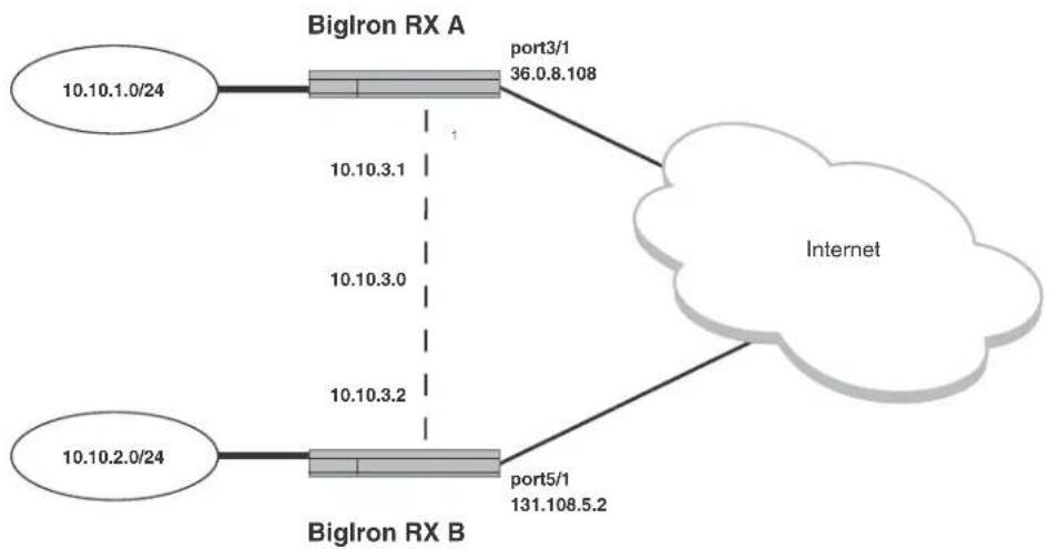
flowchart
graph TD
    A["10.10.1.0/24"] --> B["Port 3/1 36.0.8.108"]
    B --> C["Internet"]
    D["10.10.2.0/24"] --> E["Port5/1 131.108.5.2"]
    E --> C
    B -.->|1| E
    B -.->|10.10.3.1| D
    B -.->|10.10.3.0| D
    D -.->|10.10.3.2| E
Configuration example for BigIron RX A
BigIron RX (config)# interface ethernet 3/1
BigIron RX (config-if-e1000-3/1)# ip address 36.0.8.108/24
BigIron RX (config)# exit
BigIron RX (config)# interface tunnel 1
BigIron RX(config-tnif-1)# tunnel loopback 4/1
BigIron RX(config-tnif-1)# tunnel source 36.0.8.108
BigIron RX(config-tnif-1)# tunnel destination 131.108.5.2
BigIron RX(config-tnif-1)# tunnel mode gre ip
BigIron RX(config-tnif-1)# ip address 10.10.3.1/24
BigIron RX(config-tnif-1)# exit
BigIron RX (config)# ip route 131.108.5.0/24 36.0.8.1
BigIron RX(config)# ip route 10.10.2.0/24 tunnel 1
Configuration example for BigIron RX B
BigIron RX(config)# interface ethernet 5/1
BigIron RX(config-if-e1000-5/1)# ip address 131.108.5.2/24
BigIron RX (config)# exit
BigIron RX (config)# interface tunnel 1
BigIron RX(config-tnif-1)# tunnel loopback 1/1
BigIron RX(config-tnif-1)# tunnel source 131.108.5.2
BigIron RX(config-tnif-1)# tunnel destination 36.0.8.108
BigIron RX(config-tnif-1)# tunnel mode gre ip
BigIron RX(config-tnif-1)# ip address 10.10.3.2/24
BigIron RX(config-tnif-1)# exit
BigIron RX(config)# ip route 36.0.8.0/24 131.108.5.1
BigIron RX(config)# ip route 10.10.1.0/24 tunnel 1
Displaying GRE tunneling information
You can display GRE Tunneling Information using the show ip interface, show ip route and show interface tunnel commands as shown in the following.
| BigIron RX# show ip interface tunnel 1 | ||||||
| Interface | IP-Address | OK? | Method | Status | Protocol | VRF |
| Tunnel 1 | 10.10.3.1 | YES | NVRAM | up | up | default |
Syntax: show ip interface tunnel
This display shows the following information.
TABLE 45 CLI display of interface IP configuration information
| This field... Displays... | |
| Interface The tunnel and tunnel number. | |
| IP-Address | The IP address of the tunnel interface. |
| OK? Whether the IP address has been configured on the tunnel interface. | |
| Method Whether the IP address has been saved in NVRAM. If you have set the IP address for the interface in the CLI, but have not saved the configuration, the entry for the interface in the Method field is “manual”. | |
| Status The link status of the interface. If you have disabled the interface with the disable command, the entry in the Status field will be “administratively down”. Otherwise, the entry in the Status field will be either “up” or “down”. | |
| Protocol Whether the interface can provide two-way communication. If the IP address is configured, and the link status of the interface is up, the entry in the protocol field will be “up”. Otherwise the entry in the protocol field will be “down”. | |
| VRF | The name of the Virtual Routing instance that the tunnel is configured in. |
The show ip route command displays routes that are pointing to a GRE tunnel as shown in the following.
BigIron RX# show ip route
Total number of IP routes: 9
| Type Codes - B:BGP D:Connected I:ISIS S:Static R:RIP O:OSPF; Cost - Dist/Metric | |||||
| Destination | Gateway | Port | Cost | Type | |
| 1 | 2.2.2.1/32 | DIRECT | loopback1 | 0/0 | D |
| 2 | 10.10.1.0/24 | 110.110.2.12 | tunnel 1 | 1/1 | S |
| 3 | 20.2.1.0/24 | DIRECT | eth5/11 | 0/0 | D |
| 4 | 45.4.1.0/24 | 80.8.1.2 | tunnel 2 | 0/0 | D |
| 5 | 63.148.1.0/24 | DIRECT | eth 2/11 | 0/0 | D |
| 6 | 70.7.1.0/24 | DIRECT | eth 2/14 | 0/0 | D |
| 7 | 80.8.1.0/24 | 70.7.1.1 | eth 2/14 | 1/1 | S |
| 8 | 110.110.2.0/24 | 63.148.1.1 | eth 2/11 | 1/1 | S |
| 9 | 189.100.1.0/24 | 110.110.2.12 | tunnel 1 | 0/0 | D |
The show interface tunnel command displays the status and configuration information for a tunnel interface as shown in the following.
BigIron RX# show interface tunnel 1
Tunnel1 is up, line protocol is up
Hardware is Tunnel
Tunnel source 63.148.1.2
Tunnel destination is 110.110.2.12
Tunnel mode gre ip
Tunnel loopback is 1/3
No port name
MTU 1476 Bytes
Syntax: show interface tunnel
The
IPv6 over IPv4 tunnels in hardware
To enable communication between the isolated IPv6 domains using the IPv4 infrastructure, you can configure IPv6 over IPv4 tunnels.
Brocade supports the following IPv6 over IPv4 tunneling in hardware mechanisms:
- Manually configured tunnels
In general, a manually configured tunnel establishes a permanent link between routers in IPv6 domains. A manually configured tunnel has explicitly configured IPv4 addresses for the tunnel source and destination.
This tunneling mechanism requires that the router at each end of the tunnel run both IPv4 and IPv6 protocol stacks. The routers running both protocol stacks, or dual-stack routers, can interoperate directly with both IPv4 and IPv6 end systems and routers.
Configuring a manual IPv6 tunnel
You can use a manually configured tunnel to connect two isolated IPv6 domains. You should deploy this point-to-point tunnel mechanism if you need a permanent and stable connection.
Configuration notes
- The tunnel mode should be ipv6ip indicating that this is ipv6 manual tunnel
- Both source and destination addresses needs to be configured on the tunnel.
- On the remote side we need to have exactly opposite source or destination pair.
- The tunnel destination should be reachable through the ipv4 backbone.
- The ipv6 address on the tunnel needs to be configured for the tunnel to come up
- Both static and dynamic IPv6 routing protocols on top of the tunnel are supported
- The tunnel source can be ip address or interface name
• Manual tunnels provide static point-point connectivity
NOTE
IPV6 over IPV4 tunnel will not work when used with transparent VLAN flooding mode.
FIGURE 8 Manually configured tunne

flowchart
graph LR
    A["IPv6 Network"] --> B["Dual-Stack"]
    B --> C["Tunnel Source"]
    C --> D["IPv4 Network"]
    D --> E["Dual-Stack"]
    E --> F["Tunnel Destination"]
    F --> G["IPv6 Network"]
To configure a manual IPv6 tunnel, enter commands such as the following on a Layer 3 Switch running both IPv4 and IPv6 protocol stacks on each end of the tunnel.
BigIron RX(config)# interface tunnel 1
BigIron RX(config-tnif-1)#tunnel source ethernet 3/1
BigIron RX(config-tnif-1)#tunnel destination 198.162.100.1
BigIron RX(config-tnif-1)#tunnel mode ipv6ip
BigIron RX(config-tnif-1)#ipv6 address 2001:b78:384d:34::/64 eui-64
This example creates tunnel interface 1 and assigns a global IPv6 address with an automatically computed EUI-64 interface ID to it. The IPv4 address assigned to Ethernet interface 3/1 is used as the tunnel source, while the IPv4 address 192.168.100.1 is configured as the tunnel destination. Finally, the tunnel mode is specified as a manual IPv6 tunnel.
Syntax: interface tunnel
For the
Syntax: ipv6 address
You must specify the
You must specify the
Syntax: tunnel source
You must specify the
The ethernet | loopback | ve parameter specifies an interface as the tunnel source. If you specify an Ethernet interface, also specify the port number associated with the interface. If you specify a loopback, VE, or interface, also specify the loopback, VE, or number, respectively.
Syntax: tunnel destination
You must specify the
Syntax: tunnel mode ipv6ip
Clearing IPv6 tunnel statistics
You can clear all IPv6 tunnel statistics (reset all fields to zero) or statistics for a specified tunnel interface.
For example, to clear statistics for tunnel 1, enter the following command at the Privileged EXEC level or any of the Config levels of the CLI.
BigIron RX# clear ipv6 tunnel 1
Syntax: clear ipv6 tunnel
The
Displaying IPv6 tunnel information
To display a summary of tunnel information, enter the following command at any level of the CLI.
BigIron RX# show ipv6 tunnel
IP6 Tunnels
| Tunnel | Mode | Packet Received | Packet Sent |
| 1 | configured | 0 | 0 |
| 2 | configured | 0 | 22419 |
Syntax: show ipv6 tunnel
This display shows the following information.
TABLE 46 IPv6 tunnel information
| This field... Displays... |
| Tunnel The tunnel interface number. |
| Mode The tunnel mode. Possible modes include the following:configured – Indicates a manually configured tunnel.6to4 – Indicates an automatic 6to4 tunnel.auto – Indicates an automatic IPv4-compatible tunnel. |
| Packet Received The number of packets received by a tunnel interface. |
| Packet Sent The number of packets sent by a tunnel interface. |
Displaying tunnel interface information
For example, to display status and configuration information for tunnel interface 1, enter the following command at any level of the CLI.
BigIron RX# show interfaces tunnel 1
Tunnel1 is up, line protocol is up
Hardware is Tunnel
Tunnel source ethernet 3/5
Tunnel destination is not configured
Tunnel mode ipv6ip auto-tunnel
No port name
MTU 1500 bytes
Syntax: show interfaces tunnel
The
This display shows the following information.
TABLE 47 IPv6 tunnel interface information
| This field... Displays... | |
| Tunnel interface status The status of the tunnel interface can be one of the following:up - The tunnel interface is functioning properly.down - The tunnel interface is not functioning and is down. | |
| Line protocol status | The status of the line protocol can be one of the following:up - The line protocol is functioning properly.down - The line protocol is not functioning and is down. |
Hardware is tunnel
The interface is a tunnel interface.
TABLE 47 IPv6 tunnel interface information (Continued)
| This field... Displays... |
| Tunnel source The tunnel source can be one of the following:An IPv4 addressThe IPv4 address associated with an interface or port. |
| Tunnel destination The tunnel destination can an IPv4 address. |
| Tunnel mode The tunnel mode can be one the following:ipv6ip auto-tunnel - Indicates an automatic IPv4-compatible tunnel.ipv6ip 6to4 - Indicates an automatic 6to4 tunnel. |
| Port name The port name configured for the tunnel interface. |
| MTU The setting of the IPv6 maximum transmission unit (MTU). |
Displaying interface level IPv6 settings
To display Interface level IPv6 settings for tunnel interface 1, enter the following command at any level of the CLI.
BigIron RX#show ipv6 inter tunnel 1
Interface Tunnel 1 is up, line protocol is up
    IPv6 is enabled, link-local address is fe80::3:4:2 [Preferred]
    Global unicast address(es):
    1001::1 [Preferred], subnet is 1001::/64
    1011::1 [Preferred], subnet is 1011::/64
Joined group address(es):
    ff02::1:ff04:2
    ff02::5
    ff02::1:ff00:1
    ff02::2
    ff02::1
MTU is 1480 bytes
ICMP redirects are enabled
No Inbound Access List Set
No Outbound Access List Set
OSPF enabled
The display command above reflects the following configuration.
BigIron RX#show running-config interface tunnel 1
!
interface tunnel 1
port-name ManualTunnel1
tunnel mode ipv6ip
tunnel source loopback 1
tunnel destination 2.1.1.1
ipv6 address fe80::3:4:2 link-local
ipv6 address 1011::1/64
ipv6 address 1001::1/64
ipv6 ospf area 0
Configuring Domain Name Server (DNS) resolver
The DNS resolver lets you use a host name to perform Telnet, ping, and traceroute commands. You can also define a DNS domain on a device and thereby recognize all hosts within that domain. After you define a domain name, the device automatically appends the appropriate domain to the host and forwards it to the domain name server.
For example, if the domain “newyork.com” is defined on a device and you want to initiate a ping to host “NYC01” on that domain, you need to reference only the host name in the command instead of the host name and its domain name. For example, you could enter either of the following commands to initiate the ping.
BigIron RX# ping nyc01
BigIron RX# ping nyc01.newyork.com
Defining a DNS entry
You can define up to four DNS servers for each DNS entry. The first entry serves as the primary default address. If a query to the primary address fails to be resolved after three attempts, the next gateway address is queried (also up to three times). This process continues for each defined gateway address until the query is resolved. The order in which the default gateway addresses are polled is the same as the order in which you enter them.
Suppose you want to define the domain name of newyork.com on a device and then define four possible default DNS gateway addresses. To do so, enter the following commands.
BigIron RX(config)# ip dns domain-name newyork.com
BigIron RX(config)# ip dns server-address 209.157.22.199 205.96.7.15 208.95.7.25 201.98.7.15
Syntax: ip dns domain-name
Syntax: ip dns server-address
The first IP address in the ip dns server-address... command becomes the primary gateway address and all others are secondary addresses. Because IP address 201.98.7.15 is the last address listed, it is also the last address consulted to resolve a query.
Defining a domain list
If you want to use more than one domain name to resolve host names, you can create a list of domain names. For example, enter the commands such as the following.
BigIron RX(config)# ip dns domain-list company.com
BigIron RX(config)# ip dns domain-list ds.company.com
BigIron RX(config)# ip dns domain-list hw_company.com
BigIron RX(config)# ip dns domain-list qa_company.com
BigIron RX(config)#
The domain names are tried in the order you enter them.
Syntax: [no] ip dns domain-list
The
The
Use the no form of the command to remove a domain name from the domain-list.
Displaying the domain name list
To determine what domain names have been configured in the domain list, enter the following command.
BigIron RX(config)#show ip dns domain-list
Total number of entries : 3
Primary Domain Name:
Domain Name List:
seq:4 eng.company.co
seq:5 facilities.company.com
seq:12. support.company.com
Syntax: show ip dns domain-list
Verifying domain name or IP address
You can use the ip domain-lookup command to verify the host name for an IP address or the IP address for a host name. For example, if you have an IP address and you want to find out what host name it resolves to, enter the following command.
BigIron RX#ip domain-lookup 66.151.144.5
Host Flag TTL/min Type Address
border2.pc0-0-bbnet1.sje.pnap.net (TMP,OK) 720 IP 66.151.144.5
You can also enter the following.
BigIron RX#ip domain-lookup border2
Host Flag TTL/min Type Address
border2.pc0-0-bbnet1.sje.pnap.net (TMP,OK) 720 IP 66.151.144.5
Syntax: ip domain-loopkup
The complete, qualified host name, along with its IP address and TTL value are displayed.
Adding host names to the DNS cache table
Dynamic cache entries
The entries in a DNS cache table are used to resolve host names to IP addresses. When a client initiates a DNS query, the Brocade device checks the DNS cache table to see if the host name can be resolved to any of the entries. If a match is found, the query is resolved. If a match is not found, the DNS resolver sends the query to the DNS servers. If the name is resolved, the complete, qualified host name and its IP address is added to the DNS cache table and the hosts' IP address is returned to the client.
Static cache entries
You can manually add entries to the DNS cache table if you know a host's complete, qualified name and its IP address. To add host names and their IP addresses to the DNS cache table, enter commands such as the following.
BigIron RX(config)#ip dns cache-entry www.brocade.com 63.236.63.244 720
Syntax: [no] ip dns cache-entry
Use the no form of the command to manually remove an entry from the DNS cache table; however, you must enter the entire entry to delete the entry.
BigIron RX(config)#no ip dns cache-entry www.brocade.com 63.236.63.244
Clearing the DNS cache table
To clear the entire DNS cache table, enter the following command.
BigIron RX#clear ip dns cache-table
To clear a specific entry in DNS cache table, enter the following command.
BigIron RX# clear ip dns cache-table www.brocade.com
OR
BigIron RX# clear ip dns cache-table 63.236.63.244
Syntax: clear ip dns cache-table [ip-address | host-name]
Displaying the DNS cache table
To display what hosts are currently in the DNS cache table, enter the following command.
| BigIron RX(config)#show ip dns cache-table | ||
| Host | Flag | Address |
| border2.pc0-0-bbnet1.sje.pnap.net | (TMP,OK) | 66.151.144.5 |
| sl-internap-109-0.sprintlink.net | (TMP,OK) | 144.223.242.86 |
| sl-st21-sj-13-0.sprintlink.net | (TMP,OK) | 144.232.20.59 |
| mail.company.com | (STA,OK) | 64.236.22.148 |
To display the individual entries in the cache-table, enter a command such as the following.
BigIron RX(config)#show ip dns cache-table border2 Host Flag TTL/min Address border2.pc0-0-bbnet1.sje.pnap.net (TMP,OK) 720 66.151.144.5
OR
BigIron RX(config)#show ip dns cache-table 66.151.144.5 Host Flag TTL/min Address border2.pc0-0-bbnet1.sje.pnap.net (TMP,OK) 720 66.151.144.5
TABLE 48 The show ip dns cache-table output
| This field... Displays... | |
| Host The complete, qualified domain name of the host. | |
| Flag Indicates if the entry is dynamic or static and if the information for the domain is up to date:TMP – Entry is dynamicSTA – Entry is staticOK – Information for the entry is up to dateEX – The entry is expired and would not be used. Such an entry would be deleted from the cache table at next cache poll refresh. | |
| TTL/min If the entry is dynamic (TMP) this value shows how long the entry remains in the DNS cache table. If the entry is static (STA), it remains in the DNS cache table and never changes until it is manually removed or the DNS cache table is cleared. | |
| Address The IP address of the entry. |
Syntax: show ip dns cache-table [host-name | ip-address]
Defining the polling interval
The polling interval determines how often the Brocade device checks the status of the entries in the DNS cache table to determine if the information for that host has changed. If the TTL value of the cache entry is expired the entry is removed from the cache-table.
To define a polling interval, enter the following command.
BigIron RX(config)#ip dns poll-interval 7
Syntax: ip dns poll-interval
Enter the polling interval in minutes. The default is 1 minute.
Displaying the polling interval
To display the current polling interval configured for the device, enter the following command.
BigIron RX(config)#show ip dns poll-time-interval Current DNS polling interval is 7 minutes
Syntax: show ip dns poll-time-interval
Displaying the server list
To display the current DNS server list configured for the device, enter the following command.
BigIron RX#show ip dns server-list Total number of DNS Servers configured: 2 Server List: 10.51.17.30 10.51.17.29
Syntax: show ip dns server-list
Debugging the DNS feature
To debug the DNS feature enter the following command.
BigIron RX#debug ip dns
IP: dns debugging is on
Syntax: debug ip dns
Using a DNS name to initiate a trace route
Suppose you want to trace the route from a device to a remote server identified as NYC02 on domain newyork.com.
FIGURE 9 Querying a host on the newyork.com domain
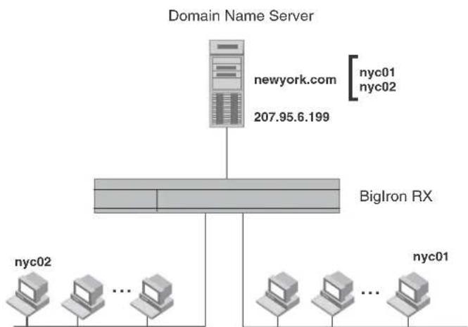
flowchart
graph TD
    A["Domain Name Server"] --> B["newyork.com"]
    B --> C["207.95.6.199"]
    C --> D["BigIron RX"]
    D --> E["nyc02"]
    D --> F["..."]
    D --> G["nyc01"]
    E --> H["nyc02"]
    F --> I["..."]
    G --> J["nyc01"]
Because the newyork.com domain is already defined on the device, you need to enter only the host name, NYC02, as noted below.
BigIron RX# traceroute nyc02
Syntax: traceroute
The only required parameter is the IP address of the host at the other end of the route.
After you enter the command, a message indicating that the DNS query is in process and the current gateway address (IP address of the domain name server) being queried appear on the screen.
Type Control-c to abort
Sending DNS Query to 209.157.22.199
Tracing Route to IP node 209.157.22.80
To ABORT Trace Route, Please use stop-traceroute command.
Traced route to target IP node 209.157.22.80:
IP Address
Round Trip Time1
Round Trip Time2
207.95.6.30
93 msec
121 msec
NOTE
In the above example, 209.157.22.199 is the IP address of the domain name server (default DNS gateway address), and 209.157.22.80 represents the IP address of the NYC02 host.
Configuring packet parameters
You can configure the following packet parameters to control how the device sends IP packets to other devices on an Ethernet network. The device always places IP packets into Ethernet packets to forward them on an Ethernet port:
- Encapsulation type – The format for the Layer 2 packets within which the device sends IP packets.
- Maximum Frame Size – The maximum frame size that applies to all ports on a packet processor (PPCR).
- IP Maximum Transmission Unit (MTU) – The maximum length of IP packet that a Layer 2 packet can contain. IP packets that are longer than the IP MTU are fragmented and sent in multiple Layer 2 packets. You can change the IP MTU globally or on a port.
- Global IP MTU – The default IP MTU value depends on the encapsulation type on a port and is 1500 bytes for Ethernet II encapsulation and 1492 bytes for SNAP encapsulation.
- Port IP MTU – A port's default IP MTU depends on the encapsulation type enabled on the port.
Changing the encapsulation type
The device encapsulates IP packets into Layer 2 packets, to send the IP packets on the network. A Layer 2 packet is also called a MAC layer packet or an Ethernet frame. The MAC address of the device interface sending the packet is the source address of the Layer 2 packet. The Layer 2 packet's destination address can be one of the following:
- The MAC address of the IP packet's destination. In this case, the destination device is directly connected to the device.
- The MAC address of the next-hop gateway toward the packet's destination.
- An Ethernet broadcast address.
The entire IP packet, including the source address, destination address, other control information, and the data, is placed in the data portion of the Layer 2 packet. Typically, an Ethernet network uses one of two different formats of Layer 2 packet:
- Ethernet II
- Ethernet SNAP (also called IEEE 802.3)
The control portions of these packets differ slightly. All IP devices on an Ethernet network must use the same format. The device uses Ethernet II by default. You can change the IP encapsulation to Ethernet SNAP on individual ports if needed.
NOTE
All devices connected to the device port must use the same encapsulation type.
To change the IP encapsulation type on interface 1/5 to Ethernet SNAP, enter the following commands.
BigIron RX(config)# int e 1/5
BigIron RX(config-if-e1000-1/5)# ip encapsulation snap
Syntax: ip encapsulation snap | ethernet-2
Setting maximum frame size per PPCR
You can set a maximum frame size of IP packets that are forwarded on all ports of a PPCR. You can set a maximum frame size globally and per interface.
Globally setting the maximum frame size (jumbo frame)
To set a maximum frame size (otherwise referred to as jumbo frame) that applies to the device, enter a command such as the following.
BigIron RX(config)# default-max-frame-size 2000
BigIron RX(config)# write memory
BigIron RX(config)# reload
Syntax: default-max-frame-size
Enter 64 - 9212 for
Setting a maximum frame size per interface
When you set a maximum frame size on an interface, that size applies to all ports in a PPCR. Table 49 shows the ports of each Interface module.
TABLE 49 Available ports per PPCR
| Module type Number of packet processors (PPCR) | Ports in a PPCR |
| PPCR1 PPCR2 PPCR3 PPCR4 | |
| 24 x 1G 2 1 - 12 13 - 24 N/A | N/A |
To set a maximum frame size for all the ports attached to a PPCR, enter a command such as the following at the Interface Configuration level.
BigIron RX(config)#interface ethernet 6/4
BigIron RX(config-if-e1000-6/4)#max-frame-size 1500 bytes
BigIron RX(config-if-e1000-6/4)#write memory
BigIron RX(config-if-e1000-6/4)#exit
BigIron RX(config)#reload
In this example the maximum frame size is applied to port 4 of a 24 x 1G Ethernet Interface module. That means that this maximum will apply to ports 1 to 10 on the interface module.
To configure the untagged max-frame-size on a VLAN, enter a command such as the following at the Interface Configuration level.
BigIron RX(config-vlan-20)#
BigIron RX(config-vlan-20)#max-frame-size 5000
Please reload system!
BigIron RX(config-vlan-20)#
Syntax: max-frame-size
The
Changing the MTU
The IP MTU is the maximum length of an IP packet that a Layer 2 packet can contain. If an IP packet is larger than the IP MTU allowed by the Layer 2 packet, the device fragments the IP packet into multiple parts that will fit into Layer 2 packets, and sends the parts of the fragmented IP packet separately, in different Layer 2 packets. The device that receives the multiple fragments of the IP packet reassembles the fragments into the original packet.
The default IP MTU is 1500 bytes for Ethernet II packets and 1492 for Ethernet SNAP packets. You can change the IP MTU globally or an individual ports. You can increase the IP MTU size to accommodate large packet sizes, such as jumbo packets, globally or on individual physical ports. However, IP MTU cannot be set higher than the maximum frame size, minus 18.
For jumbo packet, the device supports hardware forwarding of Layer 3 jumbo packets. Layer 3 IP unicast jumbo packets received on a port that supports the frame's IP MTU size and forwarded to another port that also supports the frame's IP MTU size are forwarded in hardware.
Configuration considerations for Increasing the IP MTU
Consider the following before configuring the maximum value to increase the IP MTU:
- The maximum value of an IP MTU cannot exceed the configured maximum frame size (jumbo frame), minus 18. For example, global IP MTU cannot exceed the value of default-max-frame-size, minus 18 bytes. IP MTU for an interface cannot exceed the value of the maximum frame size configured on a port, minus 18 bytes. The 18 bytes is used for IP overhead, VLAN tagging, etc.
- When you increase the IP MTU size of a port, the increase uses system resources. Increase the IP MTU size only on the ports that need it. For example, if you have one port connected to a server that uses jumbo frames and two other ports connected to clients that can support the jumbo frames, increase the IP MTU only on those three ports. Leave the IP MTU size on the other ports at the default value (1500 bytes). Globally increase the IP MTU size only if needed.
- Use the same IP MTU size on all ports that will be supporting jumbo frames. If the device needs to fragment a jumbo frame (and the frame does not have the DF bit set), the device fragments the frame into 1500-byte fragments, even if the outbound port has a larger IP MTU. For example, if a port has an IP MTU setting of 8000 and receives an 8000-byte frame, then must forward the frame onto a port with an IP MTU of 4000, the device does not fragment the 8000-byte frame into two 4000-byte frames. Instead, the device fragments the 8000-byte frame into six fragments (five 1500-byte fragments and a final, smaller fragment.)
Globally changing the IP MTU
To globally enable jumbo support on all ports, enter commands such as the following.
BigIron RX(config)# ip mtu 5000
BigIron RX(config)# write memory
Syntax: [no] ip mtu
The
NOTE
The BigIron RX will always use 22 Bytes less than the configured MTU in order to compensate for the 4Bytes required for VLAN tags. This is so if a packet is forwarded on both a tagged and untagged link within a VLAN, it will get through.
Changing the maximum transmission unit on an individual interface
By default, the maximum IP MTU sizes are as follows:
- 1500 bytes – The maximum for Ethernet II encapsulation
• 1492 bytes – The maximum for SNAP encapsulation
NOTE
The IP MTU configured at the physical interface level takes precedence over the IP MTU configured at the global level for that physical interface.
To change the IP MTU for interface 1/5 to 1000, enter the following commands.
BigIron RX(config)# int e 1/5 BigIron RX(config-if-e10000-5)# ip mtu 1000
Syntax: [no] ip mtu
The
Changing the router ID
In most configurations, a device has multiple IP addresses, usually configured on different interfaces. As a result, a device's identity to other devices varies depending on the interface to which the other device is attached. Some routing protocols, including OSPF and BGP4, identify a device by just one of the IP addresses configured on the device, regardless of the interfaces that connect the devices. This IP address is the router ID.
NOTE
RIP does not use the router ID.
NOTE
If you change the router ID, all current BGP4 sessions are cleared.
By default, the router ID on a device is one of the following:
- If the router has loopback interfaces, the default router ID is the IP address configured on the lowest numbered loopback interface configured on the device. For example, if you configure loopback interfaces 1, 2, and 3 as follows, the default router ID is 9.9.9.9/24:
- Loopback interface 1, 9.9.9.9/24
- Loopback interface 2, 4.4.4.4/24
- Loopback interface 3, 1.1.1.1/24
- If the device does not have any loopback interfaces, the default router ID is the lowest numbered IP interface configured on the device.
If you prefer, you can explicitly set the router ID to any valid IP address. The IP address cannot be in use on another device in the network.
NOTE
The device uses the same router ID for both OSPF and BGP4. If the router is already configured for OSPF, you may want to use the router ID that is already in use on the router rather than set a new one. To display the router ID, enter the show ip CLI command at any CLI level.
To change the router ID, enter a command such as the following.
BigIron RX(config)# ip router-id 209.157.22.26
Syntax: ip router-id
The
NOTE
You can specify an IP address used for an interface, but do not specify an IP address in use by another device.
Specifying a single source interface for Telnet, TACACS, TACACS+, or RADIUS packets
When the device originates a Telnet, TACACS, TACACS+, or RADIUS packet, the source address of the packet is the lowest-numbered IP address on the interface that sends the packet. You can configure the device to always use the lowest-numbered IP address on a specific interface as the source addresses for these types of packets. When you configure the device to use a single source interface for all Telnet, TACACS, TACACS+, or RADIUS packets, the device uses the same IP address as the source for all packets of the specified type, regardless of the ports that actually sends the packets.
Identifying a single source IP address for Telnet, TACACS, TACACS+, or RADIUS packets provides the following benefits:
- If your Telnet, TACACS, TACACS+, or RADIUS server is configured to accept packets only from specific IP addresses, you can use this feature to simplify configuration of the server by configuring the Brocade device to always send the packets from the same link or source address.
- If you specify a loopback interface as the single source for Telnet, TACACS, TACACS+, or RADIUS packets, servers can receive the packets regardless of the states of individual links. Thus, if a link to the server becomes unavailable but the client or server can be reached through another link, the client or server still receives the packets, and the packets still have the source IP address of the loopback interface.
The software contains separate CLI commands for specifying the source interface for Telnet, TACACS, TACACS+, or RADIUS packets. You can configure a source interface for one or more of these types of packets separately.
To specify an Ethernet or a loopback or virtual interface as the source for all TACACS and TACACS+ packets from the device, use the following CLI method. The software uses the lowest-numbered IP address configured on the port or interface as the source IP address for TACACS, TACACS+ packets originated by the device.
The following sections show the syntax for specifying a single source IP address for Telnet, TACACS, TACACS+, and RADIUS packets.
Telnet packets
To specify the lowest-numbered IP address configured on a virtual interface as the device's source for all Telnet packets, enter commands such as the following.
BigIron RX(config)# int loopback 2
BigIron RX(config-lbif-2)# ip address 10.0.0.2/24
BigIron RX(config-lbif-2)# exit
BigIron RX(config)# ip telnet source-interface loopback 2
The commands configure loopback interface 2, assign IP address 10.0.0.2/24 to the interface, then designate the interface as the source for all Telnet packets from the device.
Syntax: ip telnet source-interface ethernet
The
The following commands configure an IP interface on an Ethernet port and designate the address port as the source for all Telnet packets from the device.
BigIron RX(config)# interface ethernet 1/4
BigIron RX(config-if-e10000-1/4)# ip address 209.157.22.110/24
BigIron RX(config-if-e10000-1/4)# exit
BigIron RX(config)# ip telnet source-interface ethernet 1/4
TACACS and TACACS+ packets
To specify the lowest-numbered IP address configured on a virtual interface as the device's source for all TACACS and TACACS+ packets, enter commands such as the following.
BigIron RX(config)# int ve 1
BigIron RX(config-vif-1)# ip address 10.0.0.3/24
BigIron RX(config-vif-1)# exit
BigIron RX(config)# ip tacacs source-interface ve 1
The commands configure virtual interface 1, assign IP address 10.0.0.3/24 to the interface, then designate the interface as the source for all TACACS and TACACS+ packets from the device.
Syntax: ip tacacs source-interface ethernet
The
RADIUS packets
To specify the lowest-numbered IP address configured on a virtual interface as the device's source for all RADIUS packets, enter commands such as the following.
BigIron RX(config)# int ve 1
BigIron RX(config-vif-1)# ip address 10.0.0.3/24
BigIron RX(config-vif-1)# exit
BigIron RX(config)# ip radius source-interface ve 1
The commands configure virtual interface 1, assign IP address 10.0.0.3/24 to the interface, then designate the interface as the source for all RADIUS packets from the device.
Syntax: ip radius source-interface ethernet
The
Configuring an interface as the source for Syslog packets
You can configure the device to use the lowest-numbered IPv4 or IPv6 address configured on a loopback interface, virtual interface, or Ethernet port as the source for all Syslog packets from the device. The software uses the lowest-numbered IP or IPv6 address configured on the interface as the source IP address for the packets.
For example, to specify the lowest-numbered IP address configured on a virtual interface as the device's source for all Syslog packets, enter commands such as the following:.
BigIron RX(config)# int ve 1
BigIron RX(config-vif-1)# ip address 10.0.0.4/24
BigIron RX(config-vif-1)# exit
BigIron RX(config)# ip syslog source-interface ve 1
The commands in this example configure virtual interface 1, assign IP address 10.0.0.4/24 to the interface, then designate the interface's address as the source address for all Syslog packets.
Syntax: [no] ip syslog source-interface ethernet [
The
The default is the lowest-numbered IP or IPv6 address configured on the port through which the packet is sent. The address therefore changes, by default, depending on the port.
IP fragmentation protection
Beginning with this release, IP packet filters on the device switches will drop undersized fragments and overlapping packet fragments to prevent tiny fragment attacks as explained in RFC 1858.
When packets are fragmented on the network, the first fragment of a packet must be large enough to contain all the necessary header information. Fragments, once reassembled, must meet certain criteria before they are allowed to pass through the network. There are no CLI commands for this new security feature.
IP option attack protection
An attack on the network could be accomplished using the options field of an IP packet header. For example, the source routing option makes it possible for the sender to specify a route to follow.
To protect against attacks contained in the option field, devices drop any IP packet that contains an option in its header, except for packets. IGMP packets are processes even if they contain IP options. If you want other packets that contain options in their headers to be processed, enter a command such as the following.
BigIron RX(config)#ip ip-option-process
Syntax: [no] ip ip-option-process
IP receive access list
The IP receive access list feature uses IPv4 ACLs to filter the packets intended for the management process to protect the management module from being overloaded with heavy traffic that was sent to one of the Layer 3 Switch IP interfaces. The feature applies to IPv4 unicast and multicast packets.
Configuring IP receive access list
IP receive access list is a global configuration command. Once it is applied, the command will be effective on all the management modules on the device. To configure the feature, do the following.
- Create a numbered ACL that will be used as the IP receive ACL. This ACL can be a standard (1-99) or extended (100-199) ACL. Named ACLs are not supported.
BigIron RX(config)# access-list 10 deny host 209.157.22.26 log
BigIron RX(config)# access-list 10 deny 209.157.29.12 log
BigIron RX(config)# access-list 10 deny host IPHost1 log
BigIron RX(config)# access-list 10 permit any
BigIron RX(config)# write memory
- Configure ACL 10 as the IP receive access list by entering the following command.
BigIron RX(config)# ip receive access-list 10
Syntax: [no] ip receive access-list
Specify an access list number for
The IP receive ACL is applied globally to all interfaces on the device.
Displaying IP receive access list
To determine if IP receive access list has been configured on the device, enter the following command.
BigIron RX# show access-list bindings L4 configuration:
ip receive access-list 101
Configuring ARP parameters
Address Resolution Protocol (ARP) is a standard IP protocol that enables the device to obtain the MAC address of another device's interface when the device knows the IP address of the interface. ARP is enabled by default and cannot be disabled.
How ARP works
The device needs to know a destination's MAC address when forwarding traffic, because the device encapsulates the IP packet in a Layer 2 packet (MAC layer packet) and sends the Layer 2 packet to a MAC interface on a device directly attached to the device. The device can be the packet's final destination or the next-hop router toward the destination.
The device encapsulates IP packets in Layer 2 packets regardless of whether the ultimate destination is locally attached or is multiple router hops away. Since the device's IP route table and IP forwarding cache contain IP address information but not MAC address information, the device cannot forward IP packets based solely on the information in the route table or forwarding cache. The device needs to know the MAC address that corresponds with the IP address of either the packet's locally attached destination or the next-hop router that leads to the destination.
For example, to forward a packet whose destination is multiple router hops away, the device must send the packet to the next-hop router toward its destination, or to a default route or default network route if the IP route table does not contain a route to the packet's destination. In each case, the device must encapsulate the packet and address it to the MAC address of a locally attached device, the next-hop router toward the IP packet's destination.
To obtain the MAC address required for forwarding a datagram, the device does the following:
- First, the device looks in the ARP cache (not the static ARP table) for an entry that lists the MAC address for the IP address. The ARP cache maps IP addresses to MAC addresses. The cache also lists the port attached to the device and, if the entry is dynamic, the age of the entry. A dynamic ARP entry enters the cache when the device receives an ARP reply or receives an ARP request (which contains the sender's IP address and MAC address). A static entry enters the ARP cache from the static ARP table (which is a separate table) when the interface for the entry comes up.
To ensure the accuracy of the ARP cache, each dynamic entry has its own age timer. The timer is reset to zero each time the device receives an ARP reply or ARP request containing the IP address and MAC address of the entry. If a dynamic entry reaches its maximum allowable age, the entry times out and the software removes the entry from the table. Static entries do not age out and can be removed only by you.
- If the ARP cache does not contain an entry for the destination IP address, the device broadcasts an ARP request out all its IP interfaces. The ARP request contains the IP address of the destination. If the device with the IP address is directly attached to the device, the device sends an ARP response containing its MAC address. The response is a unicast packet addressed directly to the device. The device places the information from the ARP response into the ARP cache.
ARP requests contain the IP address and MAC address of the sender, so all devices that receive the request learn the MAC address and IP address of the sender and can update their own ARP caches accordingly.
NOTE
The ARP request broadcast is a MAC broadcast, which means the broadcast goes only to devices that are directly attached to the device. A MAC broadcast is not routed to other networks. However, some routers, including the device, can be configured to reply to ARP requests from one network on behalf of devices on another network. Refer to “Enabling proxy ARP” on page 190.
NOTE
If the router receives an ARP request packet that it is unable to deliver to the final destination because of the ARP timeout and no ARP response is received (the device knows of no route to the destination address), the router sends an ICMP Host Unreachable message to the source.
Rate limiting ARP packets
You can limit the number of ARP packets the device accepts during each second. By default, the software does not limit the number of ARP packets the device can receive. Since the device sends ARP packets to the CPU for processing, if a device in a busy network receives a high number of ARP packets in a short period of time, some CPU processing might be deferred while the CPU processes the ARP packets.
To prevent the CPU from becoming flooded by ARP packets in a busy network, you can restrict the number of ARP packets the device will accept each second. When you configure an ARP rate limit, the device accepts up to the maximum number of packets you specify, but drops additional ARP packets received during the one-second interval. When a new one-second interval starts, the counter restarts at zero, so the device again accepts up to the maximum number of ARP packets you specified, but drops additional packets received within the interval.
To limit the number of ARP packets the device will accept each second, enter a command such as the following at the global CONFIG level of the CLI.
BigIron RX(config)# arp-port-rate-limit 100
This command configures the device to accept up to 100 ARP packets each second. If the device receives more than 100 ARP packets during a one-second interval, the device drops the additional ARP packets during the remainder of that one-second interval.
Syntax: [no] arp-port-rate-limit
The
Applying a rate limit to ARP packets on an interface
To prevent the CPU from becoming flooded by ARP packets in a busy network, you can restrict the number of ARP packets an interface will accept each second. When ARP rate limit is configured on an interface, the interface will accept up to the maximum number of packets you specify, but drops additional ARP packets received during the one-second interval. When a new one-second interval starts, the counter restarts at zero, so the interface again accepts up to the maximum number of ARP packets you specified, but drops additional packets received within the interval. This feature is disabled by default.
Configuration notes
- When configuring ARP rate limiting globally, interfcae level ARP rate-limiting gets removed.
- The interface level configuration overrides the global configuration for a specific port.
- The command is supported on Layer 3 Switches only.
- There is no default value for
. Enter 0–30,000. - If the value of
is entered as 0, the interface will stop processing ARP packets immediately. - You can go to interface trunk mode to configure the ARP port rate limit. When configured over trunk interface (i.e. on the lead port) the same limit will be configured on each and every port in the trunk.
- ARP rate limiting is only supported on physical interfaces (virtual interfaces (ve) are not supported).
Setting the rate limit to ARP packets on an interface
You can limit the number of ARP packets the device will accept each second by entering the arp-port-rate-limit command. However, if you want to apply a limit on the rate that ARP packets flow on an interface of a Layer 3 Switch, enter a command such as the following.
BigIron RX(config)#interface ethernet 1/4
BigIron RX(config-vif-10)#arp-port-rate-limit 2000
Syntax: [no] arp-port-rate-limit
There is no default value for
Displaying the rate limit for ARP packets
To determine how many ARP packets were dropped by an interface due to the configured rate limit for ARP packets, enter a command such as the following.
LP-1#show ip traffic arp
ARP Statistics
1400 total recv, 1400 req recv, 0 req sent
0 pending drop, 0 invalid source, 0 invalid dest
| ARP Rate Limiting Statistics | |||
| Interface | Received | Processed | Dropped (Rate-limited) |
| ethernet1/1 | 184200 | 700 | 183500 |
| ethernet1/2 | 0 | 0 | 0 |
| ethernet1/3 | 0 | 0 | 0 |
| ethernet1/4 | 184200 | 700 | 183500 |
The example above displays the LP processed 50 packets every second and dropped any additional packets.
Syntax: show ip traffic arp
This column... Displays...
| Interface The interface on the device. |
| Received Number of ARP packets received by the interface. |
| Processed Number of ARP packets processed by the interface. |
| Dropped (Rate-limited) Number of ARP packets dropped by the interface. |
Clearing the rate limit for ARP packets
To clear the ARP port rate limit data on every port of the LP, enter a command such as the following.
LP-1# clear ip traffic arp
Changing the ARP aging period
When the device places an entry in the ARP cache, the device also starts an aging timer for the entry. The aging timer ensures that the ARP cache does not retain learned entries that are no longer valid. An entry can become invalid when the device with the MAC address of the entry is no longer on the network.
The ARP age affects dynamic (learned) entries only, not static entries. The default ARP age is ten minutes. On the device, you can change the ARP age to a value from 0 – 240 minutes. If you set the ARP age to zero, aging is disabled and entries do not age out.
To globally change the ARP aging parameter to 20 minutes, enter the following command.
BigIron RX(config)# ip arp-age 20
Syntax: ip arp-age
The
To override the globally configured IP ARP age on an individual interface, enter a command such as the following at the interface configuration level.
BigIron RX(config-if-e1000-1/1)# ip arp-age 30
Enabling proxy ARP
Proxy ARP allows the device to answer ARP requests from devices on one network on behalf of devices in another network. Since ARP requests are MAC-layer broadcasts, they reach only the devices that are directly connected to the sender of the ARP request. Thus, ARP requests do not cross routers.
For example, if Proxy ARP is enabled on the device connected to two subnets, 10.10.10.0/24 and 20.20.20.0/24, the device can respond to an ARP request from 10.10.10.69 for the MAC address of the device with IP address 20.20.20.69. In standard ARP, a request from a device in the 10.10.10.0/24 subnet cannot reach a device in the 20.20.20.0 subnet if the subnets are on different network cables, and thus is not answered.
NOTE
An ARP request from one subnet can reach another subnet when both subnets are on the same physical segment (Ethernet cable), since MAC-layer broadcasts reach all the devices on the segment.
Proxy ARP is disabled by default.
To enable IP proxy ARP, enter the following command.
BigIron RX(config)# ip proxy-arp
To again disable IP proxy ARP, enter the following command.
BigIron RX(config)# no ip proxy-arp
Syntax: [no] ip proxy-arp
Creating static ARP entries
The device has a static ARP table, in addition to the regular ARP cache. The static ARP table contains entries that you configure.
Static entries are useful in cases where you want to pre-configure an entry for a device that is not connected to the device, or you want to prevent a particular entry from aging out. The software removes a dynamic entry from the ARP cache if the ARP aging interval expires before the entry is refreshed. Static entries do not age out, regardless of whether the Brocade device receives an ARP request from the device that has the entry's address.
You can increase the number of configurable static ARP entries. Refer to “Changing the maximum number of entries the static ARP table can hold” on page 191.
To display the ARP cache and static ARP table, see the following:
- To display the ARP table, refer to "Displaying the ARP cache" on page 224.
- To display the static ARP table, refer to "Displaying the static ARP table" on page 226.
To create a static ARP entry for a static MAC entry, enter a command such as the following.
BigIron RX(config)# arp 1 192.53.4.2 1245.7654.2348 e 1/2
The command adds a static ARP entry that maps IP address 192.53.4.2 to MAC address 1245.7654.2348. The entry is for a MAC address connected to port 1/2 of the device.
Syntax: arp
The
The
The ethernet
The arp command allows you to specify only one port number. To create a static ARP entry for a static MAC entry that is associated with multiple ports, specify the first (lowest-numbered) port associated with the static MAC entry.
Changing the maximum number of entries the static ARP table can hold
The default number of entries in the static ARP table on the device are as follows:
- Default maximum: 8192
- Configurable maximum: 65536
NOTE
You must save the configuration to the startup configuration file and reload the software after changing the static ARP table size to place the change into effect.
NOTE
The basic procedure for changing the static ARP table size is the same as the procedure for changing other configurable cache or table sizes. Refer to “Displaying and modifying system parameter default settings” on page 130.
To increase the maximum number of entries in the static ARP table you can configure, enter commands such as the following at the global CONFIG level of the CLI.
BigIron RX(config)# system-max ip-static-arp 4000
BigIron RX(config)# write memory
BigIron RX(config)# end
BigIron RX# reload
Syntax: system-max ip-static-arp
The
The maximum number of static ARP entries is 16384 (default: 2048).
NOTE
As of release 2.4.00, the system-max static-arp command no longer affects memory allocation for static ARPs. Instead, the BigIron RX dynamically allocates memory for static-arp entries as required and this is only limited by the memory allocation for all ARP entries, specified by the system-max ip-arp command.
Creating a floating static ARP entry
You can create a static ARP entry without port assignments.
When a floating static ARP entry (Static ARP entry without the outgoing interface defined) is added to the ARP Inspection table, the mapping is checked against the current static ARP table. If an ARP entry with a matching IP but mismatch MAC is found, it will be deleted and a re-arp on the IP will be issued.
When an ARP entry is deleted from ARP Inspection table, the corresponding entry in the static ARP table will also be deleted.
To create a floating static ARP entry for a static MAC entry, enter a command such as the following.
BigIron RX(config)# arp 192.53.4.2 1245.7654.2348
The command adds a floating static ARP entry that maps IP address 192.53.4.2 to MAC address 1245.7654.2348.
Syntax: arp <ip-add> <mac-addr>
The
The
Static route ARP validation check
You can configure the BigIron RX to perform validation checks on the destination MAC address, the sender and target IP addresses, and the source MAC address.
You can enable ARP validation check on the global basis. When feature is enabled, the static route will only be installed when the next hop ARP has been resolved.
Configuring an ARP validation check
To enable the ARP validation check globally, enter a command such as the following.
BigIron RX(config)#ip route validate-nexthop-arp
Syntax: [no] ip route validate-nexthop-arp
Use the no form of the command to disable the ARP validation feature. When ARP validation is disabled, the static route will be installed without checking the validity of the next hop.
Enabling the next hop validate ARP timer
The next hop validate ARP timer works only on the ARP entries created when the ARP validation check feature has been enabled. The timer is used to age out the ARP entries when the next hop goes down. All other ARP entries in the system, which are NOT created due to static routes, follow the normal ARP age timer with default value of 3 minutes.
Use the ARP validation timer to reduce the response time where the static route with the next hop down can be replaced quickly with a route with active next hop.
To set the ARP validation timer to 30 seconds, enter commnads such as the following.
BigIron RX(config)#ip route validate-nexthop-arp
BigIron RX(config)#ip route validate-nexthop-arp timer 30
Syntax: [no] ip route validate-nexthop-arp timer
The default is 200 seconds.
The value parameter specifies the amount of time before a nexthop down is replaced by an active nexthop. Possible values are 10-200 seconds.
Use the no form of the command to disable the validation timer.
Displaying the routes waiting for the next hop ARP to resolve
Use the following command to display which routes are waiting for the nexthop ARP to be resolved.
BigIron RX# show ip static route
IP Static Routing Table - 2 entries:
Type Codes: '*' - Installed, '+' - Waiting for ARP resolution
IP Prefix Next Hop Interface Dis/Metric/Tag
*10.0.0.0/8 10.43.14.1 1/1/0
+20.1.1.0/24 12.1.1.2 1/1/0
*20.1.1.0/24 12.1.1.6 1/1/0
+20.1.1.0/24 12.1.1.7 5/1/0
20.1.1.0/24 10.43.14.1 10/1/0
Displaying ARP
When the next hop entry is a static route, enter the following command to display the route and the timer value.
BigIron RX# show arp 10.43.14.1
Total number of ARP entries: 1
IP Address MAC Address Type Age Port Status
1 10.43.14.1 00ab.cdef.0100 Dynamic 5 mgmt1 Valid
ARP Debug Info
ArpIndex 0 InstId 16840 OutInt 2048 Vlan:0
HwMacIndex 0x0000ffff Router 0 PktCount 0
NumReq 0 ReplyTimeout 100
For additional information on the command syntax, refer to the syntax of the show arp command under “Displaying the ARP cache” on page 224.
Configuring forwarding parameters
The following configurable parameters control the forwarding behavior of the device:
• Time-To-Live (TTL) threshold
• Forwarding of directed broadcasts
- Forwarding of source-routed packets
- Ones-based and zero-based broadcasts
All these parameters are global and thus affect all IP interfaces configured on the device.
To configure these parameters, use the procedures in the following sections.
Changing the TTL threshold
The TTL threshold prevents routing loops by specifying the maximum number of router hops an IP packet originated by the device can travel through. Each device capable of forwarding IP that receives the packet decreases the packet's TTL by one. If a device receives a packet with a TTL of 1 and reduces the TTL to zero, the device drops the packet.
The default TTL is 64. You can change the TTL to a value from 1-255.
To modify the TTL threshold to 25, enter the following commands.
BigIron RX(config)# ip ttl 25
Syntax: ip ttl <1-255>
Enabling forwarding of directed broadcasts
A directed broadcast is an IP broadcast to all devices within a single directly-attached network or subnet. A net-directed broadcast goes to all devices on a given network. A subnet-directed broadcast goes to all devices within a given subnet.
NOTE
A less common type, the all-subnets broadcast, goes to all directly-attached subnets. Forwarding for this broadcast type also is supported, but most networks use IP multicasting instead of all-subnet broadcasting.
Forwarding for all types of IP directed broadcasts is disabled by default. You can enable forwarding for all types if needed. You cannot enable forwarding for specific broadcast types.
To enable forwarding of IP directed broadcasts, enter the following command.
BigIron RX(config)# ip directed-broadcast
Syntax: [no] ip directed-broadcast
Brocade software makes the forwarding decision based on the router's knowledge of the destination network prefix. Routers cannot determine that a message is unicast or directed broadcast apart from the destination network prefix. The decision to forward or not forward the message is by definition only possible in the last hop router.
To disable the directed broadcasts, enter the following command in the CONFIG mode.
BigIron RX(config)# no ip directed-broadcast
To enable directed broadcasts on an individual interface instead of globally for all interfaces, enter commands such as the following.
BigIron RX(config)# interface ethernet 1/1 BigIron RX(config-if-e10000-1/1)# ip directed-broadcast
Syntax: [no] ip directed-broadcast
Disabling forwarding of IP source-routed packets
A source-routed packet specifies the exact router path for the packet. The packet specifies the path by listing the IP addresses of the router interfaces through which the packet must pass on its way to the destination. The device supports both types of IP source routing:
- Strict source routing – requires the packet to pass through only the listed routers. If the device receives a strict source-routed packet but cannot reach the next hop interface specified by the packet, the device discards the packet and sends an ICMP Source-Route-Failure message to the sender.
NOTE The device allows you to disable sending of the Source-Route-Failure messages. Refer to "Disabling ICMP messages" on page 196.
- Loose source routing – requires that the packet pass through all of the listed routers but also allows the packet to travel through other routers, which are not listed in the packet.
The device forwards both types of source-routed packets by default. You cannot enable or disable strict or loose source routing separately.
To disable forwarding of IP source-routed packets, enter the following command.
BigIron RX(config)# no ip source-route
Syntax: [no] ip source-route
To re-enable forwarding of source-routed packets, enter the following command.
BigIron RX(config)# ip source-route
Enabling support for zero-based IP subnet broadcasts
By default, the device treats IP packets with all ones in the host portion of the address as IP broadcast packets. For example, the device treats IP packets with 209.157.22.255/24 as the destination IP address as IP broadcast packets and forwards the packets to all IP hosts within the 209.157.22.x subnet (except the host that sent the broadcast packet to the device).
Most IP hosts are configured to receive IP subnet broadcast packets with all ones in the host portion of the address. However, some older IP hosts instead expect IP subnet broadcast packets that have all zeros instead of all ones in the host portion of the address. To accommodate this type of host, you can enable the device to treat IP packets with all zeros in the host portion of the destination IP address as broadcast packets.
NOTE
When you enable the device for zero-based subnet broadcasts, the device still treats IP packets with all ones the host portion as IP subnet broadcasts too. Thus, the device can be configured to support all ones only (the default) or all ones and all zeroes.
NOTE
This feature applies only to IP subnet broadcasts, not to local network broadcasts. The local network broadcast address is still expected to be all ones.
To enable the device for zero-based IP subnet broadcasts in addition to ones-based IP subnet broadcasts, enter the following command.
BigIron RX(config)# ip broadcast-zero
Syntax: [no] ip broadcast-zero
Disabling ICMP messages
The device is enabled to reply to ICMP echo messages and send ICMP Destination Unreachable messages by default.
You can selectively disable the following types of Internet Control Message Protocol (ICMP) messages:
- Echo messages (ping messages) – The device replies to IP pings from other IP devices.
- Destination Unreachable messages – If the device receives an IP packet that it cannot deliver to its destination, the device discards the packet and sends a message back to the device that sent the packet. The message informs the device that the destination cannot be reached by the device.
Disabling replies to broadcast ping requests
By default, the device is enabled to respond to broadcast ICMP echo packets, which are ping requests.
To disable response to broadcast ICMP echo packets (ping requests), enter the following command.
BigIron RX(config)# no ip icmp echo broadcast-request
Syntax: [no] ip icmp echo broadcast-request
If you need to re-enable response to ping requests, enter the following command.
BigIron RX(config)# ip icmp echo broadcast-request
Disabling ICMP destination unreachable messages
By default, when the device receives an IP packet that the device cannot deliver, the device sends an ICMP Unreachable message back to the host that sent the packet. You can selectively disable a device's response to the following types of ICMP Unreachable messages:
- Administration – The packet was dropped by the Brocade device due to a filter or ACL configured on the device.
-
Fragmentation-needed – The packet has the Don't Fragment bit set in the IP Flag field, but the device cannot forward the packet without fragmenting it.
-
Host – The destination network or subnet of the packet is directly connected to the device, but the host specified in the destination IP address of the packet is not on the network.
- Network – The device cannot reach the network specified in the destination IP address of the packet.
- Port – The destination host does not have the destination TCP or UDP port specified in the packet. In this case, the host sends the ICMP Port Unreachable message to the device, which in turn sends the message to the host that sent the packet.
- Protocol – The TCP or UDP protocol on the destination host is not running. This message is different from the Port Unreachable message, which indicates that the protocol is running on the host but the requested protocol port is unavailable.
- Source-route-failure – The device received a source-routed packet but cannot locate the next-hop IP address indicated in the packet's Source-Route option.
You can disable the device from sending these types of ICMP messages on an individual basis.
NOTE
Disabling an ICMP unreachable message type does not change the device's ability to forward packets. Disabling ICMP unreachable messages prevents the device from generating or forwarding the unreachable messages.
To disable all ICMP Unreachable messages, enter the following command.
BigIron RX(config)# no ip icmp unreachable
Syntax: [no] ip icmp unreachable [network | host | protocol | administration | fragmentation-needed | port | source-route-fail]
- If you enter the command without specifying a message type (as in the example above), all types of ICMP Unreachable messages listed above are disabled. If you want to disable only specific types of ICMP Unreachable messages, you can specify the message type. To disable more than one type of ICMP message, enter the no ip icmp unreachable command for each messages type.
- The network parameter disables ICMP Network Unreachable messages.
- The host parameter disables ICMP Host Unreachable messages.
- The protocol parameter disables ICMP Protocol Unreachable messages.
- The administration parameter disables ICMP Unreachable (caused by Administration action) messages.
- The fragmentation-needed parameter disables ICMP Fragmentation-Needed But Don't-Fragment Bit Set messages.
• The port parameter disables ICMP Port Unreachable messages. - The source-route-fail parameter disables ICMP Unreachable (caused by Source-Route-Failure) messages.
To disable ICMP Host Unreachable messages and ICMP Network Unreachable messages but leave the other types of ICMP Unreachable messages enabled, enter the following commands instead of the command shown above.
BigIron RX(config)# no ip icmp unreachable host BigIron RX(config)# no ip icmp unreachable network
If you have disabled all ICMP Unreachable message types but you want to re-enable certain types, you can do so entering commands such as the following.
BigIron RX(config)# ip icmp unreachable host BigIron RX(config)# ip icmp unreachable network
The commands shown above re-enable ICMP Unreachable Host messages and ICMP Network Unreachable messages.
Disabling ICMP redirect messages
You can disable or re-enable ICMP redirect messages. By default, the device sends an ICMP redirect message to the source of a misdirected packet in addition to forwarding the packet to the appropriate router. You can disable ICMP redirect messages on a global basis or on an individual port basis.
NOTE
The device forwards misdirected traffic to the appropriate router, even if you disable the redirect messages.
To disable ICMP redirect messages globally, enter the following command at the global CONFIG level of the CLI.
BigIron RX(config)# no ip icmp redirects
Syntax: [no] ip icmp redirects
To disable ICMP redirect messages on a specific interface, enter the following command at the configuration level for the interface.
BigIron RX(config)# int e 3/11 BigIron RX(config-if-e100-3/11)# no ip redirect
Syntax: [no] ip redirect
Configuring static routes
The IP route table can receive routes from the following sources:
- Directly-connected networks – When you add an IP interface, the device automatically creates a route for the network the interface is in.
- RIP – If RIP is enabled, the device can learn about routes from the advertisements other RIP routers send to the device. If the route has a lower administrative distance than any other routes from different sources to the same destination, the device places the route in the IP route table.
- OSPF – See RIP, but substitute "OSPF" for "RIP".
- BGP4 – See RIP, but substitute “BGP4” for “RIP”.
- Default network route – A statically configured default route that the device uses if other default routes to the destination are not available. Refer to “Configuring a default network route” on page 208.
- Statically configured route – You can add routes directly to the route table. When you add a route to the IP route table, you are creating a static IP route. This section describes how to add static routes to the IP route table.
Static route types
You can configure the following types of static IP routes:
- Standard – the static route consists of the destination network address and network mask, and the IP address of the next-hop gateway. You can configure multiple standard static routes with the same metric for load sharing or with different metrics to provide a primary route and backup routes.
- Interface-based – the static route consists of the destination network address and network mask, and the device interface through which you want the device to send traffic for the route. Typically, this type of static route is for directly attached destination networks.
- Null – the static route consists of the destination network address and network mask, and the "null0" parameter. Typically, the null route is configured as a backup route for discarding traffic if the primary route is unavailable.
Static IP route parameters
When you configure a static IP route, you must specify the following parameters:
- The IP address and network mask for the route's destination network.
-
The route's path, which can be one of the following:
-
The IP address of a next-hop gateway
- An Ethernet port
- A virtual interface (a routing interface used by VLANs for routing Layer 3 protocol traffic among one another)
- A "null" interface. The device drops traffic forwarded to the null interface.
The following parameters are optional:
- The route's metric – The value the device uses when comparing this route to other routes in the IP route table to the same destination. The metric applies only to routes that the device has already placed in the IP route table. The default metric for static IP routes is 1.
- The route's administrative distance – The value that the device uses to compare this route with routes from other route sources to the same destination before placing a route in the IP route table. This parameter does not apply to routes that are already in the IP route table. The default administrative distance for static IP routes is 1.
The default metric and administrative distance values ensure that the device always prefers static IP routes over routes from other sources to the same destination.
Multiple static routes to the same destination provide load sharing and redundancy
You can add multiple static routes for the same destination network to provide one or more of the following benefits:
- IP load balancing – When you add multiple IP static routes for the same destination to different next-hop gateways, and the routes each have the same metric and administrative distance, the device can load balance traffic to the routes' destination. For information about IP load balancing, refer to "Configuring IP load sharing" on page 209.
- Path redundancy – When you add multiple static IP routes for the same destination, but give the routes different metrics or administrative distances, the device uses the route with the lowest administrative distance by default, but uses another route to the same destination of the first route becomes unavailable.
See the following sections for examples and configuration information:
- “Configuring load balancing and redundancy using multiple static routes to the same destination” on page 203
- "Configuring standard static IP routes and interface or null static routes to the same destination" on page 204
Static route states follow port states
IP static routes remain in the IP route table only so long as the port or virtual interface used by the route is available. If the port or virtual routing interface becomes unavailable, the software removes the static route from the IP route table. If the port or virtual routing interface becomes available again later, the software adds the route back to the route table.
This feature allows the device to adjust to changes in network topology. The device does not continue trying to use routes on unavailable paths but instead uses routes only when their paths are available.
Figure 10 shows a network containing a static route. The static route is configured on Router A, as shown in the CLI following the figure.
FIGURE 10 Example of a static route
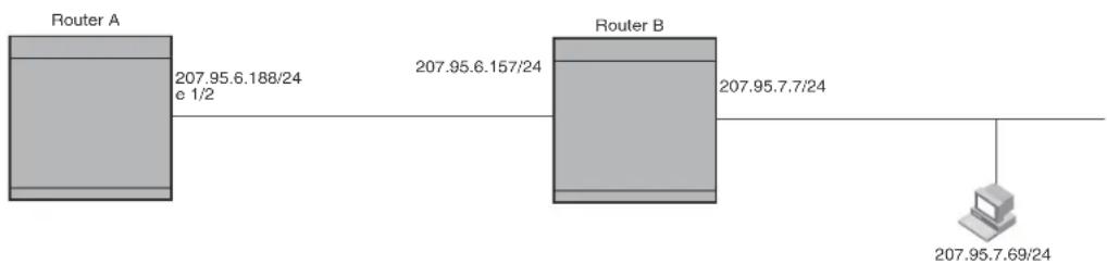
flowchart
graph LR
    A["Router A\n207.95.6.188/24 e 1/2"] --> B["Router B\n207.95.6.157/24"]
    B --> C["Terminal\n207.95.7.69/24"]
The following command configures a static route to 207.95.7.0, using 207.95.6.157 as the next-hop gateway.
BigIron RX(config)# ip route 207.95.7.0/24 207.95.6.157
When you configure a static IP route, you specify the destination address for the route and the next-hop gateway or device interface through which the device can reach the route. The device adds the route to the IP route table. In this case, Router A knows that 207.95.6.157 is reachable through port 1/2, and also assumes that local interfaces within that subnet are on the same port. Router A deduces that IP interface 207.95.7.188 is also on port 1/2.
The software automatically removes a static IP route from the IP route table if the port used by that route becomes unavailable. When the port becomes available again, the software automatically re-adds the route to the IP route table.
Configuring a static IP route
To configure an IP static route with a destination address of 192.0.0.0 255.0.0.0 and a next-hop router IP address of 195.1.1.1, enter the following.
BigIron RX(config)# ip route 192.0.0.0 255.0.0.0 195.1.1.1
To configure a default route, enter the following.
BigIron RX(config)# ip route 0.0.0.0 0.0.0.0
To configure a static IP route with an Ethernet port instead of a next-hop address, enter a command such as the following.
BigIron RX(config)# ip route 192.128.2.69 255.255.255.0 ethernet 4/1
The command configures a static IP route for destination network 192.128.2.69/24. Since an Ethernet port is specified instead of a gateway IP address as the next hop, the device always forwards traffic for the 192.128.2.69/24 network to port 4/1.
To configure an IP static route that uses virtual interface 3 as its next hop, enter a command such as the following:
BigIron RX(config)# ip route 192.128.2.71 255.255.255.0 ve 3
Syntax: ip route
The
The
For a default route, enter 0.0.0.0 0.0.0.0 xxx.xxx.xxx.xxx (use 0 for the
If you do not want to specify a next-hop IP address, you can instead specify a port or interface number on the device. The
NOTE
The port or virtual interface you use for the static route's next hop must have at least one IP address configured on it. The address does not need to be in the same subnet as the destination network.
The
NOTE
If you specify 16, RIP considers the metric to be infinite and thus also considers the route to be unreachable.
The tag
The distance
NOTE
The device will replace the static route if it receives a route with a lower administrative distance. Refer to “Changing administrative distances” on page 767 for a list of the default administrative distances for all types of routes.
Configuring a "null" route
You can configure the device to drop IP packets to a specific network or host address by configuring a "null" (sometimes called "null0") static route for the address. When the device receives a packet destined for the address, the device drops the packet instead of forwarding it.
To configure a null static route to drop packets destined for network 209.157.22.x, enter the following commands.
BigIron RX(config)# ip route 209.157.22.0 255.255.255.0 null0 BigIron RX(config)# write memory
Syntax: ip route
To display the maximum value for your device, enter the show default values command. The maximum number of static IP routes the system can hold is listed in the ip-static-route row in the System Parameters section of the display. To change the maximum value, use the system-max ip-static-route
The
The
The null0 parameter indicates that this is a null route. You must specify this parameter to make this a null route.
The
The tag
The distance
NOTE
The last three parameters are optional and do not affect the null route, unless you configure the administrative distance to be 255. In this case, the route is not used and the traffic might be forwarded instead of dropped.
Dropping traffic sent to the null0 interface in hardware
Traffic sent to the null0 interface is done in hardware; that is, by programming the CAM to discard traffic sent to the null0 interface. This improves forwarding efficiency and reduces the burden on the device's CPU.
Hardware dropping for IP traffic sent to the null0 interface is supported.
You can optionally configure the device to drop traffic sent to the default IP route address in hardware. To do this, enter the following commands.
BigIron RX(config)# ip route 0.0.0.0 0.0.0.0 null0
BigIron RX(config)# ip hw-drop-on-def-route
Syntax: [no] ip hw-drop-on-def-route
Configuring the device to drop traffic sent to the default IP route address in hardware causes the device to program 32-bit host CAM entries for each destination address using the default route, which could consume the CAM space. To prevent this from happening, you can enable the CAM Default Route Aggregation feature. To do this, enter the following command:
BigIron RX(config)# ip dr-aggregate
Syntax: ip dr-aggregate
Static route tagging
Static routes can be configured with a tag value, which can be used to color routes and filter routes during a redistribution process. When tagged static routes are redistributed to OSPF or to a protocol that can carry tag information, they are redistributed with their tag values.
To add a tag value to a static route, enter commands such as the following:
BigIron RX(config)#ip route 192.122.12.1 255.255.255.0 192.122.1.1 tag 20
Syntax: ip route
The
The
Enter 0 - 4294967295 for tag
Configuring load balancing and redundancy using multiple static routes to the same destination
You can configure multiple static IP routes to the same destination, for the following benefits:
- IP load sharing – If you configure more than one static route to the same destination, and the routes have different next-hop gateways but have the same metrics, the device load balances among the routes using basic round-robin. For example, if you configure two static routes with the same metrics but to different gateways, the device alternates between the two routes. For information about IP load balancing, refer to “Configuring IP load sharing” on page 209.
- Backup Routes – If you configure multiple static IP routes to the same destination, but give the routes different next-hop gateways and different metrics, the device will always use the route with the lowest metric. If this route becomes unavailable, the device will fail over to the static route with the next-lowest metric, and so on.
NOTE
You also can bias the device to select one of the routes by configuring them with different administrative distances. However, make sure you do not give a static route a higher administrative distance than other types of routes, unless you want those other types to be preferred over the static route. For a list of the default administrative distances, refer to “Changing administrative distances” on page 767.
The steps for configuring the static routes are the same as described in the previous section. The following sections provide examples.
To configure multiple static IP routes, enter commands such as the following.
BigIron RX(config)# ip route 192.128.2.69 255.255.255.0 209.157.22.1 BigIron RX(config)# ip route 192.128.2.69 255.255.255.0 192.111.10.1
The commands in the example above configure two static IP routes. The routes go to different next-hop gateways but have the same metrics. These commands use the default metric value (1), so the metric is not specified. These static routes are used for load sharing among the next-hop gateways.
The following commands configure static IP routes to the same destination, but with different metrics. The route with the lowest metric is used by default. The other routes are backups in case the first route becomes unavailable. The device uses the route with the lowest metric if the route is available.
BigIron RX(config)# ip route 192.128.2.69 255.255.255.0 209.157.22.1 BigIron RX(config)# ip route 192.128.2.69 255.255.255.0 192.111.10.1 2 BigIron RX(config)# ip route 192.128.2.69 255.255.255.0 201.1.1.1 3
In this example, each static route has a different metric. The metric is not specified for the first route, so the default (1) is used. A metric is specified for the second and third static IP routes. The second route has a metric of two and the third route has a metric of 3. Thus, the second route is used only of the first route (which has a metric of 1) becomes unavailable. Likewise, the third route is used only if the first and second routes (which have lower metrics) are both unavailable.
For complete syntax information, refer to "Configuring a static IP route" on page 201.
Configuring standard static IP routes and interface or null static routes to the same destination
You can configure a null0 or interface-based static route to a destination and also configure a normal static route to the same destination, so long as the route metrics are different.
When the device has multiple routes to the same destination, the device always prefers the route with the lowest metric. Generally, when you configure a static route to a destination network, you assign the route a low metric so that the device prefers the static route over other routes to the destination.
This feature is especially useful for the following configurations. These are not the only allowed configurations but they are typical uses of this enhancement:
- When you want to ensure that if a given destination network is unavailable, the device drops (forwards to the null interface) traffic for that network instead of using alternate paths to route the traffic. In this case, assign the normal static route to the destination network a lower metric than the null route.
- When you want to use a specific interface by default to route traffic to a given destination network, but want to allow the device to use other interfaces to reach the destination network if the path that uses the default interface becomes unavailable. In this case, give the interface route a lower metric than the normal static route.
NOTE
You cannot add a null or interface-based static route to a network if there is already a static route of any type with the same metric you specify for the null or interface-based route.
Figure 11 shows an example of two static routes configured for the same destination network. One of the routes is a standard static route and has a metric of 1. The other static route is a null route and has a higher metric than the standard static route. The device always prefers the static route with the lower metric. In this example, the device always uses the standard static route for traffic to destination network 192.168.7.0/24, unless that route becomes unavailable, in which case the device sends traffic to the null route instead.
FIGURE 11 Standard and null static routes to the same destination network

flowchart
graph TD
    A["Router A"] -->|192.168.6.188/24 192.168.6.157/24| B["Router B"]
    B --> C["Router A"]
    B --> D["Router B"]
    D --> E["Router A"]
    D --> F["Router B"]
    F --> G["Router A"]
    F --> H["Router B"]
    H --> I["Router A"]
    style A fill:#ccc
    style B fill:#ccc
    style D fill:#ccc
    style F fill:#ccc
    style G fill:#ccc
    style H fill:#ccc
    style I fill:#ccc
Figure 12 shows another example of two static routes. A standard static route and an interface-based static route are configured for destination network 192.168.6.0/24. The interface-based static route has a lower metric than the standard static route. As a result, the device always prefers the interface-based route when the route is available. However, if the interface-based route becomes unavailable, the device still forwards the traffic toward the destination using an alternate route through gateway 192.168.8.11/24.
FIGURE 12 Standard and interface routes to the same destination network

flowchart
graph TD
    A["Router A\n192.168.6.188/24 Port1/1"] -->|When route through interface 1/1 is available, Router A always uses that route.| B["Router B\n192.168.8.11/24"]
    B -->|If route through interface 1/1 becomes unavailable, Router A uses alternate route through gateway 192.168.8.11/24.| C["Router C\nRouter C"]
    C --> D["Router D\n192.168.6.69/24"]
    D --> E["Router D"]
    style A fill:#f9f,stroke:#333
    style B fill:#ccf,stroke:#333
    style C fill:#cfc,stroke:#333
    style D fill:#fcc,stroke:#333
To configure a standard static IP route and a null route to the same network as shown in Figure 11 on page 206, enter commands such as the following.
BigIron RX(config)# ip route 192.168.7.0/24 192.168.6.157/24 1
BigIron RX(config)# ip route 192.168.7.0/24 null0 3
The first command configures a standard static route, which includes specification of the next-hop gateway. The command also gives the standard static route a metric of 1, which causes the device to always prefer this route when the route is available.
The second command configures another static route for the same destination network, but the second route is a null route. The metric for the null route is 3, which is higher than the metric for the standard static route. If the standard static route is unavailable, the software uses the null route.
For complete syntax information, refer to "Configuring a static IP route" on page 201.
To configure a standard static route and an interface-based route to the same destination, enter commands such as the following.
BigIron RX(config)# ip route 192.168.6.0/24 ethernet 1/1 1 BigIron RX(config)# ip route 192.168.6.0/24 192.168.8.11/24 3
The first command configured an interface-based static route through Ethernet port 1/1. The command assigns a metric of 1 to this route, causing the device to always prefer this route when it is available. If the route becomes unavailable, the device uses an alternate route through the next-hop gateway 192.168.8.11/24.
Configuring a default network route
The device enables you to specify a candidate default route without the need to specify the next hop gateway. If the IP route table does not contain an explicit default route (for example, 0.0.0.0/0) or propagate an explicit default route through routing protocols, the software can use the default network route as a default route instead.
When the software uses the default network route, it also uses the default network route's next hop gateway as the gateway of last resort.
This feature is especially useful in environments where network topology changes can make the next hop gateway unreachable. This feature allows the device to perform default routing even if the default network route's default gateway changes.
The feature thus differs from standard default routes. When you configure a standard default route, you also specify the next hop gateway. If a topology change makes the gateway unreachable, the default route becomes unusable.
For example, if you configure 10.10.10.0/24 as a candidate default network route, if the IP route table does not contain an explicit default route (0.0.0.0/0), the software uses the default network route and automatically uses that route's next hop gateway as the default gateway. If a topology change occurs and as a result the default network route's next hop gateway changes, the software can still use the default network route.
If you configure more than one default network route, the device uses the following algorithm to select one of the routes.
-
Use the route with the lowest administrative distance.
-
If the administrative distances are equal:
-
Are the routes from different routing protocols (RIP, OSPF, or BGP4)? If so, use the route with the lowest IP address.
- If the routes are from the same routing protocol, use the route with the best metric. The meaning of "best" metric depends on the routing protocol:
- RIP – The metric is the number of hops (additional routers) to the destination. The best route is the route with the fewest hops.
- OSPF - The metric is the path cost associated with the route. The path cost does not indicate the number of hops but is instead a numeric value associated with each route. The best route is the route with the lowest path cost.
- BGP4 – The metric is the Multi-exit Discriminator (MED) associated with the route. The MED applies to routes that have multiple paths through the same AS. The best route is the route with the lowest MED.
Configuring a default network route
You can configure up to four default network routes. To configure a default network route, enter commands such as the following:
BigIron RX(config)# ip default-network 209.157.22.0
BigIron RX(config)# write memory
Syntax: ip default-network
The
To verify that the route is in the route table, enter the following command at any level of the CLI.
| BigIron RX(config)# show ip route | |||||
| Total number of IP routes: 2 | |||||
| Start index: 1 B:BGP D:Connected R:RIP S:Static O:OSPF *:Candidate default | |||||
| Destination | Gateway | Port | Cost | Type | |
| 1 | 209.157.20.0 | 0.0.0.0 | lb1 | 1 | D |
| 2 | 209.157.22.0 | 0.0.0.0 | 4/11 | 1 | *D |
This example shows two routes. Both of the routes are directly attached, as indicated in the Type column. However, one of the routes is shown as type “*D”, with an asterisk (*). The asterisk indicates that this route is a candidate default network route.
Configuring IP load sharing
The IP route table can contain more than one path to a given destination. When this occurs, the device selects the path with the lowest cost as the path for forwarding traffic to the destination. If the IP route table contains more than one path to a destination and the paths each have the lowest cost, then the device uses IP load sharing to select a path to the destination. ^1
IP load sharing is based on the destination address of the traffic. device supports load sharing based on individual host addresses or on network addresses.
You can enable a device to load balance across up to eight equal-cost paths. The default maximum number of equal-cost load sharing paths is four.
NOTE
IP load sharing is not based on source routing, only on next-hop routing.
NOTE
The term “path” refers to the next-hop router to a destination, not to the entire route to a destination. Thus, when the software compares multiple equal-cost paths, the software is comparing paths that use different next-hop routers, with equal costs, to the same destination.
In many contexts, the terms “route” and “path” mean the same thing. Most of the user documentation uses the term “route” throughout. The term “path” is used in this section to refer to an individual next-hop router to a destination, while the term “route” refers collectively to the multiple paths to the destination. Load sharing applies when the IP route table contains multiple, equal-cost paths to a destination.
How multiple equal-cost paths enter the IP Route table
IP load sharing applies to equal-cost paths in the IP route table. Routes eligible for load sharing can enter the table from the following sources:
- IP static routes
-
Routes learned through RIP, OSPF, and BGP4
-
IP load sharing is also called "Equal-Cost Multi-Path (ECMP)" load sharing or just "ECMP"
Administrative distance
The administrative distance is a unique value associated with each type (source) of IP route. Each path has an administrative distance. It is used when evaluating multiple equal-cost paths to the same destination from different sources, such as RIP, OSPF and so on, but not used when performing IP load sharing.
The value of the administrative distance is determined by the source of the route. The device is configured with a unique administrative distance value for each IP route source.
When the software receives paths from different sources to the same destination, the software compares their administrative distances, selects the one with the lowest distance, and puts it in the IP route table. For example, if the device has a path learned from OSPF and a path learned from RIP for a given destination, only the path with the lower administrative distance enters the IP route table.
Here are the default administrative distances on the device:
- Directly connected - 0 (this value is not configurable)
- Static IP route - 1 (applies to all static routes, including default routes and default network routes)
- Exterior Border Gateway Protocol (EBGP) - 20
- OSPF - 110
- RIP - 120
- Interior Gateway Protocol (IBGP) - 200
- Local BGP - 200
- Unknown – 255 (the router will not use this route)
Lower administrative distances are preferred over higher distances. For example, if the router receives routes for the same network from OSPF and from RIP, the router will prefer the OSPF route by default.
NOTE
You can change the administrative distances individually. Refer to the configuration chapter for the route source for information.
Since the software selects only the path with the lowest administrative distance, and the administrative distance is determined by the path's source, IP load sharing does not apply to paths from different route sources. IP load sharing applies only when the IP route table contains paths from the same IP route source to the same destination.
Path cost
The cost parameter provides a basis of comparison for selecting among paths to a given destination. Each path in the IP route table has a cost. When the IP route table contains multiple paths to a destination, the device chooses the path with the lowest cost. When the IP route table contains more than one path with the lowest cost to a destination, the device uses IP load sharing to select one of the lowest-cost paths.
The source of a path's cost value depends on the source of the path:
- IP static route – The value you assign to the metric parameter when you configure the route. The default metric is 1. Refer to “Configuring load balancing and redundancy using multiple static routes to the same destination” on page 203.
-
RIP – The number of next-hop routers to the destination.
-
OSPF – The Path Cost associated with the path. The paths can come from any combination of inter-area, intra-area, and external Link State Advertisements (LSAs).
- BGP4 – The path's Multi-Exit Discriminator (MED) value.
NOTE
If the path is redistributed between two or more of the above sources before entering the IP route table, the cost can increase during the redistribution due to settings in redistribution filters.
Static route, OSPF, and BGP4 load sharing
IP load sharing and load sharing for static routes, OSPF routes, and BGP4 routes are individually configured. Multiple equal-cost paths for a destination can enter the IP route table only if the source of the paths is configured to support multiple equal-cost paths. For example, if BGP4 allows only one path with a given cost for a given destination, the BGP4 route table cannot contain equal-cost paths to the destination. Consequently, the IP route table will not receive multiple equal-cost paths from BGP4.
Table 50 lists the default and configurable maximum numbers of paths for each IP route source that can provide equal-cost paths to the IP route table. The table also lists where to find configuration information for the route source's load sharing parameters.
The load sharing state for all the route sources is based on the state of IP load sharing. Since IP load sharing is enabled by default on the device, load sharing for static IP routes, RIP routes, OSPF routes, and BGP4 routes also is enabled by default.
TABLE 50 Default load sharing parameters for route sources
| Route source Default maximum number of paths Maximum number of paths See... | |||
| Static IP route 4 | NOTE: This value depends on the value for IP load sharing, and is not separately configurable. | 8NOTE: This value depends on the value for IP load sharing, and is not separately configurable. | page 212 |
| RIP 4 | NOTE: This value depends on the value for IP load sharing, and is not separately configurable. | 8NOTE: This value depends on the value for IP load sharing, and is not separately configurable. | page 212 |
| OSPF 4 8 | page 212 | ||
| BGP4 | 1 | 4 | page 791 |
How IP load sharing works
On the device, IP load sharing (also known as ECMP load sharing) is done by the hardware. If there is more than one path to a given destination, a hash is calculated based on the source MAC address, destination MAC address, source IP address, destination IP address, and IP protocol. This hash is used to select one of the paths.
Changing the maximum number of load sharing paths
By default, IP load sharing allows IP traffic to be balanced across up to four equal path. You can change the maximum number of paths that the device supports to a value of 2 - 8.
For optimal results, set the maximum number of paths to a value equal to or greater than the maximum number of equal-cost paths that your network typically contains. For example, if the device has six next-hop routers, set the maximum paths value to six.
NOTE
If the setting for the maximum number of paths is lower than the actual number of equal-cost paths, the software does not use all the paths for load sharing.
To change the number of paths, enter a command such as the following.
BigIron RX(config)# ip load-sharing 8
Syntax: [no] ip load-sharing [
Enter a value from 2 - 8 for
Response to path state changes
If one of the load-balanced paths becomes unavailable, the IP route table in hardware is modified to stop using the unavailable path. The traffic is load balanced between the available paths using the same hashing mechanism described above. (Refer to “How IP load sharing works” on page 211.)
Default route ECMP
On the BigIron RX, IP load sharing (also known as ECMP load sharing) is done by the hardware. If there is more than one path to a given destination, a hash is calculated based on the source MAC address, destination MAC address, source IP address, destination IP address, and IP protocol. This hash is used to select one of the paths.
If there are multiple next-hop routers for the default route in the IPv4 routing table, routed packets on the default route would be automatically load-balanced among these next-hops through a hashing formula, calculated based on (IPv4 Destination Address, IPv4 Source Address, IPv4 Source Port, IPv4 Destination Port, DA-MAC, and SA-MAC) of the packets received. This feature allows for load distribution of traffic among the available default route next-hops.
NOTE
This feature is currently not applicable to IPv6 traffic.
To specify the ECMP default route, enter a command such as the following.
BigIron RX(config)# ip load-sharing default-route
Syntax: [no] ip load-sharing [
The
The
Displaying the ECMP load sharing
Use the show run command to display the ECMP load sharing.
BigIron RX(config)#show run
==================show run ====================
!
logging console
hostname RW
ip route 0.0.0.0/0 100.1.1.2
ip route 0.0.0.0/0 100.1.2.2
ip route 0.0.0.0/0 100.1.3.2
ip route 0.0.0.0/0 100.1.4.2
ip route 10.0.0.0/8 10.43.2.1
ip route 40.0.0.0/24 100.1.1.2
ip load-sharing default-route
Use the show ip route command to display the traffic that will now be sent over all 4 links load balanced instead of being on only 1 link.
BigIron RX#show ip route
Total number of IP routes: 9
Type Codes - B:BGP D:Connected I:ISIS S:Static R:RIP O:OSPF; Cost - Dist/Metric
Destination Gateway Port Cost Type
1 0.0.0.0/0 100.1.1.2 eth 7/1 1/1 S
0.0.0.0/0 100.1.2.2 eth 7/2 1/1 S
0.0.0.0/0 100.1.3.2 eth 7/3 1/1 S
0.0.0.0/0 100.1.4.2 eth 7/4 1/1 S
2 10.0.0.0/8 10.43.2.1 mgmt 1 1/1 S
3 10.43.2.0/24 DIRECT mgmt 1 0/0 D
4 40.0.0.0/24 100.1.1.2 eth 7/1 1/1 S
5 70.1.1.0/24 DIRECT eth 7/9 0/0 D
6 100.1.1.0/24 DIRECT eth 7/1 0/0 D
7 100.1.2.0/24 DIRECT eth 7/2 0/0 D
8 100.1.3.0/24 DIRECT eth 7/3 0/0 D
9 100.1.4.0/24 DIRECT eth 7/4 0/0 D
IP receive access list
The IP receive access list feature uses IPv4 ACLs to filter the packets intended for the management process to protect the management module from being overloaded with heavy traffic that was sent to one of the Layer 3 Switch IP interfaces. The feature applies to IPv4 unicast and multicast packets.
Configuring IP receive access list
IP receive access list is a global configuration command. Once it is applied, the command will be effective on all the management modules on the device. To configure the feature, do the following.
- Create a numbered ACL that will be used as the IP receive ACL. This ACL can be a standard (1-99) or extended (100-199) ACL. Named ACLs are not supported.
BigIron RX(config)# access-list 10 deny host 209.157.22.26 log
BigIron RX(config)# access-list 10 deny 209.157.29.12 log
BigIron RX(config)# access-list 10 deny host IPHost1 log
BigIron RX(config)# access-list 10 permit any
BigIron RX(config)# write memory
- Configure ACL 10 as the IP receive access list by entering the following command.
BigIron RX(config)# ip receive access-list 10
Syntax: [no] ip receive access-list
Specify an access list number for
The IP receive ACL is applied globally to all interfaces on the device.
Displaying IP receive access list
To determine if IP receive access list has been configured on the device, enter the following command.
BigIron RX# show access-list bindings L4 configuration:
ip receive access-list 101
Configuring IRDP
The device uses ICMP Router Discovery Protocol (IRDP) to advertise the IP addresses of its router interfaces to directly attached hosts. IRDP is disabled by default. You can enable it globally or on individual port:
- If you enable IRDP globally, all ports use the default values for the IRDP parameters.
- If you leave IRDP disabled globally but enable it on individual ports, you also can configure the IRDP parameters on an individual port basis.
NOTE
You can configure IRDP parameters only an individual port basis. To do so, IRDP must be disabled globally and enabled only on individual ports. You cannot configure IRDP parameters if the feature is globally enabled.
When IRDP is enabled, the device periodically sends Router Advertisement messages out the IP interfaces on which the feature is enabled. The messages advertise the device's IP addresses to directly attached hosts who listen for the messages. In addition, hosts can be configured to query the device for the information by sending Router Solicitation messages.
Some types of hosts use the Router Solicitation messages to discover their default gateway. When IRDP is enabled, the device responds to the Router Solicitation messages. Some clients interpret this response to mean that the device is the default gateway. If another router is actually the default gateway for these clients, leave IRDP disabled on the device.
IRDP uses the following parameters. If you enable IRDP on individual ports rather than globally, you can configure these parameters on an individual port basis using:
- Packet type – The device can send Router Advertisement messages as IP broadcasts or as IP multicasts addressed to IP multicast group 224.0.0.1. The packet type is IP broadcast.
-
Maximum message interval and minimum message interval – When IRDP is enabled, the device sends the Router Advertisement messages every 450 – 600 seconds by default. The time within this interval that the device selects is random for each message and is not affected by traffic loads or other network factors. The random interval minimizes the probability that a host will receive Router Advertisement messages from other routers at the same time. The interval on each IRDP-enabled device interface is independent of the interval on other IRDP-enabled interfaces. The default maximum message interval is 600 seconds. The default minimum message interval is 450 seconds.
-
Hold time – Each Router Advertisement message contains a hold time value. This value specifies the maximum amount of time the host should consider an advertisement to be valid until a newer advertisement arrives. When a new advertisement arrives, the hold time is reset. The hold time is always longer than the maximum advertisement interval. Therefore, if the hold time for an advertisement expires, the host can reasonably conclude that the router interface that sent the advertisement is no longer available. The default hold time is three times the maximum message interval.
- Preference – If a host receives multiple Router Advertisement messages from different routers, the host selects the router that sent the message with the highest preference as the default gateway. The preference can be a number from 4294967296 to 4294967295. The default is 0.
Enabling IRDP globally
To globally enable IRDP, enter the following command.
BigIron RX(config)# ip irdp
This command enables IRDP on the IP interfaces on all ports. Each port uses the default values for the IRDP parameters. The parameters are not configurable when IRDP is globally enabled.
Enabling IRDP on an individual port
To enable IRDP on an individual interface and change IRDP parameters, enter commands such as the following.
BigIron RX(config)# interface ethernet 1/3
BigIron RX(config-if-e10000-1/3)# ip irdp maxadvertinterval 400
This example shows how to enable IRDP on a specific port and change the maximum advertisement interval for Router Advertisement messages to 400 seconds.
NOTE
To enable IRDP on individual ports, you must leave the feature globally disabled.
Syntax: [no] ip irdp [broadcast | multicast] [holdtime
The broadcast | multicast parameter specifies the packet type the device uses to send Router Advertisement.
- broadcast – The device sends Router Advertisement as IP broadcasts. This is the default.
- multicast – The device sends Router Advertisement as multicast packets addressed to IP multicast group 224.0.0.1.
The holdtime
The maxadvertinterval parameter specifies the maximum amount of time the device waits between sending Router Advertisements. You can specify a value from 1 to the current value of the holdtime parameter. The default is 600 seconds.
The minadvertinterval parameter specifies the minimum amount of time the device can wait between sending Router Advertisements. The default is three-fourths (0.75) the value of the maxadvertinterval parameter. If you change the maxadvertinterval parameter, the software automatically adjusts the minadvertinterval parameter to be three-fourths the new value of the maxadvertinterval parameter. If you want to override the automatically configured value, you can specify an interval from 1 to the current value of the maxadvertinterval parameter.
The preference
Configuring UDP broadcast and IP helper parameters
Some applications rely on client requests sent as limited IP broadcasts addressed to the UDP's application port. If a server for the application receives such a broadcast, the server can reply to the client. Routers do not forward subnet directed broadcasts, so the client and server must be on the same network for the broadcast to reach the server. If the client and server are on different networks (on opposite sides of a router), the client's request cannot reach the server.
To configure the device to forward clients' requests to UDP application servers:
- Enable forwarding support for the UDP application port, if forwarding support is not already enabled.
- Configure a helper address on the interface connected to the clients. Specify the helper address to be the IP address of the application server or the subnet directed broadcast address for the IP subnet the server is in. A helper address is associated with a specific interface and applies only to client requests received on that interface. The device forwards client requests for any of the application ports the device is enabled to forward to the helper address.
Forwarding support for the following application ports is enabled by default:
The application names are the names for these applications that the device recognizes, and might not match the names for these applications on some third-party devices. The numbers listed in parentheses are the UDP port numbers for the applications. The numbers come from RFC 1340.
NOTE
As shown above, forwarding support for BootP/DHCP is enabled by default. If you are configuring the device to forward BootP/DHCP requests, refer to “Configuring BootP/DHCP forwarding parameters” on page 218.
You can enable forwarding for other applications by specifying the application port number.
You also can disable forwarding for an application.
NOTE
If you disable forwarding for a UDP application, forwarding of client requests received as broadcasts to helper addresses is disabled. Disabling forwarding of an application does not disable other support for the application. For example, if you disable forwarding of Telnet requests to helper addresses, other Telnet support on the device is not also disabled.
Enabling forwarding for a UDP application
If you want the device to forward client requests for UDP applications that the device does not forward by default, you can enable forwarding support for the port. To enable forwarding support for a UDP application, use either of the following methods. You also can disable forwarding for an application using these methods.
NOTE
You also must configure a helper address on the interface that is connected to the clients for the application. The device cannot forward the requests unless you configure the helper address. Refer to "Configuring an IP helper address" on page 219.
To enable the forwarding of SNMP trap broadcasts, enter the following command.
BigIron RX(config)# ip forward-protocol udp snmp-trap
Syntax: [no] ip forward-protocol udp
The
In addition, you can specify any UDP application by using the application's UDP port number.
The
To disable forwarding for an application, enter a command such as the following.
BigIron RX(config)# no ip forward-protocol udp snmp
Syntax: [no] ip forward-protocol udp snmp
This command disables forwarding of SNMP requests to the helper addresses configured on device interfaces.
Configuring an IP helper address
To forward a client's broadcast request for a UDP application when the client and server are on different networks, you must configure a helper address on the interface connected to the client. Specify the server's IP address or the subnet directed broadcast address of the IP subnet the server is in as the helper address.
You can configure up to 16 helper addresses on each interface. You can configure a helper address on an Ethernet port or a virtual interface.
To configure a helper address on interface 2 on device module 1, enter the following commands.
BigIron RX(config)# interface e 1/2 BigIron RX(config-if-e1000-1/2)# ip helper-address 207.95.7.6
The commands in this example change the CLI to the configuration level for port 1/2, then add a helper address for server 207.95.7.6 to the port. If the port receives a client request for any of the applications that the device is enabled to forward, the device forwards the client's request to the server.
Syntax: ip helper-address
The
Configuring BootP/DHCP forwarding parameters
The DHCP relay will allow for IP address grants that do not match the subnets configured on the interface that the DHCP request was received. A host on an IP network can use BootP/DHCP to obtain its IP address from a BootP/DHCP server. To obtain the address, the client sends a BootP/DHCP request. The request is a subnet directed broadcast and is addressed to UDP port 67. A limited IP broadcast is addressed to IP address 255.255.255.255 and is not forwarded by the device or other IP routers.
When the BootP/DHCP client and server are on the same network, the server receives the broadcast request and replies to the client. However, when the client and server are on different networks, the server does not receive the client's request, because the device does not forward the request.
You can configure the device to forward BootP/DHCP requests. To do so, configure a helper address on the interface that receives the client requests, and specify the BootP/DHCP server's IP address as the address you are helping the BootP/DHCP requests to reach. Instead of the server's IP address, you can specify the subnet directed broadcast address of the IP subnet the server is in.
NOTE
The IP subnet configured on the port which is directly connected to the device sending a BootP/DHCP request, does not have to match the subnet of the IP address given by the DHCP server.
BootP/DHCP forwarding parameters
The following parameters control the device's forwarding of BootP/DHCP requests:
- Helper address – The BootP/DHCP server's IP address. You must configure the helper address on the interface that receives the BootP/DHCP requests from the client. The device cannot forward a request to the server unless you configure a helper address for the server.
- Gateway address – The device places the IP address of the interface that received the BootP/DHCP request in the request packet's Gateway Address field (sometimes called the Router ID field). When the server responds to the request, the server sends the response as a unicast packet to the IP address in the Gateway Address field. (If the client and server are directly attached, the Gateway ID field is empty and the server replies to the client using a unicast or broadcast packet, depending on the server.)
By default, the device uses the lowest-numbered IP address on the interface that receives the request as the Gateway address. You can override the default by specifying the IP address you want the device to use.
- Hop Count – Each router that forwards a BootP/DHCP packet increments the hop count by 1. Routers also discard a forwarded BootP/DHCP request instead of forwarding the request if the hop count is greater than the maximum number of BootP/DHCP hops allows by the router. By default, the device forwards a BootP/DHCP request if its hop count is four or less, but discards the request if the hop count is greater than four. You can change the maximum number of hops the device will allow to a value from 1 – 15.
NOTE
The BootP/DHCP hop count is not the TTL parameter.
Configuring an IP helper address
The procedure for configuring a helper address for BootP/DHCP requests is the same as the procedure for configuring a helper address for other types of UDP broadcasts. Refer to "Configuring an IP helper address" on page 218.
Changing the IP address used for stamping BootP/DHCP requests
When the device forwards a BootP/DHCP request, the device "stamps" the Gateway Address field. The default value the device uses to stamp the packet is the lowest-numbered IP address configured on the interface that received the request.
The BootP/DHCP stamp address is an interface parameter. Change the parameter on the interface that is connected to the BootP/DHCP client.
To change the IP address used for stamping BootP/DHCP requests received on interface 1/1, enter commands such as the following.
BigIron RX(config)# int e 1/1
BigIron RX(config-if-e1000-1/1)# ip bootp-gateway 109.157.22.26
These commands change the CLI to the configuration level for port 1/1, then change the BootP/DHCP stamp address for requests received on port 1/1 to 192.157.22.26. The device will place this IP address in the Gateway Address field of BootP/DHCP requests that the device receives on port 1/1 and forwards to the BootP/DHCP server.
Syntax: ip bootp-gateway
Changing the maximum number of hops to a BootP relay server
Each BootP/DHCP request includes a field Hop Count field. The Hop Count field indicates how many routers the request has passed through. When the device receives a BootP/DHCP request, the device looks at the value in the Hop Count field:
- If the hop count value is equal to or less than the maximum hop count the device allows, the device increments the hop count by one and forwards the request.
- If the hop count is greater than the maximum hop count the device allows, the device discards the request.
NOTE
The BootP/DHCP hop count is not the TTL parameter.
To modify the maximum number of BootP/DHCP hops, enter the following command.
BigIron RX(config)# bootp-relay-max-hops 10
This command allows the device to forward BootP/DHCP requests that have passed through up to ten previous hops before reaching the device.
Syntax: bootp-relay-max-hops <1-15>
Default: 4
Displaying IP information
You can display the following IP configuration information statistics:
- Global IP parameter settings – refer to “Displaying global IP configuration information” on page 221.
- IP interfaces – refer to “Displaying IP interface information” on page 223.
- ARP entries – refer to “Displaying ARP entries” on page 224.
- Static ARP entries – refer to “Displaying ARP entries” on page 224.
- IP forwarding cache – refer to “Displaying the forwarding cache” on page 226.
- IP route table – refer to “Displaying the IP route table” on page 228.
- IP traffic statistics – refer to “Displaying IP traffic statistics” on page 231.
The sections below describe how to display this information.
In addition to the information described below, you can display the following IP information. This information is described in other parts of this guide:
- RIP information – refer to “Displaying RIP filters” on page 676.
- OSPF information – refer to “Displaying OSPF information” on page 720.
- BGP4 information – refer to “Displaying BGP4 information” on page 824.
- DVMRP information – refer to “Displaying information about an upstream neighbor device” on page 655
- PIM information – refer to “Displaying PIM Sparse configuration information and statistics” on page 615.
- VRRP or VRRPE information – refer to “Displaying VRRP and VRRPE information” on page 467.
Displaying global IP configuration information
To display IP configuration information, enter the following command at any CLI level.
BigIron RX> show ip
Global Settings
ttl: 64, arp-age: 10, bootp-relay-max-hops: 4
router-id : 207.95.11.128
enabled : UDP-Broadcast-Forwarding IRDP Proxy-ARP OSPF
disabled: BGP4 Load-Sharing RIP DVMRP FSRP VRRP
Static Routes
Index IP Address Subnet Mask Next Hop Router Metric Distance
1 0.0.0.0 0.0.0.0 209.157.23.2 1 1
Policies
Index Action Source Destination Protocol Port Operator
1 deny 209.157.22.34 209.157.22.26 tcp http =
64 permit any any
Syntax: show ip
NOTE
This command has additional options, which are explained in other sections in this guide, including the sections below this one.
This display shows the following information.
TABLE 51 CLI display of global IP configuration information
| This field... Displays... | |
| Global settings | |
| ttl The Time-To-Live (TTL) for IP packets. The TTL specifies the maximum number of router hops a packet can travel before reaching the device. If the packet's TTL value is higher than the value specified in this field, the Brocade router drops the packet.To change the maximum TTL, refer to “Changing the TTL threshold” on page 194. |
arp-age The ARP aging period. This parameter specifies how many minutes an
inactive ARP entry remains in the ARP cache before the router ages out the entry.
To change the ARP aging period, refer to “Changing the ARP aging period” on page 190.
TABLE 51 CLI display of global IP configuration information (Continued)
| This field... | Displays... |
| bootp-relay-max-hops | The maximum number of hops away a BootP server can be located from the Brocade router and still be used by the router's clients for network booting. To change this value, refer to “Changing the maximum number of hops to a BootP relay server” on page 220. |
| router-id The 32-bit number that uniquely identifies the Brocade router.By default, the router ID is the numerically lowest IP interface configured on the router. To change the router ID, refer to “Changing the router ID” on page 182. | |
| enabled The IP-related protocols that are enabled on the router. | |
| disabled The IP-related protocols that are disabled on the router. | |
| Static routes | |
| Index The row number of this entry in the IP route table. | |
| IP Address The IP address of the route's destination. | |
| Subnet Mask The network mask for the IP address. | |
| Next Hop Router The IP address of the router interface to which the Brocade router sends packets for the route. | |
| Metric The cost of the route. Usually, the metric represents the number of hops to the destination. | |
| Distance The administrative distance of the route. The default administrative distance for static IP routes in Brocade routers is 1.To list the default administrative distances for all types of routes or to change the administrative distance of a static route, refer to “Changing administrative distances” on page 767. | |
| Policies | |
| Index The policy number. This is the number you assigned the policy when you configured it. | |
| Action The action the router takes if a packet matches the comparison values in the policy. The action can be one of the following:deny - The router drops packets that match this policy.permit - The router forwards packets that match this policy. | |
| Source | The source IP address the policy matches. |
| Destination | The destination IP address the policy matches. |
| Protocol | The IP protocol the policy matches. The protocol can be one of the following:ICMPIGMPIGRPOSPFTCPUDP |
TABLE 51 CLI display of global IP configuration information (Continued)
| This field... Displays... |
| Port The Layer 4 TCP or UDP port the policy checks for in packets. The port can be displayed by its number or, for port types the router recognizes, by the well-known name. For example, TCP port 80 can be displayed as HTTP.NOTE: This field applies only if the IP protocol is TCP or UDP. |
| Operator The comparison operator for TCP or UDP port names or numbers.NOTE: This field applies only if the IP protocol is TCP or UDP. |
Displaying IP interface information
To display IP interface information, enter the following command at any CLI level.
BigIron RX(config)# show ip interface
| Interface | IP-Address | OK? | Method | Status | Protocol |
| Ethernet 1/1 | 207.95.6.173 | YES | NVRAM | up | up |
| Ethernet 1/2 | 3.3.3.3 | YES | manual | up | up |
| Loopback 1 | 1.2.3.4 | YES | NVRAM | down | down |
Syntax: show ip interface [ethernet
This display shows the following information.
TABLE 52 CLI display of interface IP configuration information
| This field... Displays... |
| Interface The type and the slot and port number of the interface. |
| IP-Address The IP address of the interface.NOTE: If an “s” is listed following the address, this is a secondary address.When the address was configured, the interface already had an IP address in the same subnet, so the software required the “secondary” option before the software could add the interface. |
| OK? Whether the IP address has been configured on the interface. |
| Method Whether the IP address has been saved in NVRAM. If you have set the IPaddress for the interface in the CLI, but have not saved the configuration,the entry for the interface in the Method field is “manual”. |
| Status The link status of the interface. If you have disabled the interface with the disable command, the entry in the Status field will be “administratively down”. Otherwise, the entry in the Status field will be either “up” or “down”. |
| Protocol Whether the interface can provide two-way communication. If the IP addressis configured, and the link status of the interface is up, the entry in the protocol field will be “up”. Otherwise the entry in the protocol field will be “down”. |
To display detailed IP information for a specific interface, enter a command such as the following.
BigIron RX# show ip interface ethernet 1/1
Interface Ethernet 1/1
    port state: UP
    ip address: 192.168.9.51 subnet mask: 255.255.255.0
    encapsulation: ETHERNET, mtu: 1500, metric: 1
    directed-broadcast-forwarding: disabled
    proxy-arp: disabled
    ip arp-age: 10 minutes
    Ip Flow switching is disabled
    No Helper Addresses are configured.
    No inbound ip access-list is set
    No outgoing ip access-list is set
Displaying interface name in Syslog
By default an interface's slot number (if applicable) and port number are displayed when you display Syslog messages. You can display the name of the interface instead of its number by entering a command such as the following.
BigIron RX(config)# ip show-portname
This command is applied globally to all interfaces on the device.
Syntax: [no] ip show-portname
When you display the messages in the Syslog, you see the interface name under the Dynamic Log Buffer section. The actual interface number is appended to the interface name. For example, if the interface name is "lab" and its port number is "2", you see "lab2" displayed as in the example below.
BigIron RX># show logging
Syslog logging: enabled (0 messages dropped, 0 flushes, 0 overruns)
Buffer logging: level ACDMEINW, 3 messages logged
level code: A=alert C=critical D=debugging M=emergency E=error
I=informational N=notification W=warning
Static Log Buffer:
Dec 15 19:04:14:A:Fan 1, fan on right connector, failed
Dynamic Log Buffer (50 entries):
Dec 15 18:46:17:I:Interface ethernet Lab2, state up
Dec 15 18:45:15:I:Warm start
Displaying ARP entries
You can display the ARP cache and the static ARP table. The ARP cache contains entries for other devices attached to the device or the virtual interfaces on the device. The static ARP table contains the user-configured ARP entries. An entry in the static ARP table enters the ARP cache when the entry's interface comes up.
The tables require separate display commands.
Displaying the ARP cache
To display the contents of the ARP cache, enter the following command at any CLI level.
BigIron RX# show arp
| Total number of ARP entries: 5 | |||||
| IP Address | MAC Address | Type | Age | Port | |
| 1 | 207.95.6.102 | 0800.5afc.ea21 | Dynamic | 0 | 6 |
| 2 | 207.95.6.18 | 00a0.24d2.04ed | Dynamic | 3 | 6 |
| 3 | 207.95.6.54 | 00a0.24ab.cd2b | Dynamic | 0 | 6 |
| 4 | 207.95.6.101 | 0800.207c.a7fa | Dynamic | 0 | 6 |
| 5 | 207.95.6.211 | 00c0.2638.ac9c | Dynamic | 0 | 6 |
Syntax: show arp [ve
The ve
The ethernet
The mac-address
The
The
NOTE
The
The
NOTE
The entry numbers in the ARP cache are not related to the entry numbers for static ARP table entries.
This display shows the following information. The number in the left column of the CLI display is the row number of the entry in the ARP cache. This number is not related to the number you assign to static MAC address entries in the static ARP table.
TABLE 53 CLI display of ARP cache
| This field... Displays... |
| IP Address The IP address of the device. |
| MAC Address The MAC address of the device. |
Type The type, which can be one of the following:
- Dynamic – The device learned the entry from an incoming packet.
- Static – The device loaded the entry from the static ARP table when the device for the entry was connected to the device.
TABLE 53 CLI display of ARP cache (Continued)
| This field... | Displays... |
| Age The number of minutes the entry has remained unused. If this value reaches the ARP aging period, the entry is removed from the table.To display the ARP aging period, refer to “Displaying global IP configuration information” on page 221. To change the ARP aging interval, refer to “Changing the ARP aging period” on page 190.NOTE: Static entries do not age out. | |
| Port The port on which the entry was learned. | |
Displaying the static ARP table
To display the static ARP table, enter the following command at any CLI level.
BigIron RX# show ip static-arp
| Static ARP table size: 512, configurable from 512 to 1024 | |||
| Index | IP Address | MAC Address | Port |
| 1 | 207.95.6.111 | 0800.093b.d210 | 1/1 |
| 3 | 207.95.6.123 | 0800.093b.d211 | 1/1 |
This example shows two static entries. Note that since you specify an entry's index number when you create the entry, it is possible for the range of index numbers to have gaps, as shown in this example. The entry number you assign to a static ARP entry is not related to the entry numbers in the ARP cache.
Syntax: show ip static-arp [ethernet
For information on the command syntax, refer to the syntax of the show arp command under "Displaying the ARP cache" on page 224.
TABLE 54 CLI display of static ARP table
| This field... Displays... |
| Static ARP table size The maximum number of static entries that can be configured on the device using the current memory allocation. The range of valid memory allocations for static ARP entries is listed after the current allocation. To change the memory allocation for static ARP entries, refer to “Changing the maximum number of entries the static ARP table can hold” on page 191. |
| Index The number of this entry in the table. You specify the entry number when you create the entry. |
| IP Address The IP address of the device. |
| MAC Address The MAC address of the device. |
| Port The port attached to the device the entry is for. |
Displaying the forwarding cache
To display the IP Forwarding Cache for directly connected hosts, enter the following command.
| BigIron RX> show ip cache | ||||
| Cache Entry Usage on LPs: | ||||
| Module | Host | Network | Free | Total |
| 15 | 6 | 6 | 204788 | 204800 |
Syntax: show ip cache [
The
The show ip cache command shows the forwarding cache usage on each interface module CPU. The CPU on each interface module builds its own forwarding cache, depending on the traffic. To see the forwarding cache of a particular interface module, use the rconsole.
| BigIron RX>rconsole 15 | |||||||
| Connecting to slave CPU 15/1... (Press CTRL-Shift-6 X to exit) | |||||||
| rconsole-15/1@LP>show ip cache | |||||||
| Total number of host cache entries 3 | |||||||
| D: Dynamic P:Permanent, F:Forward U:Us C:Conected Network | |||||||
| W:Wait ARP I:ICMP Deny K:Drop R:Frament S:Snap Encap N:CAMInvalid | |||||||
| IP Address | Next Hop | MAC | Type | Port | VLAN | Pri | |
| 1 | 30.1.0.0 | DIRECT | 0000.0000.0000 | PU | 2/5 | n/a | 0 |
| 2 | 20.1.0.0 | DIRECT | 0125.0a57.1c02 | D | 3/5 | n/a | 0 |
| 3 | 7.7.7.3 | DIRECT | 0000.0000.0000 | PU | 4/2 | 12 | 1 |
You also use the rconsole to display the IP Forwarding Cache for network entries.
| BigIron RX>rconsole 15 | |||||||
| Connecting to slave CPU 15/1... (Press CTRL-Shift-6 X to exit) | |||||||
| rconsole-15/1@LP>show ip network | |||||||
| Total number of host cache entries 3 | |||||||
| D: Dynamic P:Permanent, F:Forward U:Us C:Conected Network | |||||||
| W:Wait ARP I:ICMP Deny K:Drop R:Frament S:Snap Encap N:CAMInvalid | |||||||
| IP Address | Next Hop | MAC | Type | Port | VLAN | Pri | |
| 1 | 0.0.0.0/0 | DIRECT | 0000.0000.0000 | PK | n/a | 0 | |
| 2 | 20.1.1.0/24 | DIRECT | 0000.0000.0000 | PC | n/a | 0 | |
| 3 | 40.40.40.0/24 | 30.1.1.10 | 0000.0000.0033 | PF | 15/14 | 154 | 1 |
The show ip cache and show ip network commands entered on the rconsole display the following information.
TABLE 55 CLI display of IP forwarding cache
| This field... Displays... | |
| IP Address The IP address of the destination. | |
| Next Hop The IP address of the next-hop router to the destination. This field contains either an IP address or the value DIRECT. DIRECT means the destination is either directly attached or the destination is an address on this Brocade device. For example, the next hop for loopback addresses and broadcast addresses is shown as DIRECT. |
MAC The MAC address of the destination.
NOTE: If the entry is type U (indicating that the destination is this Brocade device), the address consists of zeroes.
TABLE 55 CLI display of IP forwarding cache (Continued)
| This field... Displays... |
| Type The type of host entry, which can be one or more of the following:D – DynamicP – PermanentF – ForwardU – UsC – Complex FilterW – Wait ARPI – ICMP DenyK – DropR – FragmentS – Snap Encap |
| Port The port through which this device reaches the destination. For destinations that are located on this device, the port number is shown as “n/a”. |
| VLAN Indicates the VLANs the listed port is in. |
| Pri The QoS priority of the port or VLAN. |
Displaying the IP route table
To display the IP route table, enter the following command at any CLI level.
| BigIron RX> show ip route | ||||
| Total number of IP routes: 514 | ||||
| Start index: 1 | B:BGP D:Connected | R:RIP | S:Static | O:OSPF *:Candidate default |
| Destination | Gateway | Port | Cost | Type |
| 1.1.0.0 | 99.1.1.2 | 1/1 | 2 | R |
| 1.2.0.0 | 99.1.1.2 | 1/1 | 2 | R |
| 1.3.0.0 | 99.1.1.2 | 1/1 | 2 | R |
| 1.4.0.0 | 99.1.1.2 | 1/1 | 2 | R |
| 1.5.0.0 | 99.1.1.2 | 1/1 | 2 | R |
| 1.6.0.0 | 99.1.1.2 | 1/1 | 2 | R |
| 1.7.0.0 | 99.1.1.2 | 1/1 | 2 | R |
| 1.8.0.0 | 99.1.1.2 | 1/1 | 2 | R |
| 1.9.0.0 | 99.1.1.2 | 1/1 | 2 | R |
| 1.10.0.0 | 99.1.1.2 | 1/1 | 2 | S |
The show ip route command has been enhanced to include the elapse time since an IP route was installed.
| BigIron RX(config)#show ip route | ||||||
| Total number of IP routes: 2 | ||||||
| Type Codes - B:BGP D:Connected I:ISIS S:Static R:RIP O:OSPF; Cost - Dist/Metric | ||||||
| Uptime - Days:Hours:Minutes:Seconds | ||||||
| Destination | Gateway | Port | Cost | Type | Uptime | |
| 1 | 10.0.0.0/8 | 10.43.1.1 | mgmt 1 | 1/1 | S | 2:23:0:16 |
| 2 | 10.43.1.0/24 | DIRECT | mgmt 1 | 0/0 | D | 2:23:0:18 |
Syntax: show ip route
The
The
The
The longer | detail | debug parameter applies only when you specify an IP address and mask. This option displays only the routes for the specified IP address and mask.
The bgp option displays the BGP4 routes.
The connected option displays only the IP routes that are directly attached to the device.
The ospf option displays the OSPF routes.
The rip option displays the RIP routes.
The isis option displays the RIP routes.
The static option displays only the static IP routes.
The summary option displays a summary of the information in the IP route table.
The default routes are displayed first.
Here is an example of how to use the connected option. To display only the IP routes that go to devices directly attached to the device.
BigIron RX(config)# show ip route connected
| Start index: 1 B:BGP D:Connected R:RIP S:Static O:OSPF *:Candidate default | |||
| Destination | Gateway | Port | Cost Type |
| 209.157.22.0 | 0.0.0.0 | 4/11 | 1 D |
Notice that the route displayed in this example has "D" in the Type field, indicating the route is to a directly connected device.
Here is an example of how to use the static option. To display only the static IP routes.
BigIron RX(config)# show ip route static
| Start index: 1 B:BGP D:Connected R:RIP S:Static O:OSPF *:Candidate default | |||
| Destination | Gateway | Port | Cost Type |
| 192.144.33.11 | 209.157.22.12 | 1/1 | 2 S |
Notice that the route displayed in this example has "S" in the Type field, indicating the route is static.
Here is an example of how to use the longer option. To display only the routes for a specified IP address and mask, enter a command such as the following.
BigIron RX(config)# show ip route 209.159.0.0/16 longer Starting index: 1 B:BGP D:Directly-Connected R:RIP S:Static O:OSPF Destination NetMask Gateway Port Cost Type
| 52 | 209.159.38.0 | 255.255.255.0 | 207.95.6.101 | 1/1 | 1 | S |
| 53 | 209.159.39.0 | 255.255.255.0 | 207.95.6.101 | 1/1 | 1 | S |
| 54 | 209.159.40.0 | 255.255.255.0 | 207.95.6.101 | 1/1 | 1 | S |
| 55 | 209.159.41.0 | 255.255.255.0 | 207.95.6.101 | 1/1 | 1 | S |
| 56 | 209.159.42.0 | 255.255.255.0 | 207.95.6.101 | 1/1 | 1 | S |
| 57 | 209.159.43.0 | 255.255.255.0 | 207.95.6.101 | 1/1 | 1 | S |
| 58 | 209.159.44.0 | 255.255.255.0 | 207.95.6.101 | 1/1 | 1 | S |
| 59 | 209.159.45.0 | 255.255.255.0 | 207.95.6.101 | 1/1 | 1 | S |
| 60 | 209.159.46.0 | 255.255.255.0 | 207.95.6.101 | 1/1 | 1 | S |
This example shows all the routes for networks beginning with 209.159. The mask value and longer parameter specify the range of network addresses to be displayed. In this example, all routes within the range 209.159.0.0 - 209.159.255.255 are listed.
The summary option displays a summary of the information in the IP route table. The following is an example of the output from this command.
BigIron RX# show ip route summary
IP Routing Table - 35 entries: 6 connected, 28 static, 0 RIP, 1 OSPF, 0 BGP, 0 ISIS, 0 MPLS Number of prefixes: /0: 1 /16: 27 /22: 1 /24: 5 /32: 1
Syntax: show ip route summary
In this example, the IP route table contains 35 entries. Of these entries, 6 are directly connected devices, 28 are static routes, and 1 route was calculated through OSPF. One of the routes has a zero-bit mask (this is the default route), 27 have a 22-bit mask, 5 have a 24-bit mask, and 1 has a 32-bit mask.
The following table lists the information displayed by the show ip route command.
TABLE 56 CLI display of IP route table
| This field... Displays... | |
| Destination The destination network of the route. | |
| NetMask The network mask of the destination address. | |
| Gateway The next-hop router. | |
| Port The port through which this router sends packets to reach the route's destination. | |
| Type The route type, which can be one of the following: | |
| B - The route was learned from BGP.D - The destination is directly connected to this device.R - The route was learned from RIP.S - The route is a static route.* - The route is a candidate default route.O - The route is an OSPF route. Unless you use the ospf option to display the route table, “O” is used for all OSPF routes. If you do use the ospf option, the following type codes are used:O - OSPF intra area route (within the same area).IA - The route is an OSPF inter area route (a route that passes from one area into another).E1 - The route is an OSPF external type 1 route.E2 - The route is an OSPF external type 2 route. | |
Uptime The elapse time since an IP route was installed.
Clearing IP routes
If needed, you can clear the entire route table or specific individual routes.
To clear all routes from the IP route table.
BigIron RX# clear ip route
To clear route 209.157.22.0/24 from the IP routing table.
BigIron RX# clear ip route 209.157.22.0/24
Syntax: clear ip route [
Displaying IP traffic statistics
To display IP traffic statistics, enter the following command at any CLI level.
NOTE
In the device, only those packets that are forwarded or generated by the CPU are included in the IP traffic statistics. Hardware forwarded packets are not included.
BigIron RX> sh ip traffic
IP Statistics
146806 total received, 72952 mp received, 6715542 sent, 0 forwarded
0 filtered, 0 fragmented, 0 bad header
0 failed reassembly, 0 reassembled, 0 reassembly required
0 no route, 0 unknown proto, 0 no buffer, 0 other errors, 0 rpf discard
ARP Statistics
19022 total recv, 35761 req recv, 475 rep recv, 2803975 req sent, 1885 rep sent
0 pending drop, 0 invalid source, 0 invalid dest
ICMP Statistics
Received:
9 total, 0 errors, 0 unreachable, 0 time exceed
0 parameter, 0 source quench, 0 redirect, 8 echo, 1 echo reply
Sent:
9 total, 0 errors, 0 unreachable, 0 time exceed
0 parameter, 0 source quench, 0 redirect
1 echo, 8 echo reply, 0 irdp advertisement, 0 irdp solicitation
UDP Statistics
7230 received, 5604608 sent, 1020 no port, 0 input errors
TCP Statistics
2706 in segments, 3689 out segments, 0 retransmission, 0 input errors BigIron RX#
Syntax: show ip traffic
The show ip traffic command displays the following information.
TABLE 57 CLI display of IP traffic statistics
| This field... Displays... | |
| IP statistics | |
| received The total number of IP packets received by the device. | |
| sent The total number of IP packets originated and sent by the device. | |
| forwarded The total number of IP packets received by the device and forwarded to other devices. | |
| filtered The total number of IP packets filtered by the device. | |
| fragmented The total number of IP packets fragmented by this device to accommodate the IP MTU of this device or of another device. | |
| reassembled The total number of fragmented IP packets that this device re-assembled. | |
| bad header The number of IP packets dropped by the device due to a bad packet header. | |
| no route The number of packets dropped by the device because there was no route. | |
| unknown proto The number of packets dropped by the device because the value in the Protocol field of the packet header is unrecognized by this device. | |
| no buffer This information is used by Brocade customer support. | |
| other errors | The number of packets that this device dropped due to error types other than the types listed above. |
| This field... | Displays... |
| ICMP statisticsThe ICMP statistics are derived from RFC 792, “Internet Control Message Protocol”, RFC 950, “Internet Standard Subnetting Procedure”, and RFC 1256, “ICMP Router Discovery Messages”. Statistics are organized into Sent and Received. The field descriptions below apply to each. | |
| total The total number of ICMP messages sent or received by the device. | |
| errors This information is used by Brocade customer support. | |
| unreachable The number of Destination Unreachable messages sent or received by the device. | |
| time exceed The number of Time Exceeded messages sent or received by the device. | |
| parameter The number of Parameter Problem messages sent or received by the device. | |
| source quench The number of Source Quench messages sent or received by the device. | |
| redirect The number of Redirect messages sent or received by the device. | |
| echo The number of Echo messages sent or received by the device. | |
| echo reply The number of Echo Reply messages sent or received by the device. | |
| timestamp The number of Timestamp messages sent or received by the device. | |
| timestamp reply The number of Timestamp Reply messages sent or received by the device. | |
| addr mask The number of Address Mask Request messages sent or received by the device. | |
| addr mask reply The number of Address Mask Replies messages sent or received by the device. | |
| irdp advertisement The number of ICMP Router Discovery Protocol (IRDP) Advertisement messages sent or received by the device. | |
| irdp solicitation The number of IRDP Solicitation messages sent or received by the device. | |
| UDP statistics | |
| received | The number of UDP packets received by the device. |
| sent | The number of UDP packets sent by the device. |
| no port | The number of UDP packets dropped because the packet did not contain a valid UDP port number. |
| input errors | This information is used by Brocade customer support. |
| TCP statisticsThe TCP statistics are derived from RFC 793, “Transmission Control Protocol”. | |
| active opens The number of TCP connections opened by this device by sending a TCP SYN to another device. | |
| passive opens | The number of TCP connections opened by this device in response to connection requests (TCP SYNs) received from other devices. |
| failed attempts | This information is used by Brocade customer support. |
| active resets | The number of TCP connections this device reset by sending a TCP RESET message to the device at the other end of the connection. |
| passive resets | The number of TCP connections this device reset because the device at the other end of the connection sent a TCP RESET message. |
| input errors This information is used by Brocade customer support. | |
| in segments The number of TCP segments received by the device. | |
| out segments The number of TCP segments sent by the device. | |
| retransmission The number of segments that this device retransmitted because theretransmission timer for the segment had expired before the device at the other end of the connection had acknowledged receipt of the segment. | |
| RIP statisticsThe RIP statistics are derived from RFC 1058, “Routing Information Protocol”. | |
| requests sent The number of requests this device has sent to another RIP router for all or part of its RIP routing table. | |
| requests received The number of requests this device has received from another RIP router forall or part of this device's RIP routing table. | |
| responses sent The number of responses this device has sent to another RIP router'srequest for all or part of this device's RIP routing table. | |
| responses received The number of responses this device has received to requests for all or partof another RIP router's routing table. | |
| unrecognized This information is used by Brocade customer support. | |
| bad version The number of RIP packets dropped by the device because the RIP versionwas either invalid or is not supported by this device. | |
| bad addr family The number of RIP packets dropped because the value in the Address FamilyIdentifier field of the packet's header was invalid. | |
| bad req format The number of RIP request packets this router dropped because the formatwas bad. | |
| bad metrics This information is used by Brocade customer support. | |
| bad resp format | The number of responses to RIP request packets this router droppedbecause the format was bad. |
| resp not from rip port | This information is used by Brocade customer support. |
| resp from loopback | The number of RIP responses received from loopback interfaces. |
| packets rejected | This information is used by Brocade customer support. |
Displaying TCP traffic statistics
You can use the show ip tcp traffic command to display TCP traffic statistics.
BigIron RX# show ip tcp traffic
TCP Statistics
233 active opens, 0 passive opens, 1659 failed attempts 117547
active resets, 0 passive resets, 116511 input errors 141627 in
segments, 18866 out segments, 71 retransmission
Syntax: show ip tcp traffic
This field... Displays...
| active opens Number of TCP connection requests from the local router, resulting in outbound TCP SYNC packets |
| passive opens Number of TCP connection requests from remote routers or hosts, resulting in outbound TCP SYNC-ACK packets |
| failed attempts Number of unsuccessful TCP connection requests from either local or remote |
| active resets, Number of TCP RESET packets sent by the local router |
| passive resets, Number of normal TCP connections closed |
| input errors Number of TCP packets received with error (header too short, checksum error, or not a listening TCP PORT) |
| in segments, Number of TCP packet received |
| out segments, Number of TCP packet sent |
| retransmission Number of TCP packet re-transmitted |
Displaying IP information
Link aggregation overview
This chapter describes how to configure Link Aggregation Groups (LAG). You can use a single interface to configure any of the following LAG types:
- Static LAGs – These trunk groups are manually-configured aggregate links containing multiple ports.
- Dynamic LAGs – This LAG type uses the Link Aggregation Control Protocol (LACP), to maintain aggregate links over multiple port. LACP PDUs are exchanged between ports on each switchswitch to determine if the connection is still active. The LAG then shuts down ports whose connection is no longer active.
- Keep Alive LAGs – In a Keep Alive LAG a single connection between a single port on 2 BigIron RX switches is established. In a keep alive LAG, LACP PDUs are exchanged between the 2 ports to determine if the connection between the switches is still active. If it is determined that the connection is no longer active, the ports are blocked.
NOTE
No trunk is created for "Keep Alive" LAGs
LAG formation rules
Given below are the LAG formation rules:
- You cannot configure a port concurrently as a member of a static, dynamic, or keep-alive LAG
- Any number or combination of ports between 1 and 8 within the same device can be used to configure a LAG. The maximum number of LAG ports is checked when adding ports to a LAG.
- All ports configured in a LAG must be of equal bandwidth. For example all 10 G ports.
- All ports configured in a LAG must be configured with the same port attributes.
- Trunk formation rules are checked when a static or dynamic LAG is deployed.
- A LAG must have its primary port selected before it can be deployed.
- All ports configured in a LAG must be configured in the same VLAN.
- All ports must have the same PBR configuration before deployment, during deployment the configuration on the primary port is replicated to all ports and on underdeployment each port inherits the same PBR configuration.
• VLAN and inner-VLAN translation.
The trunk is rejected if any LAG port has VLAN or inner-VLAN translation configured
- Layer 2 requirements.
The trunk is rejected if the trunk ports:
- do not have the same untagged VLAN component.
- do not share the same SuperSpan customer id (or cid).
• do not share the same vlan membership - do not share the same uplink vlan membership
- do not share the same protocol-vlan configuration
• are configured as marble primary and secondary interfaces
- Layer 3 requirements.
The trunk is rejected if any of the secondary trunk port has any Layer 3 configurations, such as lpv4 or lpv6 address, ospf, rip, ripng, isis, etc.
- Layer 4 (ACL) requirements.
All trunk ports must have the same ACL configurations; otherwise, the trunk is rejected.
- The maximum number of ports supported in a LAG is 8.
NOTE
There are no SW limitations on the number of un-deployed or keep-alive LAGs. The trunk is a deployed on a static or dynamic LAG.
- Ports can be in only one LAG group. For example, port 1/4 cannot be in the LAG named "red" and in the LAG named "blue".
- All the ports in a trunk group must be connected to the same device at the other end. For example, a if port 1/4 and 1/5 in Device 1 are in the same trunk group, both ports must be connected to a ports in Device 2 or in Device 3. You cannot have one port connected to Device 2 and another port connected to Device 3.
- All LAG member properties must match the primary port of the LAG with respect to the following parameters:
- Port tag type (untagged or tagged port)
- Port speed and duplex
- QoS priority
To change port parameters, you must change them on the primary port. The software automatically applies the changes to the other ports in the LAG.
- Make sure the device on the other end of the trunk link can support the same number of ports in the link.
Figure 13 displays and example of a valid, Keep ALIVE LAG link between two devices. This configuration does not aggregate ports but uses the LACP PDUs to maintain the connection status between the two ports.
FIGURE 13 Example of a 1-port keep alive LAG

flowchart
graph TD
    A["Port1/1"] --> B["Port1/2"]
    B --> C["Port1/3"]
    C --> D["Port1/4"]
    D --> E["Port1/5"]
    E --> F["Port1/6"]
    F --> G["Port1/7"]
    G --> H["Port1/8"]
    I["Port1/1"] --> J["Port1/2"]
    J --> K["Port1/3"]
    K --> L["Port1/4"]
    L --> M["Port1/5"]
    M --> N["Port1/6"]
    N --> O["Port1/7"]
    O --> P["Port1/8"]
Figure 14 shows an example of a valid 2-port LAG link between devices where the ports on each end are on the same interface module. Ports in a valid 2-port LAG on one device are connected to two ports in a valid 2-port LAG on another device.
FIGURE 14 Example of 2-port LA

flowchart
graph LR
    A["Port1/1"] --> C(( ))
    B["Port1/2"] --> C
    D["Port1/3"] --> C
    E["Port1/4"] --> C
    F["Port1/5"] --> C
    G["Port1/6"] --> C
    H["Port1/7"] --> C
    I["Port1/8"] --> C
    C --> J["Port1/1"]
    C --> K["Port1/2"]
    C --> L["Port1/3"]
    C --> M["Port1/4"]
    C --> N["Port1/5"]
    C --> O["Port1/6"]
    C --> P["Port1/7"]
    C --> Q["Port1/8"]
Figure 15 shows and example of two devices connected over a 4 port LAG where the ports on each end of the LAG are on different interface modules.
FIGURE 15 Examples of multi-slot, multi-port LAG

flowchart
graph TD
    A["Port2/1"] --> B["Port1/1"]
    C["Port2/2"] --> D["Port1/2"]
    E["Port2/3"] --> F["Port1/3"]
    G["Port2/4"] --> H["Port1/4"]
    I["Port2/5"] --> J["Port1/5"]
    K["Port2/6"] --> L["Port1/6"]
    M["Port2/7"] --> N["Port1/7"]
    O["Port2/8"] --> P["Port1/8"]
    B --> Q["O"]
    D --> Q
    F --> Q
    H --> Q
    J --> Q
    L --> Q
    N --> Q
    P --> Q
    Q --> R["Port1/1"]
    Q --> S["Port1/2"]
    Q --> T["Port1/3"]
    Q --> U["Port1/4"]
    Q --> V["Port1/5"]
    Q --> W["Port1/6"]
    Q --> X["Port1/7"]
    Q --> Y["Port1/8"]
LAG load sharing
Traffic on BigIron RX switches is load balance over a LAG by using the Hash Based Load Sharing method. The Hash Based Load Sharing method is based on the packet type and cannot be changed.
The device shares the traffic load evenly across the ports in a LAG group, while ensuring that packets in the flow are not reordered. Individual flows are assigned a trunk index to identify them. Traffic from each flow is then distributed across the ports in the LAG group using a hash index as follows:
- For L2 traffic, the hash index is based on the following:
- Layer-2 packets with an IPv4 payload: source IPv4 address, source mac addresses, destination IPv4 address, destination mac address and TCP/UDP source port and TCP/UDP destination port.
- For L3 traffic, the hash index is based on the following:
- IPv4 non-TCP/UDP packets: source MAC address and destination MAC address, source IP address and destination IP address
- IPv4 TCP packets: source MAC address and destination MAC address, source IP address and destination IP address, and TCP source port and TCP destination port.
- IPv4 UDP packets: source MAC address and destination MAC address, source IP address and destination IP address, and UDP source port and UDP destination port.
- IPv6 non-TCP/UDP packets: source MAC address and destination MAC address, source IP address and destination IP address.
- IPv6 TCP packets: source MAC address and destination MAC address, source IP address and destination IP address, and TCP source port and TCP destination port.
- IPv6 UDP packets: source MAC address and destination MAC address, source IP address and destination IP address, and UDP source port and UDP destination port.
- For L2 VPN traffic, the hash index is based on the following:
- Layer-2, non-IPv4.IPv6 packets: source MAC address and destination MAC address.
- IPv4, non-TCP/UDP packets: source MAC address and destination MAC address, source IP address and destination IP address.
- IPv4 TCP packets: source MAC address and destination MAC address, source IP address and destination IP address, and TCP source port and TCP destination port.
- IPv4 UDP packets: source MAC address and destination MAC address, source IP address and destination IP address, and UDP source port and UDP destination port.
- IPv6 non-TCP/UDP packets: source MAC address and destination MAC address, source IP address and destination IP address.
- IPv6 TCP packets: source MAC address and destination MAC address, source IP address and destination IP address and TCP source port and TCP destination port.
- IPv6 UDP packets: source MAC address and destination MAC address, source IP address and destination IP address, and UDP source port and UDP destination port.
The device uses the hash index in the following formula, using the modulo operator (written as “%” in C programming language).
(hash index)% (Number of trunk ports in a trunk group) = selected trunk port
Configuration of a LAG
The following configuration procedures are used to configure a LAG. Depending upon whether you are configuring a static, dynamic or keep-alive LAG, the configuration procedures may or may not apply as described:
- Creating a Link Aggregation Group – Required for all static, dynamic or keep alive LAGs.
- Adding Ports to a LAG – Required for all static, dynamic, or keep alive LAGs. A keep alive LAG contains only one port with static and dynamic LAGs can have 2 to 8 ports.
- Configuring the Primary Port for a LAG – Required for all static and dynamic LAGs. Since a keep alive LAG contains only one port, it is unnecessary to configure this parameter.
- Specifying the Trunk Threshold for a Trunk Group – Optional for static and dynamic LAGs. Since a keep alive LAG contains only one port, it is unnecessary to configure this parameter.
- Configuring LACP Port Priority – Optional for dynamic and keep alive LAGs. Because static LAGs do not support LACP, it is unnecessary to configure this parameter.
- Configuring an LACP Timeout – Optional for dynamic and keep alive LAGs. Because static LAGs do not support LACP, it is unnecessary to configure this parameter.
Creating a Link Aggregation Group (LAG)
Before setting-up ports or configuring any other aspects of a LAG, you must create it as shown in the following.
BigIron RX(config)# lag blue static BigIron RX(config-lag-blue)#
Syntax: [no] lag
Refer to “Allowable characters for LAG names” on page 13 for guidelines on LAG naming conventions.
The static option specifies that the LAG with the name specified by the
The dynamic option specifies that the LAG with the name specified by the
The keep-alive option specifies that the LAG with the name specified by the
Adding ports to a LAG
A static or dynamic LAG can consist of from 2 to 20 ports of the same type and speed that are on any interface module within the BigIron RX device. A keep alive LAG consists of only one port.
To configure the static LAG named "blue" with two ports, use the following command.
BigIron RX(config)# lag blue static BigIron RX(config-lag-blue)# ports ethernet 3/1 ethernet 7/2
Syntax: [no] ports ethernet
The ports added to a LAG are ethernet as specified for the slot/port where they reside. The ports can be added to the LAG sequentially as shown in the following example.
BigIron RX(config-lag-blue)# ports ethernet 3/1 ethernet 7/2 ethernet 4/3 ethernet 3/
A range of ports from a single interface module can be specified. In the following example, Ethernet ports 1, 2, 3 and 4 on the interface module in slot 3 are configured in a single LAG.
BigIron RX(config-lag-blue)# ports ethernet 3/1 to 3/4
Additionally, you can mix a range of ports from one interface module with individual ports from other interface modules to form a LAG as shown in the following.
BigIron RX(config-lag-blue)# ports ethernet 3/1 to 3/4 ethernet 10/2
NOTE
A port can be added to or deleted from a LAG only if the LAG is not currently deployed.
Configuring the primary port for a LAG
In previous versions of the Multi-Service IronWare software, the lowest number port was assigned as the primary port in a trunk or LACP configuration. The primary port must be explicitly assigned. using the primary port command.
To designate the primary port for the static LAG "blue", use the following command.
BigIron RX(config)# lag blue static
BigIron RX(config-lag-blue)# primary port 3/2
Syntax: [no] primary port
Once a primary port has been configured for a LAG, all configurations that apply to the primary port are applied to the other ports in the LAG.
NOTE
This configuration is only applicable for configuration of a static or dynamic LAGs.
Specifying the trunk threshold for a trunk Group
You can configure the BigIron RX switch to disable all of the ports in a trunk group when the number of active member ports drops below a specified threshold value. For example, if a trunk group has 8 ports, and the threshold for the trunk group is 5, then the trunk group is disabled if the number of available ports in the trunk group drops below 5. If the trunk group is disabled, then traffic is forwarded over a different link or trunk group.
NOTE
This configuration is only applicable for configuration of a static or dynamic LAGs.
For example, the following commands establish a trunk group consisting of 4 ports, then establish a threshold for this trunk group of 3 ports.
BigIron RX(config)# lag blue static
BigIron RX(config-lag-blue)# ports ethernet 3/1 to 3/4
BigIron RX(config-lag-blue)# trunk-threshold 3
In this example, if the number of active ports drops below 3, then all the ports in the trunk group are disabled.
Syntax: trunk-threshold
You can specify a threshold from 1 (the default) up to the number of ports in the trunk group.
When a LAG is shut down because the number of ports drops below the configured threshold, the LAG is kept intact and it is re-enabled if enough ports become active to reach the threshold.
NOTE
Trunk threshold should be configured only at one end of the trunk. If it is set on both sides, link failures will result in race-conditions and the trunk will not function properly.
Configuring LACP port priority
In a dynamic or keep alive LAG, the port priority determines the active and standby links. The other ports (with lower priorities) become standby ports in the trunk group.
BigIron RX(config)# lag blue dynamic BigIron RX(config-lag-blue)# lacp-port-priority 100000
Syntax: [no] lacp-port-priority
For a port specified by the
NOTE
This configuration is only applicable for configuration of a dynamic or keep-alive LAGs.
Configuring an LACP timeout
In a dynamic or keep-alive LAG, a port's timeout can be configured as short or long. Once a port is configured with a timeout option, it will remain in that timeout mode whether it's up or down, or part of a trunk or not.
All the ports in a trunk should have the same timeout mode. This is checked when the LAG is enabled on ports. To configure a port for a short LACP timeout use the following command.
BigIron RX(config)# lag blue dynamic BigIron RX(config-lag-blue)# lacp-timeout short
Syntax: [no] lacp-timeout [long | short]
The long parameter configures the port for the long timeout mode.
The short parameter configures the port for the short timeout mode.
NOTE
This configuration is only applicable for configuration of a dynamic or keep-alive LAGs.
Deploying a LAG
After configuring a LAG, you must explicitly enable it before it takes begins aggregating traffic. This is accomplished using the deploy command within the LAG configuration. Once the deploy command is executed, the LAG is in the aggregating mode. Only the primary port within the LAG is available at the individual interface level. Any configuration performed on the primary port applies to all ports within the LAG. The running configuration will no longer display deployed LAG ports other than the primary port.
To deploy a LAG, at least one port must be in the LAG and the primary port must be specified for non-keep-alive LAGs. Once a non-keep-alive LAG is deployed, a trunk is formed. If there is only one port in the LAG, a single port trunk is formed. For a dynamic LAG, LACP is stared for each LAG port. For a keep-alive LAG, no trunk is formed and LACP is started on the LAG port.
You can deploy a LAG as shown in the following for the "blue" LAG.
BigIron RX(config)# lag blue static BigIron RX(config-lag-blue)# deploy
Syntax: [no] deploy [forced | passive]
When the deploy command is executed:
For a static and dynamic LAGs, the current trunk veto mechanism is invoked to make sure the trunk can be formed. If the trunk is not vetoed, a trunk is formed with all the ports in the LAG.
For dynamic LAGs, LACP is activated on all LAG ports. When activating LACP, use active mode if passive is not specified; otherwise, use passive mode.
For a keep-alive LAGs, no trunk is formed, and LACP is started on the LAG port.
Once the deploy command is issued, all LAG ports will behave like a single port.
If the no deploy command is executed, the trunk is removed. For dynamic LAGs, LACP is de-activated on all of the LAG ports.
If the no deploy command is issued and more than 1 LAG port is not disabled the command is aborted and the following error message is displayed: "Error 2 or more ports in the LAG are not disabled, un-deploy this LAG may form a loop - aborted." Using the forced keyword with the no deploy command in the previous situation, the un-deployment of the LAG is executed.
Commands available under LAG once it is deployed
Once a LAG has been deployed, the following configurations can be performed on the deployed LAG:
- Configuring ACL-based Mirroring
• Disabling Ports within a LAG - Enabling Ports within a LAG
• Monitoring and Individual LAG Port - Assigning a name to a port within a LAG
- Enabling sFlow Forwarding on a port within a LAG
- Setting the sFlow Sampling Rate for a port within a LAG
Configuring ACL-based mirroring
ACL-based mirroring can be configured for an individual port within a LAG using the acl-mirror-port command, as shown in the following.
BigIron RX(config)# lag blue static
BigIron RX(config-lag-blue)# deploy
BigIron RX(config-lag-blue)# acl-mirror-port ethe-port-monitored 3/1
Syntax: [no] acl-mirror-port ethe-port-monitored [slot/port] | named-port-monitored [name]
Use the ethe-port-monitored option with the appropriate [slot/port] variable to specify a Ethernet port that you want to provide ACL mirroring for.
Use the named-port-monitored option with the appropriate [slot/port] variable to specify a named port that you want to provide ACL mirroring for.
NOTE
Mirror (analyzer) ports cannot be assigned to the 16x10G card. You can monitor traffic on 16x10 ports.
Disabling ports within a LAG
You can disable an individual port within a LAG using the disable command within the LAG configuration as shown in the following.
BigIron RX(config)# lag blue static
BigIron RX(config-lag-blue)# deploy
BigIron RX(config-lag-blue)# disable ethernet 3/1
Syntax: [no] disable ethernet [slot/port] | named [name]
Use the ethernet option with the appropriate [slot/port] variable to specify a Ethernet port within the LAG that you want to disable.
Use the named option with the appropriate [slot/port] variable to specify a named port within the LAG that you want to disable.
Enabling ports within a LAG
You can enable an individual port within a trunk using the disable command within the LAG configuration as shown in the following.
BigIron RX(config)# lag blue static
BigIron RX(config-lag-blue)# deploy
BigIron RX(config-lag-blue)# enable ethernet 3/1
Syntax: [no] enable ethernet [slot/port] | named [name]
Use the ethernet option with the appropriate [slot/port] variable to specify a Ethernet port within the LAG that you want to enable.
Use the named option with the appropriate [slot/port] variable to specify a named port within the LAG that you want to enable.
Monitoring an individual LAG port
By default, when you monitor the primary port in a LAG group, aggregated traffic for all the ports in the LAG is copied to the mirror port. You can configure the device to monitor individual ports in a LAG including Ethernet, or Named ports. You can monitor the primary port or a secondary port individually.
NOTE
You can use only one mirror port for each monitored trunk port. To monitor traffic on an individual port in a trunk group, enter commands such as the following:
This command enables monitoring of an individual port within a LAG.
BigIron RX(config)# lag blue static
BigIron RX(config-lag-blue)# deploy
BigIron RX(config-lag-blue)# monitor ethe-port-monitored 3/1 ethernet 10/3 both
Syntax: [no] monitor ethe-port-monitored [slot/port] | named-port-monitored [name] ethernet [slot/port] [input | output | both ]
Use the ethe-port-monitored option with the appropriate [slot/port] variable to specify a Ethernet port within the LAG that you want to monitor.
Use the named-port-monitored option with the appropriate [slot/port] variable to specify a named port within the LAG that you want monitor.
The ethernet
The input | output | both parameters specify the traffic direction to be monitored.
NOTE
Mirror (analyzer) ports cannot be assigned to the 16x10G card. You can monitor traffic on 16x10 ports.
Assigning a name to a port within a LAG
You can assign a name to an individual port within a LAG using the port-name command within the LAG configuration as shown in the following.
BigIron RX(config)# lag blue static
BigIron RX(config-lag-blue)# deploy
BigIron RX(config-lag-blue)# port-name orange ethernet 3/1
Syntax: [no] port-name
The
Use the ethernet option with the appropriate [slot/port] variable to apply the specified name to an Ethernet port within the LAG.
Refer to “Allowable characters for LAG names” on page 13 for guidelines on LAG naming conventions.
Enabling sFlow forwarding on a port within a LAG
You can enable sFlow forwarding on an individual port within a LAG using the sflow-forwarding command within the LAG configuration as shown in the following.
BigIron RX(config)# lag blue static
BigIron RX(config-lag-blue)# deploy
BigIron RX(config-lag-blue)# sflow-forwarding ethernet 3/1
Syntax: [no] sflow-forwarding ethernet [slot/port] | port-name [text]
Use the ethernet option with the appropriate [slot/port] variable to specify a Ethernet port within the LAG that you want to enable sFlow forwarding for.
Use the port-name option with the appropriate [text] variable to specify a named port within the LAG that you want to enable sFlow forwarding for.
Setting the sFlow sampling rate for a port within a LAG
You can set the sFlow sampling rate for an individual port within a LAG using the sflow-subsampling command within the LAG configuration as shown in the following.
BigIron RX(config)# lag blue static
BigIron RX(config-lag-blue)# deploy
BigIron RX(config-lag-blue)# sflow-subsampling ethernet 3/1 512
Syntax: [no] sflow-subsampling ethernet [slot/port] | port-name [text]
Use the ethernet option with the appropriate [slot/port] variable to specify the Ethernet port within the LAG that you want to configure the sampling rate for.
Use the port-name option with the appropriate [text] variable to specify the named port within the LAG that you want to configure the sampling rate for.
The
Displaying LAG information
You can display LAG information for a BigIron RX switch in either a full or brief mode. The examples below show both options of the show lag command.
BigIron RX# show lag brief
Total number of LAGs: 4
Total number of deployed LAGs: 3
Total number of trunks created:3 (31 available)
LACP System Priority / ID: 0001 / 0004.80a0.4000
LACP Long timeout: 90, default: 90
LACP Short timeout: 3, default: 3
LAG Type Deploy Trunk Primary Port List
d1 dynamic Y 3 32/2 ethe 13/2 to 13/3 ethe 32/2
e dynamic Y 1 2/3 ethe 2/1 ethe 2/3 ethe 2/5
p static Y 2 3/1 ethe 4/1 ethe 4/3 ethe 4/5
s1 static N none 32/3 ethe 13/4 ethe 32/3 to 32/4
BigIron RX# show lag
Total number of LAGs: 4
Total number of deployed LAGs: 3
Total number of trunks created: 3 (31 available)
LACP System Priority / ID: 0001 / 0004.80a0.4000
LACP Long timeout: 90, default: 90
LACP Short timeout: 3, default: 3
=== LAG "d1" (dynamic Deployed) ===
LAG Configuration:
    Ports:    ethe 13/2 to 13/3 ethe 32/2
    Primary Port: 32/2
    LACP Key: 104

Deployment: Trunk ID 3

Port Link L2 State Dupl Speed Trunk Tag Priori MAC Name
3/2 Up Forward Full 10G 3 Yes level0 0004.80a0.44d9
13/3 Up Forward Full 10G 3 Yes level0 0004.80a0.44d9
32/2 Up Forward Full 10G 3 Yes level0 0004.80a0.44d9

Port [Sys P] [Port P] [Key] [Act][Tio][Agg][Syn][Col][Dis][Def][Exp][Ope]
13/2 1 1 104 Yes L Agg Syn Col Dis No No Ope
13/3 1 1 104 Yes L Agg Syn Col Dis No No Ope
32/2 1 1 104 Yes L Agg Syn Col Dis No No Ope

=== LAG "e" (dynamic Deployed) ===
LAG Configuration:
    Ports:    ethe 2/1 ethe 2/3 ethe 2/5
    Primary Port: 2/3
    LACP Key: 105

Deployment: Trunk ID 1

Port Link L2 State Dupl Speed Trunk Tag Priori MAC Name
2/1 Up Forward Full 1G 1 Yes level0 0004.80a0.402a
2/3 Up Forward Full 1G 1 Yes level0 0004.80a0.402a
2/5 Up Forward Full 1G 1 Yes level0 0004.80a0.402a

Port [Sys P] [Port P] [Key] [Act][Tio][Agg][Syn][Col][Dis][Def][Exp][Ope]
2/1 1 1 105 Yes L Agg Syn Col Dis No No Ope
2/3 1 1 105 Yes L Agg Syn Col Dis No No Ope
2/5 1 1 105 Yes L Agg Syn Col Dis No No Ope
Syntax: show lag
Table 58 describes the information displayed by the show lag command.
TABLE 58 Show LAG information
| This field... Displays... |
| Total number of LAGS The total number of LAGs that have been configured on the switch. |
| Total number of Deployed LAGS The total number of LAGs on the switch that are currently deployed. |
| Total number of Trunks Created The total number of trunks that have been created on the LAG. The total number of Trunks available are shown also. Since keep-alive LAGs do not use a trunk ID, they are not listed and do not subtract for the number of trunks available. |
| LACP System Priority /ID The system priority configured for the switch .The ID is the system priority which is the base MAC address of the switch. |
| LACP Long timeout |
| LACP Short timeout |
| The following information is displayed per-LAG in the show lag brief command. |
LAG The name of the LAG.
TABLE 58 Show LAG information (Continued)
| This field... | Displays... |
| Type The configured type of the LAG: static, dynamic, or keep-alive | |
| Deploy Status of LAG deployment:Y - yes, LAG is deployed.N - no, LAG is not deployed. | |
| Trunk The trunk ID number. | |
| Primary The primary port of the LAG. | |
| Port List The list of ports that are configured in the LAG. | |
| The following information is displayed per-LAG the show lag command for each LAG configured. | |
| LAG configuration | |
| Ports List of ports configured with the LAG. | |
| Primary Port: The primary port configured on the LAG. | |
| LACP Key The link aggregation key for the LAG. | |
| Deployment The Trunk ID number. | |
| Port The slot and port number of the interface. | |
| Link The status of the link which can be one of the following:updown | |
| L2 State | The L2 state for the port. |
| Dupl | The duplex state of the port, which can be one of the following:FullHalfNone |
| Speed | The bandwidth of the interface. |
| Trunk | The Trunk ID of the port. |
| Tag | Indicates whether the ports have 802.1q VLAN tagging. The value can be Yes or No. |
| Priori | Indicates the Quality of Service (QoS) priority of the ports. The priority can be a value from 0 - 7. |
| MAC | The MAC address of the port. |
| Name | The name (if any) configured for the port. |
| Sys P | Lists the system priority configured for the device. |
| Port P | Lists the port's link aggregation priority. |
| Key | Lists the link aggregation key. |
| This field... Displays... | |
| Act Indicates the link aggregation mode, which can be one of the following:No - The mode is passive on the port.If link aggregation is enabled (and the mode is passive), the port can send and receive LACPDU messages to participate in negotiation of an aggregate link initiated by another port, but cannot search for a link aggregation port or initiate negotiation of an aggregate link.Yes - The mode is active. The port can send and receive LACPDU messages. | |
| Tio Indicates the timeout value of the port. The timeout value can be one of the following:L - Long. The trunk group has already been formed and the port is therefore using a longer message timeout for the LACPDU messages exchanged with the remote port. Typically, these messages are used as confirmation of the health of the aggregate link.S - Short. The port has just started the LACPDU message exchange process with the port at the other end of the link. The S timeout value also can mean that the link aggregation information received from the remote port has expired and the ports are starting a new information exchange. | |
| Agg Indicates the link aggregation state of the port. The state can be one of the following:Agg - Link aggregation is enabled on the port.No - Link aggregation is disabled on the port. | |
| Syn Indicates the synchronization state of the port. The state can be one of the following:No - The port is out of sync with the remote port. The port does not understand the status of the LACPDU process and is not prepared to enter a trunk link.Syn - The port is in sync with the remote port. The port understands the status of the LACPDU message exchange process, and therefore knows the trunk group to which it belongs, the link aggregation state of the remote port, and so on. | |
| Col Indicates the collection state of the port, which determines whether the port is ready to send traffic over the trunk link.Col - The port is ready to send traffic over the trunk link.No - The port is not ready to send traffic over the trunk link. | |
| Dis Indicates the distribution state of the port, which determines whether the port is ready to receive traffic over the trunk link:Dis - The port is ready to receive traffic over the trunk link.No - The port is not ready to receive traffic over the trunk link. | |
| Def Indicates whether the port is using default link aggregation values. Theport uses default values if it has not received link aggregationinformation through LACP from the port at the remote end of the link.This field can have one of the following values:Def - The port has not received link aggregation values from the port at the other end of the link and is therefore using its default link aggregation LACP settings.No - The port has received link aggregation information from the port at the other end of the link and is using the settings negotiated with that port. | |
| Exp Indicates whether the negotiated link aggregation settings have expired.The settings expire if the port does not receive an LACPDU message from the port at the other end of the link before the message timer expires. This field can have one of the following values:Exp - The link aggregation settings this port negotiated with the port at the other end of the link have expired. The port is now using its default link aggregation settings.No - The link aggregation values that this port negotiated with the port at the other end of the link have not expired, so the port is still using the negotiated settings. | |
| Ope | Ope (operational) - The port is operating normally.Blo (blocked) - The port is blocked because the adjacent port is not configured with link aggregation or because it is not able to join a trunk group. An LACP port is blocked until it becomes part of a trunk. Also, an LACP is blocked if its state becomes “default”. To unblock the port and bring it to an operational state, enable link aggregation on the adjacent port and ensure that the ports have the same key. |
Displaying LAG statistics
You can display LAG statistics for a BigIron RX switch in either a full or brief mode. Full mode is the default and is displayed when the show statistics lag command is executed without the brief option. The examples below show both options of the show statistics lag command.
| BigIron RX# show statistics brief lag | |||||
| LAG | Packets[Receive] | CollisionsTransmit] | [Recv] | Txmit] | Errors[InErr] |
| OutErr] | |||||
| LAG d1 | 1173 | 1018 | 0 | 0 | 0 |
| LAG e | 1268 | 1277 | 0 | 0 | 0 |
| BigIron RX# show statistics lag | |||||
| LAG d1 Counters: | |||||
| InOctets | 127986 | OutOctets | 107753 | ||
| InPkts | 1149 | OutPkts | 996 | ||
| InBroadcastPkts | 0 | OutBroadcastPkts | 0 | ||
| InMulticastPkts | 852 | OutMulticastPkts | 684 | ||
| InUnicastPkts | 297 | OutUnicastPkts | 312 | ||
| InDiscards | 0 | OutDiscards | 0 | ||
| InErrors | 0 | OutErrors | 0 | ||
| InCollisions | 0 | OutCollisions | 0 | ||
| OutLateCollisions | 0 | ||||
| Alignment | 0 | FCS | 0 | ||
| GiantPkts | 0 | ShortPkts | 0 |
| InBitsPerSec | 0 | OutBitsPerSec | 0 |
| InPktsPerSec | 0 | OutPktsPerSec | 0 |
| InUtilization | 0.0% | OutUtilization | 0.0% |
Syntax: show statistics [brief] lag [
Terms used in this chapter
Link Layer Discovery Protocol (LLDP) – The Layer 2 network discovery protocol described in the IEEE 802.1AB standard, Station and Media Access Control Connectivity Discovery. This protocol enables a station to advertise its capabilities to, and to discover, other LLDP-enabled stations in the same 802 LAN segments.
LLDP Agent – The protocol entity that implements LLDP for a particular IEEE 802 device. Depending on the configured LLDP operating mode, an LLDP agent can send and receive LLDP advertisements (frames), or send LLDP advertisements only, or receive LLDP advertisements only.
LLDPDU (LLDP Data Unit) - A unit of information in an LLDP packet that consists of a sequence of short variable length information elements, known as TLVs.
MIB (Management Information Base) - A virtual database that identifies each manageable object by its name, syntax, accessibility, and status, along with a text description and unique object identifier (OID). The database is accessible by a Network Management Station (NMS) using a management protocol such as the Simple Network Management Protocol (SNMP).
Network Connectivity Device - A forwarding 802 LAN device, such as a router, switch, or wireless access point. The terms Station and Network Connectivity Device are used interchangeably in this chapter and mean the same thing. See Station, below.
Station – A node in a network. It generally refers to a client PC (workstation) rather than a server, but may include both. Also referred to as Network Connectivity Device, this is a forwarding 802 LAN device, such as a router, switch, or wireless access point.
TLV (Type-Length-Value) – An information element in an LLDPDU that describes the type of information being sent, the length of the information string, and the value (actual information) that will be transmitted.
TTL (Time-to-Live) – Specifies the length of time that the receiving device should maintain the information acquired through LLDP in its MIB.
LLDP overview
LLDP enables a station attached to an IEEE 802 LAN or MAN to advertise its capabilities to, and to discover, other stations in the same 802 LAN segments. The advertisements describe the network's physical topology and associated systems within that topology. For example, a station can advertise its management address, the address of the entities that manage the device, and the ID of the port to which the station is connected.
The information distributed through LLDP (the advertisement) is stored by the receiving device in a standard Management Information Base (MIB), accessible by a Network Management System (NMS) using a management protocol such as the Simple Network Management Protocol (SNMP). The information also can be viewed through the CLI, using show LLDP commands.
Figure 16 illustrates LLDP connectivity.
FIGURE 16 LLDP Connectivity

flowchart
graph TD
    A["Port Device"] -->|I'm a switch| B["Server"]
    C["IP Phone"] -->|I'm a switch| B
    D["PC"] -->|I'm a switch| B
    E["PC"] -->|I'm a switch| B
    F["IP Phone"] -->|I'm an IP Phone| B
    G["Switch"] -->|I'm a switch| B
    H["OP-PBX"] -->|I'm a switch| B
    I["Switch"] -->|I'm a switch| B
    J["OP-PBX"] -->|I'm a switch| B
    K["Switch"] -->|I'm a switch| B
    L["OP-PBX"] -->|I'm a switch| B
    M["Switch"] -->|I'm a switch| B
    N["OP-PBX"] -->|I'm a switch| B
    O["Switch"] -->|I'm a switch| B
    P["OP-PBX"] -->|I'm a switch| B
    Q["Switch"] -->|I'm a switch| B
    R["OP-PBX"] -->|I'm a switch| B
    S["Switch"] -->|I'm a switch| B
    T["OP-PBX"] -->|I'm a switch| B
    U["Switch"] -->|I'm a switch| B
    V["OP-PBX"] -->|I'm a switch| B
    W["Switch"] -->|I'm a switch| B
    X["OP-PBX"] -->|I'm a switch| B
    Y["Switch"] -->|I'm a switch| B
    Z["OP-PBX"] -->|I'm a switch| B
    AA["Switch"] -->|I'm a switch| B
    AB["OP-PBX"] -->|I'm a switch| B
    AC["Switch"] -->|I'm a switch| B
    AD["OP-PBX"] -->|I'm a switch| B
    AE["Switch"] -->|I'm a switch| B
    AF["OP-PBX"] -->|I'm a switch| B
    AG["Switch"] -->|I'm a switch| B
    AH["OP-PBX"] -->|I'm a switch| B
    AI["Switch"] -->|I'm a switch| B
    AJ["OP-PBX"] -->|I'm a switch| B
    AK["Switch"] -->|I'm a switch| B
    AL["OP-PBX"] -->|I'm a switch| B
    AM["Switch"] -->|I'm a switch| B
    AN["OP-PBX"] -->|I'm a switch| B
    AO["Switch"] -->|I'm a switch| B
    AP["Port Device"] --> AQ["A4"]
    AP --> AR["B6"]
    AP --> AS["B21"]
    AQ --> AQ1["IP-Phone"]
    AR --> AR1["PC"]
    AS --> AR2["Switch"]
Benefits of LLDP
LLDP provides the following benefits:
• Network Management
- Simplifies the use of and enhances the ability of network management tools in multi-vendor environments
- Enables discovery of accurate physical network topologies such as which devices are neighbors and through which ports they connect, even within multiple VLANs, where all subnets may not be known
- Enables discovery of stations in multi-vendor environments
• Ensures proper aging so only valid network device data is presented
• Network Inventory Data
- Supports optional system name, system description, system capabilities and management address
- System description can contain the device's product name or model number, version of hardware type, and operating system
- Provides device capability, such as switch, router, or WLAN access port
• Network troubleshooting
• Information generated through LLDP can be used to detect speed and duplex mismatches
• Accurate topologies simplify troubleshooting within enterprise networks
- Can discover devices with misconfigured or unreachable IP addresses
General operating principles
LLDP use the services of the Data Link sublayers, Logical Link Control and Media Access Control, to transmit and receive information to and from other LLDP Agents (protocol entities that implement LLDP).
LLDP is a one-way protocol. An LLDP agent can transmit and receive information to and from another LLDP agent located on an adjacent device, but it cannot solicit information from another LLDP agent, nor can it acknowledge information received from another LLDP agent.
Operating modes
When LLDP is enabled on a global basis, by default, each port on the Brocade device will be capable of transmitting and receiving LLDP packets. You can disable a port's ability to transmit and receive LLDP packets, or change the operating mode to one of the following:
• Transmit LLDP information only
- Receive LLDP information only
Transmit mode
An LLDP agent sends LLDP packets to adjacent LLDP-enabled devices. The LLDP packets contain information about the transmitting device and port.
An LLDP agent initiates the transmission of LLDP packets whenever the transmit countdown timing counter expires, or whenever LLDP information has changed. When a transmit cycle is initiated, the LLDP manager extracts the MIB objects and formats this information into TLVs. The TLVs are inserted into an LLDPDU, addressing parameters are prepended to the LLDPDU, and the information is sent out LLDP-enabled ports to adjacent LLDP-enabled devices.
Receive mode
An LLDP agent receives LLDP packets from adjacent LLDP-enabled devices. The LLDP packets contain information about the transmitting device and port.
When an LLDP agent receives LLDP packets, it checks to ensure that the LLDPDUs contain the correct sequence of mandatory TLVs, then validates optional TLVs. If the LLDP agent detects any errors in the LLDPDUs and TLVs, it drops them in software. TLVs that are not recognized but do not contain basic formatting errors, are assumed to be valid and are assigned a temporary identification index and stored for future possible alter retrieval by network management. All validated TLVs are stored in the neighbor database.
LLDP packets
LLDP agents transmit information about a sending device or port in packets called LLDP Data Units (LLDPDUs). All the LLDP information to be communicated by a device is contained within a single 1500 byte packet. A device receiving LLDP packets is not permitted to combine information from multiple packets.
As shown in Figure 17, each LLDPDU has three mandatory TLVs, an End of LLDPDU TLV, plus optional TLVs as selected by network management.
FIGURE 17 LLDPDU packet format
| Chassis ID TLV | Port ID TLV | Time to Live TLV | Optional TLV | ... | Optional TLV | End of LLDPDU TLV |
| M | M | M | M |
M = mandatory TLV (required for all LLDPDUs)
Each LLDPDU consists of an untagged Ethernet header and a sequence of short, variable length information elements known as TLVs.
TLVs have Type, Length, and Value fields, where:
- Type identifies the kind of information being sent
• Length indicates the length (in octets) of the information string - Value is the actual information being sent (for example, a binary bit map or an alpha-numeric string containing one or more fields).
TLV support
This section lists the LLDP TLV support.
LLDP TLVs
There are two types of LLDP TLVs, as specified in the IEEE 802.3AB standard:
- Basic Management TLVs consist of both optional general system information TLVs as well as mandatory TLVs.
Mandatory TLVs cannot be manually configured. They are always the first three TLVs in the LLDPDU, and are part of the packet header.
General system information TLVs are optional in LLDP implementations and are defined by the Network Administrator.
Brocade devices support the following Basic Management TLVs:
- Chassis ID (mandatory)
- Port ID (mandatory)
• Time to Live (mandatory) - Port description
- System name
- System description
- System capabilities
- Management address
- End of LLDPDU
- Organizationally-specific TLVs are optional in LLDP implementations and are defined and encoded by individual organizations or vendors. These TLVs include support for, but are not limited to, the IEEE 802.1 and 802.3 standards and the TIA-1057 standard.
Brocade devices support the following Organizationally-specific TLVs:
• 802.1 organizationally-specific TLVs
Port VLAN ID
VLAN name TLV
• 802.3 organizationally-specific TLVs
MAC/PHY configuration/status
Link aggregation
Maximum frame size
Mandatory TLVs
When an LLDP agent transmits LLDP packets to other agents in the same 802 LAN segments, the following mandatory TLVs are always included:
- Chassis ID
- Port ID
- Time to Live (TTL)
This section describes the above TLVs in detail.
Chassis ID
The Chassis ID identifies the device that sent the LLDP packets.
There are several ways in which a device may be identified. A Chassis ID subtype, included in the TLV and shown in Table 59, indicates how the device is being referenced in the Chassis ID field.
TABLE 59 Chassis ID subtypes
| ID Subtype Description | ||||||
| 0 | R | e | s | e | r | v |
| 1 | C | h | a | s | s | i |
| 2 | I | n | t | e | r | f |
| 3 | P | o | r | t | c | o |
| 4 | M | A | C | a | d | d |
| 5 Network address | ||||||
| 6 Interface name | ||||||
| 7 Locally assigned | ||||||
| 8 - 255 Reserved | ||||||
Brocade devices use Chassis ID subtype 4, the base MAC address of the device. Other third party devices may use a Chassis ID subtype other than 4. The Chassis ID will appear similar to the following on the remote device, and in the CLI display output on the Brocade device (show lldp local-info).
Chassis ID (MAC address): 0012.f233.e2c0
The Chassis ID TLV is always the first TLV in the LLDPDU.
Port ID
The Port ID identifies the port from which LLDP packets were sent.
There are several ways in which a port may be identified, as shown in Table 60. A port ID subtype, included in the TLV, indicates how the port is being referenced in the Port ID field.
TABLE 60 Port ID subtypes
| ID Subtype Description | ||||||
| 0 | R | e | s | e | r | v |
| 1 | I | n | t | e | r | f |
| 2 | P | o | r | t | c | o |
| 3 | M | A | C | a | d | d |
| 4 Network address | ||||||
| 5 Interface name | ||||||
| 6 Agent circuit ID | ||||||
| 7 Locally assigned | ||||||
| 8 - 255 Reserved | ||||||
Brocade devices use port ID subtype 3, the permanent MAC address associated with the port. Other third party devices may use a port ID subtype other than 3. The port ID appears similar to the following on the remote device, and in the CLI display output on the Brocade device (show lldp local-info).
Port ID (MAC address): 0012.f233.e2d3
The LLDPDU format is shown in "LLDPDU packet format" on page 256.
The Port ID TLV format is shown below.
FIGURE 18 Port ID TLV packet format

TTL value
The Time to Live (TTL) Value is the length of time the receiving device should maintain the information acquired through LLDP in its MIB.
The TTL value is automatically computed based on the LLDP configuration settings. The TTL value will appear similar to the following on the remote device, and in the CLI display output on the Brocade device (show lldp local-info):
Time to live: 40 seconds
- If the TTL field has a value other than zero, the receiving LLDP agent is notified to completely replace all information associated with the LLDP agent or port with the information in the received LLDPDU.
- If the TTL field value is zero, the receiving LLDP agent is notified that all system information associated with the LLDP agent or port is to be deleted. This TLV may be used, for example, to signal that the sending port has initiated a port shutdown procedure.
The LLDPDU format is shown in "LLDPDU packet format" on page 256.
The TTL TLV format is shown below.
FIGURE 19 TTL TLV packet format
| TLV Type = 3 | TLV InformationString Length = 2 | Time to Live (TTL) |
7 bits 9 bits 2 octets
MIB support
Brocade devices support the following standard MIB modules:
- LLDP-MIB
- LLDP-EXT-DOT1-MIB
- LLDP-EXT-DOT3-MIB
Syslog messages
Syslog messages for LLDP provide management applications with information related to MIB data consistency and general status. These Syslog messages correspond to the lldpRemTablesChange SNMP notifications.
Web Management
<
Configuring LLDP
This section describes how to enable and configure LLDP.
Table 61 lists the LLDP global-level tasks and the default behavior/value for each task.
TABLE 61 LLDP global configuration tasks and default behavior / value
| Global task Default behavior / value when LLDP is enabled | |
| Enabling LLDP on a global basis Disabled | |
| Specifying the maximum number of LLDP neighbors per device | Automatically set to 392 neighbors per device |
| Specifying the maximum number of LLDP neighbors per port | Automatically set to 4 neighbors per port |
| Enabling SNMP notifications and Syslog messages Disabled | |
| Changing the minimum time between SNMP traps and Syslog messages | Automatically set to 2 seconds when SNMP notifications and Syslog messages for LLDP are enabled |
| Enabling and disabling TLV advertisements | When LLDP transmit is enabled, by default, the Brocade device will automatically advertise LLDP capabilities, except for the system description, VLAN name, and power-via-MDI information, which may be configured by the system administrator.Also, if desired, you can disable the advertisement of individual TLVs. |
| Changing the minimum time between LLDP transmissions | Automatically set to 2 seconds |
| Changing the interval between regular LLDP transmissions | Automatically set to 30 seconds |
| Changing the holdtime multiplier for transmit TTL Automatically set to 4 | |
| Changing the minimum time between port reinitializations | Automatically set to 2 seconds |
Configuration notes and considerations
- LLDP is supported on Ethernet interfaces only.
- If a port is 802.1X-enabled, the transmission and reception of LLDP packets will only take place while the port is authorized.
- Cisco Discovery Protocol (CDP) and Foundry Discovery Protocol (FDP) run independently of LLDP. Therefore, these discovery protocols can run simultaneously on the same device.
- By default, the Brocade device limits the number of neighbors per port to four, and staggers the transmission of LLDP packets on different ports, in order to minimize any high-usage spikes to the CPU.
- By default, the Brocade device forwards
- Ports that are in blocking mode (spanning tree) can still receive LLDP packets from a forwarding port.
- To avoid trunk group configuration conflicts, a Syslog message is generated when individual ports have been previously configured by LLDP.
- Auto-negotiation status indicates what is being advertised by the port for 802.3 auto-negotiation.
Enabling and disabling LLDP
LLDP is enabled by default on individual ports. However, to run LLDP, you must first enable it on a global basis (on the entire device).
To enable LLDP globally, enter the following command at the global CONFIG level of the CLI.
BigIron RX(config)#lldp run
Syntax: [no] lldp run
Changing a port's LLDP operating mode
LLDP packets are not exchanged until LLDP is enabled on a global basis. When LLDP is enabled on a global basis, by default, each port on the Brocade device will be capable of transmitting and receiving LLDP packets. You can disable a port's ability to transmit and receive LLDP packets, or change the operating mode to one of the following:
• Transmit LLDP information only
- Receive LLDP information only
You can configure a different operating mode for each port on the Brocade device. For example, you could disable the receipt and transmission of LLDP packets on port e 2/1, configure port e 2/3 to only receive LLDP packets, and configure port e 2/5 to only transmit LLDP packets.
The following sections show how to change the operating mode.
Enabling and disabling receive and transmit mode
To disable the receipt and transmission of LLDP packets on individual ports, enter a command such as the following at the Global CONFIG level of the CLI.
BigIron RX(config)#no lldp enable ports e 2/4 e 2/5
The above command disables LLDP on ports 2/4 and 2/5. These ports will not transmit nor receive LLDP packets.
To enable LLDP on a port after it has been disabled, enter the following command.
BigIron RX(config)#lldp enable ports e 2/4
Syntax: [no] lldp enable ports ethernet
Use the [no] form of the command to disable the receipt and transmission of LLDP packets on a port.
You can list all of the ports individually, use the keyword to to specify ranges of ports, or a combination of both. To apply the configuration to all ports on the device, use the keyword all instead of listing the ports individually.
Enabling and disabling receive only mode
When LLDP is enabled on a global basis, by default, each port on the Brocade device will be capable of transmitting and receiving LLDP packets. To change the LLDP operating mode from receive and transmit mode to receive only mode, simply disable the transmit mode. Enter a command such as the following at the Global CONFIG level of the CLI.
BigIron RX(config)#no lldp enable transmit ports e 2/4 e 2/5 e 2/6
The above command changes the LLDP operating mode on ports 2/4, 2/5, and 2/6 from transmit and receive mode to receive only mode.
To change a port's LLDP operating mode from transmit only to receive only, first disable the transmit only mode, then enable the receive only mode. Enter commands such as the following.
BigIron RX(config)#no lldp enable transmit ports e 2/7 e 2/8 e 2/9 BigIron RX(config)#lldp enable receive ports e 2/7 e 2/8 e 2/9
The above commands change the LLDP operating mode on ports 2/7, 2/8, and 2/9, from transmit only to receive only. Note that if you do not disable the transmit only mode, you will configure the port to both transmit and receive LLDP packets.
Syntax: [no] lldp enable receive ports ethernet
Use the [no] form of the command to disable the receive only mode.
You can list all of the ports individually, use the keyword to to specify ranges of ports, or a combination of both. To apply the configuration to all ports on the device, use the keyword all instead of listing the ports individually.
Enabling and disabling transmit only mode
When LLDP is enabled on a global basis, by default, each port on the Brocade device will be capable of transmitting and receiving LLDP packets. To change the LLDP operating mode to transmit only mode, simply disable the receive mode. Enter a command such as the following at the Global CONFIG level of the CLI.
BigIron RX(config)#no lldp enable receive ports e 2/4 e 2/5 e 2/6
The above command changes the LLDP operating mode on ports 2/4, 2/5, and 2/6 from transmit and receive mode to transmit only mode. Any incoming LLDP packets will be dropped in software.
To change a port's LLDP operating mode from receive only to transmit only, first disable the receive only mode, then enable the transmit only mode. For example, enter commands such as the following at the Global CONFIG level of the CLI.
BigIron RX(config)#no lldp enable receive ports e 2/7 e 2/8 BigIron RX(config)#lldp enable transmit ports e 2/7 e 2/8
The above commands change the LLDP operating mode on ports 2/7 and 2/8 from receive only mode to transmit only mode. Any incoming LLDP packets will be dropped in software. Note that if you do not disable receive only mode, you will configure the port to both receive and transmit LLDP packets.
Syntax: [no] lldp enable transmit ports ethernet
Use the [no] form of the command to disable the transmit only mode.
Use the [no] form of the command to disable the receive only mode.
You can list all of the ports individually, use the keyword to to specify ranges of ports, or a combination of both. To apply the configuration to all ports on the device, use the keyword all instead of listing the ports individually.
Specifying the maximum number of LLDP neighbors
You can change the limit of the number of LLDP neighbors for which LLDP data will be retained, per device as well as per port.
Per device
You can change the maximum number of neighbors for which LLDP data will be retained for the entire system.
For example, to change the maximum number of LLDP neighbors for the entire device to 26, enter the following command.
BigIron RX(config)#lldp max-total-neighbors 26
Syntax: [no] lldp max-total-neighbors
Use the [no] form of the command to remove the static configuration and revert to the default value of 392.
where
Use the show lldp command to view the configuration.
Per port
You can change the maximum number of LLDP neighbors for which LLDP data will be retained for each port. By default, the maximum number is four and you can change this to a value between one and 64.
For example, to change the maximum number of LLDP neighbors to six, enter the following command.
BigIron RX(config)#lldp max-neighbors-per-port 6
Syntax: [no] lldp max-neighbors-per-port
Use the [no] form of the command to remove the static configuration and revert to the default value of four.
where
Use the show lldp command to view the configuration.
Enabling LLDP SNMP notifications and Syslog messages
SNMP notifications and Syslog messages for LLDP provide management applications with information related to MIB data updates and general status.
When you enable LLDP SNMP notifications, corresponding Syslog messages are enabled as well. When you enable LLDP SNMP notifications, the device will send traps and corresponding Syslog messages whenever there are changes to the LLDP data received from neighboring devices.
LLDP SNMP notifications and corresponding Syslog messages are disabled by default. To enable them, enter a command such as the following at the Global CONFIG level of the CLI.
BigIron RX(config)#lldp enable snmp notifications ports e 4/2 to 4/6
The above command enables SNMP notifications and corresponding Syslog messages on ports 4/2 and 4/6. By default, the device will send no more than one SNMP notification and Syslog message within a five second period. If desired, you can change this interval.
Syntax: [no] lldp enable snmp notifications ports ethernet
You can list all of the ports individually, use the keyword to specify ranges of ports, or a combination of both. To apply the configuration to all ports on the device, use the keyword all instead of listing the ports individually.
Specifying the minimum time between SNMP traps and Syslog messages
When SNMP notifications and Syslog messages for LLDP are enabled, the device will send no more than one SNMP notification and corresponding Syslog message within a five second period. If desired, you can throttle the amount of time between transmission of SNMP traps (IldpRemTablesChange) and Syslog messages from five seconds up to a value equal to one hour (3600 seconds).
NOTE
<<76090>>Because LLDP Syslog messages are rate limited, some LLDP information given by the system will not match the current LLDP statistics (as shown in the show lldp statistics command output).
To change the minimum time interval between traps and Syslog messages, enter a command such as the following.
BigIron RX(config)#lldp snmp-notification-interval 60
When the above command is applied, the LLDP agent will send no more than one SNMP notification and Syslog message every 60 seconds.
Syntax: [no] lldp snmp-notification-interval
where
Changing the minimum time between LLDP transmissions
The LLDP transmit delay timer limits the number of LLDP frames an LLDP agent can send within a specified time frame. When you enable LLDP, the system automatically sets the LLDP transmit delay timer to two seconds. If desired, you can change the default behavior from two seconds to a value between 1 and 8192 seconds.
NOTE
The LLDP transmit delay timer must not be greater than one quarter of the LLDP transmission interval (CLI command lldp transmit-interval).
The LLDP transmit delay timer prevents an LLDP agent from transmitting a series of successive LLDP frames during a short time period, when rapid changes occur in LLDP. It also increases the probability that multiple changes, rather than single changes, will be reported in each LLDP frame.
To change the LLDP transmit delay timer, enter a command such as the following at the Global CONFIG level of the CLI.
BigIron RX(config)#lldp transmit-delay 7
The above command causes the LLDP agent to wait a minimum of seven seconds after transmitting an LLDP frame and before sending another LLDP frame.
Syntax: [no] lldp transmit-delay
where
Changing the interval between regular LLDP transmissions
The LLDP transmit interval specifies the number of seconds between regular LLDP packet transmissions. When you enable LLDP, by default, the device will wait 30 seconds between regular LLDP packet transmissions. If desired, you can change the default behavior from 30 seconds to a value between 5 and 32768 seconds.
To change the LLDP transmission interval, enter a command such as the following at the Global CONFIG level of the CLI.
BigIron RX(config)#lldp transmit-interval 40
The above command causes the LLDP agent to transmit LLDP frames every 40 seconds.
Syntax: [no] lldp transmit-interval
where
NOTE
Setting the transmit interval or transmit holdtime multiplier to inappropriate values can cause the LLDP agent to transmit LLDPDUs with TTL values that are excessively high. This in turn can affect how long a receiving device will retain the information if it is not refreshed.
Changing the holdtime multiplier for transmit TTL
The holdtime multiplier for transmit TTL is used to compute the actual time-to-live (TTL) value used in an LLDP frame. The TTL value is the length of time the receiving device should maintain the information in its MIB. When you enable LLDP, the device automatically sets the holdtime multiplier for TTL to four. If desired, you can change the default behavior from four to a value between two and ten.
To compute the TTL value, the system multiplies the LLDP transmit interval by the holdtime multiplier. For example, if the LLDP transmit interval is 30 and the holdtime multiplier for TTL is 4, then the value 120 is encoded in the TTL field in the LLDP header.
To change the holdtime multiplier, enter a command such as the following at the Global CONFIG level of the CLI.
BigIron RX(config)#lldp transmit-hold 6
Syntax: [no] lldp transmit-hold
where
NOTE
Setting the transmit interval or transmit holdtime multiplier to inappropriate values can cause the LLDP agent to transmit LLDPDUs with TTL values that are excessively high. This in turn can affect how long a receiving device will retain the information if it is not refreshed.
Changing the minimum time between port reinitializations
The LLDP re-initialization delay timer specifies the minimum number of seconds the device will wait from when LLDP is disabled on a port, until it will honor a request to re-enable LLDP on that port. When you enable LLDP, the system sets the re-initialization delay timer to two seconds. If desired, you can change the default behavior from two seconds to a value between one and ten seconds.
The LLDP re-initialization delay timer ensures that there is a defined minimum amount of time between successive LLDP frame transmission, thereby preventing a large number of LLDP frames to be sent at one time.
To set the re-initialization delay timer, enter a command such as the following at the Global CONFIG level of the CLI.
BigIron RX(config)#lldp reinit-delay 5
The above command causes the device to wait five seconds after LLDP is disabled, before attempting to honor a request to re-enable it.
Syntax: [no] lldp reinit-delay
where
LLDP TLVs advertised by the Brocade device
When a port is enabled to transmit LLDP packets, it will advertise the following information to other LLDP agents in the same 802 LAN segments:
- Chassis ID
- Port ID
• TTL
The above are mandatory TLVs. For more information, see “Mandatory TLVs” on page 257.
When LLDP is enabled on a global basis, the Brocade device will automatically advertise the following information, except for the features noted:
General system information:
- Management address
- Port description
- System capabilities
- System description (not automatically advertised)
- System name
802.1 capabilities:
• VLAN name (not automatically advertised)
- Port and protocol VLAN support
- Untagged VLAN ID
•
- Protocol Identity
802.3 capabilities:
- Link aggregation information
• MAC/PHY configuration and status
• Maximum frame size
The above TLVs are described in detail in the following sections.
NOTE
The system description, VLAN name, and power-via-MDI information TLVs are not automatically enabled. The following sections show how to enable these advertisements.
General system information
Except for the system description, the Brocade device will advertise the following system information when LLDP is enabled on a global basis:
- Management address
- Port description
- System capabilities
- System description (not automatically advertised)
- System name
Management address
The management address is an IPv4 address that can be used to manage the device. If no management address is explicitly configured to be advertised, the Brocade device will use the first available IPv4 address configured on the following types of interfaces, in the following order of preference:
• Physical port on which LLDP will be transmitting the packet
- Loopback interface
• Virtual routing interface (VE)
- Router interface on a VLAN that the port is a member of
- Other physical interface
If no IP address is configured, the port's current MAC address will be advertised.
To advertise the IPv4 management address, enter a command such as the following:
BigIron RX(config)#lldp advertise management-address ipv4 209.157.2.1 ports e 1/4 The management address will appear similar to the following on the remote device, and in the CLI display output on the Brocade device (show lldp local-info).
Management address (IPv4): 209.157.2.1
Syntax: [no] lldp advertise management-address ipv4
For
Port description
The port description TLV identifies the port from which the LLDP agent transmitted the advertisement. The port description is taken from the ifDescr MIB object from MIB-II.
By default, the port description is automatically advertised when LLDP is enabled on a global basis. To disable advertisement of the port description, enter a command such as the following.
BigIron RX(config)#no lldp advertise port-description ports e 2/4 to 2/12
The port description will appear similar to the following on the remote device, and in the CLI display output on the Brocade device (show lldp local-info).
Port description: "GigabitEthernet20"
Syntax: [no] lldp advertise port-description ports ethernet
You can list all of the ports individually, use the keyword to to specify ranges of ports, or a combination of both. To apply the configuration to all ports on the device, use the keyword all instead of listing the ports individually. Note that using the keyword all may cause undesirable effects on some ports. For example, if you configure all ports to advertise their VLAN name, and the configuration includes ports that are not members of any VLAN, the system will warn of the misconfigurations on non-member VLAN ports. The configuration will be applied to all ports, however, the ports that are not members of any VLAN will not send VLAN name advertisements.
System capabilities
The system capabilities TLV identifies the primary functions of the device and indicates whether these primary functions are enabled. The primary functions can be one or more of the following (more than one for example, if the device is both a bridge and a router):
- Repeater
- Bridge
- WLAN access point
- Router
- Telephone
• DOCSIS cable device
• Station only (devices that implement end station capability) - Other
System capabilities for Brocade devices are based on the type of software image in use.
By default, the system capabilities are automatically advertised when LLDP is enabled on a global basis. To disable this advertisement, enter a command such as the following.
BigIron RX(config)#no lldp advertise system-capabilities ports e 2/4 to 2/12
The system capabilities will appear similar to the following on the remote device, and in the CLI display output on the Brocade device (show lldp local-info).
System capabilities : bridge Enabled capabilities: bridge
Syntax: [no] lldp advertise system-capabilities ports ethernet
You can list all of the ports individually, use the keyword to to specify ranges of ports, or a combination of both. To apply the configuration to all ports on the device, use the keyword all instead of listing the ports individually. Note that using the keyword all may cause undesirable effects on some ports. For example, if you configure all ports to advertise their VLAN name, and the configuration includes ports that are not members of any VLAN, the system will warn of the misconfigurations on non-member VLAN ports. The configuration will be applied to all ports, however, the ports that are not members of any VLAN will not send VLAN name advertisements.
System description
The system description is the network entity, which can include information such as the product name or model number, the version of the system's hardware type, the software operating system level, and the networking software version. The information corresponds to the sysDescr MIB object in MIB-II.
To advertise the system description, enter a command such as the following.
BigIron RX(config)#lldp advertise system-description ports e 2/4 to 2/12
The system description will appear similar to the following on the remote device, and in the CLI display output on the Brocade device (show lldp local-info):
BigIron RX #show lldp local-info
Local port: 1/2
+ Chassis ID (MAC address): 000c.dbf5.c000
+ Port ID (MAC address): 000c.dbf5.c000
+ Time to live: 120 seconds
+ System name : "rx4"
+ Port description : "10GigabitEthernet1/2"
+ System capabilities : bridge, router
Enabled capabilities: bridge, router
+ 802.3 MAC/PHY : auto-negotiation supported, but disabled
Operational MAU type : 10GigBaseLR
+ Link aggregation: not capable
+ Maximum frame size: 9212 octets
+ Port VLAN ID: none
+ Management address (IPv4): 200.200.200.11
+ Management address (IPv4): 200.200.200.10
Syntax: [no] lldp advertise system-description ports ethernet
You can list all of the ports individually, use the keyword to to specify ranges of ports, or a combination of both. To apply the configuration to all ports on the device, use the keyword all instead of listing the ports individually. Note that using the keyword all may cause undesirable effects on some ports. For example, if you configure all ports to advertise their VLAN name, and the configuration includes ports that are not members of any VLAN, the system will warn of the misconfigurations on non-member VLAN ports. The configuration will be applied to all ports, however, the ports that are not members of any VLAN will not send VLAN name advertisements.
System name
The system name is the system's administratively assigned, fully qualified domain name, taken from the sysName MIB object in MIB-II. The sysName MIB object corresponds to the name defined with the CLI command hostname.
By default, the system name is automatically advertised when LLDP is enabled on a global basis. To disable this advertisement, enter a command such as the following.
BigIron RX(config)#no lldp advertise system-name ports e 2/4 to 2/12
The system name will appear similar to the following on the remote device, and in the CLI display output on the Brocade device (show lldp local-info).
System name: "BigIron RX"
Syntax: [no] lldp advertise system-name ports ethernet
You can list all of the ports individually, use the keyword to to specify ranges of ports, or a combination of both. To apply the configuration to all ports on the device, use the keyword all instead of listing the ports individually. Note that using the keyword all may cause undesirable effects on some ports. For example, if you configure all ports to advertise their VLAN name, and the configuration includes ports that are not members of any VLAN, the system will warn of the misconfigurations on non-member VLAN ports. The configuration will be applied to all ports, however, the ports that are not members of any VLAN will not send VLAN name advertisements.
802.1 capabilities
Except for the VLAN name, the Brocade device will advertise the following 802.1 attributes when LLDP is enabled on a global basis:
• VLAN name (not automatically advertised)
- Untagged VLAN ID
VLAN name
The VLAN name TLV contains the name and VLAN ID of a VLAN configured on a port. An LLDPDU may include multiple instances of this TLV, each for a different VLAN.
To advertise the VLAN name, enter a command such as the following.
BigIron RX(config)#lldp advertise vlan-name vlan 99 ports e 2/4 to 2/12
The VLAN name will appear similar to the following on the remote device, and in the CLI display output on the Brocade device (show lldp local-info).
VLAN name (VLAN 99): "Voice-VLAN-99"
Syntax: [no] lldp advertise vlan-name vlan
For
You can list all of the ports individually, use the keyword to to specify ranges of ports, or a combination of both. To apply the configuration to all ports on the device, use the keyword all instead of listing the ports individually. Note that using the keyword all may cause undesirable effects on some ports. For example, if you configure all ports to advertise their VLAN name, and the configuration includes ports that are not members of any VLAN, the system will warn of the misconfigurations on non-member VLAN ports. The configuration will be applied to all ports, however, the ports that are not members of any VLAN will not send VLAN name advertisements.
Port and Protocol VLAN ID
The port and protocol VLAN TLV indicates if a port is capable of supporting port and protocol VLANs and whether it is enabled on the port. If port and protocol VLANs are enabled on the port, the advertisement also contains the port and protocol VLAN ID (PPVID). If the port is not capable of supporting port and protocol VLANs, or if the port is not enabled with any port and protocol VLAN, the PPVID number will be zero.
Brocade's implementation of the port and protocol VLAN ID feature differs from the IEEE 802.1Q standard. Therefore, the following command is used:
This section needs work. More info on this parm in the LLDP-MED spec.
BigIron RX(config)#lldp advertise port-protocol-vlan-id none ports e 2/4 to 2/12 The port and protocol VLAN ID advertisement will appear similar to the following on the remote device, and in the CLI display output on the Brocade device (show lldp local-info):
Port-Protocol VLAN ID: not supported
Syntax: [no] lldp advertise port-protocol-vlan-id none ports ethernet
For
Untagged VLAN ID
The port VLAN ID TLV advertises the Port VLAN Identifier (PVID) that will be associated with untagged or priority-tagged frames. If the port is not an untagged member of any VLAN (i.e., the port is strictly a tagged port), the value zero will indicate that.
By default, the port VLAN ID is automatically advertised when LLDP is enabled on a global basis. To disable this advertisement, enter a command such as the following.
BigIron RX(config)#no lldp advertise port-vlan-id ports e 2/4 to 2/12
The untagged VLAN ID will appear similar to the following on the remote device, and in the CLI display output on the Brocade device (show lldp local-info).
Port VLAN ID: 99
Syntax: [no] lldp advertise port-vlan-id ports ethernet
You can list all of the ports individually, use the keyword to to specify ranges of ports, or a combination of both. To apply the configuration to all ports on the device, use the keyword all instead of listing the ports individually. Note that using the keyword all may cause undesirable effects on some ports. For example, if you configure all ports to advertise their VLAN name, and the configuration includes ports that are not members of any VLAN, the system will warn of the misconfigurations on non-member VLAN ports. The configuration will be applied to all ports, however, the ports that are not members of any VLAN will not send VLAN name advertisements.
Protocol Identity
<
The protocol ID TLV indicates the availability of certain protocols on a port (for example, STP, RSTP, MSTP, etc.).
802.3 capabilities
Except for Power-via-MDI information, the Brocade device will advertise the following 802.3 attributes when LLDP is enabled on a global basis:
- Link aggregation information
• MAC/PHY configuration and status
• Maximum frame size
Link aggregation
This section needs work
The link-aggregation TLV indicates the following:
- Whether the link is capable of being aggregated
- Whether the link is currently aggregated
• The primary trunk port
Brocade devices advertise link aggregation information about standard link aggregation (LACP) as well as static trunk configuration.
By default, link-aggregation information is automatically advertised when LLDP is enabled on a global basis. To disable this advertisement, enter a command such as the following.
BigIron RX(config)#no lldp advertise link-aggregation ports e 2/12
Syntax: [no] lldp advertise link-aggregation ports ethernet
The link aggregation advertisement will appear similar to the following on the remote device, and in the CLI display output on the Brocade device (show lldp local-info).
Link aggregation: not capable
You can list all of the ports individually, use the keyword to to specify ranges of ports, or a combination of both. To apply the configuration to all ports on the device, use the keyword all instead of listing the ports individually. Note that using the keyword all may cause undesirable effects on some ports. For example, if you configure all ports to advertise their VLAN name, and the configuration includes ports that are not members of any VLAN, the system will warn of the misconfigurations on non-member VLAN ports. The configuration will be applied to all ports, however, the ports that are not members of any VLAN will not send VLAN name advertisements.
MAC/PHY configuration status
The MAC/PHY configuration and status TLV includes the following information:
• Auto-negotiation capability and status
• Speed and duplex mode
- Flow control capabilities for auto-negotiation
• Port speed down-shift and maximum port speed advertisement
- If applicable, indicates if the above settings are the result of auto-negotiation during link initiation or of a manual set override action
The advertisement reflects the effects of the following CLI commands:
- speed-duplex
- flow-control
- gig-default
- link-config
By default, the MAC/PHY configuration and status information are automatically advertised when LLDP is enabled on a global basis. To disable this advertisement, enter a command such as the following.
BigIron RX(config)#no lldp advertise mac-phy-config-status ports e 2/4 to 2/12
The MAC/PHY configuration advertisement will appear similar to the following on the remote device, and in the CLI display output on the Brocade device (show lldp local-info).
+ 802.3 MAC/PHY : auto-negotiation enabled
Advertised capabilities: 10baseT-HD, 10baseT-FD, 100baseTX-HD, 100baseTX-FD,
fdxSPause, fdxBPause, 1000baseT-HD, 1000baseT-FD
Operational MAU type: 100BaseTX-FD
Syntax: [no] lldp advertise mac-phy-config-status ports ethernet
You can list all of the ports individually, use the keyword to to specify ranges of ports, or a combination of both. To apply the configuration to all ports on the device, use the keyword all instead of listing the ports individually. Note that using the keyword all may cause undesirable effects on some ports. For example, if you configure all ports to advertise their VLAN name, and the configuration includes ports that are not members of any VLAN, the system will warn of the misconfigurations on non-member VLAN ports. The configuration will be applied to all ports, however, the ports that are not members of any VLAN will not send VLAN name advertisements.
Maximum frame size
The maximum frame size TLV provides the maximum 802.3 frame size capability of the port. This value is expressed in octets and includes the four-octet Frame Check Sequence (FCS). The default maximum frame size is 1522. The advertised value may change depending on whether the aggregated-vlan or jumbo CLI commands are in effect.
By default, the maximum frame size is automatically advertised when LLDP is enabled on a global basis. To disable this advertisement, enter a command such as the following.
BigIron RX(config)#no lldp advertise max-frame-size ports e 2/4 to 2/12
The maximum frame size advertisement will appear similar to the following on the remote device, and in the CLI display output on the Brocade device (show lldp local-info).
Maximum frame size: 1522 octets
Syntax: [no] lldp advertise max-frame-size ports ethernet
You can list all of the ports individually, use the keyword to to specify ranges of ports, or a combination of both. To apply the configuration to all ports on the device, use the keyword all instead of listing the ports individually. Note that using the keyword all may cause undesirable effects on some ports. For example, if you configure all ports to advertise their VLAN name, and the configuration includes ports that are not members of any VLAN, the system will warn of the misconfigurations on non-member VLAN ports. The configuration will be applied to all ports, however, the ports that are not members of any VLAN will not send VLAN name advertisements.
Displaying LLDP statistics and configuration settings
You can use the following CLI show commands to display information about LLDP settings and statistics:
• show lldp – Displays a summary of the LLDP configuration settings.
• show lldp statistics – Displays LLDP global and per-port statistics.
• show lldp neighbors – Displays a list of the current LLDP neighbors.
- show lldp neighbors detail – Displays the details of the latest advertisements received from LLDP neighbors.
- show lldp local-info – Displays the details of the LLDP advertisements that will be transmitted on each port.
This above show commands are described in this section.
LLDP configuration summary
To display a summary of the LLDP configuration settings on the device, enter the show lldp command at any level of the CLI.
The following shows an example report.
BigIron RX#show lldp
LLDP transmit interval : 10 seconds
LLDP transmit hold multiplier : 4 (transmit TTL: 40 seconds)
LLDP transmit delay : 1 seconds
LLDP SNMP notification interval : 5 seconds
LLDP reinitialize delay : 1 seconds
LLDP maximum neighbors : 392
LLDP maximum neighbors per port : 4
Syntax: show lldp
The following table describes the information displayed by the show lldp statistics command.
This field... Displays...
| LLDP transmit interval The number of seconds between regular LLDP packet transmissions. | |
| LLDP transmit hold multiplier | The multiplier used to compute the actual time-to-live (TTL) value of an LLDP advertisement. The TTL value is the transmit interval multiplied by the transmit hold multiplier. |
| LLDP transmit delay | The number of seconds the LLDP agent will wait after transmitting an LLDP frame and before transmitting another LLDP frame. |
| LLDP reinitialize delay The minimum number of seconds the device will wait from when LLDP is disabled on a port, until a request to re-enable LLDP on that port will be honored. | |
| LLDP maximum neighbors | The maximum number of LLDP neighbors for which LLDP data will be retained, per device. |
| LLDP maximum neighbors per port | The maximum number of LLDP neighbors for which LLDP data will be retained, per port. |
LLDP statistics
The show lldp statistics command displays an overview of LLDP neighbor detection on the device, as well as packet counters and protocol statistics. The statistics are displayed on a global and per-port basis.
The following shows an example report.
BigIron RX#show lldp statistics
Last neighbor change time: 23 hours 50 minutes 40 seconds ago
Neighbor entries added : 14
Neighbor entries deleted : 5
Neighbor entries aged out : 4
Neighbor advertisements dropped : 0
| Port | Tx Pkts Total | Rx Pkts Total | Rx Pkts w/Errors | Rx Pkts Discarded | Rx TLVs Unrecognz | Rx TLVs Discarded | Neighbors Aged Out |
| 1 | 60963 | 75179 | 0 | 0 | 0 | 0 | 4 |
| 2 | 0 | 0 | 0 | 0 | 0 | 0 | 0 |
| 3 | 60963 | 60963 | 0 | 0 | 0 | 0 | 0 |
| 4 | 60963 | 121925 | 0 | 0 | 0 | 0 | 0 |
| 5 | 0 | 0 | 0 | 0 | 0 | 0 | 0 |
| 6 | 0 | 0 | 0 | 0 | 0 | 0 | 0 |
| 7 | 0 | 0 | 0 | 0 | 0 | 0 | 0 |
| 8 | 0 | 0 | 0 | 0 | 0 | 0 | 0 |
| 9 | 0 | 0 | 0 | 0 | 0 | 0 | 0 |
| 10 | 60974 | 0 | 0 | 0 | 0 | 0 | 0 |
| 11 | 0 | 0 | 0 | 0 | 0 | 0 | 0 |
| 12 | 0 | 0 | 0 | 0 | 0 | 0 | 0 |
| 13 | 0 | 0 | 0 | 0 | 0 | 0 | 0 |
| 14 | 0 | 0 | 0 | 0 | 0 | 0 | 0 |
Syntax: show lldp statistics
NOTE
You can reset LLDP statistics using the CLI command clear LLDP statistics. Refer to “Resetting LLDP statistics” on page 279.
The following table describes the information displayed by the show lldp statistics command.
This field... Displays...
| Last neighbor change time | The elapsed time (in hours, minutes, and seconds) since a neighbor last advertised information. For example, the elapsed time since a neighbor was last added, deleted, or its advertised information changed. |
| Neighbor entries added | The number of new LLDP neighbors detected since the last reboot or since the last time the clear lldp statistics all command was issued. This number includes the number entries added after timing out or aging out. |
| Neighbor entries deleted | The number of LLDP neighbors deleted since the last reboot or since the last time the clear lldp statistics all command was issued. This number includes the number of entries deleted after timing out or aging out. |
| Neighbor entries aged out | The number of LLDP neighbors dropped on all ports after the time-to-live expired. Note that LLDP entries age out naturally when a port's cable or module is disconnected or when a port becomes disabled. However, if a disabled port is re-enabled, the system will delete the old LLDP entries. |
| Neighbor advertisements dropped | The number of valid LLDP neighbors the device detected, but could not add. This can occur, for example, when a new neighbor is detected and the device is already supporting the maximum number of neighbors possible. This can also occur when an LLDPDU is missing a mandatory TLV or is not formatted correctly. |
| Port The local port number. | |
Tx Pkts Total The number of LLDP packets the port transmitted.
This field... Displays...
| Rx Pkts Total The number of LLDP packets the port received. |
| Rx Pkts w/Errors The number of LLDP packets the port received that have one or more detectable errors. |
| Rx Pkts Discarded The number of LLDP packets the port received then discarded. |
| Rx TLVs Unrecognz The number of TLVs the port received that were not recognized by the LLDP local agent.Unrecognized TLVs are retained by the system and can be viewed in the output of the show LLDP neighbors detail command or retrieved through SNMP. |
| Rx TLVs Discarded The number of TLVs the port received then discarded. |
| Neighbors Aged Out The number of times a neighbor's information was deleted because its TTL timer expired. |
LLDP neighbors
The show lldp neighbors command displays a list of the current LLDP neighbors per port.
The following shows an example report.
BigIron RX#show lldp neighbors
| Lcl | Port | Chassis ID | Port ID | Port Description | System Name |
| 1 | 0004.1234.0fc0 | 0004.1234.0fc0 | GigabitEthernet9/1 | BigIron RX 32~ | |
| 1 | 00e0.5201.4000 | 00e0.5201.4000 | GigabitEthernet0/1/1 | BigIron RX 4~ | |
| 3 | 00e0.5211.0200 | 00e0.5211.0203 | GigabitEthernet4 | BigIron RX 4~ | |
| 4 | 00e0.5211.0200 | 00e0.5211.0202 | GigabitEthernet3 | BigIron RX 16~ | |
| 4 | 00e0.5211.0200 | 00e0.5211.0210 | GigabitEthernet17 | BigIron RX 4~ | |
| 15 | 00e0.5211.0200 | 00e0.5211.020f | GigabitEthernet16 | BigIron RX 8~ | |
| 16 | 00e0.5211.0200 | 00e0.5211.020e | GigabitEthernet15 | BigIron RX 16~ | |
| 17 | 00e0.5211.0200 | 00e0.5211.0211 | GigabitEthernet18 | BigIron RX 4~ | |
| 18 | 00e0.5211.0200 | 00e0.5211.0210 | GigabitEthernet17 | BigIron RX 4~ |
Syntax: show lldp neighbors
The following table describes the information displayed by the show lldp neighbors command.
This field... Displays...
| Lcl Port The local LLDP port number. | |
| Chassis ID The identifier for the device.Brocade devices use the base MAC address of the device as the Chassis ID. | |
| Port ID The identifier for the port.Brocade devices use the permanent MAC address associated with the port as the port ID. | |
| Port Description | The description for the port.Brocade devices use the ifDescr MIB object from MIB-II as the port description. |
| System Name The administratively-assigned name for the system.Brocade devices use the sysName MIB object from MIB-II, which corresponds to the CLI hostname command setting.NOTE: A tilde (~) at the end of a line indicates that the value in the field is too long to display in full and is truncated. | |
LLDP neighbors detail
The show lldp neighbors detail command displays the LLDP advertisements received from LLDP neighbors.
The following shows an example show lldp neighbors detail report.
NOTE
The show lldp neighbors detail output will vary depending on the data received. Also, values that are not recognized or do not have a recognizable format, may be displayed in hexadecimal binary form.
BigIron RX#show lldp neighbors detail ports e 1/9
Local port: 1/9
Neighbor: 0800.0f18.cc03, TTL 101 seconds
+ Chassis ID (network address): 10.43.39.151
+ Port ID (MAC address): 0800.0f18.cc03
+ Time to live: 120 seconds
+ Port description : "LAN port"
+ System name : "regDN 1015,MITEL 5235 DM"
+ System description : "regDN 1015,MITEL 5235 DM,h/w rev 2,ASIC rev 1,f/w\
Boot 02.01.00.11,f/w Main 02.01.00.11"
+ System capabilities : bridge, telephone
Enabled capabilities: bridge, telephone
+ Management address (IPv4): 10.43.39.151
+ 802.3 MAC/PHY : auto-negotiation enabled
Advertised capabilities: 10BaseT-HD, 10BaseT-FD, 100BaseTX-HD,
100BaseTX-FD
Operational MAU type : 100BaseTX-FD
+ MED capabilities: capabilities, networkPolicy, extendedPD
MED device type : Endpoint Class III
+ MED Network Policy
Application Type : Voice
Policy Flags : Known Policy, Tagged
VLAN ID : 300
L2 Priority : 7
DSCP Value : 7
+ MED Extended Power via MDI
Power Type : PD device
Power Source : Unknown Power Source
Power Priority : High (2)
Power Value : 6.2 watts (PSE equivalent: 6656 mWatts)
+ MED Hardware revision : "PCB Version: 2"
+ MED Firmware revision : "Boot 02.01.00.11"
+ MED Software revision : "Main 02.01.00.11"
+ MED Serial number : ""
+ MED Manufacturer : "Mitel Corporation"
+ MED Model name : "MITEL 5235 DM"
+ MED Asset ID : ""
A backslash () at the end of a line indicates that the text continues on the next line.
Except for the following field, the fields in the above output are described in the individual TLV advertisement sections in this chapter.
This field... Displays...
Neighbor The source MAC address from which the packet was received, and the remaining TTL for the neighbor entry.
Syntax: show lldp neighbors detail [ports ethernet
If you do not specify any ports or use the keyword all, by default, the report will show the LLDP neighbor details for all ports.
You can list all of the ports individually, use the keyword to to specify ranges of ports, or a combination of both. To apply the configuration to all ports on the device, use the keyword all instead of listing the ports individually.
LLDP configuration details
The show lldp local-info command displays the local information advertisements (TLVs) that will be transmitted by the LLDP agent.
NOTE
The show lldp local-info output will vary based on LLDP configuration settings.
The following shows an example report.
BigIron RX#show lldp local-info ports ethernet 4/1
Local port: 4/1
+ Chassis ID (MAC address): 000c.dbfa.f900
+ Port ID (MAC address): 000c.dbfa.f900
+ Time to live: 120 seconds
+ System name : "RX8"
+ Port description : "10GigabitEthernet4/1"
+ System capabilities : bridge, router
Enabled capabilities: router
+ 802.3 MAC/PHY : auto-negotiation supported, but disabled
Operational MAU type : 10GigBaseSR
+ Link aggregation: not capable
+ Maximum frame size: 1522 octets
+ Port VLAN ID: 1
+ Management address (IPv4): 8.8.8.1
A backslash () at the end of a line indicates that the text continues on the next line.
The fields in the above output are described in the individual TLV advertisement sections in this chapter.
Syntax: show lldp local-info [ports ethernet
If you do not specify any ports or use the keyword all, by default, the report will show the local information advertisements for all ports.
You can list all of the ports individually, use the keyword to to specify ranges of ports, or a combination of both. To apply the configuration to all ports on the device, use the keyword all instead of listing the ports individually.
Resetting LLDP statistics
To reset LLDP statistics, enter the clear lldp statistics command at the Global CONFIG level of the CLI. The Brocade device will clear the global and per-port LLDP neighbor statistics on the device (refer to "LLDP statistics" on page 274).
BigIron RX#clear lldp statistics
Syntax: clear lldp statistics [ports ethernet
If you do not specify any ports or use the keyword all, by default, the system will clear lldp statistics on all ports.
You can list all of the ports individually, use the keyword to to specify ranges of ports, or a combination of both. To apply the configuration to all ports on the device, use the keyword all instead of listing the ports individually.
This chapter describes configuring Uni-Directional Link Detection.Uni-directional Link Detection (UDLD) monitors a link between two BigIron RX devices and provides a fast detection of link failures. UDLD brings the ports on both ends of the link down if the link goes down at any point between the two devices. This feature is useful for links that are individual ports and for trunk links. Figure 20 shows an example.
FIGURE 20 UDLD example
Without link keepalive, the ports remain enabled. Traffic continues to be load balanced to the ports connected to the failed link.
When link keepalive is enabled, the feature brings down the ports connected to the failed link.

flowchart
graph LR
    A[" "] -->|X| B[" "]
Ports enabled for UDLD exchange proprietary health-check packets once every 500 ms (the keepalive interval). If a port does not receive a health-check packet from the port at the other end of the link within the keepalive interval, the port waits for two more intervals. If the port still does not receive a health-check packet after waiting for three intervals, UDLD will be kept in a suspended state until it receives the first keep-alive message from the other end. In this suspended state, UDLD will continue to send the keep-alive message but will not bring the port down after maximum number of retries is done and no keep-alive message is received from the other end. The UDLD will transition from this suspended state to active state after it receives the first keep-alive message from the other end. In the active state, UDLD peers will continue to exchange keep alive messages periodically and if there are keep-alive messages are missed for certain number of times from the other end, UDLD will bring down the logical port. The UDLD will then transition from active to suspended state.
Everytime UDLD is enabled on a port, the port will be transitioned into the suspended state to detect if the other end (peer) supports UDLD. This include the case where:
- User enables UDLD on a port
- A port that has UDLD enabled coming back up after an system reboot
- Port was brought down by UDLD after uni-directional link was detected and now the problem is fixed.
Configuration considerations
- The feature is supported only on Ethernet ports.
- To configure UDLD on a trunk group, you must configure the feature on each port of the group individually. Configuring UDLD on a trunk group's primary port enables the feature on that port only.
- Dynamic trunking is not supported. If you want to configure a trunk group that contains ports on which UDLD is enabled, you must remove the UDLD configuration from the ports. After you create the trunk group, you can re-add the UDLD configuration.
Configuring UDLD
To enable UDLD on a port, enter a command such as the following at the global CONFIG level of the CLI.
BigIron RX(config)# link-keepalive ethernet 1/1
Syntax: [no] link-keepalive ethernet
To enable the feature on a trunk group, enter commands such as the following.
BigIron RX(config)# link-keepalive ethernet 1/1 ethernet 1/2
BigIron RX(config)# link-keepalive ethernet 1/3 ethernet 1/4
These commands enable UDLD on ports 1/1 - 1/4. You can specify up to two ports on the same command line.
Changing the keepalive interval
By default, ports enabled for UDLD send a link health-check packet once every 500 ms. You can change the interval to a value from 1 - 60, where 1 is 100 ms, 2 is 200 ms, and so on. To change the interval, enter a command such as the following.
BigIron RX(config)# link-keepalive interval 3
Syntax: [no] link-keepalive interval
The
Changing the keepalive retries
You can change the maximum number of keepalive attempts to a value from 3 - 10. To change the maximum number of attempts, enter a command such as the following.
BigIron RX(config)# link-keepalive retries 4
Syntax: [no] link-keepalive retries
The
When UDLD is enabled on a port, The UDLD starts sending the keep-alive messages at a preconfigured interval. In the current implementation, if there is no keep-alive received from the other end of this link after 3 retries then this port is set to logical link down. With the new design, after the UDLD is enabled on a port, UDLD will be kept in a newly created suspended state until it receives first keep-alive message from the other end. In this suspended state, UDLD will continue to send the keep-alive message but will not bring the port down after maximum number of retries is done and no keep-alive message is received from the other end. The UDLD will transition from this suspended state to active state after it receives the first keep-alive message from the other end. In the active state, UDLD peers will continue to exchange keep alive messages periodically and if there are keep-alive messages are missed for certain number of times from the other end, UDLD will bring down the logical port. The UDLD will then transition from active to suspended state.
Displaying UDLD information
Displaying information for all ports
To display UDLD information for all ports, enter the following command.
| BigIron RX(config)# show link-keepalive |
| Total link-keepalive enabled ports: 4 |
| Keepalive Retries: 5 Keepalive Interval: 1 Sec. |
| Port | Physical Link | Link-keepalive | Logical Link |
| 4/1 | up | up | up |
| 4/2 | up | up | up |
| 4/3 | down | down | down |
| 4/4 | up | down | down |
Syntax: show link-keepalive [ethernet
Displaying link-keepalive information
The show link-keepalive command will indicate the physical link and logical link as "UP" and the link-keepalive as "init" when the first enabled link-keepalive on one end, and while its connected peer has not enabled UDLD yet.
In this example, the port has been brought down by UDLD. Notice that in addition to the information in the first line, the port state on the fourth line of the display is listed as DISABLED.
| BigIron RX(config)#sh link-keepalive |
| Total link-keepalive enabled ports: 2 |
| Keepalive Retries: 5 Keepalive Interval: 5 * 100 MilliSec. |
| Port | Physical Link | Link-keepalive | Logical link |
| 1/15 | up | init | up |
| 2/15 | up | init | up |
Syntax: show link-keepalive
TABLE 62 CLI display of UDLD information
| This field... Displays... |
| Total link-keepalive enabled ports The total number of ports on which UDLD is enabled. |
| Keepalive Retries The number of times a port will attempt the health check before concluding that the link is down. |
| Keepalive Interval The number of seconds between health check packets. |
| Port The port number. |
| Physical Link The state of the physical link. This is the link between the BigIron RX port and the directly connected device. |
| Link-keepalive Show if the keepalive link is up or down. |
| Logical Link The state of the logical link. This is the state of the link between this BigIron RX port and the BigIron RX port on the other end of the link. If the states of both Physical Link and Link-keepalive are up, then Logical link is up. If either or both Physical Link and Link-keepalive states are down, then Logical Link displays "down". |
If a port is disabled by UDLD, the change also is indicated in the output of the show interfaces brief command. Here is an example.
BigIron RX(config)# show interface brief
| Port | Link | State | Dupl | Speed | Trunk | Tag | Priori | MAC | Name |
| 1/1 | Up | LK DISABLE | None | None | None | No | level0 | 00e0.52a9.bb00 | |
| 1/2 | Down | None | None | None | None | No | level0 | 00e0.52a9.bb01 | |
| 1/3 | Down | None | None | None | None | No | level0 | 00e0.52a9.bb02 | |
| 1/4 | Down | None | None | None | None | No | level0 | 00e0.52a9.bb03 |
If the port was already down before you enabled UDLD for the port, the port's state is listed as None.
Syntax: show interface brief
The "show interfaces brief" is an abbreviation of "show ip interfaces brief". The "ip" is implied. If a ve interface has no IP address and only an address in a different protocol, "show interfaces brief" will show the interface as down. This is by design. To view ve interface status in relation to protocols other than IP, please specify the protocol. For example, "show ipx interface ve
The show link-keepalive command shows the following.
| BigIron RX(config)# show link-keepalive ethernet | ||
| Current State : down | Remote MAC Addr : 0000.0000.0000 | |
| Local Port : 1/1 | Remote Port : n/a | |
| Local System ID : e0eb8e00 | Remote System ID : 00000000 | |
| Packets sent : 0 | Packets received : 0 | |
| Transitions : 0 | ||
Syntax: show link-keepalive ethernet
Displaying information for a single port
To display detailed UDLD information for a specific port, enter a command such as the following.
BigIron RX(config)# show link-keepalive ethernet 4/1
| Current State : up | Remote MAC Addr : 00e0.52d2.5100 |
| Local Port : 4/1 | Remote Port : 2/1 |
| Local System ID : e0927400 | Remote System ID : e0d25100 |
| Packets sent : 254 | Packets received : 255 |
| Transitions : 1 |
TABLE 63 CLI display of detailed UDLD information
| This field... Displays... |
| Current State The state of the logical link. This is the link between this BigIron RX port and the BigIron RX port on the other end of the link. |
| Remote MAC Addr The MAC address of the port or device at the remote end of the logical link. |
| Local Port The port number on this BigIron RX. |
| Remote Port The port number on the BigIron RX at the remote end of the link. |
| Local System ID A unique value that identifies this BigIron RX. The ID can be used by Brocade technical support for troubleshooting. |
| Remote System ID A unique value that identifies the BigIron RX at the remote end of the link. |
| Packets sent The number of UDLD health-check packets sent on this port. |
| Packets received The number of UDLD health-check packets received on this port. |
| Transitions The number of times the logical link state has changed between up and down. |
| Port blocking Information used by Brocade technical support for troubleshooting. |
The show interface ethernet
BigIron RX(config)# show interface ethernet 1/1
GigabitEthernet2/1 is disabled, line protocol is down, link keepalive is enabled
Hardware is GigabitEthernet, address is 000c.dbe2.5900 (bia 000c.dbe2.5900)
Configured speed 1Gbit, actual unknown, configured duplex fdx, actual unknown
Configured mdi mode AUTO, actual unknown
Member of 2 L2 VLANs, port is tagged, port state is Disabled
STP configured to ON, Priority is level7, flow control enabled
Force-DSCP disabled
mirror disabled, monitor disabled
Not member of any active trunks
Not member of any configured trunks
No port name
MTU 1522 bytes, encapsulation ethernet
300 second input rate: 0 bits/sec, 0 packets/sec, 0.00% utilization
300 second output rate: 0 bits/sec, 0 packets/sec, 0.00% utilization
0 packets input, 0 bytes, 0 no buffer
Received 0 broadcasts, 0 multicasts, 0 unicasts
0 input errors, 0 CRC, 0 frame, 0 ignored
0 runts, 0 giants, DMA received 0 packets
0 packets output, 0 bytes, 0 underruns
Transmitted 0 broadcasts, 0 multicasts, 0 unicasts
0 output errors, 0 collisions, DMA transmitted 0 packets
In this example, the port has been brought down by UDLD. Notice that in addition to the information in the first line, the port state on the fourth line of the display is listed as DISABLED.
Clearing UDLD statistics
To clear UDLD statistics, enter the following command.
BigIron RX# clear link-keepalive statistics
Syntax: clear link-keepalive statistics
This command clears the Packets sent, Packets received, and Transitions counters in the show link keepalive ethernet
Overview of Virtual Local Area Networks (VLANs)
Virtual Local Area Networks (VLANs) allow you to segment traffic in a network by placing ports and interfaces into separate broadcast domains. Each broadcast domain is uniquely identified by VLAN IDs. These broadcast domains can span multiple devices.
The device supports two types of VLANs: port-based VLANs and protocol-based VLANs. A port-based VLAN consists of interfaces that constitutes a Layer 2 broadcast domain. By default, all interfaces on a BigIron RX are members of the default VLAN, which is VLAN 1. Thus by default, all interfaces on all devices on a network constitute a single Layer 2 broadcast domain. Once you create a port-based VLAN and assign an interface to that VLAN, that interface is automatically removed from the default VLAN if the port assigned is untagged. If the port assigned is tagged, then the port remains as untag on the original VLAN (vlan1) and behaves as dual-mode port.
Tagged, untagged, and dual-mode ports
Interfaces assigned to port-based VLANs can be defined as untagged, tagged, and dual-mode ports. An untagged port is a member of only one VLAN, while a tagged port can be a member of more than one VLAN. Thus a tagged port can be a member of more than one broadcast domain. Dual-mode ports are configured by adding one or more tagged VLANs and one untagged VLAN to a port.
Tagged ports allow the device to add a four-byte 802.1q tag to the packet. 802.1q tagging is an IEEE standard that allows a networking device to add information to Layer 2 packets. This information identifies the VLAN membership of the packet, as well as the VLAN ID of the VLAN from which the packet is sent. Furthermore, the default tag value of the 802.1q tag is 8100 (hexadecimal). This value comes from the 802.1q specification. You can change this tag value on a global basis on device if needed to be compatible with other vendors' equipment.
Figure 21 shows the format of packets with and without the 802.1q tag. The tag format is vendor-specific. To use the tag for VLANs configured across multiple devices, make sure all the devices support the same tag format.
FIGURE 21 Packet containing Brocade's 802.1QVLAN tag
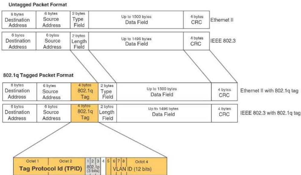
If you configure a VLAN that spans multiple devices, you need to use tagging only if a port connecting one of the devices to the other is a member of more than one port-based VLAN. If a port connecting one device to the other is a member of only a single port-based VLAN, tagging is not required.
If you use tagging on multiple devices, each device must be configured for tagging and must use the same tag value. In addition, the implementation of tagging must be compatible on the devices. The tagging on all devices is compatible with other Brocade devices.
Figure 22 shows an example of two devices that have the same Layer 2 port-based VLANs configured across them. Notice that only one of the VLANs requires tagging.
FIGURE 22 VLANs configured across multiple devices

flowchart
graph LR
    A["User-configured port-based VLAN"] --> B["T = 802.1Q tagged port"]
    B --> C["Segment 1"]
    B --> D["Segment 2"]
Segment 1
Tagging is required for the ports on Segment 1 because the ports are in multiple port-based VLANs.
Without tagging, a device receiving VLAN traffic from the other device would not be sure which VLAN the traffic is for.
Segment 2
Tagging is not required for the ports on Segment 2 because each port is in only one port-based VLAN.
Protocol-based VLANs
Interfaces that belong to a port-based VLAN can further be divided into Layer 3 broadcast domains using protocol-based VLANs. Protocol-based VLANs accept broadcasts of a specified protocol type. For example, an IP subnet VLAN accepts only broadcasts for the specified IP subnets. This feature enables you to limit the amount of broadcast traffic to end-stations, servers, and routers.
In a device, you can configure the following protocol-based VLANs within a port-based VLAN:
- AppleTalk - The device sends AppleTalk broadcasts to all ports within the AppleTalk protocol VLAN
• IP - The device sends IP broadcasts to all ports within the IP protocol VLAN
• IPX - The device sends IPX broadcasts to all ports within the IPX protocol VLAN
• IPv6 - The device sends IPv6 broadcasts to all ports within the IPv6 protocol VLAN
NOTE
You can configure a protocol-based VLAN as a broadcast domain for IPv6 traffic. When the device receives an IPv6 multicast packet (a packet with 06 in the version field and 0xFF as the beginning of the destination address), the device forwards the packet to all other ports in the VLAN except to the port that received the packet.
Protocol-based VLANs can be configured to have static or excluded port memberships. Static ports are permanent members of a protocol-based VLAN. They remain active members of the protocol-based VLAN regardless of whether they receive traffic for the VLAN's protocol.
NOTE
The dynamic port membership is not support on the BigIron RX.
If there are ports in a port-based VLAN that you want to exclude from protocol-based VLANs, the protocol-based VLAN can be configured to explicitly exclude those ports.
VLAN configuration rules
To create any type of VLAN on a device, Layer 2 forwarding must be enabled. When Layer 2 forwarding is enabled, the device becomes a switch on all ports for all non-routable protocols.
The BigIron RX can only support up to 254 independent VLAN with Layer 2 protocols.
In addition to this rule, the sections below summarize the rules for configuring VLANs.
VLAN ID range
VLAN IDs can be one of the following: 1 - 4089. IDs 4090 - 4094 are reserved for control purposes.
Tagged VLANs
When configuring VLANs across multiple devices, you need to use tagging only if a port connecting one of the devices to the other is a member of more than one port-based VLAN. If you are configuring tagged VLANs across multiple devices, make sure all the devices support the same tag format.
VLAN hierarchy
A hierarchy of VLANs exists between the Layer 2 and Layer 3 protocol-based VLANs:
- Port-based VLANs are at the lowest level of the hierarchy.
- Layer 3 protocol-based VLANs are at the highest level of the hierarchy.
As a device receives packets, the VLAN classification starts from the highest level VLAN first. Therefore, if an interface is configured as a member of a port-based VLAN and a protocol-based VLAN, packets coming into the interface are classified as members of the protocol-based VLAN because that VLAN is higher in the VLAN hierarchy.
When a port in a VLAN receives a packet, the device forwards the packet based on the following VLAN hierarchy:
- If it is a Layer 3 packet and the port is a member of a Layer 3 protocol-based VLAN for the packet's protocol, the device forwards the packet on all the Layer 3 protocol-based VLAN ports that have been configured or drops the packet if the port is explicitly excluded from the protocol VLAN.
- If the packet cannot be forwarded based on its VLAN membership types but the packet can be forwarded at Layer 2, the device forwards the packet on all the ports within the receiving port's port-based VLAN.
Multiple VLAN membership rules
Given below are the membership rules for multiple VLAN:
- A port can belong to multiple, overlapping Layer 2 port-based VLANs only if the port is a tagged port. Packets sent out of a tagged port use an 802.1q-tagged frame.
- A port can belong to multiple, unique, overlapping Layer 3 protocol-based VLANs.
- When both port and protocol-based VLANs are configured on a given device, all protocol-based VLANs must be strictly contained within a port-based VLAN. A protocol-based VLAN cannot include ports from multiple port-based VLANs. This rule is required to ensure that port-based VLANs remain loop-free Layer 2 broadcast domains.
- One of each type of protocol-based VLAN can be configured within each port-based VLAN on the device.
- Removing a configured port-based VLAN from a device automatically removes any protocol-based VLAN, or any virtual routing interfaces defined within the port-based VLAN.
Layer 2 control protocols on VLANs
Layer 2 protocols such as STP, RSTP, MRP, and VSRP can be enabled on a port-based VLANs, but you cannot enable or disable these protocols for protocol-based VLANs.
The Layer 2 state associated with a VLAN and port is determined by the Layer 2 control protocol. Layer 2 broadcasts associated with the VLAN will not be forwarded on this port if the Layer 2 state is not FORWARDING.
It is possible that the control protocol, for example STP, will block one or more ports in a protocol-based VLAN that uses a virtual routing interface to route to other VLANs. For IP protocol and IP subnet VLANs, even though some of the physical ports of the virtual routing interface are blocked, the virtual routing interface can still route as long as at least one port in the virtual routing interface's protocol-based VLAN is not blocked by STP.
You can also enable Single STP (SSTP) on the device; however, the ports in all VLANs on which SSTP is enabled become members of a single spanning tree. The ports in VLANs on which SSTP is disabled are excluded from the single spanning tree. A VLAN can also be selectively added or removed from the single spanning tree domain.
Configuring port-based VLANs
As explained above, you can place ports into VLANs to segment traffic into broadcast domains. When you create a VLAN, you specify if ports added to that VLAN are tagged or untagged.
To create a VLAN, do the following.
- At the global CONFIG level assign an ID to the VLAN. For example,
BigIron RX(config)# vlan 2
Syntax: [no] vlan-id [name
VLAN IDs can be in the range of 1 - 4089; however, do not use VLANs 4090 - 4094. These IDs are reserved and are used for control purposes. Also, VLAN IDs 0 and 4095 are reserved by the IEEE standards and cannot be configured. Use the no form of the command to delete the VLAN from the configuration.
In addition to a VLAN number, you can assign a name to a VLAN by entering name
- Once an ID is assigned, the CLI directs you to the VLAN configuration level. At this level, you add ports to that VLAN and specify if the ports are tagged or untagged.
BigIron RX(config-vlan-2)# untag e 1/9 to 1/16 BigIron RX(config-vlan-2)# tagged e 1/1 to 1/8
The example above configures a port-based VLAN, VLAN 2. It adds Ethernet ports 1/9 through 1/16 as untagged ports and ports 1/1 through 1/8 as tagged ports. Since ports 1/9 through 1/16 are untagged, they can be members of VLAN 2 only, while ports 1/1 through 1/8 are tagged ports and can be members of other VLANs.
NOTE
In the configuration above, ports 1/9 - 1/16 are explicitly removed from the default VLAN since they are configured as untagged ports; while port 1/1 - 1/8 are still members of the default VLAN.
Syntax: [no] untagged | tagged ethernet
The untagged and tagged parameter removes ports from the default VLAN and puts them in the port-based VLAN. The untag command also allows the ports to process packets that do not contain 802.1q tagging.
The tagged parameter allows the device to add a four-byte tag 802.1q tag to the packets that go through the tagged ports. It also allows the ports to be members of other VLANs.
Enter the port that you want to assign to the VLAN for the ethernet
Use the no form of the command to remove the ports from a VLAN. For example.
BigIron RX(config)# vlan 4 BigIron RX(config-vlan-4)# no untag ethernet 1/11
VLAN byte accounting
To enable your device to perform accounting of the number of bytes received by all the member ports of a VLAN. This includes the preamble and the minimum inter-frame gap in Ethernet. The byte counts can then be viewed using the show vlan command. VLAN byte accounting is disabled by default.
Considerations when configuring VLAN byte accounting
- VLAN byte accounting cannot be enabled for the default or control VLANs.
- The number of VLANs on which byte accounting can be enabled system-wide is restricted by the number of VLANs with byte accounting enabled on a given packet processor and the number of rate limiting policies enabled on the same packet processor ports. Refer to Table 64 for details.
-
On a given packet processor, the total number of VLANs with byte accounting enabled and the number of ACL-based and VLAN-based rate limiting policies is dependent on the interface module. Refer to Table 64 for details.
-
If a port's VLAN has byte accounting enabled, you cannot enable rate limiting on that port. Similarly, if a port has rate limiting enabled, you cannot enable VLAN byte accounting on that port's VLAN.
- Clearing the rate limiting counters using clear rate-limit counters will also clear VLAN byte-accounting counters. It is recommended that when using rate limiting along with VLAN byte accounting, use individual port rate limiting counters.
Configuring VLAN byte accounting
To enable VLAN accounting on a specified VLAN, use the following commands.
BigIron RX(config)# vlan 10
BigIron RX(config-vlan-10)# byte-accounting
Syntax: [no] byte-accounting
Displaying VLAN byte accounting information
To display VLAN accounting information for all VLANs configured on a router, use the show vlan command as shown.
BigIron RX# show vlan
Configured PORT-VLAN entries: 2
Maximum PORT-VLAN entries: 512
Default PORT-VLAN id: 1
PORT-VLAN 1, Name DEFAULT-VLAN, Priority Level0
L2 protocols : NONE
Untagged Ports : ethe 1/1 to 1/40 ethe 2/1 to 2/4
PORT-VLAN 10, Name [None], Priority Level0
L2 protocols : NONE
Tagged Ports : ethe 1/2 to 1/5
Bytes received : 18527
To display VLAN accounting information for a specific VLAN, use the show vlan
BigIron RX# show vlan 10
PORT-VLAN 10, Name [None], Priority Level0
L2 protocols : NONE
Tagged Ports : ethe 1/2 to 1/5
Bytes received : 5626
The Bytes received field displays the number of bytes received by all member ports of all VLANs configured on the router.
Maximum number of rate limiting policies and VLANs with byte accounting
The maximum number of ACL-based, and VLAN-based rate limiting policies that can be configured on ports controlled by the same packet processor also depends on the number of VLANs with byte accounting enabled on the same packet processor.
On a given packet processor (PPCR), the total of:
Number of VLANs with byte accounting enabled
+
Number of rate limiting policies based on ACLs and VLANs cannot exceed the maximum number of policies as specified in Table 64.
TABLE 64 Maximum # of rate limiting policies and VLANs w/ byte accounting permitted per-PPCR
| Module type | PPCR number | Port # | Max # of rate limiting policies based on ACLs and VLANs + number of VLANs w/ byte accounting enabled |
| 24 x 1G PPCR 1 1 - 12 115 | |||
| PPCR 2 13 - 24 115 | |||
Clearing counters
To clear the byte counter for a VLAN, enter a command such as the following:
BigIron RX(config) #clear vlan byte-accounting 10
You can also enter the following command to clear the byte counter for all VLANs
BigIron RX(config) #clear vlan byte-accounting all-vlans
Syntax: clear vlan byte-accounting
Enter a VLAN ID if you want to clear the byte counters for a specific VLAN. Enter all-vlans to clear the byte counters for all VLANs.
Strictly or explicitly tagging a port
If you want a port to be strictly or explicitly tagged, that port has to be removed from the default VLAN. Enter a command such as the following.
BigIron RX(config)# vlan 2
BigIron RX(config-vlan-2)# tagged e 1/1 to 1/8
BigIron RX(config-vlan-2)# vlan 1
BigIron RX(config-vlan-1)# no untagged e 1/1 to 1/8
Assigning or changing a VLAN priority
You can prioritize traffic on a VLAN by assigning a priority to a VLAN. All packets associated with the VLAN will be classified to the configured priority.
BigIron RX(config-vlan-2)# priority 2
Syntax: [no] priority
Possible Values: 0 - 7, "0" assigns the lowest priority and "7", the highest priority. The default is "0".
Assigning a different ID to the default VLAN
As stated above, by default, all ports on a device belong to the default VLAN, which is VLAN 1, until it is assigned to a port-based VLAN. The default VLAN port membership is always untagged; however, if you want to use VLAN ID 1 as a configurable VLANs with tagged port members, you can assign a different VLAN ID as the default VLAN. Enter commands such as the following command.
BigIron RX(config)# default-vlan-id 4000
Syntax: [no] default-vlan-id
You must specify a VLAN ID that is not already in use. For example, if VLAN 10 exists, do not use "10" as the new VLAN ID for the default VLAN. Valid VLAN IDs are from 1 - 4089; however, do not use VLANs 4090 - 4094, which are reserved for control purposes.
Configuring protocol-based VLANs
Once port-based VLANs are created, you can further segment the broadcast domains by creating protocol-based VLANs, based on Layer 3 protocols. Use the general procedure below for creating protocol-based VLANs.
- Create the port-based VLAN that contains the interface that you want to segment using Layer 3 protocols.
BigIron RX(config)# vlan 2
BigIron RX(config-vlan-2)# untag e 1/9 to 1/16
BigIron RX(config-vlan-2)# tagged e 1/1 to 1/8
- Under the VLAN configuration level, define the Layer 3 protocol you want to use to segment packets that go through the ports assigned to the port-based VLAN.
BigIron RX(config-vlan-2)# ipv6-proto name Blue
Syntax: [no] ip-proto | ipv6-proto | ipx-proto | atalk-proto | other-proto name
Enter:
- ip-proto to create a IP protocol VLAN.
- ipv6-proto to create a IPv6 protocol VLAN.
- ipx-proto to create a IPX protocol VLAN.
- atalk-proto to create an Appletalk protocol VLAN.
- other-proto to create a protocol VLAN for protocols other than an IP protocol, IPv6, IPX, or Appletalk protocol.
Enter name
Use the no form of the command to remove the protocol-based VLAN.
- Assign or exclude specific ports to the protocol-based VLAN
BigIron RX(config-vlan-group-ipv6-proto)# static e 1/1 e 1/24
BigIron RX(config-vlan-group-ipv6-proto)# exclude e 1/2 to 1/4
Syntax: [no] static | exclude ethernet
The static ethernet
The exclude ethernet
Configuring an MSTP instance
An MSTP instance is configured with an MSTP ID for each region. Each region can contain one or more VLANs. To configure an MSTP instance and assign a range of VLANs, use a command such as the following at the Global Configuration level.
BigIron RX(config) # mstp instance 7 vlan 4 to 7
Syntax: [no] mstp instance
The instance parameter defines the number for the instance of MSTP that you are configuring.
The vlan parameter assigns one or more VLANs or a range of VLANs to the instance defined in this command.
The vlan-group parameter assigns one or more VLAN groups to the instance defined in this command.
Configuring virtual routing interfaces
The device sends Layer 3 traffic at Layer 2 within a protocol-based VLAN. However, Layer 3 traffic from one protocol-based VLAN to another must be routed. If you want the device to be able to send Layer 3 traffic from one protocol-based VLAN to another on the same router, you must configure a virtual routing interface on each protocol-based VLAN, then configure routing parameters on the virtual routing interfaces.
A virtual routing interface is a logical routing interface that the device uses to route Layer 3 protocol traffic between protocol-based VLANs. It is a logical port on which you can configure Layer 3 routing parameters.
For example, to enable a device to route IP traffic from one IP protocol VLAN to another, you must configure a virtual routing interface on each IP protocol VLAN, then configure the appropriate IP routing parameters on each of the virtual routing interfaces.
For example,
BigIron RX(config)# vlan 2
BigIron RX(config-vlan-2)# tagged e 1/1 to 1/2
BigIron RX(config-vlan-2)# ip-proto
BigIron RX(config-vlan-group-ip-proto)# router-interface ve 1
The device can locally route IP packets between VLANs that are defined within a single router. All other routable protocols or protocol-based VLANs (for example, IPX and AppleTalk) must be routed by another external router capable of routing the protocol.
If you do not need to further partition the port-based VLAN into protocol-based VLANs, you can define a single virtual routing interface at the port-based VLAN level and enable routing on a single virtual routing interface.
BigIron RX(config)# vlan 2
BigIron RX(config-vlan-2)# tagged e 1/1 to 1/2
BigIron RX(config-vlan-2)# router-interface ve 2
BigIron RX(config-vlan-2)# exit
BigIron RX(config)# interface ve 2
BigIron RX(config-ve-2)# ip address 10.1.1.1/24
Syntax: router-interface ve
Enter 1 to the maximum number of virtual routing interfaces supported on the device for
Bridging and routing the same protocol simultaneously on the same device
Some configurations may require simultaneous switching and routing of the same single protocol across different sets of ports on the same router. When IP routing is enabled on a device, you can route IP packets on specific interfaces while bridging them on other interfaces. In this scenario, you can create two separate backbones for the same protocol, one bridged and one routed.
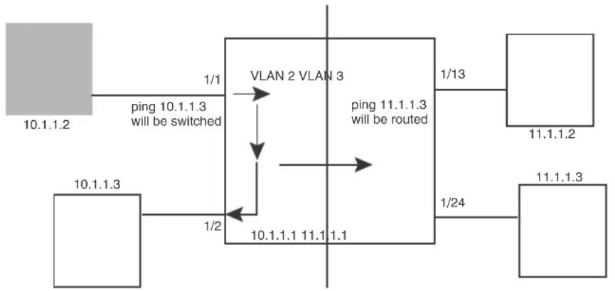
flowchart
graph TD
    A["10.1.1.2"] -->|ping 10.1.1.3 will be switched| B["VLAN 2 VLAN 3"]
    C["10.1.1.3"] -->|1/2| B
    D["11.1.1.2"] -->|1/13| E["ping 11.1.1.3 will be routed"]
    F["11.1.1.3"] -->|1/24| E
    B -->|10.1.1.1 11.1 1.1| B
The following is a sample configuration for the illustration above.
BigIron RX(config)# vlan 2
BigIron RX(config-vlan-2)# tagged e 1/1 to 1/2
BigIron RX(config-vlan-2)# router-inter ve 2
BigIron RX(config-vlan-2)# ip-proto static e 1/1/ to 1/2
BigIron RX(config-vlan-2)# exit
BigIron RX(config)# vlan 3
BigIron RX(config-vlan-3)# tagged e 1/13 to 1/24
BigIron RX(config-vlan-3)# router-int ve 3
BigIron RX(config-vlan-3)# exit
BigIron RX(config)# interface ve 2
BigIron RX(config-ve-2)# ip address 10.1.1.1/24
BigIron RX(config-if-e1000-2/1)# exit
BigIron RX(config)# interface ve 3
BigIron RX(config-ve-3)# ip address 11.1.1.2/24
IP packets are bridged (switched) within the same protocol VLAN if they are on the same subnet; they are routed if they are on a different VLAN.
Integrated Switch Routing (ISR)
Brocade Integrated Switch Routing (ISR) feature enables VLANs configured on the device to route Layer 3 traffic from one protocol-based VLAN to another instead of forwarding the traffic to an external router. The VLANs provide Layer 3 broadcast domains for the protocols, but do not in themselves provide routing services. This is true even if the source and destination protocols are on the same device.
ISR eliminates the need for an external router by allowing you to route between VLANs using virtual routing interfaces (ves). You configure a separate virtual routing interface on each VLAN that you want to use to route packets. For example, if you configure two IP protocol VLANs on a device, you can configure a virtual routing interface on each of the IP protocol VLAN, then configure IP routing parameters for the IP protocol VLAN. Thus, the device forwards IP broadcasts within each VLAN at Layer 2 but routes Layer 3 traffic between the VLANs using the virtual routing interfaces.
NOTE
The device uses the lowest MAC address on the device (the MAC address of port 1/1) as the MAC address for all ports within all virtual routing interfaces you configure on the device.
The routing parameters and the syntax for configuring them are the same as when you configure a physical interface for routing (for example, interface ve 10). The logical interface allows the device to internally route traffic between the protocol-based VLANs without using physical interfaces.
All the ports within a protocol-based VLAN must be in the same port-based VLAN. The protocol-based VLAN cannot have ports in multiple port-based VLANs, unless the ports in the port-based VLAN to which you add the protocol-based VLAN are 802.1q tagged.
You can configure multiple protocol-based VLANs within the same port-based VLAN. In addition, a port within a port-based VLAN can belong to multiple protocol-based VLANs of the same type or different types. For example, if you have a port-based VLAN that contains ports 1/1 - 1/10, you can configure port 1/5 as a member of an AppleTalk protocol VLAN, an IP protocol VLAN, and an IPX protocol VLAN, and so on.
If the router interface for IP is configured on physical ports, then routing occurs independent of the Spanning Tree Protocol (STP). However, if the router interfaces are defined for IP VLAN, they are virtual routing interfaces and are subject to the rules of STP.
If your backbone is consisted of virtual routing interfaces all within the same STP domain, it is a bridged backbone, not a routed one. This means that the set of backbone interfaces that are blocked by STP will be blocked for routed protocols as well. The routed protocols will be able to cross these paths only when the STP state of the link is FORWARDING. This problem is easily avoided by proper network design.
When designing an ISR network, pay attention to your use of virtual routing interfaces and the spanning-tree domain. If Layer 2 switching of your routed protocols (IP, IPX, AppleTalk) is not required across the backbone, then the use of virtual routing interfaces can be limited to edge switch ports within each router. Full backbone routing can be achieved by configuring routing on each physical interface that connects to the backbone. Routing is independent of STP when configured on a physical interface.
If your ISR design requires that you switch IP, IPX, or Appletalk at Layer 2 while simultaneously routing the IP protocol over a single backbone, then create multiple port-based VLANs and use VLAN tagging on the backbone links to separate your Layer 2 switched and Layer 3 routed networks.
There is a separate STP domain for each port-based VLAN. Routing occurs independently across port-based VLANs or STP domains. You can define each end of each backbone link as a separate tagged port-based VLAN. Routing will occur independently across the port-based VLANs. Because each port-based VLAN's STP domain is a single point-to-point backbone connection, you are guaranteed to never have an STP loop. STP will never block the virtual router interfaces within the tagged port-based VLAN, and you will have a fully routed backbone.
A device offers the ability to create a virtual routing interface within a Layer 2 STP port-based VLAN or within each IP protocol VLAN. This combination of multiple Layer 2 or Layer 3 broadcast domains and virtual routing interfaces are the basis for Brocade' very powerful Integrated Switch Routing (ISR) technology. ISR is very flexible and can solve many networking problems.
VLAN groups
To simplify VLAN configuration when you have many VLANs with the same configuration, you can configure VLAN groups. When you create a VLAN group, the VLAN parameters you configure for the group apply to all the VLANs within the group.
The VLAN group feature allows you to create multiple port-based VLANs with identical port members. Since the member ports are shared by all the VLANs within the group, you must add the ports as tagged ports. This feature not only simplifies VLAN configuration but also allows you to have a large number of identically configured VLANs in a startup configuration file on the device's flash memory module. Normally, a startup configuration file with a large number of VLANs might not fit on the flash memory module. By grouping the identically configured VLANs, you can conserve space in the startup configuration file so that it fits on the flash memory module.
You can create up to 32 VLAN groups
NOTE
Depending on the size of the VLAN ID range you want to use for the VLAN group, you might need to allocate additional memory for VLANs. To allocate additional memory, refer to "Allocating memory for more VLANs or virtual routing interfaces" on page 319.
Configuring a VLAN group
To configure a VLAN group, do the following.
- Create the VLAN group and assign the VLANs to that group.
BigIron RX(config)# vlan-group 1 vlan 2 to 1000
Syntax: [no] vlan-group
Use 1 - 32 for
The vlan
If a VLAN within the range you specify is already configured, the CLI does not add the group but instead displays an error message. If this happens, create the group by specifying a valid contiguous range that does not include the VLAN. Then add more VLANs to the group after the CLI changes to the configuration level for the group.
NOTE
The device's memory must be configured to contain at least the number of VLANs you specify for the higher end of the range. For example, if you specify 2048 as the VLAN ID at the high end of the range, you first must increase the memory allocation for VLANs to 2048 or higher. Refer to "Allocating memory for more VLANs or virtual routing interfaces" on page 319.
- The CLI directs you to the VLAN group configuration level. Add tagged ports to the group. Since all the VLANs in the group share the ports, you must add the ports as tagged ports.
BigIron RX(config-vlan-group-1)# tagged e 1/1 to 1/2
Syntax: [no] tagged ethernet [to
- If required, you can add and remove individual VLANs or VLAN ranges from the VLAN group configuration level. For example, to add VLANs 1001 and 1002 to VLAN group 1 and remove VLANs 900 through 1000, enter the following commands.
BigIron RX(config-vlan-group-1)# add-vlan 1001 to 1002
BigIron RX(config-vlan-group-1)# remove-vlan 900 to 1000
Syntax: [no] add-vlan
Syntax: remove-vlan
Verifying VLAN group configuration
To verify configuration of VLAN groups, display the running configuration file. If you have saved the configuration to the startup configuration file, you also can verify the configuration by displaying the startup configuration file. The following example shows the running configuration information for the VLAN group configured in the previous examples. The information appears in the same way in the startup configuration file.
BigIron RX(config)# show running-config
lines not related to the VLAN group omitted...
vlan-group 1 vlan 2 to 900
add-vlan 1001 to 1002
tagged ethe 1/1 to 1/2
Displaying information about VLAN groups
To display VLAN group configuration information, enter the following command.
BigIron RX# show vlan-group 10
Configured VLAN-Group entries : 1
Maximum VLAN-Group entries : 32
VLAN-GROUP 10
Number of VLANs: 4
VLANs: 10 to 13
Tagged ports: ethe 3/1
The example shows configuration information for two VLAN groups, group 1 and group 2.
Syntax: show vlan-group [
The
Configuring super aggregated VLANs
A super aggregated VLAN allows multiple VLANs to be placed within another VLAN. This feature allows you to construct Layer 2 paths and channels. A path contains multiple channels, each of which is a dedicated circuit between two end points. The two devices at the end points of the channel appear to each other to be directly attached. The network that connects them is transparent to the two devices.
You can aggregate up to 4089 VLANs within another VLAN. This provides a total VLAN capacity on one device of 16,760,836 channels (4089 * 4089).
The devices connected through the channel are not visible to devices in other channels. Therefore, each client has a private link to the other side of the channel.
Super aggregated VLANs are useful for applications such as Virtual Private Network (VPN) in which you need to provide a private, dedicated Ethernet connection to individual clients to transparently reach its subnet across multiple networks. The feature allows point-to-point and point-to-multipoint connections.
Figure 23 shows a conceptual picture of the service that aggregated VLANs provide.
FIGURE 23 Conceptual model of the super aggregated VLAN application

flowchart
graph TD
    A["Client 1\n192.168.1.69/24"] --> B["Client 3"]
    B --> C["Client 5"]
    D["sub-net\n192.168.1.0/24"] --> E["Subnet"]
    F["Path = a single VLAN into which client VLANs are aggregated"] -.-> B
    G["Channel = a client VLAN nested inside a Path"] -.-> C
Each client connected to the edge device is in its own port-based VLAN. All the clients' VLANs are aggregated by the edge device into a single VLAN for connection to the core.
The device that aggregates the VLANs forwards the aggregated VLAN traffic through the core. The core can consist of multiple devices that forward the aggregated VLAN traffic. The edge device at the other end of the core separates the aggregated VLANs into the individual client VLANs before forwarding the traffic. The edge devices forward the individual client traffic to the clients. For the clients' perspective, the channel is a direct point-to-point link.
Figure 24 shows an example application that uses aggregated VLANs. This configuration includes the client connections shown in Figure 23.
FIGURE 24 Example super aggregated VLAN application

flowchart
graph TD
    Client1["Client 1\nPort1/1\nVLAN 101"] -->|209.157.2.12/24| DeviceA["Device A Tag Type 8100"]
    Client3["Client 3\nPort1/3\nVLAN 103"] -->|209.157.2.12/24| DeviceA
    Client5["Client 5\nPort1/5\nVLAN 105"] -->|209.157.2.12/24| DeviceB["Device B Tag Type 8100"]
    Client6["Client 6\nPort1/1\nVLAN 101"] -->|209.157.2.12/24| DeviceB
    Client8["Client 8\nPort1/3\nVLAN 103"] -->|209.157.2.12/24| DeviceB
    Client10["Client 10\nPort1/5\nVLAN 105"] -->|209.157.2.12/24| DeviceB
    Client1["Client 1\nPort1/1\nVLAN 101"] -->|209.157.2.12/24| DeviceC["Device C Tag Type 9100\nVLAN Aggregation Enabled"]
    Client3["Client 3\nPort1/3\nVLAN 103"] -->|209.157.2.12/24| DeviceC
    Client5["Client 5\nPort1/5\nVLAN 105"] -->|209.157.2.12/24| DeviceC
    Client6["Client 6\nPort1/1\nVLAN 101"] -->|209.157.2.12/24| DeviceB
    Client8["Client 8\nPort1/3\nVLAN 103"] -->|209.157.2.12/24| DeviceB
    Client10["Client 10\nPort1/5\nVLAN105"] -->|209.157.2.12/24| DeviceB
    DeviceA -->|Port2/1 Tagged| DeviceC
    DeviceA -->|Port3/1 Untagged| DeviceD
    DeviceA -->|Port4/1 Tagged| DeviceD
    DeviceA -->|Port3/2 Untagged| DeviceE
    DeviceB -->|Port2/1 Tagged| DeviceE
    DeviceB -->|Port4/1 Tagged| DeviceD
    DeviceB -->|Port3/2 Untagged| DeviceE
    DeviceE -->|Port2/1 Tagged| DeviceF
    DeviceE -->|Port3/1 Untagged| DeviceF
    DeviceE -->|Port4/1 Tagged| DeviceE
    DeviceE -->|Port3/2 Untagged| DeviceF
Figure 22 shows a collocation service providing private channels for multiple clients. Although the same devices are used for all the clients, the VLANs ensure that each client receives its own Layer 2 broadcast domain, separate from the broadcast domains of other clients. For example, client 1 cannot ping client 5.
The clients at each end of a channel appear to each other to be directly connected and thus can be on the same subnet and use network services that require connection to the same subnet. In this example, client 1 is in subnet 192.168.1.0/24 and so is the device at the other end of client 1's channel.
Since each VLAN configured on the core devices is an aggregate of multiple client VLANs, the aggregated VLANs greatly increase the number of clients a core device can accommodate.
This example shows a single link between the core devices. However, you can use a trunk group to add link-level redundancy.
Configuring aggregated VLANs
A maximum of 1526 bytes are supported on ports where super-aggregated VLANs are configured. This allows for an additional 8 bytes over the untagged port maximum to allow for support of two VLAN tags.
To configure aggregated VLANs, configure tagged and untagged VLANs on the edge device, then configure the aggregated and other VLANs on the core device. Perform the following tasks.
-
On each edge device, configure a separate port-based VLAN for each client connected to the edge device. In each client VLAN:
-
Add the port connected to the client as an untagged port.
- Add the port connected to the core device (the device that will aggregate the VLANs) as a tagged port. This port must be tagged because all the client VLANs share the port as an uplink to the core device.
For example, to configure device A in Figure 24 on page 302, enter commands such as the following.
BigIron RX(config)# vlan 101
BigIron RX(config-vlan-101)# tagged ethernet 2/1
BigIron RX(config-vlan-101)# untagged ethernet 1/1
BigIron RX(config-vlan-101)# exit
BigIron RX(config)# vlan 102
BigIron RX(config-vlan-102)# tagged ethernet 2/1
BigIron RX(config-vlan-102)# untagged ethernet 1/2
BigIron RX(config-vlan-102)# exit
BigIron RX(config)# vlan 103
BigIron RX(config-vlan-103)# tagged ethernet 2/1
BigIron RX(config-vlan-103)# untagged ethernet 1/3
BigIron RX(config-vlan-103)# exit
BigIron RX(config)# vlan 104
BigIron RX(config-vlan-104)# tagged ethernet 2/1
BigIron RX(config-vlan-104)# untagged ethernet 1/4
BigIron RX(config-vlan-104)# exit
BigIron RX(config)# vlan 105
BigIron RX(config-vlan-105)# tagged ethernet 2/1
BigIron RX(config-vlan-105)# untagged ethernet 1/5
BigIron RX(config-vlan-105)# exit
BigIron RX(config)# write memory
Syntax: [no] vlan
Syntax: [no] untagged | tagged ethernet
The tagged command adds the port that the device uses for the uplink to the core device.
The untagged command adds the ports connected to the individual clients.
- On each core device:
- Enable VLAN aggregation. This support allows the core device to add an additional tag to each Ethernet frame that contains a VLAN packet from the edge device. The additional tag identifies the aggregate VLAN (the path). However, the additional tag can cause the frame to be longer than the maximum supported frame size. The larger frame support allows Ethernet frames up to 1530 bytes long.
NOTE
Enable the VLAN aggregation option only on the core devices.
- Configure a VLAN tag type (tag ID) that is different than the tag type used on the edge devices. If you use the default tag type (8100) on the edge devices, set the tag type on the core devices to another value, such as 9100. The tag type must be the same on all the core devices. The edge devices also must have the same tag type but the type must be different from the tag type on the core devices.
NOTE
You can enable the Spanning Tree Protocol (STP) on the edge devices or the core devices, but not both. If you enable STP on the edge devices and the core devices, STP will prevent client traffic from travelling through the core to the other side.
For example, to configure the aggregated VLANs on device C in Figure 24 on page 302, enter the following commands.
BigIron RX(config)# tag-type 9100
BigIron RX(config)# aggregated-vlan
BigIron RX(config)# vlan 101
BigIron RX(config-vlan-101)# tagged ethernet 4/1
BigIron RX(config-vlan-101)# untagged ethernet 3/1
BigIron RX(config-vlan-101)# exit
BigIron RX(config)# vlan 102
BigIron RX(config-vlan-102)# tagged ethernet 4/1
BigIron RX(config-vlan-102)# untagged ethernet 3/2
BigIron RX(config-vlan-102)# exit
BigIron RX(config)# write memory
Syntax: [no] tag-type
Syntax: [no] aggregated-vlan
The
Complete CLI examples
The following sections show all the Aggregated VLAN configuration commands on the devices in Figure 24 on page 302.
NOTE
In these examples, the configurations of the edge devices (A, B, E, and F) are identical. The configurations of the core devices (C and D) also are identical. The aggregated VLAN configurations of the edge and core devices on one side must be symmetrical (in fact, a mirror image) to the configurations of the devices on the other side. For simplicity, the example in Figure 24 on page 302 is symmetrical in terms of the port numbers. This allows the configurations for both sides of the link to be the same. If your configuration does not use symmetrically arranged port numbers, the configurations should not be identical but must use the correct port numbers.
Commands for device A
BigIron RX-A(config)# vlan 101
BigIron RX-A(config-vlan-101)# tagged ethernet 2/1
BigIron RX-A(config-vlan-101)# untagged ethernet 1/1
BigIron RX-A(config-vlan-101)# exit
BigIron RX-A(config)# vlan 102
BigIron RX-A(config-vlan-102)# tagged ethernet 2/1
BigIron RX-A(config-vlan-102)# untagged ethernet 1/2
BigIron RX-A(config-vlan-102)# exit
BigIron RX-A(config)# vlan 103
BigIron RX-A(config-vlan-103)# tagged ethernet 2/1
BigIron RX-A(config-vlan-103)# untagged ethernet 1/3
BigIron RX-A(config-vlan-103)# exit
BigIron RX-A(config)# vlan 104
BigIron RX-A(config-vlan-104)# tagged ethernet 2/1
BigIron RX-A(config-vlan-104)# untagged ethernet 1/4
BigIron RX-A(config-vlan-104)# exit
BigIron RX-A(config)# vlan 105
BigIron RX-A(config-vlan-105)# tagged ethernet 2/1
BigIron RX-A(config-vlan-105)# untagged ethernet 1/5
BigIron RX-A(config-vlan-105)# exit
BigIron RX-A(config)# write memory
Commands for device B
The commands for configuring device B are identical to the commands for configuring device A. Notice that you can use the same channel VLAN numbers on each device. The devices that aggregate the VLANs into a path can distinguish between the identically named channel VLANs based on the ID of the path VLAN.
BigIron RX-B(config)# vlan 101
BigIron RX-B(config-vlan-101)# tagged ethernet 2/1
BigIron RX-B(config-vlan-101)# untagged ethernet 1/1
BigIron RX-B(config-vlan-101)# exit
BigIron RX-B(config)# vlan 102
BigIron RX-B(config-vlan-102)# tagged ethernet 2/1
BigIron RX-B(config-vlan-102)# untagged ethernet 1/2
BigIron RX-B(config-vlan-102)# exit
BigIron RX-B(config)# vlan 103
BigIron RX-B(config-vlan-103)# tagged ethernet 2/1
BigIron RX-B(config-vlan-103)# untagged ethernet 1/3
BigIron RX-B(config-vlan-103)# exit
BigIron RX-B(config)# vlan 104
BigIron RX-B(config-vlan-104)# tagged ethernet 2/1
BigIron RX-B(config-vlan-104)# untagged ethernet 1/4
BigIron RX-B(config-vlan-104)# exit
BigIron RX-B(config)# vlan 105
BigIron RX-B(config-vlan-105)# tagged ethernet 2/1
BigIron RX-B(config-vlan-105)# untagged ethernet 1/5
BigIron RX-B(config-vlan-105)# exit
BigIron RX-B(config)# write memory
Commands for device C
Since device C is aggregating channel VLANs from devices A and B into a single path, you need to change the tag type and enable VLAN aggregation.
BigIron RX-C(config)# tag-type 9100
BigIron RX-C(config)# aggregated-vlan
BigIron RX-C(config)# vlan 101
BigIron RX-C(config-vlan-101)# tagged ethernet 4/1
BigIron RX-C(config-vlan-101)# untagged ethernet 3/1
BigIron RX-C(config-vlan-101)# exit
BigIron RX-C(config)# vlan 102
BigIron RX-C(config-vlan-102)# tagged ethernet 4/1
BigIron RX-C(config-vlan-102)# untagged ethernet 3/2
BigIron RX-C(config-vlan-102)# exit
BigIron RX-C(config)# write memory
Commands for device D
Device D is at the other end of path and separates the channels back into individual VLANs. The tag type must be the same as tag type configured on the other core device (Device C). In addition, VLAN aggregation also must be enabled.
BigIron RX-D(config)# tag-type 9100
BigIron RX-D(config)# aggregated-vlan
BigIron RX-D(config)# vlan 101
BigIron RX-D(config-vlan-101)# tagged ethernet 4/1
BigIron RX-D(config-vlan-101)# untagged ethernet 3/1
BigIron RX-D(config-vlan-101)# exit
BigIron RX-D(config)# vlan 102
BigIron RX-D(config-vlan-102)# tagged ethernet 4/1
BigIron RX-D(config-vlan-102)# untagged ethernet 3/2
BigIron RX-D(config-vlan-102)# exit
BigIron RX-D(config)# write memory
Commands for device E
Since the configuration in Figure 24 on page 302 is symmetrical, the commands for configuring device E are identical to the commands for configuring device A.
BigIron RX-E(config)# vlan 101
BigIron RX-E(config-vlan-101)# tagged ethernet 2/1
BigIron RX-E(config-vlan-101)# untagged ethernet 1/1
BigIron RX-E(config-vlan-101)# exit
BigIron RX-E(config)# vlan 102
BigIron RX-E(config-vlan-102)# tagged ethernet 2/1
BigIron RX-E(config-vlan-102)# untagged ethernet 1/2
BigIron RX-E(config-vlan-102)# exit
BigIron RX-E(config)# vlan 103
BigIron RX-E(config-vlan-103)# tagged ethernet 2/1
BigIron RX-E(config-vlan-103)# untagged ethernet 1/3
BigIron RX-E(config-vlan-103)# exit
BigIron RX-E(config)# vlan 104
BigIron RX-E(config-vlan-104)# tagged ethernet 2/1
BigIron RX-E(config-vlan-104)# untagged ethernet 1/4
BigIron RX-E(config-vlan-104)# exit
BigIron RX-E(config)# vlan 105
BigIron RX-E(config-vlan-105)# tagged ethernet 2/1
BigIron RX-E(config-vlan-105)# untagged ethernet 1/5
BigIron RX-E(config-vlan-105)# exit
BigIron RX-E(config)# write memory
Commands for device F
The commands for configuring device F are identical to the commands for configuring device E. In this example, since the port numbers on each side of the configuration in Figure 24 on page 302 are symmetrical, the configuration of device F is also identical to the configuration of device A and device B.
BigIron RX-F(config)# vlan 101
BigIron RX-F(config-vlan-101)# tagged ethernet 2/1
BigIron RX-F(config-vlan-101)# untagged ethernet 1/1
BigIron RX-F(config-vlan-101)# exit
BigIron RX-F(config)# vlan 102
BigIron RX-F(config-vlan-102)# tagged ethernet 2/1
BigIron RX-F(config-vlan-102)# untagged ethernet 1/2
BigIron RX-F(config-vlan-102)# exit
BigIron RX-F(config)# vlan 103
BigIron RX-F(config-vlan-103)# tagged ethernet 2/1
BigIron RX-F(config-vlan-103)# untagged ethernet 1/3
BigIron RX-F(config-vlan-103)# exit
BigIron RX-F(config)# vlan 104
BigIron RX-F(config-vlan-104)# tagged ethernet 2/1
BigIron RX-F(config-vlan-104)# untagged ethernet 1/4
BigIron RX-F(config-vlan-104)# exit
BigIron RX-F(config)# vlan 105
BigIron RX-F(config-vlan-105)# tagged ethernet 2/1
BigIron RX-F(config-vlan-105)# untagged ethernet 1/5
BigIron RX-F(config-vlan-105)# exit
BigIron RX-F(config)# write memory
Configuring 802.1q-in-q tagging
802.1Q-in-Q tagging enables you to configure 802.1Q tag-types on a group of ports, such as trunk ports, thereby enabling the creation of two identical 802.1Q tags (802.1Q-in-Q tagging) on a single device. This feature improves SAV interoperability between Brocade devices and other vendors' devices that support the 802.1Q tag-types, but are not very flexible with the tag-types they accept.
Figure 25 on page 307 shows an 802.1Q configuration example.
FIGURE 25 802.1Q configuration example

flowchart
graph LR
    A["To customer interface Provider"] --> B["Edge Switch"]
    B --> C["Uplink to provider cloud"]
    D["Untagged"] --> E["Tagged"]
    E --> F["End"]
| DA | SA | 8100 | Customer VLAN |
| DASA 81009100 | ProviderVLAN | CustomerVLAN | ||||
As shown in Figure 25, the ports to customer interfaces are untagged, whereas the uplink ports to the provider cloud are tagged, because multiple client VLANs share the uplink to the provider cloud. In this example, the device treats the customer's private VLAN ID and 8100 tag type as normal payload, and adds the 9100 tag type to the packet when the packet is sent to the uplink and forwarded along the provider cloud.
As long as the switches in the provider's network support the 9100 tag type, the data gets switched along the network. However, devices that do not support the 9100 tag type may not properly handle the packets.
Figure 26 shows an example application of the 802.1Q-in-Q enhancement.
FIGURE 26 802.1Q-in-Q configuration example
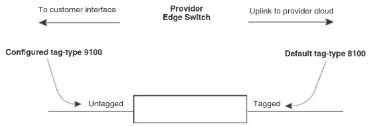
flowchart
graph LR
    A["Configuration tag-type 9100"] --> B["Untagged"]
    B --> C["Tagged"]
    D["Provider Edge Switch"] --> E["Uplink to provider cloud"]
    F["To customer interface"] --> A
    G["Default tag-type 8100"] --> H["Tagged"]
| DA | SA | 8100 | Customer VLAN |
| DA SA 8100 | 8100 | ProviderVLAN | CustomerVLAN |
In Figure 26, the untagged ports (to customer interfaces) accept frames that have any 802.1Q tag other than the configured tag-type 9100. These packets are considered untagged on this incoming port and are re-tagged when they are sent out of the uplink towards the provider. The 802.1Q tag-type on the uplink port is 8100, so the device will switch the frames to the uplink device with an additional 8100 tag, thereby supporting devices that only support this method of VLAN tagging.
Configuration rules
Follow the rules below when configuring 802.1q-in-q tagging:
- Since the uplink (to the provider cloud) and the edge link (to the customer port) must have different 802.1Q tags, make sure the uplink and edge link are in different port regions.
- If you configure a port with an 802.1Q tag-type, the device automatically applies the 802.1Q tag-type to all ports within the same port region.
- If you remove the 802.1Q tag-type from a port, the device automatically removes the 802.1Q tag-type from all ports within the same port region.
- The device supports on configured tag-type per device, along with the default tag-type of 8100. For example, if you configure an 802.1Q tag of 9100 on ports 1 - 8, then later configure an 802.1Q tag of 5100 on port 9, the device automatically applies the 5100 tag to all ports in the same port region as port 9, and also changes the 802.1Q tag-type on ports 1 - 8 to 5100.
Enabling 802.1Q-in-Q tagging
To enable the 802.1Q-in-Q feature, configure an 802.1Q tag type on the untagged edge links (the customer ports) to any value other than the 802.1Q tag for incoming traffic.
For example, in Figure 27, the 802.1Q tag on the untagged edge links (ports 11 and 12) is 9100, whereas, the 802.1Q tag for incoming traffic is 8100.
To configure 802.1 Q-in-Q tagging as shown in Figure 27, enter commands such as the following on the untagged edge links of devices C and D.
BigIron RX(config)# tag-type 9100 e3/1 to 3/2
BigIron RX(config)# aggregated-vlan
Note that since ports 11 and 12 belong to the port region 1 - 12, the 802.1Q tag actually applies to ports 1 - 12.
Syntax: [no] tag-type <num> [ethernet <slot-number>/<port-number> [to <slot-number>/<port-number>]]
The
The ethernet
- If you specify a single port number, the 802.1Q tag applies only to that port. You can use the show running-config command to view how the command has been applied.
- If you do not specify a port or range of ports, the 802.1Q tag applies to all Ethernet ports on the device.
Example configuration
Figure 27 shows an example 802.1Q-in-Q configuration.
FIGURE 27 Example 802.1Q-in-Q configuration

flowchart
graph TD
    Client1["Client 1 Port1/1 VLAN 101"] --> DeviceA["Device A Tag Type 8100"]
    Client3["Client 3 Port1/3 VLAN 103"] --> DeviceA
    Client5["Client 5 Port1/5 VLAN 105"] --> DeviceA
    Client5 --> DeviceB["Device B Tag Type 8100"]
    Client6["Client 6 Port1/1 VLAN 101"] --> DeviceB
    Client8["Client 8 Port1/3 VLAN 103"] --> DeviceB
    Client10["Client 10 Port1/5 VLAN 105"] --> DeviceB
    Client1["Client 1 192.168.1.69/24"] --> DeviceA
    Client5["Client 5 209.157.2.12/24"] --> DeviceA
    Client3["Client 3 Port1/3 VLAN 103"] --> DeviceA
    Client5["Client 5 Port1/5 VLAN 105"] --> DeviceA
    Client6["Client 6 Port1/1 VLAN 101"] --> DeviceB
    Client8["Client 8 Port1/3 VLAN 103"] --> DeviceB
    Client10["Client 10 Port1/5 VLAN 105"] --> DeviceB
    Client1["Client 1"] --> DevicesA
    Client3["Client 3"] --> DevicesA
    Client5["Client 5"] --> DevicesA
    Client6["Client 6"] --> DevicesA
    Client3["Client 3"] --> DevicesC
    Client5["Client 5"] --> DevicesC
    Client6["Client 6"] --> DevicesC
    Client3["Client 3"] --> DevicesD
    Client5["Client 5"] --> DevicesD
    Client6["Client 6"] --> DevicesD
    Client3["Client 3"] --> DevicesE
    Client5["Client 5"] --> DevicesE
    Client6["Client 6"] --> DevicesE
    Client3["Client 3"] --> DevicesF
    Client5["Client 5"] --> DevicesF
    Client6["Client 6"] --> DevicesF
    Client3["Client 3"] --> DevicesE
    Client5["Client 5"] --> DevicesE
    Client6["Client 6"] --> DevicesE
    Client3["Client 3"] --> DevicesF
    Client5["Client 5"] --> DevicesF
    Client6["Client 6"] --> DevicesF
    Client3["Client 3"] --> DevicesE
    Client5["Client 5"] --> DevicesE
    Client7["Port2/1 Tagged"] --> DeviceA
    Client7["Port2/1 Tagged"] --> DeviceB
    Client7["Port2/1 Tagged"] --> DeviceC
    Client7["Port2/1 Tagged"] --> DeviceD
    Client7["Port2/1 Tagged"] --> DeviceE
    Client7["Port2/1 Tagged"] --> DeviceF
    Client7["Port2/1 Tagged"] --> DeviceE
    Client7["Port2/1 Tagged"] --> DeviceF
    Client7["Port2/1 Tagged"] --> DeviceE
    Client7["Port2/1 Tagged"] --> DeviceF
    Client7["Port2/1 Tagged"] --> DeviceE
    Client7["Port2/1 Tagged"] --> DeviceF
    Client7["Port2/1Tagged"] --> DeviceE
    Client7["Port2/1Tagged"] --> DeviceF
Configuring 802.1q tag-type translation
The introduction of 802.1q tag-type translation provides finer granularity for configuring multiple 802.1q tag-types on a single device, by enabling you to configure 802.1q tag-types per port group. This enhancement allows for tag-type translation from one port group to the next on tagged interfaces.
802.1Q tag-type translation enables you to configure 802.1q tag-types per port group, allowing for tag-type translation from one port group to the next on tagged interfaces.
Figure 28 shows a basic example application of the 802.1q tag-type translation feature.
FIGURE 28 802.1q tag-type translation configuration example 1

flowchart
graph TD
    A["Customer Edge Switch 1"] -->|Tagged 8100| B["DA SA 8100 Customer VLAN"]
    A -->|Tagged 8100| C["Provider Core Switch 1"]
    C -->|Tagged 9100| D["DA SA 9100 Provider VLAN"]
    C -->|Tagged 9100| E["Provider Core Switch 2"]
    E -->|Tagged 8100| F["DA SA 8100 Customer VLAN"]
    E -->|Tagged 8100| G["Customer Edge Switch 2"]
    H["Network Core"] --> A
    H --> C
    H --> E
    H --> G
As illustrated in Figure 28, the devices process the packet as follows:
- Customer Edge Switch 1 sends a packet with an 802.1q tag-type of 8100 to Provider Core Switch 1.
- Since the customer-facing interface on Provider Core Switch 1 has the same 802.1q tag-type as the incoming packet, it removes the 8100 tag-type and replaces (translates) it with the 9100 tag-type as it sends the packet to the uplink (Provider Core Switch 2).
- The same process occurs between Provider Core Switch 2 and Customer Edge Switch 2.
Figure 28 shows a simple application of the 802.1q tag-type translation in which all of the ports are tagged and the tag-types between devices match. In this example, each device performs the 802.1q tag-type translation as the packet traverses the network.
Figure 29 shows a more complex example application in which some ports are untagged, not all tag-types between devices match, and the core devices have multiple tag-types. In this example, the tag-type translation feature integrates packets that have single and double tag-types.
FIGURE 29 802.1q tag-type translation configuration example 2

flowchart
graph LR
    A["Edge Switch 1\nGlobal 802.1Q tag-type 8500"] -->|T| B["Core Switch 1 Core Switch 2\nMultiple 802.1Q tag-types"]
    B -->|T| C["Edge Switch 2 Edge Switch 3\nGlobal 802.1Q tag-type 8200"]
    B -->|U| D["Edge Switch 4\nGlobal 802.1Q tag-type 8500"]
    B -->|T| E["Edge Switch 4\nMultiple 802.1Q tag-types"]
    E -->|T| F["Edge Switch 4\nGlobal 802.1Q tag-type 8500"]
    E -->|U| G["Edge Switch 4\nMultiple 802.1Q tag-types"]
    G -->|T| H["Edge Switch 4\nGlobal 802.1Q tag-type 8200"]
    G -->|U| I["Edge Switch 4\nMultiple 802.1Q tag-types"]
    I -->|T| J["Edge Switch 4\nGlobal 802.1Q tag-type 8500"]
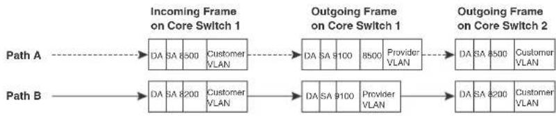
flowchart
graph LR
    A["Incoming Frame on Core Switch 1"] --> B["DA SA 6500 Customer VLAN"]
    C["Outgoing Frame on Core Switch 1"] --> D["DA SA 9100 Provider VLAN"]
    E["Outgoing Frame on Core Switch 2"] --> F["DA SA 8500 Customer VLAN"]
    G["Path A"] --> H["DA SA 8200 Customer VLAN"]
    I["Path B"] --> J["DA SA 8200 Customer VLAN"]
Legend:
T - Tagged port
U - Untagged port
XXXX - DMA or port group
Path A
Path B
As illustrated in Figure 29, the devices process the packets as follows:
- Path A: When Core Switch 1 receives the tagged packet from Edge Switch 1, it keeps the 8500 tag-type in the frame header (because the incoming port on Core Switch 1 is untagged) and adds the 9100 tag-type as it sends the packet to the uplink (Core Switch 2). In this case, the packet is double-tagged as it travels between the core devices.
- Path B: When Core Switch 1 receives the tagged packet from Edge Switch 2, it removes the 8200 tag-type and replaces (translates) it with the 9100 tag-type as it sends the packet to the uplink (Core Switch 2).
For more information, refer to "Configuring 802.1q tag-type translation" on page 310.
Configuration rules
- On the supported devices, you configure 802.1q tag-types per port region. Use the show running-config command at any level of the CLI to view port regions. Note that on Gigabit Ethernet modules, ports 1 and 2 belong to the same port region.
-
Since the uplink (to the provider cloud) and the edge link (to the customer port) must have different 802.1q tag-types, make sure the uplink and edge link are in different port regions.
-
If you configure a port with an 802.1q tag-type, the device automatically applies the 802.1q tag-type to all ports within the same port region.
- If you remove the 802.1q tag-type from a port, the device automatically removes the 802.1q tag-type from all ports within the same port region.
- Brocade does not recommend configuring different 802.1q tag-types on ports that are part of a multi-slot trunk. Use the same 802.1q tag-type for all ports in a multi-slot trunk.
- Multiple 802.1Q tag types can be assigned to an interface module. Depending on the module, an 802.1Q tag can be assigned to an individual port or to a group of ports. Table 65 describes the granularity at which each of the device interface modules can have 802.1Q tag-types assigned.
TABLE 65 802.1Q tag-type assignments by module
| module type 802.1Q tag-type assignment | |
| 4 x 10G per port | |
| 24 x 1G per 12 ports: | |
| 1 - 12, | |
| 13 - 24, | |
Enabling 802.1q tag-type translation
To enable 802.1q tag-type translation, configure an 802.1q tag-type on the provider core link, between the provider core switches (refer to Figure 28). Enter commands such as the following.
BigIron RX(config)# tag-type 9100 e 11 to 12 BigIron RX(config)# aggregated-vlan
Note that since ports 11 and 12 belong to the port region 9 - 16, the 802.1q tag-type actually applies to ports 9 - 16.
NOTE
Do not configure 802.1q tag-type translation on the edge link (to the customer edge switch).
Syntax: [no] tag-type
The
The
- If you specify a single port number, the 802.1q tag-type applies to all ports within the port region. For example, if you enter the command tag-type 9100 e 1, the device automatically applies the 802.1q tag to ports 1 – 8 since all of these ports are in the same port region (controlled by the same DMA). Use the show running-config command at any level of the CLI to view port regions. Note that on Gigabit Ethernet modules, ports 1 and 2 belong to the same port region.
- If the port that you specify is part of a multi-slot trunk, the device automatically applies the 802.1q tag-type to all of the ports that are part of the multi-slot trunk.
- If you do not specify a port or range of ports, the 802.1q tag-type applies to all Ethernet ports on the device.
Private VLANs
A private VLAN is a VLAN that has the properties of standard Layer 2 port-based VLANs but also provides additional control over flooding packets on a VLAN. Figure 30 shows an example of an application using a private VLAN.
FIGURE 30 Private VLAN used to secure communication between a workstation and servers

flowchart
graph TD
A["Firewall"] --> B["VLAN 7 primary"]
A --> C["VLAN 901, 903 community"]
A --> D["VLAN 902 isolated"]
B --> E["Computer"]
C --> F["Computer"]
D --> G["Computer"]
B --> H["Port-based VLAN"]
C --> I["Port-based VLAN"]
D --> J["Port-based VLAN"]
style A fill:#f9f,stroke:#333
style B fill:#ccf,stroke:#333
style C fill:#ccf,stroke:#333
style D fill:#ccf,stroke:#333
note1["A private VLAN secures traffic between a primary port and host ports."<br>Traffic between the hosts and the rest of the network must travel through the primary port."<br>Private VLAN"<br> note2["Forwarding among private VLAN ports"]
This example uses a private VLAN to secure traffic between hosts and the rest of the network through a firewall. Five ports in this example are members of a private VLAN. The first port (port 3/2) is attached to a firewall. The next four ports (ports 3/5, 3/6, 3/9, and 3/10) are attached to hosts that rely on the firewall to secure traffic between the hosts and the rest of the network. In this example, two of the hosts (on ports 3/5 and 3/6) are in a community private VLAN, and thus can communicate with one another as well as through the firewall. The other two hosts (on ports 3/9 and 3/10), are in an isolated VLAN and thus can communicate only through the firewall. The two hosts are secured from communicating with one another even though they are in the same VLAN.
By default, the private VLAN does not forward broadcast or unknown-unicast packets from outside sources into the private VLAN. If needed, you can override this behavior for broadcast packets, unknown-unicast packets, or both. (Refer to "Enabling broadcast, multicast or unknown unicast traffic to the private VLAN" on page 318.)
You can configure a combination of the following types of private VLANs:
- Primary – The primary private VLAN ports are “promiscuous”. They can communicate with all the isolated private VLAN ports and community private VLAN ports in the isolated and community VLANs that are mapped to the promiscuous port.
-
Secondary – The secondary private VLAN are secure VLANs that are separated from the rest of the network by the primary private VLAN. Every secondary private VLAN needs to be associated with a primary private VLAN. There are 2 different types of secondary private VLANs - 'community' and 'isolated' private VLANs:
-
Isolated – Broadcasts and unknown unicasts received on isolated ports are sent only to the primary port. They are not flooded to other ports in the isolated VLAN.
- Community – Broadcasts and unknown unicasts received on community ports are sent to the primary port and also are flooded to the other ports in the community VLAN.
Each private VLAN must have a primary VLAN. The primary VLAN is the interface between the secured ports and the rest of the network. The private VLAN can have any combination of community and isolated VLANs. (Refer to “Configuration rules” on page 316.)
Table 66 list the differences between private VLANs and standard VLANs.
TABLE 66 Comparison of private VLANs and standard port-based VLANs
| Forwarding behavior Private VLANs Standard VLANs | ||
| All ports within a VLAN constitute a common Layer broadcast domain | No Yes | |
| Broadcasts and unknown unicasts are forwarded to all the VLAN's ports by default | No (isolated VLAN)Yes (community VLAN) | Yes |
| Known unicasts Yes Yes | ||
Implementation notes
- The private VLAN implementation in the current release uses the CPU for forwarding packets on the primary VLAN's "promiscuous" port. Other forwarding is performed in the hardware. Support for the hardware forwarding in this feature sometimes results in multiple MAC address entries for the same MAC address in the device's MAC address table. In this case, each of the entries is associated with a different VLAN. The multiple entries are a normal aspect of the implementation of this feature and do not indicate a software problem.
- By default, the primary VLAN does not forward broadcast or unknown unicast packets into the private VLAN. You also can use MAC address filters to control traffic forwarded into and out of the private VLAN. If you are implementing the private VLAN on a Layer 2 Switch, you also can use ACLs to control the traffic into and out of the private VLAN.
Configuration notes
- When Private VLAN mappings are enabled, the BigIron RX forwards unknown unicast, unknown multicast, and broadcast packets in software. By default, the device forwards unknown unicast, unknown multicast, and broadcast packets in hardware.
- Release 02.4.00 supports private VLANs on untagged ports only. You cannot configure isolated, community, or primary VLANs on 802.1Q tagged ports.
- The device forwards all known unicast traffic in hardware. On the BigIron RX, multiple MAC entries do not appear in the MAC address table because the device transparently manages multiple MAC entries in hardware.
- There is currently no support for IGMP Snooping within Private VLANs. In order to let clients in Private VLANs get multicast traffic, IGMP Snooping must be disabled, so that all multicast packets are treated as unregistered multicast packets and get flooded in software to all the ports.
- You can configure private VLANs and dual-mode VLAN ports on the same device. However, the dual-mode VLAN ports cannot be members of Private VLANs.
- A primary VLAN can have multiple ports. All these ports are active, but the ports that will be used depends on the private VLAN mappings. Also, secondary VLANs (isolated and community VLANs) can be mapped to multiple primary VLAN ports. For example:
pvlan mapping 901 ethernet 1/2
pvlan mapping 901 ethernet 2/2
pvlan mapping 901 ethernet 3/2
Configuring a private VLAN
To configure a private VLAN, configure each of the component VLANs (isolated, community, and public) as a separate port-based VLAN:
- Use standard VLAN configuration commands to create the VLAN and add ports.
- Identify the type private VLAN type (isolated, community, or public)
- For the primary VLAN, map the other private VLANs to the ports in the primary VLAN
Configuration rules
NOTE
Although a private VLAN resides within a port-based VLAN, the VLAN is considered to be exclusively a private VLAN, not a port-based VLAN.
- You cannot use the private VLAN feature and the dual-mode VLAN port feature on the same device.
- The Spanning Tree Protocol (STP) is independent of this feature, and can be enabled or disabled in the individual port-based VLANs. However, private VLANs are not supported with single-instance STP (“single span”).
- You can configure only one private VLAN within a given port-based VLAN. Thus, you must configure a separate port-based VLAN for each private VLAN.
• Each private VLAN can have only one primary VLAN and can not belong LACP ports.
- Each private VLAN can have multiple isolated or community VLANs. You can use any combination of isolated or community VLANs with the primary VLAN. You do not need to use both isolated and community VLANs in the private VLAN.
- You can configure the primary VLAN before or after you configure the community or isolated VLANs. You are not required to configure a specific type of private VLAN before you can configure the other types.
- The ports in all three types of private VLANs can be untagged.
- The primary VLAN has only one active port. The primary VLAN can have more than one port, but only the lowest-numbered available port is active. The other ports provide redundancy.
- You cannot configure the default VLAN (VLAN 1) as a private VLAN.
Configuring an isolated or community private VLAN
To configure an isolated or a community private VLAN, use the following CLI methods.
Using the CLI
To configure a community private VLAN, enter commands such as the following.
BigIron RX(config)# vlan 901
BigIron RX(config-vlan-901)# untagged ethernet 3/5 to 3/6
BigIron RX(config-vlan-901)# pvlan type community
These commands create port-based VLAN 901, add ports 3/5 and 3/6 to the VLAN as untagged ports, then specify that the VLAN is a community private VLAN.
Syntax: untagged ethernet [to
Syntax: [no] pvlan type community | isolated | primary
The untagged command adds the ports to the VLAN.
The pvlan type command specifies that this port-based VLAN is a private VLAN.
- community – Broadcasts and unknown unicasts received on community ports are sent to the primary port and also are flooded to the other ports in the community VLAN.
- isolated – Broadcasts and unknown unicasts received on isolated ports are sent only to the primary port. They are not flooded to other ports in the isolated VLAN.
- primary – The primary private VLAN ports are “promiscuous”. They can communicate with all the isolated private VLAN ports and community private VLAN ports in the isolated and community VLANs that are mapped to the promiscuous port.
Configuring the primary VLAN
Use the following CLI method to configure the primary VLAN.
Using the CLI
To configure a primary private VLAN, enter commands such as the following.
BigIron RX(config)# vlan 7
BigIron RX(config-vlan-7)# untagged ethernet 3/2
BigIron RX(config-vlan-7)# pvlan type primary
BigIron RX(config-vlan-7)# pvlan mapping 901 ethernet 3/2
These commands create port-based VLAN 7, add port 3/2 as an untagged port, identify the VLAN as the primary VLAN in a private VLAN, and map the other private VLANs to the ports in this VLAN.
Syntax: untagged ethernet
Syntax: [no] pvlan type community | isolated | primary
Syntax: [no] pvlan mapping
The untagged command adds the ports to the VLAN.
The pvlan type command specifies that this port-based VLAN is a private VLAN. Specify primary as the type.
The pvlan mapping command identifies the other private VLANs for which this VLAN is the primary. The command also specifies the primary VLAN ports to which you are mapping the other private VLANs.
- The
parameter specifies another private VLAN. The other private VLAN you want to specify must already be configured. - The ethernet
parameter specifies the primary VLAN port to which you are mapping all the ports in the other private VLAN (the one specified by ).
Enabling broadcast, multicast or unknown unicast traffic to the private VLAN
To enhance private VLAN security, the primary private VLAN does not forward broadcast or unknown unicast packets to its community and isolated VLANs. For example, if port 3/2 in Figure 30 on page 314 receives a broadcast packet from the firewall, the port does not forward the packet to the other private VLAN ports (3/5, 3/6, 3/9, and 3/10).
This forwarding restriction does not apply to traffic from the private VLAN. The primary port does forward broadcast and unknown unicast packets that are received from the isolated and community VLANs. For example, if the host on port 3/9 sends an unknown unicast packet, port 3/2 forwards the packet to the firewall.
If you want to remove the forwarding restriction, you can enable the primary port to forward broadcast or unknown unicast traffic, if desired, using the following CLI method. You can enable or disable forwarding of broadcast or unknown unicast packets separately.
Using the CLI
To configure the ports in the primary VLAN to forward broadcast, multicast or unknown unicast traffic received from sources outside the private VLAN, enter the following commands at the global CONFIG level of the CLI.
BigIron RX(config)# pvlan-preference broadcast flood
BigIron RX(config)# pvlan-preference unknown-unicast flood
These commands enable forwarding of broadcast, multicast and unknown-unicast packets to ports within the private VLAN. To again disable forwarding, enter a command such as the following.
BigIron RX(config)# no pvlan-preference broadcast flood
This command disables forwarding of broadcast packets within the private VLAN.
Syntax: [no] pvlan-preference broadcast | unknown-unicast flood
CLI example for Figure 30
To configure the private VLANs shown in Figure 30 on page 314, enter the following commands.
BigIron RX(config)# vlan 901
BigIron RX(config-vlan-901)# untagged ethernet 3/5 to 3/6
BigIron RX(config-vlan-901)# pvlan type community
BigIron RX(config-vlan-901)# exit
BigIron RX(config)# vlan 902
BigIron RX(config-vlan-902)# untagged ethernet 3/9 to 3/10
BigIron RX(config-vlan-902)# pvlan type isolated
BigIron RX(config-vlan-902)# exit
BigIron RX(config)# vlan 903
BigIron RX(config-vlan-903)# untagged ethernet 3/5 to 3/6
BigIron RX(config-vlan-903)# pvlan type community
BigIron RX(config-vlan-903)# exit
BigIron RX(config)# vlan 7
BigIron RX(config-vlan-7)# untagged ethernet 3/2
BigIron RX(config-vlan-7)# pvlan type primary
BigIron RX(config-vlan-7)# pvlan mapping 901 ethernet 3/2
BigIron RX(config-vlan-7)# pvlan mapping 902 ethernet 3/2
BigIron RX(config-vlan-7)# pvlan mapping 903 ethernet 3/2
Other VLAN features
Allocating memory for more VLANs or virtual routing interfaces
By default, you can configure up to 512 VLANs and virtual routing interfaces on the device. Although this is the default maximum, the device can support up to 4089 VLANs and 4095 virtual routing interfaces. (VLAN IDs 0, 4090, 4091, 4092 and 4095 are reserved.)
NOTE
If many of your VLANs will have an identical configuration, you might want to configure VLAN groups.
If you need to configure more than 512 VLANs, enter commands such as the following at the global CONFIG level of the CLI.
BigIron RX(config)# system-max vlan 2048 BigIron RX(config)# write memory BigIron RX(config)# end BigIron RX# reload
Syntax: [no] system-max vlan
The
Hardware flooding for Layer 2 multicast and broadcast packets
Broadcast and multicast packets do not have a specific recipient. In order for these "special" packets to reach their intended recipient, they needed to be sent on all ports of the VLAN (or "flooded" across the VLAN).
By default, the device performs hardware flooding for Layer 2 multicast and broadcast packets. (Layer 2 multicast packets have a multicast address in the destination MAC address field.) However, if uplink VLANs or protocol-based VLANs are configured, this default behavior is overridden and software flooding is enabled.
You can disable hardware flooding for Layer 2 multicast and broadcast packets on a per-VLAN basis. For example:
BigIron RX(config)# BigIron RX(config)# vlan 2 BigIron RX(config-vlan-2)# no multicast-flooding
Syntax: [no] multicast-flooding
NOTES:
- This feature is supported on the 10 Gigabit Ethernet module.
- This feature cannot be enabled on an empty VLAN; the VLAN must already have ports assigned to it prior to enabling this feature.
- This feature is not supported on Layer 3 protocol-based VLANs.
-
This feature is not supported on private VLANs.
-
You cannot enable this feature on the designated management VLAN for the device.
- If you enable this feature on a VLAN that includes a trunk group, hardware flooding for Layer 2 multicast and broadcast packets occurs only on the trunk group's primary port. Multicast and broadcast traffic for the other ports in the trunk group is handled by software.
Unknown unicast flooding on VLAN ports
Unknown unicast packets do not have a specific (or unicast) recipient. In order for these "special" packets to reach their intended recipient, they needed to be sent on all ports of the VLAN (or "flooded" across the VLAN).
By default, the device performs hardware flooding for unknown unicast packets. However, if uplink VLANs or protocol-based VLANs are configured, this default behavior is overridden and software flooding is enabled.
To disable unicast hardware flooding on a VLAN ports and enable software flooding, enter commands such as the following.
BigIron RX(config)# vlan 2
BigIron RX(config-vlan-2)# no unknown-unicast-flooding
BigIron RX(config-vlan-2)# exit
BigIron RX(config)# reload
Syntax: [no] unknown-unicast-flooding
Flow based MAC learning
In this release, the cpu-flooding command that disables hardware flooding of unknown unicast, multicast, and broadcast packets on all VLAN has been added. When using this command, unknown unicast packets will go to the CPU and will be CPU forwarded. Source MAC learning will be done by CPU. The first packet for unknown DA will go to the CPU and CPU will program the hardware on demand. Any supplemental packets will be forwarded by the hardware. This will allow MAC learning only where necessary and at a system level to allow more than 16k MACs. In addition, a MAC will be learned only on the port or packet processor it was received.
Enabling CPU flooding
To enable CPU based flooding of unknown unicast, broadcast and multicast packets, enter the following command at the global configuration level.
BigIron RX(config)# cpu-flooding
To enable flow based MAC learning and CPU flooding for unknown unicast packets only, enter the following command at the global configuration level.
BigIron RX(config)# cpu-flooding unknown-unicast
To enable CPU based flooding for broadcast and multicast packets, enter the following command at the global configuration level.
BigIron RX(config)# cpu-flooding multicast
Syntax: [no] cpu-flooding [multicast] [unknown-unicast]
Use the multicast parameter to specify CPU flooding for broadcast and multicast packets.
Use the unknown-unicast parameter to specify CPU flooding for unknown unicast packets only.
NOTE
This command does not erase any multicast or unknown-unicast flooding configuration. If this command is enabled, then it supersedes the per-vlan configuration.
Configuring uplink ports within a port-based VLAN
You can configure a subset of the ports in a port-based VLAN as uplink ports. When you configure uplink ports in a port-based VLAN, the device sends all broadcast and unknown-unicast traffic from a port in the VLAN to the uplink ports, but not to other ports within the VLAN. Thus, the uplink ports provide tighter broadcast control within the VLAN.
For example, if two ports within a port-based VLAN are Gigabit ports attached to the network and the other ports in the VLAN are 10/100 ports attached to clients, you can configure the two ports attached to the network as uplink ports. In this configuration, broadcast and unknown-unicast traffic in the VLAN does not go to all ports in the VLAN. The traffic goes only to the uplink ports. The clients on the network do not receive broadcast and unknown-unicast traffic from other ports, including other clients.
To configure a port-based VLAN containing uplink ports, enter commands such as the following.
BigIron RX(config)# vlan 10 by port
BigIron RX(config-vlan-10)# untag ethernet 1/1 to 1/24
BigIron RX(config-vlan-10)# untag ethernet 2/1 to 2/2
BigIron RX(config-vlan-10)# uplink-switch ethernet 2/1 to 2/2
Syntax: [no] uplink-switch ethernet
In this example, 24 ports on a 10/100 module and two Gigabit ports on a Gigabit module are added to port-based VLAN 10. The two Gigabit ports are then configured as uplink ports.
Configuring control protocols in VLANs
You can configure the following protocols on a VLAN:
- MRP (Refer to Chapter 14, "Metro Ring Protocol (MRP) Phase 1 and 2".)
- VSRP (Refer to Chapter 15, "Virtual Switch Redundancy Protocol (VSRP)".)
- STP (Refer to Chapter 12, "Configuring Spanning Tree Protocol".)
- RSTP (Refer to Chapter 13, "Configuring Rapid Spanning Tree Protocol".)
Other configuration options
You can also configure the following on a VLAN:
- "Configuring static ARP entries" on page 136
- "Setting maximum frame size per PPCR" on page 180
Displaying VLAN information
After you configure the VLANs, you can view and verify the configuration.
Displaying VLAN information
Enter the following command at any CLI level.
BigIron RX# show vlan
Configured PORT-VLAN entries: 3
Maximum PORT-VLAN entries: 4095
Default PORT-VLAN id: 1
PORT-VLAN 1, Name DEFAULT-VLAN, Priority Level0
L2 protocols : NONE
Untagged Ports : ethe 2/1 to 2/24 ethe 3/1 to 3/24 eth
PORT-VLAN 2, Name [None], Priority Level0
L2 protocols : NONE
ip-protocol VLAN, Dynamic port disabled
Name: basic
PORT-VLAN 1001, Name [None], Priority Level0
L2 protocols : MRP
Tagged Ports : ethe 3/1 ethe 3/12 to 3/13 ethe 3/24
Syntax: show vlan [
Enter a VLAN ID if you want to display information for a specific VLAN.
The output shows the following information.
TABLE 67 Output of show vlan
| This field... Displays... | |
| Configured PORT-VLAN entries Number of port-based VLANs in the configuration. | |
| Maximum PORT-VLAN entries: 4095 | Maximum number of port-based VLANs that you can configure. Note however, IDs 4091 and 4092 are reserved for control purposes. |
| Default PORT-VLAN id ID of the default VLAN. | |
| PORT-VLAN ID of the port-based VLAN | |
| Name Name of the port-based VLAN. [None] appears if a name has not been assigned. | |
| Priority Level Priority level assigned to the port-based VLAN | |
| L2 protocols Layer 2 control protocol configured on the VLAN | |
| Untagged/Tagged Ports ID of the untagged or tagged ports that are members of the VLAN | |
| (protocol-based VLANs) | If protocol based VLANs are configured, their type and name appear after the list of ports. |
Displaying VLAN information for specific ports
To determine which VLANs a port is a member of, enter the following command.
BigIron RX# show vlan e 4/1
Port 4/1 is a member of 2 VLANs
VLANs 1 100
Syntax: show vlan ethernet
The ethernet
The output shows the following information.
TABLE 68 Output of show vlan ethernet
| This field... Displays... | |
| Port//is The number of VLANs a port is a member of. a member of # VLANs | |
| VLANs The IDs of the VLANs that the port is a member of. |
Displaying VLAN status and port types
To display detailed information about the state, port types, port modes, of a VLAN, as well as control protocols configured on the VLAN, enter the following command.
BigIron RX# show vlan detail
Untagged Ports : ethe 2/1 to 2/24 ethe 4/4
Tagged Ports : None
Dual-mode Ports : ethe 3/1 to 3/24 ethe 4/1 to 4/3
Default VLAN : 1
Control VLAN : 4095
VLAN Tag-type : 0x8100
PORT-VLAN 1, Name DEFAULT-VLAN, Priority Level0
Port Type Tag-Mode Protocol State
2/1 PHYSICAL UNTAGGED NONE DISABLED
2/2 PHYSICAL UNTAGGED NONE DISABLED
2/3 PHYSICAL UNTAGGED NONE DISABLED
2/4 PHYSICAL UNTAGGED NONE DISABLED
2/5 PHYSICAL UNTAGGED NONE DISABLED
.
. (output edited for brevity)
.
4/1 PHYSICAL UNTAGGED NONE FORWARDING
4/2 PHYSICAL UNTAGGED NONE FORWARDING
4/3 PHYSICAL UNTAGGED NONE FORWARDING
4/4 PHYSICAL UNTAGGED NONE DISABLED
PORT-VLAN 100, Name [None], Priority Level0
Port Type Tag-Mode Protocol State
4/1 PHYSICAL TAGGED STP FORWARDING
4/2 PHYSICAL TAGGED STP BLOCKING
Syntax: show vlan detail
Enter the ID of a VLAN if you want information for a specific VLAN.
The output shows the following information.
TABLE 69 Output of show vlan detail
| This field... Displays... | |
| Untagged Ports This line appears if you do not specify a VLAN. It lists all the ports that are configured as untagged ports in all the VLANs on the device. | |
| Tagged Ports This line appears if you do not specify a VLAN. It lists all the ports that are configured as tagged ports in all the VLANs on the device. | |
| Dual-mode ports This line appears if you do not specify a VLAN. It lists all the ports that are configured as dual-mode ports in all the VLANs on the device. | |
| Default VLAN ID of the default VLAN | |
| Control VLAN ID of the control VLAN | |
| PORT-VLAN #, Name, Priority Level Information for each VLAN in the output begins with the VLAN type and its ID, name and priority level. Then ports that are members of the VLAN are listed, with the following information: | |
| Port Port | |
| Type Port type: physical or trunk | |
| Tag-Mode | Tag mode of the port: untagged, tagged, or dual-mode |
| Protocol | Protocol configured on the VLAN. |
| State | Current state of the port such as disabled, blocking, forwarding, etc. |
Displaying VLAN group information
To display information about VLAN groups, enter the following command.
BigIron RX# show vlan-group 10
Configured VLAN-Group entries: 1
Maximum VLAN-Group entries : 32
VLAN-GROUP 10
Number of VLANs: 4
VLANs: 10 to 13
Tagged ports: ethe 3/1
Syntax: show vlan-group [vlan-group-id] [| [begin
The output shows the following information.
TABLE 70 Output of show vlan ethernet
| This field... Displays... | |
| Configured VLAN-Group entries | Number of VLAN groups that have been configured on the device. |
| Maximum VLAN-Group entries | Maximum number of VLAN groups that can be configured on the device. |
| VLAN-Group # | ID of the VLAN group |
| VLANs | VLANs that belong to the VLAN group. |
| Tagged ports: | Type and ID of the tagged ports that are members of the VLAN group |
Transparent firewall mode
The Transparent Firewall mode allows the device to switch self-originated control packets. By default, Brocade devices will drop control packets received with the device's MAC address as the packet's source MAC address (i.e. self originated packet from the switch or router). Under the Transparent Firewall mode, switching of self-originated packets is allowed. The Transparent Firewall mode feature is a per VLAN configuration and is disabled by default.
Enabling a transparent firewall
To set the mode to transparent, enter a command such as the following.
BigIron RX(config-vlan-10)# transparent-fw-mode
To set the mode to routed, enter a command such as the following.
BigIron RX(config-vlan-10)# no transparent-fw-mode
Syntax: [no] transparent-fw-mode
IEEE 802.1D Spanning Tree Protocol (STP)
The BigIron RX supports Spanning Tree Protocol (STP) as described in the IEEE 802.10-1998 specification. STP eliminates Layer 2 loops in networks, by selectively blocking some ports and allowing other ports to forward traffic, based on configurable bridge and port parameters. STP also ensures that the least cost path is taken when multiple paths exist between ports or VLANs. If the selected path fails, STP searches for and then establishes an alternate path to prevent or limit retransmission of data.
NOTE
The total number of supported STP, RSTP, or MSTP indices is 128.
Enabling or disabling STP
STP is disabled by default on the device. Thus, new VLANs you configure on the device have STP disabled by default. Table 71 lists the default STP states for the device.
TABLE 71 Default STP states
| Device type | Default STP type | Default STP state | Default STP state of new VLANs |
| BigIron RX | Brocade's multiple instances of spanning tree | Disabled | Disabled |
By default, each VLAN on a BigIron RX runs a separate spanning tree instance. Each device has one VLAN (VLAN 1) by default that contains all of its ports. However, if you configure additional port-based VLANs on a device, then each of those VLANs on which STP is enabled and VLAN 1 all run separate spanning trees.
You can enable or disable STP on the following levels:
- Globally – Affects all VLANs on the device.
- Individual VLAN – Affects all ports within the specified VLAN. When you enable or disable STP within a VLAN, the setting overrides the global setting. Thus, you can enable STP for the ports within a VLAN even when STP is globally disabled, or disable the ports within a port-based VLAN when STP is globally enabled.
- Individual port – Affects only the individual port. However, if you change the STP state of the primary port in a trunk group, the change affects all ports in the trunk group.
Enabling or disabling STP globally
Use the following methods to enable or disable STP on the device on which you have not configured VLANs.
NOTE
When you configure a VLAN, the VLAN inherits the global STP settings. However, once you begin to define a VLAN, you can no longer configure standard STP parameters globally using the CLI. From that point on, you can configure STP only within individual VLANs.
To enable STP for all ports in all VLANs on a device, enter the following command.
BigIron RX(config)# spanning-tree
This command enables a separate spanning tree in each VLAN, including the default VLAN.
Syntax: [no] spanning-tree
Enabling or disabling STP on a VLAN
Use the following procedure to disable or enable STP on a device on which you have configured a VLAN. Changing the STP state in a VLAN affects only that VLAN.
To enable STP for all ports in a port-based VLAN, enter commands such as the following.
BigIron RX(config)# vlan 10
BigIron RX(config-vlan-10)# spanning-tree
Syntax: [no] spanning-tree
Enabling or disabling STP on a port
Use the following procedure to disable or enable STP on an individual port.
NOTE
If you change the STP state of the primary port in a trunk group, the change affects all ports in the trunk group.
To enable STP on an individual port, enter commands such as the following.
BigIron RX(config)# interface 1/1
BigIron RX(config-if-e1000-1/1)# spanning-tree
Syntax: [no] spanning-tree
Default STP bridge and port parameters
Table 72 lists the default STP bridge parameters. The bridge parameters affect the entire spanning tree. If you are using MSTP, the parameters affect the VLAN. If you are using SSTP, the parameters affect all VLANs that are members of the single spanning tree.
TABLE 72 Default STP bridge parameters
| Parameter Description Default and valid values | |
| Forward Delay The period of time a bridge will wait (the listen and learn period) before beginning to forward data packets. | 15 secondsPossible values: 4 - 30 seconds |
| Maximum Age The interval a bridge will wait for a hello packet from the root bridge before initiating a topology change. | 20 secondsPossible values: 6 - 40 seconds |
| Hello Time The interval of time between each configuration BPDU sent by the root bridge. | 2 secondsPossible values: 1 - 10 seconds |
| Priority A parameter used to identify the root bridge in a spanning tree (instance of STP). The bridge with the lowest value has the highest priority and is the root.A higher numerical value means a lower priority; thus, the highest priority is 0. | 32768Possible values: 0 - 65535 |
NOTE
If you plan to change STP bridge timers, Brocade recommends that you stay within the following ranges, from section 8.10.2 of the IEEE specification.
- 2 * (forward_delay -1) >= max_age
- max_age >= 2 * (hello_time +1)
Table 73 lists the default STP port parameters. The port parameters affect individual ports and are separately configurable on each port.
TABLE 73 Default STP port parameters
| Parameter Description Default and valid values | |
| Priority The preference that STP gives this port relative to other ports for forwarding traffic out of the spanning tree.A higher numerical value means a lower priority; thus, the highest priority is 8. | 128Possible values: 8 - 252, configurable in increments of 4 |
| Path Cost The cost of using the port to reach the root bridge. When selecting among multiple links to the root bridge, STP chooses the link with the lowest path cost and blocks the other paths. Each port type has its own default STP path cost. | 10 Mbps - 100100 Mbps - 19Gigabit - 410 Gigabit - 2Possible values are 1- 65535 |
Changing STP bridge parameters
To change a BigIron RX's STP bridge priority to the highest value, so as to make the device the root bridge, enter the following command.
BigIron RX(config)# vlan 20
BigIron RX(config-vlan-20)# spanning-tree priority 0
To make this change in the default VLAN, enter the following commands.
BigIron RX(config)# vlan 1
BigIron RX(config-vlan-1)# spanning-tree priority 0
Syntax: [no] spanning-tree [forward-delay
You can specify some or all of the parameters on the same command line. For information on parameters, possible values and defaults, refer to Table 72 on page 328.
NOTE
The hello-time
Changing STP port parameters
To change the path and priority costs for a port, enter commands such as the following.
BigIron RX(config)# vlan 10
BigIron RX(config-vlan-10)# spanning-tree ethernet 1/5 path-cost 15 priority 64
Syntax: spanning-tree ethernet
The ethernet
For descriptions of path cost and priority, their default and possible values, refer to Table 73 on page 329. If you enter a priority value that is not divisible by four, the software rounds it to the nearest value.
The disable | enable parameter disables or re-enables STP on the port. The STP state change affects only this VLAN. The port's STP state in other VLANs is not changed.
STP root guard
In release 02.3.00, a new security feature that allows a port to run STP but not allow the connected device to become the Root has been added. The STP Root Guard feature provides a way to enforce the root bridge placement in the network and trigger errors if any changes from the root bridge placement are detected. This feature allows STP to interoperate with user network bridges while still maintaining the bridged network topology that the administrator requires.
When Root Guard is enabled on a port, it keeps the port in designated FORWARDING state. If the port receives a superior STP BPDU, it sets the port into BLOCKING and triggers a log message and an SNMP trap. No further traffic will be forwarded on this port. This allows the bridge to prevent traffic from being forwarded on ports connected to rogue or misconfigured STP bridges.
Root Guard should be configured on all ports where the root bridge should not appear. In this way, the core bridged network can be cut off from the user network by establishing a protective perimeter around it.
Once the port stops receiving superior BPDUs, root protect will automatically set the port back to a FORWARDING state after the timeout period has expired.
NOTE
Root Guard may prevent network connectivity if improperly configured. It needs to be configured on the perimeter of the network rather than the core.
Enabling STP root guard
A STP Root Guard is configured on a per interfaces basis. To enable a Root Guard, enter a command such as the following.
BigIron RX (config)#interface ethernet 5/5
BigIron RX(config-if-e10000-5/5) spanning-tree root-protect
Syntax: [no] spanning-tree root-protect
Enter the no form of the command to disable STP Root Guard on the port.
Setting the STP root guard timeout period
To configure the STP Root protect timeout period globally, enter a command such as the following.
BigIron RX(config)# spanning-tree root-protect timeout 120
Syntax: spanning-tree root-protect timeout
The timeout in seconds parameter allows you to set the timeout period. The timeout period may be configured to anything between 5 and 600 seconds. Default is 30 seconds.
Displaying the STP root guard
To display the STP Root Guard state, enter the show spanning-tree root-protect command.
BigIron RX#show spanning-tree root-protect
Port VLAN Current State
13/6 3 Consistent state
13/9 2 Inconsistent state (29 seconds left on timer)
Syntax: show spanning-tree root-protect
Sample Syslog messages
A Syslog message such as the following is generated after the Root Guard blocks a port.
STP: Root Guard Port 12/21, VLAN 10 inconsistent (Received superior BPDU)
A Syslog message such as the following is generated after the Root Guard unblocks a port.
STP: Root Guard Port 12/21, VLAN 10 consistent (Timeout)
Spanning Tree Protocol (STP) BPDU guard
STP protection provides the ability to prohibit an end station from initiating or participating in an STP topology. The STP BPDU Guard is used to keep all active network topologies predictable.
The spanning-tree protocol detects and eliminates logical loops in a redundant network by selectively blocking some data paths and allowing only some data paths to forward traffic.
In an STP environment, switches, end stations, and other Layer 2 devices use Bridge Protocol Data Units (BPDUs) to exchange information that STP will use to determine the best path for data flow. When a Layer 2 device is powered ON and connected to the network, or when a Layer 2 device goes down, it sends out an STP BPDU, triggering an STP topology change.
In some instances, it is unnecessary for a connected device, such as an end station, to initiate or participate in an STP topology change. In this case, you can enable the STP BPDU Guard feature on the Brocade port to which the end station is connected. Brocade's STP BPDU Guard feature disables the connected device's ability to initiate or participate in an STP topology change, by dropping all BPDUs received from the connected device.
Enabling STP protection
You can enable STP BPDU Guard on a per-port basis.
To prevent an end station from initiating or participating in STP topology changes, enter the following command at the interface level of the CLI.
BigIron RX(config) interface ethe 2/1 BigIron RX(config-if-e1000-2/1)# spanning-tree protect
This command causes the port to drop STP BPDUs sent from the device on the other end of the link.
Syntax: [no] spanning-tree protect
Enter the no form of the command to disable BPDU Guard on the port and remove the spanning-tree protect do-disable feature if they are configured.
Enabling BPDU Guard and disabling a port that receives BPDUs
You can enable BPDU Guard on a port and at the same time configure a port to be disabled when it receives a BPDU. Enter the following commands.
BigIron RX(config) interface ethe 2/1 BigIron RX(config-if-e1000-2/1)#spanning-tree protect do-disable
Syntax: [no] spanning-tree protect do-disable
If both spanning-tree protect and spanning-tree protect do-disable are configured on an interface, spanning-tree protect do-disable takes precedence. This means that when the port receives a BPDU, the port will drop the BPDU and disable the port.
If you issue a no spanning-tree protect do-disable command, the port will be re-enabled and will no longer be disabled when it receives a BPDU. The following message is displayed when you enter the no spanning-tree protect do-disable command.
This command removes only "spanning-tree protect do-disable". To remove "spanning-tree protect", please issue a separate command "no spanning-tree protect".
Displaying STP information
You can display the following STP information:
- All the global and interface STP settings
• Detailed STP information for each interface
• STP state information for a VLAN
• STP state information for an individual interface
Displaying STP information for an entire device
To display STP information, enter the following command at any level of the CLI.
BigIron RX# show spanning-tree vlan 10
VLAN 10 - STP instance 1
STP Bridge Parameters:
| Bridge Identifier hex | Bridge MaxAge sec | Bridge Hello sec | Bridge FwdDly sec | Hold Time sec | LastTopology Change sec | Topology Change cnt |
| 8000000480a04000 | 20 | 2 | 15 | 1 | 0 | 0 |
| RootBridge Identifier hex | RootPath Cost | DesignatedBridge Identifier hex | Root Port | Max Age sec | Hel lo sec | Fwd Dly sec |
| 8000000480a04000 | 0 | 8000000480a04000 | Root | 20 | 2 | 15 |
STP Port Parameters:
| Port Num | Prio rity | Path Cost | State | Designat- ed Cost | Designated Root | Designated Bridge |
| 1/3 | 128 | 4 | DISABLED | 0 | 000000000000000 | 000000000000000 |
| 1/13 | 128 | 4 | DISABLED | 0 | 000000000000000 | 000000000000000 |
Syntax: show spanning-tree [vlan
The vlan
The pvst-mode parameter displays STP information for the device's Per VLAN Spanning Tree (PVST+) compatibility configuration. Refer to "PVST/PVST+ compatibility" on page 343.
The
The detail parameter and its additional optional parameters display detailed information for individual ports. Refer to “Displaying detailed STP information for each interface” on page 335.
The show spanning-tree command shows the following information.
TABLE 74 CLI display of STP information
| This field... Displays... |
| Global STP parameters |
| VLAN ID The port-based VLAN that contains this spanning tree and the number ofSTP instance on the VLAN. VLAN 1 is the default VLAN. If you have not configured port-based VLANs on this device, all STP information is for VLAN 1. |
Bridge parameters
TABLE 74 CLI display of STP information (Continued)
| This field... | Displays... |
| Bridge Identifier The ID assigned by STP to this bridge for this spanning tree in hexadecimal.NOTE: If this address is the same as the Root ID, then this device or VLAN is the root bridge for its spanning tree. | |
| Bridge MaxAge sec The number of seconds this bridge waits for a hello message from the root bridge before deciding the root has become unavailable and performing a reconvergence. | |
| Bridge Hello sec The interval between each configuration BPDU sent by the bridge. | |
| Bridge FwdDly sec The number of seconds this bridge waits following a topology change and consequent reconvergence. | |
| Hold Time sec The minimum number of seconds that must elapse between transmissions of consecutive Configuration BPDUs on a port. | |
| Last Topology Chang sec The number of seconds since the last time a topology change occurred. | |
| Topology Change cnt The number of times the topology has changed since this device was reloaded. | |
| Root bridge parameters | |
| Root Identifier The ID assigned by STP to the root bridge for this spanning tree in hexadecimal. | |
| Root Cost The cumulative cost from this bridge to the root bridge. If this device is the root bridge, then the root cost is 0. | |
| DesignatedBridge Identifier The designated bridge to which the root port is connected. The designated bridge is the device that connects the network segment on the port to the root bridge. | |
| Root Port The port on this device that connects to the root bridge. If this device is the root bridge, then the value is “Root” instead of a port number. | |
| Max Age sec | The number of seconds this root bridge waits for a hello message from the bridges before deciding a bridges has become unavailable and performing a reconvergence. |
| Hello sec | The interval between each configuration BPDU sent by the root bridge. |
| FwdDly sec | The number of seconds this root bridge waits following a topology change and consequent reconvergence. |
| Port STP parameters | |
| Port Num | The port number. |
| Priority | NOTE: If you configure this value, specify it in decimal format. Refer to “Changing STP port parameters” on page 330. |
| This field... Displays... | |
| State The port's STP state. The state can be one of the following:BLOCKING - STP has blocked Layer 2 traffic on this port to prevent a loop. The device or VLAN can reach the root bridge using another port, whose state is FORWARDING. When a port is in this state, the port does not transmit or receive user frames, but the port does continue to receive STP BPDUs.DISABLED - The port is not participating in STP. This can occur when the port is disconnected or STP is disabled on the port.FORWARDING - STP is allowing the port to send and receive frames.LISTENING - STP is responding to a topology change and this port is listening for a BPDU from neighboring bridges in order to determine the new topology. No user frames are transmitted or received during this state.LEARNING - The port has passed through the LISTENING state and will change to the BLOCKING or FORWARDING state, depending on the results of STP's reconvergence. The port does not transmit or receive user frames during this state. However, the device can learn the MAC addresses of frames that the port receives during this state and make corresponding entries in the MAC table. | |
| Design Cost The cost to the root bridge as advertised by the designated bridge that is connected to this port. If the designated bridge is the root bridge itself, then the cost is 0. The identity of the designated bridge is shown in the Design Bridge field. | |
| Designated Root The root bridge as recognized on this port. The value is the same as the root bridge ID listed in the Root ID field. | |
| Designated Bridge The bridge as recognized on this port. | |
Displaying detailed STP information for each interface
To display the detailed STP information, enter the following command at any level of the CLI.
BigIron RX# show spanning-tree detail vlan 10
VLAN 10 - STP instance 1
STP Bridge Parameters:
Bridge identifier - 0x8000000480a04000
Root bridge - 0x8000000480a04000
Control ports - ethe 1/3 ethe 1/13
Active global timers - None
STP Port Parameters:
Port 1/3 - DISABLED
Port 1/13 - DISABLED
VLAN 20 - STP instance 2
STP Bridge Parameters:
Bridge identifier - 0x8000000480a04000
Root bridge - 0x8000000480a04000
Control ports - ethe 1/3 ethe 1/13
Active global timers - None
STP Port Parameters:
Port 1/3 - DISABLED
Port 1/13 - DISABLED
If a port is disabled, the only information shown by this command is "DISABLED". If a port is enabled, this display shows the following information.
Syntax: show spanning-tree detail [vlan
The vlan
The ethernet
The
NOTE
If the configuration includes VLAN groups, the show span detail command displays the master VLANs of each group but not the member VLANs within the groups. However, the command does indicate that the VLAN is a master VLAN. The show span detail vlan
The show spanning-tree detail command shows the following information for each VLAN participating in the spanning tree.
TABLE 75 CLI display of detailed STP information for ports
| This field... Displays... |
| VLAN ID The VLAN that contains the listed ports and the number of STP instances on this VLAN.The STP type can be one of the following:Brocade proprietary multiple Spanning TreeIEEE 802.1Q Single Spanning Tree (SSTP)NOTE: If STP is disabled on a VLAN, the command displays the following message instead: “Spanning-tree of port-vlanis disabled.” |
STP bridge parameters
Bridge identifier The STP identity of this device.
Root The ID assigned by STP to the root bridge for this spanning tree.
Control ports The ports in the VLAN.
Active global timers The global STP timers that are currently active, and their current values.
The following timers can be listed:
- Hello – The interval between Hello packets. This timer applies only to the root bridge.
- Topology Change (TC) – The amount of time during which the topology change flag in Hello packets will be marked, indicating a topology change. This timer applies only to the root bridge.
- Topology Change Notification (TCN) – The interval between Topology Change Notification packets sent by a non-root bridge toward the root bridge. This timer applies only to non-root bridges.
TABLE 75 CLI display of detailed STP information for ports (Continued)
| This field... Displays... | |
| STP port parameters | |
| Port number and STP state The internal port number and the port's STP state.The internal port number is one of the following:The port's interface number, if the port is the designated port for the LAN.The interface number of the designated port from the received BPDU, if the interface is not the designated port for the LAN.The state can be one of the following:BLOCKING - STP has blocked Layer 2 traffic on this port to prevent a loop. The device or VLAN can reach the root bridge using another port, whose state is FORWARDING. When a port is in this state, the port does not transmit or receive user frames, but the port does continue to receive STP BPDUs.DISABLED - The port is not participating in STP. This can occur when the port is disconnected or STP is administratively disabled on the port.FORWARDING - STP is allowing the port to send and receive frames.LISTENING - STP is responding to a topology change and this port is listening for a BPDU from neighboring bridges in order to determine the new topology. No user frames are transmitted or received during this state.LEARNING - The port has passed through the LISTENING state and will change to the BLOCKING or FORWARDING state, depending on the results of STP's reconvergence. The port does not transmit or receive user frames during this state. However, the device can learn the MAC addresses of frames that the port receives during this state and make corresponding entries in the MAC table.NOTE: If the state is DISABLED, no further STP information is displayed for the port. |
Displaying STP information for the specified Ethernet interface
To display the STP information for the specified Ethernet interface, enter the following command at any level of the CLI.
BigIron RX# show xstp Ethernet 3/1
STP information:
STP Port Parameters:
VLAN ID: 11
| Port | Prio | Path | State | Designat- | Designated | Designated |
| Num | rity | Cost | ed Cost | Root | Bridge | |
| 3/1 | 128 | 4 | FORWARDING | 0 | 8000000cdbf5ee00 | 8000000cdbf5ee00 |
STP Port Parameters:
VLAN ID: 12
| Port | Prio | Path | State | Designat- | Designated | Designated |
| Num | rity | Cost | ed Cost | Root | Bridge | |
| 3/1 | 128 | 4 | FORWARDING | 0 | 8000000cdbf5ee00 | 8000000cdbf5ee00 |
RSTP information:
No RSTP-configured VLANs for the port 3/1
MSTP information:
No MSTP-configured VLANs for the port 3/1
Syntax: show xstp ethernet
The ethernet
TABLE 76 CLI display of STP information for the specified Ethernet interface
| This field... Displays... | |
| The STP/RSTP/MSTP protocol information for the specified ethernet interface. | |
| NOTE: If the Ethernet interface is not added to any STP enabled VLANs, the command displays the following message instead: "No STP-configured VLANs for the port". | |
| STP port parameters | |
| Port Num The port number. | |
| Priority | NOTE: If you configure this value, specify it in decimal format. Refer to “Changing STP port parameters” on page 330. |
| Path Cost The port's STP path cost. | |
| State The port's STP state. The state can be one of the following:BLOCKING - STP has blocked Layer 2 traffic on this port to prevent a loop. The device or VLAN can reach the root bridge using another port, whose state is FORWARDING. When a port is in this state, the port does not transmit or receive user frames, but the port does continue to receive STP BPDUs.DISABLED - The port is not participating in STP. This can occur when the port is disconnected or STP is disabled on the port.FORWARDING - STP is allowing the port to send and receive frames.LISTENING - STP is responding to a topology change and this port is listening for a BPDU from neighboring bridges in order to determine the new topology. No user frames are transmitted or received during this state.LEARNING - The port has passed through the LISTENING state and will change to the BLOCKING or FORWARDING state, depending on the results of STP's reconvergence. The port does not transmit or receive user frames during this state. However, the device can learn the MAC addresses of frames that the port receives during this state and make corresponding entries in the MAC table. | |
| Designated Cost The cost to the root bridge as advertised by the designated bridge that is connected to this port. If the designated bridge is the root bridge itself, then the cost is 0. The identity of the designated bridge is shown in the Design Bridge field. | |
| Designated Root The root bridge as recognized on this port. The value is the same as the root bridge ID listed in the Root ID field. | |
| Designated Bridge | The bridge as recognized on this port. |
IEEE Single Spanning Tree (SSTP)
By default, each port-based VLAN on the device runs a separate spanning tree, which you can enable or disable on an individual VLAN basis.
Alternatively, you can configure the device to run a single spanning tree across all of its ports and VLANs. The SSTP feature is especially useful for connecting a device to third-party devices that run a single spanning tree in accordance with the 802.1q specification.
SSTP uses the same parameters, with the same value ranges and defaults, as the default STP supported on the device. Refer to "Default STP bridge and port parameters" on page 328.
SSTP defaults
SSTP is disabled by default. When you enable the feature, all VLANs on which STP is enabled become members of a single spanning tree. All VLANs on which STP is disabled are excluded from the single spanning tree:
• To add a VLAN to the single spanning tree, enable STP on that VLAN.
• To remove a VLAN from the single spanning tree, disable STP on that VLAN.
When you enable SSTP, all the ports that are in port-based VLANs with STP enabled become members of a single spanning tree domain. Thus, the ports share a single BPDU broadcast domain. The device places all the ports in a non-configurable VLAN, 4095, to implement the SSTP domain. However, this VLAN does not affect port membership in the port-based VLANs you have configured. Other broadcast traffic is still contained within the individual port-based VLANs. Therefore, you can use SSTP while still using your existing VLAN configurations without changing your network. In addition, SSTP does not affect 802.1q tagging. Tagged and untagged ports alike can be members of the single spanning tree domain.
NOTE
When SSTP is enabled, the BPDUs on tagged ports go out untagged.
If you disable SSTP, all VLANs that were members of the single spanning tree run MSTP instead. In MSTP, each VLAN has its own spanning tree. VLANs that were not members of the single spanning tree were not enabled for STP. Therefore, STP remains disabled on those VLANs.
Enabling SSTP
NOTE
If the device has only one port-based VLAN (the default VLAN), then it is already running a single instance of STP. In this case, you do not need to enable SSTP. You need to enable SSTP only if the device contains more than one port-based VLAN and you want all the ports to be in the same STP broadcast domain.
To configure the device to run a single spanning tree, enter the following command at the global CONFIG level.
BigIron RX(config)# spanning-tree single
NOTE
If the device has only one port-based VLAN, the CLI command for enabling SSTP is not listed in the CLI. The command is listed only if you have configured a port-based VLAN.
To change a global STP parameter, enter a command such as the following at the global CONFIG level.
BigIron RX(config) spanning-tree single priority 2
This command changes the STP priority for all ports to 2.
To change an STP parameter for a specific port, enter commands such as the following.
BigIron RX(config) spanning-tree single ethernet 1/1 priority 10
The commands shown above override the global setting for STP priority and set the priority to 10 for port 1/1.
Here is the syntax for the global STP parameters.
Syntax: [no] spanning-tree single [forward-delay
Here is the syntax for the STP port parameters.
Syntax: [no] spanning-tree single [ethernet
For the parameter definitions and possible values, refer to “Default STP port parameters” on page 329.
NOTE
Both commands listed above are entered at the global CONFIG level.
Also, you can use the rstp single command to control the topology for VLANs. Refer to “Enabling or disabling RSTP on a single spanning tree” on page 386.
Displaying SSTP information
To verify that SSTP is in effect, enter the following commands at any level of the CLI.
BigIron RX(config)# show spanning-tree VLAN 4095 - STP instance 0
STP Bridge Parameters:
| Bridge Identifier hex | Bridge MaxAge sec | Bridge Hello sec | Bridge FwdDly sec | Hold Time sec | LastTopology Change sec | Topology Change cnt |
| 8000000480a04000 | 20 | 2 | 15 | 1 | 0 | 0 |
| RootBridge Identifier hex | RootPath Cost | DesignatedBridge Identifier hex | Root Port | Max Age sec | Hel lo sec | Fwd Dly sec |
| 8000000480a04000 | 0 | 8000000480a04000 | Root | 20 | 2 | 15 |
STP Port Parameters:
| Port Num | Prio rity | Path Cost | State | Designat- ed Cost | Designated Root | Designated Bridge |
| 1/3 | 128 | 4 | DISABLED | 0 | 000000000000000 | 000000000000000 |
| 1/13 | 128 | 4 | DISABLED | 0 | 000000000000000 | 000000000000000 |
SSTP members: 10 20 30 99 to 100
For information on the command syntax, refer to "Displaying STP information" on page 332.
PVST/PVST+ compatibility
Brocade's support for Cisco's Per VLAN Spanning Tree plus (PVST+) allows the device to run multiple spanning trees (MSTP) while also interoperating with IEEE 802.1Q devices ^1 . Brocade ports automatically detect PVST+ BPDUs and enable support for the BPDUs once detected.
When it is configured for MSTP, the device can interoperate with PVST.
Overview of PVST and PVST+
Per VLAN Spanning Tree (PVST) is a Cisco proprietary protocol that allows a Cisco device to have multiple spanning trees. The Cisco device can interoperate with spanning trees on other PVST devices but cannot interoperate with IEEE 802.1Q devices. An IEEE 802.1Q device has all its ports running a single spanning tree. PVST+ is an extension of PVST that allows a Cisco device to also interoperate with devices that are running a single spanning tree (IEEE 802.1Q).
The PVST+ support allows the device to interoperate with PVST spanning trees and the IEEE 802.1Q spanning tree at the same time.
IEEE 802.1Q and PVST regions cannot interoperate directly but can interoperate indirectly through PVST+ regions. PVST BPDUs are tunneled through 802.1Q regions, while PVST BPDUs for VLAN 1 (the IEEE 802.1Q VLAN) are processed by PVST+ regions. Figure 31 shows the interaction of IEEE 802.1Q, PVST, and PVST+ regions.
FIGURE 31 Interaction of IEEE 802.1Q, PVST, and PVST+ regions

flowchart
graph TD
    A["PVST+Region IEEE 802.1Q Region"] -->|dual mode port| B["PVST Region"]
    B -->|PVST BPDUs (over ISL trunks)| A
    A -->|802.1D BPDUs| C["PVST+Region"]
    C -->|dual mode port| A
    C -->|802.1D BPDUs| D["PVST+Region"]
    D -->|PVST BPDUs (over ISL trunks)| B
    B -->|Do not connect| E["Crossed Point"]
    E --> A
    style A fill:#f9f,stroke:#333
    style C fill:#f9f,stroke:#333
    style D fill:#f9f,stroke:#333
VLAN tags and dual mode
To support the IEEE 802.1Q (Common Spanning Tree) portion of PVST+, a port must be a member of VLAN 1. Cisco devices always use VLAN 1 to support the IEEE 802.1Q portion of PVST+.
- Cisco user documentation for PVST/PVST+ refers to the IEEE 802.1Q spanning tree as the Common Spanning Tree (CST).
For the port to also support the other VLANs (the PVST+ VLANs) in tagged mode. The port must be a dual-mode port.
The untagged frames are supported on the port's native VLAN. By default, the native VLAN is the same as the device's default VLAN^1 , which by default is VLAN 1. Thus, to support IEEE 802.1Q in a typical configuration, the port must be able to send and receive untagged frames for VLAN 1 and tagged frames for the other VLANs.
If you want to use tagged frames on VLAN 1, you can change the default VLAN ID to an ID other than 1. You also can specify the VLAN on which you want the port to send and receive untagged frames (the native VLAN). The Port Native VLAN ID does not need to be the same as the default VLAN.
NOTE
Support for the IEEE 802.1Q spanning tree always uses VLAN 1, regardless of whether the devices are configured to use tagged or untagged frames on the VLAN.
Enabling PVST+ support
PVST+ support is automatically enabled when the port receives a PVST BPDU. You can manually enable the support at any time or disable the support if desired.
If you want a tagged port to also support IEEE 802.1Q BPDUs, you need to enable the dual-mode feature on the port. The dual-mode feature is disabled by default and must be enabled manually.
A port that is in PVST+ compatibility mode due to auto-detection reverts to the default MSTP mode when one of the following events occurs:
- The link is disconnected or broken
- The link is administratively disabled
- The link is disabled by interaction with the link-keepalive protocol
This allows a port that was originally interoperating with PVST+ to revert to multiple spanning tree when connected to a device.
Enabling PVST+ support manually
To immediately enable PVST+ support on a port, enter commands such as the following.
BigIron RX(config)# interface ethernet 1/1 BigIron RX(config-if-e1000-1/1)# pvst-mode
Syntax: [no] pvst-mode
NOTE
If you disable PVST+ support, the software still automatically enables PVST+ support if the port receives a BPDU with PVST+ format.
Displaying PVST+ support information
To display PVST+ information for ports on a device, enter the following command at any level of the CLI.
- Cisco PVST/PVST+ documentation refers to the Default VLAN as the Default Native VLAN.
BigIron RX(config)# show span pvst-mode
PVST+ Enabled on:
Port Method
1/1 Set by configuration
1/2 Set by configuration
2/10 Set by auto-detect
3/12 Set by configuration
4/24 Set by auto-detect
Syntax: show span pvst-mode
This command displays the following information.
TABLE 77 CLI Display of PVST+ Information
| This field... Displays... | |
| Port The Brocade port number. | NOTE: The command lists information only for the ports on which PVST+ support is enabled. |
| Method The method by which PVST+ support was enabled on the port. The method can be one of the following:Set by configuration - You enabled the support.Set by auto-detect - The support was enabled automatically when the port received a PVST+ BPDU. | |
Configuration examples
The examples use two common configurations:
- Untagged IEEE 802.1Q BPDUs on VLAN 1 and tagged PVST+ BPDUs on other VLANs
- Tagged IEEE 802.1Q BPDUs on VLAN 1 and untagged BPDUs on another VLAN
Tagged port using default VLAN 1 as its port native VLAN
In Figure 32, a PVST+ configuration uses VLAN 1 as the untagged default VLAN and VLANs 2, 3, and 4 as tagged VLANs.
FIGURE 32 Default VLAN 1 for untagged BPDUs

flowchart
graph LR
    A["Port1/1"] -->|Untagged IEEE BPDU for VLAN 1\nUntagged PVST BPDU for VLAN 1\nTagged PVST BPDUs for VLANs 2, 3, 4| B["Cisco device"]
    B -->|Port3/2| A
To implement this configuration, enter the following commands on the device.
BigIron RX(config)# vlan-group 1 vlan 2 to 4
BigIron RX(config-vlan-group-1)# tagged ethernet 1/1
BigIron RX(config-vlan-group-1)# exit
BigIron RX(config)# interface ethernet 1/1
BigIron RX(config-if-e10000-1/1)# pvst-mode
These commands configure a VLAN group containing VLANs 2, 3, and 4, add port 1/1 as a tagged port to the VLANs, and enable the dual-mode feature and PVST+ support on the port. The dual-mode feature allows the port to send and receive untagged frames for the default VLAN (VLAN 1 in this case) in addition to tagged frames for VLANs 2, 3, and 4. Enabling the PVST+ support ensures that the port is ready to send and receive PVST+ BPDUs. If you do not manually enable PVST+ support, the support is not enabled until the port receives a PVST+ BPDU.
The configuration leaves the default VLAN and the port's native VLAN unchanged. The default VLAN is 1 and the port's Port Native VLAN also is 1. The dual-mode feature supports untagged frames on the default VLAN only. Thus, port 1/1 can send and receive untagged BPDUs for VLAN 1 and can send and receive tagged BPDUs for the other VLANs.
Port 1/1 will process BPDUs as follows:
- Process IEEE 802.1Q BPDUs for VLAN 1.
- Process tagged PVST BPDUs for VLANs 2, 3, and 4.
- Drop untagged PVST BPDUs for VLAN 1.
Untagged port using VLAN 2 as port native VLAN
In Figure 33, a port's Port Native VLAN is not VLAN 1. In this case, VLAN 1 uses tagged frames and VLAN 2 uses untagged frames.
FIGURE 33 Port native VLAN 2 for untagged BPDUs

flowchart
graph LR
    A["Port1/1"] -->|Untagged IEEE BPDU for VLAN 1\nTagged PVST BPDU for VLAN 1\nUntagged PVST BPDU for VLAN 2| B["Cisco device"]
    B -->|Port3/2| A
To implement this configuration, enter the following commands on the device.
BigIron RX(config)# default-vlan-id 4000
BigIron RX(config)# vlan 1
BigIron RX(config-vlan-1)# tagged ethernet 1/1
BigIron RX(config-vlan-1)# exit
BigIron RX(config)# vlan 2
BigIron RX(config-vlan-2)# untagged ethernet 1/1
BigIron RX(config-vlan-2)# exit
BigIron RX(config)# interface ethernet 1/1
BigIron RX(config-if-e10000-1/1)# pvst-mode
BigIron RX(config-if-e10000-1/1)# exit
These commands change the default VLAN ID, configure port 1/1 as a tagged member of VLANs 1 and 2, and enable PVST+ support on port 1/1. Since VLAN 1 is tagged in this configuration, the default VLAN ID must be changed from VLAN 1 to another VLAN ID. Changing the default VLAN ID from 1 allows the port to process tagged frames for VLAN 1. VLAN 2 is the port native VLAN. The port processes untagged frames and untagged PVST BPDUs on VLAN 2.
Port 1/1 will process BPDUs as follows:
- Process IEEE 802.1Q BPDUs for VLAN 1.
- Process untagged PVST BPDUs for VLAN 2.
- Drop tagged PVST BPDUs for VLAN 1.
Note that when VLAN 1 is not the default VLAN, the ports must have an untagged VLAN enabled in order to process IEEE 802.1Q BPDUs.
For example, the following configuration is incorrect.
BigIron RX(config)# default-vlan-id 1000
BigIron RX(config)# vlan 1
BigIron RX(config-vlan-1)# tagged ethernet 1/1 to 1/2
BigIron RX(config-vlan-1)# exit
BigIron RX(config)# interface ethernet 1/1
BigIron RX(config-if-e10000-1/1)# pvst-mode
BigIron RX(config-if-e10000-1/1)# exit
BigIron RX(config)# interface ethernet 1/2
BigIron RX(config-if-e10000-1/2)# pvst-mode
BigIron RX(config-if-e10000-1/2)# exit
In the configuration above, all PVST BPDUs associated with VLAN 1 would be discarded. Since IEEE BPDUs associated with VLAN 1 are untagged, they are discarded because the ports in VLAN 1 are tagged. Effectively, the BPDUs are never processed by the Spanning Tree Protocol. STP assumes that there is no better bridge on the network and sets the ports to FORWARDING. This could cause a Layer 2 loop.
The following configuration is correct.
BigIron RX(config)# default-vlan-id 1000
BigIron RX(config)# vlan 1
BigIron RX(config-vlan-1)# tagged ethernet 1/1 to 1/2
BigIron RX(config-vlan-1)# exit
BigIron RX(config)# interface ethernet 1/1
BigIron RX(config-if-e10000-1/1)# pvst-mode
BigIron RX(config-if-e10000-1/1)# exit
BigIron RX(config)# interface ethernet 1/2
BigIron RX(config-if-e10000-1/2)# pvst-mode
BigIron RX(config-if-e10000-1/2)# exit
Setting the ports as dual-mode ensures that the untagged IEEE 802.1Q BPDUs reach the VLAN 1 instance.
SuperSpan™
SuperSpan is an Brocade STP enhancement that allows Service Providers (SPs) to use STP in both SP networks and customer networks. The SP devices are Brocade devices and are configured to tunnel each customers' STP BPDUs through the SP. From the customer's perspective, the SP network is a loop-free non-blocking device or network. The SP network behaves like a hub in the sense that the necessary blocking occurs in the customer network, not in the SP.
The Brocade interfaces that connect the SP to a customer's network are configured as SuperSpan boundary interfaces. Each SuperSpan boundary interface is configured with a customer ID, to uniquely identify the customer's network within SuperSpan.
Figure 34 shows an example SuperSpan implementation. In this example, an SP's network is connected to multiple customers. Each customer network is running its own instance of standard STP. The Brocade devices in the SP are running SuperSpan.
FIGURE 34 SuperSpan example
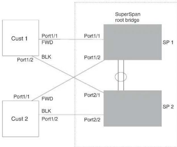
flowchart
graph TD
A["Cust 1"] -->|Port1/1 FWD BLK| B["SuperSpan root bridge"]
C["Cust 2"] -->|Port1/1 FWD BLK| B
B -->|Port1/1| D["SP 1"]
B -->|Port1/2| E["SP 2"]
B -->|Port2/1| E
B -->|Port2/2| E
In this example, the SP network contains two devices that are running SuperSpan. The SP is connected to two customer networks. Each customer network is running its own instance of STP. SuperSpan prevents Layer 2 loops in the traffic flow with each customer while at the same time isolating each customer's traffic and spanning tree from the traffic and spanning trees of other customers. For example, the SP devices provide loop prevention for Customer 1 while ensuring that Customer 1's traffic is never forwarded to Customer 2. In this example, customer 1 has two interfaces to the SP network, ports 1/1 and 1/2 connected to SP 1. The SP network behaves like a non-blocking hub. BPDUs are tunneled through the network. To prevent a Layer 2 loop, customer 1's port 1/2 enters the blocking state.
Customer ID
SuperSpan uses a SuperSpan customer ID to uniquely identify and forward traffic for each customer. You assign the customer ID as part of the SuperSpan configuration of the Brocade devices in the SP. In Table 34 on page 348, the spanning trees of customer 1 and customer 2 do not interfere with one another because the SP network isolates each customer's spanning tree based on the SuperSpan customer IDs in the traffic.
BPDU forwarding
When a Brocade device receives a customer's BPDU on a boundary interface, the device changes the destination MAC address of the BPDU from the bridge group address (01-80-c2-00-00-00) as follows.
The first byte (locally administered bit) is changed from 01 to 03, to indicate that the BPDU needs to be tunneled.
The fourth and fifth bytes are changed to the customer STP ID specified on the boundary interface.
For example, if the customer's STP ID is 1, the destination MAC address of the customer's BPDUs is changed to the following: 03-80-c2-00-01-00.
Each Brocade device that is configured for SuperSpan forwards the BPDU using the changed destination MAC address. At the other end of the tunnel, the Brocade device connected to the customer's network changes the destination MAC address back to the bridge group address (01-80-c2-00-00-00).
Preforwarding state
To ensure that the customer's network has time to converge at Layer 2 and prevent loops, the Brocade devices configured for SuperSpan use a special forwarding state, Preforwarding. The Preforwarding state occurs between the Learning and Forwarding states and by default lasts for five seconds. During the Preforwarding state, the Brocade device forwards tunneled BPDUs from customers only and does not forward data traffic. This ensures that the customer's network will detect the Layer 2 loop and block a port. The SP network remains unblocked. After the Preforwarding state, the Brocade ports change to the Forwarding state and forward data traffic as well as BPDUs.
The default length of the Preforwarding state is five seconds. You can change the length of the Preforwarding state to a value from 3 - 30 seconds.
Figure 35 shows an example of how the Preforwarding state is used.
FIGURE 35 SuperSpan preforwarding state

flowchart
graph TD
A["Cust 1"] -->|FWD| B["SuperSpan root bridge"]
A -->|BLK| C["SP 1"]
A -->|BPDU| D["SP 2"]
B -->|BPDU| E["Preforwarding"]
D -->|BPDU| F["Preforwarding"]
E --> G["Tunneled BPDU"]
F --> H["Tunneled BPDU"]
style A fill:#f9f,stroke:#333
style B fill:#ccc,stroke:#333
style C fill:#ccc,stroke:#333
style D fill:#ccc,stroke:#333
style E fill:#ccc,stroke:#333
style F fill:#ccc,stroke:#333
style G fill:#ccc,stroke:#333
style H fill:#ccc,stroke:#333
In this example, a customer has two links to the SP. Since the SP is running SuperSpan, the SP ports enter the Preforwarding state briefly to allow the customer ports connected to the SP to detect the Layer 2 loop and block one of the ports.
NOTE
If you add a new device to a network that is already running SuperSpan, you must enable SuperSpan on the new device, at least on the VLANs that will be tunneling the customer traffic. Otherwise, the new device does not use the Preforwarding state. This can cause temporary loops in the network.
Mixing single STP and multiple spanning trees
You can use SuperSpan in any of the following combinations:
- Customer and SP networks both use multiple spanning trees (a separate spanning tree in each VLAN).
- Customer uses multiple spanning trees but SP uses Single STP (all STP-enabled VLANs are in the same spanning tree).
- Customer uses Single STP but SP uses multiple spanning trees.
- Customer and SP networks both use Single STP.
- The following sections provide an example of each combination.
NOTE
All the combinations listed above are supported when the boundary ports joining the SP SuperSpan domain to the client spanning trees are untagged. For example, all these combinations are valid in super aggregated VLAN configurations. If the boundary ports are tagged, you cannot use Single STP in the client network in combination with multiple spanning trees in the SP SuperSpan domain.
The examples below are in super aggregated configuration scenarios.
Customer and SP use multiple spanning trees
Figure 36 shows an example of SuperSpan where both the customer network and the SP network use multiple spanning trees (a separate spanning tree in each port-based VLAN).
FIGURE 36 Customer and SP using Multiple Spanning Trees

flowchart
graph TD
A["Customer Region"] -->|1/1| B["R 10"]
A -->|3/1| C["R 20"]
B -->|2/1| D["R 100"]
C -->|2/1| E["R 200"]
D -->|2/2| F["Provider Region"]
E -->|2/2| G["Provider Region"]
H["Root bridge for VLAN xx"] --> I["R xx"]
style A fill:#f9f,stroke:#333
style B fill:#ccf,stroke:#333
style C fill:#ccf,stroke:#333
style D fill:#ccf,stroke:#333
style E fill:#ccf,stroke:#333
style F fill:#ccf,stroke:#333
style G fill:#ccf,stroke:#333
note right of A: 'tagged to multiple vlan'
note left of H: 'stp-boundary untagged to vlan 100 (Super Aggregated VLAN)'
Both the customer and SP regions are running multiple spanning trees (one per port-based VLAN) in the Layer 2 switched network. The customer network contains VLANs 10 and 20 while the SP network contains VLANs 100 and 200. Customer traffic from VLAN 10 and VLAN 20 is aggregated by VLAN 100 in the SP since the boundary ports, 2/1 on R100 and R200, are untagged members of VLAN 100. By adjusting the bridge priority on VLANs 10 and 20, the customer can select a different root bridge for each spanning tree running in the customer network.
In the above example, STP in VLAN 10 will select R10 as the root bridge and make 1/1 on R10 forwarding while blocking port 3/1 on R20. The opposite occurs for STP in VLAN 20. As a result, both links connecting the customer and SP regions are fully utilized and serve as backup links at the same time, providing loop-free, non-blocking connectivity. In the SP network, multiple STP instances are running (one for VLAN 100 and one for VLAN 200) to ensure loop-free, non-blocking connectivity in each VLAN.
SuperSPAN boundaries are configured at port 2/1 of R100 and R200. Since the customer's traffic will be aggregated into VLAN 100 at the SP, the SP network appears to the customer to be a loop-free non-blocking hub to the customer network when port 2/2 on R200 is blocked by STP in VLAN 100.
Customer uses multiple spanning trees but SP uses single STP
Figure 37 shows an example of SuperSpan where the customer network uses multiple spanning trees while the SP network uses Single STP.
FIGURE 37 Customer using Multiple Spanning Trees and SP using single STP

flowchart
graph TD
A["Customer Region"] -->|1/1| B["R₁₀"]
A -->|3/1| C["R₂₀"]
B -->|2/1| D["Provider Region"]
C -->|2/1| D
B -->|2/2| E["R single span"]
C -->|2/2| E
D -->|2/2| F["Provider Region"]
style A fill:#f9f,stroke:#333
style B fill:#ccf,stroke:#333
style C fill:#ccf,stroke:#333
style D fill:#ccf,stroke:#333
style E fill:#ccf,stroke:#333
style F fill:#ccf,stroke:#333
note right of A: "tagged to multiple vlan"
note right of F: "stp-boundary untagged to vlan 100 (Super Aggregated VLAN)"
note right of B: "Root bridge for VLAN xx"
Customer traffic from different VLANs is maintained by different spanning trees, while the SP network is maintained by a single spanning tree. The SP can still use multiple VLANs at the core to separate traffic from different customers. However, all VLANs will have the same network topology because they are all calculated by the single spanning tree. The loop-free, non-blocking network acts like a hub for the customer network, with boundary ports 2/1 on each device being untagged members of VLAN 100.
Traffic from all VLANs in the customer network will be aggregated through VLAN 100 at the SP. This setup leaves the customer network's switching pattern virtually unchanged from the scenario in "Customer and SP use multiple spanning trees" on page 350, since the SP network still is perceived as a virtual hub, and maintenance of the hub's loop-free topology is transparent to the customer network.
Customer uses single STP but SP uses multiple spanning trees
Figure 38 shows an example of SuperSpan where the customer network uses Single STP while the SP uses multiple spanning trees.
FIGURE 38 Customer using single STP and SP using Multiple Spanning Trees

flowchart
graph TD
A["Customer Region"] --> B["R single span"]
A --> C["R 200"]
B -->|1/1| D["R 100"]
B -->|3/1| C
D -->|2/1| E["Provider Region"]
D -->|2/2| F["Provider Region"]
C -->|2/1| G["Provider Region"]
C -->|2/2| H["Provider Region"]
style A fill:#f9f,stroke:#333
style B fill:#ccf,stroke:#333
style C fill:#ccf,stroke:#333
style D fill:#cfc,stroke:#333
style E fill:#fcc,stroke:#333
style F fill:#fcc,stroke:#333
style G fill:#fcc,stroke:#333
style H fill:#fcc,stroke:#333
In this setup, the customer network is running a single spanning tree for VLANs 10 and 20. The traffic from VLAN 10 and 20 will be carried, or aggregated by VLAN 100 at the SP's network. The main difference between this scenario and the previous two scenarios is that all traffic at the customer's network now follows the same path, having the same STP root bridge in all VLANs. Therefore, the customer network will not have the ability to maximize network utilization on all its links. On the other hand, loop-free, non-blocking topology is still separately maintained by the customer network's single spanning tree and the SP's per-VLAN spanning tree on VLAN 100.
Customer and SP use single STP
Figure 39 shows an example of SuperSpan where the customer network and SP both use Single STP.
FIGURE 39 Customer and SP using single STP

flowchart
graph TD
A["Customer Region"] -->|tagged to multiple vlan| B["R single span"]
A -->|stp-boundary untagged to vlan 100| C["Provider Region"]
B -->|1/1| D["R single span"]
B -->|3/1| E["Provider Region"]
C -->|2/1| F["Provider Region"]
C -->|2/2| G["Provider Region"]
style A fill:#f9f,stroke:#333
style B fill:#ccf,stroke:#333
style C fill:#ccf,stroke:#333
style D fill:#cfc,stroke:#333
style E fill:#cfc,stroke:#333
style F fill:#cfc,stroke:#333
style G fill:#cfc,stroke:#333
In this setup, both the customer and SP networks are running a single spanning tree at Layer 2. The traffic from VLAN 10 and 20 will be carried, or aggregated by VLAN 100 at the SP network as in the previous scenario. Loop-free, non-blocking topology is still separately maintained by the customer's single spanning tree and the SP's single spanning tree.
Configuring SuperSpan
To configure a device for SuperSpan:
- Configure each interface on the device that is connected to customer equipment as a boundary interface. This step enables the interface to convert the destination MAC address in the customer's BPDUs.
The software requires you to specify a SuperSpan customer ID when configuring the boundary interface. Use an ID from 1 – 65535. The customer ID uniquely identifies the customer. Use the same customer ID for each SP interface with the same customer. When tunneling BPDUs through the Brocade network, the devices use the customer ID to ensure that BPDUs are forwarded only to the customer's devices, and not to other customers' devices.
- Globally enable SuperSpan. This step enables the Preforwarding state.
Configuring a boundary interface
To configure the boundary interfaces on SP 1 in, enter the following commands.
BigIron RX(config)# interface 1/1
BigIron RX(config-if-e1000-1/1)# stp-boundary 1
BigIron RX(config)# interface 1/2
BigIron RX(config-if-e1000-1/2)# stp-boundary 2
These commands configure two interfaces on the Brocade device as SuperSpan boundary interfaces. Interface 1/1 is a boundary interface with customer 1. Interface 1/2 is a boundary interface with customer 2. Each boundary interface is associated with a number, which is the SuperSpan ID. The SuperSpan ID identifies the instance of SuperSpan you are associating with the interface. Use the same SuperSpan ID for each boundary interface with the same customer. Use a different SuperSpan ID for each customer. For example, use SuperSpan ID 1 for all the boundary interfaces with customer 1 and use SuperSpan ID 2 for all boundary interfaces with customer 2.
Syntax: [no] stp-boundary
The
To configure the boundary interfaces on SP 2 in Figure 34, enter the following commands.
BigIron RX(config)# interface 2/1
BigIron RX(config-if-e1000-2/1)# stp-boundary 1
BigIron RX(config)# interface 2/2
BigIron RX(config-if-e1000-2/2)# stp-boundary 2
Enabling SuperSpan
After you configure the SuperSpan boundary interfaces, enable SuperSpan. You can enable SuperSpan globally or on an individual VLAN level. If you enable the feature globally, the feature is enabled on all VLANs.
NOTE
If you enable the feature globally, then create a new VLAN, the new VLAN inherits the global SuperSpan state. For example, if SuperSpan is globally enabled when you create a VLAN, SuperSpan also is enabled in the new VLAN.
You also can change the length of the Preforwarding state to a value from 3 - 30 seconds. The default is 5 seconds.
To globally enable SuperSpan, enter the following command.
BigIron RX(config)# super-span-global
Syntax: [no] super-span-global [preforward-delay
The
SuperSpan is enabled in all VLANs on the device. To disable SuperSpan in an individual VLAN, enter commands such as the following.
BigIron RX(config)# vlan 10
BigIron RX(config-vlan-10)# no super-span
Syntax: [no] super-span
Displaying SuperSpan information
To display the boundary interface configuration and BPDU statistics, enter the following command.
BigIron RX(config)# show super-span
CID 1 Boundary Ports:
| Port | C-BPDU Rxed | C-BPDU Txed | T-BPDU Rxed | T-BPDU Txed |
| 1/1 | 1 | 0 | 0 | 0 |
| 1/2 | 0 | 0 | 0 | 0 |
| Total | 1 | 0 | 0 | 0 |
CID 2 Boundary Ports:
| Port | C-BPDU | C-BPDU | T-BPDU | T-BPDU |
| Rxed | Txed | Rxed | Txed | |
| 2/1 | 0 | 0 | 3 | 0 |
| 2/2 | 0 | 0 | 0 | 0 |
| Total | 0 | 0 | 3 | 0 |
In this example, the device has two SuperSpan customer IDs.
Syntax: show superspan [cid
The cid
This command shows the following information.
TABLE 78 CLI display of SuperSpan customer ID information
This field... Displays...
| CID The SuperSpan customer ID number. |
| Port The boundary port number. |
| C-BPDU Rxed The number of BPDUs received from the client spanning tree. |
| C-BPDU Txed The number of BPDUs sent to the client spanning tree. |
| T-BPDU Rxed The number of BPDUs received from the SuperSpan tunnel. |
| T-BPDU Txed The number of BPDUs sent to the SuperSpan tunnel. |
To display general STP information, refer to "Displaying STP information" on page 332.
Overview of Rapid Spanning Tree Protocol
RSTP provides rapid convergence and takes advantage of point-to point wiring of the spanning tree. Failure in one forwarding path does not affect other forwarding paths. RSTP improves the operation of the spanning tree while maintaining backward compatibility.
NOTE
The total number of supported STP, RSTP, or MSTP indices is 128.
Bridges and bridge port roles
A bridge in an RSTP rapid spanning tree topology is assigned as the root bridge if it has the highest priority (lowest bridge identifier) in the topology. Other bridges are referred to as non-root bridges.
Unique roles are assigned to ports on the root and non-root bridges. Role assignments are based on the following information contained in the BPDU (RSTp packet):
- Root bridge ID
- Path cost value
• Transmitting bridge ID - Designated port ID
RSTP algorithm uses this information to determine if the RST BPDU received by a port is superior to the RST BPDU that the port transmits. The two values are compared in the order as given above, starting with the Root bridge ID. The RST BPDU with a lower value is considered superior. The superiority and inferiority of the RST BPDU is used to assign a role to a port.
If the value of the received RST BPDU is the same as that of the transmitted RST BPDU, then the port ID in the RST BPDUs are compared. The RST BPDU with the lower port ID is superior. Port roles are then calculated appropriately.
The port's role is included in the BPDU that it transmits. The BPDU transmitted by an RSTP port is referred to as an RST BPDU, while it is operating in RSTP mode.
Ports can have one of the following roles:
- Root – Provides the lowest cost path to the root bridge from a specific bridge
- Designated – Provides the lowest cost path to the root bridge from a LAN to which it is connected
- Alternate – Provides an alternate path to the root bridge when the root port goes down
- Backup – Provides a backup to the LAN when the Designated port goes down
- Disabled – Has no role in the topology
Assignment of port roles
At system start-up, all RSTP-enabled bridge ports assume a Designated role. Once start-up is complete, RSTP algorithm calculates the superiority or inferiority of the RST BPDU that is received and transmitted on a port.
On a root bridge, each port is assigned a Designated port role, except for ports on the same bridge that are physically connected together. In these type of ports, the port that receives the superior RST BPDU becomes the Backup port, while the other port becomes the Designated port.
On non-root bridges, ports are assigned as follows:
- The port that receives the RST BPDU with the lowest path cost from the root bridge becomes the Root port.
- If two ports on the same bridge are physically connected, the port that receives the superior RST BPDU becomes the Backup port, while the other port becomes the Designated port.
- If a non-root bridge already has a Root port, then the port that receives an RST BPDU that is superior to those it can transmit becomes the Alternate port.
- If the RST BPDU that a port receives is inferior to the RST BPDUs it transmits, then the port becomes a Designated port.
- If the port is down or if RSTP is disabled on the port, that port is given the role of Disabled port. Disabled ports have no role in the topology. However, if RSTP is enabled on a port with a link down and the link of that port comes up, then that port assumes one of the following port roles: Root, Designated, Alternate, or Backup.
The following example (Figure 40) explains role assignments in a simple RSTP topology.
NOTE
All examples in this document assume that all ports in the illustrated topologies are point-to-point links and are homogeneous (they have the same path cost value) unless otherwise specified.
The topology in Figure 40 contains four bridges. Switch 1 is the root bridge since it has the lowest bridge priority. Switch 2 through Switch 4 are non-root bridges.
FIGURE 40 Simple RSTP topology
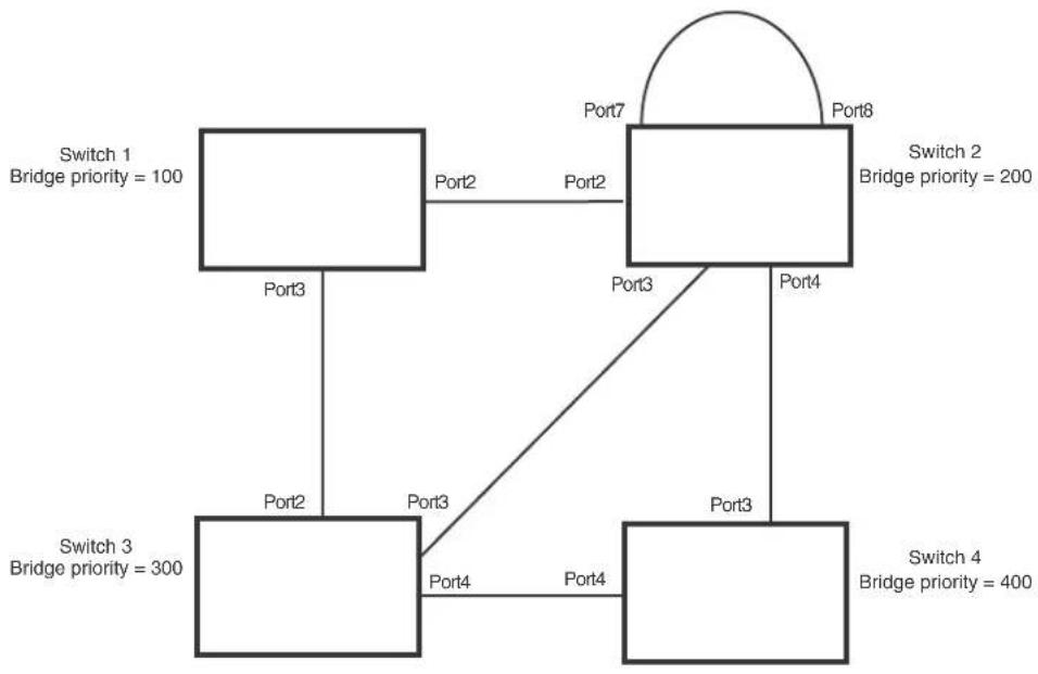
flowchart
graph TD
A["Switch 1\nBridge priority = 100"] -->|Port2| B["Switch 2\nBridge priority = 200"]
A -->|Port3| C["Switch 3\nBridge priority = 300"]
B -->|Port4| D["Switch 4\nBridge priority = 400"]
C -->|Port2| A
B -->|Port7| B
B -->|Port8| A
C -->|Port3| A
C -->|Port4| B
Ports on Switch 1
All ports on Switch 1, the root bridge, are assigned Designated port roles.
Ports on Switch 2
Port2 on Switch 2 directly connects to the root bridge; therefore, Port2 is the Root port.
Switch 2's bridge priority value is superior to that of Switch 3 and Switch 4; therefore, the ports on Switch 2 that connect to Switch 3 and Switch 4 are given the Designated port role.
Furthermore, Port7 and Port8 on Switch 2 are physically connected. The RST BPDUs transmitted by Port7 are superior to those Port8 transmits. Therefore, Switch 2 is the Backup port and Port7 is the Designated port.
Ports on Switch 3
Port2 on Switch 3 directly connects to the Designated port on the root bridge; therefore, it assumes the Root port role.
The root path cost of the RST BPDUs received on Port4/Switch 3 is inferior to the RST BPDUs transmitted by the port; therefore, Port4/Switch 3 becomes the Designated port.
Similarly, Switch 3 has a bridge priority value inferior to Switch 2. Port3 on Switch 3 connects to Port 3 on Switch 2. This port will be given the Alternate port role, since a Root port is already established on this bridge.
Ports Switch 4
Switch 4 is not directly connected to the root bridge. It has two ports with superior incoming RST BPDUs from two separate LANs: Port3 and Port4. The RST BPDUs received on Port3 are superior to the RST BPDUs received on port 4; therefore, Port3 becomes the Root port and Port4 becomes the Alternate port.
Brocade's implementation of RSTP allows ports that are configured as Edge ports to be present in an RSTP topology. (Figure 41). Edge ports are ports of a bridge that connect to workstations or computers. Edge ports do not register any incoming BPDU activities.
Edge ports assume Designated port roles. Port flapping does not cause any topology change events on Edge ports since RSTP does not consider Edge ports in the spanning tree calculations.
FIGURE 41 Topology with edge ports

flowchart
graph TD
A["Switch 1\nBridge priority = 600"] -->|Port3| B["Switch 2\nBridge priority = 1000"]
A -->|Port2| C["Switch 3\nBridge priority = 2000"]
B -->|Port3| C
C -->|Port5\nEdge Port| D["Computer"]
B -->|Port2\nPort2| A
B -->|Port3| C
However, if any incoming RST BPDU is received from a previously configured Edge port, RSTP automatically makes the port as a non-edge port. This is extremely important to ensure a loop free Layer 2 operation since a non-edge port is part of the active RSTP topology.
The bridge detection state module can auto-detect an Edge port and a non-edge port. An administrator can also configure a port to be an Edge port. It is recommended that Edge ports are configured explicitly to take advantage of the Edge port feature, instead of allowing the protocol to auto-detect them.
Point-to-point ports
To take advantage of the RSTP features, ports on an RSTP topology should be explicitly configured as point-to-point links. Shared media should not be configured as point-to-point links.
NOTE
Configuring shared media or non-point-to-point links as point-to-point links could lead to Layer 2 loops.
The topology in Figure 42 is an example of shared media that should not be configured as point-to-point links. In Figure 42, a port on a bridge communicates or is connected to at least two ports.
FIGURE 42 Example of shared media

flowchart
graph TD
A[" "] --> B[" "]
C[" "] --> D[" "]
E[" "] --> F[" "]
G[" "] --> H[" "]
Bridge port states
Ports roles can have one of the following states:
- Forwarding – RSTP is allowing the port to send and receive all packets.
- Discarding – RSTP has blocked data traffic on this port to prevent a loop. The device or VLAN can reach the root bridge using another port, whose state is forwarding. When a port is in this state, the port does not transmit or receive data frames, but the port does continue to receive RST BPDUs. This state corresponds to the listening and blocking states of 802.1D.
- Learning – RSTP is allowing MAC address entries to be added to the filtering database but does not permit forwarding of data frames. The device can learn the MAC addresses of frames that the port receives during this state and make corresponding entries in the MAC table.
- Disabled – The port is not participating in RSTP. This can occur when the port is disconnected or RSTP is administratively disabled on the port.
A port on a non-root bridge with the role of Root port is always in a forwarding state. If another port on that bridge assumes the Root port role, then the old Root port moves into a discarding state as it assumes another port role.
A port on a non-root bridge with a Designated role starts in the discarding state. When that port becomes elected to the Root port role, RSTP quickly places it into a forwarding state. However, if the Designated port is an Edge port, then the port starts and stays in a forwarding state and it cannot be elected as a Root port.
A port with an Alternate or Backup role is always in a discarding state. If the port's role changes to Designated, then the port changes into a forwarding state.
If a port on one bridge has a Designated role and that port is connected to a port on another bridge that has an Alternate or Backup role, the port with a Designated role cannot be given a Root port role until two instances of the forward delay timer expires on that port.
Edge port and non-edge port states
As soon as a port is configured as an Edge port, it goes into a forwarding state instantly (in less than 100 msec).
When the link to a port comes up and RSTP detects that the port is an Edge port, that port instantly goes into a forwarding state.
If RSTP detects that port as a non-edge port, the port goes into a forwarding state within four seconds of link up or after two hello timer expires on the port.
Changes to port roles and states
To achieve convergence in a topology, a port's role and state changes as it receives and transmits new RST BPDUs. Changes in a port's role and state constitute a topology change. Besides the superiority and inferiority of the RST BPDU, bridge-wide and per-port state machines are used to determine a port's role as well as a port's state. Port state machines also determine when port role and state changes occur.
State machines
The bridge uses the Port Role Selection state machine to determine if port role changes are required on the bridge. This state machine performs a computation when one of the following events occur:
- New information is received on any port on the bridge
• The timer expires for the current information on a port on the bridge
Each port uses the following state machines:
- Port Information – This state machine keeps track of spanning-tree information currently used by the port. It records the origin of the information and ages out any information that was derived from an incoming BPDU.
- Port Role Transition – This state machine keeps track of the current port role and transitions the port to the appropriate role when required. It moves the Root port and the Designated port into forwarding states and moves the Alternate and Backup ports into discarding states.
- Port Transmit – This state machine is responsible for BPDU transmission. It checks to ensure only the maximum number of BPDUs per hello interval are sent every second. Based on what mode it is operating in, it sends out either legacy BPDUs or RST BPDUs. In this document legacy BPDUs are also referred to as STP BPDUs.
- Port Protocol Migration – This state machine deals with compatibility with 802.1D bridges. When a legacy BPDU is detected on a port, this state machine configures the port to transmit and receive legacy BPDUs and operate in the legacy mode.
- Topology Change – This state machine detects, generates, and propagates topology change notifications. It acknowledges Topology Change Notice (TCN) messages when operating in 802.1D mode. It also flushes the MAC table when a topology change event takes place.
- Port State Transition – This state machine transitions the port to a discarding, learning, or forwarding state and performs any necessary processing associated with the state changes.
- Port Timers – This state machine is responsible for triggering any of the state machines described above, based on expiration of specific port timers.
In contrast to the 802.1D standard, the RSTP standard does not have any bridge specific timers. All timers in the CLI are applied on a per-port basis, even though they are configured under bridge parameters.
RSTP state machines attempt to quickly place the ports into either a forwarding or discarding state. Root ports are quickly placed in forwarding state when both of the following events occur:
- It is assigned to be the Root port.
- It receives an RST BPDU with a proposal flag from a Designated port. The proposal flag is sent by ports with a Designated role when they are ready to move into a forwarding state.
When a the role of Root port is given to another port, the old Root port is instructed to reroot. The old Root port goes into a discarding state and negotiates with its peer port for a new role and a new state. A peer port is the port on the other bridge to which the port is connected. For example, in Figure 43, Port1 of Switch 200 is the peer port of Port2 of Switch 100.
A port with a Designated role is quickly placed into a forwarding state if one of the following occurs:
- The Designated port receives an RST BPDU that contains an agreement flag from a Root port
• The Designated port is an Edge port
However, a Designated port that is attached to an Alternate port or a Backup port must wait until the forward delay timer expires twice on that port while it is still in a Designated role, before it can proceed to the forwarding state.
Backup ports are quickly placed into discarding states.
Alternate ports are quickly placed into discarding states.
A port operating in RSTP mode may enter a learning state to allow MAC address entries to be added to the filtering database; however, this state is transient and lasts only a few milliseconds, if the port is operating in RSTP mode and if the port meets the conditions for rapid transition.
Handshake mechanisms
To rapidly transition a Designated or Root port into a forwarding state, the Port Role Transition state machine uses handshake mechanisms to ensure loop free operations. It uses one type of handshake if no Root port has been assigned on a bridge, and another type if a Root port has already been assigned.
Handshake when no root port is elected
If a Root port has not been assigned on a bridge, RSTP uses the Proposing -> Proposed -> Sync -> Synced -> Agreed handshake:
- Proposing – The Designated port on the root bridge sends an RST BPDU packet to its peer port that contains a proposal flag. The proposal flag is a signal that indicates that the Designated port is ready to put itself in a forwarding state (Figure 43). The Designated port continues to send this flag in its RST BPDU until it is placed in a forwarding state (Figure 46) or is forced to operate in 802.1D mode. (Refer to “Compatibility of RSTP with 802.1D” on page 384)
-
Proposed – When a port receives an RST BPDU with a proposal flag from the Designated port on its point-to-point link, it asserts the Proposed signal and one of the following occurs (Figure 43):
-
If the RST BPDU that the port receives is superior to what it can transmit, the port assumes the role of a Root port. (Refer to “Bridges and bridge port roles” on page 357.)
- If the RST BPDU that the port receives is inferior to what it can transmit, then the port is given the role of Designated port.
NOTE
Proposed will never be asserted if the port is connected on a shared media link.
In Figure 43, Port3/Switch 200 is elected as the Root port
FIGURE 43 Proposing and proposed stage

flowchart
graph TD
A["Switch 100 Root Bridge"] -->|RST BPDU sent with a Proposal flag| B["Switch 200"]
A -->|Port2 Designated port Proposing| C["Switch 200"]
B -->|Port1 Root port Proposed| D["Switch 200"]
B -->|Port2 Port3| E["Switch 300"]
B -->|Port3 Port3| F["Switch 400"]
- Sync – Once the Root port is elected, it sets a sync signal on all the ports on the bridge. The signal tells the ports to synchronize their roles and states (Figure 44). Ports that are non-edge ports with a role of Designated port change into a discarding state. These ports have to negotiate with their peer ports to establish their new roles and states.
FIGURE 44 Sync stage
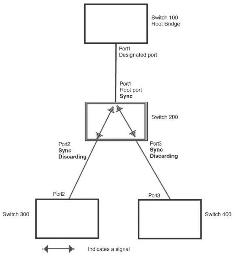
flowchart
graph TD
A["Switch 100 Root Bridge"] -->|Port1 Designated port| B["Switch 200"]
B -->|Port2 Sync Discarding| C["Switch 300"]
B -->|Port3 Sync Discarding| D["Switch 400"]
B -->|Indicates a signal| E["Ground"]
B -->|Sync| F["Node"]
- Synced – Once the Designated port changes into a discarding state, it asserts a synced signal. Immediately, Alternate ports and Backup ports are synced. The Root port monitors the synced signals from all the bridge ports. Once all bridge ports asserts a synced signal, the Root port asserts its own synced signal (Figure 45).
FIGURE 45 Synced stage

flowchart
graph TD
A["Switch 100 Root Bridge"] -->|Port1 Designated port| B["Central Node"]
B -->|Port2 Synced Discarding| C["Switch 300"]
B -->|Port3 Synced Discarding| D["Switch 400"]
B -->|Indicates a signal| E["Signal Line"]
B --> F["Node 1"]
B --> G["Node 2"]
B --> H["Node 3"]
- Agreed – The Root port sends back an RST BPDU containing an agreed flag to its peer Designated port and moves into the forwarding state. When the peer Designated port receives the RST BPDU, it rapidly transitions into a forwarding state.
FIGURE 46 Agree stage

flowchart
graph TD
A["Switch 100 Root Bridge"] -->|Port1 Designated port Forwarding| B["Switch 200"]
B -->|Port2 Synced Discarding| C["Switch 300"]
B -->|Port3 Synced Discarding| D["Switch 400"]
B -->|RST BPDU sent with an Agreed flag| A
style A fill:#f9f,stroke:#333
style B fill:#ccf,stroke:#333
style C fill:#cfc,stroke:#333
style D fill:#fcc,stroke:#333
At this point, the handshake mechanism is complete between Switch 100, the root bridge, and Switch 200.
Switch 200 updates the information on the Switch 200's Designated ports (Port2 and Port3) and identifies the new root bridge. The Designated ports send RST BPDUs, containing proposal flags, to their downstream bridges, without waiting for the hello timers to expire on them. This process starts the handshake with the downstream bridges.
For example, Port2/Switch 200 sends an RST BPDU to Port2/Switch 300 that contains a proposal flag. Port2/Switch 300 asserts a proposed signal. Ports in Switch 300 then set sync signals on the ports to synchronize and negotiate their roles and states. Then the ports assert a synced signal and when the Root port in Switch 300 asserts it is synced signal, it sends an RST BPDU to Switch 200 with an agreed flag.
This handshake is repeated between Switch 200 and Switch 400 until all Designated and Root ports are in forwarding states.
Handshake when a root port has been elected
If a non-root bridge already has a Root port, RSTP uses a different type of handshake. For example, in Figure 47, a new root bridge is added to the topology.
FIGURE 47 Addition of a new root bridge
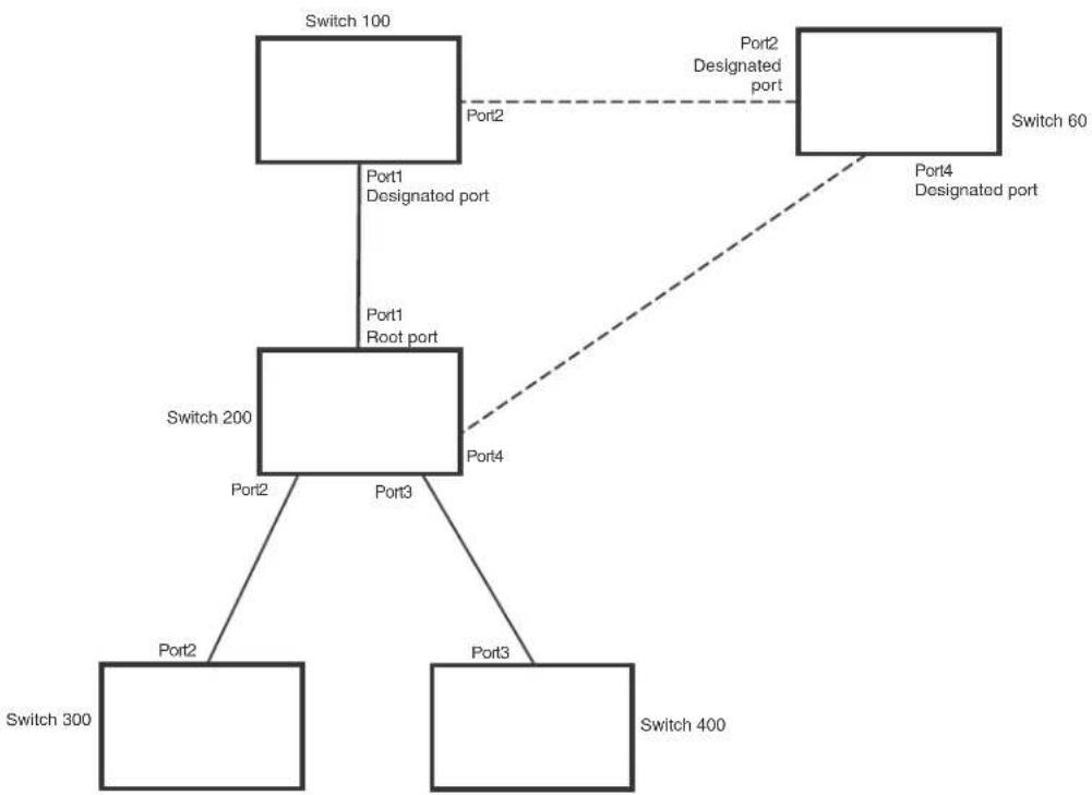
flowchart
graph TD
A["Switch 100"] -->|Port1 Designated port| B["Switch 200"]
B -->|Port2| C["Switch 60"]
B -->|Port3 Root port| D["Switch 300"]
B -->|Port4| E["Switch 400"]
C -.->|Port2 Designated port| B
D -.->|Port3 Designated port| B
The handshake that occurs between Switch 60 and Switch 100 follows the one described in the previous section (“Handshake when no root port is elected” on page 363). The former root bridge becomes a non-root bridge and establishes a Root port (Figure 48).
However, since Switch 200 already had a Root port in a forwarding state, RSTP uses the Proposing -> Proposed -> Sync and Reroot -> Sync and Rerooted -> Rerooted and Synced -> Agreed handshake:
- Proposing and Proposed – The Designated port on the new root bridge (Port4/Switch 60) sends an RST BPDU that contains a proposing signal to Port4/Switch 200 to inform the port that it is ready to put itself in a forwarding state (Figure 48). RSTP algorithm determines that the RST BPDU that Port4/Switch 200 received is superior to what it can generate, so Port4/Switch 200 assumes a Root port role.
FIGURE 48 New root bridge sending a proposal flag
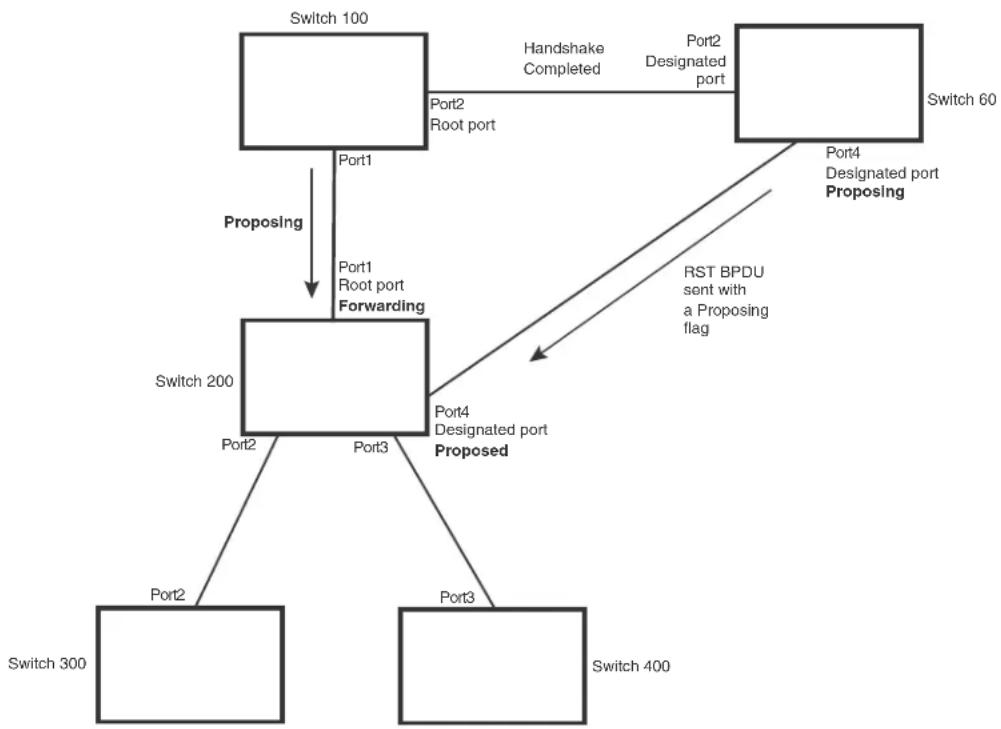
flowchart
graph TD
A["Switch 100"] -->|Proposing| B["Switch 200"]
A -->|Proposing| C["Switch 60"]
B -->|Proposing| D["Switch 300"]
B -->|Proposing| E["Switch 400"]
B -->|Proposing| F["Port1 Root port Forwarding"]
F -->|Proposing| B
F -->|Proposing| G["Port2 Root port"]
G -->|Proposing| H["Switch 100"]
F -->|Proposing| I["Port3"]
I -->|Proposing| J["Switch 200"]
F -->|Proposing| K["Port4 Designated port"]
K -->|Proposing| L["Switch 60"]
K -->|Proposing| M["Port4 Designated port Proposing"]
M --> N["RST BPDU sent with a Proposing flag"]
N --> F
N --> I
N --> J
N --> K
style A fill:#f9f,stroke:#333
style B fill:#ccf,stroke:#333
style C fill:#cfc,stroke:#333
style D fill:#fcc,stroke:#333
style E fill:#cff,stroke:#333
style F fill:#ffc,stroke:#333
style G fill:#fcc,stroke:#333
style H fill:#ffc,stroke:#333
style I fill:#fcc,stroke:#333
style J fill:#fcc,stroke:#333
style K fill:#fcc,stroke:#333
style L fill:#fcc,stroke:#333
style M fill:#fcc,stroke:#333
- Sync and Reroot – The Root port then asserts a sync and a reroot signal on all the ports on the bridge. The signal tells the ports that a new Root port has been assigned and they are to renegotiate their new roles and states. The other ports on the bridge assert their sync and reroot signals. Information about the old Root port is discarded from all ports. Designated ports change into discarding states (Figure 49).
FIGURE 49 Sync and reroot

flowchart
graph TD
A["Switch 100"] -->|Port1| B["Switch 200"]
A -->|Port2 Root port| C["Switch 60"]
A -->|Port2 Root port| D["Switch 300"]
A -->|Port2 Root port| E["Switch 400"]
B -->|Port3 Sync Reroot Discarding| F["Indicates a signal"]
B -->|Port4 Root port Sync Reroot Discarding| G["Switch 60"]
B -->|Port3 Sync Reroot Discarding| H["Switch 300"]
B -->|Port4 Root port Sync Reroot Discarding| I["Switch 400"]
style A fill:#f9f,stroke:#333
style B fill:#ccf,stroke:#333
style C fill:#cfc,stroke:#333
style D fill:#fcc,stroke:#333
style E fill:#cff,stroke:#333
style F fill:#ffc,stroke:#333
style G fill:#ffc,stroke:#333
style H fill:#ffc,stroke:#333
style I fill:#ffc,stroke:#333
- Sync and Rerooted – When the ports on Switch 200 have completed the reroot phase, they assert their rerooted signals and continue to assert their sync signals as they continue in their discarding states. They also continue to negotiate their roles and states with their peer ports (Figure 50).
FIGURE 50 Sync and rerooted

flowchart
graph TD
A["Switch 100"] -->|Port1| B["Switch 200"]
A -->|Port2, Port4, Port2, Port4, Port4, Port4, Port4, Port4, Port4, Port4, Port4, Port4, Port4, Port4, Port4, Port4, Port4, Port4, Port4, Port4, Port4, Port4, Port4, Port4, Port4, Port4, Port4, Port4, Port4, Port4, Port4, Port4, Port4, Port4, Port4, Port4, Port4]
B -->|Proposing| C["Switch 300"]
B -->|Proposing| D["Switch 400"]
B -->|Proposing| E["Port2, Sync Rerooted Discarding"]
B -->|Proposing| F["Port3, Sync Rerooted Discarding"]
B -->|Proposing| G["Port4, Root port Sync Rerooted Discarding"]
B -->|Proposing| H["Port2, Root port"]
B -->|Proposing| I["Port2, Root port"]

Indicates an 802.1W signal controlled by the current Root port
- Synced and Agree – When all the ports on the bridge assert their synced signals, the new Root port asserts its own synced signal and sends an RST BPDU to Port4/Switch 60 that contains an agreed flag (Figure 50). The Root port also moves into a forwarding state.
FIGURE 51 Rerooted, synced, and agreed
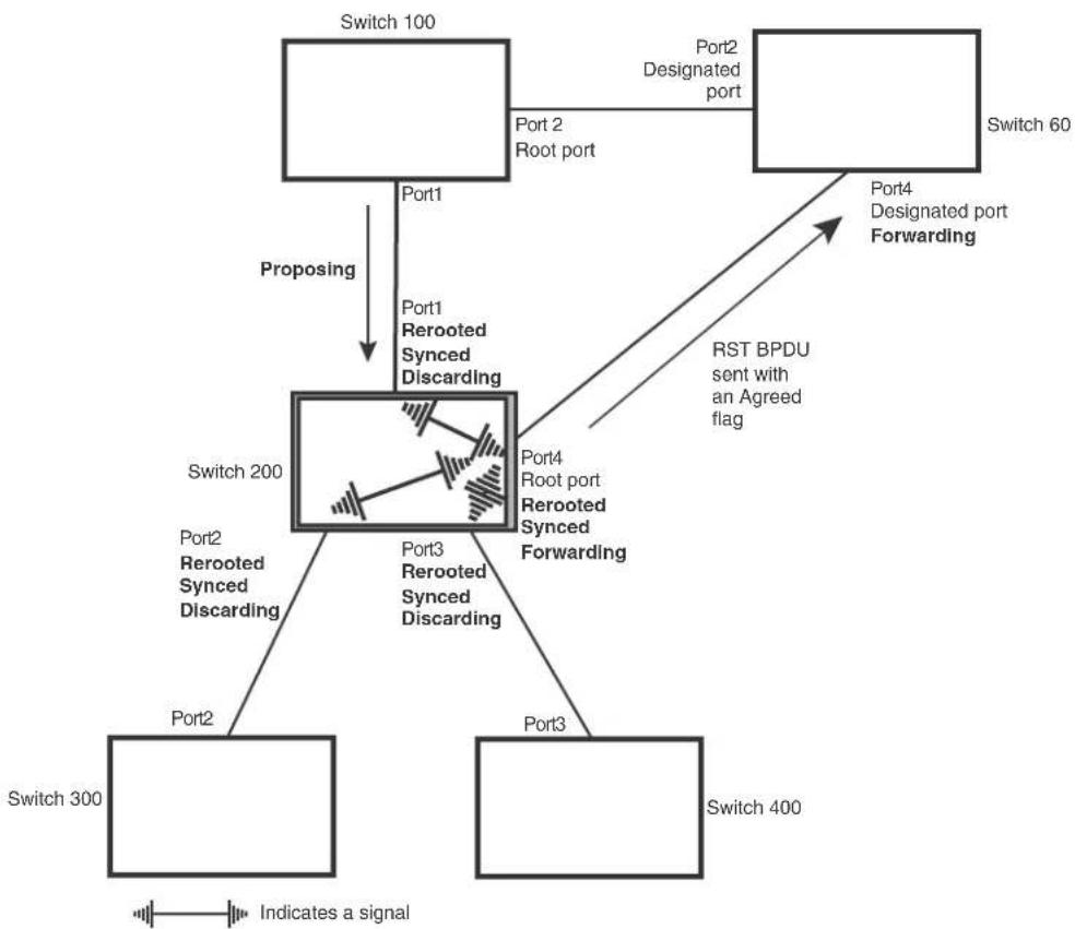
flowchart
graph TD
A["Switch 100"] -->|Port1| B["Switch 200"]
A -->|Port2 Root port| C["Switch 60"]
B -->|Port3 Rerooted Synced Discarding| D["Switch 300"]
B -->|Port4 Root port Rerooted Synced Forwarding| E["Switch 400"]
B -->|Port1 Rerooted Synced Discarding| F["Switch 200"]
G["Port2"] -->|Proposing| B
H["Port3"] -->|Proposing| B
I["Port4"] -->|RST BPDU sent with an Agreed flag| B
J["Indicates a signal"] --> K["Signal Signal"]
The old Root port on Switch 200 becomes an Alternate Port (Figure 52). Other ports on that bridge are elected to appropriate roles.
The Designated port on Switch 60 goes into a forwarding state once it receives the RST BPDU with the agreed flag.
FIGURE 52 Handshake completed after election of new root port
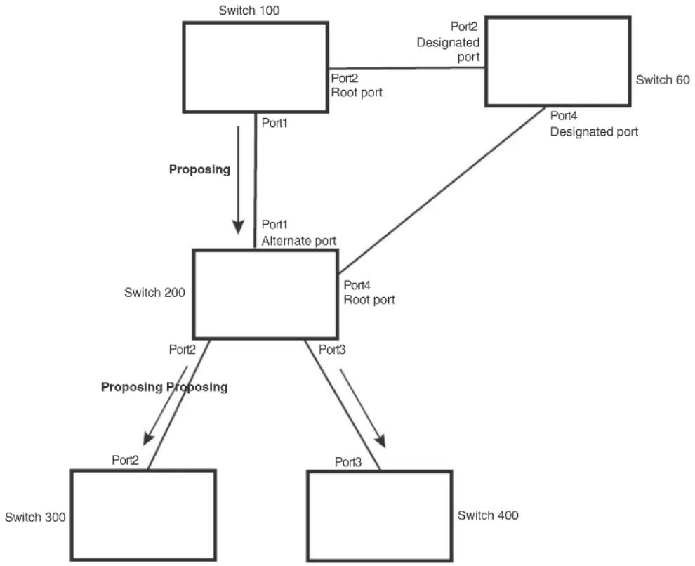
flowchart
graph TD
A["Switch 100"] -->|Port1| B["Switch 200"]
A -->|Port2, Port2, Port2, Port2, Port2, Port2, Port2, Port2, Port2, Port2, Port2, Port2, Port2, Port2, Port2, Port2, Port2, Port2, Port2, Port2, Port2, Port2, Port2, Port2, Port2, Port2, Port2, Port2, Port2, Port2, Port2, Port2, Port2, Port2, Port3]
B -->|Port1, Port1, Port1, Port1, Port1, Port1, Port1, Port1, Port1, Port1, Port1, Port1, Port1, Port1, Port1, Port1, Port1, Port1, Port1, Port1, Port1, Port1, Port1, Port1, Port1, Port1, Port1, Port1, Port1, Port1, Port1, Port1, Port1, Port1, Port3]
B -->|Port4, Port4, Port4, Port4, Port4, Port4, Port4, Port4, Port4, Port4, Port4, Port4, Port4, Port4, Port4, Port4, Port4, Port4, Port4, Port4, Port4| B
B -->|Port3| C["Switch 300"]
B -->|Port3| D["Switch 400"]
B -->|Port2| E["Switch 300"]
B -->|Port2| F["Switch 400"]
Recall that Switch 200 sent the agreed flag to Port4/Switch 60 and not to Port1/Switch 100 (the port that connects Switch 100 to Switch 200). Therefore, Port1/Switch 100 does not go into forwarding state instantly. It waits until two instances of the forward delay timer expires on the port before it goes into forwarding state.
At this point the handshake between the Switch 60 and Switch 200 is complete.
The remaining bridges (Switch 300 and Switch 400) may have to go through the reroot handshake if a new Root port needs to be assigned.
Convergence in a simple topology
The examples in this section illustrate how RSTP convergence occurs in a simple Layer 2 topology at start-up.
NOTE
The remaining examples assume that the appropriate handshake mechanisms occur as port roles and states change.
NOTE
The rapid convergence will not occur on ports connected to shared media devices, such as hubs. To take advantage of the rapid convergence provided by RSTP, make sure to explicitly configure all point-to-point links in a topology.
Convergence at start up
In Figure 53, two bridges Switch 2 and Switch 3 are powered up. There are point-to-point connections between Port3/Switch 2 and Port3/Switch 3.
FIGURE 53 Convergence between two bridges
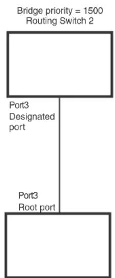
flowchart
graph TD
A["Bridge priority = 1500\nRouting Switch 2"] --> B["Port3\nDesignated port"]
B --> C["Port3\nRoot port"]
Routing Switch 3 Bridge priority = 2000
At power up, all ports on Switch 2 and Switch 3 assume Designated port roles and are at discarding states before they receive any RST BPDU.
Port3/Switch 2, with a Designated role, transmits an RST BPDU with a proposal flag to Port3/Switch 3. A port with a Designated role sends the proposal flag in its RST BPDU when they are ready to move to a forwarding state.
Port3/Switch 3, which starts with a role of Designated port, receives the RST BPDU and finds that it is superior to what it can transmit; therefore, Port3/Switch 3 assumes a new port role, that of a Root port. Port3/Switch 3 transmits an RST BPDU with an agreed flag back to Switch 2 and immediately goes into a forwarding state.
Port3/Switch 2 receives the RST BPDU from Port3/Switch 3 and immediately goes into a forwarding state.
Now RSTP has fully converged between the two bridges, with Port3/Switch 3 as an operational root port in forwarding state and Port3/Switch 2 as an operational Designated port in forwarding state.
Next, Switch 1 is powered up (Figure 54).
FIGURE 54 Simple Layer 2 topology

flowchart
graph TD
A["Switch 2"] -->|Port2, Root port| B["Switch 1"]
B -->|Port3, Designated port| A
B -->|Port4, Designated port| C["Switch 3"]
C -->|Port3, Alternate port| A
D["Switch 1"] -->|Port5, Backup port| B
E["Switch 2"] -->|Bridge priority = 1500| A
F["Switch 3"] -->|Bridge priority = 2000| A
G["Switch 1"] -->|Bridge priority = 1000| B
The point-to-point connections between the three bridges are as follows:
• Port2/Switch 1 and Port2/Switch 2
• Port4/Switch 1 and Port4/Switch 3
• Port3/Switch 2 and Port3/Switch 3
Ports 3 and 5 on Switch 1 are physically connected together.
At start up, the ports on Switch 1 assume Designated port roles, which are in discarding state. They begin sending RST BPDUs with proposal flags to move into a forwarding state.
When Port4/Switch 3 receives these RST BPDUs RSTP algorithm determines that they are better than the RST BPDUs that were previously received on Port3/Switch 3. Port4/Switch 3 is now selected as Root port. This new assignment signals Port3/Switch 3 to begin entering the discarding state and to assume an Alternate port role. As it goes through the transition, Port3/Switch 3 negotiates a new role and state with its peer port, Port3/Switch 2.
Port4/Switch 3 sends an RST BPDU with an agreed flag to Port4/Switch 1. Both ports go into forwarding states.
Port2/Switch 2 receives an RST BPDU. The RSTP algorithm determines that these RST BPDUs that are superior to any that any port on Switch 2 can transmit; therefore, Port2/Switch 2 assumes the role of a Root port.
The new Root port then signals all ports on the bridge to start synchronization. Since none of the ports are Edge ports, they all enter the discarding state and assume the role of Designated ports. Port3/Switch 2, which previously had a Designated role with a forwarding state, starts the discarding state. They also negotiate port roles and states with their peer ports. Port3/Switch 2 also sends an RST BPU to Port3/Switch 3 with a proposal flag to request permission go into a forwarding state.
The Port2/Switch 2 bridge also sends an RST BPDU with an agreed flag Port2/Switch 1 that Port2 is the new Root port. Both ports go into forwarding states.
Now, Port3/Switch 3 is currently in a discarding state and is negotiating a port role. It received RST BPDUs from Port3/Switch 2. The RSTP algorithm determines that the RST BPDUs Port3/Switch 3 received are superior to those it can transmit; however, they are not superior to those that are currently being received by the current Root port (Port4). Therefore, Port3 retains the role of Alternate port.
Ports 3/Switch 1 and Port5/Switch 1 are physically connected. Port5/Switch 1 received RST BPDUs that are superior to those received on Port3/Switch 1; therefore, Port5/Switch 1 is given the Backup port role while Port3 is given the Designated port role. Port3/Switch 1, does not go directly into a forwarding state. It waits until the forward delay time expires twice on that port before it can proceed to the forwarding state.
Once convergence is achieved, the active Layer 2 forwarding path converges as shown in Figure 55.
FIGURE 55 Active Layer 2 path
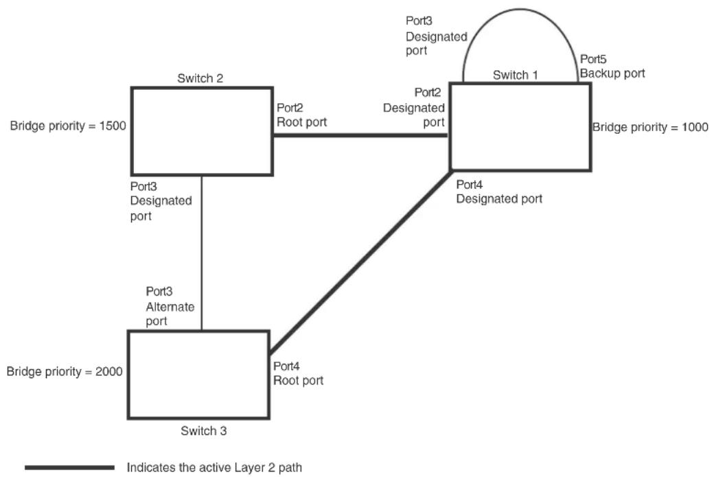
flowchart
graph TD
Switch1["Switch 1"] -->|Port3 Designated port| Switch2["Switch 2"]
Switch1 -->|Port5 Backup port| Switch3["Switch 3"]
Switch1 -->|Port4 Designated port| Switch4["Switch 4"]
Switch2 -->|Port2 Root port| Switch1
Switch2 -->|Port3 Designated port| Switch3
Switch3 -->|Port4 Root port| Switch4
Switch3 -->|Port3 Alternate port| Switch2
Switch1 -->|Bridge priority = 1000| Switch1
Switch2 -->|Bridge priority = 1500| Switch2
Switch3 -->|Bridge priority = 2000| Switch3
Switch1 -.->|Indicates the active Layer 2 path|
Convergence after a link failure
What happens if a link in the RSTP topology fails?
For example, Port2/Switch, which is the port that connects Switch 2 to the root bridge (Switch 1), fails. Both Switch 2 and Switch 1 notice the topology change (Figure 56).
FIGURE 56 Link failure in the topology

flowchart
graph TD
A["Switch 1"] -->|Port3| B["Switch 2"]
B -->|Port2| C["Switch 3"]
C -->|Port4| B
D["Switch 1"] -->|Port5| E["Switch 2"]
E -->|Port3| F["Switch 3"]
F -->|Port4| C
style A fill:#f9f,stroke:#333
style D fill:#f9f,stroke:#333
style B fill:#ccf,stroke:#333
style C fill:#ccf,stroke:#333
style E fill:#ccf,stroke:#333
Switch 1 sets its Port2 into a discarding state.
At the same time, Switch 2 assumes the role of a root bridge since its root port failed and it has no operational Alternate port. Port3/Switch 2, which currently has a Designated port role, sends an RST BPDU to Switch 3. The RST BPDU contains a proposal flag and a bridge ID of Switch 2 as its root bridge ID.
When Port3/Switch 3 receives the RST BPDUs, RSTP algorithm determines that they are inferior to those that the port can transmit. Therefore, Port3/Switch 3 is given a new role, that of a Designated port. Port3/Switch 3 then sends an RST BPDU with a proposal flag to Switch 2, along with the new role information. However, the root bridge ID transmitted in the RST BPDU is still Switch 1.
When Port3/Switch 2 receives the RST BPDU, RSTP algorithm determines that it is superior to the RST BPDU that it can transmit; therefore, Port3/Switch 2 receives a new role; that of a Root port. Port3/Switch 2 then sends an RST BPDU with an agreed flag to Port3/Switch 3. Port3/Switch 2 goes into a forwarding state.
When Port3/Switch 3 receives the RST BPDU that Port3/Switch 2 sent, Port3/Switch 3 changes into a forwarding state, which then completes the full convergence of the topology.
Convergence at link restoration
When Port2/Switch 2 is restored, both Switch 2 and Switch 1 recognize the change. Port2/Switch 1 starts assuming the role of a Designated port and sends an RST BPDU containing a proposal flag to Port2/Switch 2.
When Port2/Switch 2 receives the RST BPDUs, RSTP algorithm determines that the RST BPDUs the port received are better than those received on Port3/Switch 3; therefore, Port2/Switch 2 is given the role of a Root port. All the ports on Switch 2 are informed that a new Root port has been assigned which then signals all the ports to synchronize their roles and states. Port3/Switch 2, which was the previous Root port, enters a discarding state and negotiates with other ports on the bridge to establish its new role and state, until it finally assumes the role of a Designated port.
Next, the following happens:
- Port3/Switch 2, the Designated port, sends an RST BPDU, with a proposal flag to Port3/Switch 3.
- Port2/Switch 2 also sends an RST BPDU with an agreed flag to Port2/Switch 1 and then places itself into a forwarding state.
When Port2/Switch 1 receives the RST BPDU with an agreed flag sent by Port2/Switch 2, it puts that port into a forwarding state. The topology is now fully converged.
When Port3/Switch 3 receives the RST BPDU that Port3/Switch 2 sent, RSTP algorithm determines that these RST BPDUs are superior to those that Port3/Switch 3 can transmit. Therefore, Port3/Switch 3 is given a new role, that of an Alternate port. Port3/Switch 3 immediately enters a discarding state.
Now Port3/Switch 2 does not go into a forwarding state instantly like the Root port. It waits until the forward delay timer expires twice on that port while it is still in a Designated role, before it can proceed to the forwarding state. The wait, however, does not cause a denial of service, since the essential connectivity in the topology has already been established.
When fully restored, the topology is the same as that shown on Figure 54.
Convergence in a complex RSTP topology
The following is an example of a complex RSTP topology.
FIGURE 57 Complex RSTP topology

flowchart
graph TD
Switch1["Switch 1\nBridge priority = 1000"] -->|Port2| Switch2["Switch 2\nBridge priority = 200"]
Switch1 -->|Port3| Switch3["Switch 3\nBridge priority = 300"]
Switch2 -->|Port7| Switch4["Switch 4\nBridge priority = 400"]
Switch2 -->|Port8| Switch5["Switch 5\nBridge priority = 60"]
Switch3 -->|Port2| Switch3
Switch3 -->|Port3| Switch4
Switch4 -->|Port4| Switch3
Switch4 -->|Port5 Port5| Switch6["Switch 6\nBridge priority = 900"]
Switch5 -->|Port2| Switch2
Switch6 -->|Port3| Switch3
In Figure 57, Switch 5 is selected as the root bridge since it is the bridge with the highest priority. Lines in the figure show the point-to-point connection to the bridges in the topology.
Switch 5 sends an RST BPDU that contains a proposal flag to Port5/Switch 2. When handshakes are completed in Switch 5, Port5/Switch 2 is selected as the Root port on Switch 2. All other ports on Switch 2 are given Designated port role with discarding states.
Port5/Switch 2 then sends an RST BPDU with an agreed flag to Switch 5 to confirm that it is the new Root port and the port enters a forwarding state. Port7 and Port8 are informed of the identity of the new Root port. RSTP algorithm selects Port7 as the Designated port while Port8 becomes the Backup port.
Port3/Switch 5 sends an RST BPDU to Port3/Switch 6 with a proposal flag. When Port3/Switch 5 receives the RST BPDU, handshake mechanisms select Port3 as the Root port of Switch 6. All other ports are given a Designated port role with discarding states. Port3/Switch 6 then sends an RST BPDU with an agreed flag to Port3/Switch 5 to confirm that it is the Root port. The Root port then goes into a forwarding state.
Now, Port4/Switch 6 receives RST BPDUs that are superior to what it can transmit; therefore, it is given the Alternate port role. The port remains in discarding state.
Port5/Switch 6 receives RST BPDUs that are inferior to what it can transmit. The port is then given a Designated port role.
Next Switch 2 sends RST BPDUs with a proposal flag to Port3/Switch 4. Port3 becomes the Root port for the bridge; all other ports are given a Designated port role with discarding states.
Port3/Switch 4 sends an RST BPDU with an agreed flag to Switch 2 to confirm that it is the new Root port. The port then goes into a forwarding state.
Now Port4/Switch 4 receives an RST BPDU that is superior to what it can transmit. The port is then given an Alternate port role, and remains in discarding state.
Likewise, Port5/Switch 4 receives an RST BPDU that is superior to what it can transmit. The port is also given an Alternate port role, and remains in discarding state.
Port2/Switch 2 transmits an RST BPDU with a proposal flag to Port2/Switch 1. Port2/Switch 1 becomes the Root port. All other ports on Switch 1 are given Designated port roles with discarding states.
Port2/Switch 1 sends an RST BPDU with an agreed flag to Port2/Switch 2 and Port2/Switch 1 goes into a forwarding state.
Port3/Switch 1 receives an RST BPDUs that is inferior to what it can transmit; therefore, the port retains its Designated port role and goes into forwarding state only after the forward delay timer expires twice on that port while it is still in a Designated role.
Port3/Switch 2 sends an RST BPDU to Port3/Switch 3 that contains a proposal flag. Port3/Switch 3 becomes the Root port, while all other ports on Switch 3 are given Designated port roles and go into discarding states. Port3/Switch 3 sends an RST BPDU with an agreed flag to Port3/Switch 2 and Port3/Switch 3 goes into a forwarding state.
Now, Port2/Switch 3 receives an RST BPDUs that is superior to what it can transmit so that port is given an Alternate port state.
Port4/Switch 3 receives an RST BPDU that is inferior to what it can transmit; therefore, the port retains its Designated port role.
Ports on all the bridges in the topology with Designated port roles that received RST BPDUs with agreed flags go into forwarding states instantly. However, Designated ports that did not receive RST BPDUs with agreed flags must wait until the forward delay timer expires twice on those port. Only then will these port move into forwarding states.
The entire RSTP topology converges in less than 300 msec and the essential connectivity is established between the designated ports and their connected root ports.
After convergence is complete, Figure 58 shows the active Layer 2 path of the topology in Figure 57.
FIGURE 58 Active Layer 2 path in complex topology
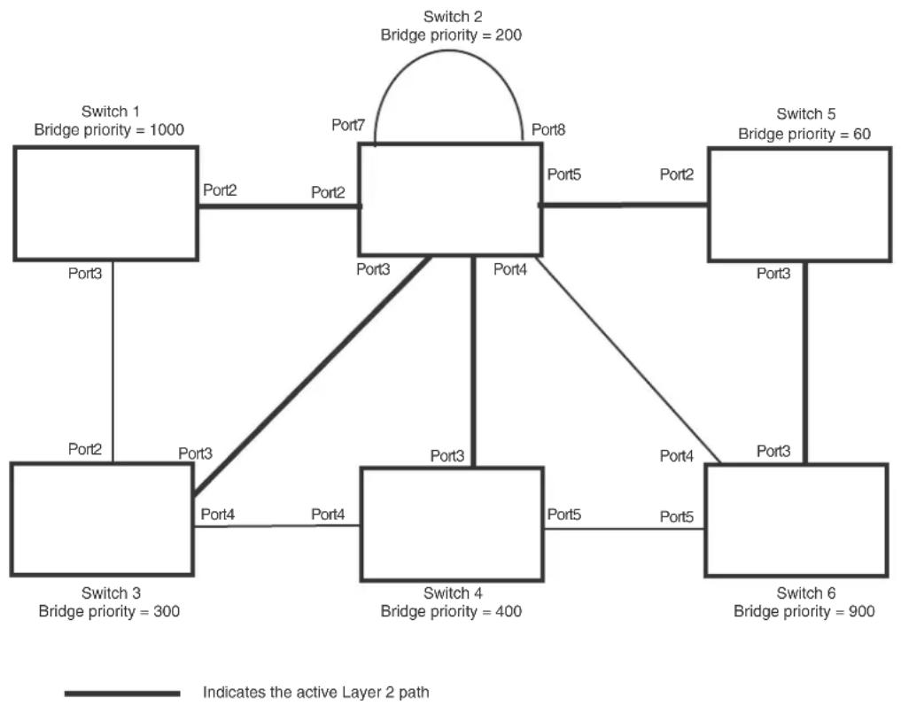
flowchart
graph TD
A["Switch 1\nBridge priority = 1000"] -->|Port2| B["Switch 2\nBridge priority = 200"]
B -->|Port7| C["Switch 3\nBridge priority = 300"]
B -->|Port8| D["Switch 5\nBridge priority = 60"]
C -->|Port4| E["Switch 4\nBridge priority = 400"]
D -->|Port5| F["Switch 6\nBridge priority = 900"]
E -->|Port3| C
E -->|Port4| B
F -->|Port3| C
F -->|Port5| D
style A fill:#f9f,stroke:#333
style B fill:#ccf,stroke:#333
style C fill:#cfc,stroke:#333
style D fill:#fcc,stroke:#333
style E fill:#cff,stroke:#333
style F fill:#ffc,stroke:#333
linkStyle 0 stroke:#000,stroke-width:2px
linkStyle 1 stroke:#000,stroke-width:2px
linkStyle 2 stroke:#000,stroke-width:2px
linkStyle 3 stroke:#000,stroke-width:2px
linkStyle 4 stroke:#000,stroke-width:2px
linkStyle 5 stroke:#000,stroke-width:2px
linkStyle 6 stroke:#000,stroke-width:2px
Propagation of topology change
The Topology Change state machine generates and propagates the topology change notification messages on each port. When a Root port or a Designated port goes into a forwarding state, the Topology Change state machine on those ports send a topology change notice (TCN) to all the bridges in the topology to propagate the topology change.
NOTE
Edge ports, Alternate ports, or Backup ports do not need to propagate a topology change.
The TCN is sent in the RST BPDU that a port sends. Ports on other bridges in the topology then acknowledge the topology change once they receive the RST BPDU, and send the TCN to other bridges until all the bridges are informed of the topology change.
For example, Port3/Switch 2 in Figure 59, fails. Port4/Switch 3 becomes the new Root port. Port4/Switch 3 sends an RST BPDU with a TCN to Port4/Switch 4. To propagate the topology change, Port4/Switch 4 then starts a TCN timer on itself, on the bridge's Root port, and on other ports on that bridge with a Designated role. Then Port3/Switch 4 sends RST BPDU with the TCN to Port4/Switch 2. (Note the new active Layer 2 path in Figure 59.)
FIGURE 59 Beginning of topology change notice

flowchart
graph TD
A["Switch 1\nBridge priority = 1000"] -->|Port2 Port2| B["Switch 2\nBridge priority = 200"]
B -->|Port3| C["Switch 3\nBridge priority = 300"]
B -->|Port4| D["Switch 4\nBridge priority = 400"]
B -->|Port5| E["Switch 5\nBridge priority = 60"]
C -->|Port3| F["Switch 6\nBridge priority = 900"]
D -->|Port4| F
E -->|Port5| F
F -->|Port3| B
B -->|Port7 Port8| B
B -->|Port4| D
D -->|Port3| C
D -->|Port5| E

Indicates the active Layer 2 path

Indicates direction of TCN
Switch 2 then starts the TCN timer on the Designated ports and sends RST BPDUs that contain the TCN as follows (Figure):
- Port5/Switch 2 sends the TCN to Port2/Switch 5
- Port4/Switch 2 sends the TCN to Port4/Switch 6
- Port2/Switch 2 sends the TCN to Port2/Switch 1
FIGURE 60 Sending TCN to bridges connected to Switch 2

flowchart
graph TD
A["Switch 1 Bridge priority = 1000"] -->|Port2| B["Switch 2 Bridge priority = 200"]
B -->|Port5| C["Switch 5 Bridge priority = 60"]
C -->|Port3| D["Switch 6 Bridge priority = 900"]
D -->|Port4| E["Switch 4 Bridge priority = 400"]
E -->|Port5| F["Switch 3 Bridge priority = 300"]
F -->|Port4 Port4| G["Switch 3 Bridge priority = 300"]
G -->|Port3| H["Switch 1 Bridge priority = 1000"]
H -->|Port2| I["Switch 2 Bridge priority = 200"]
I -->|Port7 Port8| B
B -->|Port2| J["Switch 4 Bridge priority = 400"]
J -->|Port5| K["Switch 6 Bridge priority = 900"]
K -->|Port3| L["Switch 5 Bridge priority = 60"]
L -->|Port2| M["Switch 2 Bridge priority = 200"]
M -->|Port7 Port8| N["Switch 1 Bridge priority = 1000"]
N -->|Port2| O["Switch 3 Bridge priority = 300"]
O -->|Port4 Port4| P["Switch 4 Bridge priority = 400"]
P -->|Port5| Q["Switch 6 Bridge priority = 900"]
Q -->|Port3| R["Switch 5 Bridge priority = 60"]
R -->|Port2| S["Switch 2 Bridge priority = 200"]
S -->|Port7 Port8| T["Switch 1 Bridge priority = 1000"]
T -->|Port2| U["Switch 3 Bridge priority = 300"]
U -->|Port4 Port4| V["Switch 4 Bridge priority = 400"]
V -->|Port5 Port5| W["Switch 6 Bridge priority = 900"]
W -->|Port3| X["Switch 5 Bridge priority = 60"]
X -->|Port2| Y["Switch 2 Bridge priority = 200"]
Y -->|Port7 Port8| Z["Switch 1 Bridge priority = 1000"]
Z -->|Port2| AA["Switch 3 Bridge priority = 300"]
AA -->|Port4 Port4| AB["Switch 4 Bridge priority = 400"]
AB -->|Port5 Port5| AC["Switch 6 Bridge priority = 900"]
AC -->|Port3| AD["Switch 5 Bridge priority = 60"]
AD -->|Port2| AE["Switch 2 Bridge priority = 200"]
AE -->|Port7 Port8| AF["Switch 1 Bridge priority = 1000"]
AF -->|Port2 Port4| AG["Switch 3 Bridge priority = 300"]
AG -->|Port4 Port4| AH["Switch 4 Bridge priority = 400"]
AH -->|Port5 Port5| AI["Switch 6 Bridge priority = 900"]
AI -->|Port3 Port3| AJ["Switch 5 Bridge priority = 60"]
AJ -->|Port2 Port2| AK["Switch 2 Bridge priority = 200"]
AK -->|Port7 Port8| AL["Switch 1 Bridge priority = 1000"]
AL -->|Port2 Port2| AM["Switch 3 Bridge priority = 300"]
AM -->|Port4 Port4| AN["Switch 4 Bridge priority = 400"]
AN -->|Port5 Port5| AO["Switch 6 Bridge priority = 900"]
AO -->|Port3 Port3| AP["Switch 5 Bridge priority = 60"]
AP -->|Port2 Port2| AQ["Switch 2 Bridge priority = 200"]
AQ -->|Port7 Port8| AR["Switch 1 Bridge priority = 1000"]
AR -->|Port2 Port2| AS["Switch 3 Bridge priority = 300"]
AS -->|Port4 Port4| AT["Switch 4 Bridge priority = 400"]
AT -->|Port5 Port5| AU["Switch 6 Bridge priority = 900"]
AU -->|Port3 Port3| AV["Switch 5 Bridge priority = 60"]
AV -->|Port2 Port2| AW["Switch 2 Bridge priority = 200"]
AW -->|Port7 Port8| AX["Switch 1 Bridge priority = 1000"]
AX -->|Port2 Port2| AY["Switch 3 Bridge priority = 300"]
YA["Indicates the active Layer 2 path"] --> AZ["Indicates direction of TCN"]
Then FRY1, Switch 5, and Switch 6 send RST BPDUs that contain the TCN to Switch 3 and Switch 4 to complete the TCN propagation (Figure 61).
FIGURE 61 Completing the TCN propagation
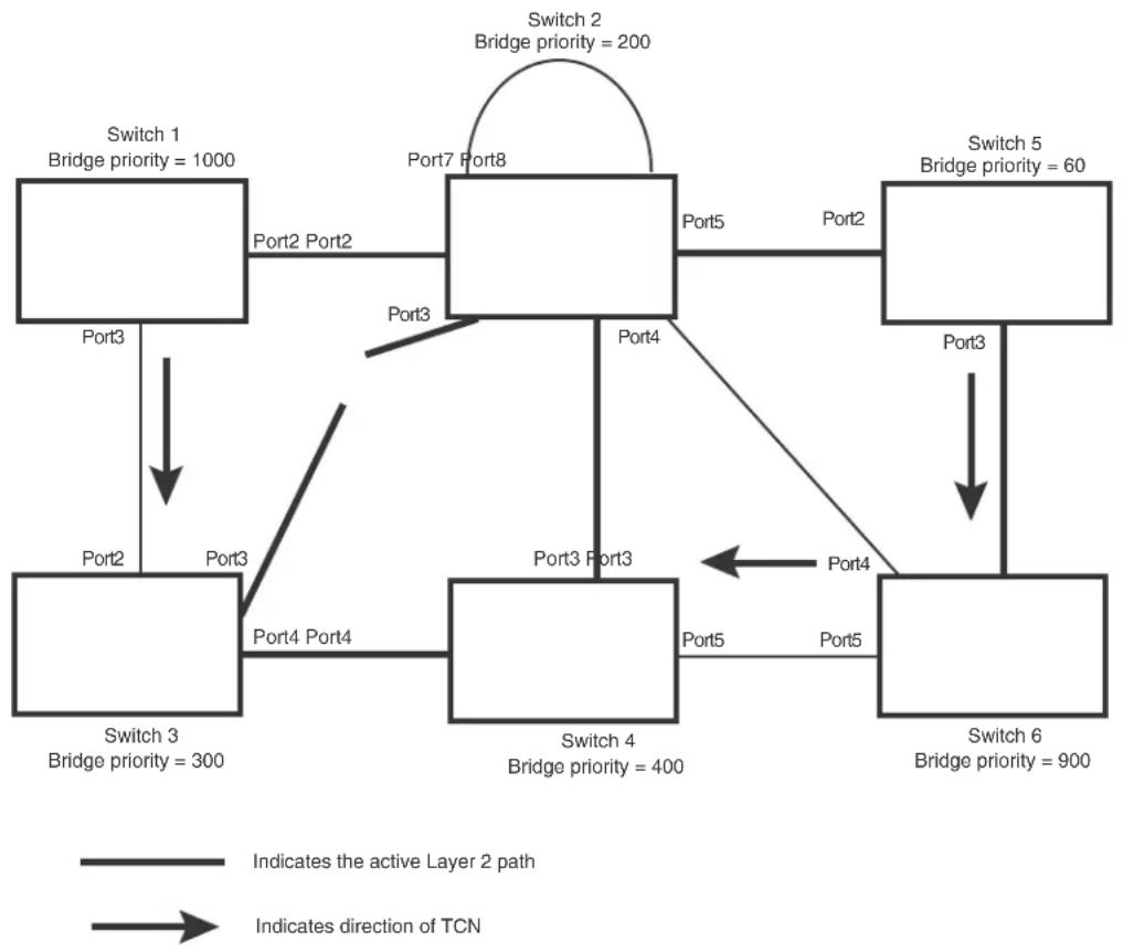
flowchart
graph TD
A["Switch 1 Bridge priority = 1000"] -->|Port2 Port2| B["Switch 2 Bridge priority = 200"]
B -->|Port3 Port3| C["Switch 3 Bridge priority = 300"]
B -->|Port4 Port4| D["Switch 4 Bridge priority = 400"]
B -->|Port5 Port5| E["Switch 5 Bridge priority = 60"]
E -->|Port3 Port3| F["Switch 6 Bridge priority = 900"]
D -->|Port4 Port4| B
D -->|Port5 Port5| E
style A fill:#f9f,stroke:#333
style B fill:#ccf,stroke:#333
style C fill:#cfc,stroke:#333
style D fill:#fcc,stroke:#333
style E fill:#ffc,stroke:#333
linkStyle 0 stroke:#000,stroke-width:2px
linkStyle 1 stroke:#000,stroke-width:2px
linkStyle 2 stroke:#000,stroke-width:2px
linkStyle 3 stroke:#000,stroke-width:2px
linkStyle 4 stroke:#000,stroke-width:2px
linkStyle 5 stroke:#000,stroke-width:2px
linkStyle 6 stroke:#000,stroke-width:2px
note right of B
Indicates the active Layer 2 path
Indicates direction of TCN
end
Compatibility of RSTP with 802.1D
RSTP-enabled bridges are backward compatible with IEEE 802.1D bridges. This compatibility is managed on a per-port basis by the Port Migration state machine. However, intermixing the two types of bridges in the network topology is not advisable if you want to take advantage of the rapid convergence feature.
Compatibility with 802.1D means that an RSTP-enabled port can send BPDUs in the STP or 802.1D format when one of the following events occur:
- The port receives a legacy BPDU. A legacy BPDU is an STP BPDU or a BPDU in an 802.1D format. The port that receives the legacy BPDU automatically configures itself to behave like a legacy port. It sends and receives legacy BPDUs only.
- The entire bridge is configured to operate in an 802.1D mode when an administrator sets the
• bridge parameter to zero at the CLI, forcing all ports on the bridge to send legacy BPDUs only.
Once a port operates in the 802.1D mode, 802.1D convergence times are used and rapid convergence is not realized.
For example, in Figure 62, Switch 10 and Switch 30 receive legacy BPDUs from Switch 20. Ports on Switch 10 and Switch 30 begin sending BPDUs in STP format to allow them to operate transparently with Switch 20.
FIGURE 62 RSTP bridges with an 802.1D bridge

Once Switch 20 is removed from the LAN, Switch 10 and Switch 30 receive and transmit BPDUs in the STP format to and from each other. This state will continue until the administrator enables the force-migration-check command to force the bridge to send RSTP BPDU during a migrate time period. If ports on the bridges continue to hear only STP BPDUs after this migrate time period, those ports will return to sending STP BPDUs. However, when the ports receive RST BPDUs during the migrate time period, the ports begin sending RST BPDUs. The migrate time period is non-configurable. It has a value of three seconds.
NOTE
The IEEE standards state that RSTP bridges need to interoperate with 802.1D bridges. IEEE standards set the path cost of RSTP bridges to be between 1 and 200,000,000; whereas path cost of 802.1D bridges are set between 1 and 65,535. In order for the two bridge types to be able to interoperate in the same topology, the administrator needs to configure the bridge path cost appropriately. Path costs for either RSTP bridges or 802.1D bridges need to be changed; in most cases, path costs for RSTP bridges need to be changed.
Configuring RSTP parameters
The remaining RSTP sections explain how to configure the RSTP protocol on a device.
You can enable or disable RSTP at the following levels:
- Port-based VLAN – Affects all ports within the specified port-based VLAN. When you enable or disable RSTP within a port-based VLAN, the setting overrides the global setting. Thus, you can enable RSTP for the ports within a port-based VLAN even when RSTP is globally disabled, or disable the ports within a port-based VLAN when RSTP is globally enabled.
- Individual port – Affects only the individual port. However, if you change the RSTP state of the primary port in a trunk group, the change affects all ports in the trunk group.
Enabling or disabling RSTP in a port-based VLAN
Use the following procedure to disable or enable RSTP on a device on which you have configured a port-based VLAN. Changing the RSTP state in a VLAN affects only that VLAN.
To enable RSTP for all ports in a port-based VLAN, enter commands such as the following.
BigIron RX(config)# vlan 10
BigIron RX(config-vlan-10)# rstp
Syntax: [no] rstp
Enabling or disabling RSTP on a single spanning tree
To globally enable RSTP for all ports of a single spanning tree, enter the following command.
BigIron RX(config)# rstp single
Syntax: [no] rstp single
Disabling or enabling RSTP on a port
The rstp command must be used to initially enable RSTP on ports. Both commands enable RSTP on all ports that belong to the VLAN or to the single spanning tree.
Once RSTP is enabled on a port, it can be disabled on individual ports. RSTP that have been disabled on individual ports can then be enabled as required.
NOTE
If you change the RSTP state of the primary port in a trunk group, the change affects all ports in that trunk group.
To disable or enable RSTP on a port, enter commands such as the following.
BigIron RX(config)# interface 1/1
BigIron RX(config-if-e1000-1/1)# no spanning-tree
Syntax: [no] spanning-tree [protect]
The value of protect will drop the BPDUs received on that specific interface.
Changing RSTP bridge parameters
When you make changes to RSTP bridge parameters, the changes are applied to individual ports on the bridge.
To designate a priority for a bridge, enter a command such as the following at the VLAN level.
BigIron RX(config)# vlan 20
BigIron RX(config-vlan-20)# rstp priority 0
To make this change in the default VLAN, enter the following commands.
BigIron RX(config)# vlan 1
BigIron RX(config-vlan-1)# rstp priority 0
Syntax: spanning-tree 802-1w [forward-delay
The forward-delay
The hello-time
The max-age
The value of max-age must be greater than the value of forward-delay to ensure that the downstream bridges do not age out faster than the upstream bridges (those bridges that are closer to the root bridge).
The force-version
- 0 – The STP compatibility mode. Only STP (or legacy) BPDUs will be sent.
- 2 – The default. RST BPDUs will be sent unless a legacy bridge is detected. If a legacy bridge is detected, STP BPDUs will be sent instead.
The priority
You can specify some or all of these parameters on the same command line.
Changing port parameters
The RSTP port commands can be enabled on individual ports or on multiple ports, such as all ports that belong to a VLAN.
The RSTP port parameters are preconfigured with default values. If the default parameters meet your network requirements, no other action is required.
You can change the following RSTP port parameters using the following methods.
BigIron RX(config)# vlan 10
BigIron RX(config-vlan-10)# rstp ethernet 1/5 path-cost 15 priority 64
At the VLAN configuration level of the CLI.
Syntax: rstp ethernet <slot>/<portnum> path-cost <value> | priority <value> | [admin-edge-port] | [admin-pt2pt-mac] | [force-migration-check]
At the interface level of the CLI.
Syntax: rstp [admin-edge-port] | [admin-pt2pt-mac]
The ethernet
The path-cost
TABLE 79 Recommended path cost values of RSTP
| Link speed Recommended (default) RSTP path cost values | Recommended RSTP path cost range | |
| Less than 100 kilobits per second 200,000,000 20,000,000 - 200,000,000 | ||
| 1 Megabit per second 20,000,000 2,000,000 - 200,000,000 | ||
| 10 Megabits per second 2,000,000 200,000 - 200,000,000 | ||
| 100 Megabits per second | 200,000 | 20,000 - 200,000,000 |
| Link speed | Recommended (default) RSTP path cost values | Recommended RSTP path cost range |
| 1 Gigabit per second 20,000 2,000 - 200,000,000 | ||
| 10 Gigabits per second 2,000 200 - 20,000 | ||
| 100 Gigabits per second 200 20 - 2,000 | ||
| 1 Terabits per second 20 2 - 200 | ||
| 10 Terabits per second 2 1 - 20 | ||
The priority
Set the admin-edge-port to enabled or disabled. If set to enabled, then the port becomes an edge port in the domain.
Set the admin-pt2pt-mac to enabled or disabled. If set to enabled, then a port is connected to another port through a point-to-point link. The point-to-point link increases the speed of convergence. This parameter, however, does not auto-detect whether or not the link is a physical point-to-point link.
The force-migration-check parameter forces the specified port to sent one RST BPDU. If only STP BPDUs are received in response to the sent RST BPDU, then the port will go return to sending STP BPDUs.
Suppose you want to enable RSTP on a system with no active port-based VLANs and change the hello-time from the default value of 2 to 8 seconds. Additionally, suppose you want to change the path and priority costs for port 5 only. To do so, enter the following commands.
BigIron RX(config)# spanning-tree 802-lw hello-time 8 BigIron RX(config)# spanning-tree 802-lw ethernet 5 path-cost 15 priority 64
Fast port span
When STP is running on a device, message forwarding is delayed during the spanning tree recalculation period following a topology change. The STP forward delay parameter specifies the period of time a bridge waits before forwarding data packets. The forward delay controls the listening and learning periods of STP reconvergence. You can configure the forward delay to a value from 4 – 30 seconds. The default is 15 seconds. Thus, using the standard forward delay, convergence requires 30 seconds (15 seconds for listening and an additional 15 seconds for learning) when the default value is used.
This slow convergence is undesirable and unnecessary in some circumstances. The Fast Port Span feature allows certain ports to enter the forwarding state in four seconds. Specifically, Fast Port Span allows faster convergence on ports that are attached to end stations and thus do not present the potential to cause Layer 2 forwarding loops. Because the end stations cannot cause forwarding loops, they can safely go through the STP state changes (blocking to listening to learning to forwarding) more quickly than is allowed by the standard STP convergence time. Fast Port Span performs the convergence on these ports in four seconds (two seconds for listening and two seconds for learning).
In addition, Fast Port Span enhances overall network performance in the following ways:
- Fast Port Span reduces the number of STP topology change notifications on the network. When an end station attached to a Fast Span port comes up or down, the Brocade device does not generate a topology change notification for the port. In this situation, the notification is unnecessary since a change in the state of the host does not affect the network's topology.
- Fast Port Span eliminates unnecessary MAC cache aging that can be caused by topology change notifications. Bridging devices age out the learned MAC addresses in their MAC caches if the addresses are unrefreshed for a given period of time, sometimes called the MAC aging interval. When STP sends a topology change notification, devices that receive the notification use the value of the STP forward delay to quickly age out their MAC caches. For example, if a device's normal MAC aging interval is 5 minutes, the aging interval changes temporarily to the value of the forward delay (for example, 15 seconds) in response to an STP topology change.
In normal STP, the accelerated cache aging occurs even when a single host goes up or down. Because Fast Port Span does not send a topology change notification when a host on a Fast Port Span port goes up or down, the unnecessary cache aging that can occur in these circumstances under normal STP is eliminated.
Fast Port Span is a system-wide parameter and is enabled by default. Thus, when you boot a device, all the ports that are attached only to end stations run Fast Port Span. For ports that are not eligible for Fast Port Span, such as ports connected to other networking devices, the device automatically uses the normal STP settings. If a port matches any of the following criteria, the port is ineligible for Fast Port Span and uses normal STP instead:
• The port is 802.1q tagged
• The port is a member of a trunk group
- The port has learned more than one active MAC address
- An STP Configuration BPDU has been received on the port, thus indicating the presence of another bridge on the port.
You also can explicitly exclude individual ports from Fast Port Span if needed. For example, if the only uplink ports for a wiring closet switch are Gigabit ports, you can exclude the ports from Fast Port Span.
Disabling and re-enabling fast port span
Fast Port Span is a system-wide parameter and is enabled by default. Thus all ports that are eligible for Fast Port Span use it.
To disable or re-enable Fast Port Span, use the following method.
Using the CLI
To disable Fast Port Span, enter the following commands.
BigIron RX(config)# no fast port-span BigIron RX(config)# write memory
Syntax: [no] fast port-span
NOTE
The fast port-span command has additional parameters that let you exclude specific ports. These parameters are shown in the following section.
To re-enable Fast Port Span, enter the following commands.
BigIron RX(config)# fast port-span
BigIron RX(config)# write memory
Excluding specific ports from fast port span
You can exclude individual ports from Fast Port Span while leaving Fast Port Span enabled globally. To do so, use the following method.
Using the CLI
To exclude a port from Fast Port Span, enter commands such as the following.
BigIron RX(config)# fast port-span exclude ethernet 1/1
BigIron RX(config)# write memory
To exclude a set of ports from Fast Port Span, enter commands such as the following.
BigIron RX(config)# fast port-span exclude ethernet 1/1 ethernet 2/1 ethernet 3/2 BigIron RX(config)# write memory
To exclude a contiguous (unbroken) range of ports from Fast Span, enter commands such as the following.
BigIron RX(config)# fast port-span exclude ethernet 1/1 to 1/24
BigIron RX(config)# write memory
Syntax: [no] fast port-span [exclude ethernet
To re-enable Fast Port Span on a port, enter a command such as the following.
BigIron RX(config)# no fast port-span exclude ethernet 1/1
BigIron RX(config)# write memory
This command re-enables Fast Port Span on port 1/1 only and does not re-enable Fast Port Span on other excluded ports. You also can re-enable Fast Port Span on a list or range of ports using the syntax shown above this example.
To re-enable Fast Port Span on all excluded ports, disable and then re-enable Fast Port Span by entering the following commands.
BigIron RX(config)# no fast port-span
BigIron RX(config)# fast port-span
BigIron RX(config)# write memory
Disabling and then re-enabling Fast Port Span clears the exclude settings and thus enables Fast Port Span on all eligible ports. To make sure Fast Port Span remains enabled on the ports following a system reset, save the configuration changes to the startup-config file after you re-enable Fast Port Span. Otherwise, when the system resets, those ports will again be excluded from Fast Port Span.
Fast uplink span
The Fast Port Span feature described in the previous section enhances STP performance for end stations. The Fast Uplink feature enhances STP performance for wiring closet switches with redundant uplinks. Using the default value for the standard STP forward delay, convergence following a transition from an active link to a redundant link can take 30 seconds (15 seconds for listening and an additional 15 seconds for learning).
You can use the Fast Uplink feature on a Brocade device deployed as a wiring closet switch to decrease the convergence time for the uplink ports to another device to just four seconds (two seconds for listening and two seconds for learning). The wiring closet switch must be a Brocade device but the device at the other end of the link can be a Brocade device or another vendor's switch. Configuration of the Fast Uplink Span feature takes place entirely on the Brocade device.
To configure the Fast Uplink Span feature, specify a group of ports that have redundant uplinks on the wiring closet switch (Brocade device) as members of a Fast Uplink Group. If the active link becomes unavailable, the Fast Uplink Span feature transitions the forwarding to one of the other ports in four seconds. You can configure one Fast Uplink Span group on the device. All Fast Uplink Span ports are members of the same Fast Uplink Span group.
NOTE
To avoid the potential for temporary bridging loops, Brocade recommends that you use the Fast Uplink feature only for wiring closet switches (switches at the edge of the network cloud). In addition, enable the feature only on a group of ports intended for redundancy, so that at any given time only one of the ports is expected to be in the forwarding state.
NOTE
When the device first comes up or when STP is first enabled, the uplink ports still must go through the standard STP state transition without any acceleration. This behavior guards against temporary routing loops as the switch tries to determine the states for all the ports. Fast Uplink Span acceleration applies only when a working uplink becomes unavailable.
Fast uplink span rules for trunk groups
If you add a port to a Fast Uplink Span group that is a member of a trunk group, the following rules apply:
- If you add the primary port of a trunk group to the Fast Uplink Span group, all other ports in the trunk group are automatically included in the group. Similarly, if you remove the primary port in a trunk group from the Fast Uplink Span group, the other ports in the trunk group are automatically removed from the Fast Uplink Span group.
- You cannot add a subset of the ports in a trunk group to the Fast Uplink Span group. All ports in a trunk group have the same Fast Uplink Span property, as they do for other port properties.
- If the working trunk group is partially down but not completely down, no switch-over to the backup occurs. This behavior is the same as in the standard STP feature.
- If the working trunk group is completely down, a backup trunk group can go through an accelerated transition only if the following are true:
- The trunk group is included in the fast uplink group.
- All other ports except those in this trunk group are either disabled or blocked. The accelerated transition applies to all ports in this trunk group.
- When the original working trunk group comes back (partially or fully), the transition back to the original topology is accelerated if the conditions listed above are met.
Configuring a fast uplink port group
To enable Fast Uplink, use the following method.
Using the CLI
To configure a group of ports for Fast Uplink Span, enter the following commands.
BigIron RX(config)# fast uplink-span ethernet 4/1 to 4/4 BigIron RX(config)# write memory
Syntax: [no] fast uplink-span [ethernet
This example configures four ports, 4/1 - 4/4, as a Fast Uplink Span group. In this example, all four ports are connected to a wiring closet switch. Only one of the links is expected to be active at any time. The other links are redundant. For example, if the link on port 4/1 is the active link on the wiring closet switch but becomes unavailable, one of the other links takes over. Because the ports are configured in a Fast Uplink Span group, the STP convergence takes about four seconds instead of taking 30 seconds or longer using the standard STP forward delay.
If you add a port that is the primary port of a trunk group, all ports in the trunk group become members of the Fast Uplink Span group.
You can add ports to a Fast Uplink Span group by entering the fast uplink-span command additional times with additional ports. The device can have only one Fast Uplink Span group, so all the ports you identify as Fast Uplink Span ports are members of the same group.
To remove a Fast Uplink Span group or to remove individual ports from a group, use "no" in front of the appropriate fast uplink-span command. For example, to remove ports 4/3 and 4/4 from the Fast Uplink Span group configured above, enter the following commands.
BigIron RX(config)# no fast uplink-span ethernet 4/3 to 4/4 BigIron RX(config)# write memory
If you delete a port that is the primary port of a trunk group, all ports in the trunk group are removed from the Fast Uplink Span group.
Displaying RSTP information
You can display a summary or details of the RSTP information.
To display a summary of RSTP, enter the following command.
BigIron RX(config)#show rstp vlan 10
VLAN 10 - RSTP instance 0
RSTP (IEEE 802.1w) Bridge Parameters:
| Bridge | Bridge | Bridge | Bridge | Force | tx |
| Identifier | MaxAge | Hello | FwdDly | Version | Hold |
| hex | sec | sec | sec | cnt | |
| 0001000480a04000 | 20 | 2 | 15 | Default | 3 |
| RootBridge Identifier hex | RootPath Cost | DesignatedBridge Identifier hex | Root Port | Max Age sec | Hel lo sec | Fwd Dly sec |
| 0001000480a04000 | 0 | 0001000480a04000 | Root | 20 | 2 | 15 |
RSTP (IEEE 802.1w) Port Parameters:
| <---- Config Params --> | <---- Current state --> | |||||||
| Port Num | Pri | PortPath Cost | P2P Mac | Edge Port | Role | State | Designated cost | Designated bridge |
| 1/3 | 128 | 20000 | T | F | DISABLED | DISABLED | 0 | 0000000000000000 |
| 1/13 | 128 | 20000 | T | F | DISABLED | DISABLED | 0 | 0000000000000000 |
Syntax: show rstp [vlan
The vlan
The show RSTP display command shows the information listed in Table 80.
TABLE 80 CLI display of RSTP summary
| This field... Displays... | |
| VLAN ID The port-based VLAN that owns the STP instance and the number of RSTPinstances on that VLAN. VLAN 1 is the default VLAN. If you have not configured port-based VLANs on this device, all RSTP information is for VLAN 1. | |
| Bridge IEEE RSTP parameters | |
| Bridge Identifier The ID of the bridge. | |
| Bridge Max Age The configured max age for this bridge. The default is 20. | |
| Bridge Hello The configured hello time for this bridge.The default is 2. | |
| Bridge FwdDly The configured forward delay time for this bridge. The default is 15. | |
| Force-Version The configured force version value. One of the following values is displayed:0 – The bridge has been forced to operate in an STP compatibility mode.2 – The bridge has been forced to operate in an RSTP mode. (This is the default.) | |
| txHoldCnt The number of BPDUs that can be transmitted per Hello Interval. The default is 3. | |
| Root bridge parameters: | |
| Root Bridge Identifier | ID of the Root bridge that is associated with this bridge |
| Root Path Cost | The cost to reach the root bridge from this bridge. If the bridge is the root bridge, then this parameter shows a value of zero. |
| This field... | Displays... |
| Designated Bridge Identifier The bridge from where the root information was received. It can be from the root bridge itself, but it could also be from another bridge. | |
| Root Port The port on which the root information was received. This is the port that is connected to the Designated Bridge. | |
| Max Age | The max age is derived from the Root port. An RSTP-enabled bridge uses this value, along with the hello and message age parameters to compute the effective age of an RST BPDU.Themessage ageparameter is generated by the Designated port and transmitted in the RST BPDU. RST BPDUs transmitted by a Designated port of the root bridge contains a message value of zero.Effective ageis the amount of time the Root port, Alternate port, or Backup port retains the information it received from its peer Designated port.Effective age is reset every time a port receives an RST BPDU from its Designated port. If a Root port does not receive an RST BPDU from its peer Designated port for a duration more than the effective age, the Root port ages out the existing information and recomputes the topology.If the port is operating in 802.1D compatible mode, then max age functionality is the same as in 802.1D (STP). |
| Hello The hello value derived from the Root port. It is the number of seconds between two Hello packets. | |
| Fwd Dly The number of seconds a non-edge Designated port waits until it can applyany of the following transitions, if the RST BPDU it receives does not have an agreed flag:Discarding state to learning stateLearning state to forwarding stateWhen a non-edge port receives the RST BPDU it goes into forwarding state within 4 seconds or after two hello timers expire on the port.Fwd Dly is also the number of seconds that a Root port waits for an RST BPDU with a proposal flag before it applies the state transitions listed above.If the port is operating in 802.1D compatible mode, then forward delay functionality is the same as in 802.1D (STP). | |
RSTP (IEEE 802.1W) port parameters
| Port Num The port number shown in a slot#/port# format. |
| Pri The configured priority of the port. The default is 128 or 0x80. |
| Port Path Cost The configured path cost on a link connected to this port. |
| P2P Mac Indicates if the point-to-point-mac parameter is configured to be a point-to-point link:• T – The link is configured as a point-to-point link.• F – The link is not configured as a point-to-point link. This is the default. |
Edge port Indicates if the port is configured as an operational Edge port:
- T – The port is configured as an Edge port.
- F - The port is not configured as an Edge port. This is the default.
TABLE 80 CLI display of RSTP summary (Continued)
| This field... | Displays... |
| Role The current role of the port:RootDesignatedAlternateBackupDisabledRefer to “Bridges and bridge port roles” on page 357 for definitions of the roles. | |
| State The port’s current RSTP state. A port can have one of the following states:ForwardingDiscardingLearningDisabledRefer to “Bridge port states” on page 361 and “Edge port and non-edge port states” on page 362. | |
| Designated Cost The best root path cost that this port received, including the best root path cost that it can transmit. | |
| Designated Bridge The ID of the bridge that sent the best RST BPDU that was received on this port. | |
To display detailed information about RSTP, enter the following command.
BigIron RX(config)#show rstp detail VLAN 10 - RSTP instance 0
RSTP (IEEE 802.1w) Bridge Parameters:
BridgeId 0001000480a04000, RootBridgeId 0001000480a04000 Control ports - ethe 1/3 ethe 1/13 ForceVersion 2, MigrateTime 3, TxHoldCount 3
RSTP (IEEE 802.1w) Port Parameters:
Port 1/3 - Role: DISABLED - State: DISABLED Port 1/13 - Role: DISABLED - State: DISABLED
Syntax: show rstp detail [vlan
The vlan
TABLE 81 The show rstp detail command output
| This field... Displays... |
| VLAN ID ID of the VLAN that owns the instance of RSTP and the number of RSTP instances on that VLAN. |
| Bridge ID ID of the bridge. |
Control ports Ports assigned to the VLAN
TABLE 81 The show rstp detail command output (Continued)
| This field... | Displays... |
| forceVersion the configured version of the bridge:0 - The bridge has been forced to operate in an STP compatible mode.2 - The bridge has been forced to operate in an RSTP mode. | |
| MigrateTime The number of seconds the bridge took to migrate from STP to RSTP mode. | |
| txHoldCount The number of BPDUs that can be transmitted per Hello Interval. The default is 3. | |
| Port ID of the port in slot#/port# format. | |
| Role The current role of the port:RootDesignatedAlternateBackupDisabledRefer to “Bridges and bridge port roles” on page 357 for definitions of the roles. | |
| State The port’s current RSTP state. A port can have one of the following states:ForwardingDiscardingLearningDisabledRefer to “Bridge port states” on page 361 and “Edge port and non-edge port states” on page 362. | |
| Path Cost The configured path cost on a link connected to this port. | |
| Priority The configured priority of the port. The default is 128 or 0x80. | |
| AdminOperEdge Indicates if the port is an operational Edge port. Edge ports may either be auto-detected or configured (forced) to be Edge ports:T - The port is and Edge port.F - The port is not an Edge port. This is the default. | |
| AdminP2PMac Indicates if the point-to-point-mac parameter is configured to be a point-to-point link:T - The link is a point-to-point linkF - The link is not a point-to-point link. This is the default. | |
| DesignatedPriority Shows the following:Root - Shows the ID of the root bridge for this bridge.Bridge - Shows the ID of the Designated bridge that is associated with this port. | |
| This field... Displays... | |
| ActiveTimers Shows what timers are currently active on this port and the number of seconds they have before they expire:rrWhile - Recent root timer. A non-zero value means that the port has recently been a Root port.rcvdInfoWhile - Received information timer. Shows the time remaining before the information held by this port expires (ages out). This timer is initialized with the effective age parameter. (See “Max Age” on page 394.)rbWhile - Recent backup timer. A non-zero value means that the port has recently been a Backup port.helloWhen - Hello period timer. The value shown is the amount of time between hello messages.tcWhile - Topology change timer. The value shown is the interval when topology change notices can be propagated on this port.fdWhile - Forward delay timer. (See the explanation for Fwd Dly on page 394.)mdelayWhile - Migration delay timer. The amount of time that a bridge on the same LAN has to synchronize its migration state with this port before another BPDU type can cause this port to change the BPDU that it transmits. | |
| Machine States The current states of the various state machines on the port:PIM - State of the Port Information state machine.PRT - State of the Port Role Transition state machine.PST - State of the Port State Transition state machine.TCM - State of the Topology Change state machine.PPM - State of the Port Protocol Migration.PTX - State of the Port Transmit state machine.Refer to the section “State machines” on page 362 for details on state machines. | |
| Received Shows the number of BPDU types the port has received:RST BPDU - BPDU in RSTP format.Config BPDU - Legacy configuration BPDU (802.1D format).TCN BPDU - Legacy topology change BPDU (802.1D format). | |
Displaying RSTP information for the specified Ethernet interface
To display the RSTP information for the specified Ethernet interface, enter the following command at any level of the CLI.
BigIron RX# show xstp Ethernet 3/1
STP information:
No STP-configured VLANs for the port 3/1
RSTP information:
RSTP (IEEE 802.1w) Port Parameters:
VLAN ID: 11
| <--- Config Params ---> | <--- Current state ---> | |||||||
| Port | Pri | PortPath | P2P | Edge | Role | State | Designa- |
| Num | Cost | Mac | Port | ted cost bridge | |||
| 3/1 | 128 | 20000 | F | F | DESIGNATED | DISCARDING 0 | 8000000cdbf5ee00 |
RSTP (IEEE 802.1w) Port Parameters:
VLAN ID: 313
| <--- Config Params --> | <--- Current state ---> | |||||||
| Port | Pri | PortPath | P2P | Edge | Role | State | Designa- |
| Num | Cost | Mac | Port | ted cost bridge | |||
| 3/1 | 128 | 20000 | F | F | DESIGNATED FORWARDING | 0 | 8000000cdbf5ee00 |
MSTP information:
No MSTP-configured VLANs for the port 3/1
Syntax: show xstp ethernet
The ethernet
TABLE 82 CLI display of RSTP information for the specified Ethernet interface
| This field... Displays... | |
| The RSTP protocol information for the specified ethernet interface. | |
| NOTE: If the Ethernet interface is not added to any RSTP enabled VLANs, the command displays the following message instead:"No RSTP-configured VLANs for the port". | |
| RSTP (IEEE 802.1W) port parameters | |
| Port Num The port number shown in a slot#/port# format. | |
| Pri The configured priority of the port. The default is 128 or 0x80. | |
Port Path Cost The configured path cost on a link connected to this port.
This field... Displays...
| P2P Mac Indicates if the point-to-point-mac parameter is configured to be a point-to-point link:• T - The link is configured as a point-to-point link.• F - The link is not configured as a point-to-point link. This is the default. |
| Edge port Indicates if the port is configured as an operational Edge port:• T - The port is configured as an Edge port.• F - The port is not configured as an Edge port. This is the default. |
| Role The current role of the port:• Root• Designated• Alternate• Backup• DisabledRefer to “Bridges and bridge port roles” on page 357 for definitions of the roles. |
| State The port’s current RSTP state. A port can have one of the following states:• Forwarding• Discarding• Learning• DisabledRefer to “Bridge port states” on page 361 and “Edge port and non-edge port states” on page 362. |
Designated Cost The best root path cost that this port received, including the best root path cost that it can transmit.
| Designated Bridge The ID of the bridge that sent the best RST BPDU that was received on this port. |
State The port's STP state. The state can be one of the following:
- BLOCKING - STP has blocked Layer 2 traffic on this port to prevent a loop. The device or VLAN can reach the root bridge using another port, whose state is FORWARDING. When a port is in this state, the port does not transmit or receive user frames, but the port does continue to receive STP BPDUs.
- DISABLED – The port is not participating in STP. This can occur when the port is disconnected or STP is disabled on the port.
- FORWARDING – STP is allowing the port to send and receive frames.
- LISTENING – STP is responding to a topology change and this port is listening for a BPDU from neighboring bridges in order to determine the new topology. No user frames are transmitted or received during this state.
- LEARNING – The port has passed through the LISTENING state and will change to the BLOCKING or FORWARDING state, depending on the results of STP's reconvergence. The port does not transmit or receive user frames during this state. However, the device can learn the MAC addresses of frames that the port receives during this state and make corresponding entries in the MAC table.
This field... Displays...
| Designated Cost The cost to the root bridge as advertised by the designated bridge that is connected to this port. If the designated bridge is the root bridge itself, then the cost is 0. The identity of the designated bridge is shown in the Design Bridge field. |
| Designated Root The root bridge as recognized on this port. The value is the same as the root bridge ID listed in the Root ID field. |
| Designated Bridge The bridge as recognized on this port. |
Metro Ring Protocol (MRP) phase 1
MRP Phase 1 is a Brocade proprietary protocol that prevents Layer 2 loops and provides fast reconvergence in Layer 2 ring topologies. It is an alternative to STP and is especially useful in Metropolitan Area Networks (MANs) where using STP has the following drawbacks:
- STP allows a maximum of seven nodes. Metro rings can easily contain more nodes than this.
- STP has a slow reconvergence time, taking many seconds or even minutes. MRP can detect and heal a break in the ring in sub-second time.
Figure 63 shows an MRP metro ring.
FIGURE 63 Metro ring – normal state
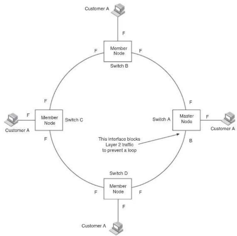
flowchart
graph TD
A["Customer A"] -->|F| B["Member Node"]
B -->|F| C["Switch B"]
C -->|F| D["Master Node"]
D -->|F| E["Switch A"]
E -->|F| F["Customer A"]
F -->|F| G["Member Node"]
G -->|F| H["Switch C"]
H -->|F| I["Member Node"]
I -->|F| J["Switch D"]
J -->|F| K["Member Node"]
K -->|F| L["Switch C"]
L -->|F| M["Member Node"]
M -->|F| N["Switch D"]
N -->|F| O["Member Node"]
O -->|F| P["Switch C"]
P -->|F| Q["Member Node"]
Q -->|F| R["Switch D"]
R -->|F| S["Member Node"]
S -->|F| T["Switch C"]
T -->|F| U["Member Node"]
U -->|F| V["Switch D"]
V -->|F| W["Member Node"]
W -->|F| X["Switch C"]
X -->|F| Y["Member Node"]
Y -->|F| Z["Switch D"]
Z -->|F| AA["Member Node"]
AA -->|F| AB["Switch C"]
AB -->|F| AC["Member Node"]
AC -->|F| AD["Switch D"]
AD -->|F| AE["Member Node"]
AE -->|F| AF["Switch C"]
AF -->|F| AG["Member Node"]
AG -->|F| AH["Switch D"]
AH -->|F| AI["Member Node"]
AI -->|F| AJ["Switch C"]
AJ -->|F| AK["Member Node"]
AK -->|F| AL["Switch D"]
AL -->|F| AM["Member Node"]
AM -->|F| AN["Switch C"]
AN -->|F| AO["Member Node"]
AO -->|F| AP["Switch D"]
AP -->|F| AQ["Member Node"]
AQ -->|F| AR["Switch C"]
AR -->|F| AS["Member Node"]
AS -->|F| AT["Switch D"]
AT -->|F| AU["Member Node"]
AU -->|F| AV["Switch C"]
AV -->|F| AW["Member Node"]
AW -->|F| AX["Switch D"]
AX -->|F| AY["Member Node"]
AY -->|F| AZ["Switch C"]
AZ -->|F| BA["Member Node"]
BA -->|F| BB["Switch D"]
BB -->|F| BC["Member Node"]
BC -->|F| BD["Switch C"]
BD -->|F| BE["Member Node"]
BE -->|F| BF["Switch D"]
BF -->|F| BG["Member Node"]
BG -->|F| BH["Switch C"]
BH -->|F| BI["Member Node"]
BI -->|F| BJ["Switch D"]
BJ -->|F| BK["Member Node"]
BK -->|F| BL["Switch C"]
BL -->|F| BM["Member Node"]
BM -->|F| BN["Switch D"]
BN -->|F| BO["Member Node"]
BO -->|F| BP["Switch C"]
BP -->|F| BQ["Member Node"]
BQ -->|F| BR["Switch D"]
BR -->|F| BS["Member Node"]
BS -->|F| BT["Switch C"]
BT -->|F| BU["Member Node"]
BU -->|F| BV["Switch D"]
BV -->|F| BW["Member Node"]
BW -->|F| BX["Switch C"]
BX -->|F| BY["Member Node"]
BY -->|F| BZ["Member Node"]
The ring in this example consists of four MRP nodes (Brocade switches). Each node has two interfaces with the ring. Each node also is connected to a separate customer network. The nodes forward Layer 2 traffic to and from the customer networks through the ring. The ring interfaces are all in one port-based VLAN. Each customer interface can be in the same VLAN as the ring or in a separate VLAN.
One node, is configured as the master node of the MRP ring. One of the two interfaces on the master node is configured as the primary interface; the other is the secondary interface. The primary interface originates Ring Health Packets (RHPs), which are used to monitor the health of the ring. An RHP is forwarded on the ring to the next interface until it reaches the secondary interface of the master node. The secondary interface blocks the packet to prevent a Layer 2 loop.
NOTE
When you configure MRP, Brocade recommends that you disable one of the ring interfaces before beginning the ring configuration. Disabling an interface prevents a Layer 2 loop from occurring while you are configuring MRP on the ring nodes. Once MRP is configured and enabled on all the nodes, you can re-enable the interface.
MRP rings without shared interfaces
MRP Phase 1 allows you to configure multiple MRP rings, as shown in Figure 64, but the rings cannot share the same link. For example, you cannot configure ring 1 and ring 2 to each have interfaces 1/1 and 1/2.
Also, when you configured an MRP ring, any node on the ring that can be designated as the master node for the ring. A master node can be the master node of more than one ring. (Refer to Figure 64.) Each ring is an independent ring and RHP packets are processed within each ring.
FIGURE 64 Metro ring - multiple rings

flowchart
graph TD
A["Master Node"] --> B["Ring 1"]
B --> C["Port 1/1"]
B --> D["Port 1/2"]
B --> E["Port 4/1"]
B --> F["Port 4/2"]
G["Ring 2"] --> H["Master node"]
H --> I["Ring 3"]
I --> J["Port 1/1"]
I --> K["Port 1/2"]
I --> L["Port 4/1"]
I --> M["Port 4/2"]
In this example, two nodes are each configured with two MRP rings. Any node in a ring can be the master for its ring. A node also can be the master for more than one ring.
Ring initialization
The ring shown in Figure 63 shows the port states in a fully initialized ring without any broken links. Figure 65 shows the initial state of the ring, when MRP is first enabled on the ring's switches. All ring interfaces on the master node and member nodes begin in the Preforwarding state (PF).
FIGURE 65 Metro ring – initial state

flowchart
graph TD
A["Customer A"] -->|F| B["Switch B"]
B -->|PF PF| C["Switch C"]
C -->|PF| D["Switch D"]
D -->|PF| E["Master Node"]
E -->|F| F["Customer A"]
F -->|F| G["Switch C"]
G -->|PF| H["Switch D"]
H -->|PF| I["Switch C"]
I -->|PF| J["Switch B"]
J -->|PF| K["Switch C"]
K -->|PF| L["Switch D"]
L -->|PF| M["Switch C"]
M -->|PF| N["Switch B"]
N -->|PF| O["Switch C"]
O -->|PF| P["Switch D"]
P -->|PF| Q["Switch C"]
Q -->|PF| R["Switch B"]
R -->|PF| S["Switch C"]
S -->|PF| T["Switch D"]
T -->|PF| U["Switch C"]
U -->|PF| V["Switch B"]
V -->|PF| W["Switch C"]
W -->|PF| X["Switch D"]
X -->|PF| Y["Switch C"]
Y -->|PF| Z["Switch B"]
Z -->|PF| AA["Switch C"]
AA -->|PF| AB["Switch D"]
AB -->|PF| AC["Switch C"]
AC -->|PF| AD["Switch B"]
AD -->|PF| AE["Switch C"]
AE -->|PF| AF["Switch D"]
AF -->|PF| AG["Switch C"]
AG -->|PF| AH["Switch B"]
AH -->|PF| AI["Switch C"]
AI -->|PF| AJ["Switch D"]
AJ -->|PF| AK["Switch C"]
AK -->|PF| AL["Switch B"]
AL -->|PF| AM["Switch C"]
AM -->|PF| AN["Switch D"]
AN -->|PF| AO["Switch C"]
AO -->|PF| AP["Switch B"]
AP -->|PF| AQ["Switch C"]
AQ -->|PF| AR["Switch D"]
AR -->|PF| AS["Switch C"]
AS -->|PF| AT["Switch B"]
AT -->|PF| AU["Switch C"]
AU -->|PF| AV["Switch D"]
AV -->|PF| AW["Switch C"]
AW -->|PF| AX["Switch B"]
AX -->|PF| AY["Switch C"]
AY -->|PF| AZ["Switch D"]
AZ -->|PF| BA["Switch C"]
BA -->|PF| BB["Switch D"]
BB -->|PF| BC["Switch C"]
BC -->|PF| BD["Switch B"]
BD -->|PF| BE["Switch C"]
BE -->|PF| BF["Switch D"]
BF -->|PF| BG["Switch C"]
BG -->|PF| BH["Switch B"]
BH -->|PF| BI["Switch C"]
BI -->|PF| BJ["Switch D"]
BJ -->|PF| BK["Switch C"]
BK -->|PF| BL["Switch B"]
BL -->|PF| BM["Switch C"]
BM -->|PF| BN["Switch D"]
BN -->|PF| BO["Switch C"]
BO -->|PF| BP["Switch B"]
BP -->|PF| BQ["Switch C"]
BQ -->|PF| BR["Switch D"]
BR -->|PF| BS["Switch C"]
BS -->|PF| BT["Switch B"]
BT -->|PF| BU["Switch C"]
BU -->|PF| BV["Switch D"]
BV -->|PF| BW["Switch C"]
BW -->|PF| BX["Switch B"]
BX -->|PF| BY["Switch C"]
BY -->|PF| BZ["Switch D"]
BZ -->|PF| CA["Switch C"]
CA -->|PF| CB["Switch B"]
CB -->|PF| CC["Switch C"]
CC -->|PF| CD["Switch D"]
CD -->|PF| CE["Switch C"]
CE -->|PF| CF["Switch B"]
CF -->|PF| CG["Switch C"]
CG -->|PF| CH["Switch D"]
CH -->|PF| CI["Switch C"]
CI -->|PF| CJ["Switch B"]
CJ -->|PF| CK["Switch C"]
CK -->|PF| CR["Switch D"]
CR -->|PF| CS["Switch C"]
CS -->|PF| CT["Switch B"]
CT -->|PF| CU["Switch C"]
CU -->|PF| CV["Switch D"]
CV -->|PF| DW["Switch C"]
DW -->|PF| CX["Switch B"]
CX -->|PF| CY["Switch C"]
CY -->|PF| CZ["Switch D"]
MRP uses Ring Health Packets (RHPs) to monitor the health of the ring. An RHP is an MRP protocol packet. The source address is the MAC address of the master node and the destination MAC address is a protocol address for MRP. The Master node generates RHPs and sends them on the ring. The state of a ring port depends on the RHPs.
A ring interface can have one of the following MRP states:
- Preforwarding (PF) – The interface can forward RHPs but cannot forward data. All ring ports being in this state when you enable MRP.
- Forwarding (F) – The interface can forward data as well as RHPs. An interface changes from Preforwarding to Forwarding when the port's preforwarding time expires. This occurs if the port does not receive an RHP from the Master, or if the forwarding bit in the RHPs received by the port is off. This indicates a break in the ring. The port heals the ring by changing its state to Forwarding. The preforwarding time is the number of milliseconds the port will remain in the Preforwarding state before changing to the Forwarding state, even without receiving an RHP.
- Blocking (B) – The interface can process RHPs, but cannot forward data. Only the secondary interface on the Master node can be Blocking.
When MRP is enabled, all ports begin in the Preforwarding state. The primary interface on the Master node, although it is in the Preforwarding state like the other ports, immediately sends an RHP onto the ring. The secondary port on the Master node listens for the RHP.
- If the secondary port receives the RHP, all links in the ring are up and the port changes its state to Blocking. The primary port then sends another MRP with its forwarding bit set on. As each of the member ports receives the RHP, the ports changes their state to Forwarding. Typically, this occurs in sub-second time. The ring very quickly enters the fully initialized state.
- If the secondary port does not receive the RHP by the time the preforwarding time expires, a break has occurred in the ring. The port changes its state to Forwarding. The member ports also change their states from Preforwarding to Forwarding as their preforwarding timers expire. The ring is not intact, but data can still travel among the nodes using the links that are up.
Figure 66 shows an example.
FIGURE 66 Metro ring – from Preforwarding to Forwarding
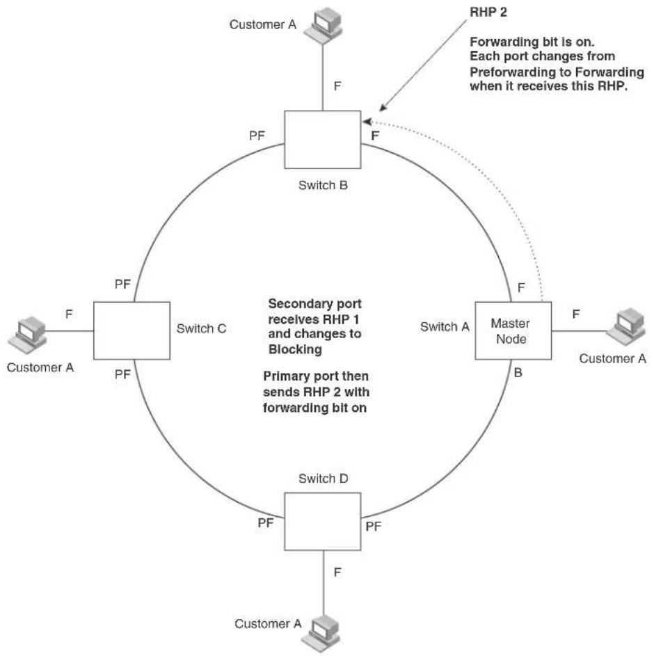
flowchart
graph TD
A["Customer A"] -->|F| B["Switch B"]
B -->|F| C["Switch C"]
C -->|F| D["Switch D"]
D -->|F| E["Master Node"]
E -->|F| F["Customer A"]
G["RHP 2"] -->|Forwarding bit is on. Each port changes from Preforwarding to Forwarding when it receives this RHP.| B
style A fill:#f9f,stroke:#333
style F fill:#f9f,stroke:#333
style G fill:#ccf,stroke:#333
style H fill:#cfc,stroke:#333
note right of B: Secondary port receives RHP 1 and changes to Blocking
note right of D: Primary port then sends RHP 2 with forwarding bit on
Each RHP also has a sequence number. MRP can use the sequence number to determine the round-trip time for RHPs in the ring. Refer to “MRP phase 2” on page 412.
How ring breaks are detected and healed
Figure 67 Shows the ring forwarding state following a link break. MRP quickly heals the ring and preserves connectivity among the customer networks.
FIGURE 67 Metro ring - ring break

flowchart
graph TD
A["Customer A"] -->|F| B["Switch B"]
B -->|F| C["Switch C"]
C -->|F| D["Switch A"]
D -->|F| E["Master Node"]
E -->|F| F["Customer A"]
F -->|F| G["Switch D"]
G -->|F| H["Customer A"]
H -->|F| I["Switch B"]
I -->|F| J["Switch C"]
J -->|F| K["Switch A"]
If a break in the ring occurs, MRP heals the ring by changing the states of some of the ring interfaces:
- Blocking interface – The Blocking interface on the Master node has a dead timer. If the dead time expires before the interface receives one of its ring's RHPs, the interface changes state to Preforwarding. Once the secondary interface changes state to Preforwarding:
- If the interface receives an RHP, the interface changes back to the Blocking state and resets the dead timer.
- If the interface does not receive an RHP for its ring before the Preforwarding time expires, the interface changes to the Forwarding state, as shown in Figure 67.
- Forwarding interfaces – Each member interface remains in the Forwarding state.
When the broken link is repaired, the link's interfaces come up in the Preforwarding state, which allows RHPs to travel through the restored interfaces and reach the secondary interface on the Master node.
- If an RHP reaches the Master node's secondary interface, the ring is intact. The secondary interface changes to Blocking. The Master node sets the forwarding bit on in the next RHP. When the restored interfaces receive this RHP, they immediately change state to Forwarding.
- If an RHP does not reach the Master node's secondary interface, the ring is still broken. The Master node does not send an RHP with the forwarding bit on. In this case, the restored interfaces remain in the Preforwarding state until the preforwarding timer expires, then change to the Forwarding state.
Foundry MRP alarm RHP enhancement
Previously, detection of Foundry MRP ring breaks was completely timer based. An absence of Ring Health Packets (RHP) for a period of 3 “hello times” indicated to the Foundry MRP master that the ring is broken. This initiated the transition to a topology change as described in the previous section. The convergence time associated with such an event could take several hundreds of milliseconds.
Now, each Foundry MRP node is made a more active participant in detecting link failures. When a link is detected to be down by its “downstream” neighbor, a special packet (called the Alarm RHP packet) is sent to the Foundry MRP master, indicating that the link is down.
This Foundry MRP packet is sent from the Foundry MRP member to the Foundry MRP master only when the secondary link goes down and it is sent on the primary link. The destination MAC address in the packet is the ring MAC address. This allows the packet to be hardware forwarded all the way to the Foundry MRP master. When the Master switch in the ring receives this packet, it is notified of a break in the ring. At that point, the secondary interface is immediately transitioned from "Blocked" to "Forwarding".
NOTE
The Alarm RHP packet is only sent by the secondary link owner ring to prevent multiple Foundry MRP masters going into forward where shared rings are configured.
Operation of foundry MRP alarm RHP enhancement
Operation of the Foundry MRP Alarm RHP enhancement is described in Figure 68 and in the following:
When the link between Switch B and Switch C fails, the "downstream" neighbor (Switch C) detects the failure of the link and triggers corrective action. The following is the complete sequence of events that occurs.
- The downstream neighbor (Switch C) detects a link down event of the link between Switch B and Switch C
- Switch C sends a single RHP packet with a special Alarm bit set. The RHP packet is sent in the same direction of flow as that of the normal RHP packets (i.e. on the link to Switch D)
- Switch A receives the special RHP packet (on the secondary interface) that was sent by Switch C. It is now aware that the ring is broken even though the dead_interval may not have expired.
-
Switch A immediately transitions its secondary interface (previously in Blocked state) to the Forwarding state.
-
RHP packets continue to be sent on the primary interface by Switch A to detect if the ring has been healed.
From a user perspective, there is no difference in the behavior of the ring. The only noticeable difference is a rapid convergence in the event of ring failure. There is no CLI command required to enable this feature.
FIGURE 68 A Foundry MRP ring under normal operation (A) and after detection of a failure in the ring (B)

flowchart
graph TD
A["Master"] -->|Forwarding Blocked| B["RHP packet direction"]
B --> C["Switch C"]
C --> D["Switch D"]
D --> E["Switch E"]
E --> A
style A fill:#f9f,stroke:#333
style B fill:#ccf,stroke:#333
style C fill:#cfc,stroke:#333
style D fill:#fcc,stroke:#333
style E fill:#cff,stroke:#333
(a)

flowchart
graph TD
A["Master"] -->|Forwarding| B["Switch A"]
B --> C["Switch B"]
C --> D["Switch D"]
D --> E["Switch E"]
E --> A
C --> F["Alarm RHP packet"]
F --> D
(b)
Master VLANs and customer VLANs in a topology group
All the ring ports must be in the same VLAN. Placing the ring ports in the same VLAN provides Layer 2 connectivity for a given customer across the ring. Figure 69 shows an example.
FIGURE 69 Metro ring - ring VLAN and customer VLANs

flowchart
graph TD
SwitchB["Switch B"] -->|ring 1: interfaces 1/1, 1/2, topology group 2: master VLAN 2 (1/1, 1/2), member VLAN 30 (1/1, 1/2, 2/1), member VLAN 40 (1/1, 1/2, 4/1)| SwitchD["Switch D"]
SwitchB -->|port2/1: port1/2: port1/1: port4/1: port1/1: port4/1: port1/1: port4/1: port4/1: port4/1: port4/1: port4/1: port4/1: port4/1: port4/1: port4/1: port4/1: port4/1: port4/1: port4/1: port4/1: port4/1: port4/1: port4/1: port4/1: port4/1: port4/1: port5| SwitchB
SwitchB -->|Customer A: VLAN 30| SwitchB
SwitchB -->|Customer B: VLAN 40| SwitchB
SwitchB -->|Customer C: VLAN 30| SwitchB
SwitchB -->|Customer D: VLAN 30| SwitchB
SwitchB -->|Customer E: VLAN 40| SwitchB
SwitchB -->|Customer F: VLAN 30| SwitchB
SwitchB -->|Customer G: VLAN 40| SwitchB
SwitchB -->|Customer H: VLAN 30| SwitchB
SwitchB -->|Customer I: VLAN 30| SwitchB
SwitchB -->|Customer J: VLAN 40| SwitchB
SwitchB -->|Customer K: VLAN 30| SwitchB
SwitchB -->|Customer L: VLAN 40| SwitchB
SwitchB -->|Customer M: VLAN 30| SwitchB
SwitchB -->|Customer N: VLAN 30| SwitchB
SwitchB -->|Customer O: VLAN 40| SwitchB
SwitchB -->|Customer P: VLAN 30| SwitchB
SwitchB -->|Customer Q: VLAN 40| SwitchB
SwitchB -->|Customer R: VLAN 30| SwitchB
SwitchB -->|Customer S: VLAN 30| SwitchB
SwitchB -->|Customer T: VLAN 40| SwitchB
SwitchB -->|Customer U: VLAN 30| SwitchB
SwitchB -->|Customer V: VLAN 40| SwitchB
Notice that each customer has their own VLAN. Customer A has VLAN 30 and Customer B has VLAN 40. Customer A's host attached to Switch D can reach the Customer A host attached to Switch B at Layer 2 through the ring. Since Customer A and Customer B are on different VLANs, they will not receive each other's traffic.
You can configure MRP separately on each customer VLAN. However, this is impractical if you have many customers. To simplify configuration when you have a lot of customers (and therefore a lot of VLANs), you can use a topology group.
A topology group enables you to control forwarding in multiple VLANs using a single instance of a Layer 2 protocol such as MRP. A topology group contains a master VLAN and member VLANs. The master VLAN contains all the configuration parameters for the Layer 2 protocol (STP, MRP, or VSRP). The member VLANs use the Layer 2 configuration of the master VLAN.
In Figure 69, VLAN 2 is the master VLAN and contains the MRP configuration parameters for ring 1. VLAN 30 and VLAN 40, the customer VLANs, are member VLANs in the topology group. Since a topology group is used, a single instance of MRP provides redundancy and loop prevention for both the customer VLANs.
If you use a topology group:
- The master VLAN must contain the ring interfaces. The ports must be tagged, since they will be shared by multiple VLANs.
- The member VLAN for a customer must contain the two ring interfaces and the interfaces for the customer. Since these interfaces are shared with the master VLAN, they must be tagged. Do not add another customer's interfaces to the VLAN.
- When configuring a topology group on a port, note the following:
- A topology group must be configured before configuring a Layer 2 protocol in the master VLAN.
- The port should be disabled before configuring a topology group on that port.
• There should not be traffic on the port before configuring a topology group on that port.
For more information about topology groups, refer to Chapter 16, "Topology Groups".
Refer to “MRP CLI example” on page 421 for the configuration commands required to implement the MRP configuration shown in Figure 69.
Configuring MRP
To configure MRP, perform the following tasks. You need to perform the first task on only one of the nodes. Perform the remaining tasks on all the nodes:
- Disable one of the ring interfaces. This prevents a Layer 2 loop from occurring while you are configuring the devices for MRP.
- Add an MRP ring to a port-based VLAN. When you add a ring, the CLI changes to the configuration level for the ring, where you can do the following:
- Optionally, specify a name for the ring.
- On the master node only, enable the device to be the master for the ring. Each ring can have only one master node.
- Specify the MRP interfaces. Each device has two interfaces to an MRP ring.
- Optionally, change the hello time and the preforwarding time. These parameters control how quickly failover occurs following a change in the state of a link in the ring.
- Enable the ring.
- Optionally, add the ring's VLAN to a topology group to add more VLANs to the ring. If you use a topology group, make sure you configure MRP on the group's master VLAN. Refer to Chapter 16, "Topology Groups".
- Re-enable the interface you disabled to prevent a Layer 2 loop. Once MRP is enabled, MRP will prevent the Layer 2 loop.
NOTE
When MRP and UDLD are running together, Brocade recommends keeping the MRP preforwarding interval slightly higher than default(300ms) to 400 or 500ms to prevent the possibility of a temporary loop of a few milliseconds.
Adding an MRP ring to a VLAN
NOTE
If you plan to use a topology group to add VLANs to the ring, make sure you configure MRP on the topology group's master VLAN.
To add an MRP ring to a VLAN, enter commands such as the following.
BigIron RX(config)# vlan 2
BigIron RX(config-vlan-2)# metro-ring 1
BigIron RX(config-vlan-2-mrp-1)# name CustomerA
BigIron RX(config-vlan-2-mrp-1)# master
BigIron RX(config-vlan-2-mrp-1)# ring-interface ethernet 1/1 ethernet 1/2
BigIron RX(config-vlan-2-mrp-1)# enable
These commands configure an MRP ring on VLAN 2. The ring ID is 1, the ring name is CustomerA, and this node (this device) is the master for the ring. The ring interfaces are 1/1 and 1/2. Interface 1/1 is the primary interface and 1/2 is the secondary interface. The primary interface will initiate RHPs by default. The ring takes effect in VLAN 2.
Syntax: [no]metro-ring
The
Syntax: [no]name
The
Syntax: [no] master
Configures this node as the master node for the ring. Enter this command only on one node in the ring. The node is a member (non-master) node by default.
Syntax: [no] ring-interface ethernet
The ethernet
The ethernet
You can use two Ethernet interfaces.
NOTE
To take advantage of every interface in a Metro network, you can configure another MRP ring and either configure a different Master node for the ring or reverse the configuration of the primary and secondary interfaces on the Master node. Configuring multiple rings enables you to use all the ports in the ring. The same port can forward traffic one ring while blocking traffic for another ring.
Syntax: [no] enable
The enable command enables the ring.
Changing the hello and preforwarding times
You also can change the RHP hello time and preforwarding time. To do so, enter commands such as the following.
BigIron RX(config-vlan-2-mrp-1)# hello-time 200
BigIron RX(config-vlan-2-mrp-1)# preforwarding-time 400
These commands change the hello time to 200 ms and change the preforwarding time to 400 ms.
NOTE
The preforwarding time must be at least twice the value of the hello time and must be a multiple of the hello time.
Syntax: [no] hello-time
Syntax: [no] preforwarding-time
The
The hello time can be from 100 - 1000 (one second). The default hello time is 100 ms.
The preforwarding time can be from 200 - 5000 ms, but must be at least twice the value of the hello time and must be a multiple of the hello time. The default preforwarding time is 300 ms.
A change to the hello time or preforwarding time takes effect as soon as you enter the command.
NOTE
You can use MRP ring diagnostics to determine whether you need to change the hello time and preforwarding time. Refer to “MRP phase 2”.
MRP phase 2
Metro Ring Protocol (MRP) Phase 2 expands the functionality of MRP by allowing a physical interface that belong to the same VLAN to be shared by multiple rings.
MRP is a Brocade proprietary protocol that prevents Layer 2 loops and provides fast reconvergence in Layer 2 ring topologies. It is an alternative to STP and is especially useful in Metropolitan Area Networks (MANs) that require more nodes and faster reconvergence time than what STP provides.
An MRP ring consists of nodes and each node has two interfaces on the ring. The interfaces on the ring must be members of the same port-based VLAN. Each node on the ring is connected to a separate customer network. The nodes forward Layer 2 traffic to and from the customer networks through the ring.
One node, is configured as the master node of the MRP ring. One of the two interfaces on the master node is configured as the primary interface; the other is the secondary interface. The primary interface originates Ring Health Packets (RHPs), which are used to monitor the health of the ring. An RHP is forwarded on the ring to the next interface until it reaches the secondary interface of the master node. The secondary interface blocks the packet to prevent a Layer 2 loops.
In MRP Phase 1, a node can have multiple MRP rings, but the rings cannot share the same interface. Also, when you configured an MRP ring, any node on the ring that is a device can be designated as the master node for the ring. Each ring is an independent ring and RHP packets are processed within each ring.
FIGURE 70 Multiple MRP rings - MRP Phase 1

flowchart
graph TD
A["Master Node"] --> B["Ring 1"]
B --> C["Port 1/1"]
B --> D["Port 1/2"]
B --> E["Port 4/1"]
B --> F["Port 4/2"]
G["Ring 2"] --> H["Master node"]
H --> I["Port 3"]
H --> J["Port 3"]
H --> K["Port 3"]
style A fill:#f9f,stroke:#333
style B fill:#ccf,stroke:#333
style G fill:#cfc,stroke:#333
style H fill:#fcc,stroke:#333
style I fill:#cff,stroke:#333
style J fill:#ffc,stroke:#333
style K fill:#fcc,stroke:#333
With MRP Phase 2, MRP rings can be configured to share the same interfaces as long as the interfaces belong to the same VLAN. Figure 70 shows examples of multiple MRP rings that share the same interface.
FIGURE 71 Example of multiple rings sharing the same interface - MRP Phase2

flowchart
graph TD
subgraph Example 1 Example 2
A["Node"] --> B["Ring 1"]
B --> C["Port 1/1 VLAN 2"]
C --> D["Ring 2"]
D --> E["Node"]
F["Node"] --> G["Ring 1"]
G --> H["Port 1/1 VLAN 2"]
H --> I["Ring 2"]
I --> J["Node"]
K["Node"] --> L["Ring 1"]
L --> M["Port 1/1 VLAN 2"]
M --> N["Ring 2"]
N --> O["Node"]
P["Node"] --> Q["Ring 1"]
Q --> R["Port 1/1 VLAN 2"]
R --> S["Ring 2"]
S --> T["Node"]
U["Node"] --> V["Ring 1"]
V --> W["Port 1/1 VLAN 2"]
W --> X["Ring 2"]
X --> Y["Node"]
Z["Node"] --> AA["Ring 1"]
AA --> AB["Port 1/1 VLAN 2"]
AB --> AC["Ring 2"]
AC --> AD["Node"]
AE["Node"] --> AF["Ring 1"]
AF --> AG["Port 1/1 VLAN 2"]
AG --> AH["Ring 2"]
AH --> AI["Node"]
AJ["Node"] --> AK["Ring 1"]
AK --> AL["Port 1/1 VLAN 2"]
AL --> AM["Ring 2"]
AM --> AN["Node"]
AO["Node"] --> AP["Ring 1"]
AP --> AQ["Port 1/1 VLAN 2"]
AQ --> AR["Ring 2"]
AR --> AS["Node"]
AT["Node"] --> AU["Ring 1"]
AU --> AV["Port 1/1 VLAN 2"]
AV --> AW["Ring 2"]
AW --> AX["Node"]
AY["Node"] --> AZ["Ring 1"]
AZ --> BA["Port 1/1 VLAN 2"]
BA --> BB["Ring 2"]
BB --> BC["Node"]
BD["Node"] --> BE["Ring 1"]
BE --> BF["Port 1/1 VLAN 2"]
BF --> BG["Ring 2"]
BG --> BH["Node"]
BI["Node"] --> BJ["Ring 1"]
BJ --> BK["Port 1/1 VLAN 2"]
BK --> BL["Ring 2"]
BL --> BM["Node"]
BN["Node"] --> BO["Ring 1"]
BO --> BP["Port 1/1 VLAN 2"]
BP --> BQ["Ring 2"]
BQ --> BR["Node"]
BS["Node"] --> BT["Ring 1"]
BT --> BU["Port 1/1 VLAN 2"]
BU --> BV["Ring 2"]
BV --> BW["Node"]
BX["Node"] --> BY["Ring 1"]
BY --> BZ["Port 1/1 VLAN 2"]
BZ --> CA["Ring 2"]
CA --> CB["Node"]
On each node that will participate in the ring, you specify the ring's ID and the interfaces that will be used for ring traffic. In a multiple ring configuration, a ring's ID determines its priority. The lower the ring ID, the higher priority of a ring.
A ring's ID is also used to identify the interfaces that belong to a ring.
Ring initialization for shared interfaces
FIGURE 72 Interface IDs and types

flowchart
graph TD
A["Computer"] --> B["Ring 1"]
B --> C["S1"]
C --> D["Port 1/1"]
C --> E["Port 2/2"]
C --> F["S2"]
F --> G["Port 2"]
F --> H["Computer"]
style A fill:#f9f,stroke:#333
style B fill:#ccf,stroke:#333
style C fill:#cfc,stroke:#333
style D fill:#fcc,stroke:#333
style E fill:#cff,stroke:#333
style F fill:#ffc,stroke:#333
style G fill:#cfc,stroke:#333
style H fill:#fcc,stroke:#333
note right of C: C = customer port
For example, in Figure 72, the ID of all interfaces on all nodes on Ring 1 is 1 and all interfaces on all nodes on Ring 2 is 2. Port 1/1 on node S1 and Port 2/2 on S2 have the IDs of 1 and 2 since the interfaces are shared by Rings 1 and 2.
The ring's ID is also used to determine an interface's priority. Generally, a ring's ID is also the ring's priority and the priority of all interfaces on that ring. However, if the interface is shared by two or more rings, then the highest priority (lowest ID) becomes the priority of the interface. For example, in Figure 72, all interfaces on Ring 1, except for Port 1/1 on node S1 and Port 2/2 on node S2 have a priority of 1. Likewise, all interfaces on Ring 2, except for Port 1/1 on node S1 and Port 2/2 on node S2 have a priority of 2. Port 1/1 on S1 and Port 2/2 on S2 have a priority of 1 since 1 is the highest priority (lowest ID) of the rings that share the interface.
If a node has interfaces that have different IDs, the interfaces that belong to the ring with the highest priority become regular ports. Those interfaces that do not belong to the ring with the highest priority become tunnel ports. In Figure 72, nodes S1 and S2 have interfaces that belong to Rings 1 and 2. Those interfaces with a priority of 1 are regular ports. The interfaces with a priority of 2 are the tunnel ports since they belong to Ring 2, which has a lower priority than Ring 1.
How ring breaks are detected and healed between shared interfaces
If the link between shared interfaces breaks, the secondary interface on Ring 1's master node changes to a preforwarding state. The RHP packet sent by port 3/1 on Ring 2 is forwarded through the interfaces on S4, then to S2. The packet is then forwarded through S2 to S3, but not from S2 to S1 since the link between the two nodes is not available. When the packet reaches Ring 1's master
node, the packet is forwarded through the secondary interface since it is currently in a preforwarding state. A secondary interface in preforwarding mode ignores any RHP packet that is not from its ring. The secondary interface changes to blocking mode only when the RHP packet forwarded by its primary interface is returned.
The packet then continues around Ring 1, through the interfaces on S1 to Ring 2 until it reaches Ring 2's master node. Port 3/2, the secondary interface on Ring 2 changes to blocking mode since it received its own packet, then blocks the packet to prevent a loop.
NOTE
On the ring member node, the primary and secondary interface is not only decided by the configuration, but also decide by the RHP flow from the ring master. The primary and secondary interface may not be swapped even if the configuration changes and there is an active ring master in the topology. If there is no active ring master in the topology, then the running configuration of the interface on the member node will follow what was configured.
Selection of master node
Allowing MRP rings to share interfaces limits the nodes that can be designated as the master node. Any node on an MRP ring that does not have a shared interface can be designated as the ring's master node. However, if all nodes on the ring have shared interfaces, nodes that do not have tunnel ports can be designated as the master node of that ring. If none of the nodes meet these criteria, you must change the rings' priorities by reconfiguring the rings' ID.
In Figure 72, any of the nodes on Ring 1, even S1 or S2, can be a master node since none of its interfaces are tunnel ports. However in Ring 2, neither S1 nor S2 can be a master node since these nodes contain tunnel ports.
RHP processing in rings with shared interfaces
Interfaces on an MRP ring have one of the following states:
- Preforwarding (PF) – All ring interfaces are in this state when you enable MRP.
- Forwarding (F) – An interface changes from Preforwarding to Forwarding when the port's preforwarding time expires.
- Blocking (B) – The interface cannot forward data. Only the secondary interface on the Master node can be Blocking.
The primary interface of the master node initiates the RHP packets and sends it on the ring. When the packet reaches an interface, MRP checks to see if the receiving interface is a regular port or a tunnel port.
If the port is a regular port, the RHP packet is forwarded to the next interface. Forwarding of the packet continues on the ring until the secondary interface of the master node receives the packet and blocks it.
If the port is a tunnel port, MRP checks the priority of the RHP packet and compares it to the priority of the tunnel port:
- If the RHP packet's priority is less than or equal to the interface's priority, the packet is forwarded through that interface.
- If the priority of the RHP packet is greater than the priority of the interface, the RHP packet is dropped.
Normal flow
Figure 73 shows an example of how RHP packets are processed normally in MRP rings with shared interfaces.
FIGURE 73 Flow of RHP packets on MRP rings with shared interfaces

flowchart
graph TD
subgraph Ring 1
S1[" "] -->|1| S2[" "]
S2 -->|1,2| S3[" "]
S3 -->|1| S4[" "]
S4 -->|2| S1
end
subgraph Ring 2
S1 -->|2| S2
S2 -->|2| S3
S3 -->|2| S4
S4 -->|2| S1
end
Note: Master node (primary interface) and secondary interface port2/1 are labeled on the Ring 1 and Ring 2 respectively. The diagram shows connections between nodes and interfaces.
-
-
-
-
-
-
-
-
-
- = Ring 1 RHP packet
-
-
-
-
-
-
-
-
- . . . . . . . - - - - = Ring 2 RHP packet
Port 2/1 on Ring 1's master node is the primary interface of the master node. The primary interface forwards an RHP packet on the ring. Since all the interfaces on Ring 1 are regular ports, the RHP packet is forwarded to all the interfaces until it reaches Port 2/2, the secondary interface of the master node. Port 2/2 then blocks the packet to complete the process.
On Ring 2, Port 3/1, is the primary interface of the master node. It sends an RHP packet on the ring. Since all ports on S4 are regular ports, the RHP packet is forwarded on those interfaces. When the packet reaches S2, the receiving interface is a tunnel port. The port compares the packet's priority to its priority. Since the packet's priority is the same as the tunnel port's priority, the packet is forwarded up the link shared by Rings 1 and 2.
When the RHP packet reaches the interface on node S2 shared by Rings 1 and 2, the packet is forwarded since its priority is less than the interface's priority. The packet continues to be forwarded to node S1 until it reaches the tunnel port on S1. That tunnel port determines that the RHP packet's priority is equal to the port's priority and forwards the packet. The RHP packet is forwarded to the remaining interfaces on Ring 2 until it reaches port 3/2, the secondary interface of the master node. Port 3/2 then blocks the packet to prevent a loop.
When the RHP packet from Ring 2 reached S2, it was also forwarded from S2 to S3 on Ring 1 since the port on S2 has a higher priority than the RHP packet. The packets is forwarded around Ring 1 until it reaches port 2/2, Ring 1's the secondary port. The RHP packet is then blocked by that port.
Flow when a link breaks
If the link between shared interfaces breaks (Figure 74), the secondary interface on Ring 1's master node changes to a preforwarding state. The RHP packet sent by port 3/1 on Ring 2 is forwarded through the interfaces on S4, then to S2. The packet is then forwarded through S2 to S3, but not from S2 to S1 since the link between the two nodes is not available. When the packet reaches Ring 1's master node, the packet is forwarded through the secondary interface since it is currently in a preforwarding state. A secondary interface in preforwarding mode ignores any RHP packet that is not from its ring. The secondary interface changes to blocking mode only when the RHP packet forwarded by its primary interface is returned.
The packet then continues around Ring 1, through the interfaces on S1 to Ring 2 until it reaches Ring 2's master node. Port 3/2, the secondary interface on Ring 2 changes to blocking mode since it received its own packet, then blocks the packet to prevent a loop.
FIGURE 74 Flow of RHP packets when a link for shared interfaces brakes

flowchart
```mermaid
graph TD
subgraph Ring 1
S1["Master node (primary interface) port2/1"] -->|1| S3["Master node"]
S1 -->|1,2| S2["Master node"]
S2 -->|1,2| S4["Master node"]
S2 -->|2| S1
end
subgraph Ring 2
S1 -->|2| S4
S2 -->|2| S4
S3 -->|1| S1
S4 -->|2| S1
S1 -->|2| Port3/2["Port3/2"]
S2 -->|2| Port3/1["Port3/1"]
end
Note: "port2/2 changes to preforwarding" is shown on the left edge of Ring 1. Dotted arrows indicate flow or routing between nodes. Nodes are connected via solid and dotted lines to each ring.
. . . . . . ▶ = Ring 2 RHP packet
RHP packets follow this flow until the link is restored; then the RHP packet returns to it normal flow as shown in Figure 74.
NOTE
There should always be a layer 2 protocol configured in the default VLAN when MRP is configured with all dual mode ports.
Configuring MRP with shared interfaces
MRP Phase 2 allows you to enter commands such as the following when configuring MRP.
BigIron RX(config)# vlan 2
BigIron RX(config-vlan-2)# metro-ring 1
BigIron RX(config-vlan-2-mrp-1)# name CustomerA
BigIron RX(config-vlan-2-mrp-1)# ring-interface ethernet 1/1 ethernet 1/2
BigIron RX(config-vlan-2-mrp-1)# enable
BigIron RX(config-vlan-2-mrp-1)# metro-ring 2
BigIron RX(config-vlan-2-mrp-2)# name CustomerB
BigIron RX(config-vlan-2-mrp-2)# ring-interface ethernet 1/1 ethernet 1/2
BigIron RX(config-vlan-2-mrp-1)# enable
Syntax: [no] metro-ring
The
Syntax: [no] name
The
Syntax: [no] ring-interface ethernet
The ethernet
The ethernet
Syntax: [no] enable
The enable command enables the ring.
Using MRP diagnostics
The MRP diagnostics feature calculates how long it takes for RHP packets to travel through the ring. When you enable MRP diagnostics, the software tracks RHP packets according to their sequence numbers and calculates how long it takes an RHP packet to travel one time through the entire ring. When you display the diagnostics, the CLI shows the average round-trip time for the RHP packets sent since you enabled diagnostics. The calculated results have a granularity of 1 microsecond.
Enabling MRP diagnostics
To enable MRP diagnostics for a ring, enter the following command on the Master node, at the configuration level for the ring.
BigIron RX(config-vlan-2-mrp-1)#diagnostics
Syntax: [no] diagnostics
NOTE
This command is valid only on the master node.
Displaying MRP diagnostics
To display MRP diagnostics results, enter the following command on the Master node.
BigIron RX(config)# show metro 2 diag
Metro Ring 2 - CustomerA
diagnostics results
| Ringid2 | Diagstateenabled | RHP averagetime (microsec)125 | Recommendedhello time (ms)100 | RecommendedPrefwing time (ms)300 |
| Diag frame sent1230 | Diag frame lost0 |
Syntax: show metro
This display shows the following information.
TABLE 83 CLI display of MRP ring diagnostic information
| This field... Displays... |
| Ring id The ring ID. |
| Diag state The state of ring diagnostics. |
| RHP average time The average round-trip time for an RHP packet on the ring. The calculated time has a granularity of 1 microsecond. |
| Recommended hello time The hello time recommended by the software based on the RHP average round-trip time. |
| Recommended Prefwing time The preforwarding time recommended by the software based on the RHP average round-trip time. |
| Diag frame sent The number of diagnostic RHPs sent for the test. |
| Diag frame lost The number of diagnostic RHPs lost during the test. |
If the recommended hello time and preforwarding time are different from the actual settings and you want to change them, refer to "Configuring MRP" on page 410.
Displaying MRP information
You can display the following MRP information:
• Topology group configuration information
- Ring configuration information and statistics
Displaying topology group information
To display topology group information, enter the following command.
Syntax: show topology-group [
Refer to “Displaying topology group information” on page 449 for more information.
Displaying ring information
To display ring information, enter the following command.
BigIron RX(config)# show metro
Metro Ring 2
[EMPTY]
| Ring id | State | Ring role | Master vlan | Topo group | Hello time (ms) | Prefwing time (ms) |
| 2 | enabled | member | 2 | not conf | 100 | 300 |
| Ring interfaces Interface Type | Interface role | Forwarding state | Active interface | |||
| ethernet 1/1 Regular | primary | disabled | none | |||
| ethernet 1/2 | secondary | forwarding | ethernet 2 | Tunnel | ||
| RHPs sent | RHPs rcvd | TC RHPs rcvd | State changes | |||
| 3 | 0 | 0 | 4 | |||
Syntax: show metro [
This display shows the following information.
TABLE 84 CLI display of MRP ring information
| This field... Displays... | |
| Ring id The ring ID | |
| State The state of MRP. The state can be one of the following:enabled–MRP is enableddisabled–MRP is disabled | |
| Ring role Whether this node is the master for the ring. The role can be one of the following:mastermember | |
| Master vlan The ID of the master VLAN in the topology group used by this ring. If atopology group is used by MRP, the master VLAN controls the MRP settings for all VLANs in the topology group.NOTE:The topology group ID is 0 if the MRP VLAN is not the master VLAN in a topology group. Using a topology group for MRP configuration is optional. | |
| Topo group The topology group ID. | |
| Hello time | The interval, in milliseconds, at which the Forwarding port on the ring's master node sends Ring Hello Packets (RHPs). |
| This field... | Displays... |
| Prefwing time The number of milliseconds an MRP interface that has entered the Prefforwarding state will wait before changing to the Forwarding state. If a member port in the Prefforwarding state does not receive an RHP within the Prefforwarding time (Prefwing time), the port assumes that a topology change has occurred and changes to the Forwarding state.The secondary port on the Master node changes to Blocking if it receives an RHP, but changes to Forwarding if the port does not receive an RHP before the preforwarding time expires.NOTE: A member node's Prefforwarding interface also changes from Prefforwarding to Forwarding if it receives an RHP whose forwarding bit is on. | |
| Ring interfaces The device's two interfaces with the ring.NOTE: If the interfaces are trunk groups, only the primary ports of the groups are listed. | |
| Interface role The interface role can be one of the following:primary- The primary interfaceMaster node- The interface generates RHPs.Member node- The interface forwards RHPs received on the other interface (the secondary interface).secondary- The interface does not generate RHPs.Master node- The interface listens for RHPs.Member node- The interface receives RHPs. | |
| Interface state Whether MRP Forwarding is enabled on the interface. The forwarding state can be one of the following:blocking- The interface is blocking Layer 2 data traffic and RHPsdisabled- The interface is downforwarding- The interface is forwarding Layer 2 data traffic and RHPspreforwarding- The interface is listening for RHPs but is blocking Layer 2 data traffic | |
| Interface Type Shows if the interface is a regular port or a tunnel port. | |
| RHPs sent The number of RHPs sent on the interface. | |
| RHPs rcvd The number of RHPs received on the interface. | |
| TC RHPs rcvd The number of Topology Change RHPs received on the interface. A Topology Change RHP indicates that the ring topology has changed. | |
| State changes The number of MRP forwarding state changes that have occurred. The state can be one of the states listed in the Forwarding state field. | |
MRP CLI example
The following examples show the CLI commands required to implement the MRP configuration shown in Figure 69 on page 409.
NOTE
For simplicity, the figure shows the VLANs on only two switches. The CLI examples implement the ring on all four switches.
Commands on switch A (master node)
The following commands configure a VLAN for the ring. The ring VLAN must contain both of the node's interfaces with the ring. Add these interfaces as tagged interfaces, since the interfaces also must be in each of the customer VLANs configured on the node.
BigIron RX(config)# vlan 2
BigIron RX(config-vlan-2)# tag ethernet 1/1 to 1/2
BigIron RX(config-vlan-2)# metro-ring 1
BigIron RX(config-vlan-2-mrp-1)# name "Metro A"
BigIron RX(config-vlan-2-mrp-1)# master
BigIron RX(config-vlan-2-mrp-1)# ring-interface ethernet 1/1 ethernet 1/2
BigIron RX(config-vlan-2-mrp-1)# enable
BigIron RX(config-vlan-2-mrp-1)# exit
BigIron RX(config-vlan-2)# exit
The following commands configure the customer VLANs. The customer VLANs must contain both the ring interfaces as well as the customer interfaces.
BigIron RX(config)# vlan 30
BigIron RX(config-vlan-30)# tag ethernet 1/1 to 1/2
BigIron RX(config-vlan-30)# tag ethernet 2/1
BigIron RX(config-vlan-30)# exit
BigIron RX(config)# vlan 40
BigIron RX(config-vlan-40)# tag ethernet 1/1 to 1/2
BigIron RX(config-vlan-40)# tag ethernet 4/1
BigIron RX(config-vlan-40)# exit
The following commands configure topology group 1 on VLAN 2. The master VLAN is the one that contains the MRP configuration. The member VLANs use the MRP parameters of the master VLAN. The control interfaces (the ones shared by the master VLAN and member VLAN) also share MRP state.
BigIron RX(config)# topology-group 1
BigIron RX(config-topo-group-1)# master-vlan 2
BigIron RX(config-topo-group-1)# member-vlan 30
BigIron RX(config-topo-group-1)# member-vlan 40
Commands on switch B
The commands for configuring switches B, C, and D are similar to the commands for configuring switch A, with two differences: the nodes are not configured to be the ring master. Omitting the master command is required for non-master nodes.
BigIron RX(config)# vlan 2
BigIron RX(config-vlan-2)# tag ethernet 1/1 to 1/2
BigIron RX(config-vlan-2)# metro-ring 1
BigIron RX(config-vlan-2-mrp-1)# name "Metro A"
BigIron RX(config-vlan-2-mrp-1)# ring-interface ethernet 1/1 ethernet 1/2
BigIron RX(config-vlan-2-mrp-1)# enable
BigIron RX(config-vlan-2)# exit
BigIron RX(config)# vlan 30
BigIron RX(config-vlan-30)# tag ethernet 1/1 to 1/2
BigIron RX(config-vlan-30)# tag ethernet 2/1
BigIron RX(config-vlan-30)# exit
BigIron RX(config)# vlan 40
BigIron RX(config-vlan-40)# tag ethernet 1/1 to 1/2
BigIron RX(config-vlan-40)# tag ethernet 4/1
BigIron RX(config-vlan-40)# exit
BigIron RX(config)# topology-group 1
BigIron RX(config-topo-group-1)# master-vlan 2
BigIron RX(config-topo-group-1)# member-vlan 30
BigIron RX(config-topo-group-1)# member-vlan 40
Commands on switch C
BigIron RX(config)# vlan 2
BigIron RX(config-vlan-2)# tag ethernet 1/1 to 1/2
BigIron RX(config-vlan-2)# metro-ring 1
BigIron RX(config-vlan-2-mrp-1)# name "Metro A"
BigIron RX(config-vlan-2-mrp-1)# ring-interface ethernet 1/1 ethernet 1/2
BigIron RX(config-vlan-2-mrp-1)# enable
BigIron RX(config-vlan-2)# exit
BigIron RX(config)# vlan 30
BigIron RX(config-vlan-30)# tag ethernet 1/1 to 1/2
BigIron RX(config-vlan-30)# tag ethernet 2/1
BigIron RX(config-vlan-30)# exit
BigIron RX(config)# vlan 40
BigIron RX(config-vlan-40)# tag ethernet 1/1 to 1/2
BigIron RX(config-vlan-40)# tag ethernet 4/1
BigIron RX(config-vlan-40)# exit
BigIron RX(config)# topology-group 1
BigIron RX(config-topo-group-1)# master-vlan 2
BigIron RX(config-topo-group-1)# member-vlan 30
BigIron RX(config-topo-group-1)# member-vlan 40
Commands on switch D
BigIron RX(config)# vlan 2
BigIron RX(config-vlan-2)# tag ethernet 1/1 to 1/2
BigIron RX(config-vlan-2)# metro-ring 1
BigIron RX(config-vlan-2-mrp-1)# name "Metro A"
BigIron RX(config-vlan-2-mrp-1)# ring-interface ethernet 1/1 ethernet 1/2
BigIron RX(config-vlan-2-mrp-1)# enable
BigIron RX(config-vlan-2)# exit
BigIron RX(config)# vlan 30
BigIron RX(config-vlan-30)# tag ethernet 1/1 to 1/2
BigIron RX(config-vlan-30)# tag ethernet 2/1
BigIron RX(config-vlan-30)# exit
BigIron RX(config)# vlan 40
BigIron RX(config-vlan-40)# tag ethernet 1/1 to 1/2
BigIron RX(config-vlan-40)# tag ethernet 4/1
BigIron RX(config-vlan-40)# exit
BigIron RX(config)# topology-group 1
BigIron RX(config-topo-group-1)# master-vlan 2
BigIron RX(config-topo-group-1)# member-vlan 30
BigIron RX(config-topo-group-1)# member-vlan 40
Overview of Virtual Switch Redundancy Protocol (VSRP)
VSRP is a Brocade proprietary protocol that provides redundancy and sub-second failover in Layer 2 and Layer 3 mesh topologies. Based on the Brocade's proprietary Virtual Router Redundancy Protocol Extended (VRRPE), VSRP provides one or more backups for the device. If the active device becomes unavailable, one of the backups takes over as the active device and continues forwarding traffic for the network.
Layer 2 and Layer 3 share the same VSRP configuration information.
Figure 75 shows a VSRP configuration.
FIGURE 75 VSRP mesh – redundant paths for Layer 2 and Layer 3 traffic

flowchart
graph TD
A["VSRP Master"] -->|F F F| B["VSRP Aware"]
A -->|F F| C["VSRP Aware"]
D["VSRP Backup"] -->|B B| C
D -->|B B| E["VSRP Aware"]
B -->|Hello packets| F
C -->|Hello packets| G
E -->|Hello packets| H
style A fill:#f9f,stroke:#333
style D fill:#f9f,stroke:#333
style B fill:#ccf,stroke:#333
style C fill:#ccf,stroke:#333
style E fill:#ccf,stroke:#333
style F fill:#cfc,stroke:#333
style G fill:#cfc,stroke:#333
style H fill:#cfc,stroke:#333
linkStyle 0 stroke-dasharray: 5 5
linkStyle 1 stroke-dasharray: 5 5
linkStyle 2 stroke-dasharray: 5 5
linkStyle 3 stroke-dasharray: 5 5
linkStyle 4 stroke-dasharray: 5 5
linkStyle 5 stroke-dasharray: 5 5
In this example, two devices are configured as redundant paths for VRID 1. On each device, a Virtual Router ID (VRID) is configured on a port-based VLAN. Since VSRP is primarily a Layer 2 redundancy protocol, the VRID applies to the entire VLAN. However, you can selectively remove individual ports from the VRID if needed.
Following Master election (described below), one of the Brocade devices becomes the Master for the VRID and sets the state of all the VLAN's ports to Forwarding. The other device is a Backup and sets all the ports in its VRID VLAN to Blocking.
If a failover occurs, the Backup becomes the new Master and changes all its VRID ports to the Forwarding state.
Other Brocade devices can use the redundant paths provided by the VSRP devices. In this example, three Brocade devices use the redundant paths. A Brocade device that is not itself configured for VSRP but is connected to a Brocade device that is configured for VSRP, is VSRP aware. In this example, the three Brocade devices connected to the VSRP devices are VSRP aware. A Brocade device that is VSRP aware can failover its link to the new Master in sub-second time, by changing the MAC address associated with the redundant path.
When you configure VSRP, make sure each of the non-VSRP Brocade devices connected to the VSRP devices has a separate link to each of the VSRP devices.
When using the BigIron RX in conjunction with a FastIron Edge Switch, FastIron GS Series Switch, FastIron LS Series Switch, FastIron Edge Switch X Series Switch, or the FastIron Edge Switch X Series Switch as the VSRP-aware switches, the vsrp-aware vrid
Layer 2 and Layer 3 redundancy
You can configure VSRP to provide redundancy for Layer 2 only or both for Layer 2 and Layer 3:
- Layer 2 only – The Layer 2 links are backed up but specific IP addresses are not backed up.
- Layer 2 and Layer 3 – The Layer 2 links are backed up and a specific IP address is also backed up. Layer 3 VSRP is the same as VRRPE. However, using VSRP provides redundancy at both layers at the same time.
Master election and failover
Each VSRP device advertises its VSRP priority in Hello messages. During Master election, the VSRP device with the highest priority for a given VRID becomes the Master for that VRID. After Master election, the Master sends Hello messages at regular intervals to inform the Backups that the Master is healthy.
If there is a tie for highest VSRP priority, the tie is resolved as follows:
- The device whose virtual routing interface has a higher IP address becomes the master.
- If no IP address is configured, the device's base MAC address is used.
VSRP failover
Each Backup listens for Hello messages from the Master. The Hello messages indicate that the Master is still available. If the Backups stop receiving Hello messages from the Master, the election process occurs again and the Backup with the highest priority becomes the new Master.
Each Backup waits for a specific period of time, the Dead Interval, to receive a new Hello message from the Master. If the Backup does not receive a Hello message from the Master by the time the Dead Interval expires, the Backup sends a Hello message of its own, which includes the Backup's VSRP priority, to advertise the Backup's intent to become the Master. If there are multiple Backups for the VRID, each Backup sends a Hello message.
When a Backup sends a Hello message announcing its intent to become the Master, the Backup also starts a hold-down timer. During the hold-down time, the Backup listens for a Hello message with a higher priority than its own:
- If the Backup receives a Hello message with a higher priority than its own, the Backup resets its Dead Interval and returns to normal Backup status.
- If the Backup does not receive a Hello message with a higher priority than its own by the time the hold-down timer expires, the Backup becomes the new Master and starts forwarding Layer 2 traffic on all ports.
VSRP priority calculation
Each VSRP device has a VSRP priority for each VRID and its VLAN. The VRID is used during Master election for the VRID. By default, a device's VSRP priority is the value configured on the device (which is 100 by default). However, to ensure that a Backup with a high number of up ports for a given VRID is elected, the device reduces the priority if a port in the VRID's VLAN goes down. For example, if two Backups each have a configured priority of 100, and have three ports in VRID 1 in VLAN 10, each Backup begins with an equal priority, 100. This is shown in Figure 76
FIGURE 76 VSRP priority

flowchart
graph TD
A["VSRP Master"] -->|F F F| B["VSRP Aware"]
A -->|F F| C["VSRP Aware"]
A -->|optional link| D["VSRP Backup"]
D -->|B B| C
D -->|B| C
style A fill:#f9f,stroke:#333
style D fill:#f9f,stroke:#333
note1["Configured priority = 100\nActual priority = 100 * (3/3) = 100"] -.-> A
note2["Configured priority = 100\nActual priority = 100 * (3/3) = 100"] -.-> D
However, if one of the VRID's ports goes down on one of the Backups, that Backup's priority is reduced. If the Master's priority is reduced enough to make the priority lower than a Backup's priority, the VRID fails over to the Backup. Figure 77 shows an example.
FIGURE 77 VSRP priority recalculation

flowchart
graph TD
A["Host1 Default Gateway 192.53.5.1"] --> B["Router 1"]
B --> C["Internet or enterprise Intranet"]
B --> D["Router 2"]
D --> E["Internet or enterprise Intranet"]
style A fill:#f9f,stroke:#333
style B fill:#ccf,stroke:#333
style D fill:#ccf,stroke:#333
style E fill:#dfd,stroke:#333
You can reduce the sensitivity of a VSRP device to failover by increasing its configured VSRP priority. For example, you can increase the configured priority of the VSRP device on the left in Figure 77 to 150. In this case, failure of a single link does not cause failover. The link failure caused the priority to be reduced to 100, which is still equal to the priority of the other device. This is shown in Figure 78.
FIGURE 78 VSRP priority bias

flowchart
graph TD
A["VS RP Master"] -->|F| B["VS RP Aware"]
A -->|F| C["VS RP Aware"]
A -->|F| D["VS RP Aware"]
A -->|F| E["VS RP Backup"]
E -->|B| F["VS RP Aware"]
E -->|B| G["VS RP Backup"]
style A fill:#f9f,stroke:#333
style E fill:#f9f,stroke:#333
note1["Configured priority = 150\nActual priority = 150 * (2/3) = 100"] -.-> A
note2["Configured priority = 100\nActual priority = 100 * (3/3) = 100"] -.-> E
link down --> A
Track ports
Optionally, you can configure track ports to be included during VSRP priority calculation. In VSRP, a track port is a port that is not a member of the VRID's VLAN, but whose state is nonetheless considered when the priority is calculated. Typically, a track port represents the exit side of traffic received on the VRID ports. By default, no track ports are configured.
When you configure a track port, you assign a priority value to the port. If the port goes down, VSRP subtracts the track port's priority value from the configured VSRP priority. For example, if the you configure a track port with priority 20 and the configured VSRP priority is 100, the software subtracts 20 from 100 if the track port goes down, resulting in a VSRP priority of 80. The new priority value is used when calculating the VSRP priority. Figure 79 shows an example.
FIGURE 79 Track port priority

flowchart
graph TD
A["Track port is up"] --> B["VSRP Master"]
B --> C["optional link"]
C --> D["VSRP Backup"]
D --> E["VSRP Aware"]
D --> F["VSRP Aware"]
D --> G["VSRP Aware"]
B --> H["Configured priority = 100\nTrack priority 20\nActual priority = (100 - 0) * (3/3) = 100"]
D --> I["Configured priority = 100\nActual priority = 100 * (3/3) = 100"]
B --> J["F"]
B --> K["F"]
D --> L["B"]
D --> M["B"]
J --> N["-> VSRP Aware"]
K --> O["-> VSRP Aware"]
L --> P["-> VSRP Aware"]
M --> Q["-> VSRP Aware"]
In Figure 79, the track port is up. Since the port is up, the track priority does not affect the VSRP priority calculation. If the track port goes down, the track priority does affect VSRP priority calculation, as shown in Figure 80.
FIGURE 80 Track port priority subtracted during priority calculation
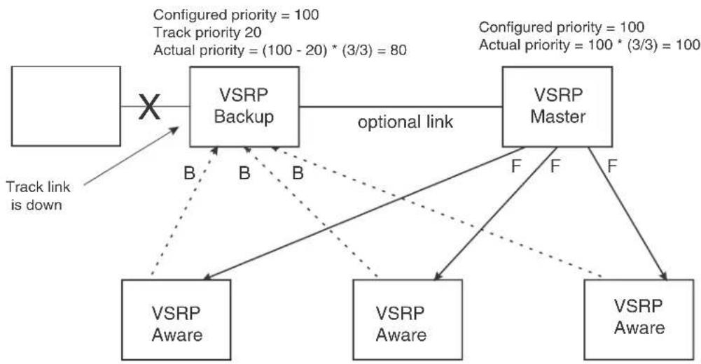
flowchart
graph TD
A["Track link is down"] --> B["VSRP Backup"]
B --> C["optional link"]
C --> D["VSRP Master"]
D --> E["VSRP Aware"]
D --> F["VSRP Aware"]
D --> G["VSRP Aware"]
B --> H["B"]
D --> I["F"]
style A fill:#f9f,stroke:#333
style B fill:#ccf,stroke:#333
style C fill:#cfc,stroke:#333
style D fill:#fcc,stroke:#333
style E fill:#cff,stroke:#333
style F fill:#ffc,stroke:#333
style G fill:#fcc,stroke:#333
note1["Configured priority = 100\nTrack priority 20\nActual priority = (100 - 20) * (3/3) = 80"] -.-> B
note2["Configured priority = 100\nActual priority = 100 * (3/3) = 100"] -.-> D
MAC address failover on VSRP-aware devices
VSRP-aware devices maintain a record of each VRID and its VLAN. When the device has received a Hello message for a VRID in a given VLAN, the device creates a record for that VRID and VLAN and includes the port number in the record. Each subsequent time the device receives a Hello message for the same VRID and VLAN, the device checks the port number:
- If the port number is the same as the port that previously received a Hello message, the VSRP-aware device assumes that the message came from the same VSRP Master that sent the previous message.
- If the port number does not match, the VSRP-aware device assumes that a VSRP failover has occurred to a new Master, and moves the MAC addresses learned on the previous port to the new port.
The VRID records age out if unused. This can occur if the VSRP-aware device becomes disconnected from the Master. The VSRP-aware device will wait for a Hello message for the period of time equal to the following.
$$ \text { VRID Age } = (\text { Dead Interval } + \text { Hold - down Interval } + (3 \times \text { Hello Interval })) / 1 0 $$
The values for these timers are determined by the VSRP device sending the Hello messages. If the Master uses the default timer values, the age time for VRID records on the VSRP-aware devices is as follows.
$$ 3 + 3 + (3 \times 1) / 1 0 = . 9 \text { seconds } (9 0 0 \text { milliseconds }) $$
In this case, if the VSRP-aware device does not receive a new Hello message for a VRID in a given VLAN, on any port, the device assumes the connection to the Master is unavailable and removes the VRID record.
Configuring basic VSRP parameters
To configure VSRP, perform the following required tasks.
- Configure a port-based VLAN containing the ports for which you want to provide VSRP service.
NOTE
If you already have a port-based VLAN but only want to use VSRP on a sub-set of the VLANs ports, you can selectively remove ports from VSRP service in the VLAN. Refer to “Adding or removing a port from the VRID’s VLAN” on page 433.
BigIron RX(config)# vlan 200
BigIron RX(config-vlan-200)# tag ethernet 1/1 to 1/8
- Configure a VRID.
BigIron RX(config-vlan-200)# vsrp vrid 1
Syntax: [no] vsrp vrid
The
- Specify that the device is a backup. Since VSRP, like VRRPE, does not have an "owner", all VSRP devices are backups. The active device for a VRID is elected based on the VRID priority, which is configurable.
BigIron RX(config-vlan-200-vrid-1)# backup
Syntax: [no] backup [priority
The backup command is required. In VSRP, all devices on which a VRID are configured are Backups. The Master is then elected based on the VSRP priority of each device. There is no "owner" device as there is in VRRP.
- Enable VSRP on the VRID.
BigIron RX(config-vlan-200-vrid-1)# enable
Syntax: [no] enable
or
Syntax: [no] activate
For information about the command's optional parameters, see the following:
- “Changing the backup priority” on page 435
- “Changing the default track priority” on page 438
Enabling Layer 3 VSRP
Layer 2 VSRP is enabled globally by default on the device; it just needs to be activated or enabled on a VRID. If you want to use Layer 3 VSRP, you must enable it by entering the following command at the CONFIG level.
BigIron RX(config)# router vsrp
Syntax: [no] router vsrp
- If you want to provide Layer 3 redundancy only, you could use VRRP or VRRP-Extended. You may use router vrrp or router vrrp-extended as long as router vsrp is not enabled.
Configuring optional VSRP parameters
The following sections describe how to configure optional VSRP parameters.
Disabling VSRP on a VRID
If you want to deactivate VSRP on a VRID, enter the following command.
BigIron RX(config-vlan-200-vrid-1)# disable
Syntax: disable
Configuring authentication
If the interfaces on which you configure the VRID use authentication, the VSRP packets on those interfaces also must use the same authentication. VSRP supports the following authentication types:
- No authentication – The interfaces do not use authentication. This is the default.
- Simple – The interfaces use a simple text-string as a password in packets sent on the interface. If the interfaces use simple password authentication, the VRID configured on the interfaces must use the same authentication type and the same password.
To configure a simple password, enter a command such as the following at the interface configuration level.
BigIron RX(config-if-e10000-1/6)# ip vsrp auth-type simple-text-auth ourpword
This command configures the simple text password "ourpword".
Syntax: [no] ip vsrp auth-type no-auth | simple-text-auth
The auth-type no-auth parameter indicates that the VRID and the interface it is configured on do not use authentication.
The auth-type simple-text-auth
Adding or removing a port from the VRID's VLAN
By default, all the ports in the VLAN on which you configure a VRID are interfaces for the VRID. You can remove a port from the VRID while allowing the port to remain in the VLAN.
Removing a port is useful in the following cases:
- There is no risk of a loop occurring, such as when the port is attached directly to an end host.
- You plan to use a port in an MRP ring.
To remove a port from a VRID, enter a command such as the following at the configuration level for the VRID.
BigIron RX(config-vlan-200-vrid-1)# no include-port ethernet 1/2
To return the port to the VRID, enter the following command.
BigIron RX(config-vlan-200-vrid-1)# include-port ethernet 1/2
Syntax: [no] include-port ethernet
The ethernet
Configuring a VRID IP address
If Layer 3 VSRP is enabled, you can specify an IP address to be backed up. When you specify an IP address, VSRP provides redundancy for that address. This is useful if you want to back up the gateway address used by hosts attached to the VSRP Backups.
VSRP does not require you to specify an IP address. If you do not specify an address, VSRP provides Layer 2 redundancy. If you do specify an address, VSRP provides Layer 2 and Layer 3 redundancy.
The Layer 3 redundancy support is the same as VRRPE support. For information, refer to Chapter 17, “Configuring VRRP and VRRPE”.
NOTE
The VRID IP address must be in the same subnet as a real IP address configured on the VSRP interface, but cannot be the same as a real IP address configured on the interface. Also, an IP address cannot be configured for a virtual routing interface.
NOTE
Failover applies to both Layer 2 and Layer 3.
To specify an IP address to back up, enter a command such as the following at the configuration level for the VRID.
BigIron RX(config-vlan-200-vrid-1)# ip-address 10.10.10.1
Syntax: [no] ip-address
VSRP fast start
VSRP fast start allows non-Brocade or non-VSRP aware devices that are connected to a Brocade device that is the VSRP Master to quickly switchover to the new Master when a VSRP failover occurs
This feature causes the port on a VSRP Master to restart when a VSRP failover occurs. When the port shuts down at the start of the restart, ports on the non-VSRP aware devices that are connected to the VSRP Master flush the MAC address they have learned for the VSRP master. After a specified time, the port on the previous VSRP Master (which now becomes the Backup) returns back online. Ports on the non-VSRP aware devices switch over to the new Master and learn its MAC address.
Configuring VSRP fast start
The VSRP fast start feature can be enabled on a VSRP-configured Brocade device, either on the VLAN to which the VRID of the VSRP-configured device belongs (globally) or on a port that belongs to the VRID.
To globally configure a VSRP-configured device to shut down its ports when a failover occurs, then restart after five seconds, enter the following command.
BigIron RX(configure)#vlan 100
BigIron RX(configure-vlan-100)#vsrp vrid 1
BigIron RX(configure-vlan-100-vrid-1)#fast-start 5
Syntax: [no] fast-ports
This command shuts down all the ports that belong to the VLAN when a failover occurs. All the ports will have the specified VRID.
To configure a single port on a VSRP-configured device to shut down when a failover occurs, then restart after a period of time, enter the following command.
BigIron RX(configure)#interface ethernet 1/1
BigIron RX(configure-if-1/1)#vsrp fast-start 5
Syntax: [no] vsrp fast-start
In both commands, the
Displaying ports that have the VSRP fast start feature enabled
The show vsrp vrid command shows the ports on which the VSRP fast start feature is enabled.
BigIron RX(config-vlan-10-vsrp-1)#sh vsrp
VLAN 10
Auth-type no authentication
VRID 1
==========
State Administrative-status Advertise-backup Preempt-mode
Link-Redundancy
Backup Enabled Disabled True Disabled
Parameter Configured Current Unit/Formula
Priority 100 100 (100-0)*(4.0/4.0)
Hello-interval 1 1 sec/10
Hold-interval 3 3 sec/10
Initial-ttl 2 2 hops
Master router 219.218.18.52 or MAC xxxx.dbda.1234 expires in 00:00:02
Member ports: ethe 19/1 to 19/2 ethe 19/4 to 19/5
Operational ports: ethe 19/1 to 19/2 ethe 19/4 to 19/5
Forwarding ports: None
fast-start ports: 19/1(10) 19/2(10) 19/4(10) 19/5(1)
Track-port 19/3 priority 50 status up
The "fast-start ports:" line lists the ports that have the VSRP fast start enabled, and the downtime for each port.
Changing the backup priority
When you enter the backup command to configure the device as a VSRP Backup for the VRID, you also can change the backup priority and the track priority:
- The backup priority is used for election of the Master. The VSRP Backup with the highest priority value for the VRID is elected as the Master for that VRID. The default priority is 100. If two or more Backups are tied with the highest priority, the Backup with the highest IP address becomes the Master for the VRID.
- The track priority is used with the track port feature. Refer to “VSRP priority calculation” on page 427 and “Changing the default track priority” on page 438.
To change the backup priority, enter a command such as the following at the configuration level for the VRID.
BigIron RX(config-vlan-200-vrid-1)# backup priority 75
Syntax: [no] backup [priority
The priority
For a description of the track-priority
Saving the timer values received from the master
The Hello messages sent by a VRID's master contain the VRID values for the following VSRP timers:
- Hello interval
-
Dead interval
-
Backup Hello interval
- Hold-down interval
Each Backup saves the configured timer values to its startup configuration file when you save the device's configuration.
NOTE
The Backups always use the value of the timer scale received from the Master, regardless of whether the timer values that are saved in the configuration are the values configured on the Backup or the values received from the Master.
VSRP slow start
In a VSRP configuration, if a Master router goes down, the Backup router with the highest priority takes over. When the Master comes back up again, it takes over from the Backup. By default, this transition from Backup back to Master takes place immediately. You can configure the VSRP slow start timer feature, which causes a specified amount of time to elapse between the time the Master is restored and when it takes over from the Backup (This range is currently set to between 1 to 600 ticks (1/10 second to 60 seconds). This interval allows time for VSRP convergence when the Master is restored.
To set the VSRP slow start timer to 3 seconds, enter the following command.
BigIron RX(config)# router vsrp
BigIron RX(config-vsrp-router)# slow-start 30
Syntax: slow-start
The ticks parameter can range from 1 to 600 ticks (1/10 second to 60 seconds).
When the VSRP slow start timer is enabled, if the Master goes down, the Backup takes over immediately. If the Master subsequently comes back up again, the amount of time specified by the VSRP slow start timer elapses (in this example, 3 seconds) before the Master takes over from the Backup.
Changing the Time-To-Live (TTL)
A VSRP Hello packet's TTL specifies how many hops the packet can traverse before being dropped. A hop can be a Layer 3 Switch or a Layer 2 Switch. You can specify from 1 – 255. The default TTL is 2. When a VSRP device (Master or Backup) sends a VSRP Hello packet, the device subtracts one from the TTL. Thus, if the TTL is 2, the device that originates the Hello packet sends it out with a TTL of 1. Each subsequent device that receives the packet also subtracts one from the packet's TTL. When the packet has a TTL of 1, the receiving device subtracts 1 and then drops the packet because the TTL is zero.
NOTE
An MRP ring is considered to be a single hop, regardless of the number of nodes in the ring.
To change the TTL for a VRID, enter a command such as the following at the configuration level for the VRID.
BigIron RX(config-vlan-200-vrid-1)# initial-ttl 5
Syntax: [no] initial-ttl
The
Changing the hello interval
The Master periodically sends Hello messages to the Backups. To change the Hello interval, enter a command such as the following at the configuration level for the VRID.
BigIron RX(config-vlan-200-vrid-1)# hello-interval 10
Syntax: [no] hello-interval
The
NOTE
The default Dead interval is three times the Hello interval plus one-half second. Generally, if you change the Hello interval, you also should change the Dead interval on the Backups.
NOTE
If you change the timer scale, the change affects the actual number of seconds.
Changing the dead interval
The Dead interval is the number of milliseconds a Backup waits for a Hello message from the Master before determining that the Master is dead. The default is 300 milliseconds. This is three times the default Hello interval.
To change the Dead interval, enter a command such as the following at the configuration level for the VRID.
BigIron RX(config-vlan-200-vrid-1)# dead-interval 30
Syntax: [no] dead-interval
The
NOTE
If you change the timer scale, the change affects the actual number of seconds.
Changing the backup hello state and interval
By default, Backups do not send Hello messages to advertise themselves to the Master. You can enable these messages if desired and also change the message interval.
To enable a Backup to send Hello messages to the Master, enter a command such as the following at the configuration level for the VRID.
BigIron RX(config-vlan-200-vrid-1)# advertise backup
Syntax: [no] advertise backup
When a Backup is enabled to send Hello messages, the Backup sends a Hello message to the Master every 6 seconds by default. You can change the interval to be up to 360 seconds.
To change the Backup Hello interval, enter a command such as the following at the configuration level for the VRID.
BigIron RX(config-vlan-200-vrid-1)# backup-hello-interval 180
Syntax: [no] backup-hello-interval
The
NOTE
If you change the timer scale, the change affects the actual number of seconds.
Changing the hold-down interval
The hold-down interval prevents Layer 2 loops from occurring during failover, by delaying the new Master from forwarding traffic long enough to ensure that the failed Master is really unavailable.
To change the Hold-down interval, enter a command such as the following at the configuration level for the VRID.
BigIron RX(config-vlan-200-vrid-1)# hold-down-interval 4
Syntax: [no] hold-down-interval
The
NOTE
If you change the timer scale, the change affects the actual number of seconds.
Changing the default track priority
When you configure a VRID to track the link state of other interfaces, if one of the tracked interface goes down, the software changes the VSRP priority of the VRID interface.
The software reduces the VRID priority by the amount of the priority of the tracked interface that went down. For example, if the VSRP interface's priority is 100 and a tracked interface with track priority 60 goes down, the software changes the VSRP interface's priority to 40. If another tracked interface goes down, the software reduces the VRID's priority again, by the amount of the tracked interface's track priority.
The default track priority for all track ports is 1. You can change the default track priority or override the default for an individual track port:
• To change the default track priority, use the backup track-priority command, described below.
- To override the default track priority for a specific track port, use the track-port command. Refer to "Specifying a track port" on page 439.
To change the track priority, enter a command such as the following at the configuration level for the VRID.
BigIron RX(config-vlan-200-vrid-1)# backup track-priority 2
Syntax: [no] backup [priority
Specifying a track port
You can configure the VRID on one interface to track the link state of another interface on the device. This capability is useful for tracking the state of the exit interface for the path for which the VRID is providing redundancy. Refer to "VSRP priority calculation" on page 427.
To configure a VRID to track an interface, enter a command such as the following at the configuration level for the VRID.
BigIron RX(config-vlan-200-vrid-1)# track-port e 2/4
Syntax: [no] track-port ethernet
The priority
NOTE
The priority
Disabling or re-enabling backup pre-emption
By default, a Backup that has a higher priority than another Backup that has become the Master can preempt the Master, and take over the role of Master. If you want to prevent this behavior, disable preemption.
Preemption applies only to Backups and takes effect only when the Master has failed and a Backup has assumed ownership of the VRID. The feature prevents a Backup with a higher priority from taking over as Master from another Backup that has a lower priority but has already become the Master of the VRID.
Preemption is especially useful for preventing flapping in situations where there are multiple Backups and a Backup with a lower priority than another Backup has assumed ownership, because the Backup with the higher priority was unavailable when ownership changed.
If you enable the non-preempt mode (thus disabling the preemption feature) on all the Backups, the Backup that becomes the Master following the disappearance of the Master continues to be the Master. The new Master is not preempted.
To disable preemption on a Backup, enter a command such as the following at the configuration level for the VRID.
BigIron RX(config-vlan-200-vrid-1)# non-preempt-mode
Syntax: [no] non-preempt-mode
Port transition hold timer
Using this VSRP command will delay the sending of port "up"/"down" events. This command affects the physical link events. However, the resulting logical link events are also delayed. This is a per-interface command.
For example, if VSRP is enabled on the port, the ownership would not change until the port status has remained up or down for the configured amount of time to ensure that minor transient states of a link do not unintentionally cause a disruptive topology change in the network.
NOTE
All trunk ports must have the same delayed-link-down-event configuration.
The following command will delay the sending of port "down" event for 100ms when a port state is detected "down". If the port state is detected "up" afterwards within 100ms, the delayed "down" event is cancelled; otherwise, the "down" event is sent after 100ms. This allows the upper layer applications not to be affected by a port state flapping.
BigIron RX (config-if-e1000-1/2)# delay-link-event 2 down
Syntax: delay-link-event
The
The
The
Clearing VSRP information
You can clear all VSRP statistics, globally and per-instance, by entering the following command.
BigIron RX# clear vsrp
Syntax: clear vsrp
VSRP and MRP signaling
A device may connect to an MRP ring through VSRP to provide a redundant path between the device and the MRP ring. VSRP and MRP signaling, ensures rapid failover by flushing MAC addresses appropriately. The host on the MRP ring learns the MAC addresses of all devices on the MRP ring and VSRP link. From these MAC addresses, the host creates a MAC database (table), which is used to establish a data path from the host to a VSRP-linked device. Figure 81 below shows two possible data paths from the host to Device 1.
FIGURE 81 Two data paths from host on an MRP ring to a VSRP-linked device
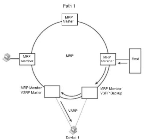
flowchart
graph TD
A["User"] --> B["MRP Member"]
B --> C["MRP Member"]
C --> D["MRP Member VSRP Backup"]
D --> E["Device 1"]
E --> F["Host"]
F --> G["MRP Master"]
G --> H["MRP Member"]
H --> I["MRP Member VSRP Master"]
I --> J["MSR"]
J --> K["MSR"]
K --> L["MSR"]
L --> M["MSR"]
M --> N["MSR"]
N --> O["MSR"]
O --> P["MSR"]
P --> Q["MSR"]
Q --> R["MSR"]
R --> S["MSR"]
S --> T["MSR"]
T --> U["MSR"]
U --> V["MSR"]
V --> W["MSR"]
W --> X["MSR"]
X --> Y["MSR"]
Y --> Z["MSR"]
Z --> A

If a VSRP failover from master to backup occurs, VSRP needs to inform MRP of the topology change; otherwise, data from the host continues along the obsolete learned path and never reach the VSRP-linked device, as shown in Figure 82.
FIGURE 82 VSRP on MRP rings that failed over
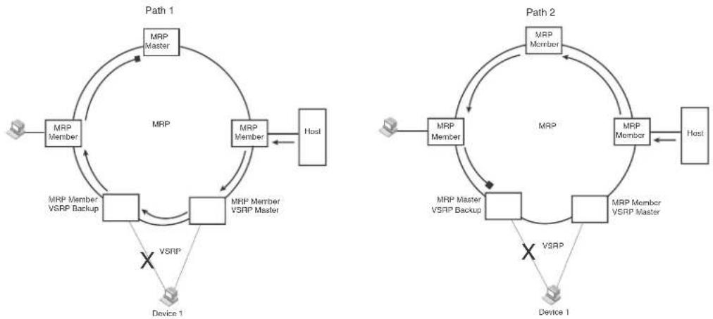
To ensure that MRP is informed of the topology change and to achieve convergence rapidly, there is a signaling process that controls the interaction between VSRP and MRP. When a VSRP node fails, a new VSRP master is selected. The new VSRP master finds all MRP instances impacted by the failover. Then each MRP instance does the following:
• The MRP node sends out an MRP PDU with the mac-flush flag set three times on the MRP ring.
- The MRP node that receives this MRP PDU empties all the MAC address entries from its interfaces that participate on the MRP ring.
- The MRP node then forwards the MRP PDU with the mac-flush flag set to the next MRP node that is in forwarding state.
The process continues until the Master MRP node's secondary (blocking) interface blocks the packet. Once the MAC address entries have been flushed, the MAC table can be rebuilt for the new path from the host to the VSRP-linked device (Figure 83).
FIGURE 83 New path established

flowchart
graph TD
A["User"] --> B["MRP Member"]
B --> C["MRP Member"]
C --> D["Host"]
D --> E["MRP Member VSRP Master"]
E --> F["MRP Member VSRP Backup"]
F --> G["VSRP"]
G --> H["Device 1"]
H --> I["Cross Symbol"]
I --> F
style A fill:#f9f,stroke:#333
style B fill:#ccf,stroke:#333
style C fill:#cfc,stroke:#333
style D fill:#fcc,stroke:#333
style E fill:#cff,stroke:#333
style F fill:#ffc,stroke:#333
style G fill:#cfc,stroke:#333
style H fill:#fcc,stroke:#333
style I fill:#ffc,stroke:#333
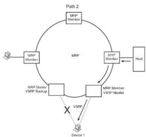
flowchart
graph TD
A["Device 1"] -->|VSRP| B["MRP Member"]
B --> C["Host"]
C --> D["MRP Member"]
D --> E["MRP Member VSRP Backup"]
E --> F["MRP Member VSRP Master"]
F --> G["Path 2"]
G --> H["MRP Member"]
H --> I["MRP Member"]
I --> J["MRP Member VSRP Backup"]
J --> K["MRP Member VSRP Master"]
K --> L["MRP Member VSRP Backup"]
L --> M["MRP Member VSRP Master"]
M --> N["MRP Member VSRP Backup"]
N --> O["MRP Member VSRP Master"]
O --> P["MRP Member VSRP Backup"]
P --> Q["MRP Member VSRP Master"]
Q --> R["MRP Member VSRP Backup"]
R --> S["MRP Member VSRP Master"]
S --> T["MRP Member VSRP Backup"]
T --> U["MRP Member VSRP Master"]
U --> V["MRP Member VSRP Backup"]
V --> W["MRP Member VSRP Master"]
W --> X["MRP Member VSRP Backup"]
X --> Y["MRP Member VSRP Master"]
Y --> Z["MRP Member VSRP Backup"]
There are no CLI commands used to configure this process.
Displaying VSRP information
You can display the following VSRP information:
- Configuration information and current parameter values for a VRID or VLAN
- The interfaces on a VSRP-aware device that are active for the VRID
Displaying VRID information
To display detailed VSRP information, enter the show vsrp vrid or show vsrp vlan command. Both commands show the same information as in the following example.
BigIron RX# show vsrp vrid 100
VLAN 10
Auth-type no authentication
VRID 10
==================
State Administrative-status Advertise-backup Preempt-mode
Master Enabled Disabled True
Parameter Configured Current Unit/Formula
Priority 100 80 (100-0)*(4.0/5.0)
Hello-interval 1 1 sec/10
Dead-interval 3 3 sec/10
Hold-interval 3 3 sec/10
Initial-ttl 2 2 hops
Backup-Hello 60 60 sec/10
Next hello sent in 00:00:01
Member ports: ethe 3/1 ethe 3/3 ethe 6/1 ethe 11/1 ethe 14/1
Operational ports: ethe 3/1 ethe 3/3 ethe 6/1 ethe 14/1
Forwarding ports: ethe 3/1 ethe 3/3 ethe 6/1 ethe 14/1
Restart ports: 3/1(10) 3/3(10) 6/1(10) 11/1(10) 14/1(10)
Syntax: show vsrp [vrid
This display shows the following information when you use the vrid
TABLE 85 CLI display of VSRP VRID or VLAN information
| This field... Displays... | |
| Total number of VSRP routers defined The total number of VRIDs configured on this device. | |
| VLAN The VLAN on which VSRP is configured. | |
| auth-type The authentication type in effect on the ports in the VSRP VLAN. | |
| VRID parameters | |
| VRID The VRID for which the following information is displayed. | |
| state This device's VSRP state for the VRID. The state can be one of the following:initialize - VSRP is not enabled on the VRID. If the state remains "initialize" after you enable VSRP on the VRID, make sure that the VRID is also configured on the other routers and that the routers can communicate with each other.NOTE: If the state is "initialize" and the mode is incomplete, make sure you have specified the IP address for the VRID.standby - This device is a Backup for the VRID.master - This device is the Master for the VRID. | |
| Administrative-status The administrative status of the VRID. The administrative status can be one of the following:disabled - The VRID is configured on the interface but VSRP or VRRPE has not been activated on the interface.enabled - VSRP has been activated on the interface. | |
| Advertise-backup | Whether the device is enabled to send VSRP Hello messages when it is a Backup. This field can have one of the following values:disabled - The device does not send Hello messages when it is a Backup.enabled - The device does send Hello messages when it is a Backup. |
| Preempt-mode | Whether the device can be pre-empted by a device with a higher VSRP priority after this device becomes the Master. This field can have one of the following values:disabled - The device cannot be pre-empted.enabled - The device can be pre-empted. |
| save-current | The source of VSRP timer values preferred when you save the configuration. This field can have one of the following values:false - The timer values configured on this device are saved.true - The timer values most recently received from the Master are saved instead of the locally configured values. |
NOTE: For the following fields:
- Configured – indicates the parameter value configured on this device.
- Current – indicates the parameter value received from the Master.
- Unit - indicates the formula used for calculating the VSRP priority and the timer scales in effect for the VSRP timers. A timer's true value is the value listed in the Configured or Current field divided by the scale value.
TABLE 85 CLI display of VSRP VRID or VLAN information (Continued)
| This field... | Displays... |
| priority The device's preferability for becoming the Master for the VRID. During negotiation, the Backup with the highest priority becomes the Master.If two or more Backups are tied with the highest priority, the Backup interface with the highest IP address becomes the Master for the VRID. | |
| hello-interval The number of units between Hello messages from the Master to the Backups for a given VRID (1 unit = 100 milliseconds). | |
| dead-interval The configured value for the dead interval. The dead interval is thenumber of units a Backup waits for a Hello message from the Master for the VRID before determining that the Master is no longer active (1 unit = 100 milliseconds).If the Master does not send a Hello message before the dead interval expires, the Backups negotiate (compare priorities) to select a new Master for the VRID.NOTE: The value is never 0, as it defaults to 3 units. | |
| hold-interval The number of units a Backup that intends to become the Master willwait before actually beginning to forward Layer 2 traffic for the VRID (1 unit = 100 milliseconds).If the Backup receives a Hello message with a higher priority than its own before the hold-down interval expires, the Backup remains in the Backup state and does not become the new Master. | |
| initial-ttl The number of hops a Hello message can traverse after leaving the device before the Hello message is dropped.NOTE: An MRP ring counts as one hop, regardless of the number of nodes in the ring. | |
| next hello sent in The amount of time until the Master's dead interval expires. If the Backup does not receive a Hello message from the Master by the time the interval expires, either the IP address listed for the Master will change to the IP address of the new Master, or this Layer 3 Switch itself will become the Master.NOTE: This field applies only when this device is a Backup. | |
| master router The IP address of the master router. | |
| Member ports The ports in the VRID. | |
| Operational ports The member ports that are currently up. | |
| Forwarding ports The member ports that are currently in the Forwarding state. Ports that are forwarding on the Master are listed. Ports on the Standby, which are in the Blocking state, are not listed. | |
| Restart ports Lists the ports on which VSRP fast start enabled. | |
Displaying a summary of VSRP information
To obtain a summary of VSRP Information, enter the show vsrp brief command. If the command is entered on a VSRP Backup, it displays the following information.
| BigIron RX# show vsrp brief | ||||||||
| VLAN | VRID | ConfPri | CurPri | P | State | PeerMacAddruir | IpAddress | VIP |
| 10 | 10 | 100 | 80 | P | Backup | xxxx.db21.11a0 | 219.33.17.160 | None |
When the command is entered on a VSRP Master, it displays the following information.
| BigIron RX# show vsrp brief | |||||||
| VLAN | VRID | ConfPri | CurPri | P | State | PeerMacAddr or IpAddress | VIP |
| 10 | 10 | 100 | 80 | P | Master | Unknown | None |
When the command is entered on a Layer 3 VSRP, it displays the following information.
| BigIron RX# show vsrp brief | ||||||
| VLAN | VRID | ConfPri | CurPri | P State | PeerMacAddr or IpAddress | VIP |
| 100 | 1 | 150 | 1 | P Initia xxxx.1414.1404 | 20.20.20.4 | 20.20.20.100 |
| 101 | 2 | 50 | 1 | P Initia xxxx.1ele.1e01 | 30.30.30.1 | 30.30.30.100 |
Syntax: show vsrp brief
This field... Displays...
| VLAN The VLAN on which VSRP is configured. |
| VRID The VRID for which the following information is displayed. |
| ConfPri The configured priority for the device's preferability for becoming the Masterfor the VRID. |
| CurPri The device's current priority for becoming the Master. |
| P Pre-empt mode status:P – pre-emption is enabled for the VLANN – pre-emption is disabled for the VLAN |
| state This device's VSRP state for the VRID. The state can be one of the following:initialize– VSRP is not enabled on the VRID. If the state remains “initialize” after you enable VSRP on the VRID, make sure that the VRID is also configured on the other routers and that the routers can communicate with each other.NOTE:If the state is “initialize” and the mode is incomplete, make sure you have specified the IP address for the VRID.standby– This device is a Backup for the VRID.master– This device is the Master for the VRID. |
Peer MAC address or IP address MAC address or IP address of the peer.
VIP Virtual IP address for the VLAN.
Displaying VSRP packet statistics for VSRP
When Layer 3 VSRP is enabled, you can enter the following command to display VSRP statistics.
BigIron RX# show vsrp statistics
Global VSRP statistics
- received packets with checksum errors = 0
- received packets with invalid version number = 0
- received packets with unknown or inactive vrid = 43
To display VSRP statistics for a specific VLAN, enter a command such as the following:
BigIron RX# show vsrp statistics vlan 100
Displaying the active interfaces for a VRID
On a VSRP-aware device, you can display VLAN and port information for the connections to the VSRP devices (Master and Backups) using the show vsrp aware command. The command shows the active interfaces for the VRID. No output is displayed if the command is entered on a VSRP master or backup.
BigIron RX# show vsrp aware
Aware port listing
VLAN ID VRID Last Port
100 1 3/2
200 2 4/1
Syntax: show vsrp aware
This display shows the following information when you use the aware parameter. For information about the display when you use the vrid
TABLE 86 CLI display of VSRP-aware information
| This field... Displays... |
| VLAN ID The VLAN that contains the VSRP-aware device's connection with the VSRP Master and Backups. |
| VRID The VRID. |
| Last Port The most recent active port connection to the VRID. This is the port connected to the current Master. If a failover occurs, the VSRP-aware device changes the port to the port connected to the new Master. The VSRP-aware device uses this port to send and receive data through the backed up node. |
Topology overview
This chapter describes the different types of topology groups and how to configure them. A topology group is a named set of VLANs that share a Layer 2 control protocol. Topology groups simplify configuration and enhance scalability of Layer 2 protocols by allowing you to run a single instance of a Layer 2 protocol on multiple VLANs. One instance of the Layer 2 protocol controls all the VLANs.
For example, if a device is deployed in a Metro network and provides forwarding for two MRP rings that each contain 128 VLANs, you can configure a topology group for each ring. If a link failure in a ring causes a topology change, the change is applied to all the VLANs in the ring's topology group. Without topology groups, you would need to configure a separate ring for each VLAN.
You can use topology groups with the following Layer 2 protocols:
Master VLAN and member VLANs
Each topology group contains a master VLAN and can contain one or more member VLANs and VLAN groups:
- Master VLAN – The master VLAN contains the configuration information for the Layer 2 protocol. For example, if you plan to use the topology group for MRP, the topology group's master VLAN contains the ring configuration information.
- Member VLANs – The member VLANs are additional VLANs that share ports with the master VLAN. The Layer 2 protocol settings for the ports in the master VLAN apply to the same ports in the member VLANs. A change to the master VLAN's Layer 2 protocol configuration or Layer 2 topology affects all the member VLANs. Member VLANs do not independently run a Layer 2 protocol.
- Member VLAN groups – A VLAN group is a named set of VLANs. The VLANs within a VLAN group have the same ports and use the same values for other VLAN parameters.
When a Layer 2 topology change occurs on a port in the master VLAN, the same change is applied to that port in all the member VLANs that contain the port. For example, if you configure a topology group whose master VLAN contains ports 1/1 and 1/2, a Layer 2 state change on port 1/1 applies to port 1/1 in all the member VLANs that contain that port. However, the state change does not affect port 1/1 in VLANs that are not members of the topology group.
Master VLANs and customer VLANs in MRP
A topology group enables you to control forwarding in multiple VLANs using a single instance of a Layer 2 protocol such as MRP. For more information on topology group and MRP, refer to “Master VLANs and customer VLANs in a topology group” on page 408.
Control ports and free ports
A port in a topology group can be a control port or a free port:
- Control port – is a port in the master VLAN and therefore controlled by the Layer 2 protocol configured in the master VLAN. The same port in all the member VLANs is controlled by the master VLAN's Layer 2 protocol. Each member VLAN must contain all of the control ports (all other ports in the member VLAN are "free ports.").
- Free port – is not controlled by the master VLAN's Layer 2 protocol. The master VLAN can contain free ports. (In this case, the Layer 2 protocol is disabled on those ports.) In addition, any ports in the member VLANs that are not also in the master VLAN are free ports.
NOTE
Since free ports are not controlled by the master port's Layer 2 protocol, they are assumed to always be in the Forwarding state when enabled.
Configuration considerations
- You can configure up to 256 topology groups. Each group can control up to 4094 VLANs. A VLAN cannot be controlled by more than one topology group.
- The topology group must contain a master VLAN and can also contain individual member VLANs, VLAN groups, or a combination of individual member VLANs and VLAN groups. Therefore, configure the master VLAN and member VLANs or member VLAN groups before you configure a topology group.
- Once you add a VLAN as a member of a topology group, all the Layer 2 protocol information on the VLAN is deleted.
- If you add a new master VLAN to a topology group that already has a master VLAN, the new master VLAN replaces the older master VLAN. All member VLANs and VLAN groups follow the Layer 2 protocol settings of the new master VLAN.
- If you remove the master VLAN (by entering no master-vlan
), the software selects the new master VLAN from member VLANs. A new candidate master-vlan will be in configured order to a member VLAN so that the first added membe VLAN will be a new candidate master VLAN. Once you saved and reloaded, a member VLAN with the newest VLAN ID will be thenew candidate master. The new master VLAN inherits the Layer 2 protocol settings of the older master VLAN. - Once you add a VLAN or VLAN group as a member of a topology group, all the Layer 2 protocol configuration information for the VLAN or group is deleted. For example, if STP is configured on a VLAN and you add the VLAN to a topology group, the STP configuration is removed from the VLAN. Once you add the VLAN to a topology group, the VLAN uses the Layer 2 protocol settings of the master VLAN.
If you remove a member VLAN or VLAN group from a topology group, you will need to reconfigure the Layer 2 protocol information in the VLAN or VLAN group.
Configuring a topology group
To configure a topology group, enter commands such as the following.
BigIron RX(config)# topology-group 2
BigIron RX(config-topo-group-2)# master-vlan 2
BigIron RX(config-topo-group-2)# member-vlan 3
BigIron RX(config-topo-group-2)# member-vlan 4
BigIron RX(config-topo-group-2)# member-vlan 5
BigIron RX(config-topo-group-2)# member-group 2
The commands configure topology group 2 and add the following to it:
• VLAN 2 as master VLAN
• VLANs 3, 4, and 5 as member VLANs
• Member VLAN group 2
Syntax: [no] topology-group
The command creates a topology group. The
Syntax: [no] master-vlan
This command adds the master VLAN to the topology group. The VLAN must already be configured. Make sure all the Layer 2 protocol settings in the VLAN are correct for your configuration before you add the VLAN to the topology group. A topology group can have only one master VLAN.
Syntax: [no] member-vlan
This command adds a member VLAN to the topology group. The VLAN must already be configured.
Syntax: [no] member-group
This command adds a VLAN group to the topology group. The
Displaying topology group information
The following sections show how to display topology group information for VLANS.
Displaying topology group information
To display topology group information, enter the following command.
BigIron RX(config)# show topology-group
Topology Group 1
====================
Master VLAN : 2
Member VLAN : 10 20 30
Member Group : None
Control Ports : ethe 2/2 ethe 3/18 ethe 4/1 to 4/2
Free Ports :
Topology Group 2
====================
Master VLAN : 3
Member VLAN : 100 200
Member Group : None
Control Ports : ethe 4/1 to 4/2
Free Ports :
VLAN 2 - ethe 2/1 ethe 3/17
VLAN 10 - ethe 2/1 ethe 3/17
VLAN 20 - ethe 2/1 ethe 3/17
VLAN 30 - ethe 2/1 ethe 3/17
Syntax: show topology-group [
This display shows the following information.
TABLE 87 CLI display of topology group information
| This field... Displays... |
| master-vlan The master VLAN for the topology group. The settings for STP, MRP,RSTP, or VSRP on the control ports in the master VLAN apply to allcontrol ports in the member VLANs within the topology group. |
| member-vlan The member VLANs in the topology group. |
| Common control ports The master VLAN ports that are configured with Layer 2 protocolinformation. The Layer 2 protocol configuration and state of these portsin the master VLAN applies to the same port numbers in all the memberVLANs. |
| L2 protocol The Layer 2 protocol configured on the control ports. The Layer 2protocol can be one of the following:MRPSTPRSTPVSRP |
| Per vlan free ports The ports that are not controlled by the Layer 2 protocol information inthe master VLAN. |
Overview of VRRP
This chapter describes how to configure the following router redundancy protocols:
- Virtual Router Redundancy Protocol (VRRP) – The standard router redundancy protocol described in RFC 3768.
- VRRP Extended (VRRPE) – A Brocade proprietary version of VRRP that overcomes limitations in the standard protocol. This protocol works only with Brocade devices.
This section presents the standard VRRP options and the options that Brocade added in its implementation of VRRP.
Standard VRRP
VRRP is an election protocol that provides redundancy to routers within a LAN. VRRP allows you to provide alternate router paths for a host without changing the IP address or MAC address by which the host knows its gateway. Consider the situation shown in Figure 84.
FIGURE 84 Router1 is Host1's default gateway but is a single point of failure

flowchart
graph TD
A["Host1 Default Gateway 192.53.5.1"] --> B["Router1 Router2"]
B --> C["Internet or enterprise Intranet e 2/4"]
B --> D["Internet or enterprise Intranet e 3/2"]
B --> E["Internet or enterprise Intranet e 1/6 192.53.5.1"]
As shown in this example, Host1 uses 192.53.5.1 on Router1 as the host's default gateway out of the subnet. If this interface goes down, Host1 is cut off from the rest of the network. Router1 is thus a single point of failure for Host1's access to other networks.
If Router1 fails, you could configure Host1 to use Router2. Configuring one host with a different default gateway might not require too much extra administration. However, consider a more realistic network with dozens or even hundreds of hosts per subnet; reconfiguring the default gateways for all the hosts is impractical. It is much simpler to configure a VRRP virtual router on Router1 and Router2 to provide a redundant path for the hosts. If VRRP is enabled as in Figure 85, Router 2 provides the default gateway out of the subnet if Router 1 fails.
FIGURE 85 Router1 and Router2 are configured as a VRRP virtual router to provide redundant network access for Host1
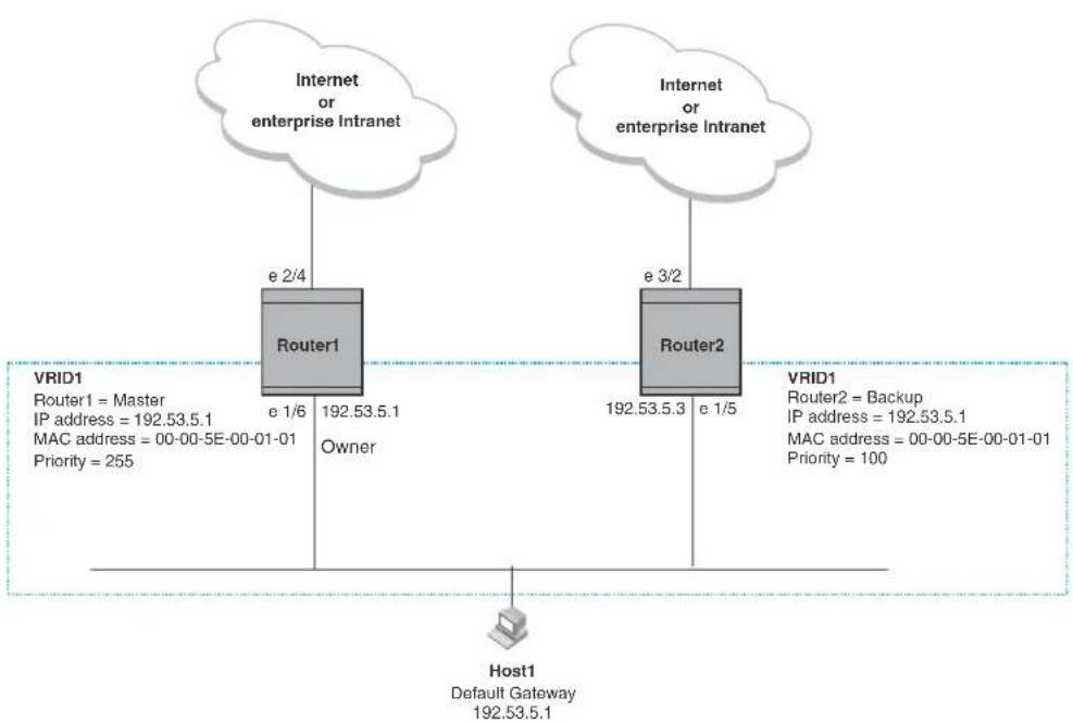
flowchart
graph TD
A["Host1\nDefault Gateway\n192.53.5.1"] --> B["Router1\ne 1/6\nOwner"]
A --> C["Router2\ne 1/5\ne 3/2\nOwner"]
B --> D["Internet or enterprise Intranet"]
C --> E["Internet or enterprise Intranet"]
style A fill:#f9f,stroke:#333
style B fill:#ccf,stroke:#333
style C fill:#ccf,stroke:#333
style D fill:#dfd,stroke:#333
style E fill:#dfd,stroke:#333
With VRRP, you configure virtual routers that span across the physical routers. A virtual router acts as a default router for hosts on a shared LAN. For example, Figure 85 has one virtual router configured identified as VRID1. This virtual router ID is associated with Router 1 and Router 2.
Since there are more than one IP addresses configured on Router 1 and Router 2, one of the physical addresses is assigned to the virtual router. For example, in Figure 85, IP address 192.53.5.1, the IP address assigned to Router 1's interface 1/6, is assigned as the IP address of virtual router VRID1. Router 1 becomes the Owner of the virtual router VRID1 and is the router that responds to packets addresses to any of the IP addresses in virtual router VRID1.
In addition, one router in the virtual router is elected as the Master router. Other routers act as backups. The Master router is the one that forwards packets sent to the IP addresses in the virtual router and answers ARP requests for these IP addresses. The Backup router takes over for the Master router when the Master router fails.
NOTE
You can provide more redundancy by also configuring a second VRID with Router2 as the Owner and Router1 as the Backup. This type of configuration is sometimes called Multigroup VRRP.
Master router election
Virtual routers use the VRRP priority values associated with each VRRP router to determine which router becomes the Master. When you configure an Owner router, the device automatically sets the its VRRP priority to 255, the highest VRRP priority. The router in the virtual router with the highest priority becomes the Master. Other routers become the backup and can be assigned priorities 3 - 254. The default priority value is 100.
Virtual routers use VRID Hello messages to determine if a Master router is available. They send Hello messages to IP Multicast address 224.0.0.18 at a specified frequency. The Backup routers waits for a duration of time for a Hello message from the Master. This duration is called the Dead Interval. If a Backup router does not receive a Hello message by the time the dead interval expires, the Backup router assumes that the Master router is dead. the Backup router with the highest priority becomes the Master router. Once the Owner router becomes available, it becomes the Master router and the current Master router returns to being a backup router.
Pre-emption
If the pre-emption feature is enabled, a Backup router that is acting as the Master can be pre-empted by another Backup router that has a higher priority. This can occur if you add a new Backup while the Owner is still available and new Backup router has a higher priority than the Backup router that is acting as Master.
Virtual router MAC address
When you configure a VRID, the software automatically assigns its MAC address as the virtual router's MAC address. The first five octets of the address are the standard MAC prefix for VRRP packets, as described in RFC 3768. The last octet is the VRID. THE VRID number becomes the final octet in the virtual router's virtual MAC address. For example, the MAC address for VRID is 000.5e00.0101.
When the virtual router becomes the Master router, it broadcasts a gratuitous ARP request containing the virtual router's MAC address for each IP address associated with the virtual router. In Figure 85, Router1 sends a gratuitous ARP with MAC address 00-00-5e-00-01-01 and IP address 192.53.5.1. Hosts use the virtual router's MAC address in routed traffic they send to their default IP gateway (in this example, 192.53.5.1).
Brocade enhancements of VRRP
Brocade enhanced VRRP by adding the following options:
- Track Ports and Track Priority
- Suppression of RIP Advertisements for Backed Up Interfaces
- Authentication
- VRRP's operation is independent of RIP, OSPF, and BGP
Track ports and track priority
Brocade enhanced VRRP by giving a VRRP router the capability to monitor the state of the interfaces on the other end of the route path through the router. For example, in Figure 85 on page 452, interface e1/6 on Router1 owns the IP address to which Host1 directs route traffic on its default gateway. The exit path for this traffic is through Router1's e2/4 interface.
Suppose interface e2/4 goes down. Even if interface e1/6 is still up, Host1 is cut off from other networks. In conventional VRRP, Router1 would continue to be the Master router despite the unavailability of the exit interface for the path the router is supporting. However, if you configure interface e1/6 to track the state of interface e2/4, if e2/4 goes down, interface e1/6 responds by changing Router1's VRRP priority to the value of the track priority. In the configuration shown in Figure 85 on page 452, Router1's priority changes from 255 to 20. One of the parameters contained in the Hello messages the Master router sends to its Backups is the Master router's priority. If the track port feature results in a change in the Master router's priority, the Backup routers quickly become aware of the change and initiate a negotiation for Master router.
In Figure 85 on page 452, the track priority results in Router1's VRRP priority becoming lower than Router2's VRRP priority. As a result, when Router2 learns that it now has a higher priority than Router1, Router2 initiates negotiation for Master router and becomes the new Master router, thus providing an open path for Host1's traffic. To take advantage of the track port feature, make sure the track priorities are always lower than the VRRP priorities. The default track priority for the router that owns the VRID IP address(es) is 2. The default track priority for Backup routers is 1. If you change the track port priorities, make sure you assign a higher track priority to the Owner of the IP address(es) than the track priority you assign on the Backup routers.
Suppression of RIP advertisements for backed up interfaces
The Brocade implementation also enhances VRRP by allowing you to configure the protocol to suppress RIP advertisements for the backed up paths from Backup routers. Normally, a VRRP Backup router includes route information for the interface it is backing up in RIP advertisements. As a result, other routers receive multiple paths for the interface and might sometimes unsuccessfully use the path to the Backup rather than the path to the Master. If you enable the Brocade implementation of VRRP to suppress the VRRP Backup routers from advertising the backed up interface in RIP, other routers learn only the path to the Master router for the backed up interface.
Authentication
For backward compatibility with RFC 2338, implementation of VRRP can use simple passwords to authenticate VRRP packets. The VRRP authentication type is not a parameter specific to the VRID. Instead, VRRP uses the authentication type associated with the interfaces on which you define the VRID. For example, if you configure your router interfaces to use a simple password to authenticate traffic, VRRP uses the same simple password and VRRP packets that do not contain the password are dropped. If your interfaces do not use authentication, neither does VRRP.
NOTE
The MD5 authentication type is not supported for VRRP.
Forcing a master router to abdicate to a standby router
You can force a VRRP Master to abdicate (give away control) of a virtual router to a Backup by temporarily changing the Master's priority to a value less than the Backup's. When you change a VRRP Owner's priority, the change takes effect only for the current power cycle. The change is not saved to the startup configuration file when you save the configuration and is not retained across a reload or reboot. Following a reload or reboot, the VRRP Owner again has priority 255.
VRRP alongside RIP, OSPF, and BGP4
VRRP operation is independent of the RIP, OSPF, and BGP4 protocols. Their operation is unaffected when VRRP is enabled on a RIP, OSPF, or BGP4 interface.
Overview of VRRPE
VRRPE is Brocade's proprietary version of VRRP that overcomes limitations in the standard protocol. It is similar to VRRP, but differs in the following respects:
- Owners and Backup:
- VRRP has an Owner and one or more Backups for each virtual router. The Owner is the router that has the IP address used for the virtual router. All the other routers supporting the virtual router are Backups.
- VRRPE does not use Owners. All routers are Backups for a given virtual router. The router with the highest priority becomes the Master. If there is a tie for highest priority, the router with the highest IP address becomes the Master. The elected Master owns the virtual IP address and answers ping and ARP requests and so on.
• Master and Backups:
- VRRP – The “Owner” of the IP address of the VRID is the default Master and has the highest priority (255). The precedence of the Backups is determined by their priorities. The default Master is always the Owner of the IP address of the VRID.
- VRRPE – The Master and Backups are selected based on their priority. You can configure any of the BigIron RX devices to be the Master by giving it the highest priority. There is no Owner.
• Virtual Router's IP address:
- VRRP requires that the virtual router has an IP address that is configured on the Owner router.
- VRRPE requires only that the virtual router's IP address be in the same subnet as an interface configured on the VRID's interface. In fact, VRRPE does not allow you to specify an IP address configured on the interface as the VRID IP address.
- VRID's MAC Address:
- VRRP source MAC is a virtual MAC address defined as 00-00-5E-00-01-
, where is the ID of the virtual router. The Master owns the Virtual MAC address. - VRRPE uses the interface's actual MAC address as the source MAC address. The virtual MAC address is 02-E0-52-
- , where is a two-octet hashed value for the IP address and is the VRID.
- Hello packets:
- VRRP sends Hello messages to IP Multicast address 224.0.0.18.
- VRRPE uses UDP to send Hello messages in IP multicast messages. The Hello packets use the interface's actual MAC address and IP address as the source addresses. The destination MAC address is 01-00-5E-00-00-02, and the destination IP address is 224.0.0.2 (the well-known IP multicast address for "all routers"). Both the source and destination UDP port number is 8888. VRRP messages are encapsulated in the data portion of the packet.
- Track ports and track priority:
- VRRP changes the priority of the VRID to the track priority, which typically is lower than the VRID priority and lower than the VRID's priorities configured on the Backups. For example, if the VRRP interface's priority is 100 and a tracked interface with track priority 20 goes down, the software changes the VRRP interface's priority to 20.
- VRRPE reduces the priority of a VRRPE interface by the amount of a tracked interface's priority if the tracked interface's link goes down. For example, if the VRRPE interface's priority is 200 and a tracked interface with track priority 20 goes down, the software changes the VRRPE interface's priority to 180. If another tracked interface goes down, the software reduces the VRID's priority again, by the amount of the tracked interface's track priority.
The most important difference is that all VRRPE routers are Backups. There is no Owner router. VRRPE overcomes the limitations in standard VRRP by removing the Owner.
Figure 86 shows an example of a VRRPE configuration.
FIGURE 86 Router1 and Router2 are configured to provide dual redundant network access for the host
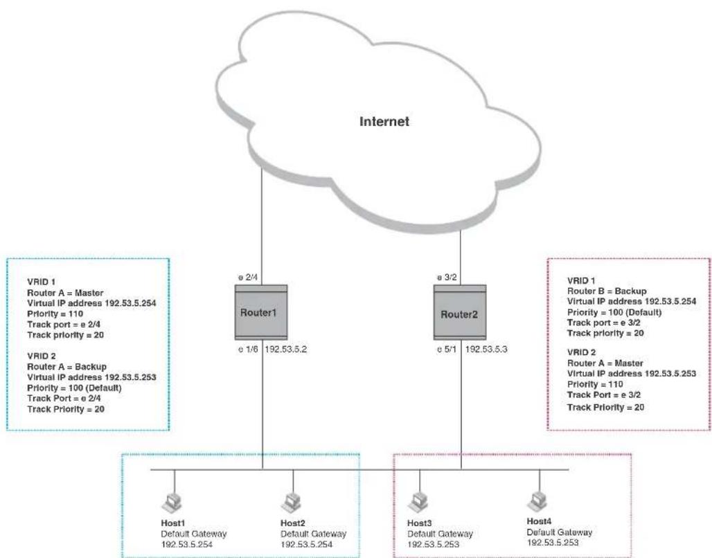
flowchart
graph TD
A["Internet"] --> B["Router1"]
A --> C["Router2"]
B --> D["Host1\nDefault Gateway\n192.53.5.254"]
B --> E["Host2\nDefault Gateway\n192.53.5.254"]
C --> F["Host3\nDefault Gateway\n192.53.5.253"]
C --> G["Host4\nDefault Gateway\n192.53.5.253"]
H["VRID 1\nRouter A = Master\nVirtual IP address 192.53.5.254\nPriority = 110\nTrack port = e 2/4\nTrack priority = 20"] --> B
I["VRID 2\nRouter A = Backup\nVirtual IP address 192.53.5.253\nPriority = 100 (Default)\nTrack Port = e 2/4\nTrack priority = 20"] --> C
J["VRID 1\nRouter B = Backup\nVirtual IP address 192.53.5.254\nPriority = 100 (Default)\nTrack port = e 3/2\nTrack priority = 20"] --> K["Host1"]
L["VRID 2\nRouter A = Master\nVirtual IP address 192.53.5.253\nPriority = 110\nTrack Port = e 3/2\nTrack priority = 20"] --> M["Host2"]
In this example, Router1 and Router2 use VRRPE to load share as well as provide redundancy to the hosts. The load sharing is accomplished by creating two VRRPE groups. Each group has its own virtual IP addresses. Half of the clients point to VRID 1's virtual IP address as their default gateway and the other half point to VRID 2's virtual IP address as their default gateway. This will enable some of the outbound Internet traffic to go through Router1 and the rest to go through Router2.
Router1 is the master for VRID 1 (backup priority = 110) and Router2 is the backup for VRID 1 (backup priority = 100). Router1 and Router2 both track the uplinks to the Internet. If an uplink failure occurs on Router1, its backup priority is decremented by 20 (track priority = 20), so that all traffic destined to the Internet is sent through Router2 instead.
Similarly, Router2 is the master for VRID 2 (backup priority = 110) and Router1 is the backup for VRID 2 (backup priority = 100). Router1 and Router2 are both tracking the uplinks to the Internet. If an uplink failure occurs on Router2, its backup priority is decremented by 20 (track priority = 20), so that all traffic destined to the internet is sent through Router1 instead.
The BigIron RX device configured for VRRPE can interoperate only with other BigIron RX devices.
VRRP and VRRPE parameters
Table 88 lists the VRRP and VRRPE parameters. Most of the parameters and default values are the same for both protocols. The exceptions are noted in the table.
TABLE 88 VRRP and VRRPE parameters
| Parameter Description Default See page... | |||
| Protocol The Virtual Router Redundancy Protocol (VRRP) based on RFC2338 or VRRP-Extended, Brocade's enhanced implementation of VRRP | DisabledNOTE: Only one of the protocols can be enabled at a time. | page 460page 462 | |
| VRRP or VRRPE router | The device's active participation as a VRRP or VRRPE router.Enabling the protocol does not activate the device for VRRP or VRRPE. You must activate the device as a VRRP or VRRPE router after you configure the VRRP or VRRPE parameters. | Inactive page 460 | page 462 |
| Virtual Router ID (VRID) | The ID of the virtual router you are creating by configuring multiple routers to back up an IP interface. You must configure the same VRID on each router that you want to use to back up the address.No default. | None page 460 | page 462 |
| Virtual Router IP address | This is the address you are backing up.No default.VRRP - The virtual router IP address must be a real IP address configured on the VRID interface on one of the VRRP routers. This router is the IP address Owner and is the default Master.VRRPE - The virtual router IP address must be in the same subnet as a real IP address configured on the VRRPE interface, but cannot be the same as a real IP address configured on the interface. | None page 460 | page 462 |
| VRID MAC address The source MAC address in VRRP or VRRPE packets sent from the VRID interface, and the destination for packets sent to the VRID.VRRP - A virtual MAC address defined as 00-00-5e-00-01-. The Master owns the Virtual MAC address.VRRPE - A virtual MAC address defined as 02-E0-52-<vrid>, where is a two-octet hashed value for the IP address and is the VRID. | Not configurable | page 453 | |
| Authentication type | The type of authentication the VRRP or VRRPE routers use to validate VRRP or VRRPE packets. The authentication type must match the authentication type the VRID's port uses with other routing protocols such as OSPF.No authentication - The interfaces do not use authentication. This is the VRRP default.Simple - The interface uses a simple text-string as a password in packets sent on the interface. If the interface uses simple password authentication, the VRID configured on the interface must use the same authentication type and the same password.NOTE: MD5 is not supported by VRRP or VRRPE. | No authentication | page 454page 463 |
| Parameter | Description | Default | See page... |
| Router type Whether the router is an Owner or a Backup.Owner (VRRP only) - The router on which the real IP address used by the VRID is configured.Backup - Routers that can provide routing services for the VRID but do not have a real IP address matching the VRID. | VRRP - The Owner is always the router that has the real IP address used by the VRID.All other routers for the VRID are Backups.VRRPE - All routers for the VRID are Backups. | page 460page 462 | |
| Backup priority A numeric value that determines a Backup's preferability for becoming the Master for the VRID. During negotiation, the router with the highest priority becomes the Master.VRRP - The Owner has the highest priority (255); other routers can have a priority from 3 - 254.VRRPE - All routers are Backups and have the same priority by default.If two or more Backups are tied with the highest priority, the Backup interface with the highest IP address becomes the Master for the VRID. | VRRP - 255 for the Owner;100 for each BackupVRRPE - 100 for all Backups | page 460page 462 | |
| Suppression of RIP advertisements | A router that is running RIP normally advertises routes to a backed up VRID even when the router is not currently the active router for the VRID. Suppression of these advertisements helps ensure that other routers do not receive invalid route paths for the VRID. | Disabled page 464 | |
| Hello interval The number of seconds between Hello messages from the Master to the Backups for a given VRID. The interval can from 1 - 84 seconds. | One second page 464 | ||
| Dead interval The number of seconds a Backup waits for a Hello message from the Master for the VRID before determining that the Master is no longer active.If the Master does not send a Hello message before the dead interval expires, the Backups negotiate (compare priorities) to select a new Master for the VRID. | Three times the Hello Interval plus one-half second | page 464 | |
| Backup Hello interval The number of seconds between Hello messages from a Backup to the Master.The message interval can be from 60 - 3600 seconds.You must enable the Backup to send the messages. The messages are disabled by default on Backups. The current Master (whether the VRRP Owner or a Backup) sends Hello messages by default. | Disabled60 seconds when enabled | page 465 | |
| Track port Another device port or virtual interface whose link status is tracked by the VRID's interface.If the link for a tracked interface goes down, the VRRP or VRRPE priority of the VRID interface is changed, causing the devices to renegotiate for Master. | None page 454 | page 465 | |
| Parameter Description Default See page... | |||
| Track priority A VRRP or VRRPE priority value assigned to the tracked ports. If a tracked port's link goes down, the VRID port's VRRP or VRRPE priority changes.VRRP – The priority changes to the value of the tracked port's priority.VRRPE – The VRID port's priority is reduced by the amount of the tracked port's priority. | VRRP – 2VRRPE – 5 | page 454page 465 | |
| Backup preempt mode | Prevents a Backup with a higher VRRP priority from taking control of the VRID from another Backup that has a lower priority but has already assumed control of the VRID. | Enabled page 466 | |
Configuring parameters specific to VRRP
VRRP is configured at the interface level. To implement a simple VRRP configuration using all the default values, enter commands such as the following.
Configuring the owner
To configure the VRRP Owner router, enter the following commands on the router that will be the Owner.
Router1(config)# router vrrp
Router1(config)# inter e 1/6
Router1(config-if-e10000-1/6)# ip address 192.53.5.1
Router1(config-if-e10000-1/6)# ip vrrp vrid 1
Router1(config-if-e10000-1/6-vrid-1)# owner
Router1(config-if-e10000-1/6-vrid-1)# ip-address 192.53.5.1
Router1(config-if-e10000-1/6-vrid-1)# activate
Syntax: router vrrp
Syntax: ip vrrp vrid
Syntax: owner [track-priority
Syntax: activate
The track-priority
Syntax: ip-address
The IP address you assign to the Owner must be an IP address configured on an interface that belongs to the virtual router.
Refer to "Configuration rules for VRRP" on page 461 for additional requirements.
Configuring basic VRRP parameters
To implement a simple VRRP configuration using all the default values, enter commands such as the following.
Configuring the owner
Router1(config)# router vrrp
Router1(config)# inter e 1/6
Router1(config-if-1/6)# ip address 192.53.5.1
Router1(config-if-1/6)# ip vrrp vrid 1
Router1(config-if-1/6-vrid-1)# owner
Router1(config-if-1/6-vrid-1)# ip-address 192.53.5.1
Router1(config-if-1/6-vrid-1)# activate
Configuring a backup
To configure the VRRP Backup router, enter the following commands.
Router2(config)# router vrrp
Router2(config)# inter e 1/5
Router2(config-if-e10000-1/5)# ip address 192.53.5.3
Router2(config-if-e10000-1/5)# ip vrrp vrid 1
Router2(config-if-e10000-1/5-vrid-1)# backup
Router2(config-if-1/5-vrid-1)# advertise backup
Router2(config-if-e10000-1/5-vrid-1)# ip-address 192.53.5.1
Router2(config-if-e10000-1/5-vrid-1)# activate
When you configure a Backup router, the router interface on which you are configuring the VRID must have a real IP address that is in the same subnet as the address associated with the VRID by the Owner. However, the address cannot be the same.
Syntax: router vrrp
Syntax: backup [priority
The priority
Enter a value of 3 - 254 for the track-priority
Syntax: ip-address
Refer to "Configuration rules for VRRP" on page 461 for additional requirements.
Configuration rules for VRRP
- The interfaces of all routers in a virtual router must be in the same IP subnet.
- The IP address(es) associated with the virtual router must already be configured on the router that will be the Owner router.
- The IP address for the virtual router must be on only one router.
- The Hello interval must be set to the same value on both the Owner and Backups for the virtual router.
- The Dead interval must be set to the same value on both the Owner and Backups for the virtual router.
- The track priority on a router must be lower than the router's VRRP priority. Also, the track priority on the Owner must be higher than the track priority on the Backups.
Configuring parameters specific to VRRPE
VRRPE is configured at the interface level. To implement a simple VRRPE configuration using all the default values, enter commands such as the following on each BigIron RX.
BigIron RX(config)# router vrrp-extended
BigIron RX(config)# inter e 1/5
BigIron RX(config-if-e10000-1/5)# ip address 192.53.5.3
BigIron RX(config-if-e10000-1/5)# ip vrrp-extended vrid 1
BigIron RX(config-if-e10000-1/5-vrid-1)# backup priority 50 track-priority 10
BigIron RX(config-if-e10000-1/5-vrid-1)# ip-address 192.53.5.254
BigIron RX(config-if-e10000-1/5-vrid-1)# activate
Syntax: ip vrrp-extended vrid
Syntax: backup [priority
Refer to "Authentication type" on page 463 for information on the auth-type no-auth | simple-text-auth
Also, refer to "Configuration rules for VRRPE" on page 462 additional information on how to configure VRRPE.
BigIron RX requires you to identify a VRRPE router as a Backup before you can activate the virtual router. However, after you configure the virtual router, you can use the backup command to change its priority or track priority.
You also can use the enable command to activate the configuration. This command does the same thing as the activate command.
Configuration rules for VRRPE
- The interfaces of all routers in a virtual router must be in the same IP subnet.
- The IP address assigned to the virtual router cannot be configured on any of the BigIron RX devices.
- The Hello interval must be set to the same value on all the BigIron RX devices.
- The Dead interval must be set to the same value on all the BigIron RX devices.
- The track priority for a virtual router must be lower than the VRRPE priority.
NOTE
If you disable VRRPE, the device removes all the configuration information for the disabled protocol from the running configuration. Moreover, when you save the configuration to the startup configuration after disabling the protocol, all configuration information for the disabled protocol is removed from the startup configuration.
Configuring additional VRRP and VRRPE parameters
You can modify the following VRRP and VRRPE parameters on each individual virtual router. These parameters apply to both protocols:
- Authentication type (if the interfaces on which you configure the virtual router use authentication)
- Backup priority
• Suppression of RIP advertisements on Backup routes for the backed up interface - Hello interval
- Dead interval
• Backup Hello messages and message timer (Backup advertisement) - Track port
- Track priority
- Backup preempt mode
• Master Router Abdication and Reinstatement
Refer to “VRRP and VRRPE parameters” on page 458 for a summary of the parameters and their defaults.
Authentication type
If the interfaces on which you configure the virtual router use authentication, the VRRP or VRRPE packets on those interfaces also must use the same authentication. Brocade's implementation of VRRP and VRRPE supports the following authentication types:
- No authentication – The interfaces do not use authentication. This is the default for VRRP and VRRPE.
- Simple – The interfaces use a simple text-string as a password in packets sent on the interface. If the interfaces use simple password authentication, the virtual router configured on the interfaces must use the same authentication type and the same password.
To configure the interface on Router1 for simple-password authentication using the password "ourpword", enter the following commands.
Configuring router 1
Router1(config)#inter e 1/6
Router1(config-if-e10000-1/6)# ip vrrp auth-type simple-text-auth ourpword
Configuring router 2
Router2(config)#inter e 1/5
Router2(config-if-e10000-1/5)# ip vrrp auth-type simple-text-auth ourpword
Syntax: ip vrrp auth-type no-auth | simple-text-auth
The auth-type no-auth parameter indicates that the virtual router and the interface it is configured on do not use authentication.
The auth-type simple-text-auth
Suppression of RIP advertisements on backup routers for the backup up interface
Normally, a VRRP or VRRPE Backup includes route information for the virtual IP address in RIP advertisements. As a result, other routers receive multiple paths for the Backup router and might sometimes unsuccessfully use the path to the Backup router rather than the path to the Master.
You can prevent the Backup routers from advertising route information for the interface on which they are defined by enabling suppression of the advertisements.
To suppress RIP advertisements for interface on which a Backup router is defined in Router2, enter the following commands.
Router2(config)# router rip
Router2(config-rip-router)# use-vrrp-path
Syntax: use-vrrp-path
The syntax is the same for VRRP and VRRPE.
Hello interval
The Master periodically sends Hello messages to the Backups. The Backups use the Hello messages as verification that the Master is still on-line. If the Backup routers stop receiving the Hello messages for the period of time specified by the Dead interval, the Backup routers determine that the Master router is dead. At this point, the Backup router with the highest priority becomes the new Master router.
The default Dead interval is three times the Hello Interval plus one-half second. Generally, if you change the Hello interval, you also should change the Dead interval on the Backup routers.
To change the Hello interval on the Master to 10 seconds, enter the following commands.
Router1(config)# inter e 1/6
Router1(config-if-e10000-1/6)# ip vrrp vrid 1
Router1(config-if-e10000-1/6-vrid-1)# hello-interval 10
Syntax: hello-interval
The Hello interval can be from 1 - 84 seconds. The default is 1 second.
The syntax is the same for VRRP and VRRPE.
Dead interval
The Dead interval is the number of seconds a Backup waits for a Hello message from the Master before determining that the Master is dead. When Backups determine that the Master is dead, the Backup with the highest priority becomes the new Master. The Dead interval can be from 1 - 84 seconds. The default is 3.5 seconds. This is three times the default Hello interval (1 second) plus one-half second added by the router software. The software automatically adds one-half second to the Dead interval value you enter.
To change the Dead interval on a Backup to 30 seconds, enter the following commands.
Router2(config)# inter e 1/5
Router2(config-if-e10000-1/5)# ip vrrp vrid 1
Router2(config-if-e10000-1/5-vrid-1)# dead-interval 30
Syntax: dead-interval
The Dead interval can be from 1 - 84 seconds. The default is 3.5 seconds.
The syntax is the same for VRRP and VRRPE.
Backup hello message state and interval
By default, Backup do not send Hello messages to advertise themselves to the Master. You can enable these messages if desired and also change the message interval.
To enable a Backup to send Hello messages to the Master, enter commands such as the following.
BigIron RX(config)# router vrrp
BigIron RX(config)# inter e 1/6
BigIron RX(config-if-e10000-1/6)# ip vrrp vrid 1
BigIron RX(config-if-e10000-1/6-vrid-1)# advertise backup
Syntax: [no] advertise backup
When you enable a Backup to send Hello messages, the Backup sends a Hello messages to the Master every 60 seconds by default. You can change the interval to be up to 3600 seconds. To do so, enter commands such as the following.
BigIron RX(config)# router vrrp
BigIron RX(config)# inter e 1/6
BigIron RX(config-if-e10000-1/6)# ip vrrp vrid 1
BigIron RX(config-if-e10000-1/6-vrid-1)# backup-hello-interval 180
Syntax: [no] backup-hello-interval
The
The syntax is the same for VRRP and VRRPE.
Track port
You can configure the virtual router to track the link state of interfaces on the device. This capability is quite useful for tracking the state of the exit interface for the path for which the virtual router is providing redundancy. Refer to “Track ports and track priority” on page 454.
To configure 1/6 on Router1 to track interface 2/4, enter the following commands.
Router1(config)# inter e 1/6
Router1(config-if-e10000-1/6)# ip vrrp vrid 1
Router1(config-if-e10000-1/6-vrid-1)# track-port e 2/4
Syntax: track-port ethernet
The syntax is the same for VRRP and VRRPE.
Track priority
If you configure a virtual router to track the link state of interfaces and one of the tracked interface goes down, the software changes the VRRP or VRRPE priority of the virtual router:
- For VRRP, the software changes the priority of the virtual router to a track priority that is lower than that of the virtual router priority and lower than the priorities configured on the Backups. For example, if the virtual router priority is 100 and a tracked interface with track priority 60 goes down, the software changes the virtual router priority to 60.
- For VRRPE, the software reduces the virtual router priority by the amount of the priority of the tracked interface that went down. For example, if the VRRPE interface's priority is 100 and a tracked interface with track priority 60 goes down, the software changes the VRRPE interface's priority to 40. If another tracked interface goes down, the software reduces the virtual router's priority again, by the amount of the tracked interface's track priority.
The default track priority for a VRRP Owner is 2. The default track priority for Backups is 1.
You enter the track priority as a parameter with the owner or backup command. Refer to “Track port” on page 465.
Syntax: owner [track-priority
Syntax: backup [priority
The syntax is the same for VRRP and VRRPE.
Backup preempt
By default, a Backup that has a higher priority than another Backup that has become the Master can preempt the Master, and take over the role of Master. If you want to prevent this behavior, disable preemption.
Preemption applies only to Backups and takes effect only when the Master has failed and a Backup has assumed ownership of the virtual router. The feature prevents a Backup with a higher priority from taking over as Master from another Backup that has a lower priority but has already become the Master of the virtual router.
Preemption is especially useful for preventing flapping in situations where there are multiple Backups and a Backup with a lower priority than another Backup has assumed ownership, because the Backup with the higher priority was unavailable when ownership changed.
If you enable the non-preempt mode (thus disabling the preemption feature) on all the Backups, the Backup that becomes the Master following the disappearance of the Master continues to be the Master. The new Master is not preempted.
NOTE
In VRRP, regardless of the setting for the preempt parameter, the Owner always returns to be the Master when it comes back online.
To disable preemption on a Backup, enter commands such as the following.
Router1(config)# inter e 1/6 Router1(config-if-e10000-1/6)# ip vrrp vrid 1 Router1(config-if-e10000-1/6-vrid-1)# non-preempt-mode
Syntax: non-preempt-mode
The syntax is the same for VRRP and VRRPE.
Master router abdication and reinstatement
To change the Master's priority, enter commands such as the following.
BigIron RX(config)# ip int eth 1/6
BigIron RX(config-if-e10000-1/6)# ip vrrp vrid 1
BigIron RX(config-if-e10000-1/6-vrid-1)# owner priority 99
Syntax: [no] owner priority | track-priority
The
When you press Enter, the software changes the priority of the Master to the specified priority. If the new priority is lower than at least one Backup's priority for the same virtual router, the Backup takes over and becomes the new Master until the next software reload or system reset.
To verify the change, enter the following command from any level of the CLI.
BigIron RX(config-if-e10000-1/6-vrid-1)# show ip vrrp
Total number of VRRP routers defined: 1
Interface ethernet 1/6
auth-type no authentication
VRID 1
state backup administrative-status enabled
mode owner
priority 99
current priority 99
hello-interval 1 sec
ip-address 192.53.5.1
backup routers 192.53.5.2
This example shows that even though this BigIron RX is the Owner of the virtual router (“mode owner”), the BigIron RX’s priority for the virtual router is only 99 and the state is now “backup” instead of “active”. In addition, the administrative status is “enabled”.
To change the Master's priority back to the default Owner priority 255, enter "no" followed by the command you entered to change the priority. For example, to change the priority of a VRRP Owner back to 255 from 99, enter the following command.
BigIron RX(config-if-e10000-1/6-vrid-1)# no owner priority 99
You cannot set the priority to 255 using the owner priority command.
Displaying VRRP and VRRPE information
You can display the following information for VRRP or VRRPE:
• Summary configuration and status information
• Detailed configuration and status information
• VRRP and VRRPE Statistics
Displaying summary information
To display summary information for a device, enter the following command at any level of the CLI.
BigIron RX(config)# show ip vrrp-extended brief Total number of VRRP-Extended routers defined: 41
| Interface | VRID | Current Priority | P | State | Master IP Address | Backup IP Address | Virtual IP Address |
| v21 | 21 | 95 | P | Backup | 172.16.51.2 | Local | 172.16.51.1 |
| v22 | 22 | 95 | P | Backup | 172.16.52.2 | Local | 172.16.52.1 |
| v23 | 23 | 95 | P | Backup | 172.16.53.2 | Local | 172.16.53.1 |
| v24 | 24 | 95 | P | Backup | 172.16.54.2 | Local | 172.16.54.1 |
| v25 | 25 | 95 | P | Backup | 172.16.55.2 | Local | 172.16.55.1 |
| v26 | 26 | 95 | P | Backup | 172.16.56.2 | Local | 172.16.56.1 |
| v27 | 27 | 95 | P | Backup | 172.16.57.2 | Local | 172.16.57.1 |
Syntax: show ip vrrp [brief | ethernet
Syntax: show ip vrrp-extended [brief | ethernet
The brief parameter displays the summary information. If you do not use this parameter, detailed information is displayed instead. Refer to “Displaying detailed information” on page 469.
The ethernet
The ve
The stat parameter displays statistics. Refer to "Displaying statistics" on page 472.
This display shows the following information.
TABLE 89 CLI display of VRRP or VRRPE summary information
| This field... Displays... | |
| Total number of VRRP (or VRRP-Extended) routers defined | The total number of virtual routers configured on this BigIron RX.NOTE: The total applies only to the protocol the BigIron RX is running.For example, if the BigIron RX is running VRRPE, the total applies only to VRRPE routers. |
| Interface The interface on which VRRP or VRRPE is configured. If VRRP or VRRPEis configured on multiple interfaces, information for each interface is listed separately. | |
| VRID The ID of the virtual router configured on this interface. If multiplevirtual routers are configured on the interface, information for each virtual router is listed in a separate row. | |
| CurPri The current VRRP or VRRPE priority of this device for the virtual router. | |
P Whether the backup preempt mode is enabled. If the backup preempt mode is enabled, this field contains a "P". If the mode is disabled, this field is blank.
TABLE 89 CLI display of VRRP or VRRPE summary information (Continued)
| This field... Displays... |
| State This device's VRRP or VRRPE state for the virtual router. The state can be one of the following:Init– The virtual router is not enabled (activated). If the state remains Init after you activate the virtual router, make sure that the virtual router is also configured on the other routers and that the routers can communicate with each other.NOTE:If the state is Init and the mode is incomplete, make sure you have specified the IP address for the virtual router.Backup– This BigIron RX is a Backup for the virtual router.Master– This BigIron RX is the Master for the virtual router. |
| Master addr The IP address of the router interface that is currently the Master for the virtual router. |
| Backup addr The IP addresses of the router interfaces that are currently Backups for the virtual router. |
| VIP The virtual IP address that is being backed up by the virtual router. |
Displaying detailed information
To display detailed information, enter the following command at any level of the CLI.
BigIron RX(config)# show ip vrrp-extended
Total number of VRRP-Extended routers defined: 41
Interface v21
auth-type no authentication
VRID 21 (index 1)
interface v21
state backup
administrative-status enabled
mode non-owner (backup)
virtual mac 02e0.520b.3515
priority 95
current priority 95
track-priority 24
hello-interval 1 sec
backup hello-interval 60 sec
advertise backup enabled
dead-interval 0 sec
current dead-interval 3.6 sec
preempt-mode true
virtual ip address 172.16.51.1
next backup hello sent in 6.5 sec
master router 172.16.51.2 expires in 3.3 sec
track-port 8/1(up) 4/1(up) 8/13(up) 16/1(up)
Syntax: show ip vrrp [brief | ethernet
Syntax: show ip vrrp-extended [brief | ethernet
The brief parameter displays summary information. Refer to “Displaying summary information” on page 467.
The ethernet
The ve
The statistic parameter displays statistics. Refer to “Displaying statistics” on page 472.
This display shows the following information.
TABLE 90 CLI display of VRRP or VRRPE detailed information
| This field... Displays... | |
| Total number of VRRP (or VRRP-Extended) routers defined | The total number of virtual routers configured on this BigIron RX.NOTE: The total applies only to the protocol the BigIron RX is running.For example, if the BigIron RX is running VRRPE, the total applies only to VRRPE routers. |
| Interface parameters | |
| Interface The interface on which VRRP or VRRPE is configured. If VRRP or VRRPEis configured on multiple interfaces, information for each interface is listed separately. | |
| auth-type The authentication type enabled on the interface. | |
| Virtual router parameters | |
| VRID The virtual router configured on this interface. If multiple virtual routersare configured on the interface, information for each virtual router is listed separately. | |
| state This BigIron RX's VRRP or VRRPE state for the virtual router. The statecan be one of the following:initialize - The virtual router is not enabled (activated). If the state remains “initialize” after you activate the virtual router, make sure that the virtual router is also configured on the other routers and that the routers can communicate with each other.NOTE: If the state is “initialize” and the mode is incomplete, make sure you have specified the IP address for the virtual router.backup - This BigIron RX is a Backup for the virtual router.master - This BigIron RX is the Master for the virtual router. | |
| administrative-status The administrative status of the virtual router. The administrative statuscan be one of the following:disabled - The virtual router is configured on the interface but VRRP or VRRPE has not been activated on the interface.enabled - VRRP or VRRPE has been activated on the interface. | |
| mode Indicates whether the BigIron RX is the Owner or a Backup for the virtualrouter.NOTE: If “incomplete” appears after the mode, configuration for this virtual router is incomplete. For example, you might not have configured the virtual IP address that is being backup up by the virtual router.This field applies only to VRRP. All BigIron RX devices configured for VRRPE are Backups. | |
| virtual MAC | The virtual IP MAC address that this virtual router is backing up. |
| This field... | Displays... |
| priority The device's preferability for becoming the Master for the virtual router.During negotiation, the router with the highest priority becomes the Master.If two or more devices are tied with the highest priority, the Backup interface with the highest IP address becomes the active router for the virtual router. | |
| current priority The current VRRP or VRRPE priority of this BigIron RX for the virtual router. The current priority can differ from the configured priority (see the row above) for the following reasons:The virtual router is still in the initialization stage and has not become a Master or Backup yet. In this case, the current priority is 0.The virtual router is configured with track ports and the link on a tracked interface has gone down. Refer to “Track ports and track priority” on page 454. | |
| track priority VRRPE priority value assigned to the tracked port. | |
| hello-interval The number of seconds between Hello messages from the Master to the Backups for a given virtual router. | |
| backup hello-interval The number of seconds between Hello messages from a Backup to the Master. | |
| advertise backup The IP addresses of Backups that have advertised themselves to this BigIron RX by sending Hello messages.NOTE: Hello messages from Backups are disabled by default. You must enable the Hello messages on the Backup for the Backup to advertise itself to the current Master. Refer to “Hello interval” on page 464. | |
| dead-interval The configured value for the dead interval. The dead interval is the number of seconds a Backup waits for a Hello message from the Master for the virtual router before determining that the Master is no longer active.If the Master does not send a Hello message before the dead interval expires, the Backups negotiate (compare priorities) to select a new Master for the virtual router.NOTE: If the value is 0, then you have not configured this parameter.NOTE: This field does not apply to VRRP Owners. | |
| current dead-interval The current value of the dead interval. This is the value actually in use by this interface for the virtual router.NOTE: This field does not apply to VRRP Owners. | |
| preempt-mode Whether the backup preempt mode is enabled.NOTE: This field does not apply to VRRP Owners. | |
| This field... Displays... | |
| backup routerexpires in | The IP addresses of Backups that have advertised themselves to this Master by sending Hello messages.Thevalue indicates how long before the Backup expires. A Backup expires if you disable the advertise backup option on the Backup or the Backup becomes unavailable. Otherwise, the Backup's next Hello message arrives before the Backup expires. The Hello message resets the expiration timer.An expired Backup does not necessarily affect the Master. However, if you have not disabled the advertise backup option on the Backup, then the expiration may indicate a problem with the Backup.NOTE: This field applies only when Hello messages are enabled on the Backups (using the advertise backup option). |
| next hello sent inHow long until the Backup sends its next Hello message. | NOTE: This field applies only when this BigIron RX is the Master and the Backup is configured to send Hello messages (the advertise backup option is enabled). |
| master routerexpires in | The IP address of the Master and the amount of time until the Master's dead interval expires. If the Backup does not receive a Hello message from the Master by the time the interval expires, either the IP address listed for the Master will change to the IP address of the new Master, or this BigIron RX itself will become the Master.NOTE: This field applies only when this BigIron RX is a Backup. |
| track port The interfaces that the virtual router's interface is tracking. If the link for a tracked interface goes down, the VRRP or VRRPE priority of the virtual router interface is changed, causing the devices to renegotiate for Master.NOTE: This field is displayed only if track interfaces are configured for this virtual router. | |
Displaying statistics
To display VRRP statistics, enter the following command.
BigIron RX#show ip vrrp-extended statistics Global VRRP-Extended statistics
- received vrrp-extended packets with checksum errors = 0
- received vrrp-extended packets with invalid version number = 0
- received vrrp-extended packets with unknown or inactive vrid = 1480
Interface v10
VRID 1
- number of transitions to backup state = 1
- number of transitions to master state = 1
- total number of vrrp-extended packets received = 0
. received backup advertisements = 0
. received packets with zero priority = 0
. received packets with invalid type = 0
. received packets with invalid authentication type = 0
. received packets with authentication type mismatch = 0
. received packets with authentication failures = 0
- received packets dropped by owner = 0
- received packets with ip ttl errors = 0
- received packets with ip address mismatch = 0
- received packets with advertisement interval mismatch = 0
- received packets with invalid length = 0
- total number of vrrp-extended packets sent = 2004
- sent backup advertisements = 0
- sent packets with zero priority = 0
- received arp packets dropped = 0
- received proxy arp packets dropped = 0
- received ip packets dropped = 0
Syntax: show ip vrrp [brief | ethernet
Syntax: show ip vrrp-extended [brief | ethernet
The brief parameter displays the summary information. If you do not use this parameter, detailed information is displayed instead.
The ethernet
The ve
The statistics parameter displays statistics.
The "received vrrp packets with checksum errors" shows the number of packets that is contained in checksum errors.
The "received vrrp packets with invalid version number" shows the number of packets with invalid versions.
The "received vrrp packets with unknown or inactive vrid" shows the number of packets that contain virtual routers that are not configured on the device or its interface
Clearing VRRP or VRRPE statistics
To clear VRRP or VRRPE statistics, enter the following command at the Privileged EXEC level or any configuration level of the CLI.
BigIron RX# clear ip vrrp-stat
Syntax: clear ip vrrp-stat
Configuration examples
The following sections contain the CLI commands options for implementing the VRRP and VRRPE configurations shown in Figure 85 on page 452 and Figure 86 on page 457.
VRRP example
To implement the VRRP configuration shown in Figure 85 on page 452, enter the following commands.
Configuring Router1
To configure VRRP Router1, enter the following commands.
Router1(config)# router vrrp
Router1(config)# inter e 1/6
Router1(config-if-e10000-1/6)# ip address 192.53.5.1
Router1(config-if-e10000-1/6)# ip vrrp vrid 1
Router1(config-if-e10000-1/6-vrid-1)# owner track-priority 20
Router1(config-if-e10000-1/6-vrid-1)# track-port ethernet 2/4
Router1(config-if-e10000-1/6-vrid-1)# ip-address 192.53.5.1
Router1(config-if-e10000-1/6-vrid-1)# activate
NOTE
When you configure the Master (Owner), the address you enter with the ip-address command must already be configured on the interface.
The ip vrrp owner command specifies that this router owns the IP address you are associating with the virtual router. Because this router owns the IP address, this router is the default Master router and its VRRP priority is thus 255.
Configuring Router2
To configure Router2 in Figure 85 on page 452 after enabling VRRP, enter the following commands.
Router2(config)# router vrrp
Router2(config)# inter e 1/5
Router2(config-if-e10000-1/5)# ip address 192.53.5.3
Router2(config-if-e10000-1/5)# ip vrrp vrid 1
Router2(config-if-e10000-1/5-vrid-1)# backup priority 100 track-priority 19
Router2(config-if-e10000-1/5-vrid-1)# track-port ethernet 3/2
Router2(config-if-e10000-1/5-vrid-1)# ip-address 192.53.5.1
Router2(config-if-e10000-1/5-vrid-1)# activate
The backup command specifies that this router is a VRRP Backup for virtual router VRID1. The IP address entered with the ip-address command is the same IP address as the one entered when configuring Router1. In this case, the IP address cannot also exist on Router2, but the interface on which you are configuring the virtual router Backup must have an IP address in the same subnet. By entering the same IP address as the one associated with this virtual router on the Owner, you are configuring the Backup to back up the address, but you are not duplicating the address.
NOTE
When you configure a Backup router, the router interface on which you are configuring the virtual router must have a real IP address that is in the same subnet as the address associated with the virtual router by the Owner. However, the address cannot be the same.
The priority parameter establishes the router's VRRP priority in relation to the other VRRP routers in this virtual router. The track-priority parameter specifies the new VRRP priority that the router receives for this virtual router if the interface goes down. Refer to “Track ports and track priority” on page 454.
The activate command activates the virtual router configuration on this interface. The interface does not provide backup service for the virtual IP address until you activate the VRRP configuration.
Syntax: router vrrp
Syntax: ip vrrp vrid
Syntax: owner [track-priority
Syntax: backup [priority
Syntax: track-port ethernet
Syntax: ip-address
Syntax: activate
VRRPE example
To implement the VRRPE configuration shown in Figure 86 on page 457, configure the VRRP Routers as shown in the following sections.
Configuring Router1
To configure VRRP Router1 in Figure 86 on page 457, enter the following commands.
Router1(config)# router vrrp-extended
Router1(config)# interface ethernet 1/6
Router1(config-if-e10000-1/6)# ip address 192.53.5.2/24
Router1(config-if-e10000-1/6)# ip vrrp-extended vrid 1
Router1(config-if-e10000-1/6-vrid-1)# backup priority 110 track-priority 20
Router1(config-if-e10000-1/6-vrid-1)# track-port ethernet 2/4
Router1(config-if-e10000-1/6-vrid-1)# ip-address 192.53.5.254
Router1(config-if-e10000-1/6-vrid-1)# activate
VRRP router 1 for this interface is activating
Router1(config-if-e10000-1/6-vrid-1)# exit
Router1(config)# interface ethernet 1/6
Router1(config-if-e10000-1/6)# ip vrrp-extended vrid 2
Router1(config-if-e10000-1/6-vrid-1)# backup priority 100 track-priority 20
Router1(config-if-e10000-1/6-vrid-1)# track-port ethernet 2/4
Router1(config-if-e10000-1/6-vrid-1)# ip-address 192.53.5.253
Router1(config-if-e10000-1/6-vrid-1)# activate
VRRP router 2 for this interface is activating
NOTE
The address you enter with the ip-address command cannot be the same as a real IP address configured on the interface.
Configuring Router2
To configure Router2, enter the following commands.
Router1(config)# router vrrp-extended
Router1(config)# interface ethernet 5/1
Router1(config-if-e10000-5/1)# ip address 192.53.5.3/24
Router1(config-if-e10000-5/1)# ip vrrp-extended vrid 1
Router1(config-if-e10000-5/1-vrid-1)# backup priority 100 track-priority 20
Router1(config-if-e10000-5/1-vrid-1)# track-port ethernet 3/2
Router1(config-if-e10000-5/1-vrid-1)# ip-address 192.53.5.254
Router1(config-if-e10000-5/1-vrid-1)# activate
Router1(config-if-e10000-5/1-vrid-1)# exit
Router1(config)# interface ethernet 5/1
Router1(config-if-e10000-5/1)# ip vrrp-extended vrid 2
Router1(config-if-e10000-5/1-vrid-1)# backup priority 110 track-priority 20
Router1(config-if-e10000-5/1-vrid-1)# track-port ethernet 2/4
Router1(config-if-e10000-5/1-vrid-1)# ip-address 192.53.5.253
Router1(config-if-e10000-5/1-vrid-1)# activate
The backup command specifies that this router is a VRRPE Backup for virtual router VRID1. The IP address entered with the ip-address command is the same IP address as the one entered when configuring Router1. In this case, the IP address cannot also exist on Router2, but the interface on which you are configuring the virtual router Backup must have an IP address in the same subnet. By entering the same IP address as the one associated with this virtual router on the Owner, you are configuring the Backup to back up the address, but you are not duplicating the address.
NOTE
When you configure a Backup router, the router interface on which you are configuring the virtual router must have a real IP address that is in the same subnet as the address associated with the virtual router by the Owner. However, the address cannot be the same.
The priority parameter establishes the router's VRRPE priority in relation to the other VRRPE routers in this virtual router. The track-priority parameter specifies the new VRRPE priority that the router receives for this virtual router if the interface goes down. Refer to “Track ports and track priority” on page 454.
The activate command activates the virtual router configuration on this interface. The interface does not provide backup service for the virtual IP address until you activate the VRRPE configuration. Alternatively, you can use the enable command. The activate and enable commands do the same thing.
Syntax: router vrrp-extended
Syntax: ip vrrp-extended vrid
Syntax: backup [priority
Syntax: track-port ethernet
Syntax: ip-address
Syntax: activate
Overview of Quality of Service (QoS)
Quality of Service (QoS) features are used to prioritize the use of bandwidth in a switch. When QoS features are enabled, traffic is classified as it arrives at the switch, and processed through on the basis of configured priorities. Traffic can be dropped, prioritized for guaranteed delivery, or subject to limited delivery options as configured by a number of different mechanisms.
Classification
Classification is the process of selecting packets on which to perform QoS, reading the QoS information and assigning them a priority. The classification process assigns a priority to packets as they enter the switch. These priorities can be determined on the basis of information contained within the packet or assigned to the packet as it arrives at the switch. Once a packet or traffic flow is classified, it is mapped to one of four forwarding priority queues.
Packets on the BigIron RX are classified in up to eight traffic classes with values between 0 and 7. Packets with higher priority classifications are given a precedence for forwarding. These classes are determined by the following criteria in ascending order:
- Configured port priority – A priority can be set for all traffic that arrives at a port. This is implemented through the interface configuration.
- VLAN priority – A priority can be set for a specified port-based VLAN in the VLAN configuration.
- Packet Source MAC address – A priority can be set for a specified MAC address by assigning a static MAC entry to a specific priority in the VLAN configuration. Note: This priority affects packets sourced by this MAC address and not packed destined for this MAC address.
- Packet priority – Depending on the Trust level set, a packet can be classified by either the 802.1p priority or DSCP value that it has when it arrives at the switch. If no trust level is set, the packet will default to a priority set by earlier criteria. By default, the trust level is set to 802.1p. In addition, you can configure a port to override the DSCP value for every packet that arrives on it to a user-configured value.
Processing of classified traffic
Given the variety of different criteria, there are multiple possibilities for traffic classification within a stream of network traffic. For this reason, the priority of packets must be resolved based on which criteria takes precedence. Precedence follows the scheme illustrated in Figure 87.
FIGURE 87 Priority resolution

flowchart
graph TD
A["802.1p Priority"] --> B["Determine Trust Level"]
C["DSCP Priority"] --> B
B --> D["Set Classification to Higher of both Inputs"]
D --> E["Port-based Classification"]
D --> F["MAC-based Classification"]
E --> G["Port-based VLAN Classification"]
F --> G
B --> H["Trust Level Set to COS (default)"]
H --> B
B --> I["No Trust Level Set"]
I --> B
B --> J["Trust Level Set to DSCP"]
As shown in the figure, the first criteria considered are port-based, MAC-based, and port-based VLAN classifications. The packet is primarily classified with the higher of these two criteria. Next, the packet is classified based on the trust level set. If there is no trust level set, the packet retains the port or MAC derived QoS classification, If a trust level is set, the packet will either take the 802.1p or DSCP priority depending on which is set as the trust level.
Once a packet is classified by one of the procedures mentioned, it is mapped to an internal forwarding queue in the BigIron RX. There are four queues designated as 0 to 3. The internal forwarding priority maps to one of these four queues as shown in Table 91 through Table 94. The mapping between the internal priority and the forwarding queue cannot be changed.
Table 91 through Table 94 show the default QoS mappings on the device, which are used if the trust level for CoS or DSCP is enabled.
TABLE 91 Default QoS mappings, columns 0 to 15
| D | S | C | P | v | a | l | u | e | 0 | 1 | 2 | 3 | 4 | 5 | 6 | 7 | 8 | 9 |
| 802.1p (COS) Value | 0 | 0 | 0 | 0 | 0 | 0 | 0 | 0 | 1 | 1 | 1 | 1 | 1 | 1 | 1 | 1 | ||
| DSCP value | 0 | 1 | 2 | 3 | 4 | 5 | 6 | 7 | 8 | 9 | 1 | 0 | 1 | 1 | 1 | 2 | ||
| Internal Forwarding Priority | 0 | 0 | 0 | 0 | 0 | 0 | 0 | 0 | 1 | 1 | 1 | 1 | 1 | 1 | 1 | 1 | ||
| Forwarding Queue | 0 | 0 | 0 | 0 | 0 | 0 | 0 | 0 | 0 | 0 | 0 | 0 | 0 | 0 | 0 | 0 | ||
1 0
2 1
TABLE 92 Default QoS mappings, columns 16 to 31
| D | S | C | P | v | a | l | u | e | 1 | 6 | 1 | 7 | 1 | 8 | 1 | 9 | 2 | 0 | 2 | 1 | 2 | 2 | 2 |
| 802.1p (COS) Value | 2 | 2 | 2 | 2 | 2 | 2 | 2 | 2 | 2 | 2 | 3 | 3 | 3 | 3 | 3 | 3 | 3 | 3 | 3 | 3 | |||
| DSCP value | 16 | 17 | 18 | 19 | 20 | 21 | 22 | 23 | 24 | 25 | 26 | 27 | 28 | 29 | 30 | 31 | |||||||
| Internal Forwarding Priority | 2 | 2 | 2 | 2 | 2 | 2 | 2 | 2 | 2 | 3 | 3 | 3 | 3 | 3 | 3 | 3 | |||||||
| Forwarding Queue | 1 | 1 | 1 | 1 | 1 | 1 | 1 | 1 | 1 | 1 | 1 | 1 | 1 | 1 | 1 | 1 | |||||||
TABLE 93 Default QoS mappings, columns 32 to 47
| D | S | C | P | v | a | l | u | e | 3 | 2 | 3 | 3 | 3 | 4 | 3 | 5 | 3 | 6 | 3 | 7 | 3 | 8 | 3 |
| 802.1p (COS) Value | 4 | 4 | 4 | 4 | 4 | 4 | 4 | 4 | 4 | 4 | 5 | 5 | 5 | 5 | 5 | 5 | 5 | 5 | 5 | 5 | |||
| DSCP value | 32 | 33 | 34 | 35 | 36 | 37 | 38 | 39 | 40 | 41 | 42 | 43 | 44 | 45 | 46 | 47 | |||||||
| Internal Forwarding Priority | 4 | 4 | 4 | 4 | 4 | 4 | 4 | 4 | 5 | 5 | 5 | 5 | 5 | 5 | 5 | 5 | |||||||
| Forwarding Queue | 2 | 2 | 2 | 2 | 2 | 2 | 2 | 2 | 2 | 2 | 2 | 2 | 2 | 2 | 2 | 2 | |||||||
TABLE 94 Default QoS mappings, columns 48 to 63
| D | S | C | P | v | a | l | u | e | 4 | 8 | 4 | 9 | 5 | 0 | 5 | 1 | 5 | 2 | 5 | 3 | 5 | 4 | 5 |
| 802.1p (COS) Value | 6 | 6 | 6 | 6 | 6 | 6 | 6 | 6 | 6 | 6 | 7 | 7 | 7 | 7 | 7 | 7 | 7 | 7 | 7 | 7 | |||
| DSCP value | 48 | 49 | 50 | 51 | 52 | 53 | 54 | 55 | 56 | 57 | 58 | 59 | 60 | 61 | 62 | 63 | |||||||
| Internal Forwarding Priority | 6 | 6 | 6 | 6 | 6 | 6 | 6 | 6 | 6 | 7 | 7 | 7 | 7 | 7 | 7 | 7 | 7 | 7 | 7 | 7 | |||
| Forwarding Queue | 3 | 3 | 3 | 3 | 3 | 3 | 3 | 3 | 3 | 3 | 3 | 3 | 3 | 3 | 3 | 3 | 3 | 3 | 3 | 3 | |||
The mapping between the internal forwarding priority and values received and forwarded can be changed as follows:
- COS to DSCP Mapping – You can change the mapping between 802.1p (COS) values from the default values shown in Table 91 through Table 94. This mapping is used for DSCP marking when trust level is COS. Refer to “Changing the CoS -> DSCP mappings” on page 483.
- DSCP to DSCP Mapping – You can alter the DSCP value of a packet that is received to a value configured on the switch. This mapping is used for DSCP marking when trust level is DSCP. Refer to “Changing the DSCP -> DSCP mappings” on page 483.
- DSCP to Internal Forwarding Priority Mapping – You can change the mapping between the DSCP value and the Internal Forwarding priority value from the default values shown in Table 91 through Table 94. This mapping is used for COS marking and determining the internal priority when the trust level is DSCP. Refer to “Changing the DSCP -> internal forwarding priority mappings” on page 484.
- COS to Internal Forwarding Priority Mapping – You can change the mapping between 802.1p (COS) values and the Internal Forwarding priority value from the default values shown in Table 91 through Table 94. This mapping is used for COS marking and determining the internal priority when the trust level is COS. “Changing the CoS -> internal forwarding priority mappings” on page 485.
Marking
Marking is the process of changing the packet's QoS information (the 802.1p and DSCP information in a packet) for the next hop. You can mark a packet's Layer 2 CoS value, its Layer 3 DSCP value, or both values. The Layer 2 CoS or DSCP value the device marks in the packet is the same value that results from mapping the packet's QoS value into a Layer 2 CoS or DSCP value.
Marking is optional and is disabled by default. When marking is disabled, the device still performs mappings for scheduling the packet, but leaves the packet's QoS values unchanged when the device forwards the packet.
Configuring DSCP classification by interface
You can configure DSCP classification on an interface to set the DSCP value of every packet that arrives on the interface to a value that you configure. After the packet's DSCP value has been set using this command, it is subject to classification, marking, and scheduling operations that are configured.
To configure the 1/1 interface to set all packets that arrive on it to a DSCP value of 23, use the following command.
BigIron RX(config)# interface ethernet 1/1 BigIron RX(config-if-e1000-1/1)# dscp 23
Syntax: [no] dscp
The
Configuring port, MAC, and VLAN-based classification
Assigning QoS priorities to traffic
By default, traffic is forwarded using the best-effort queue (qosp0). However, traffic can be classified into different priorities, based on the following:
- Incoming port (sometimes called the ingress port)
• Port-based VLAN membership - Static MAC entry
The following sections describe how to change the priority for each of the items listed above.
Although it is possible for a packet to qualify for an adjusted QoS priority based on more than one of the criteria above, the system determines the priority it will use for forwarding as described in "Processing of classified traffic" on page 477.
When you apply a QoS priority to one of the items listed above, you specify a number from 0 - 7. The priority number specifies the IEEE 802.1p equivalent to one of the four Brocade QoS queues. The numbers correspond to the queues as follows.
| Priority level QoS forwarding queue |
| 6, 7 3 |
| 4, 5 2 |
| 2, 3 1 |
| 0, 1 0 |
Changing a port's priority
To change a port's QoS priority, use one of the following methods. The priority applies to inbound traffic on the port. The default priority of each port is 0.
To change the QoS priority of port 1/1 on a device to queue 2, enter the following commands.
BigIron RX(config)# interface ethernet 1/1
BigIron RX(config-if-e1000-1/1)# priority 5
Syntax: [no] priority
The
Changing a Layer 2 port-based VLAN's priority
By default, VLANs have priority 0. To change a port-based VLAN's QoS priority, use one of the following methods. The priority applies to inbound traffic on ports in the VLAN.
To change the QoS priority of port-based VLAN 20 to queue 3, enter the following commands.
BigIron RX(config)# vlan 20
BigIron RX(config-vlan-20)# priority 7
Syntax: [no] priority
The
Assigning static MAC address entries to priority queues
By default, all MAC address entries are in the best effort queue. When you configure a static MAC entry, you can assign the entry to a higher QoS level using the following method. The priority applies to packets sourced by this MAC address.
To configure a static MAC entry and assign the entry to the premium queue on a device, enter commands such as the following.
BigIron RX(config)# vlan 9
BigIron RX(config-vlan-9)# static-mac-address 1145.1163.67FF ethernet 1/1 priority 7
Syntax: [no] static-mac-address
The
Configuring ToS-based QoS
To configure ToS-based QoS, perform the following tasks:
- Enable ToS-based QoS on an interface. Once you enable the feature on an individual interface, you can configure the trust level and marking for traffic that is received on that interface as described:
- Specify the trust level for packets received on the interface.
- Enable marking of packets received on the interface.
Enabling ToS-based QoS
To enable ToS-based QoS on an interface, enter the following command at the configuration level for the interface.
BigIron RX(config-if-e1000-1/1)# qos-tos
Syntax: [no] qos-tos
Specifying trust level
If a packet arrives on the interface with either a COS, DSCP, or COS and DSCP priority level, the trust level specifies which of these priorities you want to accept. If you disable trust level, the priority will default to a criteria other than the COS or DSCP priority.
To set the trust level for an interface to dscp, enter the following command at the configuration level for the interface.
BigIron RX(config-if-e1000-1/1)# qos-tos trust dscp
Syntax: [no] qos-tos trust cos | dscp
The cos | dscp parameter specifies the trust level.
- cos – The device uses the 802.1p (CoS) priority value in the packet's Ethernet frame header to determine the packet's internal forwarding priority. This is the default state and is in effect even Qos-ToS is enabled on a port.
- dscp – The device uses the six most-significant bits in the packet's ToS field and interprets them as a DSCP value to determine the packet's internal forwarding priority.
Enabling marking
This command enables marking of the 802.1p field or the DSCP field in the ToS byte of an IP header.
Syntax: [no] qos-tos mark cos | dscp
The cos | dscp parameter specifies the type of marking.
- cos – The device changes the outbound packet's 802.1p priority value to match the results of the device's QoS mapping from the specified trust level.
- dscp – The device changes the outbound packet's DSCP value to match the results of the device's QoS mapping from the specified trust level.
Configuring the QoS mappings
The Brocade device maps a packet's 802.1p or DSCP value to an internal forwarding priority. The default mappings are listed in Table 91 through Table 94. You can change the following mappings as described in this section:
- CoS -> DSCP
- DSCP -> DSCP
- DSCP -> internal forwarding priority
- CoS -> internal forwarding priority
The mappings are globally configurable and apply to all interfaces.
NOTE
In a configuration where you have marking enabled with the trust level set to CoS, you must enter the ip rebind-acl all command at the global CONFIG level of the CLI after making the mapping change. This applies to mappings that are configured using the qos-tos map command.
NOTE
The mappings are globally configurable and apply to all interfaces.
Changing the CoS -> DSCP mappings
The CoS -> DSCP mappings are used if the trust level is CoS and DSCP marking is enabled.
To change the CoS -> DSCP mappings, enter commands such as the following at the global CONFIG level of the CLI.
BigIron RX(config)# qos-tos map cos-dscp 0 33 25 49 17 7 55 41
BigIron RX(config)# ip rebind-acl all
This command configures the mappings displayed in the COS-DSCP map portion of the QoS information display.
BigIron RX(config-if-e10000-1/1)# show qos-tos
...portions of table omitted for simplicity...
COS-DSCP map:
COS: 0 1 2 3 4 5 6 7
dscp: 0 33 25 49 17 7 55 41
Syntax: [no] qos-tos cos-dscp
The
Changing the DSCP -> DSCP mappings
The DSCP -> DSCP mappings are used when DSCP trust level and DSCP marking are enabled. To change a DSCP -> DSCP mapping, enter a command such as the following at the global CONFIG level of the CLI.
BigIron RX(config)# qos-tos map dscp-dscp 0 to 10
This command changes the mapping of DSCP value 0 to 10.
Syntax: [no] qos-tos map dscp-dscp
You can change up to seven DSCP values in the same commend.
Changing the DSCP -> internal forwarding priority mappings
This mapping is used when the trust level is set to DSCP. In addition to determining the internal-forwarding priority of a packet, the value also determines the outbound 802.1p value if CoS marking is enabled. To change the DSCP -> internal forwarding priority mappings for all the DSCP ranges, enter commands such as the following at the global CONFIG level of the CLI.
BigIron RX(config)# qos-tos map dscp-priority 0 2 3 4 to 1
BigIron RX(config)# qos-tos map dscp-priority 8 to 5
BigIron RX(config)# qos-tos map dscp-priority 16 to 4
BigIron RX(config)# qos-tos map dscp-priority 24 to 2
BigIron RX(config)# qos-tos map dscp-priority 32 to 0
BigIron RX(config)# qos-tos map dscp-priority 40 to 7
BigIron RX(config)# qos-tos map dscp-priority 48 to 3
BigIron RX(config)# qos-tos map dscp-priority 56 to 6
These commands configure the mappings displayed in the DSCP to forwarding priority portion of the QoS information display. To read this part of the display, select the first part of the DSCP value from the d1 column and select the second part of the DSCP value from the d2 row. For example, to read the DSCP to forwarding priority mapping for DSCP value 24, select 2 from the d1 column and select 4 from the d2 row. The mappings that are changed by the command above are shown below in bold type.
BigIron RX(config-if-e10000-1/1)# show qos-tos
...portions of table omitted for simplicity...
DSCP-Priority map: (dscp = d1d2)
| d1 | 2 | 0 | 1 | 2 | 3 | 4 | 5 | 6 | 7 | 8 | 9 |
| 0 | 1 | 0 | 1 | 1 | 1 | 0 | 0 | 0 | 5 | 1 | |
| 1 | 6 | 1 | 1 | 1 | 1 | 1 | 4 | 2 | 2 | 2 | |
| 2 | 2 | 2 | 2 | 2 | 2 | 3 | 3 | 3 | 3 | 3 | |
| 3 | 3 | 3 | 0 | 4 | 4 | 4 | 4 | 4 | 4 | 4 | |
| 4 | 7 | 5 | 5 | 5 | 5 | 5 | 5 | 5 | 3 | 6 | |
| 5 | 6 | 6 | 6 | 6 | 6 | 6 | 6 | 7 | 7 | 7 | |
| 6 | 7 | 7 | 7 | 7 |
For information about the rest of this display, refer to “Displaying QoS configuration information” on page 485.
Syntax: [no] qos-tos map dscp-priority
The
The
Changing the CoS -> internal forwarding priority mappings
This mapping is used when the trust level is set to CoS. In addition to determining the internal-forwarding priority of a packet, the value also determines the outbound 802.1p value if CoS marking is enabled. To change the
CoS -> internal forwarding priority mappings for all the CoS ranges, enter commands such as the following at the global CONFIG level of the CLI.
BigIron RX(config)# qos-tos map cos-priority 7 4 3 6 5 2 1 0
These commands configure the mappings displayed in the CoS to forwarding priority portion of the QoS information display. To read this part of the display, select the first part of the CoS value from the d1 column and select the second part of the CoS value from the d2 row. For example, to read the CoS to forwarding priority mapping for CoS value 24, select 2 from the d1 column and select 4 from the d2 row. The mappings that are changed by the command above are shown below in bold type.
BigIron RX(config-if-e10000-1/1)# show qos-tos
...portions of table omitted for simplicity...
COS-Priority map:
COS: 0 1 2 3 4 5 6 7
Priority: 0 1 2 3 4 5 6 7
For information about the rest of this display, refer to “Displaying QoS configuration information” on page 485.
Syntax: [no] qos-tos map cos-priority
The
Displaying QoS configuration information
To display configuration information, enter the following command at any level of the CLI.
BigIron RX# show qos-tos Interface QoS, Marking and Trust Level:
| i/f | QoS | Mark | Trust-Level | |||||||
| 1/2 | Yes | Layer 2 CoS | ||||||||
| ve1 | No | Layer 2 CoS | ||||||||
| ve4 | No | Layer 2 CoS | ||||||||
| ve5 | No | Layer 2 CoS | ||||||||
| ve20 | No | Layer 2 CoS | ||||||||
| COS-DSCP map: | ||||||||||
| COS: | 0 | 1 | 2 | 3 | 4 | 5 | 6 | 7 | ||
| dscp: | 0 | 8 | 16 | 24 | 32 | 40 | 48 | 56 | ||
| DSCP-Priority map: (dscp = dld2) | ||||||||||
| d2 | 0 | 1 | 2 | 3 | 4 | 5 | 6 | 7 | 8 | 9 |
| d1 | ||||||||||
| 0 | 0 | 0 | 0 | 0 | 0 | 0 | 0 | 0 | 1 | 1 |
| 1 | 1 | 1 | 1 | 1 | 1 | 1 | 2 | 2 | 2 | 2 |
| 2 | 2 | 2 | 2 | 2 | 3 | 3 | 3 | 3 | 3 | 3 |
| 3 | 3 | 3 | 4 | 4 | 4 | 4 | 4 | 4 | 4 | 4 |
| 4 | 5 | 5 | 5 | 5 | 5 | 5 | 5 | 5 | 6 | 6 |
| 5 | 6 | 6 | 6 | 6 | 6 | 6 | 7 | 7 | 7 | 7 |
| 6 | 7 | 7 | 7 | 7 | ||||||
| DSCP-DSCP map: (dscp = dld2) | ||||||||||
| d2 | 0 | 1 | 2 | 3 | 4 | 5 | 6 | 7 | 8 | 9 |
| d1 | ||||||||||
| 0 | 0 | 1 | 2 | 3 | 4 | 5 | 6 | 7 | 8 | 9 |
| 1 | 10 | 11 | 12 | 13 | 14 | 15 | 16 | 17 | 18 | 19 |
| 2 | 20 | 21 | 22 | 23 | 24 | 25 | 26 | 27 | 28 | 29 |
| 3 | 30 | 31 | 32 | 33 | 34 | 35 | 36 | 37 | 38 | 39 |
| 4 | 40 | 41 | 42 | 43 | 44 | 45 | 46 | 47 | 48 | 49 |
| 5 | 50 | 51 | 52 | 53 | 54 | 55 | 56 | 57 | 58 | 59 |
| 6 | 60 | 61 | 62 | 63 | ||||||
| COS-Priority map: | ||||||||||
| COS: | 0 | 1 | 2 | 3 | 4 | 5 | 6 | 7 | ||
| Priority: | 0 | 1 | 2 | 3 | 4 | 5 | 6 | 7 | ||
Syntax: show qos-tos
This command shows the following information.
TABLE 95 ToS-based QoS configuration information
| This field... Displays... |
| Interface QoS, marking and trust level information |
| i/f The interface |
QoS The state of ToS-based QoS on the interface. The state can be one of the following:
- No - Disabled
- Yes - Enabled
TABLE 95 ToS-based QoS configuration information (Continued)
| This field... Displays... | |
| Mark The marking type enabled on the interface. The marking type can be any of the following:·COS - CoS marking is enabled.·DSCP - DSCP marking is enabled.No - Marking is not enabled. | |
| Trust-Level The trust level enabled on the interface. The trust level can be one of the following:·DSCP·L2 CoS | |
| CoS-DSCP map | |
| COS The CoS (802.1p) values. | |
| dscp The DSCP values to which the device maps the CoS values above. | |
| DSCP-priority map | |
| d1 and d2 The DSCP -> forwarding priority mappings that are currently in effect. | |
| DSCP-DSCP map | |
| d1 and d2 The DSCP -> DSCP mappings that are currently in effect. | |
| CoS-priority map | The CoS (802.1p) forwarding priority mapping that is currently in effect. |
Determining packet drop priority using WRED
You can configure a device to monitor traffic congestion and drop packets according to a WRED (Weighted Random Early Detection) algorithm. This algorithm enables the system to detect the onset of congestion and take corrective action. In practice, WRED causes a Switch to start dropping packets as traffic in the switch starts to back up. WRED provides various control points that can be configured to change a system's reaction to congestion. The following variables are used when calculating whether to drop or forward packets:
- Statistical Average-Q-Size – The statistical average size of the queue calculated over time on the switch.
- Current-Q-Size – The current size of the queue as calculated on the switch.
- Wq – This variable specifies the weights that should be given to the current queue size and the statistical average-q-size when calculating the size for WRED calculations.
- Max-Instantaneous-Q-Size – The maximum size up to which a queue is allowed to grow. Packets that cause the queue to grow beyond this point are unconditionally dropped. This variable is user configured.
- Min-Average-Q-Size – The average queue size below which all packets are accepted. This variable is user configured.
- Max-Average-Q-Size – The average queue size above which all packets are dropped. This variable is user configured.
- Pmax – The maximum drop probability when queue-size is at Max-Average-Q-Size. This variable is user configured.
- Pkt-Size-Max – The packet size to which the current packet's size is compared as shown in the algorithm below. This variable is user configured.
How WRED Operates
The graph in Figure 88 describes the interaction of the previously described variables in the operation of WRED. When a packet arrives at a switch, the average queue size (q-size) is calculated (note that this is not the statistical average queue size - (refer to "Calculating avg-q-size" on page 488). If q-size as calculated is below the configured Min. Average Queue Size, then the packet is accepted. If the average queue size is above the configured Max. Average Queue Size threshold, the packet is dropped. If the Average Queue size falls between the Min. Average Queue Size and the Max. Average Queue Size, packets are dropped according to the calculated probability described in "Calculating packets that are dropped" on page 488.
FIGURE 88 WRED operation graph

line
| Queue Size Category | Pmax | | ------------------------- | ---- | | Min. Average Queue Size | 0 | | Max. Average Queue Size | 1 |Calculating avg-q-size
The algorithm first calculates the avg-q-size through the following equation.
avg-q-size = ((1 - Wq) * Statistical Average-Q-Size) + (Wq * Current-Q-Size)
The Wq value is instrumental to the calculation and can be:
• equal to the statistical average queue size (Wq == 0), or
• equal to the current queue size (Wq == 1) or
• be between 0 and 1 (0 < Wq < 1).
Lower Wq values cause the avg-q-size to lean towards the statistical average queue size, reducing WRED's sensitivity to the current state of the queue and thus reduce WRED's effectiveness. On the other hand, higher Wq values cause the avg-q-size to lean towards the instantaneous queue size, which exposes WRED to any change in the instantaneous queue size and thus may cause WRED to overreact in cases of bursts. Thus, the value of Wq should be carefully chosen according to the application at hand.
Calculating packets that are dropped
The Pdrop value, as calculated in the following equation, is the probability that a packet will be dropped in a congested switch.
$$ \text { Pdrop } = \frac {\text { pkt - size (avg - q - size - min - avg - q size) }}{\text { pkt - size - max (max - avg - q - size - min - avg - q size) }} $$
Using WRED with rate limiting
When rate limiting is configured on a device, it directs the switch to drop traffic indiscriminately when the configured average-rate and maximum-burst thresholds are exceeded. If rate limiting is configured with WRED, the traffic that exceeds these thresholds can be subjected to the WRED algorithm which drops packets selectively by priority.
In this configuration, packets that exceed the thresholds established by the rate limiting configuration are marked as either exceeding the average-rate or maximum-burst threshold. This marking is then used to select a WRED configuration that determines which packets to drop.
Configuring packet drop priority using WRED
For a description of WRED, refer to “Determining packet drop priority using WRED” on page 487. This section describes how to configure the parameters described in that section to enable the use of WRED on a device.
To configure WRED, you must configure the following parameters:
- "Enabling WRED"
- "Setting the averaging-weight (Wq) parameter"
- "Configuring the drop precedence parameters"
Enabling WRED
WRED must be enabled on any forwarding queue that you want it to operate on. To enable WRED for the forwarding queue 3, enter the following command.
BigIron RX(config)#qos queue-type 3 wired enable
Syntax: [no] qos queue-type
The
Setting the averaging-weight (Wq) parameter
The Wq parameter is configured as the averaging-weight parameter. In this implementation, you can set one of 13 (1 - 13) possible values. These values represent a Wq value as described in Table 96
TABLE 96 Possible Wq values
| Averaging weight setting | Wq value as a percentage |
| 1 50% | |
| 2 25% |
TABLE 96 Possible Wq values (Continued)
| Averaging weight setting | Wq value as a percentage | |
| 3 12.5% | ||
| 4 | 6 | 2 |
| 5 3.12% | ||
| 6 1.56% | ||
| 7 0.78% | ||
| 8 | 0 | 4 |
| 9 | 0 | 2 |
| 10 0.09% | ||
| 11 0.05% | ||
| 12 0.02% | ||
| 13 0.01% |
To set the wq parameter for queues with a queue type of 1 to 25%, use the following command.
BigIron RX(config)#qos queue-type 1 wred averaging-weight 25%
This gives the current queue size a weight of 25% over the statistical average queue size.
Syntax: [no] qos queue-type
The
The
Configuring the drop precedence parameters
The DSCP/TOS bits in packets are used to prioritize packet delivery for specified queue types. These values are from 0 to 3. Packets with a DSCP/TOS value of 0 are least likely to be dropped and packets with a DSCP/TOS of 3 are most likely to be dropped.
In addition, the maximum drop probability, the minimum and maximum average queue size, and the maximum packet size can be configured to apply selectively to packets with a specified queue type and DSCP/TOS value. The following sections describe how to set the following drop precedence parameters for each of the four DSCP/TOS values for each of the four queue types:
- "Setting the maximum drop probability"
- "Setting the minimum and maximum average queue size"
- "Setting the maximum packet size"
- Packets that do not have the DSCP/TOS value set are assigned a drop precedence equal to the DSCP/TOS level of 0.
Setting the maximum drop probability
To set the maximum drop probability when the queue size reaches the Max-average-q-size value to 20% use the following command.
BigIron RX(config)#qos queue-type 1 wred drop-precedence 0 drop-probability-max 20%
Syntax: [no] qos queue-type
The
The
The
Configuring the maximum instantaneous queue size
You can set the maximum size to which a queue is allowed to grow. Packets that cause the queue to grow beyond this setting are unconditionally dropped. To set the maximum instantaneous queue size for queues with a queue type of 1 to 32000, use the following command.
BigIron RX(config)#qos queue-type 1 max-queue-size 32
Syntax: [no] qos queue-type
The
The
Setting the minimum and maximum average queue size
To set the maximum average queue size for queue type 1 and drop precedence 0 to the maximum size of 32768 Kbytes, use the following command.
BigIron RX(config)#qos queue-type 1 wred drop-precedence 0 max-avg-queue-size 32768
Syntax: [no] qos queue-type
To set the minimum average queue size to the maximum size of 16 Kbytes, use the following command.
BigIron RX(config)#qos queue-type 1 wred drop-precedence 0 min-avg-queue-size 16
Syntax: [no] qos queue-type
The
The
The
The
Setting the maximum packet size
To set the maximum drop probability for queue type 1 and drop precedence 0 when the queue size reaches the Max-average-q-size value to 20% use the following command.
BigIron RX(config)#qos queue-type 1 wred drop-precedence 0 drop-probability-max 20%
Syntax: [no] qos queue-type
The
The
The
Restoring to default WRED parameters
Table 97 describes all of the default values for each of the WRED parameters. If you change any of the values from the default values, you can restore the defaults per queue type. To reset the queue type 1 with default values for the WRED parameters, use the following command.
BigIron RX(config)#qos queue-type 1 wred default-params
Syntax: [no] qos queue-type
The
TABLE 97 WRED default settings
| Queue type | Drop precedence | Minimum average queue size (KByte) | Maximum average queue size (KByte) | Maximum packet size (Byte) | Maximum drop probability | Maximum instantaneous queue size | Average weight |
| 0 0 356 | 1024 16384 2% | 1024 0.2% | |||||
| 1 304 1024 | 16384 4% | ||||||
| 2 256 | 1024 16384 9% | ||||||
| 3 204 | 1024 16384 10% | ||||||
| 1 | 0 | 356 | 1024 16384 2% | 1024 0.2% | |||
| 1 304 | 1024 16384 4% | ||||||
| 2 256 | 1024 16384 9% | ||||||
| 3 204 | 1024 16384 10% | ||||||
| 2 0 408 | 1024 16384 2% | 1024 0.2% | |||||
| 1 356 | 1024 16384 4% | ||||||
| 2 304 | 1024 16384 9% | ||||||
| 3 256 | 1024 16384 9% | ||||||
| 3 0 408 | 1024 16384 2% | 1024 0.2% | |||||
| 1 356 | 1024 16384 4% | ||||||
| 2 304 | 1024 16384 9% | ||||||
| 3 255 | 1024 16384 9% |
Displaying the WRED configuration
To view a WRED configuration, use the following command.
| BigIron RX#show qos wred | ||||||||
| QType | Enable | AverWt | MaxQSz | DropPrec | MinAvgQSz | MaxAvgQSz | MaxDropProb | MaxPktSz |
| 0 | Yes | 100% | 32768 | 0 | 16000 | 32000 | 30% | 512 |
| 1 | 32768 | 32768 | 0% | 512 | ||||
| 2 | 32768 | 32768 | 100% | 512 | ||||
| 3 | 32768 | 32768 | 0% | 512 | ||||
| 1 | Yes | 100% | 32768 | 0 | 32768 | 32768 | 0% | 512 |
| 1 | 32768 | 32768 | 0% | 512 | ||||
| 2 | 24000 | 24000 | 50% | 512 | ||||
| 3 | 32768 | 32768 | 0% | 512 | ||||
| 2 | No | |||||||
| 3 | No | |||||||
Syntax: show qos wred
Scheduling traffic for forwarding
If the traffic being processed by a device is within the capacity of the switch, all traffic is forwarded as received. Once we reach the point where the switch is bandwidth constrained, it becomes subject to drop priority if configured as described in "Determining packet drop priority using WRED" on page 487 or traffic scheduling as described in this section.
Traffic scheduling allows you to selectively forward traffic according to the forwarding queue that is mapped to according to one of the following schemes:
- Strict priority-based scheduling – This scheme guarantees that higher-priority traffic is always serviced before lower priority traffic. The disadvantage of strict priority-based scheduling is that lower-priority traffic can be starved of any access.
- Enhanced strict scheduling – With enhanced strict scheduling enabled, a configurable minimum bandwidth is allocated to lower-priority traffic so that it is not starved. The remaining bandwidth is used in a strict scheduling manner.
- WFQ destination-based scheduling – With WFQ destination-based scheduling enabled, some weight-based bandwidth is allocated to all queues. With this scheme, the configured weight distribution is guaranteed across all traffic leaving an egress port.
- WFQ source-based scheduling – With WFQ source-based scheduling enabled, some weight-based bandwidth is allocated to all queues. With this scheme, the configured weight distribution from an input port is guaranteed allocation in relationship to the configured weight distribution. However, because multiple input ports can aggregate traffic to a single output port, the traffic egressing a single port may not equal the configured values.
- Maximum rate-based scheduling – With maximum rate-based scheduling enabled, a configured maximum bandwidth is allocated to each priority level. Bandwidth remaining after the aggregate maximum is allocated is not used.
- Minimum rate-based scheduling – With minimum rate-based scheduling enabled, a configured minimum bandwidth is allocated to each priority level. Bandwidth remaining after the aggregate minimum is allocated is redistributed equally among the four priority queues.
Configuring traffic scheduling
Traffic scheduling is configured on a per-port basis. The following sections describe how to configure each of the traffic scheduling schemes:
- “Configuring strict priority-based traffic scheduling”
- "Configuring enhanced strict priority-based traffic scheduling"
- "Calculating the values for WFQ source and destination-based traffic scheduling"
- "Configuring WFQ destination-based traffic scheduling"
- "Configuring WFQ source-based traffic scheduling"
- "Configuring maximum rate-based traffic scheduling"
- “Configuring minimum rate-based traffic scheduling”
NOTE
Brocade only support "strict" and "destination-weighted" scheduling schemes. (qos scheduler ..) on the 16 x 10G modules.
Configuring strict priority-based traffic scheduling
To configure strict priority-based scheduling use a command such as the following.
BigIron RX(config)# interface ethernet 1/1 BigIron RX(config-if-e1000-1/1)# qos scheduler strict
Syntax: qos scheduler strict
Configuring enhanced strict priority-based traffic scheduling
To configure enhanced strict priority-based scheduling use a command such as the following.
BigIron RX(config)# interface ethernet 1/1 BigIron RX(config-if-e1000-1/1)# qos scheduler enhanced-strict 100 100 100
Syntax: qos scheduler enhanced-strict
The
The
The
Calculating the values for WFQ source and destination-based traffic scheduling
Weighted Fair Queueing (WFQ) scheduling is configured to be a percentage of available bandwidth using the following formula.
$$ \text { Weight of } q (x) = \frac {q (x)}{q 0 + q 1 + q 2 + q 3} $$
Where:
q(x) = The value of the queue that you want to determine the weight for. It can be the value of any queue (0 - 3).
q0 - q3 = the assigned values of the four queues.
Weight of q (x) = the calculated weight as a percentage of the port's total bandwidth.
For example if you assign the following values to queues 0 to 3.
- Queue 0 = 5, Queue 1 = 10, Queue 2 = 15, and Queue 3 = 20
NOTE
Where rates are configured, the minimum rate supported is 248 Kbps for 1 Gbps ports and 2480 Kbps for 10 Gbps ports.
To determine the weight of q3.
$$ \text { Weight of } q 3 = \frac {2 0}{5 + 1 0 + 1 5 + 2 0} $$
The weight of q3 is 40%. Consequently, q3 will get 40% of the port's total bandwidth.
The values of the remaining queues are calculated to be the following.
$$ \mathrm{q} 2 = 30 \%, \mathrm{q} 1 = 20 \%, \text { and } \mathrm{q} 0 = 10 \% $$
Configuring WFQ destination-based traffic scheduling
To configure WFQ destination-based scheduling use a command such as the following.
BigIron RX(config)# interface ethernet 1/1
BigIron RX(config-if-e1000-1/1)# qos scheduler destination-weighted 5 10 15 20
Syntax: qos scheduler destination-weighted
The
The
The
The
Refer to “Calculating the values for WFQ source and destination-based traffic scheduling” for information on assigning queue0-weight to queue3-weight values.
Configuring WFQ source-based traffic scheduling
To configure WFQ source-based scheduling use a command such as the following.
BigIron RX(config)# interface ethernet 1/1
BigIron RX(config-if-e1000-1/1)# qos scheduler source-weighted 25 25 25 25
Syntax: qos scheduler source-weighted
The
The
The
The
Refer to “Calculating the values for WFQ source and destination-based traffic scheduling” for information on assigning queue0-weight to queue3-weight values.
Configuring maximum rate-based traffic scheduling
To configure maximum rate-based scheduling use a command such as the following.
BigIron RX(config)# interface ethernet 1/1
BigIron RX(config-if-e1000-1/1)# qos max-rate 100 100 100 100
Syntax: qos scheduler max-rate
The
The
The
The
Configuring minimum rate-based traffic scheduling
To configure minimum rate-based scheduling use a command such as the following.
BigIron RX(config)# interface ethernet 1/1 BigIron RX(config-if-e1000-1/1)# qos min-rate 100 100 100 100
Syntax: qos scheduler min-rate
The
The
The
The
Displaying the scheduler configuration
To view a Scheduler configuration, use the following command.
| BigIron RX#show qos scheduler | ||||||
| Port | Scheduler (Rates where specified are in Kbps) | Type | Prio0 | Priol | Prio2 | Prio3 |
| 13/1 | strict | |||||
| 13/2 | enhanced-strict | Rate | 100000 | 200000 | 300000 | Remaining |
| 13/3 | min-rate | Rate | 102400 | 204800 | 307200 | 409600 |
| 13/4 | strict | |||||
| 13/5 | strict | |||||
| 13/6 | max-rate | Rate | 400000 | 400000 | 800000 | 10000000 |
| 13/7 | destination-weighted | Weight | 15 | 25 | 25 | 35 |
| 13/8 | strict | |||||
| 13/9 | source-weighted | Weight | 5 | 15 | 35 | 45 |
| 13/10 | strict | |||||
| 13/11 | strict | |||||
| 13/12 | strict | |||||
| 13/13 | strict | |||||
| 13/14 | strict | |||||
| 13/15 | strict | |||||
| 13/16 | strict | |||||
| 13/17 | strict | |||||
| 13/18 | strict | |||||
| 13/19 | strict | |||||
| 13/20 | strict | |||||
| 13/21 | strict | |||||
| 13/22 | strict | |||||
| 13/23 | strict | |||||
| 13/24 | strict | |||||
Syntax: show qos scheduler
Configuring multicast traffic engineering
Using the multicast traffic engineering feature, you can limit the amount of multicast traffic that passes through a packet processor. This command is configured on an individual port but applies to all ports connected to the same packet processor.
NOTE
If a user configures any one port between 1-12 (or 13 - 24) with a 'qos multicast best-effort rate of 1Mbps', no more then 1Mbps of multicast traffic will be forwarded at one time on ports 1-12 or (13-24).
Starting release 02.5.00, data-plane multicast traffic is rate-limited to 1.8 Gbps per packet processor.
NOTE
Using the qos multicast best-effort rate command affects data-plane (non-control protocol) multicast, broadcast and unknown unicast flooded traffic, that prior to inclusion of the command there was a potential for this traffic to starve other traffic from accessing an egress queue. The limiting on a per traffic manager basis to 1.8 Gbps was best for the majority of environments. Some high intensity multicast environments may need to increase this value to better match their network requirements.
To limit the multicast traffic through the packet processor that includes port 1/1 to 10 Mbps, use the following command.
BigIron RX(config)# interface ethernet 1/1
BigIron RX(config-if-e1000-1/1)# qos multicast best-effort rate 10000
Syntax: qos multicast best-effort rate
The
This variable is configured in Kbps.
The minimum configurable rate is 10 Mbps.
Displaying the multicast traffic engineering configuration
To view multicast traffic engineering configurations, use the following command.
| BigIron RX#show qos multicast | |
| Port | Best EffortBandwidth (Kbps) |
| 13/1 | 140000 |
| 13/2 | 140000 |
| 13/3 | 140000 |
| 13/4 | 140000 |
| 13/5 | 140000 |
| 13/6 | 140000 |
| 13/7 | 140000 |
| 13/8 | 140000 |
| 13/9 | 140000 |
| 13/10 | 140000 |
| 13/11 | 140000 |
| 13/12 | 140000 |
| 13/13 | 12000000 |
| 13/14 | 12000000 |
| 13/15 | 12000000 |
| 13/16 | 12000000 |
| 13/17 | 12000000 |
| 13/18 | 12000000 |
| 13/19 | 12000000 |
| 13/20 | 12000000 |
| 13/21 | 12000000 |
| 13/22 | 12000000 |
| 13/23 | 12000000 |
| 13/24 | 12000000 |
Syntax: show qos multicast [
The
- 16-port 10 Gigabit EtherneBigIron RXThe 16-port 10 Gigabit Ethernet module works in Server mode by default.Mirror (analyzer) ports cannot be assigned to the 16x10GE card. You can monitor traffic on 16x10 ports.
- Brocade currently only support "strict" and "destination-weighted" scheduling schemes.
• Virtual interface subsets are not supported for engress ACLs.
- The egress filtering of the 16x10 module only compares to 3 bits of TOS field (delay, throughput, reliability).
• The 16 x10 GE module consists of 4 port groups of 4 ports each: Port group 1: ports 1,5,9,13
• Port group 2: ports 2,6,10,14
• Port group 3: ports 3,7,11,15
• Port group 4: ports 4,8,12,16
Qos profiles
The 16 x 10GE module uses QOS profiles to define the QOS treatment applied to packets. Each 16 x 10GE module has 16 different QOS profiles that are used on the traffic coming from the network ports. The profiles include traffic class and drop precedence. Each port will have the following QOS profiles.
- TCx (low priority), DP1
- TCx (low priority), DPO
- TCx (high priority), DP1
- TCx (high priority), DPO
Table 98 represents the QOS profiles required for the ingress direction.
TABLE 98 QOS profile table
| Index TC DP Associated port (Network Port 1 = 0) | QOS profile | |
| 0 0 1 0 or 4 | Low priority TC DP1 (default) | |
| 1 1 1 1 or 5 | Low priority TC DP1 (default) | |
| 2 2 1 2 or 6 | Low priority TC DP1 (default) | |
| 3 3 1 3 or 7 | Low priority TC DP1 (default) | |
| 4 0 0 0 or 4 | Low priority TC DPO | |
| 5 1 0 1 or 5 | Low priority TC DPO | |
| 6 2 0 2 or 6 | Low priority TC DPO | |
| 7 3 0 3 or 7 | Low priority TC DPO | |
| 8 4 1 0 or 4 | High priority TC DP1 | |
| 9 5 1 1 or 5 | High priority TC DP1 | |
| 10 | 6 1 2 or 6 | High priority TC DP1 |
| 11 | 7 1 3 or 7 | High priority TC DP1 |
| 12 | 4 0 0 or 4 | High priority TC DPO (Network control) |
| 13 | 5 0 1 or 5 | High priority TC DPO (Network control) |
| 14 | 6 0 2 or 6 | High priority TC DPO (Network control) |
| 15 | 7 0 3 or 7 | High priority TC DPO (Network control) |
Setting the averaging-fair-weight (wfq) parameter
The wfq parameter is configured as the averaging-fair-weight parameter. In this implementation, you can set one of 13 (1 - 13) possible values. These values represent a wfg value as described in Table 99
Calculating the values for WFQ storage mode traffic scheduling
Weighted Fair Queueing (WFQ) scheduling is configured to be a percentage of available bandwidth using the following formula.
$$ w (x) $$
Weight of w(x) = ____
$$ \mathrm{w0+w1+w2+w3+w4+w5+w6+w7} $$
Where.
w (x) = The value of the queue that you want to determine the weight for. It can be the value of any weight (0 - 7).
w0 - w7 = the assigned values of the eight weights.
Weight of w(x) = the calculated weight as a percentage of the port's total bandwidth.
For example if you assign the following values to weight 0 to 7.
BigIron RX(config-if-e10000-4/1)#qos rcv-scheduler wfq 1 5 1 5 1 5 1 5
Weight 0 = 1, Weight 1 = 5, Weight 2 = 1, Weight 3 = 5, Weight 4 = 1, Weight 5 = 5, Weight 6 = 1, and Weight 7 = 5
To determine the weight of w3.
5
Weight of w3 = ____
$$ 1 + 5 + 1 + 5 + 1 + 5 + 1 + 5 $$
The weight of w3 is 20.8%. Consequently, w3 (Port 2 High Priority) will get 20.83% of the group port's total bandwidth if equal amounts of traffic are received from all eight weights.
The values of the remaining weights are calculated to be the following: w0 = 4.17%, w1 = 20.83%, w2 = 4.17%, w4 = 4.17%, w5 = 20.83%, w6 = 4.17%, and w7 = 20.83%
Egress port shaping
The 16x10GE module is designed to provide port fairness, but the cost is a smaller number of usable queues per input port (on egress). Traffic received on a network port will be assigned to one of 2 egress queues with a specific drop precedence value.
Table 99 identifies the profile used for network control traffic which is identified using an independent flag.
TABLE 99 QOS profile index
| Qos profile QOS profile index (depending on network port) | Comments |
| Low priority DP1 0,1,2,3 | |
| Low priority DP1 0,1,2,3 | |
| Low priority DP1 0,1,2,3 | |
| Low priority DPO 4,5,6,7 | |
| Low priority DPO 4,5,6,7 | |
| High priority DP1 8,9,10,11 | |
| High priority DP1 8,9,10,11 | |
| High priority DP1 8,9,10,11 | |
| High priority DPO 12,13,14,15 Only used for control traffic | |
Mirroring ports
The 16x 10GE module supports mirroring, but with the following limitations:
- A 16X10GE port cannot be configured as mirror port.
- Only one port can be monitored at any time from ports 1 - 8, and one port can also be monitored at any time from ports 9 - 16.
- The mirror port for ingress or egress should be the same port, they cannot be monitored on multiple separate mirror ports.
- Mirror(analyzer) ports cannot be assigned to the 16x10GE module. You can monitor traffic on 16x10 ports.
Supported ACLs
The 16x10GE module supports standard, extended, named and numbered egress ACLs. Refer to Chapter 21, “Access Control List” for additional information.
Configuring QoS for the 16 x 10G module
New CLI commands have been added to allow alternating between server and storage modes on the 10 x 16GE module. The new commands are part of the qos group, and configured at the interface level.
Configuration steps
- To set the group port 1 weight, low priority traffic,
BigIron RX(config-if-e10000-4/1)#qos rcv-scheduler wfq 1 - To set the group port 1 weight, high priority traffic,
BigIron RX(config-if-e10000-4/1)#qos rcv-scheduler wfq 1 2
NOTE
The configurations for group port 1 will now be associated to s/1,s/5,s/9,s/13
- To set the group port 2 weight, low priority traffic,
BigIron RX(config-if-e10000-4/1)#qos rcv-scheduler wfq 1 2 1
- To set the group port 2 weight, high priority traffic,
BigIron RX(config-if-e10000-4/1)#qos rcv-scheduler wfq 1 2 1 2
NOTE
The configurations for group port 2 will now be associated to s/2,s/6,s/10,s/14
- To set the group port 3 weight, low priority traffic,
BigIron RX(config-if-e10000-4/1)#qos rcv-scheduler wfq 1 2 1 2 1
- To set the group port 3 weight, high priority traffic,
BigIron RX(config-if-e10000-4/1)#qos rcv-scheduler wfq 1 2 1 2 1 2
NOTE
The configurations for group port 3 will now be associated to s/3,s/7,s/11,s/15
- To set the group port 4 weight, low priority traffic,
BigIron RX(config-if-e10000-4/1)#qos rcv-scheduler wfq 1 2 1 2 1 2 1
- To set the group port 4 weight, high priority traffic,
BigIron RX(config-if-e10000-4/1)#qos rcv-scheduler wfq 1 2 1 2 1 2 1 2
NOTE
The configurations for group port 4 will now be associated to s/4,s/8,s/12,s/16
Use rcv-scheduler to change the receive scheduling parameters on the 16x10G card.
Use scheduler to assign a scheduling mechanism to one or more ports.
Use the no parameter to return to the default mode. (Server)
Use the num parameter to set the port weight.
In this chapter
- Traffic policing on the BigIron RX Series 505
- Traffic reduction parameters and algorithm 506
- Configuration considerations .... 507
- Configuring rate limiting policies 508
- NP based multicast, broadcast, and unknown-unicast rate limiting .... 513
- Displaying traffic reduction.... 514
Traffic policing on the BigIron RX Series
The BigIron RX Series Router provides line-rate traffic policing in hardware on inbound ports and outbound ports.
You can configure a BigIron RX Series Router to use one of the following modes of traffic policing policies:
- Port-based – Limits the rate on an individual physical port to a specified rate. Only one inbound and one outbound port-based traffic policing policy can be applied to a port. These policies can be applied to inbound and outbound traffic. (Refer to “Configuring a port-based rate limiting policy” on page 508.)
- Port-and-priority-based – Limits the rate on an individual hardware forwarding queue on an individual physical port. Only one port-and-priority-based traffic policing policy can be specified per priority queue for a port. These policies can be applied to inbound and outbound traffic.
- Port-and-VLAN-based – Limits the rate of packets tagged with a specific VLAN on an individual physical port. Only one rate can be specified for each VLAN.
- VLAN-group-based – Limits the traffic for a group of VLANs. Members of a VLAN group share the specified bandwidth defined in the rate limiting policy that has been applied to that group. You can configure multiple VLAN group rate limits. Each grouping of Port + VLAN Groups will take up multiple entries from the CAM (one entry for each VLAN in the group).
- Port-and-ACL-based – Limits the rate of IP traffic on an individual physical port that matches the permit conditions in IP Access Control Lists (ACLs). You can use standard or extended IP ACLs. Standard IP ACLs match traffic based on source IP address information. Extended ACLs match traffic based on source and destination IP address and IP protocol information. Extended ACLs for TCP and UDP also match on source and destination TCP or UDP addresses. and protocol information. (Refer to “Configuring a port-and-ACL-based traffic policing policy” on page 511.)
- Port-and-IPV6 ACL-based – Limits the rate of traffic on an individual physical port that matches the permit conditions of IPV6 ACL. These policies can be applied to inbound traffic only. (Refer to “Configuring a port-and-IPv6 ACL-based traffic reduction” on page 512.)
Traffic reduction parameters and algorithm
A rate limiting policy specifies two parameters: requested rate and maximum burst.
Requested rate
The requested rate is the maximum number of bits a port is allowed to receive during a one-second interval. The rate of the traffic that matches the rate limiting policy will not exceed the requested rate.
The requested rate represents a percentage of an interface's line rate (bandwidth), expressed in bits per second (bps).
Requested Rate must be entered in multiples of 515,624 bps. If you enter a number that is not a multiple of 515,624, the software adjusts the rate down to the lowest multiple of the number so that the calculation of credits does not result in a remainder of a partial Credit. For example, if you enter 600,000 bps, the value will be adjusted to 515,624 bps.
Maximum burst
Maximum burst provides a higher than requested rate to traffic that meet the rate limiting criteria. When the traffic on the port is less than the specified requested rate, the rate limiting policy can accumulate credits up to a maximum, as specified in the maximum burst value. The accumulated credit allows traffic to pass through the port for a short period of time, at a rate higher than the average rate. The time period is determined by the amount of credit accumulated and the rate of traffic passing through the port.
The maximum burst rate cannot be smaller than 65536 bits
Actual rate
The device determines actual rate limiting rates through the use of proprietary formulas built into the packet processor hardware. The resulting rate that is the closest to the requested rate. This leads to variable rate limiting granularities for rate limiting rates. The lower the configured rate limiting rate, the finer the granularity; the higher the configured rate limiting rate, the larger the rate increments. For example, at lower rates, say from 20,345 to 40, 330 bps, the configurable rate limiting rates can increment by 1 bps, but at higher rate limiting rates, say between 4 Gbps to line-rate, the configurable rates increment in the hundreds of Mbps.
The CLI shows actual rate as requested rate.
Credits and credit total
Each rate limiting policy is assigned a class. A class uses the average rate and maximum allowed burst in the rate limiting policy to calculate credits and credit totals.
Credit size is measured in bytes. A credit is a forwarding allowance for a rate-limited port, and is the smallest number of bytes that can be allowed during a rate limiting interval. The minimum credit size can be 1 byte.
During a rate limiting interval, a port can send or receive only as many bytes as the port has Credits for. For example, if an inbound rate limiting policy results in a port receiving two credits per rate limiting interval, the port can send or receive a maximum of 2 bytes of data during that interval.
The credit size is calculated using the following algorithm.
$$ \text { Credit } = (\text { Average rate in bits per second }) / (8 * 6 4 4 5 3) $$
One second is divided into 64,453 intervals. In each interval, the number of bytes equal to the credit size is added to the running total of the class. The running total of a class represents the number of bytes that can be allowed to pass through without being subject to rate limiting.
The second parameter is the maximum credit total, which is also measured in bytes. The maximum credit total is calculated using the following algorithm.
$$ \text { Maximum credit total } = (\text { Maximum burst in bits }) / 8 $$
The running total can never exceed the maximum credit total. When packets arrive at the port, a class is assigned to the packet, based on the rate limiting policies. If the running total of the class is less than the size of the packet, then the packet is dropped. Otherwise, the size of the packet is subtracted from the running total and the packet is forwarded. If there is no traffic that matches rate limiting criteria, then the running total can increase until it reaches the maximum credit total.
Configuration considerations
- Except for port-based rate limiting policies, all rate limiting policy types can be applied only to inbound ports on the device.
- Only one type of inbound rate limiting can be applied on a physical port. For example, you cannot apply inbound port-and-ACL-based and inbound port-based rate limiting policies on the same port.
- Outbound port-based rate limiting policy can be combined with any type of inbound rate limiting policy.
- Any VLAN-based rate limiting can limit only tagged packets that match the VLAN ID specified in the policy. Untagged packets are not subject to rate limiting.
- The minimum configurable rate limiting rate in the BigIron RX is 20,345 bps. The maximum configurable rate limiting rate is near line-rate.
• Control packets are not subject to rate limiting. - Trunks with rate-limiting on their physical members is configurable where all the ports inherit the rate-limiting policy.
- The device currently only support "strict" and "destination-weighted" scheduling schemes. (qos scheduler ..) on the 16x10G card.
- Certain features such as FDP, CDP, UDLD and LACP that make the port run in dual mode can cause traffic to be rate limited to less than the expected requested rate. When the port is in dual-mode, all incoming or outgoing packets are treated as tagged. An extra 4 bytes is added to the length of the packet to account for the tag, thus causing the requested rate to be less than the expected requested rate. Ports in dual mode are assumed to be tagged ports for rate limiting purpose.
- The CAM can hold up to 1024 ACL, PBR, and Rate Limiting entries and this maximum is divided as follows:
- ACL - 416 entries
-
Rate Limiting – 416, entries shared with PBR
Also note:
• Port-based and VLAN-based rate limiting policies consume one CAM entry per policy. -
ACL-based rate limiting policies consume entries based on the number of statements in an ACL.
• See the limits in Table 100.
TABLE 100 Maximum # of rate limiting policies and VLANs w/ byte accounting permitted per-PPCR
| Module type PPCR number Port # Max # of rate limiting policies based on ACLs and VLANs + number of VLANs w/ byte accounting enabled | ||
| 4 x 10G PPCR 1 1 | 126 | |
| PPCR 2 2 | 126 | |
| PPCR 3 3 | 126 | |
| PPCR 4 4 | 126 | |
| 24 x 1G | PPCR 1 1 - 12 | 115 |
| PPCR 2 13 - 24 | 115 | |
Configuring rate limiting policies
Configuring rate-limiting policies involves using the rate-limit command and specifying the requested rate and maximum burst at the interface level of the CLI.
Software release 02.4.00 adds rate limiting to outbound ports.
Configuring a port-based rate limiting policy
Only one port-based rate limiting policy can be applied to an inbound port.
To configure a port-based rate limiting policy, enter commands such as the following.
BigIron RX(config)# interface ethernet 1/1 BigIron RX(config-if-e1000-1/1)# rate-limit out 500000000 750000000 Average rate is adjusted to 499639656 bits per second
The commands configure a rate limiting policy for outbound traffic on port 1/1. The policy requests to limit the rate on all outbound traffic to 500 Mbps with a maximum burst size of 750 Mbps. The device adjusts the requested rate to 499639656 bits per second.
Syntax: [no] rate-limit input | output
Input applies rate limiting to inbound traffic on the port. Input can be abbreviated as in.
Output applies rate limiting to outbound traffic on the port. Output can be abbreviated as out.
Notes:
- For outbound ports with slow speed links (for example, GbE), the rate supported is in 0.65Mbps increments, starting with 0.65 Mbps. That is, supported rates are 0.65 Mbps, 1.3 Mbps, 1.95 Mbps, etc.
- For 10GbE ports, the rate supported is in 10.375 Mbps increments, starting with 10.375Mbps. That is, supported rates are 10.375 Mbps, 20.75 Mbps, 31.125 Mbps, etc.
The
Refer to "Requested rate" on page 506 for more details.
The
Configuring a port-and-priority-based rate limiting policy
802.1p packet priority is used by default. The priority number specifies the IEEE 802.1 equivalent to one of the four Brocade QoS queues. You can configure port-and-priority-based rate limiting for each of the priority numbers 1 - 7 on a port.
To configure a port-and-priority-based rate limiting policy, enter commands such as the following at the interface level.
BigIron RX(config)# interface ethernet 1/2
BigIron RX(config-if-e1000-1/2)# rate-limit in priority 0 500000000 750000000
Average rate is adjusted to 499639656 bits per second
BigIron RX(config-if-e1000-1/2)# rate-limit in priority 1 priority 2 priority 3 650000000 650000000
The commands configure port-and-priority-based rate limiting policies on inbound port 1/2. The policies requests a rate limit of 500 Mbps on hardware forwarding queues 0 and 1 on the port, with a maximum burst size of 750 Mbits. The device adjusts the requested rate to 499639656 bits per second.
Syntax: [no] rate-limit input priority
The priority
For information on the other parameters, refer to “Configuring a port-based rate limiting policy” on page 508.
Configuring a port-and-VLAN-based rate limiting policy
To configure a port-and-VLAN-based rate limiting policy, enter commands such as the following.
BigIron RX(config)# interface ethernet 1/3
BigIron RX(config-if-e1000-1/3)# rate-limit in vlan 10 500000000 750000000
Average rate is adjusted to 499321856 bits per second
BigIron RX(config-if-e1000-1/3)# rate-limit in vlan 20 100000000 600000000
Average rate is adjusted to 97523712 bits per second
The commands configure two rate limiting policies that limit the requested rate of inbound traffic on port 1/3. The first policy request to limit packets with VLAN tag 10 to an rate of 500 Mbps with a maximum burst size of 750 Mbits on the port. The second policy requests to limit packets with VLAN tag 20 to an rate of 100 Mbps with a maximum burst size of 600 Mbits on the port. Tagged packets belonging to VLANs other than 10 and 20 and untagged packets are not subject to rate limiting on port 1/3.
Syntax: [no] rate-limit input vlan
The vlan
For information on the other parameters, refer to “Configuring a port-based rate limiting policy” on page 508.
Configuring a VLAN-group-based rate limiting policy
A rate limiting policy can be applied to a VLAN group. VLANs that are members of a VLAN group share the specified bandwidth defined in the rate limiting policy applied to that group.
To configure a rate limiting policy for a VLAN group, do the following.
-
Define the VLANs that you want to place in a rate limiting VLAN group.
-
Define a rate limiting VLAN group (it is specific to the rate limiting feature) and assign VLANs to it. To define a rate limiting VLAN group, use the rl-vlan-group command at the CONFIG level. To assign VLANs to the group, use the vlan command at the VLAN group rate limiting configuration level.
For example, enter the following.
BigIron RX(config)# rl-vlan-group 10
BigIron RX(config-rl-vlan-group-10)# vlan 3 5 to 7
BigIron RX(config-rl-vlan-group-10)# exit
The commands assign VLANs 3, 5, 6, and 7 to rate limiting VLAN group 10.
Syntax: [no]rl-vlan-group
Syntax: [no]vlan
The rl-vlan-group command defines a rate limiting VLAN group and takes you to the VLAN group rate limiting configuration level.
The vlan command assigns VLANs to the rate limiting VLAN group. Possible values are individual VLAN IDs or a range of VLAN IDs.
- Create a rate limiting policy for the VLAN group and apply it to the interface. Enter the command such as the following at the interface level.
BigIron RX(config-if-e1000-1/4)# rate-limit in group 10 500000000 750000000
The command configures a rate limiting policy on port 1/4 that limits the rate of inbound traffic (packets tagged with VLANs 3, 5, 6, or 7 from VLAN group 10) from VLAN group 10 to 500 Mbps with a maximum burst size of 750 Mbits.
Syntax: rate-limit in group
The group
For information on the other parameters, refer to “Configuring a port-based rate limiting policy” on page 508.
- To apply a rate limiting policy to a VLAN group whose traffic is prioritized by hardware forwarding queues, enter the command such as the following in lieu of step number 3.
BigIron RX(config-if-e1000-1/4)# rate-limit in group 10 priority 5 priority 6 500000000 750000000
The command applies the rate limiting policy for rate limiting VLAN group 10. This policy limits all traffic tagged with VLANs 3, 5, 6, or 7 on hardware forwarding queues 2 and 3 to a rate of 500 Mbps with a maximum burst size of 750 Mbits.
Syntax: rate-limit in group
The priority
For information on the requested rate and maximum burst, refer to “Configuring a port-based rate limiting policy” on page 508.
Configuration considerations for VLAN-group-based rate limiting policies
When configuring VLAN group based rate limiting policies, consider the following rules:
- A rate limit VLAN group must have at least one VLAN member before it can be used in a rate limit policy. The list cannot be empty if it is being used in a rate limiting policy.
- A rate limit VLAN group cannot be deleted if it is being used in a rate limiting policy.
- If a rate limit policy for a VLAN group is applied to a port, the group cannot be used in any other rate limiting policies applied to other ports that are controlled by the same packet processor.
- A VLAN can be member of multiple rate limit VLAN groups, but two groups with common members cannot be applied on ports controlled by the same packet processor.
- VLAN-based rate limiting and VLAN groups based rate limiting policies can be applied on the same ports or ports controlled by the same packet processor as long as there are no common VLANs in the policies.
Configuring a port-and-ACL-based traffic policing policy
You can use standard or extended ACLs for port-and-ACL-based rate limiting policies.
- Standard IP ACLs match traffic based on source IP address information.
- Extended ACLs match traffic based on source and destination IP addresses and IP protocol information. Extended ACLs for TCP and UDP protocol must also match on source and destination IP addresses and TCP or UDP protocol information.
- You can apply an ACL ID to a port-and-ACL-based rate limiting policy before you define the ACL. The rate limiting policy does not take effect until the ACL is defined.
- It is not necessary to remove an ACL from a port-and-ACL-based rate limiting policy before deleting the ACL.
Refer to the Chapter 21, "Access Control List" for details on how to configure ACLs.
To configure a port-and-ACL-based rate limiting policy, enter commands such as the following.
BigIron RX(config)#access-list 50 permit host 1.1.1.2
BigIron RX(config)#access-list 50 deny host 1.1.1.3
BigIron RX(config)#access-list 60 permit host 2.2.2.3
BigIron RX(config)#int e 1/5
BigIron RX(config-if-e1000-1/5)# rate-limit in access-group 50 500000000 750000000
Average rate is adjusted to 499321856 bits per second
BigIron RX(config-if-e1000-1/5)# rate-limit in access-group 60 100000000 200000000
Average rate is adjusted to 97523712 bits per second
These commands first configure access-list groups that contain the ACLs that will be used in the rate limiting policy. Use the permit condition for traffic that will be rate limited. Traffic that match the condition are not subject to rate limiting and allowed to pass through. Refer to “Configuring a port-and-IPv6 ACL-based traffic reduction” on page 512 for information on how to drop traffic that matches deny conditions.
Next, the commands configure two rate limiting policies on port 1/5. The policies limit the rate of all inbound IP traffic that match the permit rules of ACLs 50 and 60. The first policy limits the rate of all permitted IP traffic from host 1.1.1.2 to an requested rate of 500 Mbps with a maximum burst size of 750 Mbps. Rate of all traffic from host 1.1.1.3 is not subject to rate limiting since it is denied by ACL 50; it is merely forwarded on the port.
The second policy limits the rate of all IP traffic from host 2.2.2.3 to an requested rate of 100 Mbps with a maximum burst size of 200 Mbits.
All IP traffic that does not match ACLs 50 and 60 are not subject to rate limiting.
Syntax: [no] rate-limit in access-group
The access-group
For information on the other parameters, refer to “Configuring a port-based rate limiting policy” on page 508.
For information on the number of ACL-based rate limiting policies that can be configured, refer to the “Configuration considerations” on page 507.
Configuring a port-and-IPv6 ACL-based traffic reduction
The port-and-IPV6 ACL-based rate limiting limits the rate of traffic on individual physical ports that match the permit conditions of an IPV6 ACL. Traffic that matches the deny condition is not subject to rate limiting.
For example, the following commands in the Global Config mode configure the IPv6 access-list "sample" to permit any traffic from the 10:10::0:0/64 network and deny all other traffic.
BigIron RX(config)# ipv6 access-list sample
BigIron RX(config-ipv6-access-list sample)# permit ipv6 10:10::0:0/64 any
BigIron RX(config-ipv6-access-list sample)# deny ipv6 any any
The following configuration creates a rate limiting policy on port 1/1. The policy limits the rate of all inbound IP traffic that matches the permit rules a rate of 100 Mbps with a maximum burst size of 200 Mbits. Traffic denied by sample is forwarded on the port.
BigIron RX(config)# interface ethernet 1/1
BigIron RX(config-if-e10000-1/1)# rate-limit in ipv6-named-access-group sample 100000000 200000000
Average rate is adjusted to 99515432 bits per second
Syntax: [no] rate-limit in ipv6-named-access-group
The in parameter applies the policy to traffic on inbound ports.
The ipv6-named-access-group
For information on the other parameters, refer to “Configuring a port-based rate limiting policy” on page 508.
NP based multicast, broadcast, and unknown-unicast rate limiting
NOTE
Beginning with release 02.7.00, the multicast limit, broadcast limit, and the unknown-unicast limit commands have been superseded with the multicast rate-limit, broadcast rate-limit, and the unknown-unicast rate-limit commands. You must reconfigure the rate limiting when upgrading to the 02.7.00 Multi-Service IronWare.
NP based Multicast, Broadcast, and Unknown-Unicast rate limiting is supported. This feature allows hardware NP based Multicast, Broadcast, and Unknown-Unicast rate limiting for both CPU based flooding and hardware based flooding.
To enable multicast rate-limiting on a specific port, enter a command such as the following.
BigIron RX (config)# multicast rate-limit 1000000 1 np 2/2
Syntax: [no] multicast rate-limit
To enable Broadcast rate-limiting on a specific port, enter a command such as the following.
BigIron RX (config)# broadcast rate-limit 1000000 1 np 3/2
Syntax: [no] broadcast rate-limit
To enable unknown unicast rate-limiting on a specific port, enter a command such as the following:
BigIron RX (config)# unknown-unicast rate-limit 1000000 1 np 4/2
Syntax: [no] unknown-unicast rate-limit
Use the no parameter to disable np rate limiting.
The
The
The np parameter specifies the rate limit per network processor.
The slot/port specifies the interface module and port to be rate limited.
The all parameter specifies that you want all the ports to be rate limited.
NOTE
When you specify default values for both average rate and burst size, the values will not be displayed in the show running configuration output.
Displaying traffic reduction
The show rate-limit command displays the rate limiting policies configured on the ports. For example.
BigIron RX(config)# show rate-limit
interface e 1/1
rate-limit input 499321856 750000000
interface e 1/3
rate-limit input vlan-id 10 499321856 750000000
rate-limit input vlan-id 20 97523712 200000000
To display bytes forwarded and dropped, enter the following command.
BigIron RX(config)# show rate-limit counters
interface e 1/1
rate-limit input 499321856 750000000
Bytes fwd: 440 Bytes drop: 20 Total: 460
interface e 1/3
rate-limit input vlan-id 10 499321856 750000000
Bytes fwd: 0 Bytes drop: 0 Total: 0
rate-limit input vlan-id 20 97523712 200000000
Bytes fwd: 0 Bytes drop: 0 Total: 0
The byte count includes the preamble and the minimum inter-frame gap in Ethernet.
To display rate limiting policies for an interface that includes counters, enter the following command.
BigIron RX(config)# show rate-limit counters interface 1/1
interface e 1/1
rate-limit input 499321856 750000000
Bytes fwd: 440 Bytes drop: 20 Total: 460
To display the rate limiting policies on interface 1/3, enter the following command.
BigIron RX(config)# show rate-limit interface 1/3
interface e 1/3
rate-limit input vlan-id 10 499321856 750000000
rate-limit input vlan-id 20 97523712 200000000
To display rate-limit VLAN groups, enter the following.
BigIron RX(config)# show rate-limit group
rl-vlan-group 10
vlan 3 5 to 7
Syntax: show rate-limit [counters [interface
The counters parameter displays bytes forwarded and dropped by the interfaces that have a rate-limiting policy.
The group
interface
This chapter presents information to configure and view Layer 2 ACLs.
Layer 2 Access Control Lists (ACLs) filter incoming traffic based on Layer 2 MAC header fields in the Ethernet/IEEE 802.3 frame. Specifically, Layer 2 ACLs filter incoming traffic based on any of the following Layer 2 fields in the MAC header:
- Source MAC address and source MAC mask
- Destination MAC address and destination MAC mask
- VLAN ID
- Ethernet type
The Layer 2 ACL feature is unique to Brocade devices and differs from software-based MAC address filters. MAC address filters use the CPU to filter traffic; therefore, performance is limited by the CPU's processing power. Layer 2 ACLs filter traffic at line-rate speed.
Filtering based on ethertype
Layer 2 ACLs can filter traffic based on protocol type. For each Layer 2 ACL etype entry bound to a port, a CAM entry is written to the corresponding CAM. You can conserve CAM space by configuring only the Layer 2 ACLs needed. For instance, to filter only IPV4-Len-5 traffic, specify that particular etype. This results in one CAM entry. Configuration examples are provided in the section "Configuring Layer 2 ACLs" on page 518
You can configure Layer 2 ACLs to use the etype argument to filter on the following etypes:
- IPv4-Len-5 (Etype=0x0800, IPv4, HeaderLen 20 bytes)
• ARP (Etype=0x0806, IP ARP)
• IPv6 (Etype=0x86dd, IP version 6)
Configuration rules and notes
- You cannot bind Layer 2 ACLs and IP ACLs to the same port. However, you can configure one port on the device to use Layer 2 ACLs and another port on the same device to use IP ACLs.
- You cannot bind a Layer 2 ACL to a virtual interface.
- The Layer 2 ACL feature cannot perform SNAP and LLC encapsulation type comparisons.
• BigIron RX processes ACLs in hardware. - You can use Layer 2 ACLs to block management access to the BigIron RX. For example, you can use a Layer 2 ACL clause to block a certain host from establishing a connection to the device through Telnet.
- You cannot edit or modify an existing Layer 2 ACL clause. If you want to change the clause, you must delete it first, then re-enter the new clause.
- You cannot add remarks to a Layer 2 ACL clause.
Configuring Layer 2 ACLs
Configuring a Layer 2 ACL is similar to configuring standard and extended ACLs. Layer 2 ACL table IDs range from 400 to 499, for a maximum of 100 configurable Layer 2 ACL tables. Within each Layer 2 ACL table, you can configure from 64 (default) to 256 clauses. Each clause or entry can define a set of Layer 2 parameters for filtering. Once you completely define a Layer 2 ACL table, you must bind it to the interface for filtering to take effect.
The device evaluates traffic coming into the port against each ACL clause. When a match occurs, the device takes the corresponding action. Once a match entry is found, the device either forwards or drops the traffic, depending upon the action specified for the clause. Once a match entry is found, the device does not evaluate the traffic against subsequent clauses.
By default, if the traffic does not match any of the clauses in the ACL table, the device drops the traffic. To override this behavior, specify a “permit any any...” clause at the end of the table to match and forward all traffic not matched by the previous clauses.
NOTE
Use precaution when placing entries within the ACL table. The Layer 2 ACL feature does not attempt to resolve conflicts and assumes you know what you are doing.
Creating a Layer 2 ACL table
You create a Layer 2 ACL table by defining a Layer 2 ACL clause.
To create a Layer 2 ACL table, enter commands (clauses) such as the following at the Global CONFIG level of the CLI. Note that you can add additional clauses to the ACL table at any time by entering the command with the same table ID and different MAC parameters.
BigIron RX(config)# access-list 400 deny any any any etype arp BigIron RX(config)# access-list 400 deny any any any etype ipv6 BigIron RX(config)# access-list 400 permit any any 100
This configuration creates a Layer 2 ACL with an ID of 400. When applied to an interface, this Layer 2 ACL table will deny all ARP and IPv6 traffic, and permit all other traffic in VLAN 100.
For more examples of valid Layer 2 ACL clauses, refer to “Example Layer 2 ACL clauses” on page 519.
Syntax: [no] access-list
The
The permit | deny argument determines the action to be taken when a match occurs.
The
The
The optional
The optional etype
The
- IPv4-Len-5 (Etype=0x0800, IPv4, HeaderLen 20 bytes)
• ARP (Etype=0x0806, IP ARP)
• IPv6 (Etype=0x86dd, IP version 6)
The optional
In addition, if specified with a 'permit' action, the log-enable keyword is ignored and the user is warned that he cannot log permit traffic.
NOTE
Traffic denied by the implicit deny mechanism is not subject to logging. The implicit deny mechanism kicks in when the traffic does not match any of the clauses specified and there is no permit any any clause specified at the end.
Use the [no] parameter to delete the Layer 2 ACL clause from the table. When all clauses are deleted from a table, the table is automatically deleted from the system.
Example Layer 2 ACL clauses
The following shows some examples of valid Layer 2 ACL clauses.
BigIron RX(config)# access-list 400 permit any any
BigIron RX(config)# access-list 400 permit any any log-enable
BigIron RX(config)# access-list 400 permit any any 100
BigIron RX(config)# access-list 400 permit any any 100 log-enable
BigIron RX(config)# access-list 400 permit any any any
BigIron RX(config)# access-list 400 permit any any any log-enable
BigIron RX(config)# access-list 400 permit any any 100 etype ipv4
BigIron RX(config)# access-list 400 permit any any 100 etype ipv4 log-enable
The following shows an example of a valid Layer 2 ACL clause.
BigIron RX(config)# access-list 400 permit any any 100 etype ipv4
Inserting and deleting Layer 2 ACL clauses
You can make changes to the Layer 2 ACL table definitions without unbinding and rebinding the table from an interface. For example, you can add a new clause to the ACL table, delete a clause from the table, delete the ACL table, etc.
Binding a Layer 2 ACL table to an interface
To enable Layer 2 ACL filtering, bind the Layer 2 ACL table to an interface.
NOTE
Layer 2 ACLs cannot be bound to virtual routing interfaces.
Enter a command such as the following at the Interface level of the CLI.
BigIron RX(config)# int e 4/12
BigIron RX(config-int-e100-4/12)# mac access-group 400 in
Syntax: [no] mac access-group
The
Increasing the maximum number of clauses per Layer 2 ACL table
You can increase the maximum number of clauses configurable within a Layer 2 ACL table. You can specify a maximum of 256 clauses per table. The default value is 64 clauses per table.
To increase the maximum number of clauses per Layer 2 ACL table, enter a command such as the following at the Global CONFIG level of the CLI.
BigIron RX(config)# system-max 12-acl-table-entries 200
Syntax: system-max |2-acl-table-entries
The
Viewing Layer 2 ACLs
Use the show access-list command to monitor configuration and statistics and to diagnose Layer 2 ACL tables. The following shows an example output.
BigIron RX(config)# show access-list 400
L2 MAC Access List 400:
permit any any 100 etype ipv4
deny any any any etype arp
Syntax: show access-list
The
Example of Layer 2 ACL deny by MAC address
In the following example, an ACL is created that denies all traffic from the host with the MAC address 0012.3456.7890 being sent to the host with the MAC address 0011.2233.4455.
BigIron RX(config)# access-list 401 deny 0012.3456.7890 ffff.ffff.ffff
0011.2233.4455 ffff.ffff.ffff
BigIron RX(config)# access-list 401 permit any any
Using the mask, you can make the access list apply to a range of addresses. For instance if you changed the mask in the previous example from 0012.3456.7890 to ffff.ffff.fff0, all hosts with addresses from 0012.3456.7890 to 0012.3456.789f would be blocked. This configuration for this example is shown in the following.
BigIron RX(config)# access-list 401 deny 0012.3456.7890 ffff.ffff.fffe
0011.2233.4455 ffff.ffff.ffff
BigIron RX(config)# access-list 401 permit any any
This chapter describes the IP Access Control List (ACL) feature, which enables you to filter traffic based on the information in the IP packet header. For details on Layer 2 ACLs, refer to “Types of IP ACLs” on page 524.
You can use IP ACLs to provide input to other features such as route maps, distribution lists, rate limiting, and BGP. When you use an ACL this way, use permit statements in the ACL to specify the traffic that you want to send to the other feature. If you use deny statements, the traffic specified by the deny statements is not supplied to the other feature. Also, if you use an ACL in a route map and you use a wildcard character as the source IP address, make sure you apply the route map to interfaces instead of globally, to prevent loops. See the chapters for a specific feature for information on using ACLs as input to those features.
How the BigIron RX processes ACLs
The BigIron RX processes traffic that ACLs filter in hardware. The device creates an entry for each ACL in the Content Addressable Memory (CAM) at startup or when the ACL is created. The device uses these CAM entries to permit or deny packets in the hardware, without sending the packets to the CPU for processing.
General configuration guidelines
- ACLs are supported on physical interfaces, trunk groups, and virtual routing interfaces.
- ACLs are supported only for inbound traffic. An error message is displayed if you apply an ACL to an outbound interface.
- You can create up to 416 CAM entries, but you can have up to 8,000 statements (rules) in all the ACL configurations on the device. Default is 4096 statements.
- A port supports only one IPv4 ACL; However, the ACL can contain multiple statements. For example, both ACLs 101 and 102 cannot be supported on port 1, but ACL 101 can contain multiple entries.
- IPv4 and IPv6 ACLs can co-exist on the same interface.
- If you change the content of an ACL (add, change, or delete entries), you must remove and then reapply the ACL to all the ports that use it. Otherwise, the older version of the ACL remains in the CAM and continues to be used. You can easily re-apply ACLs using the ip rebind-acl
- You cannot enable any of the following features on the interface if an ACL is already applied to that interface:
- Protection against ICMP or TCP Denial-of-Service (DoS) Attacks
- ACL-based rate limiting
- ACL Logging
• Policy-based routing (PBR)
RX-BI-16XG (16 x 10GE) Module EGRESS ACL Configuration Guidelines
- The RX-BI-16XG 16 x 10GE module only supports standard, extended, named, and numbered ACLs for outbound access-group applications ACLs.
- Egress filtering on subset ports of a VE is not supported, matching must apply to all VE ports.
- Matching the SPI field value is not supported for egress acl.
- Matching field of fragment or fragmentation-offset is not supported.
• A matching egress acl only compares to 3 bits of TOS field (delay, throughput, reliability) - ACLs that specify spi, .tos min monetary cost, fragment or fragmentation-offset will cause a configuration conflict and an error message "ACL configuration conflict specified filter not supported" is entered in syslog.
- 802.1p-priority is not supported as a matching egress acl condition.
- dscp-marking is not available as a condition matching egress acl action.
- deny-logging is not supported for egress ACLs.
Disabling or re-enabling Access Control Lists (ACLs)
The ACL feature is always enabled on BigIron RX; it cannot be disabled.
Default ACL action
The default action when no ACLs are configured on a BigIron RX is to permit all traffic. However, once you configure an ACL and apply it to a port, the default action for that port is to deny all traffic that is not explicitly permitted on the port.
- To control access more tightly, configure ACLs consisting of permit entries for the access you want to permit. The ACLs implicitly deny all other access.
- To secure access in environments with many users, you can configure ACLs that consist of explicit deny entries, then add an entry to permit all access to the end of each ACL. The software permits packets that are not denied by the deny entries.
NOTE
Do not apply an empty ACL (an ACL ID without any corresponding entries) to an interface. If you accidentally do this, the software applies the default ACL action, deny all, to the interface and thus denies all traffic.
Types of IP ACLs
IP ACLs can be configured as standard, extended, or super. A standard ACL permits or denies packets based on a source IP address. An extended ACL permits or denies packets based on source and destination IP addresses and also based on IP protocol information. Super ACLs can match on any field in a packet header from Layer 2 to Layer 4. Super ACLs support all options currently supported in ACL and MAC ACL, including QoS marking.
Standard or extended ACLs can be numbered or named. Standard ACLs are numbered from 1 - 99, extended ACLs are numbered 100 - 199. Super ACLs may be assigned numbered IDs only, from 500 - 599. IDs for standard or extended ACLs can also be a character string (named). In this document, an ACL with a string ID is called a named ACL.
ACL IDs and entries
ACLs consist of ACL IDs and ACL entries:
- ACL ID – An ACL ID is a number from 1 – 99 (standard), 100 – 199 (extended) or 500 – 599 (super) or a character string (super ACLs are numbered only). The ACL ID identifies a collection of individual ACL entries. When you apply ACL entries to an interface, you do so by applying the ACL ID that contains the ACL entries to the interface, instead of applying the individual entries to the interface. This makes it easier to apply large groups of access filters (ACL entries) to interfaces.
NOTE
This process differs from the process of assigning IP access policies. When you use IP access policies, you apply the individual policies directly to the interfaces.
- ACL entry – An ACL entry contains the filter commands associated with an ACL ID. These are also called “statements.” The maximum number of ACL entries you can configure is a system-wide parameter and depends on the BigIron RX you are configuring. You can configure up to the maximum number of entries in any combination in different ACLs. The total number of entries in all ACLs cannot exceed the system maximum.
You configure ACLs on a global basis, then apply them to the incoming traffic on specific ports. You can apply only one ACL to a port's inbound traffic. The software applies the entries within an ACL in the order they appear in the ACL's configuration. As soon as a match is found, the software takes the action specified in the ACL entry (for example, permit or deny the packet) and stops further comparison for that packet.
Enabling support for additional ACL statements
You can enable support for additional ACL statements if the BigIron RX has enough space for a startup-config file that contains the ACLs. Enter the following command at the Global CONFIG level of the CLI.
BigIron RX(config)# system-max ip-filter-sys 5000
Syntax: [no] system-max ip-filter-sys
Enter up to 8000 for
You can load ACLs dynamically by saving them in an external configuration file on a flash card or a TFTP server, then loading them using one of the following commands:
• copy slot1 | slot2 running
- ncopy slot1 | slot2
- copy tftp running-config
- ncopy tftp
In this case, the ACLs are added to the existing configuration.
ACL-based inbound mirroring
ACLs can be used to select traffic for mirroring from one port to another. Using this feature, you can monitor traffic in the mirrored port using a protocol analyzer.
Considerations when configuring ACL-based inbound mirroring
The following must be considered when configuring ACL-based Inbound Mirroring:
- Configuring a Common Destination ACL Mirror Port for All Ports of a PPCR
- Support with ACL CAM Sharing Enabled.
- The mirror and copy-sflow keywords are mutually exclusive on a per-ACL clause basis.
- ACL-based inbound mirroring and port-based inbound mirroring are mutually exclusive on a per-port basis.
- Mirror (analyzer) ports cannot be assigned to the 16x10G module. You can monitor traffic on 16x10 ports.
Configuring a common destination ACL mirror port for all ports of a PPCR
All ports using the same PPCR must have a Common Destination ACL mirror Port when configuring ACL-based Inbound Mirroring. For Example, where ports 4/1 and 4/2 belong to the same PPCR, the following configuration that configures them with different destination ACL mirror ports will fail and generate an error message as shown.
BigIron RX(config)# interface ethernet 4/1 BigIron RX(config-if-e10000-4/1)# acl-mirror-port ethernet 6/1 BigIron RX(config-if-e10000-4/1)# interface ethernet 4/2 BigIron RX(config-if-e10000-4/2)# acl-mirror-port ethernet 6/2 Error: 4/2 and 4/1 should have the same ACL mirror port
Configuring ACL-based inbound mirroring
The following sections describe how to configure ACL-based Inbound Mirroring on a BigIron RX router:
- Creating an ACL with a Mirroring Clause
- Applying the ACL to an Interface
- Specifying a Destination Mirror Port
- Specifying the Destination Mirror Port for IP Receive ACLs
Creating an ACL with a mirroring clause
The mirror keyword has been added for inclusion in IPv4, L2 and IPv6 ACL clauses to direct traffic that meets the clause to be sent to another port. In the following examples, the ACL is used to direct IP traffic to a mirror port.
Example of ACL-based Mirroring Supported for IPv4 ACLs.
BigIron RX(config)#access-list 101 permit ip any any mirror
The mirror parameter directs selected traffic to the mirrored port. Traffic can only be selected using the permit clause. The mirror parameter is supported on rACLs.
Applying the ACL to an interface
You must apply the ACL to an interface using the ip access-group command as shown in the following.
BigIron RX(config)# interface ethernet 1/1 BigIron RX(config-if-e10000-1/1)# ip access-group 101 in
Specifying the destination mirror port
You can specify physical ports or a trunk to mirror traffic from. The following sections describe how to perform each of these configurations.
Specifying the destination mirror port for physical ports
You must specify a destination port for traffic that has been selected by ACL-based Inbound Mirroring. This configuration is performed at the Interface Configuration of the port whose traffic you are mirroring. In the following example, ACL mirroring traffic from port 1/1 is mirrored to port 1/3.
BigIron RX(config)# interface ethernet 1/1 BigIron RX(config-if-e10000-1/1)# acl-mirror-port ethernet 1/3
You can also use the ACL-mirroring feature to mirror traffic from multiple ports to a single port using the Multiple Interface Configuration (MIF) mode as shown in the following example.
BigIron RX(config)# interface ethernet 1/1 to 1/2 BigIron RX(config-mif-e10000-1/1-1/2)# acl-mirror-port ethernet 1/3
Syntax: [no] acl-mirror-port ethernet [slot/port]
The [slot/port] variable specifies port that ACL-mirror traffic from the configured interface will be mirrored to.
Specifying the destination mirror port for trunk ports
You can mirror the traffic that has been selected by ACL-based Inbound Mirroring from a trunk by configuring a destination port within the trunk configuration as shown.
BigIron RX(config)# trunk switch ethernet 1/1 to 1/2 BigIron RX(config-trunk-1/1-1/2)# acl-mirror-port ethe-port-monitored 1/1 ethernet 1/3
Syntax: [no] acl-mirror-port ethernet-port-monitored [slot/port] ethernet [slot/port]
The [slot/port] variable specifies a port in the trunk that ACL-mirror traffic will be mirrored from.
The ethernet [slot/port] variable specifies port that ACL-mirror traffic from the trunk will be mirrored to.
You can also use the ACL-mirroring feature to mirror traffic from a single port within a trunk by using the config-trunk-ind command as shown in the following example.
BigIron RX(config)# trunk switch ethernet 1/1 to 1/2 BigIron RX(config-trunk-1/1-1/2)# config-trunk-ind BigIron RX(config-trunk-1/1-1/2)# acl-mirror-port ethe-port-monitored 1/1 ethernet 1/3
The following considerations apply when configuring ACL-based mirroring with trunks:
- You must configure ACL-mirroring for a trunk within the trunk configuration as shown in the examples. Attempting to configure ACL-mirroring at the interface level for a port that is contained within a trunk will fail and display the following message
Error: please use trunk config level to configure ACL based mirroring on trunk port. - If an individual port is configured for ACL-based Mirroring, you cannot add it to a trunk. If you want to add it to a trunk, you must remove it from ACL-based mirroring first. Then you can add it to a trunk. It can then be configured for either ACL-based trunk mirroring or for Mirroring an individual port within a trunk.
If you attempt to add a port that is configured for ACL-based Mirroring to a port, the following message will display:
ACL port is configured on port 2/1, please remove it and try again. Trunk transaction failed: Trunk Config Vetoed
- Deleting a trunk with ACL-based Mirroring Configured: When a trunk is deleted, the ACL-based Mirroring configuration is propagated to the individual ports that made up the trunk.
Example: If the trunk is configured as shown.
BigIron RX(config)# trunk switch ethernet 4/1 to 4/2 BigIron RX(config-trunk-4/1-4/2)# acl-mirror-port ethe-port-monitored 4/1 ethe 4/3
And then you delete the trunk as shown.
BigIron RX(config)# no trunk switch ethernet 4/1 to 4/2
The configuration for ACL-based mirroring will be propagated to ports 4/1 and 4/2 as shown in the following.
interface ethernet 4/1 acl-mirror-port ethernet 4/3 interface ethernet 4/2 acl-mirror-port ethernet 4/3
Specifying the destination mirror port for IP receive ACLs
When specifying a destination port for IP Receive ACLs, you must configure the acl-mirror-port command on all ports supported by the same PPCR. For example, if you are using mirroring traffic for an rACL on a 4 x 10G interface module and you want to mirror traffic incoming on the first PPCR, you have to configure the acl-mirror-port command on both ports 1 and 2. If you want to mirror IP Receive ACL permit traffic incoming on all ports of the module, you have to configure the acl-mirror-port command on all ports of the module.
Configuring ACL-based mirroring for ACLs bound to virtual interfaces
For configurations that have an ACL bound to a virtual interface, you must configure the acl-mirror-port command on a port for each PPCR that is a member of the virtual interface. For example, in the following configuration ports 4/1 and 4/2 share the same PPCR while port 4/3 uses another PPCR.
BigIron RX(config)# vlan 10
BigIron RX(config-vlan-10)# tagged ethernet 4/1 to 4/3
BigIron RX(config-vlan-10)# router-interface ve 10
BigIron RX(config)# interface ethernet 4/1
BigIron RX(config-if-e10000-4/1)# acl-mirror-port ethernet 5/1
BigIron RX(config)# interface ve 10
BigIron RX(config-vif-10)# ip address 10.10.10.254/24
BigIron RX(config-vif-10)# ip access-group 102 in
BigIron RX(config)# access-list 101 permit ip any any mirror
In this configuration, the acl-mirror-port command is configured on port 4/1 which is a member of ve 10. Because of this, ACL-based mirroring will apply to VLAN 10 traffic that arrives on ports 4/1 and 4/2. It will not apply to VLAN 10 traffic that arrives on port 4/3 because that port uses a different PPCR than ports 4/1 and 4/2. To make the configuration apply ACL-based mirroring to VLAN 10 traffic arriving on port 4/3, you must add the following command to the configuration.
BigIron RX(config)# interface ethernet 4/3
BigIron RX(config-if-e10000-4/3)# acl-mirror-port ethernet 5/1
Configuring numbered and named ACLs
When you configure ACLs, you can refer to the ACL by a numeric ID or by an alphanumeric name (except for super ACLs, which must be assigned numeric IDs). The commands to configure numbered ACLs are different from the commands to configure named ACLs.
- To identify an ACL by a numeric ID, use 1 – 99 for a standard ACL, 100 – 199 for an extended ACL, and 500 – 599 for a super ACL. This document refers to these ACLs as numbered ACLs.
- To identify an ACL by a name, first specify whether the ACL is standard or extended, then specify the name. This document refers to these ACLs as named ACLs. Super ACLs must be configured with numeric IDs only.
You can configure up to 100 standard named or numbered IP ACLs, 100 extended named or numbered IP ACLs, and 100 numbered super ACLs. Regardless of how many ACLs you configure, the BigIron RX can support a maximum of 1024 ACL entries, associated with the ACLs in any combination.
Configuring standard numbered ACLs
This section describes how to configure standard numbered ACLs with numeric IDs.
- For configuration information on named ACLs, refer to "Configuring standard or extended named ACLs" on page 539.
- For configuration information on extended ACLs, refer to "Configuring extended numbered ACLs" on page 531.
Standard ACLs permit or deny packets based on source IP addresses. You can configure up to 99 standard ACLs. There is no limit to the number of ACL entries an ACL can contain, except for the system-wide limitation. For the number of ACL entries supported on a BigIron RX, refer to "ACL IDs and entries" on page 525.
To configure a standard ACL and apply it to outgoing traffic on port 1/1, enter the following commands.
BigIron RX(config)# access-list 1 deny host 209.157.22.26 log
BigIron RX(config)# access-list 1 deny 209.157.29.12 log
BigIron RX(config)# access-list 1 deny host IPHost1 log
BigIron RX(config)# access-list 1 permit any
BigIron RX(config)# int eth 1/1
BigIron RX(config-if-e10000-1/1)# ip access-group 1 in
BigIron RX(config)# write memory
The commands in this example configure an ACL to deny packets from three source IP addresses from being forwarded on port 1/1. The last ACL entry in this ACL permits all packets that are not explicitly denied by the first three ACL entries.
Standard ACL syntax
Syntax: [no] access-list
Syntax: [no] access-list
Syntax: [no] access-list
Syntax: [no] access-list
Syntax: [no] ip access-group
The 16 x 10 GE module only supports the following standard ACLs.
Syntax: [no] ip access-list <num> deny | permit <ip-protocol>
<source-ip> | <hostname> <wildcard>
[<operator> <source-tcp/udp-port>]
<destination-ip> | <hostname> <wildcard>
[<operator> <destination-tcp/udp-port>]
[match-all <tcp-flags>] [match-any <tcp-flags>]
[<icmp-type>] [established] [precedence <name> | <num>]
Parameters to configure standard ACL statements
deny | permit Enter deny if the packets that match the policy are to be dropped; permit if they are to be forwarded.
<source-ip> | <hostname> Specify the source IP address for the policy. Alternatively, you can specify the host name. If you want the policy to match on all source addresses, enter any.
<destination-ip> | Specify the destination IP address for the policy. Alternatively, you can specify the host name. If you want the policy to match on all destination addresses, enter any.
NOTE: To specify the host name instead of the IP address, the host name must be configured using the ip dns server-address... command at the global CONFIG level of the CLI.
Specifies the portion of the source IP host address to match against. The
If you prefer to specify the wildcard (mask value) in Classless Interdomain Routing (CIDR) format, you can enter a forward slash after the IP address, then enter the number of significant bits in the mask. For example, you can enter the CIDR equivalent of "209.157.22.26 0.0.0.255" as "209.157.22.26/24". The CLI automatically converts the CIDR number into the appropriate ACL mask (where zeros instead of ones are the significant bits) and changes the non-significant portion of the IP address into zeros. For example, if you specify 209.157.22.26/24 or 209.157.22.26 0.0.0.255, then save the changes to the startup-config file, the value appears as 209.157.22.0/24 (if you have enabled display of subnet lengths) or 209.157.22.0 0.0.0.255 in the startup-config file.
If you enable the software to display IP subnet masks in CIDR format, the mask is saved in the file in “/
NOTE: If you use the CIDR format, the ACL entries appear in this format in the running-config and startup-config files, but are shown with subnet mask in the display produced by the show access-list command.
host
Specify a host IP address or name. When you use this parameter, you do not need to specify the mask. A mask of all zeros (0.0.0.0) is implied.
any Use this parameter to configure the policy to match on all host addresses.
log Configures the device to generate Syslog entries and SNMP traps for packets that
are denied by the access policy. If you use the log argument, the ACL entry is sent to the CPU for processing. Refer to "ACL logging" on page 555 for more information. You can enable logging on ACLs that support logging even when the ACLs are already in use. To do so, re-enter the ACL command and add the log parameter to the end of the ACL entry. The software replaces the ACL command with the new one. The new ACL, with logging enabled, takes effect immediately.
Parameters to bind standard ACLs to an interface
Use the ip access-group command to bind the ACL to an inbound interface and enter the ACL number for
Configuring extended numbered ACLs
This section describes how to configure extended numbered ACLs.
- For configuration information on named ACLs, refer to "Configuring numbered and named ACLs" on page 529.
- For configuration information on standard ACLs, refer to “Configuring standard numbered ACLs” on page 529.
Extended ACLs let you permit or deny packets based on the following information:
- IP protocol
- Source IP address or host name
- Destination IP address or host name
- Source TCP or UDP port (if the IP protocol is TCP or UDP)
- Destination TCP or UDP port (if the IP protocol is TCP or UDP)
The IP protocol can be one of the following well-known names or any IP protocol number from 0 - 255:
- Internet Control Message Protocol (ICMP)
- Internet Group Management Protocol (IGMP)
- Internet Gateway Routing Protocol (IGRP)
- Internet Protocol (IP)
- Open Shortest Path First (OSPF)
• Transmission Control Protocol (TCP)
• User Datagram Protocol (UDP)
For TCP and UDP, you also can specify a comparison operator and port name or number. For example, you can configure a policy to block web access to a specific website by denying all TCP port 80 (HTTP) packets from a specified source IP address to the website's IP address.
To configure an extended access list that blocks all Telnet traffic received on port 1/1 from IP host 209.157.22.26, create the ACL with permit and deny rules, then bind the ACL to port 1/1 using the ip access-group command. Enter the following commands.
BigIron RX(config)# access-list 101 deny tcp host 209.157.22.26 any eq telnet log BigIron RX(config)# access-list 101 permit ip any any BigIron RX(config)# int eth 1/1 BigIron RX(config-if-e10000-1/1)# ip access-group 101 in BigIron RX(config)# write memory
Here is another example of commands for configuring an extended ACL and applying it to an interface. These examples show many of the syntax choices. Notice that some of the entries are configured to generate log entries while other entries are not thus configured.
BigIron RX(config)# access-list 102 perm icmp 209.157.22.0/24 209.157.21.0/24 BigIron RX(config)# access-list 102 deny igmp host rkwong 209.157.21.0/24 log BigIron RX(config)# access-list 102 deny igrp 209.157.21.0/24 host rkwong log BigIron RX(config)# access-list 102 deny ip host 209.157.21.100 host 209.157.22.1 log BigIron RX(config)# access-list 102 deny ospf any any log BigIron RX(config)# access-list 102 permit ip any any
The first entry permits ICMP traffic from hosts in the 209.157.22.x network to hosts in the 209.157.21.x network.
The second entry denies IGMP traffic from the host device named "rkwong" to the 209.157.21.x network.
The third entry denies IGRP traffic from the 209.157.21.x network to the host device named "rkwong".
The fourth entry denies all IP traffic from host 209.157.21.100 to host 209.157.22.1 and generates Syslog entries for packets that are denied by this entry.
The fifth entry denies all OSPF traffic and generates Syslog entries for denied traffic.
The sixth entry permits all packets that are not explicitly denied by the other entries. Without this entry, the ACL would deny all incoming or outgoing IP traffic on the ports to which you assign the ACL.
The following commands apply ACL 102 to the incoming and outgoing traffic on port 1/2 and to the incoming traffic on port 4/3.
BigIron RX(config)# int eth 1/2
BigIron RX(config-if-e10000-1/2)# ip access-group 102 in
BigIron RX(config-if-e10000-1/2)# exit
BigIron RX(config)# int eth 4/3
BigIron RX(config-if-e10000-4/3)# ip access-group 102 in
BigIron RX(config)# write memory
Here is another example of an extended ACL.
BigIron RX(config)# access-list 103 deny tcp 209.157.21.0/24 209.157.22.0/24
BigIron RX(config)# access-list 103 deny tcp 209.157.21.0/24 eq ftp 209.157.22.0/24
BigIron RX(config)# access-list 103 deny tcp 209.157.21.0/24 209.157.22.0/24 lt telnet neq 5
BigIron RX(config)# access-list 103 deny udp any range 5 6 209.157.22.0/24 range 7 8
BigIron RX(config)# access-list 103 permit ip any any
The first entry in this ACL denies TCP traffic from the 209.157.21.x network to the 209.157.22.x network.
The second entry denies all FTP traffic from the 209.157.21.x network to the 209.157.22.x network.
The third entry denies TCP traffic from the 209.157.21.x network to the 209.157.22.x network, if the TCP port number of the traffic is less than the well-known TCP port number for Telnet (23), and if the TCP port is not equal to 5. Thus, TCP packets whose TCP port numbers are 5 or are greater than 23 are allowed.
The fourth entry denies UDP packets from any source to the 209.157.22.x network, if the UDP port number from the source network is 5 or 6 and the destination UDP port is 7 or 8.
The fifth entry permits all packets that are not explicitly denied by the other entries. Without this entry, the ACL would deny all incoming or outgoing IP traffic on the ports to which you assign the ACL.
The following commands apply ACL 103 to the incoming and outgoing traffic on ports 2/1 and 2/2.
BigIron RX(config)# int eth 2/1
BigIron RX(config-if-e10000-2/1)# ip access-group 103 in
BigIron RX(config-if-e10000-2/1)# exit
BigIron RX(config)# int eth 2/2
BigIron RX(config-if-e10000-2/2)# ip access-group 103 in
BigIron RX(config)# write memory
Extended ACL syntax
This section presents the syntax for creating an extended ACL and for binding the ACL to an interface. Use the ip access-group command in the interface level to bind the ACL to an interface.
Syntax: [no] access-list <num> deny | permit <ip-protocol>
<source-ip> | <hostname> <wildcard>
[<operator> <source-tcp/udp-port>]
<destination-ip> | <hostname> <wildcard>
[<operator> <destination-tcp/udp-port>]
[match-all <tcp-flags>] [match-any <tcp-flags>]
[<icmp-type>] [established] [precedence <name> | <num>]
[tos <number>] [dscp-matching <number>]
[802.1p-priority-matching <number>]
[dscp-marking <number> 802.1p-priority-marking <number> internal-priority-marking <number>] | [dscp-marking <number> dscp-cos-mapping] | [dscp-cos-mapping]
[fragment] [non-fragment] [first-fragment]
[fragment-offset <number>]
[spi <00000000 - fffffff> ] [log]
Syntax: [no] access-list
Syntax: [no] ip access-group
The 16 x 10 GE module only supports the following extended ACLs.
Syntax: [no] ip access-list <num> deny | permit <ip-protocol>
<source-ip> | <hostname> <wildcard>
[<operator> <source-tcp/udp-port>]
<destination-ip> | <hostname> <wildcard>
[<operator> <destination-tcp/udp-port>]
[match-all <tcp-flags>] [match-any <tcp-flags>]
[<icmp-type>] [established] [precedence <name> | <num>]
General parameters for extended ACLs
The following parameters apply to any extended ACL you are creating.
| Enter 100 – 199 for a super ACL. | |
| deny | permit | Enter deny if the packets that match the policy are to be dropped; permit if they are to be forwarded. |
| any | |
| log Add this parameter to the end of an ACL statement to enable the generation of SNMP traps and Syslog messages for packets denied by the ACL.You can enable logging on ACLs and filters that support logging even when the ACLs and filters are already in use. To do so, re-enter the ACL or filter command and add the log parameter to the end of the ACL or filter. The software replaces the ACL or filter command with the new one. The new ACL or filter, with logging enabled, takes effect immediately.NOTE: Logging must be enable on the interface to which the ACL is bound before SNMP traps and Syslog messages can be generated, even if the log parameter is entered. Refer to “ACL logging” on page 555. | |
src-mac
| Specifies the portion of the source IP host address to match against. Theis a four-part value in dotted-decimal notation (IP address format)consisting of ones and zeros. Zeros in the mask mean the packet's source addressmust match the. Ones mean any value matches. For example, theandvalues 209.157.22.26 0.0.0.255 mean that all hostsin the Class C subnet 209.157.22.x match the policy.If you prefer to specify the wildcard (mask value) in Classless Interdomain Routing(CIDR) format, you can enter a forward slash after the IP address, then enter thenumber of significant bits in the mask. For example, you can enter the CIDRequivalent of “209.157.22.26 0.0.0.255” as “209.157.22.26/24”. The CLIautomatically converts the CIDR number into the appropriate ACL mask (wherezeros instead of ones are the significant bits) and changes the non-significantportion of the IP address into zeros. For example, if you specify 209.157.22.26/24or 209.157.22.26 0.0.0.255, then save the changes to the startup-config file, thevalue appears as 209.157.22.0/24 (if you have enabled display of subnet lengths)or 209.157.22.0 0.0.0.255 in the startup-config file. The IP subnet masks in CIDRformat is saved in the file in “/” format.If you use the CIDR format, the ACL entries appear in this format in therunning-config and startup-config files, but are shown with subnet mask in thedisplay produced by the show access-list command. | |
| dst-mac| | Specify the destination MAC host for the policy. If you want the policy to match onall destination addresses, enter any. |
| fragment | Enter this keyword if you want to filter fragmented packets. Refer to “Enabling ACLfiltering of fragmented or non-fragmented packets” on page 568.NOTE: The fragmented and non-fragmented parameters cannot be used togetherin an ACL entry. |
| non-fragment | Enter this keyword if you want to filter non-fragmented packets. Refer to “EnablingACL filtering of fragmented or non-fragmented packets” on page 568.NOTE: The fragmented and non-fragmented parameters cannot be used togetherin an ACL entry. |
| first-fragment Enter this keyword if you want to filter only the first-fragmented packets. Refer to“Enabling ACL filtering of fragmented or non-fragmented packets” on page 568. | |
| fragment-offset | Enter this parameter if you want to filter a specific fragmented packets. Enter avalue from 0 - 8191. Refer to “Enabling ACL filtering of fragmented ornon-fragmented packets” on page 568. |
| NOTE: fragment, non-fragment, first-fragment, and fragment-offset may not be used together in the same ACLstatement. | |
| log Add this parameter to the end of an ACL statement to enable the generation ofSNMP traps and Syslog messages for packets denied by the ACL.You can enablelogging on ACLs and filters that support logging even when the ACLs and filters arealready in use. To do so, re-enter the ACL or filter command and add the logparameter to the end of the ACL or filter. The software replaces the ACL or filtercommand with the new one. The new ACL or filter, with logging enabled, takeseffect immediately.NOTE: Logging must be enable on the interface to which the ACL is bound beforeSNMP traps and Syslog messages can be generated, even if the logparameter is entered. Refer to “ACL logging” on page 555. | |
Parameters to filter TCP or UDP packets
Use the parameters below if you want to filter traffic with the TCP or UDP packets. These parameters apply only if you entered tcp or udp for the
Specifies a comparison operator for the TCP or UDP port number. You can enter one of the following operators:
- eq – The policy applies to the TCP or UDP port name or number you enter after eq.
- gt – The policy applies to TCP or UDP port numbers greater than the port number or the numeric equivalent of the port name you enter after gt.
- It – The policy applies to TCP or UDP port numbers that are less than the port number or the numeric equivalent of the port name you enter after It.
- neq – The policy applies to all TCP or UDP port numbers except the port number or port name you enter after neq.
- range - The policy applies to all TCP or UDP port numbers that are between the first TCP or UDP port name or number and the second one you enter following the range parameter. The range includes the port names or numbers you enter. For example, to apply the policy to all ports between and including 23 (Telnet) and 53 (DNS), enter the following: range 23 53. The first port number in the range must be lower than the last number in the range.
- established – This operator applies only to TCP packets. If you use this operator, the policy applies to TCP packets that have the ACK (Acknowledgment) or RST (Reset) bits set on (set to "1") in the Control Bits field of the TCP packet header. Thus, the policy applies only to established TCP sessions, not to new sessions. Refer to Section 3.1, "Header Format", in RFC 793 for information about this field.
NOTE: This operator applies only to destination TCP ports, not source TCP ports.
match-all
If you specified TCP for
• + | - urg = Urgent
• + | - ack= Acknowledge
• + | - psh + Push
• + | - rst = Reset
• + | - syn = Synchronize
• + | - fin = Finish
Use a + or - to indicate if the matching condition requires the bit to be set to 1 (+) or 0 (-), separating each entry with a space.
Enter match-all if you want all the flags you specified to be matched from an
"established TCP session; use match-any of any of the flags will be matched."
Filtering traffic with ICMP packets
Use the following parameters if you want to filter traffic that contains ICMP packets. These parameters apply only if you specified icmp as the
Enter one of the following values, depending on the software version the device is running:
- any-icmp-type
- echo
- echo-reply
• information-request - log
- mask-reply
- mask-request
- parameter-problem
- redirect
- source-quench
- time-exceeded
- timestamp-reply
- timestamp-request
- unreachable
NOTE: If the ACL is for the inbound traffic direction on a virtual routing interface, you also can specify a subset of ports within the VLAN containing that interface when assigning an ACL to the interface. Refer to "Configuring numbered and named ACLs" on page 529.
precedence
The precedence option for an IP packet is set in a three-bit field following the four-bit header-length field of the packet's header. You can specify one of the following name or number:
- critical or 5 – The ACL matches packets that have the critical precedence. If you specify the option number instead of the name, specify number 5.
- flash or 3 – The ACL matches packets that have the flash precedence. If you specify the option number instead of the name, specify number 3.
- flash-override or 4 – The ACL matches packets that have the flash override precedence. If you specify the option number instead of the name, specify number 4.
- immediate or 2 – The ACL matches packets that have the immediate precedence. If you specify the option number instead of the name, specify number 2.
- internet or 6 – The ACL matches packets that have the internetwork control precedence. If you specify the option number instead of the name, specify number 6.
- network or 7 – The ACL matches packets that have the network control precedence. If you specify the option number instead of the name, specify number 7.
- priority or 1 – The ACL matches packets that have the priority precedence. If you specify the option number instead of the name, specify number 1.
- routine or 0 - The ACL matches packets that have the routine precedence. If you specify the option number instead of the name, specify number 0.
Parameter to filter packets with AHP or ESP protocols
If you entered AHP (IP Authentication Header Protocol) or ESP (Encapsulating Security Payload) for
•
Enables packet matching based on specific IP source addresses.
Using ACL QoS options to filter packets
You can filter packets based on their QoS values by entering values for the following parameters:
- tos
Specify the IP ToS name or number. You can specify one of the following:
- max-reliability or 2 – The ACL matches packets that have the maximum reliability ToS. The decimal value for this option is 2.
- max-throughput or 4 – The ACL matches packets that have the maximum throughput ToS. The decimal value for this option is 4.
- min-delay or 8 - The ACL matches packets that have the minimum delay ToS. The decimal value for this option is 8.
- normal or 0 - The ACL matches packets that have the normal ToS. The decimal value for this option is 0.
- A number from 0 - 15 that is the sum of the numeric values of the options you want. The ToS field is a four-bit field following the Precedence field in the IP header. You can specify one or more of the following. To select more than one option, enter the decimal value that is equivalent to the sum of the numeric values of all the ToS options you want to select. For example, to select the max-reliability and min-delay options, enter number 10. To select all options, select 15.
- 802.1p-priority-matching
Parameters to alter a packet's QoS value
The parameters discussed in the sections above are used to filter packets. If the packets match the filters in an ACL statement, the packet is either permitted or denied. Once a packet is permitted, you can alter its QoS value by assigning a new DSCP value, 802.1p priority, and internal forwarding priority to the packet by doing one of the following:
- Specify a new QoS value to the packet by entering values for the following parameters.
Syntax: dscp-marking
dscp-marking
802.1p-priority-marking If a packet matches the filters in the ACL statement, this parameter assigns the
internal-priority-marking If a packet matches the filters in the ACL statement, this parameter assigns the
For example, you enter the following.
dscp-marking 12 802.1p-priority-marking 1 internal-priority-marking 5
The packet's new QoS value is:
- 802.1p (COS) value: 1
- DSCP value: 12
• Internal Forwarding Priority: 5
- Specify a DSCP value and map that value to an internal QoS table to obtain the packet's new QoS value. Use the following parameters.
dscp-marking
The following occurs when you use these parameters:
- Enter 0 - 63 for the dscp-marking
- The dscp-cos-mapping parameter takes the DSCP value you specified and compares it to an internal QoS table, which is indexed by DSCP values. The corresponding 802.1p priority, internal forwarding priority, and DSCP value is assigned to the packet.
For example, if you enter dscp-marking 7 and the internal QoS table is configured as shown in Table 101, the new QoS value for the packet is:
- 802.1p (COS) value: 7
- DSCP value: 48
• Internal Forwarding Priority: 0
TABLE 101 Example internal QOS table mappings
| D | S | C | P | v | a | l | u | e | 0 | 1 | 2 | 3 | 4 | 5 | 6 | 7 | 8 |
| 802.1p (COS) Value | 0 | 1 | 2 | 3 | 4 | 5 | 6 | 7 | 1 | 2 | 3 | 4 | 5 | 6 | 7 | ||
| DSCP Value | 0 | 1 | 5 | 2 | 0 | 3 | 4 | 5 | 2 | 5 | 4 | 8 | 8 | 9 | 1 | 0 | |
| Internal Forwarding Priority | 7 | 6 | 5 | 4 | 3 | 2 | 1 | 0 | 1 | 3 | 0 | 0 | 0 | 0 | 0 | ||
- Use the DSCP value in the packet's header to alter its QoS value. Enter the following parameter.
dscp-cos-mapping
When you enter dscp-cos-mapping, the DSCP value in the packet's header is compared to a column in the internal QoS table. The 802.1p priority, internal forwarding priority, and DSCP value that are mapped to the matching column is assigned to the packet.
For example, if the DSCP value in the packet's header is 2, using the mappings in Table 101, the packet's new QoS value is:
• 802.1p (COS) value: 2
- DSCP value: 15
• Internal Forwarding Priority: 6
For more information on QoS and internal forwarding queues, refer to Chapter 18, "Configuring Quality of Service".
Parameters to bind standard ACLs to an interface
Use the ip access-group command to bind the ACL to an interface and enter the ACL number for
Configuring standard or extended named ACLs
The commands for configuring named ACL entries are different from the commands for configuring numbered ACL entries. The command to configure a numbered ACL is access-list. The command for configuring a named ACL is ip access-list. In addition, when you configure a numbered ACL entry, you specify all the command parameters on the same command. When you configure a named ACL, you specify the ACL type (standard or extended) and the ACL number with one command, which places you in the configuration level for that ACL. Once you enter the configuration level for the ACL, the command syntax is the same as the syntax for numbered ACLs.
The following examples show how to configure a named standard ACL entry and a named extended ACL entry.
Configuration example for standard ACL
To configure a named standard ACL entry, enter commands such as the following.
BigIron RX(config)# ip access-list standard Net1
BigIron RX(config-std-nacl)# deny host 209.157.22.26 log
BigIron RX(config-std-nacl)# deny 209.157.29.12 log
BigIron RX(config-std-nacl)# deny host IPHost1 log
BigIron RX(config-std-nacl)# exit
BigIron RX(config)# int eth 1/1
BigIron RX(config-if-e10000-1/1)# ip access-group Net1 in
The commands in this example configure a standard ACL named "Net1". The entries in this ACL deny packets from three source IP addresses from being forwarded on port 1/1. Since the implicit action for an ACL is "deny", the last ACL entry in this ACL permits all packets that are not explicitly denied by the first three ACL entries. For an example of how to configure the same entries in a numbered ACL, refer to "Configuring standard numbered ACLs" on page 529.
Notice that the command prompt changes after you enter the ACL type and name. The "std" in the command prompt indicates that you are configuring entries for a standard ACL. For an extended ACL, this part of the command prompt is "ext". The "nacl" indicates that are configuring a named ACL.
Syntax: ip access-list standard
Syntax: [no] ip access-list standard
or
Syntax: [no] ip access-list standard
Syntax: [no] ip access-list standard
Syntax: [no] ip access-list standard
Syntax: [no] ip access-group
The standard parameter indicates the ACL type.
The 16 x 10 GE module only supports the following standard named ACLs.
Syntax: [no] ip access-list standard
The
NOTE
For convenience, the software allows you to configure numbered ACLs using the syntax for named ACLs. The software also still supports the older syntax for numbered ACLs. Although the software allows both methods for configuring numbered ACLs, numbered ACLs are always formatted in the startup-config and running-config files in using the older syntax, as follows.
access-list 1 deny host 209.157.22.26 log
access-list 1 deny 209.157.22.0 0.0.0.255 log
access-list 1 permit any
access-list 101 deny tcp any any eq http log
The options at the ACL configuration level and the syntax for the ip access-group command are the same for numbered and named ACLs and are described in “Configuring standard numbered ACLs” on page 529.
Configuration example for extended ACL
To configure a named extended ACL entry, enter commands such as the following.
BigIron RX(config)# ip access-list extended "block Telnet"
BigIron RX(config-ext-nacl)# deny tcp host 209.157.22.26 any eq telnet log
BigIron RX(config-ext-nacl)# permit ip any any
BigIron RX(config-ext-nacl)# exit
BigIron RX(config)# int eth 1/1
BigIron RX(config-if-e10000-1/1)# ip access-group "block Telnet" in
Syntax: [no] ip access-list extended <string> | <num> deny | permit <ip-protocol>
<source-ip> | <hostname> <wildcard>
[<operator> <source-tcp/udp-port>]
<destination-ip> | <hostname> <wildcard>
[<operator> <destination-tcp/udp-port>]
[match-all <tcp-flags>] [match-any <tcp-flags>]
[<icmp-type>] [established] [precedence <name> | <num>]
[tos <number>] [dscp-matching <number>]
[802.1p-priority-matching <number>]
[dscp-marking <number> 802.1p-priority-marking <number> internal-priority-marking <number>]
[dscp-marking <number> dscp-cos-mapping]
[dscp-cos-mapping]
[fragment] [non-fragment] [first-fragment]
[fragment-offset <number>]
[spi <00000000 - fffffff> ] [log]
The 16 x 10 GE module only supports the following extended named ACLs.
Syntax: [no] ip access-list extended<string> | <num> deny | permit <ip-protocol>
<source-ip> | <hostname> <wildcard>
[<operator> <source-tcp/udp-port>]
<destination-ip> | <hostname> <wildcard>
[<operator> <destination-tcp/udp-port>]
[match-all <tcp-flags>] [match-any <tcp-flags>]
[<icmp-type>] [established] [precedence <name> | <num>]
Syntax: [no] ip access-list extended
Syntax: [no] ip access-group
The options at the ACL configuration level and the syntax for the ip access-group command are the same for numbered and named ACLs and are described in "Configuring extended numbered ACLs" on page 531.
Configuring super ACLs
This section describes how to configure super ACLs with numeric IDs.
- For configuration information on named ACLs, refer to "Configuring standard or extended named ACLs" on page 539.
- For configuration information on extended ACLs, refer to "Configuring extended numbered ACLs" on page 531.
• Egress Super ACLs are not supported on the RX-BI-16XG (16 x 10 GE) modules
Super ACLs can match on fields in a Layer 2 or Layer 4 packet header. You can configure up to 99 super ACLs, using the number range 500 - 599. For the number of ACL entries supported on a BigIron RX, refer to “ACL IDs and entries” on page 525.
Super ACL syntax is keyword-based. You specify the conditions to match as keyword-value pairs. Each keyword-value pair (called a "match-item") specifies a field in the packet header (L2, L3 or L4) to be checked, and gives the allowable value for this field. Fields not specified are called "don't care" fields, and are considered to be matched. The match-items may be specified in any order with one exception: because of its variable length, tcp-flags must be specified as the last item in a filter. The complete syntax of super ACLs is described in the next section.
NOTE
Super ACLs are not supported on management interfaces or outbound ACLs on RX-BI-16XG (16 x 10 GE) interfaces.
Super ACL filters
Some super ACL filters are shown in the following examples.
The following filter denies IPv4 TCP packets.
BigIron RX(config)#access-list 500 deny ip-protocol tcp
The following filter denies any packet with a source MAC address of 0000.0000.0011 and a source IP address from 30.30.30.0 to 30.30.30.255.
BigIron RX(config)#access-list 500 deny src-mac 0000.0000.0011 ffff.ffff.ffff. sip 30.30.30.0/24
The following filter denies any IPv4 packet passing through the interface.
BigIron RX(config)#access-list 500 deny any
Super ACL syntax
Syntax: [no] access-list <num> deny | permit |
any |
log |
src-mac <src-mac> <mask> |
dst-mac <dst-mac> <mask> |
vlan-id <vlan-id> |
ip-pkt-len <pkt-len> |
ip-fragment-match {{fragment [fragment-offset <0 - 8191>]} | [non-fragment] |
[first-fragment]} |
ip-protocol <ip-protocol> |
sip {<source-ip>/<source-ip-mask-len> | host <hostname>} |
dip {<destination-ip>/<destination-ip-len> | host <hostname>} |
sp <operator> <source-tcp/udp-port> |
dp <operator> <destination-tcp/udp-port> |
icmp-detail <icmp-type-code> |
dscp-matching <0 - 63> |
802.1p-priority-matching <0 - 7> |
ipsec-spi <00000000 - ffffffff> |
qos-marking {{dscp <0 - 63> 802.1p-priority-marking <0 - 7> internal-priority-marking <0 - 7> }
[dscp <0 - 63> dscp-cos-mapping] | [use-packet-dscp dscp-cos-mapping]} | tcp-flags
{{match-all <tcp flags>} | [match-any <tcp flags>} | [established]} |
<tcp flags> = [{+|-}urg] [{+|-}ack] [{+|-}psh] [{+|-}rst] [{+|-}syn] [{+|-}fin]
<icmp-type-code> = <type> <code> | <well-known type/code>
Most of the keywords in this syntax are self-explanatory, and work the same way as the keywords IPv4 and MAC ACLs. The QoS options are also similar to those in the IPv4 ACL, however, in super ACL the three QoS marking modes are grouped under the keyword qos-marking to simplify the syntax.
General parameters for super ACLs
The following parameters apply to super ACLs:
| num The ACL ID. Enter 500 - 599 for super ACLs. | |
| deny | permit | Enter deny if the packets that match the policy are to be dropped; permit if they are to be forwarded. |
| any Matches any packet | |
| log | Enables logging for denied packets. ACL logging is disabled by default; it must be explicitly enabled on a port.NOTE: Logging is not currently supported on management interfaces. |
| src-mac | Specifies the source MAC address for the policy. Alternatively, you can specify the host name. If you want the policy to match on all source addresses, enter any. |
| dst-mac | Specifies the destination MAC address for the policy. Alternatively, you can specify the host name. If you want the policy to match on all destination addresses, enter any. |
| NOTE: To specify the host name instead of the IP address, the host name must be configured using the ip dns server-address... command at the global CONFIG level of the CLI. | |
| vlan-id Specifies the VLAN id | |
| ip-pkt-len | Specifies the IP packet length to be matched. |
| ip-fragment-match Enables IP fragment matching. | |
| | Specifies the IP protocols to be matched. |
| | Enables packet matching based on specific IP source addresses. |
| Enables packet matching based on specified IP destination addresses. | |
| sp Enables packet matching based on specified source TCP/UDP port. | |
| dp Enables packet matching based on specified destination TCP/UDP port. | |
| icmp-detail Enables packet matching based on ICMP information. | |
| 801.2-priority-matching | Enables packet matching based on the specified 802.1p priority value. Valid range is 0-7. |
| ipsec-spi This parameter filters packets based on their IPSEC Security Parameter Index (SPI).Enter this value in hexadecimal. The range is 00000000 - fffffff | |
| qos-marking Enables packet matching based on QoS marking. | |
| dscp-marking Enables packet matching based on DSCP marking. | |
| internal-priority-marking Enables packet matching based on internal priority marking. | |
| tcp-flags Enables packet matching based on TCP flags. | |
| Enables packet matching based on ICMP type/code. | |
Parameters to bind super ACLs to an interface
Super ACLs can be applied to physical interfaces, trunk interfaces, and virtual interfaces. They follow the same configuration constraints as the IPv4 ACLs, for example they cannot co-exist with an IPv4 ACL on the same interface.
Syntax: [no] super-acl
Displaying ACL definitions
To display the ACLs configured on a device, use the show ip access-lists command.
Numbered ACL
For a numbered ACL, you can enter a command such as the following.
BigIron RX(config)#show access-list 99
ACL configuration:
!
Standard IP access list 10
access-list 99 deny host 10.10.10.1
access-list 99 permit any
Syntax: show access-list
Enter the ACL number for the
• 1 - 99 for standard ACLs
• 100 - 199 for extended ACLs
- 500 – 599 for super ACLs
Enter all to display all of the ACLs configured on the device.
Named ACL
For a named ACL, enter a command such as the following.
BigIron RX(config)#show access-list name entry
Standard IP access list entry deny host 5.6.7.8 deny host 192.168.12.3 permit any
Syntax: show access-list name
Enter the ACL name for the
Displaying of TCP/UDP numbers in ACLs
You can display the port numbers of TCP/UDP application information instead of their TCP/UDP well-known port name in the output of show commands and other commands that contain application port information. For example, entering the following command causes the device to display 80 (the port number) instead of http (the well-known port name).
BigIron RX(config)# ip show-acl-service-number
Syntax: [no] ip show-acl-service-number
By default, the device displays TCP/UDP application information in named notation.
The following table lists the ports by number and well-known name.
TABLE 102 TCP/UDP port numbers and names
| Port service number | Port name | Description | ||
| 1 tcpmux TCP Port Service Multiplexer | ||||
| 2 compressnt-2 Management Utility | ||||
| 3 compressnt-3 Compression Process | ||||
| 5 | r | j | e | R e |
| 11 systat Active Users | ||||
| 13 daytime | Daytime (RFC 867) | |||
| 17 qotd | Quote of the Day | |||
| 18 msp | Message Send Protocol | |||
| 19 chargen | Character Generator | |||
| 20 ftp-data | File Transfer [Default Data] | |||
| 21 ftp | File Transfer [Control] | |||
| 22 ssh | SSH Remote Login Protocol | |||
| 23 telnet | Telnet | |||
| 25 smtp | Simple Mail Transfer | |||
| 27 nsw-fe | NSW User System FE | |||
| 29 msg-icp | MSG ICP | |||
| 31 msg-auth | MSG Authentication | |||
| 33 dsp | Display Support Protocol | |||
| 38 rap | Route Access Protocol | |||
TABLE 102 TCP/UDP port numbers and names (Continued)
| Port service number | Port name | Description |
| 39 rlp Resource Location Protocol | ||
| 41 graphics Graphics | ||
| 42 nameserver Host Name Server | ||
| 43 nicname Who Is | ||
| 44 mpm-flags MPM FLAGS Protocol | ||
| 45 mpm Message Processing Module [recv] | ||
| 46 mpm-snd MPM [default send] | ||
| 47 ni-ftp NI FTP | ||
| 48 auditd Digital Audit Daemon | ||
| 50 re-mail-ck Remote Mail Checking Protocol | ||
| 51 la-maint | IMP Logical Address Maintenance | |
| 52 xns-time | XNS Time Protocol | |
| 53 dns | Domain Name Server | |
| 54 xns-ch | XNS Clearinghouse | |
| 55 isi-gl | ISI Graphics Language | |
| 56 xns-auth XNS Authentication | ||
| 58 xns-mail | XNS Mail | |
| 61 ni-mail | NI MAIL | |
| 62 acas | ACA Services | |
| 64 covia | Communications Integrator (CI) | |
| 65 tacacs-ds | TACACS-Database Service | |
| 66 sql*net | Oracle SQL*NET | |
| 70 gopher Gopher | ||
| 71 netrjs-1 | Remote Job Service | |
| 72 netrjs-2 | Remote Job Service | |
| 73 netrjs-3 | Remote Job Service | |
| 74 | netrjs-4 | Remote Job Service |
| 76 deos | Distributed External Object Store | |
| 78 vettcp | vettcp | |
| 79 finger | Finger | |
| 80 http | World Wide Web HTTP | |
| 81 hosts2-ns | HOSTS2 Name Server | |
| 82 xfer | XFER Utility | |
| 83 mit-ml-dev1 | MIT ML Device | |
| 84 ctf | Common Trace Facility | |
| 85 mit-ml-dev2 MIT ML Device | ||
| 86 mfcobol Micro Focus Cobol | ||
| 88 kerberos Kerberos | ||
| 89 su-mit-tg SU/MIT Telnet Gateway | ||
| 90 dnsix DNSIX Securit Attribute Token Map | ||
| 91 mit-dov MIT Dover Spooler | ||
| 92 npp Network Printing Protocol | ||
| 93 dcp Device Control Protocol | ||
| 94 objcall Tivoli Object Dispatcher | ||
| 95 supdup SUPDUP | ||
| 96 dixie DIXIE Protocol Specification | ||
| 97 swift-rvf Swift Remote Virtual File Protocol | ||
| 98 tacnews | TAC News | |
| 99 metagram | Metagram Relay | |
| 100 | newacct | [unauthorized use] |
| 101 | hostname | NIC Host Name Server |
| 102 | iso-tsap | ISO-TSAP Class 0 |
| 103 | gppitnp | Genesis Point-to-Point Trans Net |
| 104 | acr-nema | ACR-NEMA Digital Imag. & Comm. 300 |
| 105 | csnet-ns | Mailbox Name Nameserver |
| 106 | 3com-tsmux | 3COM-TSMUX |
| 107 | rtelnet Remote Telnet Service | |
| 108 | snagas | SNA Gateway Access Server |
| 109 | pop2 Post Office Protocol - Version 2 | |
| 110 | pop3 Post Office Protocol - Version 3 | |
| 111 | sunrpc | SUN Remote Procedure Call |
| 112 | mcidas | McIDAS Data Transmission Protocol |
| 113 | auth | Authentication Service |
| 114 | audionews | Audio News Multicast |
| 115 | sftp Simple File Transfer Protocol | |
| 116 | ansanotify | ANSA REX Notify |
| 117 | uucp-path | UUCP Path Service |
| 118 | sqlserv | SQL Services |
| 119 | nntp Network News Transfer Protocol | |
| 120 | cfdptkt | CFDPTKT |
| 121 erpc Encore Expedited Remote Pro.Call | ||
| 122 smakynet SMAKYNET | ||
| 124 ansatrader ANSA REX Trader | ||
| 125 locus-map Locus PC-Interface Net Map Ser | ||
| 126 unitary NXEdit | ||
| 127 locus-con Locus PC-Interface Conn Server | ||
| 128 gss-xlicen GSS X License Verification | ||
| 129 pwdgen Password Generator Protocol | ||
| 130 cisco-fna cisco FNATIVE | ||
| 131 cisco-tna cisco TNATIVE | ||
| 132 cisco-sys cisco SYSMAINT | ||
| 133 statsrv Statistics Service | ||
| 134 ingres-net INGRES-NET Service | ||
| 135 loc-srv | DCE endpoint resolution | |
| 136 profile | PROFILE Naming System | |
| 139 netbios-ssn | NETBIOS Session Service | |
| 140 emfis-data | EMFIS Data Service | |
| 141 emfis-cntl | EMFIS Control Service | |
| 142 bl-idm | Britton-Lee IDM | |
| 143 imap4 | Internet Message Access Protocol | |
| 144 news | NEWS | |
| 145 uaac | UAAC Protocol | |
| 146 iso-tp0 | ISO-IPO | |
| 147 iso-ip | ISO-IP | |
| 148 cronus CRONUS-SUPPORT | ||
| 149 aed-512 | AED 512 Emulation Service | |
| 150 sql-net | SQL-NET | |
| 151 hems | HEMS | |
| 152 bftp | Background File Transfer Program | |
| 153 sgmp | SGMP | |
| 154 netsc-prod | NETSC | |
| 155 netsc-dev NETSC | ||
| 156 sqlsrv | SQL Service | |
| 157 knet-cmp | KNET/VM Command/Message Protocol | |
| 158 pcmail-srv | PCMail Server | |
| Port service number | Port name Description | |
| 159 nss-routing NSS-Routing | ||
| 160 sgmp-traps SGMP-TRAPS | ||
| 163 cmip-man CMIP/TCP Manager | ||
| 164 cmip-agent CMIP/TCP Agent | ||
| 165 xns-courier Xerox | ||
| 166 s-net Sirius Systems | ||
| 167 namp NAMP | ||
| 168 rsvd RSVD | ||
| 169 send SEND | ||
| 170 print-srv Network PostScript | ||
| 171 multiplex | Network Innovations Multiplex | |
| 172 cl/1 Network Innovations CL/1 | ||
| 173 xyplex-mux Xyplex | ||
| 174 mailq | MAILQ | |
| 175 vmnet | VMNET | |
| 176 genrad-mux | GENRAD-MUX | |
| 177 xdmcp | X Display Manager Control Protocol | |
| 178 nextstep | NextStep Window Server | |
| 179 bgp | Border Gateway Protocol | |
| 180 ris | Intergraph | |
| 181 unify Unify | ||
| 182 audit | Unisys Audit SITP | |
| 183 ocbinder | OCBinder | |
| 184 ocserver | OCServer | |
| 185 remote-kis | Remote-KIS | |
| 186 kis | KIS Protocol | |
| 187 aci | Application Communication Interface | |
| 188 mumps | Plus Five's MUMPS | |
| 189 qft | Queued File Transport | |
| 190 gacp Gateway Access Control Protocol | ||
| 191 prospero | Prospero Directory Service | |
| 192 osu-nms | OSU Network Monitoring System | |
| 193 srmp | Spider Remote Monitoring Protocol | |
| 194 irc | Internet Relay Chat Protocol | |
| 195 dn6-nlm-aud | DNSIX Network Level Module Audit | |
TABLE 102 TCP/UDP port numbers and names (Continued)
| Port service number | Port name | Description |
| 196 dn6-smm-red DNSIX Session Mgt Module Audit Redir | ||
| 197 dls Directory Location Service | ||
| 198 dls-mon Directory Location Service Monitor | ||
| 199 smux SMUX | ||
| 200 src IBM System Resource Controller | ||
| 201 at-rtmp AppleTalk Routing Maintenance | ||
| 202 at-nbp AppleTalk Name Binding | ||
| 203 at-3 AppleTalk Unused | ||
| 204 at-echo AppleTalk Echo | ||
| 205 at-5 AppleTalk Unused | ||
| 206 at-zis AppleTalk Zone Information | ||
| 207 at-7 AppleTalk Unused | ||
| 208 at-8 AppleTalk Unused | ||
| 209 tam The Quick Mail Transfer Protocol | ||
| 210 z39.50 ANSI Z39.50 | ||
| 211 | 914c/g | Texas Instruments 914C/G Terminal |
| 212 anet | ATEXSSTR | |
| 213 ipx | IPX | |
| 214 vmpwscs | VM PWSCS | |
| 215 softpc | Insignia Solutions | |
| 216 atls | Access Technology | |
| 217 | dbase | dBASE Unix |
| 218 mpp | Netix Message Posting Protocol | |
| 219 uarps | Unisys ARPs | |
| 220 imap3 | Interactive Mail Access Protocol v3 | |
| 221 fln-spx | Berkeley rlogind with SPX auth | |
| 222 rsh-spx | Berkeley rshd with SPX auth | |
| 223 cdc | Certificate Distribution Center | |
| 243 sur-meas | Survey Measurement | |
| 245 | link | LINK |
| 246 dsp3270 | Display Systems Protocol | |
| 344 pdap | Prospero Data Access Protocol | |
| 345 pawserv | Perf Analysis Workbench | |
| 346 zserv | Zebra server | |
| 347 fatserv | Fatmen Server | |
| 348 csi-sgwp Cabletron Management Protocol | ||
| 371 clearcase Clearcase | ||
| 372 ulistserv ListProcessor | ||
| 373 legent-1 Legent Corporation | ||
| 374 legent-2 Legent Corporation | ||
| 375 hassle Hassle | ||
| 376 nip Amiga Envoy Network Inquiry Protocol | ||
| 377 tnETOS NEC Corporation | ||
| 378 dsETOS NEC Corporation | ||
| 379 is99c | TIA/EIA/IS-99 modem client | |
| 380 is99s | TIA/EIA/IS-99 modem server | |
| 381 hp-collector | hp performance data collector | |
| 382 hp-managed-node | hp performance data managed node | |
| 383 hp-alarm-mgr | hp performance data alarm manager | |
| 384 arns | A Remote Network Server System | |
| 385 ibm-app | IBM Application | |
| 386 asa | ASA Message Router Object Def. | |
| 387 aurp | Appletalk Update-Based Routing Protocol | |
| 388 unidata-ldm | Unidata LDM | |
| 389 ldap | Lightweight Directory Access Protocol | |
| 390 uis | UIS | |
| 391 synotics-relay | SynOptics SNMP Relay Port | |
| 392 synotics-broker | SynOptics Port Broker Port | |
| 393 dis | Meta5 | |
| 394 embl-ndt | EMBL Nucleic Data Transfer fpkgh[pkn | |
| 395 netcp | NETscout Control Protocol | |
| 396 netware-ip | Novell Netware over IP | |
| 397 mptn | Multi Protocol Trans. Net. | |
| 398 kryptolan | Kryptolan | |
| 400 work-sol Workstation Solutions | ||
| 401 ups | Uninterruptible Power Supply | |
| 402 genie | Genie Protocol | |
| 403 decap | decap | |
| 404 nced | nced | |
| 405 ncld | ncld | |
| 406 imsp Interactive Mail Support Protocol | ||
| 407 timbuktu Timbuktu | ||
| 408 prm-sm Prospero Resource Manager Sys. Man. | ||
| 409 prm-nm Prospero Resource Manager Node Man. | ||
| 410 decladebug DECLadebug Remote Debug Protocol | ||
| 411 rmt Remote MT Protocol | ||
| 412 synoptics-trap Trap Convention Port | ||
| 413 smsp Storage Management Services Protocol | ||
| 414 | infoseek | InfoSeek |
| 415 | bnet | BNet |
| 416 | silverplatter | Silverplatter |
| 417 | onmux | Onmux |
| 418 | hyper-g | Hyper-G |
| 419 ariel1 | Ariel 1 | |
| 420 smpte | SMPTE | |
| 421 ariel2 | Ariel 2 | |
| 422 ariel3 | Ariel 3 | |
| 423 opc-job-start | IBM Operations Planning and Control Start | |
| 424 opc-job-track | IBM Operations Planning and Control Track | |
| 425 icad-el | ICAD | |
| 426 smartsdp | smartsdp | |
| 427 svrloc | Server Location | |
| 428 ocs_cmu OCS_CMU | ||
| 429 ocs_amu | OCS_AMU | |
| 430 utmpsd UTMPSD | ||
| 431 utmpcd UTMPCD | ||
| 432 iasd | IASD | |
| 433 nnsp | NNSP | |
| 435 mobilip-mn | MobilIP-MN | |
| 436 dna-cml | DNA-CML | |
| 437 comscm | comscm | |
| 438 dsfgw | dsfgw | |
| 439 dasp | dasp Thomas Obermair | |
| 440 sgcp | sgcp | |
| 441 decvms-sysmgt | decvms-sysmgt | |
| 442 cvc_hostd cvc_hostd | ||
| 443 ssl http protocol over TLS/SSL | ||
| 444 snpp Simple Network Paging Protocol | ||
| 445 microsoft-ds Microsoft-DS | ||
| 446 ddm-rdb DDM-RDB | ||
| 447 ddm-dfm DDM-RFM | ||
| 448 ddm-byte DDM-BYTE | ||
| 449 as-servermap AS Server Mapper | ||
| 450 tserver Computer Supported Telecommunication Applications | ||
| 512 exec remote process execution | ||
| 513 login | remote login a la telnet | |
| 514 cmd | cmd | |
| 515 printer | spooler | |
| 518 ntalk | ntalk | |
| 519 utime | inixtime | |
| 525 timed | timeserver | |
| 526 tempo | newdate | |
| 530 courier rpc | ||
| 531 conference | chat | |
| 532 netnews readnews | ||
| 533 netwall | for emergency broadcast | |
| 539 apertus-ldp | Apertus Technologies Load Determination | |
| 540 uucp | uucpd | |
| 541 uucp-rlogin | uucp-rlogin | |
| 543 klogin | klogin | |
| 544 kshell | krcmd | |
| 550 new-rwho | new-who | |
| 554 rtsp | Real Time Stream Control Protocol | |
| 555 dsf | dfs | |
| 556 remotefs | rfs server | |
| 560 rmonitor | rmonitor | |
| 561 monitor | monitor | |
| 562 chshell | chcmd | |
| 564 9pfs | plan 9 file service | |
| 565 whoami | whoami | |
| 570 meter-570 demon | ||
| 571 meter-571 udemon | ||
| 600 ipcserver SUN ipc sSERVER | ||
| 606 nqs nqs | ||
| 607 urm urm | ||
| 608 sift-uft Sender-Initiated or Unsolicited File Transfer | ||
| 609 npmp-trap npmp-trap | ||
| 610 npmp-local npmp-local | ||
| 611 npmp-gui npmp-gui | ||
| 634 ginad ginad | ||
| 666 mdqs mdqs | ||
| 667 doom doom ID software | ||
| 704 elcsd | errlog copy or server daemon | |
| 709 entrustmanager | Entrust Key Management Service Handler | |
| 729 netviewdm1 | IBM Netview DM/6000 Service Handler | |
| 730 netviewdm2 | IBM Netview DM/6000 send/tcp | |
| 731 netviewdm3 | IBM Netview DM/6000 Server/Client | |
| 741 | netgw | netrgw |
| 742 netrcs | Network based Rev. Cont. Sys. | |
| 744 flexlm | Flexible License Manager | |
| 747 | fujitsu-dev Fujitsu License Manager | |
| 748 ris-cm | Russell Info SCI Calender Manager | |
| 749 kerberos-adm | kerberos administration | |
| 750 rfile remote file | ||
| 751 pump | pump | |
| 752 qrh | qrh | |
| 753 rrh | rrh | |
| 754 tell | send | |
| 758 nlogin | nlogin | |
| 759 con CON | ||
| 760 | ns | NS |
| 761 | rxe | RXE |
| 762 | quotad | QUOTAD |
| 763 cycleserv Cycle Server | ||
| 764 omserv | Om Server | |
| 765 webster webster | ||
| 767 phonebook phone | ||
| 769 vid VID | ||
| 770 cadlock-770 CADLOCK -770 | ||
| 771 rtip rtip | ||
| 772 cycleserv2 CYCLE Server | ||
| 773 submit SUBMIT | ||
| 774 rpasswd | rpasswd | |
| 775 entomb | entomb | |
| 776 wpages | wpages | |
| 780 wpgs | wpgs | |
| 786 concert | concert | |
| 800 mdbs_daemon | mdbs_daemon | |
| 801 device | device | |
| 996 xtreelic XTREE License Server | ||
| 997 maitrd | maitrd | |
| 998 busboy | busboy | |
| 999 garcon garcon | ||
| 999 puprouter | puprouter | |
| 1000 | cadlock-1000 | CADILOCK - 1000 |
| 1755 | mms | MMS |
| 7070 | pnm | PNM |
| DECIMAL | Other well known application port number | |
ACL logging
In previous releases, if the logging is enabled on an interface and the log option is included on an ACL statement, packets that match a deny ACL condition are sent to the CPU for processing. Beginning with this release, a new processing method has been implemented that prevents the Syslog buffer from being overloaded with entries for every packet that has been denied. With the new method, the first packet that matches a deny ACL condition with the log option configured is sent to the CPU for logging. Then for a certain period of time, the next packets that match the deny condition are dropped in hardware; no other Syslog message is written for any denied packet during this time. Once this wait time expires, a Syslog message is written if the device receives another packet that matches the deny condition and the whole cycle is repeated.
NOTE
BigIron RX does not support permit logging.
NOTE
Logging is not currently supported on management interfaces.
Enabling the new logging method
There are no new CLI commands to enable this new processing method; it takes effect automatically if the following items have been configured:
- Syslog logging is enabled.
BigIron RX(config)#logging on - Add the log option to an ACL statement as in the following example.
BigIron RX(config)#access-list 400 deny any any log-enabled
or
BigIron RX(config)#ip access-list standard hello BigIron RX(config-std-nacl)#deny any log - Enable the ip access-group enable-deny-logging command on an interface. If this command is not enabled, packets denied by ACLs are not logged.
BigIron RX(config)#interface ethernet 5/1 BigIron RX(config-if-e1000-5/1)#ip access-group enable-deny-logging
Syntax: ip access-group enable-deny-logging
Specifying the wait time
You can specify how long the system waits before it sends a message in the Syslog by entering a command such as the following.
BigIron RX(config)# ip access-list logging-age 2
Syntax: ip access-list logging-age
Enter 1 - 10 minutes. The default is 5 minutes.
Modifying ACLs
When you configure any ACL, the software places the ACL entries in the ACL in the order you enter them. For example, if you enter the following entries in the order shown below, the software always applies the entries to traffic in the same order.
BigIron RX(config)#access-list 1 deny 209.157.22.0/24 BigIron RX(config)#access-list 1 permit 209.157.22.26
Thus, if a packet matches the first entry in this ACL and is therefore denied, the software does not compare the packet to the remaining ACL entries. In this example, packets from host 209.157.22.26 will always be dropped, even though packets from this host match the second entry.
You can use the CLI to reorder entries within an ACL by individually removing the ACL entries and then re-adding them. To use this method, enter "no" followed by the command for an ACL entry, and repeat this for each ACL entry in the ACL you want to edit. After removing all the ACL entries from the ACL, re-add them.
This method works well for small ACLs such as the example above, but can be impractical for ACLs containing many entries. Therefore, the device provides an alternative method that lets you upload an ACL list from a TFTP server and replace the ACLs in the device's running-config file with the uploaded list. To change an ACL, you can edit the ACL on the file server, then upload the edited ACL to the device. Then you can save the changed ACL to the device's startup-config file.
ACL lists contain only the ACL entries themselves, not the assignments of ACLs to interfaces. You must assign the ACLs on the device itself.
NOTE
The only valid commands that are valid in the ACL list are the access-list and end commands; other commands are ignored.
To modify an ACL by configuring an ACL list on a file server.
- Use a text editor to create a new text file. When you name the file, use 8.3 format (up to eight characters in the name and up to three characters in the extension).
NOTE
Make sure the device has network access to the TFTP server.
- Optionally, clear the ACL entries from the ACLs you are changing by placing commands such as the following at the top of the file.
BigIron RX(config)#no access-list 1 BigIron RX(config)#no access-list 101
When you load the ACL list into the device, the software adds the ACL entries in the file after any entries that already exist in the same ACLs. Thus, if you intend to entirely replace an ACL, you must use the no access-list
- Place the commands to create the ACL entries into the file. The order of the separate ACLs does not matter, but the order of the entries within each ACL is important. The software applies the entries in an ACL in the order they are listed within the ACL. Here is an example of some ACL entries.
BigIron RX(config)#access-list 1 deny host 209.157.22.26 log BigIron RX(config)#access-list 1 deny 209.157.22.0 0.0.0.255 log BigIron RX(config)#access-list 1 permit any BigIron RX(config)#access-list 101 deny tcp any any eq http log
The software will apply the entries in ACL 1 in the order shown and stop at the first match. Thus, if a packet is denied by one of the first three entries, the packet will not be permitted by the fourth entry, even if the packet matches the comparison values in this entry.
-
Enter the command "end" on a separate line at the end of the file. This command indicates to the software that the entire ACL list has been read from the file.
-
Save the text file.
-
On the device, enter the following command at the Privileged EXEC level of the CLI.
copy tftp running-config
NOTE
This command will be unsuccessful if you place any commands other than access-list and end (at the end only) in the file. These are the only commands that are valid in a file you load using the copy tftp running-config... command.
- To save the changes to the device's startup-config file, enter the following command at the Privileged EXEC level of the CLI.
write memory
NOTE
Do not place other commands in the file. The device reads only the ACL information in the file and ignores other commands, including commands. To assign ACLs to interfaces, use the CLI.
Adding or deleting a comment
You can add or delete comments to an ACL entry.
Numbered ACLs: adding a comment
To add a comment to an ACL entry in a numbered ACL, do the following.
- Use the show access-list to display the entries in an ACL. For example.
BigIron RX(config)# show access-list 99
Standard IP access-list 99
deny host 1.2.4.5
permit host 5.6.7.8
- To add the comment "Permit all users" to the second entry in the list, enter a command such as the following.
BigIron RX(config)# access-list 99 remark Permit all users
- Enter the filter "permit any". For example:
BigIron RX(config-std-nacl)# permit any
- Enter a show access-list command displays the following:
BigIron RX(config-std-nacl)# show access-list 99
Standard IP access-list 99
deny host 1.2.4.5
permit host 5.6.7.8
ACL Remarks: Permit all users
permit any
Syntax: [no] access-list
Simply entering access-list
The remark
NOTE
An ACL remark is attached to each individual filter only, not to the entire ACL.
Complete the syntax by specifying any options you want for the ACL entry. Options you can use to configure standard or extended numbered ACLs are discussed in "Configuring standard or extended named ACLs" on page 539.
Numbered ACLs: deleting a comment
To delete a remark from a numbered ACL, re-enter the remark command without any remark. For example if the remarks "Permit all users" has been defined for ACL 99, remove the remark by entering the following command.
BigIron RX(config)# access-list 99 remark
Syntax: [no] access-list
Note that the actual remark is blank.
Named ACLs: adding a comment to a new ACL
You can add a comment to an ACL by doing the following.
- Use the show access-list command to display the contents of the ACL. For example, you may have an ACL named "entry" and a show access-list command shows that it has only one entry.
BigIron RX(config)# show access-list name entry
Standard IP access-list 99
deny host 1.2.4.5
- Add a new entry with a remark to this named ACL by entering commands such as the following.
BigIron RX(config)#ip access-list standard entry
BigIron RX(config-std-nacl)#remark Deny traffic from Marketing
BigIron RX(config-std-nacl)# deny 5.6.7.8
- Enter a show access-list command to display the new ACL entry with its remark.
BigIron RX(config)#show access-list name entry
Standard IP access-list entry
deny host 1.2.4.5
permit host 5.6.7.8
ACL remark: Deny traffic from Marketing
Syntax: ip access-list [extended | logging-age | standard]
- extended | logging-age | standard parameter indicates the ACL type and logging timer setting in minutes. For more information about the logging-age parameter, refer to "ACL logging" on page 555.
- ACL name. You can specify a string of up to 255 alphanumeric characters. You can use blanks in the ACL name if you enclose the name in quotation marks (for example, "ACL for Net1"). -
- ACL number (for example, super ACLs). Specify a number from 1 – 99 for standard ACLs, 100 – 199 for extended ACLs, and 500 – 599 for super ACLs. -
remark
- adds a comment to the ACL entry. The comment can contain up to 255 characters. Comments must be entered separately from actual ACL entries; that is, you cannot enter an ACL entry and an ACL comment with the same command. Also, in order for the remark to be displayed correctly in the output of show commands, a comment must be entered immediately before the ACL entry it describes. - deny | permit - denies or permits specified traffic.
- Complete the configuration by specifying options for the standard, extended, or super ACL entry. Options you can use to configure standard or extended named ACLs are discussed in "Configuring standard or extended named ACLs" on page 539. Options for configuring super ACLs are described in "Configuring super ACLs" on page 542.
Named ACLs: deleting a comment
To delete a remark from a named ACL, enter the following command.
BigIron RX(config)#ip access-list standard entry BigIron RX(config-std-nacl)#no remark Deny traffic from Marketing
Syntax: no remark
Deleting ACL entries
Newly created ACL entries are appended to the end of the ACL list. Since ACL entries are applied to data packets in the order they appear in a list, you need to create ACLs in the order you want them applied.
If you want to delete an ACL entry from within a list, enter a show command as discussed in "Displaying ACL definitions" on page 544 to determine the line number of the entry you want to delete. Then enter a command as shown one of the two sections below.
From numbered ACLs
If you want to delete the second entry from a numbered ACL such as ACL 99, do the following.
- Display the contents of the list.
BigIron RX(config)#show access-list 99
Standard IP access-list 99
deny host 1.2.4.5
deny host 5.6.7.8
permit any
- Enter the following command.
BigIron RX(config)#no access-list 99 deny host 5.6.7.8
- Display the contents of the updated list.
BigIron RX(config)# show ip access-list 99
Standard IP access-list 99
deny host 1.2.4.5
permit any
Syntax: no access-list
The
You must enter the complete deny or permit statement for the
Complete the configuration by specifying options for the ACL entry. Options you can use to configure standard or extended numbered ACLs are discussed in "Configuring standard numbered ACLs" on page 529 and "Configuring extended numbered ACLs" on page 531. Options you can use to configure super ACLs are described in "Configuring super ACLs" on page 542.
From named ACLs
To delete an ACL entry from an ACL named "entry", do the following.
- Enter the following command to display the contents of the ACL list.
BigIron RX#show access-list name entry
Standard IP access list entry
deny host 1.2.4.5
deny host 10.1.1.1
deny host 5.6.7.8
permit any
- To delete the second ACL entry from the list, enter a command such as the following.
BigIron RX(config)#ip access-list standard entry
BigIron RX(config-std-nacl)#no deny host 10.1.1.1
- Enter the show access-list name entry command to display the updated list.
BigIron RX(config)# ip show access entry all
Standard IP access list entry
deny host1.2.4.5
deny host 5.6.7.8
permit any
Syntax: ip access-list standard | extended
Syntax: no
The extended | standard parameter indicates the ACL type.
The
You must enter the complete deny or permit statement for the
Applying ACLs to interfaces
Configuration examples in the section “Configuring numbered and named ACLs” on page 529 show that you apply ACLs to interfaces using the ip access-group command. This section present additional information about applying ACLs to interfaces. Configuration examples for super ACLs appear in the section “Configuring super ACLs” on page 542.
Reapplying modified ACLs
If you make an ACL configuration change, you must reapply the ACLs to their interfaces for the change to take effect.
An ACL configuration change includes any of the following:
- Adding, changing, or removing an ACL or an entry in an ACL
- Changing a PBR policy
- Changing ToS-based QoS mappings
ACL automatic rebind
ACL automatic rebind feature allows the newly changed ACL filter definitions to be automatically applied to the ports where the ACL was bound without using the "ip rebind-acl" command.
NOTE
Brocade recommends that this feature only be used when a small number of ACL filters are configured, otherwise a delay may be observed.
Enter commands such as the following to enable ACL automatic rebind.
BigIron RX(config)# auto-acl-rebind
Syntax: [no] auto-acl-rebind
Manually setting the ACL rebind
To reapply ACLs following an ACL configuration change, enter the following command at the global CONFIG level of the CLI.
BigIron RX(config)# ip rebind-acl all
Syntax: [no] ip rebind-acl
Applying ACLs to a virtual routing interface
You can apply an ACL to a virtual routing interface for the inbound traffic direction only. The virtual interface is used for routing between VLANs, and contains all the ports within the VLAN. You also can specify a subset of ports within the VLAN containing a specified virtual interface when assigning an ACL to that virtual interface.
Use this feature when you do not want the ACLs to apply to all the ports in the virtual interface's VLAN or when you want to streamline ACL performance for the VLAN.
NOTE
Applying an ACL to a subset of physical interfaces under a virtual routing interface multiplies the amount of CAM used by the number of physical interfaces specified. An ACL that successfully functions over a whole virtual routing interface may fail if you attempt to apply it to a subset of physical interfaces.
To apply an ACL to a subset of ports within a virtual interface, enter commands such as the following.
BigIron RX(config)# vlan 10 name IP-subnet-vlan
BigIron RX(config-vlan-10)# untag ethernet 1/1 to 2/12
BigIron RX(config-vlan-10)# router-interface ve 1
BigIron RX(config-vlan-10)# exit
BigIron RX(config)# access-list 1 deny host 209.157.22.26 log
BigIron RX(config)# access-list 1 deny 209.157.29.12 log
BigIron RX(config)# access-list 1 deny host IPHost1 log
BigIron RX(config)# access-list 1 permit any
BigIron RX(config)# interface ve 1
BigIron RX(config-vif-1)# ip access-group 1 in ethernet 1/1 ethernet 1/3 ethernet 2/1 to 2/4
The commands in this example configure port-based VLAN 10, add ports 1/1 - 2/12 to the VLAN, and add virtual routing interface 1 to the VLAN. The commands following the VLAN configuration commands configure ACL 1. Finally, the last two commands apply ACL 1 to a subset of the ports associated with virtual interface 1.
Syntax: [no] ip access-group <num> in ethernet <slot>/<portnum> [<slot>/<portnum>...] to <slot>/<portnum>
NOTE
The timer for logging packets denied by Layer 2 filters is separate.
Configuring the Layer 4 session log timer
You can configure the Layer 4 session log timer, which tracks packets explicitly denied by an ACL.
The first time an ACL entry denies a packet, the software immediately generates a Syslog entry and SNMP trap. The software also starts the Layer 4 session log timer. When the timer expires, the software generates a single Syslog entry for each ACL entry that has denied a packet. The message indicates the number of packets denied by the ACL entry from the time that the timer was started. If no ACL entries explicitly deny packets during an entire timer interval, the timer stops. The timer restarts when an ACL entry explicitly denies a packet.
For example, to set the timer interval to 2 minutes, enter the following command.
BigIron RX(config)# ip access-list logging-age 2
Syntax: ip access-list logging-age
You can set the timer to between 1 and 10 minutes. The default is 5 minutes.
Displaying ACL log entries
The first time an entry in an ACL denies a packet and logging is enabled for that entry, the software generates a Syslog message and an SNMP trap. Messages for packets denied by ACLs are at the warning level of the Syslog.
When the first Syslog entry for a packet denied by an ACL is generated, the software starts an ACL timer. After this, the software sends Syslog messages every 1 to 10 minutes, depending on the value of the timer interval. If an ACL entry does not permit or deny any packets during the timer interval, the software does not generate a Syslog entry for that ACL entry.
NOTE
For an ACL entry to be eligible to generate a Syslog entry for denied packets, logging must be enabled for the entry. The Syslog contains entries only for the ACL entries that deny packets and have logging enabled.
To display Syslog entries, use one of the following methods.
Enter the following command from any CLI prompt.
BigIron RX(config)# show logging
Syslog logging: enabled (0 messages dropped, 0 flushes, 0 overruns)
Buffer logging: level ACDMEINW, 38 messages logged
level code: A=alert C=critical D=debugging M=emergency E=error
I=informational N=notification W=warning
Static Log Buffer:
Oct 13 16:24:29:N:Switch Fabric 5 temperature 59.875 C degrees is normal
Dynamic Log Buffer (50 lines):Oct 13 17:19:36:I:running-config was changed from telnet client 192.168.9.181
Oct 13 17:06:18:I:running-config was changed from telnet client 192.168.9.181
Oct 13 16:57:44:I:ACL: entry modified from telnet session
Oct 13 16:57:40:I:ACL: entry modified from telnet session
Oct 13 16:57:32:I:ACL: entry added from telnet session
Oct 13 16:53:04:I:ACL: 10 modified from telnet session
QoS options for IP ACLs
QoS options enable you to perform QoS for packets that match the ACLs. Using an ACL to perform QoS is an alternative to the following methods.
- Directly setting the internal forwarding priority based on incoming port, VLAN membership, and so on. (This method is described in “Assigning QoS priorities to traffic” on page 466.)
- Enabling the IP ToS-based QoS feature described in "Configuring ToS-based QoS" on page 468.
NOTE
If you use an ACL on an interface, ToS-based QoS assumes that the ACL will perform QoS for all packets except the packets that match the permit ip any any ACL.
For a list of supported QoS ACL options refer to "Using ACL QoS options to filter packets" on page 537
Enabling ACL duplication check
If desired, you can enable software checking for duplicate ACL entries. To do so, enter the following command at the Global CONFIG level of the CLI.
BigIron RX(config)# acl-duplication-check-disable
Syntax: [no] acl-duplication-check-disable
This command is disabled by default.
ACL accounting
The BigIron RX monitors the number of times an ACL is used to filter incoming or outgoing traffic on an interface. This feature is disabled by default.
To enable ACL accounting, enter a commnad such as the following.
BigIron RX(config)# acl-accounting-enable
Syntax: [no] acl-accounting-enable
Use the no form of this command to disable ACL accounting.
The show access-list accounting command displays the number of "hits" or how many times ACL filters permitted or denied packets that matched the conditions of the filters.
NOTE
ACL accounting does not tabulate nor display the number of Implicit denials by an ACL.
The counters that are displayed on the ACL accounting report are:
- 1s – Number of hits during the last second. This counter is updated every second.
- 1m – Number of hits during the last minute. This counter is updated every one minute.
- 5m – Number of hits during the last five minutes. This counter is updated every five minutes.
- ac – Accumulated total number of hits. This counter begins when an ACL is bound to an interface and is updated every one minute. This total is updated until it is cleared.
The accumulated total is updated every minute. For example, a minute after an ACL is bound to a port, it receives 10 hits per second and continues to receive 10 hits per second. After one minute, the accumulated total hits is 600. After 10 minutes, there will be 6000 hits.
The counters can be cleared when the device is rebooted, when an ACL is bound to or unbound from an interface, or by entering a clear access-list command.
Displaying accounting statistics for all ACLs
To display a summary of the number of hits in all ACLs on a Multi-Service device, enter the following command.
| BigIron RX(config)#show access-list accounting brief | ||
| Collecting ACL accounting summary for VE 1 ... Completed successfully. | ||
| ACL Accounting Summary: (ac = accumulated since accounting started) | ||
| Int | In ACL | Total In Hit |
| VE 1 | 111 | 473963(1s) |
| 25540391(1m) | ||
| 87014178(5m) | ||
| 112554569(ac) | ||
The display shows the following information.
This field... Displays...
| The IP multicast traffic snooping state The first line of the display indicates whether IP multicast traffic snooping is enabled or disabled. If enabled, it indicates if the feature is configured as passive or active. | |
| Collecting ACL accounting summary for | Shows for which interfaces the ACL accounting information was collected and whether or not the collection was successful. |
| Int The ID of the interface for which the statistics are being reported. | |
| In ACL The ID of the ACL used to filter the incoming traffic on the interface. | |
| Total In Hit* The number of hits from incoming traffic processed by all ACL entries (filters) in the ACL. A number is shown for each counter. | |
| * The Total In Hit displays the total number of hits for all the ACL entries (or filters) in an ACL. For example, if an ACL has five entries and each entry processed matching conditions three times during the last minute, then the total Hits for the 1m counter is 15. | |
Syntax: show access-list accounting brief
Displaying statistics for an interface
To display statistics for an interface, enter commands such as the following.
BigIron RX(config)#show access-list accounting ve 1 in Collecting ACL accounting for VE 1 ... Completed successfully. ACL Accounting Information: Inbound: ACL 111
| 1: deny tcp any any | |||
| Hit count: (1 sec) | 237000 | (1 min) | 12502822 |
| (5 min) | 87014178 | (accum) | 99517000 |
| 3: permit ip any any | |||
| Hit count: (1 sec) | 236961 | (1 min) | 13037569 |
| (5 min) | 0 | (accum) | 13037569 |
| 0: deny tcp 1.1.1.0 0.0.0.255 2.2.2.0 0.0.0.255 | |||
| Hit count: (1 sec) | 0 | (1 min) | 0 |
| (5 min) | 0 | (accum) | 0 |
| 2: deny udp any any | |||
| Hit count: (1 sec) | 0 | (1 min) | 0 |
| (5 min) | 0 | (accum) | 0 |
The display shows the following information.
This field... Displays...
| The IP multicast traffic snooping state The first line of the display indicates whether IP multicast traffic snooping is enabled or disabled. If enabled, it indicates if the feature is configured as passive or active. | |
| Collecting ACL accounting summary for | Shows the interface included in the report and whether or not the collection was successful. |
| Inbound ACL ID Shows the direction of the traffic on the interface and the ID of the ACL used. | |
| # Shows the index of the ACL entry, starting with 0, followed by the permitor deny condition defined for that ACL entry. (The first entry created for an ACL is assigned the index 0. The next one created is indexed as 1, and so on.)ACL entries are arranged beginning with the entry with the highest number of hits for IPv4 ACLs. For all other options, ACL entries are displayed in order of ascending ACL filter IDs. | |
Hit count Shows the number of hits for each counter.
Syntax: show access-list accounting ethernet [
Use ethernet
Use ve
Use the in parameter to display statistics for incoming traffic.
The I2 parameter limits the display to Layer 2 ACL accounting information.
The policy-based-routing parameter limits the display to policy based routing accounting information. This option is only available for incoming traffic.
The rate-limit parameter limits the display to rate limiting ACL accounting information.
Clearing the ACL statistics
Statistics on the ACL account report can be cleared:
- When a software reload occurs
- When the ACL is bound to or unbound from an interface
- When you enter the clear access-list command, as in the following example.
BigIron RX(config)# clear access-list all
Syntax: clear access-list all | ethernet
Enter all to clear all statistics for all ACLs.
Use ethernet
Use ve
Enabling ACL filtering of fragmented or non-fragmented packets
By default, when an extended ACL is applied to a port, the port will use the ACL to permit or deny the first fragment of a fragmented packet, but forward subsequent fragments of the same packet in hardware. Generally, denying the first fragment of a packet is sufficient, since a transaction cannot be completed without the entire packet.
To define an extended ACL to deny or permit traffic with fragmented or unfragmented packets, enter a command such as those shown in one of the methods below.
Numbered ACLs
BigIron RX(config)# access-list 111 deny ip any any fragment
BigIron RX(config)# int eth 1/1
BigIron RX(config-if-e10000-1/1)# ip access-group 111 in
BigIron RX(config)# write memory
The first line in the example defines ACL 111 to deny any fragmented packets. Other packets will be denied or permitted, based on the next filter condition.
Next, after assigning the ACL to Access Group 111, the access group is bound to port 1/1. It will be used to filter incoming traffic.
Refer to "Extended ACL syntax" on page 533 for the complete syntax for extended ACLs.
Refer to "Super ACL syntax" on page 542 for the complete syntax for super ACLs.
Named ACLs
BigIron RX(config)# ip access-list extended entry deny ip any any fragment
BigIron RX(config)# int eth 1/1
BigIron RX(config-if-e10000-1/1)# ip access-group entry in
BigIron RX(config)# write memory
The first line in the example defines ACL entry to deny any fragmented packets. Other packets will be denied or permitted, based on the next filter condition.
Next, after assigning the ACL to Access Group entry, the access group is bound to port 1/1. It will be used to filter incoming traffic.
Syntax: ip access-list extended <acl-name> | <acl-num> deny | permit <ip-protocol> <source-ip> | <hostname> <wildcard> [<operator> <source-tcp/udp-port>] <destination-ip> | <hostname> [<icmp-type> | <num>] <wildcard> [<operator> <destination-tcp/udp-port>] [precedence <name> | <num>] [tos <name> | <num>] [ip-pkt-len <value>] [log] [fragment] | [non-fragmented]
Enter extended to indicate the named ACL is an extended ACL.
The
Enter the fragment parameter to allow the ACL to filter fragmented packets. Use the non-fragmented parameter to filter non-fragmented packets.
NOTE
The fragmented and non-fragmented parameters cannot be used together in an ACL entry.
Complete the configuration by specifying options for the ACL entry. Options you can use are discussed in the appropriate sections for configuring ACLs in this chapter.
ACL filtering for traffic switched within a virtual routing interface
By default, a BigIron RX does not filter traffic that is switched from one port to another within the same virtual routing interface, even if an ACL is applied to the interface. You can enable the device to filter switched traffic within a virtual routing interface. When you enable the filtering, the device uses the ACLs applied to inbound traffic to filter traffic received by a port from another port in the same virtual routing interface. This feature does not apply to ACLs applied to outbound traffic.
To enable filtering of traffic switched within a virtual routing interface, enter the following command at the configuration level for the interface.
BigIron RX(config-vif-1)# ip access-group ve-traffic in
Syntax: [no] ip access-group ve-traffic in
ICMP filtering for extended ACLs
Extended ACL policies can be created to filter traffic based on its ICMP message type. You can either enter the description of the message type or enter its type and code IDs. All packets matching the defined ICMP message type or type number and code number are processed in hardware.
Numbered ACLs
For example, to deny the echo message type in a numbered, extended ACL, enter commands such as the following when configuring a numbered ACL.
BigIron RX(config)# access-list 109 deny icmp any any echo
or
BigIron RX(config)# access-list 109 deny icmp any any 8 0
Syntax: [no] access-list
The deny | permit parameter indicates whether packets that match the policy are dropped or forwarded.
You can either enter the name of the message type for of the message type. Refer to Table 103 on page 570 for valid values.
Named ACLs
For example, to deny the administratively-prohibited message type in a named ACL, enter commands such as the following.
BigIron RX(config)# ip access-list extended entry BigIron RX(config-ext-nacl)# deny ICMP any any administratively-prohibited
or
BigIron RX(config)# ip access-list extended entry BigIron RX(config-ext-nacl)#deny ICMP any any 3 13
Syntax: [no]ip access-list extended
The extended parameter indicates the ACL entry is an extended ACL.
The
The deny | permit parameter indicates whether packets that match the policy are dropped or forwarded.
You can either use the
TABLE 103 ICMP message types and codes
| ICMP message type Type Code | ||
| administratively-prohibited 3 13 | ||
| any icmp-type x x | ||
| destination-host-prohibited 3 10 | ||
| destination-host-unknown 3 7 | ||
| NOTE: destination-net-prohibited | 3 9 | |
| destination-network-unknown | 3 6 | |
| echo | 8 0 | |
| echo-reply | 0 0 | |
| general-parameter-problem | 12 | 1 |
| NOTE: This message type indicates that required option is missing. | ||
| host-precedence-violation | 3 14 | |
| host-redirect | 5 1 | |
| host-tos-redirect | 5 3 | |
| host-tos-unreachable | 3 12 | |
| host-unreachable | 3 1 | |
| information-request | 15 | 0 |
| ICMP message type | Type | Code |
| Information-reply 16 0 | ||
| log | ||
| mask-reply 18 0 | ||
| mask-request 17 0 | ||
| net-redirect 5 0 | ||
| net-tos-redirect 5 2 | ||
| net-tos-unreachable 3 11 | ||
| net-unreachable 3 0 | ||
| packet-too-big | 3 | 4 |
| parameter-problem | 12 | 0 |
| NOTE: This message includes all parameter problems | ||
| port-unreachable | 3 3 | |
| precedence-cutoff | 3 15 | |
| protocol-unreachable | 3 2 | |
| reassembly-timeout | 11 1 | |
| redirect | 5 | x |
| NOTE: This includes all redirects. | ||
| router-advertisement | 9 0 | |
| router-solicitation | 10 0 | |
| source-host-isolated | 3 8 | |
| source-quench | 4 0 | |
| source-route-failed | 3 5 | |
| time-exceeded | 11 x | |
| timestamp-reply | 14 0 | |
| timestamp-request | 13 0 | |
| ttl-exceeded | 11 0 | |
| unreachable | 3 | x |
| NOTE: This includes all unreachable messages | ||
Troubleshooting ACLs
Use the following methods to troubleshoot an ACL:
- To determine whether an ACL entry is correctly matching packets, add the log option to the ACL entry, then reapply the ACL. This forces the device to send packets that match the ACL entry to the CPU for processing. The log option also generates a Syslog entry for packets that are permitted or denied by the ACL entry.
- To determine whether the issue is specific to fragmentation, remove the Layer 4 information (TCP or UDP application ports) from the ACL, then reapply the ACL.
If you are using another feature that requires ACLs, use the same ACL entries for filtering and for the other feature.
Policy-Based Routing (PBR)
Policy-Based Routing (PBR) allows you to use ACLs and route maps to selectively modify and route IP packets in hardware. The ACLs classify the traffic. Route maps that match on the ACLs set routing attributes for the traffic.
A PBR policy specifies the next hop for traffic that matches the policy. Using standard ACLs with PBR, you can route IP packets based on their source IP address. With extended ACLs, you can route IP packets based on all of the clauses in the extended ACL.
You can configure the device to perform the following types of PBR based on a packet's Layer 3 and Layer 4 information:
- Select the next-hop gateway.
- Send the packet to the null interface (null0).
When a PBR policy has multiple next hops to a destination, PBR selects the first live next hop specified in the policy that is up. If none of the policy's direct routes or next hops are available, the packet is routed in the normal way.
Configuration considerations
- A PBR policy on an interface takes precedence over a global PBR policy.
- You cannot apply PBR on a port if that port already has ACLs, ACL-based rate limiting, or TOS-based QoS.
- The number of route maps that you can define is limited by the system memory. When a route map is used in a PBR policy, the PBR policy uses up to 6 instances of a route map, up to 6 ACLs in a matching policy of each route map instance, and up to 6 next hops in a set policy of each route map instance.
- ACLs with the log option configured should not be used for PBR purposes.
- PBR ignores explicit or implicit deny ip any any ACL entries, to ensure that for route maps that use multiple ACLs, the traffic is compared to all the ACLs. PBR also ignores any deny clauses in an ACL. Traffic that matches a deny clause is routed normally using Layer 3 paths.
- PBR always selects the first next hop from the next hop list that is up. If a PBR policy's next hop goes down, the policy uses another next hop if available. If no next hops are available, the device routes the traffic in the normal way.
- PBR is not supported for fragmented packets. If the PBR's ACL filters on Layer 4 information like TCP/UDP ports, fragmented packed are routed normally.
- You can change route maps or ACL definitions dynamically and do not need to rebind the PBR policy to an interface.
-
The CAM can hold up to 1024 ACL, PBR, and Rate Limiting entries and this maximum is divided as follows:
-
ACL - 416 entries
- Rate Limiting – 416, entries shared with PBR
Configuring a PBR policy
To configure PBR, you define the policies using IP ACLs and route maps, then enable PBR globally or on individual interfaces. The device programs the ACLs into the Layer 4 CAM on the interfaces and routes traffic that matches the ACLs according to the instructions in the route maps.
To configure a PBR policy:
- Configure ACLs that contain the source IP addresses for the IP traffic you want to route using PBR.
- Configure a route map that matches on the ACLs and sets the route information.
- Apply the route map to an interface.
Configure the ACLs
PBR uses route maps to change the routing attributes in IP traffic. This section shows an example of how to configure a standard ACL to identify the source subnet for IP traffic. Refer to the Chapter 21, "Access Control List" for details on how to configure ACLs.
To configure a standard ACL to identify a source subnet, enter a command such as the following.
BigIron RX(config)# access-list 99 permit 209.157.23.0 0.0.0.255
The command in this example configures a standard ACL that permits traffic from subnet 209.157.23.0/24. After you configure a route map that matches based on this ACL, the software uses the route map to set route attributes for the traffic, thus enforcing PBR.
NOTE
Do not use an access group to apply the ACL to an interface. Instead, use a route map to apply the ACL globally or to individual interfaces for PBR, as shown in the following sections.
Syntax: [no] access-list
Syntax: [no] access-list
Syntax: [no] access-list
Syntax: [no] access-list
The
The deny | permit parameter indicates whether packets that match a policy in the access list are denied (dropped) or permitted (forwarded).
The
NOTE
If you are configuring the ACL for use in a route map, always specify permit. Otherwise, the device will ignore deny clauses and packets that match deny clauses that are routed normally.
NOTE
To specify the host name instead of the IP address, the host name must be configured using the Brocade device's DNS resolver. To configure the DNS resolver name, use the ip dns server-address... command at the global CONFIG level of the CLI.
The
If you prefer to specify the wildcard (mask value) in CIDR format, you can enter a forward slash after the IP address, then enter the number of significant bits in the mask. For example, you can enter the CIDR equivalent of "209.157.22.26 0.0.0.255" as "209.157.22.26/24". The CLI automatically converts the CIDR number into the appropriate ACL mask (where zeros instead of ones are the significant bits) and changes the non-significant portion of the IP address into zeros. For example, if you specify 209.157.22.26/24 or 209.157.22.26 0.0.0.255, then save the changes to the startup-config file, the value appears as 209.157.22.0/24 (if you have enabled display of subnet lengths) or 209.157.22.0 0.0.0.255 in the startup-config file.
If you enable the software to display IP subnet masks in CIDR format, the mask is saved in the file in “/
NOTE
If you use the CIDR format, the ACL entries appear in this format in the running-config and startup-config files, but are shown with subnet mask in the display produced by the show ip access-list command.
The host
The any parameter configures the policy to match on all host addresses.
NOTE
Do not use the log option in ACLs that will be used for PBR.
Configure the route map
After you configure the ACLs, you can configure a PBR route map that matches based on the ACLs and sets routing information in the IP traffic.
NOTE
The match and set statements described in this section are the only route-map statements supported for PBR. Other route-map statements described in the documentation apply only to the protocols with which they are described.
To configure a PBR route map, enter commands such as the following.
BigIron RX(config)# route-map test-route permit 99
BigIron RX(config-routemap test-route)# match ip address 99
BigIron RX(config-routemap test-route)# set ip next-hop 192.168.2.1
BigIron RX(config-routemap test-route)# exit
The commands in this example configure an entry in a route map named "test-route". The match statement matches on IP information in ACL 99. The set statement changes the next-hop IP address for packets that match to 192.168.2.1.
Syntax: [no] route-map
The
The permit | deny parameter specifies the action the device will take if a route matches a match statement.
- If you specify deny, the device does not apply a PBR policy to packets that match the ACLs in a match clause. Those packets are routed normally,
- If you specify permit, the device applies the match and set statements associated with this route map instance.
The
PBR uses up to 6 route map instances for comparison and ignore the rest.
Syntax: [no] match ip address
The
Syntax: [no] set ip next hop
This command sets the next-hop IP address for traffic that matches a match statement in the route map.
Syntax: [no] set interface null0
This command sends the traffic to the null0 interface, which is the same as dropping the traffic.
Enabling PBR
After you configure the ACLs and route map entries, you can enable PBR globally, on individual interfaces, or both as described in this section. To enable PBR, you apply a route map you have configured for PBR globally or locally.
Enabling PBR globally
To enable PBR globally, enter a command such as the following at the global CONFIG level.
BigIron RX(config)# ip policy route-map test-route
This command applies a route map named "test-route" to all interfaces on the device for PBR.
Syntax: ip policy route-map
Enabling PBR locally
To enable PBR locally, enter commands such as the following.
BigIron RX(config)# interface ve 1
BigIron RX(config-vif-1)# ip policy route-map test-route
The commands in this example change the CLI to the Interface level for virtual interface 1, then apply the "test-route" route map to the interface. You can apply a PBR route map to Ethernet ports or virtual interfaces.
Syntax: ip policy route-map
Enter the name of the route map you want to use for the route-map
Configuration examples
This section presents configuration examples for:
• "Basic example" on page 577
- "Setting the next hop" on page 578
- "Setting the output interface to the null interface" on page 579
Basic example
The following commands configure and apply a PBR policy that routes HTTP traffic received on virtual routing interface 1 from the 10.10.10.x/24 network to 5.5.5.x/24 through next-hop IP address 1.1.1.1/24 or, if 1.1.1.x is unavailable, through 2.2.2.1/24.
BigIron RX(config)# access-list 101 permit tcp 10.10.10.0 0.0.0.255 eq http 5.5.5.0 0.0.0.255
BigIron RX(config)# route-map net10web permit 101
BigIron RX(config-routemap net10web)# match ip address 101
BigIron RX(config-routemap net10web)# set ip next-hop 1.1.1.1
BigIron RX(config-routemap net10web)# set ip next-hop 2.2.2.2
BigIron RX(config-routemap net10web)# exit
BigIron RX(config)# vlan 10
BigIron RX(config-vlan-10)# tagged ethernet 1/1 to 1/4
BigIron RX(config-vlan-10)# router-interface ve 1
BigIron RX(config)# interface ve 1
BigIron RX(config-vif-1)# ip policy route-map net10web
Syntax: [no]route-map
Syntax: [no] set ip next hop
This command sets the next-hop IP address for traffic that matches a match statement in the route map.
Setting the next hop
The following commands configure the device to apply PBR to traffic from IP subnets 209.157.23.x, 209.157.24.x, and 209.157.25.x. In this example, route maps specify the next-hop gateway for packets from each of these subnets:
- Packets from 209.157.23.x are sent to 192.168.2.1.
- Packets from 209.157.24.x are sent to 192.168.2.2.
- Packets from 209.157.25.x are sent to 192.168.2.3.
The following commands configure three standard ACLs. Each ACL contains one of the ACLs listed above. Make sure you specify permit instead of deny in the ACLs, so that the device permits the traffic that matches the ACLs to be further evaluated by the route map. If you specify deny, the traffic that matches the deny statements are routed normally. Notice that these ACLs specify any for the destination address.
BigIron RX(config)# access-list 50 permit 209.157.23.0 0.0.0.255
BigIron RX(config)# access-list 51 permit 209.157.24.0 0.0.0.255
BigIron RX(config)# access-list 52 permit 209.157.25.0 0.0.0.255
The following commands configure three entries in a route map called "test-route". The first entry (permit 50) matches on the IP address information in ACL 50 above. For IP traffic from subnet 209.157.23.0/24, this route map entry sets the next-hop IP address to 192.168.2.1.
BigIron RX(config)# route-map test-route permit 50
BigIron RX(config-routemap test-route)# match ip address 50
BigIron RX(config-routemap test-route)# set ip next-hop 192.168.2.1
BigIron RX(config-routemap test-route)# exit
The following commands configure the second entry in the route map. This entry (permit 51) matches on the IP address information in ACL 51 above. For IP traffic from subnet 209.157.24.0/24, this route map entry sets the next-hop IP address to 192.168.2.2.
BigIron RX(config)# route-map test-route permit 51
BigIron RX(config-routemap test-route)# match ip address 51
BigIron RX(config-routemap test-route)# set ip next-hop 192.168.2.2
BigIron RX(config-routemap test-route)# exit
The following commands configure the third entry in the test-route route map. This entry (permit 52) matches on the IP address information in ACL 52 above. For IP traffic from subnet 209.157.25.0/24, this route map entry sets the next-hop IP address to 192.168.2.3.
BigIron RX(config)# route-map test-route permit 52
BigIron RX(config-routemap test-route)# match ip address 52
BigIron RX(config-routemap test-route)# set ip next-hop 192.168.2.3
BigIron RX(config-routemap test-route)# exit
The following command enables PBR by globally applying the test-route route map to all interfaces.
BigIron RX(config)# ip policy route-map test-route
Alternatively, you can enable PBR on specific interfaces, as shown in the following example. The commands in this example configure IP addresses in the three source subnets identified in ACLs 50, 51, and 52, then apply route map test-route the interface.
BigIron RX(config)# interface ve 1
BigIron RX(config-vif-1)# ip address 209.157.23.1/24
BigIron RX(config-vif-1)# ip address 209.157.24.1/24
BigIron RX(config-vif-1)# ip address 209.157.25.1/24
BigIron RX(config-vif-1)# ip policy route-map test-route
Setting the output interface to the null interface
The following commands configure a PBR to send all traffic from 192.168.1.204/32 to the null interface, thus dropping the traffic instead of forwarding it.
BigIron RX(config)# access-list 56 permit 209.168.1.204 0.0.0.0
The following commands configure an entry in a route map called "file-13". The first entry (permit 56) matches on the IP address information in ACL 56 above. For IP traffic from the host 209.168.1.204/32, this route map entry sends the traffic to the null interface instead of forwarding it, thus sparing the rest of the network the unwanted traffic.
BigIron RX(config)# route-map file-13 permit 56 BigIron RX(config-routemap file-13)# match ip address 56 BigIron RX(config-routemap file-13)# set interface null0 BigIron RX(config-routemap file-13)# exit
The following command enables PBR by globally applying the route map to all interfaces.
BigIron RX(config)# ip policy route-map file-13
Alternatively, you can enable the PBR on specific interfaces, as shown in the following example. The commands in this example configure IP addresses in the source subnet identified in ACL 56, then apply route map file-13 to the interface.
BigIron RX(config)# interface ethernet 3/11 BigIron RX(config-if-e10000-3/11)# ip address 192.168.1.204/32 BigIron RX(config-if-e10000-3/11)# ip policy route-map file-13
Trunk formation
When a trunk is formed, the PBR policy on the primary port applies to all the secondary ports. If a different PBR policy exists on a secondary port at a time of a trunk formation, that policy is overridden by the PBR policy on the primary port. If the primary port does not have a PBR policy, then the secondary ports will not have any PBR policy. When a trunk is removed, reload the device to restore any PBR policies that were originally configured on the secondary ports.
Overview of IP multicasting
Multicast protocols allow a group or channel to be accessed over different networks by multiple stations (clients) for the receipt and transmit of multicast data.
Distribution of stock quotes, video transmissions such as news services and remote classrooms, and video conferencing are all examples of applications that use multicast routing.
BigIron RX supports two multicast routing protocols—Distance Vector Multicast Routing Protocol (DVMRP) and Protocol-Independent Multicast (PIM) protocol along with the Internet Group Membership Protocol (IGMP).
PIM and DVMRP are broadcast and pruning multicast protocols that deliver IP multicast datagrams. The protocols employ reverse path lookup check and pruning to allow source-specific multicast delivery trees to reach all group members. DVMRP and PIM build a different multicast tree for each source and destination host group.
Both DVMRP and PIM can concurrently operate on different ports of a BigIron RX. Also, the CAM can hold up to 1535 IPv4 multicast entries.
NOTE
Each of the multicast protocols uses IGMP. IGMP is automatically enabled on an interface when you configure PIM or DVMRP on an interface and is disabled on the interface if you disable PIM or DVMRP on the interface.
The following are commonly used terms in discussing multicast-capable routers. These terms are used throughout this chapter.
Multicast terms
The following are commonly used terms in discussing multicast-capable routers. These terms are used throughout this chapter.
Node: Refers to a router or the BigIron RX.
Root Node: The node that initiates the tree building process. It is also the router that sends the multicast packets down the multicast delivery tree.
Upstream: Represents the direction from which a router receives multicast data packets. An upstream router is a node that sends multicast packets.
Downstream: Represents the direction to which a router forwards multicast data packets. A downstream router is a node that receives multicast packets from upstream transmissions.
Group Presence: Means that a multicast group has been learned from one of the directly connected interfaces. Members of the multicast group are present on the router.
Intermediate Nodes: Routers that are in the path between source routers and leaf routers.
Leaf Nodes: Routers that do not have any downstream routers.
Multicast Tree: A unique tree is built for each source group (S,G) pair. A multicast tree is comprised of a root node and one or more nodes that are leaf or intermediate nodes.
NOTE
Multicast protocols can only be applied to 1 physical interface. You must create multiple VLANs with individual untagged ports and ve's under which you configure PIM.
Changing global IP multicast parameters
The sections below apply to PIM-DM, PIM-SM, and DVMRP.
Defining the maximum number of DVMRP cache entries
The DVMRP cache system parameter defines the maximum number of repeated DVMRP traffic being sent from the same source address and being received by the same destination address. To define this maximum, enter a command such as the following.
BigIron RX(config)# system-max dvmrp-mcache 500
Syntax: system-max dvmrp-mcache
The
Defining the maximum number of PIM cache entries
The PIM cache system parameter defines the maximum number of repeated PIM traffic being sent from the same source address and being received by the same destination address. To define this maximum, enter a command such as the following.
BigIron RX(config)# system-max pim-mcache 999
Syntax: system-max pim-mcache
The
IP multicast boundaries
The Multicast Boundary feature is designed to selectively allow or disallow multicast flows to configured interfaces.
The ip multicast-boundary command allows you to configure a boundary on PIM enabled interface by defining which multicast groups may not forward packets over a specified interface. This includes incoming and outgoing packets. By default, all interfaces that are enabled for multicast are eligible to participate in a multicast flow provided they meet the multicast routing protocol's criteria for participating in a flow.
Configuration considerations
- Normal ACL restrictions apply as to how many software ACLs can be created, but there are no hardware restrictions on ACLs with this feature.
- Creation of a static IGMP client is allowed for a group on a port that may be prevented from participation in the group on account of an ACL bound to the port's interface. In such a situation, the ACL would prevail and the port will not be added to the relevant entries.
- Either standard or extended ACLs can be used with the multicast boundary feature. When a standard ACL is used, the address specified is treated as a group address and NOT a source address.
- When a boundary is applied to an ingress interface, all packets destined to a multicast group that is filtered out will be dropped by software. Currently, there is no support to drop such packets in hardware.
- The ip multicast-boundary command may not stop clients from receiving multicast traffic if the filter is applied on the egress interface up-stream from RP.
Configuring multicast boundaries
To define boundaries for PIM enabled interfaces, enter a commands such as the following.
BigIron RX(config)#interface ve 40
BigIron RX(config-vif-40)#ip multicast-boundary MyBrocadeAccessList
Syntax: [no] ip multicast-boundary
Use the acl-spec parameter to define the number or name identifying an access list that controls the range of group addresses affected by the boundary.
Use the port-list parameter to define the member ports on which the ACL is applied. The ACL will be applied to the multicast traffic arriving in both directions.
Use the no ip multicast boundary command to remove the boundary on a PIM enabled interface.
NOTE
The ACL, MyBrocadeAccessList can be configured using standard ACL syntax which can be found in the ACL section.
Displaying multicast boundaries
To display multicast boundary information, use the show ip pim interface command.
BigIron RX#show ip pim interface
| Interface | LocalAddress | Mode | Ver | Designated Router | TTL | Multicast | |
| Address | Port | Thresh | Boundary | ||||
| v10 | 10.1.2.1 | SM | V2 | Itself | 1 | None | |
| v30 | 123.1.1.2 | SM | V2 | Itself | 1 | None | |
| v40 | 124.1.1.2 | SM | V2 | Itself | 1 | 101 | |
Syntax: show ip pim interface [ethernet
The ethernet
Enter ve
Passive Multicast Route Insertion (PMRI)
To prevent unwanted multicast traffic from being sent to the CPU, Passive Multicast Route Insertion (PMRI) can be used together to ensure that multicast streams are only forwarded out ports with interested receivers and unwanted traffic is dropped in hardware on Layer 3 Switches. This feature does not apply to DVMRP traffic.
PMRI enables a Layer 3 switch running PIM to create an entry for a multicast route (e.g., (S,G)), with no directly attached clients or when connected to another PIM router (transit network).
When a multicast stream has no output interfaces, the Layer 3 Switch can drop packets in hardware if the multicast traffic meets either of the following conditions.
In PIM-SM
• The route has no OIF and
- If directly connected source passed source RPF check and completed data registration with RP or
- If non directly connected source passed source RPF check.
In PIM-DM
• The route has no OIF and
• passed source RPF check and
- Router has no downstream PIM neighbor.
If the OIF is inserted after the hardware-drop entries are installed, the hardware entries will be updated to include the OIFs.
NOTE
Disabling hardware-drop does not immediately take away existing hardware-drop entries, they will go through the normal aging processing when the traffic stops.
Configuring PMRI
PMRI is enabled by default. To disable PMRI, enter commands such as the following.
BigIron RX(config)#router pim BigIron RX(config-pim-router)#hardware-drop-disable
Syntax: [no] hardware-drop-disable
Displaying hardware-drop
Use the show ip pim sparse command to display if the hardware-drop feature has been enabled or disabled.
BigIron RX(config)#show ip pim sparse Global PIM Sparse Mode Settings
| Hello interval : 30 | Neighbor timeout : 105 |
| Bootstrap Msg interval: 60 | Candidate-RP Advertisement interval: 60 |
| Join/Prune interval : 60 | SPT Threshold : 1 |
| Inactivity interval : 180 | SSM Enabled : No |
| Hardware Drop Enabled : Yes |
Syntax: show ip pim sparse
Changing IGMP V1 and V2 parameters
IGMP allows Brocade routers to limit the multicast of IGMP packets to only those ports on the router that are identified as IP Multicast members.
The router actively sends out host queries to identify IP Multicast groups on the network
The following IGMP V1 and V2 parameters apply to PIM and DVMRP:
- IGMP query interval – Specifies how often the BigIron RX queries an interface for group membership. Possible values are 1 – 3600. The default is 125.
- IGMP group membership time – Specifies how many seconds an IP Multicast group can remain on a BigIron RX interface in the absence of a group report. Possible values are 1 – 7200. The default is 260.
- IGMP maximum response time – Specifies how many seconds the BigIron RX will wait for an IGMP response from an interface before concluding that the group member on that interface is down and removing the interface from the group. Possible values are 1 – 10. The default is 10.
To change these parameters, you must first enable IP multicast routing by entering the following CLI command at the global CLI level.
BigIron RX(config)# ip multicast-routing
Syntax: [no] ip multicast-routing
NOTE
You must enter the ip multicast-routing command before changing the global IP Multicast parameters. Otherwise, the changes do not take effect and the software uses the default values. Also, entering no ip multicast-routing will reset all parameters to their default values.
Modifying IGMP (V1 and V2) query interval period
The IGMP query interval period defines how often a router will query an interface for group membership. Possible values are 1 - 3,600 seconds and the default value is 125 seconds.
To modify the default value for the IGMP (V1 and V2) query interval, enter the following.
BigIron RX(config)# ip igmp query 120
Syntax: ip igmp query-interval <1-3600>
Modifying IGMP (V1 and V2) membership time
Group membership time defines how long a group will remain active on an interface in the absence of a group report. Possible values are from 1 - 7200 seconds and the default value is 260 seconds.
To define an IGMP (V1 and V2) membership time of 240 seconds, enter the following.
BigIron RX(config)# ip igmp group-membership-time 240
Syntax: ip igmp group-membership-time <1-7200>
Modifying IGMP (V1 and V2) maximum response time
Maximum response time defines how long the device will wait for an IGMP (V1 and V2) response from an interface before concluding that the group member on that interface is down and removing the interface from the group. Possible values are 1 - 10. The default is 10.
To change the IGMP (V1 and V2) maximum response time, enter a command such as the following at the global CONFIG level of the CLI.
BigIron RX(config)# ip igmp max-response-time 8
Syntax: [no] ip igmp max-response-time
The
Adding an interface to a multicast group
You can manually add an interface to a multicast group. This is useful in the following cases:
- Hosts attached to the interface are unable to add themselves as members of the group using IGMP.
- There are no members for the group attached to the interface.
When you manually add an interface to a multicast group, the Brocade device forwards multicast packets for the group but does not itself accept packets for the group.
You can manually add a multicast group to individual ports only. If the port is a member of a virtual routing interface, you must add the ports to the group individually.
To manually add a port to a multicast group, enter a command such as the following at the configuration level for the port.
BigIron RX(config-if-e10000-1/1)# ip igmp static-group 224.2.2.2
This command adds port 1/1 to multicast group 224.2.2.2.
To add a port that is a member of a virtual routing interface to a multicast group, enter a command such as the following at the configuration level for the virtual routing interface.
BigIron RX(config-vif-1)# ip igmp static-group 224.2.2.2 ethernet 5/2
This command adds port 5/2 in virtual routing interface 1 to multicast group 224.2.2.2.
Syntax: [no] ip igmp static-group
The
The ethernet
Manually added groups are included in the group information displayed by the following commands:
• show ip igmp group
• show ip pim group
IGMP v3
The Internet Group Management Protocol (IGMP) allows an IPV4 system to communicate IP Multicast group membership information to its neighboring routers. The routers in turn limit the multicast of IP packets with multicast destination addresses to only those interfaces on the router that are identified as IP Multicast group members.
In IGMP V2, when a router sent a query to the interfaces, the clients on the interfaces respond with a membership report of multicast groups to the router. The router can then send traffic to these groups, regardless of the traffic source. When an interface no longer needs to receive traffic from a group, it sends a leave message to the router which in turn sends a group-specific query to that interface to see if any other clients on the same interface is still active.
In contrast, IGMP V3 provides selective filtering of traffic based on traffic source. A router running IGMP V3 sends queries to every multicast enabled interface at the specified interval. These general queries determine if any interface wants to receive traffic from the router. The following are the three variants of the Query message:
- A "General Query" is sent by a multicast router to learn the complete multicast reception state of the neighboring interfaces. In a General Query, both the Group Address field and the Number of Sources (N) field are zero.
- A "Group-Specific Query" is sent by a multicast router to learn the reception state, with respect to a *single* multicast address, of the neighboring interfaces. In a Group-Specific Query, the Group Address field contains the multicast address of interest, and the Number of Sources (N) field contains zero.
- A "Group-and-Source-Specific Query" is sent by a multicast router to learn if any neighboring interface desires reception of packets sent to a specified multicast address, from any of a specified list of sources. In a Group-and-Source-Specific Query, the Group Address field contains the multicast address of interest, and the Source Address [i] fields contain the source address(es) of interest.
The interfaces respond to these queries by sending a membership report that contains one or more of the following records that are associated with a specific group:
- Current-State Record that indicates from which sources the interface wants to receive and not receive traffic. The record contains source address of interfaces and whether or not traffic will be received or included (IS_IN) or not received or excluded (IS_EX) from that source.
- Filter-mode-change record. If the interface changes its current state from IS_IN to IS_EX, a TO_EX record is included in the membership report. Likewise, if an interface's current state changes from IS_EX to IS_IN, a TO_IN record appears in the membership report.
IGMP V2 Leave report is equivalent to a TO_IN (empty) record in IGMP V3. This record means that no traffic from this group will be received regardless of the source.
An IGMP V2 group report is equivalent to an IS_EX (empty) record in IGMP V3. This record means that all traffic from this group will be received regardless of source.
- Source-List-Change Record. If the interface wants to add or remove traffic sources from its membership report, the membership report can have an ALLOW record, which contains a list of new sources from which the interface wishes to receive traffic. It can also contains a BLOCK record, which lists current traffic sources from which the interfaces wants to stop receiving traffic.
In response to membership reports from the interfaces, the router sends a Group-Specific or a Group-and-Source Specific query to the multicast interfaces. For example, a router receives a membership report with a Source-List-Change record to block old sources from an interface. The router sends Group-and-Source Specific Queries to the source and group (S,G) identified in the record. If none of the interfaces is interested in the (S,G), it is removed from (S,G) list for that interface on the router.
Each IGMP V3-enabled router maintains a record of the state of each group and each physical port within a virtual routing interface. This record contains the group, group-timer, filter mode, and source records information for the group or interface. Source records contain information on the source address of the packet and source timer. If the source timer expires when the state of the group or interface is in Include mode, the record is removed.
Default IGMP version
IGMP V3 is available for BigIron RX Switches; however, these devices are shipped with IGMP V2-enabled. You must enable IGMP V3 globally or per interface.
Also, you can specify what version of IGMP you want to run on a device globally, on each interface (physical port or virtual routing interface), and on each physical port within a virtual routing interface. If you do not specify an IGMP version, IGMP V2 will be used.
Compatibility with IGMP V1 and V2
Different multicast groups, interfaces, and routers can run their own version of IGMP. Their version of IGMP is reflected in the membership reports that the interfaces send to the router. Routers and interfaces must be configured to recognize the version of IGMP you want them to process.
An interface or router sends the queries and reports that include its IGMP version specified on it. It may recognize a query or report that has a different version. For example, an interface running IGMP V2 can recognize IGMP V3 packets, but cannot process them. Also, a router running IGMP V3 can recognize and process IGMP V2 packet, but when that router sends queries to an IGMP V2 interface, the downgraded version is supported, no the upgraded version.
If an interface continuously receives queries from routers that are running versions of IGMP that are different from what is on the interface, the interface logs warning messages in the syslog every five minutes. Reports sent by interfaces to routers that contain different versions of IGMP do not trigger warning messages; however, you can see the versions of the packets using the show ip igmp traffic command.
The version of IGMP can be specified globally, per interface (physical port or virtual routing interface), and per physical port within a virtual routing interface. The IGMP version set on a physical port within a virtual routing interface supersedes the version set on a physical or virtual routing interface. Likewise, the version on a physical or virtual routing interface supersedes the version set globally on the device. The sections below present how to set the version of IGMP.
Globally enabling the IGMP version
To globally identify the IGMP version on a Brocade device, enter the following command.
BigIron RX(config)# ip igmp version 3
Syntax: ip igmp version
Enter 1, 2, or 3 for
Enabling the IGMP version per interface setting
To specify the IGMP version for a physical port, enter a command such as the following.
BigIron RX(config)# interface eth 1/5
BigIron RX(config-if-1/5)# ip igmp version 3
To specify the IGMP version for a virtual routing interface on a physical port, enter a command such as the following.
BigIron RX(config)# interface ve 3
BigIron RX(config-vif-1) ip igmp version 3
Syntax: [no] ip igmp version
Enter 1, 2, or 3 for
Enabling the IGMP version on a physical port within a virtual routing interface
To specify the IGMP version recognized by a physical port that is a member of a virtual routing interface, enter a command such as the following.
BigIron RX(config)# interface ve 3
BigIron RX(config-vif-3)# ip igmp version 2
BigIron RX(config-vif-3)# ip igmp port-version 3 e1/3 to e1/7 e2/9
In this example, the second line sets IGMP V2 on virtual routing interface 3. However, the third line set IGMP V3 on ports 1/3 through 1/7 and port e2/9. All other ports in this virtual routing interface are configured with IGMP V2.
Syntax: ip igmp port-version
Enter 1, 2, or 3 for
The ethernet
Enabling membership tracking and fast leave
IGMP V3 provides membership tracking and fast leave of clients. In IGMP V2, only one client on an interface needs to respond to a router's queries; therefore, some of the clients may be invisible to the router, making it impossible for the switch to track the membership of all clients in a group. Also, when a client leaves the group, the switch sends group specific queries to the interface to see if other clients on that interface need the data stream of the client who is leaving. If no client responds, the switch waits three seconds before it stops the traffic.
IGMP V3 contains the tracking and fast leave feature that you enable on virtual routing interfaces. Once enabled, all physical ports on that virtual routing interface will have the feature enabled. IGMP V3 requires all clients to respond to general and group specific queries so that all clients on an interface can be tracked. Fast leave allows clients to leave the group without the three second waiting period, if the following conditions are met:
- If the interface, to which the client belongs, has IGMP V3 clients only. Therefore, all physical ports on a virtual routing interface must have IGMP V3 enabled and no IGMP V1 or V2 clients can be on the interface. (Although IGMP V3 can handle V1 and V2 clients, these two clients cannot be on the interface in order for fast leave to take effect.)
- No other client on the interface is receiving traffic from the group to which the client belongs. Every group on the physical interface of a virtual routing interface keeps its own tracking record. It can track by (source, group).
For example, two clients (Client A and Client B) belong to group1 but each is receiving traffic streams from different sources. Client A receives a stream from (source_1, group1) and Client B receives it from (source_2, group1). Now, if Client B leaves, the traffic stream (source_2, group1) will be stopped immediately. The show ip igmp group tracking command displays that clients in a group that are being tracked.
If a client sends a leave message, the client is immediately removed from the group. If a client does not send a report during the specified group membership time (the default is 140 seconds), that client is removed from the tracking list.
To enable the tracking and fast leave feature, enter commands such as the following.
BigIron RX(config)# interface ve 13
BigIron RX(config-vif-13)# ip igmp tracking
Syntax: ip igmp tracking
NOTE
IGMPv2 tracking will not operate correctly if the system is reloaded.
NOTE
IGMP tracking is not supported when an IGMPv3-configured port is in the EXCLUDE mode.
Creating a static IGMP group
To configure a physical port to be a permanent (static) member of an IGMP group, enter the following commands
BigIron RX(config)# interface ethernet 1/5
BigIron RX(config-if-e1000-1/5)# ip igmp static-group 224.10.1.1
Syntax: [no] ip igmp static-group
Enter the IP address of the static IGMP group for
To configure a virtual port to be a permanent (static) member of an IGMP group, enter the following commands
BigIron RX(config)# interface ve 10
BigIron RX(config-vif-10)# ip igmp static-group 224.10.1.1 ethernet 1/5
Syntax: [no] ip igmp static-group
Enter the IP address of the static IGMP group for
Enter the ID of the physical port of the VLAN that will be a member of the group for ethernet
NOTE
IGMPv3 does not support static IGMP group members.
NOTE
Static IGMP groups are supported only in Layer 3 mode.
Setting the query interval
The IGMP query interval period defines how often a switch will query an interface for group membership. Possible values are 10 - 3,600 seconds and the default value is 125 seconds, but the value you enter must be a little more than twice the group membership time.
To modify the default value for the IGMP query interval, enter the following.
BigIron RX(config)# ip igmp query-interval 120
Syntax: ip igmp query-interval <10-3600>
The interval must be a little more than two times the group membership time.
Setting the group membership time
Group membership time defines how long a group will remain active on an interface in the absence of a group report. Possible values are from 20 - 7200 seconds and the default value is 140 seconds.
To define an IGMP membership time of 240 seconds, enter the following.
BigIron RX(config)# ip igmp group-membership-time 240
Syntax: ip igmp group-membership-time <20-7200>
Setting the maximum response time
The maximum response time defines the maximum number of seconds that a client can wait before it replies to the query sent by the router. Possible values are 1 - 10. The default is 10.
To change the IGMP maximum response time, enter a command such as the following at the global CONFIG level of the CLI.
BigIron RX(config)# ip igmp max-response-time 8
Syntax: [no] ip igmp max-response-time
The
Displaying IGMPv3 information
The sections below present the show commands available for IGMP V3.
Displaying IGMP group status
You can display the status of all IGMP multicast groups on a device by entering the following command.
BigIron RX# show ip igmp group
Interface v18 : 1 groups
group phy-port static querier life mode #_src
1 239.0.0.1 e4/20 no yes include 19
Interface v110 : 3 groups
group phy-port static querier life mode #_src
2 239.0.0.1 e4/5 no yes include 10
3 239.0.0.1 e4/6 no yes 100 exclude 13
4 224.1.10.1 e4/5 no yes include 1
To display the status of one IGMP multicast group, enter a command such as the following.
BigIron RX# show ip igmp group 239.0.0.1 detail
Display group 239.0.0.1 in all interfaces.
Interface v18 : 1 groups
group phy-port static querier life mode #_src
1 239.0.0.1 e4/20 no yes include 19
group: 239.0.0.1, include, permit 19 (source, life):
(3.3.3.1 40) (3.3.3.2 40) (3.3.3.3 40) (3.3.3.4 40) (3.3.3.5 40)
(3.3.3.6 40) (3.3.3.7 40) (3.3.3.8 40) (3.3.3.9 40) (3.3.3.10 40)
(3.3.3.11 40) (3.3.3.12 40) (3.3.3.13 40) (3.3.3.14 40) (3.3.3.15 40)
(3.3.3.16 40) (3.3.3.17 40) (3.3.3.18 40) (3.3.3.19 40)
Interface v110 : 1 groups
group phy-port static querier life mode #_src
2 239.0.0.1 e4/5 no yes include 10
group: 239.0.0.1, include, permit 10 (source, life):
(2.2.3.0 80) (2.2.3.1 80) (2.2.3.2 80) (2.2.3.3 80) (2.2.3.4 80)
(2.2.3.5 80) (2.2.3.6 80) (2.2.3.7 80) (2.2.3.8 80) (2.2.3.9 80)
If the tracking and fast leave feature is enabled, you can display the list of clients that belong to a particular group by entering commands such as the following.
BigIron RX# show ip igmp group 224.1.10.1 tracking
Display group 224.1.10.1 in all interfaces with tracking enabled.
Interface v13 : 1 groups, tracking_enabled
group phy-port static querier life mode #_src
1 224.1.10.1 e4/15 no yes include 3
receive reports from 3 clients:
110.110.110.7 110.110.110.8 110.110.110.9
Syntax: show ip igmp group [
If you want a report for a specific multicast group, enter that group's address for
Enter detail if you want to display the source list of the multicast group.
Enter tracking if you want information on interfaces that have tracking enabled.
IGMP V2 and V3 statistics displayed on the report for each interface.
This field Displays
Group The address of the multicast group
Phy-port The physical port on which the multicast group was received.
This field Displays
| Static A “yes” entry in this column indicates that the multicast group was configured as a static group; “No” means it was not. Static multicast groups can be configured in IGMP V2 using the ip igmp static command. In IGMP V3, static sources cannot be configured in static groups. | |
| Querier “Yes” means that the port is a querier port; “No” means it is not. A port becomes a non-querier port when it receives a query from a source with a lower source IP address than the port. | |
| Life Shows the number of seconds the interface can remain in exclude mode. An exclude mode changes to include mode if it does not receive an "IS_EX" or "TO_EX" message during a certain period of time. The default is 140 seconds. There is no “life” displayed in include mode. | |
| Mode Indicates current mode of the interface: Include or Exclude. If the interface is in Include mode, it admits traffic only from the source list. If an interface is in Exclude mode, it denies traffic from the source list and accepts the rest. | |
| #_src Identifies the source list that will be included or excluded on the interface. If IGMP V2 group is in Exclude mode with a #_src of 0, the group excludes traffic from 0 (zero) source list, which means that all traffic sources are included. | |
| Group | If you requested a detailed report, the following information is displayed:• The multicast group address• The mode of the group• A list of sources from which traffic will be admitted (include) or denied (exclude) on the interface is listed.• The life of each source list.If you requested a tracking report, the clients from which reports were received are identified. |
Displaying the IGMP status of an interface
You can display the status of a multicast enabled port by entering a command such as the following:
BigIron RX# show ip igmp interface
query interval = 60, max response time= 3, group membership time=140
v5: default V2, PIM dense, addr=1.1.1.2
e4/12 has 0 groups, non-Querier (age=40), default V2
v18: default V2, DVMRP, addr=2.2.2.1
e4/20 has 0 groups, Querier, default V2
v20: configured V3, PIM dense (port down), addr=1.1.20.1
v110: configured V3, PIM dense, addr=110.110.110.1
e4/6 has 2 groups, Querier, default V3
group: 239.0.0.1, exclude, life=100, deny 13
group: 224.1.10.1, include, permit 2
e4/5 has 3 groups, Querier, default V3
group: 224.2.2.2, include, permit 100
group: 239.0.0.1, include, permit 10
group: 224.1.10.1, include, permit 1
Syntax: show ip igmp interface [ve | ethernet
Enter ve and its
Entering an address for
The report shows the following information.
This field Displays
| Query interval Displays how often a querier sends a general query on the interface. |
| Max response The maximum number of seconds a client can wait before it replies to the query. |
| Group membership time The number of seconds multicast groups can be members of this group before aging out. |
| (details) The following is displayed for each interface:The ID of the interfaceThe IGMP version that it is running (default IGMP V2 or configured IGMP V3)The multicast protocol it is running: DVMRP, PIM-DM, PIM-SMAddress of the multicast group on the interfaceIf the interface is a virtual routing interface, the physical port to which that interface belongs, the number of groups on that physical port, whether or not the port is a querier or a non-querier port, the age of the port, and other multicast information for the port are displayed. |
Displaying IGMP traffic status
To display the traffic status on each virtual routing interface, enter the following command.
| BigIron RX# show ip igmp traffic | |||||||||||||
| Recv | QryV2 | QryV3 | G-Qry | GSQry | MbrV2 | MbrV3 | Leave | IsIN | IsEX | ToIN | ToEX | ALLOW | BLK |
| v5 | 29 | 0 | 0 | 0 | 0 | 0 | 0 | 0 | 0 | 0 | 0 | 0 | 0 |
| v18 | 15 | 0 | 0 | 0 | 0 | 30 | 0 | 60 | 0 | 0 | 0 | 0 | 0 |
| v110 | 0 | 0 | 0 | 0 | 0 | 97 | 0 | 142 | 37 | 2 | 2 | 3 | 2 |
| Send | QryV1 | QryV2 | QryV3 | G-Qry | GSQry | ||||||||
| v5 | 0 | 2 | 0 | 0 | 0 | ||||||||
| v18 | 0 | 0 | 30 | 30 | 0 | ||||||||
| v110 | 0 | 0 | 30 | 44 | 11 | ||||||||
Syntax: show ip igmp traffic
The report shows the following information.
This field Displays
| QryV2 Number of general IGMP V2 query received or sent by the virtual routing interface. |
| QryV3 Number of general IGMP V3 query received or sent by the virtual routing interface. |
| G-Qry Number of group specific query received or sent by the virtual routing interface. |
| GSQry Number of source specific query received or sent by the virtual routing interface. |
| MbrV2 The IGMP V2 membership report. |
MbrV3 The IGMP V3 membership report.
This field Displays
| Leave Number of IGMP V2 “leave” messages on the interface. (See ToEx for IGMP V3.) |
| IsIN Number of source addresses that were included in the traffic. |
| IsEX Number of source addresses that were excluded in the traffic. |
| ToIN Number of times the interface mode changed from exclude to include. |
| ToEX Number of times the interface mode changed from include to exclude. |
| ALLOW Number of times that additional source addresses were allowed or denied on the interface. |
| BLK Number of times that sources were removed from an interface. |
Clearing IGMP statistics
To clear statistics for IGMP traffic, enter the following command.
BigIron RX# clear igmp traffic
Syntax: clear igmp traffic
This command clears all the multicast traffic information on all interfaces on the device.
IGMP V3 and source specific multicast protocols
When IGMP V3 and PIM Sparse (PIM-SM) is enabled, the source specific multicast service (SSM) becomes available. SSM simplifies PIM-SM by eliminating the RP and all protocols related to the RP.
Configuring a static multicast route
Static multicast routes allow you to control the network path used by multicast traffic. Static multicast routes are especially useful when the unicast and multicast topologies of a network are different. You can avoid the need to make the topologies similar by instead configuring static multicast routes.
NOTE
This feature is not supported for DVMRP.
You can configure more than one static multicast route. The device always uses the most specific route that matches a multicast source address. Thus, if you want to configure a multicast static route for a specific multicast source and also configure another multicast static route for all other sources, you can configure two static routes as shown in the examples below.
To add static routes to multicast router A (refer to Figure 98), enter commands such as the following.
PIMRouterA(config)# ip mroute 207.95.10.0 255.255.255.0 interface ethernet 2/3 distance 1
PIMRouterA(config)# ip mroute 0.0.0.0 0.0.0.0 interface ethernet 2/3 distance 1 PIMRouterA(config)# write memory
Syntax: ip mroute
Syntax: ip mroute
The
NOTE
In IP multicasting, a route is handled in terms of its source, rather than its destination.
You can use the ethernet
NOTE
The ethernet
The distance
NOTE
Regardless of the administrative distances, the device always prefers directly connected routes over other routes.
The rpf_address
The example above configures two static multicast routes. The first route is for a specific source network, 207.95.10.0/24. If the receives multicast traffic for network 207.95.10.0/24, the traffic must arrive on port 1/2. The second route is for all other multicast traffic. Traffic from multicast sources other than 207.95.10.0/24 must arrive on port 2/3.
Figure 98 shows an example of an IP Multicast network. The two static routes configured in the example above apply to this network. The commands in the example above configure PIM router A to accept PIM packets from 207.95.10.0/24 when they use the path that arrives at port 1/2, and accept all other PIM packets only when they use the path that arrives at port 2/3.
The distance parameter sets the administrative distance. This parameter is used by the software to determine the best path for the route. Thus, to ensure that the device uses the default static route, assign a low administrative distance value. When comparing multiple paths for a route, the device prefers the path with the lower administrative distance.
FIGURE 89 Example multicast static routes

flowchart
graph LR
Client["Client\nMulticast group 239.255.162.1"] -->|e3/11 8.8.8.164| PIMRouterA["PIM router A\ne2/3 207.95.7.2"]
PIMRouterA -->|e1/4 207.95.7.1| PIMRouterB["PIM router B\ne1/5 207.95.8.10"]
PIMRouterB -->|e1/8 207.95.8.1| PIMRouterC["PIM router C\ne3/19 209.157.24.62"]
PIMRouterC -->|e3/19| Server["Server\nMulticast group 239.255.162.1"]
To add a static route to a virtual interface, enter commands such as the following.
BigIron RX(config)# ip mroute 0.0.0.0 0.0.0.0 int ve 1 distance 1 BigIron RX(config)# write memory
Next hop validation check
You can configure the BigIron RX to perform multicast validation checks on the destination MAC address, the sender and target IP addresses, and the source MAC address.
You can enable ARP validation check on the global basis. When feature is enabled, the multicast route will only be installed when the next hop ARP has been resolved.
Configuring an ARP validation check
To enable the ARP validation check globally, enter a command such as the following.
BigIron RX(config)#ip mroute validate-nexthop-arp
Syntax: [no] ip mroute validate-nexthop-arp
Use the no form of the command to disable the ARP validation feature. When ARP validation is disabled, The static mroute will be installed without checking the validity of the next hop.
Enabling the next hop validate ARP timer
The ip arp validate-nexthop-timer command has been introduced which replaces the ip route validate-nexthop-arp-timer and the ip mroute validate-nexthop-arp-timer commands. The next hop validate ARP timer works only on the ARP entries created when the ARP validation check feature has been enabled. The timer is used to age out the ARP entries when the next hop goes down. All other ARP entries in the system, which are NOT created due to static routes, follow the normal ARP age timer with default value of 3 minutes.
Use the validation timer to reduce the response time where the static route with the next hop down can be replaced quickly with a route with active next hop.
To set the validation timer to 30 seconds, enter commodes such as the following.
BigIron RX(config)#ip arp validate-nexthop-timer 30
Syntax: [no] ip arp validate-nexthop-timer
The default is 200 seconds.
The value parameter specifies the amount of time before a nexthop down is replaced by an active nexthop. Possible values are 10-200 seconds.
Use the no form of the command to disable the validation timer.
PIM dense
NOTE
This section describes the “dense” mode of PIM, described in RFC 1075. Refer to “PIM Sparse” on page 605 for information about PIM Sparse.
NOTE
Multicast protocols can only be applied to 1 physical interface. You must create multiple VLANs with individual untagged ports and ve's under which you configure PIM.
PIM was introduced to simplify some of the complexity of the routing protocol at the cost of additional overhead tied with a greater replication of forwarded multicast packets. PIM is similar to DVMRP in that PIM builds source-routed multicast delivery trees and employs reverse path check when forwarding multicast packets.
There are two modes in which PIM operates: Dense and Sparse. The Dense Mode is suitable for densely populated multicast groups, primarily in the LAN environment. The Sparse Mode is suitable for sparsely populated multicast groups with the focus on WAN.
PIM primarily differs from DVMRP by using the IP routing table instead of maintaining its own, thereby being routing protocol independent.
Initiating PIM multicasts on a network
Once PIM is enabled on each router, a network user can begin a video conference multicast from the server on R1 as shown in Figure 90. When a multicast packet is received on a PIM-capable router interface, the interface checks its IP routing table to determine whether the interface that received the message provides the shortest path back to the source. If the interface does provide the shortest path back to the source, the multicast packet is then forwarded to all neighboring PIM routers. Otherwise, the multicast packet is discarded and a prune message is sent back upstream.
In Figure 90, the root node (R1) is forwarding multicast packets for group 229.225.0.1, which it receives from the server, to its downstream nodes, R2, R3, and R4. Router R4 is an intermediate router with R5 and R6 as its downstream routers. Because R5 and R6 have no downstream interfaces, they are leaf nodes. The receivers in this example are those workstations that are resident on routers R2, R3, and R6.
Pruning a multicast tree
As multicast packets reach these leaf routers, the routers check their IGMP databases for the group. If the group is not in a router's IGMP database, the router discards the packet and sends a prune message to the upstream router. The router that discarded the packet also maintains the prune state for the source, group (S,G) pair. The branch is then pruned (removed) from the multicast tree. No further multicast packets for that specific (S,G) pair will be received from that upstream router until the prune state expires. You can configure the PIM Prune Timer (the length of time that a prune state is considered valid).
For example, in Figure 90 the sender with address 207.95.5.1 is sending multicast packets to the group 229.225.0.1. If a PIM router receives any groups other than that group, the router discards the group and sends a prune message to the upstream PIM router.
In Figure 91, Router R5 is a leaf node with no group members in its IGMP database. Therefore, the router must be pruned from the multicast tree. R5 sends a prune message upstream to its neighbor router R4 to remove itself from the multicast delivery tree and install a prune state, as seen in Figure 91. Router 5 will not receive any further multicast traffic until the prune age interval expires.
When a node on the multicast delivery tree has all of its downstream branches (downstream interfaces) in the prune state, a prune message is sent upstream. In the case of R4, if both R5 and R6 are in a prune state at the same time, R4 becomes a leaf node with no downstream interfaces and sends a prune message to R1. With R4 in a prune state, the resulting multicast delivery tree would consist only of leaf nodes R2 and R3.
FIGURE 90 Transmission of multicast packets from the source to host group members
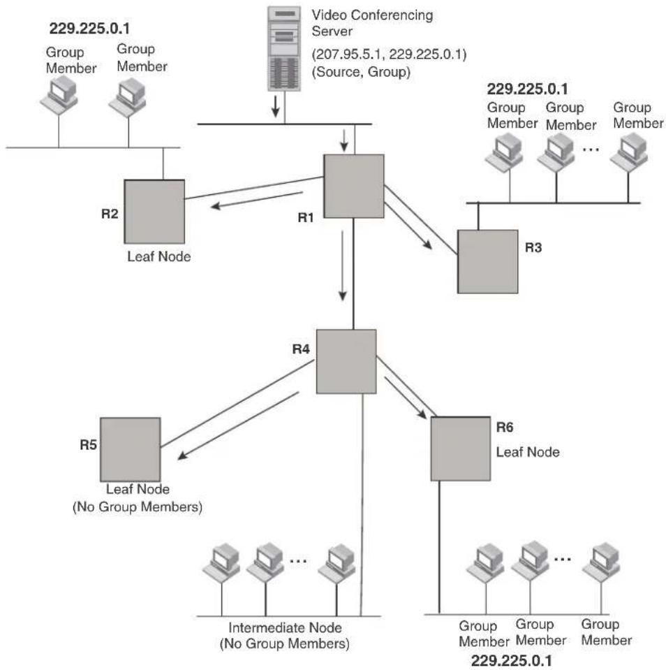
flowchart
graph TD
A["Group Member"] --> B["Leaf Node"]
C["Group Member"] --> B
D["Video Conferencing Server (207.95.5.1, 229.225.0.1) (Source, Group)"] --> E["Node"]
F["Group Member"] --> G["Leaf Node"]
H["Group Member"] --> I["Leaf Node"]
J["Group Member"] --> K["Leaf Node"]
L["Intermediate Node (No Group Members)"] --> M["Leaf Node (No Group Members)"]
N["Intermediate Node (No Group Members)"] --> O["Leaf Node (No Group Members)"]
P["Intermediate Node (No Group Members)"] --> Q["Leaf Node (No Group Members)"]
R["Group Member"] --> S["Leaf Node"]
T["Group Member"] --> U["Leaf Node"]
V["Group Member"] --> W["Leaf Node"]
X["Group Member"] --> Y["Leaf Node"]
Z["Group Member"] --> AA["Leaf Node"]
AB["Group Member"] --> AC["Leaf Node"]
AD["Group Member"] --> AE["Leaf Node"]
AF["Group Member"] --> AG["Leaf Node"]
AH["Group Member"] --> AI["Leaf Node"]
AJ["Group Member"] --> AK["Leaf Node"]
AL["Group Member"] --> AM["Leaf Node"]
AN["Group Member"] --> AO["Leaf Node"]
AP["Group Member"] --> AQ["Leaf Node"]
AR["Group Member"] --> AS["Leaf Node"]
AT["Group Member"] --> AU["Leaf Node"]
AV["Group Member"] --> AW["Leaf Node"]
AX["Group Member"] --> AY["Leaf Node"]
AZ["Group Member"] --> BA["Leaf Node"]
BB["Group Member"] --> BC["Leaf Node"]
BD["Group Member"] --> BE["Leaf Node"]
BF["Group Member"] --> BG["Leaf Node"]
BH["Group Member"] --> BI["Leaf Node"]
BJ["Group Member"] --> BK["Leaf Node"]
BL["Group Member"] --> BM["Leaf Node"]
BN["Group Member"] --> BO["Leaf Node"]
BP["Group Member"] --> BQ["Leaf Node"]
BR["Group Member"] --> BS["Leaf Node"]
BT["Group Member"] --> BU["Leaf Node"]
BV["Group Member"] --> BW["Leaf Node"]
BX["Group Member"] --> BY["Leaf Node"]
BZ["Group Member"] --> BQ
CA["Group Member"] --> BQ
CB["Group Member"] --> BQ
CC["Group Member"] --> BQ
DD["Group Member"] --> BQ
DB["Group Member"] --> BQ
FIGURE 91 Pruning leaf nodes from a multicast tree
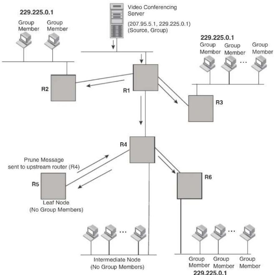
flowchart
graph TD
A["Group Member"] --> B["R2"]
C["Group Member"] --> B
D["Video Conferencing Server (207.95.5.1, 229.225.0.1) (Source, Group)"] --> E["R1"]
E --> F["R4"]
G["Group Member"] --> H["R3"]
I["Group Member"] --> H
J["Group Member"] --> H
K["Intermediate Node (No Group Members)"] --> L["R5"]
M["Group Member"] --> N["R6"]
O["Group Member"] --> N
P["Group Member"] --> N
Q["Prune Message sent to upstream router (R4)"] --> R["R4"]
S["Leaf Node (No Group Members)"] --> T["R5"]
U["Other Nodes"] --> V["..."]
W["229.225.0.1"] --> X["229.225.0.1"]
Grafts to a multicast tree
A PIM router restores pruned branches to a multicast tree by sending graft messages towards the upstream router. Graft messages start at the leaf node and travel up the tree, first sending the message to its neighbor upstream router.
In the example above, if a new 229.255.0.1 group member joins on router R6, which was previously pruned, a graft is sent upstream to R4. Since the forwarding state for this entry is in a prune state, R4 sends a graft to R1. Once R4 has joined the tree, R4 along with R6 once again receive multicast packets.
Prune and graft messages are continuously used to maintain the multicast delivery tree. No configuration is required on your part.
PIM DM versions
The BigIron RX supports PIM DM V1 and V2. The default is V2. You can specify the version on an individual interface basis.
The primary difference between PIM DM V1 and V2 is the methods the protocols use for messaging:
- PIM DM V1 - uses the IGMP to send messages.
- PIM DM V2 – sends messages to the multicast address 224.0.0.13 (ALL-PIM-ROUTERS) with protocol number 103.
The CLI commands for configuring and managing PIM DM are the same for V1 and V2. The only difference is the command you use to enable the protocol on an interface.
NOTE
If you want to continue to use PIM DM V1 on an interface, you must change the version, then save the configuration.
NOTE
The note above does not mean you can run different PIM versions on devices that are connected to each other. The devices must run the same version of PIM. If you want to connect a device running PIM to a device that is running PIM V1, you must change the PIM version on the device to V1 (or change the version on the device to V2, if supported).
Configuring PIM DM
NOTE
This section describes how to configure the “dense” mode of PIM, described in RFC 1075. Refer to “Configuring PIM Sparse” on page 607 for information about configuring PIM Sparse.
Enabling PIM on the router and an interface
By default, PIM is disabled. To enable PIM:
- Enable the feature globally.
- Configure the IP interfaces that will use PIM.
- Enable PIM locally on the ports that have the IP interfaces you configured for PIM.
- Reload the software to place PIM into effect.
Suppose you want to initiate the use of desktop video for fellow users on a sprawling campus network. All destination workstations have the appropriate hardware and software but the Brocade routers that connect the various buildings need to be configured to support PIM multicasts from the designated video conference server as shown in Figure 90 on page 599.
PIM is enabled on each of the Brocade routers shown in Figure 90, on which multicasts are expected. You can enable PIM on each router independently or remotely from one of the routers with a Telnet connection. Follow the same steps for each router. A reset of the router is required when PIM is first enabled. Thereafter, all changes are dynamic.
Globally enabling and disabling PIM
To globally enable PIM, enter the following command.
BigIron RX(config)# router pim
Syntax: [no] router pim
The behavior of the [no] router pim command was as follows:
- Entering router pim command to enable PIM does not require a software reload.
- Entering a no router pim command removes all configuration for PIM multicast on a BigIron RX (router pim level) only.
Enabling a PIM version
To enable PIM on an interface, globally enable PIM, then enable PIM on interface 1/3, enter the following commands.
BigIron RX(config)# router pim
BigIron RX(config)# int e 1/3
BigIron RX(config-if-e10000-1/3)# ip address 207.95.5.1/24
BigIron RX(config-if-e10000-1/3)# ip pim
BigIron RX(config-if-e10000-1/3)# write memory
BigIron RX(config-if-e10000-1/3)# end
Syntax: [no] ip pim [version 1 | 2]
The version 1 | 2 parameter specifies the PIM DM version. The default version is 2.
If you have enabled PIM version 1 but need to enable version 2 instead, enter either of the following commands at the configuration level for the interface.
BigIron RX(config-if-e10000-1/1)# ip pim version 2
BigIron RX(config-if-e10000-1/1)# no ip pim version 1
To disable PIM DM on the interface, enter the following command.
BigIron RX(config-if-e10000-1/1)# no ip pim
Modifying PIM global parameters
PIM global parameters come with preset values. The defaults work well in most networks, but you can modify the following parameters if you need to:
- Neighbor timeout
- Hello timer
- Prune timer
- Prune wait timer
- Graft retransmit timer
- Inactivity timer
Modifying neighbor timeout
Neighbor timeout is the interval after which a PIM router will consider a neighbor to be absent. Absence of PIM hello messages from a neighboring router indicates that a neighbor is not present.
The default value is 180 seconds.
To apply a PIM neighbor timeout value of 360 seconds to all ports on the router operating with PIM, enter the following.
BigIron RX(config)# router pim
BigIron RX(config-pim-router)# nbr-timeout 360
Syntax: nbr-timeout <60-8000>
The default is 180 seconds.
Modifying hello timer
This parameter defines the interval at which periodic hellos are sent out PIM interfaces. Routers use hello messages to inform neighboring routers of their presence. The default rate is 60 seconds.
To apply a PIM hello timer of 120 seconds to all ports on the router operating with PIM, enter the following.
BigIron RX(config)# router pim
BigIron RX(config-pim-router)# hello-timer 120
Syntax: hello-timer <10-3600>
The default is 60 seconds.
Modifying prune timer
This parameter defines how long a Brocade PIM router will maintain a prune state for a forwarding entry.
The first received multicast interface is forwarded to all other PIM interfaces on the router. If there is no presence of groups on that interface, the leaf node sends a prune message upstream and stores a prune state. This prune state travels up the tree and installs a prune state.
A prune state is maintained until the prune timer expires or a graft message is received for the forwarding entry. The default value is 180 seconds.
To set the PIM prune timer to 90, enter the following.
BigIron RX(config)# router pim
BigIron RX(config-pim-router)# prune-timer 90
Syntax: prune-timer <10-3600>
The default is 180 seconds.
Modifying the prune wait timer
The prune-wait command allows you to configure the amount of time a PIM router will wait before stopping traffic to neighbor routers that do not want the traffic. The value can be from zero to three seconds. The default is three seconds. A smaller prune wait value reduces flooding of unwanted traffic.
A prune wait value of zero causes the PIM router to stop traffic immediately upon receiving a prune message. If there are two or more neighbors on the physical port, then the prune-wait command should not be used because one neighbor may send a prune message while the other sends a join message at the during time or in less than three seconds.
To set the prune wait time to zero, enter the following commands.
BigIron RX(config)# router pim
BigIron RX(config-pim-router)# prune-wait 0
Syntax: prune-wait
Where
Viewing the prune wait time
To view the prune wait time, enter the following command at any level of the CLI.
BigIron RX(config)#show ip pim dense
Global PIM Dense Mode Settings
Hello interval: 60, Neighbor timeout: 180
Graft Retransmit interval: 180, Inactivity interval: 180
Route Expire interval: 200, Route Discard interval: 340
Prune age: 180, Prune wait: 3
Syntax: show ip pim dense
Modifying graft retransmit timer
The Graft Retransmit Timer defines the interval between the transmission of graft messages.
A graft message is sent by a router to cancel a prune state. When a router receives a graft message, the router responds with a Graft Ack (acknowledge) message. If this Graft Ack message is lost, the router that sent the graft message will resend it.
To change the graft retransmit timer from the default of 180 to 90 seconds, enter the following.
BigIron RX(config)# router pim
BigIron RX(config-pim-router)# graft-retransmit-timer 90
Syntax: graft-retransmit-timer <60-3600>
The default is 180 seconds.
Modifying inactivity timer
The router deletes a forwarding entry if the entry is not used to send multicast packets. The PIM inactivity timer defines how long a forwarding entry can remain unused before the router deletes it.
To apply a PIM inactivity timer of 90 seconds to all PIM interfaces, enter the following.
BigIron RX(config)# router pim
BigIron RX(config-pim-router)# inactivity-timer 90
Syntax: inactivity-timer <10-3600>
The default is 180 seconds.
Selection of shortest path back to source
By default, when a multicast packet is received on a PIM-capable router interface in a multi-path topology, the interface checks its IP routing table to determine the shortest path back to the source. If the alternate paths have the same cost, the first alternate path in the table is picked as the path back to the source. For example, in the table below, the first four routes have the same cost back to the source. However, 137.80.127.3 will be chosen as the path to the source since it is the first one on the list. The router rejects traffic from any port other than Port V11 on which 137.80.127.3 resides.
| Total number of IP routes: 19 | |||||
| B:BGP D:Connected R:RIP S:Static O:OSPF *:Candidate default | |||||
| Destination | NetMask | Gateway | Port | Cost | |
| Type | |||||
| 9 | 172.17.41.4 | 255.255.255.252*137.80.127.3 | v11 | 2 | |
| O | 172.17.41.4 | 255.255.255.252 | 137.80.126.3 | v10 | 2 |
| O | 172.17.41.4 | 255.255.255.252 | 137.80.129.1 | v13 | 2 |
| O | 172.17.41.4 | 255.255.255.252 | 137.80.128.3 | v12 | 2 |
| O | 172.17.41.8 | 255.255.255.252 | 0.0.0.0 | 1/2 | 1 |
| D | |||||
Failover time in a multi-path topology
Previously, when a port in a multi-path topology fails, multicast routers, depending on the routing protocol being used, take a few seconds to establish a new path, if the failed port is the input port of the downstream router.
No configuration is required for this feature.
Modifying the TTL
The TTL defines the minimum value required in a packet for it to be forwarded out of the interface.
For example, if the TTL for an interface is set at 10, it means that only those packets with a TTL value of 10 or more will be forwarded. Likewise, if an interface is configured with a TTL Threshold value of 1, all packets received on that interface will be forwarded. Possible TTL values are 1 to 64. The default TTL value is 1.
To configure a TTL of 45, enter the following.
BigIron RX(config-if-e10000-3/24)# ip pim ttl 45
Syntax: ip pim ttl <1-64>
PIM Sparse
The BigIron RX supports Protocol Independent Multicast (PIM) Sparse version 2. PIM Sparse provides multicasting that is especially suitable for widely distributed multicast environments. The Brocade implementation is based on RFC 2362.
In a PIM Sparse network, a PIM Sparse router that is connected to a host that wants to receive information for a multicast group must explicitly send a join request on behalf of the receiver (host).
PIM Sparse routers are organized into domains. A PIM Sparse domain is a contiguous set of routers that all implement PIM and are configured to operate within a common boundary. Figure 92 shows a simple example of a PIM Sparse domain. This example shows three BigIron RX devices configured as PIM Sparse routers. The configuration is described in detail following the figure.
FIGURE 92 Example PIM Sparse domain

flowchart
graph TD
A["PIM Sparse router A PIM Sparse router C"] -->|209.157.24.162| B["Source for Group 239.255.162.1"]
A -->|VE 1 207.95.6.1| C["Port38 207.95.8.1"]
C --> D["Rendezvous Point (RP) path"]
D --> E["Port2/1 207.95.8.10"]
D --> F["Port2/2 207.95.7.1"]
F --> G["Port38 207.95.7.2"]
G --> H["Receiver for Group 239.255.162.1"]
I["PIM Sparse router B"] --> J["This interface is also the Bootstrap Router (BR) for this PIM Sparse domain, and the Rendezvous Point (RP) for the PIM Sparse groups in this domain."]
J --> K["Shortest Path Tree (SPT) path"]
K --> L["Port38 207.95.8.1"]
L --> M["Port38 207.95.8.1"]
PIM Sparse router types
Routers that are configured with PIM Sparse interfaces also can be configured to fill one or more of the following roles:
- PMBR - A PIM router that has some interfaces within the PIM domain and other interface outside the PIM domain. PBMRs connect the PIM domain to the Internet.
NOTE
You cannot configure a Brocade routing interface as a PMBR interface for PIM Sparse in the current software release.
- BSR – The Bootstrap Router (BSR) distributes RP information to the other PIM Sparse routers within the domain. Each PIM Sparse domain has one active BSR. For redundancy, you can configure ports on multiple routers as candidate BSRs. The PIM Sparse protocol uses an election process to select one of the candidate BSRs as the BSR for the domain. The BSR with the highest BSR priority (a user-configurable parameter) is elected. If the priorities result in a tie, then the candidate BSR interface with the highest IP address is elected. In the example in Figure 92, PIM Sparse router B is the BSR. Port 2/2 is configured as a candidate BSR.
- RP – The RP is the rendezvous point for PIM Sparse sources and receivers. A PIM Sparse domain can have multiple RPs, but each PIM Sparse multicast group address can have only one active RP. PIM Sparse routers learn the addresses of RPs and the groups for which they are responsible from messages that the BSR sends to each of the PIM Sparse routers. In the example in Figure 92, PIM Sparse router B is the RP. Port 2/2 is configured as a candidate Rendezvous Point (RP).
To enhance overall network performance, BigIron RX use the RP to forward only the first packet
from a group source to the group's receivers. After the first packet, the BigIron RX calculates the shortest path between the receiver and source (the Shortest Path Tree, or SPT) and uses the SPT for subsequent packets from the source to the receiver. The BigIron RX calculates a separate SPT for each source-receiver pair.
NOTE
Brocade recommends that you configure the same ports as candidate BSRs and RPs.
RP paths and SPT paths
Figure 92 shows two paths for packets from the source for group 239.255.162.1 and a receiver for the group. The source is attached to PIM Sparse router A and the recipient is attached to PIM Sparse router C. PIM Sparse router B in is the RP for this multicast group. As a result, the default path for packets from the source to the receiver is through the RP. However, the path through the RP sometimes is not the shortest path. In this case, the shortest path between the source and the receiver is over the direct link between router A and router C, which bypasses the RP (router B).
To optimize PIM traffic, the protocol contains a mechanism for calculating the Shortest Path Tree (SPT) between a given source and receiver. PIM Sparse routers can use the SPT as an alternative to using the RP for forwarding traffic from a source to a receiver. By default, the BigIron RX forwards the first packet they receive from a given source to a given receiver using the RP path, but forward subsequent packets from that source to that receiver through the SPT. In Figure 92, BigIron RX A forwards the first packet from group 239.255.162.1's source to the destination by sending the packet to router B, which is the RP. Router B then sends the packet to router C. For the second and all future packets that router A receives from the source for the receiver, router A forwards them directly to router C using the SPT path.
NOTE
Brocade recommends that you configure the same ports as candidate BSRs and RPs
Configuring PIM Sparse
To configure a BigIron RX for PIM Sparse, perform the following tasks:
- Configure the following global parameter:
- Enable the PIM Sparse mode of multicast routing.
- Configure the following interface parameters:
- Configure an IP address on the interface
- Enable PIM Sparse.
- Identify the interface as a PIM Sparse border, if applicable.
NOTE
You cannot configure a Brocade routing interface as a PMBR interface for PIM Sparse in the current software release.
- Configure the following PIM Sparse global parameters:
- Identify the BigIron RX as a candidate PIM Sparse Bootstrap Router (BSR), if applicable.
- Identify the BigIron RX as a candidate PIM Sparse Rendezvous Point (RP), if applicable.
- Specify the IP address of the RP (if you want to statically select the RP).
NOTE
Brocade recommends that you configure the same BigIron RX as both the BSR and the RP.
Current limitations
The implementation of PIM Sparse in the current software release has the following limitations:
- PIM Sparse and regular PIM (dense mode) cannot be used on the same interface.
- You cannot configure or display PIM Sparse information using the Web management interface. (You can display some general PIM information, but not specific PIM Sparse information.)
Configuring global PIM Sparse parameters
NOTE
When PIM routing is enabled on a BigIron RX, the line rate for receive traffic is reduced by about 5%. The reduction occurs due to overhead from the VLAN multicasting feature, which PIM routing uses. This behavior is normal and does not indicate a problem with the device.
To configure basic global PIM Sparse parameters, enter commands such as the following on each BigIron RX within the PIM Sparse domain.
BigIron RX(config)# router pim
Syntax: [no] router pim
NOTE
You do not need to globally enable IP multicast routing when configuring PIM Sparse.
The command in this example enables IP multicast routing, and enables the PIM Sparse mode of IP multicast routing. The command does not configure the BigIron RX as a candidate PIM Sparse Bootstrap Router (BSR) and candidate Rendezvous Point (RP). You can configure a BigIron RX as a PIM Sparse router without configuring the BigIron RX as a candidate BSR and RP. However, if you do configure the BigIron RX as one of these, Brocade recommends that you configure the BigIron RX as both of these. Refer to “Configuring BSRs” on page 609.
Entering a [no] router pim command does the following:
• Disables PIM or DVMRP.
- Removes all configuration for PIM multicast on a BigIron RX (router pim level) only.
Configuring PIM interface parameters
After you enable IP multicast routing and PIM Sparse at the global level, you must enable it on the individual interfaces connected to the PIM Sparse network.
To enable PIM Sparse mode on an interface, enter commands such as the following.
BigIron RX(config)# interface ethernet 2/2 BigIron RX(config-if-e10000-2/2)# ip address 207.95.7.1 255.255.255.0 BigIron RX(config-if-e10000-2/2)# ip pim-sparse
Syntax: [no] ip pim-sparse
The commands in this example add an IP interface to port 2/2, then enable PIM Sparse on the interface.
If the interface is on the border of the PIM Sparse domain, you also must enter the following command.
BigIron RX(config-if-e10000-2/2)# ip pim border
Syntax: [no] ip pim border
NOTE
You cannot configure a Brocade routing interface as a PMBR interface for PIM Sparse in the current software release.
Configuring BSRs
In addition to the global and interface parameters in the sections above, you need to identify an interface on at least one BigIron RX as a candidate PIM Sparse Bootstrap router (BSR) and candidate PIM Sparse Rendezvous Point (RP).
NOTE
It is possible to configure the BigIron RX as only a candidate BSR or RP, but Brocade recommends that you configure the same interface on the same BigIron RX as both a BSR and an RP.
This section presents how to configure BSRs. Refer to “Configuring RPs” on page 609 for instructions on how to configure RPs.
To configure the BigIron RX as a candidate BSR, enter commands such as the following.
BigIron RX(config)# router pim
BigIron RX(config-pim-router)# bsr-candidate ethernet 2/2 30 255
BSR address: 207.95.7.1, hash mask length: 30, priority: 255
This command configures the PIM Sparse interface on port 2/2 as a BSR candidate, with a hash mask length of 30 and a priority of 255. The information shown in italics above is displayed by the CLI after you enter the candidate BSR configuration command.
Syntax: [no] bsr-candidate ethernet
The ethernet
- Enter ethernet
/ for a physical interface (port). - Enter ve
for a virtual interface. - Enter loopback
for a loopback interface.
The
The
Configuring RPs
Enter a command such as the following to configure the BigIron RX as a candidate RP.
BigIron RX(config-pim-router)# rp-candidate ethernet 2/2
Syntax: [no] rp-candidate ethernet
The ethernet
- Enter ethernet
/ for a physical interface (port). - Enter ve
for a virtual interface. - Enter loopback
for a loopback interface.
By default, this command configures the BigIron RX as a candidate RP for all group numbers beginning with 224. As a result, the BigIron RX is a candidate RP for all valid PIM Sparse group numbers. You can change this by adding or deleting specific address ranges. The following example narrows the group number range for which the BigIron RX is a candidate RP by explicitly adding a range.
BigIron RX(config-pim-router)# rp-candidate add 224.126.0.0 16
Syntax: [no] rp-candidate add
The
You also can change the group numbers for which the BigIron RX is a candidate RP by deleting address ranges. For example, to delete all addresses from 224.126.22.0 - 224.126.22.255, enter the following command.
BigIron RX(config-pim-router)# rp-candidate delete 224.126.22.0 24
Syntax: [no] rp-candidate delete
The usage of the
If you enter both commands shown in the example above, the net effect is that the BigIron RX becomes a candidate RP for groups 224.126.0.0 - 224.126.21.255 and groups 224.126.23.0 - 224.126.255.255.
Updating PIM-Sparse forwarding entries with new RP configuration
If you make changes to your static RP configuration, the entries in the PIM-Sparse multicast forwarding table continue to use the old RP configuration until they are aged out.
The clear pim rp-map command allows you to update the entries in the static multicast forwarding table immediately after making RP configuration changes. This command is meant to be used with rp-address command.
To update the entries in a PIM sparse static multicast forwarding table with new RP configuration, enter the following command at the privileged EXEC level of the CLI.
BigIron RX(config)# clear pim rp-map
Syntax: clear pim rp-map
Statically specifying the RP
Brocade recommends that you use the PIM Sparse protocol's RP election process so that a backup RP can automatically take over if the active RP router becomes unavailable. However, if you do not want the RP to be selected by the RP election process but instead you want to explicitly identify the RP by its IP address, use the rp-address command.
If you explicitly specify the RP, the BigIron RX uses the specified RP for all group-to-RP mappings and overrides the set of candidate RPs supplied by the BSR.
NOTE
Specify the same IP address as the RP on all PIM Sparse routers within the PIM Sparse domain. Make sure the router is on the backbone or is otherwise well connected to the rest of the network.
To specify the IP address of the RP, enter commands such as the following.
BigIron RX(config)# router pim
BigIron RX(config-pim-router)# rp-address 207.95.7.1
Syntax: [no] rp-address
The
The command in the example above identifies the router interface at IP address 207.95.7.1 as the RP for the PIM Sparse domain. The BigIron RX will use the specified RP and ignore group-to-RP mappings received from the BSR.
ACL based RP assignment
The rp-address command allows multiple static RP configurations. For each static RP, an ACL can be given as an option to define the multicast address ranges that the static RP permit or deny to serve.
A static RP by default serves the range of 224.0.0.0/4 if the RP is configured without an ACL name. If an ACL name is given but the ACL is not defined, the static RP is set to inactive mode and it will not cover any multicast group ranges.
The optional static RP ACL can be configured as a standard ACL or as an extended ACL. For an extended ACL, the destination filter will be used to derive the multicast group range and all other filters are ignored. The content of the ACL needs to be defined in the order of prefix length; the longest prefix must be placed at the top of the ACL definition.
If there are overlapping group ranges among the static RPs, the static RP with the longest prefix match will be selected. If more than one static RP covers the exact same group range, the highest IP static RP will be used.
Configuration considerations
- The Static RP has higher precedence over RP learnt from the BSR.
- There is a limit of 32 static RPs in the systems.
Configuring an ACL based RP assignment
To configure an ACL based RP assignment; enter commands such as the following.
BigIron RX(config)# router pim
BigIron RX(config-pim-router)# rp-address 130.1.1.1 acl1
Syntax: rp-address
Use the ip address parameter to specify the IP address of the router you want to designate as an RP router.
Use the acl name or id (optional) parameter to specify the name or ID of the ACL that specifies which multicast groups use this RP.
Displaying the static RP
Use the show ip pim rp-set command to display static RP and the associated group ranges.
BigIron RX(config)# show ip pim rp-set
Static RP and associated group ranges
Static RP count: 4
130.1.1.1
permit 238.1.1.0/24
permit 239.1.0.0/16
permit 235.0.0.0/8
120.1.1.1
deny all
120.2.1.1
deny all
124.1.1.1
permit 224.0.0.0/4
Number of group prefixes Learnt from BSR: 0
No RP-Set present.
Use the show ip pim rp-map command to display all current multicast group addresses to RP address mapping.
BigIron RX(config)# show ip pim rp-map
Number of group-to-RP mappings: 5
Group address RP address
Route selection precedence for multicast
he route-precedence command allows the user to specify a precedence table that dictates how routes are selected for multicast.
PIM must be enabled at the global level.
Configuring the route precedence by specifying the route types
The route precedence {mc-non-default mc-default uc-non-default uc-default none} * command allows you to control the selection of routes based on the route types. There are four different types of routes:
• Non-default route from the mRTM
- Default route from the mRTM
• Non-default route from the uRTM
- Default route from the uRTM
Using this command you may specify an option for all of the precedence levels.
To specify a non-default route from the mRTM, then a non-default route from the uRTM, then a default route from the mRTM, and then a default route from the uRTM, enter commands such as the following.
BigIron RX(config)# router pim
BigIron RX(config-pim-router)# route-precedence mc-non-default uc-non-default mcdefault uc-default
The none option may be used to fill up the precedence table in order to ignore certain types of routes. To use the unicast default route for multicast, enter commands such as the following.
BigIron RX(config)# router pim
BigIron RX(config-pim-router)#route-precedence mc-non-default mc-default uc-non-default none
Syntax: [no] route-precedence {mc-non-default mc-default uc-non-default uc-default none}
Default value: route-precedence mc-non-default mc-default uc-non-default uc-default
Use the mc-non-default parameter to specify a multicast non-default route.
Use the mc-default parameter to specify a multicast default route.
Use the uc-non-default parameter to specify a unicast non-default route.
Use the uc-default parameter to specify a unicast default route.
Use the none parameter to ignore certain types of routes.
The no form of this command removes the configuration.
Displaying the route selection
Use the show ip pim sparse command to display the current route selection. The example below displays the default route precedence selection.
BigIron RX(config)#show ip pim sparse
Global PIM Sparse Mode Settings
Hello interval : 30 Neighbor timeout : 105
Bootstrap Msg interval: 60 Candidate-RP Advertisement interval: 60
Join/Prune interval : 60 SPT Threshold : 1
Inactivity interval : 180 SSM Enabled : No
Hardware Drop Enabled : Yes
Route Selection : mc-non-default mc-default uc-non-default uc-default
| Interface | LocalAddress | Mode | Ver | Designated Router | TTLThresh | MulticastBoundary | |
| Address | Port | ||||||
| v12 | 100.4.8.2 | SM | V2 | Itself | 1 | None | |
| v13 | 100.16.8.2 | SM | V2 | Itself | 1 | None | |
| v124 | 124.0.0.1 | SM | V2 | Itself | 1 | None | |
| v125 | 125.0.0.1 | SM | V2 | Itself | 1 | None | |
| v126 | 126.0.0.1 | SM | V2 | Itself | 1 | None | |
| v127 | 127.0.0.1 | SM | V2 | Itself | 1 | None | |
| l1 | 1.0.8.1 | SM | V2 | Itself | 1 | None | |
This example displays the route precedence selection as multicast non-default, then unicast non-default, then multicast default, and then unicast default.
BigIron RX(config-pim-router)#show ip pim sparse
Global PIM Sparse Mode Settings
Hello interval : 30 Neighbor timeout : 105
Bootstrap Msg interval: 60 Candidate-RP Advertisement interval: 60
Join/Prune interval : 60 SPT Threshold : 1
Inactivity interval : 180 SSM Enabled : No
Hardware Drop Enabled : Yes
Route Selection : mc-non-default uc-non-default mc-default uc-default
| Interface | LocalAddress | Mode | Ver | Designated | RouterPort | TTLThresh | MulticastBoundary |
| v12 | 100.4.8.2 | SM | V2 | Itself | 1 | None | |
| v13 | 100.16.8.2 | SM | V2 | Itself | 1 | None | |
| v124 | 124.0.0.1 | SM | V2 | Itself | 1 | None | |
| v125 | 125.0.0.1 | SM | V2 | Itself | 1 | None | |
| v126 | 126.0.0.1 | SM | V2 | Itself | 1 | None | |
| v127 | 127.0.0.1 | SM | V2 | Itself | 1 | None | |
| l1 | 1.0.8.1 | SM | V2 | Itself | 1 | None | |
Changing the Shortest Path Tree (SPT) threshold
In a typical PIM Sparse domain, there may be two or more paths from a DR (designated router) for a multicast source to a PIM group receiver.
- Path through the RP – This is the path the BigIron RX uses the first time it receives traffic for a PIM group. However, the path through the RP may not be the shortest path from the BigIron RX to the receiver.
- Shortest Path – Each PIM Sparse router that is a DR for a multicast source calculates a shortest path tree (SPT) to all the PIM Sparse group receivers within the domain, with the BigIron RX itself as the root of the tree. The first time a BigIron RX is configured as a PIM router and receives a packet for a PIM receiver, the BigIron RX sends the packet to the RP for the group. The BigIron RX also calculates the SPT from itself to the receiver. The next time the BigIron RX receives a PIM Sparse packet for the receiver, the BigIron RX sends the packet toward the receiver using the shortest route, which may not pass through the RP.
By default, the device switches from the RP to the SPT after receiving the first packet for a given PIM Sparse group. The BigIron RX maintains a separate counter for each PIM Sparse source-group pair.
After the BigIron RX receives a packet for a given source-group pair, the BigIron RX starts a PIM data timer for that source-group pair. If the BigIron RX does not receive another packet for the source-group pair before the timer expires, it reverts to using the RP for the next packet received for the source-group pair. In accordance with the PIM Sparse RFC's recommendation, the timer is 210 seconds and is not configurable. The counter is reset to zero each time the BigIron RX receives a packet for the source-group pair.
You can change the number of packets that the BigIron RX sends using the RP before switching to using the SPT.
To change the number of packets the BigIron RX sends using the RP before switching to the SPT, enter commands such as the following.
BigIron RX(config)# router pim
BigIron RX(config-pim-router)# spt-threshold 1000
Syntax: [no] spt-threshold infinity |
The infinity |
Changing the PIM join and prune message interval
By default, the BigIron RX sends PIM Sparse Join/Prune messages every 60 seconds. These messages inform other PIM Sparse routers about clients who want to become receivers (Join) or stop being receivers (Prune) for PIM Sparse groups.
NOTE
Use the same Join/Prune message interval on all the PIM Sparse routers in the PIM Sparse domain. If the routers do not all use the same timer interval, the performance of PIM Sparse can be adversely affected.
To change the Join/Prune interval, enter commands such as the following.
BigIron RX(config)# router pim BigIron RX(config-pim-router)# message-interval 30
Syntax: [no] message-interval
The
MLL optimization
MLL optimization is enabled by default, except for trunks in order that trunk load sharing remains unaffected. The ip multicast-routing optimization of-list trunks command can be used to turn on optimization for trunks such that the degree of 'even balance' may be less than when not optimized.
BigIron RX(config)# ip multicast-routing optimization oif-list trunks
Syntax: ip multicast-routing optimization of-list trunks
Displaying PIM Sparse configuration information and statistics
You can display the following PIM Sparse information:
- Basic PIM Sparse configuration information
- Group information
- BSR information
• Candidate RP information - RP-to-group mappings
• RP information for a PIM Sparse group -
RP set list
• PIM Neighbor information -
The PIM flow cache
• The PIM multicast cache - PIM traffic statistics
Displaying basic PIM Sparse configuration information
To display PIM Sparse configuration information, enter the following command at any CLI level.
BigIron RX(config-pim-router)# show ip pim sparse
Global PIM Sparse Mode Settings Hello interval: 60, Neighbor timeout: 180 Bootstrap Msg interval: 130, Candidate-RP Advertisement interval: 60 Join/Prune interval: 60, SPT Threshold: 1
Interface Ethernet e3/8 TTL Threshold: 1, Enabled Local Address: 207.95.8.1
Interface Ve 1 TTL Threshold: 1, Enabled Local Address: 207.95.6.1
Syntax: show ip pim sparse
This example shows the PIM Sparse configuration information on PIM Sparse router A in Figure 92.
This display shows the following information.
This field... Displays...
| Global PIM Sparse mode settings | |
| Hello interval How frequently the BigIron RX sends PIM Sparse hello messages to itsPIM Sparse neighbors. This field show the number of seconds betweenhello messages. PIM Sparse routers use hello messages to discover oneanother. | |
| Neighbor timeout How many seconds the BigIron RX will wait for a hello message from aneighbor before determining that the neighbor is no longer present andremoving cached PIM Sparse forwarding entries for the neighbor. | |
| Bootstrap Msg interval How frequently the BSR configured on the BigIron RX sends the RP set tothe RPs within the PIM Sparse domain. The RP set is a list of candidatERPs and their group prefixes. A candidate RP’s group prefix indicates therange of PIM Sparse group numbers for which it can be an RP.NOTE:This field contains a value only if an interface on the BigIron RX iselected to be the BSR. Otherwise, the field is blank. |
Candidate-RP Advertisement interval How frequently the candidate PR configured on the BigIron RX sends candidate RP advertisement messages to the BSR.
NOTE: This field contains a value only if an interface on the BigIron RX is configured as a candidate RP. Otherwise, the field is blank.
This field... Displays...
| Join/Prune interval How frequently the BigIron RX sends PIM Sparse Join/Prune messagesfor the multicast groups it is forwarding. This field show the number of seconds between Join/Prune messages.The BigIron RX sends Join/Prune messages on behalf of multicast receivers who want to join or leave a PIM Sparse group. When forwarding packets from PIM Sparse sources, the BigIron RX sends the packets only on the interfaces on which it has received join requests in Join/Prune messages for the source’s group.You can change the Join/Prune interval if needed. Refer to “Changing the PIM join and prune message interval” on page 615. |
| SPT Threshold The number of packets the BigIron RX sends using the path through the RP before switching to using the SPT path. |
PIM Sparse interface information
| NOTE: You also can display IP multicast interface information using the show ip pim interface command. However, this command lists all IP multicast interfaces, including regular PIM (dense mode) and DVMRP interfaces. The show ip pim sparse command lists only the PIM Sparse interfaces. |
| Interface The type of interface and the interface number. The interface type can be one of the following: |
- Ethernet
• VE
The number is either a port number (and slot number if applicable) or the virtual interface (VE) number.
| TTL Threshold Following the TTL threshold value, the interface state is listed. The |
interface state can be one of the following:
- Disabled
- Enabled
Local Address Indicates the IP address configured on the port or virtual interface.
Displaying a list of multicast groups
To display PIM Sparse configuration information, enter the following command at any CLI level.
BigIron RX(config-pim-router)# show ip pim group
Total number of Groups: 2
Index 1 Group 239.255.162.1 Ports e3/11
Syntax: show ip pim group
This display shows the following information.
This field... Displays...
| Total number of Groups Lists the total number of IP multicast groups the BigIron RX is forwarding. |
| NOTE: This list can include groups that are not PIM Sparse groups. If interfaces on the BigIron RX are configured for regular PIM (dense mode) or DVMRP, these groups are listed too. |
Index The index number of the table entry in the display.
This field... Displays...
Group The multicast group address
Ports The BigIron RX ports connected to the receivers of the groups.
Displaying BSR information
To display BSR information, enter the following command at any CLI level.
BigIron RX(config-pim-router)# show ip pim bsr
PIMv2 Bootstrap information
This system is the elected Bootstrap Router (BSR)
BSR address: 207.95.7.1
Uptime: 00:33:52, BSR priority: 5, Hash mask length: 32
Next bootstrap message in 00:00:20
Next Candidate-RP-advertisement in 00:00:10
RP: 207.95.7.1
group prefixes:
224.0.0.0 / 4
Candidate-RP-advertisement period: 60
This example show information displayed on a BigIron RX that has been elected as the BSR. The following example shows information displayed on a BigIron RX that is not the BSR. Notice that some fields shown in the example above do not appear in the example below.
BigIron RX(config-pim-router)# show ip pim bsr
PIMv2 Bootstrap information
BSR address = 207.95.7.1
BSR priority = 5
Syntax: show ip pim bsr
This display shows the following information.
This field... Displays...
BSR address The IP address of the interface configured as the PIM Sparse Bootstrap
Router (BSR).
Uptime The amount of time the BSR has been running.
NOTE: This field appears only if this BigIron RX is the BSR.
BSR priority The priority assigned to the interface for use during the BSR election
process. During BSR election, the priorities of the candidate BSRs are compared and the interface with the highest BSR priority becomes the BSR.
Hash mask length The number of significant bits in the IP multicast group comparison
mask. This mask determines the IP multicast group numbers for which the BigIron RX can be a BSR. The default is 32 bits, which allows the BigIron RX to be a BSR for any valid IP multicast group number.
NOTE: This field appears only if this BigIron RX is a candidate BSR.
This field... Displays...
| Next bootstrap message in | NOTE: Indicates how many seconds will pass before the BSR sends its next Bootstrap message. NOTE: This field appears only if this BigIron RX is the BSR. |
| Next Candidate-RP-advertisement message in | Indicates how many seconds will pass before the BSR sends its next candidate PR advertisement message. NOTE: This field appears only if this BigIron RX is a candidate BSR. |
| RP Indicates the IP address of the Rendezvous Point (RP). NOTE: This field appears only if this BigIron RX is a candidate BSR. | |
| group prefixes Indicates the multicast groups for which the RP listed by the previous field is a candidate RP. NOTE: This field appears only if this BigIron RX is a candidate BSR. | |
| Candidate-RP-advertisement period | Indicates how frequently the BSR sends candidate RP advertisement messages. NOTE: This field appears only if this BigIron RX is a candidate BSR. |
Displaying candidate RP information
To display candidate RP information, enter the following command at any CLI level.
BigIron RX(config-pim-router)# show ip pim rp-candidate
Next Candidate-RP-advertisement in 00:00:10
RP: 207.95.7.1
group prefixes:
224.0.0.0 / 4
Candidate-RP-advertisement period: 60
This example shows information displayed on a BigIron RX that is a candidate RP. The following example shows the message displayed on a BigIron RX that is not a candidate RP.
BigIron RX(config-pim-router)# show ip pim rp-candidate
This system is not a Candidate-RP.
Syntax: show ip pim rp-candidate
This display shows the following information.
This field... Displays...
| Candidate-RP-advertisement in Indicates how many seconds will pass before the BSR sends its next RP message. |
| NOTE: This field appears only if this BigIron RX is a candidate RP. |
RP Indicates the IP address of the Rendezvous Point (RP).
NOTE: This field appears only if this BigIron RX is a candidate RP.
This field... Displays...
| group prefixes Indicates the multicast groups for which the RP listed by the previous field is a candidate RP. | |
| NOTE: This field appears only if this BigIron RX is a candidate RP. | |
| Candidate-RP-advertisement period | Indicates how frequently the BSR sends candidate RP advertisement messages. |
| NOTE: This field appears only if this BigIron RX is a candidate RP. | |
Displaying RP-to-group mappings
To display RP-to-group-mappings, enter the following command at any CLI level.
BigIron RX(config-pim-router)# show ip pim rp-map Number of group-to-RP mappings: 6
Group address RP address
| 1 | 239.255.163.1 | 99.99.99.5 |
| 2 | 239.255.163.2 | 99.99.99.5 |
| 3 | 239.255.163.3 | 99.99.99.5 |
| 4 | 239.255.162.1 | 99.99.99.5 |
| 5 | 239.255.162.2 | 43.43.43.1 |
| 6 | 239.255.162.3 | 99.99.99.5 |
Syntax: show ip pim rp-map
This display shows the following information.
This field... Displays...
| Group address Indicates the PIM Sparse multicast group address using the listed RP. |
| RP address Indicates the IP address of the Rendezvous Point (RP) for the listed PIM Sparse group. |
Displaying RP information for a PIM Sparse group
To display RP information for a PIM Sparse group, enter the following command at any CLI level.
BigIron RX(config-pim-router)# show ip pim rp-hash 239.255.162.1
RP: 207.95.7.1, v2 Info source: 207.95.7.1, via bootstrap
Syntax: show ip pim rp-hash
The
This display shows the following information.
This field... Displays...
| RP Indicates the IP address of the Rendezvous Point (RP) for the specified PIM Sparse group.Following the IP address is the port or virtual interface through which this BigIron RX learned the identity of the RP. |
| Info source Indicates the IP address on which the RP information was received.Following the IP address is the method through which this BigIron RX learned the identity of the RP. |
Displaying the RP set list
To display the RP set list, enter the following command at any CLI level.
BigIron RX(config)#show ip pim rp-set Group address Static-RP-address Override
Access-List 44 99.99.99.5 On Number of group prefixes Learnt from BSR: 1 Group prefix = 239.255.162.0/24 # RPs expected: 1
RPs received: 1
RP 1: 43.43.43.1 priority=0 age=0
Syntax: show ip pim rp-set
This display shows the following information.
This field... Displays...
| Number of group prefixes The number of PIM Sparse group prefixes for which the RP is responsible. | |
| Group prefix Indicates the multicast groups for which the RP listed by the previous field is a candidate RP. | |
| RPs expected/received Indicates how many RPs were expected and received in the latest Bootstrap message. | |
| RP | Indicates the RP number. If there are multiple RPs in the PIM Sparse domain, a line of information for each of them is listed, and they are numbered in ascending numerical order. |
| priority The RP priority of the candidate RP. During the election process, the candidate RP with the highest priority is elected as the RP. | |
| age The age (in seconds) of this RP-set. | NOTE: If this BigIron RX is not a BSR, this field contains zero. Only the BSR ages the RP-set. |
Displaying multicast neighbor information
To display information about the BigIron RX's PIM neighbors, enter the following command at any CLI level.
BigIron RX(config-pim-router)# show ip pim nbr
| Port | Neighbor | Holdtime | Age | UpTime |
| sec | sec | sec | ||
| e3/8 | 207.95.8.10 | 180 | 60 | 900 |
| Port | Neighbor | Holdtime | Age | UpTime |
| sec | sec | sec | ||
| v1 | 207.95.6.2 | 180 | 60 | 900 |
Syntax: show ip pim nbr
This display shows the following information.
This field... Displays...
Port The interface through which the BigIron RX is connected to the neighbor.
Neighbor The IP interface of the PIM neighbor interface.
Holdtime sec Indicates how many seconds the neighbor wants this BigIron RX to hold
the entry for this neighbor in memory. The neighbor sends the Hold Time in its Hello packets.
- If the BigIron RX receives a new Hello packet before the Hold Time received in the previous packet expires, the BigIron RX updates its table entry for the neighbor.
- If the BigIron RX does not receive a new Hello packet from the neighbor before the Hold time expires, the BigIron RX assumes the neighbor is no longer available and removes the entry for the neighbor.
Age sec The number of seconds since the BigIron RX received the last hello message from the neighbor.
UpTime sec The number of seconds the PIM neighbor has been up. This timer starts
when the BigIron RX receives the first Hello messages from the neighbor.
Displaying information about an upstream neighbor device
You can view information about the upstream neighbor device for a given source IP address for IP PIM and DVMRP packets. For PIM, the software uses the IP route table or multicast route table to lookup the upstream neighbor device. For DVMRP, the software uses the DVMRP route table to locate the upstream neighbor device.
Enter the following command at the Privileged EXEC level of the CLI.
BigIron RX# show ip pim rpf 1.1.20.2
directly connected or via an L2 neighbor
NOTE
If there are multiple equal cost paths to the source, the show ip pim rpf command output may not be accurate. If your system has multiple equal cost paths, use the command show ip pim mcache to view information about the upstream neighbor.
The following example outputs show other messages that the BigIron RX displays with this command.
BigIron RX# show ip pim rpf 1.2.3.4
no route
BigIron RX# show ip pim rpf 1.10.10.24
upstream neighbor=1.1.20.1 on v21 using ip route
Syntax: show ip pim | dvmrp rpf
Where
Displaying the PIM multicast cache
To display the PIM multicast cache, enter the following command at any CLI level.
BigIron RX(config-pim-router)# show ip pim mcache
Total 6 entries
1 (10.161.32.200, 237.0.0.1) in v87 (tag e3/1), cnt=0
Sparse Mode, RPT=0 SPT=1 Reg=0
upstream neighbor=10.10.8.45
num_oifs = 1 v2
L3 (HW) 1: e4/24(VL2702)
fast=1 slow=0 leaf=0 prun=0 frag=0 tag=0 tnnl=0 swL2=0 hwL2=0 msdp_adv=0
age=0 fid: 0416 l2vidx: none
2 (*, 237.0.0.1) RP10.161.2.1 in v93, cnt=0
Sparse Mode, RPT=1 SPT=0 Reg=0
upstream neighbor=10.10.8.33
num_oifs = 1 v2
L3 (SW) 1: e4/24(VL2702)
fast=1 slow=0 leaf=0 prun=0 frag=0 tag=0 tnnl=0 swL2=0 hwL2=0 msdp_adv=0
age=0 fid: none l2vidx: none
3 (*, 239.255.255.250) RP10.159.2.2 in v87, cnt=0
Sparse Mode, RPT=1 SPT=0 Reg=0
upstream neighbor=10.10.8.45
num_oifs = 1 v2
L3 (SW) 1: e4/23(VL2702)
fast=1 slow=0 leaf=0 prun=0 frag=0 tag=0 tnnl=0 swL2=0 hwL2=0 msdp_adv=0
age=0 fid: none l2vidx: none
4 (137.80.133.220, 224.225.0.3) in v16 (tag e1/3)
upstream neighbor=172.17.42.2
L3 (HW) 2: e1/4(VL15), e1/3(VL11)
L2 (HW) 1: TR(e1/5, e1/6)
fast=1 slow=0 leaf=0 prun=0 frag=0 tag=1 tnnl=0 swL2=0 hwL2=0 msdp_adv=0
age=0 fid: 0409 l2vidx: 040f
5 (137.80.200.124, 224.225.0.4) in v200 (tag e1/3)
Source is directly connected
L3 (HW) 1: e1/4(VL15)
fast=1 slow=0 leaf=0 prun=0 frag=0 tag=1 tnnl=0 swL2=0 hwL2=0 msdp_adv=0
age=0 fid: 0410 l2vidx: none
6 (137.80.134.232, 224.225.0.5) in v16 (tag e1/3)
upstream neighbor=172.17.42.2
L3 (HW) 2: e1/3(VL11), e1/4(VL200)
L2 (HW) 1: TR(e1/5, e1/5)
fast=1 slow=0 leaf=0 prun=0 frag=0 tag=1 tnnl=0 swL2=0 hwL2=0 msdp_adv=0
age=0 fid: 0402 l2vidx: 0408
Syntax: show ip pim mcache
This display shows the following information.
| This field... Displays... | |
| (<source>,<group>) | The comma-separated values in parentheses is a source-group pair.The <source> is the PIM source for the multicast <group>. For example, the following entry means source 209.157.24.162 for group 239.255.162.1: (209.157.24.162,239.255.162.1)If thevalue is * (asterisk), this cache entry uses the RP path. The * value means “all sources”.If theis a specific source address, this cache entry uses the SPT path. |
| RP | Indicates the RP for the group for this cache entry.NOTE: The RP address appears only if the RPT flag is set to 1 and the SPT flag is set to 0 (see below). |
| forward port The port through which the BigIron RX reaches the source. | |
| Count The number of packets forwarded using this cache entry. | |
| Sparse Mode Indicates whether the cache entry is for regular PIM (dense mode) orPIM Sparse. This flag can have one of the following values:0 - The entry is not for PIM Sparse (and is therefore for the dense mode of PIM).1- The entry is for PIM Sparse. | |
| RPT Indicates whether the cache entry uses the RP path or the SPT path. TheRPT flag can have one of the following values:0 - The SPT path is used instead of the RP path.1- The RP path is used instead of the SPT path.NOTE: The values of the RP and SPT flags are always opposite (one is set to 0 and the other is set to 1). | |
| SPT Indicates whether the cache entry uses the RP path or the SPT path. TheSP flag can have one of the following values:0 - The RP path is used instead of the SPT path.1- The SPT path is used instead of the RP path.NOTE: The values of the RP and SPT flags are always opposite (one is set to 0 and the other is set to 1). | |
| Register Suppress Indicates whether the Register Suppress timer is running. This field can have one of the following values:0 - The timer is not running.1 - The timer is running. | |
| member ports Indicates the BigIron RX physical ports to which the receivers for the source and group are attached. The receivers can be directly attached or indirectly attached through other PIM Sparse routers. | |
| virtual ports | Indicates the virtual interfaces to which the receivers for the source and group are attached. The receivers can be directly attached or indirectly attached through other PIM Sparse routers. |
| prune ports | Indicates the physical ports on which the BigIron RX has received a prune notification (in a Join/Prune message) to remove the receiver from the list of recipients for the group. |
| virtual prune ports | Indicates the virtual interfaces ports on which the BigIron RX has received a prune notification (in a Join/Prune message) to remove the receiver from the list of recipients for the group. |
Displaying PIM traffic statistics
To display PIM traffic statistics, enter the following command at any CLI level.
BigIron RX(config-pim-router)# show ip pim traffic
| Port | Hello | J/P | Register | RegStop | Assert | |||||
| [Rx | Tx] | [Rx | Tx] | [Rx | Tx] | [Rx | Tx] | [Rx | Tx] | |
| e3/8 | 19 | 19 | 32 | 0 | 0 | 0 | 37 | 0 | 0 | 0 |
| v1 | 18 | 19 | 0 | 20 | 0 | 0 | 0 | 0 | 0 | 0 |
| v2 | 0 | 19 | 0 | 0 | 0 | 16 | 0 | 0 | 0 | 0 |
| Total | 37 | 57 | 32 | 0 | 0 | 0 | 0 | 0 | 0 | 0 |
IGMP Statistics:
Total Recv/Xmit 85/110
Total Discard/chksum 0/0
Syntax: show ip pim traffic
NOTE
If you have configured interfaces for standard PIM (dense mode) on the BigIron RX, statistics for these interfaces are listed first by the display.
This display shows the following information.
This field... Displays...
| Port The port or virtual interface on which the PIM interface is configured. |
| Hello The number of PIM Hello messages sent or received on the interface. |
| J/P The number of Join/Prune messages sent or received on the interface.NOTE: Unlike PIM dense, PIM Sparse uses the same messages for Joins and Prunes. |
| Register The number of Register messages sent or received on the interface. |
| RegStop The number of Register Stop messages sent or received on the interface. |
| Assert The number of Assert messages sent or received on the interface. |
| Total Recv/Xmit The total number of IGMP messages sent and received by the BigIron RX. |
| Total Discard/chksum The total number of IGMP messages discarded, including a separate counter for those that failed the checksum comparison. |
PIM-SSMv4
Source Specific mode is similar to Sparse mode, but instead of simply joining a group, the receiver uses IGMPv3 messages to join a group sent from a specific source. This way, instead of the receiver getting multiple copies of the same stream from multiple sources, it will only receive traffic from the one source to which it joins.
The amount of unwanted traffic in the network is reduced, but because each multicast group is associated with a particular host, different hosts can be assigned the same multicast address for different streams. This greatly increases the number of multicast groups that can be used in the network. Another added benefit of SSM is that it increases security by reducing the possibility of a rogue source disrupting the traffic from a legitimate source.
SSM defines a Short Path Tree (SPT) for multicast traffic. If SSM is enabled, the SPT is identified by an (S,G) pair, where S is a source address and G is an SSM destination address. If the SSM protocol is not enabled and before the SPT switchover, the multicast switch creates one (*, G) entry for the entire multicast group, which can have many sources. The SSM SPT is on a per-source basis and allows a client to receive multicast traffic directly from the source; that is, all joins and leaves are source-specific. You are also able to configure a specific SSM path.
SSM is limited to multicast group addresses in the 224.0.1.0 through 239.255.255.255 address range. If PIM Sparse is used as the multicast protocol, the SSM protocol should be enabled if you want to filter unwanted traffic before the Shortest Path Tree protocol switchover occurs for groups in the 232/8 range. Not configuring the SSM protocol in PIM Sparse may cause the switch or router to leak unwanted packets with the same group, but containing undesired sources, to clients. After SPT switch over, the leak stops and source specific multicast works correctly even without configuring the SSM protocol.
If the SSM protocol is enabled, one (S,G) entry is created for every source of the multicast group, even for sources with non-existent traffic. For example, if there are 1,000 sources in the group, 1,000 (S,G) entries will be created. Therefore, enabling the SSM protocol for PIM-SM requires more software resources than leaving the protocol disabled.
Enabling SSM
To enable the SSM protocol, IGMP v3 and PIM-SM must be enabled. Enter the ssm-enable command under the router pim level to globally enable the SSM protocol on the device.
BigIron RX(config)# ipv6 router pim BigIron RX(config-ipv6-pim-router)# ssm-enable
Syntax: [no] ssm-enable [range <ip-address-prefix/
Enter the IP address range <ip-address-prefix /
Configuring Multicast Source Discovery Protocol (MSDP)
The Multicast Source Discovery Protocol (MSDP) is used by Protocol Independent Multicast (PIM) Sparse routers to exchange routing information for PIM Sparse multicast groups across PIM Sparse domains. Routers running MSDP can discover PIM Sparse sources that are in other PIM Sparse domains.
PIM Sparse routers use MSDP to register PIM Sparse multicast sources in a domain with the Rendezvous Point (RP) for that domain.
Figure 93 shows an example of some PIM Sparse domains. For simplicity, this example show only one Designated Router (DR), one group source, and one receiver for the group. Only one PIM Sparse router within each domain needs to run MSDP.
FIGURE 93 PIM Sparse domains joined by MSDP routers
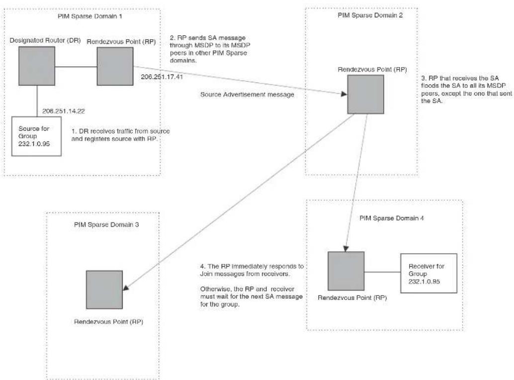
flowchart
graph TD
A["Designated Router (DR)"] -->|206.251.14.22 Source for Group 232.1.0.95| B["Rendezvous Point (RP)"]
B -->|206.251.17.41 Source Advertisement message| C["Rendezvous Point (RP)"]
C --> D["PIM Sparse Domain 2"]
D --> E["PIM Sparse Domain 4"]
E --> F["Rendezvous Point (RP)"]
F --> G["Receiver for Group 232.1.0.95"]
style A fill:#ccc,stroke:#333
style B fill:#ccc,stroke:#333
style C fill:#ccc,stroke:#333
style D fill:#ccc,stroke:#333
style E fill:#ccc,stroke:#333
style F fill:#ccc,stroke:#333
style G fill:#ccc,stroke:#333
In this example, the source for PIM Sparse multicast group 232.0.1.95 is in PIM Sparse domain 1. The source sends a packet for the group to its directly attached DR. The DR sends a Group Advertisement message for the group to the domain's RP. The RP is configured for MSDP, which enables the RP to exchange source information with other PIM Sparse domains by communicating with RPs in other domains that are running MSDP.
The RP sends the source information to each of its peers by sending a Source Active message. The message contains the IP address of the source, the group address to which the source is sending, and the IP address of the RP interface with its peer. By default, the IP address included in the RP address field of the SA message is the IP address of the originating RP, but an SA message can use the IP address of any interface on the originating RP. (The interface is usually a loopback interface.)
In this example, the Source Active message contains the following information:
• Source address: 206.251.14.22
• Group address: 232.1.0.95
• RP address: 206.251.17.41
Figure 93 shows only one peer for the MSDP router (which is also the RP here) in domain 1, so the Source Active message goes to only that peer. When an MSDP router has multiple peers, it sends a Source Active message to each of those peers. Each peer sends the Source Advertisement to its other MSDP peers. The RP that receives the Source Active message also sends a Join message for the group if the RP that received the message has receivers for the group.
Peer Reverse Path Forwarding (RPF) flooding
When the MSDP router (also the RP) in domain 2 receives the Source Active message from its peer in domain 1, the MSDP router in domain 2 forwards the message to all its other peers. The propagation process is sometimes called “peer Reverse Path Forwarding (RPF) flooding”. This term refers to the fact that the MSDP router uses its PIM Sparse RPF tree to send the message to its peers within the tree. In Figure 93, the MSDP router floods the Source Active message it receives from its peer in domain 1 to its other peers, in domains 3 and 4.
Note that the MSDP router in domain 2 does not forward the Source Active back to its peer in domain 1, because that is the peer from which the router received the message. An MSDP router never sends a Source Active message back to the peer that sent it. The peer that sent the message is sometimes called the "RPF peer". The MSDP router uses the unicast routing table for its Exterior Gateway Protocol (EGP) to identify the RPF peer by looking for the route entry that is the next hop toward the source. Often, the EGP protocol is Border Gateway Protocol (BGP) version 4.
NOTE
MSDP depends on BGP and MBGP for interdomain operations.
The MSDP routers in domains 3 and 4 also forward the Source Active message to all their peers except the ones that sent them the message. Figure 93 does not show additional peers.
Source active caching
When an MSDP router that is also an RP receives a Source Active message, the RP checks its PIM Sparse multicast group table for receivers for the group. If the DR has a receiver for the group being advertised in the Source Active message, the DR sends a Join message for that receiver back to the DR in the domain from which the Source Active message came. Usually, the DR is also the MSDP router that sent the Source Active message.
In Figure 93, if the MSDP router and RP in domain 4 has a table entry for the receiver, the RP sends a Join message on behalf of the receiver back through the RPF tree to the RP for the source, in this case the RP in domain 1.
Some MSDP routers that are also RPs can cache Source Active messages. If the RP is not caching Source Active messages, the RP does not send a Join message unless it already has a receiver that wants to join the group. Otherwise, the RP does not send a Join message and does not remember the information in the Source Active message after forwarding it. If the RP receives a request from a receiver for the group, the RP and receiver must wait for the next Source Active message for that group before the RP can send a Join message for the receiver.
However, if Source Active caching is enabled on the MSDP and RP router, the RP caches the Source Active messages it receives. In this case, even if the RP does not have a receiver for a group when the RP receives the Source Active message for the group, the RP can immediately send a Join for a new receiver that wants to join the group, without waiting for the next Source Active message from the RP in the source's domain.
The size of the cache used to store MSDP Source Active messages is 8K
Configuring MSDP
To configure MSDP on a BigIron RX, perform the following tasks:
- Enable MSDP
- Configure the MSDP peers
NOTE
The PIM Sparse Rendezvous Point (RP) is also an MSDP peer.
Routers that run MSDP must also run BGP. Also, the source address used by the MSDP router must be the same source address used by BGP.
Enabling MSDP
NOTE
You must save the configuration and reload the software to place the change into effect.
To enable MSDP, enter the following commands.
BigIron RX(config)# router msdp
BigIron RX(config-msdp-router)# write memory
Syntax: [no] router msdp
Configuring MSDP peers
To configure an MSDP peer, enter a command such as the following at the MSDP configuration level.
BigIron RX(config-msdp-router)# msdp-peer 205.216.162.1
Syntax: [no]msdp-peer
The
The connect-source loopback
NOTE
It is strongly recommended that you use the connect-source loopback
The commands in the following example add an MSDP neighbor and specify a loopback interface as the source interface for sessions with the neighbor. By default, the BigIron RX uses the subnet address configured on the physical interface where you configure the neighbor as the source address for sessions with the neighbor.
BigIron RX(config)# interface loopback 1
BigIron RX(config-lbif-1)# ip address 9.9.9.9/32
BigIron RX(config-lbif-1)# exit
BigIron RX(config)# router msdp
BigIron RX(config-msdp-router)# msdp-peer 2.2.2.99 connect-source loopback 1
Designating an interface's IP address as the RP's IP address
When an RP receives a Source Active message, it checks its PIM Sparse multicast group table for receivers for the group. If it finds a receiver, the RP sends a Join message for that receiver back to the RP that originated the Source Active message. The originator RP is identified by its RP address.
By default, the IP address included in the RP address field of the SA message is the IP address of the originating RP, but an SA message can use the IP address of any interface on the originating RP. (The interface is usually a loopback interface.)
To designate an interface's IP address to be the IP address of the RP, enter commands such as the following.
BigIron RX(config)# interface loopback 2
BigIron RX(config-lbif-2)# ip address 2.2.1.99/32
BigIron RX(config)# router msdp
BigIron RX(config-msdp-router)# originator-id loopback 2
BigIron RX(config-msdp-router)# exit
Syntax: [no] originator-id
The originator-id parameter instructs MSDP to use the specified address as the IP address of the RP in an SA message. This address must be the address of the interface used to connect the RP to the source. There are no default originator-ids.
The
The
Filtering MSDP source-group pairs
You can filter individual source-group pairs in MSDP Source-Active messages. The filter only bars the DUT from local processing of the MSDP SAs.
- sa-filter in – Filters source-group pairs received in Source-Active messages from an MSDP neighbor.
- sa-filter originate – Filters source-group pairs in Source-Active messages in advertisements to an MSDP neighbor.
Filtering incoming source-active messages
The following example configures filters for incoming Source-Active messages from three MSDP neighbors:
- For peer 2.2.2.99, all source-group pairs in Source-Active messages from the neighbor are filtered out (ignored) from local processing of the MSDP SAs.
- For peer 2.2.2.97, all source-group pairs except those with 10.x.x.x as the source are permitted.
- For peer 2.2.2.96, all source-group pairs except those associated with RP 2.2.42.3 are permitted.
The following commands configure an IP address on port 3/1. This is the port on which the MSDP neighbors will be configured.
BigIron RX(config)# interface ethernet 3/1
BigIron RX(config-if-e1000-3/1)# ip address 2.2.2.98/24
BigIron RX(config-if-e1000-3/1)# exit
The following commands configure a loopback interface. The BigIron RX will use this interface as the source address for communicating with the MSDP neighbors.
BigIron RX(config)# interface loopback 1
BigIron RX(config-lbif-1)# ip address 9.9.9.8/32
BigIron RX(config-lbif-1)# exit
The following commands configure extended ACLs. The ACLs will be used in route maps, which will be used by the Source-Active filters.
BigIron RX(config)# access-list 124 permit ip 10.0.0.0 0.255.255.255 any
BigIron RX(config)# access-list 124 permit ip host 2.2.2.2 any
BigIron RX(config)# access-list 125 permit ip any any
The following commands configure the route maps.
BigIron RX(config)# route-map msdp_map deny 1
BigIron RX(config-routemap msdp_map)# match ip address 123
BigIron RX(config-routemap msdp_map)# exit
BigIron RX(config)# route-map msdp2_map permit 1
BigIron RX(config-routemap msdp2_map)# match ip address 125
BigIron RX(config-routemap msdp2_map)# exit
BigIron RX(config)# route-map msdp2_rp_map deny 1
BigIron RX(config-routemap msdp2_rp_map)# match ip route-source 124
BigIron RX(config-routemap msdp2_rp_map)# exit
The following commands enable MSDP and configure the MSDP neighbors on port 3/1.
BigIron RX(config)# router msdp
BigIron RX(config-msdp-router)# msdp-peer 2.2.2.99 connect-source loopback 1
BigIron RX(config-msdp-router)# msdp-peer 2.2.2.97 connect-source loopback 1
BigIron RX(config-msdp-router)# msdp-peer 2.2.2.96 connect-source loopback 1
BigIron RX(config-msdp-router)# exit
The following commands configure the Source-Active filters.
BigIron RX(config)# router msdp
BigIron RX(config-msdp-router)# sa-filter in 2.2.2.99
BigIron RX(config-msdp-router)# sa-filter in 2.2.2.97 route-map msdp_map
BigIron RX(config-msdp-router)# sa-filter in 2.2.2.96 route-map msdp2_map
rp-route-map msdp2_rp_map
The sa-filter commands configure the following filters:
- sa-filter in 2.2.2.99 - This command filters the DUT from local processing and all source-group pairs received from neighbor 2.2.2.99.
NOTE
The default action is to deny all source-group pairs from the specified neighbor. If you want to permit some pairs, use route maps.
- sa-filter in 2.2.2.97 route-map msdp_map - This command ignores source-group pairs received from neighbor 2.2.2.97 if the pairs have source address 10.x.x.x and any group address.
- sa-filter in 2.2.2.96 route-map msdp2_map rp-route-map msdp2_rp_map - This command accepts all source-group pairs except those associated with RP 2.2.42.3.
Syntax: [no] sa-filter in
The
The route-map
The rp-route-map
NOTE
The default filter action is deny. If you want to permit some source-group pairs, use a route map. A permit action in the route map allows the BigIron RX to receive the matching source-group pairs. A deny action in the route map drops the matching source-group pairs.
Filtering advertised source-active messages
The following example configures the BigIron RX to advertise all source-group pairs except the ones that have source address 10.x.x.x.
The following commands configure an IP address on port 3/1. This is the port on which the MSDP neighbors will be configured.
BigIron RX(config)# interface ethernet 3/1
BigIron RX(config-if-e1000-e1000-3/1)# ip address 2.2.2.98/24
BigIron RX(config-if-e1000-3/1)# exit
The following commands configure a loopback interface. The BigIron RX will use this interface as the source address for communicating with the MSDP neighbors.
BigIron RX(config)# interface loopback 1
BigIron RX(config-lbif-1)# ip address 9.9.9.8/32
BigIron RX(config-lbif-1)# exit
The following command configures an extended ACL to specify the source and group addresses you want to filter.
BigIron RX(config)# access-list 123 permit ip 10.0.0.0 0.255.255.255 any
The following commands configure a route map. The map matches on source address 10.x.x.x and any group address. Since the action is deny, the Source-Active filter that uses this route map will remove the source-group pairs that match this route map from the Source-Active messages to the neighbor.
BigIron RX(config)# route-map msdp_map deny 1
BigIron RX(config-routemap msdp_map)# match ip address 123
BigIron RX(config-routemap msdp_map)# exit
The following commands enable MSDP and configure MSDP neighbors on port 3/1.
BigIron RX(config)# router msdp
BigIron RX(config-msdp-router)# msdp-peer 2.2.2.99 connect-source loopback 1
BigIron RX(config-msdp-router)# msdp-peer 2.2.2.97 connect-source loopback 1
BigIron RX(config-if-3/1)# exit
The following commands configure the Source-Active filter.
BigIron RX(config)# router msdp
BigIron RX(config-msdp-router)# sa-filter originate route-map msdp_map
This filter removes source-group pairs that match route map msdp_map from Source-Active messages before sending them to MSDP neighbors.
Syntax: [no] sa-filter originate [route-map
The route-map
NOTE
The default filter action is deny. If you want to permit some source-group pairs, use a route map. A permit action in the route map allows the BigIron RX to receive the matching source-group pairs. A deny action in the route map drops the matching source-group pairs.
Displaying the differences before and after the source active filters are applied
This is an example of the Source Actives in the MSDP cache that will be displayed before the filter is applied.
BigIron RX #show ip msdp sa
Total 50 entries
| Index | SourceAddr | GroupAddr | Age |
| 1 | (117.1.0.60, 224.200.1.40), RP:2.2.2.2, Age:0 | ||
| 2 | (117.1.0.33, 224.200.1.13), RP:2.2.2.2, Age:0 | ||
| 3 | (117.1.0.47, 224.200.1.27), RP:2.2.2.2, Age:0 | ||
| 4 | (117.1.0.20, 224.200.1.0), RP:2.2.2.2, Age:0 | ||
| 5 | (117.1.0.61, 224.200.1.41), RP:2.2.2.2, Age:0 | ||
| 6 | (117.1.0.34, 224.200.1.14), RP:2.2.2.2, Age:0 | ||
| 7 | (117.1.0.48, 224.200.1.28), RP:2.2.2.2, Age:0 | ||
| 8 | (117.1.0.21, 224.200.1.1), RP:2.2.2.2, Age:0 | ||
| 9 | (117.1.0.62, 224.200.1.42), RP:2.2.2.2, Age:0 | ||
| 10 | (117.1.0.35, 224.200.1.15), RP:2.2.2.2, Age:0 | ||
| 11 | (117.1.0.49, 224.200.1.29), RP:2.2.2.2, Age:0 | ||
| 12 | (117.1.0.22, 224.200.1.2), RP:2.2.2.2, Age:0 | ||
| 13 | (117.1.0.63, 224.200.1.43), RP:2.2.2.2, Age:0 | ||
| 14 | (117.1.0.36, 224.200.1.16), RP:2.2.2.2, Age:0 | ||
| 15 | (117.1.0.50, 224.200.1.30), RP:2.2.2.2, Age:0 | ||
| 16 | (117.1.0.23, 224.200.1.3), RP:2.2.2.2, Age:0 | ||
| 17 | (117.1.0.64, 224.200.1.44), RP:2.2.2.2, Age:0 | ||
| 18 | (117.1.0.37, 224.200.1.17), RP:2.2.2.2, Age:0 | ||
| 19 | (117.1.0.51, 224.200.1.31), RP:2.2.2.2, Age:0 | ||
| 20 | (117.1.0.24, 224.200.1.4), RP:2.2.2.2, Age:0 | ||
| 21 | (117.1.0.65, 224.200.1.45), RP:2.2.2.2, Age:0 | ||
| 22 | (117.1.0.38, 224.200.1.18), RP:2.2.2.2, Age:0 | ||
| 23 | (117.1.0.52, 224.200.1.32), RP:2.2.2.2, Age:0 | ||
| 24 | (117.1.0.25, 224.200.1.5), RP:2.2.2.2, Age:0 | ||
| 25 | (117.1.0.66, 224.200.1.46), RP:2.2.2.2, Age:0 | ||
| 26 | (117.1.0.39, 224.200.1.19), RP:2.2.2.2, Age:0 | ||
| 27 | (117.1.0.53, 224.200.1.33), RP:2.2.2.2, Age:0 | ||
| 28 | (117.1.0.26, 224.200.1.6), RP:2.2.2.2, Age:0 | ||
| 29 | (117.1.0.67, 224.200.1.47), RP:2.2.2.2, Age:0 | ||
| 30 | (117.1.0.40, 224.200.1.20), RP:2.2.2.2, Age:0 | ||
| 31 | (117.1.0.54, 224.200.1.34), RP:2.2.2.2, Age:0 | ||
| 32 | (117.1.0.27, 224.200.1.7), RP:2.2.2.2, Age:0 | ||
| 33 | (117.1.0.68, 224.200.1.48), RP:2.2.2.2, Age:0 | ||
| 34 | (117.1.0.41, 224.200.1.21), RP:2.2.2.2, Age:0 | ||
| 35 | (117.1.0.55, 224.200.1.35), RP:2.2.2.2, Age:0 | ||
| 36 | (117.1.0.28, 224.200.1.8), RP:2.2.2.2, Age:0 | ||
| 37 | (117.1.0.69, 224.200.1.49), RP:2.2.2.2, Age:0 | ||
| 38 | (117.1.0.42, 224.200.1.22), RP:2.2.2.2, Age:0 | ||
| 39 | (117.1.0.56, 224.200.1.36), RP:2.2.2.2, Age:0 | ||
| 40 | (117.1.0.29, 224.200.1.9), RP:2.2.2.2, Age:0 | ||
| 41 | (117.1.0.43, 224.200.1.23), RP:2.2.2.2, Age:0 | ||
| 42 | (117.1.0.57, 224.200.1.37), RP:2.2.2.2, Age:0 | ||
| 43 | (117.1.0.30, 224.200.1.10), RP:2.2.2.2, Age:0 | ||
| 44 | (117.1.0.44, 224.200.1.24), RP:2.2.2.2, Age:0 | ||
| 45 | (117.1.0.58, 224.200.1.38), RP:2.2.2.2, Age:0 | ||
| 46 | (117.1.0.31, 224.200.1.11), RP:2.2.2.2, Age:0 | ||
| 47 | (117.1.0.45, 224.200.1.25), RP:2.2.2.2, Age:0 | ||
| 48 | (117.1.0.59, 224.200.1.39), RP:2.2.2.2, Age:0 | ||
| 49 | (117.1.0.32, 224.200.1.12), RP:2.2.2.2, Age:0 | ||
| 50 | (117.1.0.46, 224.200.1.26), RP:2.2.2.2, Age:0 | ||
| Total number of SA Cache entries50 | |||
Syntax: show ip msdp sa
This is an example of the Source Actives in the MSDP cache that will be displayed after the filter is applied.
BigIron RX #show ip msdp sa
Total 6 entries
Index SourceAddr GroupAddr Age
| 1 | (117.1.0.69, 224.200.1.49), RP:2.2.2.2, Age:0 |
| 2 | (117.1.0.64, 224.200.1.44), RP:2.2.2.2, Age:0 |
| 3 | (117.1.0.65, 224.200.1.45), RP:2.2.2.2, Age:0 |
| 4 | (117.1.0.66, 224.200.1.46), RP:2.2.2.2, Age:0 |
| 5 | (117.1.0.67, 224.200.1.47), RP:2.2.2.2, Age:0 |
| 6 | (117.1.0.68, 224.200.1.48), RP:2.2.2.2, Age:0 |
Total number of SA Cache entries 6
Syntax: show ip msdp sa
Syntax: show ip msdp sa-cache
This display shows the following information.
TABLE 104 MSDP source active cache
| This field... Displays... |
| Total Entry The total number of entries the cache can hold. |
| Used The number of entries the cache currently contains. |
| Free The number of additional entries for which the cache has room. |
Index The cache entry number.
TABLE 104 MSDP source active cache (Continued)
| This field... Displays... |
| SourceAddr The IP address of the multicast source. |
| GroupAddr The IP multicast group to which the source is sending information. |
| RP The RP through which receivers can access the group traffic from the source |
| Age The number of seconds the entry has been in the cache |
Configuring MSDP mesh groups
A PIM Sparse domain can have several RPs that are connected to each other to form an MSDP mesh group. To qualify as a mesh group, the RPs have to be fully meshed; that is, each RP must be connected to all peer RPs in a domain. (Refer to Figure 94.)
A mesh group reduces the forwarding of SA messages within a domain. Instead of having every RP in a domain forward SA messages to all the RPs within that domain, only one RP forwards the SA message. Since an MSDP mesh group is fully meshed, peers do not forward SA messages received in a domain from one member to every member of the group. The RP that originated the SA or the first RP in a domain that receives the SA message is the only one that can forward the message to the members of a mesh group. If a mesh-group member receives a SA message from a MSDP peer that is not a member of the mesh-group, and the SA message passes the RPF check, then the member forwards the SA message to all members of the mesh-group. An RP can forward an SA message to any MSRP router as long as that peer is farther away from the originating RP than the current MSRP router.
Figure 94 shows an example of an MSDP mesh group. In a PIM-SM mesh group the RPs are configured to be peers of each other. They can also be peers of RPs in other domains.
FIGURE 94 Example of MSDP mesh group

flowchart
graph TD
A["Designated Router (DR)"] -->|206.251.14.22| B["Source for Group 232.1.0.95"]
B --> C["1. DR receives traffic from source and registers source with RP"]
C --> D["RP 206.251.20.31"]
D --> E["PIM Sparse Domain 4"]
D --> F["PIM Sparse Domain 3"]
D --> G["PIM Sparse Domain 2"]
E --> H["RP 206.251.21.31"]
F --> I["RP 206.251.19.31"]
G --> J["RP 206.251.18.31"]
H --> K["RP 206.251.21.31"]
I --> L["RP 206.251.19.31"]
J --> M["RP 206.251.18.31"]
K --> N["RP 206.251.20.31"]
L --> O["RP 206.251.18.31"]
M --> P["RP 206.251.21.31"]
N --> Q["RP 206.251.18.31"]
O --> R["RP 206.251.20.31"]
P --> S["RP 206.251.19.31"]
Q --> T["RP 206.251.21.31"]
R --> U["RP 206.251.18.31"]
S --> V["RP 206.251.20.31"]
T --> W["RP 206.251.18.31"]
U --> X["RP 206.251.21.31"]
V --> Y["RP 206.251.18.31"]
W --> Z["RP 206.251.20.31"]
X --> AA["RP 206.251.18.31"]
Y --> AB["RP 206.251.21.31"]
Z --> AC["RP 206.251.18.31"]
AA --> AD["RP 206.251.20.31"]
AB --> AE["RP 206.251.18.31"]
PIM Sparse Domain 1 in Figure 94 contains a mesh group with four RPs. When the first RP, for example, RP 206.251.21.41 (which is also the originating RP), receives an SA message from the source, it sends the SA message to its peers within the domain, but the peers do not send the message back to the originator RP or to each other. The RPs then send the SA message to their peers in other domains. The process continues until all RPs within the network receive the SA message. RPs send join and prune messages to appropriate points on the multicast tree towards the originating RP.
Configuring MSDP mesh group
To configure an MSDP mesh group, enter commands such as the following on each device that will be included in the mesh group.
| BigIron RX(config)# router msdp |
| BigIron RX(config-msdp-router)# msdp-peer 163.5.34.10 connect-source loopback 2 |
| BigIron RX(config-msdp-router)# msdp-peer 206.251.21.31 connect-source loopback 2 |
| BigIron RX(config-msdp-router)# msdp-peer 206.251.17.31 connect-source loopback 2 |
| BigIron RX(config-msdp-router)# msdp-peer 206.251.13.31 connect-source loopback 2 |
| BigIron RX(config-msdp-router)# mesh-group GroupA 206.251.21.31 |
| BigIron RX(config-msdp-router)# mesh-group GroupA 206.251.17.31 |
| BigIron RX(config-msdp-router)# mesh-group GroupA 206.251.13.31 |
| BigIron RX(config-msdp-router)# exit |
Syntax: [no] mesh-group
The sample configuration above reflects the configuration in Figure 94. On RP 206.251.21.31 you specify its peers within the same domain (206.251.21.31, 206.251.17.31, and 206.251.13.31).
You first configure the MSDP peers using the msdp-peer command to assign their IP addresses and the loopback interfaces. This information will be used as the source for sessions with the neighbor.
Next, place the MSDP peers within a domain into a mesh group. Use the mesh-group command. There are no default mesh groups.
The group-name parameter identifies the group. Enter up to 31 characters for group-name. You can have up to 4 mesh groups within a multicast network. Each mesh group can include up to 32 peers.
The peer-address parameter specifies the IP address of the MSDP peer that is being placed in the group.
NOTE
On each of the device that will be part of the mesh-group, there must be a mesh-group definition for all the peers in the mesh-group.
Up to 32 MSDP peers can be configured per mesh group.
In Figure 95, devices A, B, C, and D are in Mesh Group 1234. The example configuration following the figure shows how the devices are configured to be part of the MSDP mesh group. The example also shows the features that need to be enabled for the MSDP mesh group to work.
FIGURE 95 MSDP mesh group 1234
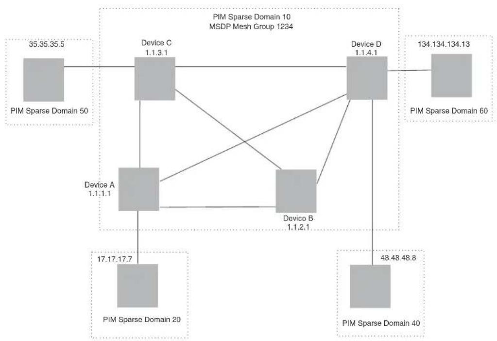
flowchart
graph TD
A["PIM Sparse Domain 50"] --> B["Device C 1.1.3.1"]
B --> C["Device A 1.1.1.1"]
C --> D["PIM Sparse Domain 20"]
B --> E["Device B 1.1.2.1"]
E --> F["PIM Sparse Domain 40"]
B --> G["Device D 1.1.4.1"]
G --> H["134.134.134.13"]
G --> I["PIM Sparse Domain 60"]
style A fill:#f9f,stroke:#333
style B fill:#ccf,stroke:#333
style C fill:#cfc,stroke:#333
style D fill:#fcc,stroke:#333
style E fill:#cff,stroke:#333
style F fill:#ffc,stroke:#333
style G fill:#cfc,stroke:#333
style H fill:#fcc,stroke:#333
Configuration for Device A
The following set of commands configure the MSDP peers of Device A (1.1.1.1) that are inside and outside MSDP mesh group 1234. Device A's peers inside the mesh group 1234 are 1.1.2.1, 1.1.3.1, and 1.1.4.1. Device 17.17.17.7 is a peer of Device A, but is outside mesh group 1234. Multicast is enabled on Device A's interfaces. PIM and BGP are also enabled.
BigIron RX(config)# router pim
BigIron RX(config)# router msdp
BigIron RX(config-msdp-router)# msdp-peer 1.1.3.1 connect-source 1.1.4.1
BigIron RX(config-msdp-router)# msdp-peer 1.1.4.1 connect-source 1.1.4.1
BigIron RX(config-msdp-router)# msdp-peer 1.1.2.1 connect-source 1.1.2.1
BigIron RX(config-msdp-router)# msdp-peer 17.17.17.7
BigIron RX(config-msdp-router)# mesh-group 1234 1.1.4.1
BigIron RX(config-msdp-router)# mesh-group 1234 1.1.3.1
BigIron RX(config-msdp-router)# mesh-group 1234 1.1.2.1
BigIron RX(config-msdp-router)# exit
BigIron RX(config)# interface loopback 1
BigIron RX(config-lbif-1)# ip address 1.1.1.1 255.255.255.0
BigIron RX(config-lbif-1)# ip pim-sparse
BigIron RX(config-lbif-1)# exit
BigIron RX(config)# interface ethernet 1/1
BigIron RX(config-if-1/1)# ip address 14.14.14.1 255.255.255.0
BigIron RX(config-if-1/1)# ip pim-sparse
BigIron RX(config-if-1/1)# exit
BigIron RX(config)# interface ethernet 2/1
BigIron RX(config-if-2/1)# ip address 12.12.12.1 255.255.255.0
BigIron RX(config-if-2/1)# ip pim-sparse
BigIron RX(config-if-2/1)# exit
BigIron RX(config)# interface ethernet 2/20
BigIron RX(config-if-2/20)# ip address 159.159.159.1 255.255.255.0
BigIron RX(config-if-2/20)# ip pim-sparse
BigIron RX(config-if-2/20)# exit
BigIron RX(config)# interface ethernet 4/1
BigIron RX(config-if-4/1)# ip address 31.31.31.1 255.255.255.0
BigIron RX(config-if-4/1)# ip pim-sparse
BigIron RX(config-if-4/1)# exit
BigIron RX(config)# interface ethernet 4/8
BigIron RX(config-if-4/8)# ip address 17.17.17.1 255.255.255.0
BigIron RX(config-if-4/8)# ip pim-sparse
BigIron RX(config-if-4/8)# ip pim border
BigIron RX(config-if-4/8)# exit
BigIron RX(config)# router pim
BigIron RX(config-router-pim)# bsr-candidate loopback 1 1 31
BigIron RX(config-router-pim)# rp-candidate loopback 1
BigIron RX(config-router-pim)# exit
BigIron RX(config)# router bgp
BigIron RX(config-bgp-router)# local-as 111
BigIron RX(config-bgp-router)# neighbor 31.31.31.3 remote-as 333
BigIron RX(config-bgp-router)# neighbor 31.31.31.3 next-hop-self
BigIron RX(config-bgp-router)# neighbor 12.12.12.2 remote-as 222
BigIron RX(config-bgp-router)# neighbor 12.12.12.2 next-hop-self
BigIron RX(config-bgp-router)# neighbor 14.14.14.4 remote-as 444
BigIron RX(config-bgp-router)# neighbor 14.14.14.4 next-hop-self
BigIron RX(config-bgp-router)# neighbor 17.17.17.7 remote-as 777
BigIron RX(config-bgp-router)# neighbor 17.17.17.7 next-hop-self
BigIron RX(config-bgp-router)# redistribute connected
BigIron RX(config-bgp-router)# write memory
Configuration for Device B
The following set of commands configure the MSDP peers of Device B. All Device B's peers (1.1.1.1, 1.1.3.1, and 1.1.4.1) are in the MSDP mesh group 1234. Multicast is enabled on Device B's interfaces. PIM and BGP are also enabled.
BigIron RX(config)# router pim
BigIron RX(config)# router msdp
BigIron RX(config-msdp-router)# msdp-peer 1.1.3.1 connect-source loopback 1
BigIron RX(config-msdp-router)# msdp-peer 1.1.1.1 connect-source loopback 1
BigIron RX(config-msdp-router)# msdp-peer 1.1.4.1 connect-source loopback 1
BigIron RX(config-msdp-router)# mesh-group 1234 1.1.1.1
BigIron RX(config-msdp-router)# mesh-group 1234 1.1.3.1
BigIron RX(config-msdp-router)# mesh-group 1234 1.1.4.1
BigIron RX(config-msdp-router)# exit
BigIron RX(config)# interface loopback 1
BigIron RX(config-lbif-1)# ip address 1.1.2.1 255.255.255.0
BigIron RX(config-lbif-1)# ip pim-sparse
BigIron RX(config-lbif-1)# exit
BigIron RX(config)# interface ethernet 1/1
BigIron RX(config-if-1/1)# ip address 12.12.12.2 255.255.255.0
BigIron RX(config-if-1/1)# ip pim-sparse
BigIron RX(config-if-1/1)# exit
BigIron RX(config)# interface ethernet 1/12
BigIron RX(config-if-1/12)# ip address 165.165.165.1 255.255.255.0
BigIron RX(config-if-1/12)# ip pim-sparse
BigIron RX(config-if-1/12)# exit
BigIron RX(config)# interface ethernet 1/24
BigIron RX(config-if-1/24)# ip address 168.72.2.2 255.255.255.0
BigIron RX(config-if-1/24)# exit
BigIron RX(config)# interface ethernet 1/25
BigIron RX(config-if-1/25)# ip address 24.24.24.2 255.255.255.0
BigIron RX(config-if-1/25)# ip pim-sparse
BigIron RX(config-if-1/24)# exit
BigIron RX(config)# interface ethernet 8/1
BigIron RX(config-if-8/1)# ip address 32.32.32.2 255.255.255.0
BigIron RX(config-if-8/1)# ip pim-sparse
BigIron RX(config-if-1/24)# exit
BigIron RX(config)# router pim
BigIron RX(config-router-pim)# bsr-candidate loopback 1 2 32
BigIron RX(config-router-pim)# rp-candidate loopback 1
BigIron RX(config-router-pim)# exit
BigIron RX(config)# router bgp
BigIron RX(config-router-bgp)# local-as 222
BigIron RX(config-router-bgp)# neighbor 32.32.32.3 remote-as 333
BigIron RX(config-router-bgp)# neighbor 32.32.32.3 next-hop-self
BigIron RX(config-router-bgp)# neighbor 24.24.24.4 remote-as 444
BigIron RX(config-router-bgp)# neighbor 24.24.24.4 next-hop-self
BigIron RX(config-router-bgp)# neighbor 12.12.12.1 remote-as 111
BigIron RX(config-router-bgp)# neighbor 12.12.12.1 next-hop-self
BigIron RX(config-router-bgp)# redistribute connected
BigIron RX(config-router-bgp)# write memory
Configuration for Device C
The following set of commands configure the MSDP peers of Device C (1.1.3.1) that are inside and outside MSDP mesh group 1234. Device C's peers inside the mesh group 1234 are 1.1.1.1, 1.1.2.1, and 1.1.4.1. Device 35.35.35.5 is a peer of Device C, but is outside mesh group 1234. Multicast is enabled on Device C's interfaces. PIM and BGP are also enabled.
BigIron RX(config)# router pim
BigIron RX(config)# router msdp
BigIron RX(config-msdp-router)# msdp-peer 35.35.35.5
BigIron RX(config-msdp-router)# msdp-peer 1.1.2.1 connect-source loopback 1
BigIron RX(config-msdp-router)# msdp-peer 1.1.4.1 connect-source loopback 1
BigIron RX(config-msdp-router)# msdp-peer 1.1.1.1 connect-source loopback 1
BigIron RX(config-msdp-router)# mesh-group 1234 1.1.2.1
BigIron RX(config-msdp-router)# mesh-group 1234 1.1.1.1
BigIron RX(config-msdp-router)# mesh-group 1234 1.1.4.1
BigIron RX(config-msdp-router)# exit
BigIron RX(config)# interface loopback 1
BigIron RX(config-lbif-1)# ip address 1.1.3.1 255.255.255.0
BigIron RX(config-lbif-1)# ip pim-sparse
BigIron RX(config-lbif-1)# exit
BigIron RX(config)# interface ethernet 3/1
BigIron RX(config-if-3/1)# ip address 32.32.32.3 255.255.255.0
BigIron RX(config-if-3/1)# ip pim-sparse
BigIron RX(config-if-3/1)# exit
BigIron RX(config)# interface ethernet 10/1
BigIron RX(config-if-10/1)# ip address 31.31.31.3 255.255.255.0
BigIron RX(config-if-10/1)# ip pim-sparse
BigIron RX(config-if-10/1)# exit
BigIron RX(config)# interface ethernet 10/8
BigIron RX(config-if-10/8)# ip address 35.35.35.3 255.255.255.0
BigIron RX(config-if-10/8)# ip pim-sparse
BigIron RX(config-if-10/8)# ip pim border
BigIron RX(config-if-10/8)# exit
BigIron RX(config)# interface ethernet 12/2
BigIron RX(config-if-12/1)# ip address 34.34.34.3 255.255.255.0
BigIron RX(config-if-12/1)# ip pim-sparse
BigIron RX(config-if-12/1)# exit
BigIron RX(config)# interface ethernet 14/4
BigIron RX(config-if-14/4)# ip address 154.154.154.1 255.255.255.0
BigIron RX(config-if-12/1)# ip pim-sparse
BigIron RX(config-if-12/1)# exit
BigIron RX(config)# router pim
BigIron RX(config-router-pim)# bsr-candidate loopback 1 1 3
BigIron RX(config-router-pim)# rp-candidate loopback 1
BigIron RX(config-router-pim)# exit
BigIron RX(config)# router bgp
BigIron RX(config-router-bsr)# local-as 333
BigIron RX(config-router-bsr)# neighbor 35.35.35.5 remote-as 555
BigIron RX(config-router-bsr)# neighbor 35.35.35.5 next-hop-self
BigIron RX(config-router-bsr)# neighbor 32.32.32.2 remote-as 222
BigIron RX(config-router-bsr)# neighbor 32.32.32.2 next-hop-self
BigIron RX(config-router-bsr)# neighbor 34.34.34.4 remote-as 444
BigIron RX(config-router-bsr)# neighbor 34.34.34.4 next-hop-self
BigIron RX(config-router-bsr)# neighbor 31.31.31.1 remote-as 111
BigIron RX(config-router-bsr)# neighbor 31.31.31.1 next-hop-self
BigIron RX(config-router-bsr)# redistribute connected
BigIron RX(config-router-bsr)# write memory
Configuration for Device D
The following set of commands configure the MSDP peers of Device D (1.1.4.1) that are inside and outside MSDP mesh group 1234. Device D's peers inside the mesh group 1234 are 1.1.1.1, 1.1.2.1, and 1.1.3.1. Device 48.48.48.8 and 134.134.134.13 are also peers of Device D, but are outside mesh group 1234. Multicast is enabled on Device D's interfaces. PIM and BGP are also enabled.
BigIron RX(config)# router pim
BigIron RX(config)# router msdp
BigIron RX(config-msdp-router)# msdp-peer 1.1.3.1 connect-source loopback 1
BigIron RX(config-msdp-router)# msdp-peer 1.1.1.1 connect-source loopback 1
BigIron RX(config-msdp-router)# msdp-peer 1.1.2.1 connect-source loopback 1
BigIron RX(config-msdp-router)# msdp-peer 48.48.48.8
BigIron RX(config-msdp-router)# msdp-peer 134.134.134.13
BigIron RX(config-msdp-router)# mesh-group 1234 1.1.1.1
BigIron RX(config-msdp-router)# mesh-group 1234 1.1.3.1
BigIron RX(config-msdp-router)# mesh-group 1234 1.1.2.1
BigIron RX(config-msdp-router)# exit
BigIron RX(config)# interface loopback 1
BigIron RX(config-lbif-)# ip address 1.1.4.1 255.255.255.0
BigIron RX(config-lbif-)# ip pim-sparse
BigIron RX(config-lbif-)# exit
BigIron RX(config)# interface ethernet 1/1
BigIron RX(config-if-)# ip address 24.24.24.4 255.255.255.0
BigIron RX(config-if-)# ip pim-sparse
BigIron RX(config-if-)# exit
BigIron RX(config)# interface ethernet 2/6
BigIron RX(config-if-)# ip address 156.156.156.1 255.255.255.0
BigIron RX(config-if-)# ip pim-sparse
BigIron RX(config-if-)# exit
BigIron RX(config)# interface ethernet 5/1
BigIron RX(config-if-)# ip address 34.34.34.4 255.255.255.0
BigIron RX(config-if-)# ip pim-sparse
BigIron RX(config-if-)# exit
BigIron RX(config)# interface ethernet 7/1
BigIron RX(config-if-)# ip address 14.14.14.4 255.255.255.0
BigIron RX(config-if-)# ip pim-sparse
BigIron RX(config-if-)# exit
BigIron RX(config)# interface ethernet 7/7
BigIron RX(config-if-)# ip address 48.48.48.4 255.255.255.0
BigIron RX(config-if-)# ip pim-sparse
BigIron RX(config-if-)# ip pim border
BigIron RX(config-if-)# exit
BigIron RX(config)# interface ethernet 7/8
BigIron RX(config-if-)# ip address 134.134.134.4 255.255.255.0
BigIron RX(config-if-)# ip pim-sparse
BigIron RX(config-if-)# ip pim border
BigIron RX(config-if-)# exit
BigIron RX(config)# router pim
BigIron RX(config-router-pim)# bsr-candidate loopback 1 14 34
BigIron RX(config-router-pim)# rp-candidate loopback 1
BigIron RX(config-router-pim)# exit
BigIron RX(config)# router bgp
BigIron RX(config-router-bsr)# local-as 444
BigIron RX(config-router-bsr)# neighbor 34.34.34.3 remote-as 333
BigIron RX(config-router-bsr)# neighbor 34.34.34.3 next-hop-self
BigIron RX(config-router-bsr)# neighbor 14.14.14.1 remote-as 111
BigIron RX(config-router-bsr)# neighbor 14.14.14.1 next-hop-self
BigIron RX(config-router-bsr)# neighbor 24.24.24.2 remote-as 222
BigIron RX(config-router-bsr)# neighbor 24.24.24.2 next-hop-self
BigIron RX(config-router-bsr)# neighbor 48.48.48.8 remote-as 888
BigIron RX(config-router-bsr)# neighbor 48.48.48.8 next-hop-self
BigIron RX(config-router-bsr)# neighbor 134.134.134.13 remote-as 1313
BigIron RX(config-router-bsr)# neighbor 134.134.134.13 next-hop-self
BigIron RX(config-router-bsr)# redistribute connected
BigIron RX(config-router-bsr)# write memory
Displaying MSDP information
You can display the following MSDP information:
- Summary information – the IP addresses of the peers, the state of the BigIron RX's MSDP session with each peer, and statistics for Keepalive, Source Active, and Notification messages sent to and received from each of the peers.
- Peer information – the IP address of the peer, along with detailed MSDP and TCP statistics.
- Source Active cache entries – the Source Active messages cached by the BigIron RX.
Displaying summary information
To display summary MSDP information, enter the following command at any level of the CLI.
BigIron RX# show ip msdp summary
MSDP Peer Status Summary
KA: Keepalive SA: Source-Active NOT: Notification
| Peer Address | State | KA | SA | NOT | |||
| In | Out | In | Out | In | Out | ||
| 206.251.17.30 | ESTABLISH | 3 | 3 | 0 | 640 | 0 | 0 |
| 206.251.17.41 | ESTABLISH | 0 | 3 | 651 | 0 | 0 | 0 |
Syntax: show ip msdp summary
This display shows the following information.
TABLE 105 MSDP summary information
| This field... Displays... |
| Peer Address The IP address of the peer's interface with the BigIron RX |
| State The state of the MSDP router's connection with the peer. The state can be one of the following:CONNECTING - The session is in the active open state.ESTABLISHED - The MSDP session is fully up.INACTIVE - The session is idle.LISTENING - The session is in the passive open state. |
| KA In The number of MSDP Keepalive messages the MSDP router has received from the peer |
| KA Out The number of MSDP Keepalive messages the MSDP router has sent to the peer |
| SA In The number of Source Active messages the MSDP router has received from the peer |
| SA Out The number of Source Active messages the MSDP router has sent to the peer |
| NOT In The number of Notification messages the MSDP router has received from the peer |
| NOT Out The number of Notification messages the MSDP router has sent to the peer |
Displaying peer information
To display MSDP peer information, use the following CLI method.
BigIron RX# show ip msdp peer
Total number of MSDP Peers: 2
| IP Address | State | |
| 1 | 206.251.17.30 | ESTABLISHED |
| Keep Alive Time | Hold Time | |
| 60 | 90 |
| Message Sent | Message Received | |
| Keep Alive | 2 | 3 |
| Notifications | 0 | 0 |
| Source-Active | 0 | 640 |
Last Connection Reset Reason: Reason Unknown
Notification Message Error Code Received: Unspecified
Notification Message Error SubCode Received: Not Applicable
Notification Message Error Code Transmitted: Unspecified
Notification Message Error SubCode Transmitted: Not Applicable
TCP Connection state: ESTABLISHED
Local host: 206.251.17.29, Local Port: 8270
Remote host: 206.251.17.30, Remote Port: 639
ISentSeq: 16927 SendNext: 685654 TotUnAck: 0
SendWnd: 16384 TotSent: 668727 ReTrans: 1
IRcvSeq: 45252428 RcvNext: 45252438 RcvWnd: 16384
TotalRcv: 10 RcvQue: 0 SendQue: 0
Syntax: show ip msdp peer
This display shows the following information.
TABLE 106 MSDP peer information
| This field... Displays... | |
| Total number of MSDP peers The number of MSDP peers configured on the BigIron RX | |
| IP Address The IP address of the peer's interface with the BigIron RX | |
| State The state of the MSDP router's connection with the peer. The state canbe one of the following:CONNECTING – The session is in the active open state.ESTABLISHED – The MSDP session is fully up.INACTIVE – The session is idle.LISTENING – The session is in the passive open state. | |
| Keep Alive Time The keep alive time, which specifies how often this MSDP router sendskeep alive messages to the neighbor. The keep alive time is 60 secondsand is not configurable. | |
| Hold Time The hold time, which specifies how many seconds the MSDP router willwait for a KEEPALIVE or UPDATE message from an MSDP neighborbefore deciding that the neighbor is dead. The hold time is 90 secondsand is not configurable. | |
| Keep Alive Message Received The number of Keep Alive messages the MSDP router has received from the peer. | |
| Notifications Sent The number of Notification messages the MSDP router has sent to the peer. | |
| Notifications Received The number of Notification messages the MSDP router has received from the peer. | |
| Source-Active Sent The number of Source Active messages the MSDP router has sent to the peer. | |
| Source-Active Received The number of Source Active messages the MSDP router has received from the peer. | |
| Last Connection Reset Reason The reason the previous session with this neighbor ended. | |
| Notification Message Error Code Received | If the MSDP router receives a NOTIFICATION messages from the neighbor, the message contains an error code corresponding to one of the following errors. Some errors have subcodes that clarify the reason for the error. Where applicable, the subcode messages are listed underneath the error code messages.1 - Message Header Error2 - SA-Request Error3 - SA-Message or SA-Response Error4 - Hold Timer Expired5 - Finite State Machine Error6 - Notification7 - CeaseFor information about these error codes, see section 17 in the Internet draft describing MSDP, “draft-ietf-msdp-spec”. |
| Notification Message Error SubCode Received | See above. |
| Notification Message Error Code Transmitted | The error message corresponding to the error code in the NOTIFICATION message this MSDP router sent to the neighbor. See the description for the Notification Message Error Code Received field for a list of possible codes. |
| Notification Message Error SubCode Transmitted | See above. |
| TCP connection state The state of the connection with the neighbor. The connection can have one of the following states:LISTEN - Waiting for a connection request.SYN-SENT - Waiting for a matching connection request after having sent a connection request.SYN-RECEIVED - Waiting for a confirming connection request acknowledgment after having both received and sent a connection request.ESTABLISHED - Data can be sent and received over the connection. This is the normal operational state of the connection.FIN-WAIT-1 - Waiting for a connection termination request from the remote TCP, or an acknowledgment of the connection termination request previously sent.FIN-WAIT-2 - Waiting for a connection termination request from the remote TCP.CLOSE-WAIT - Waiting for a connection termination request from the local user.CLOSING - Waiting for a connection termination request acknowledgment from the remote TCP.LAST-ACK - Waiting for an acknowledgment of the connection termination request previously sent to the remote TCP (which includes an acknowledgment of its connection termination request).TIME-WAIT - Waiting for enough time to pass to be sure the remote TCP received the acknowledgment of its connection termination request.CLOSED - There is no connection state. | |
| Local host The IP address of the MSDP router's interface with the peer. | |
| Local port The TCP port the MSDP router is using for the BGP4 TCP session with the neighbor. | |
| Remote host The IP address of the neighbor. | |
| Remote port The TCP port number of the peer end of the connection. | |
| ISentSeq The initial send sequence number for the session. | |
| SendNext The next sequence number to be sent. | |
| TotUnAck The number of sequence numbers sent by the MSDP router that have not been acknowledged by the neighbor. | |
| SendWnd The size of the send window. | |
| TotSent The number of sequence numbers sent to the neighbor. | |
| ReTrans The number of sequence numbers that the MSDP router retransmitted because they were not acknowledged. | |
| IRcvSeq The initial receive sequence number for the session. | |
| RcvNext | The next sequence number expected from the neighbor. |
| RcvWnd The size of the receive window. | |
| TotalRcv | The number of sequence numbers received from the neighbor. |
| RcvQue | The number of sequence numbers in the receive queue. |
| SendQue The number of sequence numbers in the send queue. | |
Displaying source active cache information
To display the Source Actives in the MSDP cache, use the following CLI method.
BigIron RX# show ip msdp sa-cache
| Total Entry 4096, Used 1800 Free 2296 | ||
| Index | SourceAddr | GroupAddr Age |
| 1 | (100.100.1.254, 232.1.0.95), RP:206.251.17.41, Age:0 | |
| 2 | (100.100.1.254, 237.1.0.98), RP:206.251.17.41, Age:30 | |
| 3 | (100.100.1.254, 234.1.0.48), RP:206.251.17.41, Age:30 | |
| 4 | (100.100.1.254, 239.1.0.51), RP:206.251.17.41, Age:30 | |
| 5 | (100.100.1.254, 234.1.0.154), RP:206.251.17.41, Age:30 | |
| 6 | (100.100.1.254, 236.1.0.1), RP:206.251.17.41, Age:30 | |
| 7 | (100.100.1.254, 231.1.0.104), RP:206.251.17.41, Age:90 | |
| 8 | (100.100.1.254, 239.1.0.157), RP:206.251.17.41, Age:30 | |
| 9 | (100.100.1.254, 236.1.0.107), RP:206.251.17.41, Age:30 | |
| 10 | (100.100.1.254, 233.1.0.57), RP:206.251.17.41, Age:90 | |
Syntax: show ip msdp sa-cache
This display shows the following information.
TABLE 107 MSDP source active cache
| This field... Displays... | |
| Total Entry The total number of entries the cache can hold. | |
| Used The number of entries the cache currently contains. | |
| Free The number of additional entries for which the cache has room. | |
| Index The cache entry number. | |
| SourceAddr The IP address of the multicast source. | |
| GroupAddr The IP multicast group to which the source is sending information. | |
| RP The RP through which receivers can access the group traffic from the source | |
| Age | The number of seconds the entry has been in the cache |
Clearing MSDP information
You can clear the following MSDP information:
- Peer information
- Source Active cache
- MSDP statistics
Clearing peer information
To clear MSDP peer information, enter the following command at the Privileged EXEC level of the CLI.
BigIron RX# clear ip msdp peer 205.216.162.1
Remote connection closed
Syntax: clear ip msdp peer
The command in this example clears the MSDP peer connection with MSDP router 205.216.162.1.
The CLI displays a message to indicate when the connection has been successfully closed.
Clearing the source active cache
To clear the entries from the Source Active cache, enter the following command at the Privileged EXEC level of the CLI.
BigIron RX# clear ip msdp sa-cache
Syntax: clear ip msdp sa-cache [
The command in this example clears all the cache entries. Use the
Clearing MSDP statistics
To clear MSDP statistics, enter the following command at the Privileged EXEC level of the CLI.
BigIron RX# clear ip msdp statistics
Syntax: clear ip msdp statistics [
The command in this example clears statistics for all the peers. To clear statistics for only a specific peer, enter the peer's IP address.
DVMRP overview
The BigIron RX provides multicast routing with the Distance Vector Multicast Routing Protocol (DVMRP) routing protocol. DVMRP uses IGMP to manage the IP multicast groups.
DVMRP is a broadcast and pruning multicast protocol that delivers IP multicast datagrams to its intended receivers. The receiver registers the interested groups using IGMP. DVMRP builds a multicast delivery tree with the sender forming the root. Initially, multicast datagrams are delivered to all nodes on the tree. Those leaves that do not have any group members send prune messages to the upstream router, noting the absence of a group. The upstream router maintains a prune state for this group for the given sender. A prune state is aged out after a given configurable interval, allowing multicasts to resume.
DVMRP employs reverse path forwarding and pruning to keep source specific multicast delivery trees with the minimum number of branches required to reach all group members. DVMRP builds a multicast tree for each source and destination host group.
Initiating DVMRP multicasts on a network
Once DVMRP is enabled on each router, a network user can begin a video conference multicast from the server on R1. Multicast Delivery Trees are initially formed by source-originated multicast packets that are propagated to downstream interfaces as seen in Figure 96. When a multicast packet is received on a DVMRP-capable router interface, the interface checks its DVMRP routing table to determine whether the interface that received the message provides the shortest path back to the source. If the interface does provide the shortest path, the interface forwards the multicast packet to adjacent peer DVMRP routers, except for the router interface that originated the packet. Otherwise, the interface discards the multicast packet and sends a prune message back upstream. This process is known as reverse path forwarding.
In Figure 96, the root node (R1) is forwarding multicast packets for group 229.225.0.2 that it receives from the server to its downstream nodes, R2, R3, and R4. Router R4 is an intermediate router with R5 and R6 as its downstream routers. Because R5 and R6 have no downstream interfaces, they are leaf nodes.
The receivers in this example are those workstations that are resident on routers R2, R3, and R6.
Pruning a multicast tree
After the multicast tree is constructed, pruning of the tree will occur after IP multicast packets begin to traverse the tree.
As multicast packets reach leaf networks (subnets with no downstream interfaces), the local IGMP database checks for the recently arrived IP multicast packet address. If the local database does not contain the address (the address has not been learned), the router prunes (removes) the address from the multicast tree and no longer receives multicasts until the prune age expires.
In Figure 97, Router 5 is a leaf node with no group members in its local database. Consequently, Router 5 sends a prune message to its upstream router. This router will not receive any further multicast traffic until the prune age interval expires.
FIGURE 96 Downstream broadcast of IP multicast packets from source host

flowchart
graph TD
A["Group Member"] --> B["Leaf Node"]
C["Group Member"] --> B
D["Video Conferencing Server (207.95.5.1, 229.225.0.1) (Source, Group)"] --> E["Node"]
F["Group Member"] --> G["Leaf Node"]
H["Group Member"] --> I["Leaf Node"]
J["Group Member"] --> K["Leaf Node"]
L["Intermediate Node (No Group Members)"] --> M["Node"]
N["Intermediate Node (No Group Members)"] --> O["Node"]
P["Intermediate Node (No Group Members)"] --> Q["Node"]
R["Intermediate Node (No Group Members)"] --> S["Node"]
T["Intermediate Node (No Group Members)"] --> U["Node"]
V["Intermediate Node (No Group Members)"] --> W["Node"]
X["Intermediate Node (No Group Members)"] --> Y["Node"]
Z["Intermediate Node (No Group Members)"] --> AA["Node"]
AB["Intermediate Node (No Group Members)"] --> AC["Node"]
AD["Intermediate Node (No Group Members)"] --> AE["Node"]
AF["Intermediate Node (No Group Members)"] --> AG["Node"]
AH["Intermediate Node (No Group Members)"] --> AI["Node"]
AJ["Intermediate Node (No Group Members)"] --> AK["Node"]
AL["Intermediate Node (No Group Members)"] --> AM["Node"]
AN["Intermediate Node (No Group Members)"] --> AO["Node"]
AP["Intermediate Node (No Group Members)"] --> AQ["Node"]
AR["Intermediate Node (No Group Members)"] --> AS["Node"]
AT["Intermediate Node (No Group Members)"] --> AU["Node"]
AV["Intermediate Node (No Group Members)"] --> AW["Node"]
AX["Intermediate Node (No Group Members)"] --> AY["Node"]
AZ["Intermediate Node (No Group Members)"] --> BA["Node"]
BB["Intermediate Node (No Group Members)"] --> BC["Node"]
BD["Intermediate Node (No Group Members)"] --> BE["Node"]
BF["Intermediate Node (No Group Members)"] --> BG["Node"]
BH["Intermediate Node (No Group Members)"] --> BI["Node"]
BJ["Intermediate Node (No Group Members)"] --> BK["Node"]
BL["Intermediate Node (No Group Members)"] --> BM["Node"]
BN["Intermediate Node (No Group Members)"] --> BO["Node"]
BP["Intermediate Node (No Group Members)"] --> BQ["Node"]
BR["Intermediate Node (No Group Members)"] --> BS["Node"]
BT["Intermediate Node (No Group Members)"] --> BU["Node"]
BV["Intermediate Node (No Group Members)"] --> BW["Node"]
BX["Intermediate Node (No Group Members)"] --> BY["Node"]
BZ["Intermediate Node (No Group Members)"] --> BQ
CA["Intermediate Node (No Group Members)"] --> BQ
CB["Intermediate Node (No Group Members)"] --> BQ
CC["Intermediate Node (No Group Members)"] --> BQ
DD["Intermediate Node (No Group Members)"] --> BE
DE["Intermediate Node (No Group Members)"] --> BE
EF["Intermediate Node (No Group Members)"] --> BF
GF["Intermediate Node (No Group Members)"] --> GF
GH["Intermediate Node (No Group Members)"] --> BH
BI["Intermediate Node (No Group Members)"] --> BI
BJX["Intermediate Node (No Group Members)"] --> BJX
BKX["Xceler Node"] --> BKX
BLX["Xceler Node"] --> BLX
BMX["Xceler Node"] --> BMX
BNX["Xceler Node"] --> BNX
FIGURE 97 Pruning leaf nodes from a multicast tree

flowchart
graph TD
A["Video Conferencing Server (207.95.5.1, 229.225.0.1) (Source, Group)"] --> B["R1"]
B --> C["R2"]
B --> D["R3"]
C --> E["R4"]
D --> E
E --> F["R5"]
E --> G["R6"]
F --> H["Leaf Node (No Group Members)"]
G --> I["Intermediate Node (No Group Members)"]
H --> J["Group Member"]
H --> K["Group Member"]
H --> L["Group Member"]
style A fill:#f9f,stroke:#333
style B fill:#ccf,stroke:#333
style C fill:#cfc,stroke:#333
style D fill:#fcc,stroke:#333
style E fill:#cff,stroke:#333
style F fill:#ffc,stroke:#333
style G fill:#fcc,stroke:#333
style H fill:#cfc,stroke:#333
style I fill:#cfc,stroke:#333
style J fill:#fcc,stroke:#333
style K fill:#fcc,stroke:#333
style L fill:#fcc,stroke:#333
Grafts to a multicast tree
A DVMRP router restores pruned branches to a multicast tree by sending graft messages towards the upstream router. Graft messages start at the leaf node and travel up the tree, first sending the message to its neighbor upstream router.
In the example above, if a new 229.255.0.1 group member joins on router R6, which had been pruned previously, a graft will be sent upstream to R4. Since the forwarding state for this entry is in a prune state, R4 sends a graft to R1. Once R4 has joined the tree, it along with R6 will once again receive multicast packets.
You do not need to perform any configuration to maintain the multicast delivery tree. The prune and graft messages automatically maintain the tree.
Configuring DVMRP
Enabling DVMRP globally and on an interface
Suppose you want to initiate the use of desktop video for fellow users on a sprawling campus network. All destination workstations have the appropriate hardware and software but the BigIron RXes that connect the various buildings need to be configured to support DVMRP multicasts from the designated video conference server as seen in Figure 96.
DVMRP is enabled on each of the BigIron RX devices, shown in Figure 96, on which multicasts are expected. You can enable DVMRP on each BigIron RX independently or remotely from one BigIron RX by a Telnet connection. Follow the same steps for each router.
Globally enabling and disabling DVMRP
To globally enable DVMRP, enter the following command.
BigIron RX(config)# router dvmrp BigIron RX(config)#
Syntax: [no] router dvmrp
- Entering a router dvmrp command to enable DVMRP does not require a software reload.
- Entering a no router dvmrp command removes all configuration for PIM multicast on a BigIron RX (router pim level) only.
Globally enabling or disabling DVMRP without deleting multicast configuration
As stated above enter no router dvmrp removed PIM configuration. If you want to disable or enable DVMRP without removing PIM configuration, enter the following command.
BigIron RX(config)# router dvmrp BigIron RX(config-pim-router)# disable-dvmrp
Syntax: [no] disable-dvmrp
Use the [no] version of the command to re-enable DVMRP.
Enabling DVMRP on an interface
After globally enabling DVMRP on a BigIron RX, enable it on each interface that will support the protocol.
To enable DVMRP on Router 1 and interface 3, enter the following.
Router1(config)# router dvmrp Router1(config-dvmrp-router)# int e 3/1 Router1(config-if-e10000-3/1)# ip dvmrp
Modifying DVMRP global parameters
DVMRP global parameters come with preset values. The defaults work well in most networks, but you can modify the following global parameters if you need to:
- Neighbor timeout
- Route expire time
- Route discard time
- Prune age
- Graft retransmit time
- Probe interval
- Report interval
- Trigger inter val
- Default route
Modifying neighbor timeout
The neighbor timeout specifies the period of time that a router will wait before it defines an attached DVMRP neighbor router as down. Possible values are 40 - 8000 seconds. The default value is 180 seconds.
To modify the neighbor timeout value to 100, enter the following.
BigIron RX(config-dvmrp-router)# nbr 100
Syntax: nbr-timeout <40-8000>
The default is 180 seconds.
Modifying route expires time
The Route Expire Time defines how long a route is considered valid in the absence of the next route update. Possible values are from 20 - 4000 seconds. The default value is 200 seconds.
To modify the route expire setting to 50, enter the following.
BigIron RX(config-dvmrp-router)# route-expire-timeout 50
Syntax: route-expire-timeout <20-4000>
Modifying route discard time
The Route Discard Time defines the period of time before a route is deleted. Possible values are from 40 - 8000 seconds. The default value is 340 seconds.
To modify the route discard setting to 150, enter the following.
BigIron RX(config-dvmrp-router)# route-discard-timeout 150
Syntax: route-discard-timeout <40-8000>
Modifying prune age
The Prune Age defines how long a prune state will remain in effect for a source-routed multicast tree. After the prune age period expires, flooding will resume. Possible values are from 20 – 3600 seconds. The default value is 180 seconds.
To modify the prune age setting to 150, enter the following.
BigIron RX(config-dvmrp-router)# prune 25
Syntax: prune-age <20-3600>
Modifying graft retransmit time
The Graft Retransmit Time defines the initial period of time that a router sending a graft message will wait for a graft acknowledgement from an upstream router before re-transmitting that message.
Subsequent retransmissions are sent at an interval twice that of the preceding interval. Possible values are from
5 - 3600 seconds. The default value is 10 seconds.
To modify the setting for graft retransmit time to 120, enter the following.
BigIron RX(config-dvmrp-router)# graft 120
Syntax: graft-retransmit-time <5-3600>
Modifying probe interval
The Probe Interval defines how often neighbor probe messages are sent to the
ALL-DVMRP-ROUTERS IP multicast group address. A router's probe message lists those neighbor DVMRP routers from which it has received probes. Possible values are from 5 - 30 seconds. The default value is 10 seconds.
To modify the probe interval setting to 10, enter the following.
BigIron RX(config-dvmrp-router)# probe 10
Syntax: probe-interval <5-30>
Modifying report interval
The Report Interval defines how often routers propagate their complete routing tables to other neighbor DVMRP routers. Possible values are from 10 - 2000 seconds. The default value is 60 seconds.
To support propagation of DVMRP routing information to the network every 90 seconds, enter the following.
BigIron RX(config-dvmrp-router)# report 90
Syntax: report-interval <10-2000>
Modifying trigger interval
The Trigger Interval defines how often trigger updates, which reflect changes in the network topology, are sent. Example changes in a network topology include router up or down or changes in the metric. Possible values are from 5 – 30 seconds. The default value is 5 seconds.
To support the sending of trigger updates every 20 seconds, enter the following.
BigIron RX(config-dvmrp-router)# trigger-interval 20
Syntax: trigger-interval <5-30>
Modifying default route
This defines the default gateway for IP multicast routing.
To define the default gateway for DVMRP, enter the following.
BigIron RX(config-dvmrp-router)# default-gateway 192.35.4.1
Syntax: default-gateway
Modifying DVMRP interface parameters
DVMRP global parameters come with preset values. The defaults work well in most networks, but you can modify the following interface parameters if you need to:
• TTL
- Metric
- Advertising
Modifying the TTL
The TTL defines the minimum value required in a packet in order for the packet to be forwarded out the interface. For example, if the TTL for an interface is set at 10 it means that only those packets with a TTL value of 10 or more are forwarded. Likewise, if an interface is configured with a TTL Threshold value of 1, all packets received on that interface are forwarded. Possible values are from 1 - 64. The default value is 1.
To set a TTL of 64, enter the following.
BigIron RX(config)# int e 1/4
BigIron RX(config-if-e10000-1/4)# ip dvmrp ttl 60
Syntax: [no] ip dvmrp ttl-threshold <1-64>
Modifying the metric
The router uses the metric when establishing reverse paths to some networks on directly attached interfaces. Possible values are from 1 - 31 hops. The default is 1.
To set a metric of 15 for a DVMRP interface, enter the following.
BigIron RX(config)# interface e 3/5
BigIron RX(config-if-e10000-3/5)# ip dvmrp metric 15
Syntax: [no] ip dvmrp metric <1-31>
Enabling advertising
You can turn the advertisement of a local route on (enable) or off (disable) on the interface. By default, advertising is enabled.
To enable advertising on an interface, enter the following.
BigIron RX(config-if-e10000-1/4)# ip dvmrp advertise-local on
Syntax: [no] ip dvmrp advertise-local on | off
Displaying information about an upstream neighbor device
You can view information about the upstream neighbor device for a given source IP address for IP PIM packets. The software uses the IP route table or multicast route table to lookup the upstream neighbor device.
The following shows example messages that the Brocade device can display with this command.
BigIron RX# show ip dvmrp rpf 1.1.20.2|
directly connected or via an L2 neighbor
BigIron RX# show ip dvmrp rpf 1.2.3.4
no route
BigIron RX# show ip dvmrp rpf 1.10.10.24
upstream neighbor=1.1.20.1 on v21 using ip route
Syntax: show ip dvmrp rpf
Where
NOTE
If there are multiple equal cost paths to the source, the show ip dvmrp rpf command output may not be accurate. If your system has multiple equal cost paths, use the command show ip dvmrp mcache to view information about the upstream neighbor.
Configuring a static multicast route
The ip mroute command is used to direct multicast traffic along a specific path. The ip mroute command starts with the ip address or ingress ip address the source traffic is received upon. The ingress interface network mask, and the next hop address leading back to the ingress source ip address.
To configure static IP multicast routes, enter a command such as the following.
BigIron RX(config)# ip mroute 12.7.1.0 255.255.255.0 17.3.1.2
If you configure more than one static multicast route, the BigIron RX Series router always uses the most specific route that matches a multicast source address. Thus, if you want to configure a multicast static route for a specific multicast source and also configure another multicast static route for all other sources, you can configure two static routes.
Syntax: [no] ip mroute <ip-addr> <ip-mask> [<next-hop-ip-addr> | ethernet <slot/port> | ve <num> | null0] [<cost>] [distance <num>]
The ip-addr and ip-mask parameters specifies the PIM source for the route.
The ethernet
The ve
The null0 parameter is the same as dropping the traffic.
The distance
The
NOTE
Regardless of the administrative distances, the BigIron RX Series router always prefers directly connected routes over other routes.
FIGURE 98 Example multicast static routes
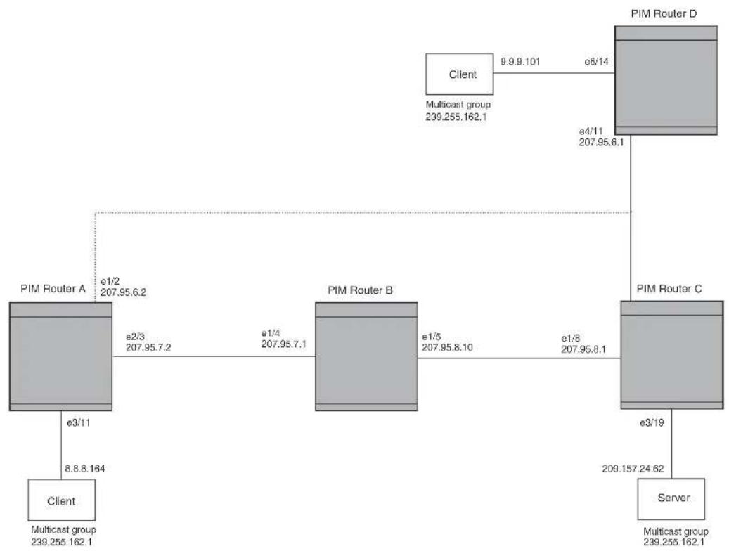
flowchart
graph TD
Client["Client\nMulticast group 239.255.162.1"] -->|e3/11\n8.8.8.164| PIMRouterA["PIM Router A\ne1/2\n207.95.6.2"]
Client -->|e3/11| PIMRouterB["PIM Router B\ne1/4\n207.95.7.1"]
PIMRouterA -->|e2/3\n207.95.7.2| PIMRouterB
PIMRouterB -->|e1/5\n207.95.8.10| PIMRouterC["PIM Router C\ne1/8\n207.95.8.1"]
PIMRouterC -->|e3/19\n209.157.24.62| Server["Server"]
Client -->|9.9.9.101 e6/14| PIMRouterD["PIM Router D\nClient Multicast group 239.255.162.1"]
PIMRouterD -->|e4/11\n207.95.6.1| PIMRouterD
To add a static route to a virtual interface, enter commands such as the following.
BigIron RX(config)# ip mroute 3 0.0.0.0 0.0.0.0 ve 1 distance 1 BigIron RX(config)# write memory
Configuring IP multicast traffic reduction
In Layer 2 mode, BigIron RX forwards all IP multicast traffic by default based on the Layer 2 information in the packets. Optionally, you can enable the BigIron RX to make forwarding decisions in hardware, based on multicast group by enabling the IP Multicast Traffic Reduction feature.
NOTE
The IP Multicast Traffic Reduction feature is applicable for Layer 2 mode only.
When this feature is enabled, the BigIron RX examines the MAC address in an IP multicast packet and forward the packet only on the ports from which the device has received Group Membership reports for that group, instead of forwarding all multicast traffic to all ports. The device sends traffic for other groups out all ports.
When you enable IP Multicast Traffic Reduction, you also can configure the following features:
- IGMP mode – When you enable IP Multicast Traffic Reduction, the device passively listens for IGMP Group Membership reports by default. If the multicast domain does not have a to send IGMP queries to elicit these Group Membership reports, you can enable the device to actively send the IGMP queries. The IGMP passive mode is also known as IGMP snooping and facilitates IP Multicast Traffic Reduction.
NOTE
A router-id is required if a virtual interface (ve) or IP is not configured for IGMP snooping to work.
- Query interval – The query interval specifies how often the device sends Group Membership queries. This query interval applies only to the active IGMP mode. The default is 60 seconds. You can change the interval to a value from 10 - 600 seconds.
- Age interval – The age interval specifies how long an IGMP group can remain in the IGMP group table without the device receiving a Group Membership report for the group. If the age interval expires before the device receives another Group Membership report for the group, the device removes the entry from the table. The default is 140 seconds. You can change the interval to a value from 10 – 1220 seconds.
Furthermore, when you enable IP Multicast Traffic Reduction, the device forwards all IP multicast traffic by default but you can enable the device to do the following:
- Forward IP multicast traffic only for groups for which the device has received a Group Membership report.
- Drop traffic for all other groups.
The following sections describe how to configure IP multicast traffic reduction and PIM SM Traffic Snooping parameters on a BigIron RX.
Enabling IP multicast traffic reduction
By default, the BigIron RX forwards all IP multicast traffic out all ports except the port on which the traffic was received. To reduce multicast traffic through the device, you can enable IP Multicast Traffic Reduction. This feature configures the device to forward multicast traffic only on the ports attached to multicast group members, instead of forwarding all multicast traffic to all ports. The device determines the ports that are attached to multicast group members based on entries in the IGMP table. Each entry in the table consists of MAC addresses and the ports from which the device has received Group Membership reports for that group.
By default, the device broadcasts traffic addressed to an IP multicast group that does not have any entries in the IGMP table. When you enable IP Multicast Traffic Reduction, the device determines the ports that are attached to multicast group members based on entries in the IGMP table. The IGMP table entries are created when the VLAN receives a group membership report for a group. Each entry in the table consists of an IP multicast group address and the ports from which the device has received Group Membership reports.
When the device receives traffic for an IP multicast group, the device looks in the IGMP table for an entry corresponding to that group. If the device finds an entry, the device forwards the group traffic out the ports listed in the corresponding entries, as long as the ports are members of the same VLAN. If the table does not contain an entry corresponding to the group or if the port is a member of the default VLAN, the device broadcasts the traffic.
NOTE
When one or more BigIron RX devices are running Layer 2 IP Multicast Traffic reduction, configure one of the devices for active IGMP and leave the other devices configured for passive IGMP. However, if the IP multicast domain contains a multicast-capable, configure all the BigIron RX devices for passive IGMP and allow the to actively send the IGMP queries.
NOTE
A router-id is required if a virtual interface (ve) or IP is not configured for IGMP snooping to work.
To enable IP Multicast Traffic Reduction, enter the following command.
BigIron RX(config)# ip multicast active
Syntax: [no] ip multicast active | passive
When you enable IP multicast on a BigIron RX, all ports on the device are configured for IGMP.
If you are using active IGMP, all ports can send IGMP queries and receive IGMP reports. If you are using passive IGMP, all ports can receive IGMP queries.
IP Multicast Traffic Reduction cannot be disabled on individual ports of a BigIron RX. IP Multicast Traffic Reduction must can be disabled globally by entering the no ip multicast command.
NOTE
If the "route-only" feature is enabled on the BigIron RX, then IP Multicast Traffic Reduction will not be supported.
To verify that IP Multicast Traffic Reduction is enabled, enter the following command at any level of the CLI.
BigIron RX(config)# show ip multicast IP multicast is enabled - Active
Syntax: show ip multicast
Configuring the IGMP mode per VLAN
NOTE
A router-id is required if a virtual interface (ve) or IP is not configured for IGMP snooping to work.
If the IP Multicast command is not applied globally as described in “Enabling IP multicast traffic reduction” on page 657, you can apply it to individual VLANs instances within their configurations. In the following example, multicast traffic reduction is applied using IGMP snooping to VLAN 2.
(config)# vlan 2 (config-vlan-2)# multicast passive
Syntax: [no] multicast active | passive
When you enable IP multicast for a specific VLAN instance, IGMP snooping is enabled. The device uses IGMP to maintain a table of the Group Membership reports received by the device for the specified VLAN instance. You can use active or passive IGMP mode. There is no default mode.
- Active – When active IGMP mode is enabled, the switch actively sends out IGMP queries to identify IP multicast groups within the VLAN instance and makes entries in the IGMP table based on the Group Membership reports received from the network.
Syntax: Passive – When passive IGMP mode is enabled, the switch listens for IGMP Group Membership reports on the VLAN instance specified but does not send IGMP queries. The passive mode is called “IGMP snooping”. Use this mode when another device in the VLAN instance is actively sending queries.
Configuring IGMP snooping tracking per VLAN instance
When IGMP Snooping Tracking is enabled, the BigIron RX immediately removes any GMP host port from the IP multicast group entry when it detects an IGMP-leave message on the specified host port without first sending out group-specific queries to the interface. By default, IGMP Snooping Tracking is disabled.
The ip multicast tracking command may be enabled globally as well as per VLAN basis. To enable IGMP Snooping Tracking globally, enter a command such as the following.
BigIron RX(config)# ip multicast tracking
Syntax: [no] ip multicast tracking
The no form of this command disables the tracking process globally.
To enable IGMP Snooping Tracking per VLAN, enter commands such as the following.
BigIron RX(config)# vlan 100 BigIron RX(config-vlan-100)# ip multicast tracking
Syntax: [no] ip multicast tracking
The no form of this command disables the tracking process per VLAN.
For IGMPv3, the above command also internally tracks all the IGMPv3 hosts behind a given port. The port is not removed from the IP multicast group entry in the forwarding table until all the hosts behind that port have left that multicast group. When the last IGMPv3 host sends a IGMPv3 leave message, the port is removed from the IP multicast group entry in the forwarding table immediately without first sending out group_source_specific query to the interface.
Syntax: [no] ip multicast tracking
The no form of this command disables the tracking process per VLAN instance.
Changing the IGMP mode
When you enable IP Multicast Traffic Reduction on the device, IGMP also is enabled. The device uses IGMP to maintain a table of the Group Membership reports received by the device. You can use active or passive IGMP mode. There is no default mode.
- Active – When active IGMP mode is enabled, a Brocade device actively sends out IGMP queries to identify IP multicast groups on the network and makes entries in the IGMP table based on the Group Membership reports received from the network.
NOTE
Routers in the network generally handle this operation. Use the active IGMP mode only when the device is in a stand-alone network with no external IP multicast attachments. In this case, enable the active IGMP mode on only one of the devices and leave the other devices configured for passive IGMP mode.
- Passive – When passive IGMP mode is enabled, the device listens for IGMP Group Membership reports but does not send IGMP queries. The passive mode is sometimes called "IGMP snooping". Use this mode when another device in the network is actively sending queries.
To enable active IGMP, enter the following command.
BigIron RX(config)# ip multicast active
BigIron RX(config)# write memory
BigIron RX(config)# end
BigIron RX# reload
Syntax: [no] ip multicast active | passive
To enable passive IGMP, enter the following command.
BigIron RX(config)# ip multicast passive
BigIron RX(config)# write memory
BigIron RX(config)# end
BigIron RX# reload
Modifying the query interval
If IP Multicast Traffic Reduction is set to active mode, you can modify the query interval, which specifies how often a BigIron RX enabled for active IP Multicast Traffic Reduction sends Group Membership queries.
NOTE
The query interval applies only to the active mode of IP Multicast Traffic reduction.
To modify the query interval, enter a command such as the following.
BigIron RX(config)# ip multicast query-interval 120
Syntax: [no] ip multicast query-interval
The
Modifying the age interval
When the device receives a Group Membership report, the device makes an entry in the IGMP group table for the group in the report. The age interval specifies how long the entry can remain in the table without the device receiving another Group Membership report.
To modify the age interval, enter a command such as the following.
BigIron RX(config)# ip multicast age-interval 280
Syntax: [no] ip multicast age-interval
The
Filtering multicast groups
By default, the BigIron RX forwards multicast traffic for all valid multicast groups. You can configure a BigIron RX to filter out all multicast traffic for groups other than the ones for which the device has received Group Membership reports.
When the device starts up, it forwards all multicast groups even though multicast traffic filters are configured. This process continues until the device receives a group membership report. Once the group membership report is received, the device drops all multicast packets for groups other than the ones for which the device has received the group membership report.
To enable IP multicast filtering, enter the following command.
BigIron RX(config)# ip multicast filter
Syntax: [no] ip multicast filter
NOTE
If the “route-only” feature is enabled on a BigIron RX, PIM SM traffic snooping will not be supported.
Layer 2 multicast filters
You can define multicast boundaries on a per VLAN basis. The multicast-boundary command allows you to configure a boundary on IGMP snooping enabled interface by defining which multicast groups may not forward packets over a specified interface.
Configuration considerations
- Only one ACL can be bound to any interface or VLAN.
- If a new multicast boundary has to be applied, you must delete the old bounder first, then apply the new ACL.
- To avoid temporary loss in multicast traffic, ACLs should be configured before applying them to multicast boundaries.
- Modifying an already applied ACL will take effect immediately.
- Configurations shoube be generated at the VLAN level if user has explicitly configured it, regardless of whether it matches the global snooping configuration.
- You can issue the "no multicast" command to erase all VLAN-level configuration and force the VLAN to inherit the global configuration.
- You can issue the [no] multicast active|passive command to explicitly set the VLAN-level configuration.
NOTE
Issuing the [no] multicast active | passive command causes this configuration to always be generated for this VLAN.
- Global configurations will not affect any explicit VLAN-level configurations.
Configuring Layer 2 multicast boundaries
You can define multicast boundaries on a per VLAN basis by entering commands such as the following.
BigIron RX(config)#vlan 100
BigIron RX(config-vlan-100)#multicast-boundary MyBrocadeAccessList ethernet 3/22
Syntax: [no] multicast-boundary
Use the acl-spec parameter to define the number or name identifying an access list that controls the range of group addresses affected by the boundary.
Use the port-list parameter to define the member ports on which the ACL is applied. The ACL will be applied to the multicast traffic arriving in both directions.
Use the no multicast boundary command to remove the boundary on an IGMP enabled interface.
NOTE
The ACL, MyBrocadeAccessList can be configured using standard ACL syntax which can be found in the ACL section.
PIM SM traffic snooping
By default, when a BigIron RX receives an IP multicast packet, the device does not examine the multicast information in the packet. Instead, the device simply forwards the packet out all ports except the port that received the packet. In some networks, this method can cause unnecessary traffic overhead in the network. For example, if the BigIron RX is attached to only one group source and two group receivers, but has devices attached to every port, the device forwards group traffic out all ports in the same broadcast domain except the port attached to the source, even though there are only two receivers for the group.
PIM SM traffic snooping eliminates the superfluous traffic by configuring the device to forward IP multicast group traffic only on the ports that are attached to receivers for the group.
PIM SM traffic snooping requires IP multicast traffic reduction to be enabled on the device. IP multicast traffic reduction configures the device to listen for IGMP messages. PIM SM traffic snooping provides a finer level of multicast traffic control by configuring the device to listen specifically for PIM SM join and prune messages sent from one PIM SM router to another through the device.
NOTE
This feature applies only to PIM SM version 2 (PIM V2).
Application examples
Figure 99 shows an example application of the PIM SM traffic snooping feature. In this example, a device is connected through an IP router to a PIM SM group source that is sending traffic for two PIM SM groups. The device also is connected to a receiver for each of the groups.
FIGURE 99 PIM SM traffic reduction in enterprise network
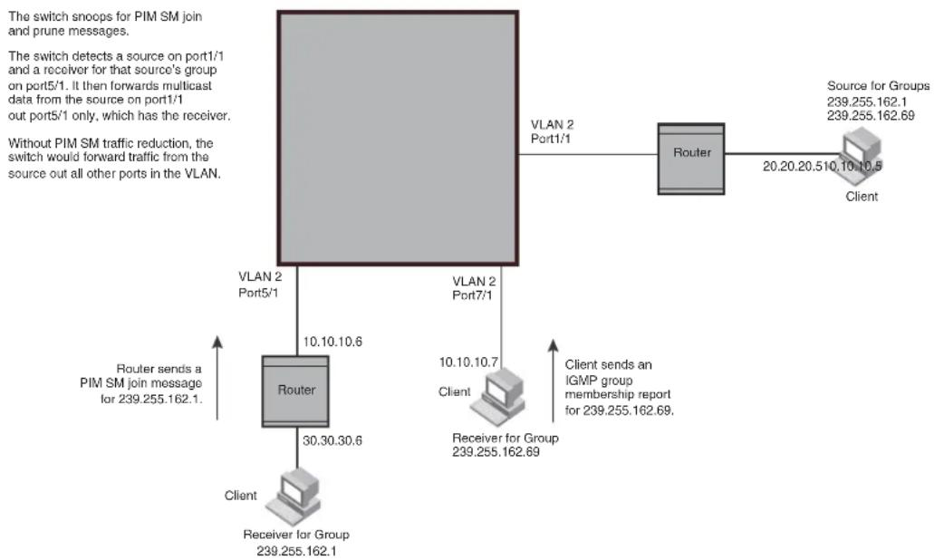
flowchart
graph TD
A["The switch snoops for PIM SM join and prune messages."] --> B["VLAN 2 Port1/1"]
B --> C["Router"]
C --> D["Client"]
D --> E["Receiver for Group 239.255.162.1"]
C --> F["Client sends an IGMP group membership report 239.255.162.69"]
C --> G["Client sends a PIM SM join message for 239.255.162.1"]
H["Without PIM SM traffic reduction"] --> I["VLAN 2 Port7/1"]
I --> J["Client"]
J --> K["Receiver for Group 239.255.162.69"]
I --> L["Client sends an IGMP group membership report 239.255.162.69"]
M["VLAN 2 Port5/1"] --> N["Router"]
N --> O["Client"]
O --> P["Receiver for Group 239.255.162.1"]
N --> Q["Client sends an IGMP group membership report 239.255.162.69"]
R["Source for Groups 239.255.162.1 239.255.162.69"] --> S["Router"]
S --> T["Client"]
When PIM SM traffic snooping is enabled, the device starts listening for PIM SM join and prune messages and IGMP group membership reports. Until the device receives a PIM SM join message or an IGMP group membership report, the device forwards IP multicast traffic out all ports. Once the device receives a join message or group membership report for a group, the device forwards subsequent traffic for that group only on the ports from which the join messages or IGMP reports were received.
In this example, the router connected to the receiver for group 239.255.162.1 sends a join message toward the group's source. Since PIM SM traffic snooping is enabled on the device, the device examines the join message to learn the group ID, then makes a forwarding entry for the group ID and the port connected to the receiver's router. The next time the device receives traffic for 239.255.162.1 from the group's source, the device forwards the traffic only on port 5/1, since that is the only port connected to a receiver for the group.
Notice that the receiver for group 239.255.162.69 is directly connected to the device. As a result, the device does not see a join message on behalf of the client. However, since IP multicast traffic reduction also is enabled, the device uses the IGMP group membership report from the client to select the port for forwarding traffic to group 239.255.162.69 receivers.
The IP multicast traffic reduction feature and the PIM SM traffic snooping feature together build a list of groups and forwarding ports for the VLAN. The list includes PIM SM groups learned through join messages as well as MAC addresses learned through IGMP group membership reports. In this case, even though the device never sees a join message for the receiver for group 239.255.162.69, the device nonetheless learns about the receiver and forwards group traffic to the receiver.
The device stops forwarding IP multicast traffic on a port for a group if the port receives a prune message for the group.
Notice that the ports connected to the source and the receivers are all in the same port-based VLAN on the device. This is required for the PIM SM snooping feature. The feature also requires the source and the downstream router to be on different IP subnets, as shown in Figure 99.
Figure 100 shows another example application for PIM SM traffic snooping. This example shows devices on the edge of a Global Ethernet cloud (a Layer 2 Packet over SONET cloud). Assume that each device is attached to numerous other devices such as other BigIron RXs.
FIGURE 100 PIM SM traffic reduction in global Ethernet environment

flowchart
graph TD
SwitchA["Switch A"] -->|VLAN 2 Port1/1| SwitchB["Switch B"]
SwitchA -->|VLAN 2 Port5/1| SwitchC["Switch C"]
SwitchA -->|VLAN 2 Port7/1| SwitchA
SwitchA -->|VLAN 2 Port1/1| SwitchB
SwitchA -->|VLAN 2 Port1/1| SwitchC
SwitchA -->|VLAN 2 Port1/1| Router
SwitchB -->|VLAN 2 Port5/1| Router
SwitchB -->|VLAN 2 Port5/1| Router
SwitchB -->|VLAN 2 Port5/1| Router
SwitchB -->|VLAN 2 Port5/1| Router
SwitchB -->|VLAN 2 Port5/1| Router
SwitchB -->|VLAN 2 Port5/1| Router
SwitchB -->|VLAN 2 Port5/1| Client
SwitchB -->|VLAN 2 Port5/1| Client
SwitchB -->|VLAN 2 Port5/1| Client
SwitchB -->|VLAN 2 Port5/1| Client
SwitchB -->|VLAN 2 Port5/1| Client
SwitchB -->|VLAN 2 Port5/1| Client
SwitchB -->|VLAN 2 Port5/1| Client
SwitchC["Switch C"] -->|VLAN 2 Port5/1| Router
SwitchC -->|VLAN 2 Port5/1| Router
SwitchC -->|VLAN 2 Port5/1| Router
SwitchC -->|VLAN 2 Port5/1| Router
SwitchC -->|VLAN 2 Port5/1| Router
SwitchC -->|VLAN 2 Port5/1| Router
SwitchC -->|VLAN 2 Port5/1| Router
SwitchC -->|VAN 2 Port5/1| Router
SwitchC -->|VAN 2 Port5/1| Router
SwitchC -->|VAN 2 Port5/1| Router
SwitchC -->|VAN 2 Port5/1| Router
SwitchC -->|VAN 2 Port5/1| Router
SwitchC -->|VAN 2 Port5/1| Router
SwitchC -->|VAN 2 Port1/1| Router
SwitchC -->|VAN 2 Port1/1| Router
SwitchC -->|VAN 2 Port1/1| Router
SwitchC -->|VAN 2 Port1/1| Router
SwitchC -->|VAN 2 Port1/1| Router
SwitchC -->|VAN 2 Port1/1| Router
SwitchC -->|VAN 2 Port1/1|Router
SwitchC -->|VAN 2 Port1/1|Router
SwitchC -->|VAN 2 Port1/1|Router
SwitchC -->|VAN 2 Port1/1|Router
SwitchC -->|VAN 2 Port1/1|Router
SwitchC -->|VAN 2 Port1/1|Router
SwitchC -->|VAN 2 Port1/1|Router
SwitchA -->|VLAN 2 Port1/1| Router
SwitchA -->|VLAN 2 Port5/1| Router
SwitchA -->|VLAN 2 Port7/1| Router
SwitchA -->|VLAN 2 Port1/1| Router
SwitchA -->|VLAN 2 Port1/1| Router
SwitchA -->|VAN 2 Port5/1| Router
SwitchA -->|VAN 2 Port5/1| Router
SwitchA -->|VAN 2 Port5/1| Router
SwitchA -->|VAN 2 Port5/1| Router
SwitchA -->|VAN 2 Port5/1| Router
SwitchA -->|VAN 2 Port5/1| Router
SwitchA -->|VAN 2 Port5/1|Router
SwitchA -->|VAN 2 Port5/1|Router
SwitchA -->|VAN 2 Port5/1|Router
SwitchA -->|VAN 2 Port5/1|Router
SwitchA -->|VAN 2 Port5/1|Router
SwitchA -->|VAN 2 Port5/1|Router
SwitchA -->|VAN 2 Port5/1|Router
SwitchB["Switch B"] --> VLAN_2["Router"]
SwitchB --> VLAN_2["Router"]
SwitchB --> VLAN_2["Router"]
SwitchB --> VLAN_2["Router"]
SwitchB --> VLAN_2["Router"]
SwitchB --> VLAN_2["Router"]
SwitchB --> VLAN_2["Router"]
SwitchB --> VLAN_2["Router"]
SwitchB --> VLAN_2["Router"]
SwitchB --> VLAN_2["Router"]
SwitchB <--> VLAN_2["Router"]
The devices on the edge of the Global Ethernet cloud are configured for IP multicast traffic reduction and PIM SM traffic snooping. Although this application uses multiple devices, the feature has the same requirements and works the same way as it does on a single device.
Configuration requirements
- IP multicast traffic reduction must be enabled on the device that will be running PIM SM snooping. The PIM SM traffic snooping feature requires IP multicast traffic reduction.
NOTE
Use the passive mode of IP multicast traffic reduction instead of the active mode. The passive mode assumes that a router is sending group membership queries as well as join and prune messages on behalf of receivers. The active mode configures the device to send group membership queries.
- All the device ports connected to the source and receivers or routers must be in the same port-based VLAN.
- The PIM SM snooping feature assumes that the group source and the device are in different subnets and communicate through a router. The source must be in a different IP subnet than the receivers. A PIM SM router sends PIM join and prune messages on behalf of a multicast group receiver only when the router and the source are in different subnets. When the receiver and source are in the same subnet, they do not need the router in order to find one another. They find one another directly within the subnet.
The device forwards all IP multicast traffic by default. Once you enable IP multicast traffic reduction and PIM SM traffic snooping, the device initially blocks all PIM SM traffic instead of forwarding it. The device forwards PIM SM traffic to a receiver only when the device receives a join message from the receiver. Consequently, if the source and the downstream router are in the same subnet, and PIM SM traffic snooping is enabled, the device blocks the PIM SM traffic and never starts forwarding the traffic. This is because the device never receives a join message from the downstream router for the group. The downstream router and group find each other without a join message because they are in the same subnet.
NOTE
If the "route-only" feature is enabled on a BigIron RX, PIM SM traffic snooping will not be supported.
Enabling PIM SM traffic snooping
To enable PIM SM traffic snooping, enter the following commands at the global CONFIG level of the CLI.
BigIron RX(config)# ip multicast BigIron RX(config)# ip pimsm-snooping
The first command enables IP multicast traffic reduction. This feature is similar to PIM SM traffic snooping but listens only for IGMP information, not PIM SM information. You must enable both IP multicast traffic reduction and PIM SM traffic snooping to enable the device to listen for PIM SM join and prune messages.
Syntax: [no] ip multicast [active | passive]
This command enables IP multicast traffic reduction. The active | passive parameter specifies the mode. The PIM SM traffic snooping feature assumes that the network has routers that are running PIM SM.
Syntax: [no] ip pimsm-snooping
This command enables PIM SM traffic snooping.
To disable the feature, enter the following command.
BigIron RX(config)# no ip pimsm-snooping
If you also want to disable IP multicast traffic reduction, enter the following command.
BigIron RX(config)# no ip multicast
Configuring the PIM SM traffic snooping per VLAN instance
If PIM SM Traffic snooping is not applied globally, you can apply it to individual VLANs instances within their configurations. In the following example, multicast traffic reduction is applied using PIM SM Traffic snooping to VLAN 2.
(config)# vlan 2 (config-vlan-2)# multicast pimsm-snooping
Syntax: [no] multicast pimsm-snooping
Configuring PIM proxy per VLAN instance
Using the PIM proxy function, multicast traffic can be reduced by configuring an BigIron RX switch to issue PIM join and prune messages on behalf of hosts that the configured switch discovers through standard PIM interfaces. The switch is then able to act as a proxy for the discovered hosts and perform PIM tasks upstream of the discovered hosts. Where there are multiple PIM downstream switches, this removes the need to send multiple messages.
To configure a BigIron RX switch to function as a PIM proxy on VLAN 2, use the following commands.
(config)# vlan 2
(config-vlan-2)# multicast pim-proxy-enable
Syntax: [no] multicast pim-proxy-enable
Static IGMP membership
When configuring a static IGMP membership, you have two options.
The multicast static-group uplink command which sends the traffic to the switch, and saves a port.
The multicast static-group
Configuring a multicast static group uplink per VLAN
When the multicast static-group uplink command is enabled on a snooping VLAN, the snooping device behaves like an IGMP host on ports connected to the multicast switch. The snooping device will respond to IGMP queries from the uplink multicast PIM switch for the groups and sources configured. Upon the multicast switch receiving the IGMP join message, it will initiate the PIM join on its upstream path towards the source to pull the source traffic down. The source traffic will stop at the IGMP snooping device. The traffic will then be forwarded to the multicast receiver and switch ports or dropped in hardware if no other multicast receiver and switches are present in the VLAN.
The multicast static-group uplink command can be configured under the VLAN configuration only.
When using IGMP v3, you can use the multicast static-group include or multicast static-group exclude command to statically include or exclude multicast traffic, respectively for hosts that cannot signal group membership dynamically.
To configure the snooping device to statically join a multicast group on the uplink interface, enter commands such as the following.
BigIron RX(config)# vlan 100
BigIron RX(config-vlan-100)# multicast static-group 224.10.1.1 uplink
To configure the physical interface 10.43.3.12 to statically join a multicast group on port 2/4, enter commands such as the following.
BigIron RX(config)# vlan 100
BigIron RX((config-vlan-100)# multicast static-group 224.10.1.1 2/4
To configure the snooping device to statically join a multicast stream with the source address of 10.43.1.12 in the include mode, enter commands such as the following.
BigIron RX(config)# vlan 100
BigIron RX(config-vlan-100)# multicast static-group 224.10.1.1 include 10.43.1.12 uplink
To configure the snooping device to statically join all multicast streams on the uplink interface excluding the stream with source address 10.43.1.12, enter commands such as the following.
BigIron RX(config)# vlan 100
BigIron RX(config-vlan-100)# multicast static-group 224.10.1.1 exclude 10.43.1.12 uplink
Configuring multicast static group per VLAN
When the multicast static-group
The multicast static-group
To configure the physical interface ethernet 2/4 to statically join a multicast group, enter commands such as the following.
BigIron RX(config)# vlan 100
BigIron RX(config-vlan-100)# multicast static-group 224.10.1.1 ethernet 2/4
To configure the physical interface ethernet 3/4 to statically join a multicast stream with source address of 10.43.1.12 in the include mode, enter commands such as the following.
BigIron RX(config)# vlan 100
BigIron RX(config-vlan-100)# multicast static-group 224.10.1.1 include 10.43.1.12 ethernet 3/4
To configure the physical interface ethernet 3/4 to statically join all multicast streams on the uplink interface excluding the stream with source address of 10.43.1.12, enter commands such as the following.
BigIron RX(config)# vlan 100
BigIron RX(config-vlan-100)# multicast static-group 224.10.1.1 exclude 10.43.1.12 ethernet 3/4
Syntax: [no] multicast static-group
Syntax: [no] multicast static-group
IGMP v3 commands
Syntax: [no] multicast static-group
Syntax: [no] multicast static-group
The group-address parameter specifies the group multicast address.
The include or exclude keyword indicates a filtering action. You can specify which source (for a group) to include or exclude. The include or exclude keyword is only supported on IGMPv3.
The source-address parameter specifies the IP address of the multicast source. Each address must be added or deleted one line per source.
The uplink parameter specifies the port as an uplink port that can receive multicast data for the configured multicast groups. Upstream traffic will be sent to the switch and will not use a port.
The port-list parameter specifies the range of ports to include in the configuration.
The no form of this command removes the static multicast definition. Each configuration must be deleted separately.
Overview of Routing Information Protocol (RIP)
Routing Information Protocol (RIP) is an IP route exchange protocol that uses a distance vector (a number representing distance) to measure the cost of a given route. The cost is a distance vector because the cost often is equivalent to the number of router hops between the device and the destination network.
A device can receive multiple paths to a destination. The software evaluates the paths, selects the best path, and saves the path in the IP route table as the route to the destination. Typically, the best path is the path with the fewest hops. A hop is another router through which packets must travel to reach the destination. If the device receives a RIP update from another router that contains a path with fewer hops than the path stored in the device's route table, the device replaces the older route with the newer one. The device then includes the new path in the updates it sends to other RIP routers, including the device.
RIP routers, including the BigIron RX, also can modify a route's cost, generally by adding to it, to bias the selection of a route for a given destination. In this case, the actual number of router hops may be the same, but the route has an administratively higher cost and is thus less likely to be used than other, lower-cost routes.
A RIP route can have a maximum cost of 15. Any destination with a higher cost is considered unreachable. Although limiting to larger networks, the low maximum hop count prevents endless loops in the network.
Configuring RIP parameters
Use the following procedures to configure RIP parameters on a system-wide and individual interface basis.
Enabling RIP
RIP is disabled by default. To enable RIP, you must enable it globally and also on individual interfaces on which you want to advertise RIP. Globally enabling the protocol does not enable it on individual interfaces. You can enable the protocol on physical interfaces as well as virtual routing interfaces. When you enable RIP on a port, you also must specify the version (version 1 only, version 2 only, or version 1 compatible with version 2).
To enable RIP globally, enter the following command.
BigIron RX(config)# router rip
Syntax: [no] router rip
After globally enabling the protocol, you must enable it on individual interfaces. To enable RIP on an interface, enter commands such as the following.
BigIron RX(config)# interface ethernet 1/1 BigIron RX(config-if-e1000-1/1)# ip rip v1-only
Syntax: [no] ip rip v1-only | v1-compatible-v2 | v2-only
Configuring metric parameters
By default, a device port increases the cost of a RIP route that is learned or advertised on the port by one. You can configure individual ports to add more than one to a learned or advertised route's cost.
Changing the cost of routes learned or advertised on a port
By default, a device port increases the cost of a RIP route that is learned on the port. The device increases the cost by adding one to the route's metric before storing the route.
You can change the amount that an individual port adds to the metric of RIP routes learned on the port.
To increase the metric for learned routes, enter commands such as the following.
BigIron RX(config-if-e1000-1/1)# ip rip metric-offset 5 in
The command configures port 1/1 to add 5 to the cost of each route it learns.
Syntax: [no] ip rip metric-offset
The number is 1-16. A route with a metric of 16 is unreachable. Use 16 only if you do not want the route to be used. In fact, you can prevent the device from using a specific port for routes learned though that port by setting its metric to 16.
In applies to routes the port learns from RIP neighbors.
Out applies to routes the port advertises to its RIP neighbors.
Changing the administrative distance
By default, the device assigns the default RIP administrative distance (120) to RIP routes. When comparing routes based on administrative distance, the device selects the route with the lower distance. You can change the administrative distance for RIP routes.
NOTE
Refer to “Changing administrative distances” on page 767 for a list of the default distances for all route sources.
To change the administrative distance for RIP routes, enter a command such as the following.
BigIron RX(config-rip-router)# distance 140
The command changes the administrative distance to 140 for all RIP routes.
Syntax: [no] distance
The number is 1 - 255.
Configuring redistribution
You can configure the device to redistribute routes learned through OSPF or BGP4, connected into RIP, or static routes. When you redistribute a route from one of these other protocols into RIP, the device can use RIP to advertise the route to its RIP neighbors.
To configure redistribution, perform the following tasks:
- Configure redistribution filters. You can configure filters to permit or deny redistribution for a route based on its origin (OSPF, BGP4, and so on), the destination network address, and the route's metric. You also can configure a filter to set the metric based on these criteria.
- Change the default redistribution metric (optional). The device assigns a RIP metric of one to each redistributed route by default. You can change the default metric to a value up to 16.
Configuring redistribution filters
RIP redistribution filters apply to all interfaces. You use route maps to define how you want to deny or permit redistribution.
NOTE
The default redistribution action is permit, even after you configure and apply redistribution filters to the virtual routing interface. If you want to tightly control redistribution, apply a filter to deny all routes as the last filter (the filter with the highest ID), then apply filters to allow specific routes.
A route map is a named set of match conditions and parameter settings that the router can use to modify route attributes and to control redistribution of the routes into other protocols. A route map consists of a sequence of up to 50 instances. If you think of a route map as a table, an instance is a row in that table. The router evaluates a route according to a route map's instances in ascending numerical order. The route is first compared against instance 1, then against instance 2, and so on. As soon as a match is found, the router stops evaluating the route against the route map instances.
Route maps can contain match statements and set statements. Each route map contains a "permit" or "deny" action for routes that match the match statements.
- If the route map contains a permit action, a route that matches a match statement is permitted; otherwise, the route is denied.
- If the route map contains a deny action, a route that matches a match statement is denied.
- If a route does not match any match statements in the route map, the route is denied. This is the default action. To change the default action, configure the last match statement in the last instance of the route map to "permit any any".
- If there is no match statement, the software considers the route to be a match.
- For route maps that contain address filters, AS-path filters, or community filters, if the action specified by a filter conflicts with the action specified by the route map, the route map's action takes precedence over the individual filter's action.
If the route map contains set statements, routes that are permitted by the route map's match statements are modified according to the set statements.
In RIP, the match statements are based on prefix lists and access control lists. Set statements are based on tag values and metric values.
To configure redistribution filters, enter a command such as the following.
BigIron RX(config-rip-router)#redistribute bgp route-map longroute
Syntax: redistribute connected | bgp | ospf | static [metric
The connected parameter applies redistribution to connected types.
The bgp parameter applies redistribution to BGP4 routes.
The ospf parameter applies redistribution to OSPF routes.
The static parameter applies redistribution to IP static routes.
The metric
The route-map
Changing the default redistribution metric
When the device redistributes a route into RIP, the software assigns a RIP metric (cost) to the route. By default, the software assigns a metric of one to each route that is redistributed into RIP. You can increase the metric that the device assigns, up to 15.
To change the RIP metric the device assigns to redistributed routes, enter a command such as the following.
BigIron RX(config-rip-router)# default-metric 10
This command assigns a RIP metric of 10 to each route that is redistributed into RIP.
Syntax: [no] default-metric <1-15>
Configuring route learning and advertising parameters
By default, a device learns routes from all its RIP neighbors and advertises RIP routes to those neighbors.
You can configure the following learning and advertising parameters:
- Learning and advertising of RIP default routes – The device learns and advertises RIP default routes by default. You can disable learning and advertising of default routes on a global or individual interface basis.
- Learning of standard RIP routes – By default, the device can learn RIP routes from all its RIP neighbors. You can configure RIP neighbor filters to explicitly permit or deny learning from specific neighbors.
Enabling learning of RIP default routes
By default, the device does not learn default RIP routes. You can enable learning of RIP default routes on a global or interface basis.
To enable learning of default RIP routes on a global basis, enter the following command.
BigIron RX(config-rip-router)# learn-default
Syntax: [no] learn-default
To enable learning of default RIP routes on an interface, enter commands such as the following.
BigIron RX(config)# interface ethernet 1/1 BigIron RX(config-if-e10000-1/1)# ip rip learn-default
Syntax: [no] ip rip learn-default
Configuring a RIP neighbor filter
By default, a device learns RIP routes from all its RIP neighbors. Neighbor filters allow you to specify the neighbor routers from which the device can receive RIP routes. Neighbor filters apply globally to all ports.
To configure a RIP neighbor filters, enter a command such as the following.
BigIron RX(config-rip-router)# neighbor 1 deny any
Syntax: [no] neighbor
This command configures the device so that the device does not learn any RIP routes from any RIP neighbors.
The following commands configure the device to learn routes from all neighbors except 192.168.1.170. Once you define a RIP neighbor filter, the default action changes from learning all routes from all neighbors to denying all routes from all neighbors except the ones you explicitly permit. Thus, to deny learning from a specific neighbor but allow all other neighbors, you must add a filter that allows learning from all neighbors. Make sure you add the filter to permit all neighbors as the last filter (the one with the highest filter number). Otherwise, the software can match on the permit all filter before a filter that denies a specific neighbor, and learn routes from that neighbor.
BigIron RX(config-rip-router)# neighbor 2 deny 192.16.1.170
BigIron RX(config-rip-router)# neighbor 1024 permit any
Changing the route loop prevention method
RIP uses the following methods to prevent routing loops:
- Split horizon – The device does not advertise a route on the same interface as the one on which the router learned the route.
- Poison reverse – The device assigns a cost of 16 (“infinite” or “unreachable”) to a route before advertising it on the same interface as the one on which the router learned the route. This is the default.
These loop prevention methods are configurable on a global basis as well as on an individual interface basis. One of the methods is always in effect on an interface enabled for RIP. Thus, if you disable one method, the other method is enabled.
NOTE
These methods are in addition to RIP's maximum valid route cost of 15.
To disable poison reverse and enable split horizon on a global basis, enter the following command.
BigIron RX(config-rip-router)# no poison-reverse
Syntax: [no] poison-reverse
To disable poison reverse and enable split horizon on an interface, enter commands such as the following.
BigIron RX(config-if-e10000-1/1)# no ip rip poison-reverse
Syntax: [no] ip rip poison-reverse
To disable split horizon and enable poison reverse on an interface, enter the command such as the following.
BigIron RX(config-if-e10000-1/1)# ip rip poison-reverse
You can configure the device to avoid routing loops by advertising local RIP routes with a cost of 16 ("infinite" or "unreachable") when these routes go down.
BigIron RX(config-rip-router)# poison-local-routes
Syntax: [no] poison-local-routes
Suppressing RIP route advertisement on a VRRP or VRRPE backup interface
NOTE
This section applies only if you configure the device for Virtual Router Redundancy Protocol (VRRP) or VRRP Extended (VRRPE). Refer to Chapter 17, "Configuring VRRP and VRRPE".
Normally, a VRRP or VRRPE Backup includes route information for the virtual IP address (the backed up interface) in RIP advertisements. As a result, other routers receive multiple paths for the backed up interface and might sometimes unsuccessfully use the path to the Backup rather than the path to the Master.
You can prevent the Backups from advertising route information for the backed up interface by enabling suppression of the advertisements.
To suppress RIP advertisements for the backed up interface in Router2, enter the following commands.
Router2(config)# router rip Router2(config-rip-router)# use-vrrp-path
Syntax: [no] use-vrrp-path
The syntax is the same for VRRP and VRRPE.
Using prefix lists and route maps as route filters
You can configure prefix lists to permit or deny specific routes, then apply them globally or to individual interfaces and specify whether the lists apply to learned routes (in) or advertised routes (out).
You can configure route maps to permit or deny specific routes, then apply a route map to an interface, and specify whether the map applies to learned routes (in) or advertised routes (out).
NOTE
A route is defined by the destination's IP address and network mask.
NOTE
By default, routes that do not match a prefix list are learned or advertised. To prevent a route from being learned or advertised, you must configure a prefix list to deny the route.
To configure a prefix list, enter commands such as the following.
BigIron RX(config)# ip prefix-list list1 permit 192.53.4.1 255.255.255.0
BigIron RX(config)# ip prefix-list list2 permit 192.53.5.1 255.255.255.0
BigIron RX(config)# ip prefix-list list3 permit 192.53.6.1 255.255.255.0
BigIron RX(config)# ip prefix-list list4 deny 192.53.7.1 255.255.255.0
The prefix lists permit routes to three networks, and deny the route to one network.
Since the default action is permit, all other routes (routes not explicitly permitted or denied by the filters) can be learned or advertised.
Syntax: ip prefix-list
To apply a prefix list at the global level of RIP, enter commands such as the following.
BigIron RX(config-rip-router)# prefix-list list1 in
Syntax: [no] prefix-list
To apply prefix lists to a RIP interface, enter commands such as the following.
BigIron RX(config-if-e1000-1/2)# ip rip prefix-list list2 in BigIron RX(config-if-e1000-1/2)# ip rip prefix-list list3 out
Syntax: [no] ip rip prefix-list
In applies the prefix list to routes the device learns from its neighbor on the interface.
Out applies the prefix list to routes the device advertises to its neighbor on the interface.
The commands apply RIP list2 route filters to all routes learned from the RIP neighbor on port 1/2 and applies the lists to all routes advertised on port 1/2.
To apply a route map to a RIP interface, enter commands such as the following.
BigIron RX(config-if-e1000-1/2)# ip rip route-map map1 in
Syntax: [no] ip rip route-map
The route-map
In applies the route map to routes the device learns from its neighbor on the interface.
Out applies the route map to routes the device advertises to its neighbor on the interface.
The commands apply route map map1 as route filters to routes learned from the RIP neighbor on port 1/2.
Setting RIP timers
You can set basic update timers for the RIP protocol. The protocol must be enabled in order to set the timers.
To set the timers.
BigIron RX(config) router rip
BigIron RX(config-rip-router)# timers 50
Syntax: [no] timers
Possible values: 3 - 21845 seconds
Default: 30 seconds
The command specifies how often RIP update messages are sent.
Displaying RIP filters
To display RIP filters, enter the following command at any CLI level.
BigIron RX> show ip rip
RIP Summary
Default port 520
Administrative distance is 120
updates every 30 seconds, expire after 180
Holddown lasts 180 seconds, garbage collect after 120
Last broadcast 30, Next Update 29
Need trigger update 0, next trigger broadcast 1
Minimum update interval 25, Max update offset 5
Split horizon is on; poison reverse is off
import metric 1
Default routes are accepted
Prefix List, Inbound, Not set
Prefix List, Outbound, Not set
Redistribute: CONNECTED Metric : 0 Routemap : Not Set
Static Metric : 1 Routemap : map1 .not defined.
OSPF Metric : 1 Routemap : Not Set
RIP Neighbor Filter Table
Index Action Neighbor IP Address
1 permit any
Syntax: show ip rip
This display shows the following information.
TABLE 108 CLI display of neighbor filter information
| This field... Displays... | |
| RIP Summary area | Shows the current configuration of RIP on the device. |
| Stat ic metric | Shows the static metric configuration. ".not defined" means the route map has not been distributed. |
| OSPF metric Shows what OSPF route map has been applied. | |
| Neighbor filter table area | |
| Index The filter number. You assign this number when you configure the filter. | |
| Action The action the router takes for RIP route packets to or from the specified neighbor:deny- If the filter is applied to an interface's outbound filter group, the filter prevents the router from advertising RIP routes to the specified neighbor on that interface. If the filter is applied to an interface's inbound filter group, the filter prevents the router from receiving RIP updates from the specified neighbor.permit- If the filter is applied to an interface's outbound filter group, the filter allows the router to advertise RIP routes to the specified neighbor on that interface. If the filter is applied to an interface's inbound filter group, the filter allows the router to receive RIP updates from the specified neighbor. | |
Neighbor IP Address The IP address of the RIP neighbor.
Clearing the RIP routes from the routing table
Clearing all the routes from the routing table
To clear RIP local routes, enter a command such as the following.
BigIron RX(config)#clear ip rip local routes
Syntax: clear ip rip local routes
To clear the RIP routes from the RIP database, enter a command such as the following.
BigIron RX(config)# clear ip rip routes
Syntax: clear ip rip routes
Use the ip address to specify which routes in the database you want to clear.
Use the subnet mask to specify which subnets you want to clear.
NOTE
Using the clear ip route command will not clear routes learned through RIP.
Overview of OSPF (Open Shortest Path First)
OSPF is a link-state routing protocol. The protocol uses link-state advertisements (LSA) to update neighboring routers regarding its interfaces and information on those interfaces. The router floods these LSAs to all neighboring routers to update them regarding the interfaces. Each router maintains an identical database that describes its area topology to help a router determine the shortest path between it and any neighboring router.
The device supports the following types of LSAs, which are described in RFC 2328 and 3101:
- Router link
- Network link
- Summary link
• Autonomous system (AS) summary link - AS external link
- Not-So-Stubby Area (NSSA) external link
OSPF is built upon a hierarchy of network components. The highest level of the hierarchy is the Autonomous System (AS). An autonomous system is defined as a number of networks, all of which share the same routing and administration characteristics.
An AS can be divided into multiple areas as shown in Figure 101 on page 680. Each area represents a collection of contiguous networks and hosts. Areas limit the area to which link-state advertisements are broadcast, thereby limiting the amount of flooding that occurs within the network. An area is represented in OSPF by either an IP address or a number.
You can further limit the broadcast area of flooding by defining an area range. The area range allows you to assign an aggregate value to a range of IP addresses. This aggregate value becomes the address that is advertised instead all of the individual addresses it represents being advertised. You can assign up to 32 ranges in an OSPF area.
An OSPF router can be a member of multiple areas. Routers with membership in multiple areas are known as Area Border Routers (ABRs). Each ABR maintains a separate topological database for each area the router is in. Each topological database contains all of the LSA databases for each router within a given area. The routers within the same area have identical topological databases. The ABR is responsible for forwarding routing information or changes between its border areas.
An Autonomous System Boundary Router (ASBR) is a router that is running multiple protocols and serves as a gateway to routers outside an area and those operating with different protocols. The ASBR is able to import and translate different protocol routes into OSPF through a process known as redistribution. For more details on redistribution and configuration examples, refer to “Enable route redistribution” on page 705.
FIGURE 101 OSPF operating in a network

flowchart
graph TD
A["Area 0.0.0 Backbone"] --> B["Router D"]
B --> C["Area Border Router (ABR)"]
C --> D["Router E"]
D --> E["Virtual Link"]
E --> F["Router F"]
F --> G[" Autonomous System Border Router (ASBR)"]
G --> H["Router G"]
H --> I["RIP Router"]
J["Router A"] --> K["Router C"]
L["Router B"] --> M["Router F"]
N["Router C"] --> O["Router A"]
P["Router D"] --> Q["Router B"]
R["Router E"] --> S["Router F"]
T["Router G"] --> U["RIP Router"]
Designated routers in multi-access networks
In a network that has multiple routers attached, OSPF elects one router to serve as the designated router (DR) and another router on the segment to act as the backup designated router (BDR). This arrangement minimizes the amount of repetitive information that is forwarded on the network by forwarding all messages to the designated router and backup designated routers responsible for forwarding the updates throughout the network.
Designated router election in multi-access networks
In a network with no designated router and no backup designated router, the neighboring router with the highest priority is elected as the DR, and the router with the next largest priority is elected as the BDR, as shown in Figure 102
FIGURE 102 Designated and backup router election
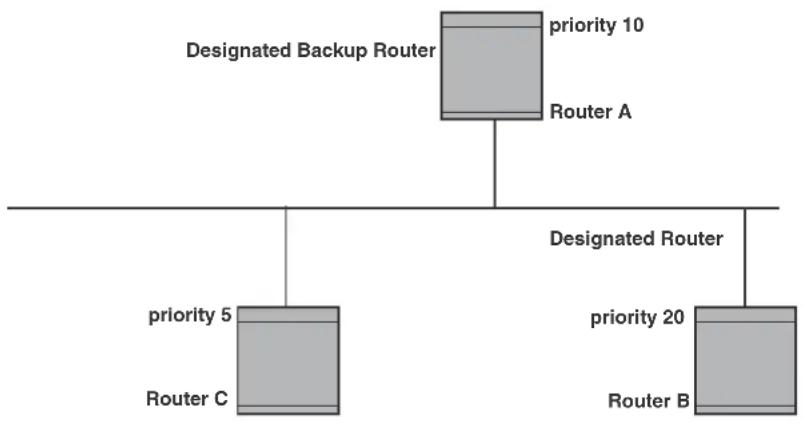
flowchart
graph TD
A["Designated Backup Router"] --> B["priority 10"]
A --> C["Router A"]
A --> D["priority 5"]
A --> E["Router C"]
F["Designated Router"] --> G["priority 20"]
F --> H["Router B"]
If the DR goes off-line, the BDR automatically becomes the DR. The router with the next highest priority becomes the new BDR. This process is shown in Figure 103.
NOTE
Priority is a configurable option at the interface level. You can use this parameter to help bias one router as the DR.
FIGURE 103 Backup designated router becomes designated router
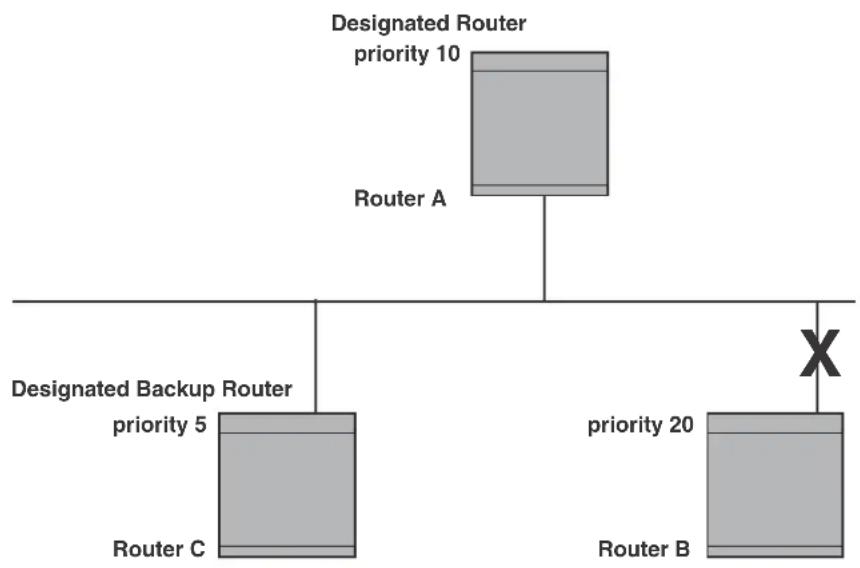
flowchart
graph TD
A["Router A\nDesignated Router\npriority 10"] --> B["Router B\npriority 20"]
B --> C["Router C\nPriority 5"]
B --> D["Designated Backup Router\npriority 5"]
B --> E["X"]
If two neighbors share the same priority, the router with the highest router ID is designated as the DR. The router with the next highest router ID is designated as the BDR.
NOTE
By default, the Brocade router ID is the IP address configured on the lowest numbered loopback interface. If the device does not have a loopback interface, the default router ID is the lowest numbered IP address configured on the device. For more information or to change the router ID, refer to "Changing the router ID" on page 182.
When multiple routers on the same network are declaring themselves as DRs, then both priority and router ID are used to select the designated router and backup designated routers.
When only one router on the network claims the DR role despite neighboring routers with higher priorities or router IDs, this router remains the DR. This is also true for BDRs.
The DR and BDR election process is performed when one of the following events occurs:
- an interface is in a waiting state and the wait time expires
- an interface is in a waiting state and a hello packet is received that addresses the BDR
- a change in the neighbor state occurs, such as:
- a neighbor state transitions from ATTEMPT state to a higher state
- communication to a neighbor is lost
- a neighbor declares itself to be the DR or BDR for the first time
OSPF RFC 1583 and 2328 compliance
Brocade routers are configured, by default, to be compliant with the RFC 1583 OSPF V2 specification. Brocade routers can also be configured to operate with the latest OSPF standard, RFC 2328.
NOTE
For details on how to configure the system to operate with the RFC 2328, refer to “Modify OSPF standard compliance setting” on page 718.
Reduction of equivalent AS external LSAs
An OSPF ASBR uses AS External link advertisements (AS External LSAs) to originate advertisements of a route learned from another routing domain, such as a BGP4 or RIP domain. The ASBR advertises the route to the external domain by flooding AS External LSAs to all the other OSPF routers (except those inside stub networks) within the local OSPF Autonomous System (AS).
In some cases, multiple ASBRs in an AS can originate equivalent LSAs. The LSAs are equivalent when they have the same cost, the same next hop, and the same destination. The device optimizes OSPF by eliminating duplicate AS External LSAs in this case. The device with the lower router ID flushes the duplicate External LSAs from its database and thus does not flood the duplicate External LSAs into the OSPF AS. AS External LSA reduction therefore reduces the size of the device's link state database. The AS External LSA reduction is described in RFC 2328
Figure 104 shows an example of the AS External LSA reduction feature. In this example, Routers D and E are OSPF ASBRs, and thus communicate route information between the OSPF AS, which contains Routers A, B, and C, and another routing domain, which contains Router F. The other routing domain is running another routing protocol, such as BGP4 or RIP. Routers D, E, and F, therefore, are each running both OSPF and either BGP4 or RIP.
FIGURE 104 AS external LSA reduction

flowchart
graph TD
subgraph "OSPF Autonomous System (AS)"
A["Router A"] --> D["Router D"]
B["Router B"] --> D
C["Router C"] --> E["Router E"]
end
subgraph "Another routing domain (such as BGP4 or RIP)"
F["Router F"] --> E
D --> E
E --> F
end
D -->|Routers D, E, and F are OSPF ASBRs and EBGP routers.| D
E -->|Router E, Router ID: 1.1.1.1| E
A --> D
B --> D
C --> D
D -->|Routers D, E, and F are OSPF ASBRs and EBGP routers.| D
E -->|Router E, Router ID: 2.2.2.2| E
Notice that both Router D and Router E have a route to the other routing domain through Router F.
OSPF eliminates the duplicate AS External LSAs. When two or more BigIron RX switches are configured as ASBRs have equal-cost routes to the same next-hop router in an external routing domain, the ASBR with the highest router ID floods the AS External LSAs for the external domain into the OSPF AS, while the other ASBRs flush the equivalent AS External LSAs from their databases. As a result, the overall volume of route advertisement traffic within the AS is reduced and the BigIron RX switches that flush the duplicate AS External LSAs have more memory for other OSPF data. In Figure 104, since Router D has a higher router ID than Router E, Router D floods the AS External LSAs for Router F to Routers A, B, and C. Router E flushes the equivalent AS External LSAs from its database.
Algorithm for AS external LSA reduction
Figure 104 shows an example in which the normal AS External LSA reduction feature is in effect. The behavior changes under the following conditions:
- There is one ASBR advertising (originating) a route to the external destination, but one of the following happens:
- A second ASBR comes on-line - A second ASBR that is already on-line begins advertising an equivalent route to the same destination.
In either case above, the router with the higher router ID floods the AS External LSAs and the other router flushes its equivalent AS External LSAs. For example, if Router D is offline, Router E is the only source for a route to the external routing domain. When Router D comes on-line, it takes over flooding of the AS External LSAs to Router F, while Router E flushes its equivalent AS External LSAs to Router F.
- One of the ASBRs starts advertising a route that is no longer equivalent to the route the other ASBR is advertising. In this case, the ASBRs each flood AS External LSAs. Since the LSAs either no longer have the same cost or no longer have the same next-hop router, the LSAs are no longer equivalent, and the LSA reduction feature no longer applies.
- The ASBR with the higher router ID becomes unavailable or is reconfigured so that it is no longer an ASBR. In this case, the other ASBR floods the AS External LSAs. For example, if Router D goes off-line, then Router E starts flooding the AS with AS External LSAs for the route to Router F.
Support for OSPF RFC 2328 appendix E
BigIron RX provides support for Appendix E in OSPF RFC 2328. Appendix E describes a method to ensure that an OSPF router generates unique link state IDs for type-5 (External) link state advertisements (LSAs) in cases where two networks have the same network address but different network masks.
NOTE
Support for Appendix E of RFC 2328 is enabled automatically and cannot be disabled. No user configuration is required.
Normally, an OSPF router uses the network address alone for the link state ID of the link state advertisement (LSA) for the network. For example, if the router needs to generate an LSA for network 10.1.2.3 255.0.0.0, the router generates ID 10.1.2.3 for the LSA.
However, suppose that an OSPF router needs to generate LSAs for all the following networks:
• 10.0.0.0 255.0.0.0
• 10.0.0.0 255.255.0.0
• 10.0.0.0 255.255.255.0
All three networks have the same network address, 10.0.0.0. Without support for RFC 2328 Appendix E, an OSPF router uses the same link state ID, 10.0.0.0, for the LSAs for all three networks. For example, if the router generates an LSA with ID 10.0.0.0 for network 10.0.0.0 255.0.0.0, this LSA conflicts with the LSA generated for network 10.0.0.0 255.255.0.0 or 10.0.0.0 255.255.255.0. The result is multiple LSAs that have the same ID but that contain different route information.
When appendix E is supported, the router generates the link state ID for a network as follows.
-
Does an LSA with the network address as its ID already exist?
-
No - Use the network address as the ID.
-
Yes - Go to step 2.
-
Compare the networks that have the same network address, to determine which network is more specific. The more specific network is the one that has more contiguous one bits in its network mask. For example, network 10.0.0.0 255.255.0.0 is more specific than network 10.0.0.0 255.0.0.0, because the first network has 16 ones bits (255.255.0.0) whereas the second network has only 8 ones bits (255.0.0.0).
-
For the less specific network, use the network address as the ID.
- For the more specific network, use the network broadcast address as the ID. The broadcast address is the network address, with all ones bits in the host portion of the address. For example, the broadcast address for network 10.0.0.0 255.255.0.0 is 10.0.255.255.
If this comparison results in a change to the ID of an LSA that has already been generated, the router generates a new LSA to replace the previous one. For example, if the router has already generated an LSA for network with ID 10.0.0.0 for network 10.0.0.0 255.255.255.0, the router must generate a new LSA for the network, if the router needs to generate an LSA for network 10.0.0.0 255.255.0.0 or 10.0.0.0 255.0.0.0.
Dynamic OSPF activation and configuration
OSPF is automatically activated when you enable it. The protocol does not require a software reload.
You can configure and save the following OSPF changes without resetting the system:
- All OSPF interface-related parameters (for example: area, hello timer, router dead time cost, priority, re-transmission time, transit delay)
- All area parameters
- All area range parameters
- All virtual-link parameters
- All global parameters
- Creation and deletion of an area, interface or virtual link
• Changes to address ranges
• Changes to global values for redistribution - Addition of new virtual links
Configuring OSPF
To begin using OSPF on the router, perform the steps outlined below.
- Enable OSPF on the router.
- Assign the areas to which the router will be attached.
- Assign individual interfaces to the OSPF areas.
- Configure route map for route redistribution, if desired.
- Enable redistribution, if desired.
- Modify default global and port parameters as required.
- Modify OSPF standard compliance, if desired.
Configuration rules
- If a router is to operate as an ASBR, you must enable the ASBR capability at the system level.
- Redistribution must be enabled on routers configured to operate as ASBRs.
- All router ports must be assigned to one of the defined areas on an OSPF router. When a port is assigned to an area, all corresponding subnets on that port are automatically included in the assignment.
OSPF parameters
You can modify or set the following global and interface OSPF parameters.
Global parameters
- Modify OSPF standard compliance setting.
- Assign an area.
- Define an area range.
- Define the area virtual link.
- Set global default metric for OSPF.
- Change the reference bandwidth for the default cost of OSPF interfaces.
- Disable or re-enable load sharing.
- Enable or disable default-information-originate.
- Modify Shortest Path First (SPF) timers
- Define external route summarization
- Define redistribution metric type.
- Define redistribution route maps.
- Enable redistribution.
- Change the LSA pacing interval.
- Modify OSPF Traps generated.
- Modify database overflow interval.
Interface parameters
- Assign interfaces to an area.
- Define the authentication key for the interface.
- Change the authentication-change interval
- Modify the cost for a link.
- Modify the dead interval.
- Modify MD5 authentication key parameters.
- Modify the priority of the interface.
- Modify the retransmit interval for the interface.
- Modify the transit delay of the interface.
NOTE
You set global level parameters at the OSPF CONFIG Level of the CLI. To reach that level, enter router ospf... at the global CONFIG Level. Interface parameters for OSPF are set at the interface CONFIG Level using the CLI command, ip ospf...
Enable OSPF on the router
When you enable OSPF on the router, the protocol is automatically activated. To enable OSPF on the router, use the following method.
BigIron RX(config)# router ospf
This command launches you into the OSPF router level where you can assign areas and modify OSPF global parameters.
Note regarding disabling OSPF
If you disable OSPF, the device removes all the configuration information for the disabled protocol from the running configuration. Moreover, when you save the configuration to the startup configuration file after disabling one of these protocols, all the configuration information for the disabled protocol is removed from the startup configuration file.
The CLI displays a warning message such as the following.
BigIron RX(config-ospf-router)# no router ospf router ospf mode now disabled. All ospf config data will be lost when writing to flash!
If you have disabled the protocol but have not yet saved the configuration to the startup configuration file and reloaded the software, you can restore the configuration information by re-entering the router ospf command to enable the protocol. If you have already saved the configuration to the startup configuration file and reloaded the software, the information is gone.
If you are testing an OSPF configuration and are likely to disable and re-enable the protocol, you might want to make a backup copy of the startup configuration file containing the protocol's configuration information. This way, if you remove the configuration information by saving the configuration after disabling the protocol, you can restore the configuration by copying the backup copy of the startup configuration file onto the flash memory.
Assign OSPF areas
Once OSPF is enabled on the system, you can assign areas. Assign an IP address or number as the area ID for each area. The area ID is representative of all IP addresses (subnets) on a router port. Each port on a router can support one area.
An area can be normal, a stub, or a Not-So-Stubby Area (NSSA).
- Normal – OSPF routers within a normal area can send and receive External Link State Advertisements (LSAs).
- Stub – OSPF routers within a stub area cannot send or receive External LSAs. In addition, OSPF routers in a stub area must use a default route to the area's Area Border Router (ABR) or Autonomous System Boundary Router (ASBR) to send traffic out of the area.
-
NSSA – The ASBR of an NSSA can import external route information into the area.
-
ASBRs redistribute (import) external routes into the NSSA as type 7 LSAs. Type-7 External LSAs are a special type of LSA generated only by ASBRs within an NSSA, and are flooded to all the routers within only that NSSA.
- ABRs translate type 7 LSAs into type 5 External LSAs, which can then be flooded throughout the AS. You can configure address ranges on the ABR of an NSSA so that the ABR converts multiple type-7 External LSAs received from the NSSA into a single type-5 External LSA.
When an NSSA contains more than one ABR, OSPF elects one of the ABRs to perform the LSA translation for NSSA. OSPF elects the ABR with the highest router ID. If the elected ABR becomes unavailable, OSPF automatically elects the ABR with the next highest router ID to take over translation of LSAs for the NSSA. The election process for NSSA ABRs is automatic.
To set up the OSPF areas shown in Figure 101 on page 680, use the following method.
BigIron RX(config-ospf-router)# area 192.5.1.0
BigIron RX(config-ospf-router)# area 200.5.0.0
BigIron RX(config-ospf-router)# area 195.5.0.0
BigIron RX(config-ospf-router)# area 0.0.0.0
BigIron RX(config-ospf-router) write memory
Syntax: [no] area
The
Assign a totally stubby area
By default, the device sends summary LSAs (LSA type 3) into stub areas. You can further reduce the number of link state advertisements (LSA) sent into a stub area by configuring the device to stop sending summary LSAs (type 3 LSAs) into the area. You can disable the summary LSAs when you are configuring the stub area or later after you have configured the area.
This feature disables origination of summary LSAs, but the device still accepts summary LSAs from OSPF neighbors and floods them to other neighbors. The device can form adjacencies with other routers regardless of whether summarization is enabled or disabled for areas on each router.
When you enter a command to disable the summary LSAs, the change takes effect immediately. If you apply the option to a previously configured area, the device flushes all of the summary LSAs it has generated (as an ABR) from the area.
NOTE
This feature applies only when the BigIron RX is configured as an Area Border Router (ABR) for the area. To completely prevent summary LSAs from being sent to the area, disable the summary LSAs on each OSPF router that is an ABR for the area.
This feature does not apply to Not So Stubby Areas (NSSAs).
To disable summary LSAs for a stub area, enter commands such as the following.
BigIron RX(config-ospf-router)# area 40 stub 99 no-summary
Syntax: [no] area
The
The stub
The no-summary parameter applies only to stub areas and disables summary LSAs from being sent into the area.
Assign a Not-So-Stubby Area (NSSA)
The OSPF Not So Stubby Area (NSSA) feature enables you to configure OSPF areas that provide the benefits of stub areas, but that also are capable of importing external route information. OSPF does not flood external routes from other areas into an NSSA, but does translate and flood route information from the NSSA into other areas such as the backbone.
NSSAs are especially useful when you want to summarize Type-5 External LSAs (external routes) before forwarding them into an OSPF area. The OSPF specification (RFC 2328) prohibits summarization of Type-5 LSAs and requires OSPF to flood Type-5 LSAs throughout a routing domain. When you configure an NSSA, you can specify an address range for aggregating the external routes that the NSSA's ABR exports into other areas.
The Brocade implementation of NSSA is based on RFC 3101.
Figure 105 shows an example of an OSPF network containing an NSSA.
FIGURE 105 OSPF network containing an NSSA
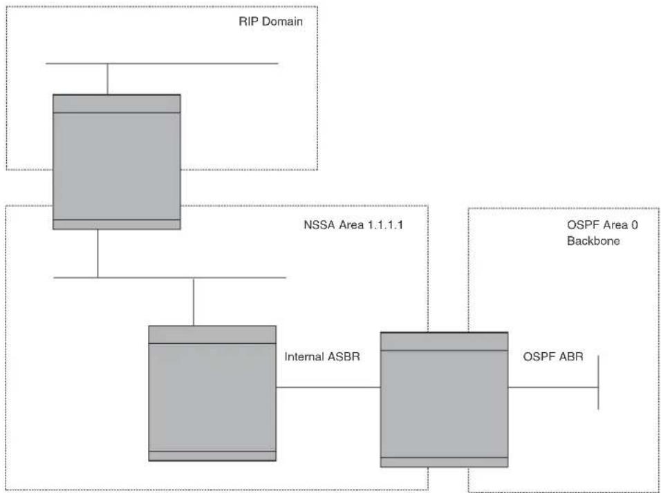
flowchart
graph TD
A["RIP Domain"] --> B["NSSA Area 1.1.1.1"]
B --> C["Internal ASBR"]
B --> D["OSPF ABR"]
D --> E["OSPF Area 0 Backbone"]
This example shows two routing domains, a RIP domain and an OSPF domain. The ASBR inside the NSSA imports external routes from RIP into the NSSA as Type-7 LSAs, which the ASBR floods throughout the NSSA.
The ABR translates the Type-7 LSAs into Type-5 LSAs. If an area range is configured for the NSSA, the ABR also summarizes the LSAs into an aggregate LSA before flooding the Type-5 LSAs into the backbone.
Since the NSSA is partially “stubby” the ABR does not flood external LSAs from the backbone into the NSSA. To provide access to the rest of the Autonomous System (AS), the ABR generates a default Type-7 LSA into the NSSA.
Configuring an NSSA
To configure OSPF area 1.1.1.1 as an NSSA, enter the following commands.
BigIron RX(config)# router ospf
BigIron RX(config-ospf-router)# area 1.1.1.1 nssa 1
BigIron RX(config-ospf-router)# write memory
Syntax: area
The
The nssa
NOTE
The BigIron RX does not inject the default route into an NSSA by default.
To configure additional parameters for OSPF interfaces in the NSSA, use the ip ospf area... command at the interface level of the CLI.
Configuring an address range for the NSSA
If you want the ABR that connects the NSSA to other areas to summarize the routes in the NSSA before translating them into Type-5 LSAs and flooding them into the other areas, configure an address range. The ABR creates an aggregate value based on the address range. The aggregate value becomes the address that the ABR advertises instead of advertising the individual addresses represented by the aggregate. You can configure up to 32 ranges in an OSPF area.
To configure an address range in NSSA 1.1.1.1, enter the following commands. This example assumes that you have already configured NSSA 1.1.1.1.
BigIron RX(config)# router ospf
BigIron RX(config-ospf-router)# area 1.1.1.1 range 209.157.22.1 255.255.0.0
BigIron RX(config-ospf-router)# write memory
Syntax: [no] area
The
The range
The
The advertise | not-advertise parameter specifies whether you want the device to send type 3 LSAs for the specified range in this area. The default is advertise.
Assigning an area range (optional)
You can assign a range for an area, but it is not required. Ranges allow a specific IP address and mask to represent a range of IP addresses within an area, so that only that reference range address is advertised to the network, instead of all the addresses within that range. Each area can have up to 32 range addresses.
To define an area range for subnets on 193.45.5.1 and 193.45.6.2, enter the following command.
BigIron RX(config)# router ospf
BigIron RX(config-ospf-router)# area 192.45.5.1 range 193.45.0.0 255.255.0.0
BigIron RX(config-ospf-router)# area 193.45.6.2 range 193.45.0.0 255.255.0.0
The range
The
Assigning interfaces to an area
Once you define OSPF areas, you can assign interfaces to the areas. All router ports must be assigned to one of the defined areas on an OSPF router. When a port is assigned to an area, all corresponding subnets on that port are automatically included in the assignment.
To assign interface 1/8 of Router A to area 192.5.0.0 and then save the changes, enter the following commands.
RouterA(config-ospf-router)# interface e 1/8
RouterA(config-if-e10000-1/8)# ip ospf area 192.5.0.0
RouterA(config-if-e10000-1/8)# write memory
Modify interface defaults
OSPF has interface parameters that you can configure. For simplicity, each of these parameters has a default value. No change to these default values is required except as needed for specific network configurations.
Port default values can be modified using the following CLI commands at the interface configuration level of the CLI:
- ip ospf area
- ip ospf auth-change-wait-time
- ip ospf authentication-key [0 | 1]
- ip ospf cost
-
ip ospf dead-interval
-
ip ospf hello-interval
- ip ospf md5-authentication key-activation-wait-time
| key-id [0 | 1] key - ip ospf passive
- ip ospf priority
- ip ospf retransmit-interval
- ip ospf transmit-delay
For a complete description of these parameters, see the summary of OSPF port parameters in the next section.
OSPF interface parameters
The following parameters apply to OSPF interfaces
| Area Assigns an interface to a specific area. You can assign either an IP address or number to represent an OSPF Area ID. If you assign a number, it can be any value from 0 - 2,147,483,647. |
| Auth-change-wait-time OSPF gracefully implements authentication changes to allow all routers to implement the change and thus prevent disruption to neighbor adjacencies. During the authentication-change interval, both the old and new authentication information is supported. The default authentication-change interval is 300 seconds (5 minutes). You change the interval to a value from 0 - 14400 seconds. |
| Authentication-key OSPF supports three methods of authentication for each interface—none, simple password, and MD5. Only one method of authentication can be active on an interface at a time. The default authentication value is none, meaning no authentication is performed.The simple password method of authentication requires you to configure an alphanumeric password on an interface. The simple password setting takes effect immediately. All OSPF packets transmitted on the interface contain this password. Any OSPF packet received on the interface is checked for this password. If the password is not present, then the packet is dropped. The password can be up to eight characters long.The MD5 method of authentication requires you to configure a key ID and an MD5 Key. The key ID is a number from 1 - 255 and identifies the MD5 key that is being used. The MD5 key can be up to sixteen alphanumeric characters long. |
| Cost Indicates the overhead required to send a packet across an interface. You can modify the cost to differentiate between 100 Mbps, 1Gbps, and 10 Gbps. The default cost is calculated by dividing 100 million by the bandwidth. For 10 Mbps links, the cost is 10. The cost for 100 Mbps, 1Gbps, and 10 Gbps links is 1, because the speed of 100 Mbps and 10Gbps was not in use at the time the OSPF cost formula was devised. |
| Dead-interval Indicates the number of seconds that a neighbor router waits for a hello packet from the current router before declaring the router down. The value can be from 1 - 65535 seconds. By default, the dead timer interval is four times the hello timer interval. The default is 40 seconds. |
| Hello-interval Represents the length of time between the transmission of hello packets. The value can be from 1 - 65535 seconds. The default is 10 seconds. On NBMA, the default is 30 seconds. |
| MD5-authentication activation wait time | The number of seconds the device waits until placing a new MD5 key into effect. The wait time provides a way to gracefully transition from one MD5 key to another without disturbing the network. The wait time can be from 0 - 14400 seconds. The default is 300 seconds (5 minutes). |
| MD5-authentication key ID and key | A method of authentication that requires you to configure a key ID and an MD5 key. The key ID is a number from 1 - 255 and identifies the MD5 key that is being used. The MD5 key consists of up to 16 alphanumeric characters. The MD5 is encrypted and included in each OSPF packet transmitted. |
| Passive When you configure an OSPF interface to be passive, that interface does not send or receive OSPF route updates. By default, all OSPF interfaces are active and thus can send and receive OSPF route information. Since a passive interface does not send or receive route information, the interface is in effect a stub network. OSPF interfaces are active by default.NOTE: This option affects all IP subnets configured on the interface. If you want to disable OSPF updates only on some of the IP subnets on the interface, use the ospf-ignore or ospf-passive parameter with the ip address command. Refer to “Assigning an IP address to an Ethernet port” on page 162. | |
| Priority Allows you to modify the priority of an OSPF router. The priority is used when selecting the designated router (DR) and backup designated routers (BDRs). The value can be from 0 - 255. The default is 1. If you set the priority to 0, the device does not participate in DR and BDR election. | |
| Retransmit-interval The time between retransmissions of link-state advertisements (LSAs) to adjacent routers for this interface. The value can be from 0 - 3600 seconds. The default is 5 seconds. | |
| Transit-delay The time it takes to transmit Link State Update packets on this interface.The value can be from 0 - 3600 seconds. The default is 1 second. | |
Encrypted display of the authentication string or MD5 authentication key
The Brocade implementation of OSPF authentication is based on RFC 2328. The optional 0 | 1 parameter with the authentication-key and md5-authentication key-id parameters affects encryption.
For added security, the device encrypts display of the password or authentication string. Encryption is enabled by default. The software also provides an optional parameter to disable encryption of a password or authentication string, on an individual OSPF area or OSPF interface basis.
When encryption of the passwords or authentication strings is enabled, they are encrypted in the CLI regardless of the access level you are using. The encryption option can be omitted (the default) or can be one of the following:
- 0 – Disables encryption for the password or authentication string you specify with the command. The password or string is shown as clear text in the running configuration and the startup configuration file. Use this option if you do not want display of the password or string to be encrypted.
- 1 – Assumes that the password or authentication string you enter is the encrypted form, and decrypts the value before using it.
NOTE
If you want the software to assume that the value you enter is the clear-text form, and to encrypt display of that form, do not enter 0 or 1. Instead, omit the encryption option and allow the software to use the default behavior.
If you specify encryption option 1, the software assumes that you are entering the encrypted form of the password or authentication string. In this case, the software decrypts the password or string you enter before using the value for authentication. If you accidentally enter option 1 followed by the clear-text version of the password or string, authentication will fail because the value used by the software will not match the value you intended to use.
Change the timer for OSPF authentication changes
When you make an OSPF authentication change, the software uses the authentication-change timer to gracefully implement the change. The software implements the change in the following ways:
- Outgoing OSPF packets – After you make the change, the software continues to use the old authentication to send packets, during the remainder of the current authentication-change interval. After this, the software uses the new authentication for sending packets.
- Inbound OSPF packets – The software accepts packets containing the new authentication and continues to accept packets containing the older authentication for two authentication-change intervals. After the second interval ends, the software accepts packets only if they contain the new authentication key.
The default authentication-change interval is 300 seconds (5 minutes). You change the interval to a value from 0 - 14400 seconds.
OSPF provides graceful authentication change for all the following types of authentication changes in OSPF:
- Changing authentication methods from one of the following to another of the following:
- Simple text password
- MD5 authentication
- No authentication
- Configuring a new simple text password or MD5 authentication key
- Changing an existing simple text password or MD5 authentication key
To change the authentication-change interval, enter a command such as the following at the interface configuration level of the CLI.
BigIron RX(config-if-e10000-2/5)# ip ospf auth-change-wait-time 400
Syntax: [no] ip ospf auth-change-wait-time
The
NOTE
For backward compatibility, the ip ospf md5-authentication key-activation-wait-time
Block flooding of outbound LSAs on specific OSPF interfaces
By default, the device floods all outbound LSAs on all the OSPF interfaces within an area. You can configure a filter to block outbound LSAs on an OSPF interface. This feature is particularly useful when you want to block LSAs from some, but not all, of the interfaces attached to the area.
After you apply filters to block the outbound LSAs, the filtering occurs during the database synchronization and flooding.
If you remove the filters, the blocked LSAs are automatically re-flooded. You do not need to reset OSPF to re-flood the LSAs.
NOTE
You cannot block LSAs on virtual links.
To apply a filter to an OSPF interface to block flooding of outbound LSAs on the interface, enter the following command at the Interface configuration level for that interface.
BigIron RX(config-if-e10000-1/1)# ip ospf database-filter all out
The command in this example blocks all outbound LSAs on the OSPF interface configured on port 1/1.
Syntax: [no] ip ospf database-filter all out
To remove the filter, enter a command such as the following.
BigIron RX(config-if-e10000-1/1)# no ip ospf database-filter all out
Assign virtual links
All ABRs (area border routers) must have either a direct or indirect link to the OSPF backbone area (0.0.0.0 or 0). If an ABR does not have a physical link to the area backbone, the ABR can configure a virtual link to another router within the same area, which has a physical connection to the area backbone.
The path for a virtual link is through an area shared by the neighbor ABR (router with a physical backbone connection), and the ABR requiring a logical connection to the backbone.
Two parameters fields must be defined for all virtual links—transit area ID and neighbor router:
- The transit area ID represents the shared area of the two ABRs and serves as the connection point between the two routers. This number should match the area ID value.
- The neighbor router field is the router ID (IP address) of the router that is physically connected to the backbone, when assigned from the router interface requiring a logical connection. When assigning the parameters from the router with the physical connection, the router ID is the IP address of the router requiring a logical connection to the backbone.
NOTE
By default, the Brocade router ID is the IP address configured on the lowest numbered loopback interface. If the device does not have a loopback interface, the default router ID is the lowest numbered IP address configured on the device. For more information or to change the router ID, refer to “Changing the router ID” on page 182.
NOTE
When you establish an area virtual link, you must configure it on both of the routers (both ends of the virtual link).
FIGURE 106 Defining OSPF virtual links within a network

flowchart
graph TD
A["OSPF Area 0"] --> B["BiglronC\nRouter ID 209.157.22.1"]
B --> C["OSPF Area 1\n"transit area""]
C --> D["BiglronB"]
D --> E["OSPF Area 2"]
E --> F["BiglronA\nRouter ID 10.0.0.1"]
Figure 106 shows an OSPF area border router, BigIron RXA, that is cut off from the backbone area (area 0). To provide backbone access to BigIron RXA, you can add a virtual link between BigIron RXA and BigIron RXC using area 1 as a transit area. To configure the virtual link, you define the link on the router that is at each end of the link. No configuration for the virtual link is required on the routers in the transit area.
To define the virtual link on BigIron RXA, enter the following commands.
BigIron RXA(config)#router ospf
BigIron RXA(config-ospf-router)# area 2
BigIron RXA(config-ospf-router)# area 1
BigIron RXA(config-ospf-router)# area 1 virtual-link 209.157.22.1
BigIron RXA(config-ospf-router)# write memory
Enter the following commands to configure the virtual link on BigIron RXC.
BigIron RXC(config)#router ospf
BigIron RXC(config-ospf-router)# area 0
BigIron RXC(config-ospf-router)# area 1
BigIron RXC(config-ospf-router)# area 1 virtual-link 10.0.0.1
Syntax: [no] area <ip-addr> | <num> virtual-link <router-id>
[authentication-key | dead-interval | hello-interval | retransmit-interval | transmit-delay <value> |
[md5-authentication key-activation-wait-time <num> | key-id <num> [0 | 1] key <string>]
The area
The
Refer to "Modify virtual link parameters" on page 697 for descriptions of the optional parameters.
Modify virtual link parameters
OSPF has some parameters that you can modify for virtual links. Notice that these are the same parameters as the ones you can modify for physical interfaces.
You can modify default values for virtual links using the following CLI command at the OSPF router level of the CLI, as shown in the following syntax.
Syntax: [no] area <num> | <ip-addr> virtual-link <ip-addr> [authentication-key [0 | 1] <string>]
[dead-interval <num>]
[hello-interval <num>] [md5-authentication key-activation-wait-time <num> | key-id <num> [0 | 1] key <string>]
[retransmit-interval <num>] [transmit-delay <num>]
The parameters are described below.
Virtual link parameter descriptions
You can modify the following virtual link interface parameters.
| Authentication Key This parameter allows you to assign different authentication methods on a port-by-port basis. OSPF supports three methods of authentication for each interface—none, simple password, and MD5. Only one method of authentication can be active on an interface at a time.The simple password method of authentication requires you to configure an alphanumeric password on an interface. The password can be up to eight characters long. The simple password setting takes effect immediately. All OSPF packets transmitted on the interface contain this password. All OSPF packets received on the interface are checked for this password. If the password is not present, then the packet is dropped.The MD5 method of authentication encrypts the authentication key you define. The authentication is included in each OSPF packet transmitted. |
| MD5 Authentication Key When simple authentication is enabled, the key is an alphanumeric password of up to eight characters. When MD5 is enabled, the key is an alphanumeric password of up to 16 characters that is later encrypted and included in each OSPF packet transmitted. You must enter a password in this field when the system is configured to operate with either simple or MD5 authentication. |
| MD5 Authentication Key ID The Key ID is a number from 1 - 255 and identifies the MD5 key that is being used. This parameter is required to differentiate among multiple keys defined on a router. |
| MD5 Authentication Wait Time This parameter determines when a newly configured MD5 authentication key is valid. This parameter provides a graceful transition from one MD5 key to another without disturbing the network. All new packets transmitted after the key activation wait time interval use the newly configured MD5 Key. OSPF packets that contain the old MD5 key are accepted for up to five minutes after the new MD5 key is in operation.The range for the key activation wait time is from 0 – 14400 seconds. The default value is 300 seconds. |
| Hello Interval The length of time between the transmission of hello packets. The range is 1 – 65535 seconds. The default is 10 seconds. On NBMA, the default is 30 seconds. |
| Retransmit Interval The interval between the re-transmission of link state advertisements to router adjacencies for this interface. The range is 0 – 3600 seconds. The default is 5 seconds. |
| Transmit Delay The period of time it takes to transmit Link State Update packets on the interface. The range is 0 – 3600 seconds. The default is 1 second. |
Configuring an OSPF non-broadcast interface
OSPF routers generally use broadcast packets to establish neighbor relationships and broadcast route updates on Ethernet and virtual routing interfaces (ves). Beginning with Biglon RX software releases 02.3.00, you can configure an interface to send OSPF unicast packets rather than broadcast packets to its neighbor by configuring non-broadcast multi-access (NBMA) networks.
NBMA networks are similar to broadcast networks except the packets are sent as unicast. This type of network can be useful in situations where multicast traffic is not feasible (for example when a firewall does not allow multicast packets).
You configure NBMAs on an interface. The routers at the other end of that interface must have a non-broadcast neighbor configured. There is no restriction on the number of routers sharing a non-broadcast interface (for example, through a hub or switch).
To configure NBMA on an interface, do the following.
- Create an OSPF area on an interface, then enable NBMA on that interface.
BigIron RX(config)# int ve 20
BigIron RX(config-vif-20)# ip ospf area 0
BigIron RX(config-vif-20)# ip ospf network non-broadcast
BigIron RX(config-vif-20)# exit
Syntax: [no] ip ospf network non-broadcast
- Then under the router OSPF level, specify the IP address of the neighbor in the OSPF configuration. The non-broadcast interface configuration must be done on the OSPF routers on both ends of the link.
For example, the following commands configure VE 20 as a non-broadcast interface.
The following commands specify 1.1.20.1 as an OSPF neighbor address. The address specified must be in the same sub-net as a non-broadcast interface.
BigIron RX(config)# router ospf
BigIron RX(config-ospf-router)# neighbor 1.1.20.1
Syntax: neighbor
For example, to configure the feature in a network with three routers connected by a hub or switch, each router must have the linking interface configured as a non-broadcast interface, and both of the other routers must be specified as neighbors.
The output of the show ip ospf interface command has been enhanced to display information about non-broadcast interfaces and neighbors that are configured in the same sub-net.
For example.
BigIron RX# show ip ospf interface
v20,OSPF enabled
IP Address 1.1.20.4, Area 0
OSPF state BD, Pri 1, Cost 1, Options 2, Type nbma Events 6
Timers(sec): Transit 1, Retrans 5, Hello 10, Dead 40
DR: Router ID 1.1.13.1 Interface Address 1.1.20.5
BDR: Router ID 2.2.2.1 Interface Address 1.1.20.4
Neighbor Count = 1, Adjacent Neighbor Count= 2
Non-broadcast neighbor config: 1.1.20.1, 1.1.20.2, 1.1.20.3, 1.1.20.5,
Neighbor: 1.1.20.5
Authentication-Key:None
MD5 Authentication: Key None, Key-Id None, Auth-change-wait-time 300
In the Type field, “non-broadcast” indicates that this is a non-broadcast interface. When the interface type is non-broadcast, the Non-broadcast neighbor config field displays the neighbors that are configured in the same sub-net. If no neighbors are configured in the same sub-net, a message such as the following is displayed.
***Warning! no non-broadcast neighbor config in 1.1.100.1 255.255.255.0
OSPF point-to-point links
In an OSPF point-to-point network, where a direct Layer 3 connection exists between a single pair of OSPF routers, there is no need for Designated and Backup Designated Routers, as is the case in OSPF multi-access networks. Without the need for Designated and Backup Designated routers, a point-to-point network establishes adjacency and converges faster. The neighboring routers become adjacent whenever they can communicate directly. In contrast, in broadcast and non-broadcast multi-access (NBMA) networks, the Designated Router and Backup Designated Router become adjacent to all other routers attached to the network.
NOTE
This feature is supported on Gigabit Ethernet and 10-Gigabit Ethernet interfaces.
NOTE
This feature is supported on physical interfaces. It is not supported on virtual interfaces.
NOTE
Brocade supports numbered point-to-point networks, meaning the OSPF router must have an IP interface address which uniquely identifies the router over the network. Brocade does not support unnumbered point-to-point networks.
Configuring an OSPF point-to-point link
To configure an OSPF point-to-point link, enter commands such as the following.
BigIron RX(config)# interface eth 1/5
BigIron RX(config-if-1/5)# ip ospf network point-to-point
This command configures an OSPF point-to-point link on Interface 5 in slot 1.
Syntax: [no] ip ospf network point-to-point
Viewing configured OSPF point-to-point links
You can use the show ip ospf interface command to display OSPF point-to-point information. Enter the following command at any CLI level.
BigIron RX# show ip ospf interface 192.168.1.1
IP Address 192.168.1.1, Area 0
OSPF state ptr2ptr, Pri 1, Cost 1, Options 2, Type pt-2-pt Events 1
Timers(sec): Transit 1, Retrans 5, Hello 10, Dead 40
DR: Router ID 0.0.0.0 Interface Address 0.0.0.0
BDR: Router ID 0.0.0.0 Interface Address 0.0.0.0
Neighbor Count = 0, Adjacent Neighbor Count= 1
Neighbor: 2.2.2.2
Authentication-Key: None
MD5 Authentication: Key None, Key-Id None, Auth-change-wait-time 300
Syntax: show ip ospf interface [
The
The following table defines the highlighted fields shown in the above example output of the show ip ospf interface command.
TABLE 109 Output of the show ip ospf interface command
| This field Displays |
| IP Address The IP address of the interface. |
| OSPF state ptr2ptr (point to point) |
| Pri The link ID as defined in the router-LSA. This value can be one of the following.1 = point-to-point link3 = point-to-point link with an assigned subnet |
| Cost The configured output cost for the interface. |
Options OSPF Options (Bit7 - Bit0):
- unused:1
- opaque:1
- summary:1
- dont_propagate:1
- nssa:1
- multicast:1
- externals:1
- tos:1
TABLE 109 Output of the show ip ospf interface command
| This field Displays | |
| Type The area type, which can be one of the following: | |
| • Broadcast = 0x01 | |
| • NBMA = 0x02 | |
| • Point to Point = 0x03 | |
| • Virtual Link = 0x04 | |
| • Point to Multipoint = 0x05 | |
| Events OSPF Interface Event: | |
| • Interface_Up = 0x00 | |
| • Wait_Timer = 0x01 | |
| • Backup_Seen = 0x02 | |
| • Neighbor_Change = 0x03 | |
| • Loop_Indication = 0x04 | |
| • Unloop_Indication = 0x05 | |
| • Interface_Down = 0x06 | |
| • Interface_Passive = 0x07 | |
| Adjacent Neighbor Count The number of adjacent neighbor routers. | |
| Neighbor The neighbor router's ID. | |
Encrypted display of the authentication string or MD5 authentication key
The optional 0 | 1 parameter with the authentication-key and md5-authentication key-id parameters affects encryption.
For added security, the device encrypts the display of the password or authentication string. Encryption is enabled by default. The software also provides an optional parameter to disable encryption of a password or authentication string, on an individual OSPF area or OSPF interface basis.
When encryption of the passwords or authentication strings is enabled, they are encrypted in the CLI regardless of the access level you are using. The encryption option can be omitted (the default) or can be one of the following:
- 0 - Disables encryption for the password or authentication string you specify with the command. The password or string is shown as clear text in the running configuration and the startup configuration file. Use this option of you do not want display of the password or string to be encrypted.
- 1 - Assumes that the password or authentication string you enter is the encrypted form, and decrypts the value before using it.
NOTE
If you want the software to assume that the value you enter is the clear-text form, and to encrypt display of that form, do not enter 0 or 1. Instead, omit the encryption option and allow the software to use the default behavior.
If you specify encryption option 1, the software assumes that you are entering the encrypted form of the password or authentication string. In this case, the software decrypts the password or string you enter before using the value for authentication. If you accidentally enter option 1 followed by the clear-text version of the password or string, authentication will fail because the value used by the software will not match the value you intended to use.
Changing the reference bandwidth for the cost on OSPF interfaces
Each interface on which OSPF is enabled has a cost associated with it. The device advertises its interfaces and their costs to OSPF neighbors. For example, if an interface has an OSPF cost of ten, the device advertises the interface with a cost of ten to other OSPF routers.
By default, an interface's OSPF cost is based on the port speed of the interface. The cost is calculated by dividing the reference bandwidth by the port speed. The default reference bandwidth is 100 Mbps, which results in the following default costs:
- 10 Mbps port - 10
- All other port speeds - 1
You can change the reference bandwidth, to change the costs calculated by the software.
The software uses the following formula to calculate the cost:
Cost = reference-bandwidth/interface-speed
If the resulting cost is less than 1, the software rounds the cost up to 1. The default reference bandwidth results in the following costs:
• 10 Mbps port's cost = 100/10 = 10
• 100 Mbps port's cost = 100/100 = 1
- 1000 Mbps port's cost = 100/1000 = 0.10, which is rounded up to 1
- 10 Gbps port's cost = 100/10000 = 0.01, which is rounded up to 1
The bandwidth for interfaces that consist of more than one physical port is calculated as follows:
- Trunk group – The combined bandwidth of all the ports.
- Virtual interface – The combined bandwidth of all the ports in the port-based VLAN that contains the virtual interface.
The default reference bandwidth is 100 Mbps. You can change the reference bandwidth to a value from 1 - 4294967.
If a change to the reference bandwidth results in a cost change to an interface, the device sends a link-state update to update the costs of interfaces advertised by the device.
NOTE
If you specify the cost for an individual interface, the cost you specify overrides the cost calculated by the software.
Interface types to which the reference bandwidth does not apply
Some interface types are not affected by the reference bandwidth and always have the same cost regardless of the reference bandwidth in use:
- The cost of a loopback interface is always 1.
- The cost of a virtual link is calculated using the Shortest Path First (SPF) algorithm and is not affected by the auto-cost feature.
Changing the reference bandwidth
To change the reference bandwidth, enter a command such as the following at the OSPF configuration level of the CLI:
BigIron RX(config-ospf-router)# auto-cost reference-bandwidth 500
The reference bandwidth specified in this example results in the following costs:
• 10 Mbps port's cost = 500/10 = 50
• 100 Mbps port's cost = 500/100 = 5
- 1000 Mbps port's cost = 500/1000 = 0.5, which is rounded up to 1
The costs for 10 Mbps and 100 Mbps ports change as a result of the changed reference bandwidth. Costs for higher-speed interfaces remain the same.
Syntax: [no] auto-cost reference-bandwidth
The
To restore the reference bandwidth to its default value and thus restore the default costs of interfaces to their default values, enter the following command.
BigIron RX(config-ospf-router)# no auto-cost reference-bandwidth
Define redistribution filters
Route redistribution imports and translates different protocol routes into a specified protocol type. On the BigIron RX, redistribution is supported for static routes, ISIS, OSPF, RIP, and BGP4. OSPF redistribution supports the import of static, ISIS, RIP, and BGP4 routes into OSPF routes.
NOTE
The BigIron RX advertises the default route into OSPF even if redistribution is not enabled, and even if the default route is learned through an IBGP neighbor. IBGP routes (including the default route) are not redistributed into OSPF by OSPF redistribution (for example, by the OSPF redistribute command).
In Figure 107 on page 704, an administrator wants to configure the BigIron RX acting as the ASBR (Autonomous System Boundary Router) between the RIP domain and the OSPF domain to redistribute routes between the two domains.
NOTE
The ASBR must be running both RIP and OSPF protocols to support this activity.
FIGURE 107 Redistributing OSPF and static routes to RIP routes

flowchart
graph TD
A["RIP Domain"] --> B["ASBR (Autonomous System Border Router)"]
B --> C["OSPF Domain"]
style A fill:#ccc,stroke:#333
style B fill:#ccc,stroke:#333
style C fill:#ccc,stroke:#333
You also have the option of specifying import of just ISIS, RIP, OSPF, BGP4, or static routes, as well as specifying that only routes for a specific network or with a specific cost (metric) be imported, as shown in the command syntax below:
Syntax: [no] redistribution bgp | connected | rip | static [route-map
For example, to enable redistribution of RIP and static IP routes into OSPF, enter the following commands.
BigIron RX(config)# router ospf
BigIron RX(config-ospf-router)# redistribution rip
BigIron RX(config-ospf-router)# redistribution static
BigIron RX(config-ospf-router)# write memory
Modify default metric for redistribution
The default metric is a global parameter that specifies the cost applied to all OSPF routes by default. The default value is 10. You can assign a cost from 1 - 65535.
NOTE
You also can define the cost on individual interfaces. The interface cost overrides the default cost.
To assign a default metric of 4 to all routes imported into OSPF, enter the following commands.
BigIron RX(config)# router ospf
BigIron RX(config-ospf-router)# default-metric 4
Syntax: default-metric
The
Enable route redistribution
NOTE
Do not enable redistribution until you have configured the redistribution route map. Otherwise, you might accidentally overload the network with routes you did not intend to redistribute.
To enable redistribution of RIP and static IP routes into OSPF, enter the following commands.
BigIron RX(config)# router ospf
BigIron RX(config-ospf-router)# redistribution rip
BigIron RX(config-ospf-router)# redistribution static
BigIron RX(config-ospf-router)# write memory
Example using a route map
To configure a route map and use it for redistribution of routes into OSPF, enter commands such as the following.
BigIron RX(config)# ip route 1.1.0.0 255.255.0.0 207.95.7.30
BigIron RX(config)# ip route 1.2.0.0 255.255.0.0 207.95.7.30
BigIron RX(config)# ip route 1.3.0.0 255.255.0.0 207.95.7.30
BigIron RX(config)# ip route 4.1.0.0 255.255.0.0 207.95.6.30
BigIron RX(config)# ip route 4.2.0.0 255.255.0.0 207.95.6.30
BigIron RX(config)# ip route 4.3.0.0 255.255.0.0 207.95.6.30
BigIron RX(config)# ip route 4.4.0.0 255.255.0.0 207.95.6.30 5
BigIron RX(config)# route-map abc permit 1
BigIron RX(config-routemap abc)# match metric 5
BigIron RX(config-routemap abc)# set metric 8
BigIron RX(config-routemap abc)# router ospf
BigIron RX(config-ospf-router)# redistribute static route-map abc
The commands in this example configure some static IP routes, then configure a route map and use the route map for redistributing static IP routes into OSPF.
The ip route commands configure the static IP routes. The route-map command begins configuration of a route map called "abc". The number indicates the route map entry (called the "instance") you are configuring. A route map can contain multiple entries. The software compares routes to the route map entries in ascending numerical order and stops the comparison once a match is found.
The match command in the route map matches on routes that have 5 for their metric value (cost). The set command changes the metric in routes that match the route map to 8.
The redistribute static command enables redistribution of static IP routes into OSPF, and uses route map "abc" to control the routes that are redistributed. In this example, the route map allows a static IP route to be redistributed into OSPF only if the route has a metric of 5, and changes the metric to 8 before placing the route into the OSPF route table.
The following command shows the result of the redistribution. Since only one of the static IP routes configured above matches the route map, only one route is redistributed. Notice that the route's metric is 5 before redistribution but is 8 after redistribution.
BigIron RX(config-ospf-router)# show ip ospf database external
| Index | Aging | LS ID | Router | Netmask | Metric | Flag |
| 1 | 2 | 4.4.0.0 | 10.10.10.60 | ffff0000 | 80000008 | 0000 |
Syntax: [no] redistribution bgp | connected | [rip] | [isis level-1| level-1-2| level-2] | [static [route-map
The bgp | connected | rip | isis | static parameter specifies the route source.
The route-map
- match ip address | next-hop
- match metric
- match tag
The following set parameters are valid for OSPF redistribution:
- set ip next hop
- set metric [+ | - ]
| none - set metric-type type-1 | type-2
- set tag
NOTE
You must configure the route map before you configure a redistribution that uses the route map.
NOTE
When you use a route map for route redistribution, the software disregards the permit or deny action of the route map.
NOTE
For an external route that is redistributed into OSPF through a route map, the metric value of the route remains the same unless the metric is set by a set metric command inside the route map. The default-metric
Disable or re-enable load sharing
The device can load share among up to eight equal-cost IP routes to a destination. By default, IP load sharing is enabled. The default is 4 equal-cost paths but you can specify from 2 - 8 paths.
The router software can use the route information it learns through OSPF to determine the paths and costs. Figure 108 shows an example of an OSPF network containing multiple paths to a destination (in this case, R1).
FIGURE 108 Example OSPF network with four equal-cost paths
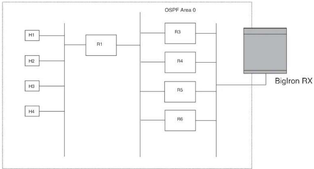
flowchart
graph LR
H1 --> R1
H2 --> R1
H3 --> R1
H4 --> R1
R1 --> R3
R1 --> R4
R1 --> R5
R1 --> R6
R3 --> BigIron RX
R4 --> BigIron RX
R5 --> BigIron RX
R6 --> BigIron RX
In the example in Figure 108, the BigIron RX has four paths to R1:
- BigIron RX ->R3
- BigIron RX ->R4
- BigIron RX ->R5
- BigIron RX ->R6
Normally, the BigIron RX will choose the path to the R1 with the lower metric. For example, if R3's metric is 1400 and R4's metric is 600, the BigIron RX will always choose R4.
However, suppose the metric is the same for all four routers in this example. If the costs are the same, the router now has four equal-cost paths to R1. To allow the router to load share among the equal cost routes, enable IP load sharing. The software supports four equal-cost OSPF paths by default when you enable load sharing. You can specify from 2 - 8 paths.
NOTE
The BigIron RX is not source routing in these examples. The router is concerned only with the paths to the next-hop routers, not the entire paths to the destination hosts.
OSPF load sharing is enabled by default when IP load sharing is enabled. To configure IP load sharing parameters, refer to "Configuring IP load sharing" on page 209.
Configure external route summarization
When the BigIron RX is an OSPF Autonomous System Boundary Router (ASBR), you can configure it to advertise one external route as an aggregate for all redistributed routes that are covered by a specified address range.
When you configure an address range, the range takes effect immediately. All the imported routes are summarized according to the configured address range. Imported routes that have already been advertised and that fall within the range are flushed out of the AS and a single route corresponding to the range is advertised.
If a route that falls within a configured address range is imported by the device, no action is taken if the device has already advertised the aggregate route; otherwise the device advertises the aggregate route. If an imported route that falls with in a configured address range is removed by the device, no action is taken if there are other imported routes that fall with in the same address range; otherwise the aggregate route is flushed.
You can configure up to 32 address ranges. The device sets the forwarding address of the aggregate route to zero and sets the tag to zero.
If you delete an address range, the advertised aggregate route is flushed and all imported routes that fall within the range are advertised individually.
If an external LSDB overflow condition occurs, all aggregate routes are flushed out of the AS, along with other external routes. When the device exits the external LSDB overflow condition, all the imported routes are summarized according to the configured address ranges.
NOTE
If you use redistribution filters in addition to address ranges, the BigIron RX applies the redistribution filters to routes first, then applies them to the address ranges.
NOTE
If you disable redistribution, all the aggregate routes are flushed, along with other imported routes.
NOTE
This option affects only imported, type 5 external routes. A single type 5 LSA is generated and flooded throughout the AS for multiple external routes. Type 7-route redistribution is not affected by this feature. All type 7 routes will be imported (if redistribution is enabled). To summarize type 7 LSAs or exported routes, use NSSA address range summarization.
To configure a summary address for OSPF routes, enter commands such as the following.
BigIron RX(config-ospf-router)# summary-address 10.1.0.0 255.255.0.0
The command in this example configures summary address 10.1.0.0, which includes addresses 10.1.1.0, 10.1.2.0, 10.1.3.0, and so on. For all of these networks, only the address 10.1.0.0 is advertised in external LSAs.
Syntax: summary-address
The
The
To display the configured summary addresses, enter the following command at any level of the CLI.
BigIron RX(config-ospf-router)# show ip ospf config OSPF Redistribution Address Ranges currently defined:
| Range-Address | Subnetmask |
| 1.0.0.0 | 255.0.0.0 |
| 1.0.1.0 | 255.255.255.0 |
| 1.0.2.0 | 255.255.255.0 |
Syntax: show ip ospf config
Configure default route origination
When the BigIron RX is an OSPF Autonomous System Boundary Router (ASBR), you can configure it to automatically generate a default external route into an OSPF routing domain. This feature is called “default route origination” or “default information origination”.
By default, the BigIron RX does not advertise the default route into the OSPF domain. If you want the BigIron RX to advertise the OSPF default route, you must explicitly enable default route origination.
When you enable OSPF default route origination, the BigIron RX advertises a type 5 default route that is flooded throughout the AS (except stub areas and NSSAs). In addition, internal NSSA ASBRs advertise their default routes as translatable type 7 default routes.
The BigIron RX advertises the default route into OSPF even if OSPF route redistribution is not enabled, and even if the default route is learned through an IBGP neighbor.
NOTE
BigIron RX never advertises the OSPF default route, regardless of other configuration parameters, unless you explicitly enable default route origination using the following method.
If the BigIron RX is an ASBR, you can use the "always" option when you enable the default route origination. The always option causes the ASBR to create and advertise a default route if it does not already have one configured.
If default route origination is enabled and you disable it, the default route originated by the BigIron RX is flushed. Default routes generated by other OSPF routers are not affected. If you re-enable the feature, the feature takes effect immediately and thus does not require you to reload the software.
NOTE
The ABR (BigIron RX) will not inject the default route into an NSSA by default and the command described in this section will not cause the BigIron RX to inject the default route into the NSSA. To inject the default route into an NSSA, use the area
To enable default route origination, enter the following command.
BigIron RX(config-ospf-router)# default-information-originate
To disable the feature, enter the following command.
BigIron RX(config-ospf-router)# no default-information-originate
Syntax: [no default-information-originate [always] [metric
The always parameter advertises the default route regardless of whether the router has a default route. This option is disabled by default.
The metric
The metric-type
• 1 - Type 1 external route
- 2 - Type 2 external route
If you do not use this option, the default redistribution metric type is used for the route type.
NOTE
If you specify a metric and metric type, the values you specify are used even if you do not use the always option.
Configuring a default network route
The BigIron RX enables you to specify a candidate default route without the need to specify the next hop gateway. If the IP route table does not contain an explicit default route (for example, 0.0.0.0/0) or propagate an explicit default route through routing protocols, the software can use the default network route as a default route instead.
When the software uses the default network route, it also uses the default network route's next hop gateway as the gateway of last resort.
This feature is especially useful in environments where network topology changes can make the next hop gateway unreachable. This feature allows the BigIron RX to perform default routing even if the default network route's default gateway changes.
The feature thus differs from standard default routes. When you configure a standard default route, you also specify the next hop gateway. If a topology change makes the gateway unreachable, the default route becomes unusable.
For example, if you configure 10.10.10.0/24 as a candidate default network route, if the IP route table does not contain an explicit default route (0.0.0.0/0), the software uses the default network route and automatically uses that route's next hop gateway as the default gateway. If a topology change occurs and as a result the default network route's next hop gateway changes, the software can still use the default network route.
Configuring a default network route
You can configure up to four default network routes. To configure a default network route, enter commands such as the following.
BigIron RX(config)# ip default-network 209.157.22.0 BigIron RX(config)# write memory
Syntax: ip default-network
The
To verify that the route is in the route table, enter the following command at any level of the CLI.
| BigIron RX(config)# show ip route | ||||||
| Total number of IP routes: 2 | ||||||
| Start index: 1 B:BGP D:Connected R:RIP S:Static O:OSPF *:Candidate default | ||||||
| Destination | Gateway | Port | Cost | Type | ||
| 1 | 209.157.20.0 | 0.0.0.0 | lb1 | 1 | D | |
| 2 | 209.157.22.0 | 0.0.0.0 | 4/11 | 1 | *D | |
This example shows two routes. Both of the routes are directly attached, as indicated in the Type column. However, one of the routes is shown as type “*D”, with an asterisk (*). The asterisk indicates that this route is a candidate default network route.
Modify SPF timers
The BigIron RX uses the following timers when calculating the shortest path for OSPF routes:
- SPF delay – When the BigIron RX receives a topology change, the software waits before it starts a Shortest Path First (SPF) calculation. By default, the software waits 0 (zero) seconds. You can configure the SPF delay to a value from 0 – 65535 seconds. If you set the SPF delay to 0 seconds, the software immediately begins the SPF calculation after receiving a topology change.
- SPF hold time – The BigIron RX waits for a specific amount of time between consecutive SPF calculations. By default, the BigIron RX waits ten seconds. You can configure the SPF hold time to a value from 0 – 65535 seconds. If you set the SPF hold time to 0 seconds, the software does not wait between consecutive SPF calculations.
NOTE
OSPF incrementally updates the OSPF routing table when new Type-3 or Type-4 Summary, Type-5 External or Type-7 External NSSA LSAs are received.
You can set the delay and hold time to lower values to cause the BigIron RX to change to alternate paths more quickly in the event of a route failure. Note that lower values require more CPU processing time.
You can change one or both of the timers.
To change the SPF delay and hold time, enter commands such as the following.
BigIron RX(config-ospf-router)# timers spf 10 20
The command in this example changes the SPF delay to 10 seconds and changes the SPF hold time to 20 seconds.
Syntax: timers spf
The
The
To set the timers back to their default values, enter a command such as the following.
BigIron RX(config-ospf-router)# no timers spf 10 20
Modify redistribution metric type
The redistribution metric type is used by default for all routes imported into OSPF unless you specify different metrics for individual routes using redistribution filters. Type 2 specifies a big metric (three bytes). Type 1 specifies a small metric (two bytes). The default value is type 2.
To modify the default value to type 1, enter the following command.
BigIron RX(config-ospf-router)# metric-type type1
Syntax: metric-type type1 | type2
The default is type2.
Modify administrative distance
The BigIron RX can learn about networks from various protocols, including Border Gateway Protocol version 4 (BGP4), RIP, ISIS, and OSPF. Consequently, the routes to a network may differ depending on the protocol from which the routes were learned. The default administrative distance for OSPF routes is 110. Refer to “Changing administrative distances” on page 767 for a list of the default distances for all route sources.
The router selects one route over another based on the source of the route information. To do so, the router can use the administrative distances assigned to the sources. You can bias the device's decision by changing the default administrative distance for OSPF routes.
Configuring administrative distance based on route type
You can configure a unique administrative distance for each type of OSPF route. For example, you can use this feature to prefer a static route over an OSPF inter-area route but you also want to prefer OSPF intra-area routes to static routes.
The distance you specify influences the choice of routes when the device has multiple routes for the same network from different protocols. The device prefers the route with the lower administrative distance.
You can specify unique default administrative distances for the following route types:
- Intra-area routes
- Inter-area routes
- External routes
The default for all these OSPF route types is 110.
NOTE
This feature does not influence the choice of routes within OSPF. For example, an OSPF intra-area route is always preferred over an OSPF inter-area route, even if the intra-area route's distance is greater than the inter-area route's distance.
To change the default administrative distances for inter-area routes, intra-area routes, and external routes, enter the following command.
BigIron RX(config-ospf-router)# distance external 100
BigIron RX(config-ospf-router)# distance inter-area 90
BigIron RX(config-ospf-router)# distance intra-area 80
Syntax: distance external | inter-area | intra-area
The external | inter-area | intra-area parameter specifies the route type for which you are changing the default administrative distance.
The
To reset the administrative distance to its system default (110), enter a command such as the following.
BigIron RX(config-ospf-router)# no distance external 100
Configure OSPF group Link State Advertisement pacing
The BigIron RX paces LSA refreshes by delaying the refreshes for a specified time interval instead of performing a refresh each time an individual LSA's refresh timer expires. The accumulated LSAs constitute a group, which the BigIron RX refreshes and sends out together in one or more packets.
The pacing interval, which is the interval at which the device refreshes an accumulated group of LSAs, is configurable to a range from 10 - 1800 seconds (30 minutes). The default is 240 seconds (four minutes). Thus, every four minutes, the device refreshes the group of accumulated LSAs and sends the group together in the same packets.
Usage guidelines
The pacing interval is inversely proportional to the number of LSAs the device is refreshing and aging. For example, if you have approximately 10,000 LSAs, decreasing the pacing interval enhances performance. If you have a very small database (40 - 100 LSAs), increasing the pacing interval to 10 - 20 minutes might enhance performance slightly.
Changing the LSA pacing interval
To change the LSA pacing interval, use the following CLI method.
To change the LSA pacing interval to two minutes (120 seconds), enter the following command.
BigIron RX(config-ospf-router)# timers lsa-group-pacing 120
Syntax: [no] timers lsa-group-pacing
The
To restore the pacing interval to its default value, enter the following command.
BigIron RX(config-ospf-router)# no timers lsa-group-pacing
OSPF ABR type 3 LSA filtering
OSPF ABR Type 3 LSA filtering increases the ability of an ABR that is running the OSPF protocol to filter type 3 link-state advertisements (LSAs) that are sent between different OSPF areas. Only packets with specified prefixes will be sent from one area to another area and prohibits all packets with other prefixes.
Type 3 LSAs refer to summary links and are sent by ABRs to advertise destinations outside the area. OSPF ABR Type 3 LSA filtering gives the administrator improved control of route distribution between OSPF areas.
Usage and configuration guidelines
- The "area prefix-list" command is only applicable to the ABRs. If the router is not an ABR the configuration is accepted however it will start working only after router is made ABR.
-
With this feature enabled in the "in" direction, all type 3 LSAs originated by the ABR to this area, based on information from all other areas, are filtered by the prefix list. Type 3 LSAs that were originated as a result of the area range command in another area are treated like any other type 3 LSA that was originated individually. Any prefix that does not match an entry in the prefix list is implicitly denied.
-
With this feature enabled in the "out" direction, all type 3 LSAs advertised by the ABR, based on information from this area to all other areas, are filtered by the prefix list. If the area range command has been configured for this area, Type 3 LSAs that corresponds to the area range command are treated like any other type 3 LSA.
- Prefixes that are not permitted by the prefix list are implicitly denied.
- The following table displays the behavior for prefix list configurations
TABLE 110 Behavior for prefix list configurations
| IP prefix list OSPF area prefix list Event Filtering done | ||
| XXX Not defined None No (permit all) | ||
| Not defined Defined None Yes (deny all) | ||
| Not defined Defined IP prefix list defined | Recalculation | |
| Defined (no rules configured) | Defined None Implicit deny (deny all) | |
| Defined (rules configured) | Defined IP prefix list deleted Recalculation and deny all | |
| Defined (rules configured) | Defined IP prefix list rule added or modified or deleted | Recalculation |
| Defined (rules configured) | Defined Area prefix list deleted | Recalculation and permit all |
Configuring an OSPF area prefix list
To filter prefixes advertised in type 3 link-state advertisements (LSAs) between (OSPF) areas of an Area Border Router (ABR), use the area prefix-list command in router configuration mode. To change or cancel the filter, use the no form of this command.
Configuring OSPF ABR type 3 LSA filtering
To filter inter-area routes into a specified area, use the following commands beginning in router configuration mode.
To configure the router to run an OSPF process, enter commands such as the following.
BigIron RX(config)# router ospf BigIron RX(config-ospf-router)#
To filter prefixes advertised in type 3 link-state advertisements (LSAs) between (OSPF) areas of an Area Border Router (ABR), use the area prefix-list command in router configuration mode. To change or cancel the filter, use the no form of this command.
BigIron RX(config-ospf-router)#area 1 prefix-list area 1 in
To configure the switch to filter inter-area routes out of the specified area, enter a command such as the following.
BigIron RX(config-ospf-router)# area 10.10.10.1 prefix-list Routesfor20 out
Syntax: [no] area {
The < prefix-list-name > parameter specifies the prefix list name.
The {
The in keyword specifies that prefix list is applied to prefixes advertised to the specified area from other areas.
The out keyword specifies that prefix list is applied to prefixes advertised out of the specified area to other areas.
Defining and applying IP prefix lists
An IP prefix list specifies a list of networks. When you apply an IP prefix list to an area, the BigIron RX sends or receives only a route whose destination is in the IP prefix list. The software interprets the prefix lists in order, beginning with the lowest sequence number.
To configure an IP prefix list and apply it to an area, enter commands such as the following.
BigIron RX(config)# ip prefix-list Routesfor20 permit 20.20.0.0/24
BigIron RX(config)# router ospf
BigIron RX(config-ospf-router) # area 10.10.10.1 prefix-list Routesfor20 out
These commands configure an IP prefix list named Routesfor20, which permits routes to network 20.20.0.0/24. The area command configures the device to use IP prefix list Routesfor20 to determine which routes to send to area 10.10.10.1. The device sends routes that go to 20.20.x.x to area 10.10.10.1 because the IP prefix list explicitly permits these routes to be sent to the area.
Syntax: ip prefix-list <name> [seq <seq-value>] [description <string>] deny | permit <network-addr>/<mask-bits> [ge <ge-value>] [le <le-value>]
The
The seq
The description
The deny | permit parameter specifies the action the software takes if a neighbor's route is in this prefix list.
The prefix-list matches only on this network unless you use the ge
The
You can specify a range of prefix length for prefixes that are more specific than
- If you specify only ge
, then the mask-length range is from to 32. - If you specify only le
, then the mask-length range is from length to . - The
or you specify must meet the following condition.
length < ge-value <= le-value <= 32
If you do not specify ge
Displaying the configured OSPF area prefix list
To display the prefix-lists attached to the areas, enter the following command.
BigIron RX(config)#show ip ospf config
Router OSPF: Enabled
Graceful Restart: Disabled, timer 120
Graceful Restart Helper: Enabled
Redistribution: Disabled
Default OSPF Metric: 10
OSPF Auto-cost Reference Bandwidth: Disabled
OSPF Redistribution Metric: Type2
OSPF External LSA Limit: 14447047
OSPF Database Overflow Interval: 0
RFC 1583 Compatibility: Enabled
Router id: 5.5.5.1
Interface State Change Trap: Enabled
Virtual Interface State Change Trap: Enabled
Neighbor State Change Trap: Enabled
Virtual Neighbor State Change Trap: Enabled
Interface Configuration Error Trap: Enabled
Virtual Interface Configuration Error Trap: Enabled
Interface Authentication Failure Trap: Enabled
Virtual Interface Authentication Failure Trap: Enabled
Interface Receive Bad Packet Trap: Enabled
Virtual Interface Receive Bad Packet Trap: Enabled
Interface Retransmit Packet Trap: Disabled
Virtual Interface Retransmit Packet Trap: Disabled
Originate LSA Trap: Disabled
Originate MaxAge LSA Trap: Disabled
Link State Database Overflow Trap: Disabled
Link State Database Approaching Overflow Trap: Disabled
OSPF Area currently defined:
Area-ID Area-Type Cost Prefix List In Prefix List Out
0 normal 0
1 normal 0 Area_1_Pfx_list in Area_1_Pfx_List_Out
Syntax: show ip ospf config
Displaying the configured IP prefix list
To only display the configured ip prefix-list, enter a command such as the following.
BigIron RX# show ip prefix-lists
ip prefix-list abc: 2 entries
seq 5 deny 2.3.4.0/24
seq 10 permit 4.5.0.0/16.
Syntax: show ip prefix-lists
The
Modifying OSPF traps generated
OSPF traps as defined by RFC 1850 are supported on BigIron RX.
You can enable or disable OSPF trap generation by doing the following.
- Enabling SNMP traps for OSPF. (Refer to "Disabling and enabling SNMP traps for OSPF" on page 717.)
- Enable OSPF logging. (Refer to "Enabling OSPF logging" on page 718.)
Refer to Table 111 on page 717 for the list of the default settings for OSPF traps.
TABLE 111 Default settings for OSPF traps
| Trap name default | |
| Interface State Change Trap Enabled | |
| Virtual Interface State Change Trap Enabled | |
| Neighbor State Change Trap Enabled | |
| Virtual Neighbor State Change Trap Enabled | |
| Interface Configuration Error Trap Enabled | |
| Virtual Interface Configuration Error Trap | Enabled |
| Interface Authentication Failure Trap | Enabled |
| Virtual Interface Authentication Failure Trap | Enabled |
| Interface Receive Bad Packet Trap | Enabled |
| Virtual Interface Receive Bad Packet Trap | Enabled |
| Interface Retransmit Packet Trap | Disabled |
| Virtual Interface Retransmit Packet Trap | Disabled |
| Originate LSA Trap | Disabled |
| Originate MaxAge LSA Trap | Disabled |
| Link State Database Overflow Trap | Disabled |
| Link State Database Approaching Overflow Trap | Disabled |
Disabling and enabling SNMP traps for OSPF
By default, most SNMP trap generation for OSPF is enabled (Refer to Table 111 on page 717 for the OSPF trap default values). You can disable the generation of these traps by entering the following CLI command.
BigIron RX(config-ospf-router)# no snmp-server trap ospf
To later re-enable the trap feature, enter snmp-server trap ospf.
To disable a specific OSPF trap, enter the command as no snmp-server trap ospf
These commands are at the OSPF router Level of the CLI.
Here is a summary of OSPF traps supported on BigIron RX, their corresponding CLI commands, and their associated MIB objects from RFC 1850. The first list are traps enabled by default:
- interface-state-change-trap - [MIB object: OspflfstateChange]
- virtual-interface-state-change-trap - [MIB object: OspfVirtIfStateChange
- neighbor-state-change-trap - [MIB object:ospfNbrStateChange]
- virtual-neighbor-state-change-trap - [MIB object: ospfVirtNbrStateChange]
-
interface-config-error-trap - [MIB object: ospflfConfigError]
-
virtual-interface-config-error-trap - [MIB object: ospfVirtIfConfigError]
- interface-authentication-failure-trap - [MIB object: ospflfAuthFailure]
- virtual-interface-authentication-failure-trap - [MIB object: ospfVirtIfAuthFailure]
- interface-receive-bad-packet-trap - [MIB object: ospflfrxBadPacket]
- virtual-interface-receive-bad-packet-trap - [MIB object: ospfVirtIfRxBadPacket]
The following traps are disabled by default:
- interface-retransmit-packet-trap - [MIB object: ospfTxRetransmit]
- virtual-interface-retransmit-packet-trap - [MIB object: ospfVirtIfTxRetransmit]
- originate-lsa-trap - [MIB object: ospfOriginateLsa]
- originate-maxage-lsa-trap - [MIB object: ospfMaxAgeLsa]
- link-state-database-overflow-trap - [MIB object: ospfLsdbOverflow]
- link-state-database-approaching-overflow-trap - [MIB object: ospfLsdbApproachingOverflow
To stop an OSPF trap from being collected, use the CLI command: no trap
BigIron RX(config-ospf-router)# no trap neighbor-state-change-tra
To reinstate the trap, enter the following command.
BigIron RX(config-ospf-router)# trap neighbor-state-change-trap
Syntax: [no] snmp-server trap ospf
Enabling OSPF logging
By default, most OSPF logging is enabled (Refer to Table 111 on page 717 for a complete list of the OSPF default trap settings). If OSPF logging has been previously disabled, you must enable OSPF logging if you want SNMP traps to be generated for OSPF. Enter commands such as the following.
BigIron RX(config)#router ospf BigIron RX(config-ospf-router)#log all
Syntax: log all | adjacency | bad_packet | database | memory | retransmit
Enter all to log all OSPF traps generated.
Enter adjacency to log only the traps for adjacency changes
Enter bad_packet to log only those traps for bad packets
Enter memory to log only those traps related to memory issues.
Enter retransmit to log only those traps related to retransmission activities.
NOTE
OSPF retransmit is not logged when log retransmit option is enabled.
Modify OSPF standard compliance setting
The BigIron RX is configured, by default, to be compliant with the RFC 1583 OSPF V2 specification.
To configure a router to operate with the latest OSPF standard, RFC 2328, enter the following commands.
BigIron RX(config)# router ospf
BigIron RX(config-ospf-router)# no rfc1583-compatibility
Syntax: [no] rfc1583-compatibility
Modify exit overflow interval
If a database overflow condition occurs on a router, the router eliminates the condition by removing entries that originated on the router. The exit overflow interval allows you to set how often a BigIron RX checks to see if the overflow condition has been eliminated. The default value is 0. The range is 0 - 86400 seconds (24 hours). If the configured value of the database overflow interval is zero, then the router never leaves the database overflow condition.
To modify the exit overflow interval to 60 seconds, enter the following command.
BigIron RX(config-ospf-router)# data-base-overflow-interval 60
Syntax: database-overflow-interval
The
Specify types of OSPF Syslog messages to log
You can specify which kinds of OSPF-related Syslog messages are logged. By default, the only OSPF messages that are logged are those indicating possible system errors. If you want other kinds of OSPF messages to be logged, you can configure the device to log them.
For example, to specify that all OSPF-related Syslog messages be logged, enter the following commands.
BigIron RX(config)# router ospf
BigIron RX(config-ospf-router)# log all
Syntax: [no]log all | adjacency | bad_packet [checksum] | database | memory | retransmit
The log command has the following options:
The all option causes all OSPF-related Syslog messages to be logged. If you later disable this option with the no log all command, the OSPF logging options return to their default settings.
The adjacency option logs essential OSPF neighbor state changes, especially on error cases. This option is disabled by default.
The bad_packet checksum option logs all OSPF packets that have checksum errors. This option is enabled by default.
The bad_packet option logs all other bad OSPF packets. This option is disabled by default.
The database option logs OSPF LSA-related information. This option is disabled by default.
The memory option logs abnormal OSPF memory usage. This option is enabled by default.
The retransmit option logs OSPF retransmission activities. This option is disabled by default.
Displaying OSPF information
You can display the following OSPF information:
- Trap, area, and interface information – refer to “Displaying general OSPF configuration information” on page 720.
- CPU utilization statistics – refer to “Displaying CPU utilization and other OSPF tasks” on page 721.
- Area information – refer to “Displaying OSPF area information” on page 723.
- Neighbor information – refer to “Displaying OSPF neighbor information” on page 724.
- Interface information – refer to “Displaying OSPF interface information” on page 725.
- Route information – refer to “Displaying OSPF route information” on page 727.
- External link state information – refer to “Displaying OSPF external link state Information” on page 729.
- Link state information – refer to “Displaying OSPF database link state information” on page 730.
- Virtual Neighbor information – refer to “Displaying OSPF virtual neighbor and link information” on page 732.
• Virtual Link information – refer to “Displaying OSPF virtual link information” on page 734. - ABR and ASBR information – refer to “Displaying OSPF ABR and ASBR information” on page 731.
- Trap state information – refer to “Displaying OSPF trap status” on page 732.
Displaying general OSPF configuration information
To display general OSPF configuration information, enter the following command at any CLI level.
BigIron RX> show ip ospf config
Router OSPF: Enabled
Redistribution: Disabled
Default OSPF Metric: 10
OSPF Redistribution Metric: Type2
OSPF External LSA Limit: 1447047
OSPF Database Overflow Interval: 0
RFC 1583 Compatibility: Enabled
Router id: 207.95.11.128
| Interface State Change Trap: | Enabled |
| Virtual Interface State Change Trap: | Enabled |
| Neighbor State Change Trap: | Enabled |
| Virtual Neighbor State Change Trap: | Enabled |
| Interface Configuration Error Trap: | Enabled |
| Virtual Interface Configuration Error Trap: | Enabled |
| Interface Authentication Failure Trap: | Enabled |
| Virtual Interface Authentication Failure Trap: | Enabled |
| Interface Receive Bad Packet Trap: | Enabled |
| Virtual Interface Receive Bad Packet Trap: | Enabled |
| Interface Retransmit Packet Trap: | Disabled |
| Virtual Interface Retransmit Packet Trap: | Disabled |
| Originate LSA Trap: | Disabled |
| Originate MaxAge LSA Trap: | Disabled |
| Link State Database Overflow Trap: | Disabled |
| Link State Database Approaching Overflow Trap: | Disabled |
OSPF Area currently defined:
Area-ID Area-Type Cost
0 normal 0
OSPF Interfaces currently defined:
Ethernet Interface: 3/1-3/2
ip ospf md5-authentication-key-activation-wait-time 300
ip ospf cost 0
ip ospf area 0
Ethernet Interface: v1
ip ospf md5-authentication-key-activation-wait-time 300
ip ospf cost 0
ip ospf area 0
Syntax: show ip ospf config
Displaying CPU utilization and other OSPF tasks
You can display CPU utilization statistics for OSPF and other tasks.
To display CPU utilization statistics, enter the following command.
| BigIron RX#show tasks | |||||||||
| Task Name | Pri | State | PC | Stack | Size | CPU | Usage(%) | task id | task vid |
| idle | 0 | ready | 00001904 | 04058fa0 | 4096 | 99 | 0 | 0 | |
| monitor | 20 | wait | 0000d89c | 0404bd80 | 8192 | 0 | 0 | 0 | |
| int | 16 | wait | 0000d89c | 04053f90 | 16384 | 0 | 0 | 0 | |
| timer | 15 | wait | 0000d89c | 04057f90 | 16384 | 0 | 0 | 0 | |
| dbg | 30 | wait | 0000d89c | 0404ff08 | 8192 | 0 | 0 | 0 | |
| flash | 17 | wait | 0000d89c | 0409ff90 | 8192 | 0 | 0 | 0 | |
| wd | 31 | wait | 0000d89c | 0409df80 | 8192 | 0 | 0 | 0 | |
| boot | 17 | wait | 0000d89c | 04203e28 | 65536 | 0 | 0 | 0 | |
| main | 3 | wait | 0000d89c | 2060cf38 | 65536 | 0 | 0 | 1 | |
| itc | 6 | wait | 0000d89c | 20612ae8 | 16384 | 0 | 0 | 1 | |
| tmr | 5 | wait | 0000d89c | 20627628 | 16384 | 0 | 0 | 1 | |
| ip_rx | 5 | wait | 0000d89c | 2062ff48 | 16384 | 0 | 0 | 1 | |
| scp | 5 | wait | 0000d89c | 20635628 | 16384 | 0 | 0 | 1 | |
| console | 5 | wait | 0000d89c | 2063e618 | 32768 | 0 | 0 | 1 | |
| vlan | 5 | wait | 0000d89c | 20648618 | 16384 | 0 | 0 | 1 | |
| mac_mgr | 5 | wait | 0000d89c | 20657628 | 16384 | 0 | 0 | 1 | |
| mrp_mgr | 5 | wait | 0000d89c | 2065c628 | 16384 | 0 | 0 | 1 | |
| vsrp | 5 | wait | 0000d89c | 20663620 | 16384 | 0 | 0 | 1 | |
| snms | 5 | wait | 0000d89c | 20667628 | 16384 | 0 | 0 | 1 | |
| rtm | 5 | wait | 0000d89c | 20674628 | 16384 | 0 | 0 | 1 | |
| rtm6 | 5 | wait | 0000d89c | 2068a628 | 16384 | 0 | 0 | 1 | |
| ip_tx | 5 | ready | 0000d89c | 206a9628 | 16384 | 0 | 0 | 1 | |
| rip | 5 | wait | 0000d89c | 20762628 | 16384 | 0 | 0 | 1 | |
| bgp | 5 | wait | 0000d89c | 207e6628 | 16384 | 0 | 0 | 1 | |
| bgp_io | 5 | wait | 0000d89c | 2082ef00 | 16384 | 0 | 0 | 1 | |
| ospf | 5 | wait | 0000d89c | 20832628 | 16384 | 1 | 0 | 1 | |
| ospf_r_calc | 5 | wait | 0000d89c | 2089ff10 | 16384 | 0 | 0 | 1 | |
| isis_task | 5 | wait | 0000d89c | 208a3628 | 16384 | 0 | 0 | 1 | |
| isis_spf | 5 | wait | 0000d89c | 208a8f10 | 16384 | 0 | 0 | 1 | |
| mcast | 5 | wait | 0000d89c | 208ac628 | 16384 | 0 | 0 | 1 | |
| vrrp | 5 | wait | 0000d89c | 208b4628 | 16384 | 0 | 0 | 1 | |
| ripng | 5 | wait | 0000d89c | 208b9628 | 16384 | 0 | 0 | 1 | |
| ospf6 | 5 | wait | 0000d89c | 208c3628 | 16384 | 0 | 0 | 1 | |
| ospf6_rt | 5 | wait | 0000d89c | 208c7f08 | 16384 | 0 | 0 | 1 | |
| mcast6 | 5 | wait | 0000d89c | 208cb628 | 16384 | 0 | 0 | 1 | |
| l4 | 5 | wait | 0000d89c | 208cf620 | 16384 | 0 | 0 | 1 | |
| stp | 5 | wait | 0000d89c | 209a7620 | 16384 | 0 | 0 | 1 | |
| snmp | 5 | wait | 0000d89c | 209c3628 | 32768 | 0 | 0 | 1 | |
| rmon | 5 | wait | 0000d89c | 209cc628 | 32768 | 0 | 0 | 1 | |
| web | 5 | wait | 0000d89c | 209d6628 | 32768 | 0 | 0 | 1 | |
| lacp | 5 | wait | 0000d89c | 209da628 | 16384 | 0 | 0 | 1 | |
| dotlx | 5 | wait | 0000d89c | 209e0620 | 16384 | 0 | 0 | 1 | |
| hw_access | 5 | wait | 0000d89c | 209e6628 | 16384 | 0 | 0 | 1 | |
Syntax: show tasks
The displayed information shows the following.
TABLE 112 CLI display of show tasks
| This field... Displays... |
| Task Name Name of task running on the device. |
| Pri Priority of the task in comparison to other tasks |
| PC current instruction for the task |
| Stack Stack location for the task |
| Size Stack size of the task |
| CPU Usage(%) Percentage of the CPU being used by the task |
| task id Task's ID number assigned by the operating system. |
| task vid A memory domain ID. |
Displaying OSPF area information
To display OSPF area information, enter the following command at any CLI level.
| BigIron RX> show ip ospf area | ||||||||
| Indx | Area | Type | Cost | SPFR | ABR | ASBR | LSA | Chksum (Hex) |
| 1 | 0.0.0.0 | normal | 0 | 1 | 0 | 0 | 1 | 0000781f |
| 2 | 192.147.60.0 | normal | 0 | 1 | 0 | 0 | 1 | 0000fee6 |
| 3 | 192.147.80.0 | stub | 1 | 1 | 0 | 0 | 2 | 000181cd |
Syntax: show ip ospf area [
The
The
This display shows the following information.
TABLE 113 CLI display of OSPF area information
| This field... Displays... | |
| Indx The row number of the entry in the router's OSPF area table. | |
| Area The area number. | |
| Type The area type, which can be one of the following: | |
| nssanormalstub | |
| Cost The area's cost. | |
| SPFR | The SPFR value. |
| ABR The ABR number. | |
| ASBR | The ABSR number. |
| LSA | The LSA number. |
| Chksum(Hex) | The checksum for the LSA packet. The checksum is based on all the fields in the packet except the age field. The device uses the checksum to verify that the packet is not corrupted. |
Displaying OSPF neighbor information
To display OSPF neighbor information, enter the following command at any CLI level.
BigIron RX# show ip ospf neighbor
| Port | Address | Pri | State | Neigh Address | Neigh ID | Ev | Op | Cnt |
| v10 | 10.1.10.1 | 1 | FULL/DR | 10.1.10.2 | 10.65.12.1 | 5 | 2 | 0 |
| v11 | 10.1.11.1 | 1 | FULL/DR | 10.1.11.2 | 10.65.12.1 | 5 | 2 | 0 |
| v12 | 10.1.12.1 | 1 | FULL/DR | 10.1.12.2 | 10.65.12.1 | 5 | 2 | 0 |
| v13 | 10.1.13.1 | 1 | FULL/DR | 10.1.13.2 | 10.65.12.1 | 5 | 2 | 0 |
| v14 | 10.1.14.1 | 1 | FULL/DR | 10.1.14.2 | 10.65.12.1 | 5 | 2 | 0 |
To display OSPF neighbor information by area, enter a command such as the following.
BigIron RX# show ip ospf neighbor area 1
| Port | Address | Pri | State | Neigh Address | Neigh ID | Ev | Op | Cnt |
| v10 | 10.1.10.1 | 1 | FULL/DR | 10.1.10.2 | 10.65.12.1 | 5 | 2 | 0 |
Syntax: show ip ospf neighbor [router-id
The router-id
The
These displays show the following information.
TABLE 114 CLI display of OSPF neighbor information
| Field Description |
| Port The port through which the device is connected to the neighbor. |
| Address The IP address of this device's interface with the neighbor. |
Pri The OSPF priority of the neighbor:
- For multi-access networks, the priority is used during election of the Designated Router (DR) and Backup designated Router (BDR).
- For point-to-point links, this field shows one of the following values:
• 1 = point-to-point link
• 3 = point-to-point link with assigned subnet
TABLE 114 CLI display of OSPF neighbor information (Continued)
| Field Description |
| State The state of the conversation between the device and the neighbor. This field can have one of the following values:Down - The initial state of a neighbor conversation. This value indicates that there has been no recent information received from the neighbor.Attempt - This state is only valid for neighbors attached to non-broadcast networks. It indicates that no recent information has been received from the neighbor.Init - A Hello packet has recently been seen from the neighbor. However, bidirectional communication has not yet been established with the neighbor. (The router itself did not appear in the neighbor's Hello packet.) All neighbors in this state (or higher) are listed in the Hello packets sent from the associated interface.2-Way - Communication between the two routers is bidirectional. This is the most advanced state before beginning adjacency establishment. The Designated Router and Backup Designated Router are selected from the set of neighbors in the 2-Way state or greater.ExStart - The first step in creating an adjacency between the two neighboring routers. The goal of this step is to decide which router is the master, and to decide upon the initial Database Description (DD) sequence number. Neighbor conversations in this state or greater are called adjacencies.Exchange - The router is describing its entire link state database by sending Database Description packets to the neighbor. Each Database Description packet has a DD sequence number, and is explicitly acknowledged. Only one Database Description packet can be outstanding at any time. In this state, Link State Request packets can also be sent asking for the neighbor's more recent advertisements. All adjacencies in Exchange state or greater are used by the flooding procedure. In fact, these adjacencies are fully capable of transmitting and receiving all types of OSPF routing protocol packets.Loading - Link State Request packets are sent to the neighbor asking for the more recent advertisements that have been discovered (but not yet received) in the Exchange state.Full - The neighboring routers are fully adjacent. These adjacencies will now appear in router links and network link advertisements. |
| Neigh Address The IP address of the neighbor.For point-to-point links, the value is as follows:If the Pri field is "1", this value is the IP address of the neighbor router's interface.If the Pri field is "3", this is the subnet IP address of the neighbor router's interface. |
| Neigh ID The neighbor router's ID. |
| Ev The number of times the neighbor's state changed. |
| Opt The sum of the option bits in the Options field of the Hello packet. This information is used by Brocade technical support. See Section A.2 in RFC 2178 for information about the Options field in Hello packets. |
| Cnt The number of LSAs that were retransmitted. |
Displaying OSPF interface information
To display OSPF interface information, enter the following command at any CLI level.
BigIron RX# show ip ospf interface 192.168.1.1
IP Address 192.168.1.1, Area 0
OSPF state ptr2ptr, Pri 1, Cost 1, Options 2, Type pt-2-pt Events 1
Timers(sec): Transit 1, Retrans 5, Hello 10, Dead 40
DR: Router ID 0.0.0.0 Interface Address 0.0.0.0
BDR: Router ID 0.0.0.0 Interface Address 0.0.0.0
Neighbor Count = 0, Adjacent Neighbor Count = 1
Neighbor: 2.2.2.2
Authentication-Key: None
MD5 Authentication: Key None, Key-Id None, Auth-change-wait-time 300
Syntax: show ip ospf interface [
The
The following table defines the highlighted fields shown in the above example output of the show ip ospf interface command.
TABLE 115 Output of the show ip ospf interface command
| This field Displays | |
| IP Address The IP address of the interface. | |
| OSPF state ptr2ptr (point to point) | |
| Pri The link ID as defined in the router-LSA. This value can be one of the following:1 = point-to-point link3 = point-to-point link with an assigned subnet | |
| Cost The configured output cost for the interface. | |
| Options OSPF Options (Bit7 - Bit0):unused:1opaque:1summary:1dont_propagate:1nssa:1multicast:1externals:1tos:1 | |
| Type The area type, which can be one of the following:Broadcast = 0x01Point to Point = 0x03Virtual Link = 0x04 | |
| Events OSPF Interface Event:Interface_Up = 0x00Wait_Timer = 0x01Backup_Seen = 0x02Neighbor_Change = 0x03Loop_Indication = 0x04Unloop_Indication = 0x05Interface_Down = 0x06Interface_Passive = 0x07 | |
| Adjacent Neighbor Count The number of adjacent neighbor routers. | |
| Neighbor The neighbor router's ID. |
Displaying OSPF route information
To display OSPF route information, enter the following command at any CLI level.
BigIron RX>#show ip ospf route
OSPF Area 0x00000000 ASBR Routes 1:
| Destination | Mask | Path_Cost | Type2_Cost | Path_Type | ||
| 10.65.12.1 | 255.255.255.255 | 1 | 0 | Intra | ||
| Adv_Router | Link_State | Dest_Type | State | Tag | Flags | |
| 10.65.12.1 | 10.65.12.1 | Asbr | Valid | 0 | 6000 | |
| Paths | Out_Port | Next_Hop | Type | State | ||
| 1 | v49 | 10.1.49.2 | OSPF | 21 01 | ||
| 2 | v12 | 10.1.12.2 | OSPF | 21 01 | ||
| 3 | v11 | 10.1.11.2 | OSPF | 21 01 | ||
| 4 | v10 | 10.1.10.2 | OSPF | 00 00 | ||
OSPF Area 0x00000041 ASBR Routes 1:
| Destination | Mask | Path_Cost | Type2_Cost | Path_Type | ||
| 10.65.12.1 | 255.255.255.255 | 1 | 0 | Intra | ||
| Adv_Router | Link_State | Dest_Type | State | Tag | Flags | |
| 10.65.12.1 | 10.65.12.1 | Asbr | Valid | 0 | 6000 | |
| Paths | Out_Port | Next_Hop | Type | State | ||
| 1 | v204 | 10.65.5.251 | OSPF | 21 01 | ||
| 2 | v201 | 10.65.2.251 | OSPF | 20 d1 | ||
| 3 | v202 | 10.65.3.251 | OSPF | 20 cd | ||
| 4 | v205 | 10.65.6.251 | OSPF | 00 00 | ||
OSPF Area Summary Routes 1:
| Destination | Mask | Path_Cost | Type2_Cost | Path_Type | |
| 10.65.0.0 | 255.255.0.0 | 0 | 0 | Inter | |
| Adv_Router | Link_State | Dest_Type | State | Tag | Flags |
| 10.1.10.1 | 0.0.0.0 | Network | Valid | 0 | 0000 |
| Paths Out_Port | Next_Hop | Type | State | ||
| 1 1/1 | 0.0.0.0 | DIRECT | 00 00 |
OSPF Regular Routes 208:
| Destination | Mask | Path_Cost | Type2_Cost | Path_Type | |
| 10.1.10.0 | 255.255.255.252 | 1 | 0 | Intra | |
| Adv_Router | Link_State | Dest_Type | State | Tag | Flags |
| 10.1.10.1 | 10.1.10.2 | Network | Valid | 0 | 0000 |
| Paths Out_Port | Next_Hop | Type | State | ||
| 1 v10 | 0.0.0.0 | OSPF | 00 00 |
| Destination | Mask | Path_Cost | Type2_Cost | Path_Type | |
| 10.1.11.0 | 255.255.255.252 | 1 | 0 | Intra | |
| Adv_Router | Link_State | Dest_Type | State | Tag | Flags |
| 10.1.10.1 | 10.1.11.2 | Network | Valid | 0 | 0000 |
| Paths Out_Port | Next_Hop | Type | State | ||
| 1 vll | 0.0.0.0 | OSPF | 00 00 |
Syntax: show ip ospf routes [
The
This display shows the following information.
TABLE 116 CLI display of OSPF route information
| This field... Displays... | |
| Destination The IP address of the route's destination. | |
| Mask The network mask for the route. | |
| Path_Cost The cost of this route path. (A route can have multiple paths. Each path represents a different exit port for the device.) | |
| Type2_Cost The type 2 cost of this path. | |
| Path_Type The type of path, which can be one of the following:Inter - The path to the destination passes into another area.Intra - The path to the destination is entirely within the local area.External1 - The path to the destination is a type 1 external route.External2 - The path to the destination is a type 2 external route. | |
| Adv_Router The OSPF router that advertised the route to this device. | |
| Link-State The link state from which the route was calculated. | |
| Dest_Type The destination type, which can be one of the following:ABR - Area Border RouterASBR - Autonomous System Boundary RouterNetwork - the network | |
| State The route state, which can be one of the following:ChangedInvalidValidThis information is used by Brocade technical support. | |
| Tag The external route tag. | |
| Flags State information for the route entry. This information is used by Brocade technical support. | |
| Paths The number of paths to the destination. | |
| Out_Port | The router port through which the device reaches the next hop for this route path. |
| Next_Hop | The IP address of the next-hop router for this path. |
| Type | The route type, which can be one of the following:OSPFStatic Replaced by OSPF |
| State | State information for the path. This information is used by Brocade technical support. |
Displaying the routes that have been redistributed into OSPF
You can display the routes that have been redistributed into OSPF. To display the redistributed routes, enter the following command at any level of the CLI.
BigIron RX# show ip ospf redistribute route
4.3.0.0 255.255.0.0 static
3.1.0.0 255.255.0.0 static
10.11.61.0 255.255.255.0 connected
4.1.0.0 255.255.0.0 static
In this example, four routes have been redistributed. Three of the routes were redistributed from static IP routes and one route was redistributed from a directly connected IP route.
Syntax: show ip ospf redistribute route [
The
BigIron RX# show ip ospf redistribute route 3.1.0.0 255.255.0.0
3.1.0.0 255.255.0.0 static
Displaying OSPF external link state Information
To display external link state information, enter the following command at any CLI level.
BigIron RX>#show ip ospf database external-link-state
| Index | Aging | LS ID | Router | Netmask | Metric | Flag |
| 1 | 591 | 10.65.13.0 | 10.65.12.1 | f00 | 8000000a | 0000 |
| 2 | 591 | 10.65.16.0 | 10.65.12.1 | f00 | 8000000a | 0000 |
| 3 | 591 | 10.65.14.0 | 10.65.12.1 | f00 | 8000000a | 0000 |
| 4 | 591 | 10.65.17.0 | 10.65.12.1 | f00 | 8000000a | 0000 |
| 5 | 592 | 10.65.12.0 | 10.65.12.1 | f00 | 8000000a | 0000 |
| 6 | 592 | 10.65.15.0 | 10.65.12.1 | f00 | 8000000a | 0000 |
| 7 | 592 | 10.65.18.0 | 10.65.12.1 | f00 | 8000000a | 0000 |
Syntax: show ip ospf database external-link-state [advertise
The advertise
The extensive option displays the LSAs in decrypted format.
NOTE
You cannot use the extensive option in combination with other display options. The entire database is displayed.
The link-state-id
The router-id
The sequence-number
This display shows the following information.
TABLE 117 CLI display of OSPF external link state information
| This field... Displays... |
| Index ID of the entry |
| Aging The age of the LSA, in seconds. |
| LS ID The ID of the link-state advertisement from which the device learned this route. |
| Router The router IP address. |
| Netmask The subnet mask of the network. |
| Metric The cost (value) of the route |
| Flag State information for the route entry. This information is used by Brocade technical support. |
Displaying OSPF database link state information
To display database link state information, enter the following command at any CLI level.
| BigIron RX> show ip ospf database link-state | ||||||
| Index | Area ID | Type | LS ID | Adv Rtr | Seq (Hex) | Age Cksum |
| 1 | 0 | Rtr | 10.1.10.1 | 10.1.10.1 | 800060ef 3 | 0x4be2 |
| 2 | 0 | Rtr | 10.65.12.1 | 10.65.12.1 | 80005264 6 | 0xc870 |
| 3 | 0 | Net | 10.1.64.2 | 10.65.12.1 | 8000008c 1088 | 0x06b7 |
| 4 | 0 | Net | 10.1.167.2 | 10.65.12.1 | 80000093 1809 | 0x86c8 |
| 5 | 0 | Net | 10.1.14.2 | 10.65.12.1 | 8000008c 1088 | 0x2ec1 |
| 6 | 0 | Net | 10.1.117.2 | 10.65.12.1 | 8000008c 1087 | 0xbccb |
| 7 | 0 | Net | 10.1.67.2 | 10.65.12.1 | 8000008c 1088 | 0xe4d5 |
| 8 | 0 | Net | 10.1.170.2 | 10.65.12.1 | 80000073 604 | 0xa5c6 |
| 9 | 0 | Net | 10.1.17.2 | 10.65.12.1 | 8000008c 1088 | 0x0ddf |
| 10 | 0 | Net | 10.1.120.2 | 10.65.12.1 | 8000008c 1087 | 0x9be9 |
| 11 | 0 | Net | 10.1.70.2 | 10.65.12.1 | 8000008c 1088 | 0xc3f3 |
| 12 | 0 | Net | 10.1.173.2 | 10.65.12.1 | 80000017 1087 | 0x3d88 |
| 13 | 0 | Net | 10.1.20.2 | 10.65.12.1 | 8000008c 1088 | 0xebfd |
| 14 | 0 | Net | 10.1.123.2 | 10.65.12.1 | 8000008c 1087 | 0x7a08 |
| 15 | 0 | Net | 10.1.73.2 | 10.65.12.1 | 8000008c 1088 | 0xa212 |
| 16 | 0 | Net | 10.1.176.2 | 10.65.12.1 | 80000025 1087 | 0xffb4 |
| 17 | 0 | Net | 10.1.23.2 | 10.65.12.1 | 8000008c 1088 | 0xcalc |
| 18 | 0 | Net | 10.1.126.2 | 10.65.12.1 | 8000008c 1087 | 0x5926 |
Syntax: show ip ospf database link-state [advertise
The advertise
The asbr option shows ASBR information.
The extensive option displays the LSAs in decrypted format.
NOTE
You cannot use the extensive option in combination with other display options. The entire database is displayed.
The link-state-id
The network option shows network information.
The nssa option shows network information.
The router-id
The sequence-number
The summary option shows summary information.
TABLE 118 CLI display of OSPF database link state information
| This field... Displays... |
| Index ID of the entry |
| Area ID ID of the OSPF area |
| Type LS ID Link state type of the route |
| Adv Rtr ID of the advertised route |
| Seq(Hex) The sequence number of the LSA. The OSPF neighbor that sent the LSA stamps the LSA with a sequence number. This number enables the device and other OSPF routers to determine which LSA for a given route is the most recent. |
| Age The age of the LSA in seconds. |
| Cksum The checksum for the LSA packet. The checksum is based on all the fields in the packet except the age field. The device uses the checksum to verify that the packet is not corrupted. |
Displaying OSPF ABR and ASBR information
To display OSPF ABR and ASBR information, enter the following command at any CLI level.
BigIron RX># show ip ospf border-routers
Syntax: show ip ospf border-routers [
The
BigIron RX#show ip ospf border-routers
| router ID | router type | next hop router | outgoing interface | Area | |
| 1 | 10.65.12.1 | ABR | 10.1.49.2 | v49 | 0 |
| 1 | 10.65.12.1 | ASBR | 10.1.49.2 | v49 | 0 |
| 1 | 10.65.12.1 | ABR | 10.65.2.251 | v201 | 65 |
| 1 | 10.65.12.1 | ASBR | 10.65.2.251 | v201 | 65 |
Syntax: show ip ospf border-routers
TABLE 119 CLI display of OSPF border routers
| This field... Displays... |
| (Index) Displayed index number of the border router. |
| Router ID ID of the OSPF router |
| Router type Type of OSPF router: ABR or ASBR |
| Next hop router ID of the next hop router |
| Outgoing interface ID of the interface on the router for the outgoing route. |
| Area ID of the OSPF area to which the OSPF router belongs |
Displaying OSPF trap status
All traps are enabled by default when you enable OSPF. To disable or re-enable an OSPF trap, refer to "Modifying OSPF traps generated" on page 716.
To display the state of each OSPF trap, enter the following command at any CLI level.
BigIron RX># show ip ospf trap
Interface State Change Trap: Enabled
Virtual Interface State Change Trap: Enabled
Neighbor State Change Trap: Enabled
Virtual Neighbor State Change Trap: Enabled
Interface Configuration Error Trap: Enabled
Virtual Interface Configuration Error Trap: Enabled
Interface Authentication Failure Trap: Enabled
Virtual Interface Authentication Failure Trap: Enabled
Interface Receive Bad Packet Trap: Enabled
Virtual Interface Receive Bad Packet Trap: Enabled
Interface Retransmit Packet Trap: Disabled
Virtual Interface Retransmit Packet Trap: Disabled
Originate LSA Trap: Disabled
Originate MaxAge LSA Trap: Disabled
Link State Database Overflow Trap: Disabled
Link State Database Approaching Overflow Trap: Disabled
Syntax: show ip ospf trap
Displaying OSPF virtual neighbor and link information
You can display OSPF virtual neighbor and virtual link information. For example, the following show run display shows the configuration in Figure 109.
BigIron RX#show run
Current configuration:
!
ver V2.2.1T143
module 1 rx-bi-1g-24-port-fiber
module 2 rx-bi-10g-4-port
module 6 rx-bi-10g-4-port
module 7 rx-bi-1g-24-port-copper
!
!
no spanning-tree
!
vlan 1 name DEFAULT-VLAN
!
!
clock summer-time
clock timezone us Pacific
hostname R11-RX8
router ospf
area 2
area 1
area 1 virtual-link 131.1.1.10
FIGURE 109 OSPF virtual neighbor and virtual link example

bar_stacked
| Area | 3A4 | 7/1 | 131.1.1.10/16 | | :--- | :--- | :--- | :--- | | DeviceA R10-MG8 192.168.148.10 | | | | | DeviceE R14-RX8 192.168.148.14 | 5/1 | 27.14.1.27/8 | 27.11.1.27/8 | | DeviceB R11-RX16 192.168.148.11 | 3A1 | 7/23 | 8.11.1.1/8 | The chart displays a single data point for DeviceA at 6/1 and DeviceB at 3A1, indicating a comparison of their memory usage across the three areas. The values are annotated on the diagram.Displaying OSPF virtual neighbor
Use the show ip ospf virtual neighbor command to display OSPF virtual neighbor information. The following example relates to the configuration in Figure 109.
| BigIron RX#show ip ospf virtual neighbor | |||||
| Indx | Transit Area | Router ID | Neighbor address options | ||
| 1 | 1 | 131.1.1.10 | 135.14.1.10 | 2 | |
| Port | Address | state | events | count | |
| 6/2 | 27.11.1.27 | FULL | 5 | 0 | |
Syntax: show ip ospf virtual neighbor [
The
Displaying OSPF virtual link information
Use the show ip ospf virtual link command to display OSPF virtual link information. The output below represents the virtual links configured in Figure 109.
BigIron RX#show ip ospf virtual link
Indx Transit Area Router ID Transit(sec) Retrans(sec) Hello(sec)
1 1 131.1.1.10 1 5 10
Dead(sec) events state Authentication-Key
40 1 ptr2ptr None
MD5 Authentication-Key: None
MD5 Authentication-Key-Id: None
MD5 Authentication-Key-Activation-Wait-Time: 300
Syntax: show ip ospf virtual link [
The
OSPF graceful restart
With OSPF graceful restart enabled, a restarting router sends special LSAs, called grace-lsas, to its neighbors. These LSAs are sent to neighbors either before a planned OSPF restart or immediately after an unplanned restart. A grace LSA contains a grace period value that the requesting routers asks its neighbor routers to use for the existing routes, to and through the router after a restart. The restarting router comes up, it continues to use its existing OSPF routes to forward packets. In the background, it re-establishes OSPF adjacencies with its neighboring router, relearns all OPSF LSAs, recalculates its OSPF routes, and replaces them with new routes as necessary. Once the restarting router relearns all OSPF routes, it flushes the grace LSAs from the network, informing the helper routers of the completion of the restart process. If the restarting router does not re-establish adjacencies with the helper router within the restart time, the helper router stops the helping function and flushes the stale OSPF routes.
Configuring OSPF graceful restart
To configure OSPF Graceful Restart on a router, the restarting router and its directly connected OSPF peers must be configured with Graceful Restart.
BigIron RX(config)#router ospf
BigIron RX(config-ospf-router)#area 0
BigIron RX(config-ospf-router)#graceful-restart
graceful-restart
Enabling and disabling OSPF helper
When OSPF is enabled, the helper mode is enabled by default. OSPF routers that do not have graceful restart enabled will act as if the graceful restart helper is enabled. To prevent the graceful restart from performing its function, disable it by entering the following command.
BigIron RX(config-ospf-router)#graceful-restart helper-disable
Syntax: [no] graceful-restart helper disable
Use the no form of the command to re-enable the graceful restart helper.
Configuring OSPF graceful restart timer
The OSPF graceful restart timer specifies the maximum amount of time an OSPF restarting router will take to re-establish OSPF adjacencies and relearn OSPF routes. This value will be sent to the neighboring routers in the grace LSA packets. Configure the timer by entering a command such as the following.
BigIron RX(config-ospf-router)#graceful-restart restart-time 120
Syntax: graceful-restart restart-time
Enter 10 - 1800 for seconds. The default is 120.
Displaying OSPF graceful restart information
Displaying if OSPF graceful restart is enabled
Use the show ip ospf data grace-link-state and the show ip ospf neighbor commands to display information about OSPF graceful restart.
The following is an example of what the show ip ospf data grace-link-state command that is displayed during a restart event. The output is blank if the report is requested while the OSPF router is in normal operation.
BigIron RX# show ip ospf data grace-link-state
| Area | Interface | Router ID | Type | Age | Restart-Time | Seq |
| 0 | 3/27 | 12.1.0.14 | 9 | 27 | 120 | 0x80000001 |
| 0 | v31 | 12.1.0.14 | 9 | 27 | 120 | 0x80000001 |
| 0 | v32 | 12.1.0.14 | 9 | 27 | 120 | 0x80000001 |
| 0 | v33 | 12.1.0.14 | 9 | 27 | 120 | 0x80000001 |
| 0 | v34 | 12.1.0.14 | 9 | 27 | 120 | 0x80000001 |
The show ip ospf neighbor command displays the following information during normal operation.
BigIron RX# show ip ospf neighbor
| Port | Address | Pri | State | Neigh Address | Neigh ID | Ev | Opt | Cnt |
| 3/1 | 30.1.0.5 | 0 | FULL/OTHER | 30.1.0.13 | 30.0.0.13 | 5 | 2 | 0 |
| 3/27 | 25.27.0.8 | 1 | FULL/DR | 25.27.0.14 | 12.1.0.14 | 20 | 2 | 0 |
| v31 | 21.23.0.5 | 1 | FULL/DR | 21.23.0.14 | 12.1.0.14 | 15 | 2 | 0 |
| v32 | 22.24.0.5 | 1 | FULL/DR | 22.24.0.14 | 12.1.0.14 | 15 | 2 | 0 |
| v33 | 23.25.0.5 | 1 | FULL/DR | 23.25.0.14 | 12.1.0.14 | 15 | 2 | 0 |
| v34 | 24.26.0.5 | 1 | FULL/DR | 24.26.0.14 | 12.1.0.14 | 15 | 2 | 0 |
The show ip ospf neighbor command displays the following information during a restart event on a helper router. Note the "
| BigIron RX#sh ip ospf neigh | |||||||
| Port | Address | Pri | State | Neigh Address | Neigh ID | Ev | Opt Cnt |
| 3/1 | 30.1.0.5 | 0 | FULL/OTHER | 30.1.0.13 | 30.0.0.13 | 5 | 2 0 |
| 3/27 | 25.27.0.8 | 1 | FULL/DR | 25.27.0.14 | 12.1.0.14 | 20 | 2 0 |
| < in graceful restart state, helping 1, timer 104 sec > | |||||||
| v31 | 21.23.0.5 | 1 | FULL/DR | 21.23.0.14 | 12.1.0.14 | 15 | 2 0 |
| < in graceful restart state, helping 1, timer 104 sec > | |||||||
| v32 | 22.24.0.5 | 1 | FULL/DR | 22.24.0.14 | 12.1.0.14 | 15 | 2 0 |
| < in graceful restart state, helping 1, timer 104 sec > | |||||||
| v33 | 23.25.0.5 | 1 | FULL/DR | 23.25.0.14 | 12.1.0.14 | 15 | 2 0 |
| < in graceful restart state, helping 1, timer 104 sec > | |||||||
| v34 | 24.26.0.5 | 1 | FULL/DR | 24.26.0.14 | 12.1.0.14 | 15 | 2 0 |
| < in graceful restart state, helping 1, timer 104 sec > | |||||||
OSPF Graceful Restart requires at least three routers as shown in Figure 110.
FIGURE 110 Restarting router topology

flowchart
graph LR
A["Router 1"] --> B["Router 2"]
B --> C["Router 3"]
Restarting Router
Before configuring graceful restart, use the show ip ospf neighbor command to determine the state of the OSPF neighbors. For example,
| BigIron RX# show ip ospf neighbor | ||||||
| Port | Address | Pri | State | Neigh Address | Neigh ID | Ev Opt Cnt |
| 3/7 | 40.0.1.1 | 1 | FULL/DR | 40.0.1.3 | 9.0.1.24 | 23 2 0 |
Enable graceful restart on each OSPF router in Figure 110. For example,
Router 1
BigIron RX(config)#router ospf BigIron RX(config-ospf-router)#graceful-restart BigIron RX(config-ospf-router)#area 0
Router 2
BigIron RX(config)#router ospf BigIron RX(config-ospf-router)#graceful-restart BigIron RX(config-ospf-router)#area 0
Router 3
BigIron RX(config)#router ospf BigIron RX(config-ospf-router)#graceful-restart BigIron RX(config-ospf-router)#area 0
Use the show ip ospf neighbor command to display the state of the OSPF neighbors after enabling graceful restart. For example,
| BigIron RX 1# show ip ospf neigh | ||||||
| Port | Address | Pri State | Neigh Address | Neigh ID | Ev Opt Cnt | |
| 3/7 | 40.0.1.1 | 1 EXST/DR | 40.0.1.3 | 9.0.1.24 | 24 2 | 0 |
| < in graceful restart state, helping 1, timer 112 sec > | ||||||
| BigIron RX 3# show ip ospf neighbor | ||||||
| Port | Address | Pri State | Neigh Address | Neigh ID | Ev Opt Cnt | |
| 2/2 | 40.0.10.1 | 1 EXST/DR | 40.0.10.3 | 8.0.0.23 | 23 2 | 0 |
| < in graceful restart state, helping 1, timer 111 sec > | ||||||
Note the "
Overview of BGP4
BGP4 is the standard Exterior Gateway Protocol (EGP) used on the Internet to route traffic between Autonomous Systems (AS) and to maintain loop-free routing. An autonomous system is a collection of networks that share the same routing and administration characteristics. For example, a corporate Intranet consisting of several networks under common administrative control might be considered an AS. The networks in an AS can but do not need to run the same routing protocol to be in the same AS, nor do they need to be geographically close.
Routers within an AS can use different Interior Gateway Protocols (IGPs) such as RIP and OSPF to communicate with one another. However, for routers in different ASs to communicate, they need to use an EGP. BGP4 is the standard EGP used by Internet routers and therefore is the EGP implemented on the device.
Figure 111 on page 739 shows a simple example of two BGP4 ASs. Each AS contains three BGP4 routers. All of the BGP4 routers within an AS communicate using IBGP. BGP4 routers communicate with other ASs using EBGP. Notice that each of the routers also is running an Interior Gateway Protocol (IGP). The routers in AS1 are running OSPF and the routers in AS2 are running RIP. The device can be configured to redistribute routes among BGP4, ISIS, RIP, and OSPF. They also can redistribute static routes.
FIGURE 111 Example BGP4 ASs
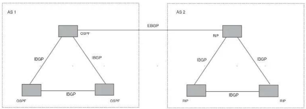
flowchart
graph TD
subgraph AS 1
OSPF["OSPF"] -->|IBGP| OSPF1["OSPF"]
OSPF1 -->|IBGP| OSPF2["OSPF"]
OSPF2 -->|IBGP| OSPF3["OSPF"]
end
subgraph AS 2
RIP1["RIP"] -->|IBGP| RIP2["RIP"]
RIP2 -->|IBGP| RIP3["RIP"]
RIP3 -->|IBGP| RIP4["RIP"]
end
OSPF1 <-->|EBGP| RIP1
OSPF2 <-->|EBGP| RIP2
OSPF3 <-->|EBGP| RIP3
style AS 1 fill:#f9f,stroke:#333
style AS 2 fill:#f9f,stroke:#333
Relationship between the BGP4 route table and the IP route table
The device's BGP4 route table can have multiple routes or paths to the same destination, which are learned from different BGP4 neighbors. A BGP4 neighbor is another router that also is running BGP4. BGP4 neighbors communicate using Transmission Control Protocol (TCP) port 179 for BGP communication. When you configure the device for BGP4, one of the configuration tasks you perform is to identify the device's BGP4 neighbors.
Although a router's BGP4 route table can have multiple routes to the same destination, the BGP4 protocol evaluates the routes and chooses only one of the routes to send to the IP route table. The route that BGP chooses and sends to the IP route table is the preferred route. This route is what the device advertises to other BGP neighbors. If the preferred route goes down, BGP4 updates the route information in the IP route table with a new BGP4 preferred route.
NOTE
If IP load sharing is enabled and you enable multiple equal-cost paths for BGP4, BGP4 can select more than one equal-cost path to a destination.
A BGP4 route consists of the following information:
- Network number (prefix) – A value comprised of the network mask bits and an IP address (
/ ); for example, 192.215.129.0/18 indicates a network mask of 18 bits applied to the IP address 192.215.129.0. When a BGP4 device advertises a route to one of its neighbors, the route is expressed in this format. - AS-path – A list of the other ASs through which a route passes. BGP4 routers can use the AS-path to detect and eliminate routing loops. For example, if a route received by a BGP4 router contains the AS that the router is in, the router does not add the route to its own BGP4 table. (The BGP4 RFCs refer to the AS-path as "AS_PATH".)
- Additional path attributes – A list of additional parameters that describe the route. The route MED and next hop are examples of these additional path attributes.
NOTE
The device re-advertises a learned best BGP4 route to the device's neighbors even when the route table manager does not select that route for installation in the IP route table. This can happen if a route from another protocol, for example, OSPF, is preferred. The best BGP4 route is the route that BGP selects based on comparison of the BGP4 route path's attributes.
After a device successfully negotiates a BGP4 session with a neighbor (a BGP4 peer), the device exchanges complete BGP4 route tables with the neighbor. After this initial exchange, the device and all other RFC 1771-compliant BGP4 routers send UPDATE messages to inform neighbors of new, changed, or no longer feasible routes. BGP4 routers do not send regular updates. However, if configured to do so, a BGP4 router does regularly send KEEPALIVE messages to its peers to maintain BGP4 sessions with them if the router does not have any route information to send in an UPDATE message. Refer to “BGP4 message types” on page 742 for information about BGP4 messages.
How BGP4 selects a path for a route
When multiple paths for the same route prefix are known to a BGP4 router, the router uses the following algorithm to weigh the paths and determine the optimal path for the route. The optimal path depends on various parameters, which can be modified.
- Is the next hop accessible though an Interior Gateway Protocol (IGP) route? If not, ignore the path.
NOTE
By default, the device does not use the default route to resolve BGP4 next hop. Also refer to "Enabling next-hop recursion" on page 783 and "Using the IP default route as a valid next hop for a BGP4 route" on page 782
-
Use the path with the largest weight.
-
If the weights are the same, prefer the path with the largest local preference.
-
Prefer the route that was originated locally (by this BGP4 device).
-
If the local preferences are the same, prefer the path with the shortest AS-path. An AS-SET counts as 1. A confederation path length, if present, is not counted as part of the path length.
NOTE
This step can be skipped if bgp-as-path-ignore is configured.
-
If the AS-path lengths are the same, prefer the path with the lowest origin type. From low to high, route origin types are valued as follows:
-
IGP is lowest
-
EGP is higher than IGP but lower than INCOMPLETE
• INCOMPLETE is highest -
If the paths have the same origin type, prefer the path with the lowest MED.
- The device compares the MEDs of two otherwise equivalent paths if and only if the routes were learned from the same neighboring AS. This behavior is called deterministic MED. Deterministic MED is always enabled and cannot be disabled.
In addition, you can enable the device to always compare the MEDs, regardless of the AS information in the paths. To enable this comparison, enter the always-compare-med command at the BGP4 configuration level of the CLI. This option is disabled by default.
NOTE
By default, value 0 (most favorable) is used in MED comparison when the MED attribute is not present. The default MED comparison results in the device favoring the route paths that are missing their MEDs. You can use the med-missing-as-worst command to make the device regard a BGP route with a missing MED attribute as the least favorable path, when comparing the MEDs of the route paths.
NOTE
MED comparison is not performed for internal routes originated within the local AS or confederation unless the compare-med-empty-aspath command is configured.
-
Prefer paths in the following order:
-
Routes received through EBGP from a BGP4 neighbor outside of the confederation
- Routes received through EBGP from a BGP4 router within the confederation
-
Routes received through IBGP
-
If all the comparisons above are equal, prefer the route with the lowest IGP metric to the BGP4 next hop. This is the closest internal path inside the AS to reach the destination.
-
If the internal paths also are the same and BGP4 load sharing is enabled, load share among the paths otherwise go to Step 11.
NOTE
The BigIron RX supports BGP4 load sharing among multiple equal-cost paths. BGP4 load sharing enables the device to balance the traffic across the multiple paths instead of choosing just one path based on router ID. For EBGP routes, load sharing applies only when the paths are from neighbors within the same remote AS. EBGP paths from neighbors in different ASs are not compared, unless multipath multi-as is enabled.
- Prefer the path that comes from the BGP4 router with the lowest router ID, if compare-router ID is enabled. If a path contains originator ID attributes, then originator ID is substituted for the ROUTER ID in the decision process.
- Prefer the path with the minimum cluster list length.
- If the route is a BGP VRF instance, prefer the route with the smallest RD value.
BGP4 message types
BGP4 routers communicate with their neighbors (other BGP4 routers) using the following types of messages:
- OPEN
- UPDATE
- KEEPALIVE
- NOTIFICATION
- ROUTE REFRESH
OPEN message
After a BGP4 router establishes a TCP connection with a neighboring BGP4 router, the routers exchange OPEN messages. An OPEN message indicates the following:
- BGP version – Indicates the version of the protocol that is in use on the router. BGP version 4 supports Classless Interdomain Routing (CIDR) and is the version most widely used in the Internet. Version 4 also is the only version supported on the BigIron RX.
- AS number – A two-byte number that identifies the AS to which the BGP4 router belongs.
- Hold Time – The number of seconds a BGP4 router will wait for an UPDATE or KEEPALIVE message (described below) from a BGP4 neighbor before assuming that the neighbor is dead. BGP4 routers exchange UPDATE and KEEPALIVE messages to update route information and maintain communication. If BGP4 neighbors are using different Hold Times, the lowest Hold Time is used by the neighbors. If the Hold Time expires, the BGP4 router closes its TCP connection to the neighbor and clears any information it has learned from the neighbor and cached.
You can configure the Hold Time to be 0, in which case a BGP4 router will consider its
neighbors to always be up. For directly-attached neighbors, you can configure the BigIron RX to immediately close the TCP connection to the neighbor and clear entries learned from an EBGP neighbor if the interface to that neighbor goes down. This capability is provided by the fast external fallover feature, which is disabled by default.
- BGP Identifier – The router ID. The BGP Identifier (router ID) identifies the BGP4 router to other BGP4 routers. The BigIron RX use the same router ID for OSPF and BGP4. If you do not set a router ID, the software uses the IP address on the lowest numbered loopback interface configured on the router. If the device does not have a loopback interface, the default router ID is the lowest numbered IP address configured on the device. For more information or to change the router ID, refer to “Changing the router ID” on page 790.
- Parameter list – An optional list of additional parameters used in peer negotiation with BGP4 neighbors.
UPDATE message
After BGP4 neighbors establish a BGP4 connection over TCP and exchange their BGP4 routing tables, they do not send periodic routing updates. Instead, a BGP4 neighbor sends an update to its neighbor when it has a new route to advertise or routes have changed or become unfeasible. An UPDATE message can contain the following information:
- Network Layer Reachability Information (NLRI) – The mechanism by which BGP4 supports Classless Interdomain Routing (CIDR). An NLRI entry consists of an IP prefix that indicates a network being advertised by the UPDATE message. The prefix consists of an IP network number and the length of the network portion of the number. For example, an UPDATE message with the NLRI entry 192.215.129.0/18 indicates a route to IP network 192.215.129.0 with network mask 255.255.192.0. The binary equivalent of this mask is 18 consecutive one bits, thus “18” in the NLRI entry.
- Path attributes – Parameters that indicate route-specific information such as path information, route preference, next hop values, and aggregation information. BGP4 uses the path attributes to make filtering and routing decisions.
- Unreachable routes – A list of routes that have been in the sending router's BGP4 table but are no longer feasible. The UPDATE message lists unreachable routes in the same format as new routes.
/ .
KEEPALIVE message
BGP4 routers do not regularly exchange UPDATE messages to maintain the BGP4 sessions. For example, if a device configured to perform BGP4 routing has already sent the latest route information to its peers in UPDATE messages, the router does not send more UPDATE messages. Instead, BGP4 routers send KEEPALIVE messages to maintain the BGP4 sessions. KEEPALIVE messages are 19 bytes long and consist only of a message header; they contain no routing data.
BGP4 routers send KEEPALIVE messages at a regular interval, the Keep Alive Time. The default Keep Alive Time on device is 60 seconds.
A parameter related to the Keep Alive Time is the Hold Time. A BGP4 router's Hold Time determines how many seconds the router will wait for a KEEPALIVE or UPDATE message from a BGP4 neighbor before deciding that the neighbor is dead. The Hold Time is negotiated when BGP4 routers exchange OPEN messages; the lower Hold Time is then used by both neighbors. For example, if
BGP4 Router A sends a Hold Time of 5 seconds and BGP4 Router B sends a Hold Time of 4 seconds, both routers use 4 seconds as the Hold Time for their BGP4 session. The default Hold Time is 180 seconds. Generally, the Hold Time is configured to three times the value of the Keep Alive Time.
If the Hold Time is 0, a BGP4 router assumes that its neighbor is alive regardless of how many seconds pass between receipt of UPDATE or KEEPALIVE messages.
NOTIFICATION message
When you close the router's BGP4 session with a neighbor, or the router detects an error in a message received from the neighbor, or an error occurs on the router, the router sends a NOTIFICATION message to the neighbor. No further communication takes place between the BGP4 router that sent the NOTIFICATION and the neighbors that received the NOTIFICATION.
REFRESH message
BGP sends a REFRESH message to a neighbor to request the neighbor to resend route updates. This type of message can be useful if an inbound route filtering policy has been changed.
Brocade implementation of BGP4
BGP4 is described in RFC 1771 and the latest BGP drafts. The Brocade implementation fully complies with RFC 1771 and also supports the following:
• RFC 1745 (OSPF Interactions)
• RFC 1997 (BGP Communities Attributes)
• RFC 2385 (TCP MD5 Signature Option)
• RFC 2439 (Route Flap Dampening)
• RFC 2796 (Route Reflection)
• RFC 2842 and 3392 (Capability Advertisement)
• RFC 3065 (BGP4 Confederations)
• RFC 2858 (Multiprotocol Extensions)
• RFC 2918 (Route Refresh Capability)
• RFC 3392 (BGP Capability Advertisement)
Memory considerations
BGP4 handles a very large number of routes and therefore requires a lot of memory. For example, in a typical configuration with just a single BGP4 neighbor, a BGP4 router may need to be able to hold up to 150,000 routes. Many configurations, especially those involving more than one neighbor, can require the router to hold even more routes. The device provide dynamic memory allocation for BGP4 data. These devices automatically allocate memory when needed to support BGP4 neighbors, routes, and route attribute entries. Dynamic memory allocation is performed automatically by the software and does not require a reload.
As a guideline, BigIron RX switches with a 2 GB Management 4 module can accommodate 150 – 200 neighbors, with the assumption that the BigIron RX receives about one million routes total from all neighbors and sends about eight million routes total to neighbors. For each additional one million incoming routes, the capacity for outgoing routes decreases by around two million.
Configuring BGP4
Once you activate BGP, you can configure the BGP options. On a BigIron RX there are two configuration levels: global and address family.
At the global level, all BGP configurations apply to IPv4 and IPv6. You enter this layer using the router bgp command.
Under the global level, you specify an address family. Address families separate the IPv4 and IPv6 BGP configuration. You enter this level by entering the address-family command at the router bgp level. The command requires you to specify the IPv4 or IPv6 network protocol.
The address family command also requires you to select a sub-address family, which is the type of routes for the configuration. You specify multicast or unicast routes.
FIGURE 112 BGP configuration levels

flowchart
graph TD
A["router bgp"] --> B["Global commands for BGP and all address families"]
B --> C["address-family IPv6 unicast"]
B --> D["Commands for IPv6 BGP unicast routes"]
B --> E["address-family IPv4"]
E --> F["multicast Commands for IPv4 MBGP routes"]
E --> G["unicast Commands for IPv4 BGP unicast routes"]
Table 26.1 shows what commands are available at the various BGP configuration levels.
TABLE 120 IPv4 BGP commands at different configuration levels
| Command Global | (iPv4 and IPv6) | IPv4 address family unicast | IPv4 address family multicast | See |
| address-family x x x “Entering and exiting the address family | configuration level” on page 751 | |||
| address-filter | x | “Filtering specific IP addresses” on page 751 | ||
| aggregate-address x x “Aggregating routes advertised to BGP4 | neighbors” on page 759 | |||
| always-compare-med | x | “Configuring the device to always compare MEDs” on page 759 | ||
as-path-filter
X
TABLE 120 IPv4 BGP commands at different configuration levels (Continued)
| Command | Global (IPv4 and IPv6) | IPv4 address family unicast | IPv4 address family multicast | See |
| as-path-ignore x “Disabling or re-enabling comparison of the AS-path length” on page 760 | ||||
| bgp-redistribute-internal | x | “Redistributing IBGP routes” on page 760 | ||
| client-to-client-reflection “Disabling or re-enabling client-to-client route reflection” on page 761 | ||||
| cluster-id | x | “Configuring a route reflector” on page 761 | ||
| community-filter x | ||||
| compare-routerid x “Enabling or disabling comparison of the router IDs” on page 761 | ||||
| confederation | x | “Configuring confederations” on page 762 | ||
| dampening | x | x | “Configuring route flap dampening” on page 765 | |
| default-information-origi nate | x | x | “Originating the default route” on page 765 | |
| default-local-preference | x | “Changing the default local preference” on page 766 | ||
| default-metric | x | x | “Changing the default metric used for redistribution” on page 766 | |
| distance | x | “Changing administrative distances” on page 767 | ||
| enforce-first-as | x | “Requiring the first AS to be the neighbor's AS” on page 768 | ||
| exit-address-family | x | x | x | “Entering and exiting the address family configuration level” on page 751 |
| fast-external-fallover | x | “Enabling fast external fallover” on page 768 | ||
| local-as | x | “Setting the local AS number” on page 769 | ||
| maximum-paths x “Changing the maximum number of shared BGP4 paths” on page 769 | ||||
| med-missing-as-worst | x | “Treating missing MEDs as the worst MEDs” on page 770 | ||
| multipath | x | “Customizing BGP4 load sharing” on page 770 | ||
| neighbor | x | x | x | “Configuring BGP4 neighbors” on page 771“Configuring a BGP4 peer group” on page 778 |
| network | x | x | “Specifying a list of networks to advertise” on page 781 | |
| next-hop-enable-default | x | “Using the IP default route as a valid next hop for a BGP4 route” on page 782 | ||
| next-hop-recursion | x | “Enabling next-hop recursion” on page 783 | ||
| Command Global | (iPv4 and IPv6) | IPv4 address family unicast | IPv4 address family multicast | See |
| redistribute | x | x | “Modifying redistribution parameters” on page 786 | |
| show x x x “Displaying BGP4 information” on page 824 | ||||
| table-map | x | x | “Using a table map to set the tag value” on page 789 | |
| timers x “Changing the keep alive time and hold time” | on page 789 | |||
| update-time x x “Changing the BGP4 next-hop update timer” | on page 790 | |||
TABLE 121 IPv4 and IPv6 BGP Commands at Different Configuration Levels
| Command Global | (iPv4 and IPv6) | IPv4 Address Family Unicast | IPv4 Address Family Multicast | IPv6 Address Family Unicast | See |
| address-family | x | x | x | x | “Entering and exiting the address family configuration level” on page 751 |
| address-filter | x | “Filtering specific IP addresses” on page 751 | |||
| aggregate-address | x | x | x | “Aggregating routes advertised to BGP4 neighbors” on page 759 | |
| always-compare-med | x | “Configuring the device to always compare MEDs” on page 759 | |||
| as-path-filter | x | ||||
| as-path-ignore | x | “Disabling or re-enabling comparison of the AS-path length” on page 760 | |||
| bgp-redistribute-internal | x | x | “Redistributing IBGP routes” on page 760 | ||
| client-to-client-reflection | x “Disabling or re-enabling client-to-client route reflection” on page 761 | ||||
| cluster-id | x | “Configuring a route reflector” on page 761 | |||
| community-filter | x | ||||
| compare-routerid | x | “Enabling or disabling comparison of the router IDs” on page 761 | |||
| confederation | x | “Configuring confederations” on page 762 | |||
| dampening | x | x | x | “Configuring route flap dampening” on page 765 | |
| Command | Global (IPv4 and IPv6) | IPv4 Address Family Unicast | IPv4 Address Family Multicast | IPv6 Address Family Unicast | See |
| default-information-originate | x | x | x | "Originating the default route" on page 765 | |
| default-local-preference | x "Changing the default local preference" on | page 766 | |||
| default-metric x x x "Changing the default metric used for | redistribution" on page 766 | ||||
| distance x "Changing administrative distances" on | page 767 | ||||
| enforce-first-as x "Requiring the first AS to be the neighbor's | AS" on page 768 | ||||
| exit-address-family x x x x "Entering and exiting the address family | configuration level" on page 751 | ||||
| fast-external-fallover | x | "Enabling fast external fallover" on page 768 | |||
| local-as | x | "Setting the local AS number" on page 769 | |||
| maximum-paths | x | x | "Changing the maximum number of shared BGP4 paths" on page 769 | ||
| med-missing-as-worst | x | "Treating missing MEDs as the worst MEDs" on page 770 | |||
| multipath | x | x | "Customizing BGP4 load sharing" on page 770 | ||
| neighbor | x | x | x | x | "Configuring BGP4 neighbors" on page 771 "Configuring a BGP4 peer group" on page 778 |
| network | x | x | x | "Specifying a list of networks to advertise" on page 781 | |
| next-hop-enable-default | x | x | "Using the IP default route as a valid next hop for a BGP4 route" on page 782 | ||
| next-hop-recursion | x | "Enabling next-hop recursion" on page 783 | |||
| redistribute | x | x | x | "Modifying redistribution parameters" on page 786 | |
| show | x | x | x | x | "Displaying BGP4 information" on page 824 |
| table-map | x | x | x | "Using a table map to set the tag value" on page 789 | |
| timers | x "Changing the keep alive time and hold | time" on page 789 | |||
| update-time | x | x | "Changing the BGP4 next-hop update timer" on page 790 | ||
When parameter changes take effect
Some parameter changes take effect immediately while others do not take full effect until the router's sessions with its neighbors are reset.
Immediately
The following parameter changes take effect immediately:
- Enable or disable BGP.
- Set or change the local AS.
- Add neighbors.
- Change the update timer for route changes.
- Disable or enable fast external fallover.
- Specify individual networks that can be advertised.
- Change the default local preference, default information originate setting, or administrative distance.
- Enable or disable use of a default route to resolve a BGP4 next-hop route.
- Enable or disable MED (metric) comparison.
- Require the first AS in an Update from an EBGP neighbor to be the neighbor's AS.
- Change MED comparison parameters.
- Disable comparison of the AS-Path length.
- Enable comparison of the router ID.
- Enable next-hop recursion.
- Change the default metric.
- Disable or re-enable route reflection.
- Configure confederation parameters.
- Disable or re-enable load sharing.
- Change the maximum number of load-sharing paths.
- Change other load-sharing parameters.
- Define route flap dampening parameters.
- Add, change, or negate redistribution parameters (except changing the default MED; see below).
- Add, change, or negate route maps (when used by the network command or a redistribution command).
- Aggregate routes.
After resetting neighbor sessions
The following parameter changes take effect only after the router's BGP4 sessions are cleared, or reset using the "soft" clear option (Refer to "Closing or resetting a neighbor session" on page 821):
- Change the Hold Time or Keep Alive Time.
- Add, change, or negate filter tables that affect inbound and outbound route policies.
After disabling and re-enabling redistribution
The following parameter change takes effect only after you disable and then re-enable redistribution:
- Change the default MED (metric).
Activating and disabling BGP4
BGP4 is disabled by default. To enable BGP4 and place your BigIron RX into service as a BGP4 router, you must perform the following required steps.
-
Enable the BGP4 protocol.
-
Set the local AS number.
NOTE
BGP4 is not functional until you specify the local AS number.
- Add each BGP4 neighbor (peer BGP4 router) and identify the AS the neighbor is in.
- Save the BGP4 configuration information to the system configuration file.
For example, enter commands such as the following.
BigIron RX> enable
BigIron RX# configure terminal
BigIron RX(config)# router bgp
BGP4: Please configure 'local-as' parameter in order to enable BGP4.
BigIron RX(config-bgp)# local-as 10
BigIron RX(config-bgp)# write memory
The router bgp command enables the BGP4 protocol.
(For information on the local AS number, refer to "Setting the local AS number" on page 769.)
NOTE
By default, the Brocade router ID is the IP address configured on the lowest numbered loopback interface. If the device does not have a loopback interface, the default router ID is the lowest numbered IP interface address configured on the device. For more information, refer to “Changing the router ID” on page 790. If you change the router ID, all current BGP4 sessions are cleared.
NOTE
When BGP4 is enabled on a BigIron RX, you do not need to reset the system. The protocol is activated as soon as you enable it. Moreover, the router begins a BGP4 session with a BGP4 neighbor as soon as you add the neighbor.
Note regarding disabling BGP4
If you disable BGP4, the BigIron RX removes all the running configuration information for the disabled protocol from the running configuration. To restore the BGP4 configuration, you must reload the software to load the configuration from the startup configuration. Moreover, when you save the configuration to the startup configuration file after disabling the protocol, all the configuration information for the disabled protocol is removed from the startup configuration file.
The CLI displays a warning message such as the following.
BigIron RX(config)# no router bgp
router bgp mode now disabled. All bgp config data will be lost when writing to flash!
The Web management interface does not display a warning message.
If you are testing a BGP4 configuration and are likely to disable and re-enable the protocol, you might want to make a backup copy of the startup configuration file containing the protocol's configuration information. This way, if you remove the configuration information by saving the configuration after disabling the protocol, you can restore the configuration by copying the backup copy of the startup configuration file onto the flash memory.
To disable BGP4 without losing the BGP4 configuration information, remove the local AS (for example, by entering the no local-as
Entering and exiting the address family configuration level
The BGP address family has a unicast or multicast sub-level.
To enter the IPv4 BGP unicast address family configuration level, enter the following command.
BigIron RX(config-bgp)# address-family ipv4 unicast BigIron RX(config-bgp)#
NOTE
The CLI prompt for the global BGP level and the BGP address-family IPv4 unicast level are the same.
To enter the IPv4 BGP multicast address family configuration level, enter the following command.
BigIron RX(config-bgp)# address-family ipv4 multicast BigIron RX(config-bgp-ipv4m)#
Syntax: [no] address-family ipv4 unicast | ipv4 multicast
The default is the ipv4 unicast address family level.
To exit an address family configuration level, enter the following command.
BigIron RX(config-bgp-ipv6u)# exit-address-family BigIron RX(config-bgp)#
Syntax: exit-address-family
Filtering specific IP addresses
You can configure the router to explicitly permit or deny specific IP addresses received in updates from BGP4 neighbors by defining IP address filters. The router permits all IP addresses by default. You can define up to 100 IP address filters for BGP4.
- If you want permit to remain the default behavior, define individual filters to deny specific IP addresses.
- If you want to change the default behavior to deny, define individual filters to permit specific IP addresses.
NOTE
Once you define a filter, the default action for addresses that do not match a filter is "deny". To change the default action to "permit", configure the last filter as "permit any any".
Address filters can be referred to by a BGP neighbor's distribute list number as well as by match statements in a route map.
NOTE
If the filter is referred to by a route map's match statement, the filter is applied in the order in which the filter is listed in the match statement.
NOTE
You also can filter on IP addresses by using IP ACLs. See “Software-Based IP Access Control Lists (ACLs)”.
To define an IP address filter to deny routes to 209.157.0.0, enter the following command.
BigIron RX(config-bgp)# address-filter 1 deny 209.157.0.0 255.255.0.0
Syntax: [no] address-filter
The
The permit | deny parameter indicates the action the device takes if the filter match is true.
- If you specify permit, the device permits the route into the BGP4 table if the filter match is true.
- If you specify deny, the device denies the route from entering the BGP4 table if the filter match is true.
NOTE
Once you define a filter, the default action for addresses that do not match a filter is "deny". To change the default action to "permit", configure the last filter as "permit any any".
The
The
If you prefer to specify the wildcard (mask value) in Classless Interdomain Routing (CIDR) format, you can enter a forward slash after the IP address, then enter the number of significant bits in the mask. For example, you can enter the CIDR equivalent of "209.157.22.26 0.0.0.255" as "209.157.22.26/24". The CLI automatically converts the CIDR number into the appropriate mask (where zeros instead of ones are the significant bits) and changes the non-significant portion of the IP address into zeros. For example, if you specify 209.157.22.26/24 or 209.157.22.26 0.0.0.255, then save the changes to the startup configuration file, the value appears as 209.157.22.0/24 (if you have enabled display of subnet lengths) or 209.157.22.0 0.0.0.255 in the startup configuration file.
If you enable the software to display IP subnet masks in CIDR format, the mask is saved in the file in "/
The
Defining an AS-path filter
To define an AS-path filter, enter the command such as the following.
BigIron RX(config-bgp)# as-path-filter 4 permit 2500
The command defines AS-path filter 4 to permit AS 2500.
Syntax: [no] as-path-filter
The
NOTE
If the filter is referred to by a route map's match statement, the filter is applied in the order in which the filter is listed in the match statement.
The permit | deny parameter indicates the action the router takes if the filter match is true.
- If you specify permit, the router permits the route into the BGP4 table if the filter match is true.
- If you specify deny, the router denies the route from entering the BGP4 table if the filter match is true.
The
Defining a community filter
To define filter 3 to permit routes that have the NO_ADVERTISE community, enter the following command.
BigIron RX(config-bgp)# community-filter 3 permit no-advertise
Syntax: [no] community-filter
The
NOTE
If the filter is referred to by a route map's match statement, the filter is applied in the order in which the filter is listed in the match statement.
The permit | deny parameter indicates the action the router takes if the filter match is true.
- If you specify permit, the router permits the route into the BGP4 table if the filter match is true.
- If you specify deny, the router denies the route from entering the BGP4 table if the filter match is true.
The
If you want to filter for the well-known communities "LOCAL_AS", "NO_EXPORT" or "NO_ADVERTISE", use the corresponding keyword (described below).
The internet keyword checks for routes that do not have the community attribute. Routes without a specific community are considered by default to be members of the largest community, the Internet.
The local-as keyword checks for routes with the well-known community “LOCAL_AS”. This community applies only to confederations. The device advertises the route only within the sub-AS. For information about confederations, refer to “Configuring confederations” on page 762.
The no-advertise keyword filters for routes with the well-known community "NO_ADVERTISE". A route in this community should not be advertised to any BGP4 neighbors.
The no-export keyword filters for routes with the well-known community "NO_EXPORT". A route in this community should not be advertised to any BGP4 neighbors outside the local AS. If the router is a member of a confederation, the device advertises the route only within the confederation. For information about confederations, refer to "Configuring confederations" on page 762.
Configuring a switch to allow routes with its own AS number
BGP rejects routes that contain its own AS number within its AS_PATH attribute to prevent routing loops. In an VPN hub and spoke topology this can stop legitimate routes from being accepted. In this release, the allowas-in command eliminates this problem by allowing you to set a parameter that disables the AS_PATH check function for routes learned from a specified location.
To configure a switch to disable the AS_PATH check function for routes sent to it by its BGP neighbor for a maximum limit of 3 occurrences of the route, enter the following command at the BGP configuration level.
BigIron RX(config-bgp-ipv4u)# neighbor 33.33.36.2 allowas-in 3
Syntax: neighbor
The
The asn_limit value prevents loops by limiting the number of occurrences that the AS number will be accepted in routes that are received from the specified switch. The maximum limit is 10.
BGP Null0 routing
BGP can use the null0 route to resolve its next hop. Thus, null0 route in the routing table (for example, static route) is considered as a valid route by BGP. If the next hop for BGP resolves into a null0 route, the BGP route is also installed as a null0 route in the routing table.
The null0 routing feature allows network administrators to block certain network prefixes, by using null0 routes and route-maps. The combined use of null0 routes and route maps blocks traffic from a particular network prefix, telling a remote router to drop all traffic for this network prefix by redistributing a null0 route into BGP.
Figure 113 shows a topology for a null0 routing application example.
FIGURE 113 Sample Null0 routing application

flowchart
graph TD
Internet["Internet"] --> R1["R1"]
Internet --> R2["R2"]
R1 --> AS100["AS 100"]
R2 --> AS100
R3["R3"] --> AS100
R4["R4"] --> AS100
AS100 --> R6R7R5["R6 R7R5"]
AS100 --> R6R7R5
AS100 --> R6R7R5
R6R7R5 --> R4
R6R7R5 --> R4
R6R7R5 --> R4
R6R7R5 --> R4
R6R7R5 --> R4
R6R7R5 --> R4
R6R7R5 --> R4
R6R7R5 --> R4
R6R7R5 --> R4
R6R7R5 --> R4
The following steps configure a null0 routing application for stopping denial of service attacks from remote hosts on the internet.
Configuration steps
- Select one router, Router 6, to distribute null0 routes throughout the BGP network.
- Configure a route-map to match a particular tag (50) and set the next-hop address to an unused network address (199.199.1.1).
- Set the local-preference to a value higher than any possible internal or external local-preference (50).
-
Complete the route map by setting origin to IGP.
-
On Router 6, redistribute the static routes into BGP, using route-map
(redistribute static route-map block user). - On Router 1, the router facing the internet, configure a null0 route matching the next-hop address in the route-map (ip route 199.199.1.1/32 null0).
- Repeat step 3 for all routers interfacing with the internet (edge corporate routers). In this case, Router 2 has the same null0 route as Router 1.
- On Router 6, configure the network prefixes associated with the traffic you want to drop. The static route IP address references a destination address. You are required to point the static route to the egress port, for example, Ethernet 3/7, and specify the tag 50, matching the route-map configuration.
Configuration examples
Router 6
The following configuration defines specific prefixes to filter.
BigIron RX(config)#ip route 110.0.0.40/29 ethernet 3/7 tag 50
BigIron RX(config)#ip route 115.0.0.192/27 ethernet 3/7 tag 50
BigIron RX(config)#ip route 120.014.0/23 ethernet 3/7 tag 50
The following configuration redistributes routes into BGP.
BigIron RX(config)#router bgp
BigIron RX(config-bgp-router)#local-as 100
BigIron RX(config-bgp-router)#neighbor <router1_int_ip address> remote-as 100
BigIron RX(config-bgp-router)#neighbor <router2_int_ip address> remote-as 100
BigIron RX(config-bgp-router)#neighbor <router3_int_ip address> remote-as 100
BigIron RX(config-bgp-router)#neighbor <router4_int_ip address> remote-as 100
BigIron RX(config-bgp-router)#neighbor <router5_int_ip address> remote-as 100
BigIron RX(config-bgp-router)#neighbor <router7_int_ip address> remote-as 100
BigIron RX(config-bgp-router)#redistribute static route-map blockuser
BigIron RX(config-bgp-router)#exit
The following configuration defines the specific next hop address and sets the local preference to preferred.
BigIron RX(config)#route-map blockuser permit 10
BigIron RX(config-routemap blockuser)#match tag 50
BigIron RX(config-routemap blockuser)#set ip next-hop 199.199.1.1
BigIron RX(config-routemap blockuser)#set local-preference 1000000
BigIron RX(config-routemap blockuser)#set origin igp
BigIron RX(config-routemap blockuser)#exit
Router 1
The following configuration defines the null0 route to the specific next hop address. The next hop address 199.199.1.1 points to 128.178.1.101, which gets blocked.
BigIron RX(config)# ip route 199.199.1.1/32 null0
BigIron RX(config)#router bgp
local-as 100
BigIron RX(config-bgp-router)#neighbor <router2_int_ip address> remote-as 100
BigIron RX(config-bgp-router)#neighbor <router3_int_ip address> remote-as 100
BigIron RX(config-bgp-router)#neighbor <router4_int_ip address> remote-as 100
BigIron RX(config-bgp-router)#neighbor <router5_int_ip address> remote-as 100
BigIron RX(config-bgp-router)#neighbor <router6_int_ip address> remote-as 100
BigIron RX(config-bgp-router)#neighbor <router7_int_ip address> remote-as 100
Router 2
The following configuration defines a null0 route to the specific next hop address. The next hop address 199.199.1.1 points to 128.178.1.101, which gets blocked.
BigIron RX(config)#ip route 199.199.1.1/32 null0
BigIron RX(config)#router bgp
BigIron RX(config-bgp-router)#local-as 100
BigIron RX(config-bgp-router)#neighbor <router1_int_ip address> remote-as 100
BigIron RX(config-bgp-router)#neighbor <router3_int_ip address> remote-as 100
BigIron RX(config-bgp-router)#neighbor <router4_int_ip address> remote-as 100
BigIron RX(config-bgp-router)#neighbor <router5_int_ip address> remote-as 100
BigIron RX(config-bgp-router)#neighbor <router6_int_ip address> remote-as 100
BigIron RX(config-bgp-router)#neighbor <router7_int_ip address> remote-as 100
After configuring the null0 application, you can display the configuration using the show ip route static, show ip bgp route, and show ip route commands.
For example, when you issue the show ip route static command on Router 6, you see the following output.
BigIron RX# show ip route static
Type Codes - B:BGP D:Connected S:Static R:RIP O:OSPF; Cost - Dist/Metric
Destination Gateway Port Cost Type
1 110.0.0.40/29 DIRECT eth 3/7 1/1 S
2 115.0.0.192/27 DIRECT eth 3/7 1/1 S
3 120.0.14.0/23 DIRECT eth 3/7 1/1 S
BigIron RX#
Entering a show ip route static on Router 1 and Router 2 displays the following.
BigIron RX# show ip route static
Type Codes - B:BGP D:Connected S:Static R:RIP O:OSPF; Cost - Dist/Metric
Destination Gateway Port Cost Type
1 192.168.0.1/32 DIRECT drop 1/1 S
BigIron RX#
Entering a show BGP route on Router 6 displays its routing table.
| Router-6# show ip bgp route | ||||||
| Total number of BGP Routes: 126 | ||||||
| Status A:AGGREGATE B:BEST b:NOT-INSTALLED-BEST C:CONFED_EBGP D:DAMPED E:EBGP | ||||||
| H: HISTORY I: IBGP L: LOCAL M: MULTIPATH S: SUPPRESSED s: STALE | ||||||
| Prefix | Next Hop | Metric | LocPrf | Weight | Status | |
| 1 | 30.0.1.0/24AS_PATH: | 40.0.1.3 | 0 | 100 | 0 | BI |
| . | .. | . | . | . | ||
| . | ||||||
| 9 | 110.0.0.16/30AS_PATH: 85 | 90.0.1.3 | 100 | 0 | I | |
| 10 | 110.0.0.40/29AS_PATH: | 192.168.0.1 | 1 | 1000000 32768 | BL | |
| 11 | 110.0.0.80/28 | 90.0.1.3 | 100 | 0 | I | |
| . | .. | . | . | . | ||
| . | .. | . | . | . | ||
| . | ||||||
| 36 | 115.0.0.96/28AS_PATH: 50 | 30.0.1.3 | 100 | 0 | I | |
| 37 | 115.0.0.192/27AS_PATH: | 192.168.0.1 | 1 | 10000000 32768 | BL | |
| . | .. | . | . | . | ||
| . | ||||||
| 64 | 120.0.7.0/24AS_PATH: 10 | 70.0.1.3 | 100 | 0 | I | |
| 65 | 120.0.14.0/23AS_PATH: .. | 192.168.0.1 | 1 | 1000000 32768 | BL | |
| . | . | . | ||||
Issuing a show ip route on Router 1 and Router 2 shows "drop" under the Port column for the network prefixes you configured with null0 routing.
| BigIron RX# show ip route | |||||
| Total number of IP routes: 133 | |||||
| Type Codes - B:BGP D:Connected S:Static R:RIP O:OSPF; Cost - Dist/Metric | |||||
| Destination | Gateway | Port | Cost | Type | |
| 1 | 9.0.1.24/32 | DIRECT | loopback 1 | 0/0 | D |
| 2 | 30.0.1.0/24 | DIRECT | eth 2/7 | 0/0 | D |
| 3 | 40.0.1.0/24 | DIRECT | eth 2/1 | 0/0 | D |
| . | |||||
| 13 | 110.0.0.6/31 | 90.0.1.3 | eth 2/2 | 20/1 | B |
| 14 | 110.0.0.16/30 | 90.0.1.3 | eth 2/2 | 20/1 | B |
| 15 | 110.0.0.40/29 | DIRECT | drop | 200/0 | B |
| . | .. | . | . | . | . |
| 42 | 115.0.0.192/27 | DIRECT | drop | 200/0 | B |
| 43 | 115.0.1.128/26 | 30.0.1.3 | eth 2/7 | 20/1 | B |
| . | .. | . | . | . | . |
| 69 | 120.0.7.0/24 | 70.0.1.3 | eth 2/10 | 20/1 | B |
| 70 | 120.0.14.0/23 | DIRECT | drop | 200/0 | B |
| . | .. | . | . | . | . |
| . | .. | . | . | . | . |
| 131 | 130.144.0.0/12 | 80.0.1.3 | eth 3/4 | 20/1 | B |
| 132 | 192.168.0.1/32 | DIRECT | drop | 1/1 | S |
| BigIron RX# | |||||
Aggregating routes advertised to BGP4 neighbors
By default, the BigIron RX advertises individual routes for all the networks. The aggregation feature allows you to configure the device to aggregate routes in a range of networks into a single network prefix. For example, without aggregation, the device will individually advertise routes for networks 207.95.1.0/24, 207.95.2.0/24, and 207.95.3.0/24. You can configure the device to instead send a single, aggregate route for the networks. The aggregate route can be advertised as 207.95.0.0/16.
To aggregate routes for 209.157.22.0/24, 209.157.23.0/24, and 209.157.24.0/24, enter the following command.
BigIron RX(config-bgp)# aggregate-address 209.157.0.0 255.255.0.0
Syntax: aggregate-address
The
The as-set parameter causes the router to aggregate AS-path information for all the routes in the aggregate address into a single AS-path.
The summary-only parameter prevents the router from advertising more specific routes contained within the aggregate route.
The suppress-map
The advertise-map
The attribute-map
NOTE
For the suppress-map, advertise-map, and attribute-map parameters, the route map must already be defined. Refer to ““Defining route maps” on page 801 for information on defining a route map.
Configuring the device to always compare MEDs
A Multi-Exit Discriminator (MED) is a value that the BGP4 algorithm uses when comparing multiple paths received from different BGP4 neighbors in the same AS for the same route. In BGP4, a route's MED is equivalent to its “metric”.
BGP4 compares the MEDs of two otherwise equivalent paths if and only if the routes were learned from the same neighboring AS. This behavior is called deterministic MED. Deterministic MED is always enabled and cannot be disabled.
In addition, you can enable the device to always compare the MEDs, regardless of the AS information in the paths. To enable this comparison, enter the always-compare-med command at the BGP4 configuration level of the CLI. This option is disabled by default.
You can enable the device to always compare the MEDs, regardless of the AS information in the paths. For example, if the router receives UPDATES for the same route from neighbors in three ASs, the router would compare the MEDs of all the paths together, rather than comparing the MEDs for the paths in each AS individually.
NOTE
By default, value 0 (most favorable) is used in MED comparison when the MED attribute is not present. The default MED comparison results in the device favoring the route paths that are missing their MEDs. You can use the med-missing-as-worst command to make the device regard a BGP route with a missing MED attribute as the least favorable route, when comparing the MEDs of the routes.
NOTE
MED comparison is not performed for internal routes originated within the local AS or confederation unless the compare-med-empty-aspath command is configured.
NOTE
The AS-path is empty when routes are redistributed from other protocols (e.g. redistribute static, redistribute connected, or redistribute OSPF).
To configure the router to always compare MEDs, enter the following command.
BigIron RX(config-bgp)# always-compare-med
Syntax: [no] always-compare-med
The following BGP command directs BGP to take the MED value into consideration even if the route has an empty as-path path attribute.
BigIron RX(config) router bgp
BigIron RX(config-bgp-router)# compare-med-empty-aspath
Syntax: [no] compare-med-empty-aspath
Disabling or re-enabling comparison of the AS-path length
AS-Path comparison is Step 5 in the algorithm BGP4 uses to select the next path for a route. Comparison of the AS-Path length is enabled by default. To disable it, enter the following command at the BGP configuration level of the CLI.
BigIron RX(config-bgp)# as-path-ignore
This command disables comparison of the AS-Path lengths of otherwise equal paths. When you disable AS-Path length comparison, the BGP4 algorithm shown in "How BGP4 Selects a Path for a Route" on page 26-3 skips from Step 4 to Step 6.
Syntax: [no] as-path-ignore
Redistributing IBGP routes
By default, the device does not redistribute IBGP routes from BGP4 into RIP, OSPF, or ISIS. This behavior helps eliminate routing loops. However, if your network can benefit from redistributing the IBGP routes from BGP4 into OSPF, ISIS or RIP, you can enable the device to redistribute the routes.
To enable the device to redistribute BGP4 routes into OSPF, RIP, or ISIS, enter the following command.
BigIron RX(config-bgp)# bgp-redistribute-internal
Syntax: [no] bgp-redistribute-internal
To disable redistribution of IBGP routes into RIP, ISIS, and OSPF, enter the following command.
BigIron RX(config-bgp)# no bgp-redistribute-internal
Disabling or re-enabling client-to-client route reflection
By default, the clients of a route reflector are not required to be fully meshed; the routes from a client are reflected to other clients. However, if the clients are fully meshed, route reflection is not required between clients.
If you need to disable route reflection between clients, enter the following command. When the feature is disabled, route reflection does not occur between clients but reflection does still occur between clients and non-clients.
BigIron RX(config-bgp)# no client-to-client-reflection
Enter the following command to re-enable the feature.
BigIron RX(config-bgp)# client-to-client-reflection
Syntax: [no] client-to-client-reflection
Configuring a route reflector
You can configure one cluster ID on the router. All route-reflector clients for the router are members of the cluster.
To configure a device as route reflector 1, enter the following command.
BigIron RX(config-bgp)# cluster-id 1
Syntax: [no] cluster-id
The
The default is the router ID.
NOTE
If the cluster contains more than one route reflector, you need to configure the same cluster ID on all the route reflectors in the cluster. The cluster ID helps route reflectors avoid loops within the cluster.
Enabling or disabling comparison of the router IDs
Router ID comparison is step 11 in the algorithm BGP4 uses to select the next path for a route.
NOTE
Comparison of router IDs is applicable only when BGP4 load sharing is disabled.
When router ID comparison is enabled, the path comparison algorithm compares the router IDs of the neighbors that sent the otherwise equal paths.
- If BGP4 load sharing is disabled (maximum-paths 1), the device selects the path that came from the neighbor with the lower router ID.
- If BGP4 load sharing is enabled, the device load shares among the remaining paths. In this case, the router ID is not used to select a path.
NOTE
Router ID comparison is disabled by default.
To enable router ID comparison, enter the following command at the BGP configuration level of the CLI.
BigIron RX(config-bgp)# compare-routerid
Syntax: [no] compare-routerid
For more information, refer to "How BGP4 selects a path for a route" on page 740.
Configuring confederations
A confederation is a BGP4 Autonomous System (AS) that has been subdivided into multiple, smaller ASs. Subdividing an AS into smaller ASs simplifies administration and reduces BGP-related traffic, thus reducing the complexity of the Interior Border Gateway Protocol (IBGP) mesh among the BGP routers in the AS.
The Brocade implementation of this feature is based on RFC 3065.
Normally, all BGP routers within an AS must be fully meshed, so that each BGP router has BGP sessions to all the other BGP routers within the AS. This is feasible in smaller ASs but becomes unmanageable in ASs containing many BGP routers.
When you configure BGP routers into a confederation, all the routers within a sub-AS (a subdivision of the AS) use IBGP and must be fully meshed. However, routers use EBGP to communicate between different sub-ASs.
NOTE
Another method for reducing the complexity of an IBGP mesh is to use route reflection. However, if you want to run different Interior Gateway Protocols (IGPs) within an AS, configure a confederation. You can run a separate IGP within each sub-AS.
To configure a confederation, configure groups of BGP routers into sub-ASs. A sub-AS is simply an AS. The term “sub-AS” distinguishes ASs within a confederation from ASs that are not in a confederation. For the viewpoint of remote ASs, the confederation ID is the AS ID. Remote ASs do not know that the AS represents multiple sub-ASs with unique AS IDs.
NOTE
You can use any valid AS numbers for the sub-ASs. If your AS is connected to the Internet, Brocade recommends that you use numbers from within the private AS range (64512 - 65535). These are private ASs numbers and BGP4 routers do not propagate these AS numbers to the Internet.
Figure 114 shows an example of a BGP4 confederation.
FIGURE 114 Example BGP4 confederation

flowchart
graph TD
A["Confederation 10"] -->|IBGP| B["Sub-AS 64512"]
A -->|EBGP| C["Sub-AS 64513"]
C -->|IBGP| D["Router C"]
C --> E["Router D"]
F["AS 20"] --> G["This BGP4 router sees all traffic from Confederation 10 as traffic from AS 10. Routers outside the confederation do not know or care that the routers are subdivided into sub-ASs within a confederation."]
style A fill:#f9f,stroke:#333
style C fill:#f9f,stroke:#333
style F fill:#ccf,stroke:#333
In this example, four routers are configured into two sub-ASs, each containing two of the routers. The sub-ASs are members of confederation 10. Routers within a sub-AS must be fully meshed and communicate using IBGP. In this example, routers A and B use IBGP to communicate. Routers C and D also use IBGP. However, the sub-ASs communicate with one another using EBGP. For example, router A communicates with router C using EBGP. The routers in the confederation communicate with other ASs using EBGP.
Routers in other ASs are unaware that routers A – D are configured in a confederation. In fact, when routers in confederation 10 send traffic to routers in other ASs, the confederation ID is the same as the AS number for the routers in the confederation. Thus, routers in other ASs see traffic from AS 10 and are unaware that the routers in AS 10 are subdivided into sub-ASs within a confederation.
Configuring a BGP confederation
Perform the following configuration tasks on each BGP router within the confederation:
- Configure the local AS number. The local AS number indicates membership in a sub-AS. All BGP routers with the same local AS number are members of the same sub-AS. BGP routers use the local AS number when communicating with other BGP routers within the confederation.
- Configure the confederation ID. The confederation ID is the AS number by which BGP routers outside the confederation know the confederation. Thus, a BGP router outside the confederation is not aware and does not care that your BGP routers are in multiple sub-ASs. BGP routers use the confederation ID when communicating with routers outside the confederation. The confederation ID must be different from the sub-AS numbers.
- Configure the list of the sub-AS numbers that are members of the confederation. All the routers within the same sub-AS use IBGP to exchange router information. Routers in different sub-ASs within the confederation use EBGP to exchange router information.
The procedures show how to implement the example confederation shown in Figure 26.3.
To configure four devices to be a member of confederation 10, consisting of two sub-ASs (64512 and 64513), enter commands such as the following.
Commands for Router A
BigIron RXA(config)# router bgp
BigIron RXA(config-bgp)# local-as 64512
BigIron RXA(config-bgp)# confederation identifier 10
BigIron RXA(config-bgp)# confederation peers 64512 64513
BigIron RXA(config-bgp)# write memory
Syntax: local-as
The
Syntax: confederation identifier
The
Syntax: confederation peers
The
Commands for Router B
BigIron RXB(config)# router bgp
BigIron RXB(config-bgp)# local-as 64512
BigIron RXB(config-bgp)# confederation identifier 10
BigIron RXB(config-bgp)# confederation peers 64512 64513
BigIron RXB(config-bgp)# write memory
Commands for Router C
BigIron RXC(config)# router bgp
BigIron RXC(config-bgp)# local-as 64513
BigIron RXC(config-bgp)# confederation identifier 10
BigIron RXC(config-bgp)# confederation peers 64512 64513
BigIron RXC(config-bgp)# write memory
Commands for Router D
BigIron RXD(config)# router bgp
BigIron RXD(config-bgp)# local-as 64513
BigIron RXD(config-bgp)# confederation identifier 10
BigIron RXD(config-bgp)# confederation peers 64512 64513
BigIron RXD(config-bgp)# write memory
Configuring route flap dampening
Route Flap Dampening reduces the amount of change propagated by BGP due to routing state caused by unstable routes. Reducing change propagation will help reduce processing requirements.
To enable route flap dampening using the default values, enter the following command.
BigIron RX(config-bgp)# dampening
Syntax: dampening [
The
The
The
The
The following example shows how to change the dampening parameters.
BigIron RX(config-bgp)# dampening 20 200 2500 40
This command changes the half-life to 20 minutes, the reuse threshold to 200, the suppression threshold to 2500, and the maximum number of minutes a route can be dampened to 40.
NOTE
To change any of the parameters, you must specify all the parameters with the command. If you want to leave some parameters unchanged, enter their default values.
Originating the default route
By default, the device does not originate and advertise a default route using BGP4. A BGP4 default route is the IP address 0.0.0.0 and the route prefix 0 or network mask 0.0.0.0. For example, 0.0.0.0/0 is a default route.
NOTE
The device checks for the existence of an IGP route for 0.0.0.0/0 in the IP route table before creating a local BGP route for 0.0.0.0/0.
To enable the router to originate and advertise a default BGP4 route, enter the following command.
BigIron RX(config-bgp)# default-information-originate
Syntax: [no] default-information-originate
Changing the default local preference
When the router uses the BGP4 algorithm to select a route to send to the IP route table, one of the parameters the algorithm uses is the local preference. Local preference is an attribute that indicates a degree of preference for a route relative to other routes. BGP4 neighbors can send the local preference value as an attribute of a route in an UPDATE message.
Local preference applies only to routes within the local AS. BGP4 routers can exchange local preference information with neighbors who also are in the local AS, but BGP4 routers do not exchange local preference information with neighbors in remote ASs.
The default local preference is 100. For routes learned from EBGP neighbors, the default local preference is assigned to learned routes. For routes learned from IBGP neighbors, the local preference value is not changed for the route.
When the BGP4 algorithm compares routes on the basis of local preferences, the route with the higher local preference is chosen.
NOTE
To set the local preference for individual routes, use route maps. Refer to “Defining route maps” on page 801. Refer to “How BGP4 selects a path for a route” on page 740 for information about the BGP4 algorithm.
To change the default local preference to 200, enter the following command.
BigIron RX(config-bgp)# default-local-preference 200
Syntax: default-local-preference
The
Changing the default metric used for redistribution
The BigIron RX can redistribute directly connected routes, static IP routes, RIP routes, ISIS routes, and OSPF routes into BGP4. By default, BGP uses zero (0) for direct connected routes and the metric (MED) value of IGP routes in the IP route table. The MED is a global parameter that specifies the cost that will be applied to all routes, if assigned, when they are redistributed into BGP4. When routes are selected, lower metric values are preferred over higher metric values. The default, the BGP4 MED value is not assigned.
NOTE
RIP, ISIS, and OSPF also have default metric parameters. The parameters are set independently for each protocol and have different ranges.
To change the default metric to 40, enter the following command.
BigIron RX(config-bgp)# default-metric 40
Syntax: default-metric
The
Changing administrative distances
The BigIron RX can learn about networks from various protocols, including the EBGP portion of BGP4 and IGPs such as OSPF, ISIS, and RIP. Consequently, the routes to a network may differ depending on the protocol from which the routes were learned.
To select one route over another based on the source of the route information, the device can use the administrative distances assigned to the sources. The administrative distance is a protocol-independent metric that IP routers use to compare routes from different sources.
The device re-advertises a learned best BGP4 route to the device's neighbors even when the route table manager does not also select that route for installation in the IP route table. The best BGP4 route is the BGP4 path that BGP selects based on comparison of the paths' BGP4 route parameters. Refer to "How BGP4 selects a path for a route" on page 740.
When selecting a route from among different sources (BGP4, OSPF, RIP, ISIS, static routes, and so on), the software compares the routes on the basis of each route's administrative distance. If the administrative distance of the paths is lower than the administrative distance of paths from other sources (such as static IP routes, RIP, or OSPF), the BGP4 paths are installed in the IP route table.
Here are the default administrative distances on the BigIron RX:
- Directly connected - 0 (this value is not configurable)
- Static - 1 is the default and applies to all static routes, including default routes. This can be assigned a different value.
- EBGP - 20
- OSPF - 110
- ISIS - 115
- RIP - 120
- IBGP - 200
- Local BGP - 200
- Unknown – 255 (the router will not use this route)
Lower administrative distances are preferred over higher distances. For example, if the router receives routes for the same network from OSPF and from RIP, the router will prefer the OSPF route by default. The administrative distances are configured in different places in the software. The device re-advertises a learned best BGP4 route to neighbors by default, regardless of whether the route's administrative distance is lower than other routes from different route sources to the same destination.
- To change the EBGP, IBGP, and Local BGP default administrative distances, see the instructions in this section.
- To change the default administrative distance for OSPF, RIP, ISIS, refer to “Changing administrative distances” on page 767.
- To change the administrative distance for static routes, refer to “Configuring static routes” on page 198
To change the default administrative distances for EBGP, IBGP, and Local BGP, enter a command such as the following.
BigIron RX(config-bgp)# distance 200 200 200
Syntax: distance
The
The
The
Requiring the first AS to be the neighbor's AS
By default, the BigIron RX does not require the first AS listed in the AS_SEQUENCE field of an AS path Update from an EBGP neighbor to be the AS that the neighbor who sent the Update is in. You can enable the device for this requirement.
When you enable the device to require the AS that an EBGP neighbor is in to be the same as the first AS in the AS_SEQUENCE field of an Update from the neighbor, the device accepts the Update only if the ASs match. If the ASs do not match, the device sends a Notification message to the neighbor and closes the session. The requirement applies to all Updates received from EBGP neighbors.
To enable this feature, enter the following command at the BGP configuration level of the CLI.
BigIron RX(config-bgp)# enforce-first-as
Syntax: [no] enforce-first-as
Neighbor local-AS
The Neighbor Local Autonomous System (AS) allows a router that is a member of one AS to appear to also be a member of another AS. This feature is useful, for example, if Company A purchases Company B, but Company B does not want to modify its peering configurations.
This feature can only be used for true EBGP peers. When establishing a BGP connection, the router will use the configured neighbor local AS, instead of the system AS number.
For example, if you want a router to use AS 200, instead of 100 when peering with neighbor 11.11.11.2, enter commands such as the following.
BigIron RX(config)#router bgp
BigIron RX(config-bgp-router)#local-as 100
BigIron RX(config-bgp-router)#graceful-restart restart-time 30
BigIron RX(config-bgp-router)#graceful-restart
BigIron RX(config-bgp-router)#neighbor 11.11.11.2 remote-as 101
BigIron RX(config-bgp-router)#neighbor 11.11.11.2 local-as 200
Syntax: [no] neighbor
Enter the IP address of the neighbor with which the device will be peering for
Enabling fast external fallover
BGP4 routers rely on KEEPALIVE and UPDATE messages from neighbors to signify that the neighbors are alive. For BGP4 neighbors that are two or more hops away, such messages are the only indication that the BGP4 protocol has concerning the alive state of the neighbors. As a result, if a neighbor dies, the router will wait until the Hold Time expires or the TCP connection fails before concluding that the neighbor is dead and closing its BGP4 session and TCP connection with the neighbor.
The router waits for the Hold Time to expire before ending the connection to a directly-attached BGP4 neighbor that dies.
For directly attached neighbors, the router immediately senses loss of a connection to the neighbor from a change of state of the port or interface that connects the router to its neighbor. For directly attached EBGP neighbors, the router can use this information to immediately close the BGP4 session and TCP connection to locally attached neighbors that die.
NOTE
The fast external fallover feature applies only to directly attached EBGP neighbors. The feature does not apply to IBGP neighbors.
To enable fast external fallover, enter the following command.
BigIron RX(config-bgp)# fast-external-fallover
To disable fast external fallover again, enter the following command.
BigIron RX(config-bgp)# no fast-external-fallover
Syntax: [no] fast-external-fallover
Setting the local AS number
The local AS number identifies the AS the Brocade BGP4 router is in.
To set the local AS number, enter commands such as the following.
BigIron RX(config)# router bgp
BGP4: Please configure 'local-as' parameter in order to enable BGP4.
BigIron RX(config-bgp)# local-as 10
BigIron RX(config-bgp)# write memory
Syntax: [no] local-as
The
Changing the maximum number of shared BGP4 paths
When IP load sharing is enabled, BGP4 can balance traffic to a specific destination across up to eight equal paths. You can set the maximum number of paths to a value from 1 - 8. The default is 1.
NOTE
The maximum number of BGP4 load sharing paths cannot be greater than the maximum number of IP load sharing paths. To increase the maximum number of IP load sharing paths, use the ip load sharing
To change the maximum number of shared paths, enter commands such as the following.
BigIron RX(config)# router bgp
BigIron RX(config-bgp)# maximum-paths 4
BigIron RX(config-bgp)# write memory
Syntax: [no] maximum-paths
The
Treating missing MEDs as the worst MEDs
By default, the BigIron RX favors a lower MED over a higher MED during MED comparison. Since the device assigns the value 0 to a route path's MED if the MED value is missing, the default MED comparison results in the device favoring the route paths that are missing their MEDs.
To change this behavior so that the device favors a route that has a MED over a route that is missing its MED, enter the following command at the BGP4 configuration level of the CLI.
BigIron RX(config-bgp)# med-missing-as-worst
Syntax: [no] med-missing-as-worst
NOTE
This command affects route selection only when route paths are selected based on MED comparison. It is still possible for a route path that is missing its MED to be selected based on other criteria. For example, a route path with no MED can be selected if its weight is larger than the weights of the other route paths.
Customizing BGP4 load sharing
By default, when BGP4 load sharing is enabled, both IBGP and EBGP paths are eligible for load sharing, while paths from different neighboring ASs are not eligible. You can change load sharing to apply only to IBGP or EBGP paths, or to support load sharing among paths from different neighboring ASs.
To enable load sharing of IBGP paths only, enter the following command at the BGP configuration level of the CLI.
BigIron RX(config-bgp)# multipath ibgp
To enable load sharing of EBGP paths only, enter the following command at the BGP configuration level of the CLI.
BigIron RX(config-bgp)# multipath ebgp
To enable load sharing of paths from different neighboring ASs, enter the following command at the BGP configuration level of the CLI.
BigIron RX(config-bgp)# multipath multi-as
Syntax: [no] multipath ebgp | ibgp | multi-as
The ebgp | ibgp | multi-as parameter specifies the change you are making to load sharing:
- ebgp – Load sharing applies only to EBGP paths. Load sharing is disabled for IBGP paths.
- ibgp – Load sharing applies only to IBGP paths. Load sharing is disabled for EBGP paths.
- multi-as – Load sharing is enabled for paths from different ASs.
By default, load sharing applies to EBGP and IBGP paths, and does not apply to paths from different neighboring ASs.
Configuring BGP4 neighbors
The BGP4 protocol does not contain a peer discovery process. Therefore, for each of the router's BGP4 neighbors (peers), you must indicate the neighbor's IP address and the AS each neighbor is in. Neighbors that are in different ASs communicate using EBGP. Neighbors within the same AS communicate using IBGP.
NOTE
If the BigIron RX has multiple neighbors with similar attributes, you can simplify configuration by configuring a peer group, then adding individual neighbors to it. The configuration steps are similar, except you specify a peer group name instead of a neighbor IP address when configuring the neighbor parameters, then add individual neighbors to the peer group. Refer to “Configuring a BGP4 peer group” on page 778.
NOTE
The BigIron RX attempts to establish a BGP4 session with a neighbor as soon as you enter a command specifying the neighbor's IP address. If you want to completely configure the neighbor parameters before the device establishes a session with the neighbor, you can administratively shut down the neighbor. Refer to “Administratively shutting down a session with a BGP4 neighbor” on page 781.
NOTE
When a route-map, prefix-list, or as-path ACL is modified, BGP will be notified. Outbound route policies will be updated automatically. No longer requires user to manually clear neighbor soft-outbound. If the filter is used by BGP inbound route policies, a manual clear of a neighbor is still required.
To add a BGP4 neighbor with IP address 209.157.22.26 remote-as 100, enter the following command.
BigIron RX(config-bgp)# neighbor 209.157.22.26 remote-as 100
The neighbor's
The neighbor command has some additional parameters, as shown in the following syntax.
Syntax: [no] neighbor <ip-addr> | <peer-group-name>
[advertisement-interval <num>]
[capability orf prefixlist [send | receive]]
[default-originate [route-map <map-name>]]
[description <string>]
[distribute-list in | out <num,num,...> | <acl-num> in | out]
[ebgp-multihop [<num>]]
[filter-list in | out <num,num,...> | <acl-num> in | out | weight]
[maximum-prefix <num> [<threshold>] [teardown]]
[next-hop-self]
[password [0 | 1] <string>]
[prefix-list <string> in | out]
[remote-as <as-number>]
[remove-private-as]
[route-map in | out <map-name>]
[route-reflector-client]
[send-community]
[soft-reconfiguration inbound]
[shutdown]
[timers keep-alive <num> hold-time <num>]
[unsuppress-map <map-name>]
[update-source <ip-addr> | ethernet <slot>/<portnum> | loopback <num> | ve <num>]
[weight <num>]
The
advertisement-interval
capability orf prefixlist [send | receive] configures cooperative router filtering. The send | receive parameter specifies the support you are enabling:
- send – The device sends the IP prefix lists as Outbound Route Filters (ORFs) to the neighbor.
- receive – The device accepts filters as Outbound Route Filters (ORFs) from the neighbor.
If you do not specify the capability, both capabilities are enabled. The prefixlist parameter specifies the type of filter you want to send to the neighbor.
For more information, refer to "Configuring cooperative BGP4 route filtering" on page 809.
NOTE
The current release supports cooperative filtering only for filters configured using IP prefix lists.
default-originate [route-map
description
distribute-list in | out
Alternatively, you can specify distribute-list
NOTE
By default, if a route does not match any of the filters, the device denies the route. To change the default behavior, configure the last filter as “permit any any”.
NOTE
The address filter must already be configured. Refer to “Filtering specific IP addresses” on page 751.
ebgp-multihop [
filter-list in | out
Alternatively, you can specify filter-list
NOTE
By default, if an AS-path does not match any of the filters or ACLs, the device denies the route. To change the default behavior, configure the last filter or ACL as "permit any any".
NOTE
The AS-path filter or ACL must already be configured. Refer to "Filtering AS-paths" on page 795.
maximum-prefix
- The
parameter specifies the maximum number. You can specify a value from 0 - 4294967295. The default is 0 (unlimited). - The
parameter specifies the percentage of the value you specified for the maximum-prefix , at which you want the software to generate a Syslog message. You can specify a value from 1 (one percent) to 100 (100 percent). The default is 100. - The teardown parameter tears down the neighbor session if the maximum-prefix limit is exceeded. The session remains shutdown until you clear the prefixes using the clear ip bgp neighbor all or clear ip bgp neighbor
command, or change the neighbor's maximum-prefix configuration. The software also generates a Syslog message.
next-hop-self specifies that the router should list itself as the next hop in updates sent to the specified neighbor. This option is disabled by default.
password [0 | 1]
The 0 | 1 parameter is the encryption option, which you can omit (the default) or which can be one of the following:
- 0 - Disables encryption for the authentication string you specify with the command. The password or string is shown as clear text in the output of commands that display neighbor or peer group configuration information.
- 1 - Assumes that the authentication string you enter is the encrypted form, and decrypts the value before using it.
For more information, refer to "Encryption of BGP4 MD5 authentication keys" on page 776.
NOTE
If you want the software to assume that the value you enter is the clear-text form, and to encrypt display of that form, do not enter 0 or 1. Instead, omit the encryption option and allow the software to use the default behavior. If you specify encryption option 1, the software assumes that you are entering the encrypted form of the password or authentication string. In this case, the software decrypts the password or string you enter before using the value for authentication. If you accidentally enter option 1 followed by the clear-text version of the password or string, authentication will fail because the value used by the software will not match the value you intended to use.
prefix-list
remote-as
remove-private-as configures the router to remove private AS numbers from UPDATE messages the router sends to this neighbor. The router will remove AS numbers 64512 - 65535 (the well-known BGP4 private AS numbers) from the AS-path attribute in UPDATE messages the device sends to the neighbor. This option is disabled by default.
route-map in | out
NOTE
The route map must already be configured. Refer to ““Defining route maps” on page 801.
route-reflector-client specifies that this neighbor is a route-reflector client of the router. Use the parameter only if this router is going to be a route reflector. For information, refer to “Configuring a route reflector” on page 761. This option is disabled by default.
send-community enables sending the community attribute in updates to the specified neighbor. By default, the router does not send the community attribute.
shutdown administratively shuts down the session with this neighbor. Shutting down the session allows you to completely configure the neighbor and save the configuration without actually establishing a session with the neighbor. This option is disabled by default.
soft-reconfiguration inbound enables the soft reconfiguration feature, which stores all the route updates received from the neighbor. If you request a soft reset of inbound routes, the software performs the reset by comparing the policies against the stored route updates, instead of requesting the neighbor's BGP4 route table or resetting the session with the neighbor. Refer to "Using soft reconfiguration" on page 817.
timers keep-alive
3 - 65535 (1 and 2 are not allowed). If you set the Hold Time to 0, the router waits indefinitely for messages from a neighbor without concluding that the neighbor is dead. The defaults for these parameters are the currently configured global Keep Alive Time and Hold Time. For more information about these parameters, refer to "Changing the keep alive time and hold time" on page 789.
unsuppress-map
update-source
weight
Removing route dampening from suppressed neighbor routes
You can selectively unsuppress more-specific routes that have been suppressed due to aggregation, and allow the routes to be advertised to a specific neighbor or peer group.
Here is an example.
BigIron RX(config-bgp)# aggregate-address 209.1.0.0 255.255.0.0 summary-only
BigIron RX(config-bgp)# show ip bgp route 209.1.0.0/16 longer
Number of BGP Routes matching display condition : 2
Status A:AGGREGATE B:BEST b:NOT-INSTALLED-BEST C:CONFED_EBGP D:DAMPED
E:EBGP H:HISTORY I:IBGP L:LOCAL M:MULTIPATH S:SUPPRESSED F:FILTERED
Prefix Next Hop Metric LocPrf Weight Status
1 209.1.0.0/16 0.0.0.0 101 32768 BAL
AS_PATH:
2 209.1.44.0/24 10.2.0.1 1 101 32768 BLS
AS_PATH:
In the example above, the aggregate-address command configures an aggregate address of 209.1.0.0 255.255.0.0. and the summary-only parameter prevents the device from advertising more specific routes contained within the aggregate route.
Entering a show ip bgp route command for the aggregate address 209.1.0.0/16 shows that the more specific routes aggregated into 209.1.0.0/16 have been suppressed. In this case, the route to 209.1.44.0/24 has been suppressed. If you enter the command below, the display shows that the route is not being advertised to the device's BGP4 neighbors.
BigIron RX(config-bgp)# show ip bgp route 209.1.44.0/24
Number of BGP Routes matching display condition : 1
Status A:AGGREGATE B:BEST b:NOT-INSTALLED-BEST C:CONFED_EBGP D:DAMPED
E:EBGP H:HISTORY I:IBGP L:LOCAL M:MULTIPATH S:SUPPRESSED F:FILTERED
Prefix Next Hop Metric LocPrf Weight Status
1 209.1.44.0/24 10.2.0.1 1 101 32768 BLS
AS_PATH:
Route is not advertised to any peers
If you want to override the summary-only parameter and allow a specific route to be advertised to a neighbor, enter commands such as the following.
BigIron RX(config)# ip prefix-list Unsuppress1 permit 209.1.44.0/24
BigIron RX(config)# route-map RouteMap1 permit 1
BigIron RX(config-routemap RouteMap1)# match prefix-list Unsuppress1
BigIron RX(config-routemap RouteMap1)# exit
BigIron RX(config)# router bgp
BigIron RX(config-bgp)# neighbor 10.1.0.2 unsuppress-map RouteMap1
BigIron RX(config-bgp)# clear ip bgp neighbor 10.1.0.2 soft-out
The ip prefix-list command configures an IP prefix list for network 209.1.44.0/24, which is the route you want to unsuppress. The next two commands configure a route map that uses the prefix list as input. The neighbor command enables the device to advertise the routes specified in the route map to neighbor 10.1.0.2. The clear command performs a soft reset of the session with the neighbor so that the device can advertise the unsuppressed route.
Syntax: [no] neighbor
The following command verifies that the route has been unsuppressed.
BigIron RX(config-bgp)# show ip bgp route 209.1.44.0/24
Number of BGP Routes matching display condition : 1
Status A:AGGREGATE B:BEST b:NOT-INSTALLED-BEST C:CONFED_EBGP D:DAMPED
E:EBGP H:HISTORY I:IBGP L:LOCAL M:MULTIPATH S:SUPPRESSED F:FILTERED
Prefix Next Hop Metric LocPrf Weight Status
1 209.1.44.0/24 10.2.0.1 1 101 32768 BLS
AS_PATH:
Route is advertised to 1 peers:
10.1.0.2(4)
Encryption of BGP4 MD5 authentication keys
When you configure a BGP4 neighbor or neighbor peer group, you can specify an MD5 authentication string for authenticating packets exchanged with the neighbor or peer group of neighbors.
For added security, the software encrypts display of the authentication string by default. The software also provides an optional parameter to disable encryption of the authentication string, on an individual neighbor or peer group basis. By default, the MD5 authentication strings are displayed in encrypted format in the output of the following commands:
• show running-config (or write terminal)
• show configuration
• show ip bgp config
When encryption of the authentication string is enabled, the string is encrypted in the CLI regardless of the access level you are using.
In addition, when you save the configuration to the startup configuration file, the file contains the new BGP4 command syntax and encrypted passwords or strings.
NOTE
Brocade recommends that you save a copy of the startup configuration file for each device you plan to upgrade.
Encryption example
The following commands configure a BGP4 neighbor and a peer group, and specify MD5 authentication strings (passwords) for authenticating packets exchanged with the neighbor or peer group.
BigIron RX(config-bgp)# local-as 2
BigIron RX(config-bgp)# neighbor xyz peer-group
BigIron RX(config-bgp)# neighbor xyz password abc
BigIron RX(config-bgp)# neighbor 10.10.200.102 peer-group xyz
BigIron RX(config-bgp)# neighbor 10.10.200.102 password test
Here is how the commands appear when you display the BGP4 configuration commands.
BigIron RX(config-bgp)# show ip bgp config
Current BGP configuration:
router bgp
local-as 2
neighbor xyz peer-group
neighbor xyz password 1 $!2d
neighbor 10.10.200.102 peer-group xyz
neighbor 10.10.200.102 remote-as 1
neighbor 10.10.200.102 password 1 $on-o
Notice that the software has converted the commands that specify an authentication string into the new syntax (described below), and has encrypted display of the authentication strings.
Syntax: [no] neighbor
The
The password
The 0 | 1 parameter is the encryption option, which you can omit (the default) or which can be one of the following:
- 0 – Disables encryption for the authentication string you specify with the command. The password or string is shown as clear text in the output of commands that display neighbor or peer group configuration information.
- 1 – Assumes that the authentication string you enter is the encrypted form, and decrypts the value before using it.
NOTE
If you want the software to assume that the value you enter is the clear-text form, and to encrypt display of that form, do not enter 0 or 1. Instead, omit the encryption option and allow the software to use the default behavior.
If you specify encryption option 1, the software assumes that you are entering the encrypted form
of the password or authentication string. In this case, the software decrypts the password or string you enter before using the value for authentication. If you accidentally enter option 1 followed by the clear-text version of the password or string, authentication will fail because the value used by the software will not match the value you intended to use.
Displaying the authentication string
If you want to display the authentication string, enter the following commands:
BigIron RX(config)# enable password-display BigIron RX(config)# show ip bgp neighbors
The enable password-display command enables display of the authentication string, but only in the output of the show ip bgp neighbors command. Display of the string is still encrypted in the startup configuration file and running configuration. Enter the command at the global CONFIG level of the CLI.
NOTE
The command also displays SNMP community strings in clear text, in the output of the show snmp server command.
Configuring a BGP4 peer group
A peer group is a set of BGP4 neighbors that share common parameters. Peer groups provide the following benefits:
- Simplified neighbor configuration – You can configure a set of neighbor parameters and then apply them to multiple neighbors. You do not need to individually configure the common parameters individually on each neighbor.
- Flash memory conservation – Using peer groups instead of individually configuring all the parameters for each neighbor requires fewer configuration commands in the startup configuration file.
You can perform the following tasks on a peer-group basis:
- Reset neighbor sessions
- Perform soft-outbound resets (the device updates outgoing route information to neighbors but does not entirely reset the sessions with those neighbors)
• Clear BGP message statistics - Clear error buffers
Peer group parameters
You can set all neighbor parameters in a peer group. When you add a neighbor to the peer group, the neighbor receives all the parameter settings you set in the group, except parameter values you have explicitly configured for the neighbor. If you do not set a neighbor parameter in the peer group and the parameter also is not set for the individual neighbor, the neighbor uses the default value.
Configuration rules
The following rules apply to peer group configuration:
- You must configure a peer group before you can add neighbors to the peer group.
- If you remove a parameter from a peer group, the value for that parameter is reset to the default for all the neighbors within the peer group, unless you have explicitly set that parameter on individual neighbors. In this case, the value you set on the individual neighbors applies to those neighbors, while the default value applies to neighbors for which you have not explicitly set the value.
NOTE
If you enter a command to remove the remote AS parameter from a peer group, the software checks to ensure that the peer group does not contain any neighbors. If the peer group does contain neighbors, the software does not allow you to remove the remote AS. The software prevents removing the remote AS in this case so that the neighbors in the peer group that are using the remote AS do not lose connectivity to the device.
You can override neighbor parameters on an individual neighbor basis.
- If you do not specify a parameter for an individual neighbor, the neighbor uses the value in the peer group.
- If you set the parameter for the individual neighbor, that value overrides the value you set in the peer group.
- If you add a parameter to a peer group that already contains neighbors, the parameter value is applied to neighbors that do not already have the parameter explicitly set. If a neighbor has the parameter explicitly set, the explicitly set value overrides the value you set for the peer group.
- If you remove the setting for a parameter from a peer group, the value for that parameter changes to the default value for all the neighbors in the peer group that do not have that parameter individually set.
Configuring a peer group
To configure a peer group, enter commands such as the following at the BGP configuration level.
BigIron RX(config-bgp)# neighbor PeerGroup1 peer-group
BigIron RX(config-bgp)# neighbor PeerGroup1 description "EastCoast Neighbors"
BigIron RX(config-bgp)# neighbor PeerGroup1 remote-as 100
BigIron RX(config-bgp)# neighbor PeerGroup1 distribute-list out 1
The commands in this example configure a peer group called "PeerGroup1" and set the following parameters for the peer group:
- A description, "EastCoast Neighbors"
• A remote AS number, 100
• A distribute list for outbound traffic
The software applies these parameters to each neighbor you add to the peer group. You can override the description parameter for individual neighbors. If you set the description parameter for an individual neighbor, the description overrides the description configured for the peer group.
Syntax: neighbor
The
Syntax: [no] neighbor <ip-addr> | <peer-group-name>
[advertisement-interval <num>]
[default-originate [route-map <map-name>]]
[description <string>]
[distribute-list in | out <num,num,...> | <acl-num> in | out]
[ebgp-multihop [<num>]]
[filter-list in | out <num,num,...> | <acl-num> in | out | weight]
[maximum-prefix <num> [<threshold>] [teardown]]
[next-hop-self]
[password [0 | 1] <string>]
[prefix-list <string> in | out]
[remote-as <as-number>]
[remove-private-as]
route-map in | out <map-name>]
route-reflector-client
(send-community]
[soft-reconfiguration inbound]
[shutdown]
[timers keep-alive <num> hold-time <num>]
[update-source loopback <num>]
[weight <num>]
The
The remaining parameters are the same ones supported for individual neighbors. Refer to "Configuring BGP4 neighbors" on page 771 and "Configuring a BGP4 peer group" on page 778.
Applying a peer group to a neighbor
After you configure a peer group, you can add neighbors to the group. When you add a neighbor to a peer group, you are applying all the neighbor attributes specified in the peer group to the neighbor.
To add neighbors to a peer group, enter commands such as the following.
BigIron RX(config-bgp)# neighbor 192.168.1.12 peer-group PeerGroup1
BigIron RX(config-bgp)# neighbor 192.168.2.45 peer-group PeerGroup1
BigIron RX(config-bgp)# neighbor 192.168.3.69 peer-group PeerGroup1
The commands in this example add three neighbors to the peer group "PeerGroup1". As members of the peer group, the neighbors automatically receive the neighbor parameter values configured for the peer group. You also can override the parameters on an individual neighbor basis. For neighbor parameters not specified for the peer group, the neighbors use the default values.
Syntax: neighbor
The
The
NOTE
You must add the peer group before you can add neighbors to it.
Administratively shutting down a session with a BGP4 neighbor
You can prevent the device from starting a BGP4 session with a neighbor by administratively shutting down the neighbor. This option is very useful for situations in which you want to configure parameters for a neighbor but are not ready to use the neighbor. You can shut the neighbor down as soon as you have added it the device, configure the neighbor parameters, then allow the device to reestablish a session with the neighbor by removing the shutdown option from the neighbor.
When you apply the new option to shut down a neighbor, the option takes place immediately and remains in effect until you remove the option. If you save the configuration to the startup configuration file, the shutdown option remains in effect even after a software reload.
NOTE
The software also contains an option to end the session with a BGP4 neighbor and thus clear the routes learned from the neighbor. Unlike this clear option, the option for shutting down the neighbor can be saved in the startup configuration file and thus can prevent the device from establishing a BGP4 session with the neighbor even after reloading the software.
NOTE
If you notice that a particular BGP4 neighbor never establishes a session with the device, check the device's running configuration and startup configuration files to see whether the configuration contains a command that is shutting down the neighbor. The neighbor may have been shut down previously by an administrator.
To shut down a BGP4 neighbor, enter commands such as the following.
BigIron RX(config)# router bgp
BigIron RX(config-bgp)# neighbor 209.157.22.26 shutdown
BigIron RX(config-bgp)# write memory
Syntax: [no] neighbor
The
Specifying a list of networks to advertise
By default, the router sends BGP4 routes only for the networks you either identify with the network command or are redistributed into BGP from OSPF, ISIS, RIP, or connected routes.
NOTE
The exact route must exist in the IP route table before the device can create a local BGP route.
To configure the device to advertise network 209.157.22.0/24, enter the following command.
BigIron RX(config-bgp)# network 209.157.22.0 255.255.255.0
Syntax: network
The
The route-map
The weight
The backdoor parameter changes the administrative distance of the route to this network from the EBGP administrative distance (20 by default) to the Local BGP weight (200 by default), thus tagging the route as a backdoor route. Use this parameter when you want the router to prefer IGP routes such as RIP or OSPF routes over the EBGP route for the network.
Specifying a route map name when configuring BGP4 network information
You can specify a route map as one of the parameters when you configure a BGP4 network to be advertised. The device can use the route map to set or change BGP4 attributes when creating a local BGP4 route.
NOTE
You must configure the route map before you can specify the route map name in a BGP4 network configuration; otherwise, the route is not imported into BGP.
To configure a route map, and use it to set or change route attributes for a network you define for BGP4 to advertise, enter commands such as the following.
BigIron RX(config)# route-map set_net permit 1
BigIron RX(config-routemap set_net)# set community no-export
BigIron RX(config-routemap set_net)# exit
BigIron RX(config)# router bgp
BigIron RX(config-bgp)# network 100.100.1.0/24 route-map set_net
The first two commands in this example create a route map named "set_net" that sets the community attribute for routes that use the route map to "NO_EXPORT". The next two commands change the CLI to the BGP4 configuration level. The last command configures a network for advertising from BGP4, and associates the "set_net" route map with the network. When BGP4 originates the 100.100.1.0/24 network, BGP4 also sets the community attribute for the network to "NO_EXPORT".
Syntax: network
The route-map
For information about the other parameters, refer to ““Defining route maps” on page 801.
Using the IP default route as a valid next hop for a BGP4 route
By default, the BigIron RX does not use a default route to resolve a BGP4 next-hop route. If the IP route lookup for the BGP4 next hop does not result in a valid IGP route (including static or direct routes), the BGP4 next hop is considered to be unreachable and the BGP4 route is not used.
In some cases, such as when the device is acting as an edge router, you might want to allow the device to use the default route as a valid next hop. To do so, enter the following command at the BGP4 configuration level of the CLI.
BigIron RX(config-bgp)# next-hop-enable-default
Syntax: [no] next-hop-enable-default
Enabling next-hop recursion
For each BGP4 route a BigIron RX learns, the device performs a route lookup to obtain the IP address of the route's next hop. A BGP4 route becomes eligible for installation into the IP route table only if the following conditions are true:
- The lookup succeeds in obtaining a valid next-hop IP address for the route.
- The path to the next-hop IP address is an Interior Gateway Protocol (IGP) path or a static route path.
By default, the software performs only one lookup for a BGP route's next-hop IP address. If the next-hop lookup does not result in a valid next-hop IP address or the path to the next-hop IP address is a BGP path, the software considers the BGP route's destination to be unreachable. The route is not eligible to be installed in the IP route table.
It is possible for the BGP route table to contain a route whose next-hop IP address is not reachable through an IGP route, even though a hop farther away can be reached by the device through an IGP route. This can occur when the IGPs do not learn a complete set of IGP routes, resulting in the device learning about an internal route through IBGP instead of through an IGP. In this case, the IP route table does not contain a route that can be used to reach the BGP route's destination.
To enable the device to find the IGP route to a BGP route's next-hop gateway, enable recursive next-hop lookups. When you enable recursive next-hop lookup, if the first lookup for a BGP route results in an IBGP path originated within the same Autonomous System (AS), rather than an IGP path or static route path, the device performs a lookup on the next-hop gateway's next-hop IP address. If this second lookup results in an IGP path, the software considers the BGP route to be valid and thus eligible for installation in the IP route table. Otherwise, the device performs a lookup on the next-hop IP address of the next-hop gateway's next hop, and so on, until one of the lookups results in an IGP route.
NOTE
You must configure a static route or use an IGP to learn the route to the EBGP multihop peer.
Example when recursive route lookups are disabled
Here is an example of the results of an unsuccessful next-hop lookup for a BGP route. In this case, next-hop recursive lookups are disabled. The example is for the BGP route to network 240.0.0.0/24.
BigIron RX# show ip bgp route
Total number of BGP Routes: 5
Status A: AGGREGATE B: BEST b: NOT-INSTALLED-BEST C: CONFED_EBGP D: DAMPED
H: HISTORY I: IBGP L: LOCAL M: MULTIPATH S: SUPPRESSED
Prefix Next Hop Metric LocPrf Weight Status
1 0.0.0.0/0 10.1.0.2 0 100 0 BI
AS_PATH: 65001 4355 701 80
2 102.0.0.0/24 10.0.0.1 1 100 0 BI
AS_PATH: 65001 4355 1
3 104.0.0.0/24 10.1.0.2 0 100 0 BI
AS_PATH: 65001 4355 701 1 189
4 240.0.0.0/24 102.0.0.1 1 100 0 I
AS_PATH: 65001 4355 3356 7170 1455
5 250.0.0.0/24 209.157.24.1 1 100 0 I
AS_PATH: 65001 4355 701
In this example, the BigIron RX cannot reach 240.0.0.0/24, because the next-hop IP address for the route is an IBGP route instead of an IGP route, and thus is considered unreachable by the device. Here is the IP route table entry for the BGP route's next-hop gateway (102.0.0.1/24).
BigIron RX# show ip route 102.0.0.1
Total number of IP routes: 37
Network Address Gateway Port Cost Type
102.0.0.0 10.0.0.1 1/1 1 B
The route to the next-hop gateway is a BGP route, not an IGP route, and thus cannot be used to reach 240.0.0.0/24. In this case, the device tries to use the default route, if present, to reach the subnet that contains the BGP route's next-hop gateway.
BigIron RX# show ip route 240.0.0.0/24
Total number of IP routes: 37
Network Address Gateway Port Cost Type
0.0.0.0 10.0.0.202 1/1 1 S
Example when recursive route lookups are enabled
When recursive next-hop lookups are enabled, the device recursively looks up the next-hop gateways along the route until the device finds an IGP route to the BGP route's destination. Here is an example.
| BigIron RX# show ip bgp route | ||||||
| Total number of BGP Routes: 5 | ||||||
| Status A:AGGREGATE B:BEST b:NOT-INSTALLED-BEST C:CONFED_EBGP D:DAMPED | ||||||
| H:HISTORY I:IBGP L:LOCAL M:MULTIPATH S:SUPPRESSED | ||||||
| Prefix | Next Hop | Metric | LocPrf | Weight | Status | |
| 1 | 0.0.0.0/0 | 10.1.0.2 | 0 | 100 | 0 | BI |
| AS_PATH: 65001 4355 701 80 | ||||||
| 2 | 102.0.0.0/24 | 10.0.0.1 | 1 | 100 | 0 | BI |
| AS_PATH: 65001 4355 1 | ||||||
| 3 | 104.0.0.0/24 | 10.1.0.2 | 0 | 100 | 0 | BI |
| AS_PATH: 65001 4355 701 1 189 | ||||||
| 4 | 240.0.0.0/24 | 102.0.0.1 | 1 | 100 | 0 | BI |
| AS_PATH: 65001 4355 3356 7170 1455 | ||||||
| 5 | 250.0.0.0/24 | 209.157.24.1 | 1 | 100 | 0 | I |
| AS_PATH: 65001 4355 701 | ||||||
The first lookup results in an IBGP route, to network 102.0.0.0/24.
| BigIron RX# show ip route 102.0.0.1 | ||||
| Total number of IP routes: 38 | ||||
| Network Address | Gateway | Port | Cost | Type |
| 102.0.0.0 | 10.0.0.1 | 1/1 | 1 | B |
| AS_PATH: 65001 4355 1 | ||||
Since the route to 102.0.0.1/24 is not an IGP route, the device cannot reach the next hop through IP, and thus cannot use the BGP route. In this case, since recursive next-hop lookups are enabled, the device next performs a lookup for 102.0.0.1's next-hop gateway, 10.0.0.1.
| BigIron RX# show ip bgp route 102.0.0.0 | |||||
| Number of BGP Routes matching display condition : 1 | |||||
| Status A:AGGREGATE B:BEST b:NOT-INSTALLED-BEST C:CONFED_EBGP D:DAMPED | |||||
| H:HISTORY I:IBGP L:LOCAL M:MULTIPATH S:SUPPRESSED | |||||
| Prefix | Next Hop | Metric | LocPrf | Weight Status | |
| 1 | 102.0.0.0/24 | 10.0.0.1 | 1 | 100 | 0 BI |
| AS_PATH: 65001 4355 1 | |||||
The next-hop IP address for 102.0.0.1 is not an IGP route, which means the BGP route's destination still cannot be reached through IP. The recursive next-hop lookup feature performs a lookup on 10.0.0.1's next-hop gateway:
| BigIron RX# show ip route 10.0.0.1 | ||||
| Total number of IP routes: 38 | ||||
| Network Address | Gateway | Port | Cost | Type |
| 10.0.0.0 | 0.0.0.0 | 1/1 | 1 | D |
| AS_PATH: 65001 4355 1 | ||||
This lookup results in an IGP route. In fact, this route is a directly-connected route. As a result, the BGP route's destination is now reachable through IGP, which means the BGP route is eligible for installation in the IP route table. Here is the BGP route in the IP route table.
BigIron RX# show ip route 240.0.0.0/24
Total number of IP routes: 38
Network Address Gateway
240.0.0.0 10.0.0.1
AS_PATH: 65001 4355 1
Port Cost Type
1/1 1 B
This BigIron RX can use this route because the device has an IP route to the next-hop gateway. Without recursive next-hop lookups, this route would not be in the IP route table.
Enabling recursive next-hop lookups
The recursive next-hop lookups feature is disabled by default.
To enable recursive next-hop lookups, enter the following command at the BGP configuration level of the CLI.
BigIron RX(config-bgp)# next-hop-recursion
Syntax: [no] next-hop-recursion
Modifying redistribution parameters
By default, the router does not redistribute route information between BGP4 and the IP IGPs (RIP, ISIS, and OSPF). You can configure the router to redistribute OSPF, ISIS, or RIP routes, directly connected routes, or static routes into BGP4.
To enable redistribution of all OSPF routes and directly attached routes into BGP4, enter the following commands.
BigIron RX(config)# router bgp
BigIron RX(config-bgp)# redistribute ospf
BigIron RX(config-bgp)# redistribute connected
BigIron RX(config-bgp)# write memory
Syntax: [no] redistribute connected | ospf | rip | isis | static
The connected parameter indicates that you are redistributing routes to directly attached devices into BGP.
The ospf parameter indicates that you are redistributing OSPF routes into BGP4.
NOTE
Entering redistribute ospf simply redistributes internal OSPF routes. If you want to redistribute external OSPF routes also, you must use the redistribute ospf match external... command. Refer to "Redistributing OSPF external routes" on page 787.
NOTE
When a route-map, prefix-list, or as-path ACL is modified, BGP will be notified. Outbound route policies will be updated automatically. No longer requires user to manually clear neighbor soft-outbound. If the filter is used by BGP inbound route policies, a manual clear of a neighbor is still required.
The rip parameter indicates that you are redistributing RIP routes into BGP4.
The isis parameter indicates that you are redistributing ISIS routes into BGP4.
The static parameter indicates that you are redistributing static routes into BGP.
Redistributing connected routes
To configure BGP4 to redistribute directly connected routes, enter the following command.
BigIron RX(config-bgp)# redistribute connected
Syntax: redistribute connected [metric
The connected parameter indicates that you are redistributing routes to directly attached devices into BGP4.
The metric
is not assigned.
The route-map
NOTE
The route map you specify must already be configured on the router. Refer to “Defining route maps” on page 801 for information about defining route maps.
Redistributing RIP routes
To configure BGP4 to redistribute RIP routes and add a metric of 10 to the redistributed routes, enter the following command.
BigIron RX(config-bgp)# redistribute rip metric 10
Syntax: redistribute rip [metric
The rip parameter indicates that you are redistributing RIP routes into BGP4.
The metric
is not assigned.
The route-map
NOTE
The route map you specify must already be configured on the router. Refer to “Defining route maps” on page 801 for information about defining route maps.
Redistributing OSPF external routes
To configure the device to redistribute OSPF external type 1 routes, enter the following command.
BigIron RX(config-bgp)# redistribute ospf match externall
Syntax: redistribute ospf [match internal | external1 | external2] [metric
The ospf parameter indicates that you are redistributing OSPF routes into BGP4.
The match internal | external1 | external2 parameter applies only to OSPF. This parameter specifies the types of OSPF routes to be redistributed into BGP4. The default is internal.
NOTE
If you do not enter a value for the match parameter, (for example, you enter redistribute ospf only) then only internal OSPF routes will be redistributed.
The metric
is not assigned.
The route-map
NOTE
The route map you specify must already be configured on the router. Refer to “Defining route maps” on page 801 for information about defining route maps.
NOTE
If you use both the redistribute ospf route-map
Redistributing ISIS
To configure the device to redistribute ISIS routes, enter the following command.
BigIron RX(config-bgp)# redistribute isis level-1
Syntax: redistribute isis level-1 | level-1-2 | level-2 [metric
The isis parameter indicates that you are redistributing ISIS routes into BGP4.
The level-1 parameter redistributes ISIS routes only within the area the routes.
The level-2 parameter redistributes ISIS routes between areas within a domain.
The level-1-2 parameter redistributes ISIS routes within the area of the routes and between areas within a domain.
The metric
is not assigned.
The route-map
Redistributing static routes
To configure the device to redistribute static routes, enter the following command.
BigIron RX(config-bgp)# redistribute static
Syntax: redistribute static [metric
The static parameter indicates that you are redistributing static routes into BGP4.
The metric
The route-map
The route map you specify must already be configured on the router. Refer to “Defining route maps” on page 801 for information about defining route maps.
Using a table map to set the tag value
Route maps that contain set statements change values in routes when the routes are accepted by the route map. For inbound route maps (route maps that filter routes received from neighbors), this means that the routes are changed before they enter the BGP4 route table.
For tag values, if you do not want the value to change until a route enters the IP route table, you can use a table map to change the value. A table map is a route map that you have associated with the IP routing table. The device applies the set statements for tag values in the table map to routes before adding them to the route table.
To configure a table map, you configure the route map, then identify it as a table map. The table map does not require separate configuration. You create it simply by calling an existing route map a table map. You can have one table map.
NOTE
Use table maps only for setting the tag value. Do not use table maps to set other attributes. To set other route attributes, use route maps or filters.
To create a route map and identify it as a table map, enter commands such as following. These commands create a route map that uses an address filter. For routes that match the IP prefix list filter, the route map changes the tag value to 100. This route map is then identified as a table map. As a result, the route map is applied only to routes that the device places in the IP route table. The route map is not applied to all routes. This example assumes that IP prefix list p11 has already been configured.
BigIron RX(config)# route-map TAG_IP permit 1
BigIron RX(config-routemap TAG_IP)# match ip address prefix-list pll
BigIron RX(config-routemap TAG_IP)# set tag 100
BigIron RX(config-routemap TAG_IP)# router bgp
BigIron RX(config-bgp)# table-map TAG_IP
Changing the keep alive time and hold time
The Keep Alive Time specifies how frequently the router will send KEEPALIVE messages to its BGP4 neighbors. The Hold Time specifies how long the router will wait for a KEEPALIVE or UPDATE message from a neighbor before concluding that the neighbor is dead. When the router concludes that a BGP4 neighbor is dead, the router ends the BGP4 session and closes the TCP connection to the neighbor.
The default Keep Alive time is 60 seconds. The default Hold Time is 180 seconds.
NOTE
Generally, you should set the Hold Time to three times the value of the Keep Alive Time.
NOTE
You can override the global Keep Alive Time and Hold Time on individual neighbors. Refer to "Configuring BGP4 neighbors" on page 771 and "Configuring a BGP4 peer group" on page 778.
To change the Keep Alive Time to 30 and Hold Time to 90, enter the following command.
BigIron RX(config-bgp)# timers keep-alive 30 hold-time 90
Syntax: timers keep-alive
For each keyword,
Changing the BGP4 next-hop update timer
By default, the device updates its BGP4 next-hop tables and affected BGP4 routes five seconds after IGP route changes. You can change the update timer to a value from 1 - 30 seconds.
To change the BGP4 update timer value, enter a command such as the following at the BGP configuration level of the CLI.
BigIron RX(config-bgp)# update-time 15
This command changes the update timer to 15 seconds.
Syntax: [no] update-time
The
Changing the router ID
The OSPF and BGP4 protocols use router IDs to identify the routers that are running the protocols. A router ID is a valid, unique IP address and sometimes is an IP address configured on the router. The router ID cannot be an IP address in use by another device.
By default, the router ID on a device is one of the following:
- If the router has loopback interfaces, the default router ID is the IP address configured on the lowest numbered loopback interface configured on the device. For example, if you configure loopback interfaces 1, 2, and 3 as follows, the default router ID is 9.9.9.9/24:
- Loopback interface 1, 9.9.9.9/24
- Loopback interface 2, 4.4.4.4/24
- Loopback interface 3, 1.1.1.1/24
- If the device does not have any loopback interfaces, the default router ID is the lowest numbered IP interface address configured on the device.
NOTE
A BigIron RX uses the same router ID for both OSPF and BGP4. If the router is already configured for OSPF, you may want to use the router ID that is already in use on the router rather than set a new one. To display the router ID, enter the show ip CLI command at any CLI level.
To change the router ID, enter a command such as the following.
BigIron RX(config)# ip router-id 209.157.22.26
Syntax: ip router-id
The
NOTE
You can specify an IP address used for an interface on the BigIron RX, but do not specify an IP address in use by another device.
Adding a loopback interface
You can configure the router to use a loopback interface instead of a specific port or virtual routing interface to communicate with a BGP4 neighbor. A loopback interface adds stability to the network by working around route flap problems that can occur due to unstable links between the router and its neighbors.
Loopback interfaces are always up, regardless of the states of physical interfaces. Loopback interfaces are especially useful for IBGP neighbors (neighbors in the same AS) that are multiple hops away from the router. When you configure a BGP4 neighbor on the router, you can specify whether the router uses the loopback interface to communicate with the neighbor. As long as a path exists between the router and its neighbor, BGP4 information can be exchanged. The BGP4 session is not associated with a specific link but instead is associated with the virtual interfaces.
NOTE
If you configure the BigIron RX to use a loopback interface to communicate with a BGP4 neighbor, the peer IP address on the remote router pointing to your loopback address must be configured.
To add a loopback interface, enter commands such as the following.
BigIron RX(config-bgp)# exit
BigIron RX(config)# int loopback 1
BigIron RX(config-lbif-1)# ip address 10.0.0.1/24
Syntax: interface loopback
The
Changing the maximum number of paths for BGP4 load sharing
Load sharing enables the device to balance traffic to a route across multiple equal-cost paths of the same type (EBGP or IBGP) for the route.
To configure the device to perform BGP4 load sharing:
- Enable IP load sharing if it is disabled.
- Set the maximum number of paths. The default maximum number of BGP4 load sharing paths is 1, which means no BGP4 load sharing takes place by default. Refer to “Changing the maximum number of shared BGP4 paths” on page 769.
NOTE
The maximum number of BGP4 load sharing paths cannot be greater than the maximum number of IP load sharing paths.
How load sharing affects route selection
During evaluation of multiple paths to select the best path to a given destination for installment in the IP route table, the last comparison the device performs is a comparison of the internal paths.
- When IP load sharing is disabled, the device prefers the path to the router with the lower router ID if the compare-routerid command is enabled.
- When IP load sharing and BGP4 load sharing are enabled, the device balances the traffic across the multiple paths instead of choosing just one path based on router ID.
Refer to "How BGP4 selects a path for a route" on page 740 for a description of the BGP4 algorithm.
When you enable IP load sharing, the device can load balance BGP4 or OSPF routes across up to four equal paths by default. You can change the number of IP load sharing paths to a value from 2 - 8.
For more information on how load sharing works on the device, refer to “Configuring IP load sharing” on page 209.
Configuring route reflection parameters
Normally, all the BGP routers within an AS are fully meshed. Each of the routers has an IBGP session with each of the other BGP routers in the AS. Each IBGP router thus has a route for each of its IBGP neighbors. For large ASs containing many IBGP routers, the IBGP route information in each of the fully-meshed IBGP routers can introduce too much administrative overhead.
To avoid this problem, you can hierarchically organize your IGP routers into clusters.
- A cluster is a group of IGP routers organized into route reflectors and route reflector clients. You configure the cluster by assigning a cluster ID on the route reflector and identifying the IGP neighbors that are members of that cluster. All the configuration for route reflection takes place on the route reflectors. The clients are unaware that they are members of a route reflection cluster. All members of the cluster must be in the same AS. The cluster ID can be any number from 1 - 4294967295, or an IP address. The default is the router ID.
NOTE
If the cluster contains more than one route reflector, you need to configure the same cluster ID on all the route reflectors in the cluster. The cluster ID helps route reflectors avoid loops within the cluster.
- A route reflector is an IGP router configured to send BGP route information to all the clients (other BGP4 routers) within the cluster. Route reflection is enabled on all Brocade BGP4 routers by default but does not take effect unless you add route reflector clients to the router.
- A route reflector client is an IGP router identified as a member of a cluster. You identify a router as a route reflector client on the router that is the route reflector, not on the client. The client itself requires no additional configuration. In fact, the client does not know that it is a route reflector client. The client just knows that it receives updates from its neighbors and does not know whether one or more of those neighbors are route reflectors.
NOTE
Route reflection applies only among IBGP routers within the same AS. You cannot configure a cluster that spans multiple ASs.
Figure 26.4 shows an example of a route reflector configuration. In this example, two devices are configured as route reflectors for the same cluster. The route reflectors provide redundancy in case one of the reflectors becomes unavailable. Without redundancy, if a route reflector becomes unavailable, its clients are cut off from BGP4 updates.
AS1 contains a cluster with two route reflectors and two clients. The route reflectors are fully meshed with other BGP4 routers, but the clients are not fully meshed. They rely on the route reflectors to propagate BGP4 route updates.
FIGURE 115 Example route reflector configuration
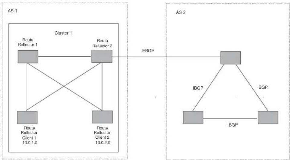
flowchart
graph TD
subgraph AS 1
A["Route Reflector 1"] --> B["Route Reflector 2"]
C["Route Reflector Client 1 10.0.1.0"] --> A
D["Route Reflector Client 2 10.0.2.0"] --> B
end
subgraph AS 2
E["IBGP"] --> F["IBGP"]
F --> G["IBGP"]
G --> H["IBGP"]
end
A --> C
A --> D
A --> E
B --> F
B --> G
B --> H
style AS 1 fill:#f9f,stroke:#333
style AS 2 fill:#ccf,stroke:#333
Support for RFC 2796
Route reflection is based on RFC 2796. This updated RFC helps eliminate routing loops that are possible in some implementations of the older specification, RFC 1966.
- The device adds the route reflection attributes only if it is a route reflector, and only when advertising IBGP route information to other IBGP neighbors. The attributes are not used when communicating with EBGP neighbors.
-
A device configured as a route reflector sets the ORIGINATOR_ID attribute to the router ID of the router that originated the route. Moreover, the route reflector sets the attribute only if this is the first time the route is being reflected (sent by a route reflector).
-
If a device receives a route whose ORIGINATOR_ID attribute has the value of the device's own router ID, the device discards the route and does not advertise it. By discarding the route, the device prevents a routing loop.
- The first time a route is reflected by a device configured as a route reflector, the route reflector adds the CLUSTER_LIST attribute to the route. Other route reflectors who receive the route from an IBGP neighbor add their cluster IDs to the front of the route's CLUSTER_LIST. If the route reflector does not have a cluster ID configured, the device adds its router ID to the front of the CLUSTER_LIST.
- If the device configured as a route reflector receives a route whose CLUSTER_LIST contains the route reflector's own cluster ID, the route reflector discards the route and does not forward it.
Configuration procedures
NOTE
All configuration for route reflection takes place on the route reflectors, not on the clients.
Enter the following commands to configure a device as route reflector 1 in Figure 26.4 on page 26-42. To configure route reflector 2, enter the same commands on the device that will be route reflector 2. The clients require no configuration for route reflection.
BigIron RX(config-bgp)# cluster-id 1
BigIron RX(config-bgp)# neighbor 10.0.1.0 route-reflector-client
BigIron RX(config-bgp)# neighbor 10.0.2.0 route-reflector-client
Syntax: [no] cluster-id
The
NOTE
If the cluster contains more than one route reflector, you need to configure the same cluster ID on all the route reflectors in the cluster. The cluster ID helps route reflectors avoid loops within the cluster.
To add an IBGP neighbor to the cluster, enter the following command.
Syntax: neighbor
For more information about the neighbor command, refer to "Configuring BGP4 neighbors" on page 771 and "Configuring a BGP4 peer group" on page 778.
Filtering
This section describes the following:
• "Filtering AS-paths" on page 795
• "Filtering communities" on page 798
- “Defining and applying IP prefix lists” on page 799
- “Defining neighbor distribute lists” on page 800
- "Defining route maps" on page 801
• "Using a table map to set the tag value" on page 789
- "Configuring cooperative BGP4 route filtering" on page 809
Filtering AS-paths
You can filter updates received from BGP4 neighbors based on the contents of the AS-path list accompanying the updates. For example, if you want to deny routes that have the AS 4.3.2.1 in the AS-path from entering the BGP4 route table, you can define a filter to deny such routes.
The device provides the following methods for filtering on AS-path information:
- AS-path filters - refer to "Defining an AS-path filter" on page 753.
- AS-path ACLs
NOTE
The BigIron RX cannot actively support AS-path filters and AS-path ACLs at the same time. Use one method or the other but do not mix methods.
NOTE
Once you define a filter or ACL, the default action for updates that do not match a filter is “deny”. To change the default action to “permit”, configure the last filter or ACL as “permit any any”.
AS-path filters or AS-path ACLs can be referred to by a BGP neighbor's filter list number as well as by match statements in a route map.
Defining an AS-path ACL
To configure an AS-path list that uses ACL 1, enter a command such as the following.
BigIron RX(config)# ip as-path access-list acl1 permit 100
BigIron RX(config)# router bgp
BigIron RX(config-bgp)# neighbor 10.10.10.1 filter-list 1 in
The ip as-path command configures an AS-path ACL that permits routes containing AS number 100 in their AS paths. The neighbor command then applies the AS-path ACL to advertisements and updates received from neighbor 10.10.10.1. In this example, the only routes the device permits from neighbor 10.10.10.1 are those whose AS-paths contain AS-path number 100.
Syntax: ip as-path access-list
The
The seq
The deny | permit parameter specifies the action the software takes if a route's AS-path list matches a match statement in this ACL. To configure the AS-path match statements in a route map, use the match as-path command. Refer to "Matching based on AS-path ACL" on page 804.
The
The neighbor command uses the filter-list parameter to apply the AS-path ACL to the neighbor. Refer to "Configuring BGP4 neighbors" on page 771 and "Configuring a BGP4 peer group" on page 778.
Using regular expressions
You use a regular expression for the
In addition, you can include special characters that influence the way the software matches the AS-path against the filter value.
To filter on a specific single-character value, enter the character for the
BigIron RX(config-bgp)# ip as-path access-list acl1 permit z
To filter on a string of multiple characters, enter the characters in brackets. For example, to filter on AS-paths that contain "x", "y", or "z", enter the following command.
BigIron RX(config-bgp)# ip as-path access-list acl1 permit [xyz]
Special characters
When you enter as single-character expression or a list of characters, you also can use the following special characters. Table 26.2 on page 26-45 lists the special characters. The description for each special character includes an example. Notice that you place some special characters in front of the characters they control but you place other special characters after the characters they control. In each case, the examples show where to place the special character.
TABLE 122 BGP4 special characters for regular expressions
| Character Operation |
| . The period matches on any single character, including a blank space. For example, the following regular expression matches for “aa”, “ab”, “ac”, and so on, but not just “a”.a. |
| * The asterisk matches on zero or more sequences of a pattern. For example, the following regular expression matches on an AS-path that contains the string “1111” followed by any value.1111* |
| + The plus sign matches on one or more sequences of a pattern. For example, the following regular expression matches on an AS-path that contains a sequence of “g”s, such as “deg”, “degg”, “deggg”, and so on.deg+ |
| ? The question mark matches on zero occurrences or one occurrence of a pattern. For example, the following regular expression matches on an AS-path that contains “dg” or “deg”.de?g |
| ^ A caret (when not used within brackets) matches on the beginning of an input string. For example, the following regular expression matches on an AS-path that begins with “3”.^3 |
\$ A dollar sign matches on the end of an input string. For example, the following regular expression matches on an AS-path that ends with "deg". deg\$
TABLE 122 BGP4 special characters for regular expressions (Continued)
| Character Operation | |
| - | An underscore matches on one or more of the following:• , (comma)• { (left curly brace)• } (right curly brace)• ( (left parenthesis)• ) (right parenthesis)• The beginning of the input string• The end of the input string• A blank spaceFor example, the following regular expression matches on “100” but not on “1002”, “2100”, and so on._100_ |
| [ ] | Square brackets enclose a range of single-character patterns. For example, the following regular expression matches on an AS-path that contains “1”, “2”, “3”, “4”, or “5”.[1-5]You can use the following expression symbols within the brackets. These symbols are allowed only inside the brackets.ˆ - The caret matches on any characters except the ones in the brackets. For example, the following regular expression matches on an AS-path that does not contain “1”, “2”, “3”, “4”, or “5”.[^1-5]- The hyphen separates the beginning and ending of a range of characters. A match occurs if any of the characters within the range is present. See the example above. |
| I | A vertical bar (sometimes called a pipe or a “logical or”) separates two alternative values or sets of values. The AS-path can match one or the other value. For example, the following regular expression matches on an AS-path that contains either “abc” or “defg”.(abc)|(defg)NOTE: The parentheses group multiple characters to be treated as one value. See the following row for more information about parentheses. |
| ( ) Parentheses allow you to create complex expressions. For example, the following complex expression matches on “abc”, “abcabc”, or “abcabcabcdefg”, but not on “abcdefgdefg”.((abc)+)|(defg)?) | |
If you want to filter for a special character instead of using the special character as described in Table 26.2 on page 26-45, enter “\” (backslash) in front of the character. For example, to filter on AS-path strings containing an asterisk, enter the asterisk portion of the regular expression as “*”.
BigIron RX(config-bgp)# ip as-path access-list acl2 deny *
To use the backslash as a string character, enter two slashes. For example, to filter on AS-path strings containing a backslash, enter the backslash portion of the regular expression as “\”.
BigIron RX(config-bgp)# ip as-path access-list acl2 deny \
Filtering communities
You can filter routes received from BGP4 neighbors based on community names.
A community is an optional attribute that identifies the route as a member of a user-defined class of routes. Community names are arbitrary values made of two five-digit integers joined by a colon. You determine what the name means when you create the community name as one of a route's attributes. Each string in the community name can be a number from 0 - 65535.
This format allows you to easily classify community names. For example, a common convention used in community naming is to configure the first string as the local AS and the second string as the unique community within that AS. Using this convention, communities 1:10, 1:20, and 1:30 can be easily identified as member communities of AS 1.
The BigIron RX provides the following methods for filtering on community information:
- Community filters - refer to "Defining a community filter" on page 753.
• Community list ACLs
NOTE
The BigIron RX cannot actively support community filters and community list ACLs at the same time. Use one method or the other but do not mix methods.
NOTE
Once you define a filter or ACL, the default action for communities that do not match a filter or ACL is “deny”. To change the default action to “permit”, configure the last filter or ACL entry as “permit any any”.
Community filters or ACLs can be referred to by match statements in a route map.
Defining a community ACL
To configure community ACL 1, enter a command such as the following.
BigIron RX(config)# ip community-list 1 permit 123:2
This command configures a community ACL that permits routes that contain community 123:2.
NOTE
Refer to “Matching based on community ACL” on page 804 for information about how to use a community list as a match condition in a route map.
Syntax: ip community-list standard
Syntax: ip community-list extended
The
The standard or extended parameter specifies whether you are configuring a standard community ACL or an extended one. A standard community ACL does not support regular expressions whereas an extended one does. This is the only difference between standard and extended IP community lists.
The seq
The deny | permit parameter specifies the action the software takes if a route's community list matches a match statement in this ACL. To configure the community-list match statements in a route map, use the match community command. Refer to “Matching based on community ACL” on page 804
The
: - A specific community number - internet – The Internet community
- no-export – The community of sub-ASs within a confederation. Routes with this community can be exported to other sub-ASs within the same confederation but cannot be exported outside the confederation to other ASs or otherwise sent to EBGP neighbors.
- local-as – The local sub-AS within the confederation. Routes with this community can be advertised only within the local subAS.
- no-advertise – Routes with this community cannot be advertised to any other BGP4 routers at all.
The
To use a community-list filter, use route maps with the match community parameter.
Defining and applying IP prefix lists
An IP prefix list specifies a list of networks. When you apply an IP prefix list to a neighbor, the device sends or receives only a route whose destination is in the IP prefix list. The software interprets the prefix lists in order, beginning with the lowest sequence number.
To configure an IP prefix list and apply it to a neighbor, enter commands such as the following.
BigIron RX(config)# ip prefix-list Routesfor20 permit 20.20.0.0/24
BigIron RX(config)# router bgp
BigIron RX(config-bgp)# neighbor 10.10.10.1 prefix-list Routesfor20 out
These commands configure an IP prefix list named Routesfor20, which permits routes to network 20.20.0.0/24. The neighbor command configures the device to use IP prefix list Routesfor20 to determine which routes to send to neighbor 10.10.10.1. The device sends routes that go to 20.20.x.x to neighbor 10.10.10.1 because the IP prefix list explicitly permits these routes to be sent to the neighbor.
Syntax: ip prefix-list
The
The description
The seq
The deny | permit parameter specifies the action the software takes if a neighbor's route is in this prefix list.
The prefix-list matches only on this network unless you use the ge
The
You can specify a range of prefix length for prefixes that are more specific than
- If you specify only ge
, then the mask-length range is from to 32. - If you specify only le
, then the mask-length range is from length to .
The
length < ge-value <= le-value <= 32
If you do not specify ge
For the syntax of the neighbor command shown in the example above, refer to “Configuring BGP4 neighbors” on page 771 and “Configuring a BGP4 peer group” on page 778.
Defining neighbor distribute lists
A neighbor distribute list is a list of BGP4 address filters or ACLs that filter the traffic to or from a neighbor.
To configure a distribute list that uses ACL 1, enter a command such as the following.
BigIron RX(config-bgp)# neighbor 10.10.10.1 distribute-list 1 in
This command configures the device to use ACL 1 to select the routes that the device will accept from neighbor 10.10.10.1.
Syntax: neighbor
The
The
The in | out parameter specifies whether the distribute list applies to inbound or outbound routes.
- in – controls the routes the device will accept from the neighbor.
- out – controls the routes sent to the neighbor.
Defining route maps
A route map is a named set of match conditions and parameter settings that the router can use to modify route attributes and to control redistribution of the routes into other protocols. A route map consists of a sequence of instances. If you think of a route map as a table, an instance is a row in that table. The router evaluates a route according to a route map's instances in ascending numerical order. The route is first compared against instance 1, then against instance 2, and so on. As soon as a match is found, the router stops evaluating the route against the route map instances.
Route maps can contain match statements and set statements. Each route map contains a "permit" or "deny" action for routes that match the match statements.
- If the route map contains a permit action, a route that matches a match statement is permitted; otherwise, the route is denied.
- If the route map contains a deny action, a route that matches a match statement is denied.
- If a route does not match any match statements in the route map, the route is denied. This is the default action. To change the default action, configure the last match statement in the last instance of the route map to "permit any any.".
- If there is no match statement, the software considers the route to be a match.
- For route maps that contain address filters, AS-path filters, or community filters, if the action specified by a filter conflicts with the action specified by the route map, the route map's action takes precedence over the individual filter's action.
If the route map contains set statements, routes that are permitted by the route map's match statements are modified according to the set statements.
Match statements compare the route against one or more of the following:
- The route's BGP4 MED (metric)
• A sequence of AS-path filters
• A sequence of community filters
• A sequence of address filters - The IP address of the next hop router
- The route's tag
- For OSPF routes only, the route's type (internal, external type-1, or external type-2)
- An AS-path ACL
- A community ACL
- An IP prefix list
• An IP ACL
For routes that match all of the match statements, the route map's set statements can perform one or more of the following modifications to the route's attributes:
- Prepend AS numbers to the front of the route's AS-path. By adding AS numbers to the AS-path, you can cause the route to be less preferred when compared to other routes on the basis of the length of the AS-path.
- Add a user-defined tag to the route or add an automatically calculated tag to the route.
- Set the community value.
-
Set the local preference.
-
Set the MED (metric).
- Set the IP address of the next hop router.
- Set the origin to IGP or INCOMPLETE.
- Set the weight.
For example, when you configure parameters for redistributing routes into BGP, one of the optional parameters is a route map. If you specify a route map as one of the redistribution parameters, the router will match the route against the match statements in the route map. If a match is found and if the route map contains set statements, the router will set attributes in the route according to the set statements.
To create a route map, you define instances of the map. Each instance is identified by a sequence number.
To define a route map, use the procedures in the following sections.
Entering the route map Into the software
To add instance 1 of a route map named "GET_ONE" with a permit action, enter the following command.
BigIron RX(config)# route-map GET_ONE permit 1 BigIron RX(config-routemap GET_ONE)#
Syntax: [no] route-map
As shown in this example, the command prompt changes to the Route Map level. You can enter the match and set statements at this level. Refer to "Specifying the match conditions" on page 803 and "Setting parameters in the routes" on page 806.
The
The permit | deny parameter specifies the action the router will take if a route matches a match statement.
- If you specify deny, the device does not advertise or learn the route.
- If you specify permit, the device applies the match and set statements associated with this route map instance.
The
To delete a route map, enter a command such as the following. When you delete a route map, all the permit and deny entries in the route map are deleted.
BigIron RX(config)# no route-map Map1
This command deletes a route map named "Map1". All entries in the route map are deleted.
To delete a specific instance of a route map without deleting the rest of the route map, enter a command such as the following.
BigIron RX(config)# no route-map Map1 permit 10
This command deletes the specified instance from the route map but leaves the other instances of the route map intact.
Specifying the match conditions
Use the following command to define the match conditions for instance 1 of the route map GET_ONE. This instance compares the route updates against BGP4 address filter 11.
BigIron RX(config-routemap GET_ONE)# match address-filters 11
Syntax: match
[as-path <name>] |
[address-filters | as-path-filters | community-filters <num,num,...>] |
[community <acl> exact-match] |
[ip address <acl> | prefix-list <string>] |
[ip route-source <acl> | prefix <name>]
[metric <num>] |
[next-hop <address-filter-list>] |
[route-type internal | external-type1 | external-type2] | [level-1 | level-2 | level-1-2]
[tag <tag-value>]
The as-path
The address-filters | as-path-filters | community-filters
- To configure an address filter, refer to "Filtering specific IP addresses" on page 751.
- To configure an AS-path filter or AS-path ACL, refer to "Filtering AS-paths" on page 795.
- To configure a community filter or community ACL, refer to “Filtering communities” on page 798.
You can enter up to six community names on the same command line.
NOTE
The filters must already be configured.
The community
NOTE
The ACL must already be configured.
The community
The ip address | next-hop
The ip route-source
The metric
The next-hop
The route-type internal | external-type1 | external-type2 parameter applies only to OSPF routes. This parameter compares the route's type to the specified value. The level-1 parameter compares ISIS routes only with routes within the same area. The level-2 parameter compares ISIS routes only with routes in different areas, but within a domain. The level-1-2 parameter compares ISIS routes with routes the same area and in different areas, but within a domain.
The tag
The following sections are some examples of how to configure route maps that include match statements that match on ACLs.
Matching based on AS-path ACL
To construct a route map that matches based on AS-path ACL 1, enter the following commands.
BigIron RX(config)# route-map PathMap permit 1
BigIron RX(config-routemap PathMap)# match as-path 1
Syntax: match as-path
The
Matching based on community ACL
To construct a route map that matches based on community ACL 1, enter the following commands.
BigIron RX(config)# ip community-list 1 permit 123:2
BigIron RX(config)# route-map CommMap permit 1
BigIron RX(config-routemap CommMap)# match community 1
Syntax: match community
The
Matching based on destination network
You can use the results of an IP ACL or an IP prefix list as the match condition.
To construct a route map that matches based on destination network, enter commands such as the following.
BigIron RX(config)# route-map NetMap permit 1
BigIron RX(config-routemap NetMap)# match ip address 1
Syntax: match ip address
Syntax: match ip address prefix-list
The
The
Matching based on next-hop router
You can use the results of an IP ACL or an IP prefix list as the match condition.
To construct a route map that matches based on the next-hop router, enter commands such as the following.
BigIron RX(config)# route-map HopMap permit 1
BigIron RX(config-routemap HopMap)# match ip next-hop 2
Syntax: match ip next-hop
Syntax: match ip next-hop prefix-list
The
The
Matching based on the route source
To match a BGP4 route based on its source, use the match ip route-source statement. Here is an example.
BigIron RX(config)# access-list 10 permit 192.168.6.0 0.0.0.255
BigIron RX(config)# route-map bgp1 permit 1
BigIron RX(config-routemap bgp1)# match ip route-source 10
The first command configures an IP ACL that matches on routes received from 192.168.6.0/24. The remaining commands configure a route map that matches on all BGP4 routes advertised by the BGP4 neighbors whose addresses match addresses in the IP prefix list. You can add a set statement to change a route attribute in the routes that match. You also can use the route map as input for other commands, such as the neighbor and network commands and some show commands.
Syntax: match ip route-source
The
Matching on routes containing a specific set of communities
BigIron RX enables you to match routes based on the presence of a community name or number in a route. To match based on a set of communities, configure a community ACL that lists the communities, then compare routes against the ACL.
Here is an example.
BigIron RX(config)# ip community-list standard std_1 permit 12:34 no-export
BigIron RX(config)# route-map bgp2 permit 1
BigIron RX(config-routemap bgp2)# match community std_1 exact-match
The first command configures a community ACL that contains community number 12:34 and community name no-export. The remaining commands configure a route map that matches the community attributes field in BGP4 routes against the set of communities in the ACL. A route matches the route map only if the route contains all the communities in the ACL and no other communities.
Syntax: match community
The
Here is another example.
BigIron RX(config)# ip community-list standard std_2 permit 23:45 56:78
BigIron RX(config)# route-map bgp3 permit 1
BigIron RX(config-routemap bgp3)# match community std_1 std_2 exact-match
These commands configure an additional community ACL, std_2, that contains community numbers 23:45 and 57:68. Route map bgp3 compares each BGP4 route against the sets of communities in ACLs std_1 and std_2. A BGP4 route that contains either but not both sets of communities matches the route map. For example, a route containing communities 23:45 and 57:68 matches. However, a route containing communities 23:45, 57:68 and 12:34, or communities 23:45, 57:68, 12:34, and no-export does not match. To match, the route's communities must be the same as those in exactly one of the community ACLs used by the match community statement.
Setting parameters in the routes
Use the following command to define a set statement that prepends an AS number to the AS path on each route that matches the corresponding match statement.
BigIron RX(config-routemap GET_ONE)# set as-path prepend 65535
Syntax: set
[as-path [prepend <as-num, as-num,...>]] |
[automatic-tag] |
[comm-list <acl> delete] |
[community <num>:<num> | <num> | internet | local-as | no-advertise | no-export] |
[dampening [<half-life> <reuse> <suppress> <max-suppress-time>]]
[ip next hop <ip-addr>]
[ip next-hop peer-address] |
[local-preference <num>] |
[metric [+ | - ]<num> | none] |
[metric-type type-1 | type-2] | external
[metric-type internal] |
[next-hop <ip-addr>] |
[origin igp | incomplete] |
[tag <tag-value>] |
[weight <num>]
The as-path prepend
The automatic-tag parameter calculates and sets an automatic tag value for the route.
NOTE
This parameter applies only to routes redistributed into OSPF.
The comm-list parameter deletes a community from a BGP4 route's community attributes field.
The community parameter sets the community attribute for the route to the number or well-known type you specify.
The dampening [
The ip next hop
The ip next-hop peer-address parameter sets the BGP4 next hop for a route to the neighbor address.
The local-preference
The metric [+ | -] < num> | none parameter sets the MED (metric) value for the route. The default MED value is 0. You can set the preference to a value from 0 - 4294967295.
- set metric
- Sets the route's metric to the number you specify. - set metric +
- Increases route's metric by the number you specify. - set metric -
– Decreases route's metric by the number you specify. - set metric none – Removes the metric from the route (removes the MED attribute from the BGP4 route).
The metric-type type-1 | type-2 parameter changes the metric type of a route redistributed into OSPF.
The metric-type internal parameter sets the route's MED to the same value as the IGP metric of the BGP4 next-hop route. The parameter does this when advertising a BGP4 route to an EBGP neighbor.
The next-hop
The origin igp | incomplete parameter sets the route's origin to IGP or INCOMPLETE.
The tag
NOTE
This parameter applies only to routes redistributed into OSPF.
NOTE
You also can set the tag value using a table map. The table map changes the value only when the device places the route in the IP route table instead of changing the value in the BGP route table. Refer to "Using a table map to set the tag value" on page 789.
The weight
Setting a BP4 route's MED to be equal to the next-hop route IGP metric
To set a route's MED to the same value as the IGP metric of the BGP4 next-hop route, when advertising the route to a neighbor, enter commands such as the following.
BigIron RX(config)# access-list 1 permit 192.168.9.0 0.0.0.255 BigIron RX(config)# route-map bgp4 permit 1 BigIron RX(config-routemap bgp4)# match ip address 1 BigIron RX(config-routemap bgp4)# set metric-type internal
The first command configures an ACL that matches on routes with destination network 192.168.9.0. The remaining commands configure a route map that matches on the destination network in ACL 1, then sets the metric type for those routes to the same value as the IGP metric of the BGP4 next-hop route.
Syntax: set metric-type internal
Setting the next hop of a BGP4 route
To set the next hop address of a BGP4 route to a neighbor address, enter commands such as the following.
BigIron RX(config)# route-map bgp5 permit 1 BigIron RX(config-routemap bgp5)# match ip address 1 BigIron RX(config-routemap bgp5)# set ip next-hop peer-address
These commands configure a route map that matches on routes whose destination network is specified in ACL 1, and sets the next hop in the routes to the neighbor address (inbound filtering) or the local IP address of the BGP4 session (outbound filtering).
Syntax: set ip next-hop peer-address
The value that the software substitutes for peer-address depends on whether the route map is used for inbound filtering or outbound filtering:
- When you use the set ip next-hop peer-address command in an inbound route map filter, peer-address substitutes for the neighbor's IP address.
- When you use the set ip next-hop peer-address command in an outbound route map filter, peer-address substitutes for the local IP address of the BGP4 session.
NOTE
You can use this command for a peer group configuration.
Deleting a community from a BGP4 route
To delete a community from a BGP4 route's community attributes field, enter commands such as the following.
BigIron RX(config)# ip community-list standard std_3 permit 12:99 12:86 BigIron RX(config)# route-map bgp6 permit 1 BigIron RX(config-routemap bgp6)# match ip address 1 BigIron RX(config-routemap bgp6)# set comm-list std_3 delete
The first command configures a community ACL containing community numbers 12:99 and 12:86. The remaining commands configure a route map that matches on routes whose destination network is specified in ACL 1, and deletes communities 12:99 and 12:86 from those routes. The route does not need to contain all the specified communities in order for them to be deleted. For example, if a route contains communities 12:86, 33:44, and 66:77, community 12:86 is deleted.
Syntax: set comm-list
The
Configuring cooperative BGP4 route filtering
By default, the device performs all filtering of incoming routes locally, on the device itself. You can use cooperative BGP4 route filtering to cause the filtering to be performed by a neighbor before it sends the routes to the device. Cooperative filtering conserves resources by eliminating unnecessary route updates and filter processing. For example, the device can send a deny filter to its neighbor, which the neighbor uses to filter out updates before sending them to the device. The neighbor saves the resources it would otherwise use to generate the route updates, and the device saves the resources it would use to filter out the routes.
When you enable cooperative filtering, the device advertises this capability in its Open message to the neighbor when initiating the neighbor session. The Open message also indicates whether the device is configured to send filters, receive filters or both, and the types of filters it can send or receive. The device sends the filters as Outbound Route Filters (ORFs) in Route Refresh messages.
To configure cooperative filtering, perform the following tasks on the device and on its BGP4 neighbor:
- Configure the filter.
NOTE
The current release supports cooperative filtering only for filters configured using IP prefix lists.
- Apply the filter as in inbound filter to the neighbor.
- Enable the cooperative route filtering feature on the device. You can enable the device to send ORFs to the neighbor, to receive ORFs from the neighbor, or both. The neighbor uses the ORFs you send as outbound filters when it sends routes to the device. Likewise, the device uses the ORFs it receives from the neighbor as outbound filters when sending routes to the neighbor.
- Reset the BGP4 neighbor session to send and receive ORFs.
- Perform these steps on the other device.
NOTE
If the device has inbound filters, the filters are still processed even if equivalent filters have been sent as ORFs to the neighbor.
Enabling cooperative filtering
To configure cooperative filtering, enter commands such as the following.
BigIron RX(config)# ip prefix-list Routesfrom1234 deny 20.20.0.0/24 BigIron RX(config)# ip prefix-list Routesfrom1234 permit 0.0.0.0/0 le 32 BigIron RX(config)# router bgp BigIron RX(config-bgp)# neighbor 1.2.3.4 prefix-list Routesfrom1234 in BigIron RX(config-bgp)# neighbor 1.2.3.4 capability orf prefixlist send
The first two commands configure statements for the IP prefix list Routesfrom1234. The first command configures a statement that denies routes to 20.20.20./24. The second command configures a statement that permits all other routes. (Once you configure an IP prefix list statement, all routes not explicitly permitted by statements in the prefix list are denied.)
The next two commands change the CLI to the BGP4 configuration level, then apply the IP prefix list to neighbor 1.2.3.4. The last command enables the device to send the IP prefix list as an ORF to neighbor 1.2.3.4. When the device sends the IP prefix list to the neighbor, the neighbor filters out the 20.20.0.x routes from its updates to the device. (This assumes that the neighbor also is configured for cooperative filtering.)
Syntax: [no] neighbor
The
The send | receive parameter specifies the support you are enabling:
- send – The device sends the IP prefix lists to the neighbor.
- receive – The device accepts filters from the neighbor.
If you do not specify the capability, both capabilities are enabled.
The prefixlist parameter specifies the type of filter you want to send to the neighbor.
NOTE
The current release supports cooperative filtering only for filters configured using IP prefix lists.
Sending and receiving ORFs
Cooperative filtering affects neighbor sessions that start after the filtering is enabled, but do not affect sessions that are already established.
To activate cooperative filtering, reset the session with the neighbor. This is required because the cooperative filtering information is exchanged in Open messages during the start of a session.
To place a prefix-list change into effect after activating cooperative filtering, perform a soft reset of the neighbor session. A soft reset does not end the current session, but sends the prefix list to the neighbor in the next route refresh message.
NOTE
Make sure cooperative filtering is enabled on the device and on the neighbor before you send the filters.
To reset a neighbor session and send ORFs to the neighbor, enter a command such as the following.
BigIron RX# clear ip bgp neighbor 1.2.3.4
This command resets the BGP4 session with neighbor 1.2.3.4 and sends the ORFs to the neighbor. If the neighbor sends ORFs to the device, the device accepts them if the send capability is enabled.
To perform a soft reset of a neighbor session and send ORFs to the neighbor, enter a command such as the following.
BigIron RX# clear ip bgp neighbor 1.2.3.4 soft in prefix-list
Syntax: clear ip bgp neighbor
If you use the soft in prefix-filter parameter, the device sends the updated IP prefix list to the neighbor as part of its route refresh message to the neighbor.
NOTE
If the device or the neighbor is not configured for cooperative filtering, the command sends a normal route refresh message.
Displaying cooperative filtering information
You can display the following cooperative filtering information:
- The cooperative filtering configuration on the device.
• The ORFs received from neighbors.
To display the cooperative filtering configuration on the device, enter a command such as the following. The line shown in bold type shows the cooperative filtering status.
BigIron RX# show ip bgp neighbor 10.10.10.1
IP Address: 10.10.10.1, AS: 65200 (IBGP), RouterID: 10.10.10.1
State: ESTABLISHED, Time: 0h0m7s, KeepAliveTime: 60, HoldTime: 180
RefreshCapability: Received
CooperativeFilteringCapability: Received
Messages: Open Update KeepAlive Notification Refresh-Req
Sent : 1 0 1 0 1
Received: 1 0 1 0 1
Last Update Time: NLRI Withdraw NLRI Withdraw
Tx: --- --- Rx: --- ---
Last Connection Reset Reason:Unknown
Notification Sent: Unspecified
Notification Received: Unspecified
TCP Connection state: ESTABLISHED
Byte Sent: 110, Received: 110
Local host: 10.10.10.2, Local Port: 8138
Remote host: 10.10.10.1, Remote Port: 179
ISentSeq: 460 SendNext: 571 TotUnAck: 0
TotSent: 111 ReTrans: 0 UnAckSeq: 571
IRcvSeq: 7349 RcvNext: 7460 SendWnd: 16384
TotalRcv: 111 DupliRcv: 0 RcvWnd: 16384
SendQue: 0 RcvQue: 0 CngstWnd: 5325
Syntax: show ip bgp neighbor
To display the ORFs received from a neighbor, enter a command such as the following.
3igIron RX# show ip bgp neighbor 10.10.10.1 received prefix-filter
ip prefix-list 10.10.10.1: 4 entries
seq 5 permit 10.10.0.0/16 ge 18 le 28
seq 10 permit 20.20.10.0/24
seq 15 permit 30.0.0.0/8 le 32
seq 20 permit 40.10.0.0/16 ge 18
Syntax: show ip bgp neighbor
Configuring route flap dampening
A “route flap” is the change in a route’s state, from up to down or down to up. When a route’s state changes, the state change causes changes in the route tables of the routers that support the route. Frequent changes in a route’s state can cause Internet instability and add processing overhead to the routers that support the route.
Route flap dampening is a mechanism that reduces the impact of route flap by changing a BGP4 router's response to route state changes. When route flap dampening is configured, the device suppresses unstable routes until the route's state changes reduce enough to meet an acceptable degree of stability. The Brocade implementation of route flap dampening is based on RFC 2439.
Route flap dampening is disabled by default. You can enable the feature globally or on an individual route basis using route maps.
NOTE
The BigIron RX applies route flap dampening only to routes learned from EBGP neighbors.
The route flap dampening mechanism is based on penalties. When a route exceeds a configured penalty value, the device stops using that route and also stops advertising it to other routers. The mechanism also allows a route's penalties to reduce over time if the route's stability improves. The route flap dampening mechanism uses the following parameters:
- Suppression threshold – Specifies the penalty value at which the device stops using the route. Each time a route becomes unreachable or is withdrawn by a BGP4 UPDATE from a neighbor, the route receives a penalty of 1000. By default, when a route has a penalty value greater than 2000, the device stops using the route. Thus, by default, if a route goes down more than twice, the device stops using the route. You can set the suppression threshold to a value from 1 – 20000. The default is 2000.
- Half-life – Once a route has been assigned a penalty, the penalty decreases exponentially and decreases by half after the half-life period. The default half-life period is 15 minutes. The software reduces route penalties every five seconds. For example, if a route has a penalty of 2000 and does not receive any more penalties (it does not go down again) during the half-life, the penalty is reduced to 1000 after the half-life expires. You can configure the half-life to be from 1 – 45 minutes. The default is 15 minutes.
- Reuse threshold – Specifies the minimum penalty a route can have and still be suppressed by the device. If the route's penalty falls below this value, the device un-suppresses the route and can use it again. The software evaluates the dampened routes every ten seconds and un-suppresses the routes that have penalties below the reuse threshold. You can set the reuse threshold to a value from 1 - 20000. The default is 750.
- Maximum suppression time – Specifies the maximum number of minutes a route can be suppressed regardless of how unstable the route has been before this time. You can set the parameter to a value from 1 – 20000 minutes. The default is four times the half-life. When the half-life value is set to its default (15 minutes), the maximum suppression time defaults to 60 minutes.
You can configure route flap dampening globally or for individual routes using route maps. If you configure route flap dampening parameters globally and also use route maps, the settings in the route maps override the global values.
Using a route map to configure route flap dampening for specific routes
Route maps enable you to fine tune route flap dampening parameters for individual routes. To configure route flap dampening parameters using route maps, configure BGP4 address filters for each route you want to set the dampening parameters for, then configure route map entries that set the dampening parameters for those routes. The following sections show examples.
To configure address filters and a route map for dampening specific routes, enter commands such as the following.
BigIron RX(config)# router bgp
BigIron RX(config-bgp)# address-filter 9 permit 209.157.22.0 255.255.255.0
255.255.255.0 255.255.255.0
BigIron RX(config-bgp)# address-filter 10 permit 209.157.23.0 255.255.255.0
255.255.255.0 255.255.255.0
BigIron RX(config-bgp)# exit
BigIron RX(config)# route-map DAMPENING_MAP permit 9
BigIron RX(config-routemap DAMPENING_MAP)# match address-filters 9
BigIron RX(config-routemap DAMPENING_MAP)# set dampening 10 200 2500 40
BigIron RX(config-routemap DAMPENING_MAP)# exit
BigIron RX(config)# route-map DAMPENING_MAP permit 10
BigIron RX(config-routemap DAMPENING_MAP)# match address-filters 10
BigIron RX(config-routemap DAMPENING_MAP)# set dampening 20 200 2500 60
BigIron RX(config-routemap DAMPENING_MAP)# router bgp
BigIron RX(config-bgp)# dampening route-map DAMPENING_MAP
The address-filter commands in this example configure two BGP4 address filters, for networks 209.157.22.0 and 209.157.23.0. The first route-map command creates an entry in a route map called "DAMPENING_MAP". Within this entry of the route map, the match command matches based on address filter 9, and the set command sets the dampening parameters for the route that matches. Thus, for BGP4 routes to 209.157.22.0, the device uses the route map to set the dampening parameters. These parameters override the globally configured dampening parameters.
The commands for the second entry in the route map (instance 10 in this example) perform the same functions for route 209.157.23.0. Notice that the dampening parameters are different for each route.
Using a route map to configure route flap dampening for a specific neighbor
You can use a route map to configure route flap dampening for a specific neighbor by performing the following tasks:
- Configure an empty route map with no match or set statements. This route map does not specify particular routes for dampening but does allow you to enable dampening globally when you refer to this route map from within the BGP configuration level.
- Configure another route map that explicitly enables dampening. Use a set statement within the route map to enable dampening. When you associate this route map with a specific neighbor, the route map enables dampening for all routes associated with the neighbor. You also can use match statements within the route map to selectively perform dampening on some routes from the neighbor.
NOTE
You still need to configure the first route map to enable dampening globally. The second route map does not enable dampening by itself; it just applies dampening to a neighbor.
- Apply the route map to the neighbor.
To enable route flap dampening for a specific BGP4 neighbor, enter commands such as the following.
BigIron RX(config)# route-map DAMPENING_MAP_ENABLE permit 1
BigIron RX(config-routemap DAMPENING_MAP_ENABLE)# exit
BigIron RX(config)# route-map DAMPENING_MAP_NEIGHBOR_A permit 1
BigIron RX(config-routemap DAMPENING_MAP_NEIGHBOR_A)# set dampening
BigIron RX(config-routemap DAMPENING_MAP_NEIGHBOR_A)# exit
BigIron RX(config)# router bgp
BigIron RX(config-bgp)# dampening route-map DAMPENING_MAP_ENABLE
BigIron RX(config-bgp)# neighbor 10.10.10.1 route-map in DAMPENING_MAP_NEIGHBOR_A
In this example, the first command globally enables route flap dampening. This route map does not contain any match or set statements. At the BGP configuration level, the dampening route-map command refers to the DAMPENING_MAP_ENABLE route map created by the first command, thus enabling dampening globally.
The third and fourth commands configure a second route map that explicitly enables dampening. Notice that the route map does not contain a match statement. The route map implicitly applies to all routes. Since the route map will be applied to a neighbor at the BGP configuration level, the route map will apply to all routes associated with the neighbor.
Although the second route map enables dampening, the first route map is still required. The second route map enables dampening for the neighbors to which the route map is applied. However, unless dampening is already enabled globally by the first route map, the second route map has no effect.
The last two commands apply the route maps. The dampening route-map command applies the first route map, which enables dampening globally. The neighbor command applies the second route map to neighbor 10.10.10.1. Since the second route map does not contain match statements for specific routes, the route map enables dampening for all routes received from the neighbor.
Removing route dampening from a route
You can un-suppress routes by removing route flap dampening from the routes. The BigIron RX allows you to un-suppress all routes at once or un-suppress individual routes.
To un-suppress all the suppressed routes, enter the following command at the Privileged EXEC level of the CLI.
BigIron RX# clear ip bgp damping
Syntax: clear ip bgp damping [
The
The
To un-suppress a specific route, enter a command such as the following.
BigIron RX# clear ip bgp damping 209.157.22.0 255.255.255.0
This command un-suppresses only the routes for network 209.157.22.0/24.
Displaying and clearing route flap dampening statistics
The software provides many options for displaying and clearing route flap statistics.
Displaying route flap dampening statistics
To display route dampening statistics or all the dampened routes, enter the following command at any level of the CLI.
| BigIron RX# show ip bgp flap-statistics | ||||||||
| Total number of flapping routes: 414 | ||||||||
| Status Code >:best d:damped h:history *:valid | ||||||||
| Network | From | Flaps | Since | Reuse | Path | |||
| h> | 192.50.206.0/23 | 166.90.213.77 | 1 | 0 :0 :13 | 0 :0 :0 | 65001 | 4355 | 1 701 |
| h> | 203.255.192.0/20 | 166.90.213.77 | 1 | 0 :0 :13 | 0 :0 :0 | 65001 | 4355 | 1 7018 |
| h> | 203.252.165.0/24 | 166.90.213.77 | 1 | 0 :0 :13 | 0 :0 :0 | 65001 | 4355 | 1 7018 |
| h> | 192.50.208.0/23 | 166.90.213.77 | 1 | 0 :0 :13 | 0 :0 :0 | 65001 | 4355 | 1 701 |
| h> | 133.33.0.0/16 | 166.90.213.77 | 1 | 0 :0 :13 | 0 :0 :0 | 65001 | 4355 | 1 701 |
| *> | 204.17.220.0/24 | 166.90.213.77 | 1 | 0 :1 :4 | 0 :0 :0 | 65001 | 4355 | 701 62 |
Syntax: show ip bgp flap-statistics [regular-expression
The regular-expression
The
The neighbor
This display shows the following information.
TABLE 123 Route flap dampening statistics
| This field... Displays... | |
| Total number of flapping routes The total number of routes in the device's BGP4 route table that have changed state and thus have been marked as flapping routes. | |
| Status code Indicates the dampening status of the route, which can be one of the following:• > - This is the best route among those in the BGP4 route table to the route's destination.• d - This route is currently dampened, and thus unusable.• h - The route has a history of flapping and is unreachable now.• * - The route has a history of flapping but is currently usable. | |
| Network The destination network of the route. | |
| From The neighbor that sent the route to the device. | |
| Flaps The number of flaps (state changes) the route has experienced. | |
| Since The amount of time since the first flap of this route. | |
| Reuse | The amount of time remaining until this route will be un-suppressed and thus be usable again. |
| Path | Shows the AS-path information for the route. |
You also can display all the dampened routes by entering the following command. show ip bgp dampened-paths.
Clearing route flap dampening statistics
NOTE
Clearing the dampening statistics for a route does not change the dampening status of the route.
To clear all the route dampening statistics, enter the following command at any level of the CLI.
BigIron RX# clear ip bgp flap-statistics
Syntax: clear ip bgp flap-statistics [regular-expression
The parameters are the same as those for the show ip bgp flap-statistics command (except the longer-prefixes option is not supported). Refer to “Configuring route flap dampening” on page 765.
NOTE
The clear ip bgp damping command not only clears statistics but also un-suppresses the routes. Refer to “Configuring route flap dampening” on page 765.
Generating traps for BGP
BigIron RX provides the ability to enable and disable SNMP traps for BGP. BGP traps are enabled by default.
To enable BGP traps after they have been disabled, enter the following command.
BigIron RX(config)# snmp-server enable traps bgp
Syntax: [no] snmp-server enable traps bgp
Use the no form of the command to disable BGP traps.
Updating route information and resetting a neighbor session
The following sections describe ways to update route information with a neighbor, reset the session with a neighbor, and close a session with a neighbor.
Any change to a policy (ACL, route map, and so on) is automatically applied to outbound routes that are learned from a BGP4 neighbor or peer group after the policy change occurs. However, for existing outbound routes, you must reset the neighbor to update the outbound routes.
Similar to inbound routes, any change to a policy is automatically applied to inbound routes that are learned after the policy change occurs. However, to apply the changes to existing inbound routes (those inbound routes that were learned before the policy change), you must reset the neighbors to update the routes using one of the following methods:
- Request the complete BGP4 route table from the neighbor or peer group. You can use this method if the neighbor supports the refresh capability (RFCs 2842 and 2858). Most routers today support this capability.
- Clear (reset) the session with the neighbor or peer group. This is the only method you can use if the soft reconfiguration is enabled for the neighbor.
You also can clear and reset the BGP4 routes that have been installed in the IP route table. Refer to "Clearing and resetting BGP4 routes in the IP route table" on page 822.
Using soft reconfiguration
The soft reconfiguration feature places policy changes into effect without resetting the BGP4 session. Soft reconfiguration does not request the neighbor or group to send its entire BGP4 table, nor does the feature reset the session with the neighbor or group. Instead, the soft reconfiguration feature stores all the route updates received from the neighbor or group. When you request a soft reset of inbound routes, the software performs route selection by comparing the policies against the stored route updates, instead of requesting the neighbor's BGP4 route table or resetting the session with the neighbor.
When you enable the soft reconfiguration feature, it sends a refresh message to the neighbor or group if the neighbor or group supports dynamic refresh. Otherwise, the feature resets the neighbor session. This step is required to ensure that the soft reconfiguration feature has a complete set of updates to use, and occurs only once, when you enable the feature. The feature accumulates all the route updates from the neighbor, eliminating the need for additional refreshes or resets when you change policies in the future.
To use soft reconfiguration:
- Enable the feature.
• Make the policy changes. - Apply the changes by requesting a soft reset of the inbound updates from the neighbor or group.
Enabling soft reconfiguration
To configure a neighbor for soft reconfiguration, enter a command such as the following.
BigIron RX(config-bgp)# neighbor 10.10.200.102 soft-reconfiguration inbound
This command enables soft reconfiguration for updates received from 10.10.200.102. The software dynamically refreshes or resets the session with the neighbor, then retains all route updates from the neighbor following the reset.
Syntax: [no] neighbor
NOTE
The syntax related to soft reconfiguration is shown. For complete command syntax, refer to "Configuring BGP4 neighbors" on page 771 and "Configuring a BGP4 peer group" on page 778.
Placing a policy change into effect
To place policy changes into effect, enter a command such as the following.
BigIron RX(config-bgp)# clear ip bgp neighbor 10.10.200.102 soft in
This command updates the routes by comparing the route policies against the route updates that the device has stored. The command does not request additional updates from the neighbor or otherwise affect the session with the neighbor.
Syntax: clear ip bgp neighbor
NOTE
If you do not specify "in", the command applies to both inbound and outbound updates.
NOTE
The syntax related to soft reconfiguration is shown. For complete command syntax, refer to "Dynamically refreshing routes" on page 819.
Displaying the filtered routes received from the neighbor or peer group
When you enable soft reconfiguration, the device saves all updates received from the specified neighbor or peer group. This includes updates that contain routes that are filtered out by the BGP4 route policies in effect on the device. To display the routes that have been filtered out, enter the following command at any level of the CLI.
| BigIron RX# show ip bgp filtered-routes | ||||||
| Searching for matching routes, use ^C to quit... | ||||||
| Status A:AGGREGATE B:BEST b:NOT-INSTALLED-BEST C:CONFED_EBGP D:DAMPED | ||||||
| E:EBGP H:HISTORY I:IBGP L:LOCAL M:MULTIPATH S:SUPPRESSED F:FILTERED | ||||||
| Prefix | Next Hop | Metric | LocPrf | Weight | Status | |
| 1 | 3.0.0.0/8 | 192.168.4.106 | 100 | 0 | EF | |
| AS_PATH: 65001 | 4355 701 80 | |||||
| 2 | 4.0.0.0/8 | 192.168.4.106 | 100 | 0 | EF | |
| AS_PATH: 65001 | 4355 1 | |||||
| 3 | 4.60.212.0/22 | 192.168.4.106 | 100 | 0 | EF | |
| AS_PATH: 65001 | 4355 701 1 189 | |||||
The routes displayed by the command are the routes that the device's BGP4 policies filtered out. The device did not place the routes in the BGP4 route table, but did keep the updates. If a policy change causes these routes to be permitted, the device does not need to request the route information from the neighbor, but instead uses the information in the updates.
Syntax: show ip bgp filtered-routes [
The
The as-path-access-list
The detail parameter displays detailed information for the routes. (The example above shows summary information.) You can specify any of the other options after detail to further refine the display request.
The prefix-list
NOTE
The syntax for displaying filtered routes is shown. For complete command syntax, refer to “Displaying the BGP4 route table” on page 841.
Displaying all the routes received from the neighbor
To display all the route information received in route updates from a neighbor since you enabled soft reconfiguration, enter a command such as the following at any level of the CLI.
| BigIron RX# show ip bgp neighbor 192.168.4.106 routesThere are 97345 received routes from neighbor 192.168.4.106Searching for matching routes, use ^C to quit... | ||||||
| Status A:AGGREGATE B:BEST b:NOT-INSTALLED-BEST C:CONFED_EBGP D:DAMPDE | ||||||
| E:EBGP H:HISTORY I:IBGP L:LOCAL M:MULTIPATH S:SUPPRESSED F:FILTERED | ||||||
| Prefix | Next Hop | Metric | LocPrf | Weight | Status | |
| 1 | 3.0.0.0/8 | 192.168.4.106 | 100 | 0 | BE | |
| AS_PATH: 65001 | 4355 701 80 | |||||
| 2 | 4.0.0.0/8 | 192.168.4.106 | 100 | 0 | BE | |
| AS_PATH: 65001 | 4355 1 | |||||
| 3 | 4.60.212.0/22 | 192.168.4.106 | 100 | 0 | BE | |
| AS_PATH: 65001 | 4355 701 1 189 | |||||
| 4 | 6.0.0.0/8 | 192.168.4.106 | 100 | 0 | BE | |
Syntax: show ip bgp neighbors
The detail parameter displays detailed information for the routes. The example above shows summary information.
NOTE
The syntax for displaying received routes is shown. For complete command syntax, refer to "Displaying BGP4 neighbor information" on page 829.
Dynamically requesting a route refresh from a BGP4 neighbor
You can easily apply changes to filters that control BGP4 routes received from or advertised to a neighbor, without resetting the BGP4 session between the device and the neighbor. For example, if you add, change, or remove a BGP4 IP prefix list that denies specific routes received from a neighbor, you can apply the filter change by requesting a route refresh from the neighbor. If the neighbor also supports dynamic route refreshes, the neighbor resends its Adj-RIB-Out, its table of BGP4 routes. Using the route refresh feature, you do not need to reset the session with the neighbor.
The route refresh feature is based on the following specifications:
- RFC 2842. This RFC specifies the Capability Advertisement, which a BGP4 router uses to dynamically negotiate a capability with a neighbor.
• RFC 2858 for Multi-protocol Extension.
• RFC 2918, which describes the dynamic route refresh capability
The dynamic route refresh capability is enabled by default and cannot be disabled. When the device sends a BGP4 OPEN message to a neighbor, the device includes a Capability Advertisement to inform the neighbor that the device supports dynamic route refresh.
NOTE
The option for dynamically refreshing routes received from a neighbor requires the neighbor to support dynamic route refresh. If the neighbor does not support this feature, the option does not take effect and the software displays an error message. The option for dynamically re-advertising routes to a neighbor does not require the neighbor to support dynamic route refresh.
Dynamically refreshing routes
The following sections describe how to dynamically refresh BGP4 routes to place new or changed filters into effect.
To request a dynamic refresh of all routes from a neighbor, enter a command such as the following.
BigIron RX(config-bgp)# clear ip bgp neighbor 192.168.1.170 soft in
This command asks the neighbor to send its BGP4 table (Adj-RIB-Out) again. The device applies its filters to the incoming routes and adds, modifies, or removes BGP4 routes as necessary.
Syntax: clear ip bgp neighbor all |
The all |
The soft-outbound parameter updates all outbound routes by applying the new or changed filters, but sends only the existing routes affected by the new or changed filters to the neighbor.
The soft [in | out] parameter specifies whether you want to refresh the routes received from the neighbor or sent to the neighbor:
- soft in does one of the following:
- If you enabled soft reconfiguration for the neighbor or peer group, soft in updates the routes by comparing the route policies against the route updates that the device has stored. Soft reconfiguration does not request additional updates from the neighbor or otherwise affect the session with the neighbor. Refer to “Using soft reconfiguration” on page 817.
- If you did not enable soft reconfiguration, soft in requests the neighbor's entire BGP4 route table (Adj-RIB-Out), then applies the filters to add, change, or exclude routes.
- If a neighbor does not support dynamic refresh, soft in resets the neighbor session.
- soft out updates all outbound routes, then sends the device's entire BGP4 route table (Adj-RIB-Out) to the neighbor, after changing or excluding the routes affected by the filters.
If you do not specify in or out, the device performs both options.
NOTE
The soft-outbound parameter updates all outbound routes by applying the new or changed filters, but sends only the existing routes affected by the new or changed filters to the neighbor. The soft out parameter updates all outbound routes, then sends the device's entire BGP4 route table (Adj-RIB-Out) to the neighbor, after changing or excluding the routes affected by the filters. Use soft-outbound if only the outbound policy is changed.
To dynamically resend all the device's BGP4 routes to a neighbor, enter a command such as the following.
BigIron RX(config-bgp)# clear ip bgp neighbor 192.168.1.170 soft out
This command applies its filters for outgoing routes to the device's BGP4 route table (Adj-RIB-Out), changes or excludes routes accordingly, then sends the resulting Adj-RIB-Out to the neighbor.
NOTE
The BigIron RX does not automatically update outbound routes using a new or changed outbound policy or filter when a session with the neighbor goes up or down. Instead, the device applies a new or changed policy or filter when a route is placed in the outbound queue (Adj-RIB-Out).
To place a new or changed outbound policy or filter into effect, you must enter a clear ip bgp neighbor command regardless of whether the neighbor session is up or down. You can enter the command without optional parameters or with the soft out or soft-outbound option. Either way, you must specify a parameter for the neighbor (
Displaying dynamic refresh information
You can use the show ip bgp neighbors command to display information for dynamic refresh requests. For each neighbor, the display lists the number of dynamic refresh requests the device has sent to or received from the neighbor and indicates whether the device received confirmation from the neighbor that the neighbor supports dynamic route refresh.
The RefreshCapability field indicates whether this device has received confirmation from the neighbor that the neighbor supports the dynamic refresh capability. The statistics in the Message Sent and Message Received rows under Refresh-Req indicate how many dynamic refreshes have been sent to and received from the neighbor. The statistic is cumulative across sessions.
BigIron RX(config-bgp)# show ip bgp neighbor 10.4.0.2
1 IP Address: 10.4.0.2, AS: 5 (EBGP), RouterID: 100.0.0.1
Description: neighbor 10.4.0.2
State: ESTABLISHED, Time: 0h1m0s, KeepAliveTime: 0, HoldTime: 0
PeerGroup: pgl
Mutihop-EBGP: yes, ttl: 1
RouteReflectorClient: yes
SendCommunity: yes
NextHopSelf: yes
DefaultOriginate: yes (default sent)
MaximumPrefixLimit: 90000
RemovePrivateAs: : yes
RefreshCapability: Received
Route Filter Policies:
Distribute-list: (out) 20
Filter-list: (in) 30
Prefix-list: (in) pf1
Route-map: (in) setnp1 (out) setnp2
Messages: Open Update KeepAlive Notification Refresh-Req
Sent : 1 1 1 0 0
Received: 1 8 1 0 0
Last Update Time: NLRI Withdraw NLRI Withdraw
Tx: 0h0m59s --- Rx: 0h0m59s ---
Last Connection Reset Reason:Unknown
Notification Sent: Unspecified
Notification Received: Unspecified
TCP Connection state: ESTABLISHED
Byte Sent: 115, Received: 492
Local host: 10.4.0.1, Local Port: 179
Remote host: 10.4.0.2, Remote Port: 8053
ISentSeq: 52837276 SendNext: 52837392 TotUnAck: 0
TotSent: 116 ReTrans: 0 UnAckSeq: 52837392
IRcvSeq: 2155052043 RcvNext: 2155052536 SendWnd: 16384
TotalRcv: 493 DupliRcv: 0 RcvWnd: 16384
SendQue: 0 RcvQue: 0 CngstWnd: 1460
Closing or resetting a neighbor session
You can close a neighbor session or resend route updates to a neighbor.
If you make changes to filters or route maps and the neighbor does not support dynamic route refresh, use these methods to ensure that neighbors contain only the routes you want them to contain.
- If you close a neighbor session, the device and the neighbor clear all the routes they learned from each other. When the device and neighbor establish a new BGP4 session, they exchange route tables again. Use this method if you want the device to relearn routes from the neighbor and resend its own route table to the neighbor.
- If you use the soft-outbound option, the device compiles a list of all the routes it would normally send to the neighbor at the beginning of a session. However, before sending the updates, the device also applies the filters and route maps you have configured to the list of routes. If the filters or route maps result in changes to the list of routes, the device sends updates to advertise, change, or even withdraw routes on the neighbor as needed. This ensures that the neighbor receives only the routes you want it to contain. Even if the neighbor already contains a route learned from the device that you later decided to filter out, using the soft-outbound option removes that route from the neighbor.
You can specify a single neighbor or a peer group.
To close a neighbor session and thus flush all the routes exchanged by the device and the neighbor, enter the following command.
BigIron RX# clear ip bgp neighbor all
Syntax: clear ip bgp neighbor all |
The all |
To resend routes to a neighbor without closing the neighbor session, enter a command such as the following.
BigIron RX# clear ip bgp neighbor 10.0.0.1 soft out
Clearing and resetting BGP4 routes in the IP route table
To clear BGP4 routes from the IP route table and reset the routes, enter a command such as the following.
BigIron RX# clear ip bgp routes
Syntax: clear ip bgp routes [
Clearing traffic counters
You can clear the counters (reset them to 0) for BGP4 messages.
To clear the BGP4 message counter for all neighbors, enter the following command.
BigIron RX# clear ip bgp traffic
Syntax: clear ip bgp traffic
To clear the BGP4 message counter for a specific neighbor, enter a command such as the following.
BigIron RX# clear ip bgp neighbor 10.0.0.1 traffic
To clear the BGP4 message counter for all neighbors within a peer group, enter a command such as the following.
BigIron RX# clear ip bgp neighbor PeerGroup1 traffic
Syntax: clear ip bgp neighbor all |
The all |
Clearing route flap dampening statistics
NOTE
Clearing the dampening statistics for a route does not change the dampening status of the route.
To clear all the route dampening statistics, enter the following command at any level of the CLI.
BigIron RX# clear ip bgp flap-statistics
Syntax: clear ip bgp flap-statistics [regular-expression
The parameters are the same as those for the show ip bgp flap-statistics command (except the longer-prefixes option is not supported). Refer to “Displaying route flap dampening statistics” on page 849.
NOTE
The clear ip bgp damping command not only clears statistics but also un-suppresses the routes. Refer to “Displaying route flap dampening statistics” on page 849.
Removing route flap dampening
You can un-suppress routes by removing route flap dampening from the routes. The BigIron RX allows you to un-suppress all routes at once or un-suppress individual routes.
To un-suppress all the suppressed routes, enter the following command at the Privileged EXEC level of the CLI.
BigIron RX# clear ip bgp damping
Syntax: clear ip bgp damping [
The
The
To un-suppress a specific route, enter a command such as the following.
BigIron RX# clear ip bgp damping 209.157.22.0 255.255.255.0
This command un-suppresses only the routes for network 209.157.22.0/24.
Clearing diagnostic buffers
The BigIron RX stores the following BGP4 diagnostic information in buffers:
- The first 400 bytes of the last packet received that contained an error
- The last NOTIFICATION message either sent or received by the device
To display these buffers, use options with the show ip bgp neighbors command. Refer to "Displaying BGP4 neighbor information" on page 829.
This information can be useful if you are working with Brocade Technical Support to resolve a problem. The buffers do not identify the system time when the data was written to the buffer. If you want to ensure that diagnostic data in a buffer is recent, you can clear the buffers. You can clear the buffers for a specific neighbor or for all neighbors.
If you clear the buffer containing the first 400 bytes of the last packet that contained errors, all the bytes are changed to zeros. The Last Connection Reset Reason field of the BGP neighbor table also is cleared.
If you clear the buffer containing the last NOTIFICATION message sent or received, the buffer contains no data.
You can clear the buffers for all neighbors, for an individual neighbor, or for all the neighbors within a specific peer group.
To clear these buffers for neighbor 10.0.0.1, enter the following commands.
BigIron RX# clear ip bgp neighbor 10.0.0.1 last-packet-with-error BigIron RX# clear ip bgp neighbor 10.0.0.1 notification-errors
Syntax: clear ip bgp neighbor all |
The all |
Displaying BGP4 information
You can display the following configuration information and statistics for the BGP4 protocol on the router:
- Summary BGP4 configuration information for the router
• Active BGP4 configuration information (the BGP4 information in the running configuration) - Neighbor information
• Peer-group information
• Information about the paths from which BGP4 selects routes
• Summary BGP4 route information - The router's BGP4 route table
- Route flap dampening statistics
• Active route maps (the route map configuration information in the running configuration)
Displaying summary BGP4 information
You can display the local AS number, the maximum number of routes and neighbors supported, and some BGP4 statistics.
To view summary BGP4 information for the router, enter the following command at any CLI prompt.
| BigIron RX# show ip bgp summary | |||||||
| BGP4 Summary | |||||||
| Router ID: 101.0.0.1 Local AS Number : 4Confederation Identifier : not configuredConfederation Peers: 4 5Maximum Number of Paths Supported for Load Sharing : 1Number of Neighbors Configured : 11, UP:2Number of Routes Installed : 2Number of Routes Advertising to All Neighbors : 8Number of Attribute Entries Installed : 6 | |||||||
| Neighbor Address | AS# | State | Time | Rt:Accepted | Filtered | Sent | ToSend |
| 1.2.3.4 | 200 | ADMDN | 0h44m56s | 0 | 0 | 0 | 2 |
| 10.0.0.2 | 5 | ADMDN | 0h44m56s | 0 | 0 | 0 | 0 |
| 10.1.0.2 | 5 | ESTAB | 0h44m56s | 1 | 11 | 0 | 0 |
| 10.2.0.2 | 5 | ESTAB | 0h44m55s | 1 | 0 | 0 | 0 |
| 10.3.0.2 | 5 | ADMDN | 0h25m28s | 0 | 0 | 0 | 0 |
| 10.4.0.2 | 5 | ADMDN | 0h25m31s | 0 | 0 | 0 | 0 |
| 10.5.0.2 | 5 | CONN | 0h 0m 8s | 0 | 0 | 0 | 0 |
| 10.7.0.2 | 5 | ADMDN | 0h44m56s | 0 | 0 | 0 | 0 |
| 100.0.0.1 | 4 | ADMDN | 0h44m56s | 0 | 0 | 0 | 2 |
| 102.0.0.1 | 4 | ADMDN | 0h44m56s | 0 | 0 | 0 | 2 |
| 150.150.150.150 | 0 | ADMDN | 0h44m56s | 0 | 0 | 0 | 2 |
Syntax: show ip bgp summary
This display shows the following information.
TABLE 124 BGP4 summary information
| This field... Displays... | |
| Router ID The device's router ID. | |
| Local AS Number The BGP4 AS number the router is in. | |
| Confederation Identifier The AS number of the confederation the device is in. | |
| Confederation Peers The numbers of the local ASs contained in the confederation. This list matches the confederation peer list you configure on the device. | |
| Maximum Number of Paths Supported for Load Sharing | The maximum number of route paths across which the device can balance traffic to the same destination. The feature is enabled by default but the default number of paths is 1. You can increase the number from 2 - 8 paths. Refer to “Changing the maximum number of shared BGP4 paths” on page 769. |
| Number of Neighbors Configured The number of BGP4 neighbors configured on this device, and currently in established state. | |
| Number of Routes Installed The number of BGP4 routes in the router's BGP4 route table.To display the BGP4 route table, refer to “Displaying the BGP4 route table” on page 841. | |
| Number of Routes Advertising to All Neighbors | The total of the RtSent and RtToSend columns for all neighbors. |
| Number of Attribute Entries Installed The number of BGP4 route-attribute entries in the router'sroute-attributes table. To display the route-attribute table, refer to"Displaying BGP4 route-attribute entries" on page 847. | |
| Neighbor Address The IP addresses of this router's BGP4 neighbors. | |
| AS# The AS number. | |
| State The state of this router's neighbor session with each neighbor. Thestates are from this router's perspective of the session, not theneighbor's perspective. The state values are based on the BGP4 statemachine values described in RFC 1771 and can be one of the followingfor each router:IDLE - The BGP4 process is waiting to be started. Usually, enablingBGP4 or establishing a neighbor session starts the BGP4 process.A minus sign (-) indicates that the session has gone down and thesoftware is clearing or removing routes.ADMND - The neighbor has been administratively shut down. Referto "Administratively shutting down a session with a BGP4 neighbor"on page 781.A minus sign (-) indicates that the session has gone down and thesoftware is clearing or removing routes.CONNECT - BGP4 is waiting for the connection process for the TCPneighbor session to be completed.NOTE: ACTIVE - BGP4 is waiting for a TCP connection from theneighbor.If the state frequently changes between CONNECT and ACTIVE, theremay be a problem with the TCP connection.OPEN SENT - BGP4 is waiting for an Open message from theneighbor.OPEN CONFIRM - BGP4 has received an OPEN message from theneighbor and is now waiting for either a KEEPALIVE orNOTIFICATION message. If the router receives a KEEPALIVEMessage from the neighbor, the state changes to Established. Ifthe message is a NOTIFICATION, the state changes to Idle.ESTABLISHED - BGP4 is ready to exchange UPDATE packets withthe neighbor.NOTE: If there is more BGP data in the TCP receiver queue, a plus sign(+) is also displayed.If you display information for the neighbor using the show ip bgpneighborcommand, the TCP receiver queue value willbe greater than 0. | |
Time The time that has passed since the state last changed.
| Accepted The number of routes received from the neighbor that this router installed in the BGP4 route table. Usually, this number is lower than the RoutesRcvd number. The difference indicates that this router filtered out some of the routes received in the UPDATE messages. |
Filtered The routes or prefixes that have been filtered out.
- If soft reconfiguration is enabled, this field shows how many routes were filtered out (not placed in the BGP4 route table) but retained in memory.
- If soft reconfiguration is not enabled, this field shows the number of BGP4 routes that have been filtered out.
TABLE 124 BGP4 summary information (Continued)
| This field... Displays... |
| Sent The number of BGP4 routes that the device has sent to the neighbor. |
| ToSend The number of routes the device has queued to send to this neighbor. |
Displaying the active BGP4 configuration
To view the active BGP4 configuration information contained in the running configuration without displaying the entire running configuration, enter the following command at any level of the CLI.
BigIron RX# show ip bgp config
router bgp
local-as 200
neighbor 102.102.1.1 remote-as 200
neighbor 102.102.1.1 ebgp-multihop
neighbor 102.102.1.1 update-source loopback 1
neighbor 192.168.2.1 remote-as 100
neighbor 200.200.2.2 remote-as 400
neighbor 1000:2::1:1 remote-as 200
neighbor 2000:1::1:2 remote-as 400
neighbor 4444::1 remote-as 300
address-family ipv4 unicast
no neighbor 1000:2::1:1 activate
no neighbor 2000:1::1:2 activate
no neighbor 4444::1 activate
exit-address-family
address-family ipv4 multicast
exit-address-family
address-family ipv6 unicast
redistribute static
neighbor 1000:2::1:1 activate
neighbor 2000:1::1:2 activate
neighbor 4444::1 activate
exit-address-family
end of BGP configuration
Syntax: show ip bgp config
Displaying summary neighbor information
To display summary neighbor information, enter a command such as the following at any level of the CLI.
BigIron RX(config-bgp)# show ip bgp neighbor 192.168.4.211 routes-summary
1 IP Address: 192.168.4.211
Routes Accepted/Installed:1, Filtered/Kept:11, Filtered:11
Routes Selected as BEST Routes:1
BEST Routes not Installed in IP Forwarding Table:0
Unreachable Routes (no IGP Route for NEXTHOP):0
History Routes:0
NLRIs Received in Update Message:24, Withdraws:0 (0), Replacements:1
NLRIs Discarded due to
Maximum Prefix Limit:0, AS Loop:0
Invalid Nexthop:0, Invalid Nexthop Address:0.0.0.0
Duplicated Originator_ID:0, Cluster_ID:0
Routes Advertised:0, To be Sent:0, To be Withdrawn:0
NLRIs Sent in Update Message:0, Withdraws:0, Replacements:0
Peer Out of Memory Count for:
Receiving Update Messages:0, Accepting Routes(NLRI):0
Attributes:0, Outbound Routes(RIB-out):0
Syntax: show ip bgp neighbors [
This display shows the following information.
TABLE 125 BGP4 route summary information for a neighbor
| This field... Displays... | |
| IP Address The IP address of the neighbor | |
| Routes Received How many routes the device has received from the neighbor during the current BGP4 session.Accepted/Installed - Indicates how many of the received routes the device accepted and installed in the BGP4 route table.Filtered/Kept - Indicates how many routes were filtered out, but were nonetheless retained in memory for use by the soft reconfiguration feature.Filtered - Indicates how many of the received routes were filtered out. | |
| Routes Selected as BEST Routes The number of routes that the device selected as the best routes to their destinations. | |
| BEST Routes not Installed in IP Forwarding Table | The number of routes received from the neighbor that are the best BGP4 routes to their destinations, but were nonetheless not installed in the IP route table because the device received better routes from other sources (such as OSPF, RIP, or static IP routes). |
| Unreachable Routes The number of routes received from the neighbor that are unreachable because the device does not have a valid RIP, OSPF, or static route to the next hop. | |
| History Routes The number of routes that are down but are being retained for route flap dampening purposes. | |
| NLRIs Received in Update Message The number of routes received in Network Layer Reachability (NLRI) format in UPDATE messages.Withdraws - The number of withdrawn routes the device has received.Replacements - The number of replacement routes the device has received. | |
| NLRIs Discarded due to Indicates the number of times the device discarded an NLRI for the neighbor due to the following reasons:Maximum Prefix Limit - The device's configured maximum prefix amount had been reached.AS Loop - An AS loop occurred. An AS loop occurs when the BGP4 AS-path attribute contains the local AS number.Invalid Nexthop - The next hop value was not acceptable.Duplicated Originator_ID - The originator ID was the same as the local router ID.Cluster_ID - The cluster list contained the local cluster ID, or contained the local router ID (see above) if the cluster ID is not configured. | |
| Routes Advertised The number of routes the device has advertised to this neighbor.To be Sent - The number of routes the device has queued to send to this neighbor.To be Withdrawn - The number of NLRIs for withdrawing routes the device has queued up to send to this neighbor in UPDATE messages. | |
| NLRIs Sent in Update Message The number of NLRIs for new routes the device has sent to this neighbor in UPDATE messages.Withdraws - The number of routes the device has sent to the neighbor to withdraw.Replacements - The number of routes the device has sent to the neighbor to replace routes the neighbor already has. | |
| Peer Out of Memory Count for Statistics for the times the device has run out of BGP4 memory for the neighbor during the current BGP4 session.Receiving Update Messages - The number of times UPDATE messages were discarded because there was no memory for attribute entries.Accepting Routes(NLRI) - The number of NLRIs discarded because there was no memory for NLRI entries. This count is not included in the Receiving Update Messages count.Attributes - The number of times there was no memory for BGP4 attribute entries.Outbound Routes(RIB-out) - The number of times there was no memory to place a “best” route into the neighbor's route information base (Adj-RIB-Out) for routes to be advertised. | |
Displaying BGP4 neighbor information
You can display configuration information and statistics for the router's BGP4 neighbors.
To view BGP4 neighbor information including the values for all the configured parameters, enter the following command.
NOTE
The display shows all the configured parameters for the neighbor. Only the parameters that have values different from their defaults are shown.
3igIron RX(config-bgp)# show ip bgp neighbor 10.4.0.2
IP Address: 10.4.0.2, AS: 5 (EBGP), RouterID: 100.0.0.1
Description: neighbor 10.4.0.2
State: ESTABLISHED, Time: 0h1m0s, KeepAliveTime: 0, HoldTime: 0
PeerGroup: pgl
Multihop-EBGP: yes, ttl: 1
RouteReflectorClient: yes
SendCommunity: yes
NextHopSelf: yes
DefaultOriginate: yes (default sent)
MaximumPrefixLimit: 90000
RemovePrivateAs: : yes
RefreshCapability: Received
Route Filter Policies:
Distribute-list: (out) 20
Filter-list: (in) 30
Prefix-list: (in) pfl
Route-map: (in) setnpl (out) setnp2
Messages: Open Update KeepAlive Notification Refresh-Req
Sent : 1 1 1 0 0
Received: 1 8 1 0 0
Last Update Time: NLRI Withdraw NLRI Withdraw
Tx: 0h0m59s --- Rx: 0h0m59s ---
Last Connection Reset Reason:Unknown
Notification Sent: Unspecified
Notification Received: Unspecified
TCP Connection state: ESTABLISHED
Local host: 10.4.0.1, Local Port: 179
Remote host: 10.4.0.2, Remote Port: 8053
ISentSeq: 52837276 SendNext: 52837392 TotUnAck: 0
TotSent: 116 ReTrans: 0 UnAckSeq: 52837392
IRcvSeq: 2155052043 RcvNext: 2155052536 SendWnd: 16384
TotalRcv: 493 DupliRcv: 0 RcvWnd: 16384
SendQue: 0 RcvQue: 0 CngstWnd: 1460
This example shows how to display information for a specific neighbor, by specifying the neighbor's IP address with the command. None of the other display options are used; thus, all of the information is displayed for the neighbor. The number in the far left column indicates the neighbor for which information is displayed. When you list information for multiple neighbors, this number makes the display easier to read.
The TCP statistics at the end of the display show status for the TCP session with the neighbor. Most of the fields show information stored in the device's Transmission Control Block (TCB) for the TCP session between the device and its neighbor. These fields are described in detail in section 3.2 of RFC 793, "Transmission Control Protocol Functional Specification".
Syntax: show ip bgp neighbors [
The
The advertised-routes option displays only the routes that the device has advertised to the neighbor during the current BGP4 neighbor session.
The attribute-entries option shows the attribute-entries associated with routes received from the neighbor.
The flap-statistics option shows the route flap statistics for routes received from or sent to the neighbor.
The last-packet-with-error option displays the last packet from the neighbor that contained an error. The packet's contents are displayed in decoded (human-readable) format.
The received prefix-filter option shows the Outbound Route Filters (ORFs) received from the neighbor. This option applies to cooperative route filtering.
The received-routes option lists all the route information received in route updates from the neighbor since the soft reconfiguration feature was enabled. Refer to “Using soft reconfiguration” on page 817.
The routes option lists the routes received in UPDATE messages from the neighbor. You can specify the following additional options:
- best – Displays the routes received from the neighbor that the device selected as the best routes to their destinations.
- not-installed-best – Displays the routes received from the neighbor that are the best BGP4 routes to their destinations, but were nonetheless not installed in the IP route table because the device received better routes from other sources (such as OSPF, RIP, or static IP routes).
- unreachable – Displays the routes that are unreachable because the device does not have a valid RIP, OSPF, or static route to the next hop.
- detail – Displays detailed information for the specified routes. You can refine your information request by also specifying one of the options above (best, not-installed-best, or unreachable).
The rib-out-routes option lists the route information base (RIB) for outbound routes. You can display all the routes or specify a network address.
The routes-summary option displays a summary of the following information:
• Number of routes received from the neighbor
• Number of routes accepted by this device from the neighbor
- Number of routes this device filtered out of the UPDATES received from the neighbor and did not accept
• Number of routes advertised to the neighbor
• Number of attribute entries associated with routes received from or advertised to the neighbor.
This display shows the following information.
TABLE 126 BGP4 neighbor information
| This field... Displays... |
| IP Address The IP address of the neighbor. |
| AS The AS the neighbor is in. |
| EBGP/IBGP Whether the neighbor session is an IBGP session, an EBGP session, or a confederation EBGP session.EBGP – The neighbor is in another AS.EBGP_Confed – The neighbor is a member of another sub-AS in the same confederation.IBGP – The neighbor is in the same AS. |
RouterID The neighbor's router ID.
TABLE 126 BGP4 neighbor information (Continued)
| This field... | Displays... |
| Description The description you gave the neighbor when you configured it on the device. | |
| State The state of the router's session with the neighbor. The states are from this router's perspective of the session, not the neighbor's perspective.The state values are based on the BGP4 state machine values described in RFC 1771 and can be one of the following for each router:IDLE - The BGP4 process is waiting to be started. Usually, enabling BGP4 or establishing a neighbor session starts the BGP4 process.A minus sign (-) indicates that the session has gone down and the software is clearing or removing routes.ADMND - The neighbor has been administratively shut down. Refer to "Administratively shutting down a session with a BGP4 neighbor" on page 781.A minus sign (-) indicates that the session has gone down and the software is clearing or removing routes.CONNECT - BGP4 is waiting for the connection process for the TCP neighbor session to be completed.ACTIVE - BGP4 is waiting for a TCP connection from the neighbor.If the state frequently changes between CONNECT and ACTIVE, there may be a problem with the TCP connection.OPEN SENT - BGP4 is waiting for an Open message from the neighbor.OPEN CONFIRM - BGP4 has received an OPEN message from the neighbor and is now waiting for either a KEEPALIVE or NOTIFICATION message. If the router receives a KEEPALIVE message from the neighbor, the state changes to Established. If the message is a NOTIFICATION, the state changes to Idle.ESTABLISHED - BGP4 is ready to exchange UPDATE messages with the neighbor.NOTE: If there is more BGP data in the TCP receiver queue, a plus sign (+) is also displayed.If you display information for the neighbor using the show ip bgp neighborcommand, the TCP receiver queue value will be greater than 0. | |
| Time The amount of time this session has been in its current state. | |
| KeepAliveTime The keep alive time, which specifies how often this router sends keep alive messages to the neighbor. Refer to "Changing the keep alive time and hold time" on page 789. | |
| HoldTime The hold time, which specifies how many seconds the router will wait fora KEEPALIVE or UPDATE message from a BGP4 neighbor before deciding that the neighbor is dead. Refer to "Changing the keep alive time and hold time" on page 789. | |
| PeerGroup The name of the peer group the neighbor is in, if applicable. | |
| Multihop-EBGP Whether this option is enabled for the neighbor. | |
| RouteReflectorClient Whether this option is enabled for the neighbor. | |
| SendCommunity Whether this option is enabled for the neighbor. | |
| NextHopSelf | Whether this option is enabled for the neighbor. |
| DefaultOriginate Whether this option is enabled for the neighbor. | |
| MaximumPrefixLimit Lists the maximum number of prefixes the device will accept from this neighbor. | |
| RemovePrivateAs Whether this option is enabled for the neighbor. | |
| RefreshCapability Whether this device has received confirmation from the neighbor that the neighbor supports the dynamic refresh capability. | |
| CooperativeFilteringCapability Whether the neighbor is enabled for cooperative route filtering. | |
| Distribute-list Lists the distribute list parameters, if configured. | |
| Filter-list Lists the filter list parameters, if configured. | |
| Prefix-list Lists the prefix list parameters, if configured. | |
| Route-map Lists the route map parameters, if configured. | |
| Messages Sent The number of messages this router has sent to the neighbor. The display shows statistics for the following message types:OpenUpdateKeepAliveNotificationRefresh-Req | |
| Messages Received The number of messages this router has received from the neighbor.The message types are the same as for the Message Sent field. | |
| Last Update Time | Lists the last time updates were sent and received for the following:NLRIsWithdraws |
TABLE 126 BGP4 neighbor information (Continued)
| This field... Displays... |
| Last Connection Reset Reason The reason the previous session with this neighbor ended. The reason can be one of the following:Reasons described in the BGP specifications:Message Header ErrorConnection Not SynchronizedBad Message LengthBad Message TypeOPEN Message ErrorUnsupported Version NumberBad Peer AS NumberBad BGP IdentifierUnsupported Optional ParameterAuthentication FailureUnacceptable Hold TimeUnsupported CapabilityUPDATE Message ErrorMalformed Attribute ListUnrecognized Well-known AttributeMissing Well-known AttributeAttribute Flags ErrorAttribute Length ErrorInvalid ORIGIN AttributeInvalid NEXT_HOP AttributeOptional Attribute ErrorInvalid Network FieldMalformed AS_PATHHold Timer ExpiredFinite State Machine ErrorRcv Notification |
Last Connection Reset Reason (cont.) Reasons specific to the Brocade implementation:
- Reset All Peer Sessions
- User Reset Peer Session
- Port State Down
- Peer Removed
- Peer Shutdown
• Peer AS Number Change
• Peer AS Confederation Change
• TCP Connection KeepAlive Timeout
- TCP Connection Closed by Remote
• TCP Data Stream Error Detected
TABLE 126 BGP4 neighbor information (Continued)
| This field... Displays... | |
| Notification Sent If the router receives a NOTIFICATION message from the neighbor, themessage contains an error code corresponding to one of the followingerrors. Some errors have subcodes that clarify the reason for the error.Where applicable, the subcode messages are listed underneath theerror code messages.Message Header ErrorConnection Not SynchronizedBad Message LengthBad Message TypeUnspecifiedOpen Message ErrorUnsupported VersionBad Peer AsBad BGP IdentifierUnsupported Optional ParameterAuthentication FailureUnacceptable Hold TimeUnspecifiedUpdate Message ErrorMalformed Attribute ListUnrecognized AttributeMissing AttributeAttribute Flag ErrorAttribute Length ErrorInvalid Origin AttributeInvalid NextHop AttributeOptional Attribute ErrorInvalid Network FieldMalformed AS PathUnspecifiedHold Timer ExpiredFinite State Machine ErrorCeaseUnspecified | |
| This field... | Displays... |
| TCP Connection state The state of the connection with the neighbor. The connection can have one of the following states:LISTEN - Waiting for a connection request.SYN-SENT - Waiting for a matching connection request after having sent a connection request.SYN-RECEIVED - Waiting for a confirming connection request acknowledgment after having both received and sent a connection request.ESTABLISHED - Data can be sent and received over the connection. This is the normal operational state of the connection.FIN-WAIT-1 - Waiting for a connection termination request from the remote TCP, or an acknowledgment of the connection termination request previously sent.FIN-WAIT-2 - Waiting for a connection termination request from the remote TCP.CLOSE-WAIT - Waiting for a connection termination request from the local user.CLOSING - Waiting for a connection termination request acknowledgment from the remote TCP.LAST-ACK - Waiting for an acknowledgment of the connection termination request previously sent to the remote TCP (which includes an acknowledgment of its connection termination request).TIME-WAIT - Waiting for enough time to pass to be sure the remote TCP received the acknowledgment of its connection termination request.CLOSED - There is no connection state. | |
| Byte Sent The number of bytes sent. | |
| Byte Received The number of bytes received. | |
| Local host The IP address of the device. | |
| Local port The TCP port the device is using for the BGP4 TCP session with the neighbor. | |
| Remote host The IP address of the neighbor. | |
| Remote port The TCP port the neighbor is using for the BGP4 TCP session with the device. | |
| ISentSeq The initial send sequence number for the session. | |
| SendNext The next sequence number to be sent. | |
| TotUnAck The number of sequence numbers sent by the device that have not been acknowledged by the neighbor. | |
| TotSent | The number of sequence numbers sent to the neighbor. |
| ReTrans | The number of sequence numbers that the device retransmitted because they were not acknowledged. |
| UnAckSeq | The current acknowledged sequence number. |
| IRcvSeq | The initial receive sequence number for the session. |
| RcvNext | The next sequence number expected from the neighbor. |
SendWnd The size of the send window.
TABLE 126 BGP4 neighbor information (Continued)
| This field... Displays... |
| TotalRcv The number of sequence numbers received from the neighbor. |
| DupliRcv The number of duplicate sequence numbers received from the neighbor. |
| RcvWnd The size of the receive window. |
| SendQue The number of sequence numbers in the send queue. |
| RcvQue The number of sequence numbers in the receive queue. |
| CngstWnd The number of times the window has changed. |
Displaying route information for a neighbor
You can display routes based on the following criteria:
- A summary of the routes for a specific neighbor.
- The routes received from the neighbor that the device selected as the best routes to their destinations.
- The routes received from the neighbor that are the best BGP4 routes to their destinations, but were nonetheless not installed in the IP route table because the device received better routes from other sources (such as OSPF, RIP, or static IP routes).
- The routes that are unreachable because the device does not have a valid RIP, OSPF, or static route to the next hop.
- Routes for a specific network advertised by the device to the neighbor.
- The Routing Information Base (RIB) for a specific network advertised to the neighbor. You can display the RIB regardless of whether the device has already sent it to the neighbor.
Displaying summary route information
To display summary route information, enter a command such as the following at any level of the CLI.
BigIron RX(config-bgp)# show ip bgp neighbor 10.1.0.2 routes-summary 1 IP Address: 10.1.0.2
Routes Accepted/Installed:1, Filtered/Kept:11, Filtered:11 Routes Selected as BEST Routes:1 BEST Routes not Installed in IP Forwarding Table:0 Unreachable Routes (no IGP Route for NEXTHOP):0 History Routes:0
NLRIs Received in Update Message:24, Withdraws:0 (0), Replacements:1 NLRIs Discarded due to Maximum Prefix Limit:0, AS Loop:0 Invalid Nexthop:0, Invalid Nexthop Address:0.0.0.0 Duplicated Originator_ID:0, Cluster_ID:0
Routes Advertised:0, To be Sent:0, To be Withdrawn:0 NLRIs Sent in Update Message:0, Withdraws:0, Replacements:0
Peer Out of Memory Count for: Receiving Update Messages:0, Accepting Routes(NLRI):0 Attributes:0, Outbound Routes(RIB-out):0
This display shows the following information.
TABLE 127 BGP4 route summary information for a neighbor
| This field... Displays... | |
| Routes Received How many routes the device has received from the neighbor during the current BGP4 session.Accepted/Installed - Indicates how many of the received routes the device accepted and installed in the BGP4 route table.Filtered - Indicates how many of the received routes the device did not accept or install because they were denied by filters on the device. | |
| Routes Selected as BEST Routes The number of routes that the device selected as the best routes to their destinations. | |
| BEST Routes not Installed in IP Forwarding Table | The number of routes received from the neighbor that are the best BGP4 routes to their destinations, but were nonetheless not installed in the IP route table because the device received better routes from other sources (such as OSPF, RIP, or static IP routes). |
| Unreachable Routes The number of routes received from the neighbor that are unreachable because the device does not have a valid RIP, OSPF, or static route to the next hop. | |
| History Routes The number of routes that are down but are being retained for route flap dampening purposes. | |
| NLRIs Received in Update Message The number of routes received in Network Layer Reachability (NLRI) format in UPDATE messages.Withdraws - The number of withdrawn routes the device has received.Replacements - The number of replacement routes the device has received. | |
| NLRIs Discarded due to | Indicates the number of times the device discarded an NLRI for the neighbor due to the following reasons:Maximum Prefix Limit - The device's configured maximum prefix amount had been reached.AS Loop - An AS loop occurred. An AS loop occurs when the BGP4 AS-path attribute contains the local AS number.Invalid Nexthop - The next hop value was not acceptable.Duplicated Originator_ID - The originator ID was the same as the local router ID.Cluster_ID - The cluster list contained the local cluster ID, or contained the local router ID (see above) if the cluster ID is not configured. |
Routes Advertised The number of routes the device has advertised to this neighbor.
- To be Sent – The number of routes the device has queued to send to this neighbor.
- To be Withdrawn – The number of NLRIs for withdrawing routes the device has queued up to send to this neighbor in UPDATE messages.
TABLE 127 BGP4 route summary information for a neighbor (Continued)
| This field... Displays... |
| NLRIs Sent in Update Message The number of NLRIs for new routes the device has sent to this neighbor in UPDATE messages.Withdraws - The number of routes the device has sent to the neighbor to withdraw.Replacements - The number of routes the device has sent to the neighbor to replace routes the neighbor already has. |
| Peer Out of Memory Count for Statistics for the times the device has run out of BGP4 memory for the neighbor during the current BGP4 session.Receiving Update Messages - The number of times UPDATE messages were discarded because there was no memory for attribute entries.Accepting Routes(NLRI) - The number of NLRIs discarded because there was no memory for NLRI entries. This count is not included in the Receiving Update Messages count.Attributes - The number of times there was no memory for BGP4 attribute entries.Outbound Routes(RIB-out) - The number of times there was no memory to place a “best” route into the neighbor's route information base (Adj-RIB-Out) for routes to be advertised. |
Displaying advertised routes
To display the routes the device has advertised to a specific neighbor for a specific network, enter a command such as the following at any level of the CLI.
| BigIron RX# show ip bgp neighbors 192.168.4.211 advertised-routes | ||||||
| There are 2 routes advertised to neighbor 192.168.4.211 | ||||||
| Status A:AGGREGATE B:BEST b:NOT-INSTALLED-BEST I:IBGP L:LOCAL | ||||||
| Network | Next Hop | Metric | LocPrf | Weight | Status | |
| 1 | 102.0.0.0/24 | 192.168.2.102 | 12 | 32768 BL | ||
| 2 | 200.1.1.0/24 | 192.168.2.102 | 0 | 32768 BL | ||
You also can enter a specific route, as in the following example.
BigIron RX# show ip bgp neighbors 192.168.4.211 advertised 200.1.1.0/24
Status A: AGGREGATE B: BEST b: NOT-INSTALLED-BEST I: IBGP L: LOCAL
| Network | Next Hop | Metric | LocPrf | Weight | Status | ||
| 1 | 200.1.1.0/24 | 192.168.2.102 | 0 | 32768 | BL | ||
Syntax: show ip bgp neighbor
For information about the fields in this display, refer to Table 129 on page 844. The fields in this display also appear in the show ip bgp display.
Displaying the routes whose destinations are unreachable
To display BGP4 routes whose destinations are unreachable using any of the BGP4 paths in the BGP4 route table, enter a command such as the following at any level of the CLI.
BigIron RX(config-bgp)# show ip bgp neighbor 192.168.4.211 routes unreachable
Syntax: show ip bgp neighbor
For information about the fields in this display, refer to Table 129 on page 844. The fields in this display also appear in the show ip bgp display.
Displaying the adj-RIB-out for a neighbor
To display the device's current BGP4 Routing Information Base (Adj-RIB-Out) for a specific neighbor and a specific destination network, enter a command such as the following at any level of the CLI.
BigIron RX(config-bgp)# show ip bgp neighbor 192.168.4.211 rib-out-routes 192.168.1.0/24
Status A:AGGREGATE B:BEST b:NOT-INSTALLED-BEST I:IBGP L:LOCAL
Prefix Next Hop Metric LocPrf Weight Status
1 200.1.1.0/24 0.0.0.0 0 101 32768 BL
The Adj-RIB-Out contains the routes that the device either has most recently sent to the neighbor or is about to send to the neighbor.
Syntax: show ip bgp neighbor
For information about the fields in this display, refer to Table 129 on page 844. The fields in this display also appear in the show ip bgp display.
Displaying peer group information
You can display configuration information for peer groups.
To display peer-group information, enter a command such as the following at the Privileged EXEC level of the CLI.
BigIron RX# show ip bgp peer-group pgl
1 BGP peer-group is pg
Description: peer group abc
SendCommunity: yes
NextHopSelf: yes
DefaultOriginate: yes
Members:
IP Address: 192.168.10.10, AS: 65111
Syntax: show ip bgp peer-group [
Only the parameters that have values different from their defaults are listed.
Displaying summary route information
To display summary statistics for all the routes in the device's BGP4 route table, enter a command such as the following at any level of the CLI.
BigIron RX(config-bgp)# show ip bgp routes summary
Total number of BGP routes (NLRIs) Installed : 20
Distinct BGP destination networks : 20
Filtered BGP routes for soft reconfig : 100178
Routes originated by this router : 2
Routes selected as BEST routes : 19
BEST routes not installed in IP forwarding table : 1
Unreachable routes (no IGP route for NEXTHOP) : 1
IBGP routes selected as best routes : 0
EBGP routes selected as best routes : 17
Syntax: show ip bgp routes summary
This display shows the following information.
TABLE 128 BGP4 summary route information
| This field... Displays... | |
| Total number of BGP routes (NLRIs) Installed | The number of BGP4 routes the device has installed in the BGP4 route table. |
| Distinct BGP destination networks The number of destination networks the installed routes represent. The BGP4 route table can have multiple routes to the same network. | |
| Filtered BGP routes for soft reconfig The number of route updates received from soft-reconfigured neighbors or peer groups that have been filtered out but retained. For information about soft reconfiguration, refer to “Using soft reconfiguration” on page 817. | |
| Routes originated by this router The number of routes in the BGP4 route table that this device originated. | |
| Routes selected as BEST routes The number of routes in the BGP4 route table that this device has selected as the best routes to the destinations. | |
| BEST routes not installed in IP forwarding table | The number of BGP4 routes that are the best BGP4 routes to their destinations but were not installed in the IP route table because the device received better routes from other sources (such as OSPF, RIP, or static IP routes). |
| Unreachable routes (no IGP route for NEXTHOP) | The number of routes in the BGP4 route table whose destinations are unreachable because the next hop is unreachable. |
| IBGP routes selected as best routes The number of “best” routes in the BGP4 route table that are IBGP routes. | |
| EBGP routes selected as best routes The number of “best” routes in the BGP4 route table that are EBGP routes. | |
Displaying the BGP4 route table
BGP4 uses filters you define as well as the algorithm described in "How BGP4 selects a path for a route" on page 740 to determine the preferred route to a destination. BGP4 sends only the preferred route to the router's IP table. However, if you want to view all the routes BGP4 knows about, you can display the BGP4 table.
To view the BGP4 route table, enter the following command.
| BigIron RX(config-bgp)# show ip bgp routes | ||||||
| Total number of BGP Routes: 97371 | ||||||
| Status A:AGGREGATE B:BEST b:NOT-INSTALLED-BEST C:CONFED_EBGP D:DAMPED | ||||||
| E:EBGP H:HISTORY I:IBGP L:LOCAL M:MULTIPATH S:SUPPRESSED | ||||||
| Prefix | Next Hop | Metric | LocPrf | Weight | Status | |
| 1 | 3.0.0.0/8 | 192.168.4.106 | 100 | 0 | BE | |
| AS_PATH: 65001 | 4355 701 80 | |||||
| 2 | 4.0.0.0/8 | 192.168.4.106 | 100 | 0 | BE | |
| AS_PATH: 65001 | 4355 1 | |||||
| 3 | 4.60.212.0/22 | 192.168.4.106 | 100 | 0 | BE | |
| AS_PATH: 65001 | 4355 701 1 189 | |||||
| 4 | 6.0.0.0/8 | 192.168.4.106 | 100 | 0 | BE | |
| AS_PATH: 65001 | 4355 3356 7170 1455 | |||||
| 5 | 8.8.1.0/24 | 192.168.4.106 | 0 | 100 | 0 | BE |
| AS_PATH: 65001 | ||||||
Syntax: show ip bgp routes [[network] <ip-addr>] | <num> | [age <secs>] | [as-path-access-list <num>] |
[best] | [cidr-only] | [community <num> | no-export | no-advertise | internet | local-as] | [community-access-list <num>] | [community-list <num> | [detail <option>] | [filter-list <num, num,...>] |
[next-hop <ip-addr>] | [no-best] | [not-installed-best] | [prefix-list <string>] |
[regular-expression <regular-expression>] | [route-map <map-name>] | [summary] | [unreachable]
The
The
The age
The as-path-access-list
The best parameter displays the routes received from the neighbor that the device selected as the best routes to their destinations.
The cidr-only option lists only the routes whose network masks do not match their class network length.
The community option lets you display routes for a specific community. You can specify local-as, no-export,
no-advertise, internet, or a private community number. You can specify the community number as either two five-digit integer values of up to 1–65535, separated by a colon (for example, 12345:6789) or a single long integer value.
The community-access-list
The community-list option lets you display routes that match a specific community filter.
The detail option lets you display more details about the routes. You can refine your request by also specifying one of the other display options after the detail keyword.
The filter-list option displays routes that match a specific address filter list.
The next-hop
The no-best option displays the routes for which none of the routes to a given prefix were selected as the best route. The IP route table does not contain a BGP4 route for any of the routes listed by the command.
The not-installed-best option displays the routes received from the neighbor that are the best BGP4 routes to their destinations, but were nonetheless not installed in the IP route table because the device received better routes from other sources (such as OSPF, RIP, or static IP routes).
The prefix-list
The regular-expression
The route-map
The summary option displays summary information for the routes.
The unreachable option displays the routes that are unreachable because the device does not have a valid RIP, OSPF, or static route to the next hop.
Displaying the best BGP4 routes
To display all the BGP4 routes in the device's BGP4 route table that are the best routes to their destinations, enter a command such as the following at any level of the CLI.
BigIron RX(config-bgp)# show ip bgp routes best
Searching for matching routes, use ^C to quit...
Status A:AGGREGATE B:BEST b:NOT-INSTALLED-BEST C:CONFED_EBGP D:DAMPED
E:EBGP H:HISTORY I:IBGP L:LOCAL M:MULTIPATH S:SUPPRESSED F:FILTERED
Prefix Next Hop Metric LocPrf Weight Status
1 3.0.0.0/8 192.168.4.106 100 0 BE
AS_PATH: 65001 4355 701 80
2 4.0.0.0/8 192.168.4.106 100 0 BE
AS_PATH: 65001 4355 1
3 4.60.212.0/22 192.168.4.106 100 0 BE
AS_PATH: 65001 4355 701 1 189
4 6.0.0.0/8 192.168.4.106 100 0 BE
AS_PATH: 65001 4355 3356 7170 1455
5 9.2.0.0/16 192.168.4.106 100 0 BE
AS_PATH: 65001 4355 701
Syntax: show ip bgp routes best
For information about the fields in this display, refer to Table 129 on page 844. The fields in this display also appear in the show ip bgp display.
Displaying BGP4 routes whose destinations are unreachable
To display BGP4 routes whose destinations are unreachable using any of the BGP4 paths in the BGP4 route table, enter a command such as the following at any level of the CLI.
BigIron RX(config-bgp)# show ip bgp routes unreachable
Searching for matching routes, use ^C to quit...
Status A:AGGREGATE B:BEST b:NOT-INSTALLED-BEST C:CONFED_EBGP D:DAMPED
H:HISTORY I:IBGP L:LOCAL M:MULTIPATH S:SUPPRESSED
Prefix Next Hop Metric LocPrf Weight Status
1 8.8.8.0/24 192.168.5.1 0 101 0
AS_PATH: 65001 4355 1
Syntax: show ip bgp routes unreachable
For information about the fields in this display, refer to Table 129 on page 844. The fields in this display also appear in the show ip bgp display.
Displaying information for a specific route
To display BGP4 network information by specifying an IP address within the network, enter a command such as the following at any level of the CLI.
BigIron RX(config-bgp)# show ip bgp 9.3.4.0
Number of BGP Routes matching display condition : 1
Status codes: s suppressed, d damped, h history, * valid, > best, i internal
Origin codes: i - IGP, e - EGP, ? - incomplete
Network Next Hop Metric LocPrf Weight Path
*> 9.3.4.0/24 192.168.4.106 100 0 65001 4355 1 1221 ?
Last update to IP routing table: 0h11m38s, 1 path(s) installed:
Gateway Port
192.168.2.1 2/1
Route is advertised to 1 peers:
20.20.20.2(65300)
Syntax: show ip bgp [route]
If you use the route option, the display for the information is different, as shown in the following example.
BigIron RX(config-bgp)# show ip bgp route 9.3.4.0
Number of BGP Routes matching display condition : 1
Status A:AGGREGATE B:BEST b:NOT-INSTALLED-BEST C:CONFED_EBGP D:DAMPED
E:EBGP H:HISTORY I:IBGP L:LOCAL M:MULTIPATH S:SUPPRESSED F:FILTERED
Prefix Next Hop Metric LocPrf Weight Status
1 9.3.4.0/24 192.168.4.106 100 0 BE
AS_PATH: 65001 4355 1 1221
Last update to IP routing table: 0h12mls, 1 path(s) installed:
Gateway Port
192.168.2.1 2/1
Route is advertised to 1 peers:
20.20.20.2(65300)
These displays show the following information.
TABLE 129 BGP4 network information
| This field... Displays... | |
| Number of BGP Routes matching display condition | The number of routes that matched the display parameters you entered.This is the number of routes displayed by the command. |
| Status codes A list of the characters the display uses to indicate the route's status.The status code appears in the left column of the display, to the left of each route. The status codes are described in the command's output.NOTE: This field appears only if youdo notenter thereouteoption. | |
| Prefix The network address and prefix. | |
| Next Hop The next-hop router for reaching the network from the device. | |
| Metric The value of the route's MED attribute. If the route does not have a metric, this field is blank. | |
| LocPrf The degree of preference for this route relative to other routes in the local AS. When the BGP4 algorithm compares routes on the basis of local preferences, the route with the higher local preference is chosen.The preference can have a value from 0 - 4294967295. | |
| Weight The value that this router associates with routes from a specific neighbor. For example, if the router receives routes to the same destination from two BGP4 neighbors, the router prefers the route from the neighbor with the larger weight. | |
| Path The route's AS path. | NOTE: This field appears only if youdo notenter the routeoption. |
| Origin code A character the display uses to indicate the route's origin. The origin code appears to the right of the AS path (Path field). The origin codes are described in the command's output.NOTE: This field appears only if youdo notenter the routeoption. | |
| Status The route's status, which can be one or more of the following:A – AGGREGATE. The route is an aggregate route for multiple networks.NOTE:B – BEST. BGP4 has determined that this is the optimal route to the destination.If the “b” is shown in lowercase, the software was not able to install the route in the IP route table.b – NOT-INSTALLED-BEST. The routes received from the neighbor are the best BGP4 routes to their destinations, but were nonetheless not installed in the IP route table because the device received better routes from other sources (such as OSPF, RIP, or static IP routes).C – CONFED_EBGP. The route was learned from a neighbor in the same confederation and AS, but in a different sub-AS within the confederation.D – DAMPED. This route has been dampened (by the route dampening feature), and is currently unusable.H – HISTORY. Route dampening is configured for this route, and the route has a history of flapping and is unreachable now.I – INTERNAL. The route was learned through BGP4.L – LOCAL. The route originated on this device.NOTE:M – MULTIPATH. BGP4 load sharing is enabled and this route was selected as one of the best ones to the destination. The best route among the multiple paths also is marked with “B”.If the “m” is shown in lowercase, the software was not able to install the route in the IP route table.NOTE:S – SUPPRESSED. This route was suppressed during This field appears only if you enter the route option. | |
Displaying route details
Here is an example of the information displayed when you use the detail option. In this example, the information for one route is shown.
BigIron RX# show ip bgp routes detail
Total number of BGP Routes: 2
Status A: AGGREGATE B: BEST b: NOT-INSTALLED-BEST C: CONFED_EBGP D: DAMPED
E: EBGP H: HISTORY I: IBGP L: LOCAL M: MULTIPATH S: SUPPRESSED
1 Prefix: 10.5.0.0/24, Status: BME, Age: 0h28m28s
NEXT_HOP: 201.1.1.2, Learned from Peer: 10.1.0.2 (5)
LOCAL_PREF: 101, MED: 0, ORIGIN: igp, Weight: 10
AS_PATH: 5
Adj_RIB_out count: 4, Admin distance 20
Syntax: show ip bgp routes detail
These displays show the following information.
TABLE 130 BGP4 route information
| This field... Displays... | |
| Total number of BGP Routes The number of BGP4 routes. | |
| Status codes A list of the characters the display uses to indicate the route's status.The status code is appears in the left column of the display, to the left of each route. The status codes are described in the command's output. | |
| Prefix The network prefix and mask length. | |
| Status The route's status, which can be one or more of the following:A - AGGREGATE. The route is an aggregate route for multiple networks.NOTE: B - BEST. BGP4 has determined that this is the optimal route to the destination.If the "b" is shown in lowercase, the software was not able to install the route in the IP route table.b - NOT-INSTALLED-BEST. The routes received from the neighbor are the best BGP4 routes to their destinations, but were nonetheless not installed in the IP route table because the device received better routes from other sources (such as OSPF, RIP, or static IP routes).C - CONFED_EBGP. The route was learned from a neighbor in the same confederation and AS, but in a different sub-AS within the confederation.D - DAMPED. This route has been dampened (by the route dampening feature), and is currently unusable.H - HISTORY. Route dampening is configured for this route, and the route has a history of flapping and is unreachable now.I - INTERNAL. The route was learned through BGP4.L - LOCAL. The route originated on this device.NOTE: M - MULTIPATH. BGP4 load sharing is enabled and this route was selected as one of the best ones to the destination. The best route among the multiple paths also is marked with "B".If the "m" is shown in lowercase, the software was not able to install the route in the IP route table.S - SUPPRESSED. This route was suppressed during aggregation and thus is not advertised to neighbors. | |
| Age The last time an update occurred. | |
| Next_Hop The next-hop router for reaching the network from the device. | |
| Learned from Peer The IP address of the neighbor that sent this route. | |
| Local_Pref The degree of preference for this route relative to other routes in the local AS. When the BGP4 algorithm compares routes on the basis of local preferences, the route with the higher local preference is chosen. The preference can have a value from 0 - 4294967295. | |
| MED | The route's metric. If the route does not have a metric, this field is blank. |
| This field... | Displays... |
| Origin The source of the route information. The origin can be one of the following:EGP - The routes with this set of attributes came to BGP through EGP.IGP - The routes with this set of attributes came to BGP through IGP.INCOMPLETE - The routes came from an origin other than one of the above. For example, they may have been redistributed from OSPF or RIP.When BGP4 compares multiple routes to a destination to select the best route, IGP is preferred over EGP and both are preferred over INCOMPLETE. | |
| Weight The value that this router associates with routes from a specific neighbor. For example, if the router receives routes to the same destination from two BGP4 neighbors, the router prefers the route from the neighbor with the larger weight. | |
| Atomic | Whether network information in this route has been aggregated and this aggregation has resulted in information loss.NOTE: Information loss under these circumstances is a normal part of BGP4 and does not indicate an error. |
| Aggregation ID The router that originated this aggregator. | |
| Aggregation AS The AS in which the network information was aggregated. This value applies only to aggregated routes and is otherwise 0. | |
| Originator The originator of the route in a route reflector environment. | |
| Cluster List The route-reflector clusters through which this route has passed. | |
| Learned From The IP address of the neighbor from which the device learned the route. | |
| Admin Distance | The administrative distance of the route. |
| Adj_RIB_out | The number of neighbors to which the route has been or will be advertised. This is the number of times the route has been selected as the best route and placed in the Adj-RIB-Out (outbound queue) for a BGP4 neighbor. |
| Communities | The communities the route is in. |
Displaying BGP4 route-attribute entries
The route-attribute entries table lists the sets of BGP4 attributes stored in the router's memory. Each set of attributes is unique and can be associated with one or more routes. In fact, the router typically has fewer route attribute entries than routes.
To display the IP route table, enter the following command.
BigIron RX# show ip bgp attribute-entries
Syntax: show ip bgp attribute-entries
Here is an example of the information displayed by this command. A zero value indicates that the attribute is not set.
| BigIron RX# show ip bgp attribute-entries | |||
| Total number of BGP Attribute Entries: 7753 | |||
| 1 | Next Hop :192.168.11.1 | Metric :0 | Origin:IGP |
| Originator:0.0.0.0 | Cluster List:None | ||
| Aggregator:AS Number :0 | Router-ID:0.0.0.0 | Atomic:FALSE | |
| Local Pref:100 | Communities:Internet | ||
| AS Path :(65002) 65001 4355 | 2548 3561 5400 6669 5548 | ||
| 2 | Next Hop :192.168.11.1 | Metric :0 | Origin:IGP |
| Originator:0.0.0.0 | Cluster List:None | ||
| Aggregator:AS Number :0 | Router-ID:0.0.0.0 | Atomic:FALSE | |
| Local Pref:100 | Communities:Internet | ||
| AS Path :(65002 ) 65001 4355 | 2548 | ||
This display shows the following information.
TABLE 131 BGP4 route-attribute entries information
| This field... Displays... |
| Total number of BGP Attribute Entries The number of routes contained in this router's BGP4 route table. |
| Next Hop The IP address of the next hop router for routes that have this set of attributes. |
| Metric The cost of the routes that have this set of attributes. |
| Origin The source of the route information. The origin can be one of the following:EGP - The routes with this set of attributes came to BGP through EGP.IGP - The routes with this set of attributes came to BGP through IGP.INCOMPLETE - The routes came from an origin other than one of the above. For example, they may have been redistributed from OSPF or RIP.When BGP4 compares multiple routes to a destination to select the best route, IGP is preferred over EGP and both are preferred over INCOMPLETE. |
| Originator The originator of the route in a route reflector environment. |
| Cluster List The route-reflector clusters through which this set of attributes has passed. |
| Aggregator Aggregator information:AS Number shows the AS in which the network information in the attribute set was aggregated. This value applies only to aggregated routes and is otherwise 0.Router-ID shows the router that originated this aggregator. |
| Atomic Whether the network information in this set of attributes has been aggregated and this aggregation has resulted in information loss.TRUE - Indicates information loss has occurredFALSE - Indicates no information loss has occurredNOTE: Information loss under these circumstances is a normal part of BGP4 and does not indicate an error. |
| Communities The communities that routes with this set of attributes are in. |
| AS Path The ASs through which routes with this set of attributes have passed.The local AS is shown in parentheses. |
Displaying the routes BGP4 has placed in the IP route table
The IP route table indicates the routes it has received from BGP4 by listing "BGP" as the route type. You can view the IP route table.
To display the IP route table, enter the following command.
BigIron RX# show ip route
Syntax: show ip route [
Here is an example of the information displayed by this command. Notice that most of the routes in this example have type “B”, indicating that their source is BGP4.
| BigIron RX# show ip route | |||||
| Type Codes - B:BGP D:Connected I:ISIS S:Static R:RIP O:OSPF; Cost - Dist/Metric | |||||
| Destination | Gateway | Port | Cost | Type | |
| 1 | 130.130.130.0/24 | 11.11.11.1 | ve 1 | 200/0 | B |
| 2 | 130.130.131.0/24 | 11.11.11.1 | ve 1 | 200/0 | B |
Displaying route flap dampening statistics
To display route dampening statistics or all the dampened routes, enter the following command at any level of the CLI.
| BigIron RX# show ip bgp flap-statistics | |||||||||||
| Total number of flapping routes: 414 | |||||||||||
| Status Code >:best d:damped h:history *:valid | |||||||||||
| Network From Flaps Since Reuse Path | |||||||||||
| h> | 192.50.206.0/23 | 166.90.213.77 | 1 | 0 :0 :13 | 0 :0 :0 | 65001 | 4355 | 1 | 701 | ||
| h> | 203.255.192.0/20 | 166.90.213.77 | 1 | 0 :0 :13 | 0 :0 :0 | 65001 | 4355 | 1 | 7018 | ||
| h> | 203.252.165.0/24 | 166.90.213.77 | 1 | 0 :0 :13 | 0 :0 :0 | 65001 | 4355 | 1 | 7018 | ||
| h> | 192.50.208.0/23 | 166.90.213.77 | 1 | 0 :0 :13 | 0 :0 :0 | 65001 | 4355 | 1 | 701 | ||
| h> | 133.33.0.0/16 | 166.90.213.77 | 1 | 0 :0 :13 | 0 :0 :0 | 65001 | 4355 | 1 | 701 | ||
| *> | 204.17.220.0/24 | 166.90.213.77 | 1 | 0 :1 :4 | 0 :0 :0 | 65001 | 4355 | 701 | 62 | ||
Syntax: show ip bgp flap-statistics [regular-expression
The regular-expression
The
The neighbor
The filter-list
This display shows the following information.
TABLE 132 Route flap dampening statistics
| This field... Displays... | |
| Total number of flapping routes The total number of routes in the device's BGP4 route table that have changed state and thus have been marked as flapping routes. | |
| Status code Indicates the dampening status of the route, which can be one of the following:• > - This is the best route among those in the BGP4 route table to the route's destination.• d - This route is currently dampened, and thus unusable.• h - The route has a history of flapping and is unreachable now.• * - The route has a history of flapping but is currently usable. | |
| Network The destination network of the route. | |
| From The neighbor that sent the route to the device. | |
| Flaps The number of flaps (state changes) the route has experienced. | |
| Since The amount of time since the first flap of this route. | |
| Reuse The amount of time remaining until this route will be un-suppressed and thus be usable again. | |
| Path | Shows the AS-path information for the route. |
You also can display all the dampened routes by entering the following command. show ip bgp dampened-paths.
Displaying the active route map configuration
You can view the device's active route map configuration (contained in the running configuration) without displaying the entire running configuration.
To display the device's active route map configuration, enter the following command at any level of the CLI.
BigIron RX# show route-map
route-map permitnet4 permit 10
match ip address prefix-list plist1
route-map permitnet1 permit 1
match ip address prefix-list plist2
route-map setcomm permit 1
set community 1234:2345 no-export
route-map test111 permit 111
match address-filters 11
set community 11:12 no-export
route-map permit1122 permit 12
match ip address 11
route-map permit1122 permit 13
match ip address std_22
This example shows that the running configuration contains six route maps. Notice that the match and set statements within each route map are listed beneath the command for the route map itself. In this simplified example, each route map contains only one match or set statement.
To display the active configuration for a specific route map, enter a command such as the following, which specifies a route map name.
BigIron RX# show route-map setcomm
route-map setcomm permit 1
set community 1234:2345 no-export
This example shows the active configuration for a route map called "setcomm".
Syntax: show route-map [
Graceful restart in BGP
Under normal operation, restarting a BGP router causes the network to be reconfigured. In this situation, routes available through the restarting router are first deleted when the router goes down and are then rediscovered and re-added to the routing tables when the router is back up and running. In a network where routers are restarted regularly, this can degrade performance significantly and limit the availability of network resources. BGP graceful restart dampens the network topology changes and limits route flapping by allowing routes to remain available between routers during a restart. BGP Graceful restart operates between a router and its peers and must be configured on both the router and its peers.
A BGP router with graceful restart enabled advertises its graceful restart capability and restart timer to establish peering relationships with other routers. Once the restarting router is restarted, it begins to reestablish BGP connections and receive routing updates from its peers. When the restarting router receives all end-of-RIB markers from its helper neighbors, all of the routes are recomputed, and newly computed routes replace the stale routes in the routing table. An end-of-RIB marker indicates that it has received all of the BGP route updates.
During the restarting process, the helper neighbors will continue to use all of the routes learned from the restarting router and mark them as stale for the length of the learned restart timer. If the restarting router doesn't come back up within the restart timer, the routes marked stale will be removed.
Configuring BGP graceful restart
To configure BGP Graceful Restart, you must enable it on all BGP peers where you want it to operate and set the following timers:
- Restart Timer
- Stale Routes Timer
NOTE
After configuring BGP Graceful Restart, you need to reset neighbor session whether or not the neighbor session is up to enable BGP graceful restart. Use the clear ip bgp neighbor command to clear and re-establish neighbor sessions.
Configuring BGP graceful restart on a router
Use the following command to enable the BGP graceful restart feature on a BigIron RX device.
BigIron RX(config)#router bgp
BigIron RX(config-bgp)#graceful-restart
Configuring BGP graceful restart timer
Use the following command to specify the maximum amount of time a router will maintain routes from a restarting router and forward traffic to a restarting router.
BigIron RX(config)#router bgp
BigIron RX(config-bgp)#graceful-restart
BigIron RX(config-bgp)#graceful-restart restart-time 60
Syntax: graceful-restart restart-time
The
Configuring BGP graceful restart stale routes timer
Use the following command to specify the maximum amount of time a helper router will wait for an end-of-RIB message from a restarting router before deleting stale routes learned from that restarting router.
BigIron RX(config-bgp)#graceful-restart stale-routes-time 30
Syntax: graceful-restart stale-routes-time
The
BGP graceful restart example
The following example configures three routers for BGP Graceful Restart. The default timer values are accepted in this configuration.

flowchart
graph LR
A["Router 1\n12.1.0.14"] --> B["Router 2\n12.2.0.14"]
B --> C["Router 3\n12.3.0.14"]
Restarting Router
Router 1
BigIron RX(config)#router bgp
BigIron RX(config-bgp)#local-as 100
BigIron RX(config-bgp)#graceful-restart
BigIron RX(config-bgp)#neighbor 12.2.0.14 remote-as 200
BigIron RX(config-bgp)#write memory
Router 2
BigIron RX(config)#router bgp
BigIron RX(config-bgp)#local-as 200
BigIron RX(config-bgp)#graceful-restart
BigIron RX(config-bgp)#neighbor 12.1.0.14 remote-as 100
BigIron RX(config-bgp)#neighbor 12.3.0.14 remote-as 300
BigIron RX(config-bgp)#write memory
Router 3
BigIron RX(config)#router bgp
BigIron RX(config-bgp)#local-as 300
BigIron RX(config-bgp)#graceful-restart
BigIron RX(config-bgp)#neighbor 12.2.0.14 remote-as 100
BigIron RX(config-bgp)#write memory
Displaying BGP graceful restart information
You can display the BGP Graceful Restart configuration by entering the following command.
BigIron RX# show ip bgp neighbor 11.11.11.2
1 IP Address: 11.11.11.2, Remote AS: 101 (EBGP), RouterID: 101.101.101.1
Local AS: 200
State: ESTABLISHED, Time: 0h18m15s, KeepAliveTime: 60, HoldTime: 180
KeepAliveTimer Expire in 44 seconds, HoldTimer Expire in 167 seconds
RefreshCapability: Received
GracefulRestartCapability: Received
Restart Time 120 sec, Restart bit 0
afi/safi 1/1, Forwarding bit 0
GracefulRestartCapability: Sent
Restart Time 30 sec, Restart bit 0
afi/safi 1/1, Forwarding bit 0
Messages: Open Update KeepAlive Notification Refresh-Req
Sent : 1 5 15 0 0
Received: 1 1 15 0 0
Last Update Time: NLRI Withdraw NLRI Withdraw
Tx: --- --- Rx: --- ---
Last Connection Reset Reason:Unknown
Notification Sent: Unspecified
Notification Received: Unspecified
Neighbor NLRI Negotiation:
Peer Negotiated IPV4 unicast capability
Peer configured for IPV4 unicast Routes
TCP Connection state: ESTABLISHED
TTL check: 0, value: 0, rcvd: 64
Byte Sent: 628, Received: 363
Local host: 11.11.11.1, Local Port: 8190
Remote host: 11.11.11.2, Remote Port: 179
ISentSeq: 2123652 SendNext: 2124281 TotUnAck: 0
TotSent: 629 ReTrans: 1 UnAckSeq: 2124281
IRcvSeq: 2300094 RcvNext: 2300458 SendWnd: 65000
TotalRcv: 364 DupliRcv: 0 RcvWnd: 65000
SendQue: 0 RcvQue: 0 CngstWnd: 1460
Syntax: show ip bgp neighbor
Generalized TTL security mechanism support
The BigIron RX supports the Generalized TTL Security Mechanism (GTSM) as defined in RFC 3682. GTSM provides a means of protecting the Brocade device from attacks where invalid BGP control traffic is sent to the device in order to overload the CPU or hijack the BGP session. GTSM protection applies to EBGP neighbors only.
When GTSM protection is enabled, BGP control packets sent by the Brocade device to its neighbor have a Time To Live (TTL) value of 255. In addition, the Brocade device expects the BGP control packets received from the neighbor to have a TTL value of either 254 or 255. For multihop peers (where the ebgp-multihop option is configured for the neighbor) the Brocade device expects the TTL for BGP control packets received from the neighbor to be greater than or equal to 255, minus the configured number of hops to the neighbor. If the BGP control packets received from the neighbor do not have the anticipated value, they are dropped by the Brocade device.
For more information on GTSM protection, see RFC 3682.
To enable GTSM protection for neighbor 192.168.9.210, enter the following command.
BigIron RX(config-bgp-router)# neighbor 192.168.9.210 ebgp-btsh
Syntax: [no] neighbor
NOTE
For GTSM protection to work properly, it must be enabled on both the Brocade device and the neighbor.
This chapter provides details on how to configure Multi-protocol Border Gateway Protocol (MBGP). MBGP is an extension to BGP that allows a router to support separate unicast and multicast topologies. BGP4 cannot support a multicast network topology that differs from the network's unicast topology. MBGP allows you to support a multicast topology that is distinct from the network's unicast topology. For example, if you want to dedicate a link on your Internet router to multicast traffic, use MBGP to handle the routes on that link.
MBGP provides the following benefits:
- You can support a network whose multicast topology is different from its unicast topology. Even if the unicast and multicast networks have the same topologies, you can support different sets of routing policies for unicast and multicast.
- You can use BGP4's powerful feature set with MBGP.
Figure 116 shows an example of a network that contains both a unicast topology and a multicast topology. The unicast and multicast router in this example receives unicast and multicast routes from the Internet. The router advertises the multicast routes to the multicast router and advertises the unicast routes to the unicast router. Likewise, the unicast and multicast router can advertise unicast routes received from the unicast router to the Internet, and can advertise multicast routes received from the multicast router to the Internet.
FIGURE 116 MBGP used when multicast topology is different from unicast topology

flowchart
graph TD
A["Internet"] --> B["AS 10"]
B --> C["Unicast and Multicast Router"]
C --> D["MBGP"]
C --> E["BGP4"]
F["Multicast Router"] --> G["MBGP"]
H["Unicast Router"] --> I["BGP4"]
An MBGP router learns MBGP routes from its neighbors in other ASs. An MBGP router also can advertise MBGP routes to its neighbors. The Brocade implementation of MBGP enables you to advertise multicast routes from the following sources:
• Explicitly configured network prefixes
• Static IP multicast routes
- Directly-connected multicast routes redistributed into MBGP.
You can configure an aggregate address to aggregate network prefixes into a single, more general prefix for advertisement.
MBGP is described in detail in RFC 2858.
Configuration considerations
- MBGP does not redistribute DVMRP routes. It redistributes static routes only.
- You cannot redistribute MBGP routes into BGP4.
- The BigIron RX supports 8192 multicast routes by default. You may need to increase the maximum number of multicast routes for MBGP. You can configure the device to support up to 153,600 multicast routes.
Configuring MBGP
- Optional – Set the maximum number of multicast routes supported by the BigIron RX.
-
Enable MBGP by doing the following:
-
Enable PIM Sparse Mode (PIM SM) or PIM Dense Mode (PIM DM) globally and on the individual Reverse Path Forwarding (RPF) interfaces. PIM must be running on the device in order for the device to send multicast prefixes to other multicast routers.
-
Enable BGP4. If this is the first time you have configured BGP4 on this device, you also need to specify the local AS number.
-
Identify the neighboring MBGP routers.
- Optional - Configure an MBGP default route.
- Optional - Configure an IP multicast static route.
- Optional - Configure an MBGP aggregate address.
- Optional - Configure a route map to apply routing policy to multicast routes.
- Save the configuration changes to the startup-config file.
Setting the maximum number of multicast routes supported
The BigIron RX supports up 1024 - 153,600 multicast routes.
NOTE
This procedure requires a software reload to place the change into effect.
To increase the maximum number of multicast routes supported on the device, enter commands such as the following.
BigIron RX(config)# system-max multicast-route 12000
BigIron RX(config)# write memory
BigIron RX(config)# end
BigIron RX# reload
These commands increase the maximum number of multicast routes supported, save the configuration change to the startup-config file, and reload the software to place the change into effect.
Syntax: [no] system-max multicast-route
The
Enabling MBGP
To enable MBGP4, you must enable PIM SM or DM and BGP4. Enter commands such as the following.
BigIron RX> enable
BigIron RX# configure terminal
BigIron RX(config)# router pim
BigIron RX(config)# interface ethernet 1/1
BigIron RX(config-if-1/1)# ip address 1.1.1.1/24
BigIron RX(config-if-1/1)# ip pim
BigIron RX(config-if-1/1)# exit
BigIron RX(config)# router bgp
BGP4: Please configure 'local-as' parameter in order to enable BGP4.
BigIron RX(config-bgp)# local-as 10
The commands in this example configure PIM DM globally and on port 1/1, then enable BGP4. Once you enable PIM DM or PIM SM both globally and on the individual RPF interfaces, and enable BGP4, support for MBGP is automatically enabled.
Once MBGP is enabled, MBGP parameters are configured under the IPv4 multicast address family. Enter the following command to enter the IPv4 multicast address family level.
BigIron RX(config-bgp)#address-family ipv4 multicast
BigIron RX(config-bgp-ipv4m)#
Syntax: address-family ipv4 multicast
Adding MBGP neighbors
To add an MBGP neighbor, enter a command such as the following.
BigIron RX(config-bgp-ipv4m)# neighbor 1.2.3.4 remote-as 44
This command adds a router with IP address 1.2.3.4 as an MBGP neighbor.
The remote-as 44 parameter specifies that the neighbor is in remote BGP4 AS 44. The device will exchange only multicast routes with the neighbor.
NOTE
If the BigIron RX has multiple neighbors with similar attributes, you can simplify configuration by configuring a peer group, then adding individual neighbors to it. The configuration steps are similar, except you specify a peer group name instead of a neighbor IP address when configuring the neighbor parameters, then add individual neighbors to the peer group.
The command is the same as the command for configuring a unicast BGP neighbor, except in MBGP, the command is entered in the IPv4 multicast address family level. Here is the full syntax for the neighbor command.
Syntax: [no] neighbor <ip-addr> | <peer-group-name>
[advertisement-interval <num>]
[default-originate [route-map <map-name>]]
[description <string>]
[distribute-list in | out <num,num,...> | <acl-num> in | out]
[ebgp-multihop [<num>]]
[filter-list in | out <num,num,...> | <acl-num> in | out | weight]
[maximum-prefix <num> [<threshold>] [teardown]]
[next-hop-self]
[password [0 | 1] <string>]
[prefix-list <string> in | out]
[remote-as <as-number>]
[remove-private-as]
[route-map in | out <map-name>]
[route-reflector-client]
[send-community]
[soft-reconfiguration inbound]
[shutdown]
[timers keep-alive <num> hold-time <num>]
[update-source loopback <num>]
[weight <num>]
The
The remote-as
NOTE
The BigIron RX attempts to establish a BGP4 session with a neighbor as soon as you enter a command specifying the neighbor's IP address. If you want to completely configure the neighbor parameters before the device establishes a session with the neighbor, you can administratively shut down the neighbor.
Optional configuration tasks
The following sections describe how to perform some optional BGP4 configuration tasks.
NOTE
This section shows some of the more common optional tasks, including all the tasks that require you to specify that they are for MBGP. Most tasks are configured only for BGP4 but apply both to BGP4 and MBGP. For information on these other tasks, refer to Chapter 26, "Configuring BGP4 (IPv4 and IPv6)".
Advertising routes from the local AS to MBGP
You can configure the device to advertise directly-connected and static multicast routes from the local AS to other ASs using the following methods:
- For directly-connected routes:
- Enable redistribution of directly-connected multicast routes.
- For indirectly-connected routes:
- Configure static IP multicast routes. The corresponding IP route must be present in the IP multicast table.
• Explicitly configure network prefixes to advertise (network command).
NOTE
You can configure the device to advertise directly-connected networks into MBGP using the network command. You are not required to use redistribution or configure static multicast routes.
Configuring a network prefix to advertise
By default, the BigIron RX advertises MBGP routes only for the networks you identify using the network command or that are redistributed into MBGP from IP multicast route tables.
NOTE
The exact route must exist in the IP multicast route table so that the device can create a local MBGP route.
To configure the device to advertise network 207.95.22.0/24 as a multicast route, enter the following command.
BigIron RX(config-bgp-ipv4m)# network 207.95.22.0 255.255.255.0
Syntax: network
The
The route-map
The backdoor parameter changes the administrative distance of the route to this network from the EBGP administrative distance (20 by default) to the Local BGP weight (200 by default), thus tagging the route as a backdoor route.
The weight
Enabling redistribution of directly-connected multicast routes into MBGP
To redistribute a directly-connected multicast route into MBGP enable redistribution of directly-connected routes into MBGP, using a route map to specify the routes to be redistributed. Here is an example.
BigIron RX(config)# access-list 10 permit 207.95.22.0 0.0.0.255
BigIron RX(config)# route-map mbgpmap permit 1
BigIron RX(config-routemap mbgpmap)# match ip address 10
BigIron RX(config-routemap mbgpmap)# exit
BigIron RX(config)# router bgp
BigIron RX(config-bgp-ipv4m)# redistribute connected route-map mbgpmap
The first command configures an IP ACL for use in the route map. The ACL matches on the destination network for the route to be redistributed. The next four commands configure a route map that matches on routes to the multicast network specified in IP ACL 10. The device redistributes routes that match the route map into MBGP.
Syntax: [no] redistribute [connected | static] [metric
The connected parameter indicates that you are redistributing routes to directly attached devices into MBGP.
The static parameter indicates that you are redistributing static mroutes into MBGP.
The metric
is 0.
The route-map
NOTE
The route map you specify must already be configured.
Configuring static IP multicast routes
To configure static IP multicast routes, enter commands such as the following.
BigIron RX(config)# ip mroute 207.95.10.0 255.255.255.0 interface ethernet 1/2 BigIron RX(config)# ip mroute 0.0.0.0 0.0.0.0 interface ethernet 2/3
The commands in this example configure two static multicast routes. The first route is for a specific source network, 207.95.10.0/24. If the device receives multicast traffic for network 207.95.10.0/24, the traffic must arrive on port 1/2. The second route is for all other multicast traffic. Traffic from multicast sources other than 207.95.10.0/24 must arrive on port 2/3.
If you configure more than one static multicast route, the device always uses the most specific route that matches a multicast source address. Thus, if you want to configure a multicast static route for a specific multicast source and also configure another multicast static route for all other sources, you can configure two static routes as shown in this example.
Syntax: [no] ip mroute
The ip-addr and ip-mask parameters specifies the PIM source for the route.
The ethernet
The ve
The null0 parameter is the same as dropping the traffic.
The distance
The
Possible values are: 1 - 6
Default value: 1
NOTE
Regardless of the administrative distances, the device always prefers directly connected routes over other routes.
Aggregating routes advertised to BGP4 neighbors
By default, the BigIron RX advertises individual MBGP routes for all the multicast networks. The aggregation feature allows you to configure the device to aggregate routes in a range of networks into a single CIDR number. For example, without aggregation, the device will individually advertise routes for networks 207.95.10.0/24, 207.95.20.0/24, and 207.95.30.0/24. You can configure the device to instead send a single, aggregate route for the networks. The aggregate route would be advertised as 207.95.0.0/16.
To aggregate MBGP routes for 207.95.10.0/24, 207.95.20.0/24, and 207.95.30.0/24, enter the following command.
BigIron RX(config-bgp-router)# aggregate-address 207.95.0.0 255.255.0.0
Syntax: aggregate-address
The
The as-set parameter causes the router to aggregate AS-path information for all the routes in the aggregate address into a single AS-path.
The summary-only parameter prevents the router from advertising more specific routes contained within the aggregate route.
The suppress-map
The advertise-map
The attribute-map
NOTE
For the suppress-map, advertise-map, and attribute-map parameters, the route map must already be defined.
Displaying MBGP information
All of the BGP show commands have MBGP equivalents. Use mbgp instead of bgp in the command syntax. For example, to display the MBGP route table, enter the show ip mbgp routes command instead of the show ip bgp routes command. Table 133 lists the MBGP show commands and describes their output. For information about a command, refer to Chapter 26, "Configuring BGP4 (IPv4 and IPv6)".
TABLE 133 MBGP Show commands
| Command Description | |
| show ip mbgp summary Displays summary configuration information and statistics. | |
| show ip mbgp config Shows the configuration commands in the running-config. | |
| show ip mbgp neighbors Displays information about MBGP neighbors. | |
| show ip mbgp peer-group Displays information about MBGP peer groups. | |
| show ip mbgp routes Displays MBGP routes. | |
| show ip mbgp[/] Displays a specific MBGP route. | |
| show ip mbgp attribute-entries Displays MBGP route attributes. | |
| show ip mbgp dampened-paths Displays MBGP paths that have been dampened by route flap dampening. | |
| show ip mbgp flap-statistics | Displays route flap dampening statistics. |
| show ip mbgp filtered-routes | Displays routes that have been filtered out. |
The following sections show examples of some of the MBGP show commands. An example of the show ip mroute command is also included. This command displays the IP multicast route table.
Displaying summary MBGP information
To display summary MBGP information, enter the following command at any CLI prompt.
BigIron RX# show ip mbgp summary
BGP4 Summary
Router ID: 9.9.9.1 Local AS Number : 200
Confederation Identifier : not configured
Confederation Peers:
Maximum Number of Paths Supported for Load Sharing : 1
Number of Neighbors Configured : 1, UP: 1
Number of Routes Installed : 5677
Number of Routes Advertising to All Neighbors : 5673
Number of Attribute Entries Installed : 3
Neighbor Address AS# State Time Rt: Accepted Filtered Sent ToSend
166.1.1.2 200 ESTAB 0h24m54s 3 0 5673 0
Syntax: show ip mbgp summary
NOTE
This command's display looks similar to the display for the show ip bgp config command. However, the show ip mbgp config command lists only the MBGP neighbors, whereas the show ip bgp config command lists only the BGP neighbors.
Displaying the active MBGP configuration
To display the active MBGP configuration information contained in the running-config without displaying the entire running-config, enter the following command at any level of the CLI.
BigIron RX# show ip mbgp config Current BGP configuration:
router bgp
local-as 200
neighbor 166.1.1.2 remote-as 200
address-family ipv4 unicast
no neighbor 166.1.1.2 activate
exit-address-family
address-family ipv4 multicast
redistribute connected
redistribute static
neighbor 166.1.1.2 activate
exit-address-family
address-family ipv6 unicast
exit-address-family
end of BGP configuration
Syntax: show ip mbgp config
NOTE
This command displays exactly the same information as the show ip bgp config command. Each command displays both the BGP and MBGP configuration commands that are in the running-config.
Displaying MBGP neighbors
To view MBGP neighbor information including the values for all the configured parameters, enter the following command. This display is similar to the show ip bgp neighbor display but has additional fields that apply only to MBGP. These fields are shown in bold type in the example and are explained below.
NOTE
The display shows all the configured parameters for the neighbor. Only the parameters that have values different from their defaults are shown.
BigIron RX # show ip mbgp neighbor 7.7.7.2
Total number of BGP Neighbors: 1
IP Address: 166.1.1.2, Remote AS: 200 (IBGP), RouterID: 8.8.8.1
State: ESTABLISHED, Time: 0h33m26s, KeepAliveTime: 60, HoldTime: 180
KeepAliveTimer Expire in 9 seconds, HoldTimer Expire in 161 seconds
PeerGroup: mbgp-mesh
MD5 Password: $Gsig@U\
NextHopSelf: yes
RefreshCapability: Received
Messages: Open Update KeepAlive Notification Refresh-Req
Sent : 2 3264 17 0 0
Received: 1 1 34 0 0
Last Update Time: NLRI Withdraw NLRI Withdraw
Tx: --- --- Rx: --- ---
Last Connection Reset Reason:Unknown
Notification Sent: Unspecified
Notification Received: Unspecified
Neighbor NLRI Negotiation:
Peer Negotiated IPV4 multicast capability
Peer configured for IPV4 multicast Routes
TCP Connection state: ESTABLISHED, MD5-Password: *****
TTL check: 0, value: 0, rcvd: 64
Byte Sent: 284418, Received: 767
Local host: 166.1.1.1, Local Port: 179
Remote host: 166.1.1.2, Remote Port: 8137
ISentSeq: 2763573 SendNext: 3047992 TotUnAck: 0
TotSent: 284419 ReTrans: 0 UnAckSeq: 3047992
IRcvSeq: 3433336 RcvNext: 3434104 SendWnd: 65000
TotalRcv: 768 DupliRcv: 0 RcvWnd: 65000
SendQue: 0 RcvQue: 0 CngstWnd: 1440
This example shows how to display information for a specific neighbor, by specifying the neighbor's IP address with the command. The number in the far left column indicates the neighbor for which information is displayed. When you list information for multiple neighbors, this number makes the display easier to read.
The Neighbor NLRI Negotiation section (shown in bold type) lists the types of routes that this device can exchange with the MBGP neighbor.
The TCP statistics at the end of the display show status for the TCP session with the neighbor. Most of the fields show information stored in the device's Transmission Control Block (TCB) for the TCP session between the device and its neighbor. These fields are described in detail in section 3.2 of RFC 793, "Transmission Control Protocol Functional Specification".
Syntax: show ip mbgp neighbors [
The
Displaying MBGP routes
To display the MBGP route table, enter the following command.
| BigIron RX#show ip mbgp route | ||||||
| Total number of BGP Routes: 2 | ||||||
| Status A:AGGREGATE B:BEST b:NOT-INSTALLED-BEST C:CONFED_EBGP D:DAMPED | ||||||
| E:EBGP H:HISTORY I:IBGP L:LOCAL M:MULTIPATH S:SUPPRESSED s:STALE | ||||||
| Prefix | Next Hop | Metric | LocPrf | Weight | Status | |
| 1 | 8.8.8.0/24 | 166.1.1.2 | 0 | 100 | 0 | BI |
| AS_PATH: | ||||||
| 2 | 31.1.1.0/24 | 166.1.1.2 | 0 | 100 | 0 | BI |
| AS_PATH: | ||||||
Syntax: show ip mbgp routes
Displaying the IP multicast route table
To display the IP multicast route table, enter the following command.
| BigIron RX#show ip mroute | |||||
| Type Codes - B:BGP D:Connected S:Static; Cost - Dist/Metric | |||||
| Destination | Gateway | Port | Cost | Type | |
| 1 | 9.9.9.0/30 | DIRECT | loopback 1 | 0/0 | D |
| 2 | 20.1.1.0/24 | DIRECT | ve 220 | 0/0 | D |
| 3 | 101.1.1.0/24 | DIRECT | ve 1 | 0/0 | D |
| 4 | 101.1.2.0/24 | DIRECT | ve 2 | 0/0 | D |
| 5 | 101.1.3.0/24 | DIRECT | ve 3 | 0/0 | D |
| 6 | 101.1.4.0/24 | DIRECT | ve 4 | 0/0 | D |
| 7 | 101.1.5.0/24 | DIRECT | ve 5 | 0/0 | D |
| 8 | 101.1.6.0/24 | DIRECT | ve 6 | 0/0 | D |
| 9 | 101.1.7.0/24 | DIRECT | ve 7 | 0/0 | D |
| 10 | 101.1.8.0/24 | DIRECT | ve 8 | 0/0 | D |
| 11 | 8.8.8.0/24 | 166.1.1.2 | eth 4/1 | 200/0 | B |
| 12 | 31.1.1.0/24 | 166.1.1.2 | eth 4/1 | 200/0 | B |
Syntax: show ip mroute [
The
The bgp parameter displays IP multicast route information for BGP routes only.
The static parameter displays IP multicast route information for static routes only.
The Intermediate System to Intermediate System (IS-IS) protocol is a link-state Interior Gateway Protocol (IGP) that is based on the International Standard for Organization/International Electrotechnical Commission (ISO/IEC) Open Systems Internet Networking model (OSI). In IS-IS, an intermediate system (router) is designated as either a Level 1 or Level 2 router. A Level 1 router routes traffic only within the area in which the router resides. A Level 2 router routes traffic between areas within a routing domain.
The Brocade implementation of IS-IS is based on the following specifications and draft specifications:
- ISO/IEC 10589 – “Information Technology – Telecommunication and information exchange between systems – Intermediate system to Intermediate system intra-domain routing information exchange protocol for use in conjunction with the protocol for providing the connection less-mode Network Service (ISO 8473)”, 1992
- ISO/IEC 8473 - "Information processing systems - Data Communications - Protocols for providing the connectionless-mode network service", 1988
- ISO/IEC 9542 – “Information Technology – Telecommunication and information exchange between systems – End system to Intermediate system intra-domain routing information exchange protocol for use in conjunction with the protocol for providing the connection less-mode Network Service (ISO 8473)”, 1988
- RFC 1195 – “Use of OSI IS-IS for Routing in TCP/IP and Dual Environments”, 1990.
- RFC 2763 – “Dynamic Host Name Exchange Mechanism for IS-IS”, 2000.
- RFC 2966 – “Domain-wide Prefix Distribution with Two-Level IS-IS”, 2000
- Portions of the Internet Draft “IS-IS extensions for Traffic Engineering” draft-ieff-isis-traffic-02.txt (dated 2000) that describe the Extended IP reachability TLV (TLV type 135) and the extended Intermediate System (IS) reachability TLV (TLV type 22). These portions provide support for the wide metric version of IS-IS. No other portion is supported on Brocade’s implementation of IS-IS.
NOTE
The BigIron RX does not support routing of Connectionless-Mode Network Protocol (CLNP) packets. The device uses IS-IS for TCP/IP only.
Relationship to IP route table
The IS-IS protocol has the same relationship to the device's IP route table that OSPF has to the IP route table. The IS-IS routes are calculated and first placed in the IS-IS route table. The routes are then transferred to the IP route table.
The protocol sends the best IS-IS path for a given destination to the IP route table for comparison to the best paths from other protocols to the same destination. The CPU selects the path with the lowest administrative distance and places that path in the IP route table.
- If the path provided by IS-IS has the lowest administrative distance, then the CPU places that IS-IS path in the IP route table.
- If a path to the same destination supplied by another protocol has a lower administrative distance, the CPU installs the other protocol's path in the IP route table instead.
The administrative distance is a protocol-independent value from 1 - 255. Each path sent to the CPU, regardless of the source of the path (IS-IS, OSPF, static IP route, and so on) has an administrative distance.
Each route source has a default administrative distance. The default administrative distance for IS-IS is 115.
You can change the administrative distance for IS-IS and other routes sources.
Intermediate systems and end systems
IS-IS uses the following categories to describe devices within an IS-IS routing domain (similar to an OSPF Autonomous System):
- Intermediate System (IS) – A device capable of forwarding packets from one device to another within the domain. In Internet Protocol (IP) terminology, an IS is a router.
- End System (ES) – A device capable of generating or receiving packets within the domain. In IP terminology, an ES is an end node or IP host.
When you configure IS-IS on a device, the device is an IS.
Figure 117 shows an example of an IS-IS network.
FIGURE 117 An IS-IS network contains Intermediate Systems (ISs) and host systems

flowchart
graph LR
subgraph_IS-IS_Routing_Domain["IS-IS Routing Domain"]
A["Router A Router B"] -->|IP Host| B["Router B"]
B --> C["Router C"]
C --> D["Router D"]
D --> E["Router E"]
end
subgraph_IS-IS_Area["IS-IS Area 1"]
A -->|IP Host| B --> C --> D
end
subgraph_IS-IS_Area_2["IS-IS Area 2"]
D --> E
end
note1["An IS-IS routing domain can contain multiple areas."]
note2["IS-IS routers route within an area at Level-1."]
note3["IS-IS routers route between areas at Level-2."]
note4["BGP4"]
NOTE
Since the Brocade implementation of IS-IS does not route OSI traffic but instead routes IP traffic, IP hosts are shown instead of ESs.
The other basic IS-IS concepts illustrated in this figure are explained in the following sections.
Domain and areas
IS-IS is an IGP, and thus applies only to routes within a single routing domain. However, you can configure multiple areas within a domain. A device can be a member of one area for each Network Entity Title (NET) you configure on the device. The NET contains the area ID for the area the NET is in.
In Figure 117, Routers A, B, and C are in area 1. Routers D and E are in area 2. All the routers are in the same domain.
Level-1 routing and Level-2 routing
You can configure an IS-IS router such as a device to perform one or both of the following levels of IS-IS routing ^1 :
- Level-1 – A Level-1 router routes traffic only within the area the router is in. To forward traffic to another area, the Level-1 router sends the traffic to its nearest Level-2 router.
- Level-2 – A Level-2 router routes traffic between areas within a domain.
In Figure 117 on page 868, Routers A and B are Level-1s only. Routers C and D are Level-1 and Level-2 ISs. Router E is a Level-1 IS only.
Neighbors and adjacencies
A device configured for IS-IS forms an adjacency with each of the IS-IS devices to which it is directly connected. An adjacency is a two-way direct link (a link without router hops) over which the two devices can exchange IS-IS routes and other protocol-related information. The link is sometimes called a "circuit". The devices with which the device forms adjacencies are its neighbors, which are other ISs.
A BigIron RX IS-IS interfaces are configured by default for broadcast circuits.
In Figure 117 on page 868, Router A has an IS-IS adjacency with Router B. Likewise, Router B has an IS-IS adjacency with Router A and Router C.
Designated IS
A Designated IS is an IS-IS router that is responsible for gathering and distributing link state information to other Level-1 or Level-2 ISs within the same broadcast network (LAN). The Level-1 and Level-2 Designated ISs within a broadcast network are independent, although the same device can be a Level-1 Designated IS and a Level-2 Designated IS at the same time.
- The ISO/IEC specifications use the spelling “routeing”, but this document uses the spelling “routing” to remain consistent with other Brocade documentation.
The Designated IS is elected based on the priority of each IS in the broadcast network. When an IS becomes operational, it sends a Level-1 or Level-2 Hello PDU to advertise itself to other ISs. If the IS is configured to be both a Level-1 and a Level-2 IS, the IS sends a separate advertisement for each level.
- The Level-1 IS that has the highest priority becomes the Level-1 Designated IS for the broadcast network.
- The Level-2 IS that has the highest priority becomes the Level-2 Designated IS for the broadcast network.
If the Designated IS becomes unavailable (for example, is rebooted), the IS with the next highest priority becomes the new IS. If two or more ISs have the highest priority, the IS with the highest MAC address becomes the Designated IS.
The priority is an interface parameter. Each interface that is enabled for IS-IS can have a different priority.
Figure 118 shows an example of the results of Designated IS elections. For simplicity, this example shows four of the five routers in Figure 117 on page 868, with the same domain and areas.
FIGURE 118 Each broadcast network has a Level-1 designated IS and a Level-2 designated IS

flowchart
graph LR
A["Router A 10"] -->|20| B["Router B 64 aaaa.bbbb.1111"]
B -->|64 aaaa.bbbb.1122| C["Router C Router D 64 aaaa.bbbb.1121"]
C -->|64 aaaa.bbbb.1131| D["End"]
Designated IS election has the following results in this network topology:
- Router B is the Level-1 Designated IS for broadcast network 1
- Router C is the Level-1 Designated IS for broadcast network 2
- Router D is the Level-2 Designated IS for broadcast network 3
In this example, the IS-IS priorities for the IS-IS interfaces in broadcast network 1 have been changed by an administrator. The priorities for the interfaces in the other broadcast networks are still set to the default (64). When there is a tie, IS-IS selects the interface with the highest MAC address.
Broadcast pseudonode
In a broadcast network, the Designated IS maintains and distributes link state information to other ISs by maintaining a pseudonode. A pseudonode is a logical host representing all the Level-1 or Level-2 links among the ISs in a broadcast network. Level-1 and Level-2 have separate pseudonodes, although the same device can be the pseudonode for Level-1 and Level-2.
Route calculation and selection
The Designated IS uses a Shortest Path First (SPF) algorithm to calculate paths to destination ISs and ESs. The SPF algorithm uses Link State PDUs (LSPDUs) received from other ISs as input, and creates the paths as output.
After calculating the paths, the Designated IS then selects the best paths and places them in the IS-IS route table. The Designated IS uses the following process to select the best paths.
- Prefer the Level-1 path over the Level-2 path.
- If there is no Level-1 path, prefer the internal Level-2 path over the external Level-2 path.
- If there is still more than one path, prefer the path with the lowest metric.
- If there is more than one path with the lowest metric, load share among the paths.
After selecting the best path to a destination, the software places the path in the IS-IS route table.
IS-IS CLI levels
The CLI includes various levels of commands for IS-IS. Figure 119 diagrams these levels.
FIGURE 119 IS-IS CLI levels
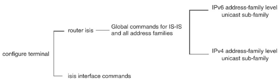
flowchart
graph TD
A["configure terminal"] --> B["router isis"]
A --> C["isis interface commands"]
B --> D["Global commands for IS-IS and all address families"]
C --> E["IPv6 address-family level unicast sub-family"]
C --> F["IPv4 address-family level unicast sub-family"]
The IS-IS CLI levels are as follows:
- A global level for the configuration of the IS-IS protocol. At this level, all IS-IS configurations at this level apply to IPv4 and IPv6. You enter this layer using the router isis command.
- Under the global level, you specify an address family. Address families to separate the IS-IS configurations for IPv4 and IPv6. You enter configurations that are for a specific You enter this level by entering the address-family command at the router isis level.
- Under the address family level, you select a sub-address family, which is the type of routes for the configuration. For IS-IS, you specify unicast.
NOTE
IS-IS IPv6 is currently not supported.
- An interface level.
Global configuration level
You enter the global configuration level of ISIS by entering the following command.
BigIron RX(config)#router isis BigIron RX(config-isis-router)#
Syntax: [no] router isis
The (config-isis-router) # prompt indicates that you are at the global level for IS-IS. Configurations you enter at this level apply to both IS-IS IPv4 and IS-IS IPv6.
Address family configuration level
The BigIron RX implementation of IS-IS includes the address family configuration level. Address families allow you to configure IPv4 IS-IS unicast settings that are separate and distinct from IPv6 IS-IS unicast settings, when IPv6 is supported.
Under the address family level, Brocade currently supports the unicast address family configuration level only. The device enters the IPv4 IS-IS unicast address family configuration level when you enter the following command while at the global IS-IS configuration level.
BigIron RX(config-isis-router)# address-family ipv4 unicast BigIron RX(config-isis-router-ipv4u)#
Syntax: address-family ipv4 unicast
The (config-isis-router-ipv4u) # prompt indicates that you are at the IPv4 IS-IS unicast address family configuration level. While at this level, you can access several commands that allow you to configure IPv4 IS-IS unicast settings.
NOTE
Each address family configuration level allows you to access commands that apply to that particular address family only. To enable a feature in a particular address family, you must specify any associated commands for that feature in that particular address family. You cannot expect the feature, which you may have configured in the IPv4 IS-IS unicast address family, to work in the IPv6 IS-IS unicast address family unless it is explicitly configured in the IPv6 IS-IS unicast address family.
To exit from the ipv4 IS-IS unicast address family configuration level, enter the following command.
BigIron RX(config-isis-router-ipv4u)# exit-address-family BigIron RX(config-isis-router)#
Entering this command returns you to the global IS-IS configuration level.
Interface level
Some IS-IS definitions are entered at the interface level. To enable IS-IS at the interface level, enter the following command.
BigIron RX(config)# interface ethernet 2/3 BigIron RX(config-if-e1000-2/3)#ip router isis
Syntax: [no] ip router isis
Configuring IPv4 IS-IS
Enabling IS-IS globally
To configure IPv4 IS-IS, do the following.
- Globally enable IS-IS by entering the following command.
BigIron RX(config)# router isis
ISIS: Please configure NET!
Once you enter router isis, the device enters the IS-IS router configuration level.
Syntax: [no] router isis
To disable IS-IS, use the no form of this command.
- If you have not already configured a NET for IS-IS, enter commands such as the following.
BigIron RX(config-isis-router)# net 49.2211.aaaa.bbbb.cccc.00
BigIron RX(config-isis-router)#
The commands in the example above configure a NET that has the area ID 49.2211, the system ID aaaa.bbbb.cccc (the device's base MAC address), and SEL value 00.
Syntax: [no] net
The
The
You must use the same system ID in all the NETs on the BigIron RX
NOTE
The parameter descriptions above are the recommended values for the NET. However, the CLI accepts any value that fits within the following lengths and formats.
xx.xxxx.xxxx.xxxx.00 - minimum length of NET
xx.xxxx.xxxx.xxxx.xxxx.xxxx.xxxx.xxxx.xxxx.xxxx.00 - maximum length of NET
The
To delete a NET, use the no form of this command.
- Configure ISIS parameters. Refer to "Globally configuring IS-IS on a device" on page 874, "Configuring IPv4 address family route parameters" on page 880, and "Configuring ISIS properties on an interface" on page 886.
None of the IS-IS parameters require a software reload to places changes into effect and most parameter changes take effect immediately. However, changes for the following parameters take effect only after you disable and then re-enable redistribution:
- Change the default metric.
- Add, change, or negate route redistribution parameters.
Some IS-IS parameter changes take effect immediately while others do not take full effect until you disable, then re-enable route redistribution.
Globally configuring IS-IS on a device
This section describes how to change the global IS-IS parameters. These parameter settings apply to both IS-IS IPv4 and IS-IS IPv6, although IPv6 is currently not supported.
Setting the overload bit
If an IS's resources are overloaded and are preventing the IS from properly performing IS-IS routing, the IS can inform other ISs of this condition by setting the overload bit in LSPDUs sent to other ISs from 0 (off) to 1 (on).
When an IS is overloaded, other ISs will not use the overloaded IS to forward traffic. An IS can be in the overload state for Level-1, Level-2, or both.
- If an IS is in the overload state for Level-1, other Level-1 ISs stop using the overloaded IS to forward Level-1 traffic. However, the IS can still forward Level-2 traffic, if applicable.
- If an IS is in the overload state for Level-2, other Level-2 ISs stop using the overloaded IS to forward Level-2 traffic. However, the IS can still forward Level-1 traffic, if applicable.
- If an IS is in the overload state for both levels, the IS cannot forward traffic at either level.
By default, the device automatically sets the overload bit to 1 (on) in its LSPDUs to other ISs if an overload condition occurs.
You can set the overload bit on to administratively shut down IS-IS without disabling the protocol. Setting the overload bit on is useful when you want to make configuration changes without removing the device from the network.
In addition, you can configure the device to set the overload bit on for a specific number of seconds during startup, to allow IS-IS to become fully active before the device begins IS-IS routing. By default, there is no delay (0 seconds).
To immediately set the overload bit on, enter the following command.
BigIron RX(config-isis-router)# set-overload-bit
This command administratively shuts down IS-IS by configuring the device to immediately set the overload bit to 1 (on) in all LSPs sent to other ISs.
To configure the device to temporarily set the overload bit on after a software reload, enter a command such as the following.
BigIron RX(config-isis-router)# set-overload-bit on-startup 5
This command configures the device to set the overload bit on in all its IS-IS LSPs sent to other ISs during the first five seconds following a successful software reload. After the five seconds expire, the device resets the overload bit to off in all its IS-IS LSPs.
Syntax: [no] set-overload-bit [on-startup
The on-startup
Configuring authentication
By default, the BigIron RX does not authenticate packets sent to or received from ESs or other ISs. You can configure the following types of passwords for IS-IS globally.
TABLE 134 IS-IS passwords
| Password type Scope Where used Default | ||
| Domain Level-2 Level-2 LSPDU None configured | ||
| Area Level-1 Level-1 LSPDU None configured | ||
| Interface Level-1 and Level-2 | Hello PDU | None configured |
If you configure a password, the device checks for the password in IS-IS packets received by the device and includes the password in packets sent by the device. For example, the device checks all Level-2 LSPDUs received by the device for the domain password you configure, and includes the password in all Level-2 PDUs sent by the device.
Configuring a domain password
To configure an IS-IS domain password, enter a command such as the following.
BigIron RX(config-isis-router)# domain-password domain-1
This command configures the device to use the password "domain-1" to authenticate Level-2 LSPDUs.
Syntax: [no] domain-password
The
Configuring an area password
To configure an IS-IS area password, enter a command such as the following.
BigIron RX(config-isis-router)# area-password area-51
This command configures the device to use the password "area-51" to authenticate Level-1 LSPDUs.
Syntax: [no] area-password
The
Changing the IS-IS Level globally
By default, a BigIron RX can operate as both a Level-1 and IS-IS Level-2 router. To globally change the level supported from Level-1 and Level-2 to Level-1 only, enter the following command.
BigIron RX(config-isis-router)# is-type level-1
Syntax: [no] is-type level-1 | level-1-2 | level-2
The level-1 | level-1-2 | level-2 parameter specifies the IS-IS type. If you want to re-enable support for both IS-IS types, re-enter the command you entered to change the IS-IS type, and use "no" in front of the command.
To change the IS-IS on an interface, refer to "Changing the IS-IS level on an interface" on page 888.
Disabling or re-enabling display of hostname
Brocade's implementation of IS-IS supports RFC 2763, which describes a mechanism for mapping IS-IS system IDs to the hostnames of the devices with those IDs. For example, if you set the hostname on the device to "IS-IS Router 1", the mapping feature uses this name instead of the device's IS-IS system ID in the output of the following commands.
• show isis database
• show isis interface
• show isis neighbor
The device's hostname is displayed in each CLI command prompt, for example.
BigIron RX(config-isis-router)#
The name mapping feature is enabled by default. If you want to disable name mapping, enter the following command.
BigIron RX(config-isis-router)# no hostname.
Syntax: [no] hostname
To display the name mappings, enter the show isis hostname command.
Changing the sequence numbers PDU interval
A Complete Sequence Numbers PDU (CSNP) is a complete list of the LSPs in the Designated IS' link state database. The CSNP contains a list of all the LSPs in the database, as well as other information that helps IS neighbors determine whether their LSP databases are in sync with one another. The Designated IS sends CSNPs to the broadcast interface. Level-1 and Level-2 each have their own Designated IS.
A Partial Sequence Numbers PDU (PSNP) is a partial list of LSPs. ISs other than the Designated IS (that is, the non-Designated ISs) send PSNPs to the broadcast interface.
The CSNP interval specifies how often the Designated IS sends a CSNP to the broadcast interface. Likewise, the PSNP interval specifies how often other ISs (non-Designated ISs) send a PSNP to the broadcast interface.
The interval you can configure on the device applies to both Level-1 and Level-2 CSNPs and PSNPs. The default interval is 10 seconds. You can set the interval to a value from 0 - 65535 seconds.
To change the interval, enter a command such as the following.
BigIron RX(config-isis-router)# csnp-interval 15
Syntax: [no] csnp-interval
The
NOTE
Although the command name is csnp-interval, the interval also applies to PSNPs.
Changing the maximum LSP lifetime
The maximum LSP lifetime is the maximum number of seconds an un-refreshed LSP can remain in the device's LSP database. The maximum LSP lifetime can be from 1 - 65535 seconds. The default is 1200 seconds (20 minutes).
To change the maximum LSP lifetime to 2400 seconds, enter a command such as the following.
BigIron RX(config-isis-router)# max-lsp-lifetime 2400
Syntax: [no] max-lsp-lifetime
The
NOTE
The max-lsp-lifetime and the lsp-refresh-interval must be set in such a way that the LSPs are refreshed before the max-lsp-lifetime expires; otherwise, the device's originated LSPs may be timed out by it's neighbors. Refer to “Changing the LSP refresh interval” on page 877.
Changing the LSP refresh interval
The LSP refresh interval is the maximum number of seconds the device waits between sending updated LSPs to its IS-IS neighbors. The interval can be from 1 - 65535 seconds. The default is 900 seconds.
To change the LSP refresh interval to 20000 seconds, enter a command such as the following.
BigIron RX(config-isis-router)# lsp-refresh-interval 20000
Syntax: [no] lsp-refresh-interval
The
Changing the LSP generation interval
The LSP generation interval is the minimum number of seconds the device waits between sending updated LSPs to its IS-IS neighbors. The interval can be from 1 - 120 seconds. The default is 10 seconds.
To change the LSP generation interval to 45 seconds, enter a command such as the following.
BigIron RX(config-isis-router)# lsp-gen-interval 45
Syntax: [no] lsp-gen-interval
The
Changing the LSP interval and retransmit interval
You LSP interval is the rate of transmission, in milliseconds of the LSPs. The retransmit interval is the time the device waits before it retransmits LSPs. To define an LSP interval, enter a command such as the following.
BigIron RX(config-isis-router)# lsp-interval 45
Syntax: [no] lsp-interval
Enter 1 - 4294967295 milliseconds for the LSP interval. The default is 33 milliseconds.
To define an interval for retransmission of LSPs enter a command such as the following.
BigIron RX(config-isis-router)# etransmit-interval 3
Syntax: [no] retransmit-interval
Enter 0 - 65535 seconds for the retransmission interval. The default is 5 seconds.
Changing the SPF timer
Every IS maintains a Shortest Path First (SPF) tree, which is a representation of the states of each of the IS's links to ESs and other ISs. If the IS is both a Level-1 and Level-2 IS, it maintains separate SPF trees for each level.
To ensure that the SPF tree remains current, the IS updates the tree at regular intervals following a change in network topology or the link state database. By default, the device recalculates its IS-IS tree every five seconds following a change. You can change the SPF timer to a value from 1 - 120 seconds.
To change the SPF interval, enter a command such as the following.
BigIron RX(config-isis-router)# spf-interval 30
Syntax: [no] spf-interval
The
Globally disabling or re-enabling hello padding
By default, the device adds extra data to the end of a hello packet to make the packet the same size as the maximum length of PDU the device supports.
The padding applies to the following types of hello packets:
- ES hello (ESH PDU)
- IS hello (ISH PDU)
- IS to IS hello (IIH PDU)
The padding consists of arbitrarily valued octets. A padded hello PDU indicates the largest PDU that the device can receive. Other ISs that receive a padded hello PDU from the device can therefore ensure that the IS-IS PDUs they send the device. Similarly, if the device receives a padded hello PDU from a neighbor IS, the device knows the maximum size PDU that the device can send to the neighbor.
When padding is enabled, the maximum length of a Hello PDU sent by the device is 1514 bytes.
If you need to disable padding, you can do so globally or on individual interfaces. Generally, you do not need to disable padding unless a link is experiencing slow performance. If you enable or disable padding on an interface, the interface setting overrides the global setting.
To globally disable padding of IS-IS hello PDUs, enter the following command.
BigIron RX(config-isis-router)# no hello padding
This command disables all hello PDU padding on the device. To re-enable padding, enter the following command.
BigIron RX(config-isis-router)# hello padding
Syntax: [no] hello padding
By default, hello padding is enabled. Enter the no form of the command to disable hello padding.
To disable hello padding on an interface, refer to “Disabling and enabling hello padding on an interface” on page 888.
Logging adjacency changes
The device can generate a Syslog entry and an SNMP trap to indicate a change in the status of an adjacency with another IS. Logging of the adjacency changes is disabled by default. To enable or disable them, use either of the following methods.
To enable logging of adjacency changes, enter the following command.
BigIron RX(config-isis-router)# log-adjacency-changes
Syntax: [no] log-adjacency-changes
To disable logging of adjacency changes, enter the following command.
BigIron RX(config-isis-router)# no log-adjacency-changes
Disabling partial SPF calculations
By default, IS-IS makes incremental changes to the routing table when changes to the network occur. A full SPF calculation is not performed unless there is a substantial change in the network; for example when an IS-IS link flaps in the network. You can optionally configure IS-IS to perform a full SPF calculation when any changes occur in the network.
To disable partial SPF calculations for IS-IS, enter the following command.
BigIron RX(config-isis-router)# disable-partial-spf-opt
Syntax: [no] disable-partial-spf-opt
Configuring IPv4 address family route parameters
This section describes how to modify the IS-IS parameters for the IS-IS IPv4 unicast address family. To enter the IPv4 unicast address family, refer to "Address family configuration level" on page 872.
Changing the metric style
The metric style specifies the Types, Lengths, and Values (TLVs) an IS-IS LSP can have. The TLVs specify the types of data, the maximum length of the data, and the valid values for the data. One of the types of data the TLVs control is a route's default-metric. By default, the device uses the standard IS-IS TLVs, which allows metric values from 1 – 63. The default metric style is called "narrow". You can increase the range of metric values supported by the device by changing the metric style to wide. The wide metric style allows metric values from 1 – 16777215.
To change the metric style to wide, enter the following command.
BigIron RX(config-isis-router-ipv4)# metric-style wide
This command changes the metric style for both Level-1 and Level-2.
Syntax: [no] metric-style wide [level-1 | level-2]
The level-1 | level-2 parameter specifies the levels to which the change applies. If not specified, the changes are applied to both levels.
Changing the maximum number of load sharing paths
By default, IPv4 IS-IS can calculate and install four equal-cost paths into the IPv4 forwarding table. You can change the number of paths IPv4 IS-IS can calculate and install in the IPv4 forwarding table to a value from
1 - 8. If you change the number of paths to one, the device does not load share multiple route paths learned from IPv4 IS-IS.
For example, to change the number of paths IPv4 IS-IS can calculate and install in the IPv4 forwarding table to three, enter the following command at the IPv4 IS-IS unicast address family configuration level.
BigIron RX(config-isis-router-ipv4u)# maximum-paths 4
Syntax: [no] maximum-paths
The
To return to the default number of maximum paths, enter the no form of this command.
Enabling advertisement of a default route
By default, the device does not generate or advertise a default route to its neighboring ISs. A default route is not advertised even if the device's IPv4 route table contains a default route. You can enable the device to advertise a default route to all neighboring ISs using one of the following methods. By default, the feature originates the default route at Level 2 only. However, you can apply a route map to originate the default route to Level 1 only or at both Level 1 and Level 2.
NOTE
This feature requires the presence of a default route in the IPv4 route table.
To enable the device to advertise a default route that is originated a Level 2, enter the following command at the IPv4 IS-IS unicast address family configuration level.
BigIron RX(config-isis-router-ipv4u)# default-information-originate
This command enables the device to advertise a default route into the IPv4 IS-IS area to which the device is attached.
Syntax: [no] default-information-originate [route-map
The route-map
- Advertise to Level-1 ISs only.
- Advertise to Level-2 ISs only.
- Advertise to Level-1 and Level-2 ISs.
NOTE
The route map must be configured before you can use the route map as a parameter with the default-information-originate command.
To use a route map to specify the router to advertise a default route to Level 1, enter commands such as the following at the Global CONFIG level.
BigIron RX(config)# route-map default_level1 permit 1
BigIron RX(config-routemap default_level1)# set level level-1
BigIron RX(config-routemap default_level1)# exit
BigIron RX(config)# router isis
BigIron RX(config-isis-router)# address-family ipv4 unicast
BigIron RX(config-isis-router-ipv4u)# default-information originate route-map default_level1
These commands configure a route map to set the default advertisement level to Level 1 only.
Syntax: [no] route-map
Syntax: [no] set level level-1 | level-1-2 | level-2
For this use of a route map, use the permit option and do not specify a match statement. Specify a set statement to set the level to one of the following:
• level-1 - Level 1 only.
• level-1-2 - Level 1 and Level 2.
• level-2 - Level 2 only (default).
Changing the administrative distance for IPv4 IS-IS
When the device has paths from multiple routing protocols to the same destination, it compares the administrative distances of the paths and selects the path with the lowest administrative distance to place in the IPv4 route table.
For example, if the router has a path from RIP, from OSPF, and IPv4 IS-IS to the same destination, and all the paths are using their protocols' default administrative distances, the router selects the OSPF path, because that path has a lower administrative distance than the RIP and IPv4 IS-IS paths.
Here are the default IPv4 administrative distances on the device:
- Directly connected - 0 (this value is not configurable)
- Static - 1 (applies to all static routes, including default routes)
- EBGP - 20
- OSPF - 110
- IPv4 IS-IS - 115
- RIP - 120
- IBGP - 200
- Local BGP - 200
- Unknown - 255 (the device will not use this route)
Lower administrative distances are preferred over higher distances. For example, if the device receives routes for the same network from IPv4 IS-IS and from RIP, it will prefer the IPv4 IS-IS route by default.
To change the administrative distance for IPv4 IS-IS routes, enter the following command at the IPv4 IS-IS unicast address family configuration level.
BigIron RX(config-isis-router-ipv4u)# distance 100
Syntax: [no] distance
This command changes the administrative distance for all IPv4 IS-IS routes to 100.
The
Configuring summary addresses
You can configure summary addresses to aggregate IS-IS route information. Summary addresses can enhance performance by reducing the size of the Link State database, reducing the amount of data the device needs to send to its neighbors, and reducing the CPU cycles used for IS-IS.
When you configure a summary address, the address applies only to Level-2 routes by default. You can specify Level-1 only, Level-2 only, or Level-1 and Level-2 when you configure the address.
To configure a summary address, enter a command such as the following.
BigIron RX(config-isis-router-ipv4u)# summary-address 192.168.0.0 255.255.0.0
This command configures a summary address for all Level-2 IS-IS route destinations between 192.168.1.0 - 192.168.255.255.
Syntax: [no] summary-address
The
The level-1 | level-1-2 | level-2 parameter specifies the route types to which the aggregate route applies. The default is level-2.
Redistributing routes into IPv4 IS-IS
To redistribute routes into IPv4 IS-IS, you can perform the following configuration tasks:
- Change the default redistribution metric (optional).
- Configure the redistribution of a particular route type into IPv4 IS-IS (mandatory).
The device can redistribute routes from the following route sources into IPv4 IS-IS:
- BGP4+.
- RIP.
- OSPF.
- Static IPv4 routes.
- IPv4 routes learned from directly connected networks.
The device can also can redistribute Level-1 IPv4 IS-IS routes into Level-2 IPv4 IS-IS routes, and Level-2 IPv4 IS-IS routes into Level-1 IPv4 IS-IS routes.
Route redistribution from other sources into IPv4 IS-IS is disabled by default. When you enable redistribution, the device redistributes routes only into Level 2 by default. You can specify Level 1 only, Level 2 only, or Level 1 and Level 2 when you enable redistribution.
The device automatically redistributes Level-1 routes into Level-2 routes. Thus, you do not need to enable this type of redistribution. You also can enable redistribution of Level-2 routes into Level-1 routes.
The device attempts to use the redistributed route's metric as the route's IPv4 IS-IS metric. For example, if an OSPF route has an OSPF cost of 20, the router uses 20 as the route's IPv4 IS-IS metric. The device uses the redistributed route's metric as the IPv4 IS-IS metric unless the route does not have a valid metric. In this case, the device assigns the default metric value to the route. For information about the default metric, refer to “Changing the default redistribution metric” on page 883, which follows this section.
Changing the default redistribution metric
When IPv4 IS-IS redistributes a route from another route source (such as OSPF, BGP4+, or a static IPv4 route) into IPv4 IS-IS, it uses the route's metric value as its metric when the metric is not modified by a route map or metric parameter and the default redistribution metric is set to its default value of 0. You can change the default metric to a value from 0 - 65535.
NOTE
The Brocade implementation of IS-IS does not support the optional metric types Delay, Expense, or Error.
For example, to change the default metric to 20, enter the following command at the IPv4 IS-IS unicast address family configuration level.
BigIron RX(config-isis-router-ipv4u)# default-metric 20
Syntax: [no] default-metric
The
To restore the default value for the default metric, enter the no form of this command.
Redistributing static IPv4 routes into IPv4 IS-IS
To redistribute static IPv4 routes from the IPv4 static route table into IPv4 IS-IS routes, enter the following command at the IPv4 IS-IS unicast address family configuration level.
BigIron RX(config-isis-router-ipv4u)# redistribute static
This command configures the device to redistribute all static IPv4 routes into Level-2 IS-IS routes.
Syntax: [no] redistribute static [level-1 | level-1-2 | level-2]
metric
The level-1, level-1-2, and level-2 keywords restrict redistribution to the specified IPv4 IS-IS level.
The metric
The metric-type external | internal parameter restricts redistribution to one of the following:
- external – The metric value is not comparable to an IPv4 IS-IS internal metric and is always higher than the IPv4 IS-IS internal metric.
- internal – The metric value is comparable to metric values used by IPv4 IS-IS. This is the default.
The route-map
BigIron RX(config)# access-list 101 permit ip any 192.168.0.0 255.255.0.0
BigIron RX(config)# route-map static permit 1
BigIron RX(config-routemap static)# match ip address 101
BigIron RX(config-routemap static)# router isis
BigIron RX(config-isis-router)# address-family ipv4 unicast
BigIron RX(config-isis-router-ipv4u)# redistribute static route-map static
Redistributing directly connected routes into IPv4 IS-IS
To redistribute directly connected IPv4 routes into IPv4 IS-IS routes, enter the following command at the IPv4 IS-IS unicast address family configuration level.
BigIron RX(config-isis-router-ipv4u)# redistribute connected
This command configures the device to redistribute all directly connected routes in the IPv4 route table into Level-2 IPv4 IS-IS.
Syntax: [no] redistribute connected [level-1 | level-1-2 | level-2]
metric
The parameters are the same as the parameters for the redistribute static command.
Redistributing RIP routes into IPv4 IS-IS
To redistribute RIP routes into IPv4 IS-IS, enter the following command at the IPv4 IS-IS unicast address family configuration level.
BigIron RX(config-isis-router-ipv4u)# redistribute rip
This command configures the device to redistribute all RIP routes into Level-2 IS-IS.
Syntax: [no] redistribute rip [level-1 | level-1-2 | level-2] | metric
The parameters are the same as the parameters for the redistribute static command.
Redistributing OSPF routes into IPv4 IS-IS
To redistribute OSPF routes into IPv4 IS-IS, enter the following command at the IPv4 IS-IS unicast address family configuration level.
BigIron RX(config-isis-router-ipv4u)# redistribute ospf
This command configures the device to redistribute all OSPF routes into Level-2 IPv4 IS-IS.
Syntax: [no] redistribute ospf [level-1 | level-1-2 | level-2] |
match [external1 | external2 | internal] |
metric
Most of the parameters are the same as the parameters for the redistribute static command. However, the redistribute ospf command also has the match external1 | external2 | internal parameter. This parameter specifies the OSPF route type you want to redistribute into IPv4 IS-IS. By default, the redistribute ospf command redistributes only internal routes.
- external1 - An OSPF type 1 external route.
- external2 - An OSPF type 2 external route.
- internal – An internal route calculated by OSPF.
Redistributing BGP4+ routes into IPv4 IS-IS
To redistribute BGP4+ routes into IPv4 IS-IS, enter the following command at the IPv4 IS-IS unicast address family configuration level.
BigIron RX(config-isis-router-ipv4u)# redistribute bgp
This command configures the router to redistribute all its BGP4 routes into Level-2 IPv4 IS-IS.
Syntax: [no] redistribute bgp [level-1 | level-1-2 | level-2] | metric
The parameters are the same as the parameters for the redistribute static command.
Redistributing IPv4 IS-IS routes within IPv4 IS-IS
In addition to redistributing routes from other route sources into IPv4 IS-IS, the BigIron RX can redistribute Level 1 IPv4 IS-IS routes into Level 2 IPv4 IS-IS routes, and Level 2 IPv4 IS-IS routes into Level 1 IPv4 IS-IS routes. By default, the device redistributes routes from Level 1 into Level 2.
NOTE
The BigIron RX automatically redistributes Level 1 routes into Level 2 routes, even if you do not enable redistribution.
For example, to redistribute all IPv4 IS-IS routes from Level 2 into Level 1, enter the following command at the IPv4 IS-IS unicast address family configuration level.
BigIron RX(config-isis-router-ipv4u)# redistribute isis level-2 into level-1
The router automatically redistributes Level-1 routes into Level 2.
Syntax: [no] redistribute isis level-1 into level-2 | level-2 into level-1 [prefix-list
The level-1 into level-2 | level-2 into level-1 parameter specifies the direction of the redistribution:
- level-1 into level-2 – Redistributes Level 1 routes into Level 2. This is the default.
• level-2 into level-1 – Redistributes Level 2 routes into Level 1.
The prefix-list
Configuring ISIS properties on an interface
This section describe the IS-IS parameters for an interface.
Disabling and enabling IS-IS on an interface
In addition to enabling IS-IS globally, you also must enable the protocol on the individual interfaces connected to ISs or ESs. To enable IS-IS locally on specific interfaces, enter commands such as the following.
BigIron RX(config)# interface ethernet 1/1
BigIron RX(config-if-1/1)# ip router isis
BigIron RX(config-if-1/1)# exit
BigIron RX(config)# interface ethernet 1/2
BigIron RX(config-if-1/2)# ip router isis
These commands enable IS-IS on ports 1/1 and 1/2. The NET configured above (at the IS-IS configuration level) applies to both interfaces.
Syntax: [no] ip router isis
Disabling or re-enabling formation of adjacencies
When you enable IS-IS on any type of interface except a loopback interface, the interface also is enabled to send advertisements and form an adjacency with an IS at the other end of the link by default. Adjacency formation and advertisements are disabled by default on loopback interfaces.
You can enable or disable adjacency formation and advertisements on an interface.
NOTE
The BigIron RX advertises an IS-IS interface to its area regardless of whether adjacency formation is enabled.
To disable IS-IS adjacency formation on an interface, enter commands such as the following.
BigIron RX(config)# interface ethernet 2/8 BigIron RX(config-if-e1000-2/8)# isis passive
This command disables IS-IS adjacency formation on port 2/8. The device still advertises this IS-IS interface into the area, but does not allow the port to form an adjacency with the IS at the other end of the link.
Syntax: [no] isis passive
Setting the priority for designated IS election
The priority of an IS-IS interface determines the priority of the interface for being elected as a Designated IS. Level-1 has a Designated IS and Level-2 has a Designated IS. The Level-1 and Level-2 Designated ISs are independent, although the same device can become both the Level-1 Designated IS and the Level-2 Designated IS.
By default, the Level-1 and Level-2 priority is 64. You can configure an interface's priority to a value from 0 - 127. You can configure the same priority for both Level-1 and Level-2 or you can configure a different priority for each level. In case of a tie (if two or more devices have the highest priority within a given level), the device with the highest MAC address becomes the Designated IS for that level.
NOTE
You can set the IS-IS priority on an individual interface basis only. You cannot set the priority globally.
To set the IS-IS priority on an interface, enter commands such as the following.
BigIron RX(config)# interface ethernet 2/8 BigIron RX(config-if-e1000-2/8)# isis priority 127
This command sets the IS-IS priority on port 1/1 to 127. Since the command does not specify Level-1 or Level-2, the new priority setting applies to both IS-IS levels.
Syntax: [no] isis priority
The
The level-1 | level-2 parameter applies the priority to Level-1 only or Level-2 only. By default, the priority is applied to both levels.
Limiting access to adjacencies with a neighbor
In addition to limiting access to an area (level-1) or domain (level-2), you can limit access to forming an IS-IS adjacency on a specific interface by entering a password at the interface configuration level. To enter this password, enter a command such as the following.
BigIron RX(config)# interface ethernet 2/8 BigIron RX(config-if-e1000-2/8)# isis password my-password
Syntax: [no] isis password
The
Changing the IS-IS level on an interface
The section “Changing the IS-IS Level globally” on page 876 explains how to change the IS-IS level globally. By default, a BigIron RX can operate as both a Level-1 and IS-IS Level-2 router. You can change the IS-IS type on an individual interface to be Level-1 only or Level-2 only. You also can reset the type to both Level-1 and Level-2.
NOTE
If you change the IS-IS type on an individual interface, the type you specify must also be specified globally. For example, if you globally set the type to Level-2 only, you cannot set the type on an individual interface to Level-1. The software accepts the setting but the setting does not take effect.
To change the IS-IS type on a specific interface, enter commands such as the following.
BigIron RX(config)# interface ethernet 2/8 BigIron RX(config-if-e1000-2/8)# isis circuit-type level-1
Syntax: [no] isis circuit-type level-1 | level-1-2 | level-2
The level-1 | level-1-2 | level-2 parameter specifies the IS-IS type. If you want to re-enable support for both IS-IS types, re-enter the command you entered to change the IS-IS type, and use "no" in front of the command.
Disabling and enabling hello padding on an interface
The section “Globally disabling or re-enabling hello padding” on page 878 explains what hello padding is, why it is important and how to globally disable or enable it on a device. You can also disable hello padding on a specific interface by entering commands such as the following.
BigIron RX(config)# interface ethernet 2/8 BigIron RX(config-if-e1000-2/8)# no isis hello padding
Syntax: [no] isis hello padding
By default, hello padding is enabled. Enter the no form of the command to disable hello padding.
Changing the hello interval
The hello interval controls how often an IS-IS interface sends hello messages to its IS-IS neighbors. The default interval is 10 seconds for Level-1 and Level-2. You can change the hello interval for one or both levels to a value from 1 - 65535 seconds.
To change the hello interval for Ethernet interface 2/8, enter commands such as the following.
BigIron RX(config)# interface ethernet 2/8 BigIron RX(config-if-e1000-2/8)# isis hello-interval 20
This command changes the hello interval to 20 seconds. By default, the change applies to both Level-1 and Level-2.
Syntax: [no] isis hello-interval
The
The level-1 | level-2 parameter applies the change to only the level you specify. If you do not use this parameter, the change applies to both levels.
Changing the hello multiplier
The hello multiplier is the number by which an IS-IS interface multiplies the hello interval to obtain the hold time for Level-1 and Level-2 IS-to-IS hello PDUs. The default multiplier is 3. You can set the multiplier to a value from
3 - 1000.
To change the hello multiplier for Ethernet interface 2/8, enter commands such as the following.
BigIron RX(config)# interface ethernet 2/8
BigIron RX(config-if-e1000-2/8)# isis hello-multiplier 50
This command changes the hello interval to 50. By default, the change applies to both Level-1 and Level-2.
Syntax: [no] isis hello-multiplier
The
The level-1 | level-2 parameter applies the change to only the level you specify. If you do not use this parameter, the change applies to both levels.
Changing the metric added to advertised routes
When the device originates an IS-IS route or calculates a route, the device adds a metric (cost) to the route. Each IS-IS interface has a separate metric value. The default is 10.
The device applies the interface-level metric to routes originated on the interface and also when calculating routes. The device does not apply the metric to link-state information that the device receives from one IS and floods to other ISs.
The default interface metric is 10. You can change the metric on an individual interface to a value in one of the following ranges:
- 1 – 63 for the narrow metric style (the default metric style for IPv4 ISIS)
• 1 - 16777215 for the wide metric style (the default metric style for IPv4 ISIS)
NOTE
If the metric value you want to use is higher than 63 but you have not changed the metric style to wide, change the metric style first, then set the metric. The IS-IS neighbors that will receive the advertisements also must be enabled to receive wide metrics.
To change the IS-IS metric on an interface, use the following CLI method.
BigIron RX(config)# interface ethernet 2/8
BigIron RX(config-if-e1000-2/8)# isis metric 15
Syntax: [no] isis metric
The
The level-1 | level-2 parameter applies the change to only the level you specify. If you do not use this parameter, the change applies to both levels.
Displaying IPv4 IS-IS information
You can display the following information:
- The active configuration (the IS-IS commands in the running-config) – refer to “Displaying the IS-IS configuration in the running-config” on page 890
- Name mappings – “Displaying the name mappings” on page 890
- Neighbor information – “Displaying neighbor information” on page 891
- Neighbor adjacency changes – “Displaying IS-IS Syslog messages” on page 892
- Interface information – “Displaying interface information” on page 893
- Route information – “Displaying route information” on page 896
- LSP database entries – “Displaying LSP database entries” on page 897
- Traffic statistics – “Displaying traffic statistics” on page 900
- Error statistics – “Displaying error statistics” on page 901
Displaying the IS-IS configuration in the running-config
You can display the global IS-IS configuration commands that are in effect on the device using the following CLI method.
NOTE
The running-config does not list the default values. Only commands that change a setting or add configuration information are displayed.
To list the global IS-IS configuration commands in the device's running-config, enter the following command at any level of the CLI.
BigIron RX# show isis config
router isis net 20.00e0.5200.0001.00 end
The running-config shown in this example contains the command that enables IS-IS and a command that configures a NET.
To display the interface configuration information in the running-config, enter one of the following commands at any level of the CLI.
• show running-config
- write terminal
Syntax: show isis config
Displaying the name mappings
To display the mappings, enter the following command at any level of the CLI.
BigIron RX# show isis hostname
Total number of entries in IS-IS Hostname Table: 1
System ID Hostname * = local IS
* bbbb.cccc.dddd RX
Syntax: show isis hostname
The table in this example contains one mapping, for this device. The device's IS-IS system ID is "bbbb.cccc.dddd" and its hostname is "RX". The display contains one entry for each IS that supports name mapping.
NOTE
Name mapping is enabled by default. When name mapping is enabled, the output of the show isis database, show isis interface, and show isis neighbor commands uses the host name instead of the system ID. To disable mapping so that these displays use the system ID instead, refer to “Disabling or re-enabling display of hostname” on page 876.
Displaying neighbor information
To display IS-IS neighbor information, enter the following command at any level of the CLI.
BigIron RX# show isis neighbor
Total number of IS-IS Neighbors: 2
System ID Interface SNPA State Holdtime Type Pri StateChgeTime
00e0.52b5.7800 Ether2/4 00e0.52b5.7843 UP 10 ISL2 64 0 :0 :16:8
00e0.52b5.7800 Ether2/4 00e0.52b5.7843 UP 10 ISL1 64 0 :0 :16:8
Syntax: show isis neighbor [detail]
The detail option displays more details for each neighbor.
This display shows the following information.
TABLE 135 IS-IS neighbor information
| This field... Displays... |
| Total number of IS-IS Neighbors The number of ISs with which the device has formed IS-IS adjacencies. |
| System ID The System ID of the neighbor or the hostname of the neighbor. |
| Interface The device port or virtual interface attached to the neighbor. |
| SNPA The Subnetwork Point of Attachment (SNPA), which is the MAC addressof the device port or virtual interface attached to the neighbor. |
| State The state of the adjacency with the neighbor. The state can be one ofthe following:DOWN - The adjacency is down.INIT - The adjacency is being established and is not up yet.UP - The adjacency is up. |
| Type The IS-IS type of the adjacency. The type can be one of the following:ISL1 – Level-1 ISISL2 – Level-2 ISES – ESNOTE:The device forms a separate adjacency for each IS-IS type. Thus, if the device has both types of IS-IS adjacencies with the neighbor, the display contains a separate row of information for each adjacency. |
| Pri The priority of this IS to be elected as the Designated IS in this broadcast network. |
| StateChgeTime The amount of time that has passed since the adjacency last changed state. |
Displaying IS-IS Syslog messages
When logging is enabled, the device generates Syslog messages and SNMP traps for the following IS-IS events:
• Overload state (the device entering or leaving the overload state)
• Memory overrun (IS-IS is demanding more memory than is available)
You also can enable the device to generate Syslog messages and SNMP traps when an adjacency with a neighbor comes up or goes down. To enable logging of adjacency changes, refer to “Logging adjacency changes” on page 879.
To display Syslog entries, enter the following command at any level of the CLI.
BigIron RX# show logging
Syslog logging: enabled (0 messages dropped, 0 flushes, 0 overruns)
Buffer logging: level ACDMEINW, 3 messages logged
level code: A=alert C=critical D=debugging M=emergency E=error
I=informational N=notification W=warning
Static Log Buffer:
Dynamic Log Buffer (50 lines):
00d00h00m42s:N:BGP Peer 192.147.202.10 UP (ESTABLISHED)
00d00h00m18s:N:ISIS L2 ADJACENCY UP 1234.1234.1234 on interface 2/8
00d00h00m08s:N:ISIS L1 ADJACENCY UP 1234.1234.1234 on interface 2/8
00d00h00m08s:N:ISIS L2 ADJACENCY UP 0000.86de.5520 on interface 5/1
00d00h00m00s:I:Warm start
The messages in this example indicate that the software has been reloaded (Warm start) and adjacencies between the device and three ISs have come up.
Syntax: show logging
Table 136 lists the IS-IS Syslog messages.
TABLE 136 IS-IS Syslog messages
| Message level Message Explanation | ||
| Alert ISIS MEMORY USE EXCEEDED IS-IS is requesting more memory than is available. | ||
| Notification | ISIS L1 ADJACENCY DOWNon interface | The device's adjacency with this Level-1 IS has gone down.Theis the system ID of the IS. Theis the ID of the interface over which the adjacency was established. |
| Notification | ISIS L1 ADJACENCY UPon interface | The device's adjacency with this Level-1 IS has come up.Theis the system ID of the IS. Theis the ID of the interface over which the adjacency was established. |
| Notification | ISIS L2 ADJACENCY DOWNon interface | The device's adjacency with this Level-2 IS has gone down.Theis the system ID of the IS. Theis the ID of the interface over which the adjacency was established. |
| Notification | ISIS L2 ADJACENCY UPon interface | The device's adjacency with this Level-2 IS has come up.Theis the system ID of the IS. Theis the ID of the interface over which the adjacency was established. |
| Notification ISIS ENTERED INTO OVERLOAD STATE The device has set the overload bit to (1), indicating that the device's IS-IS resources are overloaded. | ||
| Notification ISIS EXITED FROM OVERLOAD STATE The device has set the overload bit to off (0), indicating that the device's IS-IS resources are no longer overloaded. | ||
Displaying interface information
To display information about the device's IS-IS interfaces, enter the following command at any level of the CLI.
BigIron RX# show isis interface
Total number of IS-IS Interfaces: 1
Interface: Eth 7/1
Circuit State: UP Circuit Mode: LEVEL-1-2
Circuit Type: BCAST Passive State: FALSE
Circuit Number: 0x01, MTU: 1497
Authentication password: None
Level-1 Metric: 10, Level-1 Priority: 64
Level-1 Hello Interval: 10 Level-1 Hello Multiplier: 3
Level-1 Designated IS: RX-01 Level-1 DIS Changes: 8
Level-2 Metric: 10, Level-2 Priority: 64
Level-2 Hello Interval: 10 Level-2 Hello Multiplier: 3
Level-2 Designated IS: RX-01 Level-2 DIS Changes: 8
Next IS-IS LAN Level-1 Hello in 9 seconds
Next IS-IS LAN Level-2 Hello in 5 seconds
Number of active Level-1 adjacencies: 1
Number of active Level-2 adjacencies: 1
Circuit State Changes: 1 Circuit Adjacencies State Changes: 6
Rejected Adjacencies: 0
Circuit Authentication Fails: 0 Bad LSPs: 0
Control Messages Sent: 602 Control Messages Received: 2212
IP Enabled: TRUE
IP Address and Subnet Mask:
4.1.1.2 255.255.255.0
Syntax: show isis interface [brief | ethernet
This display shows the following information.
TABLE 137 IS-IS Interface information
| This field... Displays... |
| Total number of IS-IS interfaces The number of interfaces on which IS-IS is enabled. |
| Interface The port or virtual interface number to which the information listed below applies. |
| Local Circuit Number The ID that the instance of IS-IS running on the interface applied to the circuit between this interface and the interface at the other end of the link. |
| Circuit Type The type of IS-IS circuit running on the interface. The circuit type is set to BCAST (broadcast). |
| Circuit Mode The IS-IS type in use on the circuit. The mode can be one of the following:LEVEL-1LEVEL-2LEVEL-1-2 |
Circuit State The state of the circuit, which can be one of the following:
- DOWN
• UP
TABLE 137 IS-IS Interface information (Continued)
| This field... | Displays... |
| Passive State The passive state determines whether the interface is allowed to form an IS-IS adjacency with the IS at the other end of the circuit. The state can be one of the following:FALSE - The passive option is disabled. The interface can form an adjacency with the IS at the other end of the link.TRUE - The passive option is enabled. The interface cannot form an adjacency, but can still advertise itself into the area. | |
| MTU The maximum length supported for IS-IS PDUs sent on this interface. | |
| Authentication Password The password assigned to the IS-IS interface. | |
| Level-1 Metric The default-metric value that the device inserts in IS-IS Level-1 PDUs for this interface. | |
| Level-1 Priority The priority of this IS to be elected as the Designated IS for Level-1 in this broadcast network. | |
| Level-1 Hello Interval The number of seconds the software waits between sending Level-1 hello PDUs to the IS at the other end of the circuit. | |
| Level-1 Hello Multiplier The number by which the software multiplies the hello interval to calculate the hold time set in Level-1 Hello PDUs sent on the circuit. | |
| Level-1 Designated IS The NET of the Level-1 Designated IS. | |
| Level-1 DIS Changes The number of times the NET of the Level-1 Designated IS has changed. | |
| Level-2 Metric The default-metric value that the device inserts in IS-IS Level-2 PDUs for this interface. | |
| Level-2 Priority The priority of this IS to be elected as the Designated IS for Level-2 in this broadcast network. | |
| Level-2 Hello Interval The number of seconds the software waits between sending Level-2 Hello messages to the IS at the other end of the circuit. | |
| Level-2 Hello Multiplier The number by which the software multiplies the hello interval to calculate the hold time set for Level-2 Hello PDUs sent on this circuit. | |
| Level-2 Designated IS The NET of the Level-2 Designated IS. | |
| Level-2 DIS Changes The number of times the NET of the Level-2 Designated IS has changed. | |
| Next IS-IS LAN Level-1 Hello Number of seconds before next Level-1 Hello PDU will be transmitted by the device. | |
| Next IS-IS LAN Level-2 Hello Number of seconds before next Level-2 Hello PDU will be transmitted by the device. | |
| Number of active Level-1 adjacencies The number of ISs with which this interface has an active Level-1 adjacency. | |
| Number of active Level-2 adjacencies The number of ISs with which this interface has an active Level-2 adjacency. | |
| Circuit State Changes | The number of times the state of the circuit has changed. |
| Circuit State Adjacencies Changes | The number of times an adjacency has started or ended on this circuit. |
| Rejected Adjacencies | The number of adjacency attempts by other ISs rejected by the device. |
| Circuit Authentication Fails | The number of times the device rejected a circuit because the authentication did not match the authentication configured on the device. |
TABLE 137 IS-IS Interface information (Continued)
| This field... Displays... |
| Bad LSP The number of times the interface received a bad LSP from an IS at the other end of the circuit. The following conditions can cause an LSP to be bad:Invalid checksumInvalid lengthInvalid lifetime value |
| Control Messages Sent The number of IS-IS control PDUs sent on this interface. |
| Control Messages Received The number of IS-IS control PDUs received on this interface. |
| IP Enabled If set to TRUE, the IP protocol is enabled for this circuit. |
Displaying route information
To display the routes in the device's IS-IS route table, use either of the following methods.
To display information about the routes in the device's IS-IS route table, enter the following command at any level of the CLI.
| BigIron RX# show isis routesTotal number of IS-IS routes: 173 | |||||
| Destination | Mask | Cost | Type | Tag | Flags |
| 1.0.0.0 | 255.255.255.0 | 21 | L2 | 00000000 | 00000242 |
| Path: 1 | Next Hop IP: 4.1.1.1 | Interface: 7/1 | |||
| 1.0.0.0 | 255.255.255.255 | 30 | L2 | 00000000 | 00000242 |
| Path: 1 | Next Hop IP: 4.1.1.1 | Interface: 7/1 | |||
| 1.0.0.1 | 255.255.255.255 | 30 | L2 | 00000000 | 00000242 |
| Path: 1 | Next Hop IP: 4.1.1.1 | Interface: 7/1 | |||
| 1.0.10.0 | 255.255.255.0 | 30 | L2 | 00000000 | 00000242 |
| Path: 1 | Next Hop IP: 4.1.1.1 | Interface: 7/1 | |||
Syntax: show isis routes [ip-address
You may enter ip-address
For example:
| BigIron RX# show isis routes 1.0.111.0 255.255.255.0 | |||
| 1.0.111.0 | 255.255.255.0 | 21 | L2 00000000 00000242 |
| Path: 1 | Next Hop IP: 4.1.1.1 | Interface: 7/1 | |
This display shows the following information.
TABLE 138 IS-IS route information
| This field... Displays... |
| Total number of IS-IS routes The total number of routes in the device's IS-IS route table. The total includes Level-1 and Level-2 routes. |
| Destination The IP destination of the route. |
Mask The subnet mask for the destination address.
TABLE 138 IS-IS route information (Continued)
| This field... Displays... |
| Cost The IS-IS default metric for the route, which is the cost of using this routeto reach the next-hop router to this destination. |
| Type The route type, which can be one of the following:• L1 - Level-1 route• L2 - Level-2 route |
| Tag The tag value associated with the route. |
| Path The path number in the table. The IS-IS route table can contain multipleequal-cost paths to the same destination, in which case the paths arenumbered consecutively. When IP load sharing is enabled, the devicecan load balance traffic to the destination across the multiple paths. |
| Next Hop IP The IP address of the next-hop interface to the destination. |
| Interface The device interface (port or virtual interface) attached to the next hop. |
| Flags Values used by Brocade technical support for troubleshooting. |
Displaying LSP database entries
Use the following methods to display summary or detailed information about the entries in the LSP database.
NOTE
The BigIron RX maintains separate LSP databases for Level-1 LSPs and Level-2 LSPs.
Displaying summary information
To display summary information for all the LSPs in the device's LSP databases, enter the following command at any level of the CLI.
BigIron RX)# show isis database
| IS-IS Level-1 Link State Database | ||||
| LSPID | LSP Seq Num | LSP Checksum | LSP Holdtime | ATT/P/OL |
| RX-1.00-00 | 0x0000000c | 0xd048 | 963 | 1/0/0 |
| RX-1.01-00 | 0x00000004 | 0x09b0 | 957 | 0/0/0 |
| RX-1.02-00 | 0x00000001 | 0xc57b | 961 | 0/0/0 |
| RX.00-00* | 0x0000000b | 0x23fb | 1030 | 1/0/0 |
IS-IS Level-2 Link State Database
| LSPID | LSP Seq Num | LSP Checksum | LSP Holdtime | ATT/P/OL |
| RX-1.00-00 | 0x0000000d | 0x7d97 | 964 | 1/0/0 |
| RX-1.01-00 | 0x00000004 | 0x09b0 | 958 | 0/0/0 |
| RX-1.02-00 | 0x00000001 | 0x200f | 962 | 0/0/0 |
| RX.00-00* | 0x0000000b | 0x5647 | 1030 | 1/0/0 |
| 0000.0100.0003.00-00 | 0x0000001f | 0x761a | 932 | 0/0/0 |
| 0000.0100.0003.00-01 | 0x0000001d | 0x9c9d | 606 | 0/0/0 |
The command in this example shows information for the LSPS in the device's Level-1 and Level-2 LSP databases. Notice that the display groups the Level-1 and Level-2 LSPs separately.
Syntax: show isis database [
The
The detail parameter displays detailed information about the LSPs. Refer to “Displaying detailed information” on page 898.
The I1 and level1 parameters display the Level-1 LSPs only. You can use either parameter.
The I2 and level2 parameters display the Level-2 LSPs only. You can use either parameter.
The show isis database summary display shows the following information.
TABLE 139 IS-IS summary LSP database information
| This field... Displays... | |
| LSPID The LSP ID, which consists of the source ID (6 bytes), the pseudonode (1 byte), and LSPID (1 byte).NOTE: If the address has an asterisk (*) at the end, this indicates that the LSP is locally originated. | |
| LSP Seq Num The sequence number of the LSP. | |
| LSP Checksum The checksum calculated by the device that sent the LSP and used by the device to verify that the LSP was not corrupted during transmission over the network. | |
| LSP Holdtime The maximum number of seconds during which the LSP will remain valid.NOTE: The IS that originates the LSP sets the timer for the LSP. As a result, LSPs do not all have the same amount of time remaining when they enter the device's LSP database. | |
| ATT A 4-bit value extracted from bits 4 - 7 in the Attach field of the LSP. | |
| P The value in the Partition option field of the LSP. The field can have one of the following values:0 - The IS that sent the LSP does not support partition repair.1 - The IS that sent the LSP supports partition repair. | |
| OL | The value in the LSP database overload field of the LSP. The field can have one of the following values:0 - The overload bit is off.1 - The overload bit is on, indicating that the IS that sent the LSP is overloaded and should not be used as a IS-IS transit router for that level. |
Displaying detailed information
To display detailed information for all the LSPs in the device's LSP databases, enter the following command at any level of the CLI.
BigIron RX# show isis database detail
IS-IS Level-1 Link State Database
LSPID LSP Seq Num LSP Checksum LSP Holdtime ATT/P/OL
RX.00-00* 0x0000000b 0x23fb 971 1/0/0
Area Address: 49
NLPID: CC(IP)
Hostname: RX
Metric: 10 IP-Internal 4.1.1.0/24 Up-bit: 0
Metric: 10 IS RX.01
IS-IS Level-2 Link State Database
LSPID LSP Seq Num LSP Checksum LSP Holdtime ATT/P/OL
RX.00-00* 0x0000000d 0x7d97 903 1/0/0
Area Address: 49
NLPID: CC(IP)
Hostname: RX
IP address: 4.1.1.1
Metric: 10 IP-Internal 4.1.1.0/24 Up-bit: 0
Metric: 10 IP-Internal 192.85.1.0/24 Up-bit: 0
Metric: 10 IS RX.01
Metric: 10 IS RX.02
TABLE 140 IS-IS detailed LSP database information
| This field... Displays... |
| LSPID See the description of the summary display. |
| LSP Seq Num See the description of the summary display. |
| LSP Checksum See the description of the summary display. |
| LSP Holdtime See the description of the summary display. |
| ATT/P/OL See the description of the summary display. |
| Area Address The address of the area. |
NLPID The Network Layer Protocol Identifier (NLPID), which specifies the
protocol the IS that sent the LSP is using. Usually, this value is "CC(IP)".
TABLE 140 IS-IS detailed LSP database information (Continued)
| This field... Displays... | |
| IP address The IP address of the interface that sent the LSP. The device can usethis address as the next hop in routes to the addresses listed in the rows below. | |
| Destination addresses The rows of information below the IP address row are the destinationsadvertised by the LSP. The device can reach these destinations by using the IP address listed above as the next hop.Each destination entry contains the following information:Metric - The value of the default metric, which is the IS-IS cost of using the IP address above as the next hop to reach this destination.Device type - The device type at the destination. The type can be one of the following:End System - The device is an ES.IP-Internal - The device is an ES within the current area. The IP address and subnet mask are listed.IS - The device is another IS. The NET (NSAP address) is listed.IP-Extended - Same as IP-Internal, except the device uses the extended TLV fields described in draft-ietf-isis-traffic-02.txt to carry the information.IS-Extended - Same as IS, except the device uses the extended TLV fields described in draft-ietf-isis-traffic-02.txt to carry the information. |
Displaying traffic statistics
The device maintains statistics for common IS-IS PDU types. To display the statistics, use either of the following methods.
To display IS-IS PDU statistics, enter the following command at any level of the CLI.
| BigIron RX# show isis traffic | ||
| Message Received | Message Sent | |
| Level-1 Hellos | 1029 | 115 |
| Level-2 Hellos | 1027 | 112 |
| Level-1 LSP | 6 | 3 |
| Level-2 LSP | 6 | 3 |
| Level-1 CSNP | 0 | 0 |
| Level-2 CSNP | 0 | 0 |
| Level-1 PSNP | 107 | 0 |
| Level-2 PSNP | 107 | 0 |
Syntax: show isis traffic
This display shows the following information.
TABLE 141 IS-IS traffic statistics
| This field... Displays... |
| Level-1 Hellos The number of Level-1 hello PDUs sent and received by the device. |
| Level-2 Hellos The number of Level-2 hello PDUs sent and received by the device. |
| Level-1 LSP The number of Level-1 link-state PDUs sent and received by the device. |
| Level-2 LSP The number of Level-2 link-state PDUs sent and received by the device. |
| Level-1 CSNP The number of Level-1 Complete Sequence Number PDUs (CSNPs) sent and received by the device. |
| Level-2 CSNP The number of Level-2 CSNPs sent and received by the device. |
| Level-1 PSNP The number of Level-1 Partial Sequence Number PDUs (PSNPs) sent and received by the device. |
| Level-2 PSNP The number of Level-2 PSNPs sent and received by the device. |
Displaying error statistics
To display IS-IS error statistics, enter the following command at any level of the CLI.
BigIron RX# show isis counts
Area Mismatch: 0
Max Area Mismatch: 0
System ID Length Mismatch: 0
Authentication Fail: 0
Corrupted LSP: 0
LSP Sequence Number Skipped: 0
LSP Max Sequence Number Exceeded: 0
Level-1 Database Overload: 0
Level-2 Database Overload: 0
Our LSP Purged: 0
Syntax: show isis counts
This display shows the following information.
TABLE 142 IS-IS error statistics
| This field... Displays... | |
| Area Mismatch The number of times the device interface was unable to create a Level-1 adjacency with a neighbor because the device interface and the neighbor did not have any areas in common. | |
| Max Area Mismatch The number of times the device received a PDU whose value for maximum number of area addresses did not match the device's value for maximum number of area addresses. | |
| System ID Length Mismatch The number of times the device received a PDU whose ID field was a different length than the ID field length configured on the device. | |
| Authentication Fail | The device is configured to authenticate IS-IS packets in the packet's domain or area, but the packet did not contain the correct password. |
| Corrupted LSP | The number of times the device detected a corrupted LSP in the device's memory. |
TABLE 142 IS-IS error statistics (Continued)
| This field... Displays... |
| LSP Sequence Number Skipped The number of times the device received an LSP with a sequence number that was more than 1 higher than the sequence number of the previous LSP received from the same neighbor. |
| LSP Max Sequence Number Exceeded The number of times the device attempted to set an LSP sequence number to a value higher than the highest number in the CSNP sent by the Designated IS. |
| Level-1 Database Overload The number of times the Level-1 state on the device changed from Waiting to On or from On to Waiting.Waiting to On – This change can occur when the device recovers from a previous Level-1 LSP database overload and is again ready to receive new LSPs.On to Waiting – This change can occur when the device’s Level-1 LSP database is full and the device receives an additional LSP, for which there is no room. |
| Level-2 Database Overload The number of times the Level-2 state on the device changed from Waiting to On or from On to Waiting.The change from Waiting to On can occur when the device recovers from a previous Level-2 LSP database overload and is again ready to receive new LSPs.The change from On to Waiting can occur when the device’s Level-2 LSP database is full and the device receives an additional LSP, for which there is no room. |
| Our LSP Purged The number of times the device received an LSP that was originated by the device itself and had age zero (aged out). |
Clearing IS-IS information
To clear the IS-IS information that the device has accumulated since the last time you cleared information or reloaded the software, use either of the following methods.
To clear IS-IS information, enter a command such as the following at any level of the CLI except the User EXEC level.
BigIron RX# clear isis all
This command clears all the following.
- Neighbors (closes the BigIron RX's adjacencies with its IS-IS neighbors)
- Routes
- PDU statistics
- Error statistics
Syntax: clear isis all | counts | neighbor | route [
The all parameter clears all the IS-IS information. Using this option is equivalent to entering separate commands with each of the other options.
The counts parameter clears the error statistics.
The neighbor parameter closes the device's adjacencies with its IS-IS neighbors and clears the neighbor statistics.
The route [
The traffic parameter clears the PDU statistics.
NOTE
The traffic option also clears the values displayed in the show isis interface command's Control Messages Sent and Control Messages Received fields.
The BigIron RX provides support for Bidirectional Forwarding Detection (BFD), which defines a method of rapid detection of the failure of a forwarding path by checking that the next hop router is alive. Without BFD enabled, it can take from 3 to 30 seconds to detect that a neighboring router is not operational causing packet loss due to incorrect routing information at a level unacceptable for real-time applications such as VOIP and video over IP. Using BFD, you can detect a forwarding path failure in 300 milliseconds or less depending on your configuration.
A BFD session is automatically established when a neighbor is discovered for a protocol provided that BFD is enabled on the interface on which the neighbor is discovered and BFD is also enabled for the protocol (by interface or globally). Once a session is set-up, each router transmits control messages at a high rate of speed that is negotiated by the routers during the session setup. To provide a detection time of 150 milliseconds, it is necessary to process 20 messages per second of about 70 to 100 bytes each per each session. A similar number of messages also needs to be transmitted out per each session. Once a session is set-up, that same message is continuously transmitted at the negotiated rate and a check is made that the expected control message is received at the agreed frequency from the neighbor. If the agreed upon messages are not received from the neighbor within a short period of time, the neighbor is considered to be down. The maximum number of sessions supported on an interface module (LP) is 20 while the maximum per system is 100.
NOTE
BFD session establishment on an interface does not start until 90 seconds after the interface comes up. The reason for this delay is to ensure that the link is not effected by unstable link conditions which could cause BFD to flap. This delay time is not user configurable.
The BFD Control Message is an UDP message with destination port 3784.
NOTE
BFD version 0 is not supported in this implementation and BFD version 1 is not compatible with BFD version 0.
NOTE
BFD supports multi-slot trunks in cases where all BFD packet are transmitted only on a single path which does not change unless the trunk active membership changes. BFD is not be supported on multi-slot trunks where per-packet switching is used such that the path taken by the BFD packets will vary per packet.
Configuring BFD parameters
When you configure BFD you must set timing and interval parameters. These are configured on each interface. When two adjacent interfaces with BFD are configured, they negotiate the conditions for determining if the connection between them is still active. The following command is used to set the BFD parameters.
BigIron RX(config-if-e1000-3/1)# bfd interval 100 min-rx 100 multiplier 3
Syntax: [no] bfd interval
The
This value is specified in milliseconds.
Acceptable values are: 50 - 30000.
The
NOTE
The transit-time and receive-time variables set with this command are the intervals desired by the local router. The actual values in use will be the negotiated values.
The
Acceptable values are: 3 - 50.
Number of BFD sessions supported
The device supports a maximum of 100 BFD sessions per system with a maximum number of 20 sessions per interface module. This number is inclusive of the fact that IS-IS and OSPF sessions on an interface module will include both transmit and receive sessions. Consequently, the 20 sessions per interface module actually corresponds to 40 sessions where each OSPF and IS-IS session consumes two sessions (one transmit and one receive).
Disabling BFD Syslog messages
Syslog messages are generated for BFD operation. These messages are described in "Brocade Syslog messages". Logging of these messages is enabled by default. To disable logging of BFD messages use the following command.
BigIron RX(config)# no logging enable bfd
Syntax: [no] logging enable bfd
BFD logging is enabled by default. If you disable BFD logging as shown, you can re-enable it by using the logging enable bfd command.
Displaying Bidirectional Forwarding Detection information
You can display Bidirectional Forwarding Detection (BFD) information for the router you are logged-in to and for BFD configured neighbors as described in the following sections.
Displaying BFD information on a router
The following example illustrates the output from the show bfd command.
| BigIron RX# show bfd | ||||||
| BFD State: ENABLED Version: 1 | ||||||
| Current Registered Protocols: ospf ospf6 | ||||||
| All Sessions: Current: 2 Maximum Allowed: 100 Maximum Exceeded Count: 0 | ||||||
| LP Sessions: Maximum Allowed on LP: 20 Maximum Exceeded Count for LPs: 0 | ||||||
| LP Sessions | LP Sessions | LP Sessions | LP Sessions | LP Sessions | LP Sessions | |
| 1 | 0 | 2 | 2 | 3 | 0 | 4 |
| 5 | 0 | 6 | 0 | 7 | 0 | 8 |
| 9 | 0 | 10 | 0 | 11 | 0 | 12 |
| 13 | 0 | 14 | 0 | 15 | 0 | 16 |
| BFD Enabled ports count: 2 | ||||||
| Port | MinTx | MinRx | Mult Sessions | |||
| eth 2/1 | 100 | 100 | 3 | 2 | ||
Syntax: show bfd
This display shows the following information.
TABLE 143 Display of BFD information
| This field... Displays... | |
| BFD State Specifies if BFD is Enabled or Disabled on the router. | |
| Version Specifies the version of the BFD protocol operating on the router. | |
| Current Registered Protocols Specifies which protocols are registered to use BFD on the router.Possible values are ospf, ospf6, or isis_task | |
| All Sessions | |
| Current: The number of BFD sessions currently operating on the router. | |
| Maximum Allowed The maximum number of BFD sessions that are allowed on the router.The maximum number of sessions supported on a router is 100. | |
| Maximum Exceeded Count The number of times the request to set up a BFD session was declined because it would have resulted in exceeding the maximum number of BFD sessions allowed on the router. | |
| LP Sessions | |
| Maximum Allowed on LP | The maximum number of BFD sessions that are allowed on an interface module. The maximum number of sessions supported on an interface module is 20. |
| Maximum Exceeded Count for LPs The number of times the request to set up a BFD session was declined because it would have resulted in exceeding the maximum number of BFD sessions allowed on an Interface module. | |
| LP The number of the Interface module that the Current Session Count is displayed for. | |
| Sessions | The number of BFD sessions currently operating on the specified Interface module. |
| BFD Enabled ports count | The number of ports on the router that have been enabled for BFD. |
| Port | The port that BFD is enabled on. |
| MinTx | The interval in milliseconds between which the router desires to send a BFD message from this port to its peer. |
| MinRx | The interval in milliseconds that this router desires to receive a BFD message from its peer on this port. |
TABLE 143 Display of BFD information (Continued)
| This field... Displays... |
| Mult The number of times that the router will wait for the MinRx time on this port before it determines that its peer router is non-operational. |
| Sessions The number of BFD sessions originating on this port. |
Displaying BFD application information
The following example illustrates the output from the show bfd application command.
| Protocol | Parameter |
| ospf | 1 |
| ospf6 | 0 |
| isis_task | 0 |
This display shows the following information.
TABLE 144 Display of BFD application information
| This field... Displays... |
| Parameter The parameter value passed by the protocol during registration with BFD. |
Displaying BFD neighbor information
The following example illustrates the output from the show bfd neighbor command.
| BigIron RX# show bfd neighbor | |||||
| Total number of Neighbor entries: 2 | |||||
| NeighborAddress | State | Interface | Holddown | Interval | RH |
| 12.14.1.1 | UP | eth 3/1 | 300000 | 100000 | 1 |
| 12.2.1.1 | UP | eth 2/1 | 300000 | 100000 | 1 |
Syntax: show bfd neighbor [interface ethernet
The interface ethernet option displays BFD neighbor information for the specified ethernet interface only.
The interface ve option displays BFD neighbor information for the specified virtual interface only.
This display shows the following information.
TABLE 145 Display of BFD information
| This field... Displays... |
| Total number of Neighbor entries The number of neighbors that have established BFD sessions with ports on this router. |
| NeighborAddress The IPv4 or IPv6 address of the remote peer. |
State The current state of the BFD session.
Up - Up
Down - Down
A.DOWN - The administrative down state.
INIT - The Init state.
UNKNOWN - The current state is unknown.
TABLE 145 Display of BFD information (Continued)
| This field... Displays... |
| Interface The logical port (physical or virtual port) on which the peer is known. The physical port can be either Ethernet or POS. |
| Holddown The interval after which the session will transition to the down state if no message is received. |
| Interval The negotiated interval at which the local router sends BFD messages to the remote peer. |
| RH Heard from remote. |
To display BFD Neighbor information in the detailed format use the following command.
| NeighborAddress | State | Interface | Holddown | Interval | RH |
| 12.14.1.1 | UP | ve 50 | 300000 | 100000 | 1 |
| Registered Protocols: ospf | |||||
| Local: Disc: 1, Diag: 0, Demand: 0 Poll: 0 | |||||
| MinTxInterval: 100000, MinRxInterval: 100000, Multiplier: 3 | |||||
| Remote: Disc: 22, Diag: 7, Demand: 0 Poll: 0 | |||||
| MinTxInterval: 100000, MinRxInterval: 100000, Multiplier: 3 | |||||
| Stats: RX: 72089 TX: 72101 SessionUpCount: 1 at SysUpTime: 0:1:30:54.775 | |||||
| Session Uptime: 0:1:30:6.375, LastSessionDownTimestamp: 0:0:0:0.0 | |||||
| Physical Port: eth 4/1, Vlan Id: 50 | |||||
Syntax: show bfd neighbor details [IpAddress | IPv6Address]
This display shows the following information.
TABLE 146 Display of BFD neighbor detail information
| This field... Displays... | |
| Total number of Neighbor entries Total number of BFD sessions. | |
| NeighborAddress IPv4 or IPv6 address of the remote peer. | |
| State The current state of the BFD session. | |
| Up | |
| Down | |
| A.DOWN - The administrative down state. | |
| INIT - The Init state. | |
| UNKNOWN - The current state is unknown. | |
| Interface The logical port on which the peer is known. | |
| Holddown The interval after which the session will transition to the down state if no message is received. | |
| Interval The interval at which the local router sends BFD messages to the remote peer. | |
| RH | Heard from remote. |
| Registered Protocols | Specifies which protocols are registered to use BFD on this port. |
| Local | |
Disc
Value of the "local discriminator" field in the BFD Control Message as used by the local router in the last message sent.
TABLE 146 Display of BFD neighbor detail information (Continued)
| This field... | Displays... |
| Diag Value of the “diagnostic” field in the BFD Control Message as used by the local router in the last message sent. | |
| Demand Value of the “demand” bit in the BFD Control Message as used by the local router in the last message sent. | |
| Poll Value of the “poll” bit in the BFD Control Message as used by the local router in the last message sent. | |
| MinTxInterval The interval in microseconds between which the router negotiates to send a BFD message from this local neighbor port to its peer. | |
| MinRxInterval The interval in microseconds that the neighbor router waits to receive a BFD message from its peer on this local port. | |
| Multiplier The number of times that the neighbor router will wait for the MinRxInterval time on this port before it determines that its peer router is non-operational. | |
| Remote | |
| Disc Value of the “local discriminator” field in the BFD Control Message as received in the last message sent by the remote peer. | |
| Diag Value of the “diagnostic” field in the BFD Control Message as received in the last message sent by the remote peer. | |
| Demand Value of the “demand” bit in the BFD Control Message as received in the last message sent by the remote peer. | |
| Poll Value of the “poll” bit in the BFD Control Message as received in the last message sent by the remote peer. | |
| MinTxInterval The interval in microseconds between which the router negotiates to send a BFD message from the remote neighbor port to its peer. | |
| MinRxInterval The interval in microseconds that the neighbor router waits to receive a BFD message from its peer on this remote port. | |
| Multiplier The number of times that the remote neighbor router will wait for the MinRxInterval time on this port before it determines that its peer router is non-operational. | |
| Stats: Rx Total number of BFD control messages received from the remote peer. | |
| Stats: Tx Total number of BFD control messages sent to the remote peer. | |
| Stats: SessionUpCount The number of times the session has transitioned to the UP state. | |
| Stats: SysUpTime The amount of time that the system has been up. | |
| Session Uptime The amount of time the session has been in the UP state. | |
| LastSessionDownTimestamp | The system time at which the session last transitioned from the UP state to some other state. |
| Physical Port | The physical port on which the peer is known. |
| Vlan Id | The VLAN ID of the VLAN that the physical port is resident on. |
Clearing BFD neighbor sessions
You can clear all BFD neighbor sessions or a specified BFD neighbor session using the following command.
BigIron RX# clear bfd neighbor
Syntax: clear bfd neighbor [
The
The
Executing this command without specifying an IP or IPv6 address clears the sessions of all BFD neighbors.
Configuring BFD for the specified protocol
BFD can be configured for use with the following protocols:
- OSPFv2
- OSPFv3
• IS-IS
Configuring BFD for OSPFv2
You can configure your BigIron RX router for BFD on the OSPFv2 protocol for all OSPFv2 enabled interfaces or for specific interfaces as shown in the following sections.
Enabling BFD for OSPFv2 for all interfaces
You can configure BFD for OSPFv2 on all of a router's OSPFv2 enabled interfaces using the command shown in the following"
BigIron RX (config)# router ospf BigIron RX(config-ospf-router)# bfd all-interfaces
Syntax: [no] bfd all-interfaces
While this command configures BFD for OSPFv2 on all of a router's OSPFv2 enabled interfaces, it is not required that it be configured if you use the ip ospf bfd command to configure specific interfaces. It can be used independently or together with that command.
Enabling or disabling BFD for OSPFv2 for a specific interface
You can selectively enable or disable BFD on any OSPFv2 interface as shown in the following.
BigIron RX# (config-if-e1000-3/1)# ip ospf bfd
Syntax: ip ospf bfd [disable]
The disable option disables BFD for OSPFv2 on the interface.
Configuring BFD for OSPFv3
You can configure your BigIron RX router for BFD on the OSPFv3 protocol for all OSPFv3 enabled interfaces or for specific interfaces as shown in the following sections.
Enabling BFD for OSPFv3 for all interfaces
You can configure BFD for OSPFv3 on all of a router's OSPFv3 enabled interfaces using the command shown in the following.
BigIron RX(config)# ipv6 router ospf BigIron RX(config-ospf6-router)# bfd all-interfaces
Syntax: [no] bfd all-interfaces
While this command configures BFD for OSPFv3 on all of a router's OSPFv3 enabled interfaces, it is not required that it be configured if you use the ipv6 ospf bfd command to configure specific interfaces. It can be used independently or together with that command.
Enabling or disabling BFD for OSPFv3 for a specific interface
You can selectively enable or disable BFD on any OSPFv3 interface as shown in the following.
BigIron RX# (config-if-e1000-3/1)# ipv6 ospf bfd
Syntax: ipv6 ospf bfd [disable]
The disable option disables BFD for OSPFv3 on the interface.
Configuring BFD for IS-IS
You can configure your BigIron RX router for BFD for the IS-IS protocol for all IS-IS enabled interfaces or for specific interfaces as shown in the following sections.
Enabling BFD for IS-IS for all interfaces
You can configure IS-IS for IS-IS on all of a router's IS-IS enabled interfaces using the command shown in the following"
BigIron RX(config)# router isis BigIron RX(config-isis-router)# bfd all-interfaces
Syntax: [no] bfd all-interfaces
While this command configures BFD for IS-IS on all of a router's IS-IS enabled interfaces, it is not required that it be configured if you use the isis bfd command to configure specific interfaces. It can be used independently or together with that command.
Enabling or disabling BFD for IS-IS for a specific interface
You can selectively enable or disable BFD on any IS-IS interface as shown in the following.
BigIron RX# (config-if-e1000-3/1)# isis bfd
Syntax: isis bfd [disable]
The disable option disables BFD for IS-IS on the interface.
In this chapter
• Overview of Secure Shell (SSH) 913
- Configuring SSH. 914
- Displaying SSH connection information.... 921
- Using secure copy 922
Overview of Secure Shell (SSH)
Secure Shell (SSH) is a mechanism for allowing secure remote access to management functions on a BigIron RX. SSH provides a function similar to Telnet. Users can log into and configure the device using a publicly or commercially available SSH client program, just as they can with Telnet. However, unlike Telnet, which provides no security, SSH provides a secure, encrypted connection to the device.
SSHv2 is supported on the device. Brocade's SSHv2 implementation is compatible with all versions of the SSHv2 protocol (2.1, 2.2, and so on). At the beginning of an SSH session, the device negotiates the version of SSHv2 to be used. The highest version of SSHv2 supported by both the device and the client is the version that is used for the session. Once the SSHv2 version is negotiated, the encryption algorithm with the highest security ranking is selected to be used for the session.
Also, the device support Secure Copy (SCP) for securely transferring files between a device and an SCP-enabled remote hosts. Refer to "Using secure copy" on page 922 for more information.
NOTE
The SSH feature includes software that is copyright Allegro Software Development Corporation.
SSH version 2 support
SSHv2 is a substantial revision of Secure Shell, comprising the following hybrid protocols and definitions:
• SSH Transport Layer Protocol
• SSH Authentication Protocol
- SSH Connection Protocol
• SECSH Public Key File Format
- SSH Fingerprint Format
• SSH Protocol Assigned Numbers
- SSH Transport Layer Encryption Modes
- SCP/SFTP/SSH URI Format
If you are using redundant management modules, you can synchronize the DSA host key pair between the active and standby modules by entering the sync-standby command at the Privileged EXEC level of the CLI.
Tested SSHv2 clients
The following SSH clients have been tested with SSHv2:
- SSH Secure Shell 3.2.3
• Van Dyke SecureCRT 4.0 and 4.1
• F-Secure SSH Client 5.3 and 6.0
• PuTTY 0.54 and 0.56 - OpenSSH 3.5_p1 and 3.6.1p2
- Solaris Sun-SSH-1.0
Supported features
The SSH server allows secure remote access management functions on a device. SSH provides a function that is similar to Telnet, but unlike Telnet, SSH provides a secure, encrypted connection.
SSHv2 support includes the following:
- The following encryption cipher algorithm are supported. They are listed in order of preference:
- aes256-cbc: AES in CBC mode with 256-bit key
- aes192-cbc: AES in CBC mode with 192-bit key
- aes128-cbc: AES in CBC mode with 128-bit key
- 3des-cbc: Triple-DES
• Key exchange methods, in the order of preference are:
• diffie-hellman-group1-sha1
• diffie-hellman-group14-sha1
• Public key algorithm is ssh-dss.
• Data integrity is ensured with hmac-sha1 algorithm.
• Supported authentication methods are Password and publickey. - Compression is not supported.
- TCP/IP port forwarding, X11 forwarding, and secure file transfer are not supported.
- SSH version 1 is not supported.
- SCP supports AES encryption
Configuring SSH
Brocade's implementation of SSH supports two kinds of user authentication:
- DSA challenge-response authentication, where a collection of public keys are stored on the device. Only clients with a private key that corresponds to one of the stored public keys can gain access to the device using SSH.
- Password authentication, where users attempting to gain access to the device using an SSH client are authenticated with passwords stored on the device or on a TACACS, TACACS+ or RADIUS server
Both kinds of user authentication are enabled by default. You can configure the device to use one or both of them.
To configure Secure Shell on a device, do the following.
- Generate a host DSA public and private key pair for the device.
- Configure DSA challenge-response authentication.
- Set optional parameters.
You can also view information about active SSH connections on the device as well as terminate them.
Generating a host key pair
When SSH is configured, a public and private host DSA key pair is generated for the device. The SSH server on the device uses this host DSA key pair, along with a dynamically generated server DSA key pair, to negotiate a session key and encryption method with the client trying to connect to it.
The host DSA key pair is stored in the device's system-config file. Only the public key is readable. The public key should be added to a "known hosts" file (for example, \$HOME/.ssh/known_hosts on UNIX systems) on the clients who want to access the device. Some SSH client programs add the public key to the known hosts file automatically; in other cases, you must manually create a known hosts file and place the device's public key in it. Refer to "Providing the public key to clients" on page 916 for an example of what to place in the known hosts file.
While the SSH listener exists at all times, sessions can't be started from clients until a key is generated. Once a key is generated, clients can start sessions. The keys are also not displayed in the configuration file by default. To display the keys, use the ssh show-host-keys command in Privileged EXEC mode. To generate a public and private DSA host key pair on a device, enter the following commands.
BigIron RX(config)# crypto key generate
When a host key pair is generated, it is saved to the flash memory of all management modules.
To disable SSH in SSHv2 on a device, enter the following commands.
BigIron RX(config)# crypto key zeroize
When SSH is disabled, it is deleted from the flash memory of all management modules.
Syntax: crypto key generate | zeroize
The generate keyword places an DSA host key pair in the flash memory and enables SSH on the device.
The zeroize keyword deletes the DSA host key pair from the flash memory and disables SSH on the device.
By default, public keys are hidden in the running configuration. You can optionally configure the device to display the DSA host key pair in the running configuration file entering the following command.
BigIron RX# ssh show-host-keys
Syntax: ssh show-host-keys
To hide the public keys in the running configuration file, enter the following command.
BigIron RX# ssh no-show-host-keys
Syntax: ssh no-show-host-keys
Providing the public key to clients
If you are using SSH to connect to a device from a UNIX system, you may need to add the device's public key to a "known hosts" file; for example, \$HOME/.ssh/known_hosts. The following is an example of an entry in a known hosts file.
AAAAB3NzaC1kc3MAAACBAPY8ZOHY2yFSJA6XYC9HRwNHxaehvx5wOJ0rzZdzoSOXxbETW6ToHv8D1UJ/
z+zHo9Fiko5XybZnDIaBDHtblQ+Yp7StxyltHnXF1YLfKD1G4T6JYrdH YI14Om
1eg9e4NnCRleaqoZPF3UGfZia6bXrGTQf3gJq2e7Yisk/gF+1VAAAAFQDb8D5cv
wHWTZDPfX0D2s9Rd7NBvQAAAIEA1N92+Bb7D4KLYk3IwRbXblwXdkPggA4pfdtW9v
GfJ0/RHd+NjB4eo1D+0dix6tXwYGN7PKS5R/FXPNwxHPapcj9uL1Jn2AWQ2dsknf+i/FAA
vioUFkmdMc0zuWoSOEsSNhVDtX3WdvVcGcBq9cetzrtOKWOocJmJ80qadxTRHtUAAACB
AN7CY+KKv1gHpRzFwdQm7HK9bb1LAo2KwaoXnadFgeptNBQeSXG1vO+JsvphVMBJc9HS
n24VYtYtsMu74qXviYjziVucWKjjKEb11juqnF0GD1B3VVmxHLmxnAz643WK42Z7dLM5
sY29ouezv4Xz2PuMch5VGPP+CDqzCM4loWgV
Configuring DSA challenge-response authentication
With DSA challenge-response authentication, a collection of clients' public keys are stored on the device. Clients are authenticated using these stored public keys. Only clients that have a private key that corresponds to one of the stored public keys can gain access to the device using SSH.
When DSA challenge-response authentication is enabled, the following events occur when a client attempts to gain access to the device using SSH.
- The client sends its public key to the device.
- The device compares the client's public key to those stored in memory.
- If there is a match, the device uses the public key to encrypt a random sequence of bytes.
- The device sends these encrypted bytes to the client.
- The client uses its private key to decrypt the bytes.
- The client sends the decrypted bytes back to the device.
- The device compares the decrypted bytes to the original bytes it sent to the client. If the two sets of bytes match, it means that the client's private key corresponds to an authorized public key, and the client is authenticated.
Setting up DSA challenge-response authentication consists of the following steps.
- Importing authorized public keys into the device.
- Enabling DSA challenge response authentication
Importing authorized public keys into the device
SSH clients that support DSA authentication normally provide a utility to generate an DSA key pair. The private key is usually stored in a password-protected file on the local host; the public key is stored in another file and is not protected. You should collect one public key from each client to be granted access to the device and place all of these keys into one file. This public key file is imported into the device.
The following is an example of a public key file containing one public keys.
---- BEGIN SSH2 PUBLIC KEY ----
Comment: DSA Public Key
AAAAB3NzaC1kc3MAAACBAPY8ZOHY2yFSJA6XYC9HRwNHxaehvx5wOJ0rzZdzoSOXxbETW6ToHv8D1UJ/
z+zHo9Fiko5XybZnDIaBDHtblQ+Yp7StxyltHnXF1YLfKD1G4T6JYrdH YI14Om
leg9e4NnCRleaqoZPF3UGfZia6bXrGTQf3gJq2e7Yisk/gF+1VAAAAFQDb8D5cv
wHWTZDPfX0D2s9Rd7NBvQAAAIEA1N92+Bb7D4KLYk3IwRbXblwXdkPggA4pfdtW9v
GfJ0/RHd+NjB4eo1D+0dix6tXwYGN7PKS5R/FXPNwxHPapcj9uL1Jn2AWQ2dsknf+i/FAA
vioUPkmdMc0zuWoSOEsSNhVDtX3WdvVcGcBq9cetzrtOKWOocJmJ80qadxTRHtUAAACB
AN7CY+KKv1gHpRzFwdQm7HK9bb1LAo2KwaoXnadFgeptNBQeSXG1vO+JsvphVMBJc9HS
n24VYtYtsMu74qXviYjziVucWKjjKEb11juqnF0GD1B3VVmxHLmxnAz643WK4227dLM5
sY29ouezv4Xz2PuMch5VGPP+CDqzCM4loWgV
---- END SSH2 PUBLIC KEY ----
You can import the authorized public keys into the active configuration by loading them from a file on a TFTP server and are saved on the EEPROM of the device. If you import a public key file from a TFTP server, the file is automatically loaded into the active configuration the next time the device is booted.
NOTE
You must ensure the format is followed before the key is TFTPed to the Brocade device.
NOTE
The public key may not be effective after download using Linux and Secure CRT. If the file is not constructed properly, you will receive an error message while loading. You must fix the key files and load them again.
To cause a public key file called pkeys.txt to be loaded from a TFTP server each time the device is booted, enter a command such as the following.
BigIron RX(config)# ip ssh pub-key-file tftp 192.168.1.234 pkeys.txt
Syntax: ip ssh pub-key-file tftp |
The
The
The remove parameter deletes the key from the system.
To display the currently loaded public keys, enter the following command.
BigIron RX# show ip client-pub-key
---- BEGIN SSH2 PUBLIC KEY ----
Comment: DSA Public Key
AAAAB3NzaC1kc3MAAACBAPY8ZOHY2yFSJA6XYC9HRwNHxaehvx5wOJ0rzZdzoSOXxbETW6ToHv8D1UJ/
z+zHo9Fiko5XybZnDIaBDHtblQ+Yp7StxyltHnXF1YLfKD1G4T6JYrdH YI14Om
leg9e4NNcRleaqoZPF3UGfZia6bXrGTQf3gJq2e7Yisk/gF+1VAAAAFQDb8D5cv
wHWTZDPfX0D2s9Rd7NBvQAAAIEA1N92+Bb7D4KLYk3IwRbXblwXdKpggA4pfdtW9v
GfJ0/RHd+NjB4eo1D+0dix6tXwYGN7PKS5R/FXPNwxHPapcj9uL1Jn2AWQ2dsknf+i/FAA
vioUPkmdMc0zuWoSOEsSNhVDtX3WdvVcGcBq9cetzrtOKWOocJmJ80qadxTRHtUAAACB
AN7CY+KKv1gHpRzFwdQm7HK9bblLAo2KwaoXnadFgeptNBQeSXG1vO+JsvphVMBJc9HS
n24VYtYtsMu74qXviYjziVucWKjjKEb11juqnF0GD1B3VVmxHLmxnAz643WK42Z7dLM5
sY29ouezv4Xz2PuMch5VGPP+CDqzCM4loWgV
---- END SSH2 PUBLIC KEY ----
Syntax: show ip client-pub-key [ | begin
To clear the public keys from the buffers, enter the following command.
BigIron RX# clear public-key
Syntax: clear public-key
Use the ip ssh pub-key remove command to delete the public key from the system.
Enabling DSA challenge-response authentication
DSA challenge-response authentication is enabled by default. You can disable or re-enable it manually.
To enable DSA challenge-response authentication.
BigIron RX(config)# ip ssh key-authentication yes
To disable DSA challenge-response authentication.
BigIron RX(config)# ip ssh key-authentication no
Syntax: ip ssh key-authentication yes | no
Setting the number of SSH authentication retries
By default, the device attempts to negotiate a connection with the connecting host three times. The number of authentication retries can be changed to between 1 - 5.
For example, the following command changes the number of authentication retries to 5.
BigIron RX(config)# ip ssh authentication-retries 5
Syntax: ip ssh authentication-retries
Deactivating user authentication
After the SSH server on the device negotiates a session key and encryption method with the connecting client, user authentication takes place. Brocade's implementation of SSH supports DSA challenge-response authentication and password authentication.
With DSA challenge-response authentication, a collection of clients' public keys are stored on the device. Clients are authenticated using these stored public keys. Only clients that have a private key that corresponds to one of the stored public keys can gain access to the device using SSH.
With password authentication, users are prompted for a password when they attempt to log into the device (provided empty password logins are not allowed; refer to "Enabling empty password logins" on page 919). If there is no user account that matches the user name and password supplied by the user, the user is not granted access.
You can deactivate one or both user authentication methods for SSH. Note that deactivating both authentication methods essentially disables the SSH server entirely.
To disable DSA challenge-response authentication.
BigIron RX(config)# ip ssh key-authentication no
Syntax: ip ssh key-authentication yes | no
The default is "yes".
To deactivate password authentication.
BigIron RX(config)# ip ssh password-authentication no
Syntax: ip ssh password-authentication no | yes
The default is "yes".
Enabling empty password logins
By default, empty password logins are not allowed. This means that users with an SSH client are always prompted for a password when they log into the device. To gain access to the device, each user must have a user name and password. Without a user name and password, a user is not granted access. Refer to "Setting up local user accounts" on page 74 for information on setting up user names and passwords on the device.
If you enable empty password logins, users are not prompted for a password when they log in. Any user with an SSH client can log in without being prompted for a password.
To enable empty password logins.
BigIron RX(config)# ip ssh permit-empty-passwd yes
Syntax: ip ssh permit-empty-passwd no | yes
Setting the SSH port number
By default, SSH traffic occurs on TCP port 22. You can change this port number. For example, the following command changes the SSH port number to 2200.
BigIron RX(config)# ip ssh port 2200
Note that if you change the default SSH port number, you must configure SSH clients to connect to the new port. Also, you should be careful not to assign SSH to a port that is used by another service. If you change the SSH port number, Brocade recommends that you change it to a port number greater than 1024.
Syntax: ip ssh port
Setting the SSH login timeout value
When the SSH server attempts to negotiate a session key and encryption method with a connecting client, it waits a maximum of 120 seconds for a response from the client. If there is no response from the client after 120 seconds, the SSH server disconnects. You can change this timeout value to between 1 - 120 seconds. For example, to change the timeout value to 60 seconds.
BigIron RX(config)# ip ssh timeout 60
Syntax: ip ssh timeout
Designating an interface as the source for all SSH packets
You can designate a loopback interface, virtual interface, or Ethernet port as the source for all SSH packets from the device. The software uses the IP address with the numerically lowest value configured on the port or interface as the source IP address for SSH packets originated by the device.
NOTE
When you specify a single SSH source, you can use only that source address to establish SSH management sessions with the device.
To specify the numerically lowest IP address configured on a loopback interface as the device's source for all SSH packets, enter commands such as the following.
BigIron RX(config)# int loopback 2
BigIron RX(config-lbif-2)# ip address 10.0.0.2/24
BigIron RX(config-lbif-2)# exit
BigIron RX(config)# ip ssh source-interface loopback 2
The commands in this example configure loopback interface 2, assign IP address 10.0.0.2/24 to the interface, then designate the interface as the source for all SSH packets from the device.
Syntax: ip ssh source-interface ethernet
The
BigIron RX(config)# interface ethernet 1/4
BigIron RX(config-if-e10000-1/4)# ip address 209.157.22.110/24
BigIron RX(config-if-e10000-1/4)# exit
BigIron RX(config)# ip ssh source-interface ethernet 1/4
Configuring maximum idle time for SSH sessions
By default, SSH sessions do not time out. Optionally, you can set the amount of time an SSH session can be inactive before the device closes it. For example, to set the maximum idle time for SSH sessions to 30 minutes.
BigIron RX(config)# ip ssh idle-time 30
Syntax: ip ssh idle-time
If an established SSH session has no activity for the specified number of minutes, the device closes it. An idle time of 0 minutes (the default value) means that SSH sessions never time out. The maximum idle time for SSH sessions is 240 minutes.
Filtering SSH access using ACLs
You can permit or deny SSH access to the device using ACLs. To use ACLs, first create the ACLs you want to use. You can specify a numbered standard IPv4 ACL, a named standard IPv4 ACL.
Then enter the following command.
BigIron RX(config)# access-list 10 permit host 192.168.144.241
BigIron RX(config)# access-list 10 deny host 192.168.144.242 log
BigIron RX(config)# access-list 10 permit host 192.168.144.243
BigIron RX(config)# access-list 10 deny any
BigIron RX(config)# ssh access-group 10
Syntax: ssh access-group < standard-named-acl> | < standard-numbered-acl>
Refer to the section Chapter 21, "Access Control List" for details on how to configure ACLs.
Disabling 3-DES
By default, both 3-DES and AES encryption algorithms are enabled on the BigIron RX device. You can disable 3-DES by entering the following command.
BigIron RX(config)# ip ssh encryption aes-only
Syntax: [no] ip ssh encryption aes-only
Displaying SSH connection information
Up to five SSH connections can be active on the device. To display information about SSH connections, enter the following command.
BigIron RX# show ip ssh
Connection Version Encryption Username
1 SSH-2 3des-cbc Hanuma
2 SSH-2 aes128-cbc Mikaila
3 SSH-2 aes192-cbc Jenny
4 SSH-2 aes256-cbc Mariah
5 SSH-2 3des-cbc Logan
Syntax: show ip ssh [ | begin < expression> | exclude < expression> | include < expression>]
This display shows the following information about the active SSH connections.
TABLE 147 SSH connection information
| This field... Displays... |
| Connection The SSH connection ID. This can be from 1 - 5. |
| Version The SSH version number. This should always be 1.5. |
| Encryption The encryption method used for the connection. |
| Username The user name for the connection. |
The show who command also displays information about SSH connections. For example.
BigIron RX#show who
Console connections:
established, monitor enabled, in config mode
2 minutes 17 seconds in idle
Telnet connections (inbound):
1 closed
2 closed
3 closed
4 closed
5 closed
Telnet connection (outbound):
6 closed
SSH connections:
1 established, client ip address 192.168.144.241, user is hanuma
1 minutes 16 seconds in idle
2 established, client ip address 192.168.144.241, user is Mikaila
you are connecting to this session
18 seconds in idle
3 established, client ip address 192.168.144.241, user is Jenny
1 minutes 39 seconds in idle
4 established, client ip address 192.168.144.242, user is Mariah
41 seconds in idle
5 established, client ip address 192.168.144.241, user is Logan
23 seconds in idle
Syntax: show who [| begin
To terminate one of the active SSH connections, enter the following command.
BigIron RX# kill ssh 1
Syntax: kill ssh
Using secure copy
Secure Copy (SCP) uses security built into SSH to transfer files between hosts on a network, providing a more secure file transfer method than Remote Copy (RCP) or FTP. SCP automatically uses the authentication methods, encryption algorithm, and data compression level configured for SSH. For example, if password authentication is enabled for SSH, the user is prompted for a user name and password before SCP allows a file to be transferred. No additional configuration is required for SCP on top of SSH.
You can use SCP to copy files on the device, including the startup configuration and running configuration files, to or from an SCP-enabled remote host.
SCP is enabled by default and can be disabled. To disable SCP, enter the following command.
BigIron RX(config)# ip ssh scp disable
Syntax: ip ssh scp disable | enable
NOTE
If you disable SSH, SCP is also disabled.
The following are examples of using SCP to transfer files from and to a device.
NOTE
When using SCP, you enter the scp commands on the SCP-enabled client, rather than the console on the device.
NOTE
Certain SCP client options, including -p and -r, are ignored by the SCP server on the device. If an option is ignored, the client is notified.
To copy a configuration file (c:\cfg\brocade.cfg) to the running configuration file on a device at 192.168.1.50 and log in as user terry, enter the following command on the SCP-enabled client.
C:\> scp c:\cfg\brocade.cfg terry@192.168.1.50:runConfig
If password authentication is enabled for SSH, the user is prompted for user terry's password before the file transfer takes place.
To copy the configuration file to the startup configuration file.
C:\> scp c:\cfg\brocade.cfg terry@192.168.1.50:startConfig
To copy the configuration file to a file called config1.cfg on the PCMCIA flash card in slot 1 on a management module.
C:\> scp c:\cfg\brocade.cfg terry@192.168.1.50:slot1:/config1.cfg
To copy the configuration file to a file called config1.cfg on the PCMCIA flash card in slot 2 on a management module.
C:\> scp c:\cfg\brocade.cfg terry@192.168.1.50:slot2:/config1.cfg
To copy the running configuration file on a device to a file called c:\cfg\fdryrun.cfg on the SCP-enabled client.
C:\> scp terry@192.168.1.50:runConfig c:\cfg\fdryrun.cfg
To copy the startup configuration file on a device to a file called c:\cfg\fdrystart.cfg on the SCP-enabled client.
C:\> scp terry@192.168.1.50:startConfig c:\cfg\fdrystart.cfg
- Brocade Communications Systems, Incorporated
- Document History
- Contents
- About This Document
- Chapter 1 Getting Started with the Command Line Interface
- Chapter 2 Getting Familiar With the BigIron RX Series Switch Management Applications
- Chapter 3 Using a Redundant Management Module
- Chapter 4 Securing Access to Management Functions
- Chapter 5 Configuring Basic Parameters
- Chapter 6 Configuring Interface Parameters
- Chapter 7 Configuring IP
- Chapter 8 Link Aggregation
- Chapter 9 Configuring LLDP
- Chapter 10 Configuring Uni-Directional Link Detection (UDLD)
- Chapter 11 VLANs
- Chapter 12 Configuring Spanning Tree Protocol
- Chapter 13 Configuring Rapid Spanning Tree Protocol
- Chapter 14 Metro Ring Protocol (MRP) Phase 1 and 2
- Chapter 15 Virtual Switch Redundancy Protocol (VSRP)
- Chapter 16 Topology Groups
- Chapter 17 Configuring VRRP and VRRPE
- Chapter 18 Configuring Quality of Service
- Chapter 19 Configuring Traffic Reduction
- Chapter 20 Layer 2 ACLs
- Chapter 21 Access Control List
- Chapter 22 Policy-Based Routing
- Chapter 23 Configuring IP Multicast Protocols
- Chapter 24 Configuring RIP
- Chapter 25 Configuring OSPF Version 2 (IPv4)
- Chapter 26 Configuring BGP4 (IPv4 and IPv6)
- Chapter 27 Configuring MBGP
- Chapter 28 Configuring IS-IS (IPv4)
- Chapter 29 BiDirectional Forwarding Detection (BFD)
- Chapter 30 Configuring Secure Shell
- Chapter 31 Configuring Multi-Device Port Authentication
- Chapter 32 Using the MAC Port Security Feature and Transparent Port Flooding
- Chapter 33 Configuring 802.1x Port Security
- Chapter 34 Protecting Against Denial of Service Attacks
- Chapter 35 Inspecting and Tracking DHCP Packets
- Chapter 36 Securing SNMP Access
- Chapter 37 Enabling the Foundry Discovery Protocol (FDP) and Reading Cisco Discovery Protocol (CDP) Packets
- Chapter 38 Remote Network Monitoring
- Chapter 39 Configuring sFlow
- Chapter 40 Multiple Spanning Tree Protocol (MSTP) 802.1s
- Chapter 41 Configuring IP Multicast Traffic Reduction
- Chapter 42 IPv6 Addressing
- Chapter 43 Configuring Basic IPv6 Connectivity
- Chapter 44 Configuring RIPng
- Chapter 45 Configuring BGP4+
- Chapter 46 Configuring IPv6 MBGP
- Chapter 47 IPv6 Access Control Lists (ACLs)
- Chapter 48 Configuring OSPF Version 3
- Chapter 49 Configuring IPv6 Multicast Features
- Chapter 50 Configuring IPv6 Routes
- Chapter 51 Continuous System Monitor
- Appendix A Using Syslog
- Appendix B Software Specifications
- Appendix C NIAP-CCEVS Certification
- Appendix D Commands That Require a Reload
- Appendix E Index to the CLI Commands
- Audience
- Supported hardware and software
- List of supported features
- Unsupported features
- What's new in this document
- Enhancements in release 02.8.00
- Enhancements in release 02.7.03
- Enhancements in release 02.7.02
- Enhancements in release 02.7.01
- Enhancements in release 02.7.00
- Enhancements in release 02.6.00
- Enhancements in patch release 02.5.00c
- Enhancements in patch release 02.5.00b
- Enhancements in release 02.5.00
- Enhancements in patch release 02.4.00c
- Enhancements in release 02.4.00
- Enhancements in patch release 02.3.00a
- Enhancements in release 02.3.00
- System enhancements
- Layer 2 enhancements
- Layer 3 enhancements
- IP multicast enhancements
- IP service, security, and Layer 4 enhancements
- Network management
- Enhancements in release 02.2.01
- Hardware enhancements
- Multicast enhancement
- Security enhancements
- Enhancements in release 02.2.00g
- Enhancements in release 02.2.00
- Document conventions
- Text formatting
- Command syntax conventions
- Notes, cautions, and danger notices
- NOTE
- CAUTION
- DANGER
- Notice to the reader
- Related publications
- Getting technical help or reporting errors
- E-mail and telephone access
- In this chapter
- Logging on through the CLI
- On-line help
- Command completion
- Scroll control
- Line editing commands
- EXEC commands
- User level
- Privileged EXEC level
- Global level
- CONFIG commands
- Redundancy level
- Interface level
- Trunk level
- Router RIP level
- Router OSPF level
- BGP level
- Global BGP and BGP4 Unicast address family level
- BGP4 multicast address family level
- Router DVMRP level
- Router PIM level
- Route Map level
- Router VRRP level
- Router VRRPE level
- VLAN level
- Metro ring level
- VSRP level
- Topology group level
- 802.1x port security level
- MAC port security level
- Accessing the CLI
- Navigating among command levels
- CLI command structure
- Required or optional fields
- Optional fields
- List of available options
- Searching and filtering output
- Searching and filtering output from show commands
- Displaying lines that do not contain a specified string
- Displaying lines starting with a specified string
- Searching and filtering output at the --More-- prompt
- Using special characters in regular expressions
- Allowable characters for LAG names
- Syntax shortcuts
- Saving configuration changes
- Getting Familiar With the BigIron RX Series Switch Management Applications
- How to manage BigIron RX Series switch
- Searching and filtering output from CLI commands
- Displaying lines containing a specified string
- The filtered results are displayed:
- Logging on through the Web Management Interface
- Web Management Interface
- How management module redundancy works
- Management module redundancy overview
- Management module switchover
- Unavailable active module
- Manual switchover
- Removal and replacement of an active management module
- Removal and replacement of a standby management module
- Switchover implications
- Management sessions
- Syslog and SNMP traps
- MAC address changes
- Layer 2 Hitless Failover
- Management module redundancy configuration
- Changing the default active slot
- Managing management module redundancy
- File synchronization between the active and standby management modules
- Comparing and synchronizing files
- Synchronizing files without comparison
- Manually switching over to the standby management module
- Rebooting the active and standby management modules
- Monitoring management module redundancy
- Determining management module status
- Status LED
- Software
- Syntax: show module
- Displaying temperature information
- Syntax: show chassis
- Displaying switchover information
- Flash memory and PCMCIA flash card file management commands
- Management focus
- Flash memory file system
- File naming conventions
- PCMCIA flash card file system
- PCMCIA flash card subdirectories
- File and subdirectory naming conventions
- Wildcards
- Formatting a flash card
- Determining the current management focus
- Switching the management focus
- Displaying a directory of the files
- Displaying the contents of a file
- Displaying the hexadecimal output of a file
- Creating a subdirectory
- Removing a subdirectory
- Renaming a file
- Changing the read-write attribute of a file
- Deleting a file
- Recovering ("undeleting") a file
- Appending a file to another file
- Copying files using the copy command
- Copying files from one flash card to the other
- Copying files between a flash card and flash memory
- Copying software image from a flash card to the flash memory
- Copying software images between active and standby management modules
- Copying files from a management module to an interface module
- Copying BigIron RX Series Multi-Service IronWare images from flash memory to a TFTP server
- Copying files between a flash card and a TFTP server
- Copying the startup-config file between a flash card and flash memory
- Copying the startup-config file between flash memory and a TFTP server
- Copying the running-config to a flash card or a TFTP server
- Loading a running-config from a flash card or a TFTP server
- Copying files using the cp command
- Loading the software
- Rebooting from the system
- Configuring the boot source for future reboots
- Displaying the current location for saving configuration changes
- Specifying the location for saving configuration changes
- File management messages
- Securing access methods
- Restricting remote access to management functions
- Using ACLs to restrict remote access
- Using an ACL to restrict Telnet access
- Using an ACL to restrict SSH access
- Using an ACL to restrict Web management access
- Using ACLs to restrict SNMP access
- Configuring hardware-based remote access filtering on the device
- Restricting remote access to the device to specific IP addresses
- Restricting Telnet access to a specific IP address
- Restricting SSH access to a specific IP address
- Restricting Web Management access to a specific IP address
- Restricting SNMP access to a specific IP address
- Restricting all remote management access to a specific IP address
- Specifying the maximum number of login attempts for Telnet access
- Restricting remote access to the device to specific VLAN IDs
- Restricting Telnet access to a specific VLAN
- Restricting Web management access to a specific VLAN
- Restricting SNMP access to a specific VLAN
- Restricting TFTP access to a specific VLAN
- Disabling specific access methods
- Disabling Telnet access
- Disabling Web management access
- Disabling Web management access by HP ProCurve Manager
- Disabling SNMP access
- Setting passwords
- Setting a Telnet password
- Suppressing Telnet connection rejection messages
- Setting passwords for management privilege levels
- Augmenting management privilege levels
- Recovering from a lost password
- Displaying the SNMP community string
- Disabling password encryption
- Specifying a minimum password length
- Setting up local user accounts
- Configuring a local user account
- Changing local user passwords
- Using the CLI
- Using the Web Management Interface
- Username, password and login rules
- Configuring the strict password feature
- Requiring users to accept the message of the day
- Locking out user accounts after three login attempts
- Retaining password history
- Setting passwords to expire
- Creating an encrypted all-numeric password
- Granting access by time of day
- Configuring SSL security for the Web Management Interface
- Enabling the SSL server on the device
- Specifying a port for SSL communication
- Importing digital certificates and RSA private key files
- Generating an SSL certificate
- Deleting the SSL certificate
- Configuring TACACS and TACACS+ security
- How TACACS+ differs from TACACS
- TACACS and TACACS+ authentication, authorization, and accounting
- TACACS authentication
- TACACS+ authentication
- TACACS+ authorization
- TACACS+ accounting
- AAA operations for TACACS and TACACS+
- AAA security for commands pasted Into the running configuration
- TACACS and TACACS+ configuration considerations
- TACACS configuration procedure
- TACACS+ configuration procedure
- Enabling SNMP to configure TACACS and TACACS
- Identifying the TACACS and TACACS+ servers
- Specifying different servers for individual AAA functions
- Setting optional TACACS and TACACS+ parameters
- Setting the TACACS+ key
- Setting the retransmission limit
- Setting the dead time parameter
- Setting the timeout parameter
- Configuring authentication-method lists for TACACS and TACACS+
- Entering privileged EXEC mode after a Telnet or SSH login
- Configuring Enable authentication to prompt for password only
- Telnet/SSH prompts when the TACACS+ server is unavailable
- Configuring TACACS+ authorization
- Configuring Exec authorization
- Configuring an Attribute-Value pair on the TACACS+ server
- Configuring command authorization
- Configuring TACACS+ accounting
- Configuring TACACS+ accounting for Telnet/SSH (Shell) access
- Configuring TACACS+ accounting for CLI commands
- Configuring TACACS+ accounting for system events
- Configuring an interface as the source for all TACACS and TACACS+ packets
- Displaying TACACS and TACACS+ statistics and configuration information
- Syntax: show aaa
- Configuring RADIUS security
- RADIUS authentication, authorization, and accounting
- RADIUS authentication
- RADIUS authorization
- RADIUS accounting
- AAA operations for RADIUS
- RADIUS configuration considerations
- RADIUS configuration procedure
- Configuring Brocade-specific attributes on the RADIUS server
- Enabling SNMP to configure RADIUS
- Identifying the RADIUS server to the BigIron RX
- Setting RADIUS parameters
- Setting the RADIUS key
- Configuring authentication-method lists for RADIUS
- Configuring RADIUS authorization
- Command authorization and accounting for console commands
- Configuring RADIUS accounting
- Configuring RADIUS accounting for Telnet/SSH (Shell) access
- Configuring RADIUS accounting for CLI commands
- Configuring RADIUS accounting for system events
- Configuring an interface as the source for all RADIUS packets
- Displaying RADIUS configuration information
- Configuring authentication-method lists
- Configuration considerations for authentication-method lists
- Examples of authentication-method lists
- Entering system administration information
- Configuring Simple Network Management Protocol traps
- Specifying an SNMP trap receiver
- Specifying a Single trap source
- Setting the SNMP Trap holddown time
- Disabling SNMP traps
- Disabling Syslog messages and traps for CLI access
- Examples of Syslog messages for CLI access
- Syntax: show logging
- Disabling the Syslog messages and traps
- Configuring an interface as source for all Telnet packets
- Cancelling an outbound Telnet session
- Configuring an interface as the source for all TFTP packets
- Configuring an interface as the source for Syslog packets
- Specifying a Simple Network Time Protocol (SNTP) server
- Setting the system clock
- New Daylight Saving Time (DST)
- Configuring CLI banners
- Setting a message of the day banner
- Setting a privileged EXEC CLI level banner
- Displaying a message on the console when an incoming Telnet session is detected
- Configuring terminal display
- Checking the length of terminal displays
- Enabling or disabling routing protocols
- Displaying and modifying system parameter default settings
- Enabling or disabling Layer 2 switching
- CAM partitioning for the BigIron RX
- Re-distributing CAM allocations
- Nexthop table
- Changing the MAC age time
- Configuring static ARP entries
- Pinging an IPv4 address
- Assigning a port name
- Assigning an IP address to a port
- Speed/Duplex negotiation
- Disabling or re-enabling a port
- Changing the default Gigabit negotiation mode
- Changing the negotiation mode
- Disabling or re-enabling flow control
- Specifying threshold values for flow control
- Locking a port to restrict addresses
- Wait for all cards feature
- Port transition hold timer
- Port flap dampening
- Configuration notes
- Configuring port flap dampening on an interface
- Configuring port flap dampening on a trunk
- Re-enabling a port disabled by port flap dampening
- Modifying port priority (QoS)
- Assigning a mirror port and monitor ports
- Configuration guidelines for monitoring traffic
- Configuring port mirroring and monitoring
- Monitoring an individual trunk port
- Mirror ports for Policy-Based Routing (PBR) traffic
- About hardware-based PBR
- Configuring mirror ports for PBR traffic
- Displaying mirror and monitor port configuration
- Enabling WAN PHY mode support
- Overview of configuring IP
- The IP packet flow
- ARP cache table
- Static ARP table
- IP Route table
- IP forwarding cache
- Basic IP parameters and defaults
- When parameter changes take effect
- IP global parameters
- IP interface parameters
- Configuring IP parameters
- Configuring IP addresses
- Assigning an IP address to an Ethernet port
- Assigning an IP address to a loopback interface
- Assigning an IP address to a virtual interface
- Deleting an IP address
- Changing the network mask display to prefix format
- Configuring the default gateway
- GRE IP tunnel
- GRE MTU configuration considerations
- Configuring a GRE IP tunnel
- Configuring a tunnel interface
- Configuring a source address for a tunnel interface
- Configuring a destination address for a tunnel interface
- Configuring a tunnel interface for GRE encapsulation
- Configuring a loopback port for a tunnel interface
- Configuring an IP address for a tunnel interface
- Example of a GRE IP tunnel configuration
- Configuration example for BigIron RX A
- Configuration example for BigIron RX B
- Displaying GRE tunneling information
- IPv6 over IPv4 tunnels in hardware
- Configuring a manual IPv6 tunnel
- Clearing IPv6 tunnel statistics
- Displaying IPv6 tunnel information
- Displaying tunnel interface information
- Displaying interface level IPv6 settings
- Configuring Domain Name Server (DNS) resolver
- Defining a DNS entry
- Defining a domain list
- Displaying the domain name list
- Verifying domain name or IP address
- Adding host names to the DNS cache table
- Dynamic cache entries
- Static cache entries
- Clearing the DNS cache table
- OR
- Displaying the DNS cache table
- Defining the polling interval
- Displaying the polling interval
- Displaying the server list
- Debugging the DNS feature
- Using a DNS name to initiate a trace route
- Configuring packet parameters
- Changing the encapsulation type
- Setting maximum frame size per PPCR
- Globally setting the maximum frame size (jumbo frame)
- Setting a maximum frame size per interface
- Changing the MTU
- Configuration considerations for Increasing the IP MTU
- Globally changing the IP MTU
- Changing the maximum transmission unit on an individual interface
- Changing the router ID
- Specifying a single source interface for Telnet, TACACS, TACACS+, or RADIUS packets
- Telnet packets
- TACACS and TACACS+ packets
- RADIUS packets
- IP fragmentation protection
- IP option attack protection
- IP receive access list
- Configuring IP receive access list
- Displaying IP receive access list
- Configuring ARP parameters
- How ARP works
- Rate limiting ARP packets
- Applying a rate limit to ARP packets on an interface
- Setting the rate limit to ARP packets on an interface
- Displaying the rate limit for ARP packets
- Clearing the rate limit for ARP packets
- Changing the ARP aging period
- Enabling proxy ARP
- Creating static ARP entries
- Changing the maximum number of entries the static ARP table can hold
- Creating a floating static ARP entry
- Static route ARP validation check
- Configuring an ARP validation check
- Enabling the next hop validate ARP timer
- Displaying the routes waiting for the next hop ARP to resolve
- Displaying ARP
- Configuring forwarding parameters
- Changing the TTL threshold
- Enabling forwarding of directed broadcasts
- Disabling forwarding of IP source-routed packets
- Enabling support for zero-based IP subnet broadcasts
- Disabling ICMP messages
- Disabling replies to broadcast ping requests
- Disabling ICMP destination unreachable messages
- Disabling ICMP redirect messages
- Configuring static routes
- Static route types
- Static IP route parameters
- Multiple static routes to the same destination provide load sharing and redundancy
- Static route states follow port states
- Configuring a static IP route
- Configuring a "null" route
- Dropping traffic sent to the null0 interface in hardware
- Static route tagging
- Configuring load balancing and redundancy using multiple static routes to the same destination
- Configuring standard static IP routes and interface or null static routes to the same destination
- Configuring a default network route
- Configuring IP load sharing
- How multiple equal-cost paths enter the IP Route table
- Administrative distance
- Path cost
- Static route, OSPF, and BGP4 load sharing
- How IP load sharing works
- Changing the maximum number of load sharing paths
- Response to path state changes
- Default route ECMP
- Displaying the ECMP load sharing
- Configuring IRDP
- Enabling IRDP globally
- Enabling IRDP on an individual port
- Configuring UDP broadcast and IP helper parameters
- Enabling forwarding for a UDP application
- Configuring an IP helper address
- Configuring BootP/DHCP forwarding parameters
- BootP/DHCP forwarding parameters
- Changing the IP address used for stamping BootP/DHCP requests
- Changing the maximum number of hops to a BootP relay server
- Displaying IP information
- Displaying global IP configuration information
- Displaying IP interface information
- Displaying interface name in Syslog
- Displaying ARP entries
- Displaying the ARP cache
- Displaying the static ARP table
- Displaying the forwarding cache
- Displaying the IP route table
- Syntax: show ip route summary
- Clearing IP routes
- Displaying IP traffic statistics
- Displaying TCP traffic statistics
- Link aggregation overview
- LAG formation rules
- LAG load sharing
- Configuration of a LAG
- Creating a Link Aggregation Group (LAG)
- Adding ports to a LAG
- Configuring the primary port for a LAG
- Specifying the trunk threshold for a trunk Group
- Configuring LACP port priority
- Configuring an LACP timeout
- Deploying a LAG
- Commands available under LAG once it is deployed
- Configuring ACL-based mirroring
- Disabling ports within a LAG
- Enabling ports within a LAG
- Monitoring an individual LAG port
- Assigning a name to a port within a LAG
- Enabling sFlow forwarding on a port within a LAG
- Setting the sFlow sampling rate for a port within a LAG
- Displaying LAG information
- Displaying LAG statistics
- Terms used in this chapter
- LLDP overview
- Benefits of LLDP
- General operating principles
- Operating modes
- Transmit mode
- Receive mode
- LLDP packets
- TLV support
- LLDP TLVs
- Mandatory TLVs
- Chassis ID
- Port ID
- TTL value
- MIB support
- Syslog messages
- Web Management
- Configuring LLDP
- Configuration notes and considerations
- Enabling and disabling LLDP
- Changing a port's LLDP operating mode
- Enabling and disabling receive and transmit mode
- Enabling and disabling receive only mode
- Enabling and disabling transmit only mode
- Specifying the maximum number of LLDP neighbors
- Per device
- Per port
- Enabling LLDP SNMP notifications and Syslog messages
- Specifying the minimum time between SNMP traps and Syslog messages
- Changing the minimum time between LLDP transmissions
- Changing the interval between regular LLDP transmissions
- Changing the holdtime multiplier for transmit TTL
- Changing the minimum time between port reinitializations
- LLDP TLVs advertised by the Brocade device
- General system information
- Management address
- Port description
- System capabilities
- System description
- System name
- capabilities
- VLAN name
- Port and Protocol VLAN ID
- Untagged VLAN ID
- Protocol Identity
- capabilities
- Link aggregation
- MAC/PHY configuration status
- Maximum frame size
- Displaying LLDP statistics and configuration settings
- LLDP configuration summary
- LLDP statistics
- LLDP neighbors
- LLDP neighbors detail
- This field... Displays...
- LLDP configuration details
- Resetting LLDP statistics
- FIGURE 20 UDLD example
- Configuration considerations
- Configuring UDLD
- Changing the keepalive interval
- Changing the keepalive retries
- Displaying UDLD information
- Displaying information for all ports
- Displaying link-keepalive information
- Syntax: show interface brief
- Displaying information for a single port
- Clearing UDLD statistics
- Overview of Virtual Local Area Networks (VLANs)
- Tagged, untagged, and dual-mode ports
- Segment 1
- Segment 2
- Protocol-based VLANs
- VLAN configuration rules
- VLAN ID range
- Tagged VLANs
- VLAN hierarchy
- Multiple VLAN membership rules
- Layer 2 control protocols on VLANs
- Configuring port-based VLANs
- VLAN byte accounting
- Considerations when configuring VLAN byte accounting
- Configuring VLAN byte accounting
- Displaying VLAN byte accounting information
- Maximum number of rate limiting policies and VLANs with byte accounting
- Clearing counters
- Strictly or explicitly tagging a port
- Assigning or changing a VLAN priority
- Assigning a different ID to the default VLAN
- Configuring protocol-based VLANs
- Configuring an MSTP instance
- Configuring virtual routing interfaces
- Bridging and routing the same protocol simultaneously on the same device
- Integrated Switch Routing (ISR)
- VLAN groups
- Configuring a VLAN group
- Verifying VLAN group configuration
- Displaying information about VLAN groups
- Configuring super aggregated VLANs
- Configuring aggregated VLANs
- Complete CLI examples
- Commands for device A
- Commands for device B
- Commands for device C
- Commands for device D
- Commands for device E
- Commands for device F
- Configuring 802.1q-in-q tagging
- FIGURE 26 802.1Q-in-Q configuration example
- Configuration rules
- Enabling 802.1Q-in-Q tagging
- Example configuration
- Configuring 802.1q tag-type translation
- Legend:
- Enabling 802.1q tag-type translation
- Private VLANs
- Implementation notes
- Configuring a private VLAN
- Configuring an isolated or community private VLAN
- Configuring the primary VLAN
- Enabling broadcast, multicast or unknown unicast traffic to the private VLAN
- CLI example for Figure 30
- Other VLAN features
- Allocating memory for more VLANs or virtual routing interfaces
- Hardware flooding for Layer 2 multicast and broadcast packets
- NOTES:
- Unknown unicast flooding on VLAN ports
- Flow based MAC learning
- Enabling CPU flooding
- Configuring uplink ports within a port-based VLAN
- Configuring control protocols in VLANs
- Other configuration options
- Displaying VLAN information
- Displaying VLAN information for specific ports
- Displaying VLAN status and port types
- Displaying VLAN group information
- Transparent firewall mode
- Enabling a transparent firewall
- IEEE 802.1D Spanning Tree Protocol (STP)
- Enabling or disabling STP
- Enabling or disabling STP globally
- Enabling or disabling STP on a VLAN
- Enabling or disabling STP on a port
- Default STP bridge and port parameters
- Changing STP bridge parameters
- Changing STP port parameters
- STP root guard
- Enabling STP root guard
- Setting the STP root guard timeout period
- Displaying the STP root guard
- Sample Syslog messages
- Spanning Tree Protocol (STP) BPDU guard
- Enabling STP protection
- Enabling BPDU Guard and disabling a port that receives BPDUs
- Displaying STP information
- Displaying STP information for an entire device
- Displaying detailed STP information for each interface
- STP bridge parameters
- Displaying STP information for the specified Ethernet interface
- IEEE Single Spanning Tree (SSTP)
- SSTP defaults
- Enabling SSTP
- Displaying SSTP information
- PVST/PVST+ compatibility
- Overview of PVST and PVST+
- VLAN tags and dual mode
- Enabling PVST+ support
- Enabling PVST+ support manually
- Displaying PVST+ support information
- Configuration examples
- Tagged port using default VLAN 1 as its port native VLAN
- Untagged port using VLAN 2 as port native VLAN
- SuperSpan™
- Customer ID
- BPDU forwarding
- Preforwarding state
- Mixing single STP and multiple spanning trees
- Customer and SP use single STP
- Configuring SuperSpan
- Configuring a boundary interface
- Enabling SuperSpan
- Displaying SuperSpan information
- Overview of Rapid Spanning Tree Protocol
- Bridges and bridge port roles
- Assignment of port roles
- Ports on Switch 1
- Ports on Switch 2
- Ports on Switch 3
- Ports Switch 4
- Point-to-point ports
- Bridge port states
- Edge port and non-edge port states
- Changes to port roles and states
- State machines
- Handshake mechanisms
- Handshake when no root port is elected
- Handshake when a root port has been elected
- Convergence in a simple topology
- Convergence at start up
- Convergence after a link failure
- FIGURE 56 Link failure in the topology
- Convergence at link restoration
- Convergence in a complex RSTP topology
- Propagation of topology change
- Compatibility of RSTP with 802.1D
- Configuring RSTP parameters
- Enabling or disabling RSTP in a port-based VLAN
- Enabling or disabling RSTP on a single spanning tree
- Disabling or enabling RSTP on a port
- Changing RSTP bridge parameters
- Changing port parameters
- Fast port span
- Disabling and re-enabling fast port span
- Excluding specific ports from fast port span
- Fast uplink span
- Fast uplink span rules for trunk groups
- Configuring a fast uplink port group
- Displaying RSTP information
- Displaying RSTP information for the specified Ethernet interface
- Metro Ring Protocol (MRP) phase 1
- MRP rings without shared interfaces
- Ring initialization
- How ring breaks are detected and healed
- Foundry MRP alarm RHP enhancement
- Operation of foundry MRP alarm RHP enhancement
- Master VLANs and customer VLANs in a topology group
- Configuring MRP
- Adding an MRP ring to a VLAN
- Changing the hello and preforwarding times
- MRP phase 2
- Ring initialization for shared interfaces
- How ring breaks are detected and healed between shared interfaces
- Selection of master node
- RHP processing in rings with shared interfaces
- Normal flow
- Flow when a link breaks
- Configuring MRP with shared interfaces
- Using MRP diagnostics
- Enabling MRP diagnostics
- Displaying MRP diagnostics
- Displaying MRP information
- Displaying topology group information
- Displaying ring information
- MRP CLI example
- Commands on switch A (master node)
- Commands on switch B
- Overview of Virtual Switch Redundancy Protocol (VSRP)
- Layer 2 and Layer 3 redundancy
- Master election and failover
- VSRP failover
- VSRP priority calculation
- Track ports
- MAC address failover on VSRP-aware devices
- Configuring basic VSRP parameters
- Enabling Layer 3 VSRP
- Configuring optional VSRP parameters
- Disabling VSRP on a VRID
- Configuring authentication
- Adding or removing a port from the VRID's VLAN
- Configuring a VRID IP address
- VSRP fast start
- Configuring VSRP fast start
- Displaying ports that have the VSRP fast start feature enabled
- Changing the backup priority
- Saving the timer values received from the master
- VSRP slow start
- Changing the Time-To-Live (TTL)
- Changing the hello interval
- Changing the dead interval
- Changing the backup hello state and interval
- Changing the hold-down interval
- Changing the default track priority
- Specifying a track port
- Disabling or re-enabling backup pre-emption
- Clearing VSRP information
- VSRP and MRP signaling
- Displaying VSRP information
- Displaying VRID information
- Displaying a summary of VSRP information
- Displaying VSRP packet statistics for VSRP
- Displaying the active interfaces for a VRID
- Topology overview
- Master VLAN and member VLANs
- Master VLANs and customer VLANs in MRP
- Control ports and free ports
- Configuring a topology group
- Overview of VRRP
- Standard VRRP
- Master router election
- Pre-emption
- Virtual router MAC address
- Brocade enhancements of VRRP
- Track ports and track priority
- Suppression of RIP advertisements for backed up interfaces
- Authentication
- Forcing a master router to abdicate to a standby router
- VRRP alongside RIP, OSPF, and BGP4
- Overview of VRRPE
- VRRP and VRRPE parameters
- Configuring parameters specific to VRRP
- Configuring the owner
- Configuring basic VRRP parameters
- Configuring a backup
- Configuration rules for VRRP
- Configuring parameters specific to VRRPE
- Configuration rules for VRRPE
- Configuring additional VRRP and VRRPE parameters
- Authentication type
- Configuring router 1
- Configuring router 2
- Suppression of RIP advertisements on backup routers for the backup up interface
- Hello interval
- Dead interval
- Backup hello message state and interval
- Track port
- Track priority
- Backup preempt
- Master router abdication and reinstatement
- state backup administrative-status enabled
- Displaying VRRP and VRRPE information
- Displaying summary information
- Displaying detailed information
- Displaying statistics
- VRID 1
- Clearing VRRP or VRRPE statistics
- VRRP example
- Configuring Router1
- Configuring Router2
- VRRPE example
- Overview of Quality of Service (QoS)
- Classification
- Processing of classified traffic
- Marking
- Configuring DSCP classification by interface
- Configuring port, MAC, and VLAN-based classification
- Assigning QoS priorities to traffic
- Changing a port's priority
- Changing a Layer 2 port-based VLAN's priority
- Assigning static MAC address entries to priority queues
- Configuring ToS-based QoS
- Enabling ToS-based QoS
- Specifying trust level
- Enabling marking
- Configuring the QoS mappings
- Changing the CoS -> DSCP mappings
- Changing the DSCP -> DSCP mappings
- Changing the DSCP -> internal forwarding priority mappings
- Changing the CoS -> internal forwarding priority mappings
- Displaying QoS configuration information
- Determining packet drop priority using WRED
- How WRED Operates
- Calculating avg-q-size
- Calculating packets that are dropped
- Using WRED with rate limiting
- Configuring packet drop priority using WRED
- Enabling WRED
- Setting the averaging-weight (Wq) parameter
- Configuring the drop precedence parameters
- Setting the maximum drop probability
- Configuring the maximum instantaneous queue size
- Setting the minimum and maximum average queue size
- Setting the maximum packet size
- Restoring to default WRED parameters
- Displaying the WRED configuration
- Scheduling traffic for forwarding
- Configuring traffic scheduling
- Configuring strict priority-based traffic scheduling
- Configuring enhanced strict priority-based traffic scheduling
- Calculating the values for WFQ source and destination-based traffic scheduling
- Configuring WFQ destination-based traffic scheduling
- Configuring WFQ source-based traffic scheduling
- Configuring maximum rate-based traffic scheduling
- Configuring minimum rate-based traffic scheduling
- Displaying the scheduler configuration
- Configuring multicast traffic engineering
- Displaying the multicast traffic engineering configuration
- Qos profiles
- Setting the averaging-fair-weight (wfq) parameter
- Calculating the values for WFQ storage mode traffic scheduling
- Egress port shaping
- Mirroring ports
- Supported ACLs
- Configuring QoS for the 16 x 10G module
- Configuration steps
- Traffic policing on the BigIron RX Series
- Traffic reduction parameters and algorithm
- Requested rate
- Maximum burst
- Actual rate
- Credits and credit total
- Configuring rate limiting policies
- Configuring a port-based rate limiting policy
- Configuring a port-and-priority-based rate limiting policy
- Configuring a port-and-VLAN-based rate limiting policy
- Configuring a VLAN-group-based rate limiting policy
- Configuration considerations for VLAN-group-based rate limiting policies
- Configuring a port-and-ACL-based traffic policing policy
- Configuring a port-and-IPv6 ACL-based traffic reduction
- NP based multicast, broadcast, and unknown-unicast rate limiting
- Displaying traffic reduction
- Filtering based on ethertype
- Configuration rules and notes
- Configuring Layer 2 ACLs
- Creating a Layer 2 ACL table
- Example Layer 2 ACL clauses
- Inserting and deleting Layer 2 ACL clauses
- Binding a Layer 2 ACL table to an interface
- Increasing the maximum number of clauses per Layer 2 ACL table
- Viewing Layer 2 ACLs
- Example of Layer 2 ACL deny by MAC address
- How the BigIron RX processes ACLs
- General configuration guidelines
- RX-BI-16XG (16 x 10GE) Module EGRESS ACL Configuration Guidelines
- Disabling or re-enabling Access Control Lists (ACLs)
- Default ACL action
- Types of IP ACLs
- ACL IDs and entries
- Enabling support for additional ACL statements
- ACL-based inbound mirroring
- Considerations when configuring ACL-based inbound mirroring
- Configuring a common destination ACL mirror port for all ports of a PPCR
- Configuring ACL-based inbound mirroring
- Creating an ACL with a mirroring clause
- Applying the ACL to an interface
- Specifying the destination mirror port
- Specifying the destination mirror port for physical ports
- Specifying the destination mirror port for trunk ports
- Specifying the destination mirror port for IP receive ACLs
- Configuring ACL-based mirroring for ACLs bound to virtual interfaces
- Configuring numbered and named ACLs
- Configuring standard numbered ACLs
- Standard ACL syntax
- Parameters to configure standard ACL statements
- Parameters to bind standard ACLs to an interface
- Configuring extended numbered ACLs
- Extended ACL syntax
- General parameters for extended ACLs
- Parameters to filter TCP or UDP packets
- Filtering traffic with ICMP packets
- Parameter to filter packets with AHP or ESP protocols
- Using ACL QoS options to filter packets
- Parameters to alter a packet's QoS value
- Configuring standard or extended named ACLs
- Configuration example for standard ACL
- Configuration example for extended ACL
- Configuring super ACLs
- Super ACL filters
- Super ACL syntax
- General parameters for super ACLs
- Parameters to bind super ACLs to an interface
- Displaying ACL definitions
- Numbered ACL
- Named ACL
- Displaying of TCP/UDP numbers in ACLs
- ACL logging
- Enabling the new logging method
- Specifying the wait time
- Modifying ACLs
- Adding or deleting a comment
- Numbered ACLs: adding a comment
- Numbered ACLs: deleting a comment
- Named ACLs: adding a comment to a new ACL
- Named ACLs: deleting a comment
- Deleting ACL entries
- From numbered ACLs
- From named ACLs
- Applying ACLs to interfaces
- Reapplying modified ACLs
- ACL automatic rebind
- Manually setting the ACL rebind
- Applying ACLs to a virtual routing interface
- Configuring the Layer 4 session log timer
- Displaying ACL log entries
- QoS options for IP ACLs
- Enabling ACL duplication check
- ACL accounting
- Displaying accounting statistics for all ACLs
- Displaying statistics for an interface
- Clearing the ACL statistics
- Enabling ACL filtering of fragmented or non-fragmented packets
- Numbered ACLs
- Named ACLs
- ACL filtering for traffic switched within a virtual routing interface
- ICMP filtering for extended ACLs
- Troubleshooting ACLs
- Policy-Based Routing (PBR)
- Configuring a PBR policy
- Configure the ACLs
- Configure the route map
- Enabling PBR
- Enabling PBR globally
- Enabling PBR locally
- Basic example
- Setting the next hop
- Setting the output interface to the null interface
- Trunk formation
- Overview of IP multicasting
- Multicast terms
- Changing global IP multicast parameters
- Defining the maximum number of DVMRP cache entries
- Defining the maximum number of PIM cache entries
- IP multicast boundaries
- Configuring multicast boundaries
- Displaying multicast boundaries
- Passive Multicast Route Insertion (PMRI)
- In PIM-SM
- In PIM-DM
- Configuring PMRI
- Displaying hardware-drop
- Changing IGMP V1 and V2 parameters
- Modifying IGMP (V1 and V2) query interval period
- Modifying IGMP (V1 and V2) membership time
- Modifying IGMP (V1 and V2) maximum response time
- Adding an interface to a multicast group
- IGMP v3
- Default IGMP version
- Compatibility with IGMP V1 and V2
- Globally enabling the IGMP version
- Enabling the IGMP version per interface setting
- Enabling the IGMP version on a physical port within a virtual routing interface
- Enabling membership tracking and fast leave
- Creating a static IGMP group
- Setting the query interval
- Setting the group membership time
- Setting the maximum response time
- Displaying IGMPv3 information
- Displaying IGMP group status
- This field Displays
- Displaying the IGMP status of an interface
- Displaying IGMP traffic status
- Clearing IGMP statistics
- IGMP V3 and source specific multicast protocols
- Configuring a static multicast route
- Next hop validation check
- PIM dense
- Initiating PIM multicasts on a network
- Pruning a multicast tree
- Grafts to a multicast tree
- PIM DM versions
- Configuring PIM DM
- Enabling PIM on the router and an interface
- Globally enabling and disabling PIM
- Enabling a PIM version
- Modifying PIM global parameters
- Modifying neighbor timeout
- Modifying hello timer
- Modifying prune timer
- Modifying the prune wait timer
- Viewing the prune wait time
- Modifying graft retransmit timer
- Modifying inactivity timer
- Selection of shortest path back to source
- Failover time in a multi-path topology
- Modifying the TTL
- PIM Sparse
- PIM Sparse router types
- RP paths and SPT paths
- Configuring PIM Sparse
- Current limitations
- Configuring global PIM Sparse parameters
- Configuring PIM interface parameters
- Configuring BSRs
- Configuring RPs
- Statically specifying the RP
- ACL based RP assignment
- Configuring an ACL based RP assignment
- Displaying the static RP
- Route selection precedence for multicast
- Configuring the route precedence by specifying the route types
- Displaying the route selection
- Changing the Shortest Path Tree (SPT) threshold
- Changing the PIM join and prune message interval
- MLL optimization
- Displaying PIM Sparse configuration information and statistics
- Displaying basic PIM Sparse configuration information
- Displaying a list of multicast groups
- Displaying BSR information
- Displaying candidate RP information
- Displaying RP-to-group mappings
- Displaying RP information for a PIM Sparse group
- Displaying the RP set list
- RPs received: 1
- Displaying multicast neighbor information
- Displaying information about an upstream neighbor device
- Displaying the PIM multicast cache
- Displaying PIM traffic statistics
- PIM-SSMv4
- Enabling SSM
- Configuring Multicast Source Discovery Protocol (MSDP)
- Peer Reverse Path Forwarding (RPF) flooding
- Source active caching
- Configuring MSDP
- Enabling MSDP
- Configuring MSDP peers
- Designating an interface's IP address as the RP's IP address
- Filtering MSDP source-group pairs
- Filtering incoming source-active messages
- Filtering advertised source-active messages
- Displaying the differences before and after the source active filters are applied
- Syntax: show ip msdp sa
- Configuring MSDP mesh groups
- Configuring MSDP mesh group
- Configuration for Device A
- Configuration for Device B
- Configuration for Device C
- Configuration for Device D
- Displaying MSDP information
- Displaying peer information
- Displaying source active cache information
- Clearing MSDP information
- Clearing peer information
- Clearing the source active cache
- Clearing MSDP statistics
- DVMRP overview
- Initiating DVMRP multicasts on a network
- Configuring DVMRP
- Enabling DVMRP globally and on an interface
- Globally enabling and disabling DVMRP
- Globally enabling or disabling DVMRP without deleting multicast configuration
- Enabling DVMRP on an interface
- Modifying DVMRP global parameters
- Modifying route expires time
- Modifying route discard time
- Modifying prune age
- Modifying graft retransmit time
- Modifying probe interval
- Modifying report interval
- Modifying trigger interval
- Modifying default route
- Modifying DVMRP interface parameters
- Modifying the metric
- Enabling advertising
- Configuring IP multicast traffic reduction
- Enabling IP multicast traffic reduction
- Configuring the IGMP mode per VLAN
- Configuring IGMP snooping tracking per VLAN instance
- Changing the IGMP mode
- Modifying the query interval
- Modifying the age interval
- Filtering multicast groups
- Layer 2 multicast filters
- Configuring Layer 2 multicast boundaries
- PIM SM traffic snooping
- Application examples
- Configuration requirements
- Enabling PIM SM traffic snooping
- Configuring the PIM SM traffic snooping per VLAN instance
- Configuring PIM proxy per VLAN instance
- Static IGMP membership
- Configuring a multicast static group uplink per VLAN
- Configuring multicast static group per VLAN
- Overview of Routing Information Protocol (RIP)
- Configuring RIP parameters
- Enabling RIP
- Configuring metric parameters
- Changing the cost of routes learned or advertised on a port
- Changing the administrative distance
- Configuring redistribution
- Configuring redistribution filters
- Changing the default redistribution metric
- Configuring route learning and advertising parameters
- Enabling learning of RIP default routes
- Configuring a RIP neighbor filter
- Changing the route loop prevention method
- Suppressing RIP route advertisement on a VRRP or VRRPE backup interface
- Using prefix lists and route maps as route filters
- Setting RIP timers
- Displaying RIP filters
- Clearing the RIP routes from the routing table
- Overview of OSPF (Open Shortest Path First)
- Designated routers in multi-access networks
- Designated router election in multi-access networks
- OSPF RFC 1583 and 2328 compliance
- Reduction of equivalent AS external LSAs
- Algorithm for AS external LSA reduction
- Support for OSPF RFC 2328 appendix E
- Dynamic OSPF activation and configuration
- Configuring OSPF
- OSPF parameters
- Global parameters
- Interface parameters
- Enable OSPF on the router
- Note regarding disabling OSPF
- Assign OSPF areas
- Assign a totally stubby area
- Assign a Not-So-Stubby Area (NSSA)
- Configuring an NSSA
- Configuring an address range for the NSSA
- Assigning an area range (optional)
- Assigning interfaces to an area
- Modify interface defaults
- OSPF interface parameters
- Encrypted display of the authentication string or MD5 authentication key
- Change the timer for OSPF authentication changes
- Block flooding of outbound LSAs on specific OSPF interfaces
- Assign virtual links
- Modify virtual link parameters
- Virtual link parameter descriptions
- Configuring an OSPF non-broadcast interface
- OSPF point-to-point links
- Configuring an OSPF point-to-point link
- Viewing configured OSPF point-to-point links
- Changing the reference bandwidth for the cost on OSPF interfaces
- Interface types to which the reference bandwidth does not apply
- Changing the reference bandwidth
- Define redistribution filters
- Modify default metric for redistribution
- Enable route redistribution
- Example using a route map
- Disable or re-enable load sharing
- Configure external route summarization
- Configure default route origination
- Modify SPF timers
- Modify redistribution metric type
- Modify administrative distance
- Configuring administrative distance based on route type
- Configure OSPF group Link State Advertisement pacing
- Usage guidelines
- Changing the LSA pacing interval
- OSPF ABR type 3 LSA filtering
- Usage and configuration guidelines
- Configuring an OSPF area prefix list
- Configuring OSPF ABR type 3 LSA filtering
- Defining and applying IP prefix lists
- Displaying the configured OSPF area prefix list
- Displaying the configured IP prefix list
- Modifying OSPF traps generated
- Disabling and enabling SNMP traps for OSPF
- Enabling OSPF logging
- Modify OSPF standard compliance setting
- Modify exit overflow interval
- Specify types of OSPF Syslog messages to log
- Displaying OSPF information
- Displaying general OSPF configuration information
- Displaying CPU utilization and other OSPF tasks
- Syntax: show tasks
- Displaying OSPF area information
- Displaying OSPF neighbor information
- Displaying OSPF interface information
- Neighbor: 2.2.2.2
- Displaying OSPF route information
- Displaying the routes that have been redistributed into OSPF
- Displaying OSPF external link state Information
- Displaying OSPF database link state information
- Displaying OSPF ABR and ASBR information
- Displaying OSPF trap status
- Displaying OSPF virtual neighbor and link information
- Displaying OSPF virtual neighbor
- Displaying OSPF virtual link information
- OSPF graceful restart
- Configuring OSPF graceful restart
- Enabling and disabling OSPF helper
- Configuring OSPF graceful restart timer
- Displaying OSPF graceful restart information
- Displaying if OSPF graceful restart is enabled
- Restarting Router
- Router 1
- Router 2
- Router 3
- Overview of BGP4
- Relationship between the BGP4 route table and the IP route table
- How BGP4 selects a path for a route
- BGP4 message types
- OPEN message
- UPDATE message
- KEEPALIVE message
- NOTIFICATION message
- REFRESH message
- Brocade implementation of BGP4
- Memory considerations
- Configuring BGP4
- Immediately
- After resetting neighbor sessions
- After disabling and re-enabling redistribution
- Activating and disabling BGP4
- Note regarding disabling BGP4
- Entering and exiting the address family configuration level
- Filtering specific IP addresses
- Defining an AS-path filter
- Defining a community filter
- Configuring a switch to allow routes with its own AS number
- BGP Null0 routing
- Router 6
- Aggregating routes advertised to BGP4 neighbors
- Configuring the device to always compare MEDs
- Disabling or re-enabling comparison of the AS-path length
- Redistributing IBGP routes
- Disabling or re-enabling client-to-client route reflection
- Configuring a route reflector
- Enabling or disabling comparison of the router IDs
- Configuring confederations
- Configuring a BGP confederation
- Commands for Router A
- Commands for Router B
- Commands for Router C
- Commands for Router D
- Configuring route flap dampening
- Originating the default route
- Changing the default local preference
- Changing the default metric used for redistribution
- Changing administrative distances
- Requiring the first AS to be the neighbor's AS
- Neighbor local-AS
- Enabling fast external fallover
- Setting the local AS number
- Changing the maximum number of shared BGP4 paths
- Treating missing MEDs as the worst MEDs
- Customizing BGP4 load sharing
- Configuring BGP4 neighbors
- Removing route dampening from suppressed neighbor routes
- Encryption of BGP4 MD5 authentication keys
- Encryption example
- Displaying the authentication string
- Configuring a BGP4 peer group
- Peer group parameters
- Configuring a peer group
- Applying a peer group to a neighbor
- Administratively shutting down a session with a BGP4 neighbor
- Specifying a list of networks to advertise
- Specifying a route map name when configuring BGP4 network information
- Using the IP default route as a valid next hop for a BGP4 route
- Enabling next-hop recursion
- Example when recursive route lookups are disabled
- Example when recursive route lookups are enabled
- Enabling recursive next-hop lookups
- Modifying redistribution parameters
- Redistributing connected routes
- Redistributing RIP routes
- Redistributing OSPF external routes
- Redistributing ISIS
- Redistributing static routes
- Using a table map to set the tag value
- Changing the keep alive time and hold time
- Changing the BGP4 next-hop update timer
- Adding a loopback interface
- Changing the maximum number of paths for BGP4 load sharing
- How load sharing affects route selection
- Configuring route reflection parameters
- Support for RFC 2796
- Configuration procedures
- Filtering
- Filtering AS-paths
- Defining an AS-path ACL
- Using regular expressions
- Special characters
- Filtering communities
- Defining a community ACL
- Defining neighbor distribute lists
- Defining route maps
- Entering the route map Into the software
- Specifying the match conditions
- Matching based on AS-path ACL
- Matching based on community ACL
- Matching based on destination network
- Matching based on next-hop router
- Matching based on the route source
- Matching on routes containing a specific set of communities
- Setting parameters in the routes
- Setting a BP4 route's MED to be equal to the next-hop route IGP metric
- Setting the next hop of a BGP4 route
- Deleting a community from a BGP4 route
- Configuring cooperative BGP4 route filtering
- Enabling cooperative filtering
- Sending and receiving ORFs
- Displaying cooperative filtering information
- Using a route map to configure route flap dampening for specific routes
- Using a route map to configure route flap dampening for a specific neighbor
- Removing route dampening from a route
- Displaying and clearing route flap dampening statistics
- Displaying route flap dampening statistics
- Clearing route flap dampening statistics
- Generating traps for BGP
- Updating route information and resetting a neighbor session
- Using soft reconfiguration
- Enabling soft reconfiguration
- Placing a policy change into effect
- Displaying the filtered routes received from the neighbor or peer group
- Displaying all the routes received from the neighbor
- Dynamically requesting a route refresh from a BGP4 neighbor
- Dynamically refreshing routes
- Displaying dynamic refresh information
- Closing or resetting a neighbor session
- Clearing and resetting BGP4 routes in the IP route table
- Clearing traffic counters
- Removing route flap dampening
- Clearing diagnostic buffers
- Displaying BGP4 information
- Displaying summary BGP4 information
- Displaying the active BGP4 configuration
- Displaying summary neighbor information
- Displaying BGP4 neighbor information
- Displaying route information for a neighbor
- Displaying summary route information
- Displaying advertised routes
- Displaying the routes whose destinations are unreachable
- Displaying the adj-RIB-out for a neighbor
- Displaying peer group information
- Displaying the BGP4 route table
- Displaying the best BGP4 routes
- Displaying BGP4 routes whose destinations are unreachable
- Displaying information for a specific route
- Displaying route details
- Displaying BGP4 route-attribute entries
- Displaying the routes BGP4 has placed in the IP route table
- Displaying the active route map configuration
- Graceful restart in BGP
- Configuring BGP graceful restart
- Configuring BGP graceful restart on a router
- Configuring BGP graceful restart timer
- Configuring BGP graceful restart stale routes timer
- BGP graceful restart example
- Displaying BGP graceful restart information
- Generalized TTL security mechanism support
- Configuring MBGP
- Setting the maximum number of multicast routes supported
- Enabling MBGP
- Adding MBGP neighbors
- Optional configuration tasks
- Advertising routes from the local AS to MBGP
- Configuring a network prefix to advertise
- Enabling redistribution of directly-connected multicast routes into MBGP
- Configuring static IP multicast routes
- Displaying MBGP information
- Displaying summary MBGP information
- Displaying the active MBGP configuration
- Displaying MBGP neighbors
- Displaying MBGP routes
- Displaying the IP multicast route table
- Relationship to IP route table
- Intermediate systems and end systems
- Domain and areas
- Level-1 routing and Level-2 routing
- Neighbors and adjacencies
- Designated IS
- Broadcast pseudonode
- Route calculation and selection
- IS-IS CLI levels
- Global configuration level
- Address family configuration level
- Configuring IPv4 IS-IS
- Enabling IS-IS globally
- Globally configuring IS-IS on a device
- Setting the overload bit
- Configuring a domain password
- Configuring an area password
- Changing the IS-IS Level globally
- Disabling or re-enabling display of hostname
- Changing the sequence numbers PDU interval
- Changing the maximum LSP lifetime
- Changing the LSP refresh interval
- Changing the LSP generation interval
- Changing the LSP interval and retransmit interval
- Changing the SPF timer
- Globally disabling or re-enabling hello padding
- Logging adjacency changes
- Disabling partial SPF calculations
- Configuring IPv4 address family route parameters
- Changing the metric style
- Enabling advertisement of a default route
- Changing the administrative distance for IPv4 IS-IS
- Configuring summary addresses
- Redistributing routes into IPv4 IS-IS
- Redistributing static IPv4 routes into IPv4 IS-IS
- Redistributing directly connected routes into IPv4 IS-IS
- Redistributing RIP routes into IPv4 IS-IS
- Redistributing OSPF routes into IPv4 IS-IS
- Redistributing BGP4+ routes into IPv4 IS-IS
- Redistributing IPv4 IS-IS routes within IPv4 IS-IS
- Configuring ISIS properties on an interface
- Disabling and enabling IS-IS on an interface
- Disabling or re-enabling formation of adjacencies
- Setting the priority for designated IS election
- Limiting access to adjacencies with a neighbor
- Changing the IS-IS level on an interface
- Disabling and enabling hello padding on an interface
- Changing the hello multiplier
- Changing the metric added to advertised routes
- Displaying IPv4 IS-IS information
- Displaying the IS-IS configuration in the running-config
- Displaying the name mappings
- Displaying neighbor information
- Displaying IS-IS Syslog messages
- Displaying interface information
- Displaying route information
- Displaying LSP database entries
- Displaying traffic statistics
- Displaying error statistics
- Clearing IS-IS information
- Configuring BFD parameters
- Number of BFD sessions supported
- Disabling BFD Syslog messages
- Displaying Bidirectional Forwarding Detection information
- Displaying BFD information on a router
- Displaying BFD application information
- Displaying BFD neighbor information
- Clearing BFD neighbor sessions
- Configuring BFD for the specified protocol
- Configuring BFD for OSPFv2
- Enabling BFD for OSPFv2 for all interfaces
- Enabling or disabling BFD for OSPFv2 for a specific interface
- Configuring BFD for OSPFv3
- Enabling BFD for OSPFv3 for all interfaces
- Enabling or disabling BFD for OSPFv3 for a specific interface
- Configuring BFD for IS-IS
- Enabling BFD for IS-IS for all interfaces
- Enabling or disabling BFD for IS-IS for a specific interface
- Overview of Secure Shell (SSH)
- SSH version 2 support
- Tested SSHv2 clients
- Supported features
- Configuring SSH
- Generating a host key pair
- Providing the public key to clients
- Configuring DSA challenge-response authentication
- Importing authorized public keys into the device
- Enabling DSA challenge-response authentication
- Setting the number of SSH authentication retries
- Deactivating user authentication
- Enabling empty password logins
- Setting the SSH port number
- Setting the SSH login timeout value
- Designating an interface as the source for all SSH packets
- Configuring maximum idle time for SSH sessions
- Filtering SSH access using ACLs
- Disabling 3-DES
- Displaying SSH connection information
- Using secure copy
Brand : DELL
Model : PowerConnect B-RX16
Category : Network switch