PowerConnect B-FCXs - Network switch DELL - Free user manual and instructions
Find the device manual for free PowerConnect B-FCXs DELL in PDF.

User questions about PowerConnect B-FCXs DELL
0 question about this device. Answer the ones you know or ask your own.
Ask a new question about this device
Download the instructions for your Network switch in PDF format for free! Find your manual PowerConnect B-FCXs - DELL and take your electronic device back in hand. On this page are published all the documents necessary for the use of your device. PowerConnect B-FCXs by DELL.
USER MANUAL PowerConnect B-FCXs DELL
Information in this document is subject to change without notice.
© 2011 Dell Inc. All rights reserved.
Reproduction of these materials in any manner whatsoever without the written permission of Dell Inc. is strictly forbidden.
Trademarks used in this text: Dell, the DELL logo, Dell OpenManage and PowerConnect are trademarks of Dell Inc.; Microsoft, Windows, and Windows Service are either trademarks or registered trademarks of Microsoft Corporation in the United States and/or other countries.
Other trademarks and trade names may be used in this document to refer to either the entities claiming the marks and names or their products. Dell Inc. disclaims any proprietary interest in trademarks and trade names other than its own.
Regulatory Model Code: FCX624-I, FCX624-E, FCX624-S, FCX648-I, FCX648-E, FCX648-S.
Contents
About This Document
Introduction xxxix
Device nomenclature .... xxxix
Audience xxxix
Document conventions....xl
Text formatting....xl
Command syntax conventions .....xl
Notes, cautions, and danger notices....xl
Notice to the reader ....xli
Related publications.... xli
Getting technical help.... xli
Contacting Dell.... xli
Chapter 1 Getting Familiar with Management Applications
Using the management port 1
How the management port works....1
CLI Commands for use with the management port. 2
Logging on through the CLI....3
On-line help 4
Command completion 4
Scroll control. 4
Line editing commands 5
Chapter 2 Configuring Basic Software Features
Configuring basic system parameters....18
Entering system administration information .....18
Configuring Simple Network Management Protocol (SNMP)
parameters....19
Disabling Syslog messages and traps for CLI access .....22
Cancelling an outbound Telnet session . . . . . . . . . . . . . . . . . . . . . . . . . . . . . . . . . . . . . . . . . . . . . 23
Specifying a Simple Network Time Protocol (SNTP) server. . . .23
Setting the system clock 25
Limiting broadcast, multicast, and unknown unicast traffic...27
Configuring CLI banners 29
Configuring a local MAC address for Layer 2 management traffic32
Configuring basic port parameters ....32
Assigning a port name....32
Modifying port speed and duplex mode....33
Enabling auto-negotiation maximum port speed
advertisement and down-shift 33
Modifying port duplex mode 36
Configuring MDI/MDIX. 37
Disabling or re-enabling a port....38
Configuring flow control....38
Configuring symmetric flow control on PowerConnect B-Series FCX
devices 40
Configuring PHY FIFO Rx and Tx depth....44
Configuring the IPG on PowerConnect Stackable devices ....44
Enabling and disabling support for 100BaseTX .....45
Enabling and disabling support for 100BaseFX .....45
Changing the Gbps fiber negotiation mode .....46
Modifying port priority (QoS) 47
Dynamic configuration of Voice over IP (VoIP) phones ..... 47
Configuring port flap dampening .....48
Port loop detection....52
Loading and saving configuration files....65
Replacing the startup configuration with the running configuration 65
Replacing the running configuration with the startup configuration 66
Logging changes to the startup config file .....66
Copying a configuration file to or from a TFTP server .....66
Dynamic configuration loading....67
Maximum file sizes for startup-config file and running-config .69
Loading and saving configuration files with IPv6....69
Using the IPv6 copy command....69
Copying a file from an IPv6 TFTP server....70
Using the IPv6 ncopy command 71
Uploading files from an IPv6 TFTP server .....72
Using SNMP to save and load configuration information .....73
Erasing image and configuration files 74
Scheduling a system reload 74
Reloading at a specific time 74
Reloading after a specific amount of time....75
Displaying the amount of time remaining before
a scheduled reload 75
Canceling a scheduled reload....75
Diagnostic error codes and remedies for TFTP transfers.....75
Testing network connectivity 76
Pinging an IPv4 address 76
Tracing an IPv4 route....78
Chapter 4 Software-based Licensing
Software license terminology....79
Software-based licensing overview....80
How software-based licensing works ....80
Viewing information about software licenses 91
Viewing the License ID (LID) 91
Viewing the license database....92
Viewing software packages installed in the device .....93
Chapter 5 Stackable Devices
IronStack overview 95
IronStack technology features 95
Stackable models 96
IronStack terminology....96
Building an IronStack 98
IronStack topologies 98
Software requirements....100
IronStack construction methods.....100
Scenario 1 - Configuring a three-member IronStack
in a ring topology using secure-setup....101
Scenario 2 - Configuring a three-member IronStack
in a ring topology using the automatic setup process.....105
Scenario 3 - Configuring a three-member IronStack
in a ring topology using the manual configuration process ..108
Configuring an FCX IronStack....109
Configuring PowerConnect B-Series FCX stacking ports....109
Configuring a default stacking port to function as
a data port ....115
Verifying an IronStack configuration....116
Managing your IronStack....118
Logging in through the CLI....118
Logging in through Brocade Network Advisor ....118
Logging in through the console port....118
IronStack management MAC address....120
Removing MAC address entries .....122
CLI command syntax....124
IronStack OI commands 124
Image mismatches....154
Advanced feature privileges (PowerConnect B-Series FCX) . .154
Configuration mismatch ....155
Memory allocation failure .....156
Recovering from a mismatch .....156
Troubleshooting secure-setup....157
Troubleshooting unit replacement issues ....158
More about IronStack technology ....158
Configuration, startup configuration files and stacking flash.158
IronStack topologies .....159
Port down and aging....159
Device roles and elections 159
PowerConnect B-Series FCX hitless stacking .....162
Supported events....163
Non-supported events....163
Supported protocols and services .....163
Configuration notes and feature limitations .....165
What happens during a hitless stacking switchover or
failover 166
Standby Controller role in hitless stacking....168
Support during stack formation, stack merge,
and stack split ....169
Hitless stacking default behavior....173
Hitless stacking failover....175
Hitless stacking switchover 176
Displaying information about hitless stacking....183
Syslog messages for hitless stacking failover and switchover183
Displaying hitless stacking diagnostic information .....184
Chapter 6 Monitoring Hardware Components
Virtual cable testing .....189
Configuration notes....189
Command puntav 180
IPv6 management features....199
IPv6 management ACLs 199
IPv6 debug....200
IPv6 Web management using HTTP and HTTPS .....200
IPv6 logging .....201
Name-to-IPv6 address resolution using IPv6 DNS server....201
Defining an IPv6 DNS entry....201
IPv6 ping....202
SNTP over IPv6. 203
SNMP3 over IPv6 203
Specifying an IPv6 SNMP trap receiver .....203
Secure Shell, SCP, and IPv6 204
IPv6 Telnet....204
IPv6 traceroute....205
IPv6 management commands....205
Chapter 8 Configuring Spanning Tree Protocol (STP) Related Features
STP overview....207
Configuring standard STP parameters.....208
STP parameters and defaults....208
Enabling or disabling the Spanning Tree Protocol (STP) .....209
Changing STP bridge and port parameters....210
STP protection enhancement....212
Displaying STP information .....214
Configuring STP related features....223
Fast port span 223
Fast Uplink Span 225
802.1W Rapid Spanning Tree (RSTP) 227
802.1W Draft 3 265
Single Spanning Tree (SSTP) 269
STP per VLAN group 27
PVST/PVST+ compatibility 275
Error disable recovery....286
Enabling error disable recovery .....286
Setting the recovery interval .....286
Displaying the error disable recovery state by interface . . . .287
Displaying the recovery state for all conditions .....287
Displaying the recovery state by port number and cause....287
Errdisable Syslog messages....288
802.1s Multiple Spanning Tree Protocol .....288
Multiple spanning-tree regions 288
Configuration notes 290
Configuring MSTP mode and scope....290
Reduced occurrences of MSTP reconvergence .....291
Configuring additional MSTP parameters .....293
Chapter 9 Configuring Basic Layer 2 Features
About port regions....306
PowerConnect B-Series FCX device port regions.....306
Enabling or disabling the Spanning Tree Protocol (STP)....306
Modifying STP bridge and port parameters .....307
MAC learning rate control ....307
Changing the MAC age time and disabling MAC address learning 307
Disabling the automatic learning of MAC addresses .....308
Displaying the MAC address table 308
Configuring static MAC entries....308
Multi-port static MAC address....309
Configuring VLAN-based static MAC entries .....310
Clearing MAC address entries....310
Flow-based MAC address learning....311
Feature overview 311
The benefits of flow-based learning....311
Displaying and modifying system parameter default settings . . .321
Configuration considerations....321
Displaying system parameter default values .....321
Modifying system parameter default values .....325
TDynamic Buffer Allocation for an IronStack....326
Generic buffer profiles on PowerConnect Stackable devices .329
Remote Fault Notification (RFN) on 1G fiber connections .....329
Enabling and disabling remote fault notification....330
Link Fault Signaling (LFS) for 10G....330
Jumbo frame support....331
Chapter 10 Configuring Metro Features
Topology groups....333
Master VLAN and member VLANs ....334
Control ports and free ports 334
Configuration considerations....334
Configuring a topology group ....335
Displaying topology group information ....336
Metro Ring Protocol (MRP) 337
Configuration notes 339
MRP rings without shared interfaces (MRP Phase 1) .....339
MRP rings with shared interfaces (MRP Phase 2). . . . . . . . .340
Ring initialization ....341
How ring breaks are detected and healed ....346
Master VLANs and customer VLANs. 348
Configuring MRP 349
Using MRP diagnostics ....352
Displaying MRP information ....353
MRP CLI example ....355
Virtual Switch Redundancy Protocol (VSRP) 357
Configuration notes and feature limitations .....358
Chapter 11 Configuring Uni-Directional Link Detection (UDLD) and Protected Link Groups
UDLD overview 383
UDLD for tagged ports ....384
Configuration notes and feature limitations ....384
Enabling UDLD 385
Enabling UDLD for tagged ports ....385
Changing the Keepalive interval .385
Changing the Keepalive retries....386
Displaying UDLD information ....386
Clearing UDLD statistics ....388
Protected link groups 388
About active ports 389
Using UDLD with protected link groups ....389
Configuration notes 389
Creating a protected link group and assigning
an active port ....390
Chapter 12 Configuring Trunk Groups and Dynamic Link Aggregation
Trunk group overview 393
Trunk group connectivity to a server....394
Trunk group rules 395
Trunk group configuration examples ....396
Support for flexible trunk group membership .....398
Trunk group load sharing....398
Configuring a trunk group....400
CLI syntax for configuring consecutive ports in a trunk group400
CLI syntax for configuring non-consecutive ports in a trunk group401
Example 1: Configuring the trunk groups shown
in Figure 78 ....401
Example 2: Configuring a trunk group that spans
two Gbps Ethernet modules in a chassis device .....402
Dynamic link aggregation ....410
IronStack LACP trunk group configuration example .....411
Examples of valid LACP trunk groups .....411
Configuration notes and limitations....412
Adaptation to trunk disappearance .....413
Flexible trunk eligibility 413
Enabling dynamic link aggregation....414
How changing the VLAN membership of a port
affects trunk groups and dynamic keys 416
Additional trunking options for LACP trunk ports. 416
Link aggregation parameters 416
Displaying and determining the status of aggregate links.....421
Events that affect the status of ports in an aggregate link. . .422
Displaying link aggregation and port status information ....422
Displaying LACP status information ....424
Clearing the negotiated aggregate links table .....425
Configuring single link LACP....425
Configuration notes 425
CLI syntax....425
Chapter 13 Configuring Virtual LANs (VLANs)
VLAN overview 427
Types of VLANs....427
Default VLAN 433
802.1Q tagging 434
Spanning Tree Protocol (STP)....437
Virtual routing interfaces....437
VLAN and virtual routing interface groups .....439
Dynamic, static, and excluded port membership .....439
Super aggregated VLANs....441
Trunk group ports and VLAN membership .....441
Summary of VLAN configuration rules....442
Configuring IP subnet, IPX network, and protocol-based VLANs within port-based VLANs....454
Configuring an IPv6 protocol VLAN .....458
Routing between VLANs using virtual routing interfaces (Layer 3 Switches only) .....458
Configuring protocol VLANs with dynamic ports ....464 Aging of dynamic ports ....465 Configuration guidelines ....466
Configuring an IP, IPX, or AppleTalk Protocol VLAN with Dynamic Ports .....466 Configuring an IP subnet VLAN with dynamic ports .....466 Configuring an IPX network VLAN with dynamic ports .....467
Configuring uplink ports within a port-based VLAN ....468 Configuration considerations....468 Configuration syntax....468
Configuring the same IP subnet address on multiple port-based VLANs. 469
Configuring VLAN groups and virtual routing interface groups . . . 472 Configuring a VLAN group . . . . . . . . . . . . . . . . . . . . . . . . . . . . . . . . . . . . . . . . . . . . . . . . . . . . . . . . . . . . . . . . . . . . . . . . . . . . . . . Configuring a virtual routing interface group. . . . 474 Displaying the VLAN group and virtual routing interface group information. . . . . . . . . . . . . . . . . . . . . . . . . . . . . . . . . . . . . Allocating memory for more VLANs or virtual routing interfaces. 476
Configuring super aggregated VLANs . . . . . . . . . . . . . . . . . . . . . . . . . . . . . . . . . . . . . . . . . . . . . . . . . . . . . . . . . . . . . . . . . . . . . . . . . . . . . . . . . . . . . . . . . . . . . . . . . . . . Configuring notes. 480 Configuring aggregated VLANs. 480 Verifying the configuration. 481 Complete CLI examples. 481
Configuring 802.1Q-in-Q tagging....484 Configuration rules....485
Displaying VLAN information ....500
Displaying VLANs in alphanumeric order ....500
Displaying system-wide VLAN information ....501
Displaying global VLAN information....502
Displaying VLAN information for specific ports .....502
Displaying a port VLAN membership .....503
Displaying a port dual-mode VLAN membership .....503
Displaying port default VLAN IDs (PVIDs)....503
Displaying PVLAN information....504
Chapter 14 Configuring GARP VLAN Registration Protocol (GVRP)
GVRP overview....505
Application examples....506
Dynamic core and fixed edge....506
Dynamic core and dynamic edge .....507
Fixed core and dynamic edge....508
Fixed core and fixed edge 508
VLAN names 508
Configuration notes....508
Configuring GVRP ....510
Changing the GVRP base VLAN ID ....510
Increasing the maximum configurable value of the Leaveall timer
510
Enabling GVRP....511
Disabling VLAN advertising....511
Disabling VLAN learning ....512
Changing the GVRP timers ....512
Converting a VLAN created by GVRP into a statically-configured VLAN514
Displaying GVRP information ....514
Displaying GVRP configuration information ....515
Displaying GVRP VLAN information....517
Configuration notes and feature limitations .....529
Configuration example....530
Configuring MAC-based VLANs....531
Using MAC-based VLANs and 802.1X security on the same port531
Configuring generic and Dell vendor-specific attributes on the
RADIUS server 532
Aging for MAC-based VLAN ....533
Disabling aging for MAC-based VLAN sessions .....534
Configuring the maximum MAC addresses per port .....535
Configuring a MAC-based VLAN for a static host .....535
Configuring MAC-based VLAN for a dynamic host .....536
Configuring dynamic MAC-based VLAN ....536
Configuring MAC-based VLANs using SNMP ....537
Displaying Information about MAC-based VLANs .....537
Displaying the MAC-VLAN table....537
Displaying the MAC-VLAN table for a specific MAC address .537
Displaying allowed MAC addresses ....538
Displaying denied MAC addresses....538
Displaying detailed MAC-VLAN data ....539
Displaying MAC-VLAN information for a specific interface ...541
Displaying MAC addresses in a MAC-based VLAN .....542
Displaying MAC-based VLAN logging ....543
Clearing MAC-VLAN information 543
Sample application 543
Chapter 16 Configuring Rule-Based IP Access Control Lists (ACLs)
ACL overview 548
Types of IP ACLs 548
ACL IDs and entries 548
Numbered and named ACLs....549
Default ACL action 549
Preserving user input for ACL TCP/UDP port numbers.....566
Managing ACL comment text 567
Adding a comment to an entry in a numbered ACL....567
Adding a comment to an entry in a named ACL....568
Deleting a comment from an ACL entry....568
Viewing comments in an ACL 568
Applying an ACL to a virtual interface in a protocol-
or subnet-based VLAN 569
Enabling ACL logging....570
Enabling strict control of ACL filtering of fragmented packets. . . .572
Enabling ACL support for switched traffic in the router image ...573
Enabling ACL filtering based on VLAN membership or VE port
membership ....573
Configuration notes 574
Applying an IPv4 ACL to specific VLAN members on
a port (Layer 2 devices only) 574
Applying an IPv4 ACL to a subset of ports on a virtual
interface (Layer 3 devices only) .....575
Using ACLs to filter ARP packets 576
Configuration considerations....576
Configuring ACLs for ARP filtering....576
Displaying ACL filters for ARP 577
Clearing the filter count....578
Filtering on IP precedence and ToS values....578
TCP flags - edge port security ....578
QoS options for IP ACLs 579
Configuration notes for PowerConnect B-Series FCX devices.579
Using an IP ACL to mark DSCP values (DSCP marking)....580
DSCP matching ....581
ACL-based rate limiting....582
QoS for stackable devices ....595
QoS profile restrictions in an IronStack .....595
QoS behavior for trusting Layer 2 (802.1p) in an IronStack . .595
QoS behavior for trusting Layer 3 (DSCP) in an IronStack . . .595
QoS behavior on port priority and VLAN priority
in an IronStack ....596
QoS behavior for 802.1p marking in an IronStack .....596
QoS queues....596
Assigning QoS priorities to traffic....596
Changing a port priority....597
Assigning static MAC entries to priority queues....597
Buffer allocation/threshold for QoS queues .....598
802.1p priority override ....598
Configuration notes and feature limitations .....598
Enabling 802.1p priority override .....598
Marking....599
Configuring DSCP-based QoS....599
Application notes....599
Using ACLs to honor DSCP-based QoS ....599
Configuring the QoS mappings....600
Default DSCP to internal forwarding priority mappings.....600
Changing the DSCP to internal forwarding
priority mappings....601
Changing the VLAN priority 802.1p to hardware
forwarding queue mappings....602
8 to 4 queue mapping....602
Scheduling....603
QoS queuing methods....603
Selecting the QoS queuing method ....605
Configuring the QoS queues .....605
Viewing QoS settings....608
ACL statistics and rate limit counting ....619
Enabling ACL statistics 619
Enabling ACL statistics with rate limiting traffic policies....620
Viewing ACL and rate limit counters....620
Clearing ACL and rate limit counters 621
Viewing traffic policies 622
Chapter 19 Configuring Base Layer 3 and Enabling Routing Protocols
Adding a static IP route....623
Adding a static ARP entry 624
Modifying and displaying layer 3 system parameter limits .....625
Configuration notes....625
PowerConnect IPv6 models 625
Displaying Layer 3 system parameter limits .....625
Configuring RIP 626
Enabling RIP 627
Enabling redistribution of IP static routes into RIP .....627
Enabling redistribution 628
Enabling learning of default routes .....629
Changing the route loop prevention method .....629
Other layer 3 protocols....629
Enabling or disabling routing protocols....629
Enabling or disabling layer 2 switching....630
Configuration Notes and Feature Limitations ....630
Command syntax 630
Chapter 20 Configuring Port Mirroring and Monitoring
Overview 633
Configuring port mirroring and monitoring....633
Rate limiting in hardware 644
How Fixed rate limiting works....644
Configuration notes 645
Configuring a port-based rate limiting policy .....645
Configuring an ACL-based rate limiting policy .....645
Displaying the fixed rate limiting configuration .....645
Rate shaping overview....646
Configuration notes 646
Configuring outbound rate shaping for a port .....647
Configuring outbound rate shaping for a specific priority ....647
Configuring outbound rate shaping for a trunk port .....647
Displaying rate shaping configurations .....648
Chapter 22 Configuring IP Multicast Traffic Reduction for
PowerConnect B-Series FCX Switches
IGMP snooping overview. 649
Configuration notes 651
Configuring queriers and non-queriers....652
VLAN specific configuration 653
Using IGMPv2 with IGMPv3....653
PIM SM traffic snooping overview....653
Application example....653
Configuring IGMP snooping....655
Displaying IGMP snooping information ....663
Displaying querier information 668
Clear IGMP snooping commands .....671
Chapter 23 Enabling the Foundry Discovery Protocol (FDP) and Reading Cisco
Discovery Protocol (CDP) Packets
Using FDP 673
Configuring FDP 673
General operating principles ....687
Operating modes 687
LLDP packets....688
TLV support....689
MIB support....692
Syslog messages....692
Configuring LLDP....692
Configuration notes and considerations .....693
Enabling and disabling LLDP....693
Enabling support for tagged LLDP packets .....694
Changing a port LLDP operating mode .....694
Specifying the maximum number of LLDP neighbors .....696
Enabling LLDP SNMP notifications and syslog messages ...697
Changing the minimum time between LLDP transmissions . .698
Changing the interval between regular LLDP transmissions .698
Changing the holdtime multiplier for transmit TTL .....699
Changing the minimum time between port reinitializations. .699
LLDP TLVs advertised by the Dell PowerConnect device....699
Configuring LLDP-MED 707
Enabling LLDP-MED 708
Enabling SNMP notifications and syslog messages
for LLDP-MED topology changes....708
Changing the fast start repeat count....708
Defining a location id. 709
Defining an LLDP-MED network policy 715
LLDP-MED attributes advertised by the Dell PowerConnect device717
Displaying LLDP statistics and configuration settings.....718
LLDP configuration summary....719
LLDP statistics 719
LLDP neighbors 721
LLDP neighbors detail 722
LLDP configuration details 723
PIM Dense....733
Initiating PIM multicasts on a network....734
Pruning a multicast tree 734
Grafts to a multicast Tree....736
PIM DM versions 736
Configuring PIM DM....737
Failover time in a multi-path topology 741
Modifying the TTL....741
PIM Sparse 742
PIM Sparse switch types....743
RP paths and SPT paths....744
Configuring PIM Sparse....744
Displaying PIM Sparse configuration information
and statistics....750
PIM Passive 762
Passive multicast route insertion....763
Configuring an IP tunnel763
Using ACLs to control multicast features....764
Using ACLs to limit static RP groups 764
Using ACLs to limit PIM RP candidate advertisement .....766
Disabling CPU processing for select multicast groups .....767
CLI command syntax....768
Viewing disabled multicast addresses .....768
Displaying the multicast configuration for
another multicast router....769
IGMP V3 770
Default IGMP version....771
Compatibility with IGMP V1 and V2 771
Globally enabling the IGMP version 771
Enabling the IGMP version per interface setting....771
Enabling the IGMP version on a physical port within
Chapter 26 Configuring IP
Basic configuration....784
Overview 784
Full Layer 3 support....784
IP interfaces....785
IP packet flow through a Layer 3 Switch....785
IP route exchange protocols ....790
IP multicast protocols 790
IP interface redundancy protocols....791
Access Control Lists and IP access policies. 791
Basic IP parameters and defaults - Layer 3 Switches.....791
When parameter changes take effect....792
IP global parameters - Layer 3 Switches....792
IP interface parameters - Layer 3 Switches .....796
Basic IP parameters and defaults - Layer 2 Switches.....797
IP global parameters - Layer 2 Switches....797
Interface IP parameters - Layer 2 Switches .....799
Configuring IP parameters - Layer 3 Switches .....799
Configuring IP addresses....799
Configuring Domain Name Server (DNS) resolver.....803
Configuring packet parameters .....806
Changing the router ID....809
Configuring ARP parameters....810
Configuring forwarding parameters .815
Disabling ICMP messages ....817
Disabling ICMP Redirect Messages....819
Configuring static routes....819
Configuring a default network route....828
Configuring IP load sharing....829
Configuring IRDP....832
Configuring RARP....834
Configuring UDP broadcast and IP helper parameters .....836
Chapter 27 Configuring Multicast Listening Discovery (MLD) Snooping on PowerConnect B-Series FCX Switches
Overview 889
Configuration notes....891
Configuring queriers and non-queriers.....892
VLAN specific configuration 892
Using MLDv1 with MLDv2....892
Configuring MLD snooping....893
Configuring the hardware and software resource limits .....893
Disabling transmission and receipt of MLD packets on a port894
Configuring the global MLD mode .....894
Modifying the age interval....894
Modifying the query interval (Active MLD snooping mode only)895
Configuring the global MLD version 895
Configuring report control 895
Modifying the wait time before stopping traffic when receiving a
leave message....896
Modifying the multicast cache (mcache) aging time.....896
Disabling error and warning messages .....896
Configuring the MLD mode for a VLAN....896
Disabling MLD snooping for the VLAN .....897
Configuring the MLD version for the VLAN....897
Configuring the MLD version for individual ports .....897
Configuring static groups to the entire VLAN or to individual ports 897
Configuring static router ports 898
Turning off static group proxy 898
Enabling MLDv2 membership tracking and fast leave for the VLAN
898
Configuring fast leave for MLDv1....899
Enabling fast convergence 899
Displaying MLD snooping information .....900
Clear MLD snooping commands....904
Configuring RIP parameters....910
Enabling RIP 910
Configuring metric parameters....910
Changing the administrative distance....911
Configuring redistribution....912
Configuring route learning and advertising parameters .....914
Changing the route loop prevention method .....915
Suppressing RIP route advertisement on a VRRP or
VRRPE backup interface....916
Configuring RIP route filters 916
Displaying RIP filters 917
Displaying CPU utilization statistics .....918
Chapter 29 Configuring OSPF Version 2 (IPv4)
Overview of OSPF 922
OSPF point-to-point links....923
Designated routers in multi-access networks....924
Designated router election in multi-access networks .....924
OSPF RFC 1583 and 2178 compliance....925
Reduction of equivalent AS External LSAs....926
Support for OSPF RFC 2328 Appendix E .....928
Dynamic OSPF activation and configuration .....929
Dynamic OSPF memory 930
OSPF graceful restart....930
Configuring OSPF 930
Configuration rules 931
OSPF parameters....931
Enabling OSPF on the router.....932
Assigning OSPF areas....933
Assigning an area range (optional)....937
Assigning interfaces to an area 937
Modifying interface defaults .....937
Changing the timer for OSPF authentication changes .....940
Block flooding of outbound LSAs on specific OSPF interfaces941
Configuring an OSPF non-broadcast interface....941
Assigning virtual links 942
Modifying virtual link parameters 944
Changing the reference bandwidth for the cost on OSPF interfaces
946
Defining redistribution filters 947
Preventing specific OSPF routes from being installed in the IP route
table 950
Modifying the default metric for redistribution .....953
Enabling route redistribution....953
Disabling or re-enabling load sharing. 955
Configuring external route summarization....956
Configuring default route origination .....957
Modifying SPF timers....958
Modifying the redistribution metric type .....959
Modifying the administrative distance .....959
Configuring OSPF group Link State Advertisement
(LSA) pacing....960
Modifying OSPF traps generated 961
Specifying the types of OSPF Syslog messages to log .....962
Modifying the OSPF standard compliance setting. .....962
Modifying the exit overflow interval .....962
Configuring an OSPF point-to-point link .....963
Configuring OSPF graceful restart .....963
Displaying OSPF information 966
Displaying general OSPF configuration information .....967
Displaying CPU utilization statistics....968
Displaying OSPF area information 969
Displaying OSPF neighbor information....969
Displaying OSPF interface information. 971
Displaying OSPF route information 973
Displaying OSPF external link state information .....975
Displaying OSPF link state information 976
Displaying the data in an LSA 976
Displaying OSPF virtual neighbor information 977
Displaying OSPF virtual link information .....977
Displaying OSPF ABR and ASBR information 977
Displaying OSPF trap status 978
Displaying OSPF graceful restart information .....978
Chapter 30 Configuring BGP4 (IPv4)
Overview of BGP4....982
Relationship between the BGP4 route table and
the IP route table 982
How BGP4 selects a path for a route....983
BGP4 message types....985
BGP4 graceful restart....987
Basic configuration and activation for BGP4 .....987
Note regarding disabling BGP4....988
BGP4 parameters 988
When parameter changes take effect....989
Memory considerations .....991
Memory configuration options obsoleted by
dynamic memory....991
Basic configuration tasks....992
Optional configuration tasks 1004
Changing the Keep Alive Time and Hold Time 1004
Changing the BGP4 next-hop update timer 1005
Enabling fast external fallover.... 1005
Changing the maximum number of paths for
BGP4 load sharing 1006
Customizing BGP4 load sharing....1007
Specifying a list of networks to advertise.... 1008
Changing the default local preference 1009
Using the IP default route as a valid next hop for
a BGP4 route....1010
Advertising the default route....1010
Changing the default MED (Metric) used for
route redistribution ....1010
Enabling next-hop recursion....1011
Changing administrative distances .....1014
Requiring the first AS to be the neighbor AS .....1015
Disabling or re-enabling comparison of the AS-Path length .1015
Enabling or disabling comparison of the router IDs .....1016
Configuring the Layer 3 Switch to always compare
Multi-Exit Discriminators (MEDs) 1016
Treating missing MEDs as the worst MEDs....1017
Configuring route reflection parameters .....1017
Configuration notes....1021
Aggregating routes advertised to BGP4 neighbors .....1024
Configuring BGP4 graceful restart 1025
Configuring BGP4 graceful restart 1025
Configuring timers for BGP4 graceful restart (optional) ... 1025
BGP null0 routing 1026
Configuration steps....1027
Configuration examples.... 1028
Show commands 1029
Modifying redistribution parameters 1030
Configuring route flap dampening.... 1054
Globally configuring route flap dampening 1055
Using a route map to configure route flap dampening
for specific routes 1055
Using a route map to configure route flap dampening for
a specific neighbor.... 1056
Removing route dampening from a route....1057
Removing route dampening from a neighbor routes
suppressed due to aggregation .....1057
Displaying and clearing route flap dampening statistics . . 1059
Generating traps for BGP 1060
Displaying BGP4 information....1061
Displaying summary BGP4 information .....1061
Displaying the active BGP4 configuration 1064
Displaying CPU utilization statistics 1064
Displaying summary neighbor information 1066
Displaying BGP4 neighbor information.... 1067
Displaying peer group information....1078
Displaying summary route information .....1079
Displaying the BGP4 route table 1080
Displaying BGP4 route-attribute entries.... 1086
Displaying the routes BGP4 has placed in the
IP route table 1087
Displaying route flap dampening statistics 1088
Displaying the active route map configuration ..... 1089
Displaying BGP4 graceful restart neighbor information . . . 1090
Updating route information and resetting a neighbor session . 1090
Using soft reconfiguration....1091
Dynamically requesting a route refresh from
a BGP4 neighbor 1093
Closing or resetting a neighbor session 1096
Clearing and resetting BGP4 routes in the IP route table . . .1097
Clearing traffic counters 1097
Configuring basic VRRP parameters 1113
Configuring the Owner.... 1113
Configuring a Backup.... 1113
Configuration rules for VRRP.... 1113
Configuring basic VRRPE parameters 1113
Configuration rules for VRRPE 1114
Note regarding disabling VRRP or VRRPE....1114
Configuring additional VRRP and VRRPE parameters .....1114
Forcing a Master router to abdicate to a standby router ..... 1121
Displaying VRRP and VRRPE information 1122
Displaying summary information 1122
Displaying detailed information 1123
Displaying statistics 1128
Clearing VRRP or VRRPE statistics 1130
Displaying CPU utilization statistics 1130
Configuration examples....1131
VRRP example 1131
VRRPE example 1132
Chapter 32 Securing Access to Management Functions
Securing access methods 1135
Restricting remote access to management functions .....1137
Using ACLs to restrict remote access 1138
Defining the console idle time 1140
Restricting remote access to the device to
specific IP addresses....1141
Restricting access to the device based on IP or
MAC address 1142
Defining the Telnet idle time 1143
Changing the login timeout period for Telnet sessions .... 1143
Qualifying the provisions number of least attenuates
Setting up local user accounts.... 1154
Enhancements to username and password 1154
Configuring a local user account 1158
Create password option.... 1160
Changing a local user password .....1161
Configuring SSL security for the Web Management Interface. . .1161
Enabling the SSL server on the Dell PowerConnect device .1161
Changing the SSL server certificate key size 1162
Support for SSL digital certificates larger than 2048 bytes 1162
Importing digital certificates and RSA private key files....1162
Generating an SSL certificate 1163
Configuring TACACS/TACACS+ security 1163
How TACACS+ differs from TACACS.... 1164
TACACS/TACACS+ authentication, authorization,
and accounting 1164
TACACS authentication 1166
TACACS/TACACS+ configuration considerations ..... 1169
Enabling TACACS 1170
Identifying the TACACS/TACACS+ servers....1170
Specifying different servers for individual AAA functions . . .1171
Setting optional TACACS/TACACS+ parameters.....1172
Configuring authentication-method lists for
TACACS/TACACS+....1173
Configuring TACACS+ authorization .....1175
Configuring TACACS+ accounting....1178
Configuring an interface as the source for all
TACACS/TACACS+ packets....1179
Displaying TACACS/TACACS+ statistics and
configuration information 1180
Configuring RADIUS security 1181
RADIUS authentication, authorization, and accounting ... 1181
RADIUS configuration considerations.... 1184
RADIUS configuration procedure 1185
TCP Flags - edge port security 1201
Using TCP Flags in combination with other ACL features .. 1202
Chapter 33 Configuring SSH2 and SCP
SSH version 2 support 1203
Tested SSH2 clients. 1204
Supported features 1204
Unsupported features 1204
AES encryption for SSH2 1205
Configuring SSH2 1205
Recreating SSH keys 1206
Generating a host key pair 1206
Configuring DSA challenge-response authentication ..... 1207
Setting optional parameters.... 1209
Setting the number of SSH authentication retries .....1210
Deactivating user authentication ....1210
Enabling empty password logins....1210
Setting the SSH port number 1211
Setting the SSH login timeout value.... 1211
Designating an interface as the source for all SSH packets 1211
Configuring the maximum idle time for SSH sessions .... 1211
Filtering SSH access using ACLs 1212
Terminating an active SSH connection 1212
Displaying SSH connection information 1212
Using Secure copy with SSH2 1213
Enabling and disabling SCP 1213
Configuration notes....1214
Example file transfers using SCP....1214
Chapter 34 Configuring 802.1X Port Security
Configuring 802.1X port security 1227
Configuring an authentication method list for 802.1X .... 1227
Setting RADIUS parameters 1228
Configuring dynamic VLAN assignment for 802.1X ports . . 1230
Dynamically applying IP ACLs and MAC address filters
to 802.1X ports 1234
Enabling 802.1X port security.... 1237
Setting the port control 1238
Configuring periodic re-authentication 1239
Re-authenticating a port manually 1239
Setting the quiet period.... 1240
Specifying the wait interval and number of EAP-request/
identity frame retransmissions from the Dell PowerConnect device
1240
Specifying the wait interval and number of EAP-request/
identity frame retransmissions from the RADIUS server ...1241
Specifying a timeout for retransmission of messages
to the authentication server 1242
Initializing 802.1X on a port 1242
Allowing access to multiple hosts 1242
Defining MAC address filters for EAP frames. 1245
Configuring VLAN access for non-EAP-capable clients .... 1245
Configuring 802.1X accounting.... 1246
802.1X Accounting attributes for RADIUS 1246
Enabling 802.1X accounting....1247
Displaying 802.1X information....1247
Displaying 802.1X configuration information .....1247
Displaying 802.1X statistics 1250
Clearing 802.1X statistics 1251
Displaying dynamically assigned VLAN information ..... 1251
Displaying information about dynamically applied
MAC address filters and IP ACLs. 1252
Displaying 802.1X multiple-host authentication information1255
Configuring the MAC port security feature 1264
Enabling the MAC port security feature 1265
Setting the maximum number of secure MAC addresses
for an interface.... 1265
Setting the port security age timer 1265
Specifying secure MAC addresses 1266
Autosaving secure MAC addresses to the
startup-config file.... 1266
Specifying the action taken when a security
violation occurs 1267
Clearing port security statistics 1268
Clearing restricted MAC addresses. 1268
Clearing violation statistics 1268
Displaying port security information 1268
Displaying port security settings 1269
Displaying the secure MAC addresses 1269
Displaying port security statistics 1270
Displaying restricted MAC addresses on a port .....1271
Chapter 36 Configuring Multi-Device Port Authentication
How multi-device port authentication works....1274
RADIUS authentication 1274
Authentication-failure actions....1274
Supported RADIUS attributes 1275
Support for dynamic VLAN assignment 1275
Support for dynamic ACLs 1275
Support for authenticating multiple MAC addresses
on an interface.... 1275
Support for source guard protection....1276
Using multi-device port authentication and 802.1X
security on the same port....1276
Configuring Dell-specific attributes on the
Configuring multi-device port authentication 1278
Enabling multi-device port authentication 1278
Specifying the format of the MAC addresses sent to the
RADIUS server 1279
Specifying the authentication-failure action 1279
Generating traps for multi-device port authentication .... 1280
Defining MAC address filters.... 1280
Configuring dynamic VLAN assignment.... 1280
Dynamically applying IP ACLs to authenticated
MAC addresses 1283
Enabling source guard protection.... 1286
Clearing authenticated MAC addresses 1287
Disabling aging for authenticated MAC addresses ..... 1288
Changing the hardware aging period for blocked
MAC addresses 1288
Specifying the aging time for blocked MAC addresses . . . 1289
Specifying the RADIUS timeout action 1289
Multi-device port authentication password override ..... 1291
Limiting the number of authenticated MAC addresses.... 1291
Displaying multi-device port authentication information ..... 1291
Displaying authenticated MAC address information ..... 1292
Displaying multi-device port authentication
configuration information 1292
Displaying multi-device port authentication information
for a specific MAC address or port 1293
Displaying the authenticated MAC addresses ..... 1294
Displaying the non-authenticated MAC addresses ..... 1294
Displaying multi-device port authentication information
for a port.... 1295
Displaying multi-device port authentication settings
and authenticated MAC addresses 1295
Displaying the MAC authentication table for PowerConnect B-Series
FCX devices 1298
Formula configurations 1000
Configuring web authentication options.... 1320
Enabling RADIUS accounting for web authentication ..... 1320
Changing the login mode (HTTPS or HTTP) 1321
Specifying trusted ports. 1321
Specifying hosts that are permanently authenticated .... 1321
Configuring the re-authentication period 1322
Defining the web authentication cycle 1322
Limiting the number of web authentication attempts..... 1322
Clearing authenticated hosts from the web
authentication table 1323
Setting and clearing the block duration for web
authentication attempts 1323
Manually blocking and unblocking a specific host ..... 1323
Limiting the number of authenticated hosts 1324
Filtering DNS queries.... 1324
Forcing re-authentication when ports are down ..... 1324
Forcing re-authentication after an inactive period ..... 1325
Defining the web authorization redirect address ..... 1325
Deleting a web authentication VLAN 1326
Web authentication pages 1326
Displaying web authentication information.... 1333
Displaying the web authentication configuration ..... 1333
Displaying a list of authenticated hosts 1335
Displaying a list of hosts attempting to authenticate ..... 1336
Displaying a list of blocked hosts 1336
Displaying a list of local user databases 1337
Displaying a list of users in a local user database ..... 1337
Displaying passcodes 1338
Chapter 38 Protecting Against Denial of Service Attacks
Protecting against Smurf attacks.... 1339
Avoiding being an intermediary in a Smurf attack..... 1340
Avoiding being a victim in a Smurf attack 1340
DHCP snooping 1349
How DHCP snooping works 1350
System reboot and the binding database .....1351
Configuration notes and feature limitations .....1351
Configuring DHCP snooping .....1351
Clearing the DHCP binding database 1352
Displaying DHCP snooping status and ports 1353
Displaying the DHCP snooping binding database ..... 1353
Displaying DHCP binding entry and status. 1353
DHCP snooping configuration example 1353
DHCP relay agent information (DHCP Option 82)....1354
Configuration notes 1355
DHCP Option 82 sub-options 1355
Configuring DHCP option 82 1357
Viewing information about DHCP option 82 processing ... 1359
IP source guard 1360
Configuration notes and feature limitations 1361
Enabling IP source guard on a port 1362
Defining static IP source bindings 1362
Enabling IP source guard per-port-per-VLAN 1363
Enabling IP source guard on a VE.... 1363
Displaying learned IP addresses.... 1363
Chapter 40 Securing SNMP Access
SNMP overview 1365
Establishing SNMP community strings 1366
Encryption of SNMP community strings.... 1366
Adding an SNMP community string 1366
Displaying the SNMP community strings 1368
Using the user-based security model.... 1369
Configuring your NMS 1369
Configuring SNMP version 3 on Dell PowerConnect devices1369
Displaying SNMP Information....1377
Displaying the Engine ID 1377
Displaying SNMP groups....1377
Displaying user information.... 1378
Interpreting varbinds in report packets 1378
SNMP v3 Configuration examples 1379
Simple SNMP v3 configuration 1379
More detailed SNMP v3 configuration 1379
Chapter 41 Using Syslog
Overview 1381
Displaying Syslog messages.... 1382
Enabling real-time display of Syslog messages 1383
Enabling real-time display for a Telnet or SSH session .... 1383
Show log on all terminals 1383
Configuring the Syslog service 1383
Displaying the Syslog configuration 1384
Disabling or re-enabling Syslog.... 1387
Specifying a Syslog server.... 1388
Specifying an additional Syslog server.... 1388
Disabling logging of a message level 1388
Changing the number of entries the local buffer can hold . 1389
Changing the log facility 1389
Displaying Interface names in Syslog messages..... 1390
Displaying TCP or UDP port numbers in Syslog messages. 1390
Retaining Syslog messages after a soft reboot ..... 1391
Clearing the Syslog messages from the local buffer ..... 1391
Syslog messages.... 1391
Appendix A Network Monitoring
Basic management....1417
sFlow 1427
sFlow version 5 1427
sFlow support for IPv6 packets.... 1428
Configuration considerations.... 1429
Configuring and enabling sFlow 1430
Configuring sFlow version 5 features 1436
Displaying sFlow information 1439
Configuring a utilization list for an uplink port 1442
Command syntax 1443
Displaying utilization percentages for an uplink ..... 1443
Appendix B Software Specifications
IEEE compliance 1445
RFC support.... 1445
Internet drafts 1452
About This Document
Introduction
This guide describes the following product families from Dell:
• PowerConnect B-Series FCX Stackable Switches.
This guide includes procedures for configuring the software. The software procedures show how to perform tasks using the CLI. This guide also describes how to monitor Dell products using statistics and summary screens.
This guide applies to the PowerConnect models listed in Table 1.
Device nomenclature
Table 1 lists the terms (product names) contained in this guide and the specific set of devices to which each term refers.
TABLE 1 PowerConnect family of switches
This name Refers to these devices
PowerConnect Stackable Devices
NOTE: The PowerConnect Stackable Devices include the PowerConnect B-Series FCX devices.
PowerConnect B-Series FCX. PowerConnect B-FCX624s, PowerConnect B-FCX648s, PowerConnect B-FCX624-E,
PowerConnect B-FCX624-I, PowerConnect B-FCX648-E, PowerConnect B-FCX648-I
NOTE: All PowerConnect B-Series FCX devices can be ordered from the factory as
-ADV models. ADV models include support for Layer 3 RGP. PowerConnect B-FCXF
Document conventions
This section describes text formatting conventions and important notice formats used in this document.
Text formatting
The narrative-text formatting conventions that are used are as follows:
bold text Identifies command names
Identifies the names of user-manipulated GUI elements
Identifies keywords
Identifies text to enter at the GUI or CLI
italic text Provides emphasis
Identifies variables
Identifies document titles
code text Identifies CLI output
For readability, command names in the narrative portions of this guide are presented in bold: for example, show version.
Command syntax conventions
Command syntax in this manual follows these conventions:
TABLE 2 Command syntax conventions
Convention Description
bold face font Commands and keywords.
NOTE
A note provides a tip, guidance or advice, emphasizes important information, or provides a reference to related information.

CAUTION
A Caution statement alerts you to situations that can be potentially hazardous to you or cause damage to hardware, firmware, software, or data.

DANGER
A Danger statement indicates conditions or situations that can be potentially lethal or extremely hazardous to you. Safety labels are also attached directly to products to warn of these conditions or situations.
Notice to the reader
This document may contain references to the trademarks of the following corporations. These trademarks are the properties of their respective companies and corporations.
Related publications
The following Dell documents supplement the information in this guide:
• PowerConnect B-FCX Switch Hardware Installation Guide
• PowerConnect B-MLXe MIB Reference
• Damm-Object B Series FOV Web Management Interface User Guide
NOTE
If you do not have an active Internet connection, you can find contact information on your purchase invoice, packing slip, bill, or Dell product catalog.
Dell provides several online and telephone-based support and service options. Availability varies by country and product, and some services may not be available in your area. To contact Dell for sales, technical support, or customer service issues:
- Visit http://support.dell.com.
- Click your country or region at the bottom of the page. For a full listing of countries and regions, click All.
- In the Support menu, click All Support.
Choose the method of contacting Dell that is convenient for you.
Getting Familiar with Management Applications
Chapter
1
Table 3 lists the individual Dell PowerConnect switches and the management application features they support.
TABLE 3 Supported management application features
| Feature | PowerConnect B-Series FCX |
| Management port | Yes |
| industry-standard Command Line Interface (CLI), including support for:Serial and Telnet accessAlias commandOn-line helpCommand completionScroll controlLine editingSearching and filtering outputSpecial characters | Yes |
| Web-based GUIWeb Management Interface | Yes |
| Brocade Network Advisor | Yes |
Using the management port
NOTE
- No packet received on a management port is sent to any in-band ports, and no packets received on in-band ports are sent to a management port.
• A management port is not part of any VLAN - Protocols are not supported on the management port.
- Creating a management VLAN disables the management port on the device.
- For PowerConnect B Series FCX devices, all features that can be configured from the global configuration mode can also be configured from the interface level of the management port. Features that are configured through the management port take effect globally, not on the management port itself.
For switches, any in-band port may be used for management purposes. A router sends Layer 3 packets using the MAC address of the port as the source MAC address.
For stacking devices, (for example, an PowerConnect B-Series FCX stack) each stack unit has one out of band management port. Only the management port on the Active Controller will actively send and receive packets. If a new Active Controller is elected, the new Active Controller management port will become the active management port. In this situation, the MAC address of the old Active Controller and the MAC address of the new controller will be different.
CLI Commands for use with the management port
The following CLI commands can be used with a management port.
To display the current configuration, use the show running-config interface management command.
Syntax: show running-config interface management
PowerConnect(config-if-mqmt)hip addr 10.44.9.64/24
PowerConnect(config)#show running-config interface management 1
interface management 1 ip address 10.44.9/64 255.255.255.0
To display the current configuration, use the show interfaces management command.
Syntax: show interfaces management
22 packets output, 1540 bytres, 0 underruns
Transmitted 0 broadcasts, 6 multicasts, 16 unicasts
0 output errors, 0 collisions
To display the management interface information in brief form, enter the show interfaces brief management command.
Syntax: show interfaces brief management
PowerConnect(config)#show interfaces brief management 1
Port Link State Dupl Speed Trunk Tag Fri MAC Name
mgmt1 Up None Full 1G None No 0 0000.9876.544a
To display management port statistics, enter the show statistics management command.
Syntax: show statistics management
PowerConnect{config}#show statistics management 1
Port Link State Dupl Speed Trunk Tag Fri MAC Name
mgmt1 Up None Full 1G None No C 0000.9876.544a
Port mgmt1 Counters:
InOctets 3210941 OutOctets 1540
InFkts 39939 OutPackets 22
InBroadcastPkts 4355 OutbroadcastPkts 0
InMultiastPkts 35214 OutMulticastPkts 6
InUnicastPkts 370 CutUnicastPkts 16
InBadPkts 0
InFragments 0
InDiscards 0 CutErrors 0
CRC 0 Collisions
InErrors 0 LateCollisions 0
InGiantPkts 0
InShortFkts 0
InJabber 0
InFlowCtrlPkts 0 CutFlowCtrlPkts 0
InBitsPerSec 83720 OutBitsPerSec 24
InPktsPerSec 130 CutPktsPerSec 0
InUtilization 0.01% OutUtilization 0.00%
You can initiate a local Telnet or SNMP connection by attaching a cable to a port and specifying the assigned management station IP address.
The commands in the CLI are organized into the following levels:
- User EXEC – Lets you display information and perform basic tasks such as pings and traceroutes.
- Privileged EXEC – Lets you use the same commands as those at the User EXEC level plus configuration commands that do not require saving the changes to the system-config file.
- CONFIG - Lets you make configuration changes to the device. To save the changes across reboots, you need to save them to the system-config file. The CONFIG level contains sub-levels for individual ports, for VLANs, for routing protocols, and other configuration areas.
NOTE
By default, any user who can open a serial or Telnet connection to the Dell PowerConnect device can access all these CLI levels. To secure access, you can configure Enable passwords or local user accounts, or you can configure the device to use a RADIUS or TACACS/TACACS+ server for authentication. Refer to Chapter 32, "Securing Access to Management Functions".
On-line help
To display a list of available commands or command options, enter “?” or press Tab. If you have not entered part of a command at the command prompt, all the commands supported at the current CLI level are listed. If you enter part of a command, then enter “?” or press Tab, the CLI lists the options you can enter at this point in the command string.
If you enter an invalid command followed by ?, a message appears indicating the command was unrecognized. An example is given below.
PowerConnect(config)#rooter ip Unrecognized command
Command completion
The Oll supports command compilation, so you do not need to enter the entire name of a command.
1px
lock-address
logging
m
--More--, next page: Space, next line:
Return key, quit: Control-c
The software provides the following scrolling options:
- Press the Space bar to display the next page (one screen at a time).
- Press the Return or Enter key to display the next line (one line at a time).
- Press Ctrl+C or Ctrl+Q to cancel the display.
Line editing commands
The CLI supports the following line editing commands. To enter a line-editing command, use the CTRL+key combination for the command by pressing and holding the CTRL key, then pressing the letter associated with the command.
TABLE 4 CLI line editing commands
| Ctrl+Key combination Description |
| Ctrl+A Moves to the first character on the command line. |
| Ctrl+B Moves the cursor back one character. |
| Ctrl+C Escapes and terminates command prompts and ongoing tasks (such as lengthy displays), and displays a fresh command prompt. |
| Ctrl+D Deletes the character at the cursor. |
| Ctrl+E Moves to the end of the current command line. |
| Ctrl+F Moves the cursor forward one character. |
| Ctrl+K Deletes all characters from the cursor to the end of the command line. |
| Ctrl+L: Ctrl+R Repeats the current command line on a new line. |
Using stack-unit, slot number, and port number with CLI commands
- slot number and port number
- stack-unit, slot number, and port number
The following sections show which format is supported on which devices. The ports are labelled on the front panels of the devices.
CLI nomenclature on Stackable devices
Stackable devices (PowerConnect B-Series FCX) use the stack-unit/slot/port nomenclature. When you enter CLI commands that include the port number as part of the syntax, you must use the stack-unit/slot/port number format. For example, the following commands change the CLI from the global CONFIG level to the configuration level for the first port on the device:
PowerConnect(config)#interface e 1/1/1 PowerConnect(config-1f-e1000-1/1/1)#
Syntax: ethernet
Refer to Chapter 5, "Stackable Devices" for more information about these devices.
Searching and filtering output from CLI commands
You can filter CLI output from show commands and at the -More-prompt. You can search for individual characters, strings, or construct complex regular expressions to filter the output.
Searching and filtering output from Show commands
You can filter output from show commands to display lines containing a specified string, lines that do not contain a specified string, or output starting with a line containing a specified string. The search string is a regular expression consisting of a single character or string of characters. You can use special characters to construct complex regular expressions. Refer to "Using special characters in regular expressions" on page 8 for information on special characters used with regular expressions.
Displaying lines containing a specified string
Displaying lines that do not contain a specified string
The following command filters the output of the show who command so it displays only lines that do not contain the word "closed". This command can be used to display open connections to the Dell PowerConnect device.
PowerConnect#show who | exclude closed
Console connections:
established
you are connecting to this session
2 seconds in idle
Telnet connections (inbound):
1 established, client ip address 192.168.9.37
Telnet connection (outbound):
SSH connections:
Syntax:
Displaying lines starting with a specified string
The following command filters the output of the show who command so it displays output starting with the first line that contains the word "SSH". This command can be used to display information about SSH connections to the Dell PowerConnect device.
PowerConnect+show who begin SSH
SSH connections:
1 established, client ip address 192.168.9.210
7 seconds in idle
2 closed
3 closed
4 closed
5 closed
Syntax:
Searching and filtering output at the --More-- prompt
--More--, next page: Space, next line: Return key, quit: Control-c
/telnet
The results of the search are displayed.
searching...
| Telnet | Telnet by name or IP address |
| temperature | temperature sensor commands |
| Terminal | display syslog |
| traceroute | TraceRoute to IP node |
| undebug | Disable debugging functions {see also 'debug'} |
| undelete | Undelete flash card files |
| whois | WHOIS lookup |
| write | Write running configuration to flash or terminal |
To display lines containing only a specified search string (similar to the include option for show commands) press the plus sign key (+) at the -More- prompt and then enter the search string.
--More--, next page: Space, next line: Return key, quit: Control-c +helnet.
The filtered results are displayed.
filtering...
telnet Telnet by name or IP address
To display lines that do not contain a specified search string (similar to the exclude option for show commands) press the minus sign key (-) at the -More- prompt and then enter the search string.
--More--, next page: Space, next line: Return key, quit: Control-c
-telnet
The filtered results are displayed.
filtering...
temperature temperature sensor commands
terminal display syslog
traceroute TraceRoute to IP node
TABLE 5 Special characters for regular expressions
| Character Operation |
| . The period matches on any single character, including a blank space.For example, the following regular expression matches "aaz", "abz", "acz", and so on, but not just "az":a.z |
| + The asterisk matches on zero or more sequential instances of a pattern.For example, the following regular expression matches output that contains the string "abc", followed by zero or more Xs:abcX ^a |
| + The plus sign matches on one or more sequential instances of a pattern.For example, the following regular expression matches output that contains "de", followed by a sequence of "g"s, such as "dog", "degg", "deggg", and so on:deg+ |
| ? The question mark matches on zero occurrences or one occurrence of a pattern.For example, the following regular expression matches output that contains "dg" or "dog":de?gNOTE: Normally when you type a question mark, the CLI lists the commands or options at that CLI level that begin with the character or string you entered. However, if you enter Ctrl+V and then type a question mark, the question mark is inserted into the command line, allowing you to use it as part of a regular expression. |
| ^ A caret (when not used within brackets) matches on the beginning of an input string.For example, the following regular expression matches output that begins with "deg":^dcg |
| A dollar sign matches on the end of an input string.For example, the following regular expression matches output that ends with "deg":dcg |
An underscore matches on one or more of the following:
• , (comma)
• (left curly brace)
• } (right curly brace)
• (left parenthesis)
■ (related equation)
TABLE 5 Special characters for regular expressions (Continued)
| Character Operation |
| | A vertical bar separates two alternative values or sets of values. The output can match one or the other value.For example, the following regular expression matches output that contains either "abc" or "defg": abc|defg |
| { } Parentheses allow you to create complex expressions.For example, the following complex expression matches on "abc", "abcabc", or "defg", but not on "abcdcfgdcfg": ((abc)+1||(defg)?) |
If you want to filter for a special character instead of using the special character as described in the table above, enter “\” (backslash) in front of the character. For example, to filter on output containing an asterisk, enter the asterisk portion of the regular expression as “*”.
PowerConnect#show ip route bgp | include *
Creating an alias for a CLI command
You can create aliases for CLI commands. An alias serves as a shorthand version of a longer CLI command. For example, you can create an alias called shoro for the CLI command show ip route. Then when you enter shoro at the command prompt, the show ip route command is executed.
To create an alias called shoro for the CLI command show ip route, enter the following command.
PowerConnect(config)#alias shoro = show ip route
Syntax: [no] alias
The
After the alias is configured, entering shoro at either the Privileged EXEC or CONFIG levels of the CLI, executes the show ip route command.
To create an alias called wrsbc for the CLI command copy running-config tftp 10.10.10.10 test.cfg, enter the following command.
Configuration notes
The following configuration notes apply to this feature:
- You cannot include additional parameters with the alias at the command prompt. For example, after you create the shoro alias, shoro bgp would not be a valid command.
- If configured on the Dell PowerConnect device, authentication, authorization, and accounting is performed on the actual command, not on the alias for the command.
• To save an alias definition to the startup-config file, use the write memory command.
Logging on through the Web Management Interface
To use the Web Management Interface, open a Web browser and enter the IP address of the management port on the Dell PowerConnect device in the Location or Address field. The Web browser contacts the Dell PowerConnect device and displays a Login panel, such as the one shown below.
FIGURE 1 Web Management Interface login panel
Device
Click the [Login] link to accept and continue the login process.
[Logm]
NOTE
If you are unable to connect with the device through a Web browser due to a proxy problem, it may be necessary to set your Web browser to direct Internet access instead of using a proxy. For information on how to change a proxy setting, refer to the on-line help provided with your Web browser.
Logging on through the Web Management Interface
FIGURE 2 Web Management Interface login dialog

text_image
Prompt Enter username and password for "Web Admin" at http://10.44.9.64 User Name: Password: Use Password Manager to remember this password. OK CancelThe login username and password you enter depends on whether your device is configured with AAA authentication for SNMP. If AAA authentication for SNMP is not configured, you can use the user name "get" and the default read-only password "public" for read-only access. However, for read-write access, you must enter "set" for the user name, and enter a read-write community string you have configured on the device for the password. There is no default read-write community string. You must add one using the CLI.
As an alternative to using the SNMP community strings to log in, you can configure the Dell PowerConnect device to secure Web management access using local user accounts or Access Control Lists (ACLs).
Navigating the Web Management Interface
When you log into a device, the System configuration panel is displayed. This panel allows you to enable or disable major system features. You can return to this panel from any other panel by selecting the Home link.
The Site Map link gives you a view of all available options on a single screen.
Figure 3 displays the first Web Management Interface panel for Layer 3 Switch features, while Figure 4 displays the first panel for Layer 2 Switch features. These panels allow you to configure the
FIGURE 3 First panel for Layer 3 Switch features
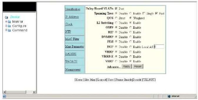
text_image
Device Mon for Configure Command Configuration F Address Clock MTP MAC Filter User Parameter RADIUS PACKS Management Pulley Based VIANs □ Port Spunning Tree □ Double ○ Enable □ Single □ Fast QOS □ Start □ Weighted LI Switching □ Double ○ Enable OSPF □ Enable ○ Enable RIP □ Enable ○ Enable DVMRP □ Enable ○ Enable PIM □ Enable ○ Enable BGP □ Enable ○ Enable Local A5 F VHRP □ Enable ○ Enable VRRP-E □ Enable ○ Enable VSRP □ Enable ○ Enable Advance □ Apply □ Reset [Origin [Site Map [Logic] Site [Prime Attach]Drive [TELNET]NOTE
If you are using Internet Explorer 6.0 to view the Web Management Interface, make sure the version you are running includes the latest service packs. Otherwise, the navigation tree (the left-most pane in Figure 3) will not display properly. For information on how to load the latest service packs, refer to the on-line help provided with your Web browser.
FIGURE 4 First panel for Layer 2 Switch features
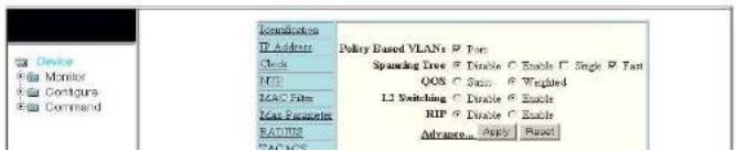
text_image
Device Monitor Contour Command Configuration IP Address Clock HFP IAC Film KoA Parameters RADIUS CAP/APS Policy Based VLANs @ Fan: Spreading Tree @ Disable @ Enable □ Single □ Fan QOS @ Scan: □ Weighted L2 Switching □ Disable □ Enable RIP @ Disable □ Enable Advance □ Apply □ ResetUsing the CLI, you can modify the appearance of the Web Management Interface with the web-management command.
To cause the Web Management Interface to display the List view by default, enter the following command.
PowerConnect(config)#web-management.list-menu
To disable the front panel frame, enter the following command.
PowerConnect(config)#no web-management. Front-panel
When you save the configuration with the write memory command, the changes will take place the next time you start the Web Management Interface, or if you are currently running the Web Management Interface, the changes will take place when you click the Refresh button on your browser.
Using the Web Management Interface
- Click on the plus sign next to Configure in the tree view to expand the list of configuration options.
- Click on the plus sign next to System in the tree view to expand the list of system configuration links.
- Click on the plus sign next to Management in the tree view to expand the list of system management links.
- Click on the Web Preference link to display the Web Management Preferences panel.
- Enable or disable elements on the Web Management Interface by clicking on the appropriate radio buttons on the panel. The following figure identifies the elements you can change.
Logging on through the Web Management Interface
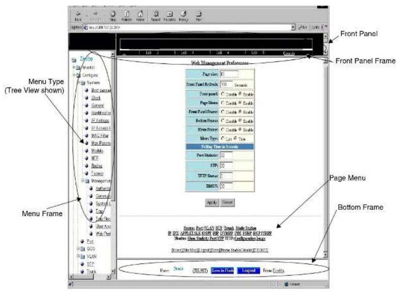
text_image
Front Panel Front Panel Frame Menu Type (Tree View shown) Menu Frame Web Management Preferences Pages: 0 Front Panel Release: 100 Seconds Foreground: C Enable P Enable Page Hidden: C Enable P Enable Front Panel Frame: C Enable P Enable Below Frame: C Enable P Enable New Frame: C Enable P Enable New Type: C Last Type Filing Time to Format Part Subset: 50 STEP: 50 HTTP Status: 5 IMONS: 50 Apply Delete Page Menu Bottom Frame System Port/VLAN STEP Thread Style Station IF NEW APPLYABLE COPY REP ORDER PIN REPIP HELP/ISOP Master Window Selects Port/FTP HTTP Configuration Image Show Auto Web Page Form/Time Tools Help Window (R:1, RGB) Name: Desktop CLOSED Learn to Dash Layout Frame DetailsNOTE
The tree view is available when you use the Web Management Interface with Netscape 4.0 or higher or Internet Explorer 4.0 or higher browsers. If you use the Web Management Interface
Logging on through Brocade Network Advisor
Logging on through Brocade Network Advisor
Refer to the Brocade® Network Advisor manual for information about using Brocade Network Advisor.
Configuring Basic Software Features
Chapter
2
Table 6 lists the individual Dell PowerConnect switches and the basic software features they support.
TABLE 6 Supported basic software features
| Feature PowerConnect B-Series FCX | |
| Basic System Parameters | |
| System name, contact, and location Yes | |
| SNMP trap receiver and trap source address | Yes |
| Disable Syslog messages and traps for CLI access | Yes |
| Cancolling an outbound Telnet session Yes | |
| System time using a Simple Network Time Protocol (SNTP) server or local system counter | Yes |
| System clock Yes | |
| Packet-based broadcast, multicast, and unknown-unicast limits | Yes |
| CLI banners Yes | |
| Local MAC address for Layer 2 management traffic | Yes |
| Basic Port Parameters | |
TABLE 6 Supported basic software features
| Feature PowerConnect B-Series FCX | |
| Auto-negotiation and advertisement of flow control | Yes |
| PHY FIFO Rx and TX Depth Yes | |
| Interpacket Gap (IPG) adjustment Yes | |
| CLI support for 100BaseTX and 100BaseFX | Yes |
| Gbps fiber negotiate mode Yes | |
| QoS priority Yes | |
| VOIP autoconfiguration and CDP Yes | |
| Port flap dampening Yes | |
| Port loop detection Yes | |
Configuring basic system parameters
Dell PowerConnect devices are configured at the factory with default parameters that allow you to begin using the basic features of the system immediately. However, many of the advanced features such as VLANs or routing protocols for the device must first be enabled at the system (global) level before they can be configured. If you use the Command Line Interface (CLI) to configure system parameters, you can find these system level parameters at the Global CONFIG level of the CLI.
NOTE
Before assigning or modifying any router parameters, you must assign the IP subnet (interface) addresses for each port.
NOTE
For information about configuring IP addresses, DNS resolver, DHCP assist, and other IP-related parameters refer to Chapter 26. "Configuring IP"
PowerConnect(config)# hostname zappa
zappa(config)# anmp-server contact Support Services
zappa (config) ≠ snmp-server location Centerville
zappa(config)† end
zappa# write memory
Syntax: hostname
Syntax: snmp-server contact
Syntax: snmp-server location
The text strings can contain blanks. The SNMP text strings do not require quotation marks when they contain blanks but the host name does.
NOTE
The chassis name command does not change the CLI prompt. Instead, the command assigns an administrative ID to the device.
Configuring Simple Network Management Protocol (SNMP) parameters
Use the procedures in this section to perform the following configuration tasks:
- Specify an SNMP trap receiver.
- Specify a source address and community string for all traps sent by the device.
- Change the holddown time for SNMP traps
- Disable individual SNMP traps. (All traps are enabled by default.)
- Disable traps for CLI access that is authenticated by a local user account, a RADIUS server, or a TACACS/TACACS+ server.
NOTE
To add and modify "get" (read-only) and "set" (read-write) community strings, refer to Chapter 32,
"Securing Access to Management Functions".
Specifying an SNMP tran receiver
To specify an SNMP trap receiver and change the UDP port that will be used to receive traps, enter a command such as the following.
PowerConnect(config)# snmp-server host 2.2.2.2 0 mypublic port 200 PowerConnect(config)# write memory
Syntax: snmp-server host
The
The 0 | 1 parameter specifies whether you want the software to encrypt the string (1) or show the string in the clear (0). The default is 0.
The
The command in the example above adds trap receiver 2.2.2.2 and configures the software to encrypt display of the community string. When you save the new community string to the startup-config file (using the write memory command), the software adds the following command to the file.
snmp-server host 2.2.2.2 1
To add a trap receiver and configure the software to encrypt display of the community string in the CLI and Web Management Interface, enter commands such as the following.
PowerConnect(config)# amp-server host 2.2.2.2 0 PowerConnect-12 PowerConnect(config)# write memory
The port
To change the holddown time for SNMP traps, enter a command such as the following at the global CONFIG level of the CLI.
PowerConnect(config)# smp-server enable traps holddown-time 30
The command in this example changes the holddown time for SNMP traps to 30 seconds. The device waits 30 seconds to allow convergence in STP and OSPF before sending traps to the SNMP trap receiver.
Syntax: [no] snmp-server enable traps holddown-time
The
Disabling SNMP traps
Dell PowerConnect devices come with SNMP trap generation enabled by default for all traps. You can selectively disable one or more of the following traps.
NOTE
By default, all SNMP traps are enabled at system startup.
Layer 2 traps
The following traps are generated on devices running Layer 2 software:
- SNMP authentication keys
• Power supply failure - Fan failure
- Cold start
- Link up
- Link down
- Bridge new root
- Bridge topology change
-
Locked address violation
-
OSPF
• VRRP
• VRRPE
To stop link down occurrences from being reported, enter the following.
PowerConnect(config)# no snmp-server enable traps link-down
Syntax: [no] snmp-server enable traps
Disabling Syslog messages and traps for CLI access
Dell PowerConnect devices send Syslog messages and SNMP traps when a user logs into or out of the User EXEC or Privileged EXEC level of the CLI. The feature applies to users whose access is authenticated by an authentication-method list based on a local user account, RADIUS server, or TACACS/TACACS+ server.
NOTE
The Privileged EXEC level is sometimes called the "Enable" level, because the command for accessing this level is enable.
The feature is enabled by default.
Examples of Syslog messages for CLI access
When a user whose access is authenticated by a local user account, a RADIUS server, or a TACACS/TACACS+ server logs into or out of the CLI User EXEC or Privileged EXEC mode, the software generates a Syslog message and trap containing the following information:
- The time stamp
- The user name
- Whether the user logged in or out
• The CLI level the user logged into or out of (User EXEC or Privileged EXEC level)
NOTE
Configuring basic system parameters
PowerConnect# show logging
Syslog logging: enabled (0 messages dropped, 0 flushes, 0 overruns)
Buffer logging: level ACDMEINW, 12 messages logged
level code: A-alert C-critical D-debugging M-emergency E-error
1=informational N=notification W=warning
Static Log Buffer
Dec 15 19:04:14:A:Fan 1, fan on right connector, failed
Dynamic Log Buffer (50 entries):
Oct 15 18:01:11:info:dg logout from USER EXEC mode
Oct 15 17:59:22:info:ag logout from PRIVILEGE EXEC mode
Oct. 15 17:38:07:info:dy login to PRIVILEGE EXEC mode
Oct 15 17:38:03:info:da login to USER EXEC mode
Syntax: show logging
The first message (the one on the bottom) indicates that user "dg" logged in to the CLI User EXEC level on October 15 at 5:38 PM and 3 seconds (Oct 15 17:38:03). The same user logged into the Privileged EXEC level four seconds later.
The user remained in the Privileged EXEC mode until 5:59 PM and 22 seconds. (The user could have used the CONFIG modes as well. Once you access the Privileged EXEC level, no further authentication is required to access the CONFIG levels.) At 6:01 PM and 11 seconds, the user ended the CLI session.
Disabling the Syslog messages and traps
Logging of CLI access is enabled by default. If you want to disable the logging, enter the following commands.
PowerConnect(config)# no logging enable user-login
PowerConnect(config)# write memory
PowerConnect(config)# end
PowerConnect# reload
Syntax: [no] logging enable user-login
Cancelling an outbound Telnet session
NOTE
Dell PowerConnect devices do not retain time and date information across power cycles. Unless you want to reconfigure the system time counter each time the system is reset, Dell PowerConnect recommends that you use the SNTP feature.
To identify an SNTP server with IP address 208.99.8.95 to act as the clock reference for a Dell PowerConnect device, enter the following.
PowerConnect(config)# antp server 208.99.8.95
Syntax: sntp server
The
By default, the Dell PowerConnect device polls its SNTP server every 30 minutes (1800 seconds). To configure the Dell PowerConnect device to poll for clock updates from a SNTP server every 15 minutes, enter the following.
PowerConnect(config)‡ snlp poll-interval 900
Syntax: [no] sntp poll-interval <1-65535>
To display information about SNTP associations, enter the following command.
PowerConnect ^1 show snlp associations
| address | ref clock | st | when | poll | delay | disp |
| -207.95.6.102 | 0.0.0.0 | 16 | 202 | 4 | 0.0 | 5.45 |
| -207.95.6.101 | 0.0.0.0 | 16 | 202 | 0 | 0.0 | 0.0 |
| * synced, - configured | ||||||
Syntax: show sntp associations
The following table describes the information displayed by the show sntp associations command.
TABLE 7 Output from the show sntp associations command
This field... Displays...
PowerConnect# show antp status
Clock is synchronized, stratum = 4, reference clock = 10.70.20.23
precision is 2***-20
reference time is 3489354594.3780510747
clock offset is 0.0000 msec, root delay is 0.41 msec
root dispersion is 0.11 msec, peer dispersion is 0.00 msec
sntp pull-interval is 10 sec
Syntax: show sntp status
The following table describes the information displayed by the show sntp status command.
TABLE 8 Output from the show sntp status command
| This field... Indicates... | |
| unsynchronized System is not synchronized to an NTP peer. | |
| synchronized System is synchronized to an NTP peer. | |
| stratum NTP stratum level of this system | |
| reference clock IP Address of the peer (if any) to which the unit is synchronized | |
| precision Precision of this system's clock (in Hz) | |
| reference time Reference time stamp | |
| clock offset Offset of clock to synchronized peer | |
| root delay | Total delay along the path to the root clock |
| root dispersion | Dispersion of the root path |
| peer dispersion | Dispersion of the synchronized peer |
| sntp poll-interval | Shows how often the Dell PowerConnect device polls for clock updates from an SNTP server. |
Setting the system clock
In addition to SNTP support, Dell PowerConnect switches and routers also allow you to set the custom time counter. The time counter setting is not retained, games power menu and is set
By default, Dell PowerConnect switches and routers do not change the system time for daylight saving time. To enable daylight saving time, enter the following command.
PowerConnect+ clock summer-time
Syntax: clock summer-time
Although SNTP servers typically deliver the time and date in Greenwich Mean Time (GMT), you can configure the Dell PowerConnect device to adjust the time for any one-hour offset from GMT or for one of the following U.S. time zones:
• US Pacific
- Alaska
- Aleutian
• Arizona
- Central
- East-Indiana
- Eastern
- Hawaii
- Michigan
- Mountain
- Pacific
- Samoa
To change the time zone to Australian East Coast time (which is normally 10 hours ahead of GMT), enter the following command.
PowerConnect(config)# clock timezone gmt gmt+10
Syntax: clock timezone gmt | us
You can enter one of the following values for
- US time zones (us): alaska, aleutian, arizona, central, east-indiana, eastern, hawaii, michigan, mountain, pacific, samoa.
Syntax: [no] clock timezone us
Enter pacific, eastern, central, or mountain for
This command must be configured on every device that follows the US DST.
To verify the change, run a show clock command.
PowerConnect # show clock
Refer to October 19, 2006 - Daylight Saving Time 2007 Advisory, posted on kp.foundrynet.com for more information
Limiting broadcast, multicast, and unknown unicast traffic
Dell PowerConnect devices can forward all flooded traffic at wire speed within a VLAN. However, some third-party networking devices cannot handle high rates of broadcast, multicast, or unknown-unicast traffic. If high rates of traffic are being received by the Dell PowerConnect device on a given port of that VLAN, you can limit the number of broadcast, multicast, or unknown-unicast packets or bytes received each second on that port. This can help to control the number of such packets or bytes that are flooded on the VLAN to other devices.
Configuration notes and feature limitations:
• PowerConnect B-Series FCX devices
- To enable unknown-unicast limiting or multicast limiting, enable it after enabling broadcast limiting. Unknown-unicast limiting and multicast limiting use the limit defined in broadcast limiting. You cannot set a separate limit for unknown-unicast limiting and multicast limiting.
- PowerConnect B-Series FCX devices support packet-based limiting only.
Command syntax for packet-based limiting on PowerConnect B-Series FCX devices
To enable broadcast limiting on a group of ports by counting the number of packets received, enter
The
Viewing broadcast, multicast, and unknown unicast limits
You can use the show run interface command to display the broadcast, multicast, and unknown-unicast limits configured on the device.
You can use the following commands, in addition to the show run interface command, to display the broadcast, multicast, and unknown-unicast limits configured on the device:
• show rate-limit unknown-unicast
• show rate-limit broadcast
Use the show run interface command to view the broadcast, multicast, and unknown-unicast limit configured on each port.
Example
PowerConnect ^1 show run interface
interface ethernet 4
broadcast limit 1245184 bytes
multicast limit
interface ethernet 5
broadcast limit 1245184 bytes
multicast limit
interface ethernet 12
unknown-unicast limit 524288
!
interface ethernet 13
unknown-unicast limit 65536 bytes
!
interface ethernet 14
Syntax: show rate-limit unknown-unicast
Use the show rate-limit broadcast command to display the broadcast limit or broadcast and multicast limit for each port to which it applies.
Example
PowerConnect# show rate-limit broadcast
Broadcast/Multicast Limit Settings:
Port Limit Packets/Bytes Packet Type(s)
4 1245184 Bytes Broadcast + Multicast
5 1245184 Bytes Broadcast + Multicast
14 65536 Packets Broadcast only
23 131072 Packets Broadcast + Multicast
Syntax: show rate-limit broadcast
Configuring CLI banners
Dell PowerConnect devices can be configured to display a greeting message on users' terminals when they enter the Privileged EXEC CLI level or access the device through Telnet. In addition, a Dell PowerConnect device can display a message on the Console when an incoming Telnet CLI session is detected.
Setting a message of the day banner
You can configure the Dell PowerConnect device to display a message on a user terminal when he or she establishes a Telnet CLI session. For example, to display the message "Welcome to PowerConnect!" when a Telnet CLI session is established.
PowerConnect(config)# banner motd \$ (Press Return)
Enter TEXT message, End with the character 'S'.
Welcome to PowerConnect!! \$
A delimiting character is established on the first line of the banner motd command. You begin and end the message with this delimiting character. The delimiting character can be any character except " (double-quotation mark) and cannot appear in the banner text. In this example, the
Device
Click the [Login] link to accept and continue the login process...
NOTE
If you are using a Web client to view the message of the day, and your banners are very wide, with large borders, you may need to set your PC display resolution to a number greater than the width of your banner. For example, if your banner is 100 characters wide and the display is set to 80 characters, the banner may distort, or wrap, and be difficult to read. If you set your display resolution to 120 characters, the banner will display correctly.
Requiring users to press the Enter key after the message of the day banner
In earlier IronWare software releases, users were required to press the Enter key after the Message of the Day (MOTD) was displayed, prior to logging in to the Dell PowerConnect device on a console or from a Telnet session. Now, this requirement is disabled by default. Unless configured, users do not have to press Enter after the MOTD banner is displayed.
For example, if the MOTD "Authorized Access Only" is configured, by default, the following messages are displayed when a user tries to access the Dell PowerConnect device from a Telnet session.
Authorized Access Only ...
Username:
The user can then login to the device.
However, if the requirement to press the Enter key is enabled, the following messages are displayed when accessing the switch from Telnet.
To enable the requirement to press the Enter key after the MOTD is displayed, enter a command such as the following.
PowerConnect(config)# banner motd require-enter-key
Syntax: [no] banner motd require-enter-key
Use the no form of the command to disable the requirement.
Setting a privileged EXEC CLI level banner
You can configure the Dell PowerConnect device to display a message when a user enters the Privileged EXEC CLI level.
Example
PowerConnect(config)# banner exec_mode # (Press Return)
Enter TEXT message, End with the character '\$'.
You are entering Privileged EXEC level
Do not foul anything up! †
As with the banner motd command, you begin and end the message with a delimiting character; in this example, the delimiting character is 4(pound sign). The delimiting character can be any character except * (double-quotation mark) and cannot appear in the banner text. The text in between the pound signs is the contents of the banner. Banner text can be up to 4000 characters, which can consist of multiple lines.
Syntax: [no] banner exec_mode
To remove the banner, enter the no banner exec_mode command.
Displaying a console message when an incoming Telnet session is detected
You can configure the Dell PowerConnect device to display a message on the Console when a user establishes a Telnet session. This message indicates where the user is connecting from and displays a configurable text message.
Example
PowerConnect(config)† banner incoming \$ (Press Return)
Configuring a local MAC address for Layer 2 management traffic
By default, Layer 2 devices use the MAC address of the first port as the MAC address for Layer 2 management traffic. For example, when the Dell PowerConnect device receives an ARP request for its management IP address, it responds with the first port MAC address. This may cause problems in some configurations where the Dell PowerConnect device uses the same MAC address for management traffic as for switched traffic.
You can configure the Dell PowerConnect device to use a different MAC address for Layer 2 management traffic than for switched traffic. When you issue the use-local-management-mac, the Dell PowerConnect device changes a local bit in the first port MAC address and uses this MAC address for management traffic. The second bit of the first port MAC address is changed to 2. For example, if the MAC address is 00e0.5201.9900 after the feature is enabled, the switch uses 02e0.5201.9900 for management functions. Switched traffic will continue to use the first port MAC address without the local bit setting.
Example
PowerConnect(config)† use-local-management-mac
PowerConnect{config}# write memory
PowerConnect (config) # end
PowerConnect# reload
Syntax: [no] use-local-management-mac
NOTE
You must save the configuration and reload the software to place the change into effect.
NOTE
This feature is only available for the switch code. It is not available for router code.
Configuring basic port parameters
The procedures in this section describe how to configure the port parameters shown in Table 6.
Modifying port speed and duplex mode
The Gigabit Ethernet copper ports are designed to auto-sense and auto-negotiate the speed and duplex mode of the connected device. If the attached device does not support this operation, you can manually enter the port speed to operate at either 10, 100, or 1000 Mbps. The default and recommended setting is 10/100/1000 auto-sense.
NOTE
You can modify the port speed of copper ports only; this feature does not apply to fiber ports.
NOTE
For optimal link operation, copper ports on devices that do not support 803.3u must be configured with like parameters, such as speed (10,100,1000), duplex (half, full), MDI/MDIX, and Flow Control.
Configuration syntax
The following commands change the port speed of copper interface 8 on a PowerConnect from the default of 10/100/1000 auto-sense, to 100 Mbps operating in full-duplex mode.
PowerConnect(config)# interface ethernet 8
PowerConnect{config-if-e1000-8}# speed-duplex 100-full
Syntax: speed-duplex
where
• 10-full - 10 Mbps, full duplex
• 10-half – 10 Mbps, half duplex
• 100-full - 100 Mbps, full duplex
• 100-half - 100 Mbps, half duplex
• 1000-full-master - 1 Gbps, full duplex master
• 1000-full-slave - 1 Gbps, full duplex slave
- auto - auto-negotiation
Maximum Port speed advertisement and Port speed down-shift are enhancements to the auto-negotiation feature, a mechanism for accommodating multi-speed network devices by automatically configuring the highest performance mode of inter-operation between two connected devices.
Port speed down-shift enables Gbps copper ports on the Dell PowerConnect device to establish a link at 1000 Mbps over a 4-pair wire when possible, or to down-shift to 100 Mbps if the medium is a 2-pair wire.
Maximum port speed advertisement enables you to configure an auto-negotiation maximum speed that Gbps copper ports on the Dell PowerConnect device will advertise to the connected device. You can configure a port to advertise a maximum speed of either 100 Mbps or 10 Mbps. When the maximum port speed advertisement feature is configured on a port that is operating at 100 Mbps maximum speed, the port will advertise 10/100 Mbps capability to the connected device. Similarly, if a port is configured at 10 Mbps maximum speed, the port will advertise 10 Mbps capability to the connected device.
The port speed down-shift and maximum port speed advertisement features operate dynamically at the physical link layer between two connected network devices. They examine the cabling conditions and the physical capabilities of the remote link, then configure the speed of the link segment according to the highest physical-layer technology that both devices can accommodate.
The port speed down-shift and maximum port speed advertisement features operate dynamically at the physical link layer, independent of logical trunk group configurations. Although Dell recommends that you use the same cable types and auto-negotiation configuration on all members of a trunk group, you could utilize the auto-negotiation features conducive to your cabling environment. For example, in certain circumstances, you could configure each port in a trunk group to have its own auto-negotiation maximum port speed advertisement or port speed down-shift configuration.
Application notes
- Port speed down-shift and maximum port speed advertisement work only when auto-negotiation is enabled (CLI command speed-duplex auto). If auto-negotiation is OFF, the device will reject the port speed down-shift and maximum port speed advertisement configuration.
Syntax: [no] link-config gig copper autoneg-control down-shift ethernet
Specify the
• PowerConnect B-Series FCX stackable switches -
You can list all of the ports individually, use the keyword to to specify ranges of ports, or a combination of both.
You can enable port speed down-shift on one or two ports at a time.
To disable port speed down-shift after it has been enabled, enter the no form of the command.
Configuring port speed down-shift and auto-negotiation for a range of ports
Port speed down-shift and auto-negotiation can be configured for an entire range of ports with a single command.
For example, to configure down-shift on ports 0/1/1 to 0/1/10 and 0/1/15 to 0/1/20 on the device, enter the following.
PowerConnect(config) link-config gig copper autoneg-control down-shift ethernet 0/1/1 to 0/1/10 ethernet 0/1/15 to 0/1/20
To configure down-shift on ports 5 to 13 and 17 to 19 on a compact switch, enter the following. PowerConnect{config}# link-config gig copper autoneg-control down-shift ethernet 5 to 13 ethernet 17 to 19
Syntax: [no] link-config gig copper autoneg-control [down-shift | 100m-auto | 10m-auto] ethernet
The
For
• PowerConnect B-Series FCX stackable switches -
You can list all of the ports individually, use the keyword to to specify ranges of ports, or a combination of both. To apply the configuration to all ports on the device, use the keyword all instead of listing the ports individually.
To disable selective auto-negotiation of 100m-auto on ports 0/1/21 to 0/1/25 and 0/1/30, enter the following.
PowerConnect(config)# no link-config gig copper autoneq-control 100m-auto ethernet 0/1/21 to 0/1/25 ethernet 0/1/30
Configuring maximum port speed advertisement
To configure a maximum port speed advertisement of 10 Mbps on a port that has auto-negotiation enabled, enter a command such as the following at the Global CONFIG level of the CLI.
PowerConnect(config)# link-config gig copper autoneg-control 10m ethernet 1
To configure a maximum port speed advertisement of 100 Mbps on a port that has auto-negotiation enabled, enter the following command at the Global CONFIG level of the CLI.
PowerConnect(config)# link-config gig copper autoneg-control 100m ethernet 2
Syntax: [no] link-config gig copper autoneg-control 10m | 100m ethernet
Specify the
• PowerConnect B-Series FCX stackable switches -
You can list all of the ports individually, use the keyword to to specify ranges of ports, or a combination of both.
You can enable maximum port speed advertisement on one or two ports at a time.
To disable maximum port speed advertisement after it has been enabled, enter the no form of the command.
Modifying port duplex mode
You can manually configure a 10/100 Mbps port to accept either full-duplex (bi-directional) or half-duplex (uni-directional) traffic.
Configuring basic port parameters
• 100-half
- auto (default)
Configuring MDI/MDIX
Dell PowerConnect devices support automatic Media Dependent Interface (MDI) and Media Dependent Interface Crossover (MDIX) detection on all Gbps Ethernet Copper ports.
MDI/MDIX is a type of Ethernet port connection using twisted pair cabling. The standard wiring for end stations is MDI, whereas the standard wiring for hubs and switches is MDIX. MDI ports connect to MDIX ports using straight-through twisted pair cabling. For example, an end station connected to a hub or a switch uses a straight-through cable. MDI-to-MDI and MDIX-to-MDIX connections use crossover twisted pair cabling. So, two end stations connected to each other, or two hubs or switches connected to each other, use crossover cable.
The auto MDI/MDIX detection feature can automatically correct errors in cable selection, making the distinction between a straight-through cable and a crossover cable insignificant.
Configuration notes
• This feature applies to copper ports only.
- The mdi-mdix mdi and mdi-mdix mdix commands work independently of auto-negotiation. Thus, these commands work whether auto-negotiation is turned ON or OFF.
- Do not use the mdi-mdix commands on ports that are manually configured with a speed and duplex of 100-full. In this case, make sure the other port (remote end of the connection) is also configured to 100-full and a cross-over cable is used if the connected device is another switch, hub, or router, or a straight-through cable if the connected device is a host NIC.
Configuration syntax
The auto MDI/MDIX detection feature is enabled on all Gbps copper ports by default. For each port, you can disable auto MDI/MDIX, designate the port as an MDI port, or designate the port as an MDIX port.
Disabling or re-enabling a port
A port can be made inactive (disable) or active (enable) by selecting the appropriate status option.
The default value for a port is enabled.
To disable port 8 of a Dell PowerConnect device, enter the following.
PowerConnect(config)4 interface ethernet 8
PowerConnect(config-if-e1000-8)# disable
You also can disable or re-enable a virtual interface. To do so, enter commands such as the
following.
PowerConnect(config)# interface ve vl
PowerConnect(config-vif-1)# disable
Syntax: disable
To re-enable a virtual interface, enter the enable command at the Interface configuration level. For
example, to re-enable virtual interface v1, enter the following command.
PowerConnect(config-vif-1)# enable
Syntax: enable
Configuring flow control
Flow control (802.3x) is a QoS mechanism created to manage the flow of data between two full-duplex Ethernet devices. Specifically, a device that is oversubscribed (is receiving more traffic than it can handle) sends an 802.3x PAUSE frame to its link partner to temporarily reduce the amount of data the link partner is transmitting. Without flow control, buffers would overflow, packets would be dropped, and data retransmission would be required.
All PowerConnect devices support asymmetric flow control, meaning they can receive PAUSE frames but cannot transmit them. In addition, FCX devices also support symmetric flow control, meaning they can both receive and transmit 802.3x PAUSE frames. For details about symmetric flow control, refer to "Configuring symmetric flow control on PowerConnect B-Series FCX devices" on page 40.
Disabling or re-enabling flow control
You can configure the Dell PowerConnect device to operate with or without flow control. Flow control is enabled by default globally and on all full-duplex ports. You can disable and re-enable flow control at the Global CONFIG level for all ports. When enabled globally, you can disable and re-enable flow control on individual ports.
To disable flow control, enter the following command.
PowerConnect(config)# no flow-control
To turn the feature back on, enter the following command.
PowerConnect(config)# flow-control
Syntax: [no] flow-control
NOTE
For optimal link operation, link ports on devices that do not support 803.3u must be configured with like parameters, such as speed (10,100,1000), duplex (half, full), MDI/MDIX, and Flow Control.
Negotiation and advertisement of flow control
By default, when flow control is enabled globally and auto-negotiation is ON, flow control is enabled and advertised on 10/100/1000M ports. If auto-negotiation is OFF or if the port speed was configured manually, then flow control is not negotiated with or advertised to the peer. For details about auto-negotiation, refer to "Modifying port speed and duplex mode" on page 33.
To disable the advertisement of flow control capability on a port, enter the following commands.
PowerConnect{config}† interface ethernet 0/1/21
PowerConnect(config-if-e1000-0/1/21) + no flow-control
To also disable flow control negotiation, enter the following commands.
PowerConnect(config)# interface ethernet 0/1/21
PowerConnect(config-if-e1000-0/1/21)† no flow-control neg-on
Syntax: [no] flow-control [neg-on]
Displaying flow-control status
The show interface
For example, on a PowerConnect Stackable device, issuing the command for 10/100/1000M port 0/1/21 displays the following output.
PowerConnectr show interfaces ethernet 0/1/21
GigabitEthernet0/1/21 is up, line protocol is up
Hardware is GigabitEthernet, address is 00c0.5204.4014 (bia 30c0.5204.4014)
Configured speed auto, actual 100Mbit, configured duplex fdx, actual fdx
Configured rdi mode AUTO, actual MDTX
Member of L2 VLAN ID 1, port is untagged, port state is LISTENING
BPDD Guard is disabled, Root Protect is disabled
STP configured to ON, priority is level0
Flow Control is config enabled, oper enabled, negotiation disabled
Mirror disabled, Monitor disabled
Not member of any active trunks
Not member of any configured trunks
No port name
Inter-Packet Gap (IPG) is 96 bit times
300 second input rate: 0 bits/sec, 0 packets/sec, 0.00% utilization
300 second output rate: 0 bits/sec, 0 packets/sec, 0.00% utilization
0 packets input, 0 bytes, 0 no buffer
Received 0 broadcasts, 0 multicasts, 0 unicasts
0 input errors, 0 CRC, 0 frame, 0 ignored
0 runts, 0 giants
5 packets output, 320 bytes, 0 underruna
Transmitted 0 broadcasts, 5 multicasts, 0 unicasts
0 output errors, 0 collisions
The line highlighted in bold will resemble one of the following, depending on the configuration:
- If flow-control negotiation is enabled (and a neighbor does not negotiate flow control), the display shows:
Flow Control is config enabled, oper disabled, negotiation enabled
• If flow control is enabled, and flow-control negotiation is disabled, the output shows.
Symmetric flow control addresses the requirements of a lossless service class in an Internet Small Computer System Interface (iSCSI) environment. It is supported on FCX standalone units as well as on all FCX units in an IronStack.
About XON and XOFF thresholds
An 802.3x PAUSE frame is generated when the buffer limit at the ingress port reaches or exceeds the port's upper watermark threshold (XOFF limit). The PAUSE frame requests that the sender stop transmitting traffic for a period of time. The time allotted enables the egress and ingress queues to be cleared. When the ingress queue falls below the port's lower watermark threshold (XON limit), an 802.3x PAUSE frame with a quanta of 0 (zero) is generated. The PAUSE frame requests that the sender resume sending traffic normally.
Each 1G and 10G port is configured with a default total number of buffers as well as a default XOFF and XON threshold. The defaults are different for 1G ports versus 10G ports. Also, the default XOFF and XON thresholds are different for jumbo mode versus non-jumbo mode. The defaults are shown in Table 9.
TABLE 9 XON and XOFF default thresholds
| Limit when Jumbo disabled / % of buffer limit | Limit when Jumbo enabled / % of buffer limit | |
| 1G ports | ||
| Total buffers 272 272 | ||
| XOFF 240 / 91% 216 / 82% | ||
| XON 200 / 75% 184 / 70% | ||
| 10G ports | ||
| Total buffers 416 416 | ||
| XOFF 376 / 91% 336 / 82% | ||
| XON 312 / 75% | 288 / 70% | |
If necessary, you can change the total buffer limits and the XON and XOFF default thresholds. Refer
• The following QoS features are not supported together with symmetric flow control:
- Dynamic buffer allocation (CLI commands qd-descriptor and qd-buffer)
- Buffer profiles (CLI command buffer-profile port-region)
- DSCP-based QoS (CLI command trust dscp)
NOTE
Although the above QoS features are not supported with symmetric flow control, the CLI will still accept these commands. The last command issued will be the one placed into effect on the device. For example, if trust dscp is enabled after symmetric-flow-control is enabled, symmetric flow control will be disabled and trust dscp will be placed into effect. Make sure you do not enable incompatible QoS features when symmetric flow control is enabled on the device.
- Head of Line (HOL) blocking may occur when symmetric flow control is enabled. This means that a peer can stop transmitting traffic streams unrelated to the congestion stream.
Enabling and disabling symmetric flow control
By default, symmetric flow control is disabled and tail drop mode is enabled. However, because flow control is enabled by default on all full-duplex ports, these ports will always honor received 802.3x Pause frames, whether or not symmetric flow control is enabled.
To enable symmetric flow control globally on all full-duplex data ports of a standalone unit, enter the following command.
PowerConnect(config)# symmetric-flow-control enable
To enable symmetric flow control globally on all full-duplex data ports of a particular unit in an IronStack, enter a command such as the following.
PowerConnect(config)# symmetric-flow-control enable unit 4
Syntax: [no] symmetric-flow-control enable [unit
The
Configuring basic port parameters
Syntax: symmetric-flow-control set 1 | 2 xoff <%>xon <%>
symmetric-flow-control set 1 sets the XOFF and XON limits for 1G ports.
symmetric-flow-control set 2 sets the XOFF and XON limits for 10G ports.
For xoff <%> , the <%> minimum value is 60% and the maximum value is 95%.
For xon <%> , the <%> minimum value is 50% and the maximum value is 90%.
Use the show symmetric command to view the default or configured XON and XOFF thresholds. Refer to "Displaying symmetric flow control status" on page 43.
Changing the total buffer limits
This section describes how to change the total buffer limits described in "About XON and XOFF thresholds" on page 41. You can change the limits for all 1G ports and for all 10G ports.
To change the total buffer limit for all 1G ports, enter a command such as the following.
PowerConnect(config)# symmetric-flow-control set.1 buffers 320
Total buffers modified, 1G: 320, 10G: 128
To change the total buffer limit for all 10G ports, enter a command such as the following.
PowerConnect{config}# symmetric-flow-control set 2 buffers 128
Total buffers modified, 1G: 320, 10G: 128
Syntax: symmetric-flow-control set 1 | 2 buffers
symmetric-flow-control set 1 buffers
symmetric-flow-control set 2 buffers
Use the show symmetric command to view the default or configured total buffer limits. Refer to "Displaying symmetric flow control status" on page 43.
Displaying symmetric flow control status
Configuring PHY FIFO Rx and Tx depth
PHY devices on PowerConnect B-Series FCX devices contain transmit and receive synchronizing FIFOs to adjust for frequency differences between clocks. The phy-filo-depth command allows you to configure the depth of the transmit and receive FIFOs. There are 4 settings (0-3) with 0 as the default. A higher setting indicates a deeper FIFO.
The default setting works for most connections. However, if the clock differences are greater than the default will handle, CRCs and errors will begin to appear on the ports. Raising the FIFO depth setting will adjust for clock differences.
Dell recommends that you disable the port before applying this command, and re-enable the port. Applying the command while traffic is flowing through the port can cause CRC and other errors for any packets that are actually passing through the PHY while the command is being applied.
Syntax: [no] phy-fifo-depth
-
This command can be issued for a single port from the IF config mode or for multiple ports from the MIF config mode.
NOTE
Higher settings give better tolerance for clock differences with the partner phy, but may marginally increase latency as well.
Configuring the IPG on PowerConnect Stackable devices
On PowerConnect B-Series FCX devices, you can configure an IPG for each port. An IPG is a configurable time delay between successive data packets.
You can configure an IPG with a range from 48-120 bit times in multiples of 8, with a default of 96. The IPG may be set from either the interface configuration level or the multiple interface level.
Configuration notes
This version describes the configuration processes for DevusOmnest Optable devices
Syntax: [no] ipg
For value, enter a number in the range from 48-120 bit times in multiples of 8. The default is 96.
As a result of the above configuration, the output from the show interface Ethernet 0/1/21 command is as follows.
PowerConnect show interfaces ethernet 0/1/21
GigabitEthernet 0/1/21 is up, line protocol is up
Hardware is GigabitEthernet, address is 00e0.5204.4014 (bia 00e0.5204.4014)
Configured speed auto, actual 100MHz, configured duplex fdx, actual fdx
Configured rdi mode AUTO, actual MDTX
Member of L2 VLAN ID 1, port is untagged, port state is FORWARDING
BPDJ Guard is disabled, Root Protect is disabled
STP configured to ON, priority is level0
Flow Control is config enabled, oper enabled, negotiation disabled
Mirror disabled, Monitor disabled
Not member of any active trunks
Not member of any configured trunks
No port name
Inter-Packet Gap (IPG) is 112 bit times
TP MTU 10222 bytes
300 second input rate: 0 bits/sec, 0 packets/sec, 0.00% utilization
300 second output rate: 248 bits/sec, 0 packets/sec, 0.00% utilization
0 packets input, 0 bytes, 0 no buffer
Received 0 broadcasts, 0 multicasts, 0 unicasts
0 input errors, 0 CRC, 0 frame, 0 ignored
0 runts, 0 giants
80 packets output, 5120 bytes, 0 underruns
Transmitted 0 broadcasts, 80 multicasts, 0 unicasts
0 output errors, 0 collisions
Enabling and disabling support for 100BaseTX
Configuration notes
• This feature requires that autonegotiation be enabled on the other end of the link.
Chassis-based and Stackable devices
NOTE
The following procedure applies to Stackable devices and to Chassis-based 100/1000 Fiber interface modules only. The CLI syntax for enabling and disabling 100BaseFX support on these devices differs than on a Compact device. Make sure you refer to the appropriate procedures.
PowerConnect devices support the following types of SFPs for 100BaseFX:
- Multimode SFP – maximum distance is 2 kilometers
- Bidirectional single mode SFP – maximum distance is 10 kilometers
- Long Reach (LR) – maximum distance is 40 kilometers
• Intermediate Reach (IR) – maximum distance is 15 kilometers
NOTE
Connect the 100BaseFX fiber transceiver after configuring both sides of the link. Otherwise, the link could become unstable, fluctuating between up and down states.
To enable support for 100BaseFX on an fiber port or on a Stackable switch, enter commands such as the following.
PowerConnect(config)# interface ethernet. 1/6 PowerConnect(config-if-1/6)# 100-fx
The above commands enable 100BaseFX on port 6 in slot 1.
Syntax: [no] 100-fx
To disable 100BaseFX support on a fiber port, enter the no form of the command. Note that you must disable 100BaseFX support before inserting a different type of module in the same port. Otherwise, the device will not recognize traffic traversing the port.
Changing the Gbps fiber negotiation mode
The globally configured Gbps negotiation mode is the default mode for all Gbps fiber ports. You
Theorem 2.1. (A) Let f , be a finite field, and let f be the set of f -scales in the f -fuller space.
NOTE
When Gbps negotiation mode is turned off (CLI command gig-default neg-off), the Dell device may inadvertently take down both ends of a link. This is a hardware limitation for which there is currently no workaround.
Modifying port priority (QoS)
You can give preference to the inbound traffic on specific ports by changing the Quality of Service (QoS) level on those ports. For information and procedures, refer to Chapter 17, "Configuring Quality of Service".
Dynamic configuration of Voice over IP (VoIP) phones
You can configure a PowerConnect device to automatically detect and re-configure a VoIP phone when it is physically moved from one port to another within the same device. To do so, you must configure a voice VLAN ID on the port to which the VoIP phone is connected. The software stores the voice VLAN ID in the port database for retrieval by the VoIP phone.
The dynamic configuration of a VoIP phone works in conjunction with the VoIP phone discovery process. Upon installation, and sometimes periodically, a VoIP phone will query the Dell PowerConnect device for VoIP information and will advertise information about itself, such as, device ID, port ID, and platform. When the Dell PowerConnect device receives the VoIP phone query, it sends the voice VLAN ID in a reply packet back to the VoIP phone. The VoIP phone then configures itself within the voice VLAN.
As long as the port to which the VoIP phone is connected has a voice VLAN ID, the phone will configure itself into that voice VLAN. If you change the voice VLAN ID, the software will immediately send the new ID to the VoIP phone, and the VoIP phone will re-configure itself with the new voice VLAN.
Configuration notes
• This feature works with any VoIP phone that:
Enabling dynamic configuration of a Voice over IP (VoIP) phone
You can create a voice VLAN ID for a port, or for a group of ports.
To create a voice VLAN ID for a port, enter commands such as the following.
PowerConnect(config) ^4 interface ethernet. 2
PowerConnect(config-if-e1000-2)# voice-vlan 1001
To create a voice VLAN ID for a group of ports, enter commands such as the following.
PowerConnect(config)# interface ethernet 1-8
PowerConnect(config-mif-1-8)‡ voice-vlan 1001
Syntax: [no] voice-vlan
where
To remove a voice VLAN ID, use the no form of the command.
Viewing voice VLAN configurations
You can view the configuration of a voice VLAN for a particular port or for all ports.
To view the voice VLAN configuration for a port, specify the port number with the show voice-vlan command. The following example shows the command output results.
PowerConnect# show voice-vlan ethernet 2
Voice vlan ID for port 2: 1001
The following example shows the message that appears when the port does not have a configured voice VLAN.
PowerConnect# show voice-vlan ethernet 2
Voice vlan is not configured for port 2.
To view the voice VLAN for all ports, use the show voice-vlan command. The following example shows the command output results.
If the port link state toggles from up to down for a specified number of times within a specified period, the interface is physically disabled for the specified wait period. Once the wait period expires, the port link state is re-enabled. However, if the wait period is set to zero (0) seconds, the port link state will remain disabled until it is manually re-enabled.
Configuration notes
- When a flap dampening port becomes a member of a trunk group, that port, as well as all other member ports of that trunk group, will inherit the primary port configuration. This means that the member ports will inherit the primary port flap dampening configuration, regardless of any previous configuration.
- The Dell PowerConnect device counts the number of times a port link state toggles from "up to down", and not from "down to up".
- The sampling time or window (the time during which the specified toggle threshold can occur before the wait period is activated) is triggered when the first "up to down" transition occurs.
- "Up to down" transitions include UDLD-based toggles, as well as the physical link state.
Configuring port flap dampening on an interface
This feature is configured at the interface level.
PowerConnect(config)# interface ethernet 2/1
PowerConnect(config-if-e10000-2/1)# link-error-disable 10 3 10
Syntax: [no] link-error-disable
The
The
The
PowerConnect(config)# interface ethernet 2/1
PowerConnect(config-if-e10000-2/1)# no link-error-disable 10 3 10
Displaying ports configured with port flap dampening
Ports that have been disabled due to the port flap dampening feature are identified in the output of the show link-error-disable command. The following shows an example output.
PowerConnect# show link-error-disable
Port 2/1 is forced down by link-error-disable.
Use the show link-error-disable all command to display the ports with the port flap dampening feature enabled.
For PowerConnect Stackable devices, the output of the command shows the following.
PowerConnect# show link-error-disable all
Port8/1 is configured for link-error-disable threshold:1, sampling_period:10, waiting_period:0
Port8/2 is configured for link-error-disable threshold:1, sampling_period:10, waiting_period:0
Port8/3 is configured for link-error-disable threshold:1, sampling_period:10, waiting_period:0
Port8/4 is configured for link-error-disable threshold:1, sampling_period:10, waiting_period:0
Port8/5 is configured for link-error-disable threshold:4, sampling_period:10, waiting_period:2
Port8/9 is configured for link-error-disable threshold:2, sampling_period:20, waiting_period:0
Table 10 defines the port flap dampening statistics displayed by the show link-error-disable all command.
TABLE 10 Output of show link-error-disable
This column... Displays...
TABLE 10 Output of show link-error-disable (Continued)
| This column... Displays... | |
| State The port state can be one of the following: | |
| Idle - The link is normal and no link state toggles have been detected or sampled.Down - The port is disabled because the number of sampled errors exceeded the configured threshold.Err - The port sampled one or more errors. | |
| Counter | If the port state is Idle, this field displays N/A.If the port state is Down, this field shows the remaining value of the shutoff timer.If the port state is Err, this field shows the number of errors sampled. |
Syntax: show link-error-disable [all]
Example
PowerConnect# show interface ethernet 15
GigabitEthernet15 is up, line protocol is up
Link Error Dampening is Enabled
Hardware is GigabitEthernet, address is 00e0.5200.010e (bia 00e0.5200.010e)
GigabitEthernet17 is ERR-DISABLED, line protocol is down
Link Error Dampening is Enabled
Hardware is GigabitEthernet, address is 00e0.5200.010e (b1a 00e0.5200.010e)
Configured speed auto, actual unknown, configured duplex fdx, actual unknown
The line "Link Error Dampening" displays "Enabled" if port flap dampening is enabled on the port or "Disabled" if the feature is disabled on the port. The feature is enabled on the ports in the two examples above. Also, the characters "ERR-DISABLED" is displayed for the "GbpsEthernet" line if the port is disabled because of link errors.
Port loop detection
This feature allows the Dell PowerConnect device to disable a port that is on the receiving end of a loop by sending test packets. You can configure the time period during which test packets are sent.
Strict mode and loose mode
There are two types of loop detection; Strict Mode and Loose Mode. In Strict Mode, a port is disabled only if a packet is looped back to that same port. Strict Mode overcomes specific hardware issues where packets are echoed back to the input port. In Strict Mode, loop detection must be configured on the physical port.
In Loose Mode, loop detection is configured on the VLAN of the receiving port. Loose Mode disables the receiving port if packets originate from any port or VLAN on the same device. The VLAN of the receiving port must be configured for loop detection in order to disable the port.
Recovering disabled ports
Once a loop is detected on a port, it is placed in Err-Disable state. The port will remain disabled until one of the following occurs:
• You manually disable and enable the port at the Interface Level of the CLI.
- You enter the command clear loop-detection. This command clears loop detection statistics and enables all Err-Disabled ports.
- The device automatically re-enables the port. To set your device to automatically re-enable Err-Disabled ports, refer to "Configuring the device to automatically re-enable ports" on page 53.
Configuration notes
- Loopback detection packets are sent and received on both tagged and untagged ports. Therefore, this feature cannot be used to detect a loop across separate devices.
The following information applies to Loose Mode loop detection:
loops because STP cannot prevent loops across different VLANs. In these instances, the ports are not blocked and loop detection is able to send out probe packets in one VLAN and receive packets in another VLAN. In this way, loop detection running in Loose Mode disables both ingress and egress ports.
Enabling loop detection
Use the loop-detection command to enable loop detection on a physical port (Strict Mode) or a VLAN (Loose Mode). Loop detection is disabled by default. The following example shows a Strict Mode configuration.
PowerConnect(config)# interface ethernet 1/1 PowerConnect(config if e1000-1/1)# loop-detection
The following example shows a Loose Mode configuration.
PowerConnect(config)# vlan20 PowerConnect(config-vlan-20)# loop-detection
By default, the port will send test packets every one second, or the number of seconds specified by the loop-detection-interval command. Refer to "Configuring a global loop detection interval" on page 53.
Syntax: [no] loop-detection
Use the [no] form of the command to disable loop detection.
Configuring a global loop detection interval
The loop detection interval specifies how often a test packet is sent on a port. When loop detection is enabled, the loop detection time unit is 0.1 second, with a default of 10 (one second). The range is from 1 (one tenth of a second) to 100 (10 seconds). You can use the show loop-detection status command to view the loop detection interval.
To configure the global loop detection interval, enter a command similar to the following.
PowerConnect(config)# loop-detection-interval 50
This command sets the loop detection interval to 5 seconds (50 x 0.1)
The above command will cause the Dell PowerConnect device to automatically re-enable ports that were disabled because of a loop detection. By default, the device will wait 300 seconds before re-enabling the ports. You can optionally change this interval to a value from 10 to 65535 seconds. Refer to "Specifying the recovery time interval" on page 54.
Syntax: [no] errdisable recovery cause loop-detection
Use the [no] form of the command to disable this feature.
Specifying the recovery time interval
The recovery time interval specifies the number of seconds the Dell PowerConnect device will wait before automatically re-enabling ports that were disabled because of a loop detection. (Refer to "Configuring the device to automatically re-enable ports" on page 53.) By default, the device will wait 300 seconds. To change the recovery time interval, enter a command such as the following. PowerConnect(config)# errdisable recovery interval i20
The above command configures the device to wait 120 seconds (2 minutes) before re-enabling the ports.
To revert back to the default recovery time interval of 300 seconds (5 minutes), enter one of the following commands.
PowerConnect(config)# errdisable recovery interval 300
OR
PowerConnect(config)# no errdisable recovery interval 120
Syntax: [no] errdisable recovery interval
where
Clearing loop-detection
To clear loop detection statistics and re-enable all ports that are in Err-Disable state because of a loop detection, enter the following command.
PowerConnect# clear loop-detection
If a port is errdisabled in Strict mode, it shows "ERR-DISABLE by itself". If it is errdisabled due to its associated vlan, it shows "ERR-DISABLE by vlan?"
The following command displays the current disabled ports, including the cause and the time.
PowerConnect# show loop-detection disable
Number of err-disabled ports: 3
You can re-enable err-disable ports one by one by "disable" then "enable"
under interface config, re-enable all by "clear loop-detect", or
configure "erralisable recovery cause loop-detection" for automatic recovery index, next, ground-by, discharging
- _1 p02c _2 dausia by _3 disabird a this
- _4 d67 _5 d68
1 1/10 Itzell 60:23:50 2 1/19 vlnn 12 60:17:30
- 1) 1.5 v = _1 - _2 出 t = _1 + _2
This example shows the disabled ports, the cause, and the time the port was disabled. If loop-detection is configured on a physical port, the disable cause will show "itself". For VLANs configured for loop detection, the cause will be a VLAN.
The following command shows the hardware and software resources being used by the loop-detection feature.
Vlans configured loop-detection use 1 HW MAC
Vlans not configured but use HW MAC: 1 10
| alloc | in-use | avail | get-fail | limit | get-mem | size | init | |
| configuration pool | 16 | 6 | 10 | 0 | 3712 | 6 | 15 | 16 |
| linklist pool | 16 | 10 | 6 | 0 | 3712 | 10 | 16 | 16 |
Displaying loop detection resource information
Use the show loop-detection resource command to display the hardware and software resource information on loop detection.
PowerConnect# show loop-detection resource
Vlans configured loop-detection use 1 HW MAC
Vlans not configured but use HW MAC: 1 10
TABLE 11 Field definitions for the show loop-detection resource command (Continued)
| This field... Describes... |
| get-mem The number of get-memory requests |
| size The size |
| init The number of requests initiated |
Syslog message
The following message is logged when a port is disabled due to loop detection. This message also appears on the console.
loop-detect: port ?\?\vlan ?, into errdisable state
The Errdisable function logs a message whenever it re-enables a port.
Operations, Administration, and Maintenance
Chapter
Table 12 lists the individual Dell PowerConnect switches and the operations, administration, and maintenance features they support.
TABLE 12 Supported operations, administration, and maintenance features
| Feature PowerConnect B-Series FCX | |
| Flash and boot code verification | Yes |
| Flash image verification | Yes |
| Software upgrade via CLI | Yes |
| Software upgrade via SNMP | Yes |
| Hitless management:• Hitless switchover• Hitless failover• Hitless OS upgrade | YesRefer to"PowerConnect B-Series FCX hitless stacking" on page 162 |
| Block size for TFTP file transfers | Yes |
| Software reboot | Yes |
| Show boot preference | Yes |
| Load and save configuration files | Yes |
| System reload scheduling | Yes |
| Diagnostic error codes and remedies for TFTP transfers | Yes |
| IPv4 ping | Yes |
| IPv4 traceroute | Yes |
Determining the software versions installed and running on a device
You can update the software contained on a flash module using TFTP to copy the update image from a TFTP server onto the flash module. In addition, you can copy software images and configuration files from a flash module to a TFTP server.
NOTE
Dell PowerConnect devices are TFTP clients but not TFTP servers. You must perform the TFTP transaction from the Dell PowerConnect device. You cannot "put" a file onto the Dell PowerConnect device using the interface of your TFTP server.
NOTE
If you are attempting to transfer a file using TFTP but have received an error message, refer to "Diagnostic error codes and remedies for TFTP transfers" on page 75.
Determining the software versions installed and running on a device
Use the following methods to display the software versions running on the device and the versions installed in flash memory.
Determining the flash image version running on the device
To determine the flash image version running on a device, enter the show version command at any level of the CLI. Some examples are shown below.
Compact devices
To determine the flash image version running on a Compact device, enter the show version command at any level of the CLI. The following shows an example output.
PowerConnect#show version
SW: Version 7.2.00aT53 Copyright (c) 2009 Brocade Communications Systems, Inc. Compiled on Mar 26 2003 at 13:50:31 labeled as FERO 7.2.00a (3089381 bytes) from Primary for 7.2.00a.bin
H2: Checksh1 = PES2402-PREM-TLP
Determining the boot image version running on the device
To determine the boot image running on a device, enter the show flash command at any level of the CLI. The following shows an example output.
PowerConnect#show flash
Active Management Module (slot 9):
Compressed Pri Code size = 3613675, Version 03.1.00aT3e3 (sxr03100a.bin)
Compressed Seq: Code size = 2250218, Version 03.1.00sT3e1 (sxr03100a.bin)
Compressed BootROM Code size = 524288, Version 03.0.01T3e5
Code Flash Free Space = 9659328
Standby Management Module (slot 10):
Compressed Pri Code size = 3613675, Version 03.1.00aT3e3 (sxr03100a.bin)
Compressed Seq: Code size = 2250218, Version 03.1.00sT3e1 (sxr03100a.bin)
Compressed BootROM Code size = 524288, Version  03.0.01T3e5
Code Flash Free Space = 524288
The boot code version is shown in bold type.
Determining the image versions installed in flash memory
Enter the show flash command to display the boot and flash images installed on the device. An example of the command output is shown in "Determining the boot image version running on the device" on page 59:
- The "Compressed Pri Code size" line lists the flash code version installed in the primary flash area.
- The "Compressed Sec Code size" line lists the flash code version installed in the secondary flash area.
- The "Boot Monitor Image size" line lists the boot code version installed in flash memory. The device does not have separate primary and secondary flash areas for the boot image. The flash memory module contains only one boot image.
If TFTP was used to install the file on the Dell PowerConnect device, the path may also be displayed with the filename in the show flash output. For example (path1/SXR05100.bin).
CLI commands
Use the following command syntax to verify the flash image:
Syntax: verify md5 | sha1 | crc32
- md5 - Generates a 16-byte hash code
- sha1 - Generates a 20-byte hash code
- crc32 - Generates a 4 byte checksum
- ascii string - A valid image filename
- primary – The primary boot image (primary.img)
• secondary – The secondary boot image (secondary.img)
- hash code - The hash code to verify
The following examples show how the verify command can be used in a variety of circumstances.
To generate an MD5 hash value for the secondary image, enter the following command.
PowerConnect#verify md5 secondary
PowerConnect....Done
Size - 2044830, MD5 01c410d6d153189a4a5d36c955653862
To generate a SHA-1 hash value for the secondary image, enter the following command.
PowerConnect#verify sha secondary
PowerConnect....Done
Size = 2044830, SHA1 49d12d26552072337f7f5fcaef4cf4b742a9f525
To generate a CRC32 hash value for the secondary image, enter the following command.
PowerConnect#verify crc32 secondary
PowerConnect ^1 ......Done
Size - 2044830, CRC32 b31fcbc0
To verify the hash value of a secondary image with a known value, enter the following commands.
PowerConnect#verify md5 secondary 01c410d6d153189a4a5d36c955653861
PowerConnect ^1 ......Done
Size = 2044830, MD5 01c410d6d153189a4a5d36c955653862
Image file types
This section lists the boot and flash image file types supported and how to install them on the PowerConnect family of switches. For information about a specific version of code, refer to the release notes.
TABLE 13 Software image files
| Product Boot image | 1 | Flash image |
| PowerConnect B-Series FCX GRZxxxxxx.bin FCXSxxxxx.bin (Layer 2) or FCXRxxxxx.bin (Layer 3) | ||
Viewing the contents of flash files
The copy flash console command can be used to display the contents of a configuration file, backup file, or renamed file stored in flash memory. The file contents are displayed on the console when the command is entered at the CLI.
To display a list of files stored in flash memory, do one of the following:
- For PowerConnect B-Series FCX devices, enter the show dir command at any level of the CLI, or enter the dir command at the boot-monitor mode.
The following shows an example command output.
PowerConnect#show dir
133 [38f4] boot-parameter
[ffff] boatram
3802772 [0000] primary
4867691 [0000] secondary
163 [dd8e] stacking.boot
1773 [0d2d] startup-config
1808 [acfa] startup-config.backup
8674340 bytes 7 File(s)
56492032 bytes free
PowerConnect:copy flash console startup-config.backup
vor vor 7.2.00aT7f1!
stack unit 1
    module 1 FCX-24-port-management-module
    module 2 FCX-cx4-2-port-16g module
    module 3 FCX-xfp-2-port-16g-module
    priority 80
    stack port 1/2/1 1/2/2
stack unit 2
    module 1 FCX-48-port-management-module
    module 2 FCX-cx4-2-port-16g-module
    module 3 FCX-xfp-2-port-16g-module
    stack port 2/2/1 2/2/2
stack enable
!
!
!
!
vlan 1 name DEFAULT-VLAN by port
no spanning-tree
metro-rings 1
motro-ring 1
    master
    ring-interfaces ethernet 1/1/2 ethernet 1/1/3
    enable
!
vlan 10 by port
mac-vlan-permit ethe 1/1/5 to 1/1/6 ethe 2/1/5 to 2/1/6 no spanning-tree !
vlan 20 by port
untagged ethe 1/1/7 to 1/1/8
no spanning-tree
pvlan type primary
pvlan mapping 40 ethe 1/1/8
pvlan mapping 30 ethe 1/1/7
!
vlan 30 by port
untagged ethe 1/1/9 to 1/1/10
no spanning-tree
pvlan type community
- Configure a read-write community string on the Dell PowerConnect device, if one is not already configured. To configure a read-write community string, enter the following command from the global CONFIG level of the CLI.
snmp-server community
where
- On the Dell PowerConnect device, enter the following command from the global CONFIG level of the CLI.
no snmp-server pw-check
This command disables password checking for SNMP set requests. If a third-party SNMP management application does not add a password to the password field when it sends SNMP set requests to a Dell PowerConnect device, by default the Dell PowerConnect device rejects the request.
Changing the block size for TFTP file transfers
When you use TFTP to copy a file to or from a Dell PowerConnect device, the device transfers the data in blocks of 8192 bytes by default. You can change the block size to one of the following if needed:
You can use boot commands to immediately initiate software boots from a software image stored in primary or secondary flash on a Dell PowerConnect device or from a BootP or TFTP server. You can test new versions of code on a Dell PowerConnect device or choose the preferred boot source from the console boot prompt without requiring a system reset.
NOTE
It is very important that you verify a successful TFTP transfer of the boot code before you reset the system. If the boot code is not transferred successfully but you try to reset the system, the system will not have the boot code with which to successfully boot.
By default, the Dell device first attempts to boot from the image stored in its primary flash, then its secondary flash, and then from a TFTP server. You can modify this booting sequence at the global CONFIG level of the CLI using the boot system... command.
To initiate an immediate boot from the CLI, enter one of the boot system... commands.
Configuration notes
- If you are booting the device from a TFTP server through a fiber connection, use the following command: boot system tftp
fiber-port. - In an IronStack, the boot system tftp
command will cause the system to boot the active unit with the image specified in the command. The rest of the units in the stack will boot with the primary or secondary image, depending on their boot configuration.
Displaying the boot preference
Use the show boot-preference command to display the boot sequence in the startup config and running config files. The boot sequence displayed is also identified as either user-configured or the default.
The following example shows the default hout sequence preference
The results of the show run command for the configured example above appear as follows.
PowerConnect #show run
Current Configuration:
ver 7.2.00aT7f1
module 1 FCX-48-port-management-module
module 2 FCX-xfp-2-port-16g-module
module 3 FCX-xfp-2-port-16g-module
alias cp-copy tf 10.1.1.1 FCX04000bl.bin pri
!
boot sys fl sec
boot sys df 10.1.1.1 FCX04000bl.bin
boot sys fl pri
ip address 10.1.1.4 255.255.255.0
snmp-client 10.1.1.1
end
Loading and saving configuration files
For easy configuration management, all Dell PowerConnect devices support both the download and upload of configuration files between the devices and a TFTP server on the network.
You can upload either the startup configuration file or the running configuration file to the TFTP server for backup and use in booting the system:
- Startup configuration file – This file contains the configuration information that is currently saved in flash. To display this file, enter the show configuration command at any CLI prompt.
- Running configuration file – This file contains the configuration active in the system RAM but not yet saved to flash. These changes could represent a short-term requirement or general configuration change. To display this file, enter the show running-config or write terminal command at any Q1 prompt.
To replace the startup configuration with the running configuration, enter the following command at any Enable or CONFIG command prompt.
PowerConnect+write memory
Replacing the running configuration with the startup configuration
If you want to back out of the changes you have made to the running configuration and return to the startup configuration, enter the following command at the Privileged EXEC level of the CLI.
PowerConnect+reload
Logging changes to the startup-config file
You can configure a Dell PowerConnect device to generate a Syslog message when the startup config file is changed. The trap is enabled by default.
The following Syslog message is generated when the startup-config file is changed.
startup-config was changed
If the startup-config file was modified by a valid user, the following Syslog message is generated.
startup-config was changed by
To disable or re-enable Syslog messages when the startup-config file is changed, use the following command.
Syntax: [no] logging enable config-changed
Copying a configuration file to or from a TFTP server
To copy the startup-config or running-config file to or from a TFTP server, use one of the following methods.
NOTE
For details about the copy and ncopy commands used with IPv6, refer to "Using the IPv6 copy
Dynamic configuration loading
You can load dynamic configuration commands (commands that do not require a reload to take effect) from a file on a TFTP server into the running-config on the Dell PowerConnect device. You can make configuration changes off-line, then load the changes directly into the device running-config, without reloading the software.
Usage considerations
- Use this feature only to load configuration information that does not require a software reload to take effect. For example, you cannot use this feature to change statically configured memory (system-max command) or to enter trunk group configuration information into the running-config.
- Do not use this feature if you have deleted a trunk group but have not yet placed the changes into effect by saving the configuration and then reloading. When you delete a trunk group, the command to configure the trunk group is removed from the device running-config, but the trunk group remains active. To finish deleting a trunk group, save the configuration (to the startup-config file), then reload the software. After you reload the software, then you can load the configuration from the file.
- Do not load port configuration information for secondary ports in a trunk group. Since all ports in a trunk group use the port configuration settings of the primary port in the group, the software cannot implement the changes to the secondary port.
Preparing the configuration file
A configuration file that you create must follow the same syntax rules as the startup-config file the device creates.
- The configuration file is a script containing CLI configuration commands. The CLI reacts to each command entered from the file in the same way the CLI reacts to the command if you enter it. For example, if the command results in an error message or a change to the CLI configuration level, the software responds by displaying the message or changing the CLI level.
- The software retains the running-config that is currently on the device, and changes the running config only by adding new commands from the configuration file. If the running config
NOTE
If you copy-and-paste a configuration into a management session, the CLI ignores the " ! " instead of changing the CLI to the global CONFIG level. As a result, you might get different results if you copy-and-paste a configuration instead of loading the configuration using TFTP.
- Make sure you enter each command at the correct CLI level. Since some commands have identical forms at both the global CONFIG level and individual configuration levels, if the CLI response to the configuration file results in the CLI entering a configuration level you did not intend, then you can get unexpected results.
For example, if a trunk group is active on the device, and the configuration file contains a command to disable STP on one of the secondary ports in the trunk group, the CLI rejects the commands to enter the interface configuration level for the port and moves on to the next command in the file you are loading. If the next command is a spanning-tree command whose syntax is valid at the global CONFIG level as well as the interface configuration level, then the software applies the command globally. Here is an example.
The configuration file contains these commands.
interface ethernet 2 no spanning-tree
The CLI responds like this.
PowerConnect(config)#interface ethernet 2 Error - cannot configure secondary ports of a trunk PowerConnect(config)#no spanning-tree PowerConnect(config)#
- If the file contains commands that must be entered in a specific order, the commands must appear in the file in the required order. For example, if you want to use the file to replace an IP address on an interface, you must first remove the old address using "no" in front of the ip address command, then add the new address. Otherwise, the CLI displays an error message and does not implement the command. Here is an example.
The configuration file contains these commands.
interface ethernet 11 ip address 10.10.10.69/24
- Always use the end command at the end of the file. The end command must appear on the last line of the file, by itself.
Loading the configuration information into the running-config
To load the file from a TFTP server, use either of the following commands:
• copy tftp running-config
- ncopy tftp
NOTE
If you are loading a configuration file that uses a truncated form of the CLI command access-list, the software will not go into batch mode.
For example, the following command line will initiate batch mode.
access-list 131 permit host pc1 host. pc2
The following command line will not initiate batch mode.
acc 131 permit host pc1 host pc2
Maximum file sizes for startup-config file and running-config
Each Dell PowerConnect device has a maximum allowable size for the running-config and the startup-config file. If you use TFTP to load additional information into a device running-config or startup-config file, it is possible to exceed the maximum allowable size. If this occurs, you will not be able to save the configuration changes.
The maximum size for the running-config and the startup-config file is 64K each.
To determine the size of a running-config or startup-config file, copy it to a TFTP server, then use the directory services on the server to list the size of the copied file. To copy the running-config or startup-config file to a TFTP server, use one of the following commands:
- Commands to copy the running-config to a TFTP server:
• copy running-config tftp
• Copy a file from an IPv6 TFTP server to a specified destination
Copying a file to an IPv6 TFTP server
You can copy a file from the following sources to an IPv6 TFTP server:
- Flash memory
- Running configuration
- Startup configuration
Copying a file from flash memory
For example, to copy the primary or secondary boot image from the device flash memory to an IPv6 TFTP server, enter a command such as the following.
PowerConnect#copy flash tftp 2001:7382:e0ff:7837::3 test.img secondary
This command copies the secondary boot image named test.img from flash memory to a TFTP server with the IPv6 address of 2001:7382:e0ff:7837::3.
Syntax: copy flash tftp
The
The
The primary keyword specifies the primary boot image, while the secondary keyword specifies the secondary boot image.
Copying a file from the running or startup configuration
For example, to copy the running configuration to an IPv6 TFTP server, enter a command such as the following.
PowerConnect© running-config tftp 2001:7382:e0ff:7837::3 newrun.cfg
Loading and saving configuration files with IPv6
- Flash memory
- Running configuration
- Startup configuration
Copying a file to flash memory
For example, to copy a boot image from an IPv6 TFTP server to the primary or secondary storage location in the device flash memory, enter a command such as the following.
PowerConnect+copy tftp flash 2001:7382:e0ff:7837::3 test.img secondary
This command copies a boot image named test.img from an IPv6 TFTP server with the IPv6 address of 2001:7382:e0ff:7837::3 to the secondary storage location in the device flash memory.
Syntax: copy tftp flash
The
The
The primary keyword specifies the primary storage location in the device flash memory, while the secondary keyword specifies the secondary storage location in the device flash memory.
Copying a file to the running or startup configuration
For example, to copy a configuration file from an IPv6 TFTP server to the running or startup configuration, enter a command such as the following.
PowerConnect#copy tftp running-config 2001:7382:e0ff:7837::3 newrun.cfg overwrite
This command copies the newrun.cfg file from the IPv6 TFTP server and overwrites the running configuration file with the contents of newrun.cfg.
NOTE
To activate this configuration, you must reload (reset) the device.
- Copy a primary or secondary boot image from flash memory to an IPv6 TFTP server.
• Copy the running configuration to an IPv6 TFTP server.
• Copy the startup configuration to an IPv6 TFTP server - Upload various files from an IPv6 TFTP server.
Copying a primary or secondary boot Image from flash memory to an IPv6 TFTP server
For example, to copy the primary or secondary boot image from the device flash memory to an IPv6 TFTP server, enter a command such as the following.
PowerConnect#ncopy flash primary tftp 2001:7382:e0ff:7837::3 primary.img
This command copies the primary boot image named primary.img from flash memory to a TFTP server with the IPv6 address of 2001:7382:e0ff:7837::3.
Syntax: ncopy flash primary | secondary tftp
The primary keyword specifies the primary boot image, while the secondary keyword specifies the secondary boot image.
The tftp
The
Copying the running or startup configuration to an IPv6 TFTP server
For example, to copy a device running or startup configuration to an IPv6 TFTP server, enter a command such as the following.
PowerConnect&ncopy running-config tftp 2001:7382:eoff:7837::3 bakrun.cfg
This command copies a device running configuration to a TFTP server with the IPv6 address of 2001:7382:e0ff:7837::3 and names the destination file bakrun.cfg.
- Startup configuration.
Uploading a primary or secondary boot image from an IPv6 TFTP server
For example, to upload a primary or secondary boot image from an IPv6 TFTP server to a device flash memory, enter a command such as the following.
PowerConnect#ncopy tftp 2001:7382:e0ff:7837::3 primary.img flash primary
This command uploads the primary boot image named primary.img from a TFTP server with the IPv6 address of 2001:7382:e0ff:7837::3 to the device primary storage location in flash memory.
Syntax: ncopy tftp
The tftp
The
The primary keyword specifies the primary location in flash memory, while the secondary keyword specifies the secondary location in flash memory.
Uploading a running or startup configuration from an IPv6 TFTP server
For example to upload a running or startup configuration from an IPv6 TFTP server to a device, enter a command such as the following.
PowerConnectIncopy tftp 2001:7382:e0ff:7837::3 newrun.cfg running-config
This command uploads a file named newrun.cfg from a TFTP server with the IPv6 address of 2001:7382:e0ff:7837::3 to the device.
Syntax: ncopy tftp
The tftp
The
- Configure a read-write community string on the Dell PowerConnect device, if one is not already configured. To configure a read-write community string, enter the following command from the global CONFIG level of the CLI.
snmp-server community
where
- On the Dell device, enter the following command from the global CONFIG level of the CLI. no snmp-server pw-check
This command disables password checking for SNMP set requests. If a third-party SNMP management application does not add a password to the password field when it sends SNMP set requests to a device, by default the Dell device rejects the request.
Erasing image and configuration files
To erase software images or configuration files, use the commands described below. These commands are valid at the Privileged EXEC level of the CLI:
- erase flash primary erases the image stored in primary flash of the system.
- erase flash secondary erases the image stored in secondary flash of the system.
- erase startup-config erases the configuration stored in the startup configuration file; however, the running configuration remains intact until system reboot.
Scheduling a system reload
In addition to reloading the system manually, you can configure the Dell PowerConnect device to reload itself at a specific time or after a specific amount of time has passed.
NOTE
The scheduled reload feature requires the system clock. You can use a Simple Network Time Protocol (SNTP) server to set the clock or you can set the device clock manually. Refer to "Specifvind
Reloading after a specific amount of time
To schedule a system reload to occur after a specific amount of time has passed on the system clock, use reload after command. For example, to schedule a system reload from the secondary flash one day and 12 hours later, enter the following command at the global CONFIG level of the CLI.
PowerConnect#reload after 01:12:00 secondary
Syntax: reload after
(dd:hh:mm> is the number of days, hours, and minutes.
primary | secondary specifies whether the reload is to occur from the primary code flash module or the secondary code flash module.
Displaying the amount of time remaining before a scheduled reload
To display how much time is remaining before a scheduled system reload, enter the following command from any level of the CLI.
PowerConnect#show reload
Canceling a scheduled reload
To cancel a scheduled system reload using the CLI, enter the following command at the global CONFIG level of the CLI.
PowerConnect#reload cancel
Diagnostic error codes and remedies for TFTP transfers
If an error occurs with a TFTP transfer to or from a Layer 2 Switch or Layer 3 switch, one of the
| Error code | Message Explanation and action | |
| 7 TFTP busy, only one TFTP session can be active. | Another TFTP transfer is active on another CLI session, or Web management session, or Brocade Network Advisor session.Wait, then retry the transfer. | |
| 8 | File type check failed. | You accidentally attempted to copy the incorrect image code into the system. For example, you might have tried to copy a Chassis image into a Compact device.Retry the transfer using the correct image. |
| 16 TFTP remote - general error. The TFTP configuration has an error. The specific error message describes the error. | ||
| 17 TFTP remote - no such file. | ||
| 18 TFTP remote - access violation. | Correct the error, then retry the transfer. | |
| 19 TFTP remote - disk full. | ||
| 20 TFTP remote - illegal operation. | ||
| 21 TFTP remote - unknown transfer ID. | ||
| 22 TFTP remote - file already exists. | ||
| 23 TFTP remote - no such user. | ||
Testing network connectivity
After you install the network cables, you can test network connectivity to other devices by pinging those devices. You also can observe the LEDs related to network connection and perform trace routes.
Pinging an IPv4 address
The source
The count
The timeout
The ttl
The size
The no-fragment parameter turns on the "don't fragment" bit in the IP header of the ping packet. This option is disabled by default.
The quiet parameter hides informational messages such as a summary of the ping parameters sent to the device and instead only displays messages indicating the success or failure of the ping. This option is disabled by default.
The verify parameter verifies that the data in the echo packet (the reply packet) is the same as the data in the echo request (the ping). By default the device does not verify the data.
The data <1 - 4 byte hex> parameter lets you specify a specific data pattern for the payload instead of the default data pattern, "abcd", in the packet data payload. The pattern repeats itself throughout the ICMP message (payload) portion of the packet.
NOTE
For numeric parameter values, the CLI does not check that the value you enter is within the allowed range. Instead, if you do exceed the range for a numeric value, the software rounds the value to the nearest valid value.
The brief parameter causes ping test characters to be displayed. The following ping test characters are supported:
! Indicates that a reply was received.
Indicate that the network corner timed out while waiting for a reply
Tracing an IPv4 route
NOTE
This section describes the IPv4 traceroute command. For details about IPv6 traceroute, refer to "IPv6 Traceroute" on page 253.
Use the traceroute command to determine the path through which a Dell PowerConnect device can reach another device. Enter the command at any level of the CLI.
The CLI displays trace route information for each hop as soon as the information is received. Traceroute requests display all responses to a given TTL. In addition, if there are multiple equal-cost routes to the destination, the Dell PowerConnect device displays up to three responses by default.
PowerConnect> traceroute 192.33.4.7
Syntax: traceroute
Possible and default values are as follows.
minttl - minimum TTL (hops) value: Possible values are 1 - 255. Default value is 1 second.
maxttl - maximum TTL (hops) value: Possible values are 1 - 255. Default value is 30 seconds.
timeout - Possible values are 1 - 120. Default value is 2 seconds.
numeric - Lets you change the display to list the devices by their IP addresses instead of their names.
source-ip
Software-based Licensing
Chapter
4
Table 14 lists the individual Dell PowerConnect switches and the software licensing features they support.
TABLE 14 Supported software licensing features
| Feature PowerConnect B-Series FCX | |
| Software-based licensing | Yes |
| License generation | |
| License query | |
| Deleting a license | |
Software license terminology
This section defines the key terms used in this chapter.
- Entitlement certificate – The proof-of-purchase certificate (paper-pack) issued by Dell when a license is purchased. The certificate contains a unique transaction key that is used in conjunction with the License ID of the Dell PowerConnect device to generate and download a software license from the Brocade software portal.
- License file – The file produced by the Brocade software portal when the license is generated. The file is uploaded to the Dell PowerConnect device and controls access to a licensed feature or feature set.
- License ID (LID) - This is a number that uniquely identifies the Dell PowerConnect device. The LID is used in conjunction with a transaction key to generate and download a software license
Software-based licensing overview
With the introduction of software-based licensing, one or more valid software licenses are required to run such licensed features on the device.
Dell PowerConnect devices support software-based licensing will use software-based licensing only, eliminating the need for a customer- or factory-installed EEPROM on the management module or switch backplane.
Software-based licensing provides increased scalability and rapid deployment of hardware and software features on the supported Dell family of switches. For example, for premium upgrades, it is no longer necessary to physically open the chassis and install an EEPROM to upgrade the system. Instead, the Web is used to generate, download, and install a software license that will enable premium features on the device.
How software-based licensing works
A permanent license can be ordered pre-installed in a Dell PowerConnect device when first shipped from the factory, or later ordered and installed by the customer. In either case, additional licenses can be ordered as needed.
When a license is ordered separately (not pre-installed), an entitlement certificate, along with a transaction key, are issued to the customer by Dell as proof of purchase. The transaction key and LID of the Dell PowerConnect device are used to generate a license key from the Brocade software licensing portal. The license key is contained within a license file, which is downloaded to the customer's PC, where the file can then be transferred to a TFTP or SCP server, then uploaded to the Dell PowerConnect device.
Once a license is installed on the Dell PowerConnect device, it has the following effect:
- For PowerConnect B-Series FCX devices, the license unlocks the licensed feature and it becomes available immediately. There is no need to reload the software.
License types
For a list of features supported with these images, refer to the release notes.
Licensed features and part numbers
Table 16 lists the supported licensed features, associated image filenames, and related part numbers.
NOTE
There are no changes to the part numbers for products with pre-installed (factory-installed) licenses. These part numbers are listed for reference in the last column of Table 16.
TABLE 16 Licensed features and part numbers
| Product Licensed feature or feature set Image filename Part numbers for | Software license only | Part numbers for hardware with pre-installed software license | |||
| PowerConnect B-Series FCX | ADV Layer 3: • BGP4 | N/A ^1 | 5D4KF(DL-FCX-ADV-LIC-SW) | 9P0D4(DL-FCX624-E-ADV)GWGVP(DL-FCX-624-I-ADV)9G27R(DL-FCX624S-ADV) | |
| 9WYV5(DL-FCX648-E-ADV)N2F2W(DL-FCX648-I-ADV)9464V(DL-FCX648S-ADV) | |||||
Licensing rules
This section lists the software licensing rules and caveats related to the Dell PowerConnect devices that support software-based licensing.
General notes
The following licensing rules apply to all PowerConnect devices that support software licensing:
Licensed features and part numbers
For example, if stack member unit 4 does not have a license to run BGP whereas the Active controller does, unit 4 has an inferior license and will not be allowed to join the stack. Likewise, if unit 4 has a license to run BGP whereas the Active controller does not, unit 4 has a superior license and will be allowed to join the stack, but will not be elected as the Standby Controller.
- For hitless stacking limitations with software-based licensing, refer to "Configuration notes and feature limitations" on page 165.
Configuration tasks
This section describes the configuration tasks for generating and obtaining a software license, then installing it on the Dell PowerConnect device. Perform the tasks in the order listed in Table 17.
TABLE 17 Configuration tasks for software licensing
| Configuration task See... | |
| 1 Order the desired license. For a list of available licenses and associated part numbers, see “Licensed features and part numbers” on page 81. | |
| 2 When you receive the transaction key, retrieve the LID of the Dell PowerConnect device.If you received the transaction key via paper pack, record the LID on the entitlement certificate in the space provided. | “Viewing the License ID (LID)” on page 91 |
| 3 Log in to the Brocade software portal to generate and obtain the license file. | “Obtaining a license” on page 83 |
| 4 Upload the license file to the Dell PowerConnect device. | “Installing a license file” on page 88 |
| 5 Verify that the license is installed. | “Verifying the license file installation” on page 88 |
Obtaining a license
The procedures in this section show how to generate and obtain a software license.
- Order a license for the desired licensed feature. Refer to Table 16 for a list of valid part numbers and licensed features.
- When you receive the paper-pack transaction key, retrieve the LID of your Dell PowerConnect device by entering the show version command on the device. Example command output is shown in "Viewing the License ID (LID)" on page 91.
If you received a paper-pack transaction key, write the LID in the space provided on the
Figure 5 shows the Software Portal Login window.
FIGURE 5 Brocade Software Portal Login window

text_image
BROCADE Products & Solutions Services & Support Education Partnerships Company Welcome to MyBrocade MyBrocade lets you customize a homepage that contains your most frequently used applications and resources, automatically does you access to Brocade Communities. Take the Tour and learn more about MyBrocade. MyBrocade is now for Alliance Partner Network (APN) Partners too! If you are a member of the Brocade Alliance Partner Network (APN) and previously had a Partner Network account, log in to MyBrocade using your Partner Network log in individuals to access all the same resources you had in the Partner Network, now in a more flexible and customizable environment. Not a Member? Register now Log in to Brocade USB ID: It is also available online PASSWORD: Find Your User for Financial Help Login Not a Member® Register Now If you do not receive your registration activation aerial, Close - Brocade Support Customers: If you have not activated your support contact, please provide your contract now Foundry Support Customers: Log in the First Board Connection PartialFigure 6 shows the License Management Welcome window that appears after logging in to the software portal. From this window, mouse over the License Management banner, then IP/Ethernet, then click on License Generation with Transaction key.
FIGURE 6 License Management Welcome window
support1 Log list

text_image
License Management Brenda DCFM Brenda FDS Brenda DCFM Brenda File Products Brenda Mobility Brenda DCFM License Generation with Transaction Net License Query Welcome to License Management Please mouse over on License Management menu to Generate/Transfer/Query the licenses Copyright, please contact service@company.comFigure 7 shows the IP/Ethernet License Generation window for generating a license using a transaction key and LID.
FIGURE 7 IP Ethernet License Generation window
support1 Leg Out

text_image
License Management IP/Ethernet License Generation Please check the Unique ID to make sure it is correct! License install failure may result! Customer Information * Indicates required field Customer email ID* Site Name: Technical Contact: Company Name: City: State/Provinces: Zip/Postal Code: Country: Select Country Phone: E-mail Notification Information Self: http://e.mcpb.com/ Other e-mail addresses: Unit Information Unique ID Type* LLC Units Unique ID*Press the Generate button to generate the license. Figure 8 shows the results window, which displays an order summary and the results of the license request.
- If the license request was successful, the "Status" field will indicate Success and the "License File" field will contain a hyperlink to the generated license file. The license file will also be automatically e-mailed to the specified Customer e-mail ID.
- If the license request failed, the "Status" field will indicate the reason it failed and the action to be taken.
FIGURE 8 IP/Ethernet License Generation Results window

text_image
License Management IP/Ethernet License Generation- Result Customer Information Customer email ID: partner501@company.com Site Name Technical Contact Company Name City State/Province Zip/Postal Code Country Phone Following Generated Licenses have been sent to Email ID(s): partner501@company.com ID Type Unique Id Transaction Key Description Status License File LID skspwareOFHM AID57D0018E39D427131B AR-KI-CES-2048-LSU Success License Key Generate Another licenseInstalling a license file
Once you obtain a license file, place it on a TFTP or SCP server to which the Dell PowerConnect device has access, then use TFTP or SCP to copy the file to the license database of the Dell PowerConnect device.
Using TFTP to install a license file
To copy a license file from a TFTP server to the license database of the Dell PowerConnect device, enter a command such as the following at the Privileged EXEC level of the CLI:
PowerConnect# copy tftp license 10.1.1.1 lic.xml
Syntax: copy tftp license
Using Secure Copy (SCP) to install a license
SSH and SCP must be enabled on the Dell PowerConnect device before the procedures in this section can be performed. For details, see the chapter "Configuring SSH2 and SCP" on page 1423.
To copy a license file from an SCP-enabled client to the license database of the Dell PowerConnect device, enter a command such as the following on the SCP-enabled client.
c:\scp c:\license\license101 terry@10.1.1.1:license
Syntax: scp
Verifying the license file installation
Use the show license command to verify that the license is installed on the device. Details about this command are in the section "Viewing the license database" on page 92.
Other licensing options available from the Brocade Software Portal
This section describes other software licensing tasks supported from the Brocade software portal.
Viewing software license information
You can use the License Query option to view software license information for a particular unit, transaction key, or both. You can export the report to Excel for sharing or archiving purposes.
Depending on the status of the license, for example whether or not the license was generated, the report will include the following Information:
• Hardware part number, serial number, and description
• Software part number, serial number, and description
• Date the license was installed
- Transaction key
• LID
- Feature name
- Product line
To access the License Query option, select it from the License Management Welcome window shown in Figure 6.
Figure 9 shows the License Query window.
FIGURE 9 License Query window
support: Log Out
License Management
Figure 10 shows an example of the license query results.
FIGURE 10 License Query results window
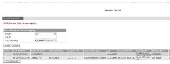
text_image
IP/Ethernet Unit License Query ID Type: 100 Unit ID: Transaction Key: F082035004761500264 Search | Cancel Order Number | Result Member | Install Date | License Name | Transaction Key | Link | Destination Name | Transaction Type | Request Date | 1 | NCEK 0046C AC | NC0046C.CN | 10000000000000000000000000000000000000000000000000000000000000000000000000000000000000000000000 2 | 88.46. CER. 394-ACV | U82222222222222222222222222222222222222222222222222222222222222222222222222222222222222222222222222222 Result to Result NCEK 3946C AC | NC0046C.CN | 1000000000000000000000 | 1001633333333333333333333333333333333333333333333333333333333333333In this example, the line items for Level 1 display hardware-related information and the line items for Level 2 display software-related information. If the query was performed before the transaction key was generated, the first row (Level 1) would not appear as part of the search results. Similarly, if the query was performed before the license was generated, some of the information in the second row would not be displayed.
Transferring a license
A license can be transferred between Dell PowerConnect devices if the following conditions are true:
• The device is under an active support contract, and
- The license is being transferred between two like-models (e.g., from a 24-port model to another 24-port model or from a 48-port model to another 48-port model).
Contact your Dell representative for more information.
TABLE 18 Syslog messages
| Message level Message Explanation | ||
| Warning License: Packagewith LIDdays | with LIDexpires in | The trial license is about to expire. This message will begin to display 3 days before the expiration date, and every 2 hours on the last day that the license will expire. |
| Notification | License: Packagewith LIDhas expired | The trial license has expired. |
Viewing information about software licenses
This section describes the show commands associated with software licensing. These commands are issued on the Dell PowerConnect device, at any level of the CLI.
NOTE
You can also view information about software licenses from the Brocade software portal. Refer to "Viewing software license information" on page 89.
Viewing the License ID (LID)
Dell PowerConnect devices that ship during and after the release of software licensing will have the LID imprinted on the label affixed to the device. You also can use the CLI command show version to view the LID on these devices, and on devices that shipped before the release of software licensing.
Use the show version command to display the serial number, license, and LID of the device. The following is example output from an PowerConnect B-Series FCX unit with the license FCX-ADV-LIC-SW installed.
PowerConnectshow version
Copyright (c) 1996-2010 Brocade Communications Systems, Inc.
UNIT 1: compiled on May 30, 2010 + 16, 20, 20. Ischaled se #778070001
Viewing the license database
To display general information about all software licenses in the license database, use the show license command. The following shows example output.
PowerConnect+show license
| Index | Package Name | Lid | Status | License Type | License Period |
| 1 | PCX624-ADV-LIC-SW | egut-cd05 | active | normal | unlimited |
| 2 | PCX624-ADV-LIC-SW | egut-cd05 | valid | normal | unlimited |
To display detailed information about a particular license, use the show license
PowerConnect#show license 1
Syntax: show license [
The following table describes the information displayed by the show license command.
TABLE 19 Output from the show license command
| This field... Displays... |
| Index The license hash number that uniquely identifies the license. |
| Package Name The package name for the license. |
| Lid The license ID. This number is embedded in the Dell PowerConnect device. |
Status Indicates the status of the license:
- Valid - A license is valid if the LID matches the serial number of the device for which the license was purchased, and the package name is recognized by the system.
- Invalid – The LID does not match the serial number of the device for which the license was purchased.
• Active - The license is valid and in effect on the device.
Viewing software packages installed in the device
Use the show version command to view the software packages that are currently installed in the
device.
NOTE
The software package name is not the same as the license name.
PowerConnect↓show version
Copyright (c) 1996-2010 Brocade Communications Systems, Inc.
UNIT 1: compiled on Mar 30 2010 at 18:39:20 labeled as FCXR07000bl
(5245400 bytes) from Secondary FCXR07000bl.bin
SW: Version 07.0.00B17f3
Boot-Monitor Image size = 369286, Version:07.0.01T7f5 {grz07001}
SW: Stackable FCX624SF
UNIT 1: SL 1: FCX-24GS 24-port Management Module
Serial #: PR320400289
license: FCX_adv_router_soft_package (lid: rlihfjffhna)
P-ENGINE 0: type DB10, rev 01
UNIT 1: SL 2: FCX-2XGC 2-port 16G Module {2-CX4}
800 MHz Power PC processor 8544E (version 33/0022) 400 MHz bus 65536 KB flash memory
256 MB DRAM
Monitor Option is on
STACKID 1 system uptime is 16 hours 35 minutes 25 seconds
The system : started=warm start reloaded=by "reload"
Table 20 lists the supported software packages.
TABLE 20 Software packages
Product Software package name License needed?
PowerConnect B-Series BASE_SOFT_PACKAGE No
FCX
EVY FULL ROUTER COST PACKAGE No
Table 21 lists the individual Dell PowerConnect switches and the Ironstack features they support.
TABLE 21 Supported Ironstack features
| Feature | PowerConnect B-Series FCX ^1 |
| Building an IronStackSecure setupAutomatic configurationManual configuration | Yes |
| Ironstack management | Yes |
| Ironstack management MAC address | Yes |
| Ironstack partitioning | Yes |
| Persistent MAC address | Yes |
| Ironstack software upgrade | Yes |
| Ironstack and stack mismatch troubleshooting | Yes |
| Hitless stacking:Hitless failoverHitless switchover | Yes |
- All PowerConnect B-Series FCX models can be ordered from the factory as -ADV models. ADV models include support for Layer 3 BGP. PowerConnect B-Series FCX-E and PowerConnect B-Series FCX-I models require an optional 10 Gbps SFP+ module to support stacking.
• Active Controller, Standby Controller, and member units in a stack
• Active Controller management of entire stack
• Active Controller download of software images to all stack units
- Standby Controller for stack redundancy
• Active Controller maintenance of information database for all stack units
- Packet switching in hardware between ports on stack units
- All protocols operate on an IronStack in the same way as on a chassis system.
Stackable models
PowerConnect B-Series FCX devices
All PowerConnect B-Series FCXdevices can be active members of a IronStack. PowerConnect B-Series FCX-E and PowerConnect B-Series FCX-I models require an optional 10 Gbps SFP+ module to support stacking. For information about how to install PowerConnect B-Series FCX devices, see the PowerConnect B-FCX Switch Hardware Installation Guide.
All PowerConnect B-Series FCX devices can be ordered from the factory as -ADV models with support for Layer 3 BGP.
IronStack terminology
Stack unit roles:
- Active Controller - Handles stack management and configures all system- and interface-level features.
- Future Active Controller - The unit that will take over as Active Controller after the next reload, if its priority has been changed to the highest priority. When a priority for a stack unit is changed to be higher than the existing Active Controller, the takeover does not happen immediately to prevent disruptions in the stack operation.
show, stack, and a few debug commands. When the stack is formed, all local consoles are directed to the Active Controller, which can access the entire CLI. The last line of output from the show version command indicates the role of a unit, unless it is a standalone unit, in which case it is not shown. For example:
My stack unit ID = 1, boctup role = active
- Clean Unit - A unit that contains no startup flash configuration or run time configuration. To erase old configuration information, enter the erase startup-config command and reset the unit. For PowerConnect B-Series FCX devices, the run-time configuration on a clean unit may also contain default-port information,
- Control Path - A path across stacking links dedicated to carrying control traffic such as commands to program hardware or software image data for upgrades. A stack unit must join the control path to operate fully in the stack.
- Default Port - PowerConnect B-Series FCX devices use the default-port command to define stacking port candidates.
- Interprocessor Communications (IPC) - The process by which proprietary packets are exchanged between stack unit CPUs.
- IronStack - A set of stackable units (maximum of eight) and their connected stacking links so that: all units can be accessed through their common connections, a single unit can manage the entire stack, and configurable entities, such as VLANs and trunk groups, can have members on multiple stack units.
- Non-Functioning Stack Unit - A stack unit that is recognized as a stack member, and is communicating with the Active Controller over the Control Path, but is in a non-functioning state. Because of this state, traffic from the non-stack ports will not be forwarded into the stack - they will be dropped or discarded. This may be caused by an image or configuration mismatch.
- Sequential Connection - Stack unit IDs, beginning with the Active Controller, are sequential. For example, 1, 3, 4, 6, 7 is sequential if Active Controller is 1, 1, 7, 6, 4, 3 are non-sequential in a linear topology, but become sequential in a ring topology when counted from the other direction as: 1, 3, 4, 6, 7. Gaps in numbering are allowed.
-
Standalone Unit - A unit that is not enabled for stacking, or an Active Controller without any Standby Controller or stack members.
-
Static Configuration - A configuration that remains in the database of the Active Controller even if the unit it refers to is removed from the stack. Static configurations are derived from the startup configuration file during the boot sequence, are manually entered, or are converted from dynamic configurations after a write memory command is issued.
- Dynamic Configuration - A unit configuration that is dynamically learned by a new stack unit from the Active Controller. A dynamic configuration disappears when the unit leaves the stack.
Building an IronStack
This section describes how to build an IronStack. Before you begin, you should be familiar with the supported stack topologies and the software requirements. When you are ready to build your stack, you can go directly to the instructions.
IronStack topologies
IronStack technology supports linear and ring stack topologies. Although stackable units may be connected in a simple linear topology, Dell recommends a ring topology because it offers the best redundancy and the most resilient operation.
Mixed unit topologies
For more information about PowerConnect B-Series FCX stack topologies, see "PowerConnect B-Series FCX stack topologies" on page 98.
PowerConnect B-Series FCX stack topologies
A IronStack can contain all one model, or any combination of the PowerConnect B-Series FCX models. You can mix 24-port and 48-port FCX devices in a single stack, to a maximum of eight units per stack.
The procedure for cabling a stack of PowerConnect B-Series FCX devices differs depending on whether your stack contains PowerConnect B-Series FCX-E and PowerConnect B-Series FCX-I
FIGURE 11 PowerConnect B-Series FCX linear and ring stack topologies
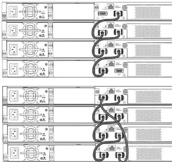
text_image
Diagram showing rack-mounted server racks with connected cables and ports, including labeled connectors and switchesFIGURE 13 PowerConnect B-FCX-E linear topology stack using SFP+ module ports

natural_image
Front view diagram of a network device rack with multiple ports and connectors (no text or labels visible)FIGURE 14 Mixed linear stack of PowerConnect B-FCX-E devices and PowerConnect B-FCX-S devices

text_image
Diagram of a network topology showing multiple Ethernet switches connected to a rack-mounted interface with labeled ports and cables.- Use the secure-setup utility to form your stack. Secure-setup gives you control over the design of your stack topology and provides security through password verification. For the secure-setup procedure, refer to "Scenario 1 - Configuring a three-member IronStack in a ring topology using secure-setup" on page 101.
- Automatic stack configuration. With this method, you enter all configuration information, including the module type and the priorities of all members into the unit you decide will be the Active Controller and set its priority to be the highest. When you enable stacking on the Active Controller the stack then forms automatically. This method requires that you start with clean units (except for the Active Controller) that do not contain startup or run time configurations. Refer to "Scenario 2 - Configuring a three-member IronStack in a ring topology using the automatic setup process" on page 105.
- Manual stack configuration. With this method, you configure every unit individually, and enable stacking on each unit. Once the units are connected together, they will automatically operate as an IronStack. With this method the unit with the highest priority becomes the Active Controller, and ID assignment is determined by the sequence in which you physically connect the units. Refer to "Scenario 3 - Configuring a three-member IronStack in a ring topology using the manual configuration process" on page 108.
Configuration notes
Before you configure your IronStack, consider the following guidelines:
- Consider the number of units, and the mix of units your stack will contain, and how the stacking ports on the units will be connected. For more information about PowerConnect B-Series FCX devices, refer to the PowerConnect B-FCX Switch Hardware Installation Guide.
- The stack should be physically cabled in a linear or ring topology. Connect only those units that will be active in the stack.
- When you have a full stack of 8 units, you may need to increase the trap hold time from the default, which is 60 seconds, to five minutes (300 seconds). This will prevent the loss of initial boot traps. To increase the trap hold time, use the following command.
PowerConnect# snmp-server enable traps hold 300
Syntax: snmp-server enable traps hold
- Authentication of secure-setup packets provides verification that these packets are from genuine Dell stack unit. MD5-based port verification confirms stacking ports.
- Superuser password is required to allow password-protected devices to become members of an IronStack.
- The stack disable command. When this command is issued, a unit does not listen for or send stacking packets, which means that no other device in the network can force the stacking-disabled unit to join an IronStack.
Secure-setup can also be used to add units to an existing IronStack (refer to "Adding, removing, or replacing units in an IronStack" on page 147) and to change the stack IDs of stack members (refer to "IronStack unit identification" on page 122).
When secure-setup is issued on a unit that is not already the Active Controller, this unit becomes the Active Controller, and, if it does not have an assigned priority, secure-setup assigns it a priority of 128. Any unit that then tries to join the stack must have an assigned priority less than 128. If secure-setup discovers a unit with a priority of 128 or higher, it changes the priority to 118.
When secure-setup is issued on a unit that is not already the Active Controller, this unit becomes the Active Controller. If this unit does not already have an assigned priority, secure-setup will assign this unit a priority of 128 by default, if no other units in the stack have a priority higher than 128. If another unit in the stack has a priority of 128 or higher, secure-setup will give the Active Controller a priority equal to the highest priority unit in the stack (which is by default the Standby Controller). When the Active Controller and the Standby Controller have identical priorities, during a reset, the old Active Controller cannot reassume its role from the Standby Controller (which has become the Active Controller at the reset).
If the previous Active Controller again becomes active, and you want it to resume the role of Active Controller, you should set the priority for the Standby Controller to a priority lower than 128. If you do not want the previous Active Controller to remain Active Controller, you can set the same priority for both Active and Standby Controllers (higher than, or equal to 128). For details, refer to "IronStack unit priority" on page 123.
NOTE
Secure-setup works for units within a single stack. It does not work across stacks.
Follow the steps given below to configure a three-member stack in a ring topology using
- Enter the stack secure-setup command. As shown In the following example, this command triggers a Dell proprietary discovery protocol that begins the discovery process in both upstream and downstream directions. The discovery process produces a list of upstream and downstream devices that are available to join the stack. Secure-setup can detect up to 7 units in each direction (14 total), but since the maximum number of units in a stack is 8, you must select a maximum of 7 units from both directions.
NOTE
To exit the secure-setup, enter ^C at any time.
You should see output similar to the following.
PowerConnect# stack secure-setup
PowerConnect# Discovering the stack topology...
Current Discovered Topology - RING
Available UPSTREAM units
Hop(s) Type Mac Address
1 FCX624 0012.f239.2d40
2 FCX624 0012.f2d5.2100
Available DOWNSTREAM units
Hop(s) Type Mac Address
1 FCX624 0012.f2d5.2100
2 FCX624 0012.f239.2d40
Do you accept the topology (RING) {y/r}?: y
If you accept the topology, you will see output similar to the following.
Selected Topology:
Active Id Type Mac Address
1 FCX648 00e0.52ab.cd00
1 S FCX648 active 00e0.52ab.cd00 128 local Ready
2 D FCX624 standby 0012.f2d5.2100 60 remote Ready
3 D FCX624 member 0012.f239.2d40 0 remote Ready
active standby
+----+
+----+
+----+
-2/1| 1 | 3/1--2/1 | 2 | 3/1--2/2 | 3 | 2/1
+----+
+----+ +----+
Current stack management MAC is 00e0.52ab.cd00
NOTE
For field descriptions for the show stack command, refer to "Displaying stack information" on page 135.
NOTE
In this output, D indicates a dynamic configuration. After you perform a write memory, this display will change to S, for static configuration.
-
The Active Controller automatically checks all prospective stack members to see if they are password protected. If a unit is password protected, you will be asked to enter the password before you can add the unit. If you do not know the password, take one of the following actions:
-
Discontinue secure-setup by entering ^C
- Obtain the device password from the administrator
- Continue secure-setup for your stack. The password-protected device and all devices connected behind it will not be included in the setup process.
In the following example, the second unit is password protected, so you are asked for the password.
PowerConnect# stack secure-setup
PowerConnect# Discovering the stack topology...

Verifying password for the password protected units...
Found UPSTREAM units
- When the Active Controller has finished the authentication process, you will see output that shows the suggested assigned stack IDs for each member. You can accept these recommendations, or you can manually configure stack IDs. Enter the show stack command to verify that all units are in the ready state.
PowerConnect# show stack
alone: standalone, D: dynamic config, S: static config
ID Type Role Mac Address Pri State Comment
1 S FCX624 active 00e0.5201.4000 128 local Ready
2 S FCX648 standby 001b.cd5e.c480 C remote Ready
3 S FCX648 member 00e0.5205.0000 C remote Ready

Current stack management MAC is 00e0.5201.4000
PowerConnect#
NOTE
For field descriptions for the show stack command, refer to "Displaying stack information" on page 135.
- Enter the write memory command on the Active Controller once all of the stack units are active. This command initiates configuration synchronization, which copies the configuration file of the Active Controller to the rest of the stack units.
NOTE
The secure-setup process may modify your configuration with information about new units, stacking ports, etc. For this reason, it is very important to save this information by issuing the write memory command. If you do not do this, you may lose your configuration information the next time the stack reboots.
The secure-setup process for your stack is now complete.
Follow the steps given below to configure a three-member IronStack in a ring topology using automatic setup process.
- Power on the devices.
- This process requires clean devices (except for the Active Controller) that do not contain any configuration information. To change a device to a clean device, enter the erase startup-config command and reset the device. When all of the devices are clean, continue with the next step.
NOTE
The physical connections must be sequential, and must match the stack configuration.
- Log in to the device that you want to be the Active Controller.
- Configure the rest of the units by assigning ID numbers and module information on each unit. The stack ID can be any number from 1 through 8.
PowerConnect# config t
PowerConnect(config)#stack unit 2
PowerConnect{config-unit-2}# module 1 FCX-24-port-management-module
PowerConnect{config-unit-2}# module 2 FCX-xfp-l-port-16g-module
PowerConnect{config-unit-2}# module 3 FCX-xfp-1-port-16g-module
PowerConnect{config-unit-2}# stack unit 3
PowerConnect{config-unit-3}# module 1 FCX-24-port-management-module
PowerConnect{config-unit-3}# module 2 FCX-xfp-1-port-16q-module
PowerConnect{config-unit-3}# module 3 FCX-xfp-l-port-16g-module
NOTE
Each stack unit must have a unique ID number.
- Assign a priority to the Active Controller using the priority command, as shown.
PowerConnect(config)‡ stack unit 1
PowerConnect(config-stack-1) priority 255
Syntax: priority
-
- Assign a priority to the unit that will act as Standby Controller.
PowerConnect show running config
Current configuration:
!
vor 07.2.00a
!
stack unit 1
module 1 FCX-24-port-management-module
priority 255
stack unit 2
module 1 FCX-24-port-management-module
priority 240
stack unit 3
module 1 FCX-24-port-management-module
stack enable
!
NOTE
For field descriptions for the show running config command, refer to "Displaying running configuration information" on page 143.
- To see information about your stack, enter the show stack command.
PowerConnect# show stack
alone: standalone, D: dynamic config, S: static config
ID Type Role Mac Address Pri State Comment
1 S FCX624 active 00e0.5200.0100 255 local Ready
2 S FCX624 standby 0012.f2eb.afc0 240 remote Ready
5 S FCX624 member 0UIb.ed5a.alcu U remote Ready

Current stack management MAC is 00e0.5200.0100
PowerConnect#
Scenario 3 - Configuring a three-member IronStack in a ring topology using the manual configuration process
NOTE
For more detailed information about configuring an PowerConnect B-Series FCX IronStack, see "Configuring an FCX IronStack" on page 109
Follow the steps given below to configure a three-member IronStack in a ring topology using the manual configuration process.
- Power on the devices. Do not connect the stacking cables at this point.
- Assign a priority of 255 to unit 1, and a priority of 240 to unit 3 using the priority command. You do not have to assign a priority to the third device. Enter the stack enable command on each device. In this example, device 1 will be the Active Controller and device 2 will be the Standby Controller.
Unit 1
PowerConnect# config t
PowerConnect(config)# stack unit 1
PowerConnect{config-unit-1}# priority 255
PowerConnect{config-unit-1}# stack enable
Enable stacking. This unit actively participates in stacking
PowerConnect{config-unit-1}# write memory
Write startup-config done.
PowerConnect(config-unit-1)# Flash Memory Write (8192 bytes per dot) .Flash to Flash Done.
PowerConnect(config-unit-1) # end
Unit 2
PowerConnect# config t
PowerConnectconfig† stack enable
Enable stacking. This unit actively participates in stacking
PowerConnect(config)# Handle election, was standalone --> member,
assigned-ID=2, T=261285 ms.
For more information about cabling the devices, refer to the appropriate hardware installation guides.
NOTE
This method does not guarantee sequential stack IDs. If you want to change stack IDs to make them sequential, you can use secure-setup. Refer to "Renumbering stack units" on page 149.
Configuring an FCX IronStack
Every PowerConnect B-Series FCX-S device contains two default 16 Gbps stacking ports on the rear panel and two 10 Gbps ports on the front panel that can also be used as stacking ports.
NOTE
PowerConnect B-Series FCX-I and PowerConnect B-Series FCX-E devices can only be used for stacking if they have an optional 10 Gbps SFP+ module installed in the front panel. These devices do not have stacking ports on the rear panels.
An PowerConnect B-Series FCX IronStack may contain up to eight 24-port and 48-port devices, using any combination of the rear panel stacking ports and the front panel optional stacking ports. For PowerConnect B-Series FCXs devices, to use ports other than the factory-default 16 Gbps ports, you must define the ports for each device in the run time configuration. You can also configure the 16 Gbps ports to operate as 10 Gbps ports. See "Configuring PowerConnect B-Series FCX stacking ports" on page 109.
An PowerConnect B-Series FCX "clean unit" may contain a default port configuration, but it is still considered a clean unit. To preserve this state, do not do a write memory on the unit before you build the stack. An PowerConnect B-Series FCX device with the default port configuration is still considered a clean unit. To ensure that the device remains a clean unit, do not do a write memory on the device. (Write memory adds a startup-config, and the device is no longer a clean unit.)
NOTE
The automatic setup process will not work for PowerConnect B-Series FCX devices that do not contain the default port information in their clean unit configurations.
NOTE
If you are adding PowerConnect B-Series FCX-E or PowerConnect B-Series FCX-I devices to a stack containing PowerConnect B-Series FCX-S devices, you must reconfigure the stacking ports on the PowerConnect B-Series FCX-S devices to be the 10 Gbps ports on the front panel. You can then connect all of the devices in a stack using front panel ports.
Changing PowerConnect B-Series FCX-S and CX4 ports from 16 Gbps to 10 Gbps
You can configure the 16 Gbps PowerConnect B-Series FCX4 ports to operate as 10 Gbps ports using the speed-duplex command, as shown in the following example.
Syntax: speed-duplex [10-full | 10-half | 100-full | 100-half | 1000-full-master | 1000-full-slave | 10g-full | auto]
• 10-full - 10M, full duplex
• 10-half - 10M, half duplex
• 100-full - 100M, full duplex
• 100-half - 100M, half duplex
• 1000-full-master - 1G, full duplex, master
• 1000-full-slave - 1G, full duplex, slave
• 10g-full - 10G, full duplex
• auto - Autonegotiation
NOTE
Both ends of a link must be configured for 10 Gbps for the link to operate as 10 Gbps. If you want the link to operate as a 16 Gbps link, both ends of the link must be configured for 16 Gbps.
| PowerConnect(config-if-e10000-cx4-1/2/1)† speed-duplex 10g-full | ||||||||
| PowerConnect(config-if-e10000-cx4-1/2/1)‡ end | ||||||||
| PowerConnect# show int br | in Up | ||||||||
| 1/1/4 | Up | Forward | Full 1G | None | No | 1 | 0 | 001b.f288.0003 |
| 1/2/1 | Up | forward | Full 10G | None | No | 1 | 0 | 001b.f288.0019 |
| 1/3/1 | Up | Forward | Full 10G | None | No | N/A | 0 | 001b.f288.001b |
| 3/3/1 | Up | Forward | Full 10G | None | No | N/A | 0 | 0024.3814.9df3 |
| mometl | Up | None | Full 1G | None | No | 1 | 0 | 001b.f288.0018 |
0 runts, 0 giants
0 packets output, 0 bytes, 0 underruns
Transmitted 0 broadcasts, 0 multicasts, 0 unicasts
0 output errors, 0 collisions
Relay Agent Information option: Disabled
Changing PowerConnect B-Series FCX-S and PowerConnect B-Series FCXS-PowerConnect B-Series FCX4 ports from 10 Gbps to 16 Gbps
To change the PowerConnect B-Series FCX4 ports from 10 Gbps back to 16 Gbps, enter the no speed-duplex 10g command at the interface level of the CLI, as shown in this example.
PowerConnect(config-if-e10000-cx4-1/2/1)† no speed-duplex 10g
PowerConnect(config-if-e10000-cx4-1/2/1)↓ show interface br | in Up
1/1/4 Up Forward Full 1G None No 1 0 001b.f286.0003
1/2/1 Up Forward Full 16G None No 1 0 001b.f288.0019
1/3/1 Up Forward Full 10G None No N/A 0 001b.f288.001b
3/3/1 Up Forward Full 10G None No N/A 0 0024.3814.Sdf3
mgmt.1 Up None Full 1G None No 1 0 001b.f288.0018
PowerConnect(config-if-e10000-cx4-1/2/1)† show interface e 1/2/1
16GigabitEthernet1/2/1 is up, line protocol is up
Hardware is 16CigabitEthernet, address is 00lb.f288.0019 (bia 00lb.f288.0019)
Interface type is 16Gig CX4
Member of L2 VLAN ID 1, port is untagged, port state is FORWARDING
BPDU guard is Disabled, ROOT protect is Disabled
Link Error Dampening is Disabled
STP configured to ON, priority is level0, mac-learning is enabled
Flow Control is enabled
mirror disabled, monitor disabled
Not member of any active trunks
Not member of any configured trunks
No port nam
IP MTU 1500 bytes, encapsulation ethernet
300 second input rate: 0 bits/sec, 0 packets/sec, 0.00% utilization
300 second output rate: 0 bits/sec, 0 packets/sec, 0.00% utilization
0 packets input, 0 bytes, 0 no buffer
Received 0 broadcasts, 0 multicasts, 0 unicasts
Secure-setup probe packets can be received by a default port whether or not it is acting as a stacking port. Stacking packets can be only received by a stacking port (which is also always a default port). In order to use stacking ports that are not defined in the default configuration, you must define the port settings for each unit using the default-port command, so that secure-setup can discover the topology of the stack.
The 4-byte Ethernet preamble for the Ethernet frame is used when a port is configured as a default stacking port. For non-default ports, the standard 8-byte Ethernet preamble is used. For a default port that is used as a regular data port, the standard 8-byte Ethernet preamble must be explicitly enabled on the port using the longpreamble command. For details, refer to "Configuring a default stacking port to function as a data port" on page 115.
Stackable devices ship with two default stacking ports configured. Use the stack-port command to select only one of these factory default ports as the stacking port. If you do not configure stack-port, both default ports will operate as stacking ports.
Use the default-port command to use ports other than the factory default ports as stacking ports. You must configure default-port on each unit before building a stack. Once you have configured default-port on all units, you can then use any of the three stack construction methods to build a stack. The Active Controller then learns the port configuration for each unit.
NOTE
You cannot change the setting for a default port if the port is in use.
Changing default stacking port configurations
For PowerConnect B-Series FCX-E and PowerConnect B-Series FCX-I devices, ports 1 and 2 of the optional 10 Gbps SFP+ module (slot 2) act as the default stacking ports. You can change the default stacking ports to 3 and 4 on this module, or disable stacking, on all of the module ports. The following example changes the default ports on a 10 Gbps module from 1 and 2 to 3 and 4.
PowerConnect 10g-1(config)# stack unit 1
10g-1{config-unit-1}#
10g-1{config-unit-1}# default-ports 1/2/3 - 1/2/4
Table 22 identifies the slot and port designations for each model.
TABLE 22 Slot and port designations for PowerConnect stackable devices
| Device Slot 1 Slot 2 Slot 3 Slot 4 | ||||
| PowerConnect B-Series FCX624S | 24 10/100/1000 ports on front panel | Two 16 Gbps ports on rear panel | Two 10 Gbps ports on front panel | N/A |
| PowerConnect B-Series FCX648S | 48 10/100/1000 ports on front panel | Two 16 Gbps ports on rear panel | Two 10 Gbps ports on front panel | N/A |
| PowerConnect B-Series FCX-E devices with four-port 1 Gbps SFP module | Four-port 1 Gbps SFP module plus the first four copper ports act as a combo port. Slot 1 also contains the remaining 20 10/100/1000 ports. | N/A N/A N/A | ||
| PowerConnect B-Series FCX-I devices with four-port 1 Gbps SFP module | Four-port 1 Gbps SFP module plus the first four copper ports act as a combo port. Slot 1 also contains the remaining 20 10/100/1000 ports. | N/A N/A N/A | ||
| PowerConnect B-Series FCX-E devices with four-port 10 Gbps SFP+ module | 48 10/100/1000 ports on front panel | Four-port 10 Gbps SFP+ module (supports stacking) | N/A N/A | |
| PowerConnect B-Series FCX-I devices with four-port 10 Gbps SFP+ module | 48 10/100/1000 ports on front panel | Four-port 10 Gbps SFP+ module (supports stacking) | N/A N/A | |
NOTE
If you enter an incorrect stack port number, you will get an error similar to the following.
PowerConnectconfig-unit-3)# stack-port 3/4/1
Error! port 3/4/1 is invalid
PowerConnect(config-unit-3)# stack-port 3/2/1
To return both ports to stacking status, enter the no stack-port command on the single stacking port. This converts both ports to stacking ports. By default, if both ports are stacking ports, they are displayed by the system only when stacking is enabled. If only one port is configured as a stacking port, the system always displays this port.
Using secure-setup to build an FCX IronStack
You can use the secure-setup utility to build an PowerConnect B-Series FCX IronStack by performing the following steps.
- When you have designated the desired stacking ports and connected your PowerConnect B-Series FCX units together, on stack unit 1, enter stack enable and stack secure-setup, as shown.
PowerConnect# stack enable
PowerConnect# stack secure-setup
PowerConnect‡ Discovering the stack topology...
Available UPSTREAM units
Hop(s) Id Type Mac Address
1 new FCX648 0012.f2d6.0511
2 new FCX624 0200.9999.0000
Enter the number of the desired UPSTREAM units (0-2) [0]: 2
Selected Topology:
Active Id Type Mac Address
1 FCX624 001b.f2e5.0100
Selected UPSTREAM units
Hop(s) Id Type Mac Address
1 2 FCX648 0012.f2d6.0511
2 3 FCX624 0200.9999.0000
Stack unit 3 Power supply 1 is up
Stack unit 3 Power supply 2 is down
Config changed due to add/dol units. Do write mom if you want to keep it Election, was active, no role change, assigned-ID=1, total 3 units, my priority=128
PowerConnect
Config changed due to add/del units. Do write mem if you want to keep it
PowerConnect# show stack
alone: standalone, D: dynamic config, S: static config
ID Type Role Mac Address Pri State Comment
1 S FCX624 active 001b.f2e5.0100 128 local Ready
2 D FCX648 standby 0012.f2d6.0511 0 remote Ready
3 D FCX624 member 0200.9999.0000 0 remote Ready
| standby | active | |
| +----+ | +----+ | +----+ |
| | 3 | 3/1--3/1 | 2 | 2/1--2/1 | 1 | | ||
| +----+ | +----+ | +----+ |
Current stack management MAC is 001b.f2e5.0100
PowerConnect# write mem
Write startup-config done.
PowerConnect# Flash Memory Write (8192 bytes per dot) .Flash to Flash Done.
PowerConnect#show stack
alone: standalone, D: dynamic config, S: static config
ID Type Role Mac Address Pri State Comment
1 S FCX624 active 001b.f2e5.0100 128 local Ready
2 S FCX648 standby 0012.f2de.0511 C remote Ready
3 S FCX624 member 0200.9999.0000 0 remote Ready
| standby | active | |
| +----+ | +----+ | +----+ |
| | 3 \ +----+ | | | 3/1--3/1 \ +----+ | | | 2/1--2/1 \ +----+ | |
Use the no form of the command to revert to the 4-byte Ethernet preamble.
Verifying an IronStack configuration
Verifying an PowerConnect B-Series FCX IronStack configuration
The following output shows an example configuration of an PowerConnect B-Series FCX IronStack.
PowerConnect# show stack
alone: standalone, D: dynamic config, S: static config
ID Type Role Mac Address Pri State Comment
2 S FCX648 standby 00e0.5202.0000 C remote Ready
3 S FCX624 member 00e0.5203.0000 C remote Ready
4 S FCX648 member 00e0.5204.0000 C remote Ready
5 S FCX648 member 00e0.0000.0000 C remoteReady
6 S FCX648 active 00e0.5201.0000 128 local Ready
active standby
+---- +---- +---- +----
-2/1 | 8 | 2/2--2/1 | 4 | 2/2--2/1 | 3 | 2/2--2/1 | 2 | 2/2-
+---- +---- +---- +---- |
----
Current stack management MAC is 00e0.5201.0000
The next example shows output from the show version command for the same FCX stack.
PowerConnect# show version
Copyright (c) 1936-2009 Brocade Communications Systems, Inc.
UNIT 8: compiled on Jun 17 2009 at 06:23:29 labeled as FCX06000a359
(3578117 bytes) from Primary FCX06000a359.bin
SW: Version 7.2.0a
UNIT 2: compiled on Jun 17 2009 at 06:23:29 labeled as FCX06000a359
(3578117 bytes) from Primary FCX06000a359.bin
SW: Version 7.2.0a
UNIT 3: compiled on Jun 17 2009 at 06:23:29 labeled as FCX06000a359
(3578117 bytes) from Primary FCX06000a359.bin
SW: Version 7.2.0a
UNIT 4: compiled on Jun 17 2009 at 06:23:29 labeled as FCX06000a359
P-ENGINE 1: type DB90, rev 01
UNIT 4: SL 2: FCX-2XGC 2-port 16G Module (2-CX4)
UNIT 4: SL 3: FCX-2XG 2-port 16G Module (2-XFP)
UNIT 8: SL 1: FCX-45G 43-port Management Module
P-ENGINE 0: Type DB90, rev 01
P-ENCINE 1: type DB90, rev 01
UNIT 8: SL 2: FCX-2XGC 2-port 16G Module (2-CX4)
800 MHz Power PC processor (version 33/0022) 144 MHz bus
65536 KB flash memory
256 MG DRAM
Monitor Option is on
STACKID 8 system uptime is 21 hours 2 minutes 23 seconds
STACKID 2 system uptime is 21 hours 2 minutes 22 seconds
STACKID 3 system uptime is 21 hours 2 minutes 23 seconds
STACKID 4 system uptime is 21 hours 2 minutes 22 seconds
The system : started=warm start reloaded=by "reload"
My stack unit ID - 8, bootup role - active
*** NOT FOR PRODUCTION ***
NOTE
For field descriptions for the show running config command, refer to "Displaying running configuration information" on page 143.
NOTE
For field descriptions for the show stack and show stack detail commands, refer to “Displaying stack information” on page 135.
The output from the show stack command contains a visual diagram of the stack. The dashed line between ports 1/2/1 and 3/2/1 indicates that this stack is configured in a ring topology. If the link between ports 1/2/1 and 3/2/1 is lost, the stack topology changes to linear, and the diagram changes to resemble the following.
active standby
Managing your IronStack
Your IronStack can be managed through a single IP address. You can manage the stack using this IP address even if you remove the Active Controller or any member from the stack. You can also connect to the Active Controller through Telnet or SSH using this address. All management functions, such as SNMP, use this IP address to acquire MIB information and other management data.
A Dell IronStack can be configured and managed using the command line interface (CLI) over a serial connection to a console port, or using Brocade Network Advisor. To determine what version of Brocade Network Advisor supports IronStack refer to the Brocade Network Advisor User Guide.
Logging in through the CLI
You can access the IronStack and the CLI in two ways:
• Through a direct serial connection to the console port
- Through a local or remote Telnet session using the stack IP address
You can initiate a local Telnet or SNMP connection by attaching a cable to a port and specifying the assigned management station IP address.
The stacking commands in the CLI are organized into the following levels:
- Global – Commands issued in the global mode are applied to the entire stack.
- Stack Member Configuration Mode – Commands issued in this mode apply to the specified stack member. Configuration information resides in the Active Controller.
- Configuration Mode - This is where you make configuration changes to the unit. To save changes across reloads, you need to save them to the Active Controller startup-config file. The configuration mode contains sub-levels for individual ports, for VLANs, for routing protocols, and other configuration areas.
NOTE
By default, any user who can open a serial or Telnet connection to the IronStack can access all of these CLI levels. To secure access, you can configure Enable passwords or local user accounts, or
on the Active Controller physical console port during a reload will not be visible on the console ports of the stack members because the remote connections are not established until the software loading process is complete. It is preferable to connect a cable to the console port on the stack unit that will normally be the Active Controller, rather than to the console port of one of the other stack units.
When a stack unit establishes communication with the Active Controller, it also establishes a remote console session to the Active Controller. In a normally functioning IronStack, a console cable may be connected to any of the stack units and provide access to the same commands on the Active Controller.
You can terminate a session by entering Ctrl+O followed by 'x' or 'X', or by entering the 'exit' command from the User EXEC level, or by entering the 'logout' command at any level.
NOTE
For the rconsole connections from the stack units to the Active Controller, the escape sequence and other methods of terminating the session are not available.
NOTE
Error messages that are generated during a reload of the Active Controller will not appear on rconsole connections from the stack units to the Active Controller. To see these error messages, you must connect a console cable to the Active Controller itself.
To establish an rconsole session, enter the rconsole command as shown:
PowerConnect# rconsole 1
Syntax: rconsole
The following example shows how to establish rconsole sessions to stack members. Notice that the show stack command on the stack members displays different information than what is shown when the show stack command is entered on the Active Controller.
To see the status of your stack units, enter the show stack command on the Active Controller.
PowerConnect# show stack
alone: standalone, D: dynamic config, S: static config
ID Type Role Mac Address Pri State Comment
PowerConnect rconsole 2
Connecting to unit 2... (Press Ctrl-O X to exit)
rcconsole-2@PowerConnect#show stack
ID Type Role Mac Address Prio State Comment
2 S FCX624P standby 0012.f2e2.ba40 0 local Ready
rconsole-20PowerConnect# exit
rconsole-2@PowerConnect> exit.
Disconnected. Returning to local session...
Establish a remote console session with stack unit 3.
PowerConnect# rconsole 3
Connecting to unit 3... (Press Ctrl-O X to exit)
rconsole-3@PowerConnect# show stack
ID Type Role Mac Address Prio State Comment
3 S FCX624F member 001b,ed7a,22c0 0 local Ready
rcansale-3@PowerConnect# 1ogout
Disconnected. Returning to local session...
PowerConnect#
IronStack management MAC address
The IronStack is identified in the network by a single MAC address, usually the MAC address of the Active Controller (the default). If a new Active Controller is elected, the MAC address of the new Active Controller (by default) becomes the MAC address for the entire stack. However, you can manually configure your stack to use a specified MAC address. Refer to "Manual allocation of the IronStack MAC address" on page 120.
In an IronStack, the management MAC address is generated by the software, and is always the MAC address of the first port of the Active Controller. This ensures that the management MAC address remains consistent across stack reboots, and helps prevent frequent topology changes as a result of protocol enable, disable, and configuration changes.
When you are configuring Layer 2 protocols on stack units, such as STP, RSTP, and MSTP, the management MAC address of the Active Controller acts as the Bridge ID.
NOTE
For hitless stacking failover, Dell recommends that you configure the IronStack MAC address using the stack mac command. Without this configuration, the MAC address of the stack will change to the new base MAC address of the Active Controller. This could cause a spanning tree root change. Even without a spanning tree change, a client (for example, a personal computer) pinging the stack might encounter a long delay depending on the client MAC aging time. The client won't work until it ages out the old MAC address and sends ARP requests to relearn the new stack MAC address.
To configure a stack MAC address manually, enter the following command.
PowerConnect(config)# stack mac 0000.0000.0011
Syntax: [no] stack mac
mac-address - a hexadecimal MAC address in the xxxx.xxxx.xxxx format
Enter the no form of this command to return the MAC address to that of the Active Controller.
Output for this command resembles the following.
PowerConnect(config)# stack mac 0000.0000.0011
PowerConnect(config)# show running-config
Current configuration:
ver 7.2.00a 100T7cl
!
stock
module 1 FCX-48-port-management-module
module 2 FCX-cx4-2-port-16q-module
priority 80
stack 2
module 1 FCX-24-port-management-module
module 2 FCX-cx4-2-port-16g-module
module 3 FCX-cx4-2-port-16g-module
stack enable
stack mac 0000.0000.0011
To display the stack MAC address, enter the show chassis command.
PowerConnect# show chassis
Fan 1 ok
Fan 2. ok --More--, next page; Space, next line; Return key, quit: Control-c
NOTE
For field descriptions for the show chassis command, refer to "Displaying chassis information" on page 133.
Removing MAC address entries
You can remove the following types of learned MAC address entries from the Dell system MAC address table:
- All MAC address entries
• All MAC address entries for a specified Ethernet port
• All MAC address entries for a specified VLAN
• A specified MAC address entry in all VLANs
For example, to remove entries for the MAC address 000d.cb80.00d in all VLANs, enter the following command at the Privileged EXEC level of the CLI.
PowerConnect# clear mac-address 000d.cb80.00d0
Syntax: clear mac-address
- If you enter the clear mac-address command without any parameters, the software removes all MAC entries.
- Use the
parameter to remove a specified MAC address from all VLANs. Specify the MAC address in the following format: HHHH.HHHH.HHHH. - Use the ethernet
parameter to remove all MAC addresses for a specified Ethernet port. Specify the variable in the format . - Use the vlan
parameter to remove all MAC addresses for a specified VLAN.
IronStack unit priority
A unit with a higher priority is more likely to be elected Active Controller. The priority value can be 0 to 255 with a priority of 255 being the highest. The default priority value assigned to the Active Controller and Standby is 128.
You can assign the highest priority value to the stack unit you want to function as the Active Controller. When you enter a new priority value for a stack unit, that value takes effect immediately, but does not affect the current Active Controller until the next reset. For details, refer to “Changing the priority of a stack unit” on page 123.
You can give your Active and Standby Controllers the same priority, or different priorities (Active highest, Standby second-highest). When Active and Standby Controllers have the same priority, if the Active fails and the Standby takes over, then the original Active becomes operational again, it will not be able to resume its original role if the new Active Controller has more members.
NOTE
For two unit stacks, this behavior does not apply. When the Active and Standby Controllers have the same priority, the Active Controller will always resume its original role.
In the same situation, when the priorities of the Active and Standby Controllers are different, the old Active Controller will regain its role and will reset the other units.
For example, suppose both Active and Standby Controllers have the same priority. If there are more than two units in a stack and the Active Controller leaves and comes back, it cannot win back the Active role because the new Active Controller has more members than the old Active Controller, which has no members. If there are only two units in a stack, the old Active Controller may win back the Active role if it has a lower unit ID. In this case, both the old Active Controller and new Active Controller have no members, so the unit with the lower unit ID wins the Active role.
If you want to assign the same priority to the Active and Standby Controllers, you must do so after the stack is formed. This prevents the intended Standby Controller from becoming the Active Controller during stack construction.
Changing the priority of a stack member will trigger an election that takes effect immediately unless the Active Controller role changes. If this is the case, the changes will not take effect until after the next stack reload.
CLI command syntax
CLI syntax that refers to stack units must contain all of the following parameters:
- If the device is operating as a standalone, the stack-unit will be 0 or 1. Stack IDs can be 0 or any number from 1 through 8. - Refers to a specific group of ports on each device. - A valid port number. You can list all of the ports individually, use the keyword to to specify ranges of ports, or a combination of both. To apply the configuration to all ports on the device, use the keyword all in
IronStack CLI commands
CLI commands specific to stacking are listed in Table 23, with a link to the description for each command. For more information about CLI commands and syntax conventions, refer to Chapter 1, "Getting Familiar with Management Applications".
TABLE 23 Stacking CLI commands
| Command Description location... | |
| copy flash flash | "Copying the flash image to a stack unit from the Active Controller" on page 126 |
| clear stack ipc | "Troubleshooting an unsuccessful stack build" on page 152 |
| cx4 10g "Changing PowerConnect B Series FCX S and CX4 ports from 16 Gbps to 10 Gbps" on page 110 | |
| kill console | "Configuring TACACS/TACACS+ for devices in a Dell IronStack" on page 1165 |
| priority | "Changing the priority of a stack unit" on page 123 |
| rconsole | "Logging in through the console port" on page 118 |
| reload stack unit | "Reloading a stack unit" on page 126 |
show chassis
"Displaying chassis information" on page 133
TABLE 23 Stacking CLI commands (Continued)
| Command | Description location... |
| show statistics stack-port | "Displaying stacking port statistics" on page 146 |
| show interfaces stack-ports | "Displaying stacking port interface information" on page 145 |
| show version | "Displaying software version information" on page 144 |
| stack enable "Stacking mode" on page 125 | |
| stack disable "Stacking mode" on page 125 | |
| stack mac [mac-address] | "IronStack management MAC address" on page 120 |
| stack persistent-mac-timer | "Persistent MAC address" on page 128 |
| stack-port | "Changing default stacking port configurations" on page 112 |
| default ports | "Changing default stacking port configurations" on page 112 |
| stack secure-setup | "Scenario 1 - Configuring a three-member IronStack in a ring topology using secure-setup" on page 101 |
| stack unconfigure | "Unconfiguring an IronStack" on page 130 |
| hitless-failover enable | "Enabling hitless stacking" on page 174 |
| stack-switchover | "Executing a hitless stacking switchover" on page 177 |
| debug stacking sync_rel_msg | "Displaying hitloss stacking diagnostic information" on page 184 |
Stacking mode
When a unit is stack-enabled or joins a stack either actively or passively, it reserves priority queue 7 for stacking traffic control, assigns buffers for the stacking ports, and configures the first two 10 Gbps ports as stacking ports.
NOTE
Designated stacking ports cannot contain any configuration information, such as VLAN membership, etc. If configuration information exists, stack enable will fail. You must remove all configuration information from the port and re-issue the stack enable command.
NOTE
The two left ports on the Four-port 10Gbps SFP+ module do not pass regular Ethernet traffic by default. The stack disable command must be entered at the global level and the stack disable command must be configured on these two ports in order for them to pass regular traffic.
Copying the flash image to a stack unit from the Active Controller
To copy the flash image to a stack unit from the Active Controller primary or secondary flash, enter the following command.
PowerConnect# copy flash flash unit-id-pri 2
Syntax: copy flash flash [primary | secondary | unit-id-pri
• primary - Copy secondary to primary
• secondary - Copy primary to secondary
• unit-id-prl - Copy active primary image to unit-id
• unit-id-sec - Copy active secondary image to unit-id
The unit-id-pri or unit-id-sec keywords are used to copy images to a stack member from the Active Controller primary and secondary flash, respectively. For
Reloading a stack unit
To reload a stack unit, enter the following command.
PowerConnect# reload
Syntax: reload [after | at | cancel | unit-id
• after - schedule reloading after certain time period
• at - schedule reloading at an exact later time
Managing your IronStack
Available UPSTREAM units
| Hop (s) | Type | Mac Address |
| 1 | FCX624 | 0012.f2d5.2100 |
| 2 | FCX624 | 001b.cd5d.9940 |
Available DOWNSTREAM units
| Hop (s) | Type | Mac Address |
| 1 | FCX624 | 001b.ed5d.9940 |
| 2 | FCX624 | 0012.f2d5.2100 |
Do you accept the topology (RING) (y/n)?: n
Available UPSTREAM units
| Hop (s) | Type | Mac Address |
| 1 | FCX624 | 0012.r2d5.2100 |
| 2 | FCX624 | 001b.cd5d.9940 |
Available DOWNSTREAM units
Hop (s) Type Mac Address 1 ECX624 001b ed5d SB40
1 FCX624 0018.2253.9946 2 FCX624 0012. f2d5. 2100
Enter the number of the desired UPSTREAM units (0-2)[0]: 1 Enter the number of the desired DOWNSTREAM units (0-1)[0]:
Selected Topology:
| Active | Id | Type | Mac Address |
| 1 | FOX624 | 0012.f239.2d40 |
Selected UPSTREAM units
| Hop (s) | Id | Type | Mac Address |
| 1 | 2 | FCX624 | 0012.f2d5.2100 |
Do you accept the unit ids (y/n)?: y
PowerConnect+Election, was alone --> active, assigned-ID=1 reset unit 2: diff bootup id=1
PowerConnect ^1 show stack
alone: standalone, D: dynamic config, S: static config
To reverse the partitioning, reconnect all of the units into the original stack topology using the stacking ports. This is the same as merging stacks. If the original Active Controller again has the highest priority, it will regain its role. If two partition Active Controllers have the same priority, the Active Controller with the most stack members will win the election. This process helps minimize traffic interruption.
Ring topology stacks do not partition in the event of a member failure. Operation is interrupted briefly while the stack recalculates a new path. Ring topologies are more stable than linear topologies because they provide redundant pathways in case of accidental failure.
Merging IronStacks
IronStacks may be merged, but the total number of stack units must not exceed 8. For example, you could combine two stacks with 4 units each into a single stack of 8 units.
You can merge stacks by connecting them together using the stacking ports. Before doing this, make sure that none of the stacking ports have been reconfigured as data ports (for example, ports on an end unit in a linear stack topology). You cannot use secure-setup to merge stacks because secure-setup does not work across stack boundaries.
When stacks are merged, an election is held among the Active Controllers. The winner retains its configuration and the IDs of all of its original stack members. The remaining stack units lose their configuration and are reset. If the IDs of the losing stack units conflict with the IDs of the winning units they may change, and the IDs will no longer be sequential. You can use secure-setup to renumber the members in the newly merged stack. The following examples show how stack merging works:
- If a stack partitions into multiple stacks because of a connection failure, and you fix the connection, the stack partitions will merge back into the original stack with no change to stack IDs, because in this case all stack IDs are distinct.
- In a linear stack topology, the end units of the stack will have only one stacking port configured. Before you can merge two linear stacks, you must reconfigure the end units so that both ports are stacking ports.
MIB support for the IronStack
the stack MAC address changes. During this configured interval, if the previous Active Controller is reinstalled in the stack, the stack continues to use the MAC address of this unit, even though it may no longer be the Active Controller. If the previous Active Controller does not rejoin the stack during the specified time interval, the stack assumes the address of the new Active Controller as the stack MAC address.
The Persistent MAC Address feature allows you to configure a period of time during which the original base MAC address will not change if the Active Controller fails, or is removed for maintenance. This timer is triggered when the Standby Controller becomes the Active Controller. When the timer expires, the new Active Controller will change the previous MAC address to its base MAC address and advertise this MAC address to management VLANs to update the ARP peer table. If you want to use the new address, you will have to re-enter the stack-persistent-mac-timer command again to reactivate the persistent MAC address,
To enable Persistent MAC Address, enter the following command.
PowerConnect(config)# stack persistent-mac-timer 120
Syntax: [no] stack persistent-mac-timer
The
To disable Persistent MAC Address, enter the following command.
PowerConnect(config)# no stack persistent-mac-timer
NOTE
If you enter the [no] version of this command while the persistent MAC address timer is active, the stack will disregard the persistent MAC address and will assume the MAC address of the new Active Controller.
NOTE
Persistent MAC and stack MAC cannot be used together.
In the following example, the persistent MAC timer has been set to the default of 60 minutes.
Batterman (1984) et al. 2006, published by: 60
priority 40
stack enable
stack persistent-mac 60
To display the stack MAC addresses, enter the show stack command.
PowerConnect(config)+show stack
alone: standalone, D: dynamic config, S: static config
ID Type Role Mac Address Prio State Comment
1 S FCX848S active 0012.f2d5.9380 80 local Ready
2 5 FCX648 member 00e0.6666.888C 0 remote Ready
3 S FCX624 standby 0012.f2dc.0ec0 40 remote Ready
Current persistent MAC is 0012.f2a5.9380
PowerConnect(config)# stack mac 111.111.111
Error: persistent stacking MAC address timer is configured
PowerConnect (config)
The following example shows what the Persistent MAC information looks like in the output of the show stack command when the Standby Controller becomes the Active Controller.
PowerConnect# show stack
alone: standalone, D: dynamic config, S: static config
ID Type Role Mac Address Prio State Comment
1 S FCX648P active 0000.0000.0000 80 reserved
2 S FCX648 standby 00e0.6665.8880 0 remote Ready
3 S FCX624 master 0012.f2dc.0ec0 40 local Ready
PowerConnect#Persistent MAC timer expires in 59 minutes 52 seconds.
Current persistent MAC is 0012.f2d5.9380
Unconfiguring an IronStack
The stack unconfigure command is a run time command that returns stack units to their pre-stacking state. When a stack unit is unconfigured, its stacking flash is removed, and its startup-config.txt flash file is recovered. These actions apply to all units to which this command is applied, regardless of the role of the unit in the stack.
When the stack unconfigure command is applied to the Active Controller, it removes stack enable
• me - unconfigure this unit only
- clean - removes all startup configuration files including v4 and v5 and makes this a clean unit
NOTE
The stack unconfigure me command is available to all units, while stack unconfigure all and stack unconfigure
The following example shows a session where stack unit 2 is unconfigured.
PowerConnect# show stack
alone: standalone, D: dynamic config, S: static config
ID Type Role Mac Address Pri State Comment
1 S FCX624 active 0012.f2eb.a900 128 local Ready
2 5 FCX648 standby 00f0.424f.4243 0 remote Ready
3 S FCX624 member 00e0.5201.0100 0 remote Ready
PowerConnect# stack unconfigure 2
Will recover pre-stacking startup config of this unit, and reset it. Are you sure? (enter 'y' or 'n'): y
Stack 2 deletes stack bootup flash and recover startup-config.txt from .old
PowerConnect# show stack
alone: standalone, D: dynamic config, S: static config
ID Type Role Mac Address Pri State Comment
1 S FCX624 active 0012.f2eb.a900 128 local Ready
2 S FCX648 member 0000,0000,0000 0 reserved
3 S FCX624 standby 00e0.5201.0100 C remote Ready
When the stack unconfigure 2 command is issued, stack unit 2 recovers the startup-config.txt from the startup-config.old configuration file that was saved when this unit downloaded its configuration from the Active Controller. As the output shows, stack member 2 has been removed from the stack, and ID 2 is now is reserved for a replacement unit. Stack member 3 is now the Standby Controller.
Displaying IronStack information
This section describes the show commands for an IronStack, including output examples and field descriptions.
Compressed Fri Code size = 3034232, version 05.0.00T7e1 (FCX05000.bin)
Compressed Sec Code size = 2873523, Version 04.2.00aT7e1 (FCX04200a.bin)
Compressed BootROM Code size = 403073, Version 03.0.00T7e5
Code Flash Freq Space = 24117246
Stack unit 3:
Compressed Fri Code size = 3034232, version 05.0.00T7e1 (FCX05000.bin)
Compressed Sec Code size = 2873568, Version 04.2.00T7e1 (FCX04200.bin)
Compressed BootROM Code size = 405217, Version 04.0.00T7e5
Code Flash Freq Space = 2252800
PowerConnect#
For stack member 3 only:
PowerConnect# show flash stack 3
Stack unit 3:
Compressed Pri Code size = 3034232, Version 05.0.0017e1 (PCX05000.bin)
Compressed Sex Code size = 2873568, Version 04.2.0017e1 (PCX04200.bin)
Compressed BootROM Code size = 405217, Version 04.0.0017e5
Code Flash Free Space = 2252800
PowerConnect#
Table 24 describes the fields displayed in this example.
TABLE 24 Field definitions for the show flash command
| This field... Describes... |
| Compressed Pri Code size The compressed size, version, and image name for the Primary Code |
| Compressed Sec Code size The compressed size, version, and Image name for the Secondary Code |
| Compressed BootROM Code size The compressed size and version for the BootROM Code |
| Code Flash Free Space The amount of available free space on the Flash memory |
Displaying memory information
The show memory command displays information about stack units. The following example shows output from this command for a stack with eight units.
Davon/Comma and other women
Dynamic memory: 238026752 bytes total, 182820504 bytes free, 23% used Stack unit 8:
Total DRAM: 268435456 bytes Dynamic memory: 238026752 bytes total, 182811440 bytes free, 23% used PowerConnect#
Syntax: show memory
Table 25 describes the fields displayed in this output example.
TABLE 25 Field definitions for the show memory command
| This field... Describes... |
| Total DRAM The size (in bytes) of DRAM |
| Dynamic memory The total number of bytes in dynamic memory, including the number of bytes that are available (free, or unused), and the percentage of memory used. |
Displaying chassis information
The show chassis command displays chassis information for each stack unit. Output resembles the following (in this example, a three member stack).
PowerConnect ^1 show chassis
The stack unit 1 chassis info:
Power supply 1 (NA - AC - Regular) present, status ok Power supply 2 not present
Fan 1 ok
Fan 2 ck
Exhaust Side Temperature Readings:
Current temperature : 33.0 deg-C
Warning level.....: 85.0 deg-C
Shutdown level.....: 90.0 deg-C
Intake Side Temperature Readings:
Current temperature : 31.0 deg-c
Boot Prom MAC: 0012.f2e4.6e00
Management MAC: 0012.f2e4.6e00
Fan 1 ck
Fan 2 OK
Exhaust Side Temperature Readings:
Current temperature : 31.5 deg-c
Warning level.....: 85.0 deg-C
Shutdown level.....: 90.0 deg-C
Intake Side Temperature Readings:
Current Temperature : 32.0 deg-C
Boot Prom MAC: 0012.f2db.e500
Syntax: show chassis
Table 26 describes the fields displayed in this output example.
TABLE 26 Field definitions for the show chassis command
| This field... Describes... | |
| Power Supply 1 The status of the primary power supply. | |
| Power Supply 2 The status of the secondary power supply, if present. | |
| Fan 1 and Fan 2 The status of the cooling fans | |
| Exhaust Side Temperature Readings | From the air exhaust side of the chassis, the current temperature reading, the warning level temperature setting, and the shutdown level temperature setting. |
| Intake Side Temperature Reading | The current temperature reading from the air intake side of the chassis. |
| Boot Prom MAC The MAC address of the boot prom | |
| Management MAC For the Active Controller only, the management MAC address | |
Displaying stack module information
The show module command displays information about the stack unit modules. Output resembles the following.
PowerConnect(config)# show module
Module
S1:M1 FCX-24G 24-port Management Module
Status Ports Starting MAC
CK 24 00e0.5201.4000
Managing your IronStack
| S8:M2 FCX-1XG 1-port 16G Module (1-XFP) | OK | 1 | 0012.f2eb.d570 |
| S8:M3 FCX-1XG 1-port 16G Module (1-XFP) | OK | 1 | 0012.f2eb.d571 |
| PowerConnect(config)# |
Syntax: show module
Table 27 describes the fields displayed in this output example.
TABLE 27 Field definitions for the show module command
This field... Describes.
Module Identifies the module, by stack unit ID, module number, module type
Status The status of this module
Ports The number of ports in this module
Starting MAC The starting MAC address for this module
Displaying stack resource information
Use the show stack resource command to display stack resource information, as shown in this example.
| PowerConnect# show stack resource | ||||||||
| alloc | in-use | avail | get-fail | limit | get-mem | size | init | |
| register attribute | 2400 | 2347 | 53 | 0 | 556800 | 3089 | 142 | 2400 |
| general 12B data | 32 | 8 | 24 | 0 | 7424 | 8 | 12 | 32 |
| RB-tree node | 4096 | 2347 | 1749 | 0 | 237568 | 2702 | 18 | 1024 |
| PowerConnect# | ||||||||
Syntax: show stack resource
Table 28 describes the output fields for this command.
TABLE 28 Field definitions for the show stack resource command
This field... Describes...
This command displays the following information for register attributes, general 12B data, and RB-tree node
alloc Memory allocated
The show stack command displays general information about an IronStack, for all members, for a specified member, and with additional detail if required.
The following output covers the entire stack.
PowerConnect(config)↑ show stack
alone: standalone, D: dynamic config, S: static config
ID Type Role Mac Address Pri State Comment
1 S FCX648 active 0012.f2ob.a900 130 local Ready
2 9 FCX648 standby 00f0.424f.4243 0 remote Ready
3 S FCX624 member 00e0.5201.0100 0 remote Ready
4 S FCX624 member 0000.0000.0000 0 reserved
If you add a stack member ID, output is displayed for that member only.
PowerConnect# show stack 1
ID Type Role Mac Address Prio State Comment
1 S FCX648 active 0012.f2eb.a900 130 local Ready
PowerConnect# show stack 2
ID Type Role Mac Address Prio State Comment
2 S FCX648 standby 00f0.424f.4243 0 remote Ready, member after reload
PowerConnect+show stack
ID Type Role Mac Address Prio State Comment
3 9 FCX624 member 0010.4241.4243 0 remote Ready
If you add detail to the show stack command, output resembles the following.
PowerConnect(config)# show stack detail
ID Type Role Mac Address Prio State Comment
1 S FCX624 member 00e0.5201.4000 0 remote Ready
2 S FCX624 member 00e0.5205.0000 0 remote Ready
3 S FCX624 member 001b.ed5e.c480 0 remote Ready
4 9 FCX624 active 001b.ed5e.ac00 128 local Ready
5 S FCX624 standby 001b.ed5d.al80 0 remote Ready
6 9 FCX624 member 00e0.5200.3000 0 remote Ready
7 S FCX624 member 00c0.4444.0000 0 remote Ready
8 S FCX624 member 0012.f2eb.d540 0 remote Ready
TABLE 29 Field descriptions for the show stack command
| This field indicates... | |
| alone: Standalone This device is operating as a standalone device | |
| S: static configuration | The configuration for this unit is static (has been saved with a write memory command). |
| D: dynamic configuration The configuration for this unit is dynamic and may be overwritten by a new stack unit. To change to a static configuration, enter the write memory command. | |
| ID The stack identification number for this unit. | |
| Type The model of this unit. | |
| Role The role of this unit within the stack. | |
| MAC address The MAC address of this unit. | |
| Priority The priority assigned to this unit. | |
| State The operational state of this unit. | |
| Comments | Additional information about this unit (optional). |
Table 30 describes the output from the show stack detail command (in addition to the show stack command fields shown in the previous table).
TABLE 30 Field descriptions for the show stack detail command
| This field indicates... | |
| Stack Port Status | Indicates stacking port status for each stack unit. |
| Neighbors | Identifies stack neighbors (by unit ID) for each stack unit. |
| ID The stack identification number for this unit. | |
| Stack-port 1 | Indicates the port state (up or down) and identifies the port by number (stack-ID/slot/port). |
| Stack-port 2 | Indicates the port state (up or down) and identifies the port by number (stack-ID/slot/port). |
TABLE 31 Field descriptions for the show stack flash command
| This field Indicates... |
| ID Device ID |
| role The role of this device in the stack |
| priority The priority of this device in the stack |
| config Indicates the port state (up or down) and identifies the port by number(stack-ID/slot/port). |
Syntax: show stack flash
Displaying stack rel-IPC statistics
Use the show stack rel-ipc stats command to display session statistics for stack units.
PowerConnect# show stack rel-ipc stats
Reliable IPC statistics:
Global statistics:
Pkts revd w/no session: 2
Msgs revd w/no handler: 0
Unit statistics:
Unit 2 statistics:
Msgs sent: 1678 Msgs received: 470, Fkt sends failed: 0
Message types sent:
[9]-1571, [10]-2, [11]-50, [13]-2, [19]-53,
Message types received:
[9]=467, [10]=1, [13]=2,
Session statistics, unit 2, channel 0:
Session state: established (last established 31 minutes 7 seconds ago)
Managing your IronStack
Msgs sent: 0, Msgs received: 0
Atomic batches sent: 0, Atomic batches received: 0
Pkts sent: 1, Pkts received: 6
Msg bytes sent: 0, Msg bytes received: 0
Pkt bytes sent: 12, Pkt bytes received: 72
Flushes requested: 0, Suspends: 0, Resumes: 0
Packets sent with data (DAT), ACKs, and window updates (MND):
Other: 1, ACK: 0, WND: 0, ACK+WND: 0
DAT: 0, DAT+ACK: 0, DAT+WND: 0, DAT+ACK+WND: 0
Data retransmits done: 0, Zero-window probes sent: 0
Dup ACK pkts rcvd: 6, Fkts rcvd w/dup data: 0
Pkte revd w/data past window: 0
Session statistics, unit 2, channel 3;
Session state: established (last established 31 minutes 7 seconds ago)
Connections established: 1
Remote resets: 0, Reset packets sent: 0
Connection statistics (for current connection, if established):
Msgs sent: 234, Msgs received:
Atomic batches sent: 0, Atomic batches received: 0
Pkts sent: 255, Pkts received: 241
Msq bytes sent: 8424, Msq bytes received: 0
Pkt bytes sent: 13220, Pkt bytes received: 2892
Flushes requested: 0, Suspends: 0, Resumes: 0
Packets sent with data (DAT), ACKs, and window updates (IND):
other: 1, ACK: 0, WND: 0, ACK+WND: 0
DAT: 254, DAT+ACK: 0, DAT+WND: 0, DAT+ACK+WND: 0
Data retransmits done: 20, Zero-window probes sent: 0
Dup ACK pkts rcvd: 7, Pkts rcvd w/dup data: 0
Pkts revd w/data past window: 0
Session statistics, unit 2, channel 5:
Session state: established (last established 31 minutes 5 seconds ago)
Connections established: 1
Remote resets: 0, Reset packets sent: 0
Connection statistics (for current connection, if established):
Msqs sent: 2, Msqs received: 2
Atomic batches sent: 0, Atomic batches received: 0
Pkts sent: 7, Pkts received: 11
Session state: established (last established 31 minutes 11 seconds ago)
Connections established: 1
Remote resets: 0, Reset packets sent: 0
Connection statistics (for current connection, if established):
Msqs sent: 955, Msqs received: 489
Atomic batches sent: 0, Atomic batches received: 0
Pkts sent: 1172, Pkts received: 1054
Msg bytes sent: 43705, Msg bytes received: 18696
Pkt bytes sent: 236968, Pkt bytes received: 33564
Flushes requested: 59, Suspends: 0, Resumes:
Packets sent with data (DAT), ACKs, and window updates (WND):
Other: 2, ACK: 487, NND: 7, ACK+NND
DAT: 675, DAT+ACK: 1, DAT+WND: 0, DAT+ACK+WND: 0
Data retransmits done: 129, Zero-window probes sent: 0
Dup ACK pkts revd: 17, Pkts revd w/dup data: 0
Pkts rcvd w/data past window: 0
Session statistics, unit 3, channel 2:
Session state: established (last established 31 minutes 10 seconds ago)
Connections established: 1
Remote resets: 0, Reset packets sent: 0
Connection statistics (for current connection, if established):
Msqs sent: 0, Msqs received
Atomic batches sent: 0, Atomic batches received: 0
Pkts sent: 1, Pkts received: 7
Msg bytes sent: 0, Msg bytes received: 0
Pkt bytes sent: 12, Pkt bytes received: 84
Flushes requested: 0, Suspends: 0, Resumes: 0
Packets sent with data (DAT), ACKs, and window updates (WND):
Other: 1, ACK: 0, VND: 0, ACK+VND:
DAT: 0, DAT+ACK: 0, DAT+WND: 0, DAT+ACK+WND: 0
Data retransmite done: 0. Zero-window probes sent: 0
Dup ACK pkts revd: 7. Ekts revd w/dup data: 0
Pkta rcvd x/data past window: 0
Session statistics, unit 3, channel 3;
Session state: established (last established 31 minutes 11 seconds ago)
Connections established: 1
Remote resets: 0, Reset packets sent: 0
Pkts sent: 8, Pkts received: 13
Msg bytes sent: 123, Mag bytes received: 20V
Pkt bytes sent: 232, Pkt bytes received: 296
Flushes requested: 2, Suspends: 0, Resumes: 0
Packets sent with data (DAT), ACKs, and window updates (WIND)
Other: 5, ACK: 1, WND: 0, ACK+WND: 0
DAT: 2, DAT+ACK: 0, DAT+WND: 0, DAT+ACK+WND: 0
Data retransmits done: 0, Zero-window probes sent: 0
Dup ACK pkts rcvd: 6, Pkts rcvd w/dup data: 0
Pkts rcvd w/data past window: 0
Syntax: show stack rel-ipc stats
Displaying stack rel-IPC statistics for a specific stack unit
To display IPC statistics for a specific unit, enter the following command:
PowerConnect ^1 show stack rel-ipc stats unit 3
Unit 3 statistics:
Msgs sent: 1217 Msgs received: 509, Pkt sends failed: 0
Message types sent:
[9]-1182, [10]-2, [11]-2, [13]-2,
[19]=29,
Message types received:
[9]=506, [10]=1, [13]=2,
Session statistics, unit 3, channel 0:
Session state: established (last established 32 minutes 19 seconds ago)
Connections established: 1
Remote resets: 0, Reset packets sent: 0
Connection statistics (for current connection, if established):
Msqs sent: 971, Msqs received: 506
Atomic batches sent: 0, Atomic batches received: 0
Pkts sent: 1205, Pkts received: 1088
Msg bytes sent: 44281, Msg bytes received: 19308
Pkt bytes sent: 238004, Pkt bytes received: 34652
Other: 1, ACK: 0, WND: 0, ACK+WND: 0
DAT: 0, DAT+ACK: 0, DAT+WND: 0, DAT+ACK+WND: 0
Data retransmits done: 0, Zero-window probes sent: 0
Dup ACK pkts rcvd: 7, Pkts rcvd w/dup data: 0
Pkts revd w/data past window: 0
Session statistics, unit 3, channel 3:
Session state: established (last established 32 minutes 19 seconds ago)
Connections established: 1
Remote resets: 0, Reset packets sent: 0
Connection statistics (for current connection, if established):
Msgs sent: 242, Msgs received: 0
Atomic batches sent: 0, Atomic batches received: 0
Pkts sent: 243, Pkts received: 246
Msg bytes sent: 8712, Msg bytes received: 0
Pkt bytes sent: 12596, Pkt bytes received: 2952
Flushes requested: 0, Suspends: 0, Resumes: 0
Packets sent with data (DAT), ACKs, and window updates (WND):
Other: 1, ACK: 0, VND: 0, ACK+VND: 0
DAT: 242, DAT+ACK: 0, DAT+WND: 0, DAT+ACK+WND: 0
Data retransmits done: 0, Zero-window probes sent: 0
Dup ACK pkts revd: 4, Pkts revd w/dup data: 0
Pkts revd w/data past window: 0
Session statistics, unit 3, channel 6:
Session state: established (last established 32 minutes 17 seconds ago)
Connections established:
Remote resets: 0, Reset packets sent: 0
Connection statistics (for current connection, if established):
Msgs sent: 2, Msgs received:
Atomic batches sent: 0, Atomic batches received: 0
Pkts sent: 8, Pkts received: 13
Msg bytes sent: 123, Msg bytes received: 20
Pkt bytes sent: 232, Pkt bytes received: 296
Flushes requested: 2, Suspends: 0, Resumes: 0
Packets sent with data (DAT), ACKs, and window updates (WND):
Other: 5, ACK: 1, WND: 0, ACK+WND: 0
DAT: 2, DAT+ACK: 0, DAT+WND: 0, DAT+ACK+WND: 0
Data retransmits done: 0, Zero-window probes sent: 0
Table 32 describes the output from the show stack neighbors command.
TABLE 32 Field descriptions for the show stack neighbors command
| This field indicates... |
| ID The stack identification number for this unit. |
| Stack-port1 Identifies the neighbor stack unit for stack-port1 for this unit id |
| Stack-port2 Identifies the neighbor stack unit for stack-port2 for this unit id |
Displaying stack port information
The show stack stack-ports command displays information about stack port status.
| PowerConnect(config)# show stack stack-ports | ||
| ID | Stack-port1 | Stack-port2 |
| 1 | up (1/2/1) | up (1/2/2) |
| 2 | up (2/2/1) | up (2/2/2) |
| 3 | up (3/2/1) | up (3/3/1) |
| 4 | up (4/2/1) | up (4/3/1) |
| 5 | up (5/2/1) | up (5/3/1) |
Syntax: show stack stack-ports
Table 33 describes the output from the show stack stack-ports command.
TABLE 33 Field descriptions for the show stack stack-ports command
| This field indicates... |
| ID The stack identification number for this unit |
| Stack-port1 Indicates port state (up or down) and identifies the port by number (stack-ID/slot/port) |
| Stack-port 2 Indicates port state (up or down) and identifies the port by number (stack-ID/slot/port) |
Displaying running configuration information
The show running-config command displays information about the current stack configuration.
module 3 FCX-xfp-1-port-16q-module
priority 128
stack enable
1
Syntax: show running-config
Table 34 describes the output from the show running-config command.
TABLE 34 Field descriptions for the show running-config command
This field Indicates...
Stack unit <#> The stack identification number for this unit.
Module <#> Identifies the configuration for modules on this unit.
Pri Indicates that a priority has been assigned to this stack unit
Displaying configured stacking ports
The stacking ports may display in the output from the show running-config command in three different ways.
- When stacking is enabled, the output shows both stacking ports.
stack unit 1
module 1 FCX-24-port-management-module
module 2 FCX-cx4-2-port-16g-module
module 3 FCX-xfp-1-port-16q-module
stack-port 1/2/1 1/3/1
- When stacking is not enabled, neither stacking port is displayed.
stack unit 1
module 1 FCX-24-port-management-module
module 2 FCX-cx4-2-port-16g-module
module 3 FCX xfp 1 port 16g module
- If one stacking port is configured, that port will be displayed regardless of whether or not stacking is enabled.
(3054675 bytes) from Primary FCX05000.bin
BootROM: Version 04.0.00T?e5 (FEv2)
HW: Chassis FCX648

STACKID 1: SL 1: FCX-24G 24-port Management Module
Serial ‡: PR11060248
P-ASIC 0: type D804, rev 01

STACKID 1: SL 2: FCX-2XGC 2-port 16G Module (2-CX4)

STACKID 1: SL 3: FCX-1XG 1-port 16G Module (1-XFP)

STACKID 2: SL 1: FCX-48G 48-port Management Module
Serial ‡: AN07510010
P-ASIC 0: Type D804, rev 01
P-ASIC 1: type D804, rev 01

STACKID 2: SL 2: FCX-1XG 1-port 16G Module (1-XFP)

STACKID 2: SL 3: FCX-1XGC 1-port 16G Module (1-CX4)

STACKID 3: SL 1: FCX-48G 48-port Management Module
Serial ‡: AN07510269
P-ASIC 0: type D804, rev 01
P-ASIC 1: type D804, rev 01

STACKID 3: SL 2: FCX-1XGC 1-port 16G Module (1-CX4)

STACKID 3: SL 3: FCX-1XG 1-port 16G Module (1-XFP)

600 MHz Power PC processor 8248 (version 13C/2014) 66 MHz bus
512 KB boot flash memory
30720 KB code flash memory
128 MB DRAM
Monitor Option is on
The system uptime is 18 minutes 4 seconds
STACKID 1 system uptime 18 minutes 4 seconds
STACKID 2 system uptime 18 minutes 3 seconds
PowerConnect# show interfaces stack-ports
| Port | Link | State | Dupl | Speed | Trunk | Tag | P | MAC | Name |
| 1/2/1 | Up | Forward | Full | 10G-CX4 | None | No | 1 | 0012.f2e4.6e30 | |
| 1/2/2 | Up | Forward | Full | 10G-CX4 | None | No | 1 | 0012.f2e4.6e31 | |
| 2/2/1 | Up | Forward | Full | 10G-CX4 | None | No | 1 | 0012.f2e3.11f0 | |
| 2/2/2 | Up | Forward | Full | 10G-CX4 | None | No | 1 | 0012.f2e3.11f1 | |
| 3/2/1 | Up | Forward | Full | 10G-CX4 | None | No | 1 | 0012.f2db.e530 | |
| 3/2/2 | Up | Forward | Full | 10G-CX4 | None | No | 1 | 0012.f2db.e531 | |
| 4/2/1 | Up | Forward | Full | 10G-CX4 | None | No | 1 | 0012.f2e2.c770 | |
| 4/2/2 | Up | Forward | Full | 10G-CX4 | None | No | 1 | 0012.f2e2.c771 |
Syntax: show interfaces stack-ports
Table 35 describes the fields displayed by the show interfaces stack-ports command.
TABLE 35 Field descriptions for the show interfaces stack-ports command
| This field Indicates... | |
| Port The stack identification number for this unit. | |
| Link Identifies the configuration for modules on this unit. | |
| State Indicates that a priority has been assigned to this stack unit | |
| Dupl Indicates whether the port is configured as half or full duplex | |
| Speed Indicates the port speed | |
| Trunk Indicates whether the port is part of a trunk | |
| Tag Indicates whether the port is tapped or untagged | |
| P | Port priority |
| MAC The MAC address of the port | |
| Name | An optional name assigned to the port |
Displaying stacking port statistics
The show statistics stack-ports command displays information about all stacking ports in an
Syntax: show statistics stack-ports
Table 36 describes the fields displayed by the show statistics stack-ports command.
TABLE 36 Field definitions for the show statistics stack-ports command
| This field Indicates... |
| Port The stack identification number for this unit. |
| In Packets The number of incoming packets on this port |
| Out Packets The number of outgoing packets on this port |
| In Errors The number of incoming errors on this port |
| Out Errors The number of outgoing errors on this port |
Adding, removing, or replacing units in an IronStack
The following sections describe how to add, remove, or replace units in an IronStack. The recommended method is to connect units to the stack before you supply power to the units, however, you can also connect powered units.
Installing a new unit in an IronStack using secure-setup
This method can be applied to clean units, or units that have existing configurations.
- Connect the new unit to the stack by connecting the 10 Gbps stacking ports.
- Run secure-setup on the Active Controller and assign an ID to the new unit. The Active Controller will reset the new unit.
- Once the new unit boots and joins the stack, do a write memory on the Active Controller.
Installing a new unit using static configuration
If the new unit is a clean unit and the connection is sequential you can add it using the static setup process.
- If the Active Controller has configuration information for a new unit, and it matches the base module (module 1) of the new unit, no action is necessary. If configuration information for non-base modules on the new unit does not match the information on the Active Controller, the Active Controller learns the configuration for the new unit module types and merges it with the information it has for the base module. This merged configuration remains static and will stay on the Active Controller even if the new unit leaves the stack.
- If the Active Controller has configuration information for the new unit, but it does not match the base module of the new unit, a configuration mismatch can occur where the configuration related to this unit is removed even after the mismatch is resolved. Refer to "Recovering from a mismatch" on page 156 for more information.
Removing a unit from an IronStack
To remove a unit from the stack, disconnect the cables from the stacking ports. This can be done whether the units are powered-on or powered-off. When you remove a unit that is powered-on, it is still in stacking enabled mode. To remove the stacking files, enter the stack unconfigure me or stack unconfigure clean command. When the unit reboots, it will operate as a standalone unit. Refer to "Unconfiguring an IronStack" on page 130.
When a unit is removed from a stack, the Active Controller deletes this unit configuration if it is dynamically learned. Refer to "IronStack terminology" on page 96 for definitions of static and dynamic configurations.
Replacing an IronStack unit
Replacing with a clean unit
If the stack unit ID numbering is sequential, you can easily swap a failed unit with an identical clean unit using this procedure.
- Remove the old unit from the stack.
- Make sure that the hardware (module) configuration of the replacement unit is identical to that of the failed unit.
- Connect the new unit to the stack using the same stacking ports used by the old unit.
NOTE
Adding, removing or replacing a stack unit which is not at the end of linear topology may cause the other units in the stack to reset if these units lose their path to the Active Controller during the process. Adding or removing a unit in a ring topology should not cause the other units to reset because each unit can still find a path to the Active Controller.
Moving a unit to another stack
Moving a member from a stack and to another stack can result in non-sequential ID assignment. The Active Controller will honor the new unit original ID if that ID is not being used in the new stack. The Active Controller will assign a new ID if the original ID is already being used. To prevent non-sequential stack ID assignments, configure the unit that is moving as a clean unit before adding it to the new stack.
Removing an Active Controller from a powered stack
To remove an Active Controller from a powered stack, disconnect the Active Controller. The Standby Controller waits for 30 seconds and then assumes the role of Active Controller. A single Active Controller device functions as a standalone unit even it is still stacking-enabled. You do not have to issue a stack unconfigure me command for an Active Controller.
Renumbering stack units
You can use secure-setup to renumber stack units in a previously constructed stack. In the following example, three units make up a stack, yet two of the units are numbered 5 and 6 (the Active Controller is numbered 1). Since this stack is only going to contain 3 units, you can renumber the other units so that they are unit 2 and unit 3.
The most effective way to number your stack members is sequentially. You can skip numbers, but they should still be sequential, from 1 to 8. Sequential numbering makes it easy to replace stack units, and easier to troubleshoot issues.
2 6 FCX624 001b.ed5d.9940
Do you accept the unit ids? (y/n)?: n
Enter an unused id for the UPSTREAM FCX623 unit a 1 hop(s) (1-8)[5]: 2
Enter an unused id for the UPSTREAM FCX624 unit at 2 hop(s) (1-8) [6]: 3
PowerConnect# Election, was active, no role change, assigned-ID-1
reset unit 2: diff bootup id=5
reset unit 3: diff bootup id=6
Election, was active, no role change, assigned-ID-1
PowerConnect ^1 show stack
ID Type Role Mac Address Pri State Comment
1 S FCX624 active 0012.f239.2d40 128 local Ready
2 S ECX624 standby 0012.f2d5.2100 0 remote Ready
3 S FCX624 member 001b.ed5d.9940 0 remote Ready
Configuration Notes:
- Renumbering may result in the removal of a unit configuration if the stack unit base module does not match the configuration on the Active Controller. However, secure-setup renumbering never changes the interface configuration. For example, if you switch the IDs of identical units 2 and 3, the Active Controller does not change 2/1/5 to 3/1/5 and vice versa.
- If the configuration for the ID you select for a specific unit does not match the configuration on that unit, secure-setup will change the static configuration into a dynamic configuration so it can be overwritten by the learned configuration.
- When swapping IDs for two or more identical units - for example, if units 2, 3, and 4 are identical, changing 2 to 3, 3 to 4, and 4 to 2 will not affect the configurations of the units except that the units will reset and assume the new IDs.
- If you swap IDs for two units that are not identical -The Active Controller removes the configurations and resets both units. When both units boot with new IDs, the Active Controller learns their module types and creates new unit configurations for both. However, all interface configuration information related to units 2 and 3 is gone.
- When you renumber identical units using secure-setup, the configurations are not mapped to the new units (since the configurations match exactly). However, if you switch the IDs of units
Syslog, SNMP, and traps
Syslog messages from stack units are forwarded to, and can be viewed from, the Active Controller. All stack units support SNMP gets, sets, and traps, which are managed by the Active Controller. An SNMP trap is sent from a stack unit to the stack Active Controller, and forwarded from the Active Controller to an SNMP-configured server. An external network management station can execute SNMP gets and sets for MIBs and collect information about any port on the stack.
SNMP traps can be configured for the insertion or removal of a stack unit or uplink module, and for optic identification.
For more information about Syslog messages, refer to Chapter 41. "Using Syslog".
Configuring SNMP for an IronStack
SNMP server and feature configuration is the same for an IronStack as it is for standalone units. In an IronStack, SNMP gets and sets are processed by the Active Controller for the Standby Controller and all stack members, SNMP traps generated by the Standby Controller and stack members are propagated to the configured SNMP server through the Active Controller. For more information about how to configure an SNMP server for PowerConnect devices, refer to Chapter 40, "Securing SNMP Access".
SNMP engine IDs for stackable devices
For Dell stacking devices, if an engine ID is not manually created or a stack MAC address is not specified and saved, the stack will lose its engine ID if the Active Controller fails and the Standby Controller takes over, because the Standby Controller creates a new engine ID at bootup. To prevent this from happening, you will need to either create a new engine ID or create a new stack MAC address to ensure that the engine ID is saved to the startup configuration. This should be done before the SNMPv3 user is created.
If a new Active Controller is elected (for example, the Standby Controller becomes the Active Controller) you will see the following results:
- If you have configured the engineID saved it to the startup configuration file, the new stack configuration will use the saved engine ID.
Troubleshooting an unsuccessful stack build
If you are unable to build a stack, (for example, the show stack command does not display any stack units), perform the following steps.
- Enter the show run command on each unit to make sure the configuration contains "stack enable". If it does not, enter the stack enable command on the unit. Before a stack is formed, you can still access the console port on each device. Once a stack is successfully formed, you are redirected to the Active Controller.
NOTE
If you are building a stack using secure-setup, you do not have to enter stack enable on each unit.
- Check that all of your stacking port connections are secure and working properly. Enter the show interface stack on each device to confirm that the stacking port links are up and the ports are in the forward state.
PowerConnect+ show interfaces stack
Port Link State Dupl Speed Trunk Tag P MAC Name
1/2/1 Up Forward Full 10G None No 1 0012.f2eb.a902
1/2/2 Up Forward Full 10G None No 1 0012.f2eb.a904
-
Confirm that all of the devices are running the same software image
-
Use the show log command to display any IPC version mismatch messages. These messages appear in one minute when receiving mismatched probe packets, and then once every 10 minutes.
-
Type show stack ipc to see if any traffic has been sent or received. Enter clear stack ipc to clear the traffic statistics and then enter show stack ipc again so you can easily see differences in traffic flow.
PowerConnect# show stack ipc
Recv IPC 330 packets
Message typos have callbacks:
1 : Reliable IPC message    2 : Reliable IPC atomic batch
... more message types removed.
Word Messages:
If the send message types: field is empty, it means that stack enable has not been configured. If the number of Recv IPC packets increases, but there are no Recv message types, then the packets are being dropped for various reasons, including the wrong IPC version, or a checksum error. The Possible errors field will list reasons for packet loss.
NOTE
A small “***state not ready” count is normal, but if it continues to increase a problem is indicated.
- If the results of a show stack command show other stack members, but lists them as non-operational, this could be due to an image mismatch, or a configuration mismatch. In the event of an image mismatch, you can download the correct images to the entire stack from the Active Controller. Refer to "Configuration mismatch" on page 155 for more information about configuration mismatches.
NOTE
If your intended stacking ports are connected in a ring topology, they will not all appear to be in the forwarding state because of spanning tree, but secure-setup can still build the stack.
- If you run out of flash memory while doing a write memory, your stack devices may contain very large startup-config.v4 or startup-config.old files, which are preserved for recovery purposes (refer to "Unconfiguring an IronStack" on page 130 for more information). If you do not need these files, you can delete them using the flash delete command. Enter the show dir command to see all flash files.
- Check to be sure you do not have any stacking to non-stacking connections. If you see the following message.
Warning! Proc ???? packet in 2m from C012.f2222.8300, Wrong dev/port: dev=4, port=18, DSA=4971100 497--E
You might have stacking to non-stacking port connections
This indicates that you may have a connection between a stacking port and a non-stacking port. This message will appear every 10 minutes after the first display. If you see this message once only, and your connections are correct, your stack should be operating properly. Only repeat displays of this message indicate a problem.
Stack mismatches
When a stack mismatch occurs, the Active Controller can put any stack member into a non-operational state, which disables all of the ports except the stacking ports. Stack mismatches can occur for a variety of reasons, which are discussed in this section.
NOTE
The Active Controller can still download an image to the non-operational unit.
The Active Controller generates a log message whenever it puts a stack unit into a non-operational state. The following examples describe the types of mismatches and the related log message:
- Advanced feature mismatch - The Active Controller is enabled for advanced features (such as BGP) and the stack unit is not enabled.
Slack: Unit 2.00e0.1020.0100 doesn't have the matching advanced feature privileges - Image mismatch - A stack unit is running a different software image than that of the Active Controller.
Stack: Unit 2 00c0.1020.0100 image mismatch
- Configuration mismatch - The module configuration for a stack unit does not match the reserved configuration on the Active Controller.
Stack: Unit 2 00e0.1020.0100 config mismatch
- Memory allocation mismatch - The Active Controller does not have enough memory to accommodate the stack unit.
Stack: Malloc failure for unit 2.00e0.1020.0100
These mismatches are described in the following sections.
Image mismatches
Major mismatch
A major mismatch indicates an Interprocessor Communications (IPC)-related data structure change, or an election algorithm change, or that a version of the software that does not support stacking is installed on a unit. This can happen when the software undergoes a major change (such as a change from 05.0.00 to 05.1.00). When a major mismatch occurs, the system logs and prints a message similar to the following.
Warning! Recv 424 IPC in lm from 0012.f21b.a900 e1/1/25: wrong version 5 !=6. Please make sure all units run the same image.
In a major mismatch, the stack cannot be built and will not operate. You must download the correct version of the software to the mismatched units individually.
Minor mismatch
With a minor mismatch, an operating stack can still exist, but traffic is dropped from all ports except for the stacking ports for units with the mismatched software. You can download the correct image to the mismatched devices from the Active Controller. A minor software mismatch means that there is no IPC or election algorithm change, but there is a release version disparity. Minor software mismatches can happen with patch release upgrades. The system logs and prints a message similar to the following.
Warning! put stack unit 2 to non-operational reason=image mismatch
The show stack command displays output similar to the following.
PowerConnect# show stack
alone: standalone, D: dynamic config, S: static config
ID Type Role Mac Address Fri State Comment
1 S FCX624 active 0012.f2eb.a900 128 local Ready
2 S FCX64B standby 0000.424F.4243 C remote NON-CP: image mismatch
3 S FCX624 member 00e0.5201.0100 0 remote Ready
If the configuration of a stack unit does not match the configuration of the Active Controller, the stack unit will not function. You must manually correct the configuration error for the unit to become operational within the stack. In this example, unit 2 is non-operational due to an image mismatch. To correct this situation, use the copy flash flash command (refer to "Copying the flash
Configuration mismatches can happen during manual setups, or when moving a unit from one stack to another stack. Secure-setup will try to overwrite a configuration mismatch even if the configuration is static. The overwrite attempt may fail if there are multi-slot trunk or LACP configurations on the ports of the unit to be overwritten. If this is the case, secure-setup will be unable to resolve the mismatch.
When you renumber identical units using secure-setup, the configurations are not mapped to the new units (since they match exactly). However, if you switch the IDs of units that are not identical, a configuration mismatch occurs.
Configuration mismatches can also occur when LACP or multi-slot trunking configurations exist on the modules of replacement units. In these cases, you will need to manually remove the LACP or multi-slot trunking configuration on the replacement unit before you try to add it to the stack.
When a configuration mismatch occurs, port-related functions on all ports are disabled on the mismatched unit (except for the stacking ports). All other functions are unaffected. For example, the Active Controller can still copy the unit's image or reset the unit. Please refer to "Recovering from a mismatch" on page 156.
Memory allocation failure
A memory allocation (malloc) failure occurs when the Active Controller does not have enough memory to run a stack unit. This failure may occur if you configure large numbers (for example, 4 K of VLANs, or STP instances (for example, 255).in the router image. This message means that the Active Controller is low on memory after allocating these resources and does not have enough remaining memory to control a stack member. You can correct this by reducing the number of VLANs or STP instances.
NOTE
After you make configuration changes such as number of VLANs or STP instances, you must reset the stack.
Recovering from a mismatch
PowerConnectt# show running config
slack unit 1
module 1 FCX-24-port-management-module
module 3 FCX-cx4-2-port-16q-module
module 4 FCX-xfp-2-port-16q-module
priority 128
stack unit 2
module 1 FCX-24-port-management-module
module 3 FCX-xfp-2-port-16g-module
stack unit 3
module 1 FCX-48-port-management-module
module 2 FCX-cx4-2-port-16g-module
module 3 FCX-cx4-2-port-16g-module
stack enable
- To resolve the mismatch, you must remove the configuration for stack unit 3. Use the following command.
PowerConnect# no stack unit 3
If you are unable to remove the configuration because of a multi-slot trunk configuration, it means secure-setup cannot overwrite the Active Controller configuration due to multi-slot trunking configurations on the ports of the unit to be overwritten. You must first manually remove the multi-slot trunk configuration.
- When you have successfully deleted the mismatched stack unit, a re-election is triggered, and the Active Controller learns the correct module configuration from the Standby Controller or from other stack members.
Follow the steps given below to recover from an image mismatch.
- Use the copy flash flash command to replace a mis-matched image with the correct image. Refer to "Copying the flash image to a stack unit from the Active Controller" on page 126.
- Reset the unit. After the reset, the unit will contain the new image and the mis-match condition will not exist. To verify, use the show stack command.
If secure-setup times out (this may happen due to inactivity), you will not be able to make any changes in your configuration or stack topology until you restart the session by entering the stack secure-setup command.
The unit discovery process is triggered when secure-setup is initiated. However, if the stack unit is placed in a topology where another unit in the stack is already running the discovery process, the current discovery process is terminated. If this is the case, you will see a message similar to the following.
"Topology discovery is already in progress originated from
This means a discovery process is already active and was initiated from the unit with the
If there is already an active discovery process, secure-setup may not discover all the intended units. If this is the case, you will need to restart the secure-setup process.
Troubleshooting unit replacement issues
If you are unsuccessful in building a stack using the automatic setup process (refer to "Scenario 2 - Configuring a three-member IronStack in a ring topology using the automatic setup process" on page 105), or adding or replacing a unit in a stack, consider the following issues:
• Make sure that the number of units in your stack does not exceed the maximum of 8
• Make sure that the replacement unit is a clean unit (does not contain a startup-config.txt file)
- Make sure that the replacement unit running configuration does not contain "stack enable"
• Make sure the replacement unit running configuration does not contain "stack disable"
- Make sure that the configurations of the stack ports on the Active Controller match the physical connections to the unit
More about IronStack technology
This section discusses stacking technology in greater detail than the information presented in
will recover their original startup-config.txt files and reboot as standalone devices. If you enter the stack unconfigure all command from the Active Controller all devices will recover their old startup-config.txt files and become standalone devices. When this happens, the startup-config.old file is renamed to startup-config.txt, and the stacking.boot file is removed. For more information, refer to "Unconfiguring an IronStack" on page 130.
Whenever a change is made to a stack unit's configuration, such as priority, (which could affect stack elections) an election is held, and the result is written into the stacking.boot file. A prompt message appears on the console that suggests you do a write memory. For an Active Controller role change to take effect, you will need to reset the entire stack.
If you do not do a write memory, and reset the stack, the stack units will continue to operate in their roles as defined by the stacking.boot file. After the reset, each unit readjusts based on the current run time configuration. However, you may get different results depending on what has not been saved. If you have renumbered the stack unit IDs, you may see a configuration mismatch, because your changes no longer match the Active Controller configuration.
If you change priorities to elect an Active Controller, the new Active Controller will assume its role after a reboot whether you have done a write memory or not. If you do not save your priority change before the next reboot, the reboot will trigger an election that may result in a different winner based on the priority in the unsaved configuration. The new winner assumes its role after the next reboot.
If you change the stacking port configuration and do not save your changes, you may encounter connectivity errors. To recover from a configuration error, run Secure Startup to define the correct stacking port.
NOTE
You should always do a write memory after making stacking-related configuration changes such as priority and stacking ports. If you do not want to keep the changes, change the configuration back to the previous version, and do a write memory. Do not discard configuration changes by using the reset without a write memory.
IronStack topologies
IronStack technology supports both linear and ring stack topologies. Because the unicast switching follows the shortest path in a ring topology, this topology offers the strongest redundancy. When the
• Active Controller
- Standby Controller
- Stack member
Active Controller
The Active Controller contains the saved and running configuration files for each stack member. The configuration files include the system-level settings for the stack, and the interface-level settings for each stack member, as well as MIB counters and port status. The Standby Controller also has a synchronized copy of the Active Controller startup config file for use in the event the Active Controller fails.
When a stack is formed, the console function for each stack member is automatically redirected to the Active Controller console. The Active Controller console port handles all stack management functions, as well as ping, Telnet sessions, and tftp image downloads for every stack member. If you connect to the console port on a stack member that is not the Active Controller, you are automatically directed through the console of the Active Controller.
The Active Controller synchronizes its start-up configuration with the Standby Controller and the rest of the stack members. You can recover the previous flash configuration of the Standby Controller and the stack members by issuing the stack unconfigure command. For an example of this command and the output generated, refer to "Unconfiguring an IronStack" on page 130.
The Active Controller may reset the rest of the stack members, if necessary. However, if the Active Controller itself must be reset because of a role or ID change, you must issue the reset command.
If the Active Controller fails, the Standby Controller waits 30 seconds, and then takes over as Active Controller, resetting itself and all other stack members. If the old Active Controller becomes operational, it may or may not resume its role as Active, depending on the configured priorities.
Standby Controller
In addition to the Active Controller, another stack member is elected as the Standby Controller. After a default interval of 30 seconds, the Standby Controller takes over if the Active Controller fails.
Example
My stack unit ID = 1, bootup role = active
My stack unit ID = 3, bootup role = standby
Active Controller and Standby Controller elections
Whenever there is a topology change in the stack (a reset, unit failure, or the addition or removal of members), elections are held to determine the status of the Active Controller and Standby Controller. The results of the election take effect after the next stack reset.
The following conditions, in the order shown, determine which units will serve as Active Controller and Standby Controller after an election:
- Boot as Active Controller - Indicates that a unit was previously Active Controller before the current boot sequence and will again assume the role of Active Controller when two standalone units are combined into a stack. When a third standalone unit joins the stack, a current Active Controller becomes subject to the other factors in this list. The reason for this hierarchy of factors is to achieve a predictable winner regardless of the boot up sequence for a unit. You can upgrade your current Active Controller to "boot as active controller" status by performing a write memory. The system interprets the write memory action as a directive to maintain the current Active Controller role regardless of resets or a new unit joining the stack.
- Priority - The unit with the highest priority value.
- Greater number of members - The unit that has control over the greater number of stack members.
- Lowest boot stack ID - The unit that has the lowest boot stack ID (1-8, 1 is the lowest).
• MAC address - The member with the lowest MAC address.
Active Controller and Standby Controller resets
If the Active Controller is reset or removed from the stack, the entire stack reloads and Active Controller and Standby Controller elections are initiated. If the unit functioning as the previous Active Controller is no longer part of the stack, the Standby Controller unit becomes the new Active Controller. After a reset, if no stack member qualifies as Active Controller, the existing Standby Controller waits 30 seconds and then assumes the role of Active Controller.
Standby Controller election criteria
The Standby Controller election is based on the following criteria.
- The highest priority
- Bootup as Active Controller
- Bootup as Standby Controller
- The lowest boot ID
- The lowest MAC address
Since Standby election candidates must have startup configurations that have been synchronized with the Active Controller, if the Active Controller does not have a startup-config.txt file, there will not be a Standby Controller. Once a write memory is performed on the Active Controller, the startup-config.txt file is written and synchronized to all stack members, and a Standby Controller can be elected.
PowerConnect B-Series FCX hitless stacking
Hitless stacking is supported on FCX units in an IronStack. It is a high-availability feature set that ensures sub-second or no loss of data traffic during the following events:
• Active Controller failure or role change
- Software failure
- Addition or removal of units in a stack
- Removal or disconnection of the stacking cable between the Active and Standby Controllers
During such events, the Standby Controller takes over the active role and the system continues to forward traffic seamlessly, as if no failure or topology change has occurred. In software releases that do not support hitless stacking, events such as these could cause most of the units in a stack to reset, resulting in an impact to data traffic.
The following hitless stacking features are supported:
Supported events
The following events are supported by hitless stacking:
- Failover
- Switchover
- Priority change
- Role change
Non-supported events
The following events are not supported by hitless stacking. These events require a software reload, resulting in an impact to data traffic.
- Unit ID change – When a stack is formed or when a unit is renumbered using secure-setup.
- Stack merge - When the old Active Controller comes back up, it reboots. If it has fewer number of members than the Active Controller, it loses the election, regardless of its priority. If it has a higher priority, it becomes the Standby Controller after the reboot and is synchronized with the Active Controller. Next, a switchover occurs and it becomes the new Active Controller.
Supported protocols and services
Table 37 lists the services and protocols that are supported by hitless stacking. Table 37 also highlights the impact of a hitless switchover or failover to the system's major functions.
NOTE
Services and protocols that are not listed in Table 37 will encounter disruptions, but will resume normal operation once the new Active Controller is back up and running.
TABLE 37 Hitless-supported services and protocols – PowerConnect B-Series FCX
| Traffic type Supported protocols and services impact | ||
| Layer 2 switched traffic, including unicast and multicast+System-level+Layer 4 | 802.1p and 802.1Q802.3ad – LACPDSCP honoring and DiffservDual-mode VLANIGMP v1, v2, and v3 snoopingIPv4 ACLsLayer 2 ACLsLayer 2 switching (VLAN and 802.1Q-In-Q)MAC-based VLANsMLD v1 and v2 snoopingMRPMultiple spanning tree (MSTP)Physical port/Ink statePIM SM snoopingPort mirroring and monitoringPort trunkingRapid spanning tree (RSTP)Spanning tree (STP)ToS-based QoSTraffic policiesUDLDVSRP | Layer 2 switched traffic is not impacted during a hitloss stacking event. All existing switched traffic flows continue uninterrupted.New switched flows are not learned by the switch during the switchover process and are flooded to the VLAN members in hardware. After the new Active Controller becomes operational, new switched flows are learned and forwarded accordingly. The Layer 2 control protocol states are not interrupted during the switchover process. |
| Layer 3 IPv4 routed traffic (unicast) | BGP4IPv4 unicast forwardingOSPF v2OSPF v2 with ECMPStatic routesVRRPVRRP-E | Layer 3 routed traffic for supported protocols is not impacted during a hitless stacking event.All existing Layer 3 IPv4 multicast flows and receivers may be interrupted. Traffic will converge to normalcy after the new active module becomes operational.Other Layer 3 protocols that are not supported will be interrupted during the switchover or failover.If BGP4 successful restart or OSPF successful restart is |
TABLE 37 Hitless-supported services and protocols - PowerConnect B-Series FCX
| Traffic type Supported protocols and services Impact | |
| Security • 802.1X, including use with dynamic ACLs and VLANs• EAP with RADIUS• IPv4 ACLs• DHCP snooping• Dynamic ARP inspection• IP source guard• Multi-device port authentication (MDPA), including use with dynamic ACLs and VLANs• MAC port security | Supported security protocols and services are not impacted during a switchover or failover, with the following exceptions:• 802.1X is impacted if re-authentication does not occur in a specific time window.• MDPA is impacted if re-authentication does not occur in a variable-length time window.• In some cases, a few IP source guard packets may be permitted or dropped.• If 802.1X and MDPA are enabled together on the same port, both will be impacted during a switchover or failover. Hitless support for these features applies to ports with 802.1X only or multi-device port authentication only.• For MAC port security, secure MACs are synchronized between the Active and Standby Controllers, so they are hitless. However, denied MACs are lost during a switchover or failover but may be relearned if traffic is present.Configured ACLs will operate in a hitless manner, meaning the system will continue to permit and deny traffic during the switchover or failover process.After a switchover or failover, the new Active Controller will re-authenticate 802.1X or MDPA sessions that were being forwarded in hardware. The hardware continues to forward them (even with dynamic ACL, dynamic VLAN, or both) while re-authentication occurs. After trying to re-authenticate for a certain amount of time (depending on the number of sessions to re-authorize), sessions that did not re-authenticate are removed. |
Other services to
Management
• AAA
■ DUCB
Supported protocols and services are not impacted
diving a out-of-home or follow-up
(for example, a personal computer) pinging the stack might encounter a long delay depending on the client MAC aging time. The client won't work until it ages out the old MAC address and sends ARP requests to relearn the new stack MAC address. Refer to "Manual allocation of the IronStack MAC address" on page 120.
- PBR is not supported by hitless stacking. When PBR is configured in an FCX IronStack, the stack will reload in the event of a failover. Also, manual switchover or internal switchover due to a higher priority standby is not allowed.
- Layer 3 multicast traffic is not supported by hitless stacking.
- After a switchover or failover, the Syslog may contain invalid (non-existent) port numbers in messages such as "Interface
state up". This is because some messages from the old Active Controller will remain in the Syslog after a switchover or failover. -
Failover for devices connected to the management port is not supported. For example, if during a failover, an end station is connected to the stack through the management port of the Active Controller, the connection will be shut down. After the failover, the management port on the new Active Controller will work.
• The following describes hitless stacking limitations with software-based licensing: -
If the Active Controller has a superior license (for example, BGP support) compared to all other units in the stack, all of the units except for the Active Controller will be placed in a non-operational state.
- The Standby Controller cannot have a "superior" license compared to the Active Controller. For example, if unit 2 has a license to run BGP whereas the Active Controller does not, unit 2 has a superior license and will be allowed to join the stack, but will not be elected as the Standby Controller.
- If software-based licensing is installed on the Active Controller after the stack is up and running, the licensed feature will function on the Active Controller ports, but will not function on ports on other units of the stack.
What happens during a hitless stacking switchover or failover
This section describes the internal quanta that enables a controlled or forced switches to take
- Hardware Abstraction Layer (HAL) – This includes the prefix-based routing table, next hop information for outgoing interfaces, and tunnel information.
- Layer 3 IP forwarding information – This includes the routing table, IP cache table, and ARP table, as well as static and connected routes.
- Layer 3 routing protocols are not copied to any of the units in the stack, but remain in init state on the Standby Controller until a switchover occurs. Peer adjacency will be restored after a switchover. If BGP4 or OSPF graceful restart are enabled during a switchover, the Standby Controller (new Active Controller) will initiate a graceful restart and a new set of routes will be relearned. The new set of routes will be the same as the old routes, except in the case of a network change.
When control protocols are synchronized and protocol synchronization timers have expired, the Standby Controller will be in hot-standby mode, meaning the Standby Controller will be ready to take over as the Active Controller. In the event of a switchover, the Standby Controller will pick up where the active module left off, without interrupting data traffic.
After baseline synchronization, any new events that occur on the Active Controller will be dynamically synchronized on the Standby Controller. Examples of such events include:
• CLI/HTTP/SNMP configurations
• CPU receive packets
- Link events
- Interrupts
• Layer 2 and Layer 3 forwarding table updates
- Dynamic user authentication updates such as 802.1X or multi-device port authentication Dynamic events are synchronized in such a way that if the Active Controller fails before fully executing an event, the Standby Controller (newly Active Controller) will execute the event after the failover. Also, if the Active Controller aborts the event, the Standby Controller will abort the event as well.
After a switchover, the new Active Controller receives updates from the stack members and sends verification information to the stack members to ensure that they are synchronized.
Standby Controller role in hitless stacking
In software releases that do not support hitless stacking, the Standby Controller functions as a dummy device, meaning it provides limited access to the CLI, such as show, stack, and a few debug commands. The Active Controller can access the full range of the CLI. The Standby Controller synchronizes its configuration with the Active Controller at each reset.
With the introduction of hitless stacking, the Standby Controller shadows the Active Controller. The role or behavior of the Standby Controller with hitless stacking is as follows:
- The local console on the Standby Controller still accepts only show, stack, and a few debug commands.
- The runtime configuration on the Standby Controller is synchronized with the Active Controller whenever there is a configuration change.
- Protocols are configured in the runtime configuration, but no protocol packets are sent out on the Standby.
- The state of every unit is known, including the state of the Active Controller. The show commands will display current information, such as STP or port states.
- When a failover occurs, the Standby Controller will use its current runtime configuration. The configuration could be different from the Active Controller if the last configuration transmission was lost.
- After a failover, the new Active Controller (old standby) programs all other units in hardware, based on its runtime configuration.
Standby Controller election
Candidates for Standby Controller must meet the following criteria:
- The unit is operational and the image and module configuration match that of the Active Controller
- The runtime configuration matches that of the Active Controller
- The unit does not have a "superior" license compared to the Active Controller. For example, if unit 2 has a license to run BGP whereas the Active Controller does not, unit 2 has a superior
When the Standby Controller is fully synchronized, the system will be ready for a switchover or failover.
Runtime configuration mismatch
In some cases, such as a runtime configuration mismatch between the Active Controller and candidate Standby Controller, the Standby Controller cannot be assigned by the Active Controller unless the candidate Standby Controller is reloaded.
As illustrated below, the show stack command output will indicate whether there is a runtime configuration mismatch.
PowerConnecttsh stack
alone: standalone, D: dynamic config, S: static config
ID Type Role Mac Address Pri State Comment
1 S FCX624S active 00e0.5201.0000 30 local Ready
active
|---|
|---|
-2/1 | 2 | 2/2--2/1 | 1 | 2/2-
+----+
+----+
Note: There is no standby. Reason: u2: diff run-time config
Current stack management MAC is 00e0.5201.0000 Note: no "stack mac" config. My MAC will change after failover.
Support during stack formation, stack merge, and stack split
This section illustrates hitless stacking support during stack formation, stack merge, and stack split.
Figure 15 illustrates hitless stacking support during stack formation. Operational stages 1 and 2 are also shown in this illustration.
FIGURE 15 Hitless stacking support during stack formation
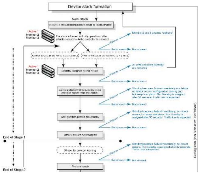
flowchart
graph TD
    A["Device stack formation"] --> B["New Stack"]
    B --> C{Stack is created using memory setup or 'Stack machine';
}
    C --> D["Member 2 and 3 become 'osphorus'"]
    D --> E["Member 1 Member 2 Member 3"]
    E --> F["Startbox signed by the Active"]
    F --> G["Configuration synchronized (running config is opened from the Active)"]
    G --> H["Configuration passed on 'Stackby'"]
    H --> I["Other units are not arranged"]
    I --> J["70 sec fix protocol learning"]
    J --> K["Protocol study"]

    subgraph "Existing steps (or Units with mm and retention)"
        L["Member 1 Member 2 Member 3"] --> M["Startbox signed by the Active"]
        N["Member 2 Member 3"] --> O["Startbox signed by the Active"]
        P["Member 3 Member 2 Member 3"] --> Q["Startbox signed by the Active"]
        R["Member 4 Member 2 Member 3"] --> S["Startbox signed by the Active"]
        T["Member 5 Member 2 Member 3"] --> U["Startbox signed by the Active"]
        V["Member 6 Member 2 Member 3"] --> W["Startbox signed by the Active"]
        X["Member 7 Member 2 Member 3"] --> Y["Startbox signed by the Active"]
        Z["Member 8 Member 2 Member 3"] --> AA["Startbox signed by the Active"]
        AB["Member 9 Member 2 Member 3"] --> AC["Startbox signed by the Active"]
        AD["Member 10 Member 2 Member 3"] --> AE["Startbox signed by the Active"]
        AF["Member 11 Member 2 Member 3"] --> AG["Startbox signed by the Active"]
        AH["Member 12 Member 2 Member 3"] --> AI["Startbox signed by the Active"]
        AJ["Member 13 Member 2 Member 3"] --> AK["Startbox signed by the Active"]
        AL["Member 14 Member 2 Member 3"] --> AM["Startbox signed by the Active"]
        AN["Member 15 Member 2 Member 3"] --> AO["Startbox signed by the Active"]
        AP["Member 16 Member 2 Member 3"] --> AQ["Startbox signed by the Active"]
        AR["Member 17 Member 2 Member 3"] --> AS["Startbox signed by the Active"]
        AT["Member 18 Member 2 Member 3"] --> AU["Startbox signed by the Active"]
        AV["Member 19 Member 2 Member 3"] --> AW["Startbox signed by the Active"]
        AX["Member 20 Member 2 Member 3"] --> AY["Startbox signed by the Active"]
        AZ["Member 21 Member 2 Member 3"] --> BA["Startbox signed by the Active"]
        BB["Member 22 Member 2 Member 3"] --> BC["Startbox signed by the Active"]
        BD["Member 23 Member 2 Member 3"] --> BE["Startbox signed by the Active"]
        BF["Member 24 Member 2 Member 3"] --> BG["Startbox signed by the Active"]
        BH["Member 25 Member 2 Member 3"] --> BH
        BI["Member 26 Member 2 Member 3"] --> BJ["Startbox signed by the Active"]
        BK["Member 27 Member 2 Member 3"] --> BL["Startbox signed by the Active"]
        BM["Member 28 Member 2 Member 3"] --> BN["Startbox signed by the Active"]
        BO["Member 29 Member 2 Member 3"] --> BP["Startbox signed by the Active"]
        BQ["Member 30 Member 2 Member 3"] --> BR["Startbox signed by the Active"]
        BS["Member 31 Member 2 Member 3"] --> BT["Startbox signed by the Active"]
        BU["Member 32 Member 2 Member 3"] --> BV["Startbox signed by the Active"]
        BW["Member 33 Member 2 Member 3"] --> BX["Startbox signed by the Active"]
        BY["Member 34 Member 2 Member 3"] --> BZ["Startbox signed by the Active"]
        CA["Member 35 Member 2 Member 3"] --> CB["Startbox signed by the Active"]
        CC["Member 36 Member 2 Member 3"] --> CD["Startbox signed by the Active"]
        CE["Member 37 Member 2 Member 3"] --> CF["Startbox signed by the Active"]
        GD["Member 38 Member 2 Member 3"] --> DH["Startbox signed by the Active"]
        DI["Member 39 Member 2 Member 3"] --> DJ["Startbox signed by the Active"]
        DK["Member 40 Member 2 Member 3"] --> DL["Startbox signed by the Active"]
    end

    style A fill:#f9f,stroke:#333
    style B fill:#ccf,stroke:#333
    style C fill:#cfc,stroke:#333
    style D fill:#fcc,stroke:#333
    style E fill:#ffc,stroke:#333
    style F fill:#cff,stroke:#333
    style G fill:#ffc,stroke:#333
    style H fill:#ffc,stroke:#333
    style I fill:#ffc,stroke:#333
    style J fill:#ffc,stroke:#333
    style K fill:#ffc,stroke:#333
    style L fill:#ffc,stroke:#333
    style M fill:#ffc,stroke:#333
    style N fill:#ffc,stroke:#333
    style O fill:#ffc,stroke:#333
    style P fill:#ffc,stroke:#333
    style Q fill:#ffc,stroke:#333
    style R fill:#ffc,stroke:#333
    style S fill:#ffc,stroke:#333
    style T fill:#ffc,stroke:#333
    style U fill:#ffc,stroke:#333
    style V fill:#ffc,stroke:#333
    style W fill:#ffc,stroke:#333
    style X fill:#ffc,stroke:#333
    style Y fill:#ffc,stroke:#333
    style Z fill:#ffc,stroke:#333
    style AA fill:#ffc,stroke:#333
    style AB fill:#ffc,stroke:#333
    style AC fill:#ffc,stroke:#333
    style AD fill:#ffc,stroke:#333
    style AE fill:#ffc,stroke:#333
    style AF fill:#ffc,stroke:#333
    style AG fill:#ffc,stroke:#333
    style AH fill:#ffc,stroke:#333
    style AI fill:#ffc,stroke:#333
    style AJ fill:#ffc,stroke:#333
    style AK fill:#ffc,stroke:#333
    style AL fill:#ffc,stroke:#333
    style AM fill:#ffc,stroke:#333
    style AN fill:#ffc,stroke:#333
    style AO fill:#ffc,stroke:#333
    style AP fill:#ffc,stroke:#333
    style AQ fill:#ffc,stroke:#333
    style AR fill:#ffc,stroke:#333
Figure 16 illustrates hitless stacking support during a stack merge.
FIGURE 16 Hitless stacking support during a stack merge
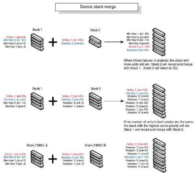
flowchart
graph TD
    A["Stack 1"] -->|Active 1 (pt=30)
Standby 2 (pt=20)
Member 3 (pt=10)
Member 4 (pt=0)| B["Stack 2"]
    B -->|Member 1 (pt=30)
Member 2 (pt=20)
Member 3 (pt=10)
Member 4 (pt=0)
Member 5 (pt=10)
Member 6 (pt=0)| C["Stack 1"]
    C -->|Active 1 (pt=30)
Standby 2 (pt=20)
Member 3 (pt=10)
Member 4 (pt=0)| D["Stack 2"]
    D -->|Active 1 (pt=30)
Standby 2 (pt=20)
Member 3 (pt=0)
Member 4 (pt=0)| E["Stack 1/MAC A"]
    E -->|Active 1 (pt=100)
Standby 2 (pt=50)
Member 3 (pt=0)
Member 4 (pt=0)| F["Stack 2/MAC B"]
    F -->|Active 1 (pt=100)
Standby 2 (pt=50)
Member 3 (pt=0)
Member 4 (pt=0)| G["Stack 1/MAC A"]
    G -->|Active 1 (pt=100)
Standby 2 (pt=50)
Member 3 (pt=0)
Member 4 (pt=0)| H["Stack 2/MAC B"]
    H -->|Active 1 (pt=100)
Standby 2 (pt=50)
Member 3 (pt=0)
Member 4 (pt=0)| I["Stack 1/MAC A"]
    I -->|Active 1 (pt=100)
Standby 2 (pt=50)
Member 3 (pt=0)
Member 4 (pt=0)| J["Stack 2/MAC B"]
    J -->|Active 1 (pt=100)
Standby 2 (pt=50)
Member 3 (pt=0)
Member 4 (pt=0)| K["Stack 1/MAC A"]
    K -->|Active 1 (pt=100)
Standby 2 (pt=50)
Member 3 (pt=0)
Member 4 (pt=0)| L["Stack 2/MAC B"]
    L -->|Active 1 (pt=100)
Standby 2 (pt=50)
Member 3 (pt=0)
Member 4 (pt=0)| M["Stack 1/MAC A"]
    M -->|Active 1 (pt=100)
Standby 2 (pt=50)
Member 3 (pt=0)
Member 4 (pt=0)| N["Stack 2/MAC B"]
    N -->|Active 1 (pt=100)
Standby 2 (pt=50)
Member 3 (pt=0)
Member 4 (pt=0)| O["Stack 1/MAC A"]
    O -->|Active 1 (pt=100)
Standby 2 (pt=50)
Member 3 (pt=0)
Member 4 (pt=0)| P["Stack 2/MAC B"]
    P -->|Active 1 (pt=100)
Standby 2 (pt=50)
Member 3 (pt=0)
Member 4 (pt=0)| Q["Stack 1/MAC A"]
    Q -->|Active 1 (pt=100)
Standby 2 (pt=50)
Member 3 (pt=0)
Member 4 (pt=0)| R["Stack 2/MAC B"]
    R -->|Active 1 (pt=100)
Standby 2 (pt=50)
Member 3 (pt=0)
Member 4 (pt=0)| S["Stack 1/MAC A"]
    S -->|Active 1 (pt=100)
Standby 2 (pt=50)
Member 3 (pt=0)
Member 4 (pt=0)| T["Stack 2/MAC B"]
    T -->|Active 1 (pt=100)
Standby 2 (pt=50)
Member 3 (pt=0)
Member 4 (pt=0)| U["Stack 1/MAC A"]
    U -->|Active 1 (pt=100)
Standby 2 (pt=50)
Member 3 (pt=0)
Member 4 (pt=0)| V["Stack 2/MAC B"]
    V -->|Active 1 (pt=100)
Standby 2 (pt=50)
Member 3 (pt=0)
Member 4 (pt=0)| W["Stack 1/MAC A"]
    W -->|Active 1 (pt=100)
Standby 2 (pt=50)
Member 3 (pt=0)
Member 4 (pt=0)| X["Stack 2/MAC B"]
    X -->|Active 1 (pt=100)
Standby 2 (pt=50)
Member 3 (pt=0)
Member 4 (pt=0)| Y["Stack 1/MAC A"]
    Y -->|Active 1 (pt=100)
Standby 2 (pt=50)
Member 3 (pt=0)
Member 4 (pt=0)| Z["Stack 2/MAC B"]
    Z -->|Active 1 (pt=100)
Standby 2 (pt=50)
Member 3 (pt=0)
Member 4 (pt=0)| AA["Stack 1/MAC A"]
    AA -->|Active 1 (pt=100)
Standby 2 (pt=50)
Member 3 (pt=0)
Member 4 (pt=0)| AB["Stack 2/MAC B"]
    AB -->|Active 1 (pt=100)
Standby 2 (pt=50)
Member 3 (pt=0)
Member 4 (pt=0)| AC["Stack 1/MAC A"]
    AC -->|Active 1 (pt=100)
Standby 2 (pt=50)
Member 3 (pt=0)
Member 4 (pt=0)| AD["Stack 2/MAC B"]
    AD -->|Active 1 (pt=100)
Standby 2 (pt=50)
Member 3 (pt=0)
Member 4 (pt=0)| AE["Stack 1/MAC A"]
    AE -->|Active 1 (pt=100)
Standby 2 (pt=50)
Member 3 (pt=0)
Member 4 (pt=0)| AF["Stack 2/MAC B"]
    AF -->|Active 1 (pt=100)
Standby 2 (pt=50)
Member 3 (pt=0)
Member 4 (pt=0)| AG["Stack 1/MAC A"]
    AG -->|Active 1 (pt=100)
Standby 2 (pt=50)
Member 3 (pt=0)
Member 4 (pt=0)| AH["Stack 2/MAC B"]
    AH -->|Active 1 (pt=100)
Standby 2 (pt=50)
Member 3 (pt=0)
Member 4 (pt=0)| AI["Stack 1/MAC A"]
Figure 17 illustrates hitless stacking support in a stack split.
FIGURE 17 Hitless stacking support in a stack split
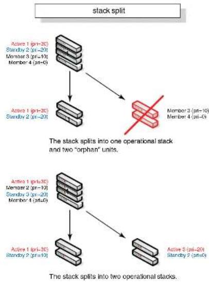
flowchart
graph TD
A["stack split"] --> B["Active 1 (pri=3C)<br>Standby 2 (pri=20)<br>Member 3 (pri=10)<br>Member 4 (pri=0)"]
B --> C["Active 1 (pri=3C)<br>Standby 2 (pri=20)"]
C --> D["The stack splits into one operational stack and two "orphan" units."]
E["Active 1 (pri=3C)<br>Member 2 (pri=10)<br>Standby 3 (pri=20)<br>Member 4 (pri=0)"] --> F["Active 1 (pri=3C)<br>Standby 2 (pri=10)"]
F --> G["The stack splits into two operational stacks."]
H["Active 5 (pri=20)<br>Standby 2 (pri=0)"] --> I["Active 5 (pri=20)"]
I --> J["The stack splits into one operational stack and two "orphan" units."]
K["Member 3 (pri=10)<br>Member 4 (pri=0)"] --> L["Red X"]
M["Active 1 (pri=3C)<br>Standby 2 (pri=20)"]
Hitless stacking default behavior
Hitless stacking is disabled by default. When disabled, the following limitations are in effect:
- If a failover occurs, every unit in the stack will reload
- Manual switchover is not allowed. If the CLI command stack switch-over is entered, the following message will appear on the console:
Switch-over is not allowed. Reason: hitless-failover not configured.
- Internal switchover resulting from a priority change is blocked until the entire stack is reloaded or hitless stacking is enabled. A priority change will trigger an election, but the newly-elected winner will not immediately assume its role. For more information, refer to "Displaying pending device roles" on page 174.
- If there is no Active Controller after a reload, the bootup standby will assume the active role after reloading every unit in the stack, including itself.
- During a stack merge, the Active Controller with the highest priority will win the election and reload every unit of the losing stack.
NOTE
Synchronization between the Active Controller, Standby Controller, and stack members will occur whether or not hitless stacking is enabled.
When hitless stacking is enabled, the following behavior takes effect immediately:
- If a failover occurs, the stack will not reload.
- Manual switchover (CLI command stack switch-over) is allowed.
- If a priority change occurred while hitless stacking was disabled, and the configured priority value requires a switchover, the system will start a 60-second timer before performing a switchover. After the switchover, the highest priority standby will become the Active Controller.
- If there is no Active Controller after a reload, the bootup standby will assume the active role in approximately 60 seconds without a reload.
- During a stack merge, the Active Controller with the larger number of units will win the election and reload every unit of the losing stack. If two stacks have the same number of units, then the
Enabling hitless stacking
Hitless stacking is disabled by default. To enable it, enable hitless failover as described in "Enabling hitless failover" on page 175.
Displaying hitless stacking status
You can use the show stack command to view whether or not hitless stacking is enabled. The following example shows that hitless stacking is disabled.
PowerConnectShow stack
alone: standalone, D: dynamic config, S: static config
ID Type Role Mac Address Pri State Comment
2 S FCX6485 member 0000.0000.0000 0 reserve
3 S FCX624 member 0024.3976.2640 0 remote Ready
5 S FCX624 standby 0Ge0.5200.0400 100 remote Ready
6 S FCX668 active 0024.3977.7980 128 local Ready
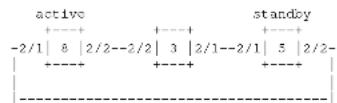
Standby u5 - No hitless failover. Reason: hitless-failover not configured
Syntax: show stack
Displaying pending device roles
When hitless stacking is disabled, a priority change will trigger an election, but the newly-elected winner will not assume its role until the entire stack is reloaded or hitless stacking is enabled.
You can use the show stack command to view pending device roles. The "Role" column displays the current role for each unit. The "Comment" column displays the role that will take effect after a load or when hitless stacking is enabled.
Syntax: show stack
Hitless stacking failover
Hitless stacking failover provides automatic failover from the Active Controller to the Standby Controller without resetting any of the units in the stack and with sub-second or no packet loss to hitless stacking-supported services and protocols.
For a description of the events that occur during a hitless failover, refer to "What happens during a hitless stacking switchover or failover" on page 166.
For a description this feature's impact to major system functions, refer to Table 37 on page 164.
For an example of hitless failover operation, refer to "Hitless stacking failover example" on page 176.
For feature limitations and configuration notes, refer to "Configuration notes and feature limitations" on page 165.
Enabling hitless failover
To enable hitless failover, enter the following command at the Global CONFIG level of the CLI: PowerConnect{config}#hitless-failover enable
The command takes effect immediately. Hitless switchover is allowed, and in the event of a failover, the standby controller will take over the active role without reloading the stack.
Syntax: [no] hitless-failover enable
Use the no form of the command to disable hitless stacking once it has been enabled.
Hitless stacking failover example
Figure 18 illustrates hitless stacking failover operation when the Active Controller fails.
FIGURE 18 Hitless stacking failover when the Active Controller fails
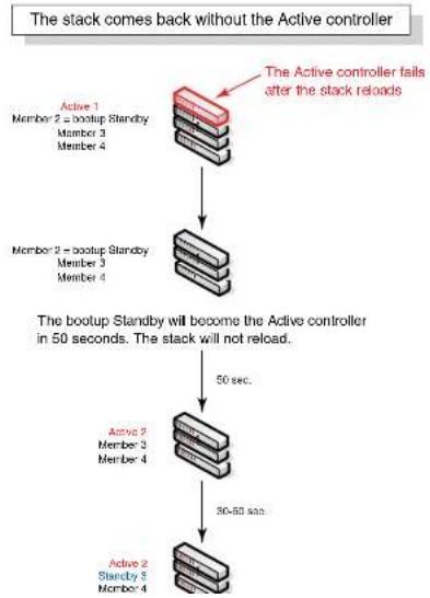
flowchart
graph TD
    A["Active 1\nMember 2 = bootup Standby\nMember 3\nMember 4"] --> B["The Active controller fails after the stack reloads"]
    B --> C["Member 2 = bootup Standby\nMember 3\nMember 4"]
    C --> D["50 sec."]
    D --> E["Active 2\nMember 3\nMember 4"]
    E --> F["30-60 sec."]
    F --> G["Active 2\nStandby 3\nMember 4"]
    G --> H["50 sec."]
    H --> I["The bootup Standby will become the Active controller in 50 seconds. The stack will not reload."]
For a description this feature's impact to major system functions, refer to Table 37 on page 164.
For examples of hitless stacking switchover operation, refer to "Hitless stacking switchover examples" on page 178.
Executing a hitless stacking switchover
The following must be in effect before a hitless switchover (switch over to the Standby Controller) is allowed:
- Hitless stacking is enabled
• The stack has a Standby Controller
• The Standby Controller has learned the protocols - The Standby Controller has the same priority as the Active Controller
- More than 120 seconds have passed since the previous switchover or failover
You can use the show stack command to view whether or not these properties are in effect. For more information, see "Displaying information about hitless stacking" on page 183.
To perform a switchover, enter the following command:
PowerConnect# stack switch over Standby unit 8 will become Active Controller, and unit 1 will become standby Are you sure? (enter 'y' or 'n'): y Unit 1 is no longer the Active Controller
Syntax: stack switch-over
Hitless stacking switchover examples
This section illustrates hitless stacking failover and switchover operation during a CLI-driven
switchover or priority change.
Figure 19 illustrates a hitless stacking switchover triggered by the stack switch-over command.
FIGURE 19 Manual switchover

flowchart
graph TD
    A["Device stack manual switchover"] --> B["Execute "stack switch-over""]
    B --> C{No waiting period}
    C -->|Yes| D["The Active and Standby priorities must match or the command is rejected"]
    C -->|No| E["Next switchover allowed in 120 seconds"]
    D --> F["The Active and Standby controllers switch roles immediately (no waiting period). No traffic loss is expected."]
    E --> G["Next switchover allowed in 120 seconds"]
Figure 20 illustrates a hitless stacking switchover when the Active Controller goes down then comes back up. The stack in this example has user configured priorities.
FIGURE 20 Hitless stacking switchover when the Active Controller comes back up

flowchart
graph TD
    A["Active controller comes back (in a stack with user-assigned priorities)"] --> B{The Active controller fails}
    B -->|Yes| C["Active (Unit 1 with priority 200) comes back up"]
    C --> D{Active (Unit 1 with priority 200) reloads because it loses the election. After the reload, it joins the stack as a member.}
    D -->|Yes| E["30 sec."]
    D -->|No| F["70 sec."]
    E --> G["Standby 1 (on-600) Active 2 (on-100) Member 3 (on-2) Member 4 (on-3)"]
    F --> H["Standby 1 (on-600) Active 2 (on-100) Member 3 (on-2) Member 4 (on-3)"]
Figure 21 illustrates a hitless stacking switchover after the network administrator increases the priority value of the Standby Controller.
FIGURE 21 Scenario 1 - Hitless stacking switchover after a priority change
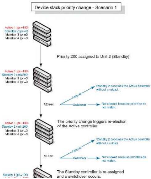
flowchart
graph TD
    A["Device stack priority change - Scenario 1"] --> B["Priority 200 assigned to Unit 2 (Standby)"]
    B --> C["Active 1 (pr=100)<br>Standby 2 (pr=0)<br>Member 3 (pr=0)<br>Member 4 (pr=0)"]
    C --> D["120 sec."]
    D --> E["The priority change triggers re-election of the Active controller"]
    E --> F["Active 1 (pr=100)<br>Standby 2 (pr=200)<br>Member 3 (pr=0)<br>Member 4 (pr=0)"]
    F --> G["60 sec."]
    G --> H["The Standby controller is re-assigned and a switchover occurs."]
    style A fill:#f9f,stroke:#333
    style H fill:#f9f,stroke:#333
Figure 22 illustrates a hitless stacking switchover after the network administrator increases the priority value of one of the stack members.
FIGURE 22 Scenario 2 - Hitless stacking switchover after a priority change

flowchart
graph TD
    A["Device stack priority change - Scenario 2"] --> B["Priority 200 assigned to Unit 3"]
    B --> C["The priority change triggers re-election of the Active controller"]
    C --> D["Active 1 (pil=100)<br>Standby 2 (ptr-0)<br>Member 3 (ptr-0)<br>Member 4 (ptr-0)"]
    D --> E["Active 1 (pil=100)<br>Standby 2 (ptr-0)<br>Member 3 (ptr-200)<br>Member 4 (ptr-0)"]
    E --> F["Active 1 (pil=100)<br>Standby 2 (ptr-0)<br>Member 3 (ptr-200)<br>Member 4 (ptr-0)"]
    F --> G["A switchover occurs.<br>Stages 1 and 2 are complete."]
    G --> H["The Standby controller is re-assigned"]
    H --> I["Sendby 1 (pil=100)<br>Member 2 (ptr-0)<br>Active 3 (ptr-200)<br>Member 4 (ptr-0)"]
Figure 23 illustrates a hitless stacking switchover after the network administrator increases the priority value for two of the stack members.
FIGURE 23 Scenario 3 - Hitless stacking switchover after a priority change
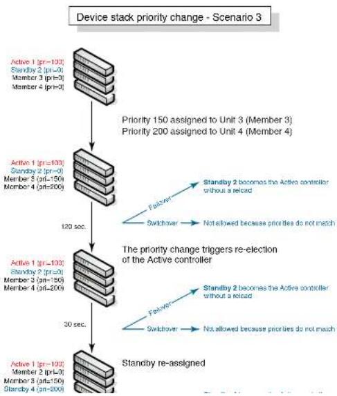
flowchart
graph TD
    A["Device stack priority change - Scenario 3"] --> B["Activity 1 (pr=103)"]
    B --> C["Standby 2 (pr=0)"]
    C --> D["Member 3 (pr=0)"]
    D --> E["Member 4 (pr=0)"]
    E --> F["Activity 1 (pr=103)"]
    F --> G["Standby 2 (pr=0)"]
    G --> H["Member 5 (pr=150)"]
    H --> I["Member 4 (pr=200)"]
    I --> J["Activity 1 (pr=103)"]
    J --> K["Standby 2 (pr=0)"]
    K --> L["Member 3 (pr=126)"]
    L --> M["Member 4 (pr=200)"]
    M --> N["Activity 1 (pr=103)"]
    N --> O["Standby 2 (pr=0)"]
    O --> P["Member 3 (pr=150)"]
    P --> Q["Member 4 (pr=200)"]
    Q --> R["Activity 1 (pr=103)"]
    R --> S["Standby 2 (pr=0)"]
    S --> T["Member 3 (pr=150)"]
    T --> U["Member 4 (pr=200)"]
    U --> V["Activity 1 (pr=103)"]
    V --> W["Standby 2 (pr=0)"]
    W --> X["Member 3 (pr=150)"]
    X --> Y["Member 4 (pr=200)"]
    Y --> Z["Activity 1 (pr=103)"]
    Z --> AA["Standby 2 (pr=0)"]
    AA --> AB["Member 3 (pr=150)"]
    AB --> AC["Member 4 (pr=200)"]
    AC --> AD["Activity 1 (pr=103)"]
    AD --> AE["Standby 2 (pr=0)"]
    AE --> AF["Member 3 (pr=150)"]
    AF --> AG["Member 4 (pr=200)"]
    AG --> AH["Activity 1 (pr=103)"]
    AH --> AI["Standby 2 (pr=0)"]
    AI --> AJ["Member 3 (pr=150)"]
    AJ --> AK["Member 4 (pr=200)"]
    AK --> AL["Activity 1 (pr=103)"]
    AL --> AM["Standby 2 (pr=0)"]
    AM --> AN["Member 3 (pr=150)"]
    AN --> AO["Member 4 (pr=200)"]
    AO --> AP["Activity 1 (pr=103)"]
    AP --> AQ["Standby 2 (pr=0)"]
    AQ --> AR["Member 3 (pr=150)"]
    AR --> AS["Member 4 (pr=200)"]
Displaying information about hitless stacking
Use the show stack command to view information pertinent to a hitless stacking switchover or failover. The command output illustrates the Active and Standby Controllers, as well as the readiness of the Standby Controller to take over the role of Active Controller, if needed.
PowerConnect#show stack
alone: standalone, D: dynamic config, S: static config
ID Type Role Mac Address Pri State Comment
1 S FCX624S active 00e0.5200.2900 128 local Ready
2 S FCX624S standby 00c0.5200.0100 128 remote Ready
3 S FCX624S member 0000.0000.0000 128 reserve
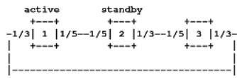
Standby unit 2: protocols ready, can failover or manually switch over Current stack management MAC is 0000.5200.1100
NOTE
The text in bold highlights the information added for hitless stacking failover and switchover. For a description of the fields in this output, see "Field descriptions for the show stack command" on page 137.
Syslog messages for hitless stacking failover and switchover
Syslog messages are generated for the following events:
- Switchover
To view the System log or the traps logged on an SNMP trap receiver, enter the show log command at any level of the CLI. The following example output shows what the log might look like after a switchover or assignment of the Standby Controller.
PowerConnect# show log
Syslog logging: enabled (0 messages dropped, 1 flushes, 0 overruns)
Buffer logging: level ACDMETNN, B messages logged
level code: A-alert C-critical D-debugging M-emergency E-error
I=informational N=notification N=warningDynamic Log Buffer (50 lines):
0d00h05m34s:1:System: Interface ethernet mgmtl, state up
0d00h05m33s:I:Stack: Stack unit 8 has been assigned as STANDBY unit of the stack system
odvohosmiss:1:Stack: Stack is operational due to SWITCH-OVER
0d00h05m32s:1:Stack: Stack unit 1 has been elected as ACTIVE unit of the stack system
0d00h05m29s:W:System:Stack unit 2 Fan speed changed automatically to 2
0d00h05m25s;W:System:Stack unit 5 Fan speed changed automatically to 2
Od00h05m00s:I:System: Interface ethernet mgmt1, state down
Cd00h05m00s:I:Security: Telnet server enabled by from session
The following example output shows what the log might look like after a failover of the Active Controller.
PowerConnect# show log
Syslog logging: enabled (0 messages dropped, 0 flushes, 0 overruns)
Buffer logging: level ACDMEINW, 12 messages logged
level code: A=alert C=critical D=dbugging M=emergency E=error
I=informational N=notification S=warning
Dynamic Log Buffer (50 lines):
Od0Ch04m41s:T:Stack: Stack unit 3 has been assigned as STANDBY unit of the stack system
OdUChD4m12s:I:System: Interface ethernet mgmt1, state up
Od00h04m10s:T:System: Interface ethernet mgmt1, state down
Od0Ch04ml0s:I:System: Interface ethernet mgmt1, state up
Od0Ch04m09s:I:STP: VLAN 1 Bridge is RootBridge: 800000e052010000 (MgmtPriChg)
Od0Ch04m09s:1:System: Management MAC address changed to 00e0.5201.0000
Od0Ch04m09s:I:Stack: Stack is operational due to FAIL-OVER
Od00h04m08s:I:Stack: Stack unit 1 has been elected as ACTIVE unit of the stack system
Od0Ch04m08s:1:STP: VLAN 1 Port 8/1/1 STP State -> DISABLED (PortDown)
PowerConnect# debug stacking sync_rel_msq 4
stk_sync_trunk_mapping:sending trunk mapping...
start running config sync
sync_cdb:send cdb:sess = 0, pBuf = 2132f068
sync_cdb:send cdb:sess = 0, pBuf = 2132f57c
...
stk_sync_cdb:finished cdb sync
PowerConnect# debug stacking sync_rei_msg 8
Hitless sync: TRUNK INFO size (1282)
**********************************************************************
Trunk ID: 10 (1 based), (Hw Trunk ID: 1),
g_sw_sys.trunk_config.trunk_entry[#9]
:number_of_ports = 2; creator = 0
g_sw_sys.trunk_config.trunk_entry[#9] MEMBER PORTS
port_list[0]=#009
port_list[1]=#010
Syntax: debug stacking sync_rel_msg
PowerConnect B-Series FCX hitless stacking
Monitoring Hardware Components
Chapter
6
Table 39 lists the individual Dell PowerConnect switches and the hardware monitoring features they support.
TABLE 39 Supported hardware monitoring features
| Feature | PowerConnect B-Series FCX |
| Virtual cable testing (VCT) Yes | |
| Digital optical monitoring Yes |
The procedures in this chapter describe how to configure the software to monitor hardware components.
Virtual cable testing
PowerConnect devices support Virtual Cable Test (VCT) technology. VCT technology enables the diagnosis of a conductor (wire or cable) by sending a pulsed signal into the conductor, then examining the reflection of that pulse. This method of cable analysis is referred to as Time Domain Reflectometry (TDR). By examining the reflection, the Dell PowerConnect device can detect and report cable statistics such as local and remote link pair, cable length, and link status.
Configuration notes
• This feature is supported on copper ports only. It is not supported on fiber ports.
- The port to which the cable is connected must be enabled when you issue the command to diagnose the cable. If the port is disabled, the command is replaced
Syntax: phy cable-diag tdr
Specify the
• PowerConnect B-Series FCX stackable switches -
Viewing the results of the cable analysis
To display the results of the cable analysis, enter a command such as the following at the Privileged EXEC level of the CLI.
| PowerConnect>show cable-diag Ldr 1 | |||||
| Port | Speed | Local pair | Pair Length | Remote pair | Pair status |
| 01 | 1000M | Pair A | <50M | Pair B | Terminated |
| Pair B | <50M | Pair A | Terminated | ||
| Pair C | <50M | Pair D | Terminated | ||
| Pair D | <50M | Pair C | Terminated | ||
In the above output, Local pair indicates the assignment of wire pairs from left to right, where Pair A is the left-most pair. Table 40 shows the Local pair mapping to the T568A pin/pair and color assignment from the TIA/EIA-568-B standard.
TABLE 40 Local pair definition
| Local pair T568A pair and color assignment |
| Pair A Pair 3 (green) |
| Pair B Pair 2 (orange) |
| Pair C Pair 1 (blue) |
| Pair D Pair 4 (brown) |
Figure 24 illustrates the T568A pin/pair assignment.
FIGURE 24 T568A pin/pair assignment
Pair 2
Orange
Specify the
• PowerConnect B-Series FCX stackable switches -
Table 41 defines the fields shown in the command output.
TABLE 41 Cable statistics
| This line... Displays... |
| Port The port that was tested. |
| Speed The port current line speed. |
| Local pair The local link name. Refer to Table 40. |
| Pair Length The cable length when terminated, or the distance to the point of fault when the line is not up. |
| Remote pair The remote link name. |
| Pair status The status of the link. This field displays one of the following:• Terminated: The link is up.• Shorted: A short is detected In the cable,• Open: An opening is detected in the cable.• ImpedMis: The impedance is mismatched.• Failed: The TDR test failed. |
Supported Fiber Optic Transceivers
Table 42 lists the Small Form-Factor Pluggable (SFP) and 10-Gigabit Small Form Factor Pluggable (XFP) fiber optic transceivers supported on PowerConnect devices.
TABLE 42 Supported fiber optic transceivers
| Label | Manufacturing part number | Type | Dell part number | Supports Digital Optical Monitoring? |
| E1MG-BXD | TRPBG1LXDBVS2FY | 1000Base-BXD | PYD7H | No |
| E1MG-RXU | TRPBG1LXDRBSHEY | 1000Base-RXU | YDWGM | No |
| 10G-XFP-SR FTLX8511D3-F1AFBR-720XPDZ-FD1PLRXXL-SC-S43-59TRF2001EN-GA250 | 10GBasc-SR XFP YY0VX Ycs | |||
| 10G-SFPP-SR FTLX8571D3BNL-B2AFBR-703ASDZ-BR2 | 10GE SR SFP+ DR7C1 Yes | |||
| 10G-SFPP-LR FTLX1471D3BNL-B2AFCT-701ASDZ-BR2 | 10GE LR SFP+ 6D0R3 Ycs | |||
| XDL-10G SFPP TWX-0101 | 5798900062GSPWWA-BEB-EN | DIRECT ATTACHED SFPP COPPER,1M,1 PACK | 60HMX | No |
| XDL-10G-SFPP-TWX-0301 | 5798900042GSPWWB-BFB EN | DIRECT ATTACHED SFPP COPPER,3M,1-PACK | GPPHR No | |
| XDL-10G-SFPP-TWX-0501 | 5798900012GSPWWC-BGB-EN | DIRECT ATTACHED SFPP COPPER,5M,1-PACK | D93W5 | No |
Digital optical monitoring
You can configure your Brocade device to monitor optical transceivers in the system, either globally or by specified ports. When this feature is enabled, the system will monitor the temperature and signal power levels for the optical transceivers in the specified ports. Console messages and Syslog messages are sent when optical operating conditions fall below or rise above the XFP or SFP manufacturer recommended thresholds.
Table 42 on page 191 specifies which Dell-qualified media types support digital optical monitoring.
Configuration limitations
Use the no form of the command to disable digital optical monitoring.
Setting the alarm interval
You can optionally change the interval between which alarms and warning messages are sent. The default interval is three minutes. To change the interval, use the following command.
PowerConnect{config}#interface ethernet 1/1 to 1/2
PowerConnect (config-mif-e10000-1/1-1/2) #optical-monitor 10
Syntax: [no] optical-monitor [
For
NOTE
The commands no optical-monitor and optical-monitor 0 perform the same function. That is, they both disable digital optical monitoring.
Displaying information about installed media
Use the show media, show media slot, and show media ethernet commands to obtain information about the media devices installed per device, per slot, and per port. The results displayed from these commands provide the Type, Vendor, Part number, Version and Serial number of the SFP or XFP optical device installed in the port. 1G M-C indicates 1b Gbps copper media. If no SFP or XFP device is installed in a port, the "Type" field will display "EMPTY".
Use the show media command to obtain information about the media devices installed in a device.
PowerConnect#show media
Part 1: Type : 1G M-SX2(SFP)
Vendor: Brocade Communications, Inc. Version: 0000
Part#: TRPAG1XRPBSS-FY Serial#: 0635000468
Port 2: Type : EMPTY
Port 3: Type : EMPTY
Port 4: Type : 100M M-FX-SR(SFP)
Vendons: Nussels, Communal cold chain. The Vendons:
Port 24: Type : 1G M-C
Port 25: Type : 10G XG-SR(XFF)
Vendor: Brocade Communications Inc. Version: 02
Partt : JX2R018W05306 Serial#: F617604000A3
Port 26: Type : EMPTY
Use the show media slot command to obtain information about the media device installed in a slot.
PowerConnect+show media slot 1
Port 1/1: Type : 1G M-SX(SFP)
    Vendor: Brocade Communications, Inc. Version:
    Part#: PL-XPL-VC-813-19 Serial#: 425HC103
Port 1/2: Type : 1G M-SX(SFP)
    Vendor: Brocade Communications, Inc. Version:
    Part#: PL-XPL-VC-813-19 Serial#: 411HC0AH
Port 1/3: Type : EMPTY
Port 1/4: Type : 1G M-SX(SFP)
    Vendor: Brocade Communications, Inc. Version: XI
    Part#: FTRJ-8519-3 Serial#: H11654K
Port 1/5: Type : EMPTY
Port 1/6: Type : EMPTY
Port 1/7: Type : 100M M-FX-IR(SFP)
    Vendor: Brocade Communications, Inc. Version: A
    Part#: FTLF1323P1BTR-TD Serial#: OCT000T
Port 1/8: Type : EMPTY
Port 1/9: Type : 100M M-FX-LR(STP)
    Vendor: Brocade Communications, Inc. Version: A
    Part#: FTLF1323P1BTL-TD Serial#: UD3085J
Port 1/10: Type : EMPTY
Port 1/11: Type : 100M M-FX-SR(SFP)
    Vendor: Brocade Communications, Inc. Version: A
    Part#: FTLF1217P2STL-FI Serial#: UCC003J
Port 1/12: Type : EMPTY
Port 1/13: Type : 100M M-FX-IR(SFP)
    Vendor: Brocade Communications, Inc. Version: A
    Part#: FTLF1323P1BTR-TI Serial#: PCA2XC5
Use the show media ethernet command to obtain information about the media device installed in a port.
Digital optical monitoring
Normal
Normal
Normal
Normal
Syntax: show optic
NOTE
The show optic function takes advantage of information stored and supplied by the manufacturer of the XFP or SFP transceiver. This information is an optional feature of the Multi-Source Agreement standard defining the optical interface. Not all component suppliers have implemented this feature set. In such cases where the XFP or SFP transceiver does not supply the information, a "Not Available" message will be displayed for the specific port on which the module is installed.
The following table describes the information displayed by the show optic command.
TABLE 43 Output from the show optic command
This field... Displays...
| Port The Doll port number. | |
| Temperature | The operating temperature, in degrees Celsius, of the optical transceiver.The alarm status, as described in Table 44. |
| Tx Power | The transmit power signal, in decibels (dB), of the measured power referenced to one milliwatt (mW).The alarm status, as described in Table 44. |
| Rx Power | The receive power signal, in decibels (dB), of the measured power referenced to one milliwatt (mW).The alarm status, as described in Table 44 |
| Tx Bias Current | The transmit bias power signal, in milliamperes (mA).The alarm status, as described in Table 44. |
For Temperature, Tx Power, Rx Power, and Tx Bias Current in the show optic command output, values are displayed along with one of the following alarm status values: Low-Alarm, Low-Warn, Normal, High-Warn or High-Alarm. The thresholds that determine these status values are set by the manufacturer of the optical transceivers. Table 44 describes each of these status values.
TARI F 44 Alarm status value description
Viewing optical transceiver thresholds
The thresholds that determine the alarm status values for an optical transceiver are set by the manufacturer of the XFP or SFP. To view the thresholds for a qualified optical transceiver in a particular port, use the show optic threshold command as shown below.
| Port 2/2 sfp monitor thresholds: | ||
| Temperature High alarm | 5a00 | 90.0000 C |
| Temperature Low alarm | d300 | -45.0000 C |
| Temperature High warning | 5500 | 85.0000 C |
| Temperature Low warning | d800 | -40.0000 C |
| Supply Voltage High alarm | 9088 | |
| Supply Voltage Low alarm | 7148 | |
| Supply Voltage High warning | 8ca0 | |
| Supply Voltage Low warning | 7530 | |
| TX Blas High alarm | 7530 | 60.000 mA |
| TX Blas Low alarm | 01f4 | 1.000 mA |
| TX Blas High warning | 61a8 | 50.000 mA |
| TX Blas Low warning | 05dc | 3.000 mA |
| TX Power High alarm | 1f07 | -001.0001 dBm |
| TX Power Low alarm | 02c4 | -011.4996 dBm |
| TX Power High warning | 18a6 | -001.9997 dBm |
| TX Power Low warning | 037b | -010.5012 dBm |
| RX Power High alarm | 2710 | 000.0000 dBm |
| RX Power Low alarm | 0028 | -023.9794 dBm |
| RX Power High warning | 1f07 | -001.0001 dBm |
| RX Power Low warning | 0032 | -023.0102 dBm |
Syntax: show optic threshold
Specify the
PowerConnect B-Series FCX stackable switches -
For Temperature, Supply Voltage, TX Bias, TX Power, and RX Power, values are displayed for each of the following four alarm and warning settings: High alarm, Low alarm, High warning, and Low warning. The hexadecimal values are the manufacturer internal calibrations, as defined in the SFF-8472 standard. The other values indicate at what level (above the high setting or below the
Configuring IPv6 Management on PowerConnect B-Series FCXSwitches
Chapter
7
Table 45 lists the individual Dell PowerConnect switches and the IPv6 management features they support.
NOTE
The following table only shows the IPv6 management features that are supported. Full IPv6 L2/L3 support will be added in a future release.
TABLE 45 Supported IPv6 management features
| Feature PowerConnect B-Series FCX | |
| Link-Local IPv6 address | Yes |
| IPv6 copy ^1 | Yes |
| IPv6 ncopy ^1 | Yes |
| IPv6 debug | Yes |
| IPv6 access-list (management ACLs) | Yes |
| IPv6 ping | Yes |
| IPv6 traceroute | Yes |
| DNS server name resolution | Yes |
| HTTP/HTTPS | Yes |
| Logging (Syslog) | Yes |
| RADIUS ^1 | Yes |
| SCP | Yes |
This chapter describes the IPv6 management features, including command syntax and management examples.
IPv6 management overview
IPv6 was designed to replace IPv4, the Internet protocol that is most commonly used currently throughout the world. IPv6 increases the number of network address bits from 32 (IPv4) to 128, which provides more than enough unique IP addresses to support all of the network devices on the planet into the future. IPv6 is expected to quickly become the network standard.
Dell PowerConnect devices that support IPv6 may be used as management hosts. Interfaces on these devices are configured with IPv6 addresses, but do not have full IPv6 routing enabled. IPv6 is available on all Dell PowerConnect devices that are running Layer 2, base Layer 3, or full Layer 3 software images.
NOTE
Dell PowerConnect devices can serve as management hosts on an IPv6 network. However, IPv6 routing functionality is not supported for these devices.
IPv6 addressing
IPv4 is limited because of the 32-bit addressing format, which cannot satisfy potential increases in the number of users, geographical needs, and emerging applications. To address this limitation, IPv6 introduces a new 128-bit addressing format.
An IPv6 address is composed of 8 fields of 16-bit hexadecimal values separated by colons (:). Figure 25 shows the IPv6 address format.
FIGURE 25 IPv6 address format

• The hexadecimal letters in IPv6 addresses are not case-sensitive
As shown in Figure 25, the IPv6 network prefix is composed of the left-most bits of the address. As with an IPv4 address, you can specify the IPv6 prefix using the
The
The
The following is an example of an IPv6 prefix.
2001:FF08:49EA:D088::/64
Enabling and disabling IPv6
IPv6 is enabled by default for Dell PowerConnect devices that support it. If desired, you can disable IPv6 on a global basis on an device by entering the following command at the Global CONFIG level of the CLI.
PowerConnect(config)#no ipv6 enable
Syntax: no ipv6 enable
To re-enable IPv6 after it has been disabled, enter the ipv6 enable command.
IPv6 management features
This section describes the CLI management commands that are available to Dell PowerConnect devices that support IPv6.
IPv6 management ACLs
When you enter the IPv6 access-list command, the Dell PowerConnect device enters the IPv6 Access List configuration level, where you can access several commands for configuring IPv6 ACL
IPv6 debug
The debug ipv6 commands enable the collection of information about IPv6 configurations for troubleshooting.
Syntax: debug ipv6
- address - IPv6 address
- cache - IPv6 cache entry
- icmp - ICMPv6
- mld - MLD protocol activity
-
- nd - neighbor discovery
- packet - IPv6 packet
• ra - router add
IPv6 Web management using HTTP and HTTPS
When you have an IPv6 management station connected to a switch with an IPv6 address applied to the management port, you can manage the switch from a Web browser by entering http://[
NOTE
You must enclose the IPv6 address with square brackets [ ] in order for the Web browser to work.
Restricting web access
You can restrict Web management access to include only management functions on a Dell PowerConnect device that is acting as an IPv6 host, or restrict access so that the PowerConnect
Restricting Web management access to an IPv6 host
You can specify a single device with an IPv6 address to have Web management access to the host device. No other device except the one with the specified IPv6 address can access the Web Management Interface.
Example
PowerConnect{config}#web client ipv6 3000:2383:e0bb::2/128
Syntax: web client ipv6
The
IPv6 logging
This feature allows you to specify an IPv6 server as the Syslog server.
Specifying an IPv6 Syslog server
To specify an IPv6 Syslog server, enter the log host ipv6 command as shown below.
Example
PowerConnect(config)#log host ipv6 2000:2383:e0bb::4/128
Syntax: [no] log host ipv6
The
The
Name-to-IPv6 address resolution using IPv6 DNS server
The Domain Name Server (DNS) resolver feature lets you use a host name to perform Telnet, ping, and Iraceroute commands. You can also define a DNS domain on a Dell PowerConnect device and
AAAA DNS records are analogous to the A DNS records used with IPv4. They store a complete IPv6 address in each record. AAAA records have a type value of 28.
To establish an IPv6 DNS entry for the device, enter the following command.
PowerConnect(config)#ipv6 dns domain-name companynet.com
Syntax: [no] ipv6 dns domain-name
To define an IPv6 DNS server address, enter the following command.
PowerConnect(config)#ipv6 dns server-address 200::1
Syntax: [no] ipv6 dns server-address
As an example, in a configuration where ftp6.companynet.com is a server with an IPv6 protocol stack, when a user pings ftp6.companynet.com, the Dell PowerConnect device attempts to resolve the AAAA DNS record. In addition, if the DNS server does not have an IPv6 address, as long as it is able to resolve AAAA records, it can still respond to DNS queries.
IPv6 ping
The ping command allows you to verify the connectivity from a Dell PowerConnect device to an IPv6 device by performing an ICMP for IPv6 echo test.
For example, to ping a device with the IPv6 address of 2001:3424:847f:a385:34dd::45 from the Dell PowerConnect device, enter the following command:
PowerConnecting ipv6 2001:3424:847f:a385:34dd::45
Syntax: ping ipv6
- The
- The outgoing-interface keyword specifies a physical interface over which you can verify connectivity. If you specify a physical interface, such as an Ethernet interface, you must also
- The size
parameter specifies the size of the ICMP data portion of the packet. This is the payload and does not include the header. You can specify from 0 - 10173. The default is 16. - The no-fragment keyword turns on the "do not fragment" bit in the IPv6 header of the ping packet. This option is disabled by default.
- The quiet keyword hides informational messages such as a summary of the ping parameters sent to the device, and instead only displays messages indicating the success or failure of the ping. This option is disabled by default.
- The verify keyword verifies that the data in the echo packet (the reply packet) is the same as the data in the echo request (the ping). By default the device does not verify the data.
- The data <1 - 4 byte hex> parameter lets you specify a specific data pattern for the payload instead of the default data pattern, "abcd", in the packet's data payload. The pattern repeats itself throughout the ICMP message (payload) portion of the packet.
NOTE
For parameters that require a numeric value, the CLI does not check whether the value you enter is within the allowed range. Instead, if you do exceed the range for a numeric value, the software rounds the value to the nearest valid value.
- The brief keyword causes ping test characters to be displayed. The following ping test characters are supported.
! Indicates that a reply was received.
. Indicates that the network server timed out while waiting for a reply.
U Indicates that a destination unreachable error PDU was received.
I Indicates that the user interrupted ping.
SNTP over IPv6
To enable the Dell PowerConnect device to send SNTP packets over IPv6, enter a command such as the following at the Global CONFIG level of the CLI.
Syntax: snmp-server host ipv6
The
Secure Shell, SCP, and IPv6
Secure Shell (SSH) is a mechanism that allows secure remote access to management functions on the Dell PowerConnect device. SSH provides a function similar to Telnet. You can log in to and configure the Dell PowerConnect device using a publicly or commercially available SSH client program, just as you can with Telnet. However, unlike Telnet, which provides no security, SSH provides a secure, encrypted connection to the Dell PowerConnect device.
To open an SSH session between an IPv6 host running an SSH client program and the Dell PowerConnect device, open the SSH client program and specify the IPv6 address of the device. For more information about configuring SSH on the Dell PowerConnect device, refer to "Configuring SSH2 and SCP" on page 1203.
IPv6 Telnet
Telnet sessions can be established between a Dell PowerConnect device to a remote IPv6 host, and from a remote IPv6 host to the Dell PowerConnect device using IPv6 addresses.
The telnet command establishes a Telnet connection from a Dell PowerConnect device to a remote IPv6 host using the console. Up to five read-access Telnet sessions are supported on the router at one time. Write-access through Telnet is limited to one session, and only one outgoing Telnet session is supported on the router at one time. To see the number of open Telnet sessions at any time, enter the show telnet command.
Example
To establish a Telnet connection to a remote host with the IPv6 address of 3001:2837:3de2:c37::6, enter the following command.
PowerConnect|telnet 3001:2837:3de2:c37::6
IPv6 traceroute
The traceroute command allows you to trace a path from the Dell PowerConnect device to an IPv6 host.
The CLI displays trace route information for each hop as soon as the information is received. Traceroute requests display all responses to a minimum TTL of 1 second and a maximum TTL of 30 seconds. In addition, if there are multiple equal-cost routes to the destination, the Dell PowerConnect device displays up to three responses.
For example, to trace the path from the Dell PowerConnect device to a host with an IPv6 address of 3301:23dd:349e:a384::34, enter the following command.
PowerConnect41.raceroute ipv6 3301:23dd:349e:a384::34
Syntax: traceroute ipv6
The
IPv6 management commands
The following management CLI commands are available in Dell PowerConnect devices that support IPv6:
• show ipv6 traffic
- clear ipv6 traffic
• show ipv6 TCP
• show ipv6 access-list
• show ipv6 neighbor
- clear ipv6 neighbor
Configuring Spanning Tree Protocol (STP) Related Features
Table 46 lists the individual Dell PowerConnect switches and the Spanning Tree Protocol (STP) features they support.
TABLE 46 Supported STP features
| Feature PowerConnect B-Series FCX | |
| 802.1s Multiple Spanning Tree Yes | |
| 802.1W Rapid Spanning Tree (RSTP) Yes | |
| 802.1D Spanning Tree Support Yes | |
| Enhanced IronSpan support includes Fast Port Span, Fast Uplink Span, and Single Instance Span | Yes |
| PowerConnect Layer 2 devices (switches) support up to 254 spanning tree instances for VLANs. | Yes |
| PowerConnect Layer 3 devices (routers) support up to 254 spanning tree instances for VLANs. | Yes |
| PVST/PVST+ compatibility Yes | |
| PVRST+ compatibility Yes | |
| BPDU Guard Yes | |
| Root Guard Yes | |
| Error disable recovery | Yes |
Configuring standard STP parameters
Layer 2 Switches and Layer 3 Switches support standard STP as described in the IEEE 802.1D specification. STP is enabled by default on Layer 2 Switches but disabled by default on Layer 3 Switches.
By default, each port-based VLAN on a Dell PowerConnect device runs a separate spanning tree (a separate instance of STP). A Dell PowerConnect device has one port-based VLAN (VLAN 1) by default that contains all the device ports. Thus, by default each Dell PowerConnect device has one spanning tree. However, if you configure additional port-based VLANs on a Dell PowerConnect device, then each of those VLANs on which STP is enabled and VLAN 1 all run separate spanning trees.
If you configure a port-based VLAN on the device, the VLAN has the same STP state as the default STP state on the device. Thus, on Layer 2 Switches, new VLANs have STP enabled by default. On Layer 3 Switches, now VLANs have STP disabled by default. You can enable or disable STP in each VLAN separately. In addition, you can enable or disable STP on individual ports.
STP parameters and defaults
Table 47 lists the default STP states for Dell PowerConnect devices.
TABLE 47 Default STP states
| Device type Default STP type Default STP state Default STP state of new | ||
| VLANs ^1 | ||
| Layer 2 Switch MSTP | ^2 | Enabled Enabled |
| Layer 3 Switch MSTP Disabled Disabled | ||
-
When you create a port-based VLAN, the new VLAN STP state is the same as the default STP state on the device. The new VLAN does not inherit the STP state of the default VLAN.
-
MSTP stands for "Multiple Spanning Tree Protocol". In this type of STP, each port-based VLAN, including the default VLAN, has its own spanning tree. References in this documentation to "STP" apply to MSTP. The Single Spanning Tree Protocol (SSTP) is another type of STP. SSTP includes all VLANs on which STP is enabled in a single spanning tree. Refer to "Single Spanning Tree (SSTP)" on page 269.
TABLE 48 Default STP bridge parameters (Continued)
| Parameter Description Default and valid values | |
| Hello Time The interval of time between each configuration BPDU sent by the root bridge. | 2 secondsPossible values: 1 - 10 seconds |
| Priority A parameter used to identify the root bridge in a spanning tree (Instance of STP). The bridge with the lowest value has the highest priority and is the root.A higher numerical value means a lower priority; thus, the highest priority is 0. | 32768Possible values: 0 - 65535 |
NOTE
If you plan to change STP bridge timers, Dell recommends that you stay within the following ranges, from section 8.10.2 of the IEEE STP specification.
2 * (forward_delay -1) >= max_age
max_age >= 2 * (hello_time +1)
Table 49 lists the default STP port parameters. The port parameters affect individual ports and are separately configurable on each port.
TABLE 49 Default STP port parameters
| Parameter Description Default and valid values | |
| Priority The preference that STP gives this port relative to other ports for forwarding traffic out of the spanning tree. A higher numerical value means a lower priority. | 128Possible values: 0 - 240 (configurable in increments of 16) |
| Path Cost The cost of using the port to reach the root bridge. When selecting among multiple links to the root bridge, STP chooses the link with the lowest path cost and blocks the other paths. Each port type has its own default STP path cost. | 10 Mbps - 100100 Mbps - 19Gbps - 410 Gbps - 2Possible values are 0 - 65535 |
NOTE
The CLI converts the STP groups into topology groups when you save the configuration. For backward compatibility, you can still use the STP group commands. However, the CLI converts the commands into the topology group syntax. Likewise, the show stp-group command displays STP topology groups.
Enabling or disabling STP globally
Use the following method to enable or disable STP on a device on which you have not configured port-based VLANs.
NOTE
When you configure a VLAN, the VLAN inherits the global STP settings. However, once you begin to define a VLAN, you can no longer configure standard STP parameters globally using the CLI. From that point on, you can configure STP only within individual VLANs.
To enable STP for all ports in all VLANs on a Dell PowerConnect device, enter the following command.
PowerConnect {config} + spanning-tree
This command enables a separate spanning tree in each VLAN, including the default VLAN.
Syntax: [no] spanning-tree
Enabling or disabling STP in a port-based VLAN
Use the following procedure to disable or enable STP on a device on which you have configured a port-based VLAN. Changing the STP state in a VLAN affects only that VLAN.
To enable STP for all ports in a port-based VLAN, enter commands such as the following.
PowerConnect(config)#vlan 10
PowerConnect(config-vlan-10)4spanning-tree
Syntax: [no] spanning-tree
Changing STP bridge parameters
NOTE
If you plan to change STP bridge timers, Dell recommends that you stay within the following ranges, from section 8.10.2 of the IEEE STP specification.
2 * (forward_delay -1) >= max_age
max_age >= 2 * (hello_time +1)
To change a STP bridge priority on a Dell PowerConnect device to the highest value to make the device the root bridge, enter the following command.
PowerConnect(config)#spanning-tree priority 0
The command in this example changes the priority on a device on which you have not configured port-based VLANs. The change applies to the default VLAN. If you have configured a port-based VLAN on the device, you can configure the parameters only at the configuration level for individual VLANs. Enter commands such as the following.
PowerConnect(config)#vlan 20
PowerConnect(config-vlan-20)4spanning-tree priority 0
To make this change in the default VLAN, enter the following commands.
PowerConnect(config)#vlan 1
PowerConnect(config-vlan-1)#spanning-tree priority 0
Syntax: [no] spanning-tree [forward-delay
The forward-delay <value> parameter specifies the forward delay and can be a value from 4 - 30 seconds. The default is 15 seconds.
NOTE
You can configure a Dell PowerConnect device for faster convergence (including a shorter forward delay) using Fast Span or Fast Uplink Span. Refer to "Configuring STP related features" on page 223.
Changing STP port parameters
To change the path and priority costs for a port, enter commands such as the following.
PowerConnect(config)#vlan 10
PowerConnect(config-vlan-10) spanning-tree ethernet 5 path-cost 15 priority 64
Syntax: spanning-tree ethernet
Specify the
• PowerConnect B-Series FCX stackable switches -
The path-cost
STP prefers the path with the lowest cost. You can specify a value from 0 - 65535.
The default depends on the port type:
• 10 Mbps - 100
• 100 Mbps - 19
- Gbps - 4
• 10 Gbps - 2
- The priority
- If you are upgrading a device that has a configuration saved under an earlier software release, and the configuration contains a value from 0 - 7 for a port STP priority, the software changes the priority to the default when you save the configuration while running the new release.
The disable | enable parameter disables or re-enables STP on the port. The STP state change affects only this VLAN. The port STP state in other VLANs is not changed.
STP protection enhancement
CTD protection provides the ability to prohibit an and station from initiating or participating in an
Enabling STP protection
You can enable STP Protection on a per-port basis.
To prevent an end station from initiating or participating in STP topology changes, enter the following command at the Interface level of the CLI.
PowerConnect# (config) interface e 2
PowerConnect‡ (config-if-e1000-2) 4 step-project
This command causes the port to drop STP BPDUs sent from the device on the other end of the link.
Syntax: [no] stp-protect
Enter the no form of the command to disable STP protection on the port.
Clearing BPDU drop counters
For each port that has STP Protection enabled, the Dell PowerConnect device counts and records the number of dropped BPDUs. You can use CLI commands to clear the BPDU drop counters for all ports on the device, or for a specific port on the device.
To clear the BPDU drop counters for all ports on the device that have STP Protection enabled, enter the following command at the Global CONFIG level of the CLI.
PowerConnect(config)+clear stp-protest-statistics
To clear the BPDU drop counter for a specific port that has STP Protection enabled, enter the following command at the Global CONFIG level of the CLI.
PowerConnect#clear stp-protect-statistics e 2
Syntax: clear stp-protect-statistics [ethernet [
Specify the
• PowerConnect B-Series FCX stackable switches -
Viewing the STP Protection Configuration
PowerConnect#show atp-protect e 3
STP-protect is enabled on port 3. BPDU drop count is 478
If you enter the show stp-protect command for a port that does not have STP protection enabled, the following message displays on the console.
PowerConnect#show stp-protect e 4
STP-protect is not enabled on port 4.
Syntax: show stp-protect [ethernet
Specify the
• PowerConnect B-Series FCX stackable switches -
Displaying STP information
You can display the following STP information:
- All the global and interface STP settings
• CPU utilization statistics
• Detailed STP information for each interface
• STP state information for a port-based VLAN
• STP state information for an individual interface
Displaying STP information for an entire device
To display STP information, enter the following command at any level of the CLI.
PowerConnect#show span
VLAN 1 BPDU cam_index is 3 and the Master DMA Arc(HEX)
STP instance owned by VLAN 1
Global STP (IEEE 802.1D) Parameters:
| VLAN ID | Root ID | Root Cost | Root Port | Prio rity Hex | Max Age sec | Ho- Ilo sec | Ho- id sec | Fwd diy sec | Last Chang sec | Chg cnt | Bridge Address |
| 1 | 800000e0804d4a00 | G | Root | 8000 | 20 | 2 | 1 | 15 | 688 | 1 | 00e0804d4a00 |
Port STP Parameters:
| PortNom. | Prio rity Hex | Fath Cost | State | FwdTrans | Design Cost | Designated Root | Designated Bridge |
| 1 | 80 | 19 | FORWARDING | 1 | 0 | 800000c0804dda00 | 800000c0804dda00 |
| 2 | 80 | 0 | DISABLED | 0 | 0 | 0000000000000000 | 0000000000000000 |
| 3 | 80 | 0 | DISABLED | 0 | 0 | 0000000000000000 | 0000000000000000 |
| 4 | 80 | 0 | DISABLED | 0 | 0 | 0000000000000000 | 0000000000000000 |
| 5 | 80 | 19 | FORWARDING | 1 | 0 | 800000c0804dda00 | 800000c0804dda00 |
| 6 | 80 | 19 | ELOCKING | 0 | 0 | 800000c0804dda00 | 800000c0804dda00 |
| 7 | 80 | 0 | DISABLED | 0 | 0 | 0000000000000000 | 0000000000000000 |
Syntax: show span [vlan
The vlan
The pvst-mode parameter displays STP information for the device Per VLAN Spanning Tree (PVST+) compatibility configuration. Refer to "PVST/PVST+ compatibility" on page 275
TABLE 50 CLI display of STP information
| This field... Displays... | |
| Global STP parameters | |
| VLAN ID The port-based VLAN that contains this spanning tree (instance of STP). VLAN 1 is the default VLAN. If you have not configured port based VLANs on this device, all STP information is for VLAN 1. | |
| Root ID The ID assigned by STP to the root bridge for this spanning troc. | |
| Root Cost The cumulative cost from this bridge to the root bridge. If this device is the root bridge, then the root cost is 0. | |
| Root Port The port on this device that connects to the root bridge. If this device is the root bridge, then the value is "Root" instead of a port number. | |
| Priority Hex This device or VLAN STP priority. The value is shown in hexadecimal format.NOTE: If you configure this value, specify it in decimal format. Refer to "Changing STP bridge parameters" on page 211. | |
| Max age sec The number of seconds this device or VLAN waits for a configuration BPDU from the root bridge before deciding the root has become unavailable and performing a reconvergence. | |
| Hello sec The interval between each configuration BPDU sent by the root bridge. | |
| Hold sec The minimum number of seconds that must elapse between transmissions of consecutive Configuration BPDUs on a port. | |
| Fwd dly sec The number of seconds this device or VLAN waits following a topology change and consequent reconvergence. | |
| Last Chang sec | The number of seconds since the last time a topology change occurred. |
| Chg cnt | The number of times the topology has changed since this device was reloaded. |
| Bridge Address | The STP address of this device or VLAN.NOTE: If this address is the same as the Root ID, then this device or VLAN is the root bridge for its spanning tree. |
| Port STP parameters | |
Port Num
The part number
TABLE 50 CLI display of STP information (Continued)
| This field... Displays... |
| State The port STP state. The state can be one of the following: · BLOCKING - STP has blocked Layer 2 traffic on this port to prevent a loop. The device or VLAN can reach the root bridge using another port, whose state is FORWARDING. When a port is in this state, the port does not transmit or receive user frames, but the port does continue to receive STP BPDUs. · DISABLED - The port is not participating in STP. This can occur when the port is disconnected or STP is disabled on the port. · FORWARDING - STP is allowing the port to send and receive frames. · LISTENING - STP is responding to a topology change and this port is listening for a BPDU from neighboring bridges in order to determine the new topology. No user frames are transmitted or received during this state. · LEARNING - The port has passed through the LISTENING state and will change to the FORWARDING state, depending on the results of STP reconvergence. The port does not transmit or receive user frames during this state. However, the device can learn the MAC addresses of frames that the port receives during this state and make corresponding entries in the MAC table. |
| Fwd Trans The number of times STP has changed the state of this port between BLOCKING and FORWARDING. |
| Design Cost The cost to the root bridge as advertised by the designated bridge that is connected to this port. If the designated bridge is the root bridge itself, then the cost is 0. The identity of the designated bridge is shown in the Design Bridge field. |
| Designated Root The root bridge as recognized on this port. The value is the same as the root bridge ID listed in the Root ID field. |
| Designated Bridge The designated bridge to which this port is connected. The designated bridge is the device that connects the network segment on the port to the root bridge. |
Displaying CPU utilization statistics
You can display CPU utilization statistics for STP and the IP protocols.
To display CPU utilization statistics for STP for the previous one-second, one-minute, five-minute, and fifteen-minute intervals, enter the following command at any level of the OII.
PowerConnect#show process cpu
The system has only been up for 6 seconds.
Process Name 5Sec(%) 1Min(%) 5Min(%) 15Min(%) Runtime(ma)
ARP 0.01 0.00 0.00 0.00 0
BGP 0.00 0.00 0.00 0.00 0
GVRP 0.00 0.00 0.00 0.00 0
1CFP 0.01 0.00 0.00 0.00 1
IP 0.00 0.00 0.00 0.00 0
OSPF 0.00 0.00 0.00 0.00 0
RIP 0.00 0.00 0.00 0.00 0
STP 0.00 0.00 0.00 0.00 0
VRRF 0.00 0.00 0.00 0.00 0
To display utilization statistics for a specific number of seconds, enter a command such as the following.
PowerConnect#show process cpu 2
Statistics for last 1 sec and 80 ms
Process Name Sec(%) Time(ms)
ARP 0.00 0
BGP 0.00 0
GVRF 0,00 0
ICMP 0.01 1
IP 0.00 0
OSPF 0.00
RIP 0.00 0
STP 0.61 0
VRRP 0.00 0
When you specify how many seconds' worth of statistics you want to display, the software selects the sample that most closely matches the number of seconds you specified. In this example, statistics are requested for the previous two seconds. The closest sample available is actually for the previous 1 second plus 80 milliseconds.
Syntax: show process cpu [
The
parameters: the command lists the usage statistics only for the specified number of seconds. If you
PowerConnect#show vlanz
Total PORT-VLAN entries: 2
Maximum PORT-VLAN entries: 16
legend: [S=Slot]
PORT-VLAN 1, Name DEFAULT-VLAN, Priority level0, Spanning tree On
Untagged Ports: (S3) 1 2 3 4 5 6 7 8 9 10 11 12 13 14 15 16
Untagged Ports: (S3) 17 18 19 20 21 22 23 24
Untagged Ports: (24) 2 3 4 5 6 7 8 9 10 11 12 13 14 15 16 17
Untagged Ports: (S4) 18 19 20 21 22 23 24
Tagged Ports: None
Uplink Ports: None
PORT-VLAN 2, Name greenwell, Priority level0, Spanning tree Off
Untagged Ports: (S1) 1 2 3 4 5 6 7 8
Untagged Ports: (24) 1
Tagged Ports: None
Uplink Ports: None
Syntax: show vlan [
The
The ethernet
• PowerConnect B-Series FCX stackable switches –
Displaying detailed STP information for each interface
To display the detailed STP information, enter the following command at any level of the CLI.
PowerConnect#show span detail
VLAN 1 - MULTIPLE SPANNING TREE (MSTP) ACTIVE
Briding identifiers - 0x800000e0804d4x00
If a port is disabled, the only information shown by this command is "DISABLED". If a port is enabled, this display shows the following information.
Syntax: show span detail [vlan
The vlan
Specify the
• PowerConnect B-Series FCX stackable switches -
The
NOTE
If the configuration includes VLAN groups, the show span detail command displays the master VLANs of each group but not the member VLANs within the groups. However, the command does indicate that the VLAN is a master VLAN. The show span detail vlan
The show span detail command shows the following information.
TABLE 51 CLI display of detailed STP information for ports
This field... Displays...
| Active Spanning Tree protocol The VLAN that contains the listed ports and the active Spanning Tree protocol. |
| The STP type can be one of the following: |
| • MULTIPLE SPANNING TREE (MSTP) |
| • GLOBAL SINGLE SPANNING TREE (SSTP) |
| NOTE: If STP is disabled on a VLAN, the command displays the following message instead: "Spanning tree of port vlanis disable" |
Bridge identifier The STP identity of this device.
Active global timers The global STP timers that are currently active, and their current values. The following timers can be listed:
TABLE 51 CLI display of detailed STP information for ports (Continued)
| This field... | Displays... |
| Port number and STP state The internal port number and the port STP state.The informal port number is one of the following:The port interface number, if the port is the designated port for the LAN.The interface number of the designated port from the received BPDU, if the interface is not the designated port for the LAN.The state can be one of the following:BLOCKING - STP has blocked Layer 2 traffic on this port to prevent a loop. The device or VLAN can reach the root bridge using another port, whose state is FORWARDING. When a port is in this state, the port does not transmit or receive user frames, but the port does continue to receive STP BPDUs.DISABLED - The port is not participating in STP. This can occur when the port is disconnected or STP is administratively disabled on the port.FORWARDING - STP is allowing the port to send and receive frames.LISTENING - STP is responding to a topology change and this port is listening for a BPDU from neighboring bridges in order to determine the new topology. No user frames are transmitted or received during this state.LEARNING - The port has passed through the LISTENING state and will change to the BLOCKING or FORWARDING state, depending on the results of STP reconvergence. The port does not transmit or receive user frames during this state. However, the device can learn the MAC addresses of frames that the port receives during this state and make corresponding entries in the MAC table.NOTE: If the state is DISABLED, no further STP information is displayed for the port. | |
| Port Path cost The STP path cost for the port. | |
| Port Priority This STP priority for the port. The value is shown as a hexadecimal number. | |
| Root The ID assigned by STP to the root bridge for this spanning tree. | |
| Designated Bridge The MAC address of the designated bridge to which this port is connected.The designated bridge is the device that connects the network segment on the port to the root bridge. | |
PowerConnect#show span detail vlan 1 ethernet 7/1
ort 7/1 is FORWARDING
Port - Path cost: 19, Priority: 128, Root: 0x800000e052a9bb00
Designated - Bridge: 0x800000e052a9bb00, Interface: 7, Path cost: 0
Active Timers - None
BPDUs - Sent: 25, Received: 0
Syntax: show span detail [vlan
Specify the
• PowerConnect B-Series FCX stackable switches -
Displaying STP state information for an individual interface
To display STP state information for an individual port, you can use the methods in "Displaying STP information for an entire device" on page 215 or "Displaying detailed STP information for each interface" on page 219. You also can display STP state information for a specific port using the following method.
To display information for a specific port, enter a command such as the following at any level of the CLI.
PowerConnect#show interface ethernet 3/11
FastEthernet3/11 is up, line protocol is up
Hardware is FastEthernet, address is 00e0.52a9.bb49 (bia 00e0.52a9.bb49)
Configured speed auto, actual 100Mbit, configured duplex fdx, actual fdx
Member of L2 VLAN ID 1, port is untagged, port state is FORWARDING
STP configured to ON, priority is level0, flow control enabled
mirror disabled, monitor disabled
Not member of any active trunks
Not member of any configured trunks
No port name
MTU 1518 bytes, encapsulation ethernet
5 minute input rate: 352 bits/sec, 0 packets/sec, 0.00% utilization
5 minute output rate: 0 bits/sec, 0 packets/sec, 0.00% utilization
1238 packets input, 79232 bytes, 0 no buffer
PowerConnect#show interface brief
| Port | Link State | Dup1 Speed Trunk Tag Prior1 MAC Name | |||||
| 1/1 | Down None | None None | None | No | level10 | 00e0.52a9.bb00 | |
| 1/2 | Down None | None None | None | No | level10 | 00e0.52a9.bb01 | |
| 1/3 | Down None | None None | None | No | level10 | 00e0.52a9.bb02 | |
| 1/4 | Down None | None None | None | No | level10 | 00e0.52a9.bb03 | |
| 1/5 | Down None | None None | None | No | level10 | 00e0.52a9.bb04 | |
| 1/6 | Down None | None None | None | No | level10 | 00e0.52a9.bb05 | |
| 1/7 | Down None | None None | None | No | level10 | 00e0.52a9.bb06 | |
| 1/8 | Down None | None None | None | No | level10 | 00e0.52a9.bb07 | |
. some rows omitted for brevity
3/10 Down None None None None No level 10 00e0.52a9.bb4a 3/11 Up Forward Full 100M None No level 10 00e0.52a9.bb49
In the example above, only one port, 3/11, is forwarding traffic toward the root bridge.
Configuring STP related features
STP features extend the operation of standard STP, enabling you to fine tune standard STP and avoid some of its limitations.
This section describes how to configure these parameters on Layer 3 Switches using the CLI.
Fast port span
When STP is running on a device, message forwarding is delayed during the spanning tree recalculation period following a topology change. The STP forward delay parameter specifies the period of time a bridge waits before forwarding data packets. The forward delay controls the listening and learning periods of STP reconvergence. You can configure the forward delay to a value from 4 - 30 seconds. The default is 15 seconds. Thus, using the standard forward delay,
- Fast Port Span eliminates unnecessary MAC cache aging that can be caused by topology change notifications. Bridging devices age out the learned MAC addresses in their MAC caches if the addresses are unrefreshed for a given period of time, sometimes called the MAC aging interval. When STP sends a topology change notification, devices that receive the notification use the value of the STP forward delay to quickly age out their MAC caches. For example, if a device normal MAC aging interval is 5 minutes, the aging interval changes temporarily to the value of the forward delay (for example, 15 seconds) in response to an STP topology change. In normal STP, the accelerated cache aging occurs even when a single host goes up or down. Because Fast Port Span does not send a topology change notification when a host on a Fast Port Span port goes up or down, the unnecessary cache aging that can occur in these circumstances under normal STP is eliminated.
Fast Port Span is a system-wide parameter and is enabled by default. Thus, when you boot a device, all the ports that are attached only to end stations run Fast Port Span. For ports that are not eligible for Fast Port Span, such as ports connected to other networking devices, the device automatically uses the normal STP settings. If a port matches any of the following criteria, the port is ineligible for Fast Port Span and uses normal STP instead:
• The port is 802.1Q tagged
• The port is a member of a trunk group
• The port has learned more than one active MAC address
- An STP Configuration BPDU has been received on the port, thus indicating the presence of another bridge on the port.
You also can explicitly exclude individual ports from Fast Port Span if needed. For example, if the only uplink ports for a wiring closet switch are Gbps ports, you can exclude the ports from Fast Port Span.
Disabling and re-enabling fast port span
Fast Port Span is a system-wide parameter and is enabled by default. Thus all ports that are eligible for Fast Port Span use it.
To disable or re-enable Fast Port Span, enter the following commands.
DavonConnect (Inflating) No. 644, post-ssn
To exclude a set of ports from Fast Port Span, enter commands such as the following.
PowerConnect(config)#fast port-span exclude ethernet. 1 ethernet. 2 ethernet. 3 PowerConnect(config)#write memory
To exclude a contiguous (unbroken) range of ports from Fast Span, enter commands such as the following.
PowerConnect(config)#fast port-span exclude ethernet 1 to 24 PowerConnect(config)#write memory
Syntax: [no] fast port-span [exclude ethernet
Specify the
• PowerConnect B-Series FCX stackable switches -
To re-enable Fast Port Span on a port, enter a command such as the following.
PowerConnect{config}#no fast port-span exclude ethernet 1
PowerConnect(config)#write memory
This command re-enables Fast Port Span on port 1 only and does not re-enable Fast Port Span on other excluded ports. You also can re-enable Fast Port Span on a list or range of ports using the syntax shown above this example.
To re-enable Fast Port Span on all excluded ports, disable and then re-enable Fast Port Span by entering the following commands.
PowerConnect(config)#no fast port-span
PowerConnect(config)#fast port-span
PowerConnect(config)#write memory
Disabling and then re-enabling Fast Port Span clears the exclude settings and thus enables Fast Port Span on all eligible ports. To make sure Fast Port Span remains enabled on the ports following a system reset, save the configuration changes to the startup-config file after you re-enable Fast Port Span. Otherwise, when the system resets, those ports will again be excluded from Fast Port Span.
Fast Uplink Span
NOTE
To avoid the potential for temporary bridging loops, recommends that you use the Fast Uplink feature only for wiring closet switches (switches at the edge of the network cloud). In addition, enable the feature only on a group of ports intended for redundancy, so that at any given time only one of the ports is expected to be in the forwarding state.
NOTE
When the wiring closet switch first comes up or when STP is first enabled, the uplink ports still must go through the standard STP state transition without any acceleration. This behavior guards against temporary routing loops as the switch tries to determine the states for all the ports. Fast Uplink Span acceleration applies only when a working uplink becomes unavailable.
Active uplink port failure
The active uplink port is the port elected as the root port using the standard STP rules. All other ports in the group are redundant uplink ports. If an active uplink port becomes unavailable, Fast Uplink Span transitions the forwarding of traffic to one of the redundant ports in the Fast Uplink Span group in four seconds.
Switchover to the active uplink port
When a failed active uplink port becomes available again, switchover from the redundant port to the active uplink port is delayed by 30 seconds. The delay allows the remote port to transition to forwarding mode using the standard STP rules. After 30 seconds, the blocked active uplink port begins forwarding in four seconds and the redundant port is blocked.
NOTE
Use caution when changing the spanning tree priority. If the switch becomes the root bridge, Fast Uplink Span will be disabled automatically.
Fast Uplink Span Rules for Trunk Groups
If you add a port to a East Link Span group that is a member of a trunk group, the following rules
When the original working trunk group comes back (partially or fully), the transition back to the original topology is accelerated if the conditions listed above are met.
Configuring a Fast Uplink Port Group
To configure a group of ports for Fast Uplink Span, enter the following commands:
PowerConnect(config)# fast uplink-span ethernet 4/1 to 4/4 PowerConnect(config)# write memory
Syntax: [no] fast uplink-span [ethernet
Specify the
• PowerConnect B-Series FCX stackable switches -
This example configures four ports, 4/1 - 4/4, as a Fast Uplink Span group. In this example, all four ports are connected to a wiring closet switch. Only one of the links is expected to be active at any time. The other links are redundant. For example, if the link on port 4/1 is the active link on the wiring closet switch but becomes unavailable, one of the other links takes over. Because the ports are configured in a Fast Uplink Span group, the STP convergence takes about four seconds instead of taking 30 seconds or longer using the standard STP forward delay.
You can add ports to a Fast Uplink Span group by entering the fast uplink-span command additional times with additional ports. The device can have only one Fast Uplink Span group, so all the ports you identify as Fast Uplink Span ports are members of the same group.
To remove a Fast Uplink Span group or to remove individual ports from a group, use "no" in front of the appropriate fast uplink-span command. For example, to remove ports 4/3 and 4/4 from the Fast Uplink Span group configured above, enter the following commands:
PowerConnect(config)# no fast uplink-span ethernet 4/3 to 4/4 PowerConnect(config)# write memory
802.1W Rapid Spanning Tree (RSTP)
Rapid Spanning Tree Protocol (RSTP), which was 802.1W Draft 3, provided only a subset of the IEEE 802 1W standard; whereas the 802.1W RSTP feature provides the full standard. The
- Classic or legacy 802.1D STP protocol requires a newly selected Root port to go through listening and learning stages before traffic convergence can be achieved. The 802.1D traffic convergence time is calculated using the following formula.
2 x FORWARD_DELAY + BRIDGE_MAX_AGE.
If default values are used in the parameter configuration, convergence can take up to 50 seconds. (In this document STP will be referred to as 802.1D.) - RSTP Draft 3 works only on bridges that have Alternate ports, which are the precalculated "next best root port". (Alternate ports provide back up paths to the root bridge.) Although convergence occurs from 0 – 500 milliseconds in RSTP Draft 3, the spanning tree topology reverts to the 802.1D convergence if an Alternate port is not found.
- Convergence in 802.1w bridge is not based on any timer values. Rather, it is based on the explicit handshakes between Designated ports and their connected Root ports to achieve convergence in less than 500 milliseconds.
Bridges and bridge port roles
A bridge in an 802.1W rapid spanning tree topology is assigned as the root bridge if it has the highest priority (lowest bridge identifier) in the topology. Other bridges are referred to as non-root bridges.
Unique roles are assigned to ports on the root and non-root bridges. Role assignments are based on the following information contained in the Rapid Spanning Tree Bridge Packet Data Unit (RST BPDU):
- Root bridge ID
- Path cost value
• Transmitting bridge ID - Designated port ID
The 802.1W algorithm uses this information to determine if the RST BPDU received by a port is superior to the RST BPDU that the port transmits. The two values are compared in the order as given above, starting with the Root bridge ID. The RST BPDU with a lower value is considered superior. The superiority and inferiority of the RST BPDU is used to assign a role to a port.
Assignment of port roles
At system start-up, all 802.1W-enabled bridge ports assume a Designated role. Once start-up is complete, the 802.1W algorithm calculates the superiority or inferiority of the RST BPDU that is received and transmitted on a port.
On a root bridge, each port is assigned a Designated port role, except for ports on the same bridge that are physically connected together. In these type of ports, the port that receives the superior RST BPDU becomes the Backup port, while the other port becomes the Designated port.
On non-root bridges, ports are assigned as follows:
- The port that receives the RST BPDU with the lowest path cost from the root bridge becomes the Root port.
- If two ports on the same bridge are physically connected, the port that receives the superior RST BPDU becomes the Backup port, while the other port becomes the Designated port.
- If a non-root bridge already has a Root port, then the port that receives an RST BPDU that is superior to those it can transmit becomes the Alternate port.
- If the RST BPDU that a port receives is inferior to the RST BPDUs it transmits, then the port becomes a Designated port.
- If the port is down or if 802.1W is disabled on the port, that port is given the role of Disabled port. Disabled ports have no role in the topology. However, if 802.1W is enabled on a port with a link down and the link of that port comes up, then that port assumes one of the following port roles: Root, Designated, Alternate, or Backup.
The following example (Figure 26) explains role assignments in a simple RSTP topology.
NOTE
All examples in this document assume that all ports in the illustrated topologies are point-to-point links and are homogeneous (they have the same path cost value) unless otherwise specified.
The topology in Figure 26 contains four bridges. Switch 1 is the root bridge since it has the lowest bridge priority. Switch 2 through Switch 4 are non-root bridges.
FIGURE 26 Simple 802.1W topology

flowchart
graph TD
    A["Switch 1\nBridge priority = 100"] -->|Port2| B["Switch 2\nBridge priority = 200"]
    B -->|Port3| C["Switch 3\nBridge priority = 300"]
    C -->|Port4| D["Switch 4\nBridge priority = 400"]
    D -->|Port7| B
    B -->|Port8| D
    A -->|Port3| C
    C -->|Port2| A
    B -->|Port1| D
Ports on Switch 1
All ports on Switch 1, the root bridge, are assigned Designated port roles.
Ports on Switch 2
Port2 on Switch 2 directly connects to the root bridge; therefore, Port2 is the Root port.
The bridge priority value on Switch 2 is superior to that of Switch 3 and Switch 4; therefore, the ports on Switch 2 that connect to Switch 3 and Switch 4 are given the Designated port role.
Furthermore, Port7 and Port8 on Switch 2 are physically connected. The RST BPDUs transmitted by Port7 are superior to those Port8 transmits. Therefore, Port8 is the Backup port and Port7 is the Designated port.
Edge ports and edge port roles
The Dell implementation of 802.1W allows ports that are configured as Edge ports to be present in an 802.1W topology. (Figure 27). Edge ports are ports of a bridge that connect to workstations or computers. Edge ports do not register any incoming BPDU activities.
Edge ports assume Designated port roles. Port flapping does not cause any topology change events on Edge ports since 802.1W does not consider Edge ports in the spanning tree calculations.
FIGURE 27 Topology with edge ports
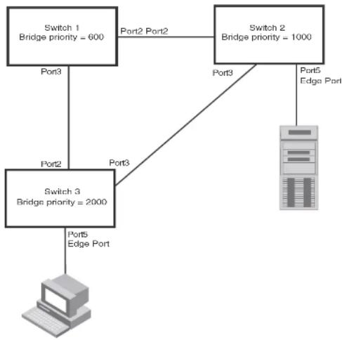
flowchart
graph TD
    A["Switch 1\nBridge priority = 600"] -->|Port2 Port2| B["Switch 2\nBridge priority = 1000"]
    A -->|Port3| C["Switch 3\nBridge priority = 2000"]
    B -->|Port3| C
    C -->|Port5 Edge Port| D["Computer"]
    B -->|Port3| E["Server"]
NOTE
Configuring shared media or non-point-to-point links as point-to-point links could lead to Layer 2 loops.
The topology in Figure 28 is an example of shared media that should not be configured as point-to-point links. In Figure 28, a port on a bridge communicates or is connected to at least two ports.
FIGURE 28 Example of shared media

flowchart
graph TD
    A["Power Input"] --> B["Output"]
    C["Power Output"] --> D["Output"]
    E["Power Outlet"] --> F["Output"]
Bridge port states
Ports roles can have one of the following states:
- Forwarding - 802.1W is allowing the port to send and receive all packets.
- Discarding - 802.1W has blocked data traffic on this port to prevent a loop. The device or VLAN can reach the root bridge using another port, whose state is forwarding. When a port is in this state, the port does not transmit or receive data frames, but the port does continue to receive RST BPDUs. This state corresponds to the listening and blocking states of 802.1D.
- Learning - 802.1W is allowing MAC entries to be added to the filtering database but does not permit forwarding of data frames. The device can learn the MAC addresses of frames that the port receives during this state and make corresponding entries in the MAC table.
Edge port and non-edge port states
As soon as a port is configured as an Edge port using the CLI, it goes into a forwarding state instantly (in less than 100 msec).
When the link to a port comes up and 802.1W detects that the port is an Edge port, that port instantly goes into a forwarding state.
If 802.1W detects that port as a non-edge port, the port state is changed as determined by the result of processing the received RST BPDU. The port state change occurs within four seconds of link up or after two hello timer expires on the port.
Changes to port roles and states
To achieve convergence in a topology, a port role and state changes as it receives and transmits new RST BPDUs. Changes in a port role and state constitute a topology change. Besides the superiority and inferiority of the RST BPDU, bridge-wide and per-port state machines are used to determine a port role as well as a port state. Port state machines also determine when port role and state changes occur.
State machines
The bridge uses the Port Role Selection state machine to determine if port role changes are required on the bridge. This state machine performs a computation when one of the following events occur:
- New information is received on any port on the bridge
• The timer expires for the current information on a port on the bridge
Each port uses the following state machines: - Port Information – This state machine keeps track of spanning-tree information currently used by the port. It records the origin of the information and ages out any information that was derived from an incoming BPDU.
- Port Role Transition – This state machine keeps track of the current port role and transitions the port to the appropriate role when required. It moves the Root port and the Designated port into forwarding states and moves the Alternate and Backup ports into discarding states.
In contrast to the 802.1D standard, the 802.1W standard does not have any bridge specific timers. All timers in the CLI are applied on a per-port basis, even though they are configured under bridge parameters.
802.1W state machines attempt to quickly place the ports into either a forwarding or discarding state. Root ports are quickly placed in forwarding state when both of the following events occur:
- It is assigned to be the Root port.
- It receives an RST BPDU with a proposal flag from a Designated port. The proposal flag is sent by ports with a Designated role when they are ready to move into a forwarding state.
When a the role of Root port is given to another port, the old Root port is instructed to reroot. The old Root port goes into a discarding state and negotiates with its peer port for a new role and a new state. A peer port is the port on the other bridge to which the port is connected. For example, in Figure 29, Port1 of Switch 200 is the peer port of Port2 of Switch 100.
A port with a Designated role is quickly placed into a forwarding state if one of the following occurs:
• The Designated port receives an RST BPDU that contains an agreement flag from a Root port
• The Designated port is an Edge port
However, a Designated port that is attached to an Alternate port or a Backup port must wait until the forward delay timer expires twice on that port while it is still in a Designated role, before it can proceed to the forwarding state.
Backup ports are quickly placed into discarding states.
Alternate ports are quickly placed into discarding states.
A port operating in 802.1W mode may enter a learning state to allow MAC entries to be added to the filtering database; however, this state is transient and lasts only a few milliseconds, if the port is operating in 802.1W mode and if the port meets the conditions for rapid transition.
Handshake mechanisms
To rapidly transition a Designated or Root port into a forwarding state, the Port Role Transition state machine uses handshake mechanisms to ensure loop free operations. It uses one type of handshake if no Root port has been assigned on a bridge, and another type if a Root port has already been assigned.
NOTE
Proposed will never be asserted if the port is connected on a shared media link.
In Figure 29, Port3/Switch 200 is elected as the Root port
FIGURE 29 Proposing and proposed stage

flowchart
graph TD
    A["Switch 100\nRoot Bridge"] -->|RST RPDU\nand with a\nProposal\nflag| B["Switch 200"]
    A -->|Port2\nDesignated port\nProposing| B
    B -->|Port2\nPort3| C["Switch 300\nSwitch 400"]
    B -->|Port1\nRoot port\nProposed| D["Switch 200"]
- Sync - Once the Root port is elected, it sets a sync signal on all the ports on the bridge. The
FIGURE 30 Sync stage
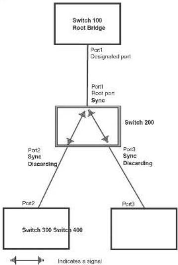
flowchart
graph TD
    A["Switch 100 Root Bridge"] -->|Port1 Designated port| B["Switch 200"]
    B -->|Port2 Sync Discarding| C["Switch 300 Switch 400"]
    B -->|Port3 Sync Discarding| D["Switch 300"]
    B -->|Port1 Root port Sync| E["Switch 200"]
    C --> F["Indicates a signal"]
    D --> F
- Synced – Once the Designated port changes into a discarding state, it asserts a synced signal. Immediately, Alternate ports and Backup ports are synced. The Root port monitors the synced signals from all the bridge ports. Once all bridge ports asserts a synced signal, the Root port asserts its own synced signal (Figure 31).
FIGURE 31 Synced stage

flowchart
graph TD
    A["Switch 100 Root Bridge"] -->|Port1 Designated port| B["Switch 200"]
    B -->|Port2 Synced Discarding| C["Switch 300"]
    B -->|Port3 Synced Discarding| D["Switch 400"]
    B -->|Indicates a signal| E["Output"]
- Agreed – The Root port sends back an RST BPDU containing an agreed flag to its peer Designated port and moves into the forwarding state. When the peer Designated port receives the RST BPDU, it rapidly transitions into a forwarding state.
FIGURE 32 Agree stage

flowchart
graph TD
    A["Switch 100 Root Bridge"] -->|Port1 Designated port Forwarding| B["Switch 200"]
    B -->|Port2 Synced Discarding| C["Switch 300"]
    B -->|Port3 Synced Discarding| D["Switch 400"]
    B -->|RST BPDU sent with an Agreed flag| A
    style A fill:#f9f,stroke:#333
    style B fill:#ccf,stroke:#333
    style C fill:#cff,stroke:#333
    style D fill:#ffc,stroke:#333
At this point, the handshake mechanism is complete between Switch 100, the root bridge, and Switch 200.
Switch 200 updates the information on the Switch 200 Designated ports (Port2 and Port3) and identifies the new root bridge. The Designated ports send RST RPDUs, containing proposal flags, to
FIGURE 33 Addition of a new root bridge

flowchart
graph TD
    A["Switch 100"] -->|Port1 Designated port| B["Switch 200"]
    A -->|Port2| C["Switch 60"]
    B -->|Port3| D["Switch 400"]
    B -->|Port4| E["Switch 300"]
    B -.->|Port5| F["Switch 200"]
    style A fill:#f9f,stroke:#333
    style B fill:#ccf,stroke:#333
    style C fill:#cfc,stroke:#333
    style D fill:#fcc,stroke:#333
    style E fill:#cff,stroke:#333
    style F fill:#ffc,stroke:#333
The handshake that occurs between Switch 60 and Switch 100 follows the one described in the previous section ("Handshake when no root port is elected" on page 234). The former root bridge becomes a non-root bridge and establishes a Root port (Figure 34).
However, since Switch 200 already had a Root port in a forwarding state, 802.1W uses the Proposing -> Proposed -> Sync and Reroot -> Sync and Rerooted -> Rerooted and Synced ->
FIGURE 34 New root bridge sending a proposal flag

flowchart
graph TD
    A["Switch 100"] -->|Port1| B["Switch 200"]
    A -->|Proposing| B
    B -->|Port2 Root port Forwarding| C["Switch 300"]
    B -->|Port3| D["Switch 400"]
    B -->|Port4 Designated port Proposed| E["Switch 60"]
    E -->|Port2 Handshake Completed Port2 Designated port| A
    E -->|Port4 Designated port Proposing| B
    B -->|Port1 Root port Forwarding| A
    B -->|Port2 Designated port Proposed| E
    style A fill:#f9f,stroke:#333
    style B fill:#ccf,stroke:#333
    style C fill:#cfc,stroke:#333
    style D fill:#fcc,stroke:#333
- Sync and Reroot - The Root port then asserts a sync and a reroot signal on all the ports on the bridge. The signal tells the ports that a new Root port has been assigned and they are to renegotiate their new roles and states. The other ports on the bridge assert their sync and reroot signals. Information about the old Root port is discarded from all ports. Designated ports change into discarding states (Figure 35).
FIGURE 35 Sync and reroot

flowchart
graph TD
    A["Switch 100"] -->|Port1| B["Switch 200"]
    A -->|Port2, Root port| C["Switch 60"]
    B -->|Port3 Sync Reroot Discarding| D["Switch 300"]
    B -->|Port4 Root port Sync Reroot Discarding| E["Switch 400"]
    B -->|Port5 Sync Reroot Discarding| F["Switch 200"]
    C -->|Port4 Designated port Proposing| B
    D --> G["Indicates a signal"]
    E --> H["Indicates a signal"]
    F --> I["Indicates a signal"]
    style A fill:#f9f,stroke:#333
    style B fill:#ccf,stroke:#333
    style C fill:#cfc,stroke:#333
    style D fill:#fcc,stroke:#333
    style E fill:#cff,stroke:#333
    style F fill:#ffc,stroke:#333
    style G fill:#fcc,stroke:#333
    style H fill:#fcc,stroke:#333
- Sync and Rerooted – When the ports on Switch 200 have completed the reroot phase, they assert their rerooted signals and continue to assert their sync signals as they continue in their discarding states. They also continue to negotiate their roles and states with their peer ports (Figure 36).
FIGURE 36 Sync and rerooted
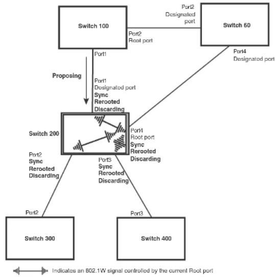
flowchart
graph TD
    A["Switch 100"] -->|Port1| B["Switch 200"]
    A -->|Proposing| B
    B -->|Port2 Sync Rerooted Discarding| C["Switch 300"]
    B -->|Port3 Sync Rerooted Discarding| D["Switch 400"]
    B -->|Port4 Root port Sync Rerooted Discarding| E["Switch 60"]
    E -->|Port2 Designated port| A
    B -->|Port1 Designated port Sync Rerooted Discarding| F["Switch 200"]
    style A fill:#f9f,stroke:#333
    style B fill:#ccf,stroke:#333
    style C fill:#cfc,stroke:#333
    style D fill:#fcc,stroke:#333
    style E fill:#ffc,stroke:#333
- Synced and Agree – When all the ports on the bridge assert their synced signals, the new Root port asserts its own synced signal and sends an RST BPDU to Port4/Switch 60 that contains an agreed flag (Figure 36). The Root port also moves into a forwarding state.
FIGURE 37 Rerooted, synced, and agreed
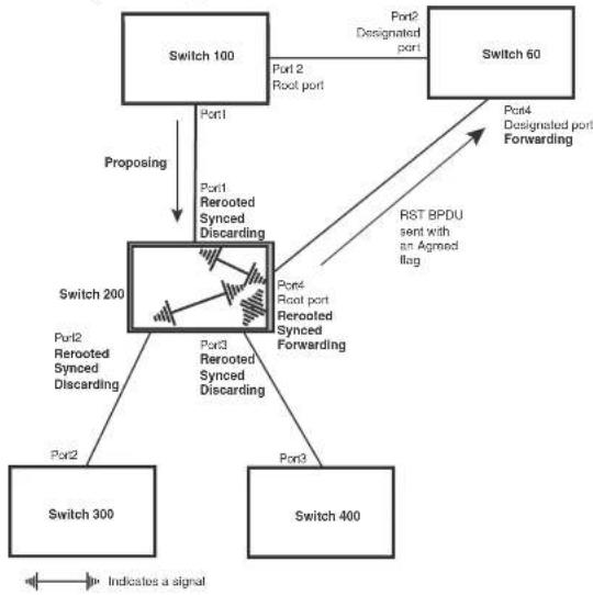
flowchart
graph TD
    A["Switch 100"] -->|Port1| B["Switch 200"]
    A -->|Port2\nRerooted Synced Discarding| B
    A -->|Port4\nRerooted Synced Forwarding| B
    B -->|Port3\nRerooted Synced Discarding| C["Switch 300"]
    B -->|Port4\nRerooted Synced Forwarding| D["Switch 400"]
    B -->|Port5\nRerooted Synced Discarding| E["Switch 60"]
    B -->|Port6\nRerooted Port Forwarding| F["Switch 60"]
    A -->|Port2\nRoot port| G["Switch 60"]
    B -->|Port1\nRerooted Synced Discarding| H["Switch 200"]
    B -->|Port2\nRerooted Synced Discarding| I["Switch 300"]
    B -->|Port3\nRerooted Synced Discarding| J["Switch 400"]
    B -->|Port4\nRerooted Port Forwarding| K["Switch 60"]
    style A fill:#f9f,stroke:#333
    style B fill:#ccf,stroke:#333
    style C fill:#cfc,stroke:#333
    style D fill:#fcc,stroke:#333
    style E fill:#cff,stroke:#333
    style F fill:#ffc,stroke:#333
    style G fill:#fcc,stroke:#333
    style H fill:#ffc,stroke:#333
    style I fill:#fcc,stroke:#333
    style J fill:#fcc,stroke:#333
    style K fill:#fcc,stroke:#333
The old Root port on Switch 200 becomes an Alternate Port (Figure 38). Other ports on that bridge are elected to appropriate roles.
The Designated port on Switch 60 goes into a forwarding state once it receives the RST BPDU with the agreed flag.
FIGURE 38 Handshake completed after election of new root port
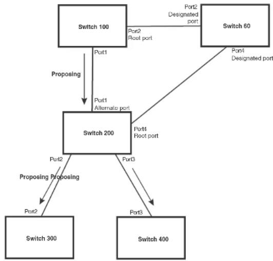
flowchart
graph TD
    A["Switch 100"] -->|Proposing| B["Switch 200"]
    B -->|Proposing Proposing| C["Switch 300"]
    B -->|Proposing Proposing| D["Switch 400"]
    B -->|Port1 Alternato port| E["Switch 200"]
    B -->|Port2 Root port| F["Switch 60"]
    F -->|Port1 Designated port| G["Switch 100"]
    F -->|Port2 Designated port| H["Switch 60"]
    B -->|Port3 Root port| I["Switch 200"]
    B -->|Port3 Root port| J["Switch 400"]
Recall that Switch 200 sent the agreed flag to Port4/Switch 60 and not to Port1/Switch 100 (the port that connects Switch 100 to Switch 200). Therefore, Port1/Switch 100 does not go into forwarding state instantly. It waits until two instances of the forward delay timer expires on the port before it goes into forwarding state.
At this point the handshake between the Switch 60 and Switch 200 is complete.
FIGURE 39 Convergence between two bridges
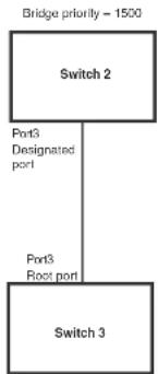
flowchart
graph TD
    A["Bridge priority - 1500"] --> B["Switch 2"]
    B --> C["Port3 Designated port"]
    B --> D["Port3 Root port"]
    E["Switch 3"] --> F["Switch 3"]
Bridge priority = 2000
At power up, all ports on Switch 2 and Switch 3 assume Designated port roles and are at discarding states before they receive any RST BPDU.
Port3/Switch 2, with a Designated role, transmits an RST BPDU with a proposal flag to Port3/Switch 3. A ports with a Designated role sends the proposal flag in its RST BPDU when they are ready to move to a forwarding state.
Port3/Switch 3, which starts with a role of Designated port, receives the RST BPDU and finds that it is superior to what it can transmit; therefore, Port3/Switch 3 assumes a new port role, that of a Root port. Port3/Switch 3 transmits an RST BPDU with an agreed flag back to Switch 2 and immediately goes into a forwarding state.
Port3/Switch 2 receives the RST BPDU from Port3/Switch 3 and immediately goes into a forwarding state.
FIGURE 40 Simple Layer 2 topology

flowchart
graph TD
    A["Switch 2"] -->|Port3 Designated port| B["Switch 1"]
    A -->|Port3 Alternate port| C["Switch 3"]
    B -->|Port4 Designated port| C
    B -->|Port5 Backup port| A
    A -->|Bridge priority = 1500| D["Switch 2"]
    B -->|Bridge priority = 1000| E["Switch 1"]
    C -->|Bridge priority = 2000| F["Switch 3"]
The point-to-point connections between the three bridges are as follows:
• Port2/Switch 1 and Port2/Switch 2
• Port4/Switch 1 and Port4/Switch 3
• Port3/Switch 2 and Port3/Switch 3
Ports 3 and 5 on Switch 1 are physically connected together.
At start up, the ports on Switch 1 assume Designated port roles, which are in discarding state. They begin sending RST BPDUs with proposal flags to move into a forwarding state.
When Port4/Switch 3 receives these RST BPDUs 802.1W algorithm determines that they are better than the RST BPDUs that were previously received on Port3/Switch 3. Port4/Switch 3 is now selected as Port port. This new assignment signals Port3/Switch 3 to begin entering the discarding
Now, Port3/Switch 3 is currently in a discarding state and is negotiating a port role. It received RST BPDUs from Port3/Switch 2. The 802.1W algorithm determines that the RST BPDUs Port3/Switch 3 received are superior to those it can transmit; however, they are not superior to those that are currently being received by the current Root port (Port4). Therefore, Port3 retains the role of Alternate port.
Ports 3/Switch 1 and Port5/Switch 1 are physically connected. Port5/Switch 1 received RST BPDUs that are superior to those received on Port3/Switch 1; therefore, Port5/Switch 1 is given the Backup port role while Port3 is given the Designated port role. Port3/Switch 1, does not go directly into a forwarding state. It waits until the forward delay time expires twice on that port before it can proceed to the forwarding state.
Once convergence is achieved, the active Layer 2 forwarding path converges as shown in Figure 41.
FIGURE 41 Active Layer 2 path
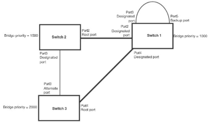
flowchart
graph TD
    A["Switch 2"] -->|Bridge priority = 1500| B["Switch 1"]
    A -->|Port3 Designated port| C["Switch 3"]
    A -->|Port2 Root port| D["Switch 1"]
    A -->|Port3 Alternative port| E["Switch 3"]
    B -->|Port4 Designated port| D
    B -->|Port5 Backup port| E
    C -->|Port4 Root port| E
    style A fill:#f9f,stroke:#333
    style B fill:#ccf,stroke:#333
    style C fill:#cfc,stroke:#333
    style D fill:#fcc,stroke:#333
    style E fill:#cff,stroke:#333
FIGURE 42 Link failure in the topology
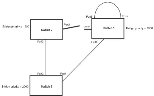
flowchart
graph TD
    A["Switch 1"] -->|Port3| B["Switch 2"]
    A -->|Port4| C["Switch 3"]
    B -->|Port3| D["Switch 3"]
    C -->|Port4| D
    E["Bridge priority = 1000"] --> A
    F["Bridge priority = 1500"] --> B
    G["Bridge priority = 2000"] --> C
    H["Bridge priority = 1000"] --> I["Port5"]
    J["Bridge priority = 1500"] --> K["Port2"]
    L["Bridge priority = 2000"] --> M["Port3"]
Switch 1 sets its Port2 into a discarding state.
At the same time, Switch 2 assumes the role of a root bridge since its root port failed and it has no operational Alternate port. Port3/Switch 2, which currently has a Designated port role, sends an RST BPDU to Switch 3. The RST BPDU contains a proposal flag and a bridge ID of Switch 2 as its root bridge ID.
When Port3/Switch 3 receives the RST BPDUs, 802.1W algorithm determines that they are inferior to those that the port can transmit. Therefore, Port3/Switch 3 is given a new role, that of a Designated port. Port3/Switch 3 then sends an RST BPDU with a proposal flag to Switch 2, along with the new role information. However, the root bridge ID transmitted in the RST BPDU is still Switch 1.
When Port2/Switch 2 receives the RST BPDUs, 802.1W algorithm determines that the RST BPDUs the port received are better than those received on Port3/Switch 3; therefore, Port2/Switch 2 is given the role of a Root port. All the ports on Switch 2 are informed that a new Root port has been assigned which then signals all the ports to synchronize their roles and states. Port3/Switch 2, which was the previous Root port, enters a discarding state and negotiates with other ports on the bridge to establish its new role and state, until it finally assumes the role of a Designated port.
Next, the following happens:
- Port3/Switch 2, the Designated port, sends an RST BPDU, with a proposal flag to Port3/Switch 3.
- Port2/Switch 2 also sends an RST BPDU with an agreed flag to Port2/Switch 1 and then places itself into a forwarding state.
When Port2/Switch 1 receives the RST BPDU with an agreed flag sent by Port2/Switch 2, it puts that port into a forwarding state. The topology is now fully converged.
When Port3/Switch 3 receives the RST BPDU that Port3/Switch 2 sent, 802.1W algorithm determines that these RST BPDUs are superior to those that Port3/Switch 3 can transmit. Therefore, Port3/Switch 3 is given a new role, that of an Alternate port. Port3/Switch 3 immediately enters a discarding state.
Now Port3/Switch 2 does not go into a forwarding state instantly like the Root port. It waits until the forward delay timer expires twice on that port while it is still in a Designated role, before it can proceed to the forwarding state. The wait, however, does not cause a denial of service, since the essential connectivity in the topology has already been established.
When fully restored, the topology is the same as that shown on Figure 40.
Convergence in a complex 802.1W topology
The following is an example of a complex 802.1W topology.
FIGURE 43 Complex 802.1W topology

flowchart
graph TD
    Switch1["Switch 1"] -->|Port2| Switch2["Switch 2"]
    Switch1 -->|Port3| Switch3["Switch 3"]
    Switch2 -->|Port4| Switch4["Switch 4"]
    Switch2 -->|Port5| Switch5["Switch 5"]
    Switch2 -->|Port6| Switch6["Switch 6"]
    Switch2 -->|Port7| Switch1
    Switch2 -->|Port8| Switch2
    Switch2 -->|Port9| Switch2
    Switch3 -->|Port1| Switch4
    Switch3 -->|Port2| Switch1
    Switch3 -->|Port3| Switch2
    Switch4 -->|Port4| Switch3
    Switch4 -->|Port5 Ports| Switch5
    Switch4 -->|Port6 Ports| Switch6
    Switch6 -->|Port7 Port8| Switch2
    Switch6 -->|Port8 Port9| Switch2
    Switch6 -->|Port9 Port10| Switch1
    Switch6 -->|Port10 Port11| Switch1
    Switch6 -->|Port11 Port12| Switch2
    Switch6 -->|Port12 Port13| Switch3
    Switch6 -->|Port13 Port14| Switch4
    Switch6 -->|Port14 Port15| Switch5
    Switch6 -->|Port15 Port16| Switch6
    Switch6 -->|Port16 Port17| Switch5
    Switch6 -->|Port17 Port18| Switch4
    Switch6 -->|Port18 Port19| Switch5
    Switch6 -->|Port19 Port20| Switch5
    Switch6 -->|Port20 Port21| Switch5
    Switch6 -->|Port21 Port22| Switch5
    Switch6 -->|Port22 Port23| Switch5
    Switch6 -->|Port23 Port24| Switch5
    Switch6 -->|Port24 Port25| Switch5
    Switch6 -->|Port25 Port26| Switch5
    Switch6 -->|Port26 Port27| Switch5
    Switch6 -->|Port27 Port28| Switch5
    Switch6 -->|Port28 Port29| Switch5
    Switch6 -->|Port29 Port30| Switch5
    Switch6 -->|Port30 Port31| Switch5
    Switch6 -->|Port31 Port32| Switch5
    Switch6 -->|Port32 Port33| Switch5
    Switch6 -->|Port33 Port34| Switch5
    Switch6 -->|Port34 Port35| Switch5
    Switch6 -->|Port35 Port36| Switch5
    Switch6 -->|Port36 Port37| Switch5
    Switch6 -->|Port37 Port38| Switch5
    Switch6 -->|Port38 Port39| Switch5
    Switch6 -->|Port39 Port40| Switch5
    Switch6 -->|Port40 Port41| Switch5
    Switch6 -->|Port41 Port42| Switch5
    Switch6 -->|Port42 Port43| Switch5
    Switch6 -->|Port43 Port44| Switch5
    Switch6 -->|Port44 Port45| Switch5
    Switch6 -->|Port45 Port46| Switch5
    Switch6 -->|Port46 Port47| Switch5
    Switch6 -->|Port47 Port48| Switch5
    Switch6 -->|Port48 Port49| Switch5
    Switch6 -->|Port49 Port50| Switch5
In Figure 43, Switch 5 is selected as the root bridge since it is the bridge with the highest priority. Lines in the figure show the point-to-point connection to the bridges in the topology.
Switch 5 sends an RST BPDU that contains a proposal flag to Port5/Switch 2. When handshakes are completed in Switch 5, Port5/Switch 2 is selected as the Root port on Switch 2. All other ports on Switch 2 are given Designated port role with discarding states.
Next Switch 2 sends RST BPDUs with a proposal flag to Port3/Switch 4. Port3 becomes the Root port for the bridge; all other ports are given a Designated port role with discarding states.
Port3/Switch 4 sends an RST BPDU with an agreed flag to Switch 2 to confirm that it is the new Root port. The port then goes into a forwarding state.
Now Port4/Switch 4 receives an RST BPDU that is superior to what it can transmit. The port is then given an Alternate port role, and remains in discarding state.
Likewise, Port5/Switch 4 receives an RST BPDU that is superior to what it can transmit. The port is also given an Alternate port role, and remains in discarding state.
Port2/Switch 2 transmits an RST BPDU with a proposal flag to Port2/Switch 1, Port2/Switch 1 becomes the Root port. All other ports on Switch 1 are given Designated port roles with discarding states.
Port2/Switch 1 sends an RST BPDU with an agreed flag to Port2/Switch 2 and Port2/Switch 1 goes into a forwarding state.
Port3/Switch 1 receives an RST BPDUs that is inferior to what it can transmit; therefore, the port retains its Designated port role and goes into forwarding state only after the forward delay timer expires twice on that port while it is still in a Designated role.
Port3/Switch 2 sends an RST BPDU to Port3/Switch 3 that contains a proposal flag. Port3/Switch 3 becomes the Root port, while all other ports on Switch 3 are given Designated port roles and go into discarding states. Port3/Switch 3 sends an RST BPDU with an agreed flag to Port3/Switch 2 and Port3/Switch 3 goes into a forwarding state.
Now, Port2/Switch 3 receives an RST BPDUs that is superior to what it can transmit so that port is given an Alternate port state.
Port4/Switch 3 receives an RST BPDU that is inferior to what it can transmit; therefore, the port retains its Designated port role.
Ports on all the bridges in the topology with Designated port roles that received RST BPDUs with agreed flags go into forwarding states instantly. However, Designated ports that did not receive RST BPDUs with agreed flags must wait until the forward delay timer expires twice on those port. Only then will these port move into forwarding states.
The entire 802.1W topology converges in less than 300 msec and the essential connectivity is
FIGURE 44 Active Layer 2 path in complex topology
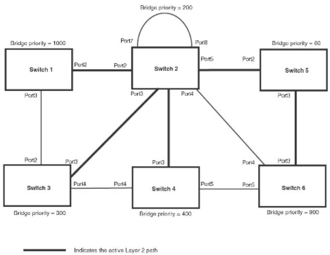
flowchart
graph TD
    Switch1["Switch 1"] -->|Port3| Switch2["Switch 2"]
    Switch2 -->|Port2| Switch1
    Switch2 -->|Port7| Switch2
    Switch2 -->|Port8| Switch5["Switch 5"]
    Switch2 -->|Port4| Switch4["Switch 4"]
    Switch4 -->|Port5| Switch6["Switch 6"]
    Switch4 -->|Port3| Switch3["Switch 3"]
    Switch3 -->|Port2| Switch1
    Switch3 -->|Port3| Switch2
    Switch2 -->|Port5| Switch5
    Switch2 -->|Port2| Switch5
    Switch2 -->|Port3| Switch4
    Switch2 -->|Port4| Switch3
    Switch2 -->|Port5| Switch6
    Switch2 -->|Port8| Switch5
    Switch2 -->|Port3| Switch4
    Switch2 -->|Port4| Switch3
    Switch2 -->|Port5| Switch6
    Switch2 -->|Port8| Switch5
    Switch2 -->|Port3| Switch3
    Switch2 -->|Port4| Switch4
    Switch2 -->|Port5| Switch6
    Switch2 -->|Port8| Switch5
    Switch2 -->|Port3| Switch3
    Switch2 -->|Port4| Switch4
    Switch2 -->|Port5| Switch6
    Switch2 -->|Port8| Switch5
    Switch2 -->|Port3| Switch3
    Switch2 -->|Port4| Switch4
    Switch2 -->|Port5| Switch6

    note right of Switch2: Bridge priority = 200
    note right of Switch2: Bridge priority = 60
    note right of Switch3: Bridge priority = 300
    note right of Switch4: Bridge priority = 400
    note right of Switch6: Bridge priority = 900
Propagation of topology change
The Topology Change state machine generates and propagates the topology change notification messages on each port. When a Root port or a Designated port goes into a forwarding state, the Topology Change state machine on those ports send a topology change notice (TCN) to all the bridges in the topology to propagate the topology change.
FIGURE 45 Beginning of topology change notice
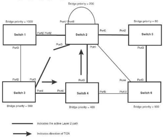
flowchart
graph TD
    A["Switch 1"] -->|Port2 Port2| B["Switch 2"]
    B -->|Port5 Port2| C["Switch 5"]
    B -->|Port3 Port3| D["Switch 3"]
    D -->|Port4 Port4| E["Switch 4"]
    E -->|Port5 Port5| F["Switch 6"]
    F -->|Port3 Port3| C
    B -->|Port7 Port8| G["Bridge priority = 200"]
    D -->|Port4 Port4| H["Bridge priority = 300"]
    E -->|Port3 Port3| I["Bridge priority = 400"]
    F -->|Port4 Port4| J["Bridge priority = 500"]
    style A fill:#f9f,stroke:#333
    style B fill:#ccf,stroke:#333
    style C fill:#cfc,stroke:#333
    style D fill:#fcc,stroke:#333
    style E fill:#cff,stroke:#333
    style F fill:#ffc,stroke:#333
    style G fill:#fcc,stroke:#333
    style H fill:#cff,stroke:#333
    style I fill:#fcc,stroke:#333
    style J fill:#cff,stroke:#333
Switch 2 then starts the TCN timer on the Designated ports and sends RST BPDUs that contain the TCN as follows (Figure 46):
- Port5/Switch 2 sends the TCN to Port2/Switch 5
FIGURE 46 Sending TCN to bridges connected to Switch 2
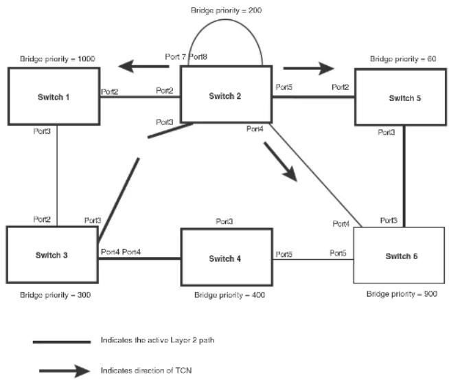
flowchart
graph TD
    A["Switch 1"] -->|Port2| B["Switch 2"]
    B -->|Port5| C["Switch 5"]
    B -->|Port4| D["Switch 6"]
    D -->|Port3| E["Switch 3"]
    E -->|Port4 Port4| F["Switch 4"]
    F -->|Port5| G["Switch 6"]
    G -->|Port3| H["Switch 5"]
    H -->|Port2| I["Switch 2"]
    I -->|Port7 Port8| J["Switch 2"]
    J -->|Port7 Port8| K["Switch 1"]
    style A fill:#f9f,stroke:#333
    style B fill:#ccf,stroke:#333
    style C fill:#cfc,stroke:#333
    style D fill:#fcc,stroke:#333
    style E fill:#cff,stroke:#333
    style F fill:#ffc,stroke:#333
    style G fill:#fcc,stroke:#333
    style H fill:#cfc,stroke:#333
    style I fill:#fcc,stroke:#333
    style J fill:#cfc,stroke:#333
    style K fill:#fcc,stroke:#333
Then Switch 1, Switch 5, and Switch 6 send RST BPDUs that contain the TCN to Switch 3 and Switch 4 to complete the TCN propagation (Figure 47).
FIGURE 47 Completing the TCN propagation

flowchart
graph TD
    A["Switch 1\nBridge priority = 1000"] -->|Port3| B["Switch 3\nBridge priority = 300"]
    B -->|Port4 Port4| C["Switch 4\nBridge priority = 400"]
    C -->|Port5 Port5| D["Switch 5\nBridge priority = 900"]
    D -->|Port6 Port6| E["Switch 2\nBridge priority = 200"]
    E -->|Port7 Port8| F["Switch 2\nBridge priority = 200"]
    F -->|Port8 Port8| E
    E -->|Port3 Port3| B
    F -->|Port4 Port4| C
    F -->|Port5 Port5| D
    style A fill:#f9f,stroke:#333
    style B fill:#f9f,stroke:#333
    style C fill:#f9f,stroke:#333
    style D fill:#f9f,stroke:#333
    style E fill:#f9f,stroke:#333
    linkStyle 0 stroke:#000,stroke-width:2px
    linkStyle 1 stroke:#000,stroke-width:2px
    linkStyle 2 stroke:#000,stroke-width:2px
    linkStyle 3 stroke:#000,stroke-width:2px
    linkStyle 4 stroke:#000,stroke-width:2px
    linkStyle 5 stroke:#000,stroke-width:2px
    linkStyle 6 stroke:#000,stroke-width:2px
    linkStyle 7 stroke:#000,stroke-width:2px
    linkStyle 8 stroke:#000,stroke-width:2px
    linkStyle 9 stroke:#000,stroke-width:2px
    linkStyle 10 stroke:#000,stroke-width:2px
    linkStyle 11 stroke:#000,stroke-width:2px
    linkStyle 12 stroke:#000,stroke-width:2px
    linkStyle 13 stroke:#000,stroke-width:2px
    linkStyle 14 stroke:#000,stroke-width:2px
    linkStyle 15 stroke:#000,stroke-width:2px
    linkStyle 16 stroke:#000,stroke-width:2px
    linkStyle 17 stroke:#000,stroke-width:2px
    linkStyle 18 stroke:#000,stroke-width:2px
    linkStyle 19 stroke:#000,stroke-width:2px
    linkStyle 20 stroke:#000,stroke-width:2px
    linkStyle 21 stroke:#000,stroke-width:2px
    linkStyle 22 stroke:#000,stroke-width:2px
    linkStyle 23 stroke:#000,stroke-width:2px
    linkStyle 24 stroke:#000,stroke-width:2px
    linkStyle 25 stroke:#000,stroke-width:2px
    linkStyle 26 stroke:#000,stroke-width:2px
    linkStyle 27 stroke:#000,stroke-width:2px
    linkStyle 28 stroke:#000,stroke-width:2px
    linkStyle 29 stroke:#000,stroke-width:2px
    linkStyle 30 stroke:#000,stroke-width:2px
    linkStyle 31 stroke:#000,stroke-width:2px
    linkStyle 32 stroke:#000,stroke-width:2px
    linkStyle 33 stroke:#000,stroke-width:2px
    linkStyle 34 stroke:#000,stroke-width:2px
    linkStyle 35 stroke:#000,stroke-width:2px
    linkStyle 36 stroke:#000,stroke-width:2px
    linkStyle 37 stroke:#000,stroke-width:2px
    linkStyle 38 stroke:#000,stroke-width:2px
    linkStyle 39 stroke:#000,stroke-width:2px
    linkStyle 40 stroke:#f9f,stroke-width:2px
    linkStyle 41 stroke:#f9f,stroke-width:2px
    linkStyle 42 stroke:#f9f,stroke-width:2px
    linkStyle 43 stroke:#f9f,stroke-width:2px
    linkStyle 44 stroke:#f9f,stroke-width:2px
    linkStyle 45 stroke:#f9f,stroke-width:2px
    linkStyle 46 stroke:#f9f,stroke-width:2px
    linkStyle 47 stroke:#f9f,stroke-width:2px
    linkStyle 48 stroke:#f9f,stroke-width:2px
    linkStyle 49 stroke:#f9f,stroke-width:2px
    linkStyle 50 stroke:#f9f,stroke-width:2px
Compatibility of 802.1W with 802.1D
802.1W-enabled bridges are backward compatible with IEEE 802.1D bridges. This compatibility is managed on a per-port basis by the Port Migration state machine. However, intermixing the two types of bridges in the network topology is not advisable if you want to take advantage of the rapid
FIGURE 48 802.1W bridges with an 802.1D bridge
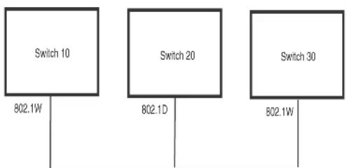
flowchart
graph TD
    A["Switch 10\n802.1W"] --> B["Switch 20\n802.1D"]
    C["Switch 30\n802.1W"] --> D["Switch 30\n802.1W"]
Once Switch 20 is removed from the LAN, Switch 10 and Switch 30 receive and transmit BPDUs in the STP format to and from each other. This state will continue until the administrator enables the force-migration-check command to force the bridge to send RSTP BPDU during a migrate time period. If ports on the bridges continue to hear only STP BPDUs after this migrate time period, those ports will return to sending STP BPDUs. However, when the ports receive RST BPDUs during the migrate time period, the ports begin sending RST BPDUs. The migrate time period is non-configurable. It has a value of three seconds.
NOTE
The IEEE standards state that 802.1W bridges need to interoperate with 802.1D bridges. IEEE standards set the path cost of 802.1W bridges to be between 1 and 200,000,000; whereas path cost of 802.1D bridges are set between 1 and 65,535. In order for the two bridge types to be able to interoperate in the same topology, the administrator needs to configure the bridge path cost appropriately. Path costs for either 802.1W bridges or 802.1D bridges need to be changed; in most cases, path costs for 802.1W bridges need to be changed.
Configuring 802.1W parameters on a Dell PowerConnect device
Enabling or disabling 802.1W in a port-based VLAN
Use the following procedure to disable or enable 802.1W on a device on which you have configured a port-based VLAN. Changing the 802.1W state in a VLAN affects only that VLAN.
To enable 802.1W for all ports in a port-based VLAN, enter commands such as the following.
PowerConnect(config)#vlan 10
PowerConnect(config vlan 10)#spanning tree 802-1w
Syntax: [no] spanning-tree 802-1w
Note regarding pasting 802.1W settings into the running configuration
If you paste 802.1W settings into the running configuration, and the pasted configuration includes ports that are already up, the ports will initially operate in STP legacy mode before operating in 802.1W RSTP mode. For example, the following pasted configuration will cause ports e 1 and e 2 to temporarily operate in STP legacy mode, because these ports are already up and running.
conf t.
vlan 120
tag e 1 to e 2
spanning-tree 802-1w
spanning-tree 802-1w priority 1001
end
To avoid this issue, 802.1W commands/settings that are pasted into the configuration should be in the following order.
-
Ports that are not yet connected
-
802.1W RSTP settings
-
Ports that are already up
Example
conf t.
vlan 120
untag e 3
spanning-tree 802-1w
spanning-tree 802-1w priority 1001
tag e 1 to 2
Once 802.1W is enabled on a port, it can be disabled on individual ports. 802.1W that have been disabled on individual ports can then be enabled as required.
NOTE
If you change the 802.1W state of the primary port in a trunk group, the change affects all ports in that trunk group.
To disable or enable 802.1W on an individual port, enter commands such as the following.
PowerConnect(config)#interface e 1
PowerConnect(config-if-ol000-1)#no spanning-tree
Syntax: [no] spanning-tree
Changing 802.1W bridge parameters
When you make changes to 802.1W bridge parameters, the changes are applied to individual ports on the bridge. To change 802.1W bridge parameters, use the following methods.
To designate a priority for a bridge, enter a command such as the following.
PowerConnect{config}#spanning-tree 802-1w priority 10
The command in this example changes the priority on a device on which you have not configured port-based VLANs. The change applies to the default VLAN. If you have configured a port-based VLAN on the device, you can configure the parameters only at the configuration level for individual VLANs. Enter commands such as the following.
PowerConnect(config)#vlan 20
PowerConnect(config-vlan-20)4spanning-tree 802-lw priority 0
To make this change in the default VLAN, enter the following commands.
PowerConnect(config)#vlan 1
PowerConnect(config-vlan-1)#spanning-tree 802-lw priority 0
Syntax: spanning-tree 802-1w [forward-delay
The forward-delay
The priority
You can specify some or all of these parameters on the same command line. If you specify more than one parameter, you must specify them in the order shown above, from left to right.
Changing port parameters
The 802.1W port commands can be enabled on individual ports or on multiple ports, such as all ports that belong to a VLAN.
The 802.1W port parameters are preconfigured with default values. If the default parameters meet your network requirements, no other action is required.
You can change the following 802.1W port parameters using the following method.
PowerConnect(config)#vlan 10
PowerConnect(config-vlan-10)↑spanning-tree 802-lw ethernet 5 path-cost 15 priority 64
Syntax: spanning-tree 802-1w ethernet
The ethernet
• PowerConnect B-Series FCX stackable switches -
The path-cost
TABLE 52 Recommended path cost values of 802.1W
| Link speed Recommended (Default) 802.1Wpath cost values | Recommended 802.1W patch cost range |
| Less than 100 kilobits per second 200,000,000 20,000,000 - 200,000,000 | |
| 1 Mugabit per second 20,000,000 2,000,000 - 200,000,000 | |
| 10 Mugabit per second 2,000,000 200,000,000 - 200,000,000 | |
Set the admin-pt2pt-mac to enabled or disabled. If set to enabled, then a port is connected to another port through a point-to-point link. The point-to-point link increases the speed of convergence. This parameter, however, does not auto-detect whether or not the link is a physical point-to-point link.
The force-migration-check parameter forces the specified port to sent one RST BPDU. If only STP BPDUs are received in response to the sent RST BPDU, then the port will go return to sending STP BPDUs.
Example
Suppose you want to enable 802.1W on a system with no active port-based VLANs and change the hello-time from the default value of 2 to 8 seconds. Additionally, suppose you want to change the path and priority costs for port 5 only. To do so, enter the following commands.
PowerConnect(config)#spanning-tree 802-lw hello-time 8 PowerConnect(config)#spanning-tree 802-lw ethernet 5 path-cost 15 priority 64
Displaying information about 802-1W
To display a summary of 802-1W, use the following command.
PowerConnect#show 802-1w
--- VLAN 1 [ STP Instance owned by VLAN 1 ] ----
VLAN 1 B20U cam_Indox is 2 and the ICC and DMA master Arc(HEX) 0 1 2 3
Bridge IEEE 802.1W Parameters:
Bridge Bridge Bridge Bridge Force tx
Identifier MaxAge Hello FwdDly Version Hold
hex sec sec sec cnl
800000e080541700 20 2 15 Default 3
RootBridge
Identifier
hex
RootPath
Cost
800000c0804c9c00
200000
DesignatedBri-
age Identifier
hex
Root
Port
1
Max
Age
sec
20
Fwd
Dly
sec
Hol
lo
sec
2
15
2
Port IEEE 802.1W Parameters:
<--- Config Params ->|<---- Current state
Port Pri PortPath POP Edge Rule State Designs- Designated
TABLE 53 CLI display of 802.1W summary (Continued)
| This field... | Displays... |
| Bridge IEEE 802.1W parameters | |
| Bridge Identifier The ID of the bridge. | |
| Bridge Max Age The configured max age for this bridge. The default is 20. | |
| Bridge Hello The configured hello time for this bridge.The default is 2. | |
| Bridge FwdDly The configured forward delay time for this bridge. The default is 15. | |
| Force-Version The configured force version value. One of the following value is displayed:• 0 - The bridge has been forced to operate in an STP compatibility mode.• 2 - The bridge has been forced to operate in an 802.1W mode.(This is the default.) | |
| txHoldCnt The number of BPDUs that can be transmitted per Hello Interval. The default is 3. | |
| Root Bridge Identifier ID of the Root bridge that is associated with this bridge | |
| Root Path Cost The cost to reach the root bridge from this bridge. If the bridge is the root bridge, then this parameter shows a value of zero. | |
| Designated Bridge Identifier The bridge from where the root information was received.It can be from the root bridge itself, but it could also be from another bridge. | |
| Root Port The port on which the root information was received. This is the port that is connected to the Designated Bridge. | |
| Max Age | The max age is derived from the Root port. An 802.1W-enabled bridge uses this value, along with the hello and message age parameters to compute the effective age of an RST BPDU.The message age parameter is generated by the Designated port and transmitted in the RST BPDU. RST BPDUs transmitted by a Designated port of the root bridge contains a message value of zero.Effective age is the amount of time the Root port. Alternate port, or Backup port retains the information it received from its poor Designated port. Effective age is reset every time a port receives an RST BPDU from |
| Hello The hello value derived from the Root port. It is the number of seconds between two Hello packets. | |
| Port IEEE 802.1W parameters | |
| Port Num The port number shown in a slot#/port# format. | |
| Pri The configured priority of the port. The default is 125 or 0x80. | |
| Port Path Cost The configured path cost on a link connected to this port. | |
| P2P Mac Indicates if the point-to-point-mac parameter is configured to be a point-to-point link:• T - The link is configured as a point-to-point link.• F - The link is not configured as a point-to-point link. This is the default. | |
| Edge port indicates if the port is configured as an operational Edge port:• T - The port is configured as an Edge port.• F - The port is not configured as an Edge port. This is the default. | |
| Role The current role of the port:• Root• Designated• Alternate• Backup• DisabledRefer to “Bridges and bridge port roles” on page 228 for definitions of the roles. | |
| State The port current 802.1W state. A port can have one of the following states:• Forwarding• Discarding• Learning• DisabledRefer to “Bridge port states” on page 232 and “Edge port and non-edge port states” on page 233. | |
PowerConnect#show 802-1w detail
VLAN 1 - MULTIPLE SPANNING TREE (MSTP - IEEE 802.1W) ACTIVE
BridgeId 800000e080541700, forceVersion 2, txHoldCount 3
Port 1 - Role: ROOT - State: FORWARDING
PathCost 200000, Priority 128, AdminOperEdge F, AdminPt2PtMac F
DesignatedPriority - Root: 0x800000e0804c9c00, Bridge: 0x800000e080541700
ActiveTimers - rrWhile 4 rcvdInfoWhile 4
MachineStates - PIM: CURRENT, PRT: ROOT_PORT, PST: FORWARDING
TCM: ACTIVE, PPM: SENDING_STP, PTX: TRANSMIT_IDLE
Received - RST EPDUs 0, Config EPDUs 1017, TCN EPDUs 0
Port 2 - Role: DESIGNATED - State: FORWARDING
PathCost 200000, Priority 128, AdminOperEdge F, AdminPt2PtMac F
DesignatedPriority - Root: 0x800000e0804c9c00, Bridge: 0x800000e080541700
ActiveTimers - helloworld
MachineStates - PIM: CURRENT, PRT: DESIGNATED_PORT, PST: FORWARDING
TCM: ACTIVE, PPM: SENDING_RSTP, PTX: TRANSMIT_IDLE
Received - RST BPDUs 0, Config BPDUs 0, TCN BPDUs 0
Syntax: show 802-1w detail [vlan
The vlan
The show 802.1W command shows the following information.
TABLE 54 CLI display of show spanning-tree 802.1W
This field... Displays...
VLAN ID ID of the VLAN that owns the instance of 802.1W and whether or not it is
active.
Bridge ID ID of the bridge.
forceVersion the configured version of the bridge:
- 0 - The bridge has been forced to operate in an STP compatible
mode.
• 2 - The bridge has been forced to operate in an 802.1W mode.
TABLE 54 CLI display of show spanning-tree 802.1W (Continued)
| This field... Displays... |
| State The port current 802.1W state. A port can have one of the following states:ForwardingDiscardingLearningDisabledRefer to "Bridge port statics" on page 232 and "Edge port and non-edge port states" on page 233. |
| Path Cost The configured path cost on a link connected to this port. |
| Priority The configured priority of the port. The default is 128 or 0x80. |
| AdminOperEdge Indicates if the port is an operational Edge port. Edge ports may either be auto-detected or configured (forced) to be Edge ports using the CLI:T - The port is and Edge port.F - The port is not an Edge port. This is the default. |
| AdminP2PMac Indicates if the point-to-point-mac parameter is configured to be a point-to-point link:T - The link is a point-to-point linkF - The link is not a point-to-point link. This is the default. |
| DesignatedPriority Shows the following:Root - Shows the ID of the root bridge for this bridge.Bridge - Shows the ID of the Designated bridge that is associated with this port. |
| ActiveTimers Shows what timers are currently active on this port and the number of seconds they have before they expire:rrWhile - Recent root timer. A non-zero value means that the port has recently been a Root port.rcvdlinfoWhile - Received information timer. Shows the time remaining before the information held by this port expires (ages out). This timer is initialized with the effective ago parameter.(Refer to "Max Age" on page 261.)rbWhile - Recent backup timer. A non-zero value means that the |
| Machine States The current states of the various state machines on the port:PIM - State of the Port Information state machine.PRT - State of the Port Role Transition state machine.PST - State of the Port State Transition state machine.TCM - State of the Topology Change state machine.PPM - State of the Port Protocol Migration.PTX - State of the Port Transmit state machine.Refer to the section “State machines” on page 233 for details on state machines. |
| Received Shows the number of BPDU typos the port has received:RST BPDU - BPDU in 802.1W format.Config BPDU - Legacy configuration BPDU (802.1D format).TCN BPDU - Legacy topology change BPDU (802.1D format). |
802.1W Draft 3
As an alternative to full 802.1W, you can configure 802.1W Draft 3. 802.1W Draft 3 provides a subset of the RSTP capabilities described in the 802.1W STP specification.
802.1W Draft 3 support is disabled by default. When the feature is enabled, if a root port on a Dell PowerConnect device that is not the root bridge becomes unavailable, the device can automatically Switch over to an alternate root port, without reconvergence delays. 802.1W Draft 3 does not apply to the root bridge, since all the root bridge ports are always in the forwarding state.
Figure 49 shows an example of an optimal STP topology. In this topology, all the non-root bridges have at least two paths to the root bridge (Switch 1 in this example). One of the paths is through the root port. The other path is a backup and is through the alternate port. While the root port is in the forwarding state, the alternate port is in the blocking state.
FIGURE 49 802.1W Draft 3 RSTP ready for failover

flowchart
graph TD
    A["Switch 1"] -->|Port1/2 FWD| B["Switch 2"]
    A -->|Port1/4 FWD| B
    A -->|Port3/3 FWD| B
    A -->|Port3/4 BLK| B
    B -->|Port2/2 FWD| A
    B -->|Port2/4 FWD| A
    B -->|Port4/3 BLK| A
    B -->|Port4/4 FWD| A
    A -->|Port1/3 FWD| B
    B -->|Bridge priority = 4\nRoot port = 2/2\nAlternate = 2/3, 2/4\nRiding priority = 8]
    style A fill:#f9f,stroke:#333
    style B fill:#ccf,stroke:#333
FIGURE 50 802.1W Draft 3 RSTP failover to alternate root port

flowchart
graph TD
    A["Switch 1"] -->|Port 1/2 FWD| B["Switch 2"]
    A -->|Port 1/4 FWD| C["Switch 3"]
    A -->|Port 2/2 FWD| B
    A -->|Port 2/4 FWD| C
    B -->|Port 2/3 FWD| D["Switch 4"]
    B -->|Port 4/3 BLK| D
    C -->|Port 3/3 unavailable| D
    E["Switch 3"] -->|Port 1/3 DISABLED| A
    F["Switch 1"] -->|Port 1/3 FWD| A
    G["Switch 2"] -->|Port 2/3 FWD| B
    H["Switch 3"] -->|Port 3/4 FWD| C
    I["Switch 4"] -->|Port 4/4 FWD| B
    J["Switch 1"] -->|Bridge priority = 2\nRoot port = 2/2\nAlternate = 2/3, 2/4| B
    K["Switch 3"] -->|Bridge priority = 8\nRoot port = 3/4| C
    L["Switch 4"] -->|Bridge priority = 8\nRoot port = 4/4\nAlternate = 4/3| D
    M["Switch 1"] -->|X| N["Switch 3"]
    style A fill:#f9f,stroke:#333
    style B fill:#f9f,stroke:#333
    style C fill:#f9f,stroke:#333
    style D fill:#f9f,stroke:#333
    style E fill:#f9f,stroke:#333
    style F fill:#f9f,stroke:#333
    style G fill:#f9f,stroke:#333
    style H fill:#f9f,stroke:#333
    style I fill:#f9f,stroke:#333
    style J fill:#f9f,stroke:#333
    style K fill:#f9f,stroke:#333
    style L fill:#f9f,stroke:#333
In this example, port 3/3 on Switch 3 has become unavailable. In standard STP (802.1D), if the
Once a failover occurs, the Switch no longer has an alternate root port. If the port that was an alternate port but became the root port fails, standard STP is used to reconverge with the network. You can minimize the reconvergence delay in this case by setting the forwarding delay on the root bridge to a lower value. For example, if the forwarding delay is set to 15 seconds (the default), change the forwarding delay to a value from 3 - 10 seconds.
During failover, 802.1W Draft 3 flushes the MAC addresses leaned on the unavailable root port, selects the alternate port as the new root port, and places that port in the forwarding state. If traffic is flowing in both directions on the new root port, addresses are flushed (moved) in the rest of the spanning tree automatically.
Reconvergence time
Spanning tree reconvergence using 802.1W Draft 3 can occur within one second.
After the spanning tree reconverges following the topology change, traffic also must reconverge on all the bridges attached to the spanning tree. This is true regardless of whether 802.1W Draft 3 or standard STP is used to reconverge the spanning tree.
Traffic reconvergence happens after the spanning tree reconvergence, and is achieved by flushing the Layer 2 information on the bridges:
- Following 802.1W Draft 3 reconvergence of the spanning tree, traffic reconvergence occurs in the time it takes for the bridge to detect the link changes plus the STP maximum age set on the bridge.
- If standard STP reconvergence occurs instead, traffic reconvergence takes two times the forward delay plus the maximum age.
NOTE
802.1W Draft 3 does not apply when a failed root port comes back up. When this happens, standard STP is used.
Configuration considerations
802.1W Draft 3 is disabled by default. To ensure optimal performance of the feature before you
Enabling 802.1W Draft 3
802.1W Draft 3 is disabled by default. The procedure for enabling the feature differs depending on whether single STP is enabled on the device.
NOTE
STP must be enabled before you can enable 802.1W Draft 3.
Enabling 802.1W Draft 3 when single STP is not enabled
By default, each port-based VLAN on the device has its own spanning tree. To enable 802.1W Draft 3 in a port-based VLAN, enter commands such as the following.
PowerConnect(config)#vlan 10
PowerConnect(config-vlan-10)†spanning-tree rstp
Syntax: [no] spanning-tree rstp
This command enables 802.1W Draft 3. You must enter the command separately in each port-based VLAN in which you want to run 802.1W Draft 3.
NOTE
This command does not also enable STP. To enable STP, first enter the spanning-tree command without the rstp parameter. After you enable STP, enter the spanning-tree rstp command to enable 802.1W Draft 3.
To disable 802.1W Draft 3, enter the following command.
PowerConnect(config-vlan-10)+no spanning-tree rstp
Enabling 802.1W Draft 3 when single STP is enabled
To enable 802.1W Draft 3 on a device that is running single STP, enter the following command at the global CONFIG level of the CLI.
PowerConnect(config)#spanning-tree single rstp
Syntax: [no] spanning-tree single rstp
This command enables 802.1W Draft 3 on the whole device.
Alternatively, you can configure a Dell PowerConnect device to run a single spanning tree across all ports and VLANs on the device. The Single STP feature (SSTP) is especially useful for connecting a Dell PowerConnect device to third-party devices that run a single spanning tree in accordance with the 802.1Q specification.
SSTP uses the same parameters, with the same value ranges and defaults, as the default STP support on Dell PowerConnect devices. Refer to "STP parameters and defaults" on page 208.
SSTP defaults
SSTP is disabled by default. When you enable the feature, all VLANs on which STP is enabled become members of a single spanning tree. All VLANs on which STP is disabled are excluded from the single spanning tree.
To add a VLAN to the single spanning tree, enable STP on that VLAN. To remove a VLAN from the single spanning tree, disable STP on that VLAN.
When you enable SSTP, all the ports that are in port-based VLANs with STP enabled become members of a single spanning tree domain. Thus, the ports share a single BPDU broadcast domain. The Dell PowerConnect device places all the ports in a non-configurable VLAN, 4094, to implement the SSTP domain. However, this VLAN does not affect port membership in the port-based VLANs you have configured. Other broadcast traffic is still contained within the individual port-based VLANs. Therefore, you can use SSTP while still using your existing VLAN configurations without changing your network. In addition, SSTP does not affect 802.1Q tagging. Tagged and untagged ports alike can be members of the single spanning tree domain.
NOTE
When SSTP is enabled, the BPDUs on tagged ports go out untagged.
If you disable SSTP, all VLANs that were members of the single spanning tree run MSTP instead. In MSTP, each VLAN has its own spanning tree. VLANs that were not members of the single spanning tree were not enabled for STP. Therefore, STP remains disabled on those VLANs.
Enabling SSTP
To enable SSTP, use one of the following methods.
PowerConnect(config) spanning-tree single priority 2
This command changes the STP priority for all ports to 2.
To change an STP parameter for a specific port, enter commands such as the following.
PowerConnect(config) spanning-tree single ethernet 1 priority 10
The commands shown above override the global setting for STP priority and set the priority to 10 for port 1/1.
Here is the syntax for the global STP parameters.
Syntax: [no] spanning-tree single [forward-delay
Here is the syntax for the STP port parameters.
Syntax: [no] spanning-tree single [ethernet
NOTE
Both commands listed above are entered at the global CONFIG level.
Displaying SSTP information
To verify that SSTP is in effect, enter the following commands at any level of the CLI.
PowerConnect#show span
Syntax: show span [vlan
The vlan
The pvst-mode parameter displays STP information for the device Per VLAN Spanning Tree (PVST+) compatibility configuration. Refer to "PVST/PVST+ compatibility" on page 275.
Specify the
• PowerConnect B-Series FCX stackable switches -
The
- Single STP - Single STP allows all the VLANs to run STP, but each VLAN runs the same instance of STP, resulting in numerous blocked ports that do not pass any Layer 2 traffic. STP per VLAN group uses all available links by load balancing traffic for different instances of STP on different ports. A port that blocks traffic for one spanning tree forwards traffic for another spanning tree.
STP per VLAN group allows you to group VLANs and apply the same STP parameter settings to all the VLANs in the group. Figure 51 shows an example of a STP per VLAN group implementation.
FIGURE 51 STP per VLAN group example

flowchart
graph TD
    A["Member VLAN 3"] --> B["Switch"]
    C["Member VLAN 4"] --> B
    D["Member VLAN 13"] --> B
    E["Member VLAN 14"] --> B
    F["Member VLAN 2"] --> B
    G["Member VLAN 3"] --> B
    H["Member VLAN 4"] --> B
    I["Member VLAN 12"] --> B
    J["Member VLAN 13"] --> B
    K["Member VLAN 14"] --> B
    L["STP group 1\nMaster VLAN 2\nMember VLAN 3\nMember VLAN 4\nSTP priority 1"] --> B
    M["STP group 2\nMaster VLAN 12\nMember VLAN 13\nMember VLAN 14\nSTP priority 2"] --> B
A master VLAN contains one or more member VLANs. Each of the member VLANs in the STP Group runs the same instance of STP and uses the STP parameters configured for the master VLAN. In this example, the PowerConnect switch is configured with VLANs 3, 4, 13, and 14. VLANs 3 and 4 are grouped in master VLAN 2, which is in STP group 1. VLANs 13 and 14 are grouped in master VLAN 12, which is in STP group 2. The VLANs in STP group 1 all share the same spanning tree. The VLANs in STP group 2 share a different spanning tree.
All the ports are tagged. The ports must be tagged so that they can be in both a member VLAN and the member's master VLAN. For example, ports 1/1 - 1/4 are in member VLAN 3 and also in master VLAN 2 (since master VLAN 2 contains member VLAN 3).
STP load balancing
Here are the CLI commands for implementing the STP per VLAN group configuration shown in Figure 51. The following commands configure the member VLANs (3, 4, 13, and 14) and the master VLANs (2 and 12). Notice that changes to STP parameters are made in the master VLANs only, not in the member VLANs.
PowerConnect(config)#vlan 2
PowerConnect(config-vlan-2)#spanning-tree priority 1
PowerConnect(config-vlan-2)#tagged ethernet 1/1 to 1/4
PowerConnect(config-vlan 2)#vlan 3
PowerConnect(config-vlan-3)#tagged ethernet 1/1 to 1/4
PowerConnect(config-vlan-3)#vlan 4
PowerConnect(config-vlan-4)#tagged ethernet 1/1 to 1/4
PowerConnect(config-vlan-4)#vlan 12
PowerConnect(config-vlan-12)#spanning-tree priority 2
PowerConnect(config-vlan-12)#tagged ethernet 1/1 to 1/4
PowerConnect(config-vlan-12)#vlan 13
PowerConnect(config-vlan-13)#tagged ethernet 1/1 to 1/4
PowerConnect(config-vlan-13)#vlan 14
PowerConnect(config-vlan-14)#tagged ethernet 1/1 to 1/4
PowerConnect(config-vlan-14)#exit
The following commands configure the STP groups.
PowerConnect(config)#stp-group 1
PowerConnect(config-stp-group-1)#master-vlan 2
PowerConnect(config-stp-group-1)#member-vlan 3 to 4
PowerConnect(config-stp-group-1)#exit
PowerConnect(config)#stp-group 2
PowerConnect(config-stp-group-2)#master-vlan 12
PowerConnect(config-stp-group 2)#member-vlan 13 to 14
Syntax: [no] stp-group
This command changes the CLI to the STP group configuration level. The following commands are valid at this level. The
Syntax: [no] master-vlan
This command adds a master VLAN to the STP group. The master VLAN contains the STP settings for all the VLANs in the STP per VLAN group. The
Configuration example for STP load sharing
Figure 52 shows another example of a STP per VLAN group implementation.
FIGURE 52 More complex STP per VLAN group example
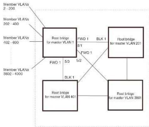
flowchart
graph TD
    A["Member VLANs 2 - 200"] --> B["Root bridge for master VLAN 1"]
    C["Member VLANs 202 - 400"] --> B
    D["Member VLANs 402 - 600"] --> B
    E["Member VLANs 3802 - 4000"] --> B
    B -->|FWD 1 5/3| F["Root bridge for master VLAN 401"]
    B -->|FWD 1 5/2| G["Root bridge for master VLAN 3801"]
    B -->|BLK 1| G
    B -->|BLK 1| H["Root bridge for master VLAN 201"]
    B -->|FWD 1 5/1| I["Root bridge for master VLAN 1"]
    B -->|FWD 1| J["Root bridge for master VLAN 201"]
In this example, each of the devices in the core is configured with a common set of master VLANs, each of which contains one or more member VLANs. Each of the member VLANs in an STP group runs the same instance of STP and uses the STP parameters configured for the master VLAN.
The STP group ID identifies the STP instance. All VLANs within an STP group run the same instance of STP. The master VLAN specifies the bridge STP parameters for the STP group, including the bridge priority. In this example, each of the devices in the core is configured to be the default root bridge for a different master VLAN. This configuration ensures that each link can be used for
PowerConnect(config-vlan-201) tag ethernet 1/2 ethernet 5/1 to 5/3
PowerConnect(config-vlan-201)#vlan 401
PowerConnect(config-vlan-401) ± spanning-tree priority 3
PowerConnect(config-vlan-401) tag ethernet 1/3 ethernet 5/1 to 5/3
...
PowerConnect(config-vlan-3601)#vlan 3801
PowerConnect(config-vlan-3801)#spanning-tree priority 20
PowerConnect(config-vlan-3801)#lag ethernet 1/20 ethernet 5/1 Lo 5/3
PowerConnect(config-vlan-3801) fexit
The next group of commands configures VLAN groups for the member VLANs. Notice that the VLAN groups do not contain the VLAN numbers assigned to the master VLANs. Also notice that no STP parameters are configured for the groups of member VLANs. Each group of member VLANs will inherit its STP settings from its master VLAN.
Set the bridge priority for each master VLAN to the highest priority (1) on one of the devices in the STP per VLAN group configuration. By setting the bridge priority to the highest priority, you make the device the default root bridge for the spanning tree. To ensure STP load balancing, make each of the devices the default root bridge for a different master VLAN.
PowerConnect(config)#vlan-group 1 vlan 2 to 200
PowerConnect(config-vlan-group-1)#tag ethernet 1/1 ethernet 5/1 to 5/3
PowerConnect(config-vlan-group-1)↓vlan-group 2 vlan 202 to 400
PowerConnect(config-vlan-group-2)†tag ethernet 1/2 ethernet 5/1 to 5/3
PowerConnect(config vlan-group 2) #vlan-group 3 vlan 402 to 600
PowerConnect(config-vlan-group-2) tag ethernet 1/3 ethernet 5/1 to 5/3
...
PowerConnect(config-vlan-group-19)#vlan-group 20 vlan 3082 to 4000
PowerConnect(config-vlan-group-20)#tag ethernet 1/20 ethernet 5/1 to 5/3
PowerConnect(config-vlan-group-20)#exit
The following group of commands configures the STP groups. Each STP group in this configuration contains one master VLAN, which contains a VLAN group. This example shows that an STP group also can contain additional VLANs (VLANs not configured in a VLAN group).
PowerConnect(config)#stp-group 1
PowerConnect(config-stp-group-1)4master-vlan 1
PowerConnect(config-stp-group-1) member-group 1
PowerConnect(config stp group 1)#member vlan 4001 4004 to 4010
PowerConnect (nonFIN-sln-group-1)4s+sn-group 2
NOTE
Dell PowerConnect ports automatically detect PVST+ BPDUs and enable support for the BPDUs once detected. You do not need to perform any configuration steps to enable PVST+ support. However, to support the IEEE 802.1Q BPDUs, you might need to enable dual-mode support.
Support for Cisco's Per VLAN Spanning Tree plus (PVST+), allows a Dell PowerConnect device to run multiple spanning trees (MSTP) while also interoperating with IEEE 802.1Q devices. Dell PowerConnect ports automatically detect PVST+ BPDUs and enable support for the BPDUs once detected. The enhancement allows a port that is in PVST+ compatibility mode due to auto-detection to revert to the default MSTP mode when one of the following events occurs:
• The link is disconnected or broken
• The link is administratively disabled
• The link is disabled by interaction with the link-keepalive protocol
This enhancement allows a port that was originally interoperating with PVST+ to revert to MSTP when connected to a Dell PowerConnect device.
Overview of PVST and PVST+
Per VLAN Spanning Tree (PVST) is a Cisco proprietary protocol that allows a Cisco device to have multiple spanning trees. The Cisco device can interoperate with spanning trees on other PVST devices but cannot interoperate with IEEE 802.1Q devices. An IEEE 802.1Q device has all its ports running a single spanning tree. PVST+ is an extension of PVST that allows a Cisco device to also interoperate with devices that are running a single spanning tree (IEEE 802.1Q).
Enhanced PVST+ support allows a Dell PowerConnect device to interoperate with PVST spanning trees and the IEEE 802.1Q spanning tree at the same time.
IEEE 802.1Q and PVST regions cannot interoperate directly but can interoperate indirectly through PVST+ regions. PVST BPDUs are tunnelled through 802.1Q regions, while PVST BPDUs for VLAN 1 (the IEEE 802.1Q VLAN) are processed by PVST+ regions. Figure 53 shows the interaction of IEEE 802.1Q, PVST, and PVST+ regions.
FIGURE 53 Interaction of IEEE 802.1Q, PVST, and PVST+ regions
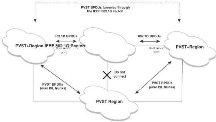
flowchart
graph TD
    A["PVST+Region IEEE 802.1Q Region"] -->|dual mode port| B["PVST Region"]
    B -->|PVST BPDUs (over ISL trunks)| A
    A -->|dual mode port| C["PVST+Region"]
    C -->|dual mode port| A
    C -->|PVST BPDUs (over ISL trunks)| B
    B -->|Do not connect| C
    style A fill:#f9f,stroke:#333
    style C fill:#f9f,stroke:#333
    note right of A: "PVST BPDUs tunneled through the IEEE 802.1Q region"
    note right of C: "PVST BPDUs (over ISL trunks)"
VLAN tags and dual mode
The dual-mode feature enables a port to send and receive both tagged and untagged frames.
When the dual-mode feature is enabled on a port, the port is an untagged member of one of its VLANs and is at the same time a tagged member of all its other VLANs. The untagged frames are supported on the port Port Native VLAN.
The dual-mode feature must be enabled on a Dell PowerConnect port in order to interoperate with
Configuring PVST+ support
PVST+ support is automatically enabled when the port receives a PVST BPDU. You can manually enable the support at any time or disable the support if desired.
If you want a tagged port to also support IEEE 802.1Q BPDUs, you need to enable the dual-mode feature on the port. The dual-mode feature is disabled by default and must be enabled manually.
A port that is in PVST+ compatibility mode due to auto-detection reverts to the default MSTP mode when one of the following events occurs:
• The link is disconnected or broken
• The link is administratively disabled
• The link is disabled by interaction with the link-keepalive protocol
This allows a port that was originally interoperating with PVST+ to revert to MSTP when connected to a Dell PowerConnect device.
Enabling PVST+ support manually
To immediately enable PVST+ support on a port, enter commands such as the following.
PowerConnect(config)#interface ethernet 1/1
PowerConnect(config-if-1/1)#pvst-mode
Syntax: [no] pvst-mode
NOTE
If you disable PVST+ support, the software still automatically enables PVST+ support if the port receives a BPDU with PVST+ format.
NOTE
If 802.1W and pvst-mode (either by auto-detection or by explicit configuration) are enabled on a tagged VLAN port, 802.1W will treat the PVST BPDUs as legacy 802.1D BPDUs.
Enabling dual-mode support
PowerConnect#show span pvst-mode
PVST+ Enabled on:
Port Method
1/1 Set by configuration
1/2 Set by configuration
2/10 Set by auto-detect
3/12 Set by configuration
4/24 Set by auto-detect
Syntax: show span pvst-mode
This command displays the following information.
TABLE 55 CLI display of PVST+ information
This field... Displays...
| Port The Dell PowerConnect port number. |
| NOTE: The command lists information only for the ports on which PVST+ support is enabled. |
| Method The method by which PVST+ support was enabled on the port. The method can be one of the following:Set by configuration - You enabled the support.Set by auto detect - The support was enabled automatically when the port received a PVST+ BPDU. |
Configuration examples
The following examples show configuration examples for two common configurations:
- Untagged IEEE 802.1Q BPDUs on VLAN 1 and tagged PVST+ BPDUs on other VLANs
- Tagged IEEE 802.1Q BPDUs on VLAN 1 and untagged BPDUs on another VLAN
Tagged port using default VLAN 1 as its port native VLAN
Figure 54 shows an example of a PVST+ configuration that uses VLAN 1 as the untagged default
Commands on the Dell PowerConnect Device
PowerConnect(config)#vlan-group 1 vlan 2 to 4
PowerConnect(config-vlan-group-1)#tagged ethernet 1/1
PowerConnect(config-vlan-group-1) ← exit
PowerConnect(config)#interface ethernet 1/1
PowerConnect(config-if-1/1) # dual-mode
PowerConnect(config-if-1/1)#pvst-mode
These commands configure a VLAN group containing VLANs 2, 3, and 4, add port 1/1 as a tagged port to the VLANs, and enable the dual-mode feature and PVST+ support on the port. The dual-mode feature allows the port to send and receive untagged frames for the default VLAN (VLAN 1 in this case) in addition to tagged frames for VLANs 2, 3, and 4. Enabling the PVST+ support ensures that the port is ready to send and receive PVST+ BPDUs. If you do not manually enable PVST+ support, the support is not enabled until the port receives a PVST+ BPDU.
The configuration leaves the default VLAN and the port Port Native VLAN unchanged. The default VLAN is 1 and the port Port Native VLAN also is 1. The dual-mode feature supports untagged frames on the default VLAN only. Thus, port 1/1 can send and receive untagged BPDUs for VLAN 1 and can send and receive tagged BPDUs for the other VLANs.
Port 1/1 will process BPDUs as follows:
- Process IEEE 802.1Q BPDUs for VLAN 1.
- Process tagged PVST BPDUs for VLANs 2, 3, and 4.
- Drop untagged PVST BPDUs for VLAN 1.
Untagged port using VLAN 2 as port native VLAN
Figure 55 shows an example in which a port Port Native VLAN is not VLAN 1. In this case, VLAN 1 uses tagged frames and VLAN 2 uses untagged frames.
FIGURE 55 Port Native VLAN 2 for Untagged BPDUs

These commands change the default VLAN ID, configure port 1/1 as a tagged member of VLANs 1 and 2, and enable the dual-mode feature and PVST+ support on port 1/1. Since VLAN 1 is tagged in this configuration, the default VLAN ID must be changed from VLAN 1 to another VLAN ID. Changing the default VLAN ID from 1 allows the port to process tagged frames for VLAN 1. VLAN 2 is specified with the dual-mode command, which makes VLAN 2 the port Port Native VLAN. As a result, the port processes untagged frames and untagged PVST BPDUs on VLAN 2.
NOTE
Although VLAN 2 becomes the port untagged VLAN, the CLI still requires that you add the port to the VLAN as a tagged port, since the port is a member of more than one VLAN.
Port 1/1 will process BPDUs as follows:
- Process IEEE 802.1Q BPDUs for VLAN 1.
- Process untagged PVST BPDUs for VLAN 2.
- Drop tagged PVST BPDUs for VLAN 1.
Note that when VLAN 1 is not the default VLAN, the ports must have the dual-mode feature enabled in order to process IEEE 802.1Q BPDUs.
For example, the following configuration is incorrect.
PowerConnect(config)#default-vlan-id 1000
PowerConnect(config)#vlan 1
PowerConnect(config-vlan-1)#tagged ethernet 1/1 to 1/2
PowerConnect(config-vlan-1)#exit
PowerConnect{config}#interface ethernet 1/1
PowerConnect(config-if-1/1)#pvst-mode
PowerConnect(config-if-1/1)#exit
PowerConnect(config)#interface ethernet 1/2
PowerConnect (config-if-1/2) #pvst-mode
PowerConnect {config-1f-1/2} #exit
In the configuration above, all PVST BPDUs associated with VLAN 1 would be discarded. Since IEEE BPDUs associated with VLAN 1 are untagged, they are discarded because the ports in VLAN 1 are tagged. Effectively, the BPDUs are never processed by the Spanning Tree Protocol. STP assumes that there is no better bridge on the network and sets the ports to FORWARDING. This could cause a layer 2 Inon.
PVRST compatibility
PVRST, the "rapid" version of per-VLAN spanning tree (PVST), is a Cisco proprietary protocol. PVRST corresponds to the Dell PowerConnect full implementation of IEEE 802.1w (RSTP). Likewise, PVST, also a Cisco proprietary protocol, corresponds to the Dell PowerConnect implementation of IEEE 802.1D (STP). When a Dell PowerConnect device receives PVRST BPDUs on a port configured to run 802.1w, it recognizes and processes these BPDUs and continues to operate in 802.1w mode. PVRST compatibility is automatically enabled when a port receives a PVRST BPDU.
BPDU guard
In an STP environment, switches, end stations, and other Layer 2 devices use Bridge Protocol Data Units (BPDUs) to exchange information that STP will use to determine the best path for data flow.
The BPDU guard, an enhancement to STP, removes a node that reflects BPDUs back in the network. It enforces the STP domain borders and keeps the active topology predictable by not allowing any network devices behind a BPDU guard-enabled port to participate in STP.
In some instances, it is unnecessary for a connected device, such as an end station, to initiate or participate in an STP topology change. In this case, you can enable the STP BPDU guard feature on the Dell PowerConnect port to which the end station is connected. STP BPDU guard shuts down the port and puts it into an errdisable state. This disables the connected device's ability to initiate or participate in an STP topology. A log message is then generated for a BPDU guard violation, and a CLI message is displayed to warn the network administrator of a severe invalid configuration. The BPDU guard feature provides a secure response to invalid configurations because the administrator must manually put the interface back in service if errdisable recovery is not enabled.
NOTE
BPDU guard is not supported on tagged ports. It can be configured on a tagged port, but the configuration will have no effect.
Enabling BPDU protection by port
Re-enabling ports disabled by BPDU guard
When a BPSU Guard-enabled port is disabled by BPDU Guard, the Dell PowerConnect device will place the port in errdisable state and display a message on the console indicating that the port is errdisabled (refer to "Example console messages" on page 284). In addition, the show interface command output will indicate that the port is errdisabled.
Example
PowerConnect+show int. e 2
Gigabit Ethernet2 is ERR-DISABLED (bpduguard), line protocol is down
To re-enable a port that is in errdisable state, you must first disable the port then re-enable it. Enter commands such as the following.
PowerConnect(config)#int e 2
PowerConnect {config-if-e1000-2} #disable
PowerConnect (config-if-e1000-2) flexible
If you attempt to enable an errdisabled port without first disabling it, the following error message will appear on the console.
PowerConnect(config-if-e1000-2)#enable
Port 2 is errdisabled, do disable first and then enable to enable it
Displaying the BPDU guard status
To display the BPDU guard state, enter the show running configuration or the show stp-bpdu-guard command.
For PowerConnect B-Series FCXdevices, enter the following commands.
PowerConnectshow stp-bpdu-guard
BPDU Guard Enabled on:
Ports: (Slk0/S1) 2 3 4 5 9 10 11 12 13 14 15 16
Ports: (Stk0/Sl) 17 18 19 20 21 22 23 24
Syntax: show stp-bpdu-guard
Example configurations
STP configured to ON, priority is level0, flow control enabled
mirror disabled, monitor disabled
Not member of any active trunks
Not member of any configured trunks
No port name
IPG MII 96 bits-time, IPG SMII 96 bits-time
IP MTU 1500 bytes
300 second input rate: 8 bits/sec, 0 packets/sec, 0.00% utilization
300 second output rate: 256 bits/sec, 0 packets/sec, 0.00% utilization
88 packets input, 15256 bytes, 0 no buffer
Received 75 broadcasts, 13 multicasts, 0 unicasts
1 input errors, 0 CRC, 0 frame, 0 ignored
0 runs, 0 giants
4798 packets output, 313268 bytos, 0 underruns
Transmitted 90 broadcasts, 4709
Example console messages
A console message such as the following is generated after a BPDU guard violation occurs on a system that is running MSTP.
PowerConnect(config-if-e1000-23)†MSTP: Received BPDU on BPDU guard enabled Port 23, errdisable Port. 23
A console message such as the following is generated after a BPDU guard violation occurs on a system that is running STP.
PowerConnect(config)#STP: Received BPDU on BPDU guard enabled Port 23 (vlan=1), orrdisable Port 23
A console message such as the following is generated after a BPDU guard violation occurs on a system that is running RSTP.
PowerConnect(config-vlan-1)#RSTP: Received BPDU on BPDU guard enabled Port 23 (vlan-1), errdisable Port 23
Root guard
Configure root guard on all ports where the root bridge should not appear. This establishes a protective network perimeter around the core bridged network, cutting it off from the user network.
NOTE
Root guard may prevent network connectivity if it is improperly configured. Root guard must be configured on the perimeter of the network rather than the core.
NOTE
Root guard is not supported when MSTP is enabled.
Enabling STP root guard
An STP root guard is configured on an interface by entering commands similar to the following.
PowerConnect (config) #interface ethernet 5/5
PowerConnect(config-if-e10000-5/5) spanning-tree root-protect
Syntax: [no] spanning-tree root-protect
Enter the no form of the command to disable STP root guard on the port.
Displaying the STP root guard
To display the STP root guard state, enter the show running configuration or the show spanning-tree root-protect command.
PowerConnect#show spanning-tree root-protect
Root Protection Enabled on:
Port
Syntax: show spanning-tree root-protect
Displaying the root guard by VLAN
You can display root guard information for all VLANs or for a specific VLAN. For example, to display
Error disable recovery
In case a BPDU guard violation occurs, a port is placed into an errdisable state which is functionally equivalent to a Disable state. Once in an errdiable state, it remains in that state until one of the following methods is used to return the port to an Enabled state.
- Manually disabling and enabling that interface
- Automatically, through the errdisable recovery mechanism
The errdisable recovery interval command is used to configure a time-out for ports in errdisable state, after which the ports are re-enabled automatically.
When BPDU guard puts a port into errdisabled state, the port remains in errdisabled state unless it is enabled manually by issuing a disable command and then the enable command on the associated interface or you have errisable recovery turned on. The errdisable command allows you to choose the type of error that automatically reenables the port after a specified amount of time.
Enabling error disable recovery
To enable errdisable recovery for BPDU Guard, enter a command such as the following.
PowerConnect(config)#errdisable recovery cause bpduguard
To enable error disable recovery for any reason, enter a command such as the following.
PowerConnect(config)#errdisable recovery cause all
Syntax: errdisable recovery [cause bpduguard | all]
The cause is the reason why the port is in the errdisable state. Valid values are bpduguard and all.
Use the bpduguard parameter to allow the port to recover from the errdisabled state, if the state was caused by a BPDU guard violation.
The all parameter allows ports to recover from an errdisabled state caused by any reason, for example, a BPDU Guard violation or loop detection violation.
Displaying the error disable recovery state by interface
The port status of errdisabled displays in the output of the show interface and the show interface brief commands. In this example, errdisabled is enabled on interface ethernet 1 and errdisabled is enabled because of a BPDU guard violation.
PowerConnectfshow interfaces ethernet 1
GigabitEthernet1 is ERR-DISABLED (bpduguard), line protocol is down
BPDU guard is Enabled, ROOT protect is Disabled
Hardware is GigabitEthernet, address is 000c.dba0.7100 (bia 000c.dba0.7100)
Configured speed auto, actual unknown, configured duplex fdx, actual unknown
Configured mdi mode AUTO, actual unknown
Member of L2 VLAN ID 2, port is untaqqed, port state is DISABLED
STP configured to ON, priority is level0, flow control enabled
mirror disabled, monitor disabled
Not member of any active trunks
Not member of any configured trunks
No port name
IPG MII 96 bits-time, IPG GMII 96 bits-time
IP MTU 1500 bytes
300 second input rate: 0 bits/sec, 0 packets/sec, 0.00% utilization
300 second output rate: 0 bits/sec, 0 packets/sec, 0.00% utilization
145 packets input, 23561 bytes, 0 no buffer
Received 124 broadcasts, 21 multicasts, 0 unicasts
1 input errors, 0 CRC, 0 frame, 0 ignored
0 runts, 0 giants
5067 packets output, 330420 bytes, 0 underruns
Transmitted 90 broadcasts, 4977 multicasts, 0 unicasts
0 output errors, 0 collisions
Displaying the recovery state for all conditions
Use the show errdisable recovery command to display all the default error disable recovery state for all possible conditions. In this example, port 6 is undergoing a recovery.
PowerConnect#show errdisable recovery
ErrDisable Reason Timer Status
Syntax: show errdisable summary
Errdisable Syslog messages
When the system places a port into an errdisabled state for BPDU guard, a log message is generated. When the errdisable recovery timer expires, a log message is also generated.
A Syslog message such as the following is generated after a port is placed into an errdisable state for BPDU guard.
STP: VLAN 90 BPDU-guard port 3 detect (Received BPDU), putting into err-disable state
A Syslog message such as the following is generated after the recovery timer expires.
ERR_DISABLE: Interface ethernet 3, err-disable recovery timeout
802.1s Multiple Spanning Tree Protocol
Multiple Spanning Tree Protocol (MSTP), as defined in IEEE 802.1s, allows multiple VLANs to be managed by a single STP instance and supports per-VLAN STP. As a result, several VLANs can be mapped to a reduced number of spanning-tree instances. This ensures loop-free topology for one or more VLANs that have the similar layer-2 topology. The Dell implementation supports up to 16 spanning tree instances in an MSTP enabled bridge which means that it can support up to 16 different Layer 2 topologies. The spanning tree algorithm used by MSTP is RSTP which provides quick convergence.
Multiple spanning-tree regions
Using MSTP, the entire network runs a common instance of RSTP. Within that common instance, one or more VLANs can be individually configured into distinct regions. The entire network runs the common spanning tree instance (CST) and the regions run a local instance. The local instance is known as Internal Spanning Tree (IST). The CST treats each instance of IST as a single bridge. Consequently, ports are blocked to prevent loops that might occur within an IST and also
FIGURE 56 MSTP configured network

flowchart
graph TD
    A["Switch 1"] -->|Port2/1| B["Switch 2"]
    A -->|Port1/2| C["Switch 3"]
    B -->|Port1/3| D["Switch 4"]
    B -->|Port1/1| E["Switch 5"]
    C -->|Port2/1| F["Switch 6"]
    D -->|Port2/3| G["Switch 4"]
    E -->|Port2/2| H["Switch 5"]
    F -->|Port1/4| I["Switch 3"]
    G -->|Port1/2| J["Switch 6"]
    H -->|Port1/2| K["Switch 5"]
    L["Switch 2"] -->|Port1/4| M["Switch 3"]
    M -->|Port3/1| N["Switch 5"]
    N -->|Port3/2| O["Switch 4"]
    O -->|Port3/3| P["Switch 5"]
The following definitions describe the STP instances that define an MSTP configuration.
Common Spanning (CST) - CST is defined in 802.1q and assumes one spanning-tree instance for the entire bridged network regardless of the number of VLANs. In MSTP, an MSTP region appears as a virtual bridge that runs CST.
Internal Spanning Tree (IST) - IST is a new terminology introduced in 802.1s. An MSTP bridge must handle at least these two instances: one IST and one or more MSTIs (Multiple Spanning Tree Instances). Within each MST region, the MSTP maintains multiple spanning-tree instances. Instance 0 is a special instance known as IST, which extends CST inside the MST region. IST always exists if the switch runs MSTP. Besides IST, this implementation supports up
Configuration notes
When configuring MSTP, note the following:
- With MSTP running, enabling static trunk on ports that are members of many VLANs (4000 or more VLANs) will keep the system busy for 20 to 25 seconds.
Configuring MSTP mode and scope
With the introduction of MSTP, a system can be either under MSTP mode or not under MSTP mode. The default state is to not be under MSTP mode. MSTP configuration can only be performed in a system under MSTP mode.
With a system configured under MSTP mode, there is a concept called MSTP scope. MSTP scope defines the VLANs that are under direct MSTP control. You cannot run 802.1D or 802.1w on any VLAN (even outside of MSTP scope) and you cannot create topology groups when a system is under MSTP mode. While a VLAN group will still be supported when a system is under MSTP mode, the member VLAN should either be all in the MSTP scope or all out of the MSTP scope.
When a system is configured from non-MSTP mode to MSTP mode, the following changes are made to the system configuration:
- All 802.1D and 802.1w STP instances are deleted regardless of whether the VLAN is inside the MSTP scope or not
• All topology groups are deleted
• Any GVRP configuration is deleted - Any VSRP configuration is deleted
- Single-span (if configured) is deleted
- MRP running on a VLAN inside MSTP scope is deleted
• The CIST is created and all VLANS inside the MSTP scope are attached with the CIST
Make sure that no physical layer-2 loops exist prior to switching from non-MSTP mode to MSTP mode. If, for example, you have an L2 loop topology configured as a redundancy mechanism before you perform the switch, a Layer 2 storm should be expected.
NOTE
Once under MSTP mode, CIST always controls all ports in the system. If you do not want a port to run MSTP, configure the no spanning-tree command under the specified interface configuration.
Using the [no] option on a system that is configured for MSTP mode changes the system to non-MSTP mode. When this switch is made, all MSTP instances are deleted together with all MSTP configurations. ALL VLANs inside the original MSTP scope will not run any Layer-2 protocols after the switch.
Reduced occurrences of MSTP reconvergence
When a VLAN is deleted, the Dell PowerConnect device retains the associated VLAN to MSTI mapping instead of deleting it from the configuration. This way, a VLAN can be pre-mapped to an MSTI and MSTP reconvergence may not be necessary when a VLAN is added to or deleted from the configuration. As long as the VLAN being created or deleted is pre-mapped to an MSTI, and the VLAN to MSTI mapping has not changed, MSTP reconvergence will not occur.
NOTE
MSTP reconvergence occurs when the VLAN to MSTI mapping is changed using the mstp instance command.
You can optionally remove VLAN to MSTI mappings from the configuration. Refer to "Deleting a VLAN to MSTI mapping" on page 292.
The following shows an example application.
Example application
The following example shows the running configuration file before and after deleting a VLAN from the configuration. The VLAN to MSTI mapping is retained in the running configuration, even after the VLAN is deleted.
PowerConnect(config-vlan-20)†show run
Current configuration:
!
ver 7.2.00sT7f1
!
!
vlan 1 name DEFAULT-VLAN by port
no spanning-tree
!
vlan 10 by port
tagged else 1 to 2
no spanning tree
!
vlan 20 by port <---- VLAN 20 configuration
tagged else 1 to 2
no spanning-tree
!
mstp scope all
mstp instance 0 vlan 1
mstp instance 1 vlan 20
mstp start
some lines omitted for brevity...
PowerConnect(config-vlan-20)‡no vlan 20 <---- VLAN 20 deleted
PowerConnect(config-vlan-20)†show run
Current configuration:
!
ver 7.2.00aT7f1
!
!
vlan 1 name DEFAULT-VLAN by port
no spanning-tree
!
vlan 10 by port
tagged else 1 to 2
no spanning-tree
!
mstp scope all
The instance parameter defines the number for the instance of MSTP that you are deleting.
The vlan parameter identifies one or more VLANs or a range of VLANs to the instance defined in this command.
The vlan-group parameter identifies one or more VLAN groups to the instance defined in this command.
Viewing the MSTP configuration digest
The MSTP Configuration Digest indicates the occurrence of an MSTP reconvergence. The Configuration Digest is recalculated whenever an MSTP reconvergence occurs. To view the Configuration Digest, use the show mstp config command. The following shows an example output.
PowerConnect(config-vlan-20)↑ show mstp config
MSTP CONFIGURATION
Scope : all system
Revision : 0
Version : 3 (MSTP mode)
Config Digest: 0x9bbda9c70d91f633ele145fbcbf8d321
Status : Started
Instance VLANs
0 1 1 10 20
Syntax: show mstp config
Configuring additional MSTP parameters
To configure a switch for MSTP, you could configure the name and the revision on each switch that is being configured for MSTP. You must then create an MSTP Instance and assign an ID. VLANs are
• "Forcing ports to transmit an MSTP BPDU"
- "Activating MSTP on a switch"
Setting the MSTP name
Each switch that is running MSTP is configured with a name. It applies to the switch which can have many different VLANs that can belong to many different MSTP regions.
To configure an MSTP name, use a command such as the following at the Global Configuration level.
PowerConnect(config)#nstp name Dell
Syntax: [no] mstp name
The name parameter defines an ASCII name for the MSTP configuration. The default name is for the name variable to be blank.
Setting the MSTP revision number
Each switch that is running MSTP is configured with a revision number. It applies to the switch which can have many different VLANs that can belong to many different MSTP regions.
To configure an MSTP revision number, use a command such as the following at the Global Configuration level.
PowerConnect(config)#instp revision 4
Syntax: [no] mstp revision
The revision parameter specifies the revision level for MSTP that you are configuring on the switch. It can be a number from 0 and 65535. The default revision number is 0.
Configuring an MSTP instance
An MSTP instance is configured with an MSTP ID for each region. Each region can contain one or more VLANs. The Dell implementation of MSTP allows you to assign VLANs or ranges of VLANs to an MSTP instance before or after they have been defined. If pre-defined, a VLAN will be placed in
The no option moves a VLAN or VLAN group from its assigned MSTI back into the CIST.
NOTE
The system does not allow an MSTI without any VLANs mapped to it. Consequently, removing all VLANs from an MSTI, deletes the MSTI from the system. The CIST by contrast will exist regardless of whether or not any VLANs are assigned to it or not. Consequently, if all VLANs are moved out of a CIST, the CIST will still exist and functional.
Configuring bridge priority for an MSTP instance
Priority can be configured for a specified instance. To configure priority for an MSTP instance, use a command such as the following at the Global Configuration level.
PowerConnect(config)#matp instance 1 priority 8192
Syntax: [no] mstp instance
The
You can set a priority to the instance that gives it forwarding preference over lower priority instances within a VLAN or on the switch. A higher number for the priority variable means a lower forwarding priority. Acceptable values are 0 - 61440 in increments of 4096. The default value is 32768.
Setting the MSTP global parameters
MSTP has many of the options available in RSTP as well as some unique options. To configure MSTP Global parameters for all instances on a switch.
PowerConnect(config)#matp force-version 0 forward-delay 10 hello-time 4 max-age 12 max-hops 9
Syntax: [no] mstp force-version
The force-version parameter forces the bridge to send BPDUs in a specific format. You can specify one of the following
The max-hops
Setting ports to be operational edge ports
You can define specific ports as edge ports for the region in which they are configured to connect to devices (such as a host) that are not running STP, RSTP, or MSTP. If a port is connected to an end device such as a PC, the port can be configured as an edge port. To configure ports as operational edge ports enter a command such as the following.
PowerConnect{config}#matp admin-edge-port ethernet 3/1
Syntax: [no] mstp admin-edge-port ethernet
Specify the
• PowerConnect B-Series FCX stackable switches -
Setting automatic operational edge ports
You can configure a Layer 3 switch to automatically set a port as an operational edge port if the port does not receive any BPDUs since link-up. If the port receives a BPDU later, it is automatically reset to become an operational non-edge port. This feature is set globally to apply to all ports on a router where it is configured. This feature is configured as shown in the following.
PowerConnect(config)#matp edge-port-auto-detect
Syntax: [no] mstp edge-port-auto-detect
NOTE
If this feature is enabled, it takes the port about 3 seconds longer to come to the enable state.
Setting point-to-point link
You can set a point-to-point link between ports to increase the speed of convergence. To create a point-to-point link between ports, use a command such as the following at the Global Configuration Level
- PowerConnect B-Series FCX stackable switches -
Forcing ports to transmit an MSTP BPDU
To force a port to transmit an MSTP BPDU, use a command such as the following at the Global Configuration level.
PowerConnect(config)#mslp force-migration-check ethernet. 3/1
Syntax: [no] mstp force-migration-check ethernet
The
- PowerConnect B-Series FCX stackable switches -
MSTP scope must be enabled on the switch as described in "Configuring MSTP mode and scope" on page 290 before MSTP can be enabled.
To enable MSTP on your switch, use the following at the Global Configuration level. PowerConnect(config)#matp start
Syntax: [no] mstp start
The [no] option disables MSTP from operating on a switch.
Example
In Figure 57 four Brocade device routers are configured in two regions. There are four VLANs in four instances in Region 2. Region 1 is in the CIST.
FIGURE 57 Sample MSTP configuration

flowchart
graph TD
    RTR1["Port10/1"] -->|Port10/2| Core1["Port 2/16"]
    Core1 -->|Ports 2/9-2/12| Core2["Port 3/17-3/20"]
    Core2 -->|Ports 3/5-3/6| LAN4["LAN4"]
    Core2 -->|Ports 3/5-3/6| LAN4
    Core1 -->|Ports 2/13-2/14| LAN4
    Core2 -->|Ports 3/1-3/2| LAN4
Reglon 2
RTR1 configuration
PowerConnect(config-vlan-4093)#tagged ethernet 10/1 to 10/2
PowerConnect(config-vlan-4093)#exit
PowerConnect(config)#mstp scope all
PowerConnect(config)#matp name Regl
PowerConnect(config)#matp Revision 1
PowerConnect(config)#mstp admin-pt2pt-mac ethernet 10/1 to 10/2
PowerConnect {config} #matp start
PowerConnect(config)#hostname RTR1
Core 1 configuration
PowerConnect(config)#trunk ethernet 2/9 to 2/12 ethernet 2/13 to 2/14
PowerConnect(config-vlan-1)#name DEFAULT-VLAN by port
PowerConnect(config-vlan-1)#exit
PowerConnect(config)#vlan 20 by port
PowerConnect(config-vlan-20) tagged ethernet 2/9 to 2/14 ethernet 2/16
Ratioscience (scrofa m. 2014)
Core2 configuration
PowerConnect(config)#trunk ethernet 3/5 to 3/6 ethernet 3/17 to 3/20
PowerConnect(config)#vlan 1 name DEFAULT-VLAN by port
PowerConnect(config-vlan-1)#exit
PowerConnect(config)#vlan 20 by port
PowerConnect (config-vlan-20) 4tagged ethernet 3/5 to 3/6 ethernet 3/17 to 3/20
PowerConnect(config-vlan-20) *exit
PowerConnect(config)#vlan 21 by port
PowerConnect(config-vlan-21) tagged ethernet 3/5 to 3/6 ethernet 3/17 to 3/20
PowerConnect(config-vlan-21)#exit
PowerConnect(config)#vlan 22 by port.
PowerConnect(config-vlan-22)†tagged ethernet 3/5 to 3/6 ethernet 3/17 to 3/20
PowerConnect(config-vlan-22)#exit
PowerConnect(config)#mstp scope all
PowerConnect{config}#matp name HR
PowerConnect(config)#mstp revision 2
PowerConnect(config)#matp instance 20 vlan 20
PowerConnect(config)#mstp instance 21 vlan 21
PowerConnect(config)#mstp instance 22 vlan 22
PowerConnect{config}#matp admin-pt2pt-mac ethernet 3/17 to 3/20 ethernet 3/5 to
3/6
PowerConnect {config} #matp admin-pt2pt-mac ethernet 3/10
PowerConnect(config)#mstp disable ethernet 3/7 ethernet 3/24
PowerConnect(config)#mstp start
PowerConnect(config)#hostname CORE2
LAN 4 configuration
PowerConnect(config)#trunk ethernet 3/5 to 3/6 ethernet 3/1 to 3/2
PowerConnect(config)#vlan 1 name DEFAULT-VLAN by port
PowerConnect(config-vlan-1)#exit
PowerConnect(config)#vlan 20 by port
PowerConnect(config-vlan-20)#tagged ethernet 3/1 to 3/2 ethernet 3/5 to 3/6
PowerConnect(config)#exit
PowerConnect(config)#vlan 21 by port
PowerConnect(config-vlan-21)#tagged ethernet 3/1 to 3/2 ethernet 3/5 to 3/6
PowerConnect(config-vlan-21) *exit
PowerConnect(config)#vlan 22 by port
PowerConnect(config-vlan-22) tagged ethernet 3/1 to 3/2 ethernet 3/5 to 3/6
Bosco/Companza (confl. al. 1204)
PowerConnect#show mst.p
MSTP Instance 0 (CIST) - VLANs: 1
| Bridge Identifier hex | Bridge MaxAge sec | Bridge Hello sec | Bridge FwdDly sec | Bridge Hop cnt | Root MaxAge sec | Root Hello sec | Root FwdDly sec | Root Hop cnt |
| 80000000dbz80af01 | 20 | 2 | 15 | 20 | 20 | 2 | 15 | 18 |
| Root | ExtPath | RegionalRoot | IntPath | Designated | Root |
| Bridge | Cost | Bridge | Cost | Bridge | Port |
| hex | hex | hex | |||
| 8000000480bb9876 | 2000 | 8000000cdb@0af01 | C | 8000000480bb9876 | 3/1 |
| Port Num | Fri Cost | PortPath | P2P Mac | Edge Port | Role | State | Designated cost | Designated bridge |
| 3/1 | 12B | 2000 | T | F | ROOT | FORWARDING | 0 | 8000000480bb9876 |
MGTP Instance 1 - VLANs: 2
| Bridge | Max | RegionalRoot | IntPath | Designated | Root | Root |
| Identifier | Hop | Bridge | Cost | Bridge | Port | Hop |
| box | cnt | box | box | cnt | ||
| 8001000cdb80sf01 | 20 | 8001000cdb80sf01 | 0 | 8001000cdb80sf01 | Root | 20 |
| Port Num | Pri Cost | PortPath | Role | State | Designated cost | Designated bridge |
| 3/1 | 128 | 2000 | MASTER | FORNARDING | 0 | 8001000cdb80af01 |
Syntax: show mstp
The
TABLE 56 Output from Show MSTP
This field... Displays...
MSTP Instance The ID of the MSTP instance whose statistics are being displayed. For
the CIST, this number is 0.
TABLE 56 Output from Show MSTP (Continued)
| This field... | Displays... |
| ExtPath Cost The configured path cost on a link connected to this port to an external MSTP region. | |
| Regional Root Bridge The Regional Root Bridge is the MAC address of the Root Bridge for the local region. | |
| IntPath Cost The configured path cost on a link connected to this port within the internal MSTP region. | |
| Designated Bridge The MAC address of the bridge that sent the best BPDU that was received on this port. | |
| Root Port Port indicating shortest path to root. Set to "Root" if this bridge is the root bridge. | |
| Port Num The port number of the interface. | |
| Pri The configured priority of the port. The default is 128. | |
| PortPath Cost Configured or auto detected path cost for port. | |
| P2P Mac indicates if the port is configured with a point-to-point link:• T - The port is configured in a point-to-point link• F - The port is not configured in a point-to-point link | |
| Edge indicates if the port is configured as an operational edge port:• T - Indicates that the port is defined as an edge port.• F - indicates that the port is not defined as an edge port | |
| Role The current role of the port:• Master• Root• Designated• Alternate• Backup• Disabled | |
State The port current spanning tree state. A port can have one of the
following states:
- Forwarding
PowerConnect#show mstp 1
MSTP Instance 1 - VLANs: 2
| Bridge | Max | RegionalRoot | IntPath | Designated | Root | Root | |
| Identifier | Hop | Bridge | Cost | Bridge | Port | Hop | |
| hex | cnl | hex | hex | cnl | |||
| 8001000cdb80af01 | 20 | 8001000cdb80af01 | 0 | 8001000cdb80af01 | Root | 20 | |
| Port | Pri | PortPath | Role | State | Designated cost | Designated bridge | |
| Num | Cost | ||||||
| 3/1 | 128 | 2000 | MASTER | TORWARDING | 0 | 8001000cdb80af01 | |
Refer to Table 56 for details about the display parameters.
Displaying MSTP information for CIST instance 0
Instance 0 is the Common and Internal Spanning Tree Instance (CIST). When you display information for this instance there are some differences with displaying other instances. The following example displays MSTP information for CIST Instance 0.
PowerConnect#show mstp 0
MSTP Instance 0 (CIST) - VLANs: 1
| Bridge | Bridge | Bridge | Bridge | Bridge | Root | Root | Root | Root | |
| Identifier | MaxAgo | Hello | FwdDly | Hop | MaxAgo | Hello | FwdDly | Hop | |
| hex | sec | sec | sec | cnt | sec | sec | sec | cnt | |
| 6000000cdb80af01 | 20 | 2 | 15 | 20 | 20 | 2 | 15 | 19 | |
| Root | ExtPath | RegionalRoot | IntPath | Designated | Root | ||||
| Bridge | Cost | Bridge | Cost | Bridge | Port | ||||
| box | hcx | hcx | |||||||
| 80000004B0bbb9876 | 2000 | 8000000cdb80af01 | 0 | 8000000480bbb9876 | |||||
| Port | Fri | PortPath | P2F | Edge | Role | State | Designated cost | Designated bridge | |
| Num | Cost | Mac | Port | ||||||
| 3/1 | 12B | 2000 | T | F | ROOT | FORWARDING | 0 | 8000000480bbb9876 | |
To display details about the MSTP configuration, enter the following command.
PowerConnect#show mstp detail MSTP Instance 0 (CIST) - VLANs: 4093
Bridge: 800000b000c0000 [Priority 32768, SysId 0, Mac 00b000c0000] FwdDelay 15, HelloTime 2, MaxHops 20, TxHoldCount 6 Port 6/54 - Role: DESIGNATED - State: FORWARDING PathCost 20000, Priority 12#, OperEdge T, OperPt2PtMac F, Boundary I Designated - Root 800000b000c0000, RegionalRoot 80000b000c0000, Bridge 800000b000c0000, ExtCost 0, IntCost 0 ActiveTimors - helloWhen 1 MachineState - PRX-DISCARD, PTX-IDLE, PPM-SENDING_RSTP, PIM-CURRENT PRI-ACTIVE_PORT, PST-FORWARDING, TCM-INACTIVE BPDUs - Rcvd MST 0, RST 0, Config 0, TCN 0 Sent MST 6, RST 0, Config 0, TCN 0
Refer to Table 56 for explanation about the parameters in the output.
Syntax: show mstp [
Enter an MSTP ID for
Configuring Basic Layer 2 Features
Chapter
9
Table 57 lists the individual Dell PowerConnect switches and the basic Layer 2 features they support.
TABLE 57 Supported basic Layer 2 features
| Feature PowerConnect B-Series FCX | |
| 16,000 MAC addresses per switch Yes | |
| 32,000 MAC addresses per switch Yes | |
| MAC learning rate control Yes | |
| Multi-port static MAC address Yes | |
| Static MAC entries with option to set traffic priority | Yes |
| Flow-based MAC address learning Yes | Enabled by default on PowerConnect B-Series FCX devices. There is no CLI command to enable or disable it. |
| Port-based VLANs Yes | |
| Address locking (for MAC addresses) Yes | |
| MAC address filter override of 802.1X | Yes |
| MAC address filtering (filtering on source and destination MAC addresses) | Yes |
| Ability to disable MAC learning | Yes |
| Dynamic buffer allocation for QoS priorities | Yes |
- For information about configuring IP addresses, DNS resolver, DHCP assist, and other IP-related parameters, refer to Chapter 26, "Configuring IP".
- For information about the Syslog buffer and messages, refer to Chapter 41, "Using Syslog".
About port regions
This section describes port regions on PowerConnect switches.
PowerConnect B-Series FCX device port regions
The port region rules for PowerConnect B-Series FCX devices are as follows:
- For all platforms, a 24-port Gbps module has one port region. In addition, any 10 Gbps ports on the device also belong to this single port region.
• For all platforms, the 48-port Gbps module has two port regions:
- Ports 1 - 24 belong to port region 0
- Ports 25 - 48 belong to port region 1
- For PowerConnect B-FCX648 devices with two 10 Gbps XFP ports, and a two 10 Gbps CX4 stacking ports:
- The two 10 Gbps XFP ports belong to port region 0 (along with ports 1-24)
- The two 10 Gbps CX4 stacking ports belong to port region 1 (along with ports 25 - 48)
- For PowerConnect B-FCX648 devices with four 10 Gbps SFP+ ports:
- 10 Gbps SFP+ ports 3 and 4 belong to port region 0 (along with ports 1 -24)
- 10 Gbps SFP+ ports 1 and 2 ports belong to port region 1 (along with ports 25 - 48)
Enabling or disabling the Spanning Tree Protocol (STP)
You can also enable and disable spanning tree on a port-based VLAN and on an individual port basis, and enable advanced STP features. Refer to Chapter 8, "Configuring Spanning Tree Protocol (STP) Related Features".
Modifying STP bridge and port parameters
You can modify the following STP Parameters:
- Bridge parameters – forward delay, maximum age, hello time, and priority
- Port parameters – priority and path cost
For configuration details, refer to "Changing STP bridge and port parameters" on page 210.
MAC learning rate control
You can set a rate limit to control CPU address updating. The range for this rate limit is 200 - 50,000 per second. The MAC learning rate limit applies to each packet processor, which means that for a system with two packet processors, each processor can send address messages to the CPU at the established rate limit.
Syntax: [no] cpu-limit addr-msgs
NOTE
Actual rates in hardware may have a variance of +200 or -100.
Changing the MAC age time and disabling MAC address learning
To change the MAC address age timer, enter a command such as the following.
PowerConnect(config)#mac-age-time 60
Syntax: [no] mac-age-time
Disabling the automatic learning of MAC addresses
By default, when a packet with an unknown Source MAC address is received on a port, the Dell
PowerConnect device learns this MAC address on the port.
You can prevent a physical port from learning MAC addresses by entering the following command.
PowerConnect(config)#interface ethernet 3/1
PowerConnect(config-if-e1000-3/1)↑mac-learn-disable
Syntax: [no] mac-learn disable
Use the no form of the command to allow a physical port to learn MAC addresses.
Configuration notes and feature limitations
- This command is not available on virtual routing interfaces. Also, if this command is configured on the primary port of a trunk, MAC address learning will be disabled on all the ports in the trunk.
- Entering the mac-learn-disable command on tagged ports disables MAC learning for that port in all VLANs to which that port is a member. For example, if tagged port 3/1 is a member of VLAN 10, 20, and 30 and you issue the mac-learn-disable command on port 3/1, port 3/1 will not learn MAC addresses, even if it is a member of VLAN 10, 20, and 30.
Displaying the MAC address table
To display the MAC table, enter the following command.
| PowerConnectfshow mac-address | |||
| Total active entries from all ports = 3 | |||
| Total static entries from all ports = 1 | |||
| MAC Address | Port | Type | VLAN |
| 1234.1234.1234 | 15 | Static | 1 |
| 0004.8038.2f24 | 14 | Dynamic | 1 |
| 0004.8038.2f00 | 13 | Dynamic | 1 |
| 0010.5a86.b159 | 10 | Dynamic | 1 |
NOTE
Dell PowerConnect devices running Layer 3 code also support the assignment of static IP Routes, static ARP, and static RARP entries. For details on configuring these types of static entries, refer to "Configuring static routes" on page 819 and "Creating static ARP entries" on page 814.
You can manually input the MAC address of a device to prevent it from being aged out of the system address table.
This option can be used to prevent traffic for a specific device, such as a server, from flooding the network with traffic when it is down. Additionally, the static MAC address entry is used to assign higher priorities to specific MAC addresses.
You can specify traffic priority (QoS) and VLAN membership (VLAN ID) for the MAC Address as well as specify the device type of either router or host.
The default and maximum configurable MAC table sizes can differ depending on the device. To determine the default and maximum MAC table sizes for your device, display the system parameter values. Refer to "Displaying and modifying system parameter default settings" on page 321.
Multi-port static MAC address
Many applications, such as Microsoft NLB, Juniper IPS, and Netscreen Firewall, use the same MAC address to announce load-balancing services. As a result, a switch must be able to learn the same MAC address on several ports. Multi-port static MAC allows you to statically configure a MAC address on multiple ports using a single command.
Configuration notes
• This feature is applicable for Layer 2 traffic.
- This feature can be used to configure unicast as well as IPv4 and IPv6 multicast MAC addresses on one or more ports. However, when a multicast MAC address is configured, the corresponding MAC address entry cannot be used for IGMP snooping. For IPv4 multicast addresses (range 0100.5e00.000 to 0100.5e7f.fff) and IPv6 multicast addresses (range 3333.0000.0000 to 3333.fff.fff), use IGMP/MLD snooping. Other multicast addresses can also be configured on the ports using this feature.
or
Syntax: [no] static-mac-address
The
The
The priority
NOTE
The location of the static-mac-address command in the CLI depends on whether you configure port-based VLANs on the device. If the device does not have more than one port-based VLAN (VLAN 1, which is the default VLAN that contains all the ports), the static-mac-address command is at the global CONFIG level of the CLI. If the device has more than one port-based VLAN, then the static-mac-address command is not available at the global CONFIG level. In this case, the command is available at the configuration level for each port-based VLAN.
Configuring VLAN-based static MAC entries
You can configure a VLAN to drop packets that have a particular source or destination MAC address.
You can configure a maximum of 2048 static MAC address drop entries on a Dell PowerConnect device.
Use the CLI command show running-config to view the static MAC address drop entries currently configured on the device.
Command syntax
To configure a VLAN to drop packets with a source or destination MAC address of 1145.5563.67FF, enter the following commands.
For example, to remove entries for the MAC address 000d.cd80.00d0 in all VLANs, enter the following command at the Privilege EXEC level of the CLI.
PowerConnect#clear mac-address 000d.cb80.00d0
Syntax: clear mac-address
If you enter clear mac-address without any parameter, the software removes all MAC address entries.
Use the
Use the ethernet
Use the vlan
Flow-based MAC address learning
NOTE
Flow-based MAC address learning is supported on PowerConnect B-Series FCX Series devices. However, on PowerConnect B-Series FCX Series, this feature is enabled by default. There is no command to enable or disable it.
Feature overview
With regular MAC address learning, when a new MAC address is learned, it is programmed in the same location (hardware index) in all packet processors in a PowerConnect Layer 2 or Layer 3 switch. There are multiple packet processors (one per port region) in a compact switch, and in each module in a chassis-based switch. With regular MAC address learning, MAC addresses are global, meaning the hardware MAC table is identical across all packet processors.
With the introduction of flow-based MAC address learning, when a new source MAC address is learned, it is programmed only in the source packet processor (the processor that received the packet). The destination MAC address gets added to other packet processors on demand,
How flow-based learning works
When a packet processor, let call it PP 1, receives an incoming packet with source MAC address X, it sends a new address message to the CPU. The system learns MAC address X by adding it to the software MAC table in the CPU, then programming it in the hardware MAC table in the source packet processor, in this case PP 1. If the MAC address is learned on a trunk port, the MAC address is also programmed on all of the packet processors that have ports in the same trunk group.
When another packet processor, let call it PP 2, receives an incoming packet and the packet destination MAC address matches source MAC address X, it floods the packet in hardware as an unknown unicast packet and copies the packet to the CPU. The system locates the MAC address in the software MAC table, then programs the MAC address in the hardware MAC table in PP 2. If the MAC address is learned on a trunk port, the MAC address is also programmed on all of the packet processors that have ports in the same trunk group. Once the MAC address is programmed in hardware, subsequent packets with this destination MAC are forwarded as known unicast packets and are not copied to the CPU.
Flow-based MAC addresses are aged out by the source packet processor according to the MAC age time learned on the local port. Furthermore, when a flow-based MAC address is aged out from the source packet processor, it is also aged out from all other packet processors on which the address is programmed. In the above example, when MAC address X is aged out from PP1, it is also aged out from PP2.
NOTE
Even when flow-based MAC address learning is enabled, some MAC addresses, including but not limited to control MACs, static MACs, multicast MACs, and MAC addresses resolved through ARP, will continue to be global MAC addresses. These MAC addresses are always programmed in all packet processors in a Layer 2 or Layer 3 switch.
NOTE
Global MAC addresses have priority over dynamic flow-based MAC addresses. To ensure that global MAC addresses are in sync across all packet processors, flow-based MAC addresses may be overwritten in one or more packet processors. The MAC addresses will be relearned and reprogrammed using the flow-based method as needed by incoming traffic flows.
- A source MAC address is learned only on the ingress (source) packet processor. The MAC address is added to other packet processors as needed by their incoming traffic flows. During a brief period until the destination MAC address is successfully added to the hardware MAC table, unknown unicast flooding is expected on the VLAN.
- When a flow-based MAC address moves, it is deleted from all of the packet processors, then relearned on each packet processor individually, as needed by incoming traffic flows.
- The software MAC address table in the CPU uses a hashing algorithm. Because hash collisions can occur and may consume software resources, the PowerConnect may not be able to support up to 32K MAC addresses.
- The system can scale up to 32K MAC addresses, however, each packet processor is limited to a maximum of 16K MAC addresses. This limit still applies, as this is a hardware limitation.
Configuring flow-based MAC address learning
To configure flow-based MAC address learning, simply enable it globally. If necessary, increase the capacity of the MAC address table as well.
Enabling flow-based MAC address learning
To enable flow-based MAC address learning, enter the following command at the Global CONFIG level of the CLI.
PowerConnect(config)#mac-learning-flow-based
This command enables flow-based MAC address learning. All dynamically-learned MAC addresses are flushed from the hardware and software MAC tables and are subsequently learned using flow-based MAC address learning.
Syntax: [no] mac-learning-flow-based
Use the no form of the command to disable flow-based MAC address learning. When disabled, all dynamically-learned MAC addresses are flushed from the hardware and software MAC tables and are subsequently learned using global MAC address learning.
-
-
-
-
-
-
-
-
-
-
-
-
-
-
-
-
-
-
-
-
-
-
-
-
-
-
-
-
-
-
-
-
-
-
-
-
-
-
-
-
-
-
-
-
-
-
-
-
-
-
-
-
-
-
-
-
-
-
-
-
-
-
-
-
-
-
-
-
-
-
-
-
-
-
-
-
-
-
-
-
-
-
-
-
-
-
-
-
- 90.
-
-
-
-
-
-
-
-
-
-
-
-
-
-
-
-
-
-
-
-
-
-
-
-
-
-
-
-
-
-
-
-
-
-
-
-
-
-
-
-
-
-
-
-
-
-
-
-
-
-
-
-
-
-
-
-
-
-
-
-
-
-
-
-
-
-
-
-
-
-
-
-
-
-
-
-
-
-
-
-
-
-
-
-
-
-
-
Syntax: system-max mac
The
Use the command show default values to display the default, maximum, and currently configured values for the MAC address table.
Displaying information about flow-based MACs
The show mac-address command includes information related to flow-based MAC address learning. The following shows an example show mac output.
PowerConnect† show mac
Total active entries from all ports = 15
MAC-Address Port Type Index
0000.0000.0001 1/1 Dynamic NA
0000.0000.0002 1/1 Dynamic NA
In the above example, since both MAC address entries are flow-based and are located on different packet processors (hardware index), the Index field displays NA (not applicable).
Syntax: show mac
To display all of the packet processors that have a particular flow-based MAC address, use the show mac-address vlan command.
PowerConnect#show mac-address vlan 1 0000.0000.0001
Total active entries from all ports = 16
MAC-Address Port Type Index
0000.0000.0001 1/1 Dynamic NA
Present in following devices (at hw index) :-
(8196) 4 (8196)
In the above example, the MAC address 0000.0000.0001 is programmed in packet processors 0 and 4, and the hardware index is 8196.
Syntax: vlan
Syntax: vlan
The
The
You can configure up to 4063 port-based VLANs on a device running Layer 2 code or 4061 port-based VLANs on a device running Layer 3 code. Each port-based VLAN can contain either tagged or untagged ports. A port cannot be a member of more than one port-based VLAN unless the port is tagged. On both device types, valid VLAN IDs are 1 - 4095. You can configure up to the maximum number of VLANs within that ID range.
NOTE
VLAN IDs 4087, 4090, and 4093 are reserved for Dell internal use only. VLAN 4094 is reserved for use by Single STP. Also, if you are running an earlier release, VLAN IDs 4091 and 4092 may be reserved for Dell internal use only. If you want to use VLANs 4091 and 4092 as configurable VLANs, you can assign them to different VLAN IDs. For more information, refer to "Assigning different VLAN IDs to reserved VLANs 4091 and 4092" on page 445.
NOTE
The second command is optional and also creates the VLAN if the VLAN does not already exist. You can enter the first command after you enter the second command if you first exit to the global CONFIG level of the CLI.
Assigning IEEE 802.1Q tagging to a port
When a port is tagged, it allows communication among the different VLANs to which it is assigned. A common use for this might be to place an email server that multiple groups may need access to on a tagged port, which in turn, is resident in all VLANs that need access to the server.
Defining MAC address filters
MAC layer filtering enables you to build access lists based on MAC layer headers in the Ethernet/IEEE 802.3 frame. You can filter on the source and destination MAC addresses. The filters apply to incoming traffic only.
You configure MAC address filters globally, then apply them to individual interfaces. To apply MAC address filters to an interface, you add the filters to that interface MAC address filter group.
The device takes the action associated with the first matching filter. If the packet does not match any of the filters in the access list, the default action is to drop the packet. If you want the system to permit traffic by default, you must specifically indicate this by making the last entry in the access list a permit filter. An example is given below.
Syntax: mac filter
For devices running Layer 3 code, the MAC address filter is applied to all inbound Ethernet packets, including routed traffic. This includes those port associated with a virtual routing interface. However, the filter is not applied to the virtual routing interface. It is applied to the physical port.
When you create a MAC address filter, it takes effect immediately. You do not need to reset the system. However, you do need to save the configuration to flash memory to retain the filters across system resets.
Configuration notes and limitations
- MAC address filtering on PowerConnect devices is performed in hardware.
- MAC address filtering on PowerConnect devices differ from other Dell PowerConnect devices in that you can only filter on source and destination MAC addresses. Other Dell PowerConnect devices allow you to also filter on the encapsulation type and frame type.
- MAC address filtering applies to all traffic, including management traffic. To exclude management traffic from being filtered, configure a MAC address filter that explicitly permits all traffic headed to the management MAC (destination) address. The MAC address for management traffic is always the MAC address of port 1.
• MAC address filters that have a global deny statement can cause the device to block all
PowerConnect(config)# mac filter 3 deny any 0180.c200.0000 ffff.ffff.fff0 PowerConnect(config)# mac filter 4 deny any 0000.1234.5678 ffff.ffff.fff0 PowerConnect(config)# mac filter 5 deny any 0000.2345.6789 ffff.ffff.fff0 PowerConnect(config)# mac filter 1024 permit any any PowerConnect(config)# int e 1 PowerConnect(config-if-e1000-1)# mac filter-group 1 to 5 1024
These commands configure filter 1 to deny traffic with a source MAC address that begins with "3565" to any destination, and configure filters 2 through 5 to deny traffic with the specified destination MAC addresses. Filter 1024 permits all traffic that is not denied by any other filter.
NOTE
Once you apply a MAC address filter to a port, the device drops all Ethernet traffic on the port that does not match a MAC permit filter on the port.
Syntax: [no] mac filter
The permit | deny argument determines the action the software takes when a match occurs.
The
The
Syntax: [no] mac filter log-enable
Globally enables logging for filtered packets.
Syntax: [no] mac filter-group log-enable
Enables logging for filtered packets on a specific port.
Syntax: [no] mac filter-proun
When a MAC address filter is applied to or removed from an interface, a Syslog message such as the following is generated.
SYSLOG: <14>Jan 1 00:00:00 10.44.9.11 MAC Filter applied to port 0/1/2 by Tester from telnet session (filter id=5). SYSLOG: <14>Jan 1 00:00:00 10.44.9.11 MAC Filter removed from port 0/1/2 by Tester from telnet session (filter id=5).
The Syslog messages indicate that a MAC address filter was applied to the specified port by the specified user during the specified session type. Session type can be Console, Telnet, SSH, Web, SNMP, or others. The filter IDs that were added or removed are listed.
Enabling logging of management traffic permitted by MAC address filters
You can configure the Dell PowerConnect device to generate Syslog entries and SNMP traps for management traffic that is permitted by MAC address filters. Management traffic applies to packets that are destined for the CPU, such as control packets. You can enable logging of permitted management traffic on a global basis or an individual port basis.
The first time an entry in a MAC address filter permits a management packet and logging is enabled for that entry, the software generates a Syslog message and an SNMP trap. Messages for management packets permitted by MAC address filters are at the warning level of the Syslog.
When the first Syslog entry for a management packet permitted by a MAC address filter is generated, the software starts a five-minute timer. After this, the software sends Syslog messages every five minutes. The messages list the number of management packets permitted by each MAC address filter during the previous five-minute interval. If a MAC address filter does not permit any packets during the five-minute interval, the software does not generate a Syslog entry for that MAC address filter.
NOTE
For a MAC address filter to be eligible to generate a Syslog entry for permitted management packets, logging must be enabled for the filter. The Syslog contains entries only for the MAC address filters that permit packets and have logging enabled.
PowerConnect(config)int ethernet 1
PowerConnect{config-if-e1000-1}#mac filter-group log-enable
PowerConnect(config-if-e1000-1)#int. ethernet 3
PowerConnect(config-if-e1000-3)#mac filter-group log-enable
PowerConnect(config-if-e1000-3)#write memory
Syntax: [no] mac filter-group log-enable
MAC address filter override for 802.1X-enabled ports
The MAC address filtering feature on an 802.1X-enabled port allows 802.1X and non-802.1X devices to share the same physical port. For example, this feature enables you to connect a PC and a non-802.1X device, such as a Voice Over IP (VOIP) phone, to the same 802.1X-enabled port on the Dell PowerConnect device. The IP phone will bypass 802.1X authentication and the PC will require 802.1X authentication.
To enable this feature, first create a MAC address filter, then bind it to an interface on which 802.1X is enabled. The MAC address filter includes a mask that can match on any number of bytes in the MAC address. The mask can eliminate the need to enter MAC addresses for all non-802.1X devices connected to the Dell PowerConnect device, and the ports to which these devices are connected.
Configuration notes
- This feature is supported on untagged, tagged, and dual-mode ports.
• You can configure this feature on ports that have ACLs and MAC address filters defined.
Configuration syntax
To configure MAC address filtering on an 802.1X-enabled port, enter commands such as the following.
PowerConnect#(config)#mac filter 1 permit 0050.04ab.9429 ffff.ffff.0000 any PowerConnect#(config)#int e1/2
PowerConnect ^1 (config-if-e1000-1/2)†dot1x auth-filter 1 3 to 5 10
The first line defines a MAC address filter that matches on the first four bytes (ffff.ffff.0000) of the
The
The
The
The dot1x auth-filter
The following rules apply when using the dot1x auth-filter command:
- When you add filters to or modify the dot1x auth-filter, the system clears all 802.1X sessions on the port. Consequently, all users that are logged in will need to be re-authenticated.
- The maximum number of filters that can be bound to a port is limited by the mac-filter-port default or configured value.
- The filters must be applied as a group. For example, if you want to apply four filters to an interface, they must all appear on the same command line.
- You cannot add or remove individual filters in the group. To add or remove a filter on an interface, apply the filter group again containing all the filters you want to apply to the port.
If you apply a filter group to a port that already has a filter group applied, the older filter group is replaced by the new filter group.
Locking a port to restrict addresses
Address-lock filters allow you to limit the number of devices that have access to a specific port.
Syntax: lock-address ethernet [
Specify the
• PowerConnect B-Series FCX stackable switches -
The
Displaying and modifying system parameter default settings
Dell PowerConnect devices have default table sizes for the system parameters shown in the following display outputs. The table sizes determine the maximum number of entries the tables can hold. You can adjust individual table sizes to accommodate your configuration needs.
The tables you can configure, as well as the default values and valid ranges for each table, differ depending on the Dell PowerConnect device you are configuring. To display the adjustable tables on your Dell PowerConnect device, use the show default values command. The following shows example outputs.
Configuration considerations
- Changing the table size for a parameter reconfigures the device memory. Whenever you reconfigure the memory on a Dell PowerConnect device, you must save the change to the startup-config file, then reload the software to place the change into effect.
- Configurable tables and their defaults and maximum values differ on Dell PowerConnect IPv4 devices versus IPv6-capable devices.
- For more information about Layer 3 system parameter limits, refer to "Modifying and displaying layer 3 system parameter limits" on page 625.
Displaying system parameter default values
To display the configurable tables and their defaults and maximum values, enter the show default values command at any level of the CLI.
The following shows an example output of the show default values command on a PowerConnect Layer 2 device.
| PowerConnectfshow default values | ||||
| sys log buffers:50 | mac age time:300 sec | telnet sessions:5 | ||
| System Parameters | Default | Maximum | Current | |
| igmp-max-group-addr | 4096 | 8192 | 1024 | |
| ip-filter-sys | 2048 | 4096 | 4096 | |
| 13-vlan | 32 | 1024 | 1024 | |
| mac | 32768 | 32768 | 32768 | |
| vlan | 64 | 4095 | 4095 | |
| spanning-Tree | 32 | 255 | 255 | |
| mac-filter-port | 32 | 296 | 296 | |
| mac-filter-sys | 64 | 512 | 512 | |
| view | 10 | 65535 | 65535 | |
| rmon-entries | 1024 | 32768 | 32768 | |
| mld-max-group-addr | 8192 | 32768 | 32768 | |
| igmp-snoop-mcache | 512 | 8192 | 8192 | |
| mld-snoop-mcache | 512 | 8192 | 8192 | |
The following shows an example output on a PowerConnect IPV4 device running Layer 3 software.
| PowerConnect#show default values | ||
| sys log buffers:50 | mac age time:300 sec | telnet sessions:5 |
| ip arp ago:10 min | bootp relay max hops:4 | ip ttl:64 hops |
| ip addr per intf:24 | ||
| when multicast enabled : | ||
| igmp group memb.:260 sec | igmp query:125 sec | hardware drop: enabled |
| when ospf enabled : | ||
| ospf dead:40 sec | ospf hello:10 sec | ospf retrans:5 sec |
| ospf transit delay:1 sec | ||
| when bgp enabled : | ||
| bgp local pref.:100 | bgp keep alive:60 sec | bgp hold:180 sec |
| bgp metric:10 | bgp local as:1 | bgp cluster id:0 |
| bgp ext. distance:20 | bgp int. distance:200 | bgp local distance:200 |
| System Parameters | Default | Maximum | Current |
| ip-arp | 6000 | 64000 | 6000 |
| ip-static-arp | 512 | 6000 | 512 |
| multicast-route | 64 | 8192 | 64 |
| dvmp-route | 2048 | 32000 | 2048 |
| dvmp-mcache | 512 | 4096 | 512 |
| pim-mcache | 1024 | 4096 | 1024 |
| igmp-max-group-addr | 4096 | 8192 | 4096 |
| ip-cache | 10000 | 32768 | 10000 |
| ip-filter-port | 1015 | 1015 | 1015 |
| ip-filter-sys | 2048 | 8192 | 2048 |
| 13-vlan | 32 | 1024 | 32 |
| ip-qos-session | 1024 | 16000 | 1024 |
| mac | 16384 | 32768 | 16384 |
| ip-route | 80000 | 262144 | 80000 |
| ip-static-route | 64 | 2048 | 64 |
| vlan | 64 | 4095 | 64 |
| spanning-tree | 32 | 255 | 32 |
| mac-filter-port | 16 | 296 | 16 |
The following shows an example output on a PowerConnect B-Series FCX devices serving as a management host in an IPv6 network and running the Layer 3 software image.
| PowerConnectshow default values | ||
| sys log buffers:50 | mac age time:300 sec | telnet sessions:5 |
| ip arp age:10 min | bootp relay max hops:4 | ip ttl:64 hops |
| ip addr per intf:24 | ||
| when multicast enabled :igmp group memb.:260 sec | igmp query:125 sec | hardware drop: enabled |
| when ospf enabled :ospf dead:40 secospf transit delay:1 sec | ospf hello:10 sec | ospf retrans:5 sec |
| when bgp enabled : | ||
| bgp local pref.:100 | bgp keep alive:60 sec | bgp hold:180 sec |
| bgp metric:10 | bgp local as:1 | bgp cluster id:0 |
| bgp ext. distance:20 | bgp int. distance:200 | bgp local distance:200 |
| System Parameters | Default | Maximum | Current |
| ip-arp | 4000 | 64000 | 64000 |
| ig-static-arp | 512 | 6000 | 6000 |
| multicast-route | 64 | 8192 | 8192 |
| pim-mache | 1024 | 4096 | 4096 |
| igmap-max-group-addr | 4096 | 8192 | 8192 |
| ip-cache | 10000 | 32768 | 32768 |
| ip-filter-port | 4093 | 4093 | 4093 |
| ip-filter-sys | 2048 | 4096 | 4096 |
| l3-vlan | 32 | 1024 | 1024 |
| ip-qos-session | 1024 | 16000 | 16000 |
| mac | 32768 | 32768 | 32768 |
| ip-route | 12000 | 16100 | 16100 |
| ip-static-route | 64 | 2048 | 2048 |
| vlan | 64 | 4095 | 4095 |
| spanning tree | 32 | 255 | 255 |
| mac-filter-port | 16 | 256 | 256 |
| mac-filter-sys | 32 | 512 | 512 |
TABLE 58 System parameters in show default values command (Continued)
| This system parameter... | Defines the maximum number of... |
| hw-ip-mcast-mill Multicast output interfaces (clients) | |
| hw-ip-next-hop IP next hops and routes, including unicast next hops and multicast route entries | |
| hw-logical-interface Hardware logical Interface pairs (physical port and VLAN pairs) | |
| hw-traffic-conditioner Traffic policies | |
| ip-arp ARP entries | |
| ip-cache IP forwarding cache entries | |
| ip-filter-port IP ACL entries per port | |
| ip-filter-sys IP ACL entries per system | |
| ip-qos-session Layer 4 session table entries | |
| ip-route Learned IP routes | |
| ip-static-arp Static IP ARP entries | |
| ip-static-route | Static IP routes |
| ip-subnet-port | IP subnets per port |
| I3-vian | Layer 3 VLANs |
| mac | MAC entries |
| mac-filter-port | MAC address filter entries per port |
| mac-filter-sys | MAC address filter entries per system |
| multicast-route | Multicast routes |
| pim-mcache | PIM multicast cache entries |
| rmon-entries | RMON control table entries |
| session-limit | Session entries |
| spanning-tree | Spanning tree instances |
PowerConnect(config)#system-max ip-route 120000
PowerConnect(config)#write memory
PowerConnect (config) exit
PowerConnect#reload
Syntax: system-max ip-route
The
NOTE
If you accidentally enter a value that is not within the valid range of values, the CLI will display the valid range for you.
To increase the number of IP subnet interfaces you can configure on each port on a device running Layer 3 code from 24 to 64, enter the following commands.
PowerConnect(config)#system-max ip-subnet-port 64
PowerConnect(config)#write memory
PowerConnect (config) exit
PowerConnect#reload
Syntax: system-max ip-subnet-port
The
TDynamic Buffer Allocation for an IronStack
The IronStack architecture by default allocates fixed buffers on a per-priority-queue per packet-processor basis. In instances of heavy traffic bursts to aggregation links, such as in stacking configurations or mixed speed environments, momentary oversubscription of buffers and descriptors may occur. This can lead to dropped packets during egress queuing.
Dell PowerConnect stackable devices provide the capability to allocate additional egress buffering
For example, for an 8-unit stack of 48 ports, the packet processor numbering scheme is as follows:.
Stack unit 1 - packet processors 0 and 1
Stack unit 2 - packet processors 2 and 3
Stack unit 3 - packet processors 4 and 5
Stack unit 4 - packet processors 6 and 7
Stack unit 5 - packet processors 8 and 9
Stack unit 6 - packet processors 10 and 11
Stack unit 7 - packet processors 12 and 13
Stack unit 8 - packet processors 14 and 15
In this configuration, if stack unit 3 and stack unit 7 are 24-port devices, the odd-numbered packet processors 5 and 13 cannot be configured, and do not exist, although they are reserved.
Configuration Steps
The buffer and descriptor allocation process occurs in four sequential steps using the qd-descriptor command.
PowerConnect# qd-descriptor
Syntax: qd-descriptor
NOTE
For PowerConnect B-Series FCX devices, when you reset buffer values for the 10 Gpbs ports, the buffer values for the rear-panel 10 Gbps/16 Gbps ports are also reset.
- Configure the allowable port descriptors by entering a command similar to the following:
PowerConnectqd-descriptor 1 2 -
Syntax: qd-descriptor <DeviceNum> <PortTypeVal> <NumDescriptors>
"DeviceNum: 1-x
"PortTypeVal : 1 for 1Gbps, 2 for 10Gbps
"NumDescriptors : Number of descriptors to allocate (minimum 1. maximum 4059
PowerConnect#qd-buffer 1 2 76 2
Syntax: qd-buffer <DeviceNum> <PortTypeVal> <NumBuffers> <PriorityQueue>
"DeviceNum: 0-x
"PortTypeVal: 1 for 1 Gbps or 2 for 10 Gbps
"NumBuffers: Number of buffers to allocate (minimum 1, maximum 4055)
"PriorityQueue: Designates a specific queue (0 to 7).
Sample Configuration
This sample configuration assumes a four-unit stack with the following topology. Note that there is no packet processor number 3 or 7, because stack units 2 and 4 are 24-port devices.
Stack unit 1, 48 ports - packet processor numbers 0 and 1
Stack unit 2, 24 ports - packet processor number 2
Stack unit 3, 48 ports - packet processors 4 and 5
Stack unit 4, 24 ports - packet processor number 6
Configuration Command Example
The following commands allocate available buffers to be used by priority 0 queues in the four-unit stack:
qd-descriptor 0 1 4095
qd-descriptor 1 1 4095
qd-descriptor 2 1 4095
qd-descriptor 4 1 4095
qd-descriptor 5 1 4095
qd-descriptor 6 1 4095
qd-descriptor 0 2 4095
qd-descriptor 1 2 4095
qd-descriptor 2 2 4095
qd-descriptor 4 2 4095
qd-descriptor 5 2 4095
qd-descriptor 6 2 4095
qd-descriptor 0 1 4095
qd-descriptor 1 1 4095
qd-descriptor 2 1 4095
qd-buffer 0 1 4095 0
qd-buffer 1 1 4095 0
qd-buffer 2 1 4095 0
qd-buffer 4 1 4095 0
qd-buffer 5 1 4095 0
qd-buffer 6 1 4095 0
qd-buffer 0 2 4095 0
qd-buffer 1 2 4095 0
qd-buffer 2 2 4095 0
qd-buffer 4 2 4095 0
qd-buffer 5 2 4095 0
qd-buffer 6 2 4095 0
Generic buffer profiles on PowerConnect Stackable devices
Default buffer settings are currently optimized for 1 GbE-to-1 GbE traffic. This feature adds buffer profiles for 1 GbE-to-100Mbit traffic, simplifying configuration and improving performance.
This feature allows users to configure a pre-defined set of buffers and descriptors for priority 0 and 7. The buffer profile supports VoIP traffic that uses priority 7, with 10/100 uplink ports and 1000 downlink ports.
NOTE
In previous versions, users could manually configure buffers and descriptors using QD commands. This feature cannot co-exist with QD commands. You may use one or the other, but not both types at the same time.
Configuring buffer profiles
To configure predefined buffers, enter a command similar to the following.
PowerConnect#buffer-profile port-region 0 voip downlink 100 uplink 1000
Syntax: [no] buffer-profile port-region
NOTE
For fiber-optic connections, you can optionally configure a transmit port to notify the receive port on the remote device whenever the transmit port becomes disabled.
When you enable this feature, the transmit port notifies the remote port whenever the fiber cable is either physically disconnected or has failed. When this occurs and the feature is enabled, the device disables the link and turns OFF both LEDs associated with the ports.
By default, RFN is enabled.
You can configure RFN as follows:
• Globally, on the entire device
- On a trunk group
• On an individual interface
Enabling and disabling remote fault notification
RFN is ON by default. To disable RFN, use the following command.
PowerConnect(config)#Interface e 0/1/1
PowerConnect(config-if-o1000-0/1/1)#gig-default neg-off
To re-enable RFN, use the following command.
PowerConnect(config)#interface e 0/1/1
PowerConnect(config-if-e1000-0/1/1)#qig-default auto-gig
Syntax: gig-default neg-off | auto-gig
For more information about the parameters supported with the gig-default command, see "Changing the Gbps fiber negotiation mode" on page 46.
Link Fault Signaling (LFS) for 10G
Link Fault Signaling (LFS) is a physical layer protocol that enables communication on a link between two 10 Gbps Ethernet devices. When configured on a Dell PowerConnect 10 Gbps Ethernet port, the next can detect and report fault conditions on transmit and receive notes. Dell
Jumbo frame support
PowerConnect(config)#interface e 1/1
PowerConnect(config-if-e1000-1/1)#link-fault-signal
Syntax: [no] link-fault-signal
Use the no form of the command to disable LFS.
LFS is OFF by default.
Viewing the status of LFS-enabled links
The status of an LFS-enabled link is shown in the output of the show interface and show interface brief commands, as shown in the following examples.
PowerConnect#show interface e 10/1
10GigabitEthernet10/1 is down (remote fault), line protocol is down
Hardware is 10GigabitEthernet, address is 0012.f227.79d8 (bia 0012.f227.79d8)
Configured speed 10Gbit, actual unknown, configured duplex fdx, actual unknown
Member of L2 VLAN ID 1, port is untagged, port state is BLOCKING
RPDU guard is Disabled, ROOT protect is Disabled
Link Fault Signaling is Enabled, Link Error Dampening is Disabled
STP configured to ON, priority is level0
Flow Control is disabled
mirror disabled, monitor disabled
some lines omitted for brevity...
The bold text in the above output shows that the LFS-enabled link (port 10/1) is down because of an error on the remote port, as indicated by remote fault.
Syntax: show interface ethernet
Specify the
• PowerConnect B-Series FCX stackable switches -
PowerConnect+show interfaces brief
Port Link State Dupl Speed Trunk Tag Pvid Pri MAC Name
10/1 Err-LFS None None None None No 1 0 0012.f227.79d8
Configuring Metro Features
Chapter
10
Table 59 lists the individual Dell PowerConnect switches and the metro features they support.
TABLE 59 Supported metro features
| Feature PowerConnect B-Series FCX | |
| Topology groups | Yes |
| Metro Ring Protocol 1 (MRP 1) | Yes |
| Metro Ring Protocol 2 (MRP 2) | Yes |
| Extended MRP ring IDs from 1 - 1023 | Yes |
| Virtual Switch Redundancy Protocol (VSRP) | Yes |
| VSRP-Aware security features | Yes |
| VSRP and MRP signaling | Yes |
| VSRP Fast Start | Yes |
| VSRP timer scaling | Yes |
Topology groups
A topology group is a named set of VLANs that share a Layer 2 topology. Topology groups simplify configuration and enhance scalability of Layer 2 protocols by allowing you to run a single instance of a Layer 2 protocol on multiple VLANs.
You can use topology groups with the following Layer 2 protocols:
Master VLAN and member VLANs
Each topology group contains a master VLAN and can contain one or more member VLANs and VLAN groups:
- Master VLAN – The master VLAN contains the configuration information for the Layer 2 protocol. For example, if you plan to use the topology group for MRP, the topology group master VLAN contains the ring configuration information.
- Member VLANs - The member VLANs are additional VLANs that share ports with the master VLAN. The Layer 2 protocol settings for the ports in the master VLAN apply to the same ports in the member VLANs. A change to the master VLAN Layer 2 protocol configuration or Layer 2 topology affects all the member VLANs. Member VLANs do not independently run a Layer 2 protocol.
- Member VLAN groups – A VLAN group is a named set of VLANs. The VLANs within a VLAN group have the same ports and use the same values for other VLAN parameters.
When a Layer 2 topology change occurs on a port in the master VLAN, the same change is applied to that port in all the member VLANs that contain the port. For example, if you configure a topology group whose master VLAN contains ports 1/1 and 1/2, a Layer 2 state change on port 1/1 applies to port 1/1 in all the member VLANs that contain that port. However, the state change does not affect port 1/1 in VLANs that are not members of the topology group.
Control ports and free ports
A port that is in a topology group can be a control port or a free port:
- Control port - A control port is a port in the master VLAN, and is therefore controlled by the Layer 2 protocol configured in the master VLAN. The same port in all the member VLANs is controlled by the master VLAN Layer 2 protocol. Each member VLAN must contain all of the control ports and can contain additional ports.
-
Free port – A free port is not controlled by the master VLAN Layer 2 protocol. The master VLAN can contain free ports. (In this case, the Layer 2 protocol is disabled on those ports.) In addition, any ports in the member VLANs that are not also in the master VLAN are free ports.
-
If you remove the master VLAN (by entering no master-vlan
), the software selects the new master VLAN from member VLANs. A new candidate master VLAN will be in configured order to a member VLAN so that the first added member VLAN will be a new candidate master VLAN. Once you save and reload, a member-vlan with the youngest VLAN ID will be the new candidate master. The new master VLAN inherits the Layer 2 protocol settings of the older master VLAN. - Once you add a VLAN as a member of a topology group, all the Layer 2 protocol information on the VLAN is deleted.
Configuring a topology group
To configure a topology group, enter commands such as the following.
PowerConnect(config)#topology-group 2 PowerConnect(config-topo-group-2)#master-vlan 2 PowerConnect(config-lapo-group-2)#member-vlan 3 PowerConnect(config-topo-group-2)#member-vlan 4 PowerConnect(config topo-group-2)#member-vlan 5 PowerConnect(config-lapo-group-2)#member-group 2
These commands create topology group 2 and add the following:
- Master VLAN 2
• Member VLANs 2, 3, and 4 - Member VLAN group 2
Syntax: [no] topology-group
The
Syntax: [no] master-vlan
This command adds the master VLAN. The VLAN must already be configured. Make sure all the Layer 2 protocol settings in the VLAN are correct for your configuration before you add the VLAN to the topology group. A topology group can have only one master VLAN.
NOTE
Once you add a VLAN or VLAN group as a member of a topology group, all the Layer 2 protocol configuration information for the VLAN or group is deleted. For example, if STP is configured on a VLAN and you add the VLAN to a topology group, the STP configuration is removed from the VLAN. Once you add the VLAN to a topology group, the VLAN uses the Layer 2 protocol settings of the master VLAN.
If you remove a member VLAN or VLAN group from a topology group, you will need to reconfigure the Layer 2 protocol information in the VLAN or VLAN group.
Displaying topology group information
The following sections show how to display STP information and topology group information for VLANS.
Displaying STP information
To display STP information for a VLAN, enter a command such as the following.
PowerConnect#show span vlan 4
VLAN 4 BPDU cam_index is 14344 and the Master DMA Arc(HEX) 18 LA
STP instance owned by VLAN 2
This example shows STP information for VLAN 4. The line shown in bold type indicates that the VLAN STP configuration is controlled by VLAN 2. This information indicates that VLAN 4 is a member of a topology group and VLAN 2 is the master VLAN in that topology group.
Displaying topology group information
To display topology group information, enter the following command.
PowerConnect#show topology-group
Topology Group 3
[EMPTY]
TABLE 60 CLI display of topology group information
| This field... Displays... |
| master-vlan The master VLAN for the topology group. The settings for STP, MRP, or VSRP onthe control ports in the master VLAN apply to all control ports in the member VLANs within the topology group. |
| member-vlan The member VLANs in the topology group. |
| Common control ports The master VLAN ports that are configured with Layer 2 protocol information.The Layer 2 protocol configuration and state of these ports in the master VLANapplies to the same port numbers in all the member VLANs. |
| L2 protocol The Layer 2 protocol configured on the control ports. The Layer 2 protocol canbe one of the following:MRPSTPVSRP |
| Per vlan free ports The ports that are not controlled by the Layer 2 protocol information in themaster VLAN. |
Metro Ring Protocol (MRP)
MRP is a Dell proprietary protocol that prevents Layer 2 loops and provides fast reconvergence in Layer 2 ring topologies. It is an alternative to STP and is especially useful in Metropolitan Area Networks (MANs) where using STP has the following drawbacks:
• STP allows a maximum of seven nodes. Metro rings can easily contain more nodes than this.
- STP has a slow reconvergence time, taking many seconds or even minutes. MRP can detect and heal a break in the ring in sub-second time.
Figure 58 shows an example of an MRP metro ring.
FIGURE 58 Metro ring - normal state
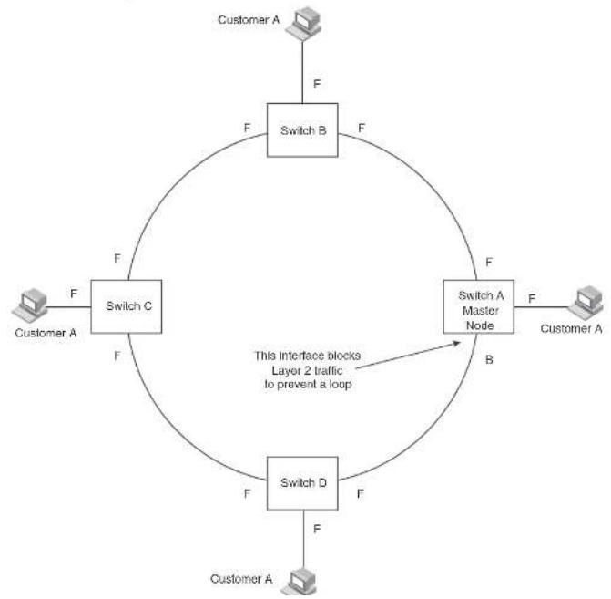
flowchart
graph TD
    A["Customer A"] -->|F| B["Switch B"]
    B -->|F| C["Switch C"]
    C -->|F| D["Switch A Master Node"]
    D -->|F| E["Customer A"]
    E -->|F| F["Switch D"]
    F -->|F| C
    style C fill:#f9f,stroke:#333
    style D fill:#f9f,stroke:#333
    style E fill:#f9f,stroke:#333
    style F fill:#f9f,stroke:#333
    linkStyle 0 stroke:#000,stroke-width:2px
    linkStyle 1 stroke:#000,stroke-width:2px
    linkStyle 2 stroke:#000,stroke-width:2px
    linkStyle 3 stroke:#000,stroke-width:2px
    linkStyle 4 stroke:#000,stroke-width:2px
    linkStyle 5 stroke:#000,stroke-width:2px
    linkStyle 6 stroke:#000,stroke-width:2px
    linkStyle 7 stroke:#000,stroke-width:2px
    linkStyle 8 stroke:#000,stroke-width:2px
    linkStyle 9 stroke:#000,stroke-width:2px
    linkStyle 10 stroke:#000,stroke-width:2px
    linkStyle 11 stroke:#000,stroke-width:2px
    linkStyle 12 stroke:#000,stroke-width:2px
    linkStyle 13 stroke:#000,stroke-width:2px
    linkStyle 14 stroke:#000,stroke-width:2px
    linkStyle 15 stroke:#000,stroke-width:2px
    linkStyle 16 stroke:#000,stroke-width:2px
    linkStyle 17 stroke:#000,stroke-width:2px
    linkStyle 18 stroke:#000,stroke-width:2px
    linkStyle 19 stroke:#000,stroke-width:2px
    linkStyle 20 stroke:#000,stroke-width:2px
Configuration notes
- When you configure MRP, Dell recommends that you disable one of the ring interfaces before beginning the ring configuration. Disabling an interface prevents a Layer 2 loop from occurring while you are configuring MRP on the ring nodes. Once MRP is configured and enabled on all the nodes, you can re-enable the interface.
- The above configurations can be configured as MRP masters or MRP members (for different rings).
MRP rings without shared interfaces (MRP Phase 1)
MRP Phase 1 allows you to configure multiple MRP rings, as shown in Figure 59, but the rings cannot share the same link. For example, you cannot configure ring 1 and ring 2 to each have interfaces 1/1 and 1/2.
Also, when you configure an MRP ring, any node on the ring can be designated as the master node for the ring. A master node can be the master node of more than one ring. (Refer to Figure 59.) Each ring is an independent ring and RHP packets are processed within each ring.
FIGURE 59 Metro ring - multiple rings

flowchart
graph TD
    A["Master Node"] --> B["Ring 1"]
    B --> C["Port1/1"]
    C --> D["Ring 2"]
    D --> E["Port4/1"]
    E --> F["Port4/2"]
    F --> G["Port4/2"]
    G --> H["Port4/2"]
    H --> I["Port4/2"]
    I --> J["Port4/2"]
    J --> K["Port4/2"]
    K --> L["Port4/2"]
    L --> M["Port4/2"]
    M --> N["Port4/2"]
    N --> O["Port4/2"]
    O --> P["Port4/2"]
    P --> Q["Port4/2"]
    Q --> R["Port4/2"]
    R --> S["Port4/2"]
    S --> T["Port4/2"]
    T --> U["Port4/2"]
    U --> V["Port4/2"]
    V --> W["Port4/2"]
    W --> X["Port4/2"]
    X --> Y["Port4/2"]
    Y --> Z["Port4/2"]
MRP rings with shared interfaces (MRP Phase 2)
With MRP Phase 2, MRP rings can be configured to share the same interfaces as long as the interfaces belong to the same VLAN. Figure 60 shows examples of multiple MRP rings that share the same interface.
FIGURE 60 Examples of multiple rings sharing the same interface - MRP Phase 2
Example 1 Example 2

flowchart
graph TD
    A["Port10"] --> B["Ring 1"]
    A --> C["Ring 2"]
    B --> D["Port20"]
    C --> D
    D --> E["Port10"]
    D --> F["Port20"]
    style A fill:#f9f,stroke:#333
    style B fill:#ccf,stroke:#333
    style C fill:#ccf,stroke:#333
    style D fill:#cfc,stroke:#333
    style E fill:#fcc,stroke:#333
    style F fill:#fcc,stroke:#333
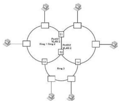
flowchart
graph TD
    A["Router"] --> B["Ring 1"]
    A --> C["Ring 2"]
    B --> D["Router"]
    C --> E["Router"]
    B --> F["Port01 VLAN 2"]
    C --> G["Port02 VLAN 2"]
    B --> H["Port1"]
    C --> I["Port2"]
    B --> J["Ring 3"]
    C --> K["Ring 3"]
    B --> L["Router"]
    C --> M["Router"]
On each node that will participate in the ring, you specify the ring ID and the interfaces that will be used for ring traffic. In a multiple ring configuration, a ring ID determines its priority. The lower the ring ID, the higher priority of a ring.
A ring ID is also used to identify the interfaces that belong to a ring.
FIGURE 61 Interface IDs and types
For example, in Figure 61, the ID of all interfaces on all nodes on Ring 1 is 1 and all interfaces on all nodes on Ring 2 is 2. Port 1/1 on node S1 and Port 2/2 on S2 have the IDs of 1 and 2 since the interfaces are shared by Rings 1 and 2.
The ring ID is also used to determine an interface priority. Generally, a ring ID is also the ring priority and the priority of all interfaces on that ring. However, if the interface is shared by two or more rings, then the highest priority (lowest ID) becomes the priority of the interface. For example, in Figure 61, all interfaces on Ring 1, except for Port 1/1 on node S1 and Port 2/2 on node S2 have a priority of 1. Likewise, all interfaces on Ring 2, except for Port 1/1 on node S1 and Port 2/2 on node S2 have a priority of 2. Port 1/1 on S1 and Port 2/2 on S2 have a priority of 1 since 1 is the highest priority (lowest ID) of the rings that share the interface.
If a node has interfaces that have different IDs, the interfaces that belong to the ring with the highest priority become regular ports. Those interfaces that do not belong to the ring with the highest priority become tunnel ports. In Figure 61, nodes S1 and S2 have interfaces that belong to Rings 1 and 2. Those interfaces with a priority of 1 are regular ports. The interfaces with a priority of 2 are the tunnel ports since they belong to Ring 2, which has a lower priority than Ring 1.
Selection of master node
Allowing MRP rings to share interfaces limits the nodes that can be designated as the master node. Any node on an MRP ring that does not have a shared interface can be designated as the ring master node. However, if all nodes on the ring have shared interfaces, nodes that do not have tunnel ports can be designated as the master node of that ring. If none of the nodes meet these criteria, you must change the rings' priorities by reconfiguring the rings' ID.
In Figure 61, any of the nodes on Ring 1, even S1 or S2, can be a master node since none of its interfaces are tunnel ports. However in Ring 2, neither S1 nor S2 can be a master node since these nodes contain tunnel ports.
Ring initialization
The ring shown in Figure 58 shows the port states in a fully initialized ring without any broken links. Figure 62 shows the initial state of the ring, when MRP is first enabled on the ring switches. All ring interfaces on the master node and member nodes begin in the Preforwarding state (PF).
FIGURE 62 Metro ring – initial state

flowchart
graph TD
    A["Customer A"] -->|F| B["Switch B"]
    B -->|PF PF| C["Switch C"]
    C -->|PF| D["Switch D"]
    D -->|PF| E["Switch A Master Node"]
    E -->|F| F["Customer A"]
    F -->|F| G["Switch B"]
    G -->|PF PF| H["Switch C"]
    H -->|PF| I["Switch D"]
    I -->|PF| J["Switch A"]
    J -->|F| K["Switch B"]
    K -->|PF PF| L["Switch C"]
    L -->|PF| M["Switch D"]
    M -->|PF| N["Switch A Master Node"]
    N -->|PF| O["Switch B"]
    O -->|PF PF| P["Switch C"]
    P -->|PF| Q["Switch D"]
    Q -->|PF| R["Switch A Master Node"]
    R -->|PF| S["Switch B"]
    S -->|PF PF| T["Switch C"]
    T -->|PF PF| U["Switch D"]
    U -->|PF PF| V["Switch A Master Node"]
    V -->|PF PF| W["Switch B"]
    W -->|PF PF| X["Switch C"]
    X -->|PF PF| Y["Switch D"]
    Y -->|PF PF| Z["Switch A Master Node"]
    Z -->|PF PF| AA["Switch B"]
    AA -->|PF PF| AB["Switch C"]
    AB -->|PF PF| AC["Switch D"]
    AC -->|PF PF| AD["Switch A Master Node"]
    AD -->|PF PF| AE["Switch B"]
    AE -->|PF PF| AF["Switch C"]
    AF -->|PF PF| AG["Switch D"]
    AG -->|PF PF| AH["Switch A Master Node"]
    AH -->|PF PF| AI["Switch B"]
    AI -->|PF PF| AJ["Switch C"]
    AJ -->|PF PF| AK["Switch D"]
    AK -->|PF PF| AL["Switch A Master Node"]
    AL -->|PF PF| AM["Switch B"]
    AM -->|PF PF| AN["Switch C"]
    AN -->|PF PF| AO["Switch D"]
    AO -->|PF PF| AP["Switch A Master Node"]
    AP -->|PF PF| AQ["Switch B"]
    AQ -->|PF PF| AR["Switch C"]
    AR -->|PF PF| AS["Switch D"]
    AS -->|PF PF| AT["Switch A Master Node"]
    AT -->|PF PF| AU["Switch B"]
    AU -->|PF PF| AV["Switch C"]
    AV -->|PF PF| AW["Switch D"]
    AW -->|PF PF| AX["Switch A Master Node"]
    AX -->|PF PF| AY["Switch B"]
    AY -->|PF PF| AZ["Switch C"]
    AZ -->|PF PF| BA["Switch D"]
    BA -->|PF PF| BB["Switch A Master Node"]
    BB -->|PF PF| BC["Switch B"]
    BC -->|PF PF| BD["Switch C"]
    BD -->|PF PF| BE["Switch D"]
    BE -->|PF PF| BF["Switch A Master Node"]
    BF -->|PF PF| BG["Switch B"]
    BG -->|PF PF| BH["Switch C"]
    BH -->|PF PF| BI["Switch D"]
    BI -->|PF PF| BJ["Switch A Master Node"]
    BJ -->|PF PF| BK["Switch B"]
    BK -->|PF PF| BL["Switch C"]
    BL -->|PF PF| BM["Switch D"]
    BM -->|PF PF| BN["Switch A Master Node"]
    BN -->|PF PF| BO["Switch B"]
    BO -->|PF PF| BP["Switch C"]
    BP -->|PF PF| BQ["Switch D"]
    BQ -->|PF PF| BR["Switch A Master Node"]
    BR -->|PF PF| BS["Switch B"]
    BS -->|PF PF| BT["Switch C"]
    BT -->|PF PF| BU["Switch D"]
    BU -->|PF PF| BV["Switch A Master Node"]
    BV -->|PF PF| BW["Switch B"]
    BW -->|PF PF| BX["Switch C"]
    BX -->|PF PF| BY["Switch D"]
    BY -->|PF PF| BZ["Switch A Master Node"]
    BZ -->|PF PF| CA["Switch B"]
    CA -->|PF PF| CB["Switch C"]
    CB -->|PF PF| CC["Switch D"]
    CC -->|PF PF| CD["Switch A Master Node"]
    CD -->|PF PF| DE["Switch B"]
- Forwarding (F) – The interface can forward data as well as RHPs. An interface changes from Preforwarding to Forwarding when the port preforwarding time expires. This occurs if the port does not receive an RHP from the Master, or if the forwarding bit in the RHPs received by the port is off. This indicates a break in the ring. The port heals the ring by changing its state to Forwarding. The preforwarding time is the number of milliseconds the port will remain in the Preforwarding state before changing to the Forwarding state, even without receiving an RHP.
- Blocking (B) – The interface cannot forward data. Only the secondary interface on the Master node can be Blocking.
When MRP is enabled, all ports begin in the Preforwarding state. The primary interface on the Master node, although it is in the Preforwarding state like the other ports, immediately sends an RHP onto the ring. The secondary port on the Master node listens for the RHP.
- If the secondary port receives the RHP, all links in the ring are up and the port changes its state to Blocking. The primary port then sends another MRP with its forwarding bit set on. As each of the member ports receives the RHP, the ports changes their state to Forwarding. Typically, this occurs in sub-second time. The ring very quickly enters the fully initialized state.
- If the secondary port does not receive the RHP by the time the preforwarding time expires, a break has occurred in the ring. The port changes its state to Forwarding. The member ports also change their states from Preforwarding to Forwarding as their preforwarding timers expire. The ring is not intact, but data can still travel among the nodes using the links that are up.
Figure 63 shows an example.
FIGURE 63 Metro ring – from preforwarding to forwarding
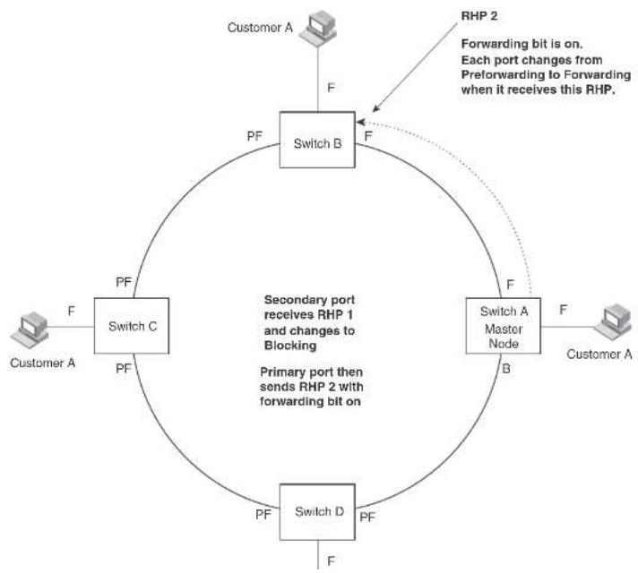
flowchart
graph TD
    A["Switch A"] -->|F| B["Switch B"]
    B -->|F| C["Switch C"]
    C -->|PF| A
    D["Switch A Master Node"] -->|F| B
    E["Switch D"] -->|PF| C
    F["Customer A"] -->|F| A
    G["RHP 2"] -->|Forwarding bit is on. Each port changes from Preforwarding to Forwarding when it receives this RHP.| B
    H["Primary port then sends RHP 1 and changes to Blocking"] --> I["Switch C"]
    I --> J["Switch B"]
    J --> K["Switch D"]
    K --> L["Customer A"]
RHP processing in MRP Phase 2
Figure 64 shows an example of how RHP packets are processed normally in MRP rings with shared interfaces.
FIGURE 64 Flow of RHP packets on MRP rings with shared interfaces

flowchart
graph TD
    A["Master node (primary interface) Port2/1"] -->|1| B["S1"]
    B -->|2| C["Ring 2"]
    C -->|2| D["Ring 3/2 (secondary interface)"]
    D -->|2| E["Ring 4/3 (primary interface)"]
    E -->|2| F["S2"]
    F -->|1| G["S3"]
    G -->|1| H["(secondary interface) Port2/2"]
    H -->|1| I["Ring 1"]
    I -->|1| J["Ring 2"]
    J -->|1| K["Ring 3/4 (secondary interface)"]
    K -->|2| L["Ring 4/3 (primary interface)"]
    L -->|2| M["Ring 5/4 (secondary interface)"]
    M -->|2| N["Ring 6/3 (primary interface)"]
    N -->|2| O["Ring 7/4 (secondary interface)"]
    O -->|2| P["Ring 8/5 (primary interface)"]
    P -->|2| Q["Ring 9/6 (secondary interface)"]
    Q -->|2| R["Ring 10/7 (primary interface)"]
    R -->|2| S["Ring 11/8 (secondary interface)"]
    S -->|2| T["Ring 12/9 (primary interface)"]
    T -->|2| U["Ring 13/10 (secondary interface)"]
    U -->|2| V["Ring 14/11 (primary interface)"]
    V -->|2| W["Ring 15/12 (secondary interface)"]
    W -->|2| X["Ring 16/13 (primary interface)"]
    X -->|2| Y["Ring 17/14 (secondary interface)"]
    Y -->|2| Z["Ring 18/15 (primary interface)"]
    Z -->|2| AA["Ring 19/16 (secondary interface)"]
    AA -->|2| AB["Ring 20/17 (primary interface)"]
    AB -->|2| AC["Ring 21/18 (secondary interface)"]
    AC -->|2| AD["Ring 22/19 (primary interface)"]
    AD -->|2| AE["Ring 23/20 (secondary interface)"]
    AE -->|2| AF["Ring 24/21 (Primary interface)"]
    AF -->|2| AG["Ring 25/22 (Secondary interface)"]
    AG -->|2| AH["Ring 26/23 (Primary interface)"]
    AH -->|2| AI["Ring 27/24 (Secondary interface)"]
    AI -->|2| AJ["Ring 28/25 (Primary interface)"]
    AJ -->|2| AK["Ring 29/26 (Secondary interface)"]
    AK -->|2| AL["Ring 30/27 (Primary interface)"]
    AL -->|2| AM["Ring 31/28 (Secondary interface)"]
    AM -->|2| AN["Ring 32/29 (Primary interface)"]
    AN -->|2| AO["Ring 33/30 (Secondary interface)"]
    AO -->|2| AP["Ring 34/31 (Primary interface)"]
    AP -->|2| AQ["Ring 35/32 (Secondary interface)"]
    AQ -->|2| AR["Ring 36/33 (Primary interface)"]
    AR -->|2| AS["Ring 37/34 (Secondary interface)"]
    AS -->|2| AT["Ring 38/35 (Primary interface)"]
    AT -->|2| AU["Ring 39/36 (Secondary interface)"]
    AU -->|2| AV["Ring 40/37 (Primary interface)"]
    AV -->|2| AW["Ring 41/38 (Secondary interface)"]
    AW -->|2| AX["Ring 42/39 (Primary interface)"]
    AX -->|2| AY["Ring 43/40 (Secondary interface)"]
    AY -->|2| AZ["Ring 44/41 (Primary interface)"]
    AZ -->|2| BA["Ring 45/42 (Secondary interface)"]
    BA -->|2| BB["Ring 46/43 (Primary interface)"]
    BB -->|2| BC["Ring 47/44 (Secondary interface)"]
    BC -->|2| BD["Ring 48/45 (Primary interface)"]
    BD -->|2| BE["Ring 49/46 (Secondary interface)"]
    BE -->|2| BF["Ring 50/47 (Primary interface)"]
    BF -->|2| BG["Ring 51/48 (Secondary interface)"]
    BG -->|2| BH["Ring 52/49 (Primary interface)"]
    BH -->|2| BI["Ring 53/50 (Secondary interface)"]
    BI -->|2| BJ["Ring 54/51 (Primary interface)"]
    BJ -->|2| BK["Ring 55/52 (Secondary interface)"]
    BK -->|2| BL["Ring 56/53 (Primary interface)"]
    BL -->|2| BM["Ring 57/54 (Secondary interface)"]
    BM -->|2| BN["Ring 58/55 (Primary interface)"]
    BN -->|2| BO["Ring 59/56 (Secondary interface)"]
    BO -->|2| BP["Ring 60/57 (Primary interface)"]
    BP -->|2| BQ["Ring 61/58 (Secondary interface)"]
    BQ -->|2| BR["Ring 62/59 (Primary interface)"]
    BR -->|2| CA["Ring 63/60 (Secondary interface)"]
    CA -->|2| CB["Ring 64/61 (Primary interface)"]
    CB -->|2| CC["Ring 65/62 (Secondary interface)"]
    CC -->|2| CD["Ring 66/63 (Primary interface)"]
    CD -->|2| CE["Ring 67/64 (Secondary interface)"]
    CE -->|2| CF["Ring 68/65 (Primary interface)"]
    CF -->|2| CG["Ring 69/66 (Secondary interface)"]
    CG -->|2| CH["Ring 70/67 (Primary interface)"]
    CH -->|2| CI["Ring 71/68 (Secondary interface)"]
    CI -->|2| CJ["Ring 72/69 (Primary interface)"]
    CJ -->|2| CK["Ring 73/70 (Secondary interface)"]
    CK -->|2| CL["Ring 74/71 (Primary interface)"]
    CL -->|2| CM["Ring 75/72 (Secondary interface)"]
    CM -->|2| CN["Ring 76/73 (Primary interface)"]
    CN -->|2| CO["Ring 77/74 (Secondary interface)"]
    CO -->|2| CP["Ring 78/75 (Primary interface)"]
    CP -->|2| CQ["Ring 79/76 (Secondary interface)"]
    CQ -->|2| CR["Ring 80/77 (Primary interface)"]
    CR -->|2| CS["Ring 81/78 (Secondary interface)"]
    CS -->|2| CT["Ring 82/79 (Primary interface)"]
    CT -->|2| CU["Ring 83/80 (Secondary interface)"]
    CU -->|2| CV["Ring 84/81 (Primary interface)"]
    CV -->|2| CW["Ring 85/82 (Secondary interface)"]
    CW -->|2| CX["Ring 86/83 (Primary interface)"]
    CX -->|2| CY["Ring 87/84 (Secondary interface)"]
Port 2/1 on Ring 1 master node is the primary interface of the master node. The primary interface forwards an RHP packet on the ring. Since all the interfaces on Ring 1 are regular ports, the RHP packet is forwarded to all the interfaces until it reaches Port 2/2, the secondary interface of the master node. Port 2/2 then blocks the packet to complete the process.
On Ring 2, Port 3/1, is the primary interface of the master node. It sends an RHP packet on the ring. Since all ports on S4 are regular ports, the RHP packet is forwarded on those interfaces.
How ring breaks are detected and healed
Figure 65 shows ring interface states following a link break. MRP quickly heals the ring and
preserves connectivity among the customer networks.
FIGURE 65 Metro ring - ring break

flowchart
graph TD
    A["Customer A"] -->|F| B["Switch B"]
    B -->|F| C["Switch C"]
    C -->|F| D["Switch A Master Node"]
    D -->|F| E["Customer A"]
    B -->|F| F["Computer"]
- If the interface receives an RHP, the interface changes back to the Blocking state and resets the dead timer.
- If the interface does not receive an RHP for its ring before the Preforwarding time expires, the interface changes to the Forwarding state, as shown in Figure 65.
- Forwarding interfaces – Each member interface remains in the Forwarding state.
When the broken link is repaired, the link interfaces come up in the Preforwarding state, which allows RHPs to travel through the restored interfaces and reach the secondary interface on the Master node:
- If an RHP reaches the Master node secondary interface, the ring is intact. The secondary interface changes to Blocking. The Master node sets the forwarding bit on in the next RHP. When the restored interfaces receive this RHP, they immediately change state to Forwarding.
- If an RHP does not reach the Master node secondary interface, the ring is still broken. The Master node does not send an RHP with the forwarding bit on. In this case, the restored interfaces remain in the Preforwarding state until the preforwarding timer expires, then change to the Forwarding state.
If the link between shared interfaces breaks (Figure 66), the secondary interface on Ring 1 master node changes to a preforwarding state. The RHP packet sent by port 3/1 on Ring 2 is forwarded through the interfaces on S4, then to S2. The packet is then forwarded through S2 to S3, but not from S2 to S1 since the link between the two nodes is not available. When the packet reaches Ring 1 master node, the packet is forwarded through the secondary interface since it is currently in a preforwarding state. A secondary interface in preforwarding mode ignores any RHP packet that is not from its ring. The secondary interface changes to blocking mode only when the RHP packet forwarded by its primary interface is returned.
The packet then continues around Ring 1, through the interfaces on S1 to Ring 2 until it reaches Ring 2 master node. Port 3/2, the secondary interface on Ring 2 changes to blocking mode since it received its own packet, then blocks the packet to prevent a loop.
FIGURE 66 Flow of RHP packets when a link for shared interfaces breaks


Master VLANs and customer VLANs
All the ring ports must be in the same VLAN. Placing the ring ports in the same VLAN provides
Layer 2 connectivity for a given customer across the ring. Figure 67 shows an example.
FIGURE 67 Metro ring - ring VLAN and customer VLANs
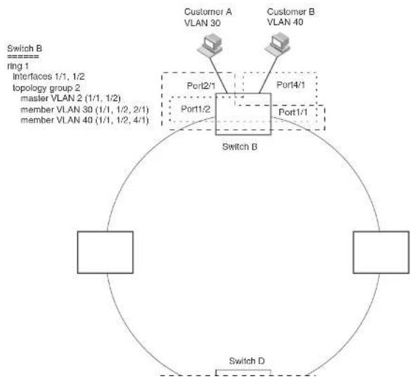
flowchart
graph TD
    A["Switch B\nring 1\nInterfaces 1/1, 1/2\ntopology group 2\nmaster VLAN 2 (1/1, 1/2)\nmember VLAN 30 (1/1, 1/2, 2/1)\nmember VLAN 40 (1/1, 1/2, 4/1)"] --> B["Switch B"]
    B --> C["Port1/2"]
    B --> D["Port1/1"]
    B --> E["Port4/1"]
    B --> F["Port2/1"]
    B --> G["Customer A\nVLAN 30"]
    B --> H["Customer B\nVLAN 40"]
    B --> I["Switch D"]
A topology group enables you to control forwarding in multiple VLANs using a single instance of a Layer 2 protocol such as MRP. A topology group contains a master VLAN and member VLANs. The master VLAN contains all the configuration parameters for the Layer 2 protocol (STP, MRP, or VSRP). The member VLANs use the Layer 2 configuration of the master VLAN.
In Figure 67, VLAN 2 is the master VLAN and contains the MRP configuration parameters for ring 1. VLAN 30 and VLAN 40, the customer VLANs, are member VLANs in the topology group. Since a topology group is used, a single instance of MRP provides redundancy and loop prevention for both the customer VLANs.
If you use a topology group:
- The master VLAN must contain the ring interfaces. The ports must be tagged, since they will be shared by multiple VLANs.
- The member VLAN for a customer must contain the two ring interfaces and the interfaces for the customer. Since these interfaces are shared with the master VLAN, they must be tagged. Do not add another customer interfaces to the VLAN.
For more information about topology groups, refer to "Topology groups" on page 333.
Refer to "MRP CLI example" on page 355 for the configuration commands required to implement the MRP configuration shown in Figure 67.
Configuring MRP
To configure MRP, perform the following tasks. You need to perform the first task on only one of the nodes. Perform the remaining tasks on all the nodes.
NOTE
There are no new commands or parameters to configure MRP with shared interfaces (MRP Phase 2).
- Disable one of the ring interfaces. This prevents a Layer 2 loop from occurring while you are configuring the devices for MRP.
- Add an MRP ring to a port based VLAN. When you add a ring, the CLI changes to the configuration level for the ring, where you can perform the following tasks.
- Optionally specify a name for the ring
Adding an MRP ring to a VLAN
To add an MRP ring to a VLAN, enter commands such as the following.
NOTE
If you plan to use a topology group to add VLANs to the ring, make sure you configure MRP on the topology group master VLAN.
PowerConnect(config)#vlan 2
PowerConnect(config-vlan-2)#metro-ring 1
PowerConnect(config-vlan-2-mrp-1)#namo CustomerA
PowerConnect(config-vlan-2-mrp-1)#master
PowerConnect(config-vlan-2-mrp-1)#ring-interface ethernet 1/1 ethernet 1/2
PowerConnect(config-vlan-2-mrp-1)#enable
These commands configure an MRP ring on VLAN 2. The ring ID is 1, the ring name is CustomerA, and this node (this Dell PowerConnect device) is the master for the ring. The ring interfaces are 1/1 and 1/2. Interface 1/1 is the primary interface and 1/2 is the secondary interface. The primary interface will initiate RHPs by default. The ring takes effect in VLAN 2.
PowerConnect(config)#vlan 2
PowerConnect(config-vlan-2)#metro-ring 1
PowerConnect(config-vlan-2 mrp 1)#name CustomerA
PowerConnect(config-vlan-2-mrp-1)#ring-interface ethernet 1/1 ethernet 1/2
PowerConnect(config-vlan-2-mrp-1)#enable
PowerConnect(config-vlan-2-mrp-1)#metro-ring 2
PowerConnect(config-vlan-2-mrp-2)#tamo CustomerB
PowerConnect(config-vlan-2-mrp-2)#ring-interface ethernet 1/1 ethernet 1/2
PowerConnect(config-vlan-2-mrp-2)#enable
Syntax: [no] metro-ring
The
OnPowerConnect B-Series FCX devices, enter the metro-rings in addition to the metro-ring command as shown below.
PowerConnect(config)#vlan 2
DavonCommsch (confl. 2014)
Configures this node as the master node for the ring. Enter this command only on one node in the ring. The node is a member (non-master) node by default.
Syntax: [no] ring-interface ethernet
The ethernet
The ethernet
NOTE
To take advantage of every interface in a Metro network, you can configure another MRP ring and either configure a different Master node for the ring or reverse the configuration of the primary and secondary interfaces on the Master node. Configuring multiple rings enables you to use all the ports in the ring. The same port can forward traffic one ring while blocking traffic for another ring.
Syntax: [no] enable
The enable command enables the ring.
Changing the hello and preforwarding times
You also can change the RHP hello time and preforwarding time. To do so, enter commands such as the following.
PowerConnect(config-vlan-2-mrp-1)hello-time 200
PowerConnect(config-vlan-2-mrp-1)#preforwarding-time 400
These commands change the hello time to 200 ms and change the preforwarding time to 400 ms.
Syntax: [no] hello-time
Syntax: [no] preforwarding-time
The
Using MRP diagnostics
The MRP diagnostics feature calculates how long it takes for RHP packets to travel through the ring. When you enable MRP diagnostics, the software tracks RHP packets according to their sequence numbers and calculates how long it takes an RHP packet to travel one time through the entire ring. When you display the diagnostics, the CLI shows the average round-trip time for the RHP packets sent since you enabled diagnostics. The calculated results have a granularity of 1 microsecond.
Enabling MRP diagnostics
To enable MRP diagnostics for a ring, enter the following command on the Master node, at the configuration level for the ring.
PowerConnect(config-vlan-2-mrp-1)†diagnostics
Syntax: [no] diagnostics
NOTE
This command is valid only on the master node.
Displaying MRP diagnostics
To display MRP diagnostics results, enter the following command on the Master node.
PowerConnect#show metro 1 diag
Metro Ring 1 - CustomerA
[EMPTY]
diagnostics results
| Ring id | Diag state | RIP average time (microsec) | Recommended hello time (ms) | Recommended Prefwing time (ms) |
| 2 | onabled | 125 | 100 | 300 |
Diag frame sent Diag frame lost
1230
TABLE 61 CLI display of MRP ring diagnostic information (Continued)
| This field... Displays... |
| Diag frame sent The number of diagnostic RHPs sent for the test. |
| Diag frame lost The number of diagnostic RHPs lost during the test. |
If the recommended hello time and preforwarding time are different from the actual settings and you want to change them, refer to "Configuring MRP" on page 349.
Displaying MRP information
You can display the following MRP information:
• Topology group configuration information
• Ring configuration information and statistics
Displaying topology group information
To display topology group information, enter the following command.
Syntax: show topology-group [
Refer to "Displaying topology group information" on page 336 for more information.
Displaying ring information
To display ring information, enter the following command.
PowerConnect/show metro
Metro Ring 1
| Ring id 2 | State enabled | Ring role member | Master vlan 2 | Topo group not conf | Hello time (ms) 100 | Prefwing time (ms) 300 |
TABLE 62 CLI display of MRP ring information
| This field... Displays... | |
| Ring id The ring ID | |
| State The state of MRP. The state can be one of the following: enabled - MRP is enableddisabled - MRP is disabled | |
| Ring role Whether this node is the master for the ring. The role can be one of the following:mastermember | |
| Master vlan The ID of the master VLAN in the topology group used by this ring. If atopology group is used by MRP, the master VLAN controls the MRP settings for all VLANs in the topology group.NOTE: The topology group ID is 0 if the MRP VLAN is not the master VLAN in a topology group. Using a topology group for MRP configuration is optional. | |
| Topo group The topology group ID. | |
| Hello time The interval, In milliseconds, at which the Forwarding port on the ringmaster node sends Ring Hello Packets (RHPs). | |
| Prefwing time The number of milliseconds an MRP interface that has entered the Preforwarding state will wait before changing to the Forwarding state. If a member port in the Preforwarding state does not receive an RHP within the Preforwarding time (Prefwing time), the port assumes that a topology change has occurred and changes to the Forwarding state.The secondary port on the Master node changes to Blocking if it receives an RHP, but changes to Forwarding. If the port does not receive an RHP before the preforwarding time expires.NOTE: A member node Preforwarding interface also changes from Preforwarding to Forwarding if it receives an RHP whose forwarding bit is on. | |
| Ring Interfaces | The device two interfaces with the ring.NOTE: If the interfaces are trunk groups, only the primary ports of the |
TABLE 62 CLI display of MRP ring information (Continued)
| This field... Displays... |
| Active interface The physical interfaces that are sending and receiving RHPs. |
| NOTE: If a port is disabled, its state is shown as "disabled". |
| NOTE: If an interface is a trunk group, only the primary port of the group is listed. |
| Interface Type Shows if the interface is a regular port or a tunnel port. |
| RHPs sent The number of RHPs sent on the interface. |
| NOTE: This field applies only to the master node. On non-master nodes, this field contains 0. This is because the RHPs are forwarded in hardware on the non-master nodes. |
| RHPs rcvd The number of RHPs received on the interface. |
| NOTE: On most Dell PowerConnect devices, this field applies only to the master node. On non-master nodes, this field contains 0. This is because the RHPs are forwarded in hardware on the non-master nodes. However, on the PowerConnect devices, the RHP received counter on non-master MRP nodes increment. This is because, on PowerConnect devices, the CPU receives a copy of the RHPs forwarded in hardware. |
| TC RHPs rcvd The number of Topology Change RHPs received on the Interface. A Topology Change RHP indicates that the ring topology has changed. |
| State changes The number of MRP interface state changes that have occurred. The state can be one of the states listed in the Forwarding state field. |
| Interface Type Shows if the interface is a regular port or a tunnel port. |
MRP CLI example
The following examples show the CLI commands required to implement the MRP configuration shown in Figure 67 on page 348.
NOTE
For simplicity, the figure shows the UI Mio on only two switches. The OI would be implemented at the
The following commands configure the customer VLANs. The customer VLANs must contain both the ring interfaces as well as the customer interfaces.
PowerConnect(config-vlan-30
PowerConnect(config-vlan-30) tag ethernet 1/1 to 1/2
PowerConnect(config-vlan-30) tag ethernet 2/1
PowerConnect(config-vlan-30) exit
PowerConnect(config)#vlan 40
PowerConnect(config-vlan-40) tag ethernet 1/1 to 1/2
PowerConnect(config-vlan-40) tag ethernet 4/1
PowerConnect(config-vlan-40) exit
The following commands configure topology group 1 on VLAN 2. The master VLAN is the one that contains the MRP configuration. The member VLANs use the MRP parameters of the master VLAN. The control interfaces (the ones shared by the master VLAN and member VLAN) also share MRP state.
PowerConnect(config)#topology-group 1
PowerConnect(config-topo-group-1)#master-vlan 2
PowerConnect(config-topo-group-1)#member-vlan 30
PowerConnect(config-topo-group-1)#member-vlan 40
Commands on Switch B
The commands for configuring Switches B, C, and D are similar to the commands for configuring Switch A, with two differences: the nodes are not configured to be the ring master. Omitting the master command is required for non-master nodes.
PowerConnect(config)#vlan 2
PowerConnect(config-vlan-2)#tag ethernet 1/1 to 1/2
PowerConnect(config-vlan-2)#metro-ring 1
PowerConnect(config-vlan-2-mrp-1)#name "Moto A"
PowerConnect(config-vlan-2-mrp-1)#ring-interface ethernet 1/1 ethernet 1/2
PowerConnect(config-vlan-2-mrp-1)#enable
PowerConnect(config-vlan-2)#exit
PowerConnect(config)#vlan 30
PowerConnect(config-vlan-30)#tag ethernet 1/1 to 1/2
PowerConnect(config-vlan-30)#tag ethernet 2/1
PowerConnect(config-vlan-30)#exit
PowerConnect(config)#vlan 30
PowerConnect(config-vlan-30)#tag ethernet 1/1 to 1/2
PowerConnect (config-vlan-30) tag ethernet 2/1
PowerConnect(config-vlan-30)†exit
PowerConnect(config)#vlan 40
PowerConnect(config-vlan-40) tag ethernet 1/1 to 1/2
PowerConnect(config-vlan-40)#tag ethernet 4/1
PowerConnect (config-vlan-40) 4exit
PowerConnect(config)#topology-group 1
PowerConnect(config-topo-group-1)#master-vlan 2
PowerConnect(config-topo-group-1) member-vlan 30
PowerConnect(config-topo-group-1)#member-vlan 40
Commands on Switch D
PowerConnect(config)#vlan 2
PowerConnect(config-vlan-2)#tag ethernet 1/1 to 1/2
PowerConnect(config-vlan-2)#metro-ring
PowerConnect(config-vlan-2-mrp-1)#name "Metro A"
PowerConnect(config-vlan-2-mrp-1)tring-interface ethernet 1/1 ethernet 1/2
PowerConnect(config vlan 2 mrp 1)#enable
PowerConnect(config-vlan-2)#exit
PowerConnect(config)#vlan 30
PowerConnect(config-vlan-30) tag ethernet 1/1 to 1/2
PowerConnect(config-vlan-30) tag ethernet 2/1
PowerConnect(config-vlan-30)4exit
PowerConnect(config)#vlan 40
PowerConnect(config-vlan-40)#tag ethernet 1/1 to 1/2
PowerConnect(config-vlan-40)4Laq ethernet 4/1
PowerConnect(config-vlan-40)ftexit
PowerConnect(config)#topology-group 1
PowerConnect(config-topo-group-1)↑master-vlan 2
PowerConnect(config-topo-group-1)#member-vlan 30
PowerConnect (config-topo-group-1) member-vlan 40
Virtual Switch Redundancy Protocol (VSRP)
FIGURE 68 VSRP mesh – redundant paths for Layer 2 and Layer 3 traffic
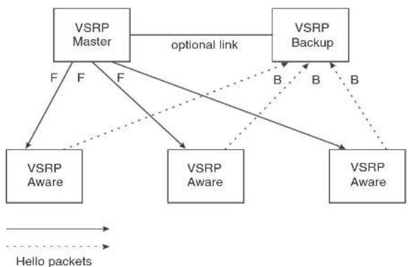
flowchart
graph TD
    A["VSRP Master"] -->|optional link| B["VSRP Backup"]
    A -->|F F F| C["VSRP Aware"]
    A -->|F F| D["VSRP Aware"]
    B -->|B B| E["VSRP Aware"]
    B -->|B B| F["VSRP Backup"]
    C -.-> E
    D -.-> F
    style A fill:#f9f,stroke:#333
    style B fill:#ccf,stroke:#333
    style C fill:#cfc,stroke:#333
    style D fill:#cfc,stroke:#333
    style E fill:#fcc,stroke:#333
    style F fill:#fcc,stroke:#333
    subgraph Hello packets
        direction LR
        A -.-> C
        B -.-> D
        C -.-> E
        D -.-> F
    end
In this example, two Dell PowerConnect devices are configured as redundant paths for VRID 1. On each of the devices, a Virtual Router ID (VRID) is configured on a port-based VLAN. Since VSRP is primarily a Layer 2 redundancy protocol, the VRID applies to the entire VLAN. However, you can selectively remove individual ports from the VRID if needed.
Following Master election (described below), one of the Dell PowerConnect devices becomes the Master for the VRID and sets the state of all the VLAN ports to Forwarding. The other device is a Backup and sets all the ports in its VRID VLAN to Blocking.
If a failover occurs, the Backup becomes the new Master and changes all its VRID ports to the Forwarding state.
Other Dell PowerConnect devices can use the redundant paths provided by the VSRP devices. In
Layer 2 and Layer 3 redundancy
You can configure VSRP to provide redundancy for Layer 2 only or also for Layer 3:
- Layer 2 only – The Layer 2 links are backed up but specific IP addresses are not backed up.
- Layer 2 and Layer 3 – The Layer 2 links are backed up and a specific IP address is also backed up. Layer 3 VSRP is the same as VRRPE. However, using VSRP provides redundancy at both layers at the same time.
Layer 2 Switches support Layer 2 VSRP only. Layer 3 Switches support Layer 2 and Layer 3 redundancy. You can configure a Layer 3 Switch for either Layer 2 only or Layer 2 and Layer 3. To configure for Layer 3, specify the IP address you are backing up.
NOTE
If you want to provide Layer 3 redundancy only, disable VSRP and use VRRPE.
Master election and failover
Each VSRP device advertises its VSRP priority in Hello messages. During Master election, the VSRP device with the highest priority for a given VRID becomes the Master for that VRID. After Master election, the Master sends Hello messages at regular intervals to inform the Backups that the Master is healthy.
If there is a tie for highest VSRP priority, the tie is resolved as follows:
- Layer 2 Switches – The Layer 2 Switch with the higher management IP address becomes the Master.
- Switches with management IP addresses are preferred over switches without management IP addresses.
- If neither of the switches has a management IP address, then the switch with the higher MAC address becomes the Master. (VSRP compares the MAC addresses of the ports configured for the VRID, not the base MAC addresses of the switches.)
- Layer 3 Switches – The Layer 3 Switch whose virtual routing interface has a higher IP address becomes the master.
- If the Backup does not receive a Hello message with a higher priority than its own by the time the hold-down timer expires, the Backup becomes the new Master and starts forwarding Layer 2 traffic on all ports.
If you increase the timer scale value, each timer value is divided by the scale value. To achieve sub-second failover times, you can change the scale to a value up to 10. This shortens all the VSRP timers to 10 percent of their configured values.
VSRP priority calculation
Each VSRP device has a VSRP priority for each VRID and its VLAN. The VRID is used during Master election for the VRID. By default, a device VSRP priority is the value configured on the device (which is 100 by default). However, to ensure that a Backup with a high number of up ports for a given VRID is elected, the device reduces the priority if a port in the VRID VLAN goes down. For example, if two Backups each have a configured priority of 100, and have three ports in VRID 1 in VLAN 10, each Backup begins with an equal priority, 100. This is shown in Figure 69
FIGURE 69 VSRP priority

flowchart
graph TD
    A["VSRP Master"] -->|optional link| B["VSRP Backup"]
    A -->|F F F| A
    B -->|B B B| B
    style A fill:#f9f,stroke:#333
    style B fill:#bbf,stroke:#333
FIGURE 70 VSRP priority recalculation

flowchart
graph TD
    A["VSRP Backup"] -->|B| B["X"]
    A -->|B| C["VSRP Master"]
    A -->|B| D["VSRP Aware"]
    A -->|F| E["VSRP Master"]
    A -->|F| F["VSRP Aware"]
    style A fill:#f9f,stroke:#333
    style B fill:#ccf,stroke:#333
    style C fill:#ccf,stroke:#333
    style D fill:#ccf,stroke:#333
    style E fill:#ccf,stroke:#333
    style F fill:#ccf,stroke:#333
    note1["Configured priority = 100\nActual priority = 100 * (2/3) = 67"] -.-> A
    note2["Configured priority = 100\nActual priority = 100 ^ (3/3) = 100"] -.-> C
    linkDown["Link down"] --> A
You can reduce the sensitivity of a VSRP device to failover by increasing its configured VSRP priority. For example, you can increase the configured priority of the VSRP device on the left in Figure 70 to 150. In this case, failure of a single link does not cause failover. The link failure caused the priority to be reduced to 100, which is still equal to the priority of the other device. This is shown in Figure 71.
FIGURE 71 VSRP priority bias
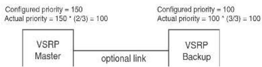
flowchart
graph LR
    A["VS RP Master"] --> B["optional link"]
    B --> C["VS RP Backup"]
    D["Configured priority = 150\nActual priority = 150 * (2/3) = 100"] --> E["Configured priority = 100\nActual priority = 100 ^ (3/3) = 100"]
When you configure a track port, you assign a priority value to the port. If the port goes down, VSRP subtracts the track port priority value from the configured VSRP priority. For example, if the you configure a track port with priority 20 and the configured VSRP priority is 100, the software subtracts 20 from 100 if the track port goes down, resulting in a VSRP priority of 80. The new priority value is used when calculating the VSRP priority. Figure 72 shows an example.
FIGURE 72 Track port priority

flowchart
graph TD
    A["Track port is up"] --> B["VSRP Master"]
    B --> C["optional link"]
    C --> D["VSRP Backup"]
    D --> E["VSRP Aware"]
    D --> F["VSRP Aware"]
    D --> G["VSRP Aware"]
    B --> H["Configured priority = 100\nTrack priority 20\nActual priority = (100 - 0) * (3/3) = 100"]
    D --> I["Configured priority = 100\nActual priority = 100 * (3/3) = 100"]
    B --> J["F"]
    B --> K["F"]
    B --> L["F"]
    D --> M["B"]
    D --> N["B"]
    D --> O["B"]
    E --> P["Dashed arrow to VSRP Aware"]
    F --> Q["Dashed arrow to VSRP Aware"]
    G --> R["Dashed arrow to VSRP Aware"]
In Figure 72, the track port is up. Since the port is up, the track priority does not affect the VSRP priority calculation. If the track port goes down, the track priority does affect VSRP priority calculation, as shown in Figure 73.
FIGURE 73 Track port priority subtracted during priority calculation

flowchart
graph TD
    A["Track link is down"] --> B["VSRP Backup"]
    B --> C["VS R P Master"]
    C --> D["VSRP Aware"]
    C --> E["VSRP Aware"]
    C --> F["VSRP Aware"]
    B --> G["optional link"]
    G --> C
    style A fill:#f9f,stroke:#333
    style B fill:#ccf,stroke:#333
    style C fill:#cfc,stroke:#333
    style D fill:#fcc,stroke:#333
    style E fill:#fcc,stroke:#333
    style F fill:#fcc,stroke:#333
    note1["Configured priority = 100\nTrack priority 20\nActual priority = (100 - 20) * (3/3) = 80"] -.-> B
    note2["Configured priority = 100\nActual priority = 100 * (3/3) = 100"] -.-> C
    B -.->|B| D
    B -.->|B| E
    B -.->|B| F
    C -.->|F| D
    C -.->|F| E
    C -.->|F| F
MAC address failover on VSRP-aware devices
VSRP aware devices maintain a record of each VRID and its VLAN. When the device has received a Hello message for a VRID in a given VLAN, the device creates a record for that VRID and VLAN and includes the port number in the record. Each subsequent time the device receives a Hello message for the same VRID and VLAN, the device checks the port number:
- If the port number is the same as the port that previously received a Hello message, the VSRP-aware device assumes that the message came from the same VSRP Master that sent the previous message.
- If the port number does not match, the VSRP-aware device assumes that a VSRP failover has occurred to a new Master, and moves the MAC addresses learned on the previous port to the new port.
Timer scale
The VSRP Hello interval, Dead interval, Backup Hello interval, and Hold-down interval timers are individually configurable. You also can easily change all the timers at the same time while preserving the ratios among their values. To do so, change the timer scale. The timer scale is a value used by the software to calculate the timers. The software divides a timer value by the timer scale value. By default, the scale is 1. This means the VSRP timer values are the same as the values in the configuration.
VSRP-Aware security features
This feature protects against unauthorized VSRP hello packets by enabling you to configure VSRP-aware security parameters. Without VSRP-aware security, a VSRP-aware device passively learns the authentication method conveyed by the received VSRP hello packet. The VSRP-aware device then stores the authentication method until it ages out with the aware entry.
The VSRP-aware security feature enables you to perform the following:
- Define the specific authentication parameters that a VSRP-aware device will use on a VSRP backup switch. The authentication parameters that you define will not age out.
- Define a list of ports that have authentic VSRP backup switch connections. For ports included in the list, the VSRP-aware switch will process VSRP hello packets using the VSRP-aware security configuration. Conversely, for ports not included in the list, the VSRP-aware switch will not use the VSRP-aware security configuration.
If VSRP hello packets do not meet the acceptance criteria, the VSRP-aware device forwards the packets normally, without any VSRP-aware security processing.
To configure VSRP-Aware Security features, refer to "Configuring security features on a VSRP-aware device" on page 369.
VSRP parameters
Table 63 lists the VSRP parameters.
TINIF 601055
TABLE 63 VSRP parameters (Continued)
| Parameter Description | Default | See page... | |
| Interface parameters | |||
| Authentication type | The type of authentication the VSRP devices use to validate VSRP packets. On Layer 3 Switches, the authentication type must match the authentication type the VRID port uses with other routing protocols such as OSPF.No authentication – The interfaces do not use authentication. This is the VRRP default.Simple – The interface uses a simple text-string as a password in packets sent on the interface. If the interface uses simple password authentication, the VRID configured on the interface must use the same authentication type and the same password.NOTE: MDS is not supported. | No authentication page 369 | |
| VSRP-Aware Security Parameters | |||
| VSRP-Aware Authentication type | The type of authentication the VSRP-aware devices will use on a VSRP backup switch:No authentication – The device does not accept incoming packets that have authentication strings.Simple – The device uses a simple text-string as the authentication string for accepting incoming packets. | Not configured page 369 | |
| VRID parameters | |||
| VSRP device type | Whether the device is a VSRP Backup for the VRID. All VSRP devices for a given VRID are Backups. | Not configured page 367 | |
| VSRP ports The ports in the VRID VLAN that you want to use as VRID interfaces. You can selectively exclude individual ports from VSRP while allowing them to remain in the VLAN. | All ports in the VRID page 370 VLAN | ||
| Parameter | Description | Default | See page... |
| Preference of timer source | When you save a Backup configuration, the software can save the configured VSRP timer values or the VSRP timer values received from the Master.Saving the current timer values instead of the configured ones helps ensure consistent timer usage for all the VRID devices.NOTE: The Backup always gets its timer scale value from the Master. | Configured timer values are saved | page 371 |
| Time-to-Live (TTL) | The maximum number of hops a VSRP Hello packet can traverse before being dropped. You can specify from 1 - 255. | 2 page 372 | |
| Hello interval The amount of time between Hello messages from the Master to the Backups for a given VRID.The interval can be from 1 - 84 seconds. | One second page 372 | ||
| Dead interval The amount of time a Backup waits for a Hello message from the Master for the VRID before determining that the Master is no longer active.If the Master does not send a Hello message before the dead interval expires, the Backups negotiate (compare priorities) to select a new Master for the VRID. | Three times the Hello Interval | page 373 | |
| Backup Hello state and interval | The amount of time between Hello messages from a Backup to the Master.The message interval can be from 60 - 3600 seconds.You must enable the Backup to send the messages.The messages are disabled by default on Backups.The current Master sends Hello messages by default. | Disabled 60 seconds when enabled | page 373 |
| Hold-down interval | The amount of time a Backup that has sent a Hello packet announcing its intent to become Master waits before beginning to forward traffic for the VRID. The hold-down interval prevents Layer 2 loops from | 2 seconds page 374 | |
| Parameter Description Default See page... | |||
| RIP parameters | |||
| Suppression of RIP advertisements | A Layer 3 Switch that is running RIP normally advertises routes to a backed up VRID even when the Layer 3 Switch is not currently the active Layer 3 Switch for the VRID. Suppression of these advertisements helps ensure that other Layer 3 Switches do not receive invalid route paths for the VRID.NOTE: This parameter is valid only on Layer 3 Switches. | Disabled (routes are advertised) | page 375 |
Configuring basic VSRP parameters
To configure VSRP, perform the following required tasks:
- Configure a port-based VLAN containing the ports for which you want to provide VSRP service.
NOTE
If you already have a port-based VLAN but only want to use VSRP on a sub-set of the VLANs ports, you can selectively remove ports from VSRP service in the VLAN. Refer to "Removing a port from the VRID VLAN" on page 370.
- Configure a VRID:
- Specify that the device is a backup. Since VSRP, like VRRPE, does not have an "owner", all VSRP devices are backups. The active device for a VRID is elected based on the VRID priority, which is configurable.
- Activate the VRID.
The following example shows a simple VSRP configuration.
PowerConnect(config)#vlan 200
PowerConnect (config-vlan-200) tag ethernet 1/1 to 1/8
DavonCannari (nonfin=2001) burn void
Syntax: enable | disable
Configuring optional VSRP parameters
The following sections describe how to configure optional VSRP parameters.
Disabling or re-enabling VSRP
VSRP is enabled by default on Layer 2 Switches and Layer 3 Switches. On a Layer 3 Switch, if you want to use VRRP or VRRPE for Layer 3 redundancy instead of VSRP, you need to disable VSRP first. To do so, enter the following command at the global CONFIG level.
PowerConnect(config)#no router vsrp router vsrp is disabled. All vsrp config data will be lost when writing to flash
To re-enable the protocol, enter the following command.
PowerConnect(config)#router verp
Syntax: [no] router vsrp
Since VRRP and VRRPE do not apply to Layer 2 Switches, there is no need to disable VSRP and there is no command to do so. The protocol is always enabled.
Changing the timer scale
To achieve sub-second failover times, you can shorten the duration of all scale timers for VSRP, VRRP, and VRRP-E by adjusting the timer scale. The timer scale is a value used by the software to calculate the timers. By default, the scale value is 1. If you increase the timer scale, each timer value is divided by the scale value. Using the timer scale to adjust timer values enables you to easily change all the timers while preserving the ratios among their values. Here is an example.
Timer Timer scale Timer value
| Hello interval 1 1 second | ||
| 2 | 0 |
To change the timer scale, enter a command such as the following at the global CONFIG level of the CLI.
PowerConnect(config)# scale-timer 2
This command changes the scale to 2. All VSRP, VRRP, and VRRP-E timer values will be divided by 2.
Syntax: [no] scale-timer
The
Configuring authentication
If the interfaces on which you configure the VRID use authentication, the VSRP packets on those interfaces also must use the same authentication. VSRP supports the following authentication types:
- No authentication - The interfaces do not use authentication. This is the default.
- Simple – The interfaces use a simple text-string as a password in packets sent on the interface. If the interfaces use simple password authentication, the VRID configured on the interfaces must use the same authentication type and the same password.
To configure a simple password, enter a command such as the following at the interface configuration level.
PowerConnect(config-if-1/6)#ip vsrp auth-type simple-text-auth ourpword
This command configures the simple text password "ourpword".
Syntax: [no] ip vsrp auth-type no-auth | simple-text-auth
The auth-type no-auth parameter indicates that the VRID and the interface it is configured on do not use authentication.
The auth-type simple-text-auth
Specifying no authentication for VSRP hello packets
The following configuration specifies no authentication as the preferred VSRP-aware security method. In this case, the VSRP device will not accept incoming packets that have authentication strings.
PowerConnect(config)#vlan 10
PowerConnect(config-vlan-10)†varp-aware vrid 2 no-auth
Syntax: vsrp-aware vrid no-auth
The following configuration specifies no authentication for VSRP hello packets received on ports 1/1, 1/2, 1/3, and 1/4 in VRID 4. For these ports, the VSRP device will not accept incoming packets that have authentication strings.
PowerConnect(config)#vlan 10
PowerConnect(config-vlan-10)#varp-aware vrid 4 no-auth port-list ethe 1/1 to 1/4
Syntax: vsrp-aware vrid
no-auth specifies no authentication as the preferred VSRP-aware security method. The VSRP device will not accept incoming packets that have authentication strings.
simple-text-auth
port-list
Removing a port from the VRID VLAN
By default, all the ports on which you configure a VRID are interfaces for the VRID. You can remove a port from the VRID while allowing it to remain in the VLAN.
Removing a port is useful in the following cases:
• There is no risk of a loop occurring, such as when the port is attached directly to an end host.
- You plan to use a port in an MRP ring.
To remove a port from a VRID, enter a command such as the following at the configuration level for
VSRP does not require you to specify an IP address. If you do not specify an address, VSRP provides Layer 2 redundancy. If you do specify an address, VSRP provides Layer 2 and Layer 3 redundancy.
The Layer 3 redundancy support is the same as VRRPE support. For information, refer to Chapter 31, "Configuring VRRP and VRRPE".
NOTE
The VRID IP address must be in the same subnet as a real IP address configured on the VSRP interface, but cannot be the same as a real IP address configured on the interface.
NOTE
Failover applies to both Layer 2 and Layer 3.
To specify an IP address to back up, enter a command such as the following at the configuration level for the VRID.
PowerConnect(config-vlan-200-vrid-1)↑ip-address 10.10.10.1
Syntax: [no] lp-address
Changing the backup priority
When you enter the backup command to configure the device as a VSRP Backup for the VRID, you also can change the backup priority and the track priority:
- The backup priority is used for election of the Master. The VSRP Backup with the highest priority value for the VRID is elected as the Master for that VRID. The default priority is 100. If two or more Backups are tied with the highest priority, the Backup with the highest IP address becomes the Master for the VRID.
- The track priority is used with the track port feature. Refer to "VSRP priority calculation" on page 360 and "Changing the default track priority" on page 374.
To change the backup priority, enter a command such as the following at the configuration level for the VRID.
PowerConnect(config-vlan-200-vrid-1) backup priority 75
- Hold-down interval
By default, each Backup saves the configured timer values to its startup-config file when you save the device configuration.
You can configure a Backup to instead save the current timer values received from the Master when you save the configuration. Saving the current timer values instead of the configured ones helps ensure consistent timer usage for all the VRID devices.
NOTE
The Backups always use the value of the timer scale received from the Master, regardless of whether the timer values that are saved in the configuration are the values configured on the Backup or the values received from the Master.
To configure a Backup to save the VSRP timer values received from the Master instead of the timer values configured on the Backup, enter the following command.
PowerConnect(config vlan-200-vrid-1)#save current values
Syntax: [no] save-current-values
Changing the Time-To-Live (TTL)
A VSRP Hello packet TTL specifies how many hops the packet can traverse before being dropped. A hop can be a Layer 3 Switch or a Layer 2 Switch. You can specify from 1 - 255. The default TTL is 2. When a VSRP device (Master or Backup) sends a VSRP HEIlo packet, the device subtracts one from the TTL. Thus, if the TTL is 2, the device that originates the Hello packet sends it out with a TTL of 1. Each subsequent device that receives the packet also subtracts one from the packet TTL. When the packet has a TTL of 1, the receiving device subtracts 1 and then drops the packet because the TTL is zero.
NOTE
An MRP ring is considered to be a single hop, regardless of the number of nodes in the ring.
To change the TTL for a VRID, enter a command such as the following at the configuration level for the VRID.
NOTE
The default Dead interval is three times the Hello interval plus one-half second. Generally, if you change the Hello interval, you also should change the Dead interval on the Backups.
NOTE
If you change the timer scale, the change affects the actual number of seconds.
Changing the dead interval
The Dead interval is the number of seconds a Backup waits for a Hello message from the Master before determining that the Master is dead. The default is 3 seconds. This is three times the default Hello interval.
To change the Dead interval, enter a command such as the following at the configuration level for the VRID.
PowerConnect(config-vlan-200-vrid-1)#dead-interval 30
Syntax: [no] dead-interval
The
NOTE
If you change the timer scale, the change affects the actual number of seconds.
Changing the backup hello state and interval
By default, Backups do not send Hello messages to advertise themselves to the Master. You can enable these messages if desired and also change the message interval.
To enable a Backup to send Hello messages to the Master, enter a command such as the following at the configuration level for the VRID.
PowerConnect(config-vlan-200-vrid-1)#advertise backup
Changing the hold-down interval
The hold-down interval prevents Layer 2 loops from occurring during failover, by delaying the new Master from forwarding traffic long enough to ensure that the failed Master is really unavailable.
To change the Hold-down interval, enter a command such as the following at the configuration level for the VRID.
PowerConnect(config-vlan-200-vrid-1)thold-down-interval 4
Syntax: [no] hold-down-interval
The
NOTE
If you change the timer scale, the change affects the actual number of seconds.
Changing the default track priority
When you configure a VRID to track the link state of other interfaces, if one of the tracked interface goes down, the software changes the VSRP priority of the VRID interface.
The software reduces the VRID priority by the amount of the priority of the tracked interface that went down. For example, if the VSRP Interface priority is 100 and a tracked interface with track priority 60 goes down, the software changes the VSRP interface priority to 40. If another tracked interface goes down, the software reduces the VRID priority again, by the amount of the tracked interface track priority.
The default track priority for all track ports is 1. You can change the default track priority or override the default for an individual track port.
• To change the default track priority, use the backup track-priority command, described below.
- To override the default track priority for a specific track port, use the track-port command. Refer to "Specifying a track port" on page 374.
To change the track priority, enter a command such as the following at the configuration level for the VRID.
NOTE
The priority
Disabling or re-enabling backup pre-emption
By default, a Backup that has a higher priority than another Backup that has become the Master can preempt the Master, and take over the role of Master. If you want to prevent this behavior, disable preemption.
Preemption applies only to Backups and takes effect only when the Master has failed and a Backup has assumed ownership of the VRID. The feature prevents a Backup with a higher priority from taking over as Master from another Backup that has a lower priority but has already become the Master of the VRID.
Preemption is especially useful for preventing flapping in situations where there are multiple Backups and a Backup with a lower priority than another Backup has assumed ownership, because the Backup with the higher priority was unavailable when ownership changed.
If you enable the non-preempt mode (thus disabling the preemption feature) on all the Backups, the Backup that becomes the Master following the disappearance of the Master continues to be the Master. The new Master is not preempted.
To disable preemption on a Backup, enter a command such as the following at the configuration level for the VRID.
PowerConnect(config-vlan-200-vrid-1) non-preempt-mode
Syntax: [no] non-preempt-mode
Suppressing RIP advertisement from backups
Normally, for Layer 3 a VSRP Backup includes route information for a backed up IP address in RIP advertisements. As a result, other Layer 3 Switches receive multiple paths for the backed up interface and might sometimes unsuccessfully use the path to the Backup rather than the path to
VSRP-aware interoperability
The vsrp-aware tc-vlan-flush command should be used in network configurations in which the Dell PowerConnect switch operates as the VSRP-Aware device connecting to a other devices as a VSRP Master.
The command is available at the VLAN level, and is issued per a specific VRID, as shown here for VRID 11.
PowerConnect(config-vlan-10)↑vsrp-aware vrid 11 tc-vlan-flush
Syntax: vsrp-aware vrid
When this command is enabled, MAC addresses will be flushed at the VLAN level, instead of at the port level. MAC addresses will be flushed for every topology change (TC) received on the VSRP-aware ports.
When this command is enabled, the results of the show vsrp-aware vlan command resemble the following.
PowerConnect(config-vlan-10)#varp-aware vrid 11 tc vlan flush PowerConnect(config-vlan-10)#show vsrp aware vlan 10 Aware Port Listing
VLAN ID VRTB Last Port Auth Type Mac-Flush Age 10 11 N/A no-auth Configured Enabled 00:00:00.0
Displaying VSRP information
You can display the following VSRP information:
- Configuration information and current parameter values for a VRID or VLAN
- The interfaces on a VSRP-aware device that are active for the VRID
Displaying VRID information
To display VSRP information, enter the following command.
This display shows the following information when you use the vrid
TABLE 64 CLI display of VSRP VRID or VLAN information
| This field... Displays... | |
| Total number of VSRP routers defined | The total number of VRIDs configured on this device. |
| VLAN The VLAN on which VSRP is configured. | |
| auth-type The authentication type in effect on the ports in the VSRP VLAN. | |
| VRID parameters | |
| VRID The VRID for which the following information is displayed. | |
| state This device VSRP state for the VRID. The state can be one of the following:initialize - The VRID is not enabled (activated). If the state remains "initialize" after you activate the VRID, make sure that the VRID is also configured on the other routers and that the routers can communicate with each other.NOTE: If the state is "initialize" and the mode is incomplete, make sure you have specified the IP address for the VRID.standby - This device is a Backup for the VRID.master - This device is the Master for the VRID. | |
| Administrative-status The administrative status of the VRID. The administrative status can be one of the following:disabled - The VRID is configured on the interface but VSRP or VRRPE has not been activated on the interface.enabled - VSRP has been activated on the interface. | |
| Advertise-backup Whether the device is enabled to send VSRP Hello messages when it is a Backup.This field can have one of the following values:disabled - The device does not send Hello messages when it is a Backup.enabled - The device does send Hello messages when it is a Backup. | |
| This field... | Displays... |
| dead-interval The configured value for the dead interval. The dead interval is the number of seconds a Backup waits for a Hello message from the Master for the VRID before determining that the Master is no longer active.If the Master does not send a Hello message before the dead interval expires, the Backups negotiate (compare priorities) to select a new Master for the VRID.NOTE: If the value is 0, then you have not configured this parameter. | |
| hold-interval The number of seconds a Backup that intends to become the Master will wait before actually beginning to forward Layer 2 traffic for the VRID.If the Backup receives a Hello message with a higher priority than its own before the hold-down interval expires, the Backup remains in the Backup state and does not become the new Master. | |
| initial-III The number of hops a Hello message can traverse after leaving the device before the Hello message is dropped.NOTE: An MRP ring counts as one hop, regardless of the number of nodes in the ring. | |
| next hello sent In The amount of time until the Master dead Interval expires. If the Backup does not receive a Hello message from the Master by the time the interval expires, either the IP address listed for the Master will change to the IP address of the new Master, or this Layer 3 Switch itself will become the Master.NOTE: This field applies only when this device is a Backup. | |
| Member ports The ports in the VRID. | |
| Operational ports The member ports that are currently up. | |
| Forwarding ports The member ports that are currently in the Forwarding state. Ports that are forwarding on the Master are listed. Ports on the Standlay, which are in the Blocking state, are not listed. | |
Displaying the active interfaces for a VRID
On a VSRP-aware device, you can display VLAN and port information for the connections to the VSRP devices (Master and Backups).
TABLE 65 CLI display of VSRP-aware information (Continued)
| This field... Displays... | |
| VRID The VRID. | |
| Last Port | The most recent active port connection to the VRID. This is the port connected to the current Master. If a fallover occurs, the VSRP-aware device changes the port to the port connected to the new Master. The VSRP-aware device uses this port to send and receive data through the backed up node. |
VSRP fast start
VSRP fast start allows non-Dell PowerConnect or non-VSRP aware devices that are connected to a Dell PowerConnect device that is the VSRP Master to quickly switchover to the new Master when a VSRP fallover occurs
This feature causes the port on a VSRP Master to restart when a VSRP failover occurs. When the port shuts down at the start of the restart, ports on the non-VSRP aware devices that are connected to the VSRP Master flush the MAC address they have learned for the VSRP master. After a specified time, the port on the previous VSRP Master (which now becomes the Backup) returns back online. Ports on the non-VSRP aware devices switch over to the new Master and learn its MAC address.
Configuring VSRP fast start
The VSRP fast start feature can be enabled on a VSRP-configured Dell PowerConnect device, either on the VLAN to which the VRID of the VSRP-configured device belongs (globally) or on a port that belongs to the VRID.
To globally configure a VSRP-configured device to shut down its ports when a failover occurs, then restart after five seconds, enter the following command.
PowerConnect(configure)#vlan 100 PowerConnect(configure-vlan-100)#vsrp vrid 1 PowerConnect(configure-vlan-100-vrid-1)#restart-ports 5
Syntax: [no] restart-ports
PowerConnect+show vsrp wrid 100
VLAN 100
auth-type no authentication
VRID 100
----.
State Administrative-status Advertise-backup Preempt-mode save-current
master enabled disabled true false
Parameter Configured Current Unit/Formula
priority 100 50 (100-0)*(2.0/4.0)
hello-interval 1 1 sec/1
dead-interval 3 3 sec/1
hold-interval 3 3 sec/1
initial-tll 2 2 hops
next hello sent in 00:00:00.3
Member ports: ethe 2/5 to 2/8
Operational ports: elhe 2/5 elhe 2/8
Forwarding ports: ethe 2/5 ethe 2/8
Restart ports: 2/5(1) 2/6(1) 2/7(1) 2/8(1)
The "Restart ports:" line lists the ports that have the VSRP fast start enabled, and the downtime for each port. Refer to Table 64 on page 377 to interpret the remaining information on the display.
VSRP and MRP signaling
A device may connect to an MRP ring through VSRP to provide a redundant path between the device and the MRP ring. VSRP and MRP signaling ensures rapid failover by flushing MAC addresses appropriately. The host on the MRP ring learns the MAC addresses of all devices on the MRP ring and VSRP link. From these MAC addresses, the host creates a MAC database (table), which is used to establish a data path from the host to a VSRP-linked device. Figure 74 below shows two possible data paths from the host to Device 1.
FIGURE 74 Two data paths from host on an MRP ring to a VSRP-linked device
FIGURE 75 VSRP on MRP rings that failed over
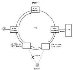
flowchart
graph TD
    A["User"] --> B["NTP Member"]
    B --> C{NTP Master}
    C --> D["Control"]
    D --> E["User"]
    E --> F["Control"]
    F --> G["NTP Member NTP Member"]
    G --> H{NTP Master}
    H --> I["User"]
    I --> J{NTP Member NTP Member}
    J --> K{NTP Master}
    K --> L["User"]
    L --> M["Control"]
    M --> N{NTP Master}
    N --> O["User"]
    O --> P["Control"]
    P --> Q{NTP Master}
    Q --> R["User"]
    R --> S["Control"]
    S --> T{NTP Master}
    T --> U["User"]
    U --> V["Control"]
    V --> W{NTP Master}
    W --> X["User"]
    X --> Y["Control"]
    Y --> Z{NTP Master}
    Z --> AA["User"]
    AA --> AB["Control"]
    AB --> AC{NTP Master}
    AC --> AD["User"]
    AD --> AE["Control"]
    AE --> AF{NTP Master}
    AF --> AG["User"]
    AG --> AH["Control"]
    AH --> AI{NTP Master}
    AI --> AJ["User"]
    AJ --> AK["Control"]
    AK --> AL{NTP Master}
    AL --> AM["User"]
    AM --> AN["Control"]
    AN --> AO{NTP Master}
    AO --> AP["User"]
    AP --> AQ["Control"]
    AQ --> AR{NTP Master}
    AR --> AS["User"]
    AS --> AT["Control"]
    AT --> AU{NTP Master}
    AU --> AV["User"]
    AV --> AW["Control"]
    AW --> AX{NTP Master}
    AX --> AY["User"]
    AY --> AZ["Control"]
    AZ --> BA{NTP Master}
    BA --> BB["User"]
    BB --> BC["Control"]
    BC --> BD{NTP Master}
    BD --> BE["User"]
    BE --> BF["Control"]
    BF --> BG{NTP Master}
    BG --> BH["User"]
    BH --> BI["Control"]
    BI --> BJ{NTP Master}
    BJ --> BK["User"]
    BK --> BL["Control"]
    BL --> BM{NTP Master}
    BM --> BN["User"]
    BN --> BO["Control"]
    BO --> BP{NTP Master}
    BP --> BQ["User"]
    BQ --> BR["Control"]
    BR --> BS{NTP Master}
    BS --> BT["User"]
    BT --> BU["Control"]
    BU --> BV{NTP Master}
    BV --> BW["User"]
    BW --> BX["Control"]
    BX --> BY{NTP Master}
    BY --> BZ["User"]
    BZ --> CA["Control"]
    CA --> CB{NTP Master}
    CB --> CC["User"]
    CC --> CD["Control"]
    CD --> CE{NTP Master}
    CE --> CF["User"]
    CF --> CG["Control"]
    CG --> CH{NTP Master}
    CH --> CI["User"]
    CI --> CJ["Control"]
    CJ --> CK{NTP Master}
    CK --> CL["User"]
    CL --> CM["Control"]
    CM --> CN{NTP Master}
    CN --> CO["User"]
    CO --> CP["Control"]
    CP --> CQ{NTP Master}
    CQ --> CR["User"]
    CR --> CS["Control"]
    CS --> CT{NTP Master}
    CT --> CU["User"]
    CU --> CV["Control"]
    CV --> CW{NTP Master}
    CW --> CX["User"]
    CX --> CY["Control"]
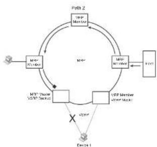
flowchart
graph TD
    A["User"] --> B["MTR Member"]
    B --> C["MTR Reader"]
    C --> D["Node 1"]
    D --> E["Node 2"]
    E --> F["User"]
    F --> G["Node 2"]
    G --> H["User"]
    H --> I["Node 2"]
    I --> J["User"]
    J --> K["Node 2"]
    K --> L["User"]
    L --> M["Node 2"]
    M --> N["User"]
    N --> O["Node 2"]
    O --> P["User"]
    P --> Q["Node 2"]
    Q --> R["User"]
    R --> S["Node 2"]
    S --> T["User"]
    T --> U["Node 2"]
    U --> V["User"]
    V --> W["Node 2"]
    W --> X["User"]
    X --> Y["Node 2"]
    Y --> Z["User"]
    Z --> A
A signaling process for the interaction between VSRP and MRP ensures that MRP is informed of the topology change and achieves convergence rapidly. When a VSRP node fails, a new VSRP master is selected. The new VSRP master finds all MRP instances impacted by the failover. Then each MRP instance does the following:
- The MRP node sends out an MRP PDU with the mac-flush flag set three times on the MRP ring.
- The MRP node that receives this MRP PDU empties all the MAC entries from its interfaces that participate on the MRP ring.
- The MRP node then forwards the MRP PDU with the mac-flush flag set to the next MRP node that is in forwarding state.
The process continues until the Master MRP node secondary (blocking) interface blocks the packet. Once the MAC address entries have been flushed, the MAC table can be rebuilt for the new path from the host to the VSRP-linked device (Figure 76).
FIGURE 76 New path established
PmIn 1
Path 2
Configuring Uni-Directional Link Detection (UDLD) and Protected Link Groups
Chapter
11
Table 66 lists the individual Dell PowerConnect switches and the UDLD and protected link group features they support. These features are supported in the Layer 2, base Layer 3, edge Layer 3, and full Layer 3 software images, except where explicitly noted.
TABLE 66 Supported UDLD and protected link group features
| Feature PowerConnect B-Series FCX | |
| Uni-directional Link Detection (UDLD) | Yes |
| (Link keepalive) | |
| UDLD on tagged ports Yes | |
| Protected link groups Yes | |
UDLD overview
Uni-Directional Link Detection (UDLD) monitors a link between two Dell PowerConnect devices and brings the ports on both ends of the link down if the link goes down at any point between the two devices. This feature is useful for links that are individual ports and for trunk links. Figure 77 shows an example.
FIGURE 77 UDLD example
Without link keepalive, the ports remain
enabled. Traffic continues to be load balanced to the
Normally, a Dell PowerConnect device load balances traffic across the ports in a trunk group. In this example, each Dell PowerConnect device load balances traffic across two ports. Without the UDLD feature, a link failure on a link that is not directly attached to one of the Dell PowerConnect devices is undetected by the Dell PowerConnect devices. As a result, the Dell PowerConnect devices continue to send traffic on the ports connected to the failed link.
When UDLD is enabled on the trunk ports on each Dell PowerConnect device, the devices detect the failed link, disable the ports connected to the failed link, and use the remaining ports in the trunk group to forward the traffic.
Ports enabled for UDLD exchange proprietary health check packets once every second (the keepalive interval). If a port does not receive a health-check packet from the port at the other end of the link within the keepalive interval, the port waits for two more intervals. If the port still does not receive a health-check packet after waiting for three intervals, the port concludes that the link has failed and takes the port down.
UDLD for tagged ports
The default implementation of UDLD sends the packets untagged, even across tagged ports. If the untagged UDLD packet is received by a third-party switch, that switch may reject the packet. As a result, UDLD may be limited only to Dell PowerConnect devices, since UDLD may not function on third-party switches.
To solve this issue, you can configure ports to send out UDLD control packets that are tagged with a specific VLAN ID. This feature also enables third party switches to receive the control packets that are tagged with the specified VLAN. For tagged operation, all of the following conditions must be met:
• A VLAN is specified when UDLD is configured
• The port belongs to the configured VLAN as tagged member
- All the devices across the UDLD link are in the same VLAN
For configuration details, refer to "Enabling UDLD for tagged ports" on page 385.
Configuration notes and feature limitations
Enabling UDLD
NOTE
This section shows how to configure UDLD for untagged control packets. To configure UDLD for tagged control packets, refer to "Enabling UDLD for tagged ports".
To enable UDLD on a port, enter a command such as the following at the global CONFIG level of the CLI.
PowerConnect(config)#link-keepalive ethernet 0/1/1
To enable the feature on a trunk group, enter commands such as the following.
PowerConnect(config)#link-keepalive ethernet 0/1/1 ethernet 0/1/2
PowerConnect (config) + link-keepative ethernet. 0/1/3 ethernet. 0/1/4
Syntax: [no] link-keepalive ethernet
Specify the
• PowerConnect B-Series FCX stackable switches -
Enabling UDLD for tagged ports
To enable ports to receive and send UDLD control packets tagged with a specific VLAN ID, enter commands such as the following.
PowerConnect(config)#link-keepalive ethernet 1/18 vlan 22
This command enables UDLD on port 1/18 and allows UDLD control packet tagged with VLAN 22 to be received and sent on port 1/18.
Syntax: [no] link-keepalive ethernet
Specify the
• PowerConnect B-Series FCX stackable switches -
For the
Changing the Keepalive retries
By default, a port waits one second to receive a health-check reply packet from the port at the other end of the link. If the port does not receive a reply, the port tries four more times by sending up to four more health-check packets. If the port still does not receive a reply after the maximum number of retries, the port goes down.
You can change the maximum number of keepalive attempts to a value from 3 - 64. To change the maximum number of attempts, enter a command such as the following.
PowerConnect(config)#link-keepalive retries 4
Syntax: [no] link-keepalive retries
The
Displaying UDLD information
This section describes the commands used to display information about a UDLD configuration.
Displaying information for all ports
To display UDLD information for all ports, enter the following command.
PowerConnect#show link-keepalive
Total link-keepalive enabled ports: 4
Keepalive Retries: 3 Keepalive Interval: 1 Soc.
| Port | Physical Link | Logical Link | State | Link-vlan |
| 4/1 | up | up | FORWARDING | 3 |
| 4/2 | up | up | FORWARDING | |
| 4/3 | down | down | DISABLED | |
| 4/4 | up | down | DISABLED |
Syntax: show link-keepalive
If a port is disabled by UDLD, the change also is indicated in the output of the show interfaces brief command. An example is given below.
PowerConnect#show interfaces brief
| Port | Link | State | Dup1 | Speed | Trunk | Tag | Priori MAC | Name |
| 1/1 | Up | LK DISABLE | None | None | None | No | level0 00e0.52a9.bb00 | |
| 1/2 | Down | None | None | None | None | No | level0 00e0.52a9.bb01 | |
| 1/3 | Down | None | None | None | None | No | level0 00e0.52a9.bb02 | |
| 1/4 | Down | None | None | None | None | No | level0 00e0.52a9.bb03 |
If the port was already down before you enabled UDLD for the port, the port state is listed as None.
Syntax: show interfaces brief
Displaying information for a single port
To display detailed UDLD information for a specific port, enter a command such as the following.
PowerConnect+show link-keepalive ethernet 4/1
| Current State : up | Remote MAC Addr : 00e0.52d2.5100 |
| Local Port : 4/1 | Remote Port : 2/1 |
| Local System ID : e0927430 | Remote System ID : e0d25100 |
| Packets sent : 254 | Packets received : 255 |
| Transitions : 1 | Link-vlan : 100 |
| Port blocking : No | DM disabled : No |
Syntax: show link-keepalive [ethernet [
TABLE 68 CLI display of detailed UDLD information
This field... Displays...
Current State The state of the logical link. This is the link between this Dell PowerConnect port and the Dell PowerConnect port on the other end of the link.
The show interface ethernet command also displays the UDLD state for an individual port. In addition, the line protocol state listed in the first line will say "down" if UDLD has brought the port down. An example is given below.
PowerConnect#show interface ethernet 1/1
FastEthernet1/1 is down, line protocol is down, link keepalive is enabled
Hardware is FastEthernet, address is 00e0.52a9.bbca (bia 00e0.52a9.bbca)
Configured speed auto, actual unknown, configured duplex fdx, actual unknown
Member of L2 VLAN ID 1, port is untagged, port state is DISABLED
STP configured to ON, priority is level0, flow control enabled
mirror disabled, monitor disabled
Not member of any active trunks
Not member of any configured trunks
No port name
300 second input rate: 0 bits/sec, 0 packets/sec, 0.00% utilization
300 second output rate: 0 bits/sec, 0 packets/sec, 0.00% utilization
0 packets input, 0 bytes, 0 no buff
Received 0 broadcasts, 0 multicasts, 0 unicasts
0 input errors, 0 CRC, 0 frame, 0 ignored
0 runts, 0 giants, EMA received 0 packets
19 packets output, 1216 bytes, 0 underruns
Transmitted 0 broadcasts, 19 multicasts, 0 unicasts
0 output errors, 0 collisions, DMA transmitted 19 packets
In this example, the port has been brought down by UDLD. Notice that in addition to the information in the first line, the port state on the fourth line of the display is listed as DISABLED.
Clearing UDLD statistics
To clear UDLD statistics, enter the following command.
PowerConnect#clear link-keepalive statistics
Syntax: clear link-keepalive statistics
This command clears the Packets sent, Packets received, and Transitions counters in the show link keepalive ethernet [
About active ports
When you create a protected link group, you can optionally specify which port in the protected link group is the active port. If you do not explicitly configure an active port, the Dell PowerConnect device dynamically assigns one. A dynamic active port is the first port in the protected link group that comes up (usually the lowest numbered port in the group).
Static and dynamic active ports operate as follows:
- A static active port (an active port that you explicitly configured) pre-empts other ports in the protected link group. So, if a static active link comes back up after a failure, the Dell PowerConnect device will revert to this link as the active link.
- A dynamic active port (an active port assigned by the software) is non-pre-emptive. Therefore, if a dynamic active link comes back up after a failure, the Dell PowerConnect device does not revert to this link, but continues carrying traffic on the current active link.
Using UDLD with protected link groups
You can use UDLD with protected link groups to detect uni-directional link failures and to improve the speed at which the device detects a failure in the link.
NOTE
When UDLD and protected links are configured on a port and the link goes down, protected links will not come up after UDLD becomes "healthy" again without first physically disabling then re-enabling the link.
Configuration notes
- You can configure a maximum of 32 protected link groups.
• There is no restriction on the number of ports in a protected link group.
• Each port can belong to one protected link group at a time.
• PowerConnect B-Series FCX Series devices support protected link groups consisting of Gbps fibers, parts, 10/100/1000 connector parts, and 10/100 parts, or any combination thereof. These
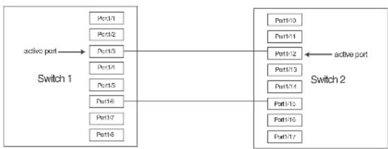
flowchart
graph LR
    A["active port"] --> B["Switch 1"]
    B --> C["Port1/1"]
    B --> D["Port1/2"]
    B --> E["Port1/3"]
    B --> F["Port1/4"]
    B --> G["Port1/5"]
    B --> H["Port1/6"]
    B --> I["Port1/7"]
    B --> J["Port1/8"]
    C --> K["Switch 2"]
    D --> K
    E --> K
    F --> K
    G --> K
    H --> K
    I --> K
    J --> K
    K --> L["Port1/10"]
    K --> M["Port1/11"]
    K --> N["Port1/12"]
    K --> O["Port1/13"]
    K --> P["Port1/14"]
    K --> Q["Port1/15"]
    K --> R["Port1/16"]
    K --> S["Port1/17"]
The configuration for the above illustration is as follows.
Switch 1
PowerConnect(config)# protected-link-group 1 e 1/3 e 1/6
PowerConnect(config)# protected-link-group 1 active-port e 1/3
Switch 2
PowerConnect(config)# protected-link-group 1 e 1/12 e 1/15
PowerConnect(config)# protected-link-group 1 active-port e 1/12
Creating a protected link group and assigning an active port
Follow the steps given below to create a protected link group.
- Specify the member ports in the protected link group. Enter a command such as the following.
PowerConnect(config)#protected-link-group 10 e 1 to 4
- Optionally specify which port will be the active port for the protected link group. Enter a command such as the following.
PowerConnect (config) #protected-link-group 10 active-port e 1
The
The active-port ethernet
• PowerConnect B-Series FCX stackable switches -
Viewing information about protected link groups
You can use the following show commands to view information about protected link groups:
• show protected-link-group
• show interface brief
• show interface
The following shows example output for the show protected-link-group command.
PowerConnect#show protected-link-group
Group ID: 1
Member Port(s): ethe 1 to 7
Configured Active Port: 7
Current Active Port: 7
Standby Port (a): ethe 5
Total Number of Protected Link Groups: 1
Syntax: show protected-link-group [
TABLE 69 CLI display of protected link group information
| This field... Displays... | |
| Group ID The ID number of the protected link group. | |
| Member Port(s) The ports that are members of the protected link group. | |
| Configured Active Port | The statically configured active port. If you do not statically configure an active port, this value will be "None". |
| Current Active Port The current active port for the protected link group. If all member ports are down, this value will be "None". | |
Standby Port(s) The member ports that are on standby.
PowerConnect#show int e 3
GigabitEthernet3 is up, line protocol is up, link keepalive is enabled Hardware is GigabitEthernet, address is 0012.f2a8.7140 (s1a 0012.f2a8.7162) Configured speed auto, actual l8bit, configured duplex fdx, actual fdx Configured mdi mode AUTO, actual MDIX
Member of 3 L2 VLANs, port is tagged, port state is protected-link-inactive EPDU guard is Disabled, BOOT protect is Disabled Link Error Dampening is Disabled STP configured to ON, priority is level0 ...
some times committed for brevity
In the above output, the port state is protected-link-inactive which means port 3 is an inactive port in a protected link group.
Syntax: show interface ethernet
Specify the
• PowerConnect B-Series FCX stackable switches -
Configuring Trunk Groups and Dynamic Link Aggregation
Chapter
Table 70 lists the individual Dell PowerConnect switches and the trunk groups and dynamic link aggregation features they support.
TABLE 70 Supported trunk group and dynamic link aggregation features
| Feature PowerConnect B-Series FCX | |
| Trunk groups | Yes |
| Trunk threshold for static trunk groups | Yes |
| Flexible trunk group membership | Yes |
| Option to include Layer 2 in trunk hash calculation | Yes |
| 802.3ad link aggregation (dynamic trunk groups) | Yes |
| Link Aggregation Control Protocol (LACP) | Yes |
| Single link LACP | Yes |
Trunk group overview
The Trunk group feature allows you to manually configure multiple high-speed load-sharing links between two Layer 2 Switches or Layer 3 Switches or between a Layer 2 Switch and Layer 3 Switch and a server.
In addition to enabling load sharing of traffic, trunk groups provide redundant, alternate paths for traffic if any of the segments fail.
FIGURE 78 Trunk group application within a PowerConnect network
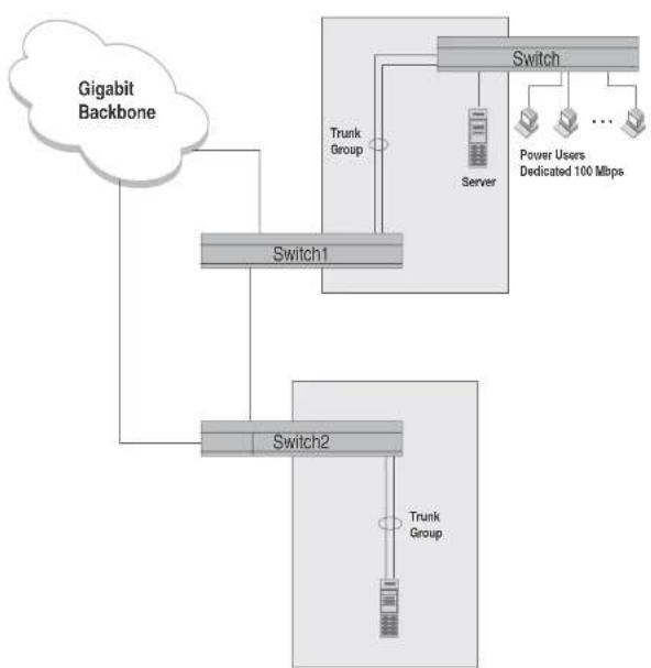
flowchart
graph TD
    A["Gigabit Backbone"] --> B["Switch1"]
    B --> C["Switch2"]
    C --> D["Trunk Group"]
    D --> E["Switch"]
    E --> F["Server"]
    F --> G["Power Users Dedicated 100 Mbps"]
    B --> H["Trunk Group"]
    H --> I["Switch1"]
    I --> J["Switch2"]
FIGURE 79 Trunk group between a server and a compact Layer 2 Switch or Layer 3 Switch
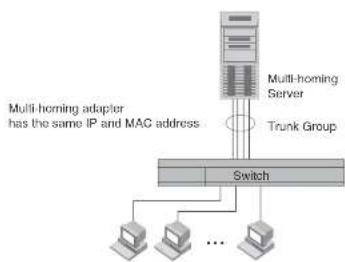
flowchart
graph TD
    A["Multi-homing Server"] --> B["Switch"]
    C["Multi-homing adapter has the same IP and MAC address"] --> B
    D["Trunk Group"] --> B
    E["Computer 1"] --> B
    F["Computer 2"] --> B
    G["Computer 3"] --> B
    H["..."] --> B
Trunk group rules
Table lists the maximum number of trunk groups you can configure on a Dell PowerConnect device and the valid number of ports in a trunk group. The table applies to static and LACP trunk ports.
TABLE 71 Trunk group support
| Model Maximum number of Gbps trunk groups | Valid number of ports In a group | |
| PowerConnect | 32 2, 3, 4, 5, 6, 7, or 8 | |
| B FCX624 | ||
| PowerConnect | ||
| B FCX648 | ||
- In a hardware configuration with a IPv4 and IPv6 interface modules or management modules with user ports, legacy ports and 48 Gbps copper ports cannot be members of the same trunk group.
• statically configured port speed and duplex
- QoS priority
To change port parameters, you must change them on the primary port. The software automatically applies the changes to the other ports in the trunk group.
Configuration notes for Dell PowerConnect devices in an IronStack
In a Dell IronStack system, a trunk group may have port members distributed across multiple stack units. Both static and dynamic trunking are supported.
NOTE
Cascaded trunks between stack units are not currently supported.
To configure trunk groups for PowerConnect devices in an IronStack, use the CLI syntax in "CLI syntax for configuring consecutive ports in a trunk group" on page 400.
These notes apply to FastIron Stackable devices that are part of an IronStack.
- If a stack unit fails, or is removed from the stack its static trunk configuration becomes a reserved configuration on the Active Controller. Any remaining ports of the static trunk in the IronStack continue to function.
- When a new stack unit is added to an IronStack, the new unit receives running configuration and trunk-related information, including a list of ports that are up and are members of a trunk, from the Active Controller.
- Before merging two IronStacks, make sure that there are no static trunks configured between them. This can result in self-looped ports.
- When an IronStack with static trunks partitions into multiple IronStacks, loops and forwarding errors may occur. In these cases, user intervention is required to remove the loops.
• 10 Gbps links support up to eight ports in a trunk for stackable units.
Trunk group configuration examples
Figure 80 shows some examples of valid 2-port trunk group links between devices. The trunk
Trunk group overview
FIGURE 80 Examples of 2-port and 3-port trunk groups
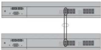
text_image
Diagram showing two labeled electronic device ports with connection points and connectors, likely from an Ethernet interface.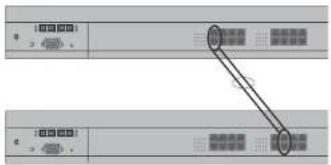
text_image
Diagram showing two labeled panels with arrows pointing to a central diagram, likely illustrating a process or flow between two components.
text_image
Diagram of a rack-mounted server rack with labeled ports and a highlighted connection point, showing port numbers and status indicators.FIGURE 81 Two IronStacks connected by multi-slot trunk groups

flowchart
graph TD
    A["Server Rack"] --> B["Port 1"]
    A --> C["Port 2"]
    A --> D["Port 3"]
    A --> E["Port 4"]
    A --> F["Port 5"]
    B --> G["Terminal Node"]
    C --> H["Terminal Node"]
    D --> I["Terminal Node"]
    E --> J["Terminal Node"]
    F --> K["Terminal Node"]
    G --> L["Terminal Node"]
    H --> M["Terminal Node"]
    I --> N["Terminal Node"]
    J --> O["Terminal Node"]
    K --> P["Terminal Node"]
Support for flexible trunk group membership
PowerConnect devices support flexible trunk group membership, which eliminates the requirement for port membership to be consecutive, and allows the trunking of ports on non-consecutive interfaces. For example, you can configure ports e 2/4, 2/6, and 2/7 (excluding e 2/5) together on a module as a trunk group. This feature is supported on static and LACP trunk ports, as well as GbE and 10-GbE ports. Flexible trunk ports follow the same rules as listed in "Trunk group rules" on page 395.
NOTE
For PowerConnect B-Series FCXPowerConnect B-Series FCXdevices only, this feature is supported from Web Management, but not from SNMP. For all other PowerConnect devices, this feature is not supported from SNMP or Web management.
For configuration details, see "CLI syntax for configuring non-consecutive ports in a trunk group" on page 401.
Trunk group load sharing
Dell PowerConnect devices load-share across the ports in the trunk group. The method used for the load-sharing depends on the device type and traffic type (if over 0 or less than).
Load sharing for unknown unicast, multicast, and broadcast traffic
Dell PowerConnect devices load balance unknown unicast, multicast, and broadcast traffic based on the source port and VLAN ID and not on any source or destination information in the packet.
For example, when the switch receives unknown unicast, multicast, and broadcast packets, and the packets are from the same source port, the packets are forwarded to the same port of the trunk group. Conversely, when the switch receives unknown unicast, multicast, and broadcast packets, and the packets are from different source ports, the packets are load-balanced across all the ports of the trunk group.
Note that this does not apply to known unicast traffic, which is always load balanced across all the ports of a trunk group based on the traffic's Layer 2 and Layer 3 source and destination parameters.
How trunk load sharing works
The load balancing method for bridged traffic varies depending on the traffic type. Load balancing for routed traffic is always based on the source and destination IP addresses and protocol field (not applicable for FastIron Stackable devices).
NOTE
Table 72 do not include unknown unicast, multicast, and broadcast traffic. Refer to "Load sharing for unknown unicast, multicast, and broadcast traffic".
Table 72 describes how the FastIron Stackable devices load balance traffic.
TABLE 72 Trunk group load sharing on FastIron Stackable devices
Traffic type Load balancing method
L2 Bridged Non-IP Source MAC, Destination MAC
L2 Bridged IPv4 TCP/UDP Source IP, Destination IP, Source TCP/UDP Port, Destination TCP/UDP Port
12 Bridged IPv4 Non-TCP/UDP Source IP Destination IP
- IPv6 TCP/UDP: Source IP, Destination IP, Flow Label, Source TCP/UDP Port, Destination TCP/UDP Port, Source MAC, Destination MAC
- IPv6 Non-TCP/UDP: Source IP, Destination IP, Flow Label, Source MAC, Destination MAC
Syntax: [no] trunk hash-options include-layer2
Configuring a trunk group
Follow the steps given below to configure a trunk group.
- Disconnect the cables from those ports on both systems that will be connected by the trunk group. Do not configure the trunk groups with the cables connected.
NOTE
If you connect the cables before configuring the trunk groups and then rebooting, the traffic on the ports can create a spanning tree loop.
- Configure the trunk group on one of the two Layer 2 Switches or Layer 3 Switches involved in the configuration.
NOTE
Downtime is incurred when adding a new port to a trunk group. It is suggested that you schedule the addition of ports to a trunk group to minimize downtime and its impact to the production network.
- Save the configuration changes to the startup-config file.
- Dynamically place the new trunk configuration into effect by entering the trunk deploy command at the global CONFIG level of the CLI.
- If the device at the other end of the trunk group is another Layer 2 Switch or Layer 3 Switch, repeat Steps 2 - 4 for the other device.
- When the trunk groups on both devices are operational, reconnect the cables to those ports that are now configured as trunk groups, starting with the first port (lead port) of each trunk
Syntax: trunk deploy
Each ethernet parameter introduces a port group.
The
Specify the
• PowerConnect B-Series FCX stackable switches -
You can list all of the ports individually, use the keyword to to specify ranges of ports, or a combination of both.
CLI syntax for configuring non-consecutive ports in a trunk group
This section describes the CLI syntax for configuring non-consecutive ports in a trunk group. Configuration examples are shown in later sections of this chapter.
To configure a 4-port trunk with non-consecutive ports on a PowerConnect Chassis device, enter a command such as the following.
PowerConnect(config)#l.runk elhe 1/7 elhe 1/9 elhe 1/11 elhe 1/21
This creates a 4-port trunk group with the following members.
1/7, 1/9, 1/11, 1/21
To configure a 4-port trunk with non-consecutive ports on a FastIron Stackable device, enter a command similar to the following.
PowerConnect(config)#L-runk elhe 1/1/7 elhe 1/1/9 elhe 1/1/11 elhe 1/1/21
This creates a 4-port trunk group with the following members.
1/1/7, 1/1/9, 1/1/11, 1/1/21
Syntax: [no] trunk ethernet
The
NOTE
The text shown in italics in the CLI example below shows messages echoed to the screen in answer to the CLI commands entered.
PowerConnect(config)#trunk e 1/5 to 1/8
Trunk will be created in next trunk deploy
PowerConnect(config)#WRITE memory
PowerConnect(config)#trunk deploy
To configure the trunk group link between device2 and the server, enter the following commands
PowerConnect(config)#trunk e 1/2 to 1/4
Trunk will be created in next trunk deploy
PowerConnect(config)#write memory
PowerConnect(config)#trunk deploy
You then configure the trunk group on the Device.
PowerConnect{config}#trunk ethernet 17 to 18
Trunk will be created in next trunk deploy
PowerConnect(config)#write memory
PowerConnect (config) #Ltrunk deploy
NOTE
The trunk deploy command dynamically places trunk configuration changes into effect, without a software reload.
Example 2: Configuring a trunk group that spans
two Gbps Ethernet modules in a chassis device
This section shows how to configure a trunk group that spans two modules in a Chassis device.
Multi-slot trunk groups are supported on 1-GbE ports, 10-GbE ports, as well as on static and LACP trunk ports. For multi-slot trunk group rules, refer to Table 74 on page 414.
To configure a trunk group consisting of two groups of ports, 1/1 - 1/2 on module 1 and 4/5 - 4/6 on module 4, enter the following commands.
Example 3: Configuring a multi-slot trunk group with one port per module
You can select one port per module in a multi-slot trunk group. This feature is supported on GbE and 10-GbE ports, as well as on static and LACP trunk ports. For multi-slot trunk group rules, refer to Table 74 on page 414.
To configure a two-port multi-slot trunk group consisting of ports 1/1 on module 1 and 2/1 on module 2, enter the following commands.
PowerConnect{config}#trunk ethernet 1/1 to 1/1 ethernet 2/1 to 2/1
Trunk will be created in next trunk deploy
PowerConnect{config}#write memory
PowerConnect{config}#trunk deploy
NOTE
The trunk deploy command dynamically places trunk configuration changes into effect, without a software reload.
NOTE
If you disable a module that is part of a multi-slot trunk group, the corresponding trunk ports will remain up and running. However, when you re-enable the module, all of the trunk ports will go down then come back up. In other words, trunk ports are re-deployed when a module is re-enabled.
Example 4: Configuring a trunk group of 10 Gbps Ethernet ports
You can configure 10 Gbps Ethernet ports together in a trunk group.
To configure a trunk group containing two 10 Gbps Ethernet ports, enter commands such as the following.
PowerConnect(config)#trunk ethernet 1/1 to 2/1
PowerConnect(config-trunk-1/1-2/1)# write memory
PowerConnect(config-trunk-1/1-2/1)# exit
STK1(config)#trunk ethe 1/1/1 ethe 2/1/4 ethe 3/1/7 ethe 4/1/2 ethe 5/1/5 ethe 6/1/7 ethe 7/1/2 ethe 7/1/5
Trunk will be created in next trunk deploy.
STK1(config)#trunk deploy
STK1 (config) ↓show trunk
Configured trunks:
Trunk ID: 1
Hw Trunk ID: 1
Ports_Configured: 8
Primary Port Monitored: Jointly
Ports 1/2/1 2/1/4 3/1/7 4/1/2 5/1/5 6/1/7 7/1/2 7/2/5
Port Names none none none none none none none none
Port_Status enable enable enable enable enable enable enable
Monitor off off off off off off off off
Rx Mirr Port N/A N/A N/A N/A N/A N/A N/A
Tx Mirr Port N/A N/A N/A N/A N/A N/A N/A N/A
Monitor Dir N/A N/A N/A N/A N/A N/A N/A N/A
Operational trunks:
Trunk ID: 1
Hw Trunk ID: 1
Duplex: None
Speed: None
Tag: Yes
Priority: level0
Active Ports: 0
Ports 1/1/1 2/1/4 3/1/7 4/1/2 5/1/5 6/1/7 7/1/2 7/1/5
Link_Status active active active active active active active active active
port_state Forward Forward Forward Forward Forward Forward Forward
- Setting the sFlow sampling rate on an individual port in a trunk
NOTE
Depending on the operational state of LACP-enabled ports, at any time, these ports may join a trunk group, change trunk group membership, exit a trunk group, or possibly never join a trunk group. Therefore, before configuring trunking options on LACP-enabled ports (e.g., naming the port, disabling the port, etc.), verify the actual trunk group port membership using the show trunk command. To view the status of LACP, use the show link-aggregate command.
Naming a trunk port
This feature is supported on individual ports of a static trunk group.
To name an individual port in a trunk group, enter a command such as the following at the trunk group configuration level.
PowerConnect(config)#trunk e 4/1 to 4/4
PowerConnect(config-trunk-4/1-4/4)#port-name customer1 ethernet 4/2
This command assigns the name "customer1" to port 4/2 in the trunk group consisting of ports 4/1 - 4/4.
Syntax: [no] port-name
The
The
Specify the
• PowerConnect B-Series FCX stackable switches -
Disabling or re-enabling a trunk port
This feature is supported on individual ports of a static trunk group.
You can disable or re-enable individual ports in a trunk group. To disable an individual port in a trunk group, enter commands such as the following at the trunk group configuration level.
NOTE
If you enter no config-trunk-ind, all port configuration commands are removed from the individual ports and the configuration of the primary port is applied to all the ports. Also, once you enter the no config-trunk-ind command, the enable, disable, and monitor commands are valid only on the primary port and apply to the entire trunk group.
The disable command disables the port. The states of other ports in the trunk group are not affected.
If you have configured a name for the trunk port, you can specify the port name, as shown in the following example.
PowerConnect(config-trunk-4/1-4/4)#config-trunk-ind PowerConnect(config-trunk-4/1-4/4)#disable customer1
Syntax: disable
To enable an individual port in a trunk group, enter commands such as the following at the trunk group configuration level.
PowerConnect(config-trunk-4/1-4/1)#config-trunk-ind PowerConnect(config-trunk-4/1-4/4)#enable ethernet 4/2
Syntax: enable ethernet ]
Specify the
• PowerConnect B-Series FCX stackable switches -
Syntax: enable
Disabling or re-enabling a range or list of trunk ports
To disable a range of ports in a trunk group, enter commands such as the following.
PowerConnect(config)#trunk ethernet 2/1 to 2/4 PowerConnect(config-trunk-2/1-2/4)#config-trunk-ind PowerConnect(config-trunk-2/1-2/4)#disable ethernet 2/3 to 2/4
This command disables ports 2/3 - 2/4 in trunk group 2/1 - 2/4.
To disable a list of ports, enter a command such as the following:
The to keyword indicates that you are specifying a range. Specify the lower port number in the range first, then to, then the higher port number in the range.
Deleting a static trunk group
Use the command in this section to delete a static trunk group.
NOTE
To delete an LACP trunk group, use the CLI command no link-aggregate active | passive.
To delete a trunk group, use no in front of the command you used to create the trunk group. For example, to remove one of the trunk groups configured in the examples above, enter the following command.
PowerConnect(config)#no trunk ethernet 1/1 to 1/2 ethernet 3/3 to 3/4
Syntax: no trunk ethernet
The
• PowerConnect B-Series FCX stackable switches -
You can enter the ethernet
The to keyword indicates that you are specifying a range of ports. Specify the lower port number in the range first, then to, then the higher port number in the range.
Specifying the minimum number of ports in a static trunk group
You can configure Dell PowerConnect devices to disable all of the ports in a trunk group when the number of active member ports drops below a specified threshold value. For example, if a trunk group has 4 ports, and the threshold for the trunk group is 3, then the trunk group is disabled if the number of available ports in the trunk group drops below 3. If the trunk group is disabled, then traffic is forwarded over a different link or trunk group.
For example, the following commands establish a trunk group consisting of 4 ports, then establish a threshold for this trunk group of three ports.
- The disable module command can be used to disable the ports on a module. However, on 10 Gbps modules, the disable module command does not cause the remote connection to be dropped. If a trunk group consists of 10 Gbps ports, and you use the disable module command to disable ports in the trunk group, which then causes the number of active ports in the trunk group to drop below the threshold value, the trunk group is not disabled.
- If you establish a threshold for a trunk used in conjunction with Metro Ring Protocol (MRP) on 10 Gbps interfaces, then you must also enable Link Fault Signaling (LFS).
- If you specify a threshold for a trunk group, the other end of the trunk group must also have the same threshold configuration.
Monitoring a trunk port
You can monitor the traffic on an individual port of a static trunk group. For configuration details, refer to "Monitoring an individual trunk port" on page 636.
Configuring outbound rate shaping for a trunk port
You can configure the maximum rate at which outbound traffic is sent out on a static trunk port. For configuration details, refer to "Configuring outbound rate shaping for a trunk port" on page 647.
Enabling sFlow forwarding on a trunk port
You can enable sFlow forwarding on individual ports of a static trunk group. For configuration details, refer to "Enabling sFlow forwarding on individual trunk ports" on page 1435.
Setting the sFlow sampling rate on a trunk port
You can configure an individual trunk port to use a different sampling rate than the global default sampling rate. This feature is supported on static trunk ports. For configuration details, refer to "Changing the sampling rate for a trunk port" on page 1434.
Displaying trunk group configuration information
NOTE
The show trunk command does not display any form of trunk when links are up.
Table 73 describes the information displayed by the show trunk command.
TABLE 73 CLI trunk group information
| This field... Displays... |
| Trunk ID The trunk group number. The software numbers the groups in the display to make the display easy to use. |
| HW Trunk ID The trunk ID. |
Duplex The mode of the port, which can be one of the following:
- None – The link on the primary trunk port is down.
• Full – The primary port is running in full-duplex.
- Half - The primary port is running in half-duplex.
NOTE: This field and the following fields apply only to operational trunk groups.
Speed The speed set for the port. The value can be one of the following:
- None - The link on the primary trunk port is down.
• 10 - The port speed is 10 Mbps.
• 100 - The port speed is 100 Mbps.
- IG - The port speed is 1000 Mbps.
Tag Indicates whether the ports have 802.1Q VLAN tagging. The value can be Yes or No.
Priority Indicates the Quality of Service (QoS) priority of the ports. The priority can be a value
from 0 - 7
Active Ports The number of ports in the trunk group that are currently active.
Ports The ports in the trunk group.
Link_Status The link status or each port in the trunk group.
LACP_Status For more information about this feature, refer to the section "Displaying and
determining the status of aggregate links" on page 421:
- Ready - The port is functioning normally in the trunk group and is able to transmit and receive LACP packets.
• Expired - The time has expired (as determined by timeout values) and the port has
PowerConnect#show mac
Total active entries from all ports - 1
MAC-Address Part Type Index
0007.c910.c201 1/1/7*1/1/21 Dynamic 2920
For a trunk group with members 1/1/7 to 1/1/9, the output from the show mac command resembles the following.
PowerConnect+show, zac
Total active entries from all ports - 1
MAC-Address Part Type Index
0007.e910.c201 1/1/7-1/1/9 Dynamic 2920
Dynamic link aggregation
Dell software supports the IEEE 802.3ad standard for link aggregation. This standard describes the Link Aggregation Control Protocol (LACP), a mechanism for allowing ports on both sides of a redundant link to form a trunk link (aggregate link), without the need for manual configuration of the ports into trunk groups.
When you enable link aggregation on a group of Dell PowerConnect ports, the Dell PowerConnect ports can negotiate with the ports at the remote ends of the links to establish trunk groups.
The link aggregation feature automates trunk configuration but can coexist with the Dell trunk group feature. Link aggregation parameters do not interfere with trunk group parameters.
NOTE
Use the link aggregation feature only if the device at the other end of the link you want to aggregate also supports IEEE 802.3ad link aggregation. Otherwise, you need to manually configure the trunk links.
Link aggregation support is disabled by default. You can enable the feature on an individual port basis, in active or passive mode:
• Active mode – When you enable a port for active link aggregation, the Dell PowerConnect port can exchange standard IACP Protocol Data Unit (IACPDU) messages to negotiate trunk group
- With LACP trunk configurations, the LACP system id is the MAC address of the Active Controller. If the LACP system id changes, the entire trunk flaps and an STP re-convergence occurs.
- Link aggregation can be used to form multi-slot aggregate links on stack units, but the link aggregation keys must match for the port groups on each stack unit. For example, to configure an aggregate link containing ports 1/1/1 through 1/1/4, and 3/1/5 through 3/1/8, you must change the link aggregation key on one or both port groups so that the key is the same for all 8 ports. See the following example.
IronStack LACP trunk group configuration example
To configure a trunk group consisting of two groups of two ports each on an IronStack, enter commands similar to the following.
PowerConnect(config)#interface ethernet 1/1/1 to 1/1/4
PowerConnect(config-mif-1/1-1/1-1/4)†link-aggregate off
PowerConnect(config-mif-1/1/1-1/1/4)‡link-aggregate configure key 10000
PowerConnect(config-mif-1/1-1/1-1/4)‡link-aggregate active
PowerConnect(config-mif 1/1/1 1/1/4)‡interface ethernet 3/1/5 to 3/1/8
PowerConnect(config-mif-3/1/5-3/1/8)‡link-aggregate off
PowerConnect(config-mif-3/1/5-3/1/8)‡link-aggregate configure key 10000
PowerConnect(config-mif 3/1/5-3/1/8)‡link-aggregate active
This command sequence changes the key for ports 1/1/1-1/1/4 and 3/1/5-3/1/8 to 10000. Since all ports in an aggregate link must have the same key, this example forms a multi-slot aggregate link for ports 1/1/1-1/1/4 and 3/1/5-3/1/8.
Examples of valid LACP trunk groups
Dell PowerConnect ports follow the same configuration rules for dynamically created aggregate links as they do for statically configured trunk groups. Refer to "Trunk group rules" on page 395 and "Trunk group load sharing" on page 398.
Figure 82 on page 412 shows some examples of valid aggregate links.
FIGURE 82 Examples of valid aggregate links
Ports enabled for link
aggregation follows the same rules
as ports configured for trunk groupe

flowchart
graph TD
    A["Port1"] --> B["○"]
    C["Port2"] --> B
    D["Port3"] --> B
    E["Port4"] --> B
    F["Port5"] --> B
    G["Port6"] --> H["○"]
    I["Port7"] --> H
    J["Port8"] --> H
    B --> K[" "]
    B --> L[" "]
    B --> M[" "]
    B --> N[" "]
    B --> O[" "]
    B --> P[" "]
    B --> Q[" "]
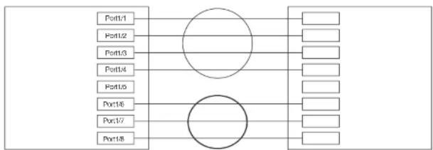
flowchart
graph TD
    A["Port1/1"] --> B(( ))
    C["Port1/2"] --> B
    D["Port1/3"] --> B
    E["Port1/4"] --> B
    F["Port1/5"] --> B
    G["Port1/6"] --> H(( ))
    I["Port1/7"] --> H
    J["Port1/8"] --> H
    B --> K["Output"]
    H --> K
    style B fill:#fff,stroke:#000
    style H fill:#fff,stroke:#000

flowchart
graph LR
    A["Port1"] --> C(( ))
    B["Port2"] --> C
    D["Port3"] --> C
    E["Port4"] --> C
    C --> F["Output Module"]
    style C fill:#f9f,stroke:#333,stroke-width:2px
FastIron Stackable devices
The following notes and feature limitations apply to the PowerConnect B-Series FCX devices.
- The dynamic link aggregation (802.3ad) implementation allows any number of ports up to eight to be aggregated into a link.
- The default key assigned to an aggregate link is based on the port type (1 Gbps port or 10 Gbps port). The device assigns different keys to 10 Gbps ports than on 1 Gbps ports so that ports with different physical capabilities will not be able to form a trunk.
NOTE
The trunks that will be formed by link aggregation will strictly adhere to the static trunking rules on the Stackable devices. Be careful in selecting keys if you are manually configuring link aggregation keys. Make sure that the possible trunks that you expect to be formed conform to the static trunking rules.
- When you enable link aggregation (LACP) on a group of Dell PowerConnect ports, you must also assign a unique key (other than the default key) to all of the ports in the aggregate link.
• 10 Gbps links only support two port trunks.
FastIron Stackable devices in an IronStack
- If a stack unit fails, or is removed from the stack, its LACP configuration becomes a reserved configuration on the Active Controller. Any remaining ports of the dynamic trunk in the IronStack continue to function.
- Merging two IronStacks with a dynamic trunk configured between them results in self-looped ports, which are detected and corrected by the Spanning Tree Protocol (STP). LACP configuration on the winning Active Controller is not affected by the LACP configuration on the losing Active Controller is lost after the merge.
- When an IronStack with dynamic trunks partitions into multiple IronStacks, the protocol will take care of splitting the dynamic trunk in the partner. No user intervention is required.
Adaptation to trunk disappearance
Figure 83 shows an example of 2-port groups in a range of four ports on which link aggregation is enabled. Based on the states of the ports, some or all of them will be eligible to be used in an aggregate link.
FIGURE 83 Two-port groups used to determine aggregation eligibility

flowchart
graph TD
    A["Group 1"] --> B["Port1/1"]
    A --> C["Port1/2"]
    D["Group 2"] --> E["Port1/3"]
    D --> F["Port1/4"]
Table 74 shows examples of the ports from Figure 83 that will be eligible for an aggregate link based on individual port states.
TABLE 74 Port eligibility for link aggregation
| Port group 1 Port group 2 Trunk eligibility | |||||||||
| 1/1 1/2 1/3 1/4 | |||||||||
| L | i | n | k | S | t | a | t | e | |
| 1/1 - 1/4 | |||||||||
| Up Up Up Down 4-port | 1/1 - 1/4 | ||||||||
| Up Down Up Down 4-port | 1/1 - 1/4 | ||||||||
NOTE
Configuration commands for link aggregation differ depending on whether you are using the default link aggregation key automatically assigned by the software, or if you are assigning a different, unique key. Follow the commands below, according to the type of key you are using. For more information about keys, refer to "Key" on page 417.
Using the default key assigned by the software
PowerConnect (config) 4interface ethernet 1/1
PowerConnect(config-if-e1000-1/1)†link-aggregate active
PowerConnect{config}#interface ethernet 1/2
PowerConnect(config-if-ol000-1/2)↑link-aggregate active
The commands in this example enable the active mode of link aggregation on ports 1/1 and 1/2. The ports can send and receive LACPDU messages. Note that these ports will use the default key, since one has not been explicitly configured.
NOTE
In conformance with the 802.3ad specification, the default key assigned to an aggregate link is based on the port type (1 Gbps port or 10 Gbps port). The Dell PowerConnect device assigns different keys to 10 Gbps ports than 1 Gbps ports, so that ports with different physical capabilities will not be able to form a trunk.
Assigning a unique key
PowerConnect {config} #interface ethernet 1/1
PowerConnect(config-if-e1000-1/1)↓link-aggregate configure key 10000
PowerConnect(config-if-ol000-l/1)#link-aggregate active
PowerConnect(config)#interface ethernet 1/2
PowerConnect(config-if-e1000-1/2)↓link-aggregate configure key 10000
PowerConnect(config-if-e1000-1/2)#link-aggregate active
The commands in this example assign the key 10000 and enable the active mode of link aggregation on ports 1/1 and 1/2. The ports can send and receive LACPDU messages.
NOTE
As shown in this example, when configuring a key, it is pertinent that you assign the key prior to
NOTE
For more information about keys, including details about the syntax shown above, refer to "Key" on page 417.
How changing the VLAN membership of a port affects trunk groups and dynamic keys
When you change a port VLAN membership and the port is currently a member of a trunk group, the following changes occur to the trunk group:
- The Dell PowerConnect device tears down the existing trunk group.
- All ports in the trunk group get a new key.
• The new key group aggregates into a new trunk group.
When you change a port VLAN membership, and the port is not a member of a trunk group, the following changes occur:
• The port gets a new key depending on changes to the port VLAN tag type, as follows:
- Tagged to Tagged VLAN – The primary port of the trunk group gets a new key.
- Tagged to Untagged VLAN -The port gets the default key for untagged ports.
- Untagged to Tagged VLAN – If the Dell PowerConnect device finds a port with matching port properties, the port gets that port key. If it does not find one, the port gets a new key.
- Untagged to Untagged VLAN – The port gets a new key depending on whether it is in the default VLAN or not. If there is a trunk group associated with the key, it is not affected.
- All other ports keep their existing key.
- The new key groups try to aggregate into trunk groups.
Additional trunking options for LACP trunk ports
Additional trunking options are supported on individual ports that are part of an 802.3ad aggregate link. Refer to "Additional trunking options" on page 404.
NOTE
If you are connecting the Dell PowerConnect device to another vendor device and the link aggregation feature is not working, set the system priority on the Dell PowerConnect device to a lower priority (a higher priority value). In some cases, this change allows the link aggregation feature to operate successfully between the two devices.
Port priority
The port priority parameter determines the active and standby links. When a group of ports is negotiating with a group of ports on another device to establish a trunk group, the Dell PowerConnect port with the highest priority becomes the default active port. The other ports (with lower priorities) become standby ports in the trunk group. You can specify a priority from 0 - 65535. A higher value indicates a lower priority. The default is 1.
NOTE
This parameter is not supported in the current software release. The primary port in the port group becomes the default active port. The primary port is the lowest-numbered port in a valid trunk-port group.
Timeout
You can specify a timeout mode, which determines how fast ports are removed from a trunk. You can specify a short timeout mode.
Key
Every port that is 802.3ad-enabled has a key. The key identifies the group of potential trunk ports to which the port belongs. Ports with the same key are called a key group and are eligible to be in the same trunk group.
When you enable link-aggregation on an untagged port, the software assigns a default key to the port. For tagged ports, you must manually configure link-aggregation keys. Refer to "Configuring keys for ports with link aggregation enabled" on page 420.
FIGURE 84 Ports with the same key in different aggregate links
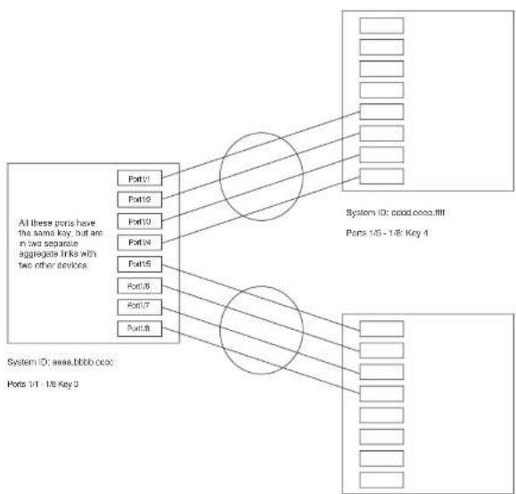
flowchart
graph TD
    A["All these ports have the same key, but are in two separate aggregate links with two other devices."] --> B["Port1"]
    A --> C["Port2"]
    A --> D["Port3"]
    A --> E["Port4"]
    A --> F["Port5"]
    A --> G["Port6"]
    A --> H["Port7"]
    A --> I["Port8"]
    B --> J["System ID: cood.coco.iii"]
    C --> J
    D --> J
    E --> J
    F --> J
    G --> J
    H --> J
    I --> J
    J --> K["Ports 15 - 18 Key 4"]
System ID: 1111.2222.3333
Ports 1/5 - 1/8: Key 69
Notice that the keys between one device and another do not need to match. The only requirement
FIGURE 85 Multi-slot aggregate link

flowchart
graph LR
    A["Port1"] --> B["Port2"]
    B --> C["Port3"]
    C --> D["Port4"]
    E["Port5"] --> F["Port6"]
    G["Port7"] --> H["Port8"]
    I["Port9"] --> J["Port10"]
    K["Port11"] --> L["Port12"]
    M["Port13"] --> N["Port14"]
    O["Port15"] --> P["Port16"]
    Q["Port17"] --> R["Port18"]
    S["Port19"] --> T["Port20"]
    U["Port21"] --> V["Port22"]
    W["Port23"] --> X["Port24"]
    Y["Port25"] --> Z["Port26"]
    AA["Port27"] --> AB["Port28"]
    AC["Port29"] --> AD["Port2A"]
    AE["Port30"] --> AF["Port3B"]
    AG["Port31"] --> AH["Port3C"]
    AI["Port32"] --> AJ["Port3D"]
    AK["Port33"] --> AL["Port3E"]
System ID: aaaa.bbbb.cccc
Porta 1/1 - 1/4: Key 0
By default, the device ports are divided into 4-port groups. The software dynamically assigns a unique key to each 4-port group. If you need to divide a 4-port group into two 2-port groups, change the key in one of the groups so that the two 2-port groups have different keys. For example, if you plan to use ports 1/1 and 1/2 in VLAN 1, and ports 1/3 and 1/4 in VLAN 2, change the key for ports 1/3 and 1/4.
Viewing keys for tagged ports
To display link aggregation information, including the key for a specific port, enter a command such as the following at any level of the CLI.
PowerConnect#show link-aggregate ethernet 1/1
System ID: 00e0.52a9.bb00
Part [Sys P] [Part P] [Key] [Act] [Tic] [Agu] [Syn] [Col] [Dis] [Def] [Exp]
1/1 0 0 0 No L No No No No No
The command in this example shows the key and other link aggregation information for port 1/1.
To display link addrsation information, including the key for all parts on which link addrsation is
PowerConnect#show link-aggregate
System ID: 0004.8055.b200
Long timeout: 90, default: 90
Short timeout: 3, default: 3
| Port | [Sys P] | [Port P] | [ Key ] | [Act] | [Tio] | [Agg] | [Syn] | [Col] | [Dis] | [Def] | [Exp] | [Opo] |
| 1/1 | 1 | 1 | 10000 | Yes | S | Aqq | Syn | Col | Dis | Def | No | Dwn |
| 1/2 | 1 | 1 | 10000 | Yes | S | Agg | Syn | Col | Dis | Def | No | Dwn |
| 2/1 | 1 | 1 | 10000 | Yes | S | Aqq | Syn | Col | Dis | Def | No | Dwn |
| 2/2 | 1 | 1 | 10000 | Yes | S | Aqq | Syn | Col | Dis | Def | No | Dwn |
| 4/1 | 1 | 1 | 450 | Yes | S | Agg | Syn | Col | Dis | Def | No | Dwn |
| 4/2 | 1 | 1 | 450 | Yes | S | Aqq | Syn | Col | Dis | Def | No | Dwn |
| 4/3 | 1 | 1 | 450 | Yes | S | Agg | Syn | Col | Dis | Def | No | Dwn |
| 4/4 | 1 | 1 | 450 | Yes | S | Agg | Syn | Col | Dis | Def | No | Dwn |
| 4/17 | 1 | 1 | 461 | Yes | S | Aqq | Syn | Col | Dis | Def | No | Ope |
| 4/18 | 1 | 1 | 461 | Yes | S | Agg | Syn | Col | Dis | Def | No | Ope |
| 4/19 | 1 | 1 | 461 | Yes | S | Aqq | Syn | Col | Dis | Def | No | Ope |
| 4/20 | 1 | 1 | 461 | Yes | S | Agg | Syn | Col | Dis | Def | No | Ope |
Syntax: show link-aggregate [ethernet
Specify the
• PowerConnect B-Series FCX stackable switches -
Configuring link aggregation parameters
You can configure one or more parameters on the same command line, and in any order.
NOTE
For key configuration only, configuration commands differ depending on whether or not link aggregation is enabled on the ports. Follow the appropriate set of commands below, according to your system configuration.
Configuring a port group key if link aggregation is disabled
Use this command sequence to change the key for ports that do not have link aggregation enabled, and for all other link aggregation parameters (i.e., system priority, port priority).
PowerConnect(config-mif-1/1-1/4)↑interface ethernet 3/5 to 3/8 PowerConnect(config-mif-3/5-3/8)↑link-aggregate off PowerConnect(config-mif-3/5-3/8)↑link-aggregate configure key 10000 PowerConnect(config-mif-3/5-3/8)↑link-aggregate active
These commands change the key for ports 1/1 - 1/4 and 3/5 - 3/8 to 10000. Since all ports in an aggregate link must have the same key, the command in this example enables ports 1/1 - 1/4 and 3/5 - 3/8 to form a multi-slot aggregate link.
Syntax: [no] link-aggregate configure [system-priority
The system-priority
The port-priority
The key
Configuring port timeout
You can control the time it takes to remove ports from a trunk with link aggregation enabled by configuring the link aggregated port with a "short" timeout mode. Once a port is configured with a timeout mode, it will remain in that timeout mode whether it is up or down or whether or not it is part of a trunk.
All ports in a trunk should have the same timeout mode, which is checked when link aggregation is enabled on ports.
To configure a port with a short timeout mode, enter a command such as the following.
PowerConnect(config)#interface ethernet8/1 PowerConnect(config-if-e1000-8/1)#link-aggregate configure timesput short
Syntax: [no] link-aggregate configure timeout [short]
Events that affect the status of ports in an aggregate link
Dell PowerConnect devices can block traffic on a port or shut down a port that is part of a trunk group or aggregate link, when a port joins a trunk group and the port on the other end of the link shuts down or stops transmitting LACP packets. Depending on the timeout value set on the port, the link aggregation information expires. If this occurs, the Dell PowerConnect device shuts down the port and notifies all the upper layer protocols that the port is down.
Dell PowerConnect devices can also block traffic on a port that is initially configured with link aggregation. The port is blocked until it joins a trunk group. In this case, traffic is blocked, but the port is still operational.
A port remains blocked until one of the following events occurs:
- Both ports in the aggregate link have the same key
• LACP brings the port back up
• The port joins a trunk group
Displaying link aggregation and port status information
Use the show link-aggregate command to determine the operational status of ports associated with aggregate links.
To display the link aggregation information for a specific port, enter a command such as the following at any level of the CLI.
| PowerConnect+show link-aggregate ethernet 1/1 | ||||||||||||
| System ID: 00e0.52a9.bb00 | ||||||||||||
| Port | [Sys P] | [Port P] | | Key | | [Act] | [Tio] | [Agg] | [Syn] | [Col] | [Dis] | [Def] | [Exp] | [Ope] |
| 1/1 | 0 | 0 | 0 | No | L | No | No | No | No | No | No | Ope |
The command in this example shows the link aggregation information for port 1/1.
To display the link aggregation information for all ports on which link aggregation is enabled, enter the following command at any level of the CLI.
NOTE
Ports that are configured as part of an aggregate link must also have the same key. For more information about assigning keys, refer to the section "Link aggregation parameters" on page 416.
The show link-aggregate command shows the following information.
TABLE 75 CLI display of link aggregation information
| This field... Displays... |
| System ID Lists the base MAC address of the device. This is also the MAC address of port 1 (or 1/1). |
| Port Lists the port number. |
| Sys P Lists the system priority configured for this port. |
| Port P Lists the port link aggregation priority. |
| Key Lists the link aggregation key.This column displays "singleton" if the port is configured with a Single instance of LACP. (Refer to "Configuring single link LACP" on page 425 for more details. |
Act Indicates the link aggregation mode, which can be one of the following:
- No - The mode is passive or link aggregation is disabled (off) on the port.
If link aggregation is enabled (and the mode is passive), the port can send and receive LACPDU messages to participate in negotiation of an aggregate link initiated by another port, but cannot search for a link aggregation port or initiate negotiation of an aggregate link. - Yes – The mode is active. The port can send and receive LACPDU messages.
Tio Indicates the timeout value of the port. The timeout value can be one of the following:
- L – Long. The trunk group has already been formed and the port is therefore using a longer message timeout for the LACPDU messages exchanged with the remote port. Typically, these messages are used as confirmation of the health of the aggregate link.
- S - Short. The port has just started the LACPDU message exchange process with the port at the other end of the link. The S timeout value also can mean that the link aggregation information received from the remote port has expired and the ports are starting a new information exchange.
Agg Indicates the link aggregation state of the port. The state can be one of the following:
- Airt - Link accreditation is enabled on the port
TABLE 75 CLI display of link aggregation information (Continued)
| This field... Displays... | |
| Def Indicates whether the port is using default link aggregation values. The port uses default valuesIf it has not received link aggregation information through LACP from the port at the remote end of the link. This field can have one of the following values:Def - The port has not received link aggregation values from the port at the other end of the link and is therefore using its default link aggregation LACP settings.No - The port has received link aggregation information from the port at the other end of the link and is using the settings negotiated with that port. | |
| Exp Indicates whether the negotiated link aggregation settings have expired. The settings expire if the port does not receive an LACPDU message from the port at the other end of the link before the message timer expires. This field can have one of the following values:Exp - The link aggregation settings this port negotiated with the port at the other end of the link have expired. The port is now using its default link aggregation settings.No - The link aggregation values that this port negotiated with the port at the other end of the link have not expired, so the port is still using the negotiated settings. | |
| Ope | Opc (operational) - The port is operating normally.lna (inactive) - The port is inactive because the port on the other side of the link is down or has stopped transmitting LACP packets.Blo (blocked) - The port is blocked because the adjacent port is not configured with link aggregation or because it is not able to join a trunk group. To unlock the port and bring it to an operational state, enable link aggregation on the adjacent port and ensure that the ports have the same key. |
Displaying link aggregation and port status information for PowerConnect Stackable devices
To display link aggregation information for devices in an IronStack, enter the show link-aggregate command. The output for an Ironstack resembles the following.
PowerConnect (config) #show link-aggregate
System ID: 0012.f2e5.a200
Long timeout: 120, default: 120
Short timeout: 3, default: 3
Clearing the negotiated aggregate links table
When a group of ports negotiates a trunk group configuration, the software stores the negotiated configuration in a table. You can clear the negotiated link aggregation configurations from the software. When you clear the information, the software does not remove link aggregation parameter settings you have configured. Only the configuration information negotiated using LACP is removed.
NOTE
The software automatically updates the link aggregation configuration based on LACPDU messages. However, clearing the link aggregation information can be useful if you are troubleshooting a configuration.
To clear the link aggregation information, enter the following command at the Privileged EXEC level of the CLI.
PowerConnect#clear link-aggregate
Syntax: clear link-aggregate
Configuring single link LACP
A single instance of link aggregation (or single link LACP) can be used for unidirectional link detection. Single link LACP is based on the 802.3ad LACP protocol; but allows you to form an aggregated link with only one Ethernet port. It is the preferred method for detecting unidirectional links across multi-vendor devices, instead of link-keepalive (UDLD), since it is based on a standard rather than on a proprietary solution.
Configuration notes
• This feature is supported on 1-GbE and 10-GbE ports, as well as across modules.
• This feature is not supported on static trunk ports.
a. This feature is not intended for the variation of animals, species
PowerConnect#show link-agg
System ID: 0000.5200.0118
Long timeout: 120, default: 120 Short timeout: 3, default: 3
| Port | [Sys P] | [Port P] | [ Key ] | [Act] | [Tio] | [Agg] | [Syn] | [Col] | [Dis] | [Def] | [Exp] | [Ope] |
| 2/1 | 1 | 1 | 1 | Yes | S | Agg | Syn | No | No | Def | Exp | Ina |
| 2/2 | 1 | 1 | 1 | Yes | S | Agg | Syn | No | No | Def | Exp | Ina |
| 2/3 | 1 | 1 singleton | Yes | S | Agg | Syn | No | No | No | Def | Exp | Ina |
| 2/4 | 1 | 1 singleton | Yes | S | Agg | Syn | No | No | No | Def | Exp | Dwn |
If singleton is configured on the port, the "Key" column displays "singleton". Refer to "CLI display of link aggregation information" on page 423 to interpret the information on the displayed output.
Also, when ports are logically brought up or down while singleton is configured on the port, the following Syslog messages are generated:
• Logical link on interface ethernet
- Logical link on interface ethernet
Table 76 lists the individual Dell PowerConnect PowerConnect switches and the VLAN features they support.
TABLE 76 Supported VLAN features
| Feature | PowerConnect B-Series FCX |
| VLAN Support | Yes |
| 4096 maximum VLANs | Yes |
| 802.1Q with tagging | Yes |
| 802.1Q in-Q tagging | Yes |
| 802.1Q in-Q tag profiles | Yes |
| Dual-mode VLANs | Yes |
| Port-based VLANs | Yes |
| Uplink Ports Within a Port-Based VLAN | Yes |
| Protocol VLANs (Appletalk, IPv4, dynamic IPv6, and IPX) | Yes |
| Layer 3 Subnet VLANs (Appletalk, IP subnet network, and IPX) | Yes |
| VLAN groups | Yes |
| Private VLANs (PVLANs) | Yes |
| Super Aggregated VLANs | Yes |
VLAN Q-in-Q Tagging (tag-type 8100 over Yes 8100 encapsulation)
- Layer 3 protocol VLANs – a subset of ports within a port-based VLAN that share a common, exclusive broadcast domain for Layer 3 broadcasts of the specified protocol type
- IP subnet VLANs – a subset of ports in a port-based VLAN that share a common, exclusive subnet broadcast domain for a specified IP subnet
- IPv6 VLANs – a subset of ports in a port-based VLAN that share a common, exclusive network broadcast domain for IPv6 packets
- IPX network VLANs – a subset of ports in a port-based VLAN that share a common, exclusive network broadcast domain for a specified IPX network
- AppleTalk cable VLANs - a subset of ports in a port-based-based VLAN that share a common, exclusive network broadcast domain for a specified AppleTalk cable range
When a PowerConnect device receives a packet on a port that is a member of a VLAN, the device forwards the packet based on the following VLAN hierarchy:
- If the port belongs to an IP subnet VLAN, IPX network VLAN, or AppleTalk cable VLAN and the packet belongs to the corresponding IP subnet, IPX network, or AppleTalk cable range, the device forwards the packet to all the ports within that VLAN.
- If the packet is a Layer 3 packet but cannot be forwarded as described above, but the port is a member of a Layer 3 protocol VLAN for the packet protocol, the device forwards the packet on all the Layer 3 protocol VLAN ports.
- If the packet cannot be forwarded based on either of the VLAN membership types listed above, but the packet can be forwarded at Layer 2, the device forwards the packet on all the ports within the receiving port port-based VLAN.
Protocol VLANs differ from IP subnet, IPX network, and AppleTalk VLANs in an important way. Protocol VLANs accept any broadcast of the specified protocol type. An IP subnet, IPX network, or AppleTalk VLAN accepts only broadcasts for the specified IP subnet, IPX network, or AppleTalk cable range.
NOTE
Protocol VLANs are different from IP subnet, IPX network, and AppleTalk cable VLANs. A port-based VLAN cannot contain both an IP subnet, IPX network, or AppleTalk cable VLAN and a protocol VLAN for the same protocol. For example, a port-based VLAN cannot contain both an IP protocol VLAN and an IP subnet VLAN.
NOTE
VLAN IDs 4087, 4090, and 4093 are reserved for Dell internal use only. VLAN 4094 is reserved for use by Single STP. Also, if you are running an earlier release, VLAN IDs 4091 and 4092 may be reserved for Dell internal use only. If you want to use VLANs 4091 and 4092 as configurable VLANs, you can assign them to different VLAN IDs. For more information, refer to "Assigning different VLAN IDs to reserved VLANs 4091 and 4092" on page 445.
Each port-based VLAN can contain either tagged or untagged ports. A port cannot be a member of more than one port-based VLAN unless the port is tagged. 802.1Q tagging allows the port to add a four-byte tag field, which contains the VLAN ID, to each packet sent on the port. You also can configure port-based VLANs that span multiple devices by tagging the ports within the VLAN. The tag enables each device that receives the packet to determine the VLAN the packet belongs to. 802.1Q tagging applies only to Layer 2 VLANs, not to Layer 3 VLANs.
Because each port-based VLAN is a separate Layer 2 broadcast domain, by default each VLAN runs a separate instance of the Spanning Tree Protocol (STP).
Layer 2 traffic is bridged within a port-based VLAN and Layer 2 broadcasts are sent to all the ports within the VLAN.
Figure 86 shows an example of a Dell PowerConnect device on which a Layer 2 port-based VLAN has been configured.
FIGURE 86 Dell PowerConnect device containing user-defined Layer 2 port-based VLAN
DEFAULT-VLAN
VLAN ID = 1
Layer 2 Port-based VLAN
User-configured port-based VLAN

text_image
Two groups of empty squares in dashed boxes, likely for counting or matching exerciseWhen you add a port-based VLAN,
the device removes all the ports in the
new VLAN from DEFAULT-VLAN.
Layer 3 protocol-based Vl ANs
- Other – The device sends broadcasts for all protocol types other than those listed above to all ports within the VLAN.
Figure 87 shows an example of Layer 3 protocol VLANs configured within a Layer 2 port-based VLAN.
FIGURE 87 Layer 3 protocol VLANs within a Layer 2 port-based VLAN
DEFAULT-VLAN
VLAN ID = 1
Layer 2 Port-based VLAN
User-configured port-based VLAN
User-configured protocol VLAN, IP sub-net VLAN,
IPX network VLAN, or Apple Talk cable VLAN

text_image
Diagram showing two grid arrangements with blank squares, some enclosed by dashed outlinesIntegrated Switch Routing (ISR)
The Dell Integrated Switch Routing (ISR) feature enables VLANs configured on Layer 3 Switches to route Layer 3 traffic from one protocol VLAN or IP subnet, IPX network, or AppleTalk cable VLAN to another. Normally, to route traffic from one IP subnet, IPX network, or AppleTalk cable VLAN to another, you would need to forward the traffic to an external router. The VLANs provide Layer 3 broadcast domains for these protocols but do not in themselves provide routing services for these protocols. This is true even if the source and destination IP subnets, IPX networks, or AppleTalk cable ranges are on the same device.
ISR eliminates the need for an external router by allowing you to route between VLANs using virtual routing interfaces (ves). A virtual routing interface is a logical port on which you can configure Layer 3 routing parameters. You configure a separate virtual routing interface on each VLAN that you want to be able to route from or to. For example, if you configure two IP subnet VLANs on a Layer 3 Switch, you can configure a virtual routing interface on each VLAN, then configure IP routing parameters for the subnets. Thus, the Layer 3 Switch forwards IP subnet broadcasts within each VLAN at Layer 2 but routes Layer 3 traffic between the VLANs using the virtual routing interfaces.
NOTE
The Layer 3 Switch uses the lowest MAC address on the device (the MAC address of port 1 or 1/1) as the MAC address for all ports within all virtual routing interfaces you configure on the device.
The routing parameters and the syntax for configuring them are the same as when you configure a physical interface for routing. The logical interface allows the Layer 3 Switch to internally route traffic between the protocol-based VLANs without using physical interfaces.
All the ports within a protocol-based VLAN must be in the same port-based VLAN. The protocol-based VLAN cannot have ports in multiple port-based VLANs, unless the ports in the port-based VLAN to which you add the protocol-based VLAN are 802.1Q tagged.
You can configure multiple protocol-based VLANs within the same port-based VLAN. In addition, a port within a port-based VLAN can belong to multiple protocol-based VLANs of the same type or different types. For example, if you have a port-based VLAN that contains ports 1 - 10, you can configure port 5 as a member of an AppleTalk protocol VLAN, an IP protocol VLAN, and an IPX protocol VLAN, and so on.
NOTE
The Layer 3 Switch routes packets between VLANs of the same protocol. The Layer 3 Switch cannot route from one protocol to another.
NOTE
IP subnet VLANs are not the same thing as IP protocol VLANs. An IP protocol VLAN sends all IP broadcasts on the ports within the IP protocol VLAN. An IP subnet VLAN sends only the IP subnet broadcasts for the subnet of the VLAN. You cannot configure an IP protocol VLAN and an IP subnet VLAN within the same port-based VLAN.
This note also applies to IPX protocol VLANs and IPX network VLANs, and to AppleTalk protocol VLANs and AppleTalk cable VLANs.
Default VLAN
By default, all the ports on a PowerConnect device are in a single port-based VLAN. This VLAN is called the DEFAULT-VLAN and is VLAN number 1. PowerConnect devices do not contain any protocol VLANs or IP subnet, IPX network, or AppleTalk cable VLANs by default.
Figure 88 shows an example of the default Layer 2 port-based VLAN.
FIGURE 88 Default Layer 2 port-based VLAN
DEFAULT-VLAN
VLAN ID = 1
Layer 2 Port-based VLAN
natural_image
Simple diagram with a grid of empty squares enclosed by dashed lines (no text or symbols)When you configure a port-based VLAN, one of the configuration items you provide is the ports that are in the VLAN. When you configure the VLAN, the Dell PowerConnect device automatically removes the ports that you place in the VLAN from DEFAULT-VLAN. By removing the ports from the default VLAN, the Dell PowerConnect device ensures that each port resides in only one Layer 2 broadcast domain.
NOTE
Information for the default VLAN is available only after you define another VLAN.
Some network configurations may require that a port be able to reside in two or more Layer 2 broadcast domains (port-based VLANs). In this case, you can enable a port to reside in multiple port-based VLANs by tagging the port. Refer to the following section.
If your network requires that you use VLAN ID 1 for a user-configured VLAN, you can reassign the default VLAN to another valid VLAN ID. Refer to "Assigning a different VLAN ID to the default VLAN" on page 444.
802.1Q tagging
802.1Q tagging is an IEEE standard that allows a networking device to add information to a Layer 2 packet in order to identify the VLAN membership of the packet. Dell PowerConnect devices tag a packet by adding a four-byte tag to the packet. The tag contains the tag value, which identifies the data as a tag, and also contains the VLAN ID of the VLAN from which the packet is sent.
- The default tag value is 8100 (hexadecimal). This value comes from the 802.1Q specification. You can change this tag value on a global basis on Dell PowerConnect devices if needed to be compatible with other vendors' equipment.
- The VLAN ID is determined by the VLAN on which the packet is being forwarded.
Figure 89 shows the format of packets with and without the 802.1Q tag. The tag format is vendor-specific. To use the tag for VLANs configured across multiple devices, make sure all the devices support the same tag format.
FIGURE 89 Packet containing a Dell 802.1Q VLAN tag
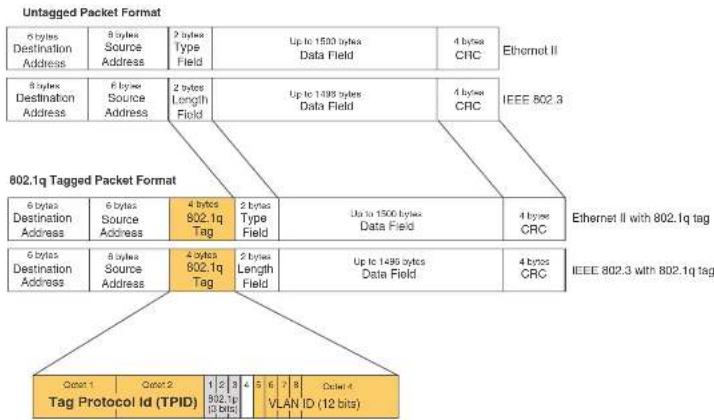
flowchart
graph TD
    A["Untagged Packet Format"] --> B["6 bytes Destination Address"]
    A --> C["8 bytes Source Address"]
    A --> D["2 bytes Type Field"]
    A --> E["Up to 1500 bytes Data Field"]
    A --> F["4 bytes CRC"]
    G["802.1q Tagged Packet Format"] --> H["6 bytes Destination Address"]
    G --> I["8 bytes Source Address"]
    G --> J["4 bytes 802.1q Tag"]
    G --> K["2 bytes Type Field"]
    G --> L["Up to 1500 bytes Data Field"]
    G --> M["4 bytes CRC"]
    N["Tag Protocol Id (TPID)"] --> O["Octat 1"]
    N --> P["Octat 2"]
    N --> Q["1"]
    N --> R["2"]
    N --> S["3"]
    N --> T["4"]
    N --> U["5"]
    N --> V["6"]
    N --> W["7"]
    N --> X["8"]
    N --> Y["Octel-4"]
    Z["Ethernet II"] --> AA["IEEE 802.3"]
    AA --> AB["Ethernet II with 802.1q tag"]
    AB --> AC["6 bytes Destination Address"]
    AB --> AD["8 bytes Source Address"]
    AB --> AE["4 bytes 802.1q Tag"]
    AB --> AF["2 bytes Type Field"]
    AB --> AG["Up to 1495 bytes Data Field"]
    AB --> AH["4 bytes CRC"]
    AI["IEEE 802.3 with 802.1q tag"] --> AJ["6 bytes Destination Address"]
If you configure a VLAN that spans multiple devices, you need to use tagging only if a port connecting one of the devices to the other is a member of more than one port-based VLAN. If a port connecting one device to the other is a member of only a single port-based VLAN, tagging is not required.
If you use tagging on multiple devices, each device must be configured for tagging and must use the same tag value. In addition, the implementation of tagging must be compatible on the devices. The tagging on all Dell PowerConnect devices is compatible with other Dell PowerConnect devices.
Figure 90 shows an example of two devices that have the same Layer 2 port-based VLANs
FIGURE 90 VLANs configured across multiple devices
User-configured port-based VLAN
T = 802.1Q tagged port
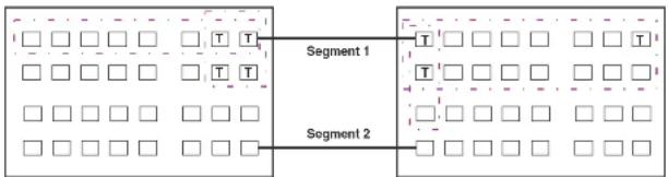
flowchart
graph LR
    A["□ □ □ □ □ T T"] --> B["Segment 1"]
    C["□ □ □ □ □ T T"] --> D["Segment 2"]
    E["□ □ □ □ □ □"] --> F["□ □ □ □ □ □"]
    G["□ □ □ □ □ □"] --> H["□ □ □ □ □ □"]
    I["□ □ □ □ □ □"] --> J["□ □ □ □ □ □"]
    K["□ □ □ □ □ □"] --> L["□ □ □ □ □ □"]
    M["□ □ □ □ □ □"] --> N["□ □ □ □ □ □"]
    O["□ □ □ □ □ □"] --> P["□ □ □ □ □ □"]
Segment 1
Segment 2
Tagging is required for the ports on Segment 1 because the ports are in multiple port-based VLANs.
Tagging is not required for the ports on Segment 2 because each port is in only one port-based VLAN.
Without tagging, a device receiving VLAN traffic from the other device would not be sure which VLAN the traffic is for.
Support for 802.1Q-in-Q tagging
Dell PowerConnect devices provide finer granularity for configuring 802.1Q tagging, enabling you to configure 802.1Q tag-types on a group of ports, thereby enabling the creation of two identical 802.1Q tags (802.1Q-in-Q tagging) on a single device. This enhancement improves SAV interoperability between Dell PowerConnect devices and other vendors' devices that support the 802.1Q tag-types, but are not very flexible with the tag-types they accept.
- PowerConnect B-Series FCX devices support one value for tag-type, which is defined at the global level, and one value for tag-profile, which is defined at the global and interface level of the QII.
To direct individual ports or on a range of ports to this tag profile, enter commands similar to the following.
PowerConnect(config)# interface ethernet 1/1/1
PowerConnect(config-if-ol000-1/1/1)# tag-profile enable
PowerConnect(config-mif-1/1/1,1/2/1)† tag-profile enable
Spanning Tree Protocol (STP)
The default state of STP depends on the device type:
- STP is disabled by default on Layer 3 Switches.
- STP is enabled by default on Layer 2 Switches.
Also by default, each port-based VLAN has a separate instance of STP. Thus, when STP is globally enabled, each port-based VLAN on the device runs a separate spanning tree.
You can enable or disable STP on the following levels:
- Globally – Affects all ports on the device.
NOTE
If you configure a port-based VLAN on the device, the VLAN has the same STP state as the default STP state on the device. Thus, on Layer 2 Switches, new VLANs have STP enabled by default. On Layer 3 Switches, new VLANs have STP disabled by default. You can enable or disable STP in each VLAN separately. In addition, you can enable or disable STP on individual ports.
- Port-based VLAN – Affects all ports within the specified port-based VLAN.
STP is a Layer 2 protocol. Thus, you cannot enable or disable STP for individual protocol VLANs or for IP subnet, IPX network, or AppleTalk cable VLANs. The STP state of a port-based VLAN containing these other types of VLANs determines the STP state for all the Layer 2 broadcasts within the port-based VLAN. This is true even though Layer 3 protocol broadcasts are sent on Layer 2 within the VLAN.
It is possible that STP will block one or more ports in a protocol VLAN that uses a virtual routing interface to route to other VLANs. For IP protocol and IP subnet VLANs, even though some of the
If you want the device to be able to send Layer 3 traffic from one protocol VLAN to another, you must configure a virtual routing interface on each protocol VLAN, then configure routing parameters on the virtual routing interfaces. For example, to enable a Layer 3 Switch to route IP traffic from one IP subnet VLAN to another, you must configure a virtual routing interface on each IP subnet VLAN, then configure the appropriate IP routing parameters on each of the virtual routing interfaces.
Figure 91 shows an example of Layer 3 protocol VLANs that use virtual routing interfaces for routing.
FIGURE 91 Use virtual routing interfaces for routing between Layer 3 protocol VLANs
User-configured port-based VLAN
User-configured protocol VLAN, IP sub-net VLAN,
IPX network VLAN, or AppleTalk cable VLAN
VE = virtual interface
("VE" stands for "Virtual Ethernet")

text_image
VE 1 VE 2 VE 3 VE 4VLAN and virtual routing interface groups
Dell PowerConnect devices support the configuration of VLAN groups. To simplify configuration, you can configure VLAN groups and virtual routing interface groups. When you create a VLAN group, the VLAN parameters you configure for the group apply to all the VLANs within the group. Additionally, you can easily associate the same IP subnet interface with all the VLANs in a group by configuring a virtual routing interface group with the same ID as the VLAN group.
For configuration information, refer to "Configuring VLAN groups and virtual routing interface groups" on page 472.
Dynamic, static, and excluded port membership
When you add ports to a protocol VLAN, IP subnet VLAN, IPX network VLAN, or AppleTalk cable VLAN, you can add them dynamically or statically:
- Dynamic ports
- Static ports
You also can explicitly exclude ports.
Dynamic ports
Dynamic ports are added to a VLAN when you create the VLAN. However, if a dynamically added port does not receive any traffic for the VLAN protocol within ten minutes, the port is removed from the VLAN. However, the port remains a candidate for port membership. Thus, if the port receives traffic for the VLAN protocol, the device adds the port back to the VLAN.
After the port is added back to the VLAN, the port can remain an active member of the VLAN up to 20 minutes without receiving traffic for the VLAN protocol. If the port ages out, it remains a candidate for VLAN membership and is added back to the VLAN when the VLAN receives protocol traffic. At this point, the port can remain in the VLAN up to 20 minutes without receiving traffic for the VLAN protocol, and so on.
Unless you explicitly add a port statically or exclude a port, the port is a dynamic port and thus can be an active member of the VLAN, depending on the traffic it receives.
FIGURE 92 VLAN with dynamic ports—all ports are active when you create the VLAN
A = active port
C = candidate port
When you add ports dynamically,
all the ports are added when you add
the VLAN.
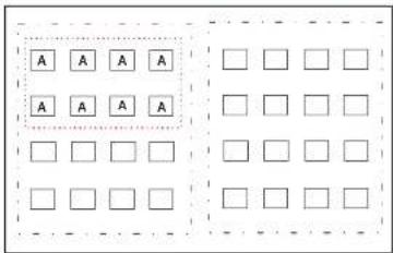
text_image
A A A A A A A A □ □ □ □ □ □ □ □ □ □ □ □SUBNET Ports in a new protocol VLAN that do not receive traffic for the VLAN protocol age out after 10 minutes and become candidate ports. Figure 93 shows what happens if a candidate port receives traffic for the VLAN protocol.
FIGURE 93 VLAN with dynamic ports—candidate ports become active again if they receive protocol traffic
Ports that time out remain candidates
for membership in the VLAN and become active
again if they receive traffic for the VLAN's
protocol, IP sub-net, IPX network, or
AppleTalk cable range.
-
-
-
-
-
-
-
-
-
-
-
- 21.
-
-
-
-
-
-
-
-
-
-
Static ports
Static ports are permanent members of the protocol VLAN. The ports remain active members of the VLAN regardless of whether the ports receive traffic for the VLAN protocol. You must explicitly identify the port as a static port when you add it to the VLAN. Otherwise, the port is dynamic and is subject to aging out.
Excluded ports
If you want to prevent a port in a port-based VLAN from ever becoming a member of a protocol, IP subnet, IPX network, or AppleTalk cable VLAN configured in the port-based VLAN, you can explicitly exclude the port. You exclude the port when you configure the protocol, IP subnet, IPX network, or AppleTalk cable VLAN.
Excluded ports do not leak broadcast packets. Refer to "Broadcast leaks" on page 441.
Broadcast leaks
A dynamic port becomes a member of a Layer 3 protocol VLAN when traffic from the VLAN's protocol is received on the port. After this point, the port remains an active member of the protocol VLAN, unless the port does not receive traffic from the VLAN's protocol for 20 minutes. If the port does not receive traffic for the VLAN's protocol for 20 minutes, the port ages out and is no longer an active member of the VLAN.
To enable a host that has been silent for awhile to send and receive packets, the dynamic ports that are currently members of the Layer 3 protocol VLAN "leak" Layer 3 broadcast packets to the ports that have aged out. When a host connected to one of the aged out ports responds to a leaked broadcast, the port is added to the protocol VLAN again.
To "leak" Layer 3 broadcast traffic, an active port sends 1/8th of the Layer 3 broadcast traffic to the inactive (aged out) ports.
Static ports do not age out and do not leak broadcast packets.
Super aggregated VLANs
Summary of VLAN configuration rules
A hierarchy of VLANs exists between the Layer 2 and Layer 3 protocol-based VLANs:
- Port-based VLANs are at the lowest level of the hierarchy.
- Layer 3 protocol-based VLANs, IP, IPv6, IPX, AppleTalk, Decnet, and NetBIOS are at the middle level of the hierarchy.
• IP subnet, IPX network, and AppleTalk cable VLANs are at the top of the hierarchy.
NOTE
You cannot have a protocol-based VLAN and a subnet or network VLAN of the same protocol type in the same port-based VLAN. For example, you can have an IPX protocol VLAN and IP subnet VLAN in the same port-based VLAN, but you cannot have an IP protocol VLAN and an IP subnet VLAN in the same port-based VLAN, nor can you have an IPX protocol VLAN and an IPX network VLAN in the same port-based VLAN.
As a Dell PowerConnect device receives packets, the VLAN classification starts from the highest level VLAN first. Therefore, if an interface is configured as a member of both a port-based VLAN and an IP protocol VLAN, IP packets coming into the interface are classified as members of the IP protocol VLAN because that VLAN is higher in the VLAN hierarchy.
Multiple VLAN membership rules
- A port can belong to multiple, unique, overlapping Layer 3 protocol-based VLANs without VLAN tagging.
- A port can belong to multiple, overlapping Layer 2 port-based VLANs only if the port is a tagged port. Packets sent out of a tagged port use an 802.1Q-tagged frame.
- When both port and protocol-based VLANs are configured on a given device, all protocol VLANs must be strictly contained within a port-based VLAN. A protocol VLAN cannot include ports from multiple port-based VLANs. This rule is required to ensure that port-based VLANs remain loop-free Layer 2 broadcast domains.
- IP protocol VLANs and IP subnet VLANs cannot operate concurrently on the system or within the same port-based VLAN.
Routing between VLANs
Layer 3 Switches can locally route IP, IPX, and Appletalk between VLANs defined within a single router. All other routable protocols or protocol VLANs (for example, DecNet) must be routed by another external router capable of routing the protocol.
Virtual routing interfaces (Layer 3 Switches only)
You need to configure virtual routing interfaces if an IP, IPX, or Appletalk protocol VLAN, IP subnet VLAN, AppleTalk cable VLAN, or IPX network VLAN needs to route protocols to another port-based VLAN on the same router. A virtual routing interface can be associated with the ports in only a single port-based VLAN. Virtual router interfaces must be defined at the highest level of the VLAN hierarchy.
If you do not need to further partition the port-based VLAN by defining separate Layer 3 VLANs, you can define a single virtual routing interface at the port-based VLAN level and enable IP, IPX, and Appletalk routing on a single virtual routing interface.
Some configurations may require simultaneous switching and routing of the same single protocol across different sets of ports on the same router. When IP, IPX, or Appletalk routing is enabled on a Layer 3 Switch, you can route these protocols on specific interfaces while bridging them on other interfaces. In this scenario, you can create two separate backbones for the same protocol, one bridged and one routed.
To bridge IP, IPX, or Appletalk at the same time these protocols are being routed, you need to configure an IP protocol, IP subnet, IPX protocol, IPX network, or Appletalk protocol VLAN and not assign a virtual routing interface to the VLAN. Packets for these protocols are bridged or switched at Layer 2 across ports on the router that are included in the Layer 3 VLAN. If these VLANs are built within port-based VLANs, they can be tagged across a single set of backbone fibers to create separate Layer 2 switched and Layer 3 routed backbones for the same protocol on a single physical backbone.
Routing between VLANs using virtual routing interfaces
(1 over 2 Switches only)
If your backbone consists of virtual routing interfaces all within the same STP domain, it is a bridged backbone, not a routed one. This means that the set of backbone interfaces that are blocked by STP will be blocked for routed protocols as well. The routed protocols will be able to cross these paths only when the STP state of the link is FORWARDING. This problem is easily avoided by proper network design.
When designing an ISR network, pay attention to your use of virtual routing interfaces and the spanning-tree domain. If Layer 2 switching of your routed protocols (IP, IPX, AppleTalk) is not required across the backbone, then the use of virtual routing interfaces can be limited to edge switch ports within each router. Full backbone routing can be achieved by configuring routing on each physical interface that connects to the backbone. Routing is independent of STP when configured on a physical interface.
If your ISR design requires that you switch IP, IPX, or Appletalk at Layer 2 while simultaneously routing the same protocols over a single backbone, then create multiple port-based VLANs and use VLAN tagging on the backbone links to separate your Layer 2 switched and Layer 3 routed networks.
There is a separate STP domain for each port-based VLAN. Routing occurs independently across port-based VLANs or STP domains. You can define each end of each backbone link as a separate tagged port-based VLAN. Routing will occur independently across the port-based VLANs. Because each port-based VLAN STP domain is a single point-to-point backbone connection, you are guaranteed to never have an STP loop. STP will never block the virtual router interfaces within the tagged port-based VLAN, and you will have a fully routed backbone.
Dynamic port assignment (Layer 2 Switches and Layer 3 Switches)
All Switch ports are dynamically assigned to any Layer 3 VLAN on Layer 2 Switches and any non-routable VLAN on Layer 3 Switches. To maintain explicit control of the VLAN, you can explicitly exclude ports when configuring any Layer 3 VLAN on a Layer 2 Switch or any non-routable Layer 3 VLAN on a Layer 3 Switch.
If you do not want the ports to have dynamic membership, you can add them statically. This eliminates the need to explicitly exclude the ports that you do not want to participate in a particular
NOTE
does not change the properties of the default VLAN. Changing the name allows you to use the VLAN ID "1" as a configurable VLAN.
Assigning different VLAN IDs to reserved VLANs 4091 and 4092
If you want to use VLANs 4091 and 4092 as configurable VLANs, you can assign them to different VLAN IDs.
For example, to reassign reserved VLAN 4091 to VLAN 10, enter the following commands.
PowerConnect(config)# reserved vlan map vlan 4091 new vlan 10 Reload required. Please write memory and then reload or power cycle. PowerConnect(config)# write mem PowerConnect(config)# exit PowerConnect# reload
NOTE
You must save the configuration (write mem) and reload the software to place the change into effect.
The above configuration changes the VLAN ID of 4091 to 10. After saving the configuration and reloading the software, you can configure VLAN 4091 as you would any other VLAN.
Syntax: [no] reserved-vlan-map vlan 4091 | 4092 new-vlan
For
Viewing reassigned VLAN IDs for reserved VLANs 4091 and 4092
To view the assigned VLAN IDs for reserved VLANs 4091 and 4092, use the show reserved-vlan-map command. The reassigned VLAN IDs also display in the output of the show running config and show config commands.
TABLE 77 Output of the show reserved-vlan-map command (Continued)
| This field Displays | |
| Re-assign The VLAN ID to which the reserved VLAN was reassigned. | 1 |
| Current The current VLAN ID for the reserved VLAN. | 1 |
- If you reassign a reserved VLAN without saving the configuration and reloading the software, the reassigned VLAN ID will display in the Re-assign column. However, the previously configured or default VLAN ID will display in the Current column until the configuration is saved and the device reloaded.
Assigning trunk group ports
When a "lead" trunk group port is assigned to a VLAN, all other members of the trunk group are automatically added to that VLAN. A lead port is the first port of a trunk group port range; for example, "1" in 1 - 4 or "5" in
5 - 8. Refer to "Trunk group rules" on page 395 for more information.
Configuring port-based VLANs
Port-based VLANs allow you to provide separate spanning tree protocol (STP) domains or broadcast domains on a port-by-port basis.
This section describes how to perform the following tasks for port-based VLANs using the CLI:
- Create a VLAN
- Delete a VLAN
- Modify a VLAN
- Change a VLAN priority
- Enable or disable STP on the VLAN
Example 1
Figure 94 shows a simple port-based VLAN configuration using a single Layer 2 Switch. All ports
FIGURE 94 Port-based VLANs 222 and 333
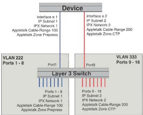
flowchart
graph TD
    A["Device"] -->|interface e 1\nIP Subnet 1\nIPX Network 1\nAppletalk Cable-Range 100\nAppletalk Zone Prepress| B["Layer 3 Switch"]
    A -->|interface e 2\nIP Subnet 2\nIPX Network 2\nAppletalk Cable-Range 200\nAppletalk Zone CTP| C["VLAN 222 Ports 1 - 8"]
    A -->|interface e 2\nIP Subnet 2\nIPX Network 2\nAppletalk Cable-Range 200\nAppletalk Zone CTP| D["VLAN 333 Ports 9 - 16"]
    B -->|Port1| E["Ports 1 - 8\nIP Subnet 1\nIPX Network 1\nAppletalk Cable-Range 100\nAppletalk Zone Prepress"]
    B -->|Port9| F["Ports 9 - 16\nIP Subnet 2\nIPX Network 2\nAppletalk Cable-Range 200\nAppletalk Zone CTP"]
To create the two port-based VLANs shown in Figure 94, enter the following commands.
PowerConnect(config)# vlan 222 by port
PowerConnect(config-vian-222)† untagged ethernet 1 to 3
PowerConnect (config-vian-222)↑ vlan 333 by port
PowerConnect(config-vlan-333)† untagged ethernet 9 to 16
Syntax: vlan
FIGURE 95 More complex port-based VLAN
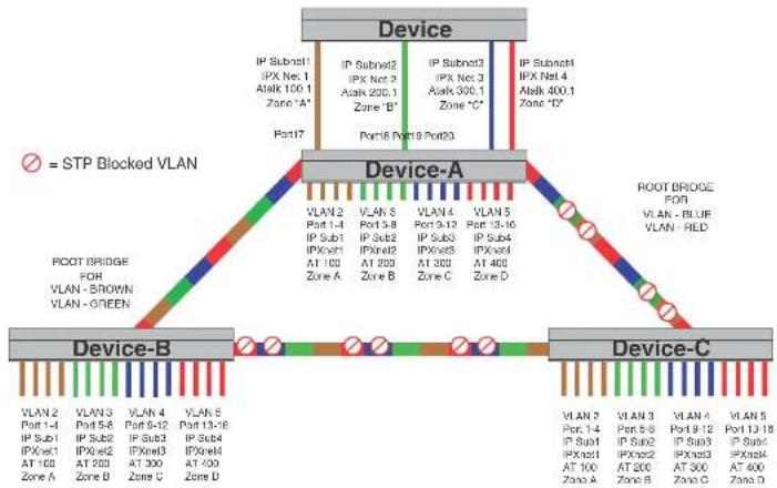
flowchart
graph TD
    A["Device"] -->|IP Subnet1 IPX Net 1 Alak 100.1 Zone 'A'| B["Device-A"]
    A -->|IP Subnet2 IPX Net 2 Alak 200.1 Zone 'B'| B
    A -->|IP Subnet3 IPX Net 3 Alak 300.1 Zone 'C'| B
    A -->|IP Subnet4 IPX Net 4 Alak 400.1 Zone 'D'| B
    B --> C["Device-B"]
    B --> D["Device-C"]
    C --> E["Plant"]
    C --> F["Plant"]
    D --> G["Plant"]
    D --> H["Plant"]
    style A fill:#f9f,stroke:#333
    style B fill:#ccf,stroke:#333
    style C fill:#cfc,stroke:#333
    style D fill:#fcc,stroke:#333
To configure the Port-based VLANs on the Layer 2 Switches in Figure 95, use the following method.
Configuring device-A
Enter the following commands to configure device-A.
PowerConnect> enable
PowerConnect configure terminal
Configuring device-B
Enter the following commands to configure device-B.
PowerConnect> en
PowerConnect configuration terminal
PowerConnect{config}# hostname PowerConnect-B
PowerConnect-B (config) # vlan 2 name BROWN
PowerConnect-B(config-vlan-2)† untagged ethernet 1 to 4
PowerConnect-B(config-vlan-2)# tagged ethernet 25 to 26
PowerConnect-B(config-vlan-2)↑ spanning-tree
PowerConnect-B(config-vlan-2)† spanning-tree priority 500
PowerConnect-B(config-vlan-2)↓ vlan 3 name GREEN
PowerConnect-B(config-vlan-3)† untagged ethernet 5 to 8
PowerConnect-B(config-vlan-3) + tagged ethernet 25 to 26
PowerConnect-B(config-vlan-3) ↑ spanning-tree
PowerConnect B(config vlan 3) # spanning tree priority 500
PowerConnect-R (config-vlan-3) vlan 4 name BLUE
PowerConnect-B(config-vlan-4)† untagged ethernet 9 to 12
PowerConnect-B(config-vlan-4)‡ tagged ethernet 25 to 26
PowerConnect-E(config-vlan-4)† vlan 5 name RED
PowerConnect-B(config-vlan-5)† untagged ethernet 13 to 16
PowerConnect-B(config-vlan-5)↓ tagged ethernet 25 to 26
PowerConnect-B(config-vlan-5)† end
PowerConnect-B4 write memory
Configuring device-C
Enter the following commands to configure device C.
PowerConnect> en
PowerConnect# configure terminal
PowerConnect(config)# hostname PowerConnect-C
PowerConnect-C(config)# vlan 2 name BROWN
PowerConnect C(config vlan 2) ≠ untagged ethernet 1 to 4
PowerConnect-C(config-vlan-2)↓ tagged ethernet 25 to 26
PowerConnect-C(config-vlan-2)† vlan 3 name GREEN
PowerConnect-C (config-vlan-3) + untagged ethernet 5 to 8
PowerConnect-C(config-vlan-3)† tagged ethernet 25 to 26
Modifying a port-based VLAN
You can make the following modifications to a port-based VLAN:
- Add or delete a VLAN port.
- Enable or disable STP.
Removing a port-based VLAN
Suppose you want to remove VLAN 5 from the example in Figure 95. To do so, use the following procedure.
- Access the global CONFIG level of the CLI on device-A by entering the following commands.
PowerConnect-A> enable
No password has been assigned yet...
PowerConnect-A# configure terminal
PowerConnect-A(config)#
- Enter the following command.
PowerConnect-A(config)# no vlan 5
PowerConnect-A(config)#
- Enter the following commands to exit the CONFIG level and save the configuration to the system-config file on flash memory.
PowerConnect-A(config)#
PowerConnect-A(config)# end
PowerConnect-A# write memory
PowerConnect-A#
- Repeat steps 1 - 3 on device-B.
Syntax: no vlan
Removing a port from a VLAN
Suppose you want to remove port 11 from VLAN 4 on device-A shown in Figure 95. To do so, use
- Enter the following commands to exit the VLAN CONFIG mode and save the configuration to the system-config file on flash memory.
PowerConnect-A(config-vlan-4)†
PowerConnect-A(config-vlan-4)† and
PowerConnect-A# write memory
You can remove all the ports from a port-based VLAN without losing the rest of the VLAN configuration. However, you cannot configure an IP address on a virtual routing interface unless the VLAN contains ports. If the VLAN has a virtual routing interface, the virtual routing interface IP address is deleted when the ports associated with the interface are deleted. The rest of the VLAN configuration is retained.
Enable spanning tree on a VLAN
The spanning tree bridge and port parameters are configurable using one CLI command set at the Global Configuration Level of each Port-based VLAN. Suppose you want to enable the IEEE 802.1D STP across VLAN 3. To do so, use the following method.
NOTE
When port-based VLANs are not operating on the system, STP is set on a system-wide level at the global CONFIG level of the CLI.
- Access the global CONFIG level of the CLI on device-A by entering the following commands.
PowerConnect-A> enable
No password has been assigned yet...
PowerConnect-A# configure terminal
PowerConnect-A(config)#
- Access the level of the CLI for configuring port-based VLAN 3 by entering the following command.
PowerConnect-A(config)#
PowerConnect-A(config)# vlan 3
PowerConnect-A(config-vlan-3)#
- From VLAN 3 configuration level of the CLI, enter the following command to enable STP on all
To configure a specific path-cost or priority value for a given port, enter those values using the key words in the brackets [ ] shown in the syntax summary below. If you do not want to specify values for any given port, this portion of the command is not required.
Syntax: vlan
Syntax: [no] spanning-tree
Syntax: spanning-tree [ethernet [
Bridge STP parameters (applied to all ports within a VLAN):
- Forward Delay – the period of time a bridge will wait (the listen and learn period) before forwarding data packets. Possible values: 4 – 30 seconds. Default is 15.
- Maximum Age – the interval a bridge will wait for receipt of a hello packet before initiating a topology change. Possible values: 6 – 40 seconds. Default is 20.
- Hello Time – the interval of time between each configuration BPDU sent by the root bridge. Possible values: 1 – 10 seconds. Default is 2.
- Priority – a parameter used to identify the root bridge in a network. The bridge with the lowest value has the highest priority and is the root. Possible values: 1 – 65,535. Default is 32,678.
Port parameters (applied to a specified port within a VLAN):
- Path Cost – a parameter used to assign a higher or lower path cost to a port. Possible values: 1 – 65535. Default is (1000/Port Speed) for Half-Duplex ports and is (1000/Port Speed)/2 for Full-Duplex ports.
- Priority – value determines when a port will be rerouted in relation to other ports. Possible values: 0 – 255. Default is 128.
Configuring IP subnet, IPX network and protocol-based VLANs
Protocol-based VI ANs provide the ability to define separate broadcast domains for several unique
FIGURE 96 Protocol-based (Layer 3) VLANs
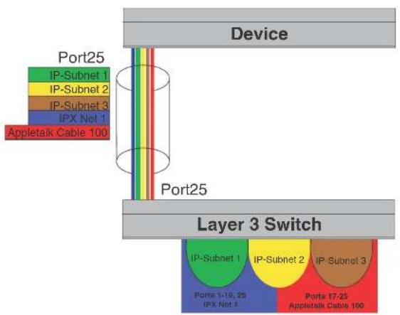
flowchart
graph TD
    A["Device"] --> B["Port25"]
    B --> C["Layer 3 Switch"]
    C --> D["Port25"]
    D --> E["Appletalk Cable 100"]
    style A fill:#f9f,stroke:#333
    style B fill:#ccf,stroke:#333
    style C fill:#cfc,stroke:#333
    style D fill:#fcc,stroke:#333
To configure the VLANs shown in Figure 96, use the following procedure.
- To permanently assign ports 1 - 8 and port 25 to IP subnet VLAN 1.1.1.0, enter the following commands.
PowerConnect(config-vlan-2)# ip-subnet 1.1.1.0/24 name Green
PowerConnect(config-vlan-ip-subnet)↑ static ethernet 1 to 8 ethernet 25
- To permanently assign ports 9 - 16 and port 25 to IP subnet VLAN 1.1.2.0, enter the following commands
Configuring IP subnet, IPX network, and protocol-based VLANs within port-based VLANs
PowerConnect(config-lpx-proto)# atalk-proto name Red
PowerConnect(config-atalk-proto)† no dynamic
PowerConnect(config-atalk-proto)‡ static ethernet 13 to 25
PowerConnect(config-atalk-proto)† end
PowerConnect# write memory
PowerConnect#
Syntax: Ip-subnet
Syntax: lpx-network <lpx-network-number> <frame-encapsulation-type> netbios-allow | netbios-disallow
[name <string>]
Syntax: ip-proto | ipx-proto | atalk-proto | decnet-proto | netbios-proto | other-proto static | exclude | dynamic ethernet [<slotnum>/]<portnum> [to [<slotnum>/]<portnum>] [name <string>]
Configuring IP subnet, IPX network, and protocol-based VLANs within port-based VLANs
If you plan to use port-based VLANs in conjunction with protocol-based VLANs, you must create the port-based VLANs first. Once you create a port-based VLAN, then you can assign Layer 3 protocol VLANs within the boundaries of the port-based VLAN. Generally, you create port-based VLANs to allow multiple separate STP domains.
Example
Suppose you need to provide three separate STP domains across an enterprise campus backbone. The first STP domain (VLAN 2) requires a set of ports at each Layer 2 Switch location to be statically mapped to IP only. No other protocols can enter the switches on this set of ports.
A second set of ports within STP domain VLAN 2 will be restricted to only IPX traffic. The IP and IPX protocol VLANs will overlap on Port 1 of device-A to support both protocols on the same router interface. The IP subnets and IPX network that span the two protocol VLANs will be determined by the PowerConnect router configuration. The IP and IPX Protocol VLANs ensure that only the ports included in the each Layer 3 protocol VLAN will see traffic from the PowerConnect router.
Configuring IP subnet, IPX network, and protocol-based VLANs within port-based VLANs
FIGURE 97 More protocol-based VLANs
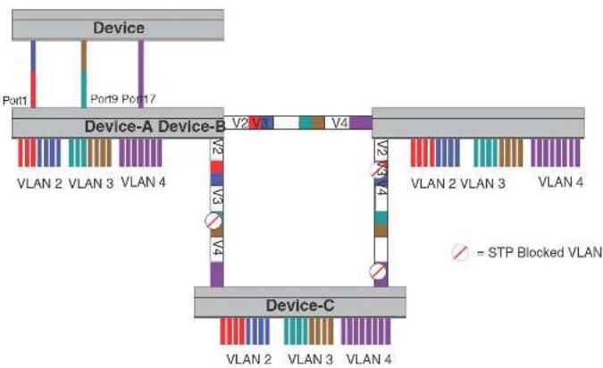
flowchart
graph TD
    A["Device"] --> B["Port1"]
    A --> C["Port9 Port17"]
    A --> D["Device-A Device-B"]
    A --> E["Device-C"]
    B --> F["VLAN 2 VLAN 3 VLAN 4"]
    C --> G["VLAN 2 VLAN 3 VLAN 4"]
    D --> H["VLAN 2 VLAN 3 VLAN 4"]
    E --> I["VLAN 2 VLAN 3 VLAN 4"]
    style A fill:#f9f,stroke:#333
    style B fill:#ccf,stroke:#333
    style C fill:#cfc,stroke:#333
    style D fill:#fcc,stroke:#333
    style E fill:#cff,stroke:#333
    note right of E: = STP Blocked VLAN
To configure the Layer 3 VLANs on the Layer 2 Switches in Figure 97, use the following procedure.
Configuring device-A
Enter the following commands to configure device-A.
- Create port-based VLAN 2 and assign the untagged and tagged ports that will participate in this VLAN.
PowerConnect-A >en
-
-
-
-
-
-
-
-
-
-
-
-
-
-
-
-
-
-
-
-
-
-
-
-
-
-
-
-
-
-
-
-
-
-
-
-
-
-
-
-
-
-
-
-
-
-
-
-
-
-
-
-
-
-
-
-
-
-
-
-
-
-
-
-
-
-
-
-
-
-
-
-
-
-
-
-
-
-
-
-
-
-
-
-
-
-
-
-
-
- 91.
-
-
-
-
-
-
-
-
-
-
-
-
-
-
-
-
-
-
-
-
-
-
-
-
-
-
-
-
-
-
-
-
-
-
-
-
-
-
-
-
-
-
-
-
-
-
-
-
-
-
-
-
-
-
-
-
-
-
-
-
-
-
-
-
-
-
-
-
-
-
-
-
-
-
-
-
-
-
-
-
-
-
-
-
-
-
-
-
-
To prevent machines with non-IP protocols from getting into the IP portion of VLAN 2, create another Layer 3 protocol VLAN to exclude all other protocols from the ports that contains the IP-protocol VLAN. To do so, enter the following commands.
PowerConnect-A(config-vlan-ipx-proto)# other-proto name Block_other_proto
PowerConnect-A(config-vlan-other-proto) # no dynamic
PowerConnect-A(config-vlan-other-proto) # exclude el to 8
PowerConnect-A(config-vlan-other-proto) #
- Create port-based VLAN 3. Note that device-B will be the root for this STP domain, so you do not need to adjust the STP priority.
PowerConnect-A(config vlan other proto)# vlan 3 name IP Sub_IPX Net_VIans
PowerConnect-A(config-vlan-3)# untagged e9 to 16
PowerConnect-A(config-vlan-3)# tagged e25 to 26
PowerConnect-A(config-vlan-3)# spanning tree
PowerConnect-A(config-vlan-3)#
- Create IP subnet VLAN 1.1.1.0/24, IPX network 1, and other-protocol VLANs
PowerConnect-A(config-vlan-3)† ip-subnet 1.1.1.0/24 name Green
PowerConnect-A(config-vlan-ip-subnet)‡ no dynamic
PowerConnect-A(config-vlan-ip-subnet)‡ static e9 to 12 e25 to 26
PowerConnect-A(config-vlan-ip-subnot)‡ exclude e13 to 16
PowerConnect-A(config-vlan-ip-subnet)‡ ipx net 1 ethernet_802.3 name Brown
PowerConnect-A(config-vlan-ipx-network)‡ no dynamic
PowerConnect-A(config-vlan-ipx-network)‡ static e9 e13 to 16 e29 to 26
PowerConnect-A(config-vlan-ipx-network)‡ exclude e10 to 12
PowerConnect-A(config-vlan-ipx-network)‡ other-proto name Block_other_proto
PowerConnect-A(config-vlan-other-proto)‡ no dynamic
PowerConnect-A(config-vlan-other-proto)‡ exclude e9 to 16
PowerConnect-A(config-vlan-other-proto)‡
- Configure the last port-based VLAN 4. You need to set the STP priority for this VLAN because device-A will be the root bridge for this VLAN. Because you do not need to partition this STP domain into multiple Layer 3 broadcast domains, this is the only configuration required for VLAN 4.
PowerConnect A(config vlan-other proto)# vlan 4 name Purple_ALL-Protocols
PowerConnect-A(config-vlan-4)# untagged e17 to 24
PowerConnect-A(config-vlan-4)# tagged e25 to 26
Configuring IP subnet, IPX network, and protocol-based VLANs within port-based VLANs
PowerConnect-P(config-vlan-ipx-proto)† static e5 to 8 e25 to 26
PowerConnect-B(config-vlan-ipx-proto)† exclude e1 to 4
PowerConnect-B(config-vlan-other-proto)‡ vlan 3 name IP-Sub_TPX-Nel_VLANs
PowerConnect-P(config-vlan-3)† untagged e9 to 16
PowerConnect-B(config-vlan-3)‡ lagged e25 to 26
PowerConnect-B(config-vlan-3)‡ spanning-tree
PowerConnect-B(config-vlan-3)‡ spanning-tree priority 500
PowerConnect-B(config-vlan-3)‡ ip-sub 1.1.1.0/24 name Green
PowerConnect-B(config-vlan-ip-subnot)‡ no dynamic
PowerConnect-B(config-vlan ip-subnet)‡ static e9 to 12 e25 to 26
PowerConnect-B(config-vlan-ip-subnot)‡ exclude e13 to 16
PowerConnect-B(config-vlan-ip-subnet)‡ ipx-net i ethernet_802.3 name Brown
PowerConnect-B(config-vlan-ipx-network)‡ no dynamic
PowerConnect-B(config-vlan-ipx-network)‡ static e13 to 16 e25 to 26
PowerConnect-B(config-vlan-ipx-network)‡ exclude e9 to 12
PowerConnect-B(config-vlan-ipx-network)‡ vlan 4 name Purple_MLL-Protocols
PowerConnect-B(config-vlan-4)‡ untagged e17 to 24
PowerConnect-B(config-vlan-4)‡ Lagged e25 to 26
PowerConnect-B(config-vlan-4)‡ spanning-tree
Configuring device-C
Enter the following commands to configure device-C.
PowerConnect# config t
PowerConnect(config)# host PowerConnect-C
PowerConnect-C(config)† vlan 2 name IP_IPX_Protocol
PowerConnect-C(config-vlan-2)‡ untagged el 1 to 8
PowerConnect-C(config-vlan-2)‡ tagged e25 to 26
PowerConnect-C(config-vlan-2)‡ spanning tree
PowerConnect-C(config-vlan-2)‡ ip-proto name Red
PowerConnect-C(config-vlan-ip-proto)† no dynamic
PowerConnect-C(config-vlan-ip-proto)‡ static el 1 to 4 e25 to 26
PowerConnect-C(config-vlan-ip-proto)† exclude e5 to 8
PowerConnect-C(config-vlan ip-proto)‡ ipx proto name Blue
PowerConnect-C(config-vlan-ipx-proto)† no dynamic
PowerConnect-C(config-vlan-ipx-proto)‡ static e5 to 8 e25 to 26
PowerConnect-C(config-vlan-ipx-proto)‡ exclude el 1 to 4
PowerConnect-C(config-vlan-other-proto)‡ vlan 3 name IP-Sub_IDX-Not_VLANs
Configuring an IPv6 protocol VLAN
You can configure a protocol-based VLAN as a broadcast domain for IPv6 traffic. When the Layer 3 Switch receives an IPv6 multicast packet (a packet with 06 in the version field and 0xFF as the beginning of the destination address), the Layer 3 Switch forwards the packet to all other ports.
NOTE
The Layer 3 Switch forwards all IPv6 multicast packets to all ports except the port that received the packet, and does not distinguish among subnet directed multicasts.
You can add the VLAN ports as static ports or dynamic ports. A static port is always an active member of the VLAN. Dynamic ports within any protocol VLAN age out after 10 minutes if no member protocol traffic is received on a port within the VLAN. The aged out port, however, remains as a candidate dynamic port for that VLAN. The port becomes active in the VLAN again if member protocol traffic is received on that port.
Once a port is re-activated, the aging out period for the port is reset to 20 minutes. Each time a member protocol packet is received by a candidate dynamic port (aged out port) the port becomes active again and the aging out period is reset for 20 minutes.
NOTE
You can disable VLAN membership aging of dynamically added ports. Refer to "Disabling membership aging of dynamic VLAN ports" on page 465).
To configure an IPv6 VLAN, enter commands such as the following.
PowerConnect(config)≠ vlan 2
PowerConnect(config-vlan-2)# untagged ethernet 1/1 to 1/8
PowerConnect(config-vlan-2)# ipv6-proto name V6
PowerConnect(config-ipv6-subnet)↑ static ethernet 1/1 to 1/6
PowerConnect(config-ipv6-subnet) # dynamic
The first two commands configure a port-based VLAN and add ports 1/1 - 1/8 to the VLAN. The remaining commands configure an IPv6 VLAN within the port-based VLAN. The static command adds ports 1/1 - 1/6 as static ports, which do not age out. The dynamic command adds the remaining ports, 1/7 - 1/8, as dynamic ports. These ports are subject to aging as described
Routing between VLANs using virtual routing interfaces (Layer 3 Switches only)
Example
Suppose you want to move routing out to each of three buildings in a network. Remember that the only protocols present on VLAN 2 and VLAN 3 are IP and IPX. Therefore, you can eliminate tagged ports 25 and 26 from both VLAN 2 and VLAN 3 and create new tagged port-based VLANs to support separate IP subnets and IPX networks for each backbone link.
You also need to create unique IP subnets and IPX networks within VLAN 2 and VLAN 3 at each building. This will create a fully routed IP and IPX backbone for VLAN 2 and VLAN 3. However, VLAN 4 has no protocol restrictions across the backbone. In fact there are requirements for NetBIOS and DecNet to be bridged among the three building locations. The IP subnet and IPX network that exists within VLAN 4 must remain a flat Layer 2 switched STP domain. You enable routing for IP and IPX on a virtual routing interface only on device-A. This will provide the flat IP and IPX segment with connectivity to the rest of the network. Within VLAN 4 IP and IPX will follow the STP topology. All other IP subnets and IPX networks will be fully routed and have use of all paths at all times during normal operation.
Figure 98 shows the configuration described above.
FIGURE 98 Routing between protocol-based VLANs
Building 1 Building 2
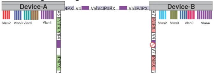
text_image
Device-A Vlan2 Vlan8 Vlan3 Vlan4 V5 IP/IPX V4 V5 IP/IPX V4 V5 IP/IPX Device-B V7 IP/IPX V4 V7 IP/IPX V4 V7 IP/IPX V4 V7 IP/IPX V4 V7 IP/IPX V4 V7 IP/IPX V4 V7 IP/IPX V4PowerConnect>en
No password has been assigned yet...
PowerConnect ^1 configure Terminal
PowerConnect(config)# hostname PowerConnect-A
PowerConnect-A(config)# router ospf
PowerConnect-A(config-ospf-router) # area 0.0.0.0 normal
Please save configuration to flash and reboot.
PowerConnect-A (config-ospf-router)
The following commands create the port-based VLAN 2. In the previous example, an external device defined the router interfaces for VLAN 2. With ISR, routing for VLAN 2 is done locally within each device. Therefore, there are two ways you can solve this problem. One way is to create a unique IP subnet and IPX network VLAN, each with its own virtual routing interface and unique IP or IPX address within VLAN 2 on each device. In this example, this is the configuration used for VLAN 3. The second way is to split VLAN 2 into two separate port-based VLANs and create a virtual router interface within each port-based VLAN. Later in this example, this second option is used to create a port-based VLAN 8 to show that there are multiple ways to accomplish the same task with ISR.
You also need to create the Other-Protocol VLAN within port-based VLAN 2 and 8 to prevent unwanted protocols from being Layer 2 switched within port-based VLAN 2 or 8. Note that the only port-based VLAN that requires STP in this example is VLAN 4. You will need to configure the rest of the network to prevent the need to run STP.
PowerConnect-A(config-ospf-router)# vlan 2 name IP-Subnet_1.1.2.0/24
PowerConnect-A(config-vlan-2)↑ untagged ethernet 1 to 4
PowerConnect-A(config-vlan-2) # no spanning-tree
PowerConnect-A(config-vlan-2) + router-interface vel
PowerConnect-A(config-vlan-2)† other-proto name block_other_protocols
PowerConnect A(config vlan other proto)# no dynamic
PowerConnect-A(config-vlan-other-proto)# exclude ethernet 1 to 4
Once you have defined the port-based VLAN and created the virtual routing interface, you need to configure the virtual routing interface just as you would configure a physical interface.
PowerConnect-A(config-vlan-other-prob)# interface vel
PowerConnect-A(config-vif-1)† ip address 1.1.2.1/24
PowerConnect-A(config-vif-1)‡ ip ospf area 0.0.0.0
Do the same thing for VLAN 8.
Routing between VLANs using virtual routing interfaces (Layer 3 Switches only)
PowerConnect-A(config-vlan-ip-subnet)† ipx-network 1 ethernet_802.3
PowerConnect-A(config-vlan-ipx-network)† static ethernet 13 to 16
PowerConnect-A(config-vlan-ipx-network)† router-interface ve4
PowerConnect-A(config-vlan-ipx-network)† other-proto name block-other-protocols
PowerConnect-A(config-vlan-other-proto)† exclude ethernet 9 to 16
PowerConnect-A(config-vlan-other-proto)† no dynamic
PowerConnect-A(config-vlan-other-proto)† interface ve 3
PowerConnect-A(config-vif-3)† ip addr 1.1.1.1/24
PowerConnect-A(config-vif-3)† ip ospf area 0.0.0.0
PowerConnect-A(config-vif 3)† interface ve4
PowerConnect-A(config-vif-4)† ipx network 1 ethernet_802.3
PowerConnect-A(config-vif-4)†
Now configure VLAN 4. Remember this is a flat segment that, in the previous example, obtained its IP default gateway and IPX router services from an external device. In this example, device-A will provide the routing services for VLAN 4. You also want to configure the STP priority for VLAN 4 to make device-A the root bridge for this VLAN.
PowerConnect-A(config-vif-4)† vlan 4 name Bridged_MU_Protocols
PowerConnect-A(config-vlan-4)† untagged ethernet 17 to 24
PowerConnect-A(config-vlan-4)‡ lagged ethernet 25 to 26
PowerConnect-A(config-vlan-4)‡ spanning-tree
PowerConnect-A(config-vlan-4)‡ spanning tree priority 500
PowerConnect-A(config-vlan-4)‡ router-interface ve5
PowerConnect-A(config-vlan-4)‡ interlace ve5
PowerConnect-A(config-vif-5)‡ ip address 1.1.3.1/24
PowerConnect-A(config-vif-5)‡ ip ospf area 0.0.0.0
PowerConnect-A(config-vif-5)‡ ipx network 3 ethernet_802.3
PowerConnect-A(config-vif-5)‡
It is time to configure a separate port-based VLAN for each of the routed backbone ports (Ethernet 25 and 26). If you do not create a separate tagged port-based VLAN for each point-to-point backbone link, you need to include tagged interfaces for Ethernet 25 and 26 within VLANs 2, 3, and 8. This type of configuration makes the entire backbone a single STP domain for each VLAN 2, 3, and 8. This is the configuration used in the example in "Configuring IP subnet, IPX network and protocol-based VLANs" on page 452. In this scenario, the virtual routing interfaces within port-based VLANs 2, 3, and 8 will be accessible using only one path through the network. The path that is blocked by STP is not available to the routing protocols until it is in the STR FORWARDING state.
This completes the configuration for device-A. The configuration for device-B and C is very similar except for a few issues which are as follows:
- IP subnets and IPX networks configured on device-B and device-C must be unique across the entire network, except for the backbone port-based VLANs 5, 6, and 7 where the subnet is the same but the IP address must change.
- There is no need to change the default priority of STP within VLAN 4.
• There is no need to include a virtual router interface within VLAN 4. - The backbone VLAN between device-B and device-C must be the same at both ends and requires a new VLAN ID. The VLAN ID for this port-based VLAN is VLAN 7.
Configuration for device-B
Enter the following commands to configure device-B.
PowerConnect> en
No password has been assigned yet...
PowerConnect# config t
PowerConnect(config)# hostname PowerConnect-B
PowerConnect-B(config)# router ospf
PowerConnect-B(config-ospf-router)# area 0.0.0.0 normal
PowerConnect-P(config-ospf-router)# router ipx
PowerConnect-B(config-ospf-router)# vlan 2 name IP-Subnet 1.1.6.0/24
PowerConnect-P(config-vlan-2)† untagged ethernet 1 to 4
PowerConnect-P(config-vlan-2)† no spanning-tree
PowerConnect-P(config-vlan-2)† router-interface vel
PowerConnect-P(config-vlan-2)† other-proto name block-other-protocols
PowerConnect-P(config-vlan-other-proto)# no dynamic
PowerConnect-P(config-vlan-other-proto)# exclude ethernet 1 to 4
PowerConnect-P(config-vlan-other-proto)# interface vel
PowerConnect-P(config-vif-1)† ip addr 1.1.6.1/24
PowerConnect-P(config-vif-1)† ip ospf area 0.0.0.0
PowerConnect-P(config-vif-1)† vlan 8 name IPX Network6
PowerConnect-P(config-vlan-8)† untagged ethernet 5 to 8
PowerConnect-P(config-vlan-8)† no span
PowerConnect-P(config-vlan-8)† router-interface ve2
PowerConnect-P(config-vlan-8)† other-proto name block-other-protocols
Routing between VLANs using virtual routing interfaces (Layer 3 Switches only)
PowerConnect-P(config-vif-4) ipx network 7 ethernet_802.3
PowerConnect-B(config-v1f-4) # vlan 4 name Bridged_ALL_Protocols
PowerConnect-R(config-vlan-4)‡ untagged ethernet. 17 to 24
PowerConnect-B(config-vlan-4)† tagged ethernet 25 to 26
PowerConnect-B(config-vlan-4) ≠ spanning-tree
PowerConnect-B(config-vlan-4)← vlan 5 name Rtr_PB_to_Bldg.1
PowerConnect-B(config-vlan-5)‡ tagged ethernet 25
PowerConnect-B (config-vlan-5) + no spanning-tree
PowerConnect-B(config-vlan-5)† router-interface ve5
PowerConnect B(config vlan 5) # vlan 7 name Rtr BB to Bldg.3
PowerConnect-B(config-vlan-7)↑ tagged ethernet 26
PowerConnect-B(config-vlan-7)† no spanning-tree
PowerConnect-P(config-vlan-7)↓ router-interface ve6
PowerConnect-B(config-vlan-7)† interface ve5
PowerConnect-B(config-vif-5)4 ip addr 1.1.4.2/24
PowerConnect-P(config-vif-5)↑ ip ospf area 0.0.0.0
PowerConnect B(config vif 5)‡ 1px network 4 ethernet_802.3
PowerConnect-R (config-vif-5) 4 interface ve6
PowerConnect-B(config-vif-6)† ip addr 1.1.8.1/24
PowerConnect-B(config-vif-6)‡ ip ospf area 0.0.0.0
PowerConnect-R(config-vif-6)† ipx network 8 ethernet 802.3
PowerConnect-B (config-v1f-6)
Configuration for device-C
Enter the following commands to configure device-C.
PowerConnect> en
No password has been assigned yet...
PowerConnect# config
PowerConnect(config)# hostname PowerConnect-C
PowerConnect-C(config)# router ospf
PowerConnect-C(config-ospf-router)# area 0.0.0.0 normal
PowerConnect-C(config-ospf-router)# router 1px
PowerConnect C(config ospf router)# vlan 2 name IP Subnet 1.1.9.0/24
PowerConnect-C(config-vlan-2)↑ untagged ethernet 1 to 4
PowerConnect-C(config-vlan-2)† no spanning-tree
PowerConnect-C (config-vlan-2) + router-interface vel
PowerConnect-C(config-vlan-2)† other-proto name block-other-protocols
PowerConnect-C(config-vlan-ip-subnet)† ipx-network 10 ethernet_802.3
PowerConnect-C(config-vlan-ips-network)† static ethernet 13 to 16
PowerConnect-C(config-vlan-ips-network)† router-interface ve4
PowerConnect-C(config-vlan-ips-network)† other-proto name block-other-protocols
PowerConnect-C(config-vlan-other-proto)† exclude ethernet 9 to 16
PowerConnect-C(config-vlan-other-proto)† no dynamic
PowerConnect-C(config-vlan-other-proto)† interface ve 3
PowerConnect-C(config-vif-3)† ip addr 1.1.10.1/24
PowerConnect-C(config-vif-3)† ip ospf area 0.0.0.0
PowerConnect-C(config-vif-3)† interface ve4
PowerConnect-C(config-vif-4)† ipx network 10 ethernet_802.3
PowerConnect-C(config-vif-4)† vlan 4 name Bridged_ALL_Protocols
PowerConnect-C(config-vlan-4)† unlagged ethernet 17 to 24
PowerConnect-C(config-vlan-4)† tagged ethernet 25 to 26
PowerConnect-C(config-vlan-4)† spanning-tree
PowerConnect-C(config-vlan-4)† vlan 7 name Rtr_PB_to_Bldg.2
PowerConnect-C(config-vlan-7)† tagged ethernet 25
PowerConnect-C(config-vlan-7)† no spanning-tree
PowerConnect-C(config-vlan-7)† router-interface ve5
PowerConnect-C(config-vlan-7)† vlan 6 name Rtr_BB_to_Bldg.1
PowerConnect-C(config-vlan-6)† tagged ethernet 26
PowerConnect-C(config-vlan-6)† no spanning-tree
PowerConnect-C(config-vlan-6)† router-interface ve6
PowerConnect-C(config-vlan-6)† interface ve5
PowerConnect-C(config-vif-5)† ip addr 1.1.8.2/24
PowerConnect-C(config-vif-5)† ip ospf area 0.0.0.0
PowerConnect-C(config-vif-5)† ipx network 8 ethernet_802.3
PowerConnect-C(config-vif-5)† interface ve6
PowerConnect-C(config-vif-6)† ip addr 1.1.5.2/24
PowerConnect-C(config-vif-6)† ip ospf area 0.0.0.0
PowerConnect-C(config-vif-6)† ipx network 5 ethernet_802.3
PowerConnect-C(config-vif-6)
Configuring protocol VLANs with dynamic ports
The configuration examples for protocol VLANs in the sections above show how to configure the VLANs using static ports. You also can configure the following types of protocol VLANs with dynamic
Aging of dynamic ports
When you add the ports to the VLAN, the software automatically adds them all to the VLAN. However, dynamically added ports age out. If the age time for a dynamic port expires, the software removes the port from the VLAN. If that port receives traffic for the IP subnet or IPX network, the software adds the port to the VLAN again and starts the aging timer over. Each time the port receives traffic for the VLAN's IP subnet or IPX network, the aging timer starts over.
NOTE
You can disable VLAN membership aging of dynamically added ports. Refer to "Disabling membership aging of dynamic VLAN ports" on page 465).
Dynamic ports within any protocol VLAN age out after 10 minutes, if no member protocol traffic is received on a port within the VLAN. The aged out port, however, remains as a candidate dynamic port for that VLAN. The port becomes active in the VLAN again if member protocol traffic is received on that port.
Once a port is re-activated, the aging out period for the port is reset to 20 minutes. Each time a member protocol packet is received by a candidate dynamic port (aged out port) the port becomes active again and the aging out period is reset for 20 minutes.
Disabling membership aging of dynamic VLAN ports
You can disable VLAN membership aging of ports that are dynamically assigned to protocol or subnet-based VLANs. This feature resolves the connectivity issue that may occur in certain configurations when protocol or subnet VLANs are configured with dynamic port membership.
NOTE
This issue does not occur with statically assigned VLAN memberships. Thus, enable this feature only if your configuration includes dynamically assigned VLAN memberships for protocol or subnet VLANs.
To enable this feature, enter commands such as the following.
PowerConnect(config)# vlan 10 by port
PowerConnect(config-vlan-10)# interface ethernet 1/1 to 1/5
Configuration guidelines
- You cannot dynamically add a port to a protocol VLAN if the port has any routing configuration parameters. For example, the port cannot have a virtual routing interface, IP subnet address, IPX network address, or AppleTalk network address configured on it.
- Once you dynamically add a port to a protocol VLAN, you cannot configure routing parameters on the port.
• Dynamic VLAN ports are not required or supported on AppleTalk cable VLANs. - When protocol VLANs with dynamic ports are configured, the output of the show running-config command in the Router image will show the "dynamic" keyword. In the Switch image, the keyword is not shown in the output of the show running-config command.
Configuring an IP, IPX, or AppleTalk Protocol VLAN with Dynamic Ports
To configure an IP, IPX, or AppleTalk protocol VLAN with dynamic ports, use the following method.
To configure port-based VLAN 10, then configure an IP protocol VLAN within the port-based VLAN with dynamic ports, enter the following commands such as the following.
PowerConnect(config)# vlan 10 by port
PowerConnect(config-vlan-10)# unlagged ethernet 1/1 to 1/6
added untagged port othe i/1 to 1/6 to port-vlan 30.
PowerConnect(config-vlan-10)# ip proto name IP_Prot_VLAN
PowerConnect(config-vlan-10)# dynamic
PowerConnect(config)# write memory
Syntax: vlan
Syntax: untagged ethernet [
or
Syntax: untagged ethernet [
PowerConnect(config)# vlan 10 by port name IP_VLAN
PowerConnect(config-vlan-10)† untagged ethernet 1/1 to 1/6
added untagged port ethe 1/1 to 1/6 to port-vlan 10.
PowerConnect(config-vlan-10)† ip-subnet 1.1.1.0/24 name Mktg-LAN
PowerConnect(config-vlan-10) # dynamic
PowerConnect(config)# write memory
These commands create a port-based VLAN on chassis ports 1/1 - 1/6 named "Mktg-LAN",
configure an IP subnet VLAN within the port-based VLAN, and then add ports from the port-based
VLAN dynamically.
Syntax: vlan
Syntax: untagged ethernet [
or
Syntax: untagged ethernet [
NOTE
Use the first untagged command for adding a range of ports. Use the second command for adding separate ports (not in a range).
Syntax: ip-subnet
or
Syntax: ip-subnet
Syntax: dynamic
Configuring an IPX network VLAN with dynamic ports
To configure port-based VLAN 20, then configure an IPX network VLAN within the port-based VLAN with dynamic ports, enter commands such as the following.
PowerConnect(config)# vlan 20 by port name IPX_VLAN
PowerConnect(config-vlan-10)† untagged ethernet 2/1 to 2/6
added untagged port ethe 2/1 to 2/6 to port vlan 20.
Davonet'snman = 1000000000000000000000000000000000000000000
Syntax: ipx-network
Syntax: dynamic
Configuring uplink ports within a port-based VLAN
You can configure a subset of the ports in a port-based VLAN as uplink ports. When you configure uplink ports in a port-based VLAN, the device sends all broadcast and unknown-unicast traffic from a port in the VLAN to the uplink ports, but not to other ports within the VLAN. Thus, the uplink ports provide tighter broadcast control within the VLAN.
This uplink port feature behaves the same as the private VLAN (PVLAN) feature, but with the ability to support tagged ports. This feature also supports two PVLAN modes: the Primary ports (uplink ports) and Isolated ports (host ports).
For example, if two ports within a port-based VLAN are Gbps ports attached to the network and the other ports are 10/100 ports attached to clients, you can configure the two ports attached to the network as uplink ports. In this configuration, broadcast and unknown-unicast traffic in the VLAN does not go to all ports. The traffic goes only to the uplink ports. The clients on the network do not receive broadcast and unknown-unicast traffic from other ports, including other clients.
Configuration considerations
- When this feature is enabled, flooded traffic (unknown unicast, unregistered multicast, and broadcast traffic) is software forwarded.
• This feature should not be enabled with protocol VLANs or PVLANs in the same VLAN.
Configuration syntax
To configure a port-based VLAN containing uplink ports, enter commands such as the following.
Configuring the same IP subnet address on multiple port-based VLANs
For a Dell PowerConnect device to route between port-based VLANs, you must add a virtual routing interface to each VLAN. Generally, you also configure a unique IP subnet address on each virtual routing interface. For example, if you have three port-based VLANs, you add a virtual routing interface to each VLAN, then add a separate IP subnet address to each virtual routing interface. The IP address on each of the virtual routing interfaces must be in a separate subnet. The Dell PowerConnect device routes Layer 3 traffic between the subnets using the subnet addresses.
NOTE
This feature applies only to Layer 3 Switches.
NOTE
Before using the method described in this section, refer to "Configuring VLAN groups and virtual routing interface groups" on page 472. You might be able to achieve the results you want using the methods in that section instead.
Figure 99 shows an example of this type of configuration.
FIGURE 99 Multiple port-based VLANs with separate protocol addresses
VLAN 2
VLAN 3
VLAN 4
Switch
FIGURE 100 Multiple port-based VLANs with the same protocol address
VLAN 2
VLAN 3
VLAN 4
Switch

VLAN 3 VE 2 -Follow VE 1
VLAN 4 VE 3 -Follow VE 1
Each VLAN still requires a separate virtual routing interface. However, all three VLANs now use the same IP subnet address.
In addition to conserving IP subnet addresses, this feature allows containment of Layer 2 broadcasts to segments within an IP subnet. For ISP environments where the same IP subnet is allocated to different customers, placing each customer in a separate VLAN allows all customers to share the IP subnet address, while at the same time isolating them from one another Layer 2 broadcasts.
NOTE
You can provide redundancy to an IP subnet address that contains multiple VLANs using a pair of Layer 3 Switches configured for Dell VRRP (Virtual Router Redundancy Protocol).
NOTE
If the Dell PowerConnect device ARP table does not contain the requested host, the Dell PowerConnect device forwards the ARP request on Layer 2 to the same VLAN as the one that received the ARP request. Then the device sends an ARP for the destination to the other VLANs that are using the same IP subnet address.
- If the destination is in the same VLAN as the source, the Dell PowerConnect device does not need to perform a proxy ARP.
To configure multiple VLANs to use the same IP subnet address: - Configure each VLAN, including adding tagged or untagged ports.
- Configure a separate virtual routing interface for each VLAN, but do not add an IP subnet address to more than one of the virtual routing interfaces.
- Configure the virtual routing interfaces that do not have the IP subnet address to "follow" the virtual routing interface that does have the address.
To configure the VLANs shown in Figure 100, you could enter the following commands.
PowerConnect(config)# vlan 1 by port
PowerConnect(config-vlan-1)# untagged ethernet 1/1
PowerConnect(config-vlan-1)# tagged ethernet 1/8
PowerConnect(config-vlan-1)# router-interface ve 1
Syntax: router-interface ve
The commands above configure port-based VLAN 1. The VLAN has one untagged port (1/1) and a tagged port (1/8). In this example, all three VLANs contain port 1/8 so the port must be tagged to allow the port to be in multiple VLANs. You can configure VLANs to share a Layer 3 protocol interface regardless of tagging. A combination of tagged and untagged ports is shown in this example to demonstrate that sharing the interface does not change other VLAN features.
Notice that each VLAN still requires a unique virtual routing interface.
The following commands configure port-based VLANs 2 and 3.
PowerConnect(config-vlan-1)# vlan 2 by port
PowerConnect(config-vlan-2)# untagged ethernet 1/2
PowerConnect(config-vlan-2)# tagged ethernet 1/8
NOTE
Because virtual routing interfaces 2 and 3 do not have their own IP subnet addresses but instead are "following" virtual routing interface a IP address, you still can configure an IPX or AppleTalk interface on virtual routing interfaces 2 and 3.
Configuring VLAN groups and virtual routing interface groups
To simplify configuration when you have many VLANs with the same configuration, you can configure VLAN groups and virtual routing interface groups.
NOTE
VLAN groups are supported on Layer 3 Switches and Layer 2 Switches. Virtual routing interface groups are supported only on Layer 3 Switches.
When you create a VLAN group, the VLAN parameters you configure for the group apply to all the VLANs within the group. Additionally, you can easily associate the same IP subnet interface with all the VLANs in a group by configuring a virtual routing interface group with the same ID as the VLAN group.
- The VLAN group feature allows you to create multiple port-based VLANs with identical port members. Because the member ports are shared by all the VLANs within the group, you must add the ports as tagged ports. This feature not only simplifies VLAN configuration but also allows you to have a large number of identically configured VLANs in a startup-config file on the device flash memory module. Normally, a startup-config file with a large number of VLANs might not fit on the flash memory module. By grouping the identically configured VLANs, you can conserve space in the startup-config file so that it fits on the flash memory module.
- The virtual routing interface group feature is useful when you want to configure the same IP subnet address on all the port-based VLANs within a VLAN group. You can configure a virtual routing interface group only after you configure a VLAN group with the same ID. The virtual routing interface group automatically applies to the VLANs in the VLAN group that has the same ID and cannot be applied to other VLAN groups or to individual VLANs.
You can create up to 32 VLAN groups and 32 virtual routing interface groups. A virtual routing
The first command in this example begins configuration for VLAN group 1, and assigns VLANs 2 through 257 to the group. The second command adds ports 1/1 and 1/2 as tagged ports. Because all the VLANs in the group share the ports, you must add the ports as tagged ports.
Syntax: vlan-group
Syntax: tagged ethernet [
The vlan-group
PowerConnect(config)# vlan group 1 vlan 2 to 257
PowerConnect(config-vlan-group-1)‡ add vlan 258 to 514
NOTE
The device memory must be configured to contain at least the number of VLANs you specify for the higher end of the range. For example, if you specify 2048 as the VLAN ID at the high end of the range, you first must increase the memory allocation for VLANs to 2048 or higher. Additionally, on Layer 3 Switches, if you allocate additional memory for VLANs, you also need to allocate the same amount of memory for virtual routing interfaces, before you configure the VLAN groups. This is true regardless of whether you use the virtual routing interface groups. The memory allocation is required because the VLAN groups and virtual routing interface groups have a one-to-one mapping. Refer to "Allocating memory for more VLANs or virtual routing interfaces" on page 476.
If a VLAN within the range you specify is already configured, or if the range contains more than 256 VLANs, the CLI does not add the group but instead displays an error message. In this case, create the group by specifying a valid contiguous range. Then add more VLANs to the group after the CLI changes to the configuration level for the group. See the following example.
You can add and remove individual VLANs or VLAN ranges from at the VLAN group configuration level. For example, if you want to add VLANs 1001 and 1002 to VLAN group 1 and remove VLANs 900 through 1000, enter the following commands.
PowerConnect# show vlan-group
vlan-group 1 vlan 2 to 20
tagged ethe 1/1 to 1/2
!
vlan-group 2 vlan 21 to 40
tagged ethe 1/1 to 1/2
!
Syntax: show vlan-group [
The
Configuring a virtual routing interface group
A virtual routing interface group allows you to associate the same IP subnet interface with multiple port-based VLANs. For example, if you associate a virtual routing interface group with a VLAN group, all the VLANs in the group have the IP interface of the virtual routing interface group.
Configuration notes and feature limitations
- When you configure a virtual routing interface group, all members of the group have the same IP subnet address. This feature is useful in collocation environments where the device has many IP addresses and you want to conserve the IP address space.
- The group-router-interface command creates router interfaces for each VLAN in the VLAN group by using the VLAN IDs of each of the VLANs as the corresponding virtual interface number. Therefore, if a VLAN group contains VLAN IDs greater than the maximum virtual interface number allowed, the group-router-interface command will be rejected.
CLI syntax
To configure a virtual routing interface group, enter commands such as the following.
PowerConnect(config)# vlan-group 1
PowerConnect(config-vlan-group-1)↓ group-router-interface
The router-interface-group command enables a VLAN group to use a virtual routing interface group. Enter this command at the configuration level for the VLAN group. This command configures the VLAN group to use the virtual routing interface group that has the same ID as the VLAN group. You can enter this command when you configure the VLAN group for the first time or later, after you have added tagged ports to the VLAN and so on.
The
NOTE
IPv6 is not supported with group-ve.
NOTE
Dell PowerConnect devices do not support ACLs with group-ve.
NOTE
PowerConnect devices support group-ve with OSPF and VRRP protocols only.
The syntax and usage for the ip address command is the same as when you use the command at the interface level to add an IP interface.
Displaying the VLAN group and virtual routing interface group information
To verify configuration of VLAN groups and virtual routing interface groups, display the running-config file. If you have saved the configuration to the startup-config file, you also can verify the configuration by displaying the startup-config file. The following example shows the running-config information for the VLAN group and virtual routing interface group configured in the previous examples. The information appears in the same way in the startup-config file.
Allocating memory for more VLANs or virtual routing interfaces
Layer 2 and Layer 3 Switches support up to 4095 VLANs. In addition, Layer 3 switches support up to 512 virtual routing interfaces.
The number of VLANs and virtual routing interfaces supported on your product depends on the device and, for Chassis devices, the amount of DRAM on the management module. Table 78 lists the default and configurable maximum numbers of VLANs and virtual routing interfaces for Layer 2 and Layer 3 Switches. Unless otherwise noted, the values apply to both types of switches.
TABLE 78 VLAN and virtual routing interface support
| VLANs Virtual routing interfaces |
| Default maximum Configurable maximum Default maximum Configurable maximum |
| 64 4094 255 512 |
NOTE
If many of your VLANs will have an identical configuration, you might want to configure VLAN groups and virtual routing interface groups after you increase the system capacity for VLANs and virtual routing interfaces. Refer to "Configuring VLAN groups and virtual routing interface groups" on page 472.
Increasing the number of VLANs you can configure
NOTE
Although you can specify up to 4095 VLANs, you can configure only 4094 VLANs. VLAN ID 4094 is reserved for use by the Single Spanning Tree feature.
To increase the maximum number of VLANs you can configure, enter commands such as the following at the global CONFIG level of the CLI.
PowerConnect(config)# system-max vlan 2048 PowerConnect(config)# write memory
The
Configuring super aggregated VLANs
You can aggregate multiple VLANs within another VLAN. This feature allows you to construct Layer 2 paths and channels. This feature is particularly useful for Virtual Private Network (VPN) applications in which you need to provide a private, dedicated Ethernet connection for an individual client to transparently reach its subnet across multiple networks.
Conceptually, the paths and channels are similar to Asynchronous Transfer Mode (ATM) paths and channels. A path contains multiple channels, each of which is a dedicated circuit between two end points. The two devices at the end points of the channel appear to each other to be directly attached. The network that connects them is transparent to the two devices.
You can aggregate up to 4094 VLANs within another VLAN. This provides a total VLAN capacity on one Dell PowerConnect device of 16,760,836 channels (4094 * 4094).
The devices connected through the channel are not visible to devices in other channels. Therefore, each client has a private link to the other side of the channel.
The feature allows point-to-point and point-to-multipoint connections.
Figure 101 shows a conceptual picture of the service that aggregated VLANs provide. Aggregated VLANs provide a path for multiple client channels. The channels do not receive traffic from other channels. Thus, each channel is a private link.
FIGURE 101 Conceptual model of the super aggregated VLAN application
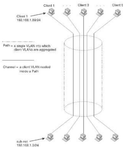
flowchart
graph TD
    A["Client 1\n192.168.1.8@24"] --> B["Path = a single VLAN into which client VLANs are aggregated"]
    C["Client 3"] --> B
    D["Client 5"] --> B
    E["sub-net\n192.168.1.0/24"] --> B
    B --> F["Channel = a client VLAN nested inside a Path"]
Each client connected to the edge device is in its own port-based VLAN, which is like an ATM channel. All the clients' VLANs are aggregated by the edge device into a single VLAN for connection to the core. The single VLAN that aggregates the clients' VLANs is like an ATM path.
The device that aggregates the VLANs forwards the aggregated VLAN traffic through the core. The core can consist of multiple devices that forward the aggregated VLAN traffic. The edge device at
FIGURE 102 Example of a super aggregated VLAN application

flowchart
graph TD
    Client1["Client 1\nPort1/1\nVLAN 101"] --> DeviceA["Device A\nTag Type 8100"]
    Client2["Client 2\nPort1/3\nVLAN 103"] --> DeviceA
    Client3["Client 3\nPort1/5\nVLAN 105"] --> DeviceA
    Client4["Client 4\nPort1/7\nVLAN 107"] --> DeviceB["Device B\nTag Type 8100"]
    Client5["Client 5\nPort1/9\nVLAN 105"] --> DeviceB
    Client6["Client 6\nPort1/1\nVLAN 101"] --> DeviceC["Device C\nTag Type 9100"]
    Client7["Client 7\nPort1/3\nVLAN 103"] --> DeviceC
    Client8["Client 8\nPort1/5\nVLAN 105"] --> DeviceC
    Client9["Client 9\nPort1/7\nVLAN 105"] --> DeviceD["Device D\nTag Type 9100"]
    Client10["Client 10\nPort1/5\nVLAN 105"] --> DeviceD
    Client11["Client 11\nPort1/7\nVLAN 103"] --> DeviceD
    Client12["Client 12\nPort1/9\nVLAN 105"] --> DeviceD
    Client13["Client 13\nPort1/7\nVLAN 103"] --> DeviceD
    Client14["Client 14\nPort1/9\nVLAN 105"] --> DeviceD
    Client15["Client 15\nPort1/7\nVLAN 103"] --> DeviceE["Device E\nTag Type 8100"]
    Client16["Client 16\nPort1/9\nVLAN 105"] --> DeviceE
    Client17["Client 17\nPort1/7\nVLAN 103"] --> DeviceE
    Client18["Client 18\nPort1/9\nVLAN 105"] --> DeviceE
    Client19["Client 19\nPort1/7\nVLAN 103"] --> DeviceE
    Client20["Client 20\nPort1/9\nVLAN 105"] --> DeviceE
    Client21["Client 21\nPort1/7\nVLAN 103"] --> DeviceE
    Client22["Client 22\nPort1/9\nVLAN 105"] --> DeviceE
    Client23["Client 23\nPort1/7\nVLAN 103"] --> DeviceE
    Client24["Client 24\nPort1/9\nVLAN 105"] --> DeviceE
    Client25["Client 25\nPort1/7\nVLAN 103"] --> DeviceE
    Client26["Client 26\nPort1/9\nVLAN 105"] --> DeviceE
    Client27["Client 27\nPort1/7\nVLAN 103"] --> DeviceE
    Client28["Client 28\nPort1/9\nVLAN 105"] --> DeviceE
    Client29["Client 29\nPort1/7\nVLAN 103"] --> DeviceE
    Client30["Client 30\nPort1/9\nVLAN 105"] --> DeviceE
    Client31["Client 31\nPort1/7\nVLAN 103"] --> DeviceE
    Client32["Client 32\nPort1/9\nVLAN 105"] --> DeviceE
    Client33["Client 33\nPort1/7\nVLAN 103"] --> DeviceE
    Client34["Client 34\nPort1/9\nVLAN 105"] --> DeviceE
    Client35["Client 35\nPort1/7\nVLAN 103"] --> DeviceE
    Client36["Client 36\nPort1/9\nVLAN 105"] --> DeviceE
    Client37["Client 37\nPort1/7\nVLAN 103"] --> DeviceE
    Client38["Client 38\nPort1/9\nVLAN 105"] --> DeviceE
    Client39["Client 39\nPort1/7\nVLAN 103"] --> DeviceE
    Client40["Client 40\nPort1/9\nVLAN 105"] --> DeviceE
Configuration notes
• Super Aggregated VLANs and VSRP are not supported together on the same device.
Configuring aggregated VLANs
To configure aggregated VLANs, perform the following tasks:
- On each edge device, configure a separate port-based VLAN for each client connected to the edge device. In each client VLAN:
- Add the port connected to the client as an untagged port.
- Add the port connected to the core device (the device that will aggregate the VLANs) as a tagged port. This port must be tagged because all the client VLANs share the port as an uplink to the core device.
- On each core device:
- Enable VLAN aggregation. This support allows the core device to add an additional tag to each Ethernet frame that contains a VLAN packet from the edge device. The additional tag identifies the aggregate VLAN (the path). However, the additional tag can cause the frame to be longer than the maximum supported frame size. The larger frame support allows Ethernet frames up to 1530 bytes long.
NOTE
Enable the VLAN aggregation option only on the core devices.
- Configure a VLAN tag type (tag ID) that is different than the tag type used on the edge devices. If you use the default tag type (8100) on the edge devices, set the tag type on the core devices to another value, such as 9100. The tag type must be the same on all the core devices. The edge devices also must have the same tag type but the type must be different from the tag type on the core devices.
NOTE
You can enable the Spanning Tree Protocol (STP) on the edge devices or the core devices, but not both. If you enable STP on the edge devices and the core devices, STP will prevent client traffic from
PowerConnect(config-vlan-104)† tagged ethernet 2/1
PowerConnect(config-vlan-104)‡ untagged ethernet 1/4
PowerConnect(config-vlan-104)‡ exit
PowerConnect(config)‡ vlan 105 by port
PowerConnect(config-vlan-105)‡ tagged ethernet 2/1
PowerConnect(config-vlan-105)‡ untagged ethernet 1/5
PowerConnect(config-vlan-105)‡ exit
PowerConnect(config)‡ write memory
Syntax: [no] vlan
Syntax: [no] tagged ethernet [
Syntax: [no] untagged ethernet [
Use the tagged command to add the port that the device uses for the uplink to the core device. Use the untagged command to add the ports connected to the individual clients.
Configuring aggregated VLANs on a core device
To configure the aggregated VLANs on device C in Figure 102 on page 479, enter the following commands.
PowerConnect(config)# tag-type 9100
PowerConnect(config)# aggregated-vlan
PowerConnect(config)# vlan 101 by port
PowerConnect(config-vlan-101)† tagged ethernet 4/1
PowerConnect(config-vlan-101)‡ untagged ethernet 3/1
PowerConnect(config-vlan-101)‡ exit
PowerConnect(config)# vlan 102 by port
PowerConnect(config-vlan 102)‡ tagged ethernet 4/1
PowerConnect(config-vlan-102)‡ untagged ethernet 3/2
PowerConnect(config-vlan-102)‡ exit
PowerConnect(config)# write memory
Syntax: [no] tag-type
Syntax: [no] aggregated-vlan
NOTE
In these examples, the configurations of the edge devices (A, B, E, and F) are identical. The configurations of the core devices (C and D) also are identical. The aggregated VLAN configurations of the edge and core devices on one side must be symmetrical (in fact, a mirror image) to the configurations of the devices on the other side. For simplicity, the example in Figure 102 on page 479 is symmetrical in terms of the port numbers. This allows the configurations for both sides of the link to be the same. If your configuration does not use symmetrically arranged port numbers, the configurations should not be identical but must use the correct port numbers.
Commands for device A
PowerConnectA(config)# vlan 101 by port PowerConnectA(config-vlan-101)# tagged ethernet 2/1 PowerConnectA(config-vlan-101)# untagged ethernet 1/1 PowerConnectA(config-vlan-101)# exit PowerConnectA(config)# vlan 102 by port PowerConnectA(config-vlan-102)# Lagged ethernet 2/1 PowerConnectA(config-vlan-102)# untagged ethernet 1/2 PowerConnectA(config-vlan-102)# exit PowerConnectA(config)# vlan 103 by port PowerConnectA(config-vlan-103)# tagged ethernet 2/1 PowerConnectA(config-vlan-103)# untagged ethernet 1/3 PowerConnectA(config-vlan-103)# exit PowerConnectA(config)# vlan 104 by port PowerConnectA(config-vlan-104)# tagged ethernet 2/1 PowerConnectA(config-vlan-104)# untagged ethernet 1/4 PowerConnectA(config-vlan-104)# exit PowerConnectA(config)# vlan 105 by port PowerConnectA(config-vlan-105)# Lagged ethernet 2/1 PowerConnectA(config-vlan-105)# untagged ethernet 1/5 PowerConnectA(config-vlan-105)# exit PowerConnectA(config)# write memory
Commands for device B
The commands for configuring device B are identical to the commands for configuring device A.
PowerConnectB(config)↑ vlan 105 by port
PowerConnectB(config-vlan-105)# tagged ethernet 2/1
PowerConnectB (config-vlan-105) ≠ untagged ethernet 1/5
PowerConnectB(config-vlan-105)# exit
PowerConnectB(config) # write memory
Commands for device C
Because device C is aggregating channel VLANs from devices A and B into a single path, you need to change the tag type and enable VLAN aggregation.
PowerConnectC (config) # tag-type 9100
PowerConnectC(config)↑ aggregated-vlan
PowerConnectC(config)† vlan 101 by port
PowerConnectC(config-vlan-101)‡ lagged ethernet 4/1
PowerConnectC(config-vlan-101)# untagged ethernet 3/1
PowerConnectC(config-vlan-101)# exit
PowerConnectC(config) ↕ vlan 102 by port
PowerConnectC(config-vlan-102)# tagged ethernet 4/1
PowerConnectC (config-vlan-102) ‡ untagged ethernet 3/2
PowerConnectC(config-vlan-102)# exit
PowerConnectC(config) # write memory
Commands for device D
Device D is at the other end of path and separates the channels back into individual VLANs. The tag type must be the same as tag type configured on the other core device (Device C). In addition, VLAN aggregation also must be enabled.
PowerConnectD(config)# tag-type 9100
PowerConnectD (config) ‡ aggregated-vlan
PowerConnectD(config)† vlan 101 by port
PowerConnectD(config vlan 101)# tagged ethernet 4/1
PowerConnectD(config-vlan-101)# untagged ethernet 3/1
PowerConnectD (config-vlan-101) # exit
PowerConnectD (config) 4 vlan 102 by port
PowerConnectD(config-vlan-102)# tagged ethernet 4/1
PowerConnectD(config-vlan-102)# untagged ethernet 3/2
PowerConnectE(config)↑ vlan 104 by port
PowerConnectE(config-vlan-104)# tagged ethernet 2/1
PowerConnectE (config-vlan-104) ‡ untagged ethernet 1/4
PowerConnectE(config-vlan-104)# exit
PowerConnectE(config)‡ vlan 105 by port
PowerConnect8(config-vlan-105)# tagged ethernet 2/1
PowerConnectE(config-vlan-105)# untagged ethernet 1/5
PowerConnectE (config-vlan-105) # exit
PowerConnectE(config)† write memory
Commands for device F
The commands for configuring device F are identical to the commands for configuring device E. In this example, Because the port numbers on each side of the configuration in Figure 102 on page 479 are symmetrical, the configuration of device F is also identical to the configuration of device A and device B.
PowerConnectF(config)‡ vlan 101 by port
PowerConnectF(config-vlan-101)# tagged ethernet 2/1
PowerConnectF(config-vlan-101)# untagged ethernet 1/1
PowerConnectF(config-vlan-101) # exit
PowerConnectF(config)† vlan 102 by port
PowerConnectF (config-vlan-102) ‡ Lagged ethernet 2/1
PowerConnectF(config-vlan-102)# untagged ethernet 1/2
PowerConnectF (config-vlan-102)# exit
PowerConnectF(config) +/- vlan 103 by port
PowerConnectF(config-vlan-103)# tagged ethernet 2/1
PowerConnectF (config-vlan-103) ≠ untagged ethernet 1/3
PowerConnectF(config-vlan-103)# exit
PowerConnectF(config)# vlan 104 by port
PowerConnectE(config-vlan-104)# tagged ethernet 2/1
PowerConnectF(config-vlan-104)# untagged ethernet 1/4
PowerConnectF (epl[io-v]an-104) # exit
PowerConnectF(config)↑ vlan 105 by port
PowerConnectF (config-vlan-105)# tagged ethernet 2/1
PowerConnectF(config-vlan-105)# untagged ethernet 1/5
PowerConnectF (config-vlan-105)# exit
PowerConnectF(config) + write memory
FIGURE 103 802.1Q-in-Q configuration example

flowchart
graph TD
    A["Provider Edge Switch"] -->|Untagged| B["Configured tag-type 9100"]
    A -->|Tagged| C["Default tag-type 8100"]
    D["To customer interface"] --> A
    E["Uplink to provider cloud"] --> A
| DA | SA | 8100 | Customer VLAN |
| DA | SA | 8100 | 8100 | ProviderVLAN | CustomerVLAN |
In Figure 103, the untagged ports (to customer interfaces) accept frames that have any 802.1Q tag other than the configured tag-type 9100. These packets are considered untagged on this incoming port and are re-tagged when they are sent out of the uplink towards the provider. The 802.1Q tag-type on the uplink port is 8100, so the Dell PowerConnect device will switch the frames to the uplink device with an additional 8100 tag, thereby supporting devices that only support this method of VLAN tagging.
Configuration rules
- Because the uplink (to the provider cloud) and the edge link (to the customer port) must have different 802.1Q tags, make sure the uplink and edge link are in different port regions. Refer to "About port regions" on page 306 for a list of valid port regions.
- On devices that support port regions, if you configure a port with an 802.1Q tag-type, the Dell
PowerConnect(config)# tag-type 9100 ethernet 11 to 12
PowerConnect {config} # aggregated-vlan
Note that because ports 11 and 12 belong to the port region 1 - 12, the 802.1Q tag actually
applies to ports 1 - 12.
Syntax: [no] tag-type
Specify the
• PowerConnect B-Series FCX stackable switches -
The ethernet
This parameter operates with the following rules:
- If you specify a single port number, the 802.1Q tag applies to all ports within the port region. For example, if you enter the command tag-type 9100 ethernet 1, the Dell PowerConnect device automatically applies the 802.1Q tag to ports 1 - 12 because all of these ports are in the same port region. You can use the show running-config command to view how the command has been applied.
- If you do not specify a port or range of ports, the 802.1Q tag applies to all Ethernet ports on the device.
Example configuration
Figure 104 shows an example 802.1Q-in-Q configuration.
FIGURE 104 Example 802.1Q-In-Q configuration

flowchart
graph TD
    Client1["Client 1 Port1 VLAN 101"] -->|9100 Untagged| DeviceA["Device A"]
    Client2["Client 1 192.168.1.69/24"] -->|9100 Untagged| DeviceA
    Client3["Client 3 Port3 VLAN 103"] -->|9100 Untagged| DeviceA
    Client4["Client 5 Port5 VLAN 105"] -->|9100 Untagged| DeviceA
    Client5["Client 5 209.157.2.12/24"] -->|9100 Untagged| DeviceA
    Client6["Client 8 Port1 VLAN 101"] -->|9100 Untagged| DeviceB["Device B"]
    Client7["Client 8 Port3 VLAN 103"] -->|9100 Untagged| DeviceB
    Client8["Client 10 Port5 VLAN 105"] -->|9100 Untagged| DeviceB
    Client9["Port 1-5 Untagged"] --> DeviceC["Device C"]
    Client10["Port 1-5 Untagged"] --> DeviceC
    DeviceA -->|9100 Tagged| DeviceC
    DeviceB -->|9100 Tagged| DeviceC
    DeviceC -->|9100 Tagged| DeviceD["Device D"]
    DeviceC -->|8100 Tag Type 9100 on ports 11 and 12| DeviceD
    DeviceC -->|8100 Tag Type 9100 on ports 11 and 12| DeviceD
    DeviceD -->|9100 Tag Type 9100 on ports 11 and 12| DeviceD
    DeviceD -->|9100 Tag Type 9100 on ports 11 and 12| DeviceD
    DeviceC -->|8100 Tag Type 9100 on ports 11 and 12| DeviceD
Configuring 802.1Q-in-Q tag profiles
The 802.1Q-in-Q tagging feature supports a tag-profile command that allows you to add a tag profile with a value of 0 to 0xffff in addition to the default tag-type 0x8100. This enhancement also allows you to add a tag profile for a single port, or to direct a group of ports to a globally-configured tag profile.
Configuration notes
- One global tag profile with a number between 0 and 0xffff can be configured on stackable devices.
- On individual ports, if tag-profile is enabled, it points to the global tag profile.
• Tag-profile can also be enabled for provisional ports. - Tag-type and tag-profile cannot be configured at the same time. You will see the message "un-configure the tag-type to set the tag-profile." It tag-type is already configured, you will need to unconfigure it and then add the tag-profile.
- Do not use the tag-type command in conjunction with the tag-profile command. If a tag-type has already been configured and you try to use the tag-profile command, you will see an error message telling you to remove the tag-type before you add the tag-profile.
- For devices operating in an IronStack topology, when a tag-type for a port is changed, the tag-type for all of the ports on a stack unit also changes. Because of this limitation, SAV and Q-in-Q cannot be used at the same time on stacking devices.
CLI Syntax
To add a global tag-profile enter the following command.
PowerConnect{config}# tag-profile 9500
This command adds a profile in addition to the default profile of 0x8100.
Syntax: [no] tag-profile
where
FIGURE 105 PVLAN used to secure communication between a workstation and servers
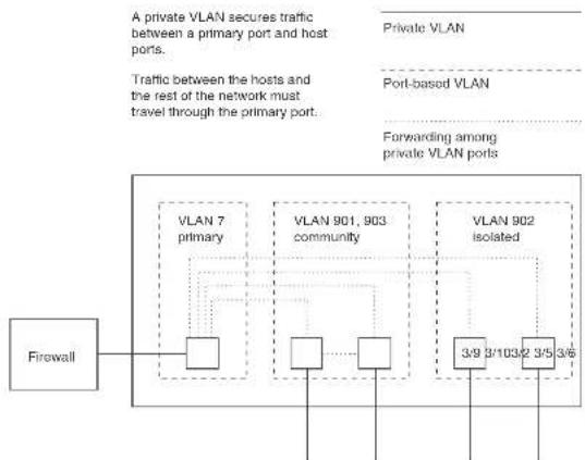
flowchart
graph TD
    A["Firewall"] --> B["VLAN 7 primary"]
    A --> C["VLAN 901, 903 community"]
    A --> D["VLAN 902 isolated"]
    B --> E["Port-based VLAN"]
    C --> F["Port-based VLAN"]
    D --> G["Port-based VLAN"]
    style A fill:#f9f,stroke:#333
    style B fill:#ccf,stroke:#333
    style C fill:#ccf,stroke:#333
    style D fill:#ccf,stroke:#333
This example uses a PVLAN to secure traffic between hosts and the rest of the network through a firewall. Five ports in this example are members of a PVLAN. The first port (port 3/2) is attached to a firewall. The next four ports (ports 3/5, 3/6, 3/9, and 3/10) are attached to hosts that rely on the firewall to secure traffic between the hosts and the rest of the network. In this example, two of the hosts (on ports 3/5 and 3/6) are in a community PVLAN, and thus can communicate with one
- Community – Broadcasts and unknown unicasts received on community ports are sent to the primary port and also are flooded to the other ports in the community VLAN.
Each PVLAN must have a primary VLAN. The primary VLAN is the interface between the secured ports and the rest of the network. The PVLAN can have any combination of community and isolated VLANs.
As with regular VLANs, PVLANs can span multiple switches. The PVLAN is treated like any other VLAN by the PVLAN-trunk ports. The PVLAN-trunk port is added to both the primary and the secondary VLANs as a tagged member through the pvlan-trunk command. Figure 106 shows an example of a PVLAN network across switches:
- Broadcast, unknown unicast or unregistered multicast traffic from the primary VLAN port is forwarded to all ports in isolated and community VLANs in both the switches.
- Broadcast, unknown unicast or unregistered multicast traffic from an isolated port in switch A is not forwarded to an isolated port in switch A. It will not be forwarded to an isolated port in switch B across the PVLAN-trunk port.
- Broadcast, unknown unicast or unregistered multicast traffic from a community port in switch A will be forwarded to a community port in switch B through the PVLAN-trunk port. It is forwarded to the promiscuous ports and switch – switch ports of the primary VLAN.
FIGURE 106 PVLAN across switches
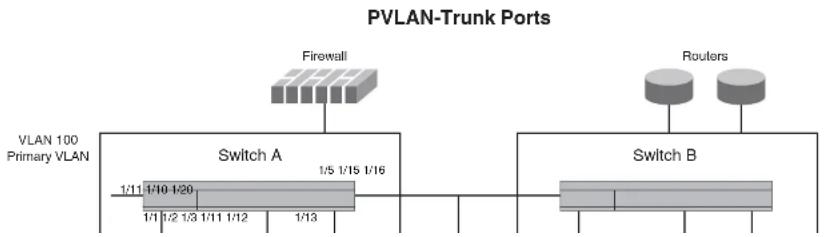
flowchart
graph TD
    A["VLAN 100 Primary VLAN"] --> B["Switch A"]
    B --> C["1/11 1/10 1/20"]
    B --> D["1/1 1/2 1/3 1/11 1/12"]
    B --> E["1/13"]
    F["Firewall"] --> G["Switch B"]
    H["Routers"] --> I["Switch B"]
    style A fill:#f9f,stroke:#333
    style B fill:#ccf,stroke:#333
    style C fill:#cfc,stroke:#333
    style D fill:#fcc,stroke:#333
    style E fill:#cff,stroke:#333
    style F fill:#ffc,stroke:#333
    style G fill:#cfc,stroke:#333
    style H fill:#fcc,stroke:#333
FIGURE 107 Example PVLAN network with tagged ports

flowchart
graph TD
    A["VLAN 100 Promiscuous Ports"] -->|4| B["Switch 1 Switch 2"]
    B -->|10 10| C["Switch 3"]
    C -->|11| D["Switch 4"]
    D -->|10 10| E["Switch 1"]
    style A fill:#f9f,stroke:#333
    style B fill:#ccf,stroke:#333
    style C fill:#cfc,stroke:#333
    style D fill:#fcc,stroke:#333
    style E fill:#cff,stroke:#333
VLAN 100 - switch - switch link Ports
Table 79 lists the differences between PVLANs and standard VLANs.
TABLE 79 Comparison of PVLANs and standard port-based VLANs
PowerConnect device will flood unknown unicast, unregistered multicast, and broadcast packets in software. The flooding of broadcast or unknown unicast from the community or isolated VLANs to other secondary VLANs will be governed by the PVLAN forwarding rules. The switching is done in hardware and thus the CPU does not enforce packet restrictions. The hardware forwarding behavior is supported on the PowerConnect B-Series FCX platforms only.
- There is currently no support for IGMP snooping within PVLANs. In order for clients in PVLANs to receive multicast traffic, IGMP snooping must be disabled so that all multicast packets are treated as unregistered packets and are flooded in software to all the ports.
- The PowerConnect forwards all known unicast traffic in hardware. This differs from the way the BigIron implements PVLANs, in that the BigIron uses the CPU to forward packets on the primary VLAN "promiscuous" port. In addition, on the BigIron, support for the hardware forwarding sometimes results in multiple MAC address entries for the same MAC address in the device MAC address table. On the PowerConnect, multiple MAC entries do not appear in the MAC address table because the PowerConnect transparently manages multiple MAC entries in hardware.
- To configure a PVLAN, configure each of the component VLANs (isolated, community, and public) as a separate port based VLAN:
- Use standard VLAN configuration commands to create the VLAN and add ports.
- Identify the PVLAN type (isolated, community, or public)
- For the primary VLAN, map the other PVLANs to the ports in the primary VLAN
- A primary VLAN can have multiple ports. All these ports are active, but the ports that will be used depends on the PVLAN mappings. Also, secondary VLANs (isolated and community VLANs) can be mapped to multiple primary VLAN ports.
- You can configure PVLANs and dual-mode VLAN ports on the same device. However, the dual-mode VLAN ports cannot be members of PVLANs.
- VLAN identifiers configured as part of a PVLAN (primary, isolated, or community) should be consistent across the switched network. The same VLAN identifiers cannot be configured as a normal VLAN or a part of any other PVLAN.
- Promiscuous and switch-switch link ports are member ports of the primary VLAN only. All switch-switch link ports are tagged ports.
• Member ports of isolated and community VLANs cannot be member ports of any other VLAN.
To map the secondary VLANs to the primary VLAN and to configure the tagged switch link port, enter commands such as the following.
PowerConnect(config)# vlan 100
PowerConnect(config-vlan-100)† tagged ethernet 1/1/10 to 1/1/11
PowerConnect(config-vlan-100)↓ untagged ethernet 1/1/4
PowerConnect(config-vlan-100)↓ pvlan type primary
PowerConnect(config-vlan-100)# pvlan mapping 101 ethernet 1/1/4
PowerConnect(config-vlan-100)↓ pvlan mapping 102 ethernet 1/1/4
PowerConnect(config-vlan-100)† pvlan pvlan-trunk 101 ethernet 1/1/10 to 1/1/11
These commands create port-based VLAN 100, add port 1/1/10 to 1/1/11 as a tagged port, identify the VLAN as the primary VLAN in a PVLAN, map the other secondary VLANs to the ports in this VLAN, and configure the tagged switch link port.
Syntax: untagged ethernet [
[
or
Syntax: tagged ethernet [
[
Syntax: [no] pvlan type community | isolated | primary
Syntax: [no] pvlan mapping
Syntax: [no] pvlan pvlan-trunk
The untagged or tagged command adds the ports to the VLAN.
The pvlan type command specifies that this port-based VLAN is a PVLAN. Specify primary as the type.
The pvlan mapping command identifies the other PVLANs for which this VLAN is the primary. The command also specifies the primary VLAN ports to which you are mapping the other secondary VLANs. The mapping command is not allowed on the secondary VLANs. The parameters of the pvlan mapping command are as follows:
- The
- An isolated VLAN must be associated with the primary VLAN for traffic from the isolated port to be switched. An isolated VLAN is associated with only one primary VLAN and to the same primary VLAN in the entire switched network.
- An isolated port communicates only with the configured switch-switch link port if there are no promiscuous ports configured for the isolated VLAN.
- A primary VLAN is associated with only one isolated VLAN. An isolated VLAN can only be mapped to a promiscuous port and a switch-switch link port that belong to the same primary VLAN.
- Link Aggregation Group (LAG) ports are not allowed as member ports of an isolated VLAN.
Community VLANs
- A port being added to the community VLAN can be either a tagged port or an untagged port.
• A member port of a community VLAN classifies a frame based on PVID only. - A community VLAN is associated with only one primary VLAN and to the same primary VLAN in the entire switched network. A primary VLAN is associated with multiple community VLANs.
- A community VLAN must be associated with the primary VLAN for traffic from the community port to be switched.
• LAG ports are not allowed as member ports of a community VLAN.
To configure a community PVLAN, enter commands such as the following.
PowerConnect(config)# vlan 901
PowerConnect(config-vlan-901)‡ untagged ethernet. 3/5 to 3/6
PowerConnect(config-vlan-501)† pvlan type community
These commands create port-based VLAN 901, add ports 3/5 and 3/6 to the VLAN as untagged ports, then specify that the VLAN is a community PVLAN.
Syntax: untagged ethernet [
or
Syntax: tagged ethernet [
Enabling broadcast or unknown unicast traffic to the PVLAN
To enhance PVLAN security, the primary PVLAN does not forward broadcast or unknown unicast packets to its community and isolated VLANs, and other ports in the primary VLAN. For example, if port 3/2 in Figure 105 on page 489 receives a broadcast packet from the firewall, the port does not forward the packet to the other PVLAN ports (3/5, 3/6, 3/9, and 3/10).
This forwarding restriction does not apply to traffic from the PVLAN. The primary port does forward broadcast and unknown unicast packets that are received from the isolated and community VLANs. For example, if the host on port 3/9 sends an unknown unicast packet, port 3/2 forwards the packet to the firewall.
If you want to remove the forwarding restriction, you can enable the primary port to forward broadcast or unknown unicast traffic, if desired, using the following CLI method. You can enable or disable forwarding of broadcast or unknown unicast packets separately.
NOTE
On Layer 2 Switches and Layer 3 Switches, you also can use MAC address filters to control the traffic forwarded into and out of the PVLAN. In addition, if you are using a Layer 2 Switch, you also can use ACLs.
NOTE
PowerConnect B-Series FCX devices do not support ACLs on interface groups.
Command syntax
To configure the ports in the primary VLAN to forward broadcast or unknown unicast and multicast traffic received from sources outside the PVLAN, enter the following commands at the global CONFIG level of the CLI.
PowerConnect(config)† pvlan-preference broadcast flood PowerConnect(config)† pvlan-preference unknown-unicast flood
These commands enable forwarding of broadcast and unknown-unicast packets to ports within the
CLI example for a general PVLAN network
To configure the PVLANs shown in Figure 105 on page 489, enter the following commands.
PowerConnect(config)# vlan 901
PowerConnect(config-vlan-901)† untagged ethernet 3/5 to 3/6
PowerConnect(config-vlan-901)‡ pvlan type community
PowerConnect(config-vlan-901) exit
PowerConnect{config}# vlan 902
PowerConnect(config-vlan-902)↓ unlagged ethernet. 3/9 to 3/10
PowerConnect(config-vlan-902)† pvlan type isolated
PowerConnect(config-vlan-902) # exit
PowerConnect(config)# vlan 903
PowerConnect(config-vlan-503)† untagged ethernet 3/7 to 3/8
PowerConnect(config-vlan-903)◆ pvlan type community
PowerConnect(config-vlan-903)† exit
PowerConnect(config) ± vlan 7
PowerConnect(config-vlan-7)# untagged ethernet 3/2
PowerConnect(config-vlan-7)# pvlan type primary
PowerConnect(config-vlan-7)# pvlan mapping 901 ethernet 3/2
PowerConnect(config-vlan-7)# pvlan mapping 902 ethernet 3/2
PowerConnect(config-vlan-7)# pvlan mapping 903 ethernet 3/2
CLI example for a PVLAN network with switch-switch link ports
To configure the PVLANs with tagged switch-switch link ports as shown in Figure 107 on page 491, enter the following commands.
PowerConnect B-Series FCX Switch 1
PowerConnect{config}# vlan 101 by port
PowerConnect(config-vlan-101)↓ untagged ethernet 1/1/3
PowerConnect(config-vlan-101)† pvlan type isolated
PowerConnect(config)# vlan 102 by port
PowerConnect(config-vlan-102)‡ untadded ethernet 1/1/1 to 1/1/2
PowerConnect(config)# vlan 100 by port
PowerConnect(config-vlan-100)† tagged ethernet 1/1/10 to 1/1/11
PowerConnect(config-vlan-100)‡ pvlan type primary
PowerConnect(config-vlan-100)↑ pvlan pvlan-trunk 102 ethernet 1/1/10 to 1/1/11
PowerConnect(config-vlan-100)‡ pvlan pvlan-trunk 101 ethernet 1/1/10 to 1/1/11
PowerConnect B-Series FCX 3
PowerConnect(config)# vlan 101 by port
PowerConnect(config-vlan-101)↑ untagged ethernet. 1/1/3
PowerConnect(config-vlan-101)# pvlan type isolated
PowerConnect(config)# vlan 102 by port
PowerConnect(config-vlan-102)≠ untagged ethernet 1/1/1 to 1/1/2
PowerConnect(config-vlan-102)↑ pvlan type community
PowerConnect(config)# vlan 100 by port
PowerConnect(config-vlan-100)† tagged ethernet 1/1/10 to 1/1/11
PowerConnect(config-vlan-100)‡ pvlan type primary
PowerConnect(config-vlan-100)◆ pvlan pvlan-trunk 102 ethernet 1/1/10 to 1/1/11
PowerConnect(config-vlan-100)‡ pvlan pvlan-trunk 101 ethernet 1/1/10 to 1/1/11
PowerConnect B-Series FCX 4
PowerConnect(config)# vlan 101 by port
PowerConnect(config-vlan-101)‡ untagged ethernet 1/1/3
PowerConnect(config-vlan-101)† pvlan type isolated
PowerConnect(config)# vlan 102 by port
PowerConnect(config-vlan-102)† untagged ethernet 1/1/1 to 1/1/2
PowerConnect(config-vlan-102) + pvlan type communi
PowerConnect(config)# vlan 100 by port
PowerConnect(config-vlan-100)‡ tagged ethernet 1/1/10 to 1/1/11
PowerConnect(config-vlan-100)‡ pvlan type primary
PowerConnect(config-vlan-100)‡ pvlan pvlan-trunk 102 ethernet 1/1/10 to 1/1/11
PowerConnect(config-vlan-100)‡ pvlan pvlan-trunk 101 ethernet 1/1/10 to 1/1/11
FIGURE 108 Dual-mode VLAN port example
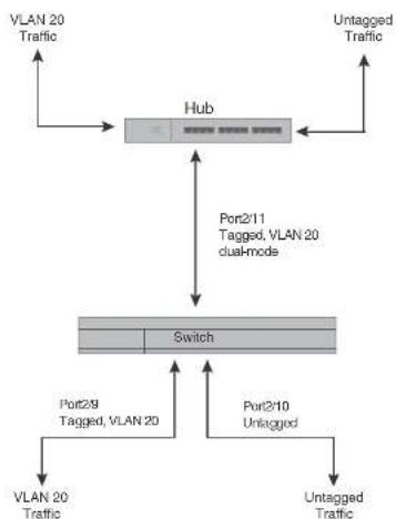
flowchart
graph TD
    A["VLAN 20 Traffic"] --> B["Hub"]
    C["Untagged Traffic"] --> B
    B --> D["Port2/11 Tagged, VLAN 20 dual-mode"]
    D --> E["Switch"]
    F["VLAN 20 Traffic"] --> E
    G["Port2/9 Tagged, VLAN 20"] --> E
    H["Port2/10 Untagged"] --> E
    E --> I["Untagged Traffic"]
    J["VLAN 20 Traffic"] --> K["Untagged Traffic"]
To enable the dual-mode feature on port 2/11 in Figure 108, enter the following commands.
PowerConnect(config)# vlan 20
PowerConnect(config-vlan-20)# tagged ethernet 2/11
PowerConnect(config-vlan-20)# tagged ethernet 2/8
PowerConnect(config-vlan-20)# interface ethernet 2/11
PowerConnect(config-if-e1000-2/11)# dual-mode
PowerConnect(config-if-e1000-2/11)# exit
FIGURE 109 Specifying a default VLAN ID for a dual-mode port

flowchart
graph TD
    A["Hub"] --> B["Switch"]
    B --> C["VLAN 10 Untagged Traffic"]
    B --> D["VLAN 20 Untagged Traffic"]
    B --> E["VLAN 20 Tagged Traffic"]
    B --> F["Dual-mode Port2/11 Default VLAN ID 10 Tagged, VLAN 20"]
    F --> G["VLAN 10 Untagged Traffic"]
    F --> H["VLAN 20 Tagged Traffic"]
    F --> I["Port2/10 Untagged, VLAN 10"]
    I --> J["VLAN 10 Untagged Traffic"]
    I --> K["VLAN 20 Tagged Traffic"]
    K --> L["VLAN 20 Tagged Traffic"]
    style A fill:#f9f,stroke:#333
    style B fill:#ccf,stroke:#333
    style C fill:#cfc,stroke:#333
    style D fill:#fcc,stroke:#333
    style E fill:#cff,stroke:#333
    style F fill:#ffc,stroke:#333
    style G fill:#fcc,stroke:#333
    style H fill:#cff,stroke:#333
    style I fill:#fcc,stroke:#333
    style J fill:#fcc,stroke:#333
    style K fill:#fcc,stroke:#333
    style L fill:#fcc,stroke:#333
In Figure 109, tagged port 2/11 is a dual-mode port belonging to VLANs 10 and 20. The default VLAN assigned to this dual-mode port is 10. This means that the port transmits tagged traffic on VLAN 20 (and all other VLANs to which the port belongs) and transmits untagged traffic on VLAN 10.
The dual-mode feature allows tagged traffic for VLAN 20 and untagged traffic for VLAN 10 to go through port 2/11 at the same time. A dual-mode port transmits only untagged traffic on its default VLAN (that is, either VLAN 1, or a user-specified VLAN ID), and only tagged traffic on all other VLANs.
The following commands configure VLANs 10 and 20 in Figure 109. Tagged port 2/11 is added to VLANs 10 and 20, then designated a dual-mode port whose specified default VLAN is 10. In this configuration, port 2/11 transmits only untagged traffic on VLAN 10 and only tagged traffic on VLAN 20.
PowerConnect(config)# vlan 10 by port PowerConnect(config=1014 unbranded ethernet 2/10
The show vlan command displays a separate row for dual-mode ports on each VLAN.
Example
PowerConnect↓ show vlan
Total PORT-VLAN entries: 3
Maximum PORT-VLAN entries: 16
legend: [S-Slot]
PORT-VLAN 1, Name DEFAULT-VLAN, Priority level0, Spanning tree Off
Untagged Ports: (S1) 1 2 3 4 5 6 7 8
Untagged Ports: (S2) 1 2 3 4 5 6 7 8 12 13 14 15 16 17 18 19
Untagged Ports: (S3) 20 21 22 23 24
Tagged Ports: None
DualMode Ports: None
PORT-VLAN 10, Name [None], Priority level0, Spanning tree Off
Untagged Ports: (S2) 10
Tagged Ports: None
Uplink Ports: None
DualMode Ports: (S2) 11
PORT-VLAN 20, Name [None], Priority level0, Spanning tree Off
Untagged Ports: None
Tagged Ports: (S2) 9
Uplink Ports: None
DualMode Ports: (S2) 11
Displaying VLAN information
After you configure the VLANs, you can verify the configuration using the show commands described in this section.
NOTE
If a VLAN name begins with "GVRP_VLAN_", the VLAN was created by the GARP VLAN Registration
Displaying system-wide VLAN information
Use the show vlans command to display VLAN information for all the VLANs configured on the
device.
The following example shows the display for the IP subnet and IPX network VLANs configured in the examples in "Configuring an IP subnet VLAN with dynamic ports" on page 466 and "Configuring an IPX network VLAN with dynamic ports" on page 467.
PowerConnect# show vians
Total PORT-VLAN entries: 2
Maximum PORT-VLAN entries: 8
legend: [S=Slot]
PORT-VLAN 1, Name DEFAULT-VLAN, Priority level0, Spanning tree Off
Untagged Ports: (92) 1 2 3 4 5 6 7 8 9 10 11 12 13 14 15 16
Untagged Ports: (S2) 17 18 19 20 21 22 23 24
Untagged Ports: (24) 1 2 3 4 5 6 7 8 9 10 11 12 13 14 15 16
Untagged Ports: (S4) 17 18 19 20 21 22 23 24
Tagged Ports: None
PORT-VLAN 10, Name IP_VLAN, Priority level0, Spanning tree Off
Untagged Ports: (91) 1 2 3 4 5 6
Tagged Ports: None
IP-subnet.VLAN 1.1.1.0 255.255.255.0, Dynamic port enabled
Name: Mktg-LAN
Static ports: None
Exclude ports: None
Dynamic ports: {51} 1 2 3 4 5 6
PORT-VLAN 20, Name IPX_VLAN, Priority level0, Spanning tree off
Untagged Ports: (S2) 1 2 3 4 5 6
Tagged Ports: None
IPX-network VLAN 0000ABCD, frame type ethernet_ii, Dynamic port enabled
Name: Eng-LAN
Static ports: None
Exclude ports: None
Boseli et al., 1991, 1, 9, 9, 4, 5, 6
PowerConnect# show vlan 4
Total PORT-VLAN entries: 5
Maximum PORT-VLAN entries: 3210
PORT-VLAN 4, Name [None], Priority level0, Spanning tree off
Untagged Ports: None
Tagged Ports: 6 9 10 11
Uplink Ports: None
DualKode Ports: 7 8
PowerConnect# show vlan 3
Total PORT-VLAN entries: 5
Maximum PORT-VLAN entries: 3210
PORT-VLAN 3, Name [None], Priority level0, Spanning tree off
Untagged Ports: None
Tagged Ports: 6 7 8 9 10
Uplink Ports: None
DualKode Ports: None
Syntax: show vlans [
The
The
The
Displaying global VLAN information
The show vlan brief command displays the following information:
• The system-max VLAN values (maximum, default, and current)
• The default VLAN ID number
• The total number of VLANs configured on the device
• The VLAN ID numbers of the VLANs configured on the device
The following shows example output.
PowerConnect# show vians ethernet 7/1
Total PORT-VLAN entries: 3
Maximum PORT-VLAN entries: 8
legend: [S=Slot]
PORT-VLAN 100, Name [None], Priority level 10, Spanning tree Off
Untagged Ports: (S7) 1 2 3 4
Tagged Ports: None
Syntax: show vlans [
The
The
The
Displaying a port VLAN membership
To display VLAN membership for a specific port on the device, enter a command such as the following.
PowerConnect# show vlan brief ethernet 7
Port 7 is a member of 3 VLANs
VLANs 3 to 4 10
Syntax: show vlan brief ethernet [
The
Displaying a port dual-mode VLAN membership
The output of the show interfaces command lists dual-mode configuration and corresponding VLAN
- For untagged ports, the PVID is the VLAN ID number.
• For dual-mode ports, the PVID is the dual-mode VLAN ID number. - For tagged ports without dual-mode, the PVID is always Not Applicable (NA).
PowerConnect# show interfaces brief
| Port | Link | State | Dup1 | Speed | Trunk | Tag | Pvid | Pri | MAC | Name |
| 1 | Up | Forward | Full | 1G | None | No | 1 | 0 | 0012.f2a8.4700 | a12345678901 |
| 2 | Up | Forward | Full | 1G | None | Yes | 1 | 0 | 0012.f2a8.4701 | |
| 3 | Up | Forward | Full | 1G | None | Yes | NA | 0 | 0012.f2a8.4702 | |
| 4 | Up | Forward | Full | 1G | None | Yes | NA | 0 | 0012.f2a8.4703 | |
| 5 | Up | Forward | Full | 1G | None | No | 2 | 0 | 0012.f2a8.4704 | |
| 6 | Down | None | None | None | None | Yes | NA | 0 | 0012.f2a8.4705 | |
| 7 | Down | None | None | None | None | Yes | 4 | 0 | 0012.f2a8.4706 | |
| 8 | Down | None | None | None | None | Yes | 4 | 0 | 0012.f2a8.4707 | |
| 9 | Down | None | None | None | None | Yes | NA | 0 | 0012.f2a8.4708 | |
| 10 | Down | None | None | None | None | Yes | NA | 0 | 0012.f2a8.4709 |
Syntax: show interfaces brief [ethernet [
The
Displaying PVLAN information
To display the PVLAN configuration with respect to the primary VLAN and its associated secondary VLANs and to display the member ports, promiscous ports, and the switch-switch link ports of a PVLAN, enter a command such as the following.
PowerConnect# show pvlan
PVLAN: primary VLAN 100
Port 1/1/4 1/1/10 1/1/11
Community VLAN 102
Port 1/1/1 1/1/2 1/1/10 1/1/11
Promiscuous Port: 1/1/4
Inter switch link Port: 1/1/10 1/1/11
SpdnGuard enabled Port: 1/1/1 1/1/2
Configuring GARP VLAN Registration Protocol (GVRP)
Chapter
Table 81 lists the individual Dell PowerConnect switches and the GVRP features they support.
TABLE 81 Supported GVRP features
| Feature PowerConnect B-Series FCX | |
| GVRP | Yes |
| Configurable GVRP base VLAN ID | Yes |
| Leaveall timer | Yes |
| Ability to disable VLAN advertising | Yes |
| Ability to disable VLAN learning | Yes |
| GVRP timers | Yes |
| Conversion of a GVRP VLAN to a statically configured VLAN | Yes |
GVRP overview
GARP VLAN Registration Protocol (GVRP) is a Generic Attribute Registration Protocol (GARP) application that provides VLAN registration service by means of dynamic configuration (registration) and distribution of VLAN membership information.
A Dell PowerConnect device enabled for GVRP can do the following:
- Learn about VLANs from other Dell PowerConnect devices and configure those VLANs on the ports that learn about the VLANs. The device listens for GVRP Protocol Data Units (PDUs) from
• IEEE draft P802.1t/D10, November 20, 2000
Application examples
Figure 110 shows an example of a network that uses GVRP. This section describes various ways you can use GVRP in a network such as this one. "CLI examples" on page 522 lists the CLI commands to implement the applications of GVRP described in this section.
FIGURE 110 Example of GVRP
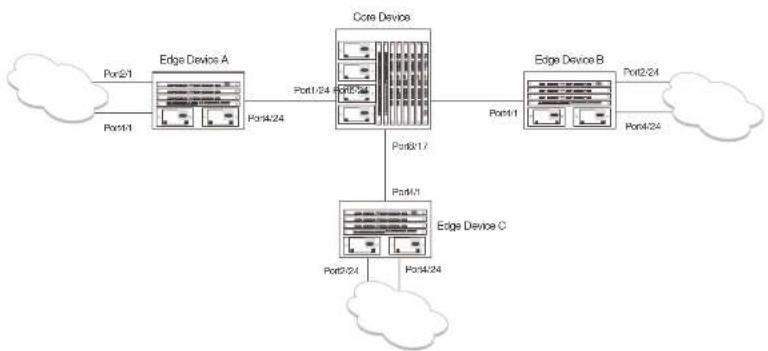
flowchart
graph TD
    A["Edge Device A"] -->|Port1-24 Port2-24| B["Core Device"]
    B -->|Port3-17| C["Edge Device B"]
    C -->|Port2-24 Port4-24| D["Edge Device C"]
    D -->|Port2-24 Port4-24| E["Cloud"]
    A -->|Port2-1| F["Cloud"]
    B -->|Port1-1 Port2-1| G["Cloud"]
In this example, a core device is attached to three edge devices. Each of the edge devices is attached to other edge devices or host stations (represented by the clouds).
The effects of GVRP in this network depend on which devices the feature is enabled on, and whether both learning and advertising are enabled. In this type of network (a core device and edge
Core device Edge device A Edge device B Edge device C
| GVRP is enabled on all ports.Both learning and advertising are enabled.NOTE: Since learning is disabled on all the edge devices, advertising on the core device has no effect in this configuration. | GVRP is enabled on port 4/24. Learning is disabled.VLAN 20Port 2/1 (untagged)Port 4/24 (tagged)VLAN 40Port 4/1 (untagged)Port 4/24 (tagged) | GVRP is enabled on port 4/1. Learning is disabled.VLAN 20Port 2/24 (untagged)Port 4/1 (tagged)VLAN 30Port 4/24 (untagged)Port 4/1 (tagged) | GVRP is enabled on port 4/1. Learning is disabled.VLAN 30Port 2/24 (untagged)Port 4/1 (tagged)VLAN 40Port 4/24 (untagged)Port 4/1 (tagged) |
In this configuration, the edge devices are statically (manually) configured with VLAN information. The core device dynamically configures itself to be a member of each of the edge device VLANs. The operation of GVRP on the core device results in the following VLAN configuration on the device:
• VLAN 20
• 1/24 (tagged)
• 6/24 (tagged)
• VLAN 30
• 6/24 (tagged)
• 8/17 (tagged)
• VLAN 40
• 1/24 (tagged)
• 8/17 (tagged)
VLAN 20 traffic can now travel through the core between edge devices A and B. Likewise, VLAN 30 traffic can travel between B and C and VLAN 40 traffic can travel between A and C. If an edge device is moved to a different core port or the VLAN configuration of an edge device is changed, the core device automatically reconfigures itself to accommodate the change.
Fixed core and dynamic edge
GVRP learning is enabled on the edge devices. The VLANs on the core device are statically configured, and the core device is enabled to advertise its VLANs but not to learn VLANs. The edge devices learn the VLANs from the core.
Fixed core and fixed edge
The VLANs are statically configured on the core and edge devices. On each edge device, VLAN advertising is enabled but learning is disabled. GVRP is not enabled on the core device. This configuration enables the devices in the edge clouds to learn the VLANs configured on the edge devices.
VLAN names
The show vlans command lists VLANs created by GVRP as "GVRP_VLAN_
Configuration notes
- If you disable GVRP, all GVRP configuration information is lost if you save the configuration change (write memory command) and then reload the software. However, if you reload the software without first saving the configuration change, the GVRP configuration is restored following a software reload.
- The maximum number of VLANS supported on a device enabled for GVRP is the same as the maximum number on a device that is not enabled for GVRP.
• To display the maximum number of VLANs allowed on your device, enter the show default
- Single STP must be enabled on the device. Dell implementation of GVRP requires Single STP. If you do not have any statically configured VLANs on the device, you can enable Single STP as follows.
PowerConnect(config)†vlan 1
PowerConnect(config-vlan-1)#exit
PowerConnect(config)#span
PowerConnect(config)#span single
These commands enable configuration of the default VLAN (VLAN 1), which contains all the device ports, and enable STP and Single STP.
- All VLANs that are learned dynamically through GVRP are added to the single spanning tree.
- All ports that are enabled for GVRP become tagged members of the GVRP base VLAN (4093). If you need to use this VLAN ID for another VLAN, you can change the GVRP VLAN ID. Refer to "Changing the GVRP base VLAN ID" on page 510. The software adds the GVRP base VLAN to the single spanning tree.
- All VLAN ports added by GVRP are tagged.
- GVRP is supported only for tagged ports or for untagged ports that are members of the default VLAN. GVRP is not supported for ports that are untagged and are members of a VLAN other than the default VLAN.
- To configure GVRP on a trunk group, enable the protocol on the primary port in the trunk group. The GVRP configuration of the primary port is automatically applied to the other ports in the trunk group.
- You can use GVRP on a device even if the device has statically configured VLANs. GVRP does not remove any ports from the statically configured VLANs, although GVRP can add ports to the VLANs. GVRP advertises the statically configured VLANs. Ports added by GVRP do not appear in the running-config and will not appear in the startup-config file when save the configuration. You can manually add a port to make the port a permanent member of the VLAN. After you manually add the port, the port will appear in the running-config and be saved to the startup-config file when you save the configuration.
- VLANs created by GVRP do not support virtual routing interfaces or protocol-based VLANs. virtual routing interfaces and protocol-based VLANs are still supported on statically configured VLANs even if GVRP adds ports to those VLANs.
Configuring GVRP
To configure a device for GVRP, globally enable support for the feature, then enable the feature on specific ports. Optionally, you can disable VLAN learning or advertising on specific interfaces.
You can also change the protocol timers and the GVRP base VLAN ID.
Changing the GVRP base VLAN ID
By default, GVRP uses VLAN 4093 as a base VLAN for the protocol. All ports that are enabled for GVRP become tagged members of this VLAN. If you need to use VLAN ID 4093 for a statically configured VLAN, you can change the GVRP base VLAN ID.
NOTE
If you want to change the GVRP base VLAN ID, you must do so before enabling GVRP.
To change the GVRP base VLAN ID, enter a command such as the following at the global CONFIG level of the CLI.
PowerConnect(config)#qvrp-base-vlan-id 1001
This command changes the GVRP VLAN ID from 4093 to 1001.
Syntax: [no] gvrp-base-vlan-id
The
Increasing the maximum configurable value of the Leaveall timer
By default, the highest value you can specify for the Leaveall timer is 300000 ms. You can increase the maximum configurable value of the Leaveall timer to 1000000 ms.
NOTE
You must enter this command before enabling GVRP. Once GVRP is enabled, you cannot change the maximum leaseall time value.
Enabling GVRP
To enable GVRP, enter commands such as the following at the global CONFIG level of the CLI.
PowerConnect (config) ♦qvrp-enable
PowerConnect(config-gvrp) tenable all
The first command globally enables support for the feature and changes the CLI to the GVRP configuration level. The second command enables GVRP on all ports on the device.
The following command enables GVRP on ports 1/24, 2/24, and 4/17.
PowerConnect(config-gvrp)†enable ethernet 1/24 ethernet 2/24 ethernet 4/17
Syntax: [no] gvrp-enable
Syntax: [no] enable all | ethernet
The all keyword enables GVRP on all ports.
ethernet
• PowerConnect B-Series FCX stackable switches -
To specify a list of ports, enter each port as ethernet
To specify a range of ports, enter the first port in the range as ethernet
You can combine lists and ranges in the same command. For example: enable ethernet 1/1 to 1/8 ethernet 1/24 ethernet 6/24 ethernet 8/17.
Disabling VLAN advertising
To disable VLAN advertising on a port enabled for GVRP, enter a command such as the following at the GVRP configuration level.
PowerConnect(config-gvrp)†block-applicant ethernet 1/24 ethernet 6/24 ethernet 8/17
Disabling VLAN learning
To disable VLAN learning on a port enabled for GVRP, enter a command such as the following at the GVRP configuration level.
PowerConnect(config-gvrp)#block-learning ethernet 6/24
This command disables learning of VLAN information on port 6/24.
NOTE
The port still advertises VLAN information unless you also disable VLAN advertising.
Syntax: [no] block-learning all | ethernet
The all keyword disables VLAN learning on all ports enabled for GVRP.
ethernet
• PowerConnect B-Series FCX stackable switches -
To specify a list of ports, enter each port as ethernet
To specify a range of ports, enter the first port in the range as ethernet
You can combine lists and ranges in the same command. For example: enable ethernet 1/1 to 1/8 ethernet 1/24 ethernet 6/24 ethernet 8/17.
Changing the GVRP timers
GVRP uses the following timers:
- Join – The maximum number of milliseconds (ms) a device GVRP interfaces wait before sending VLAN advertisements on the interfaces. The actual interval between Join messages is randomly calculated to a value between 0 and the maximum number of milliseconds specified for Join messages. You can set the Join timer to a value from 200 – one third the value of the Leave timer. The default is 200 ms.
- Leaveall - The minimum interval at which GVRP sends Leaveall messages on all GVRP interfaces. Leaveall messages ensure that the GVRP VLAN membership information is current by aging out stale VLAN information and adding information for new VLAN memberships, if the information is missing. A Leaveall message instructs the port to change the GVRP state for all its VLANs to Leaving, and remove them unless a Join message is received before the Leave timer expires. By default, you can set the Leaveall timer to a value from five times the Leave timer - maximum value allowed by software (configurable from 300000 - 1000000 ms). The default is 10000.
NOTE
The actual interval is a random value between the Leaveall interval and 1.5 * the Leaveall time or the maximum Leaveall time, whichever is lower.
NOTE
You can increase the maximum configurable value of the Leaveall timer from 300000 ms up to 1000000 ms using the gvrp-max-leaveall-timer command. (Refer to "Increasing the maximum configurable value of the Leaveall timer" on page 510.)
Timer configuration requirements
- All timer values must be in multiples of 100 ms.
• The Leave timer must be >= 3* the Join timer. - The Leaveall timer must be >= 5^* the Leave timer.
- The GVRP timers must be set to the same values on all the devices that are exchanging information using GVRP.
Changing the Join, Leave, and Leaveall timers
The same CLI command controls changes to the Join, Leave, and Leaveall timers. To change values to the timers, enter a command such as the following.
PowerConnect(config-gvrp)†join-timer 1000 leave-timer 3000 leaveall-timer 15000
This command abandon the lain times to 1000 mo, the loose times to 2000 mo, and the loose
- Leave - 600 ms
- Leaveall - 10000 ms
Converting a VLAN created by GVRP into a statically-configured VLAN
You cannot configure VLAN parameters on VLANs created by GVRP. Moreover, VLANs and VLAN ports added by GVRP do not appear in the running-config and cannot be saved in the startup-config file.
To be able to configure and save VLANs or ports added by GVRP, you must convert the VLAN ports to statically-configured ports.
To convert a VLAN added by GVRP into a statically-configured VLAN, add the ports using commands such as the following.
PowerConnect(config)#vlan 22
PowerConnect(config-vlan-222)#tagged ethernet 1/1 to 1/8
These commands convert GVRP-created VLAN 22 containing ports 1/1 through 1/8 into statically-configured VLAN 22.
Syntax: [no] vlan
Syntax: [no] tagged ethernet
Use the same commands to statically add ports that GVRP added to a VLAN.
NOTE
You cannot add the VLAN ports as untagged ports.
NOTE
After you convert the VLAN, the VLAN name changes from "GVRP_VLAN_
ethernet
• PowerConnect R-Series FCX stackable switches -
• CPU utilization statistics
• GVRP diagnostic information
Displaying GVRP configuration information
To display GVRP configuration information, enter a command such as the following.
PowerConnect#show gvrp GVRF is enabled on the system
GVRF BASE VLAN ID : 4093 GVRF MAX Leaveall Timer : 300000 ms
GVRP Join Timer : 200 ms GVRP Leave Timer : 600 ms GVRP Leave-all Timer : 10000 ms
Configuration that is being used:
block-learning ethe 1/3 block-applicant ethe 2/7 othe 2/11 enable ethe 1/1 to 1/7 ethe 2/1 ethe 2/7 ethe 2/11
Spanning Tree: SINGLE SPANNING TREE Dropped Packets Count: 0
Number of VLANs in the GVRP Database: 15 Maximum Number of VLANs that can be present: 4095
Syntax: show gvrp [ethernet
TABLE 82 CLI display of summary GVRP information (Continued)
| This field... Displays... | |
| GVRP Join Timer The value of the Join timer.NOTE: For descriptions of the Join, Leave, and Leaveall timers or to change the timors, refer to "Changing the GVRP timors" on page 512. | |
| GVRP Leave Timer The value of the Leave timer. | |
| GVRP Leave-all Timer The value of the Leaveall timer. | |
| Configuration that is being used The configuration commands used to enable GVRP on individual ports. If GVRP learning or advertising is disabled on a port, this information also is displayed. | |
| Spanning Tree The type of STP enabled on the device.NOTE: The current release supports GVRP only with Single STP. | |
| Dropped Packets Count | The number of GVRP packets that the device has dropped. A GVRP packet can be dropped for either of the following reasons:• GVRP packets are received on a port on which GVRP is not enabled.NOTE: If GVRP support is not globally enabled, the device does not drop the GVRP packets but instead forwards them at Layer 2.• GVRP packets are received with an invalid GARP Protocol ID. The protocol ID must always be 0x0001. |
| Number of VLANs in the GVRP Database | The number of VLANs In the GVRP database.NOTE: This number includes the default VLAN (1), the GVRP base VLAN (4093), and the single STP VLAN (4094). These VLANs are not advertised by GVRP but are maintained as "Registration Forbidden". |
| Maximum Number of VLANs that can be present | The maximum number of VLANs that can be configured on the device. This number includes statically configured VLANs, VLANs learned through GVRP, and VLANs 1, 4093, and 4094.To change the maximum number of VLANs the device can have, use the system-max vlancommand. Refer to "Displaying and modifying system parameter default settings" on page 321. |
To display detailed GVRP information for an individual port, enter a command such as the following.
PowerConnect#show gvrp ethernet 2/1
Part 2/1
GVRP Enabled : YES
GVRP Learning : ALLOWED
GVRP Applicant : ALLOWED
Port State : UP
Forwarding : YES
| VLAN Membership: | |VLAN-ID| | |MODE| |
| 1 | FORBIDDEN | |
| 2 | FIXED | |
| 1001 | NORMAL | |
| 1003 | NORMAL | |
| 1004 | NORMAL | |
| 1007 | NORMAL | |
| 1009 | NORMAL | |
| 1501 | NORMAL | |
| 2507 | NORMAL | |
| 4001 | NORMAL | |
| 4093 | FOREBIDDEN | |
| 4094 | FOREBIDDEN |
This display shows the following information.
TABLE 83 CLI display of detailed GVRP information for a port
This field... Displays...
| Port number The port for which information is being displayed. |
| GVRP Enabled Whether GVRP is enabled on the port. |
| GVRP Learning Whether the port can learn VLAN information from GVRP. |
| GVRP Applicant Whether the port can advertise VLAN information into GVRP. |
| Port State The port link state, which can be UP or DOWN. |
Forwarding Whether the port is in the GVRP Forwarding state:
- NO - The port is in the Blocking state.
- YES - The port is in the Forwarding state.
PowerConnect#show gvrp vlan brief
Number of VLANs in the GVRP Database: 7
Maximum Number of VLANs that can be present: 4095
| [VLAN-ID] | [MODE] | [VLAN-INDEX] |
| 1 | STATIC-DEFAULT | 0 |
| 7 | STATIC | 2 |
| 11 | STATIC | 4 |
| 1001 | DYNAMIC | 7 |
| 1003 | DYNAMIC | 8 |
| 4093 | STATIC-GVRP-BASE-VLAN | 6 |
| 4094 | STATIC-SINGLESPAN-VLAN | 5 |
Syntax: show gvrp vlan all | brief |
This display shows the following information.
TABLE 84 CLI display of summary VLAN information for GVRP
This field... Displays...
| Number of VLANs in the GVRP Database | The number of VLANs in the GVRP database.NOTE: This number includes the default VLAN (1), the GVRP base VLAN (4093), and the single STP VLAN (4094). These VLANs are not advertised by GVRP but are included in the total count. |
| Maximum Number of VLANs that can be present | The maximum number of VLANs that can be configured on the device. This number includes statically configured VLANs, VLANs learned through GVRP, and VLANs 1, 4093, and 4094.To change the maximum number of VLANs the device can have, use the system-max vlancommand. Refer to "Displaying and modifying system parameter default settings" on page 321. |
VLAN-ID The VLAN ID.
MODE The type of VLAN, which can be one of the following:
- STATIC - The VLAN is statically configured and cannot be removed by
This display shows the following information.
TABLE 85 CLI display of summary VLAN information for GVRP
| This field... Displays... | |
| VLAN-ID The VLAN ID. | |
| VLAN-INDEX A number used as an index into the internal database. | |
| STATIC Whether the VLAN is a statically configured VLAN. | |
| DEFAULT Whether this is the default VLAN. | |
| BASE-VLAN Whether this is the base VLAN for GVRP. | |
| Timer to Delete Entry Running Whether all ports have left the VLAN and the timer to delete the VLAN itself is running. The timer is described in the note for the Leave timer in “Changing the GVRP timers” on page 512. | |
| Legend The meanings of the letter codes used in other parts of the display. | |
| Forbidden Members | The ports that cannot become members of a VLAN advertised or leaned by GVRP. |
| Fixed Members | The ports that are statically configured members of the VLAN. GVRP cannot remove these ports. |
| Normal(Dynamic) Members | The ports that were added by GVRP. These ports also can be removed by GVRP. |
| MODE | The type of VLAN, which can be one of the following:STATIC - The VLAN is statically configured and cannot be removed by GVRP. This Includes VLANs you have configured as well as the default VLAN (1), base GVRP VLAN (4093), and Single STP VLAN (4094).DYNAMIC - The VLAN was learned through GVRP. |
To display detailed information for all VLANs, enter the show gvrp vlan all command.
Displaying GVRP statistics
To display GVRP statistics for a port, enter a command such as the following.
- PowerConnect B-Series FCX stackable switches -
TABLE 86 CLI display of GVRP statistics
| This field... Displays... | |
| Leave All Received The number of Leaveall messages received. | |
| Join Empty Received The number of Join Empty messages received. | |
| Join In Received The number of Join In messages received. | |
| Leave Empty Received The number of Leave Empty messages received. | |
| Leave In Received The number of Leave In messages received. | |
| Empty Received The number of Empty messages received. | |
| Leave All Transmitted The number of Leaveall messages sent. | |
| Join Empty Transmitted The number of Join Empty messages sent. | |
| Join In Transmitted | The number of Join In messages sent. |
| Leave Empty Transmitted | The number of Leave Empty messages sent. |
| Leave In Transmitted | The number of Leave In messages sent. |
| Empty Transmitted The number of Empty messages sent. | |
| Invalid Messages/Attributes Sktoped | The number of invalid messages or attributes received or skipped. This can occur in the following cases:• The incoming GVRP PDU has an incorrect length.• "End of PDU" was reached before the complete attribute could be parsed.• The Attribute Type of the attribute that was being parsed was not the GVRP VID Attribute Type (0x01).• The attribute that was being parsed had an invalid attribute length.• The attribute that was being parsed had an invalid GARP event.• The attribute that was being parsed had an invalid VLAN ID. The valid range is 1 - 4095. |
Failed Registrations The number of failed registrations that have occurred. A failed registration can occur for the following reasons: - In securities were received on a net that was blocked from leased
PowerConnect#show process cpu
Process Name 5Sec(%) 1Min(%) 5Min(%) 15Min(%) Runtime(ms)
ARP 0.01 0.03 0.09 0.22 9
BGP 0.00 0.00 0.00 0.00 0
GVRP 0.00 0.03 0.04 0.07 4
ICMP 0.00 0.00 0.00 0.00 ID: 0.00 0.00 0.00 0.00
IF 0.00 0.05 0.00 0.05 0 QTRF 0.00 0.00 0.00 0.00
RIP D CO O DO D CO O DC
GTR 0.00 0.00 0.00 0.00
VRRF 0.00 0.00 0.00 0.00 0
If the software has been running less than 15 minutes (the maximum interval for utilization
statistics), the command indicates how long the software has been running. An example is given below.
PowerConnect#show process cpu
The system has only been up for 6 seconds.
Process Name 5Sec(%) 1Min(%) 5Min(%) 15Min(%) Runtime(ms)
ARP 0.01 0.00 0.00 0.00
BGP 0.00 0.00 0.00 0.00 0
GVRP 0.00 0.00 0.00 0.00 0
TCMP 0.01 0.00 0.00 0.00 1
IP 0.00 0.00 0.00 0.00 0
OSPF 0.00 0.00 0.00 0.00 0
RIP 0.00 0.00 0.00 0.00 0
STP 0.00 0.00 0.00 0.00 0
VRRP 0.00 0.00 0.00 0.00 0
To display utilization statistics for a specific number of seconds, enter a command such as the following.
PowerConnect#show process cpu 2
Statistics for last 1 sec and 80 ms
Process Name Sec(9) Time(ms)
ARP 0.00 0
BGP 0.00 0
GVRF 0.01 1
Displaying GVRP diagnostic information
To display diagnostic information, enter the following command.
| PowerConnect#debug gvrp packets | ||||||||||||||||
| GVRP: Packets debugging is on | ||||||||||||||||
| GVRP: 0x2095ced4: | 01 | 80 | c2 | 00 | 00 | 21 | 00 | e0 | 52 | ab | 67 | 40 | 00 | 3a | 42 | 42 |
| GVRP: 0x2095ceel: | 03 | 00 | 01 | 01 | 02 | 00 | 04 | 05 | 00 | 02 | 04 | 05 | 00 | 07 | 04 | 05 |
| GVRP: 0x2095cef4: | 00 | 09 | 04 | 05 | 00 | 0b | 04 | 02 | 03 | e9 | 04 | 01 | 03 | eb | 04 | 01 |
| GVRP: 0x2095cf04: | 03 | cc | 04 | 01 | 03 | of | 04 | 01 | 03 | f1 | 04 | 01 | 05 | dd | 04 | 01 |
| GVRP: 0x2095cf14: | 09 | cb | 04 | 01 | 0f | a1 | 00 | 00 | ||||||||
| GVRP: Port 2/1 RCV | ||||||||||||||||
| GVRP: 0x2095ced4: | 01 | 80 | c2 | 00 | 00 | 21 | 00 | e0 | 52 | ab | 67 | 40 | 00 | 28 | 42 | 42 |
| GVRP: 0x2095ceel4: | 03 | 00 | 01 | 01 | 04 | 02 | 03 | e9 | 04 | 01 | 03 | eb | 04 | 01 | 03 | ec |
| GVRP: 0x2095cef1: | 04 | 01 | 03 | ef | 04 | 01 | 03 | f1 | 04 | 01 | 05 | dd | 04 | 01 | 08 | cp |
| GVRP: 0x2095cf04: | 04 | 01 | 0f | a1 | 00 | 00 | ||||||||||
| GVRP: Port 2/1 TX | ||||||||||||||||
| GVRP: 0x207651db: | 01 | 80 | c2 | 00 | 00 | 21 | 00 | 04 | 80 | 2c | 0e | 20 | 00 | 3a | 42 | 42 |
| GVRP: 0x207651c8: | 03 | 00 | 01 | 01 | 02 | 00 | 04 | 05 | 03 | e9 | 04 | 05 | 03 | eb | 04 | 05 |
| GVRP: 0x207651d8: | 03 | cc | 04 | 05 | 03 | of | 04 | 05 | 03 | f1 | 04 | 05 | 05 | dd | 04 | 05 |
| GVRP: 0x207651e8: | 09 | cb | 04 | 05 | 0f | a1 | 04 | 02 | 00 | 02 | 04 | 01 | 00 | 07 | 04 | 01 |
| GVRP: 0x207651f8: | 00 | 09 | 04 | 01 | 00 | 0b | 00 | 00 | ||||||||
| GVRP: Port 2/1 TX | ||||||||||||||||
| GVRP: 0x207651b8: | 01 | 80 | c2 | 00 | 00 | 21 | 00 | 04 | 80 | 2n | 0e | 20 | 00 | 18 | 42 | 42 |
| GVRP: 0x207651c8: | 03 | 00 | 01 | 01 | 04 | 02 | 00 | 02 | 04 | 01 | 00 | 07 | 04 | 01 | 00 | 09 |
| GVRP: 0x207651d8: | 04 | 01 | 00 | 0b | 00 | 00 | ||||||||||
Syntax: debug gvrp packets
Clearing GVRP statistics
To clear the GVRP statistics counters, enter a command such as the following.
PowerConnect#clear gvrp statistics all
This command clears the counters for all ports. To clear the counters for a specific port only, enter a command such as the following:
Dynamic core and fixed edge
In this configuration, the edge devices advertise their statically configured VLANs to the core device. The core device does not have any statically configured VLANs but learns the VLANs from the edge devices.
Enter the following commands on the core device.
PowerConnect> enable
PowerConnect+configure terminal
PowerConnect (config) #gvrp-enable
PowerConnect(config-gvrp) #enable all
These commands globally enable GVRP support and enable the protocol on all ports.
Enter the following commands on edge device A.
PowerConnect> enable
PowerConnect#configure terminal
PowerConnect(config)≠v
PowerConnect(config-vlan-20)untag ethernet 2/1
PowerConnect(config-vlan-20)#tag ethernet 4/24
PowerConnect(config-vlan-20)4vlan 40
PowerConnect(config-vlan-40)#untag ethernet 2/1
PowerConnect(config-vlan-40) tag ethernet 4/24
PowerConnect(config-vlan-40)#exit
PowerConnect {config} #gvrp enable
PowerConnect(config-gvrp) enable ethernet 4/24
PowerConnect(config-gvrp)#block-learning ethernet 4/24
These commands statically configure two port-based VLANs, enable GVRP on port 4/24, and block GVRP learning on the port. The device will advertise the VLANs but will not learn VLANs from other devices.
Enter the following commands on edge device B.
PowerConnect> enable
PowerConnect#configure terminal
PowerConnect(config)#vlan 20
PowerConnect(config-vlan-20)#untag ethernet 2/24
PowerConnect (conn fin-v1xn-2014) can be net 4/7
PowerConnect(config-vlan-40)Exit
PowerConnect (config) #gvrp-enable
PowerConnect (config-gv rp) != enable ethernet 4/1
PowerConnect(config-gvrp)block-learning ethernet 4/1
Dynamic core and dynamic edge
In this configuration, the core and edge devices have no statically configured VLANs and are enabled to learn and advertise VLANs. The edge and core devices learn the VLANs configured on the devices in the edge clouds. To enable GVRP on all the ports, enter the following command on each edge device and on the core device.
PowerConnect> enable
PowerConnect#configure terminal
PowerConnect (config) #qvrp-enable
PowerConnect(config-gvrp) enable all
Fixed core and dynamic edge
In this configuration, GVRP learning is enabled on the edge devices. The VLANs on the core device are statically configured, and the core device is enabled to advertise its VLANs but not to learn VLANs. The edge devices learn the VLANs from the core.
Enter the following commands on the core device.
PowerConnect> enable
PowerConnect#configure terminal
PowerConnect(config)#vlan 20
PowerConnect(config-vlan-20)†tag ethernet 1/24
PowerConnect(config-vlan-20)4tag ethernet 6/24
PowerConnect(config-vlan-20) |vlan 39
PowerConnect(config-vlan-30)#tag ethernet 6/24
PowerConnect (config-vlan-30) 4 tag ethernet 8/17
PowerConnect(config-vlan-30)#vlan 40
PowerConnect(config-vlan-40)#tag ethernet 1/5
PowerConnect(config-vlan-40)†tag ethernet 8/17
PowerConnect(config-vlan-40)#vlan 50
Fixed core and fixed edge
The VLANs are statically configured on the core and edge devices. On each edge device, VLAN advertising is enabled but learning is disabled. GVRP is not configured on the core device. This configuration enables the devices in the edge clouds to learn the VLANs configured on the edge devices.
This configuration does not use any GVRP configuration on the core device.
The configuration on the edge device is the same as in "Dynamic core and fixed edge" on page 523.
Configuring MAC-based VLANs
Chapter
15
Table 87 lists the individual Dell PowerConnect switches and the MAC-based VLAN features they support.
TABLE 87 Supported MAC-based VLAN features
| Feature PowerConnect B-Series FCX | |
| MAC-Based VLANs: | Yes |
| Source MAC address authentication | |
| Policy-based classification and forwarding | |
| MAC-based VLANs and 802.1X security on the same port | Yes |
| MAC-based VLAN aging | Yes |
| Dynamic MAC-Based VLANs | Yes |
Overview
The MAC-based VLAN feature controls network access by authenticating a host source MAC address, and mapping the incoming packet source MAC to a VLAN. Mapping is based on the MAC address of the end station connected to the physical port. Users who relocate can remain on the same VLAN as long as they connect to any switch in the same domain, on a port which is permitted in the VLAN. The MAC-based VLAN feature may be enabled for two types of hosts: static and dynamic.
MAC-based VLAN activity is determined by authentication through a RADIUS server. Incoming traffic
• Source MAC Address Authentication
• Policy-Based Classification and Forwarding
Source MAC address authentication
Source MAC address authentication is performed by a central RADIUS server when it receives a PAP request with a username and password that match the MAC address being authenticated. When the MAC address is successfully authenticated, the server must return the VLAN identifier, which is carried in the Tunnel-Type, Tunnel-Medium-Type, and Tunnel-Private-Group-ID attributes of the RADIUS packets. If the Tunnel-Type is tagged, the MAC address will be blocked or restricted. If the identified VLAN does not exist, then the authentication is considered a failure, and action is taken based on the configured failure options. (The default failure action is to drop the traffic.) The RADIUS server may also optionally return the QoS attribute for the authenticated MAC address. Refer to Table 90 on page 533 for more information about attributes.
Policy-based classification and forwarding
Once the authentication stage is complete, incoming traffic is classified based on the response from the RADIUS server. There are three possible actions:
- Incoming traffic from a specific source MAC is dropped because authentication failed
- Incoming traffic from a specific source MAC is classified as untagged into a specific VLAN
- Incoming traffic from a specific source MAC is classified as untagged into a restricted VLAN
Traffic classification is performed by programming incoming traffic and RADIUS-returned attributes in the hardware. Incoming traffic attributes include the source MAC address and the port on which the feature is enabled. The RADIUS returned attributes are the VLAN into which the traffic is to be classified, and the QoS priority.
NOTE
This feature drops any incoming tagged traffic on the port, and classifies and forwards untagged traffic into the appropriate VLANs.
This feature supports up to a maximum of 32 MAC addresses per physical port, with a default of 2.
When this feature is not enabled, the physical port is statically added to the hardware table, regardless of the outcome of the authentication process. This feature prevents the addition of un-authenticated ports to the VLAN table. For information about how to configure Dynamic MAC-based VLAN, refer to "Configuring dynamic MAC-based VLAN" on page 536.
Configuration notes and feature limitations
The following guidelines apply to MAC-based VLAN configurations:
- MAC-based VLAN is not currently supported for trunk ports and LACP.
- MAC-based VLAN is not supported for VLAN groups, topology groups and dual-mode configuration.
- MAC-based VLAN is not supported together with ACLs or MAC address filters.
- Dell PowerConnect devices do not support UDLD link-keepalives on ports with MAC-based VLAN enabled.
- Dell PowerConnect devices do not support STP BPDU packets on ports with MAC-based VLAN enabled.
- MAC-to-VLAN mapping must be associated with VLANs that exist on the switch. Create the VLANs before you configure the MAC-based VLAN feature.
- Ports participating in MAC-based VLANs must first be configured as mac-vlan-permit ports under the VLAN configuration.
- In the RADIUS server configuration file, a MAC address cannot be configured to associate with more than one VLAN.
- This feature does not currently support dynamic assignment of a port to a VLAN. Users must pre-configure VLANs and port membership before enabling the feature.
- Multi-device port authentication filters will not work with MAC-based VLANs on the same port.
The following table describes the CLI commands used to configure MAC-based VLANs.
TABLE 88 CLI commands for MAC-based VLANs
CLI command Description CLI level
TABLE 88 CLI commands for MAC-based VLANs (Continued)
| CLI command Description CLI level | ||
| show table-mac-vlan Displays information about allowed and denied MAC addresses on ports with MAC based VLAN enabled. | global | |
| show table-mac-vlan allowed-mac Displays MAC addresses that have been successfully authenticated | global | |
| show table-mac-vlan denied-mac Displays MAC addresses for which authentication failed | global | |
| show table-mac-vlan detailed Displays detailed MAC-VLAN settings and classified MAC addresses for a port with the feature enabled | global | |
| show table-mac-vlan | Displays status and details for a specific MAC address | global |
| show table-mac-vlan ethernet | Displays all MAC addresses allowed or denied on a specific port | global |
Configuration example
The following example shows a MAC-based VLAN configuration.
PowerConnect#show run
Current configuration:
ver 7.2.00nT7F
fan-threshold mp speed-3 35 100
module 1 FCX-24-port-management-module
module 4 FCX-xfp-2-port-16q-module
vlan 1 by port
untagged ethe 0/1/10
mac-vlan-permit the 0/1/1 to 0/1/3
no spanning-tree
vlan 2 by port
untagged ethe 0/1/24
mac-vlan-permit the 0/1/1 to 0/1/3
mac-authentication auth-fail-vlan-id 666
interface ethernet 0/1/1
mac-authentication mac-vlan max-mac-entries 5
mac-authentication mac-vlan 0030.4688.b9fo vlan 1 priority 1
mac-authentication mac-vlan enable
interface ethernet 0/1/2
mac-authentication mac-vlan max-mac-entries 10
mac-authentication mac-vlan enable
mac-authentication auth-fail-action restrict-vlan 232
interface ethernet 0/2/3
mac-authentication mac-vlan enable
mac-authentication auth-fail-action restrict-vlan
!
ond
Configuring MAC-based VLANs
Configure MAC-based VLAN mapping on the switch statically for static hosts, or dynamically for non-static hosts, by directing the RADIUS server to authenticate the incoming packet.
To configure the a MAC-based VLAN, first perform the following tasks:
- In the VLANs, configure mac-vlan-permit for each port that will be participating in the MAC-based VLAN
- If a port has been MAC-based VLAN-enabled, but has not been added as mac-vlan-permit in any of the VLANs, any MAC addresses learned on this port will be blocked in the reserved VLAN. To prevent this, you must create all of the VLANs and add all ports as mac-vlan-permit before enabling MAC-based VLAN on any ports.
- Disable any multi-device port authentication on ports you will be using for MAC to VLAN mapping
NOTE
Do not configure MAC-based VLAN on ports that are tagged to any VLAN. Do not use ports on which MAC-based VLAN is configured as tagged ports.
When both features are configured on a port, a device connected to the port is authenticated as follows.
- MAC-based VLAN is performed on the device to authenticate the device MAC address.
- If MAC-based VLAN is successful, the device then checks to see if the RADIUS server included the Foundry-802_1x enable VSA (described in Table 90) in the Access Accept message that authenticated the device.
- If the Foundry-802_1x-enable VSA is not present in the Access-Accept message, or is present and set to 1, then 802.1X authentication is performed for the device.
- If the Foundry-802_1x-enable VSA is present in the Access-Accept message, and is set to 0, then 802.1X authentication is skipped.
Configuring generic and Dell vendor-specific attributes on the RADIUS server
If the RADIUS authentication process is successful, the RADIUS server sends an Access-Accept message to the Dell PowerConnect device, authenticating the device. The Access-Accept message includes Vendor-Specific Attributes (VSAs) that specify additional information about the device.
Add Dell vendor-specific attributes to your RADIUS server configuration, and configure the attributes in the individual or group profiles of the devices that will be authenticated. Dell vendor-ID is 1991, vendor-type 1. Table 89 lists generic RADIUS attributes. Table 90 lists Dell Vendor-Specific Attributes.
TABLE 89 Generic RADIUS attributes
| Attribute name | Attribute ID | Data type | Optional or | Description |
| mandatory | ||||
| Tunnel-Type 64 13 | Mandatory RFC 2868. | |||
| decimal | ||||
| VLAN | ||||
| Tunnel-Medium-Type | 65 6 | Mandatory RFC 2868. | ||
| decimal | ||||
| --- | ||||
TABLE 90 Dell vendor-specific attributes for RADIUS
| Attribute name Attribute ID Data type Optional or mandatory | Description | |
| Foundry-MAC-based VLAN QoS | 8 decimal Optional The QoS attribute specifies the priority of the Incoming traffic based on any value between 0 (lowest priority) and 7 (highest priority). Default is 0. | |
| Foundry-802_1x-enable | 6 integer Optional Specifies whether 802.1X authentication is performed when MAC based VLAN is successful for a device. This attribute can be set to one of the following:0 - Do not perform 802.1X authentication on a device that passes MAC based VLAN. Set the attribute to zero (0) for devices that do not support 802.1X authentication.1 - Perform 802.1X authentication when a device passes MAC based VLAN. Set the attribute to one (1) for devices that support 802.1X authentication. | |
| Foundry-802_1x-val id | 7 integer Optional Specifies whether the RADIUS record is valid only for MAC-based VLAN, or for both MAC-based VLAN and 802.1X authentication.This attribute can be set to one of the following:0 - The RADIUS record is valid only for MAC based VLAN. Set this attribute to zero (0) to prevent a user from using their MAC address as username and password for 802.1X authentication1 - The RADIUS record is valid for both MAC-based VLAN and 802.1X authentication. | |
Aging for MAC-based VLAN
The aging process for MAC-based VLAN works as described below.
When the hardware aging period ends, the software aging period begins. The software aging period lasts for a configurable amount of time (the default is 120 seconds). After the software aging period ends, the MAC-based VLAN session is flushed, and the MAC address can be authenticated or denied if the Dell PowerConnect device again receives traffic from that MAC address.
For MAC-based dynamic activation
If all of the sessions age out on a port, the port is dynamically removed from the VLAN table. When any new session is established, the port is dynamically added back to the VLAN table.
NOTE
If the Dell PowerConnect device receives a packet from an authenticated MAC address, and the MAC-based VLAN software aging is still in progress (hardware aging has already occurred), a RADIUS message is NOT sent to the RADIUS server. Instead the MAC address is reentered in the hardware along with the parameters previously returned from the RADIUS server. A RADIUS message is sent only when the MAC-based VLAN session ages out from the software.
To change the length of the software aging period
To change the length of the software aging period for blocked MAC addresses, enter a command such as the following.
PowerConnect(config)#mac-authentication max-age 180
Syntax: [no] mac-authentication max-age
You can specify from 1 - 65535 seconds. The default is 120 seconds.
Disabling aging for MAC-based VLAN sessions
MAC addresses that have been authenticated or denied by a RADIUS server are aged out if no traffic is received from the MAC address for a certain period of time.
You can optionally disable aging for MAC-based VLAN session subject to authentication, either for all MAC addresses or for those learned on a specified interface.
Globally disabling aging
PowerConnect(config)#interface e 3/1 PowerConnect(config-if-e1000-3/1)#mac-authentication disable-aging
Syntax: [no] mac-authentication disable-aging
Configuring the maximum MAC addresses per port
To configure the maximum number of MAC addresses allowed per port, use the following commands:
PowerConnect(config)#interface e 0/1/1
PowerConnect(config-if-c1000-0/1/1)#mac-authentication mac-vlan max-mac-entries 24
NOTE
32 MAC addresses maximum are allowed per port. This total includes both static and dynamic hosts. The default number of allowed MACs is 2.
NOTE
To change the maximum MAC addresses per port, you must first disable MAC-based VLAN on that port.
Configuring a MAC-based VLAN for a static host
Follow the steps given below to configure a MAC-based VLAN for a static host.
-
Enable multi-device port authentication globally using the following command.
PowerConnect (config) Mac-authentication enable -
Add each port on which you want MAC-based VLAN enabled as mac-vlan-permit for a specific VLAN.
PowerConnect(config)#vlan 10 by port PowerConnect(config-vlan-10)#mac-vlan-permit. ethernet 0/1/1 to 0/1/6 added mac-vlan-permit ports othe 0/1/1 to 0/1/6 to port-vlan 10.
Configuring MAC-based VLAN for a dynamic host
Follow the steps given below to configure MAC-based VLAN for a dynamic host.
- Enable multi-device port authentication globally using the following command.
PowerConnect(config)#mac-authentication enable
- Add each port on which you want MAC-based VLAN enabled as mac-vlan-permit for a specific VLAN.
PowerConnect(config)#vlan 10 by port
PowerConnect(config-vlan-10)#mac-vlan-permit ethernet 0/1/1 to 0/1/6
- Enable MAC-based VLAN on the port.
PowerConnect{config}interface e 0/1/1
PowerConnect{config-if-e1000-0/1/1}mac-authentication mac-vlan enable
- Disable MAC-based VLAN on the port.
PowerConnect(config)#interface o 0/1/1
PowerConnect(config-if-e1000-0/1/1)#mac-auth mac-vlan disable
- Remove and disable the MAC-based VLAN configuration.
PowerConnect(config)#interface e 0/1/1
PowerConnect(config-if-e1000-0/1/1)#no mac-auth mac-vlan
Configuring dynamic MAC-based VLAN
To globally enable MAC-based VLAN globally (for all MAC-based VLAN ports), enter the following commands.
PowerConnect(config)#mac-authentication enable
PowerConnect(config)#mac-authentication mac-vlan dyn activation
To configure Dynamic MAC-based VLAN to add a specific port to a specific VLAN, enter commands similar to the following.
PowerConnect(config)#vlan 10
PowerConnect(config=vlan=101#mac=vlan=nermit = 0/1/35
Configuring MAC-based VLANs using SNMP
Several MIB objects have been developed to allow the configuration of MAC-based VLANs using SNMP. For more information, refer to the IronWare MIB Reference Guide.
Displaying Information about MAC-based VLANs
This section describes the show commands that display information related to MAC-based VLANs.
Displaying the MAC-VLAN table
Enter the following command to display the MAC-VLAN table.
PowerConnect(config)#show table-mac-vlan
| Port | Vlan | Accepted Macs | Rejected Macs | Attempted Macs | Static Macs | Static Conf | Max Macs |
| 1/1/1 | N/A | 1 | 1 | 0 | 0 | 1 | 10 |
Syntax: show table-mac-vlan
The following table describes the information in this output.
This field... Displays...
Port The port number where MAC-based VLAN is enabled.
Vlan Not applicable for this feature, will always display n/a.
Accepted Macs The number of MAC addresses that have been successfully authenticated (dynamic hosts) combined with the number of active static MAC addresses (static hosts).
Rejected Macs The number of MAC addresses for which authentication has failed for dynamic hosts.
Attempted Macs The number of attempts made to authenticate MAC addresses.
This field... Displays...
| MAC Address The MAC address for which this information is displayed. |
Port The port where MAC-based VLAN is enabled.
| Vlan The VLAN to which the MAC address has been assigned. |
Authenticated Yes indicates authentication is successful.
No indicates authentication has failed.
Inp indicates authentication in progress
Rst indicates a restricted VLAN
| Time The time at which the MAC address was authenticated. If the clock is set on the Dell PowerConnect device, then the actual date and time are displayed. If the clock has not been set, then the time is displayed relative to when the device was last restarted. |
Age The age of the MAC address entry in the authenticated MAC address list.
| Dot1x Indicates if 802.1X authentication is enabled or disabled for the MAC address. |
Displaying allowed MAC addresses
Enter the following command to display information about successfully authenticated MAC addresses.
PowerConnect#show table-mac-vlan allowed-mac
| MAC Address | Port | Vlan | Authenticated Time | Age | dot1x |
| 0030.4874.3161 | 2/1/17 | 76 | Yes | 00d01h17m22s | Ena |
Syntax: show table-mac-vlan allowed-mac
The following table describes the information in this output.
This field... Displays...
| MAC Address The allowed MAC addresses for which the information is displayed. |
Dort The port where MAC-based WLAN is enabled
PowerConnect(config)#show table-mac-vlan denied-mac
MAC Address Port. Vlan Authenticated Time Age dot1x
0000.0030.1002 1/1/1 4092 No 00d00h11m57s H40 Dis
Syntax: show table-mac-vlan denied-mac
The following table describes the information in this output.
This field... Displays...
| MAC Address | The denied MAC address for which the information is displayed. |
| Port The port where MAC based VLAN is enabled. | |
| Vlan | This field displays VLAN 4092 for blocked hosts, or the restricted VLAN ID if it is configured on the port. |
| Authenticated No indicates that authentication has failed.Inp indicates that authentication is in progress. | |
| Time The time at which authenticated failed. | |
| Age The age of the MAC address entry in the authenticated MAC address list. | |
| Dot1x | Indicates whether 802.1X authentication is disabled (Dis) or enabled (Ena) for this MAC address. |
Displaying detailed MAC-VLAN data
Enter the following command to display a detailed version of MAC-VLAN information.
| PowerConnect#show table-mac-vlan | detailed c 0/1/2 |
| Port | : 0/1/2 |
| Dynamic-Vlan Assignment | : Disabled |
| RADIUS failure action | : Block Traffic |
| Failure restrict use dohlx | : No |
| Ovrrido-rostrict-vlan | : Yes |
| Vlan | : (MAC-PERMIT-VLAN) |
| Port Vlan State | : DEFAULT |
| 802.1X override Dynamic PVID | : No |
| Original PVID | : 1 |
| DOS attack protection | : Disabled |
| Accepted Mac Addresses | : 32 |
| Rejected Mac Addresses : 0 | |
| Authentication in progress | : 0 |
| Authentication attempts | : 54 |
| RADIUS timeouts | : 16817 |
| Num of MAC entries in TCAM | : 32 |
| Num of MAC entries in MAC | : 32 |
| Aging of MAC sessions | : Enabled |
| Port move-back vlan | : Port-configured-vlan |
| Max-Age of sw mac session | : 60 seconds |
| hw age for denied mac | : 30 seconds |
| MAC Filter applied | : No |
| MAC Address | RADIUS | Authenticated | Time Age | CAM Index | MAC Index | Dotlx | Type Pri |
| 0000.0200.0012 | 0.0.0.0 | No | 00d00h00m00s S12 | N/A | N/A | Dis | Dyn 0 |
| 0000.0200.0017 | 0.0.0.0 | No | 00d00h00m00s S20 | N/A | N/A | Dis | Dyn 0 |
| 0000.0200.0018 | 0.0.0.0 | No | 00d00h00m00s S20 | N/A | N/A | Dis | Dyn 0 |
| 0000.0100.000a | 10.44.3.111 | Yes | 00d19h38m30s Ena | 000b | 22d4 | Dis | Dyn 5 |
| 0000.0200.0019 | 0.0.0.0 | No | 00d00h00m00s S20 | N/A | N/A | Dis | Dyn 0 |
| 0000.0200.001a | 0.0.0.0 | No | 00d00h00m00s S20 | N/A | N/A | Dis | Dyn 0 |
| 0000.0200.001b | 0.0.0.0 | No | 00d00h00m00s S20 | N/A | N/A | Dis | Dyn 0 |
| 0000.0200.001c | 0.0.0.0 | No | 00d00h00m00s S20 | N/A | N/A | Dis | Dyn 0 |
| 0000.0200.001d | 0.0.0.0 | No | 00d00h00m00s S20 | N/A | N/A | Dis | Dyn 0 |
| MAC Address | RADIUS | Authenticated | Time Ago | CAM Index | MAC Index | Dotlx | Type Pri |
Displaying MAC-VLAN information for a specific interface
Enter the following command to display MAC-VLAN information for a specific interface.
PowerConnect↓show table-mac-vlan e 0/1/1
| MAC Address | Port | Vlan | Authenticated | Time | Age | CAM Index | MAC Index | Dotlx | Type | Pri |
| 0000.0100.0001 | 0/1/1 | 1 | Yes | 00d19h38m29s | Ena | 0008 | 0970 | Dis | Dyn | 0 |
| 0000.0100.0002 | 0/1/1 | 1 | Yes | 00d19h38m29s | Ena | 0009 | 0a40 | Dis | Dyn | 1 |
| 0000.0100.0003 | 0/1/1 | 1 | Yes | 00d19h38m30s | Ena | 000a | 2b44 | Dis | Dyn | 2 |
| 0000.0100.0004 | 0/1/1 | 1 | Yes | 00d19h38m49s | S96 | 0013 | 4000 | Dis | Dyn | 3 |
| 0000.0100.0005 | 0/1/1 | 1 | Yes | 00d19h38m53s | Ena | 0014 | 2d24 | Dis | Dyn | 4 |
| 0000.0100.0006 | 0/1/1 | 1 | Yes | 00d19h38m53s | Ena | 0015 | 2e14 | Dis | Dyn | 5 |
| 0000.0100.0007 | 0/1/1 | 1 | Yes | 00d19h38m41s | S80 | 000f | 4000 | Dis | Dyn | 6 |
| 0000.0100.0008 | 0/1/1 | 1 | Yes | 00d19h39m07s | Ena | 001f | 00e0 | Dis | Dyn | 7 |
| 0000.0100.000a | 0/1/1 | 1 | Yes | 00d19h38m30s | Sna | 000b | 22d4 | Dis | Dyn | 0 |
| 0000.0100.0009 | 0/1/1 | 1 | Yes | 00d19h38m19s | Ena | 0001 | 21e4 | Dis | Dyn | 0 |
| 0000.0100.000a | 0/1/1 | 1 | Yes | 00d19h38m30s | Ena | 000b | 22d4 | Dis | Dyn | 0 |
| 0000.0100.000b | 0/1/1 | 1 | Yes | 00d19h38m19s | Ena | 0002 | 03d0 | Dis | Dyn | 0 |
| 0000.0100.000c | 0/1/1 | 1 | Yes | 00d19h38m57s | Ena | 001a | 24d4 | Dis | Dyn | 0 |
| 0000.0100.000d | 0/1/1 | 1 | Yes | 00d19h38m19s | Sna | 0003 | 05b0 | Dis | Dyn | 0 |
| 0000.0100.000e | 0/1/1 | 1 | Yes | 00d19h38m31s | S120 | 000c | 4000 | Dis | Dyn | 0 |
| 0000.0100.000f | 0/1/1 | 1 | Yes | 00d19h38m20s | Sna | 0004 | 2784 | Dis | Dyn | 0 |
| 0000.0100.0010 | 0/1/1 | 1 | Yes | 00d19h39m04s | S32 | 001d | 4000 | Dis | Dyn | 0 |
| 0000.0100.0011 | 0/1/1 | 1 | Yes | 00d19h38m43s | Ena | 0010 | 3864 | Dis | Dyn | 0 |
| 0000.0100.0012 | 0/1/1 | 1 | Yes | 00d19h38m39s | Sna | 000d | 3b54 | Dis | Dyn | 0 |
The following table describes the information in this output.
This field... Displays...
MAC Address The MAC addresses related to the specified interface.
Port The Interface for which this Information is displayed.
Vlan The VLAN to which the interface has been assigned.
Authenticated Yes indicates authentication is successful
Displaying MAC addresses in a MAC-based VLAN
Enter the following command to display a list of MAC addresses in a MAC-based VLAN.
PowerConnectshow mac-address
| Total active entries from all ports = 1941 | ||||
| MAC-Address | Port | Type | Index | VLAN |
| 0000.2000.0001 | 0/1/32 | Dynamic (MEV) | 1048 | 1 |
| 0000.2000.0002 | 0/1/32 | Dynamic (MBV) | 1832 | 1 |
| 0000.2000.0003 | 0/1/32 | Dynamic (MEV) | 9772 | 1 |
| 0000.2000.0004 | 0/1/32 | Static (MBV) | 328 | 1 |
| 0000.2000.0005 | 0/1/32 | Dynamic (MEV) | 8268 | 1 |
| 0000.2000.0006 | 0/1/32 | Dynamic (MBV) | 9084 | 1 |
| 0000.2000.0007 | 0/1/32 | Dynamic (MBV) | 632 | 1 |
| 0000.2000.0008 | 0/1/32 | Dynamic (MEV) | 3464 | 1 |
| 0000.2000.0009 | 0/1/32 | Dynamic (MBV) | 11404 | 1 |
| 0000.2000.000a | 0/1/32 | Dynamic (MEV) | 12220 | 1 |
| 0000.2000.000b | 0/1/32 | Dynamic (MEV) | 3768 | 1 |
NOTE
In this output, (MBV) indicates MAC-based VLAN is enabled.
The following table describes the output from this command.
This field... Displays...
Total active entries The total number of active entries for all ports.
MAC Address The MAC addresses assigned to this VLAN.
Port The Interface for which this information is displayed.
Type Dynamic (MBV) Indicates a dynamic host. Static (MBV) Indicates a static host.
Index The index of the entry in the hardware MAC table.
VLAN The VLAN to which these addresses are assigned.
Displaying MAC-based VLAN logging
Enter the following command to display MAC-based VLAN logging activity.
PowerConnect#show logging
Syslog logging: enabled (0 messages dropped, 0 flushes, 15 overruns) Buffer logging: level ACDMETN, 50 messages logged
level code: A-alert C-critical D-debugging M-emergency E-error Static Log Buffer
Od00h00ml2s:A:System: Power supply 1 is up
Dynamic Log Buffer (50 lines):
0d18b46m28s:1:running-config was changed from console
0d02h12m25s:A:MAC Based Vlan Mapping failed for [0000.1111.0108] on port 0/2/1 (Invalid User)
0d02h08m52s:A:MAC Based vlan Mapping failed for [0000.1111.011b] on port 0/2/1 (Invalid User)
0d02b05m01s:A:MAC Based Vlan Mapping failed for [0000.1111.00df] on port 0/2/1 (Invalid User)
0d02h01ml5s:A:MAC Based Vlan Mapping failed for [0000.1111.0108] on port 0/2/1 (Invalid User)
0d02h0lm15s:A:MAC Based Vlan Mapping failed for [0000.1111.0107] on port 0/2/1 (Invalid User)
Od01h58m43s:N:MAC Based Vlan Enabled on port 0/2/1
Od01h58m32s:N:MAC Based Vlan Disabled on port 0/2/1
0d01h39m00s:1:running-config was changed from console
Od01h38m2Bs:T:System: Interface ethernet 0/1/47, state up
0d01b38m27s:I:System: Interface ethernet 0/1/46, state up
Od01h38m27s:I:System: Interface ethernet 0/1/34, state up
Od01h38m27s:T:System: Interface ethernet 0/1/25, state up
Clearing MAC-VLAN information
Enter the following command to clear MAC-VLAN information. Add the interface id to clear information for a specific interface.
PowerConnect#clear table-mac-vlan
FIGURE 111 Sample MAC-based VLAN configuration

flowchart
graph TD
    A["RADIUS Server\nUser: 0030.4875.3f73 (Host B)\nTunnel-Private-Group-ID = VLAN2\nNo profile for MAC 0030.4875.3f15 (Host C)"] --> B["Device"]
    B --> C["Port e1\nmac-vlan-permit"]
    C --> D["Hub"]
    D --> E["Host station A\nMAC: 0030.4888.69fe"]
    D --> F["Host station B\nMAC: 0030.4875.3f73"]
    D --> G["Host station C\nMAC: 0030.4875.3f15"]
    D --> H["Untagged"]
Host A MAC address is statically mapped to VLAN 1 with priority 1 and is not subjected to RADIUS authentication. When Host B MAC address is authenticated, the Access-Accept message from the RADIUS server specifies that Host B MAC address be placed into VLAN 2. Since Host C MAC address is not present in the RADIUS server, Host C will be rejected by the server and its MAC address will be placed into a restricted VLAN.
Below is the configuration for this example.
module 1 FCX-48-port-management-module
module 2 FCX xfp-1 cx4-2 port-16g module
vlan 1 by port
untagged echo 0/1/10
max-vlan-permit the 0/1/1 ln 0/1/2
mac-authentication hw-deny-age 30
mac-authentication auth-password-format xxxx.xxxx.xxxx
interface ethernet 0/1/1
mac-authentication mac-vlan max-mac-entries 5
mac-authentication mac-vlan 0030.4888.b9fe vlan 1 priority 1
mac-authentication mac-vlan enable
!
interface ethernet 0/1/2
mac-authentication mac-vlan max-mac-entries 5
mac-authentication mac-vlan enable
1
!
end
The show table-mac-vlan command returns the following results for all ports in this configuration.
PowerConnect↓show table-mac-vlan
| Port | Vlan | Accepted Macs | Rejected Macs | Attempted Macs | Static Macs | Static Conf | Max Macs |
| 0/1/1 | N/A | 2 | 1 | 0 | 1 | 1 | 5 |
| 0/1/2 | N/A | 0 | 0 | 0 | 0 | 0 | 5 |
The show table-mac-vlan e 0/1/1 command returns the following results for port 0/1/1 in this configuration.
PowerConnect↓show table-mac-vlan e 0/1/1
| MAC Address | Port | Vlan | Authenticated | Time | Age | CAM Index | MAC Index | Dollx | Type | Pri |
| 0030.4875.3f73 | 0/1/1 | 2 | Yes | 00d00h00m46s | S32 | 0001 | 3728 | Dis | Dyn | 4 |
| 0030.4888.b9fe | 0/1/1 | 1 | Yes | 00d00h00m06s | Dls | 0000 | 0870 | Dis | Sta | 1 |
| 0030.4875.3ff5 | 0/1/1 | 666 | Rat | 01d18h47m58s | S8 | 0002 | 1ee4 | Dis | Dyn | 0 |
Configuring Rule-Based IP Access Control Lists (ACLs)
Chapter
Table 91 lists the individual Dell PowerConnect switches and ACL features they support.
TABLE 91 Supported ACL features
| Feature PowerConnect B-Series FCX | |
| Hardware-based ACLs Yes | |
| Standard named and numbered ACLs Yes | |
| Extended named and numbered ACLs Yes | |
| User input preservation for ACL TCP/UDP port numbers | Yes |
| ACL comment text Yes | |
| ACL logging of denied packets Yes | |
| ACL logging with traffic rate limiting (to prevent CPU overload) | YesThis feature is enabled by default on PowerConnect B-Series FCX devices. There is no CLI command to enable or disable it. |
| Strict control of ACL filtering of fragmented packets | Yes |
| ACL support for switched traffic in the router image | YesThis feature is enabled by default on PowerConnect B-Series FCX devices. There is no CLI command to enable or disable it. |
ACL filtering based on VLAN membership Yes
NOTE
For information about IPv6 ACLs, refer to Chapter 19, "Configuring IPv6 Access Control Lists (ACLs)".
ACL overview
Dell PowerConnect devices support rule-based ACLs (sometimes called hardware-based ACLs), where the decisions to permit or deny packets are processed in hardware and all permitted packets are switched or routed in hardware. All denied packets are also dropped in hardware. In addition, PowerConnect devices support inbound ACLs only. Outbound ACLs are not supported.
NOTE
PowerConnect devices do not support flow-based ACLs.
Rule-based ACLs program the ACL entries you assign to an interface into Content Addressable Memory (CAM) space allocated for the ports. The ACLs are programmed into hardware at startup (or as new ACLs are entered and bound to ports). Devices that use rule-based ACLs program the ACLs into the CAM entries and use these entries to permit or deny packets in the hardware, without sending the packets to the CPU for processing.
Rule-based ACLs are supported on the following interface types:
- Gbps Ethernet ports
• 10 Gbps Ethernet ports - Trunk groups
• Virtual routing interfaces
Types of IP ACLs
You can configure the following types of IP ACLs:
- Standard – Permits or denies packets based on source IP address. Valid standard ACL IDs are 1 - 99 or a character string.
NOTE
This is different from IP access policies. If you use IP access policies, you apply the individual policies to interfaces.
- ACL entry - Also called an ACL rule, this is a filter command associated with an ACL ID. The maximum number of ACL rules you can configure is a system-wide parameter and depends on the device you are configuring. You can configure up to the maximum number of entries in any combination in different ACLs. The total number of entries in all ACLs cannot exceed the system maximum listed in Table 92.
TABLE 92 Maximum number of ACL entries
| System Maximum ACL rules per port region Maximum ACL | entries per system | |
| PowerConnect B-Series FCX Layer 2 or Layer 3 Switch | 4093 4093 (24-port) | 6186 (48-port) |
You configure ACLs on a global basis, then apply them to the incoming traffic on specific ports. The software applies the entries within an ACL in the order they appear in the ACL configuration. As soon as a match is found, the software takes the action specified in the ACL entry (permit or deny the packet) and stops further comparison for that packet.
Numbered and named ACLs
When you configure an ACL, you can refer to the ACL by a numeric ID or by an alphanumeric name. The commands to configure numbered ACLs are different from the commands for named ACLs.
- Numbered ACL - If you refer to the ACL by a numeric ID, you can use 1 - 99 for a standard ACL or 100 - 199 for an extended ACL.
- Named ACL - If you refer to the ACL by a name, you specify whether the ACL is a standard ACL or an extended ACL, then specify the name.
You can configure up to 99 standard numbered IP ACLs and 100 extended numbered IP ACLs. You also can configure up to 99 standard named ACLs and 100 extended named ACLs by number.
How hardware-based ACLs work
When you bind an ACL to inbound traffic on an interface, the device programs the Layer 4 CAM with the ACL. Permit and deny rules are programmed. Most ACL rules require one Layer 4 CAM entry. However, ACL rules that match on more than one TCP or UDP application port may require several CAM entries. The Layer 4 CAM entries for ACLs do not age out. They remain in the CAM until you remove the ACL:
- If a packet received on the interface matches an ACL rule in the Layer 4 CAM, the device permits or denies the packet according to the ACL.
- If a packet does not match an ACL rule, the packet is dropped, since the default action on an interface that has ACLs is to deny the packet.
How fragmented packets are processed
The descriptions above apply to non-fragmented packets. The default processing of fragments by hardware-based ACLs is as follows:
- The first fragment of a packet is permitted or denied using the ACLs. The first fragment is handled the same way as non-fragmented packets, since the first fragment contains the Layer 4 source and destination application port numbers. The device uses the Layer 4 CAM entry if one is programmed, or applies the interface's ACL entries to the packet and permits or denies the packet according to the first matching ACL.
- For other fragments of the same packet, they are subject to a rule only if there is no Layer 4 information in the rule or in any preceding rules.
The fragments are forwarded even if the first fragment, which contains the Layer 4 information, was denied. Generally, denying the first fragment of a packet is sufficient, since a transaction cannot be completed without the entire packet.
For tighter control, you can configure the port to drop all packet fragments. Refer to "Enabling strict control of ACL filtering of fragmented packets" on page 572.
Hardware aging of Layer 4 CAM entries
NOTE
PowerConnect B-Series FCX devices do not support ACLs on Group VEs, even though the CLI contains commands for this action.
• ACLs apply to all traffic, including management traffic.
• The number of ACLs supported per device is listed in Table 92.
- Hardware-based ACLs support only one ACL per port. The ACL of course can contain multiple entries (rules). For example, hardware-based ACLs do not support ACLs 101 and 102 on port 1, but hardware-based ACLs do support ACL 101 containing multiple entries.
- ACLs are affected by port regions. Each ACL group must contain one entry for the implicit deny all IP traffic clause. Also, each ACL group uses a multiple of 8 ACL entries. For example, if all ACL groups contain 5 ACL entries, you could add 127ACL groups (1016/8) in that port region. If all your ACL groups contain 8 ACL entries, you could add 63 ACL groups, since you must account for the implicit deny entry.
- By default, the first fragment of a fragmented packet received by the Dell PowerConnect device is permitted or denied using the ACLs, but subsequent fragments of the same packet are forwarded in hardware. Generally, denying the first fragment of a packet is sufficient, since a transaction cannot be completed without the entire packet.
- ACLs are supported on member ports of a VLAN on which DHCP snooping and Dynamic ARP Inspection (DAI) are enabled. Also, IP source guard and ACLs are supported together on the same port, as long as both features are configured at the port-level or per-port-per-VLAN level Dell PowerConnect ports do not support IP source guard and ACLs on the same port if one is configured at the port-level and the other is configured at the per-port-per-VLAN level.
• The following ACL features and options are not supported on the PowerConnect devices:
• Applying an ACL on a device that has Super Aggregated VLANs (SAVs) enabled.
- ACL logging of permitted packets – ACL logging is supported for packets that are sent to the CPU for processing (denied packets). ACL logging is not supported for packets that are processed in hardware (permitted packets).
- Flow-based ACLs
- Layer 2 ACLs
or
Syntax: [no] access-list
Syntax: [no] access-list
Syntax: [no] access-list
Syntax: [no] ip access-group
The
The deny | permit parameter indicates whether packets that match a policy in the access list are denied (dropped) or permitted (forwarded).
The
NOTE
To specify the host name instead of the IP address, the host name must be configured using the DNS resolver on the Dell PowerConnect device. To configure the DNS resolver name, use the Ip dns server-address... command at the global CONFIG level of the CLI.
The
If you prefer to specify the wildcard (mask value) in CIDR format, you can enter a forward slash after the IP address, then enter the number of significant bits in the mask. For example, you can enter the CIDR equivalent of "209.157.22.26 0.0.0.255" as "209.157.22.26/24". The CLI automatically converts the CIDR number into the appropriate ACL mask (where zeros instead of ones are the significant bits) and changes the non-significant portion of the IP address into ones. For example, if you specify 209.157.22.26/24 or 209.157.22.26 0.0.0.255, then save the changes to the startup-config file, the value appears as 209.157.22.0/24 (if you have enabled display of subnet lengths) or 209.157.22.0.0.0.255 in the startup-config file.
The log argument configures the device to generate Syslog entries and SNMP traps for packets that are denied by the access policy.
NOTE
You can enable logging on ACLs and filters that support logging even when the ACLs and filters are already in use. To do so, re-enter the ACL or filter command and add the log parameter to the end of the ACL or filter. The software replaces the ACL or filter command with the new one. The new ACL or filter, with logging enabled, takes effect immediately.
The In parameter applies the ACL to incoming traffic on the interface to which you apply the ACL. You can apply the ACL to an Ethernet port or virtual interface.
NOTE
If the ACL is for a virtual routing interface, you also can specify a subset of ports within the VLAN containing that interface when assigning an ACL to the interface.
Configuration example for standard numbered ACLs
To configure a standard ACL and apply it to incoming traffic on port 1/1, enter the following commands.
PowerConnect(config)#access-list 1 deny host 209.157.22.26 log
PowerConnect(config)#access list 1 deny 209.157.29.12 log
PowerConnect(config)#access-list 1 deny host IPHost1 log
PowerConnect(config)#access-list 1 permit any
PowerConnect(config)#int eth 1/1
PowerConnect(config-if-1/1)#ip access-group 1 in
PowerConnect(config)#write memory
The commands in this example configure an ACL to deny packets from three source IP addresses from being received on port 1/1. The last ACL entry in this ACL permits all packets that are not explicitly denied by the first three ACL entries.
Configuring standard named ACLs
Standard named ACL syntax
Syntax: [no] ip access-list standard
Syntax: deny | permit
or
Syntax: deny | permit
Syntax: deny | permit host
Syntax: deny | permit any [log]
Syntax: [no] ip access-group
The
The
NOTE
For convenience, the software allows you to configure numbered ACLs using the syntax for named ACLs. The software also still supports the older syntax for numbered ACLs. Although the software allows both methods for configuring numbered ACLs, numbered ACLs are always formatted in the startup-config and running-config files in using the older syntax, as follows.
access-list 1 deny host 209.157.22.26 log
access-list 1 deny 209.157.22.0 0.0.0.255 log
access-list 1 permit any
access-list 101 deny tcp any any eq http log
The deny | permit parameter indicates whether packets that match a policy in the access list are denied (dropped) or permitted (forwarded).
The
significant bits) and changes the non-significant portion of the IP address into ones. For example, if you specify 209.157.22.26/24 or 209.157.22.26 0.0.0.255, then save the changes to the startup-config file, the value appears as 209.157.22.0/24 (if you have enabled display of subnet lengths) or 209.157.22.0 0.0.0.255 in the startup-config file.
If you enable the software to display IP subnet masks in CIDR format, the mask is saved in the file in "/
NOTE
If you use the CIDR format, the ACL entries appear in this format in the running-config and startup-config files, but are shown with subnet mask in the display produced by the show ip access-list command.
The host
The any parameter configures the policy to match on all host addresses.
The log argument configures the device to generate Syslog entries and SNMP traps for packets that are denied by the access policy.
NOTE
You can enable logging on ACLs and filters that support logging even when the ACLs and filters are already in use. To do so, re-enter the ACL or filter command and add the log parameter to the end of the ACL or filter. The software replaces the ACL or filter command with the new one. The new ACL or filter, with logging enabled, takes effect immediately.
The in parameter applies the ACL to incoming traffic on the interface to which you apply the ACL. You can apply the ACL to an Ethernet port or virtual interface.
NOTE
If the ACL is bound to a virtual routing interface, you also can specify a subset of ports within the
The commands in this example configure a standard ACL named "Net1". The entries in this ACL deny packets from three source IP addresses from being forwarded on port 1. Since the implicit action for an ACL is "deny", the last ACL entry in this ACL permits all packets that are not explicitly denied by the first three ACL entries. For an example of how to configure the same entries in a numbered ACL, refer to "Configuring standard numbered ACLs" on page 551.
Notice that the command prompt changes after you enter the ACL type and name. The "std" in the command prompt indicates that you are configuring entries for a standard ACL. For an extended ACL, this part of the command prompt is "ext". The "nACL" indicates that you are configuring a named ACL.
Configuring extended numbered ACLs
This section describes how to configure extended numbered ACLs.
Extended ACLs let you permit or deny packets based on the following information:
• IP protocol
- Source IP address or host name
- Destination IP address or host name
- Source TCP or UDP port (if the IP protocol is TCP or UDP)
- Destination TCP or UDP port (if the IP protocol is TCP or UDP)
The IP protocol can be one of the following well-known names or any IP protocol number from 0 - 255:
- Internet Control Message Protocol (ICMP)
• Internet Group Management Protocol (IGMP)
• Internet Gateway Routing Protocol (IGRP) - Internet Protocol (IP)
- Open Shortest Path First (OSPF)
• Transmission Control Protocol (TCP)
The
The deny | permit parameter indicates whether packets that match the policy are dropped or forwarded.
The
The
The
If you prefer to specify the wildcard (mask value) in Classless Interdomain Routing (CIDR) format, you can enter a forward slash after the IP address, then enter the number of significant bits in the mask. For example, you can enter the CIDR equivalent of "209.157.22.26 0.0.0.255" as "209.157.22.26/24". The CLI automatically converts the CIDR number into the appropriate ACL mask (where zeros instead of ones are the significant bits) and changes the non-significant portion of the IP address into zeros. For example, if you specify 209.157.22.26/24 or 209.157.22.26 0.0.0.255, then save the changes to the startup-config file, the value appears as 209.157.22.0/24 (if you have enabled display of subnet lengths) or 209.157.22.0 0.0.0.255 in the startup-config file.
If you enable the software to display IP subnet masks in CIDR format, the mask is saved in the file in "/
- echo-reply
• information-request - log
- mask-reply
- mask-request
- parameter-problem
- redirect
- source-quench
- time-exceeded
- timestamp-reply
- timestamp-request
- traffic policy
- unreachable
The
- eq - The policy applies to the TCP or UDP port name or number you enter after eq.
- established – This operator applies only to TCP packets. If you use this operator, the policy applies to TCP packets that have the ACK (Acknowledgment) or RST (Reset) bits set on (set to "1") in the Control Bits field of the TCP packet header. Thus, the policy applies only to established TCP sessions, not to new sessions. Refer to Section 3.1, "Header Format", in RFC 793 for information about this field.
NOTE
This operator applies only to destination TCP ports, not source TCP ports.
- gt - The policy applies to TCP or UDP port numbers greater than the port number or the
NOTE
If the ACL is for a virtual routing interface, you also can specify a subset of ports within the VLAN containing that interface when assigning an ACL to the interface. Refer to "Configuring standard numbered ACLs" on page 551.
The precedence
- critical or 5 – The ACL matches packets that have the critical precedence. If you specify the option number instead of the name, specify number 5.
- flash or 3 - The ACL matches packets that have the flash precedence. If you specify the option number instead of the name, specify number 3.
- flash-override or 4 - The ACL matches packets that have the flash override precedence. If you specify the option number instead of the name, specify number 4.
- immediate or 2 – The ACL matches packets that have the immediate precedence. If you specify the option number instead of the name, specify number 2.
- internet or 6 - The ACL matches packets that have the internetwork control precedence. If you specify the option number instead of the name, specify number 6.
- network or 7 – The ACL matches packets that have the network control precedence. If you specify the option number instead of the name, specify number 7.
- priority or 1 - The ACL matches packets that have the priority precedence. If you specify the option number instead of the name, specify number 1.
- routine or 0 – The ACL matches packets that have the routine precedence. If you specify the option number instead of the name, specify number 0.
The tos
- max-reliability or 2 – The ACL matches packets that have the maximum reliability ToS. The decimal value for this option is 2.
- max-throughput or 4 - The ACL matches packets that have the maximum throughput ToS. The decimal value for this option is 4.
The 802.1p-priority-matching option inspects the 802.1p bit in the ACL that can be used with adaptive rate limiting. Enter a value from 0 - 7. For details, refer to "Inspecting the 802.1p bit in the ACL for adaptive rate limiting" on page 765.
The dscp-marking option enables you to configure an ACL that marks matching packets with a specified DSCP value. Enter a value from 0 - 63. Refer to "Using an IP ACL to mark DSCP values (DSCP marking)" on page 580.
The dscp-matching option matches on the packet's DSCP value. Enter a value from 0 - 63. This option does not change the packet's forwarding priority through the device or mark the packet. Refer to "DSCP matching" on page 581.
The log parameter enables SNMP traps and Syslog messages for packets denied by the ACL:
- You can enable logging on ACLs and filters that support logging even when the ACLs and filters are already in use. To do so, re-enter the ACL or filter command and add the log parameter to the end of the ACL or filter. The software replaces the ACL or filter command with the new one. The new ACL or filter, with logging enabled, takes effect immediately.
The traffic-policy option enables the device to rate limit inbound traffic and to count the packets and bytes per packet to which ACL permit or deny clauses are applied. For configuration procedures and examples, refer to the chapter "Configuring Traffic Policies" on page 759.
Configuration examples for extended numbered ACLs
To configure an extended access list that blocks all Telnet traffic received on port 1/1 from IP host 209.157.22.26, enter the following commands.
PowerConnect(config)#access-list 101 deny top host 209.157.22.26 any eq telnet log
PowerConnect(config)#access-list 101 permit ip any any
PowerConnect((config)#int sth 1/1)
PowerConnect(config-if-o1000-1/1) #ip access-group 101 in
Here is another example of commands for configuring an extended ACL and applying it to an interface. These examples show many of the syntax choices. Notice that some of the entries are configured to generate log entries while other entries are not thus configured.
The fifth entry denies all OSPF traffic and generates Syslog entries for denied traffic.
The sixth entry permits all packets that are not explicitly denied by the other entries. Without this entry, the ACL would deny all incoming or outgoing IP traffic on the ports to which you assign the ACL.
The following commands apply ACL 102 to the incoming traffic on port 1/2 and to the incoming traffic on port 4/3.
PowerConnect(config)#int eth 1/2
PowerConnect(config-if-1/2)#ip access-group 102 in
PowerConnect(config-if-1/2)#exit
PowerConnect{config}#int eth 4/3
PowerConnect(config-if-4/3)#ip access-group 102 in
PowerConnect {config} #write memory
Here is another example of an extended ACL.
PowerConnect(config)#access-list 103 deny tcp 209.157.21.0/24 209.157.22.0/24
PowerConnect(config)#access-list 103 deny tcp 209.157.21.0/24 eq fLp
209,157,22,0/24
PowerConnect(config)#access-list 103 deny tcp 205.157.21.0/24 209.157.22.0/24 lt
telnet.peg 5
PowerConnect{config}#access-list 103 deny udp any range 5 6 209.157.22.0/24
The first entry in this ACL denies TCP traffic from the 209.157.21.x network to the 209.157.22.x network.
The second entry denies all FTP traffic from the 209.157.21.x network to the 209.157.22.x
network.
The third entry denies TCP traffic from the 209.157.21.x network to the 209.157.22.x network, if the TCP port number of the traffic is less than the well-known TCP port number for Telnet (23), and if the TCP port is not equal to 5. Thus, TCP packets whose TCP port numbers are 5 or are greater than 23 are allowed.
The fourth entry denies UDP packets from any source to the 209.157.22.x network, if the UDP port number from the source network is 5 or 6 and the destination UDP port is 7 or 8.
Configuring extended named ACLs
The commands for configuring named ACL entries are different from the commands for configuring numbered ACL entries. The command to configure a numbered ACL is access-list. The command for configuring a named ACL is ip access-list. In addition, when you configure a numbered ACL entry, you specify all the command parameters on the same command. When you configure a named ACL, you specify the ACL type (standard or extended) and the ACL number with one command, which places you in the configuration level for that ACL. Once you enter the configuration level for the ACL, the command syntax is the same as the syntax for numbered ACLs.
Extended ACLs let you permit or deny packets based on the following information:
- IP protocol
- Source IP address or host name
- Destination IP address or host name
- Source TCP or UDP port (if the IP protocol is TCP or UDP)
• Destination TCP or UDP port (if the IP protocol is TCP or UDP)
The IP protocol can be one of the following well-known names or any IP protocol number from 0 - 255:
- Internet Control Message Protocol (ICMP)
- Internet Group Management Protocol (IGMP)
• Internet Gateway Routing Protocol (IGRP) - Internet Protocol (IP)
- Open Shortest Path First (OSPF)
• Transmission Control Protocol (TCP)
• User Datagram Protocol (UDP)
For TCP and UDP, you also can specify a comparison operator and port name or number. For example, you can configure a policy to block web access to a specific website by denying all TCP port 80 (HTTP) packets from a specified source IP address to the website's IP address.
The
The
The
If you prefer to specify the wildcard (mask value) in Classless Interdomain Routing (CIDR) format, you can enter a forward slash after the IP address, then enter the number of significant bits in the mask. For example, you can enter the CIDR equivalent of "209.157.22.26 0.0.0.255" as "209.157.22.26/24". The CLI automatically converts the CIDR number into the appropriate ACL mask (where zeros instead of ones are the significant bits) and changes the non-significant portion of the IP address into zeros. For example, if you specify 209.157.22.26/24 or 209.157.22.26 0.0.0.255, then save the changes to the startup-config file, the value appears as 209.157.22.0/24 (if you have enabled display of subnet lengths) or 209.157.22.0 0.0.0.255 in the startup-config file.
If you enable the software to display IP subnet masks in CIDR format, the mask is saved in the file in "/
NOTE
If you use the CIDR format, the ACL entries appear in this format in the running-config and startup-config files, but are shown with subnet mask in the display produced by the show ip access-list command.
The destination in a chasmacy parameter specifies the destination ID host for the policy. If
- mask-reply
- mask-request
- parameter-problem
- redirect
- source-quench
- time-exceeded
- timestamp-reply
- timestamp-request
- traffic policy
- unreachable
The
- eq - The policy applies to the TCP or UDP port name or number you enter after eq.
- established – This operator applies only to TCP packets. If you use this operator, the policy applies to TCP packets that have the ACK (Acknowledgment) or RST (Reset) bits set on (set to "1") in the Control Bits field of the TCP packet header. Thus, the policy applies only to established TCP sessions, not to new sessions. Refer to Section 3.1, "Header Format", in RFC 793 for information about this field.
NOTE
This operator applies only to destination TCP ports, not source TCP ports.
- gt - The policy applies to TCP or UDP port numbers greater than the port number or the numeric equivalent of the port name you enter after gt.
- It – The policy applies to TCP or UDP port numbers that are less than the port number or the numeric equivalent of the port name you enter after it.
- The solution solution to all TAD or LDD with monohole solvent and the wet monohole solvent was
NOTE
If the ACL is for a virtual routing interface, you also can specify a subset of ports within the VLAN containing that interface when assigning an ACL to the interface. Refer to "Configuring standard numbered ACLs" on page 551.
The precedence
- critical or 5 – The ACL matches packets that have the critical precedence. If you specify the option number instead of the name, specify number 5.
- flash or 3 - The ACL matches packets that have the flash precedence. If you specify the option number instead of the name, specify number 3.
- flash-override or 4 - The ACL matches packets that have the flash override precedence. If you specify the option number instead of the name, specify number 4.
- immediate or 2 – The ACL matches packets that have the immediate precedence. If you specify the option number instead of the name, specify number 2.
- internet or 6 - The ACL matches packets that have the internetwork control precedence. If you specify the option number instead of the name, specify number 6.
- network or 7 – The ACL matches packets that have the network control precedence. If you specify the option number instead of the name, specify number 7.
- priority or 1 - The ACL matches packets that have the priority precedence. If you specify the option number instead of the name, specify number 1.
- routine or 0 – The ACL matches packets that have the routine precedence. If you specify the option number instead of the name, specify number 0.
The tos
- max-reliability or 2 – The ACL matches packets that have the maximum reliability ToS. The decimal value for this option is 2.
- max-throughput or 4 - The ACL matches packets that have the maximum throughput ToS. The decimal value for this option is 4.
The 802.1p-priority-matching option inspects the 802.1p bit in the ACL that can be used with adaptive rate limiting. Enter a value from 0 - 7. For details, refer to "Inspecting the 802.1p bit in the ACL for adaptive rate limiting" on page 765.
The dscp-marking option enables you to configure an ACL that marks matching packets with a specified DSCP value. Enter a value from 0 - 63. Refer to "Using an IP ACL to mark DSCP values (DSCP marking)" on page 580.
The dscp-matching option matches on the packet's DSCP value. Enter a value from 0 - 63. This option does not change the packet's forwarding priority through the device or mark the packet. Refer to "DSCP matching" on page 581.
The log parameter enables SNMP traps and Syslog messages for packets denied by the ACL:
- You can enable logging on ACLs and filters that support logging even when the ACLs and filters are already in use. To do so, re-enter the ACL or filter command and add the log parameter to the end of the ACL or filter. The software replaces the ACL or filter command with the new one. The new ACL or filter, with logging enabled, takes effect immediately.
The traffic-policy option enables the device to rate limit inbound traffic and to count the packets and bytes per packet to which ACL permit or deny clauses are applied. For configuration procedures and examples, refer to the chapter "Configuring Traffic Policies" on page 759.
Configuration example for extended named ACLs
To configure an extended named ACL, enter commands such as the following.
PowerConnect(config)#ip access list extended "block Telnet"
PowerConnect(config-ext-nACL)†deny Lcp host. 209.157.22.26 any eq Telnet. log
PowerConnect(config-ext-nACL)†permit ip any any
PowerConnect(config-ext-nACL)†exit
PowerConnect(config)#int oth 1/1
PowerConnect(config-if-1/1)#ip access-group "block Telnet" in
The options at the ACL configuration level and the syntax for the ip access-group command are the same for numbered and named ACLs and are described in "Configuring extended numbered ACLs" on page 556 and "Configuring extended numbered ACLs" on page 556.
The following example shows how this feature works for a TCP port (this feature works the same way for UDP ports). In this example, the user identifies the TCP port by number (80) when configuring ACL group 140. However, show ip access-list 140 reverts back to the port name for the TCP port (http in this example). After the user issues the new ip preserve-ACL-user-input-format command, show ip access-list 140 displays either the TCP port number or name, depending on how it was configured by the user.
PowerConnect(config)#access-list 140 permit tcp any any eq 80
PowerConnect(config)#access-list 140 permit tcp any any eq ftp
PowerConnect#show ip access-lists 140
Extended IP access list 140
permit tcp any any eq http
permit tcp any any eq ftp
PowerConnect(config)#ip preserve-ACL-user-input-format
PowerConnect#show ip access-lists 140
Extended IP access list 140
permit tcp any any eq 80
permit tcp any any eq ftp
Managing ACL comment text
ACL comment text describes entries in an ACL. The comment text appears in the output of show commands that display ACL information.
This section describes how to add delete, and view ACL comments.
Adding a comment to an entry in a numbered ACL
To add comments to entries in a numbered ACL, enter commands such as the following.
PowerConnect(config)#access-list 100 remark The following line permits TCP packets
PowerConnect(config)#access-list 100 permit tcp 192.168.4.40/24 2.2.2.2/24
PowerConnect(config)#access-list 100 remark The following permits UDP packets
PowerConnect(config)#access-list 100 permit udp 192.168.2.52/24 2.2.2.2/24
The
The standard | extended parameter indicates the ACL type.
Adding a comment to an entry in a named ACL
To add comments to entries in a named ACL, enter commands such as the following.
PowerConnect(config)#tip accessa-list extended TCP/UDP PowerConnect(config-ext-nACL)#remark The following line permits TCP packets PowerConnect(config-ext-nACL)#permit tcp 192.168.4.40/24 2.2.2.2/24 PowerConnect(config-ext-nACL)#remark The following permits UDP packets PowerConnect(config-ext-nACL)#permit udp 192.168.2.52/24 2.2.2.2/24 PowerConnect(config-ext-nACL)#dony ip any any
Syntax: [no] access-list standard | extended
Syntax: remark
The standard | extended parameter indicates the ACL type.
For
The
Deleting a comment from an ACL entry
PowerConnect#show running-config
access-list 100 remark The following line permits TCP packets
access-list 100 permit tcp 192.168.4.40/24 2.2.2.2/24
access-list 100 remark The following line permits UDF packets
access-list 100 permit udp 192.168.2.52/24 2.2.2.2/24
access-list 100 deny ip any any
Syntax: show running-config
The following example shows the comment text for an ACL in a show access-list display. The output is identical in a show ip access-list display.
PowerConnectshow access-list.
IP access list rate-limit 100 aaaa.bbbb.cccc
Extended IP access list TCP/UDP (Total flows: N/A, Total packets: N/A)
ACL Remark: The following line permits TCP packets
permit tcp 0.0.0.40 255.255.255.0 0.0.0.2 255.255.255.0 (Flows: N/A, Packets: N/A)
ACL Remark: The following line permits UDP packets
permit udp 0.0.0.52 255.255.255.0 0.0.0.2 255.255.255.0 (Flows: N/A, Packets: N/A)
dony ip any any (Flows: N/A, Packets: N/A)
Syntax: show access-list
or
Syntax: show ip access-list
Applying an ACL to a virtual interface in a protocol-or subnet-based VLAN
By default, when you apply an ACL to a virtual interface in a protocol-based or subnet-based VLAN, the ACL takes effect on all protocol or subnet VLANs to which the untagged port belongs. To
PowerConnect(config-vif-10)#int vs 20
PowerConnect(config-vif-20)#ip access-group test1 in
PowerConnect(config-vif-20)#ip address 10.15.1.10 255.255.255.0
PowerConnect(config-vif-20)#exit
PowerConnect(config)#ip access-list extended test1
PowerConnect(config-ext-nACL)#permit ip 10.15.1.0 0.0.0.255 any log
PowerConnect(config-ext-nACL)#permit ip 192.168.10.0 0.0.0.255 any log
PowerConnect(config-ext-nACL)#end
PowerConnect#
Enabling ACL logging
You may want the software to log entries in the Syslog for packets that are denied by ACL filters. ACL logging is disabled by default; it must be explicitly enabled on a port.
When you enable logging for ACL entries, statistics for packets that match the deny conditions of the ACL entries are logged. For example, if you configure a standard ACL entry to deny all packets from source address 209.157.22.26, statistics for packets that are explicitly denied by the ACL entry are logged in the Syslog buffer and in SNMP traps sent by the Brocade device.
The first time an ACL entry denies a packet, the software immediately generates a Syslog entry and an SNMP trap. The software also starts a five-minute timer. The timer keeps track of all packets explicitly denied by the ACL entries. After five minutes, the software generates a single Syslog entry for each ACL entry that denied a packet. The Syslog entry (message) indicates the number of packets denied by the ACL entry during the previous five minutes. Note however that packet count may be inaccurate if the packet rate is high and exceeds the CPU processing rate.
If no ACL entries explicitly deny packets during an entire five-minute timer interval, the timer stops. The timer restarts when an ACL entry explicitly denies a packet.
NOTE
The timer for logging packets denied by MAC address filters is a different timer than the ACL logging timer.
Configuration notes
- ACL logging is intended for debugging purposes. Dell recommends that you disable ACL logging after the debug session is over.
Configuration Tasks
To enable ACL logging, complete the following steps:
- Create ACL entries with the log option
- Enable ACL logging on individual ports
NOTE
The command syntax for enabling ACL logging is different on IPv4 devices than on IPv6 devices. See the configuration examples in the next section.
- Bind the ACLs to the ports on which ACL logging is enabled
Example Configuration
The following shows an example configuration on an IPv4 device.
PowerConnect(config)#access-list 1 deny host 209.157.22.26 log
PowerConnect(config)#access-list 1 deny 209.157.29.12 log
PowerConnect(config)+access-list 1 deny host IPHost1 Tag PowerConnect(config)+access-list 1 permit any
Powerconnect (contig) access-list I permit any
PowerConnect(config)#Interface e 1/4 PowerConnect(config-if-e1000-1/4)↓ACI-loqing
PowerConnect(config-if-e1000-1/4)#ip access-group 1 in
The above commands create ACL entries that include the log option, enable ACL logging on interface e 1/4, then bind the ACL to interface e 1/4. Statistics for packets that match the deny statements will be logged.
Syntax: ACL-logging
The ACL-logging command applies to IPv4 devices only. For IPv6 devices, use the logging-enable command as shown in the following example.
例: L_1 持有 的值,当 是非零点, 是零点,且 是 10^-6 值。
Displaying ACL Log Entries
The first time an entry in an ACL permits or denies a packet and logging is enabled for that entry, the software generates a Syslog message and an SNMP trap. Messages for packets permitted or denied by ACLs are at the warning level of the Syslog.
When the first Syslog entry for a packet permitted or denied by an ACL is generated, the software starts an ACL timer. After this, the software sends Syslog messages every five minutes. If an ACL entry does not permit or deny any packets during the timer interval, the software does not generate a Syslog entry for that ACL entry.
NOTE
For an ACL entry to be eligible to generate a Syslog entry for denied packets, logging must be enabled for the entry. The Syslog contains entries only for the ACL entries that deny packets and have logging enabled.
To display Syslog entries, enter the following command from any CLI prompt:
PowerConnect!show log
Syslog logging: enabled (0 messages dropped, 2 flushes, 0 overruns)
Buffer logging: level ACDMETN, 9 messages logged
level code: A-alert C-critical D-debugging M-emergency E-error
I=informational N=notification N=warning
Dynamic Log Buffer (50 lines):
Cd00b12ml8s:W:ACL: ACL: List 122 denied tcp 20.20.15.6(0) (Ethernet 4 0000.0804.0)
20.20.18.6(0), 1 event (s)
Cd00h12mlBs:W:ACL: ACL: List 122 denied tcp 20.20.15.2(0) (Ethernet 4 0000.0804.01
20.20.18.2(0), 1 event (s)
Cd00h12m18s:W:ACL: ACL: List 122 denied tcp 20.20.15.4(0) (Ethernet 4 0000.0804.01
20.20.18.4(0), 1 event (s)
Cd00h12m18s:W:ACL: ACL: List 122 denied tcp 20.20.15.3(0) (Ethernet 4 0000.0804.01
20.20.18.3(0), 1 event (s)
Cd00h12ml8s:W:ACL: ACL: List 122 denied tcp 20.20.15.5(0) (Ethernet 4 0000.0804.01
20.20.18.5(0), 1 event(s)
0d00h12ml8s:1:ACL: 122 applied to port 4 by from console session
Cd00h10ml2s:I:ACL: 122 removed from port 4 by from console session
0d00b09m56e-T-3CL-122 removed From part 4 by from console session
The fragments are forwarded even if the first fragment, which contains the Layer 4 information, was denied. Generally, denying the first fragment of a packet is sufficient, since a transaction cannot be completed without the entire packet.
For tighter control, you can configure the port to drop all packet fragments. To do so, enter commands such as the following.
PowerConnect(config)#interface ethernet 1/1
PowerConnect(config-if-1/1)#ip access-group freq deny
This option begins dropping all fragments received by the port as soon as you enter the command. This option is especially useful if the port is receiving an unusually high rate of fragments, which can indicate a hacker attack.
Syntax: [no] ip access-group frag deny
Enabling ACL support for switched traffic in the router image
NOTE
PowerConnect B-Series FCX Series devices, ACL support for switched traffic in the router image is enabled by default. There is no command to enable or disable it.
By default, when an ACL is applied to a physical or virtual routing interface, the Layer 3 device filters routed traffic only. It does not filter traffic that is switched from one port to another within the same VLAN or virtual routing interface, even if an ACL is applied to the interface.
You can enable the device to filter switched traffic within a VLAN or virtual routing interface. When filtering is enabled, the device uses the ACLs applied to inbound traffic to filter traffic received by a port from another port in the same virtual routing interface..
In this case, all of the Layer 3 traffic (bridged and routed) are filtered by the ACL. The following shows an example configuration.
PowerConnect(config)#vlan 101 by port
PowerConnect(config-vlan-101) tagged ethernet 1 to 4
PowerConnect(config-vlan-101)#router-interface ve 101
PowerConnect (transf-in-v1xn-1011)↓exit
You can apply an inbound IPv4 ACL to specific VLAN members on a port (Layer 2 devices only) or to specific ports on a virtual interface (VE) (Layer 3 Devices only). By default, this feature support is disabled. To enable it, enter the following commands at the Global CONFIG level of the CLI.
PowerConnect(config)#enable ACL-per-port-per-vlan
PowerConnect(config)#write memory
PowerConnect {config} #exit
PowerConnect+1reload
NOTE
For complete configuration examples, see "Applying an IPv4 ACL to specific VLAN members on a port (Layer 2 devices only)" on page 574 and "Applying an IPv4 ACL to a subset of ports on a virtual interface (Layer 3 devices only)" on page 575.
Syntax: [no] enable ACL-per-port-per-vlan
Enter the no form of the command to disable this feature.
Configuration notes
- Before enabling this feature on an IPv4 device, make sure the VLAN numbers are contiguous. For example, the VLAN numbers can be 201, 202, 203, and 204, but not 300, 401, 600, and 900.
- Dell PowerConnect devices do not support a globally-configured PBR policy together with per-port-per-VLAN ACLs.
- IPv4 ACLs that filter based on VLAN membership or VE port membership (ACL-per-port-per-VLAN), are supported together with IPv6 ACLs on the same device, as long as they are not bound to the same port or virtual interface.
Applying an IPv4 ACL to specific VLAN members on a port (Layer 2 devices only)
NOTE
PowerConnect(config)#access-list 10 permit
PowerConnect {config} #int e 1/23
PowerConnect(config-if-e1000-1/23) #per-vlan 12
PowerConnect(config-if-ol000-1/23-vlan-12))#ip access-group 10 in
The commands in this example configure port-based VLAN 12, and add ports e 5 - 8 as untagged ports and ports e 23 - 24 as tagged ports to the VLAN. The commands following the VLAN configuration commands configure ACL 10. Finally, the last three commands apply ACL 10 on VLAN 12 for which port e 23 is a member.
Syntax: per-vlan
Syntax: [no] ip access-group
The
The
Applying an IPv4 ACL to a subset of ports on a virtual interface (Layer 3 devices only)
NOTE
This section applies to IPv4 ACLs only. IPv6 ACLs do not support ACL filtering based on VE port membership.
You can apply an IPv4 ACL to a virtual routing interface. The virtual interface is used for routing between VLANs and contains all the ports within the VLAN. The IPv4 ACL applies to all the ports on the virtual routing interface. You also can specify a subset of ports within the VLAN containing a specified virtual interface when assigning an ACL to that virtual interface.
Use this feature when you do not want the IPv4 ACLs to apply to all the ports in the virtual interface VLAN or when you want to streamline IPv4 ACL performance for the VLAN.
To apply an ACL to a subset of ports within a virtual interface, enter commands such as the following.
PowerConnect (config) enable ACL-per-port-per-vlan
Specify the
• PowerConnect B-Series FCX stackable switches -
Using ACLs to filter ARP packets
You can use ACLs to filter ARP packets. Without this feature, ACLs cannot be used to permit or deny incoming ARP packets. Although an ARP packet contains an IP address just as an IP packet does, an ARP packet is not an IP packet; therefore, it is not subject to normal filtering provided by ACLs.
When a Dell PowerConnect device receives an ARP request, the source MAC and IP addresses are stored in the device ARP table. A new record in the ARP table overwrites existing records that contain the same IP address. This behavior can cause a condition called "ARP hijacking", when two hosts with the same IP address try to send an ARP request to the device.
Normally ARP hijacking is not a problem because IP assignments are done dynamically; however, in some cases, ARP hijacking can occur, such as when a configuration allows a router interface to share the IP address of another router interface. Since multiple VLANs and the router interfaces that are associated with each of the VLANs share the same IP segment, it is possible for two hosts in two different VLANs to fight for the same IP address in that segment. ARP filtering using ACLs protects an IP host record in the ARP table from being overwritten by a hijacking host. Using ACLs to filter ARP requests checks the source IP address in the received ARP packet. Only packets with the permitted IP address will be allowed to be to be written in the ARP table; others are dropped.
Configuration considerations
- This feature is available on devices running Layer 3 code. This filtering occurs on the management processor.
- The feature is available on physical interfaces and virtual routing interfaces. It is supported on the following physical interface types Ethernet and trunks.
- ACLs used to filter ARP packets on a virtual routing interface can be inherited from a previous interface if the virtual routing interface is defined as a follower virtual routing interface.
PowerConnect(config-ve-2)↑ exit
PowerConnect(config)# interface ve 3
PowerConnect(config-ve-3)‡ ip access-group 102 in
PowerConnect(config-ve-3)† ip follow ve 2
PowerConnect(config-ve-3) + ip use-ACL-on-arp
PowerConnect(config-ve-3) ← exit
PowerConnect(config-vlan-4)# interface ve 4
PowerConnect(config-ve-4) + ip follow ve 2
PowerConnect(config-ve-4)† ip use-ACL-on-arp
PowerConnect(config-ve-4) # exit
Syntax: [no] ip use-ACL-on-arp [
When the use-ACL-on-arp command is configured, the ARP module checks the source IP address of the ARP request packets received on the interface. It then applies the specified ACL policies to the packet. Only the packet with the IP address that the ACL permits will be allowed to be to be written in the ARP table; those that are not permitted will be dropped.
The
- Enter an ACL ID to explicitly specify the ACL to be used for filtering. In the example above, the line PowerConnect(config-ve-2) # ip use-ACL-on-arp 103 specifies ACL 103 to be used as the filter.
- Allow the ACL ID to be inherited from the IP ACLs that have been defined for the device. In the example above, the line PowerConnect (config-ve-4) ip use-ACL-on-arp allows the ACL to be inherited from IP ACL 101 because of the ip follow relationship between virtual routing interface 2 and virtual routing interface 4. Virtual routing interface 2 is configured with IP ACL 101; thus virtual routing interface 4 inherits IP ACL 101.
ARP requests will not be filtered by ACLs if one of the following conditions occur:
• If the ACL is to be inherited from an IP ACL, but there is no IP ACL defined.
- An ACL ID is specified for the use ACL on arp command, but no IP address or "any any" filtering criteria have been defined under the ACL ID.
Displaying AOL Filters for ADD
Clearing the filter count
To clear the filter count for all interfaces on the device, enter a command such as the following.
PowerConnect(config)# clear ACL-on-arp
The above command resets the filter count on all interfaces in a device back to zero.
Syntax: clear ACL-on-arp
Filtering on IP precedence and ToS values
To configure an extended IP ACL that matches based on IP precedence, enter commands such as the following.
PowerConnect(config)#access-list 103 deny tcp 209.157.21.0/24 209.157.22.0/24
precedence internet
PowerConnect(config)#access-list 103 deny tcp 209.157.21.0/24 eq ftp
209.157.22.0/24 precedence 6
PowerConnect(config)#access-list 103 permit ip any any
The first entry in this ACL denies TCP traffic from the 209.157.21.x network to the 209.157.22.x network, if the traffic has the IP precedence option "internet" (equivalent to "6").
The second entry denies all FTP traffic from the 209.157.21.x network to the 209.157.22.x
network, if the traffic has the IP precedence value "6" (equivalent to "internet").
The third entry permits all packets that are not explicitly denied by the other entries. Without this entry, the ACL would deny all incoming or outgoing IP traffic on the ports to which you assign the ACL.
To configure an IP ACL that matches based on ToS, enter commands such as the following.
PowerConnect{config}access-list 104 deny tcp 209.157.21.0/24 209.157.22.0/24
tos normal
PowerConnect(config)#access-list 104 deny tcp 209.157.21.0/24 eq ftp
209.157.22.0/24 tos 13
For details about the edge port security feature, refer to "Using TCP Flags in combination with other ACL features" on page 1202.
QoS options for IP ACLs
Quality of Service (QoS) options enable you to perform QoS for packets that match the ACLs. Using an ACL to perform QoS is an alternative to directly setting the internal forwarding priority based on incoming port, VLAN membership, and so on. (This method is described in "Assigning QoS priorities to traffic" on page 596.)
The following QoS ACL options are supported:
- dscp-cos-mapping - This option is similar to the dscp-matching command (described below). This option maps the DSCP value in incoming packets to a hardware table that provides mapping of each of the 0 - 63 DSCP values, and distributes them among eight traffic classes (internal priorities) and eight 802.1p priorities.
By default, the Dell PowerConnect device does the 802.1p to CoS mapping. If you want to change the priority mapping to DSCP to CoS mapping, you must enter the following ACL statement.
permit ip any any dscp-cos-mapping
- dscp-marking – Marks the DSCP value in the outgoing packet with the value you specify.
- Internal-priority-marking and 802.1p-priority-marking - Supported with the DSCP marking option, these commands assign traffic that matches the ACL to a hardware forwarding queue (internal-priority-marking), and re-mark the packets that match the ACL with the 802.1p priority (802.1p-priority-marking).
- dscp-matching - Matches on the packet DSCP value. This option does not change the packet forwarding priority through the device or mark the packet.
- 802.1p-priority-matching – Inspects the 802.1p bit in the ACL that can be used with adaptive rate limiting. For details, refer to "Inspecting the 802.1p bit in the ACL for adaptive rate limiting" on page 617.
PowerConnect(config)#access-list 101 permit ip any any internal-priority-marking 6
The following command is not supported.
PowerConnect(config)#access-list 101 permit ip any any dscp-marking 43 802.1p-priority-marking 4 internal-priority-marking 6
Using an IP ACL to mark DSCP values (DSCP marking)
The dscp-marking option for extended ACLs allows you to configure an ACL that marks matching packets with a specified DSCP value. You also can use DSCP marking to assign traffic to a specific hardware forwarding queue (refer to "Using an ACL to change the forwarding queue" on page 581).
For example, the following commands configure an ACL that marks all IP packets with DSCP value 5. The ACL is then applied to incoming packets on interface 7. Consequently, all inbound packets on interface 7 are marked with the specified DSCP value.
PowerConnect(config)#access-list 120 permit ip any any dscp-marking 5 dscp-cos-mapping
PowerConnect(config)#interface 1/7 PowerConnect(config-if-e1000-1/7)#ip access-group 120 in
Syntax: ...dscp-marking
The dscp-marking
Combined ACL for 802.1p marking
Dell PowerConnect devices support a simple method for assigning an 802.1p priority value to packets without affecting the actual packet or the DSCP. In early IronWare software releases, users were required to provide DSCP-marking and DSCP-matching information in order to assign 802.1p priority values, which required the deployment of a 64-line ACL to match all possible DSCP values. Users were also required to configure an internal priority marking value. Now, users can easily specify 802.1p priority marking values directly, and change internal priority marking from required to optional. If the user does not set a specific internal marking priority, the default value is the same as the 802.1p priority marking value. Priority values were from 0 to 7.
PowerConnect(config)#acc 105 per tcp any any 802.1p-priority-marking 1 internal-priority-marking 9
Syntax: access-list
For UDP
PowerConnect{config} #acc 105 per udp any any 802.1p-priority-marking 1
or the following command, which also assigns an optional internal-priority-marking value.
PowerConnect(config) #acc 105 per udp any any 802.1p-priority-marking 1 internal-priority-marking 5
Syntax: access-list
In each of these examples, in the first command the internal-priority value is not specified, which means it maintains a default value of 1 (equal to that of the 802.1p value). In the second command, the internal-priority value has been configured by the user to 5.
Using an ACL to change the forwarding queue
The 802.1p-priority-marking <0 - 7> parameter re-marks the packets of the 802.1Q traffic that match the ACL with this new 802.1p priority, or marks the packets of the non-802.1Q traffic that match the ACL with this 802.1p priority, later at the outgoing 802.1Q interface.
The internal-priority-marking <0 - 7> parameter assigns traffic that matches the ACL to a specific hardware forwarding queue (qosp0 - qosp7>.
NOTE
The Internal-priority-marking parameter overrides port-based priority settings.
In addition to changing the internal forwarding priority, if the outgoing interface is an 802.1Q interface, this parameter maps the specified priority to its equivalent 802.1p (CoS) priority and marks the packet with the new 802.1p priority.
The complete CLI syntax for 802.1p priority marking and internal priority marking is shown in
Syntax: ...dscp-matching <0 - 63>
NOTE
For complete syntax information, refer to "Extended numbered ACL syntax" on page 556.
ACL-based rate limiting
ACL-based rate limiting provides the facility to limit the rate for IP traffic that matches the permit conditions in extended IP ACLs. This feature is available in the Layer 2 and Layer 3 code.
For more details, including configuration procedures, refer to Chapter 18, "Configuring Traffic Policies".
ACL statistics
ACL statistics is a mechanism for counting the number of packets and the number of bytes per packet to which ACL filters are applied.
To see the configuration procedures for ACL statistics, refer to Chapter 18, "Configuring Traffic Policies".
NOTE
The terms ACL statistics and ACL counting are used interchangeably in this guide and mean the same thing.
Using ACLs to control multicast features
You can use ACLs to control the following multicast features:
- Limit the number of multicast groups that are covered by a static rendezvous point (RP)
■ Control which multiest groups for which candidate RPs can be advertisement messages to
PowerConnect#show access-list 100
Extended IP access list 100 (hw usage : 2)
deny ip any any (hw usage :
The first command enables hardware usage statistics, and the second command displays the hardware usage for IP access list 100.4
Syntax: show access-list hw-usage on | off
Syntax: show access-list
By default, hardware usage statistics are disabled. To disable hardware usage statistics after is has been enabled, use the show access-list hw-usage off command.
The
Displaying ACL information
To display the number of Layer 4 CAM entries used by each ACL, enter the following command.
PowerConnect#show access-list all
Extended IP access list 100 (Total flows: N/A, Total packets: N/A, Total rule cam use: 3)
permit udp host 192.168.2.169 any (Flows: N/A, Packets: N/A, Rule cam use: 1) permit icmp any any (Flows: N/A, Packets: N/A, Rule cam use: 1) deny ip any any (Flows: N/A, Packets: N/A, Rule cam use: 1)
Syntax: show access-list
The Rule cam use field lists the number of CAM entries used by the ACL or entry. The number of CAM entries listed for the ACL itself is the total of the CAM entries used by the ACL entries.
For flow-based ACLs, the Total flows and Flows fields list the number of Layer 4 session table flows in use for the ACL.
The Total packets and Packets fields apply only to flow-based ACLs.
Policy-based routing (PBR)
Policy-Based Routing (PBR) allows you to use ACLs and route maps to selectively modify and route IP packets in hardware. The ACLs classify the traffic. Route maps that match on the ACLs set routing attributes for the traffic.
A PBR policy specifies the next hop for traffic that matches the policy. Using standard ACLs with PBR, you can route IP packets based on their source IP address. With extended ACLs, you can route IP packets based on all of the clauses in the extended ACL.
You can configure the Dell PowerConnect device to perform the following types of PBR based on a packet Layer 3 and Layer 4 information:
- Select the next-hop gateway.
- Send the packet to the null interface (null0).
When a PBR policy has multiple next hops to a destination, PBR selects the first live next hop specified in the policy that is up. If none of the policy's direct routes or next hops are available, the packet is routed in the normal way.
Configuration considerations
- PBR is supported in the full Layer 3 code only.
- PBR is not supported together with ACLs on the same port.
- Global PBR is not supported when IP Follow is configured on an interface.
• Global PBR is not supported with per-port-per-VLAN ACLs. - A PBR policy on an interface takes precedence over a global PBR policy.
- You cannot apply PBR on a port if that port already has ACLs, ACL-based rate limiting, DSCP-based QoS, MAC address filtering.
- The number of route maps that you can define is limited by the available system memory, which is determined by the system configuration and how much memory other features use. When a route map is used in a PBR policy, the PBR policy uses up to six instances of a route map, up to five ACLs in a matching policy of each route map instance, and up to six next hops in a net policy of each route map instance. Note that the CI will allow you configure more than
Configuring a PBR policy
To configure PBR, you define the policies using IP ACLs and route maps, then enable PBR globally or on individual interfaces. The device programs the ACLs into the packet processor on the interfaces and routes traffic that matches the ACLs according to the instructions in the route maps.
To configure a PBR policy:
- Configure ACLs that contain the source IP addresses for the IP traffic you want to route using PBR.
- Configure a route map that matches on the ACLs and sets the route information.
- Apply the route map to an interface.
Configure the ACLs
PBR uses route maps to change the routing attributes in IP traffic. This section shows an example of how to configure a standard ACL to identify the source subnet for IP traffic.
To configure a standard ACL to identify a source subnet, enter a command such as the following.
PowerConnect(config)#access-list 99 permit 209.157.23.0 0.0.0.255
The command in this example configures a standard ACL that permits traffic from subnet 209.157.23.0/24. After you configure a route map that matches based on this ACL, the software uses the route map to set route attributes for the traffic, thus enforcing PBR.
NOTE
Do not use an access group to apply the ACL to an interface. Instead, use a route map to apply the ACL globally or to individual interfaces for PBR, as shown in the following sections.
Syntax: [no]access-list
or
Syntax: [no]access-list
Syntax: [no]access-list
The
If you prefer to specify the wildcard (mask value) in CIDR format, you can enter a forward slash after the IP address, then enter the number of significant bits in the mask. For example, you can enter the CIDR equivalent of "209.157.22.26 0.0.0.255" as "209.157.22.26/24". The CLI automatically converts the CIDR number into the appropriate ACL mask (where zeros instead of ones are the significant bits) and changes the non-significant portion of the IP address into zeros. For example, if you specify 209.157.22.26/24 or 209.157.22.26 0.0.0.255, then save the changes to the startup-config file, the value appears as 209.157.22.0/24 (if you have enabled display of subnet lengths) or 209.157.22.0 0.0.0.255 in the startup-config file.
If you enable the software to display IP subnet masks in CIDR format, the mask is saved in the file in "/
NOTE
If you use the CIDR format, the ACL entries appear in this format in the running-config and startup config files, but are shown with subnet mask in the display produced by the show ip access-list command.
The host
The any parameter configures the policy to match on all host addresses.
NOTE
Do not use the log option in ACLs that will be used for PBR.
The commands in this example configure an entry in a route map named "test-route". The match statement matches on IP information in ACL 99. The set statement changes the next-hop IP address for packets that match to 192.168.2.1.
Syntax: [no]route-map
The
The permit | deny parameter specifies the action the Dell PowerConnect device will take if a route matches a match statement:
- If you specify deny, the Dell PowerConnect device does not apply a PBR policy to packets that match the ACLs in a match clause. Those packets are routed normally,
- If you specify permit, the Dell PowerConnect device applies the match and set statements associated with this route map instance.
The
PBR uses up to six route map instances for comparison and ignores the rest.
Syntax: [no] match ip address
The
Syntax: [no] set ip next hop
This command sets the next-hop IP address for traffic that matches a match statement in the route map.
Syntax: [no] set interface null0
This command sends the traffic to the null0 interface, which is the same as dropping the traffic.
Enabling PBR
After you configure the ACLs and route map entries, you can enable PBR globally, on individual
The commands in this example change the CLI to the Interface level for virtual interface 1, then apply the "test-route" route map to the interface. You can apply a PBR route map to Ethernet ports or virtual interfaces.
Syntax: ip policy route-map
Enter the name of the route map you want to use for the route-map
Configuration examples
This section presents configuration examples for configuring and applying a PBR policy.
Basic example
The following commands configure and apply a PBR policy that routes HTTP traffic received on virtual routing interface 1 from the 10.10.10.x/24 network to 5.5.5.x/24 through next-hop IP address 1.1.1.1/24 or, if 1.1.1.x is unavailable, through 2.2.2.1/24.
PowerConnect(config)#access-list 101 permit tcp 10.10.10.0 0.0.0.255 eq http 5.5.5.0 0.0.0.255
PowerConnect(config)#route-map net10web permit 101
PowerConnect(config-routermap net10web)#match ip address 101
PowerConnect(config-routermap net10web)#set ip next-hop 1.1.1.1
PowerConnect(config-routermap net10web)#set ip next-hop 2.2.2.2
PowerConnect(config-routermap net10web)#exit
PowerConnect(config)#vlan 10
PowerConnect(config-vlan-10)#tagged ethernet 1/1 to 1/4
PowerConnect(config-vlan-10)#router-interface ve 1
PowerConnect(config)#interface ve 1
PowerConnect(config-vif-1)#ip policy route-map net10web
Syntax: [no] route-map
Syntax: [no] set ip next hop
This command sets the next-hop IP address for traffic that matches a match statement in the route man.
PowerConnect(config)#access-list 50 permit 209.157.23.0 0.0.0.255
PowerConnect(config)#access-list 51 permit 209.157.24.0 0.0.0.255
PowerConnect(config)access-list 52 permit 209.157.25.0 0.0.0.255
The following commands configure three entries in a route map called "test-route". The first entry (permit 50) matches on the IP address information in ACL 50 above. For IP traffic from subnet 209.157.23.0/24, this route map entry sets the next-hop IP address to 192.168.2.1.
PowerConnect{config}#route-map test-route permit 50
PowerConnect(config-routemap test-route) match ip address 50
PowerConnect(config-routemap test-route)†set ip next-hop 192.168.2.1
PowerConnect(config-routemap test-route) exit
The following commands configure the second entry in the route map. This entry (permit 51) matches on the IP address information in ACL 51 above. For IP traffic from subnet 209.157.24.0/24, this route map entry sets the next-hop IP address to 192.168.2.2.
PowerConnect(config)#route-map test-route permit 51
PowerConnect(config-routemap test-route) match ip address 51
PowerConnect(config-routemap test-route)set ip next-hop 192.168.2.2
PowerConnect(config-routemap test-route)#exit
The following commands configure the third entry in the test-route route map. This entry (permit 52) matches on the IP address information in ACL 52 above. For IP traffic from subnet 209.157.25.0/24, this route map entry sets the next-hop IP address to 192.168.2.3.
PowerConnect(config)#route-map test-route permit 52
PowerConnect(config-routemap test-route)#match ip address 52
PowerConnect(config-routemap test-route)↓set_ip next-hop 192.168.2.3
PowerConnect(config-routemap test-route)†exit
The following command enables PBR by globally applying the test-route route map to all interfaces.
PowerConnect(config)#ip policy route-map test-route
Alternatively, you can enable PBR on specific interfaces, as shown in the following example. The commands in this example configure IP addresses in the three source subnets identified in ACLs 50, 51, and 52, then apply route map test-route to the interface.
PowerConnect (config) #interface ve 1
PowerConnect(config-vif-1)#ip address 209.157.23.1/24
The following command enables PBR by globally applying the route map to all interfaces.
PowerConnect(config)#ip policy route-map file-13
Alternatively, you can enable PBR on specific interfaces, as shown in the following example. The commands in this example configure IP addresses in the source subnet identified in ACL 56, then apply route map file-13 to the interface.
PowerConnect(config)#interface ethernet 3/11
PowerConnect(config-if-ol0000-3/11)#ip address 192.168.1.204/32
PowerConnect(config-if-e10000-3/11)#ip policy route-map file-13
Trunk formation
When a trunk is formed, the PBR policy on the primary port applies to all the secondary ports. If a different PBR policy exists on a secondary port at the time of a trunk formation, that policy is overridden by the PBR policy on the primary port. If the primary port does not have a PBR policy, then the secondary ports will not have a PBR policy.
When a trunk is removed, the PBR policy that was applied to the trunk interface is unbound (removed) from former secondary ports. If global PBR is configured, the secondary ports adhere to the global PBR; otherwise, no PBR policy is bound to former secondary ports.
Configuring Quality of Service
Chapter
17
Table 93 lists the individual Dell PowerConnect switches and the Quality of Service (QoS) features they support.
TABLE 93 Supported QoS features
| Feature | PowerConnect B-Series FCX |
| 802.1p Quality of Service (QoS):Strict Priority (SP)Weighted Round Robin (WRR)Combined SP and WRR8 priority queues | Yes |
| 802.1p priority override | Yes |
| 802.1p marking | Yes |
| DiffServ support | Yes |
| DSCP-based QoS | Yes |
| QoS mappings | Yes |
Classification
Quality of Service (QoS) features are used to prioritize the use of bandwidth in a switch. When QoS features are enabled, traffic is classified as it arrives at the switch, and processed through on the basis of configured priorities. Traffic can be dropped, prioritized for guaranteed delivery, or subject to limited delivery options as configured by a number of different mechanisms.
- Static MAC address
- Layer 2 Class of Service (CoS) value – This is the 802.1p priority value in the Ethernet frame. It can be a value from 0 through 7. The 802.1p priority is also called the Class of Service.
- Layer 3 Differentiated Services Code Point (DSCP) - This is the value in the six most significant bits of the IP packet header 8-bit DSCP field. It can be a value from 0 through 63. These values are described in RFCs 2472 and 2475. The DSCP value is sometimes called the DiffServ value. The device automatically maps the DSCP value of a packet to a hardware forwarding queue. Refer to "Viewing QoS settings" on page 608.
- ACL keyword – An ACL can also prioritize traffic and mark it before sending it along to the next hop. This is described in the ACL chapter in the section "QoS options for IP ACLs" on page 579.
Given the variety of different criteria, there are many possibilities for traffic classification within a stream of network traffic. For this reason, the priority of packets must be resolved based on which criteria takes precedence. Precedence follows the scheme illustrated in Figure through Figure 112.
Determining the trust level of a packet
Figure 112 illustrates how PowerConnect B-Series FCX devices determine the trust level of a packet. As shown in the flowchart, the first criteria considered is whether the packet matches on an ACL that defines a priority. If this is not the case and the MAC address of the packet matches a static entry, the packet is classified with the priority of the static MAC entry. If neither of these are true, the packet is next classified with the 802.1p CoS value, ingress port default priority, or the default priority of zero (0).
FIGURE 112 Determining a packet trust level - PowerConnect B-Series FCX devices

flowchart
graph TD
    A["Packet received on Ingress port"] --> B{Does the packet match an ACL that defines a priority?}
    B -->|Yes| C["Trust the DSCP-CoS-mapping or the DSCP-marking"]
    B -->|No| D{Does the MAC address match a static entry?}
    D -->|Yes| E["Trust the priority of the static MAC entry"]
    D -->|No| F{Is the packet tagged?}
    F -->|Yes| G["Trust the 802.1p CoS value"]
    F -->|No| H["End"]
TABLE 94 Default QoS mappings, columns 0 to 15
| D | S | C | P | v | a | l | u | e | 0 | 1 | 2 | 3 | 4 | 5 | 6 | 7 | 8 | 9 | 1 | 0 |
| S02.1p (CoS) value | 0 | 0 | 0 | 0 | 0 | 0 | 0 | 0 | 0 | 1 | 1 | 1 | 1 | 1 | 1 | 1 | 1 | |||
| D | S | C | P | v | a | l | u | e | 0 | 1 | 2 | 3 | 4 | 5 | 6 | 7 | 8 | 9 | 1 | 0 |
| Internal forwarding priority | 0 | 0 | 0 | 0 | 0 | 0 | 0 | 0 | 0 | 1 | 1 | 1 | 1 | 1 | 1 | 1 | 1 | |||
| Forwarding queue | 0 | 0 | 0 | 0 | 0 | 0 | 0 | 0 | 0 | 1 | 1 | 1 | 1 | 1 | 1 | 1 | 1 | |||
TABLE 95 Default QoS mappings, columns 16 to 31
| D | S | C | P | v | a | l | u | e | 1 | 6 | 1 | 7 | 1 | 8 | 1 | 9 | 2 | 0 | 2 | 1 | 2 | 2 | 2 | 3 | 2 | 4 |
| B02.1p (CoS) value | 2 | 2 | 2 | 2 | 2 | 2 | 2 | 2 | 2 | 2 | 3 | 3 | 3 | 3 | 3 | 3 | 3 | 3 | 3 | 3 | ||||||
| D | S | C | P | v | a | l | u | c | 1 | 6 | 1 | 7 | 1 | 8 | 1 | 9 | 2 | 0 | 2 | 1 | 2 | 2 | 2 | 3 | 2 | 4 |
| Internal forwarding priority | 2 | 2 | 2 | 2 | 2 | 2 | 2 | 2 | 2 | 2 | 3 | 3 | 3 | 3 | 3 | 3 | 3 | 3 | 3 | 3 | ||||||
| Forwarding queue | 2 | 2 | 2 | 2 | 2 | 2 | 2 | 2 | 2 | 2 | 3 | 3 | 3 | 3 | 3 | 3 | 3 | 3 | 3 | 3 | ||||||
TABLE 96 Default QoS mappings, columns 32 to 47
| D | S | C | P | v | a | I | u | e | 3 | 2 | 3 | 3 | 3 | 4 | 3 | 5 | 3 | 6 | 3 | 7 | 3 | 8 | 3 | 9 | 4 | 0 |
| 802.1p (CoS) value | 4 | 4 | 4 | 4 | 4 | 4 | 4 | 4 | 4 | 4 | 5 | 5 | 5 | 5 | 5 | 5 | 5 | 5 | 5 | 5 | ||||||
| D | S | C | P | v | a | I | u | e | 3 | 2 | 3 | 3 | 3 | 4 | 3 | 5 | 3 | 6 | 3 | 7 | 3 | 8 | 3 | 9 | 4 | 0 |
| Internal forwarding priority | 4 | 4 | 4 | 4 | 4 | 4 | 4 | 4 | 4 | 4 | 5 | 5 | 5 | 5 | 5 | 5 | 5 | 5 | 5 | 5 | ||||||
- DSCP to internal forwarding priority mapping – You can change the mapping between the DSCP value and the internal forwarding priority value from the default values shown in Table 94 through Table 97. This mapping is used for CoS marking and determining the internal priority when the trust level is DSCP. Refer to “Changing the DSCP to internal forwarding priority mappings” on page 601.
- VLAN priority (802.1p) to hardware forwarding queue - You can change the mapping between the 802.1p value and hardware forwarding queue from the default value. Refer to "Changing the VLAN priority 802.1p to hardware forwarding queue mappings" on page 602.
QoS for stackable devices
PowerConnect units in an IronStack support QoS. Units in a stack communicate the stack topology information and other proprietary control information through the stacking links. For more information about stacking links and IronStack technology, refer to Chapter 5, "Stackable Devices".
In addition to control information, the stacking links also carry user network data packets. In an IronStack topology, the priority of stacking-specific control packets is elevated above that of data path packets, preventing loss of control packets, and timed retries that affect performance. This prioritization also prevents stack topology changes that may occur if enough stack topology information packets are lost.
IronStack technology reserves one QoS profile to provide a higher priority for stack topology and control traffic.
QoS profile restrictions in an IronStack
In a stacking topology, because CoS level 7 is reserved for stacking, quality profiles for qosp7 cannot be configured. If an attempt is made to configure a profile for qosp7, the system ignores the configuration.
NOTE
This applies only when the device is operating in stacking mode. It does not apply to standalone devices.
QoS behavior on port priority and VLAN priority in an IronStack
Port priority and VLAN priority have a higher precedence than the 802.1p priority examination. If port priority is set to 7, all incoming traffic is mapped to internal hardware queue 6.
When stacking is not enabled on a device, all priorities are mapped to their corresponding queues without restrictions.
QoS behavior for 802.1p marking in an IronStack
By default in stacking mode, 802.1p marking is not enabled. Outgoing tagged traffic is not marked with 802.1p in the VLAN tag based on the internal hardware queue into which ingress traffic was classified.
When stacking is disabled on a device, outgoing traffic is marked with 802.1p based on the internal hardware queue.
QoS queues
Dell PowerConnect devices support the eight QoS queues (qosp0 through qosp7) listed in Table 98.
TABLE 98 QoS queues
| QoS priority level QoS queue | ||||
| 0 qospO (lowest priority queue) | ||||
| 1 | q | o | s | p |
| 2 | q | o | s | p |
| 3 | q | o | s | p |
| 4 | q | o | s | p |
| 5 | q | o | s | p |
When you change the priority, you specify a number from 0 through 7. The priority number specifies the IEEE 802.1 equivalent to one of the eight QoS queues on Dell PowerConnect devices. The numbers correspond to the queues as shown in Table 98.
Although it is possible for a packet to qualify for an adjusted QoS priority based on more than one of the criteria listed In the section above, the system always gives a packet the highest priority for which it qualifies. Thus, if a packet is entitled to the premium queue because of its IP source and destination addresses, but is entitled only to the high queue because of its incoming port, the system places the packet in the premium queue on the outgoing port.
Changing a port priority
To change the QoS priority of port 1/1 to the premium queue (qosp7), enter the following commands.
PowerConnect(config)#interface ethernet 1/1
PowerConnect(config-if-e1000-1/1)#priority 7
The device will assign priority 7 to untagged switched traffic received on port 1/1.
Syntax: [no] priority
The
Assigning static MAC entries to priority queues
By default, all MAC entries are in the best-effort queue. When you configure a static MAC entry, you can assign the entry to a higher QoS level.
To configure a static MAC entry and assign the entry to the premium queue, enter commands such as the following.
PowerConnect(config)#vlan 9
PowerConnect(config-vlan-9)#static-mac-address 1145.1163.67FF ethernet 1/1 priority 7
PowerConnect(config-vlan-9)#write memory
Buffer allocation/threshold for QoS queues
By default, Dell Ironware software allocates a certain number of buffers to the outbound transport queue for each port based on QoS priority. The buffers control the total number of packets permitted in the outbound queue for the port. If desired, you can increase or decrease the maximum number of outbound transmit buffers allocated to all QoS queues, or to specific QoS queues on a port or group of ports. For more information, refer to "TDynamic Buffer Allocation for an IronStack" on page 326.
802.1p priority override
You can configure a port to ignore the 802.1p priority for traffic classification for an incoming packet. When this feature is enabled, packets will be classified as follows:
• If the packet matches an ACL that defines the priority, then ACL priority will be used.
- If the packet source or destination MAC address matches a configured static MAC address with priority, then static MAC priority will be used.
- If the ingress port has a configured priority, then port priority will be used.
- Otherwise, the configured or default port priority (0) will be used.
Note that the original 802.1p priority in the packet will be retained. This feature does not re-mark the 802.1p value.
Configuration notes and feature limitations
- This feature is supported on physical ports and trunk ports. When applied to the primary port of a trunk group, the configuration applies to all members of the trunk group.
• This feature is not supported together with trust dscp.
Enabling 802.1p priority override
To enable 000 to priority guard, enter the following command at the interface level of the OLL
Marking
Marking is the process of changing the packet QoS information (the 802.1p and DSCP information in a packet) for the next hop. For example, for traffic coming from a device that does not support Differentiated Services (DiffServ), you can change the packet IP precedence value into a DSCP value before forwarding the packet.
You can mark a packet Layer 2 CoS value, its Layer 3 DSCP value, or both values. The Layer 2 CoS or DSCP value the device marks in the packet is the same value that results from mapping the packet QoS value into a Layer 2 CoS or DSCP value.
Marking is optional and is disabled by default. Marking is performed using ACLs. When marking is not used, the device still performs the mappings listed in "Classification" on page 591 for scheduling the packet, but leaves the packet QoS values unchanged when the device forwards the packet.
For configuration syntax, rules, and examples of QoS marking, refer to "QoS options for IP ACLs" on page 579.
Configuring DSCP-based QoS
Dell IronWare releases support basic DSCP-based QoS (also called Type of Service (ToS)-based QoS) as described in this chapter. However, the PowerConnect family of switches does not support other advanced DSCP-based QoS features as described in the Enterprise Configuration and Management Guide.
Dell IronWare releases also support marking of the DSCP value. The software can read Layer 3 Quality of Service (QoS) information in an IP packet and select a forwarding queue for the packet based on the information. The software interprets the value in the six most significant bits of the IP packet header 8-bit ToS field as a Diffserv Control Point (DSCP) value, and maps that value to an internal forwarding priority.
The internal forwarding priorities are mapped to one of the eight forwarding queues (qosp0 through qosp7) on the Dell PowerConnect device. During a forwarding cycle, the device gives more preference to the higher numbered queues, so that more packets are forwarded from these
PowerConnect stackable devices
PowerConnect B-Series FCX devices support DSCP-based QoS on a per-port basis. DSCP-based QoS is not automatically honored for switched traffic. The default is 802.1p to CoS mapping. To honor DSCP-based QoS, enter the following command at the interface level of the CLI.
PowerConnect(config-if-ol000-11) trust dscp
Syntax: trust dscp
When trust dscp is enabled, the interface honors the Layer 3 DSCP value. By default, the interface honors the Layer 2 CoS value.
NOTE
This feature is not supported together with 802.1p priority override.
Configuring the QoS mappings
You can optionally change the following QoS mappings:
• DSCP to internal forwarding priority
• VLAN priority (802.1p) to hardware forwarding queue
The mappings are globally configurable and apply to all interfaces.
Default DSCP to internal forwarding priority mappings
The DSCP values are described in RFCs 2474 and 2475. Table 99 lists the default mappings of DSCP values to internal forwarding priority values.
TABLE 99 Default DSCP to internal forwarding priority mappings
| Internal forwarding priority DSCP value | |
| 0 (lowest priority queue) 0 - 7 | |
| 1 | 2 |
TABLE 100 Default mappings of internal forwarding priority values
| Internal forwarding priority Forwarding queues | ||
| 0 (lowest priority queue) qosp0 | ||
| 1^1 | qosp1 | |
| 2 | q | o |
| 3 | q | o |
| 4 | q | o |
| 5 | q | o |
| 6 | q | o |
7 (highest priority queue) qosp7
^2 You can change the DSCP to internal forwarding mappings. You also can change the internal forwarding priority to hardware forwarding queue mappings.
Changing the DSCP to internal forwarding priority mappings
To change the DSCP to internal forwarding priority mappings for all the DSCP ranges, enter commands such as the following at the global CONFIG level of the CLI.
PowerConnect(config)#qos-tos map dscp-priority 0 2 3 4 to 1 PowerConnect(config)#qos tos map dscp-priority 8 to 5 PowerConnect(config)#qos tos map dscp-priority 16 to 4 PowerConnect(config)#qos-tos map dscp-priority 24 to 2 PowerConnect(config)#qos-los map dscp-priority 32 to 0 PowerConnect(config)#qos-tos map dscp-priority 40 to 7 PowerConnect(config)#qos tos map dscp-priority 48 to 3 PowerConnect(config)#qos-los map dscp-priority 56 to 6
Syntax: [no] qos-tos map dscp-priority
PowerConnect#show qos-tos
...portions of table omitted for simplicity...
DSCP-Priority map: (dscp = d1d2)
| d | 2 | 0 | 1 | 2 | 3 | 4 | 5 | 6 | 7 | 8 | 9 |
| d1 | |||||||||||
| 0 | 1 | 0 | 1 | 1 | 1 | 0 | 0 | 0 | 5 | 1 | |
| 1 | 6 | 1 | 1 | 1 | 1 | 1 | 4 | 2 | 2 | 2 | |
| 2 | 2 | 2 | 2 | 2 | 2 | 3 | 3 | 3 | 3 | 3 | |
| 3 | 3 | 3 | 0 | 4 | 4 | 4 | 4 | 4 | 4 | 4 | |
| 4 | 7 | 5 | 5 | 5 | 5 | 5 | 5 | 5 | 3 | 6 | |
| 5 | 6 | 6 | 6 | 6 | 6 | 6 | 6 | 7 | 7 | 7 | |
| 6 | 7 | 7 | 7 | 7 | |||||||
Changing the VLAN priority 802.1p to hardware forwarding queue mappings
To map a VLAN priority to a different hardware forwarding queue, enter commands such as the following at the global CONFIG level of the CLI.
PowerConnect(config)#qos Lagged-priority 2 qesp0
Syntax: [no] qos tagged-priority
The
The
• qosp7
• qosp6
• qosp5
| Hardware Queue Weighted Round Robin (WRR) mode | Hybrid WRR and SP | Strict Priority (SP) mode |
| 3 Weight 82% Strict Priority Strict Priority | ||
| 2 Weight 6% Weight 40% Strict Priority | ||
| 1 Weight 6% Weight 30% Strict Priority | ||
| 0 Weight 6% Weight 30% Strict Priority | ||
The example configuration described below is for a default, non-jumbo mode. The hardware queues for WRR mode is calculated as follows.
Front end queue 3=75%+7%=82%
Front end queue 2 = 3% + 3% = 6%
Front end queue 1 = 3% + 3% = 6%
Front end queue 0 = 3%+3% = 6%
The hardware queues for Hybrid WRR and SP mode is calculated as follows.
Front end queue 3 is strict priority
Front end queue 2 = 25%+15% = 40%
Front end queue 1 = 15%+15% = 30%
Front end queue 0 = 15%+15% = 30%
Scheduling
Scheduling is the process of mapping a packet to an internal forwarding queue based on its QoS information, and servicing the queues according to a mechanism.
On S queuing methods
NOTE
Queue cycles on the PowerConnect devices are based on bytes. These devices service a given number of bytes (based on weight) in each queue cycle. FES and BI/FI queue cycles are based on packets. The bytes-based scheme is more accurate than a packets-based scheme if packets vary greatly in size.
- Strict priority (SP) - SP ensures service for high priority traffic. The software assigns the maximum weights to each queue, to cause the queuing mechanism to serve as many packets in one queue as possible before moving to a lower queue. This method biases the queuing mechanism to favor the higher queues over the lower queues.
For example, strict queuing processes as many packets as possible in qosp3 before processing any packets in qosp2, then processes as many packets as possible in qosp2 before processing any packets in qosp1, and so on. - Hybrid WRR and SP – This configurable queueing mechanism combines both the strict priority and weighted round robin mechanisms. The combined method enables the Dell PowerConnect device to give strict priority to delay-sensitive traffic such as VoIP traffic, and weighted round robin priority to other traffic types.
By default, when you select the combined SP and WRR queueing method, the Dell PowerConnect device assigns strict priority to traffic in qosp7 and qosp6, and weighted round robin priority to traffic in qosp0 through qosp5. Thus, the Dell PowerConnect device schedules traffic in queue 7 and queue 6 first, based on the strict priority queueing method. When there is no traffic in queue 7 and queue 6, the device schedules the other queues in round-robin fashion from the highest priority queue to the lowest priority queue.
NOTE
Stackable devices that are operating as members of a stack reserve queue 7 for stacking functions. For more information, see "QoS for stackable devices" on page 595.
By default, when you specify the combined SP and WRR queuing method, the system balances the traffic among the queues as shown in Table 102. If desired, you can change the default bandwidth values as shown in the section "Bandwidth allocations of the hybrid WRR and SP queues," on page 607.
Selecting the QoS queuing method
By default, Dell PowerConnect devices use the WRR method of packet prioritization. To change the method to strict priority, enter the following command at the global CONFIG level of the CLI.
PowerConnect{config}#qos mechanism strict
To change the method back to weighted round robin, enter the following command.
PowerConnect{config}#qos mechanism weighted
Syntax: [no] qos mechanism strict | weighted
To change the queuing mechanism to the combined SP and WRR method, enter the following command at the global CONFIG level of the CLI.
PowerConnect(config)4qos mechanism mixed-sp-wrr
Syntax: qos mechanism mixed-sp-wrr
Configuring the QoS queues
Each of the queues has the following configurable parameters:
- The queue name
• The minimum percentage of a port outbound bandwidth guaranteed to the queue
Renaming the queues
The default queue names are qosp7, qosp6, qosp5, qosp4, qosp3, qosp2, qosp1, and qosp0. You can change one or more of the names if desired.
To rename queue "qosp3" to "92-octane", enter the following command.
PowerConnect(config)#qos name qosp3 92-octane
Syntax: qos name
The
TABLE 103 Default minimum bandwidth percentages on Dell PowerConnect devices
| Queue Default minimum percentage of bandwidth | |
| Without jumbo frames With jumbo frames | |
| qosp7 75% 44% | |
| qosp6 7% 8% | |
| qosp5 3% 8% | |
| qosp4 3% 8% | |
| qosp3 3% 8% | |
| qosp2 3% 8% | |
| qosp1 3% 8% | |
| qosp0 3% 8% | |
When the queuing method is weighted round robin, the software internally translates the percentages into weights. The weight associated with each queue controls how many packets are processed for the queue at a given stage of a cycle through the weighted round robin algorithm.
NOTE
Queue cycles on the PowerConnect devices are based on bytes. These devices service a given number of bytes (based on the weight) in each queue cycle. FES and BI/FI queue cycles are based on packets. The bytes-based scheme is more accurate than a packets-based scheme if packets vary greatly in size.
The bandwidth allocated to each queue is based on the relative weights of the queues. You can change the bandwidth percentages allocated to the queues by changing the queue weights.
There is no minimum bandwidth requirement for a given queue. For example, queue qosp3 is not required to have at least 50% of the bandwidth.
To change the bandwidth percentages for the queues, enter commands such as the following. Note that this example uses the default queue names.
The
Configuration notes
• The total of the percentages you enter must equal 100.
- PowerConnect devices do not adjust the bandwidth percentages you enter. BigIron QoS does adjust the bandwidth percentages to ensure that each queue has at least its required minimum bandwidth percentage.
On PowerConnect B-Series FCX devices, you can use QoS queue 1 for priority traffic, even when sFlow is enabled on the port.
Bandwidth allocations of the hybrid WRR and SP queues.
To change the default bandwidth percentages for the queues when the device is configured to use the combined SP and WRR queuing mechanism, enter commands such as the following. Note that this example uses the default queue names.
PowerConnect(config)#qos profile qosp7 sp qosp6 sp qosp5 20 qosp4 16 qosp3 16 qosp2 16 qoap1 16 qosp0 16
Syntax: [no] qos profile
Each
NOTE
Stackable devices that are operating as members of a stack reserve queue 7 for stacking functions.
Viewing QoS settings
To display the QoS settings for all of the queues, enter the show qos-profiles command.
| PowerConnectshow qos-profiles all | |||||
| bandwidth scheduling mechanism: weighted priority | |||||
| Profile qosp7 | : Priority7 | bandwidth requested | 25% | calculated | 25% |
| Profile qosp6 | : Priority6 | bandwidth requested | 15% | calculated | 15% |
| Profile qosp5 | : Priority5 | bandwidth requested | 12% | calculated | 12% |
| Profile qosp4 | : Priority4 | bandwidth requested | 12% | calculated | 12% |
| Profile qosp3 | : Priority3 | bandwidth requested | 10% | calculated | 10% |
| Profile qosp2 | : Priority2 | bandwidth requested | 10% | calculated | 10% |
| Profile qosp1 | : Priority1 | bandwidth requested | 10% | calculated | 10% |
| Profile qosp0 | : Priority0 | bandwidth requested | 6% | calculated | 6% |
Syntax: show qos-profiles all |
The all parameter displays the settings for all eight queues.
The
Viewing DSCP-based QoS settings
To display configuration information for DSCP-based QoS, enter the following command at any level of the CLI.
| PowerConnect,show qos-los | ||||||||||
| DSCP-->Traffic=Class map: (DSCP = dld2: 00, 01...63) | ||||||||||
| d1 | d2 | 0 | 1 | 2 | 3 | 4 | 5 | 6 | 7 | 8 |
| d1 | ||||||||||
| 0 | 0 | 0 | 0 | 0 | 0 | 0 | 0 | 0 | 1 | 1 |
| 1 | 1 | 1 | 1 | 1 | 1 | 1 | 2 | 2 | 2 | 2 |
| 2 | 2 | 2 | 2 | 2 | 3 | 3 | 3 | 3 | 3 | 3 |
| 3 | 3 | 3 | 4 | 4 | 4 | 4 | 4 | 4 | 4 | 4 |
TABLE 104 DSCP-based QoS configuration information
| This field... Displays... | |
| DSCP to traffic class map | |
| d1 and d2 The DSCP to forwarding priority mappings that are currently in effect. | |
| NOTE: The example shows the default mappings. If you change the mappings, the command displays the changed mappings | |
| Traffic class to 802.1 priority map | |
| Traffic Class and 802.1p Priority | The traffic class to 802.1p priority mappings that are currently in effect. |
| NOTE: The example shows the default mappings. If you change the mappings, the command displays the changed mappings. | |
The show qos-tos command can also be used to display configuration information for 8 to 4 queue mapping. The following example displays 8 to 4 queue mapping configuration.
PowerConnect#show qos-tos
DSCP-->Traffic-Class map: (DSCP - d1d2: 00, 01...63)
| d2 | 0 | 1 | 2 | 3 | 4 | 5 | 6 | 7 | 8 | 9 |
| d1 | ||||||||||
| 0 | 0 | 0 | 0 | 0 | 0 | 0 | 0 | 0 | 1 | 1 |
| 1 | 1 | 1 | 1 | 1 | 1 | 1 | 2 | 2 | 2 | 2 |
| 2 | 2 | 2 | 2 | 2 | 3 | 3 | 3 | 3 | 3 | 3 |
| 3 | 3 | 3 | 4 | 4 | 4 | 4 | 4 | 4 | 4 | 4 |
| 4 | 5 | 5 | 5 | 5 | 5 | 5 | 5 | 5 | 6 | 6 |
| 5 | 6 | 6 | 6 | 6 | 6 | 6 | 7 | 7 | 7 | 7 |
| 6 | 7 | 7 | 7 | 7 | ||||||
Traffic-Class-->802.1p-Priority map (use to derive DSCP--802.1p-Priority):
| Traffic Class | 802.1p Priority |
| 0 | 0 |
| 1 | 1 |
| 2 | 2 |
| 3 | 3 |
| 4 | 4 |
| 5 | 5 |
| 6 | 6 |
| 7 | 7 |
8to4 queue mapping:
Priority| Hardware Queue
| 0 | 0 |
| 1 | 0 |
| 2 | 1 |
| 3 | 1 |
| 4 | 2 |
Table 106 lists the individual Dell PowerConnect switches and the traffic policy features they support.
TABLE 106 Supported traffic policy features
| Feature PowerConnect B-Series FCX | |
| Traffic policies | Yes |
| ACL-based fixed rate limiting | Yes |
| ACL-based adaptive rate limiting | Yes |
| 802.1p priority bit inspection in the ACL for adaptive rate limiting | Yes |
| ACL statistics | Yes |
Traffic policies overview
This chapter describes how traffic policies are implemented and configured in the PowerConnect devices.
Dell devices use traffic policies for the following:
• To rate limit inbound traffic
- To count the packets and bytes per packet to which ACL permit or deny clauses are applied. Traffic policies consist of policy names and policy definitions:
- Traffic policy name – A string of up to eight alphanumeric characters that identifies individual
Configuration notes and feature limitations
Note the following when configuring traffic policies:
• Traffic policies applies to IP ACLs only.
- The maximum number of supported active TPDs is a system-wide parameter and depends on the device you are configuring. The total number of active TPDs cannot exceed the system maximum. Refer to "Maximum number of traffic policies supported on a device" on page 612.
- You can reference the same traffic policy in more than one ACL entry within an ACL. For example, two or more ACL statements in ACL 101 can reference a TPD named TPD1.
- You can reference the same traffic policy in more than one ACL. For example, ACLs 101 and 102 could both reference a TPD named TPD1.
- To modify or delete an active traffic policy, you must first unbind the ACL that references the traffic policy.
- When you define a TPD (when you enter the CLI command traffic-policy), explicit marking of CoS parameters, such as traffic class and 802.1p priority, are not available on the device. In the case of a TPD defining rate limiting, the device re-marks CoS parameters based on the DSCP value in the packet header and the determined conformance level of the rate limited traffic, as shown in Table 107.
TABLE 107 CoS parameters for packets that use rate limiting traffic policies
| Packet conformance level Packet DSCP value Traffic class and 802.1p priority | ||
| 0 (Green) | 0 - 7 0 (lowest priority queue) | |
| or | ||
| 1 (Yellow) | 8 - 15 1 | |
| 16 - 23 2 | ||
| 24 - 31 3 | ||
| 32 - 39 4 | ||
| 40 - 47 | 5 | |
| 48 - 55 6 | ||
56 - 63 7 (highest priority queue)
- By default, up to 1024 active traffic policies are supported on Layer 2 switches. This value is fixed on Layer 2 switches and cannot be modified.
- On PowerConnect B-Series FCX devices, up to 1024 active traffic policies are supported on Layer 3 switches. This is the default value as well as the maximum value.
Setting the maximum number of traffic policies supported on a Layer 3 device
NOTE
This configuration is supported on Dell PowerConnect devices with the exception of the PowerConnect B-Series FCX platforms. Setting the system-max for traffic policies is not required on PowerConnect B-Series FCX platforms as the default number of traffic policies is also the maximum number.
If desired, you can adjust the maximum number of active traffic policies that a Layer 3 device will support. To do so, enter commands such as the following at the global CONFIG level of the CLI.
PowerConnect(config)#system-max hw-traffic-conditioner 25 PowerConnect(config)#write memory PowerConnect(config)#reload
NOTE
You must save the configuration and reload the software to place the change into effect.
Syntax: [no] system-max hw-traffic-conditioner
The
NOTE
Dell does not recommend setting the system maximum for traffic policies to 0 (zero), because this
You can configure ACL-based rate limiting on the following interface types:
• Physical Ethernet interfaces
• Virtual interfaces
- Trunk ports
- Specific VLAN members on a port (refer to "Applying an IPv4 ACL to specific VLAN members on a port (Layer 2 devices only)" on page 574)
- A subset of ports on a virtual interface (refer to "Applying an IPv4 ACL to a subset of ports on a virtual interface (Layer 3 devices only)" on page 575)
Support for fixed rate limiting and adaptive rate limiting
NOTE
ACL-based fixed rate limiting is supported on all PowerConnect devices. ACL-based adaptive rate limiting is supported on PowerConnect B-Series FCX devices only.
PowerConnect devices support the following types of ACL-based rate limiting:
- Fixed rate limiting – Enforces a strict bandwidth limit. The device forwards traffic that is within the limit but either drops all traffic that exceeds the limit, or forwards all traffic that exceeds the limit at the lowest priority level, according to the action specified in the traffic policy.
- Adaptive rate limiting – Enforces a flexible bandwidth limit that allows for bursts above the limit. You can configure adaptive rate limiting to forward traffic, modify the IP precedence of and forward traffic, or drop traffic based on whether the traffic is within the limit or exceeds the limit.
Configuring ACL-based fixed rate limiting
Use the procedures in this section to configure ACL-based fixed rate limiting. Before configuring this feature, see what to consider in "Configuration notes and feature limitations" on page 612.
Fixed rate limiting enforces a strict bandwidth limit. The port forwards traffic that is within the limit. If the port receives more than the specified number of fragments in a one-second interval, the
PowerConnect(config)#interface ethernet 5
PowerConnect(config-if-e5)#ip access-group 101 in
PowerConnect (config-i.e5) # exit
The previous commands configure a fixed rate limiting policy that allows port e5 to receive a maximum traffic rate of 100 kbps. If the port receives additional bits during a given one-second interval, the port drops the additional inbound packets that are received within that one-second interval.
Syntax: [no] traffic-policy
Syntax: access-list
Syntax: [no] ip access-group
NOTE
For brevity, some parameters were omitted from the access-list syntax.
The software allows you to add a reference to a non-existent TPD in an ACL statement and to bind that ACL to an interface. The software does not issue a warning or error message for non-existent TPDs.
Use the no form of the command to delete a traffic policy definition. Note that you cannot delete a traffic policy definition if it is currently in use on a port. To delete a traffic policy, first unbind the associated ACL.
The traffic-policy
The rate-limit fixed
The exceed-action
The count parameter is optional and enables ACL counting. Refer to "ACL statistics and rate limit counting" on page 619.
TABLE 108 ACL based adaptive rate limiting parameters
| Parameter Definition | |
| Committed Information Rate (CIR) | The guaranteed kilobit rate of inbound traffic that is allowed on a port. |
| Committed Burst Size (CBS) | The number of bytes per second allowed in a burst before some packets will exceed the committed information rate. Larger bursts are more likely to exceed the rate limit. The CBS must be a value greater than zero (0). Dell recommends that this value be equal to or greater than the size of the largest possible IP packet in a stream. |
| Peak Information Rate (PIR) | The maximum kilobit rate for inbound traffic on a port. The PIR must be equal to or greater than the CIR. |
| Peak Burst Size (PBS) | The number of bytes per second allowed in a burst before all packets will exceed the peak information rate. The PBS must be a value greater than zero (0). Dell recommends that this value be equal to or greater than the size of the largest possible IP packet in the stream. |
If a port receives more than the configured bit or byte rate in a one-second interval, the port will either drop or forward subsequent data in hardware, depending on the action you specify.
To implement the ACL-based adaptive rate limiting feature, first create a traffic policy, and then reference the policy in an extended ACL statement. Lastly, bind the ACL to an interface. Complete the following steps.
- Create a traffic policy. Enter a command such as the following.
PowerConnect(config)#traffic-policy TFDAfour rate-limit adaptive cir 10000 cbs 1600 pir 20000 pos 4000 exceed-action drop
- Create a new extended ACL entry or modify an existing extended ACL entry that references the traffic policy. Enter a command such as the following.
PowerConnect(config)#access-list 104 permit ip host 210.10.12.2 any traffic-policy TPDAtour
- Bind the ACL to an interface. Enter commands such as the following.
PowerConnect(config)#interface ethernet 7 PowerConnect(config-if-e7)#ip access-group 104 in
Use the no form of the command to delete a traffic policy definition. Note that you cannot delete a traffic policy definition if it is currently in use on a port. To delete a traffic policy, first unbind the associated ACL.
The traffic-policy
The rate-limit adaptive cir
The cbs
The pir
The pbs
The exceed-action
The count parameter is optional and enables ACL counting. Refer to “ACL statistics and rate limit counting” on page 619.
Inspecting the 802.1p bit in the ACL for adaptive rate limiting
NOTE
This feature is supported on PowerConnect B-Series FCX devices only.
You can configure the Dell device to rate limit traffic for a specified 802.1p priority value. To do so, complete the following configuration steps.
- Create an adaptive rate limiting traffic policy. Enter command such as the following:
PowerConnect(config)#traffic-policy adap rate-limit adaptive cir 1000 cbs 1000 pir 2000 pbs 10000 exceed-action drop -
Create an IPv4 extended ACL or IPv6 ACL that includes the traffic policy and 802.1p priority matching value. Enter a command such as the following:
-
Drop packets that exceed the limit.
- Permit packets that exceed the limit and forward them at the lowest priority level.
Dropping packets that exceed the limit
This section shows some example configurations and provides the CLI syntax for configuring a port to drop packets that exceed the configured limits for rate limiting.
The following example shows a fixed rate limiting configuration.
PowerConnect(config)#traffic-policy TFD1 rate-limit fixed 10000 exceed-action drop
The command sets the fragment threshold at 10,000 packet fragments per second. If the port receives more than 10,000 packet fragments in a one-second interval, the device drops the excess fragments.
Syntax: [no] traffic-policy
The following example shows an adaptive rate limiting configuration.
PowerConnect(config)#traffic-policy TFDAfour rate-limit adaptive cir 10000 cbs 1600 pir 20000 pbs 4000 exceed-action drop
The command configures an adaptive rate limiting policy that enforces a guaranteed committed rate of 10000 kbps and allows bursts of up to 1600 bytes. It also enforces a peak rate of 20000 kbps and allows bursts of 4000 bytes above the PIR limit. If the port receives additional bits during a given one-second interval, the port drops all packets on the port until the next one-second interval starts.
Syntax: [no] traffic policy
Permitting packets that exceed the limit
This section shows some example configurations and provides the CLI syntax for configuring a port to permit packets that exceed the configured limit for rate limiting.
The following example shows a fixed rate limiting configuration
Syntax: [no] traffic-policy
ACL statistics and rate limit counting
ACL statistics, also called ACL counting, enables the Dell device to count the number of packets and the number of bytes per packet to which ACL filters are applied.
Rate limit counting counts the number of bytes and the conformance level per packet to which rate limiting traffic policies are applied. The device uses the counting method similar to the two-rate three-color marker (trTCM) mechanism described in RFC 2698 for adaptive rate limiting, and the single-rate three-color marker (srTCM) mechanism described in RFC 2697 for fixed rate limiting. Rate limit counting is automatically enabled when a traffic policy is enforced (active). You can view these counters using the show commands listed in "Viewing traffic policies" on page 622.
Enabling ACL statistics
NOTE
ACL statistics and ACL counting are used interchangeably throughout this chapter and mean the same thing.
Use the procedures in this section to configure ACL statistics. Before configuring ACL statistics, see what to consider in "Configuration notes and feature limitations" on page 612.
You also can enable ACL statistics when you create a traffic policy for rate limiting. Refer to "Enabling ACL statistics with rate limiting traffic policies" on page 620.
Complete the following steps to implement the ACL statistics feature.
- Create a traffic policy. Enter a command such as the following.
PowerConnect(config)#traffic-policy TPDS count
- Create an extended ACL entry or modify an existing extended ACL entry that references the traffic policy definition. Enter a command such as the following.
The software allows you to add a reference to a non-existent TPD in an ACL statement and to bind that ACL to an interface. The software does not issue a warning or error message for non-existent TPDs.
Use the no form of the command to delete a traffic policy definition. Note that you cannot delete a traffic policy definition if it is currently in use on a port. To delete a traffic policy, first unbind the associated ACL.
The
Enabling ACL statistics with rate limiting traffic policies
The configuration example in the section "Enabling ACL statistics" on page 619 shows how to enable ACL counting without having to configure parameters for rate limiting. You also can enable ACL counting while defining a rate limiting traffic policy, as illustrated in the following configuration examples.
To enable ACL counting while defining traffic policies for fixed rate limiting, enter commands such as the following at the global CONFIG level of the CLI.
PowerConnect(config)#traffic-policy TPD1 rate-limit fixed 1000 count PowerConnect(config)#traffic-policy TPD2 rate-limit fixed 10000 exceed-action drop count.
Syntax: [no] traffic-policy
Syntax: [no] traffic-policy
To enable ACL counting while defining traffic policies for adaptive rate limiting, enter commands such as the following at the global CONFIG level of the CLI.
PowerConnect(config)#traffic-policy TPDA4 rate-limit adaptive cir 10000 cbs 1600 pir 20000 pbs 4000 count PowerConnect(config)#traffic-policy TPDA5 rate-limit adaptive cir 10000 cbs 1600 pir 20000 pbs 4000 exceed-action permit-at-low-pri count
Syntax: [no] traffic-policy
| Port Region# | Byte Count | Packet Count |
| 7 (4/1 - 4/12) | 85367040 | 776064 |
| All port regions | 84367040 | 776064 |
| Rate Limiting Counters: | ||
| Port Region# | Green Conformance | Yellow Conformance |
| 7 (4/1 - 4/12) | 329114195612139520 | 37533986897781760 |
| All port regions | 329114195612139520 | 37533986897781760 |
Syntax: show access-list accounting traffic-policy [
or
Syntax: show statistics traffic-policy [
The
Table 109 explains the output of the show access-list accounting traffic-policy and show statistics traffic-policy commands.
TABLE 109 ACL and rate limit counting statistics
| This line... Displays... |
| Traffic Policy The name of the traffic policy. |
| General Counters |
| Port Region # The port region to which the active traffic policy applies. |
| Byte Count The number of bytes that were filtered (matched ACL clauses). |
| Packet Count The number of packets that were filtered (matched ACL clauses). |
| Rate Limiting Counters |
Port Region# The port region to which the active traffic policy applies.
or
Syntax: clear statistics traffic-policy
The
Viewing traffic policies
To view traffic policies that are currently defined on the Dell device, enter the show traffic-policy command. The following example shows displayed output. Table 110 explains the output of the show traffic-policy command.
PowerConnect#show traffic-policy t voip
Traffic Policy - t voip:
Metering Enabled, Parameters:
Mode: Adaptive Rate-Limiting
cir: 100 kbps, cbs: 2000 bytes, pir: 200 kbps, pbs: 4000
bytes
Counting Not Enabled
Number of References/Bindings:1
Syntax: show traffic-policy [
To display all traffic policies, enter the show traffic-policy command without entering a TPD name.
TABLE 110 Traffic policy information
This line... Displays.
Traffic Policy The name of the traffic policy.
Metering Shows whether or not rate limiting was configured as part of the traffic policy:
- Enabled – The traffic policy includes a rate limiting configuration.
- Disabled – The traffic policy does not include a rate limiting configuration.
Mode If rate limiting is enabled, this field shows the type of metering enabled on the port:
- Fixed Rate-Limiting
Adaptions Data Limiting
Configuring Base Layer 3 and Enabling Routing Protocols
Table 111 lists the individual Dell PowerConnect switches and the base Layer 3 features they support.
TABLE 111 Supported base Layer 3 features
| Feature PowerConnect B-Series FCX | |
| Static IP routing Yes | |
| Layer 3 system parameter limits Yes | |
| Static ARP entries Yes | (up to 1,000) |
| RIP V1 and V2(Static RIP support only in the base layer 3 image. The Dell PowerConnect device with base Layer 3 does not learn RIP routes from other Layer 3 devices. However, the device does advertise directly connected routes.) | Yes |
| Rodistribution of IP static routes into RIP Yes | |
| RIP default route learning Yes | |
| Route loop prevention: Split horizonPoison revers | Yes |
| Route-only support (supported with edge Layer 3 and full Layer 3 images only) | Yes |
or
Syntax: [no] ip route
The
The
The
The tag
NOTE
You cannot specify null0 or another interface as the next hop in the base Layer 3 image.
Adding a static ARP entry
Static entries are useful in cases where you want to pre-configure an entry for a device that is not connected to the Dell PowerConnect device, or you want to prevent a particular entry from aging out. The software removes a dynamic entry from the ARP cache if the ARP aging interval expires before the entry is refreshed. Static entries do not age out, regardless of whether the Dell PowerConnect device receives an ARP request from the device that has the entry address. The software places a static ARP entry into the ARP cache as soon as you create the entry.
To add a static ARP entry, enter a command such as the following at the global CONFIG level of the CLI.
PowerConnect(config)#arp 1 205.157.22.3 aaaa.bbbb.cccc ethernet 3
Modifying and displaying layer 3 system parameter limits
This section shows how to view and configure some of the Layer 3 system parameter limits.
Configuration notes
- Changing the system parameters reconfigures the device memory. Whenever you reconfigure the memory on a Dell PowerConnect device, you must save the change to the startup-config file, then reload the software to place the change into effect.
- The Layer 3 system parameter limits for PowerConnect IPv6 models are automatically adjusted by the system and cannot be manually modified. Refer to "PowerConnect IPv6 models" on page 625.
PowerConnect IPv6 models
PowerConnect IPv6 models support the same Layer 3 system parameters that use hardware memory, as do PowerConnect IPv4 models. However, there are some configuration differences for IPv6 models versus IPv4 models. The differences are as follows:
- Number of IP next hops and IP route entries – 6144 maximum and default value. The system automatically calculates this value, based on the maximum number of VLANs supported system-wide.
- Number of hardware logical interfaces (physical port and VLAN pairs) – This value is the same as the maximum number of VLANs supported system-wide, so it is not configurable nor displayed in the show default values output in IPv6 models.
- Number of multicast output interfaces (clients) - 3072 maximum. This value is fixed in IPv6 models and cannot be modified. This system parameter occupies its own hardware memory space.
To display the current settings for the Layer 3 system parameters, use the show default value command. Refer to "Displaying Layer 3 system parameter limits" on page 625.
PowerConnect#show default value
| sys log buffers:50 | mac age time:300 sec | telnet sessions:5 | ||
| ip arp age:10 min | bootp relay max hops:4 | ip ttl:64 hops | ||
| ip addr per intf:24 | ||||
| igmp group memb.:140 sec | igmp query:60 sec | |||
| ospf dead:40 sec | ospf hello:10 sec | ospf retrans:5 sec | ||
| ospf transit delay:1 sec | ||||
| System Parameters | Default | Maximum | Current | |
| ip arp | 4000 | 64000 | 4000 | |
| ip-static-arp | 512 | 1024 | 512 | |
| some lines omitted for brevily.... | ||||
| hw-ip-next-hop | 2048 | 6144 | 2048 | |
| hw-logical-interface | 4096 | 4096 | 4096 | |
| hw ip mcast mll | 1024 | 4096 | 1024 | |
The following shows an example output on a IPV6 device.
PowerConnect#show default value
| sys log buffers:50 | mac age time:300 sec | telnet sessions:5 | |
| ip arp age:10 min | bootp relay max hops:4 | ip itl:64 hops | |
| ip addr per intf:24 | |||
| igmp group memb.:140 sec | igmp query:60 sec | ||
| ospf dead:40 sec | ospf hello:10 sec | ospf retrans:5 sec | |
| ospf transit delay:1 sec | |||
| System Parameters | Default | Maximum | Current |
| ip-arp | 4000 | 64000 | 4000 |
- Route redistribution - You can enable the software to redistribute static routes from the IP route table into RIP. Redistribution is disabled by default.
- Learning of default routes – The default is disabled.
- Loop prevention (split horizon or poison reverse) – The default is poison reverse.
Enabling RIP
RIP is disabled by default. To enable it, use the following CLI method. You must enable the protocol both globally and on the ports on which you want to use RIP.
To enable RIP globally, enter the following command.
PowerConnect(config)#router rip
Syntax: [no] router rip
To enable RIP on a port and specify the RIP version, enter commands such as the following.
PowerConnect(config-rip-router)#interface ethernet 1
PowerConnect(config-if-e1000-1)#ip rip v1-only
This command changes the CLI to the configuration level for port 1 and enables RIP version 1 on the interface. You must specify the version.
Syntax: interface ethernet
Syntax: [no] ip rip v1-only | v1-compatible-v2 | v2-only
Specify the
• PowerConnect B-Series FCX stackable switches -
Enabling redistribution of IP static routes into RIP
By default, the software does not redistribute the IP static routes in the route table into RIP. To configure redistribution, perform the following tasks:
- Configure redistribution filters (optional). You can configure filters to permit or deny
When you enable redistribution, all IP static routes are redistributed by default. If you want to deny certain routes from being redistributed into RIP, configure deny filters for those routes before you enable redistribution. You can configure up to 64 RIP redistribution filters. They are applied in ascending numerical order.
NOTE
The default redistribution action is still permit, even after you configure and apply redistribution filters to the port. If you want to tightly control redistribution, apply a filter to deny all routes as the last filter (filter ID 64), then apply filters with lower filter IDs to allow specific routes.
To configure a redistribution filter, enter a command such as the following.
PowerConnect(config-rip-router)#deny redistribute 1 static address 207.92.0.0 255.255.0.0
This command denies redistribution of all 207.92.x.x IP static routes.
Syntax: [no] permit | deny redistribute
The
The address
The match-metric
The set-metric
NOTE
The set-metric parameter does not apply to static routes.
To enable RIP redistribution, enter the following command.
PowerConnect(config-rip-router)#redistribution
Syntax: [no] redistribution
Enabling learning of default routes
By default, the software does not learn RIP default routes.
To enable learning of default RIP routes, enter commands such as the following.
PowerConnect(config)#interface ethernet 0/1/1
PowerConnect(config-if-e1000-1)#ip rip learn-default
Syntax: [no] ip rip learn-default
Changing the route loop prevention method
RIP can use the following methods to prevent routing loops:
- Split horizon – The Dell PowerConnect device does not advertise a route on the same interface as the one on which it learned the route.
- Poison reverse - The Dell PowerConnect device assigns a cost of 16 ("infinite" or "unreachable") to a route before advertising it on the same interface as the one on which it learned the route. This is the default.
NOTE
These methods are in addition to RIP maximum valid route cost of 15.
To enable split horizon, enter commands such as the following.
PowerConnect{config}#interface ethernet 0/1/1
PowerConnect(config-if-e1000-1)#no ip rip poison-reverse
Syntax: [no] ip rip poison-reverse
• IGMP
• IP
• IP multicast (DVMRP, PIM-SM, PIM-DM)
- OSPF
- RIPV1 and V2
• VRRP
• VRRPE
• VSRP
IP routing is enabled by default on devices running Layer 3 code. All other protocols are disabled, so you must enable them to configure and use them.
To enable a protocol on a device running full Layer 3 code, enter router at the global CONFIG level, followed by the protocol to be enabled. The following example shows how to enable OSPF.
PowerConnect(config)#router ospf
Syntax: router bgp | dvmrp | ospf | pim | rip | vrrp | vrrpe | vsrp
Enabling or disabling layer 2 switching
By default, Layer 3 Switches support Layer 2 switching. These devices switch the routing protocols that are not supported on the devices. If you want to disable Layer 2 switching, you can do so globally or on individual ports, depending on the version of software your device is running.
NOTE
Make sure you really want to disable all Layer 2 switching operations before you use this option. Consult Dell for information.
Configuration Notes and Feature Limitations
• This feature is supported in the edge Layer 3 and full Layer software images only.
Enabling or disabling layer 2 switching
Syntax: no route-only
To disable Layer 2 switching only on a specific interface, go to the Interface configuration level for that interface, then disable the feature. The following commands show how to disable Layer 2 switching on port 2.
PowerConnect(config)#interface ethernet 2
PowerConnect(config-if-e1000-2)#route-only
Syntax: route-only
To re-enable Layer 2 switching, enter the command with "no", as in the following example.
PowerConnect(config-if-e1000-2)#no route-only
Configuring Port Mirroring and Monitoring
Chapter
20
Table 112 lists the individual Dell PowerConnect switches and the mirroring features they support.
TABLE 112 Supported port mirroring and monitoring features
| Feature PowerConnect B-Series FCX |
| Port mirroring and monitoring (mirroring Yes of both inbound and outbound traffic on individual ports) |
| ACL-based mirroring of denied traffic Yes |
| ACL-based mirroring of permitted traffic Yes |
| MAC address filter-based mirroring Yes |
| VLAN based mirroring Yes |
The procedures in this chapter describe how to configure port mirroring on Dell PowerConnect devices.
Overview
Port mirroring is a method of monitoring network traffic that forwards a copy of each incoming or outgoing packet from one port on a network switch to another port where the packet can be analyzed. Port mirroring may be used as a diagnostic tool or debugging feature, especially for preventing attacks. Port mirroring can be managed locally or remotely.
Configure port mirroring by assigning a port from which to copy all packets, and a "mirror" port where the copies of the packets are sent (also known as the monitor port). A packet received on, or
Configuration notes
Refer to the following rules when configuring port mirroring and monitoring:
• Port monitoring and sFlow support:
- PowerConnect B-Series FCX devices support sFlow and port monitoring together on the same port.
- If you configure both ACL mirroring and ACL based rate limiting on the same port, then all packets that match are mirrored, including the packets that exceed the rate limit.
- Table 113 lists the number of mirror and monitor ports supported on the Dell PowerConnect devices. For more information about port regions, refer to "About port regions" on page 306.
TABLE 113 Number of mirror and monitored ports supported
Port type Maximum number supported on...
PowerConnect B-Series FCX
Ingress mirror ports 1 per port region
Egress mirror ports 1 per port region
Ingress monitored ports no limit
Egress monitored ports no limit
NOTE
For PowerConnect B-Series FCX devices, it is possible to configure more than 8 egress ports, although only the first 8 are operational. This is also true for mirrored VLANs - more than 8 can be configured, but only the first 8 are operational.
- You can configure a mirror port specifically as an ingress port, an egress port, or both.
- Mirror ports can run at any speed and are not related to the speed of the ingress or egress monitored ports.
- The same port cannot be both a monitored port and the mirror port.
- The same port can be monitored by one mirror port for ingress traffic and another mirror port
- For ingress ACL mirroring, the previous ingress rule also applies. The analyzer port setting command acl-mirror-port must be specified for each port, even though the hardware only supports one port per device. This applies whether the analyzer port is on the local device or on a remote device. For example, when port mirroring is set to a remote device, any mirroring (ACL, MAC address filter, or VLAN) enabled ports are globally set to a single analyzer port, as shown in the following example.
PowerConnect(config)# mirror ethernet 1/1/24
PowerConnect(config)# mirror ethernet 2/1/48
PowerConnect(config)# interface ethernet 1/1/1
PowerConnect(config if e1000 1/1/1)# monitor ethernet 2/1/48 both
The analyzer port (2/1/48) is set to all devices in the system
PowerConnect(config)‡ interface ethernet 1/1/2
PowerConnect(config-if-e1000-1/1/2)‡ ip access-group 101 in
PowerConnect(config-if-e1000-1/1/2)‡ interface ethernet 1/1/1
PowerConnect(config-if-e1000-1/1/1)‡ acl-mirror-port ethernet 2/1/48
The previous command is required even though the analyzer port is already set globally by the port mirroring command.
PowerConnect(config)# interface ethernet 1/1/3
PowerConnect(config-if-e1000-1/1/3)# ip access-group 101
PowerConnect(config-if-e1000-1/1/3)# acl-mirror-port ethernet 2/1/48
PowerConnect(config-if-e1000-1/1/3)# permit ip any any mirror
PowerConnect(config-if-e1000-1/1/3)# ip access-group 102
PowerConnect(config-if-e1000-1/1/3)# deny ip any any log
Command syntax
This section describes how to configure port mirroring and monitoring.
Monitoring a port
To configure port monitoring on an individual port on a device, enter commands similar to the following.
The both, in, and out parameters specify the traffic direction you want to monitor on the mirror port. There is no default.
To display the port monitoring configuration, enter the show monitor and show mirror commands.
Monitoring an individual trunk port
You can monitor the traffic on an individual port of a static trunk group, and on an individual port of an LACP trunk group.
By default, when you monitor the primary port in a trunk group, aggregated traffic for all the ports in the trunk group is copied to the mirror port. You can configure the device to monitor individual ports in a trunk group. You can monitor the primary port or a secondary port individually.
To configure port monitoring on an individual port in a trunk group, enter commands such as the following.
PowerConnect (config) #mirror-port ethernet 2/6
PowerConnect(config)#trunk e 2/2 to 2/3
PowerConnect(config trunk 2/2-2/5)#config trunk ind
PowerConnect (config-trunk-2/2-2/5) monitor ethernet 2/4 ethernet 2/6 in
Traffic on trunk port e 2/4 will be monitored, and the monitored traffic will be copied to port e 2/6, the mirror port.
Syntax: [no] mirror-port ethernet
Syntax: [no] config-trunk-ind
Syntax: [no] monitor ethernet
The
Specify the
• PowerConnect B-Series FCX stackable switches -
The input or output parameters configure the mirror port exclusively for ingress or egress traffic. If you do not specify one, both types of traffic apply.
Configuring mirroring on an Ironstack
You can configure mirroring on a Dell IronStack. An IronStack consists of up to 8 PowerConnect B-Series FCX devices. The stack operates as a chassis. The following examples show how to configure mirroring for ports that are on different members of a stack, and for ports that are on the same stack member as the mirror port.
Configuration notes
The following mirroring configuration information applies to PowerConnect B-Series FCX devices connected in an IronStack topology:
- The input or output mirroring port can be on different ports.
- An IronStack can have one mirroring port that monitors multiple ports, but cannot have multiple mirror ports for one monitored port.
- If the mirror port and the monitored ports are on different stack units, only one active mirror port is allowed for the entire IronStack.
- If the mirror port and the monitored ports are on the same port region, multiple active mirror ports are allowed for the entire IronStack. Devices in an IronStack support 24 ports per port region.
- The maximum number of monitored VLANs on an IronStack is 8.
Example 1. Configuring mirroring for ports on different members in an IronStack
In this example, although 2 ports are configured as active ports, only one active mirror port (port 1/1/24) is allowed for the entire stack since the mirror ports and the monitored ports are on different stack members.
PowerConnect(config)#mirror-port ethernet 1/1/24
PowerConnect{config}#mirror-port ethernet 2/1/24
PowerConnect(config)#interface ethernet 1/1/1
PowerConnect(config-if-e1000-1/1/1)#monitor ethernet 1/1/24 both
PowerConnect(config)#interface ethernet 2/1/1
Dassau/Compass (access 16, e100A, 9)17(1) marathon school, 17(174) book
ACL-based inbound mirroring
This section describes ACL-based inbound mirroring for PowerConnect devices.
Creating an ACL-based inbound mirror clause for PowerConnect B-Series FCX devices
The following example shows how to configure an ACL-based inbound mirror clause.
- Configure the mirror port.
PowerConnect(config)#mirror-port ethernet 1/1/2
- Configure the ACL inbound mirror clause.
PowerConnect(config)#access-list 101 permit ip any any mirror
- Apply the ACL inbound clause to the monitor port.
PowerConnect(config)#int e 1/1/5
PowerConnect(config-if-e1000-1/1/5)#ip access-group 101 in
- Create the ACL mirror port.
PowerConnect(config-if-e1000-1/1/5)fac1-mirror-port ethernet 1/1/2
To display ACL mirror settings, enter the show access-list all command.
PowerConnect#show access-list all
Extended IP access list 101
permit ip any any mirror
The configuration process is now complete.
MAC address filter-based mirroring
This feature allows traffic entering an ingress port to be monitored from a mirror port connected to
1. Define a mirror port
To activate mirroring on a port, use the mirror command in the global configuration mode.
Example
PowerConnect(config)#mirror e 0/1/14
Configuration Notes
- If there is no input mirror port configured, MAC-Filter Based Mirroring does not take effect. It remains in the configuration, but is not activated.
- Port-Based Mirroring, VLAN Mirroring, and MAC-Filter-Based Mirroring can be enabled on a port at the same time. In this case, the preference order is Port, VLAN, and MAC-Filter.
2. Create a MAC address filter with a mirroring clause
The keyword mirror is added to MAC address filter clauses to direct desired traffic to the mirror port. In the following examples, the MACC address filter directs traffic to a mirror port.
PowerConnect(config)#mac filter 1 permit 0000.1111.2222.ffff.ffff.ffff 0000.2222.3333.ffff.ffff.fff mirror
In this example, any flow matching the SA (source address) 0000.1111.2222 and the DA (destination address) 0000.2222.3333 will be mirrored. Other flows will not be mirrored.
3. Apply the MAC address filter to an interface
Apply the MAC address filter to an interface using the mac-filter-group command, as shown.
PowerConnect(config)#Interface ethernet 0/1/1 PowerConnect(config-if-e10000-0/1/1)#mac filter-group 1
4. Configure the monitor port to use the mirror port
PowerConnect(config)#interface ethernet 0/1/5 PowerConnect(config-if-e10000-0/1/5)+acl-mirror-port. ethernet 0/1/14
PowerConnect(config)#mirror-port ethernet 1/1/21 input
PowerConnect {config} #vlan 10
PowerConnect(config-VLAN-10) monitor ethernet 1/1/21
PowerConnect(config)#vlan 20
PowerConnect(config-VLAN-20)#monitor ethernet 1/1/21
PowerConnect (config-VLAN-20) 4 end
Syntax: [no] monitor ethernet
NOTE
For PowerConnect B-Series FCX devices, since it is possible to have multiple mirror ports, monitor ports must specify which mirror port they are monitoring.
To disable mirroring on VLAN 20, enter the following commands.
PowerConnect(config)#vlan 20
PowerConnect(config-VLAN-20)#no monitor ethernet 1/1/21
PowerConnect (config-VLAN-20) 4 end
Displaying VLAN mirroring status
The show vlan command displays the VLAN mirroring status.
PowerConnect+show vlanz
Total PORT-VLAN entries: 4
Maximum PORT-VLAN entries: 4060
Legend: [Stk-Stack-Unit, S-Slot]
PORT-VLAN 1, Name DEFAULT-VLAN, Priority level0, Spanning tree On
Untagged Ports: (Stk0/S1) 3 4 5 6 7 8 9 10 11 12 13 14
Untagged Ports: (stk0/s1) 15 16 17 18 19 20 21 22 23 24 25 26
Untagged Ports: (Stk0/Sl) 27 28 29 30 31 32 33 34 35 36 37 38
Untagged Ports: (Stk0/S1) 39 40 41 42 43 44 45 46 47 48
Untagged Ports: (Stk0/S2) 1 2
Tagged Ports: None
Uplink Ports: None
DualMode Ports: None
Configuration notes
The following rules apply to VLAN-Based Mirroring configurations.
- A VLAN must have at least one port member configured before "monitor" can be configured.
- Multiple VLANs can have monitor enabled at the same time, and the maximum number of monitor-configured VLANs is 8.
- The mirror port is subject to the same scheduling and bandwidth management as the other ports in the system. If the amount of traffic being sent to the mirror port exceeds the available bandwidth, some of that traffic may be dropped.
- All incoming traffic (tagged and untagged) in the VLAN is mirrored. Mirroring is "as-is", and is not affected by the configuration of the mirror port itself. Incoming tagged traffic is sent out tagged and incoming untagged traffic is sent out untagged, regardless of which VLANs the mirror port belongs to, and whether the mirror port is tagged or untagged.
- This feature is supported on Layer 2 and Layer 3 images.
Configuring Rate Limiting and Rate Shaping on PowerConnect B-Series FCX Switches
Chapter
21
Table 114 lists the individual Dell PowerConnect switches and the rate limiting and rate shaping features they support.
TABLE 114 Supported rate limiting and rate shaping features
| Feature PowerConnect B-Series FCX | |
| Inbound rate limiting (Port-based rate limiting on inbound ports) | Yes |
| Outbound rate shaping Yes | |
| ACL-based rate limiting Yes | |
This chapter describes how to configure rate limiting and rate shaping on Dell PowerConnect B-Series FCX devices.
Rate limiting applies to inbound ports and rate shaping applies to outbound ports.
Rate limiting overview
Port-based fixed rate limiting is supported on inbound ports. This feature allows you to specify the maximum number of bytes a given port can receive. The port drops bytes that exceed the limit you specify. You can configure a Fixed rate limiting policy on a port inbound direction only. Fixed rate limiting applies to all traffic on the rate limited port.
Fixed rate limiting is at line rate and occurs in hardware. Refer to "Rate limiting in hardware" on page 644
Rate limiting in hardware
Each Dell PowerConnect device supports line-rate rate limiting in hardware. The device creates entries in Content Addressable Memory (CAM) for the rate limiting policies. The CAM entries enable the device to perform the rate limiting in hardware instead of sending the traffic to the CPU. The device sends the first packet in a given traffic flow to the CPU, which creates a CAM entry for the traffic flow. A CAM entry consists of the source and destination addresses of the traffic. The device uses the CAM entry for rate limiting all the traffic within the same flow. A rate limiting CAM entry remains in the CAM for two minutes before aging out.
How Fixed rate limiting works
Fixed rate limiting counts the number of bytes that a port receives, in one second intervals. If the number exceeds the maximum number you specify when you configure the rate, the port drops all further inbound packets for the duration of the one-second interval.
Once the one-second interval is complete, the port clears the counter and re-enables traffic.
Figure 113 shows an example of how Fixed rate limiting works. In this example, a Fixed rate limiting policy is applied to a port to limit the inbound traffic to 500000 bits (62500 bytes) a second. During the first two one-second intervals, the port receives less than 500000 bits in each interval. However, the port receives more than 500000 bits during the third and fourth one-second intervals, and consequently drops the excess traffic.
FIGURE 113 Fixed rate limiting
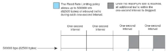
line
| Time Period | One-second Interval | One-second Interval (t) | One-second Interval (t) | | :--- | :--- | :--- | :--- | | 500000 bps (62500 bytes) | 1 | 1 | 1 | The Fixed Rate Limiting policy allows up to 500000 ats (62500 bytes) of inbound traffic during each one-second interval. Once the maximum rate is reached, all additional traffic within the one-second interval is dropped.Configuration notes
- Rate limiting is available only on inbound ports.
- The rate limit on IPv6 hardware takes several seconds to take effect at higher configured rate limit values. For example, if the configured rate limit is 750 Mbps, line-rate limiting could take up to 43 seconds to take effect.
Configuring a port-based rate limiting policy
To configure rate limiting on a port, enter commands such as the following.
PowerConnect(config)#interface ethernet 24 PowerConnect(config-if-e1000-24)#rate input fixed 500000
These commands configure a fixed rate limiting policy that allows port 24 to receive a maximum of 500000 bits per second (62500 bytes per second). If the port receives additional bytes during a given one-second interval, the port drops all inbound packets on the port until the next one-second interval starts.
Syntax: [no] rate-limit input fixed
For PowerConnect devices, the
Configuring an ACL-based rate limiting policy
IP ACL-based rate limiting of inbound traffic provides the facility to limit the rate for IP traffic that matches the permit conditions in extended IP ACLs. This feature is available in the Layer 2 and Layer 3 code.
To configure ACL-based rate limiting on a Dell PowerConnect device, you create individual traffic policies, then reference the traffic policies in one or more ACL entries (also called clauses or statements). The traffic policies become effective on ports to which the ACLs are bound.
For configuration procedures for ACL-based rate limiting, refer to Chapter 18, "Configuring Traffic
PowerConnect#show rate-limit fixed
Total rate-limited interface count: 11.
| Port | Configured Input Rate | Actual Input Rate |
| 1 | 1000000 | 1000000 |
| 3 | 10000000 | 10005000 |
| 7 | 10000000 | 10000000 |
| 9 | 7500000 | 7502000 |
| 11 | 8000000 | 7999000 |
| 12 | 8000000 | 7999000 |
| 13 | 8000000 | 7999000 |
| 14 | 8000000 | 7999000 |
| 15 | 8000000 | 7999000 |
| 21 | 8000000 | 8000000 |
| 25 | 7500000 | 7502000 |
Syntax: show rate-limit fixed
The command lists the ports on which fixed rate limiting is configured, and provides the information listed in Table 115 for each of the ports.
TABLE 115 CLI display of Fixed rate limiting information
| This field... Displays... |
| Total rate-limited interface count The total number of ports that are configured for Fixed rate limiting. |
| Port The port number. |
| Configured Input Rate The maximum rate requested for inbound traffic. The rate is measured in bits per second (bps). |
| Actual Input Rate The actual maximum rate provided by the hardware. The rate is measured In bps. |
Rate shaping overview
Outbound Rate Shaping is a port-level feature that is used to shape the rate and control the bandwidth of outbound traffic on a port. This feature smooths out excess and bursty traffic to the
- When outbound rate shaping is enabled on a port on an IPv4 device, the port QoS queuing method (qos mechanism) will be strict mode. This applies to IPv4 devices only. On IPv6 devices, the QoS mechanism is whatever method is configured on the port, even when outbound rate shaping is enabled.
- You can configure a rate shaper for a port and for the individual priority queues of that port. However, if a port rate shaper is configured, that value overrides the rate shaper value of a priority queue if the priority queue rate shaper is greater than the rate shaper for the port.
- On PowerConnect B-Series FCX devices, configured rate shaper values are rounded up to the nearest values programmable by the hardware.
Configuring outbound rate shaping for a port
To configure the maximum rate at which outbound traffic is sent out on a port, enter commands such as the following.
PowerConnect{config}#interface e 1/2 PowerConnect{config-If e1000-2}Rate limit output shaping 1300 • On PowerConnect B-Series FCX devices, the configured outbound rate shaper of 651 Kbps on port 1/15 is rounded to 616 Kbps. The configured 1300 Kbps limit on port 15 is rounded to 1232 Kbps..
Syntax: [no] rate-limit output shaping
On PowerConnect B-Series FCX devices, you can specify a value up to the port line rate for
Configuring outbound rate shaping for a specific priority
To configure the maximum rate at which outbound traffic is sent out on a port priority queue, enter commands such as the following.
PowerConnect(config)#interface e 1/2 PowerConnect(config-if-ol000-2)#rate-limit output shaping 500 priority 7
- OnPowerConnect B-Series FCX devices, the configured 500 Kbps limit for outbound traffic on priority queue 7 on port 2 is rounded to a value that is programmable by the hardware, which is 440 Kbps.
The above commands configure an outbound rate shaper on port 1/14 and port 1/15.
- On PowerConnect B-Series FCX devices, the configured outbound rate shaper (651 Kbps) on port 1/15 is the rounded to 616 Kbps. The configured 1300 Kbps limit on port 14 is rounded to 1232 Kbps.
Syntax: [no] rate-limit output shaping ethernet
Specify the
• PowerConnect B-Series FCX stackable switches -
Specify the
- On PowerConnect B-Series FCX devices, you can specify a
Displaying rate shaping configurations
To display the configured outbound rate shaper on a device, enter the following command.
PowerConnect#show rate-limit output-shaping
Outbound Rate Shaping Limits in Kbps:
| Port | PortMax | Prio0 | Prio1 | Prio2 | Prio3 | Prio4 | Prio5 | Prio6 | Prio7 |
| 1 | 651 | ||||||||
| 2 | 1302 | ||||||||
| 15 | 651 |
The display lists the ports on a device, the configured outbound rate shaper on a port and for a priority for a port.
Configuring IP Multicast Traffic Reduction for PowerConnect B-Series FCX Switches
Chapter
22
Table 116 lists the individual Dell PowerConnect switches and the IP multicast traffic reduction features they support.
TABLE 116 Supported IP multicast reduction features
| Feature PowerConnect B-Series FCX | |
| IGMP v1/v2 Snooping Global Yes | |
| IGMP v3 Snooping Global Yes(S.G) | |
| IGMP v1/v2/v3 Snooping per VLAN Yes | |
| IGMP v2/v3 Fast LeaveYes(membership tracking) | |
| PIM SM V2 Snooping Yes | |
| Multicast static group traffic filteringYes(for snooping scenarios) |
IGMP snooping overview
When a device processes a multicast packet, by default, the device broadcasts the packets to all ports except the incoming port of a VLAN. Packets are flooded by hardware without going to the CPU. This behavior causes some clients to receive unwanted traffic.
IGMP snooping provides multicast containment by forwarding traffic to only the ports that have IGMP receivers for a specific multicast group (destination address). A device maintains the IGMP
An IGMP device is responsible for broadcasting general queries periodically, and sending group queries when it receives a leave message, to confirm that none of the clients on the port still want specific traffic before removing the traffic from the port. IGMPv2 lets clients specify what group (destination address) will receive the traffic but not to specify the source of the traffic. IGMPv3 is for source-specific multicast traffic, adding the capability for clients to INCLUDE or EXCLUDE specific traffic sources. An IGMPv3 device port state could be INCLUDE or EXCLUDE, and there are different types of group records for client reports.
The interfaces respond to general or group queries by sending a membership report that contains one or more of the following records associated with a specific group:
- Current-state record that indicates from which sources the interface wants to receive and not receive traffic. This record contains the source address of interfaces and whether or not traffic will be included (IS_IN) or not excluded (IS_EX) from this source.
- Filter-mode-change record. If the interface state changes from IS_IN to IS_EX, a TO_EX record is included in the membership report. Likewise, if the interface state changes from IS_EX to IS_IN, a TO_IN record appears in the membership report.
- An IGMPv2 leave report is equivalent to a TO_IN (empty) record in IGMPv3. This record means that no traffic from this group will be received regardless of the source.
- An IGMPv2 group report is equivalent to an IS_EX (empty) record in IGMPv3. This record means that all traffic from this group will be received regardless of source.
- Source-list-change record. If the interface wants to add or remove traffic sources from its membership report, the report can contain an ALLOW record, which includes a list of new sources from which the interface wishes to receive traffic. It can also contain a BLOCK record, which lists the current traffic sources from which the interface wants to stop receiving traffic.
IGMP protocols provide a method for clients and a device to exchange messages, and let the device build a database indicating which port wants what traffic. The protocols do not specify forwarding methods. They require IGMP snooping or multicast protocols such as PIM or DVMRP to handle packet forwarding. PIM and DVMRP can route multicast packets within and outside a VLAN, while IGMP snooping can switch packets only within a VLAN. Currently, PowerConnect B-Series FCX devices do not support multicast routing.
If a VLAN is not IGMP snooping-enabled, it floods multicast data and control packets to the entire VLAN in hardware. When snooping is enabled, IGMP packets are trapped to the CPU. Data packets
The
NOTE
For this command to take effect, you must save the configuration and reload the switch.
The hardware resource limit applies only to the VLANs where IGMP snooping is enabled. Multicast streams are switched in hardware without using any pre-installed resources in a VLAN where snooping is not enabled.
PowerConnect B-Series FCX devices support up to 32K of IGMP groups, which are produced by client membership reports.
Configuration notes
- Servers (traffic sources) are not required to send IGMP memberships.
- The default IGMP version is V2.
- Hardware resource is installed only when there is data traffic. If a VLAN is configured for IGMPv3, the hardware matches (S G), otherwise it matches (* G).
- A user can configure the maximum numbers of groups and hardware switched data streams.
- The device supports static groups that apply to the entire VLAN, or to just a few ports. The device acts as a proxy to send IGMP reports for the static groups when receiving queries. The static group has a drop option to discard multicast data packets in hardware.
• A user can configure static router ports to force all multicast traffic to these specific ports. - The devices support fast leave for IGMPv2. Fast leave stops traffic immediately when the port receives a leave message.
- The devices support tracking and fast leave for IGMPv3, tracking all IGMPv3 clients. If the only client on a port leaves, traffic is stopped immediately.
- An IGMP device can be configured as a querier (active) or non-querier (passive). Queriers send queries. Non-queriers listen for queries and forward them to the entire VLAN.
■ Every VII AM can be independently configured to be a suvior or a non suvior.
The implementation allows snooping on some VLANs or all VLANs. Each VLAN can independently enable or disable IGMP, or configure V2 or V3. In general, global configuration commands ip multicast apply to every VLAN except those that have local multicast configurations (which supersede the global configuration). IGMP also allows independent configuration of individual ports in a VLAN for either IGMPv2 or IGMPv3. Configuring a specific version on a port or a VLAN only applies to the device's sent queries. The device always processes client reports of any version regardless of the configured version.
IGMP snooping requires hardware resources. If resources are inadequate, the data stream without a resource is mirrored to CPU in addition to being VLAN flooded, which can cause high CPU usage. Dell recommends that you avoid global enabling of snooping unless necessary.
When any port in a VLAN is configured for IGMPv3, the VLAN matches both source and group (S G) in hardware switching. If no ports are configured for IGMPv3, the VLAN matches group only (* G). Matching (S G) requires more hardware resources than matching (* G) when there are multiple servers sharing the same group. For example, two data streams from different sources to the same group require two (S G) entries in IGMPv3, but only one (* G) in IGMPv2. To conserve resources, IGMPv3 must be used only in source-specific applications. When VLANs are independently configured for versions, some VLANs can match (* G) while others match (S G).
IGMP snooping requires clients to send membership reports in order to receive data traffic. If a client application does not send reports, you must configure static groups to force traffic to client ports. A static group can apply to only some ports or to the entire VLAN.
Configuring queriers and non-queriers
An IGMP snooping-enabled device can be configured as a querier (active) or non-querier (passive). An IGMP querier sends queries; a non-querier listens for IGMP queries and forwards them to the entire VLAN. Also, VLANs can be independently configured to be queriers or non-queriers. If a VLAN has a connection to a PIM or DVMRP-enabled port on another router, the VLAN must be configured as a non-querier. When multiple IGMP snooping devices are connected together, and there is no connection to a PIM or DVMRP-enabled port, one of the devices must be configured as a querier. If multiple devices are configured as queriers, after these devices exchange queries, then all except the winner stop sending queries. The device with the lowest address becomes the querier. Although the system will work when multiple devices are configured as queriers, Dell recommends that only
VLAN specific configuration
You can configure IGMP snooping on some VLANs or on all VLANs. Each VLAN can be independently enabled or disabled for IGMP snooping, and can be configured for IGMPv2 or IGMPv3. In general, the ip multicast commands apply globally to all VLANs except those configured with VLAN-specific multicast commands. The VLAN-specific multicast commands supersede the global ip multicast commands.
Using IGMPv2 with IGMPv3
IGMP snooping can be configured for IGMPv2 or IGMPv3 on individual ports on a VLAN. An interface or router sends the queries and reports that include its IGMP version specified on it. The version configuration only applies to sending queries. The snooping device recognizes and processes IGMPv2 and IGMPv3 packets regardless of the version configuration.
To avoid version deadlock, an interface retains its version configuration even when it receives a report with a lower version.
PIM SM traffic snooping overview
When multiple PIM sparse routers connect through a snooping-enabled device, the device always forwards multicast traffic to these routers. For example, PIM sparse routers R1, R2, and R3 connect through a device. Assume R2 needs traffic, and R1 sends it to the device, which forwards it to both R2 and R3, even though R3 does not need it. A PIM snooping-enabled device listens to join and prune messages exchanged by PIM sparse routers, and stops traffic to the router that sends prune messages. This allows the device to forward the data stream to R2 only.
PIM SM traffic snooping requires IP multicast traffic reduction to be enabled on the device. IP multicast traffic reduction configures the device to listen for IGMP messages. PIM SM traffic snooping provides a finer level of multicast traffic control by configuring the device to listen specifically for PIM SM join and prune messages sent from one PIM SM router to another through the device.
FIGURE 114 PIM SM traffic reduction in an enterprise network

flowchart
graph TD
A["Layer 2 Switch"] --> B["Power"]
A --> C["Channel"]
A --> D["Server for Group"]
B --> E["Channel"]
B --> F["Server for Groups"]
C --> G["Channel"]
C --> H["Server for Groups"]
D --> I["Channel"]
D --> J["Server for Groups"]
style A fill:#f9f,stroke:#333
style B fill:#ccf,stroke:#333
style C fill:#cfc,stroke:#333
style D fill:#fcc,stroke:#333
NOTE
IP address 239.192.0.0/14 must be used for IPv4 Organization Local Scope.
When PIM SM traffic snooping is enabled, the device starts listening for PIM SM join and prune messages and IGMP group membership reports. Until the device receives a PIM SM join message or an IGMP group membership report, the device forwards IP multicast traffic out all ports. Once the device receives a join message or group membership report for a group, the device forwards subsequent traffic for that group only on the ports from which the join messages or IGMP reports were received.
In this example, the router connected to the receiver for group 239.255.162.1 sends a join message toward the group source. Because PIM SM traffic snooping is enabled on the device, the device examines the join message to learn the group ID, then makes a forwarding entry for the group ID and the port connected to the receiver router. The next time the device receives traffic for 239.255.162.1 from the group source, the device forwards the traffic only on port 5/1, because
Notice that the ports connected to the source and the receivers are all in the same port-based VLAN on the device. This is required for the PIM SM snooping feature. The devices on the edge of the Global Ethernet cloud are configured for IP multicast traffic reduction and PIM SM traffic snooping. Although this application uses multiple devices, the feature has the same requirements and works the same way as it does on a single device.
Configuring IGMP snooping
To configure IGMP snooping on an PowerConnect B-Series FCX devices, you need to perform the following global and VLAN-specific tasks.
Global tasks
Perform the following global tasks:
- "Configuring the hardware and software resource limits" on page 656
- "Enabling or disabling transmission and receipt of IGMP packets on a port" on page 656
- "Configuring the global IGMP mode" on page 656 (Must be enabled for IGMP snooping)
• "Modifying the age interval" on page 657 - "Modifying the query interval (active IGMP snooping mode only)" on page 657
- "Configuring the global IGMP version" on page 657
- "Configuring report control" on page 657 (rate limiting)
- "Modifying the wait time before stopping traffic when receiving a leave message" on page 658
- "Modifying the multicast cache age time" on page 658
- "Enabling or disabling error and warning messages" on page 658
- "Enabling or disabling PIM sparse snooping" on page 658
VLAN-specific tasks
Perform the following VI AN-specific tasks:
Configuring the hardware and software resource limits
The system supports up to 8K of hardware-switched multicast streams. The configurable range is from 256 through 8192 with a default of 512. Enter the following command to define the maximum number of IGMP snooping cache entries.
PowerConnect(config)# system-max igmp-snoop-mcache 8000
Syntax: [no] system-max igmp-snoop-mcache
The system supports up to 32K of groups. The configurable range is from 256 through 32768 and the default is 8192. The configured number is the upper limit of an expandable database. Client memberships exceeding the group limits are not processed. Enter the following command to define the maximum number of IGMP group addresses.
PowerConnect{config}# system-max 1qmp-max-group-addr 1600
Syntax: [no] system-max igmp-max-group-addr
Enabling or disabling transmission and receipt of IGMP packets on a port
When a VLAN is snooping-enabled, all IGMP packets are trapped to CPU without hardware VLAN flooding. The CPU can block IGMP packets to and from a multicast-disabled port, and does not add it to the output interfaces of hardware resources. This prevents the disabled port from receiving multicast traffic. However, if static groups to the entire VLAN are defined, the traffic from these groups is VLAN flooded, including to disabled ports. Traffic from disabled ports cannot be blocked in hardware, and is switched in the same way as traffic from enabled ports.
This command has no effect on a VLAN that is not snooping-enabled because all multicast traffic is VLAN flooded.
PowerConnect(config)# interface ethernet 0/1/3
PowerConnect(config-if-ol000-0/1/3)# ip-multicast-disable
Syntax: [no] ip-multicast-disable
Configuring the global IGMP mode
Modifying the age interval
When the device receives a group membership report, it makes an entry for that group in the IGMP group table. The age interval specifies how long the entry can remain in the table before the device receives another group membership report. When multiple devices connect together, all devices must be configured for the same age interval, which must be at least twice the length of the query interval, so that missing one report won't stop traffic. Non-querier age intervals must be the same as the age interval of the querier.
To modify the age interval, enter the following command.
PowerConnect(config)# ip multicast age-interval 280
Syntax: [no] ip multicast age-interval
The
Modifying the query interval (active IGMP snooping mode only)
For a device with an active IGMP mode, you can modify the query interval to specify how often the device sends general queries. When multiple queriers connect together, they must all be configured with the same query interval.
To modify the query interval, enter the following command.
PowerConnect(config)# ip multicast query-interval 120
Syntax: [no] ip multicast query-interval
The
Configuring the global IGMP version
You can globally specify IGMPv2 or IGMPv3 for the device. The default is IGMPv2. For example, the following command causes the device to use IGMPv3.
PowerConnect (nonfinal) in multiclass version 3
IGMPv2 membership reports of the same group from different clients are considered to be the same and are rate-limited.
Use the following command to alleviate report storms from many clients answering the upstream router query.
PowerConnect(config)# ip multicast report-control
Syntax: [no] ip multicast report-control
The original command, ip igmp-report-control, has been renamed to ip multicast report-control. The original command is still accepted; however, it is renamed when you issue a show configuration command.
Modifying the wait time before stopping traffic when receiving a leave message
You can define the wait time before stopping traffic to a port when a leave message is received. The device sends group-specific queries once per second to ask if any client in the same port still needs this group. The value range is from 1 through 5, and the default is 2. Due to internal timer granularity, the actual wait time is between n and (n + 1) seconds (n is the configured value).
PowerConnect(config)# ip multicast leave-wait-time 1
Syntax: [no] ip multicast leave-wait-time
Modifying the multicast cache age time
You can set the time for an mcache to age out when it does not receive traffic. The traffic is hardware switched. One minute before aging out an mcache, the device mirrors a packet of this mcache to CPU to reset the age. If no data traffic arrives within one minute, this mcache is deleted. A lower value quickly removes resources consumed by idle streams, but it mirrors packets to CPU often. A higher value is recommended only data streams are continually arriving. The range is from 60 through 3600 seconds, and the default is 60 seconds.
PowerConnect{config}# ip multicast mcache-age 180
Syntax: [no] ip multicast mcache-age
Syntax: [no] ip pimsm-snooping
NOTE
The device must be in passive mode before it can be configured for PIM snooping.
Configuring the IGMP mode for a VLAN
You can configure a VLAN to use the active or passive IGMP mode. The default mode is passive. The setting specified for the VLAN overrides the global setting:
- Active - An active IGMP mode device actively sends out IGMP queries to identify multicast groups on the network, and makes entries in the IGMP table based on the group membership reports received.
- Passive - A passive IGMP mode device forwards reports to the router ports which receive queries. IGMP snooping in the passive mode forwards queries to the entire VLAN, but it does not send queries.
To set the IGMP mode for VLAN 20 to active, enter the following commands.
PowerConnect(config)# vlan 20
PowerConnect(config-vlan-20)† multicast active
Syntax: [no] multicast active | passive
Disabling IGMP snooping for the VLAN
When IGMP snooping is enabled globally, you can still disable it for a specific VLAN. For example, the following commands cause IGMP snooping to be disabled for VLAN 20. This setting overrides the global setting.
PowerConnect(config)# vlan 20
PowerConnect(config-vlan-20)# multicast disable-multicast-snoop
Syntax: [no] multicast disable-multicast-snoop
Enabling PIM sparse mode snooping for the VLAN
Configuring the IGMP version for the VLAN
You can specify the IGMP version for a VLAN. For example, the following commands configure VLAN 20 to use IGMPv3.
PowerConnect(config)# vlan 20
PowerConnect(config-vlan-20)4 multicast version 3
Syntax: [no] multicast version 2 | 3
If no IGMP version is specified, then the globally-configured IGMP version is used. If an IGMP version is specified for individual ports, those ports use that version, instead of the VLAN version.
Configuring the IGMP version for individual ports
You can specify the IGMP version for individual ports in a VLAN. For example, the following commands configure ports 0/1/4, 0/1/5, 0/1/6 and 0/2/1 to use IGMPv3. The other ports either use the IGMP version specified with the multicast version command, or the globally-configured IGMP version.
PowerConnect(config)# vlan 20
PowerConnect(config-vlan-20)‡ multicast port-version 3 ethernet 0/2/1 ethernet 0/1/4 to 0/1/6
Syntax: [no] multicast port-version 2 | 3
Configuring static groups to the entire VLAN or to specific ports
A snooping-enabled VLAN cannot forward multicast traffic to ports that do not receive IGMP membership reports. If clients cannot send reports, you can configure a static group which applies to the entire VLAN or only to specific ports. The static group allows packets to be forwarded to the static group ports even though they have no client membership reports. The static group to the entire VLAN is used in VLAN flooding, which consumes less hardware resource than the static group to ports.
The static group drop option discards data traffic to a group in hardware. The group can be any multicast group including groups in the reserved range of 224.0.0.X. The drop option does not apply to ICMP packets, which are always trapped to CPU when opening is enabled. The drop
Configuring static router ports
FastIron Stackable devices forward all multicast control and data packets to router ports which receive queries. Although router ports are learned, you can force multicast traffic to specified ports even though these ports never receive queries. To configure static router ports, enter the following commands.
PowerConnect(config)# vlan 70
PowerConnect(config-vlan-70)† multicast router-port ethernet 0/1/4 to 0/1/5 ethernet 0/1/8
Syntax: [no] multicast router-port ethernet
Specify the
To specify a list of ports, enter each port as ethernet
To specify a range of ports, enter the first port in the range as ethernet
You can combine lists and ranges in the same command. For example: enable ethernet 0/1/1 to 0/1/8 ethernet 0/1/24 ethernet 0/2/2 ethernet 0/2/4.
Turning off static group proxy
If a device has been configured for static groups, it acts as a proxy and sends membership reports for the static groups when it receives general or group-specific queries. When a static group configuration is removed, it is deleted from active group table immediately. However, leave messages are not sent to the querier, and the querier must age the group out. Proxy activity can be turned off. The default is on. To turn proxy activity off for VLAN 20, enter the following commands.
PowerConnect(config)# vlan 20
PowerConnect(config-vlan-20)# multicast proxy-off
Syntax: [no] multicast proxy-off
Enabling IGMPv3 membership tracking and fast leave for the VLAN
Every group on a physical port keeps its own tracking record. However, it can only track group membership; it cannot track by (source, group). For example, Client A and Client B belong to group1 but each receives traffic streams from different sources. Client A receives a stream from (source_1, group1) and Client B receives a stream from (source_2, group1). The device still waits for the configured leave-wait-time before it stops the traffic because these two clients are in the same group. If the clients are in different groups, then the waiting period is not applied and traffic is stopped immediately.
To enable the tracking and fast leave feature for VLAN 20, enter the following commands.
PowerConnect(config)# vlan 20
PowerConnect(config-vlan-20)↑ multicast tracking
Syntax: [no] multicast tracking
The membership tracking and fast leave features are supported for IGMPv3 only. If any port or any client is not configured for IGMPv3, then the multicast tracking command is ignored.
Configuring fast leave for IGMPv2
When a device receives an IGMPv2 leave message, it sends out multiple group-specific queries. If no other client replies within the waiting period, the device stops forwarding traffic. When fast-leave-v2 is configured, and when the device receives a leave message, it immediately stops forwarding to that port. The device does not send group specific queries. You must ensure that no snooping-enabled ports have multiple clients. When two devices connect together, the querier must not be configured for fast-leave-v2, because the port might have multiple clients through the non-querier. The number of queries, and the waiting period (in seconds) can be configured using the ip multicast leave-wait-time command. The default is 2 seconds.
To configure fast leave for IGMPv2, enter the following commands.
PowerConnect(config)# vlan 20
PowerConnect(config-vlan-20)† multicast fast-leave-v2
Syntax: [no] multicast fast-leave-v2
Enabling fast convergence
Displaying IGMP snooping information
This section describes the show commands for IGMP snooping.
Displaying IGMP errors
To display information about possible IGMP errors, enter the following commands.
PowerConnect# show ip multicast error
snap SW processed pkt: 173, up-time 160 sec
Syntax: show ip multicast error
The following table describes the output from the show ip multicast error command.
Field Description
| SW processed pkt The number of multicast packets processed by IGMP snooping. |
up-time The time since the IGMP snooping is enabled.
Displaying IGMP group information
To display information about IGMP groups, enter the following command.
PowerConnect# show ip multicast group
p::physical, ST:static, QR:querier, EX:exclude, IN:include, Y:yes, N:no
VL70 : 3 groups, 4 group-port, tracking_enabled
| group | p-port | ST | QR | life mode | source | ||
| 1 | 224.1.1.2 | 0/1/33 | no | yes | 120 | EX | 0 |
| 2 | 224.1.1.1 | 0/1/33 | no | yes | 120 | EX | 0 |
| 3 | 226.1.1.1 | 0/1/35 | yes | yes | 100 | EX | 0 |
| 4 | 226.1.1.1 | 0/1/33 | yes | yes | 100 | EX | 0 |
In this example, an IGMPv2 group is in EXCLUDE mode with a source of 0. The group only excludes
traffic from the 0 (zero) source list, which actually means that all traffic sources are included.
To display detailed IGMP group information, enter the following command.
PowerConnect# show ip multicast group 224.1.1.1 tracking
Display group 224.1.1.1 in all interfaces with tracking enabled.
p-physical, ST:static, QR:querior, EX:exclude, IN:include, Y:yes, N:no VL70 : 1 groups, 1 group-port, tracking enabled
group p-port ST QR life mode source
*** Note: has l static groups to the entire vlan, not displayed here
1 224.1.1.1 0/1/33 no yes 100 RX 0
receive reports from l clients: (age)
(2.2.100.2 69)
Syntax: show ip multicast group [
If you want a report for a specific multicast group, enter that group's address for
Enter detail to display the source list of a specific VLAN.
Enter tracking for information on interfaces that have tracking enabled.
The following table describes the information displayed by the show ip multicast group command.
Field Description
| group The address of the group (destination address in this case, 224.1.1.1) | |
| p-port The physical port on which the group membership was received. | |
| ST | Yes indicates that the IGMP group was configured as a static group; No means the address was learned from reports. |
| QR | Yes means the port is a querier port; No means it is not. A port becomes a non-querier port when it receives a query from a source with a lower source IP address than the device. |
| life The number of seconds the group can remain in EXCLUDE mode. An EXCLUDE mode changes to INCLUDE mode if it does not receive an "IS_EX" or "TO_EX" message during a certain period of time. The default is 140 seconds. There is no life displayed in INCLUDE mode. | |
| mode Indicates current mode of the interface: INCLUDE or EXCLUDE. If the interface is in INCLUDE mode, it admits traffic only from the source list. If an interface is in EXCLUDE mode, it denies traffic from the source list and accepts the rest. | |
source Identifies the source list that will be included or excluded on the Interface. For example, if an IGMPv2 group is in EXCLUDE mode with a source of 0, the group excludes
Syntax: show ip multicast mcache
The following table describes the output of the show ip multicast mcache command.
Field Description
| (source group) Source and group addresses of this data stream. (* group) means match group only; (source group) means match both. | |
| cnt The number of packets processed in software. Packets are switched in hardware, which increases this number slowly. | |
| 0IF | The output interfaces. If entire vlan is displayed, this indicates that static groups apply to the entire VLAN. |
| ago The mcache ago. The mcache will be reset to 0 if traffic continues to arrive. otherwise the mcache will be aged out when it reaches the time defined by the lp multicast mcache-age command. | |
| uptime The up time of this mcache in minutes. | |
| vidx Vidx specifies output port list index. Range is from 4096 to 8191 | |
| ref-cnt The vidx is shared among mcaches having the same output interfaces. Ref-cnt indicates the number of mcaches using this vidx. | |
Displaying PIM sparse snooping information
PIM sparse mode snooping allows a device to listen for join or prune messages exchanged between PIM routers, which helps reduce unwanted traffic. To display PIM snooping information, enter the following command.
PowerConnect# show ip multicast pimsm-snooping
vlan 1, has 1 caches.
1 (1.2.10.102 225.1.1.1) has 0 pim join ports out of 1 OIF
vlan 70, has 1 caches.
1 (* 226.1.2.3) has 2 pim join ports out of 2 OIF
0/1/14 (age=60), 0/1/13 (age=60),
0/1/14 bas 1 src: 1.1.30.99(60)
0/1/13 has 1 src: 1.1.30.99(60)
Syntax: show ip multicast resource
The following table describes the output from the show ip multicast resource command.
Field Description
| alloc The allocated number of units. | |
| in-use The number of units which are currently being used. | |
| avail The number of available units. | |
| get-fail This displays the number of resource failures.NOTE: It is important to pay attention to this field. | |
| limit | The upper limit of this expandable field. The limit of multicast group is configured by the system-max igmp-max-group-addr command. The limit of snoop mcache entry is configured by the system-max multicast-snoop-mcache command. |
| get-mem The number of memory allocation. This number should continue to increase. | |
| size The size of a unit (in bytes). | |
| init The initial allocated amount of memory. More memory can be allocated if resources run out. | |
| Available vidx The output Interface (OIF) port mask used by mcache. The entire device has a maximum of 4096 vidx. Different mcache with the same OIF share the same vidx. If vidx is not available, the stream cannot be hardware-switched. | |
Displaying status of IGMP snooping traffic
To display status information for IGMP snooping traffic, enter the following command.
| PowerConnect show ip multicast trafficIGMF snooping: Total Rcv: 22, Xmt: 26 | |||||||
| 0: query, Qry: general 0, G-Qry: group 0, GSQry: group-source 0, Mbr: member | |||||||
| Rcv | QryV2 | QryV3 | G-Qry | CSQry | MbrV2 | MbrV3 | Leave |
| VL1 | 0 | 0 | 0 | 0 | 4 | 0 | 0 |
| VL70 | 18 | 0 | 0 | 0 | 0 | 0 | 0 |
| Recv | IsIN | IsEX | ToIN | ToEX | ALLOW | BLOCK | Pkt-Err |
| VL1 | 0 | 4 | 0 | 0 | 0 | 0 | 0 |
| VL70 | 0 | 0 | 0 | 0 | 0 | 0 | 0 |
| Field | Description |
| GSQry Number of group source specific queries received or sent. | |
| Mbr The membership report. | |
| MbrV2 The IGMPv2 membership report. | |
| MbrV3 The IGMPv3 membership report. | |
| IsIN Number of source addresses that were included in the traffic. | |
| IsEX Number of source addresses that were excluded in the traffic. | |
| ToIN Number of times the interface mode changed from EXCLUDE to INCLUDE. | |
| ToEX Number of times the interface mode changed from INCLUDE to EXCLUDE. | |
| ALLO Number of times that additional source addresses were allowed on the interface. | |
| BLK Number of times that sources were removed from an interface. | |
| Pkt-Err Number of packets having errors, such as checksum. | |
| Pimsm-snooping hello, join, Number of PIM sparse hello, join, and prune packets prune | |
Displaying IGMP snooping information by VLAN
You can display IGMP snooping information for all VLANs or for a specific VLAN. For example, to display IGMP snooping information for VLAN 70, enter the following command.
PowerConnect† show ip multicast vlan 70
version-2, query t-30, group aging t-140, max resp t-3, other qr present t-63
VL70: dft V2, vlan cfg passive, , pimsm (vlan cfg), track, 0 grp, 1 (*G) cache, rtr ports,
router ports: 0/1/13(140) 1.1.70.3, 0/1/20(180) 1.1.70.2, 0/1/14(180)
0/1/13 has 0 groups, non-QR (passive), default V2
0/1/14 has 0 groups, non-QR (passive), default V2
0/1/20 has 0 groups, non-QR (passive), default V2
Syntax: show ip multicast vlan [
Field Description
| QR Indicates that the port is a querler. | |
| dft | The IGMP version for the specified VLAN. In this example, VL70: dft V2 indicates that the default IGMP version V2 is set for VLAN 70. |
Displaying querier information
You can use the show ip multicast vlan command to display the querier information for a VLAN. This command displays the VLAN interface status and if there is any other querier present with the lowest IP address. The following list provides the combinations of querier possibilities:
• Active interface with no other querier present
• Passive interface with no other querier present
• Active interface with other querier present
• Passive interface with other querier present
Active interface with no other querier present
The following example shows the output in which the VLAN interface is active and no other querier is present with the lowest IP address.
PowerConnect# show ip multicast vlan 10
Version=2, Intervals: Query=125, Group Age=260, Max Resp=10, Other Qr=260
VL10: dft V2, vlan cfg active, 0 grp, 0 (*G) cache, no rtr port,
1/1/16 has 0 groups, This interface is Querier default v2
1/1/24 has 0 groups, This interface is Querier default V2
2/1/16 has 0 groups.
Passive interface with no other querier present
The following example shows the output in which the VLAN interface is passive and no other querier is present with the lowest IP address.
PowerConnect# show ip multicast vlan 10
Version=2, Intervals: Query=125, Group Age=260, Max Resp=10, Other Qr=260
VL10: dft V2, vlan cfg passive, 0 grp, 0 (*G) cache, no rtr port,
1/1/16 has 0 groups,
This interface is non-Querier (passive)
default v2
1/1/24 has 0 groups,
This interface is non-Querier (passive)
default V2
2/1/16 has 0 groups,
This interface is non-Querier (passive)
default V2
2/1/24 has 0 groups,
This interface is non-Querier (passive)
default v2
3/1/1 has 0 groups,
This interface is non-Querier (passive)
default V2
3/1/4 has 0 groups,
This interface is non-Querier (passive)
default v2
Active interface with other querier present
The following example shows the output in which the VLAN interface is active and another querier is present with the lowest IP address.
This interface is Querier
default v2
group: 226.6.6.8, life = 240
group: 228.8.8.8, life = 240
group: 230.0.0.0, life = 240
group: 224.4.4.4, life = 240
2/1/24 has 2 groups,
This interface is non-Querier
Querier is 5.5.5.5
Age 15 0
Max response time is 100
default V2
**** Warning! has v3 (age=0) nbrs
group: 234.4.4.4, life = 260
group: 226.5.6.6, life = 260
3/1/1 has 4 groups,
This interface is Querier
default V2
group: 238.8.8.8, life = 260
group: 228.8.8.8, life - 260
group: 230.0.0.0, life = 260
group: 224.4.4.4, life = 260
3/1/4 has 1 groups,
This interface is non-Querier
Querier is 8.8.8.8
Age 1s 0
Max response time is 100
default v2
**** Warning! has V3 (age=0) nbrs
group: 236.6.6.6, life = 260
Passive interface with other querier present
The following example shows the output in which the VLAN interface is passive and another querier is present with the lowest IP address.
This interface is non-Querier (passive)
default v2
group: 226.6.6.8, life = 260
group: 228.8.8.8, life = 260
group: 230.0.0.0, life = 260
group: 224.4.4.4, life = 260
2/1/24 has 2 groups,
This interface is non-Querier (passive)
Querier is 5.5.5.5
Age 15 0
Max response time is 100
default V2
**** Warning! has v3 (age=0) nbrs
group: 234.4.4.4, life = 260
group: 226.5.6.6, life = 260
3/1/1 has 4 groups,
This interface is non-Querier (passive)
default V2
group: 238.8.8.8, life = 260
group: 228.8.8.8, life - 260
group: 230.0.0.0, life = 260
group: 224.4.4.4, life = 260
3/1/4 has 1 groups,
This interface is non-Querier (passive)
Querier is 8.8.8.8
Age 1s 0
Max response time is 100
default v2
**** Warning! has V3 (age=0) nbrs
group: 236.6.6.6, life = 260
Clear IGMP snooping commands
The clear IGMP snooping commands must be used only in troubleshooting conditions, or to recover from errors.
Clear mcache on a specific VLAN
To clear the mcache on a specific VLAN, enter the following command.
PowerConnect# clear ip multicast vlan 10 mcache
Syntax: clear ip multicast vlan
The
Clear traffic on a specific VLAN
To clear the traffic counters on a specific VLAN, enter the following command.
PowerConnect# clear ip multicast vlan 10 traffic
Syntax: clear ip multicast vlan
The
Enabling the Foundry Discovery Protocol (FDP) and Reading 23 Cisco Discovery Protocol (CDP) Packets
Table 117 lists individual Dell PowerConnect switches and the discovery protocols they support.
TABLE 117 Supported discovery protocol features
| Feature | PowerConnect B-Series FCX |
| Foundry Discovery Protocol (FDP) for IPv4 and IPv6 traffic | Yes |
| Cisco Discovery Protocol (CDP) for IPv4 and IPv6 traffic | Yes |
Using FDP
The Foundry Discovery Protocol (FDP) enables Dell PowerConnect devices to advertise themselves to other Dell PowerConnect devices on the network. When you enable FDP on a Dell PowerConnect device, the device periodically advertises information including the following:
- Hostname (device ID)
• Product platform and capability - Software version
- VLAN and Layer 3 protocol address information for the port sending the update. IP, IPX, and AppleTalk Layer 3 information is supported.
A Dell PowerConnect device running FDP sends FDP updates on Layer 2 to MAC address 01-E0-52-CC-CC-CC. Other Dell PowerConnect devices listening on that address receive the updates and can display the information in the updates. Dell PowerConnect devices can send and
PowerConnect(config)# fdp run
Syntax: [no] fdp run
The feature is disabled by default.
Enabling FDP at the interface level
You can enable FDP at the interface level by entering commands such as the following.
PowerConnect(config)# int e 2/1
PowerConnect(config-if-2/1)# fdp enable
Syntax: [no] fdp enable
By default, the feature is enabled on an interface once FDP is enabled on the device.
Specifying the IP management address to advertise
When FDP is enabled, by default, the device advertises one IPv4 address and one IPv6 address to its FDP neighbors. If desired, you can configure the device to advertise only the IPv4 management address or only the IPv6 management address. You can set the configuration globally on a Layer 2 switch, or on an interface on a Layer 3 switch.
For example, to configure a Layer 2 switch to advertise the IPv4 address, enter the following command at the Global CONFIG level of the CLI:
PowerConnect(config) ^4 fdp advertise ipv4
To configure a Layer 3 switch to advertise the IPv6 address, enter the following command at the Interface level of the CLI:
PowerConnect(config-if-2/1)# fdp advertise ipv6
Syntax: fdp advertise ipv4 | ipv6
Changing the FDP update timer
By default, a Dell PowerConnect device enabled for FDP sends an FDP update every 60 seconds.
To change the FDP hold time, enter a command such as the following at the global CONFIG level of the CLI.
PowerConnect(config)# fdp holdtime 360
Syntax: [no] fdp holdtime
The
Displaying FDP information
You can display the following FDP information:
• FDP entries for Dell PowerConnect neighbors
• Individual FDP entries
- FDP information for an interface on the device you are managing
- FDP packet statistics
NOTE
If the Dell PowerConnect device has intercepted CDP updates, then the CDP information is also displayed.
Displaying neighbor information
To display a summary list of all the Dell PowerConnect neighbors that have sent FDP updates to this Dell PowerConnect device, enter the following command.
PowerConnectA ^12 show fdp neighbor Capability Codes: R - Router, T - Trans Bridge, B - Source Route Bridge S - Switch, E - Host, I - IGMP, r - Repeater (*) indicates a CDP device
Device ID
Local Int
Holdtm Capability Platform
Port ID
TABLE 118 Summary FDP and CDP neighbor information (Continued)
| This line... Displays... |
| Capability The role the neighbor is capable of playing in the network. |
| Platform The product platform of the neighbor. |
| Port ID The interface through which the neighbor sent the update. |
To display detailed information, enter the following command.
| PowerConnectA4 show fdp neighbor detail |
| Device ID: PowerConnect E configured as default VLAN1, tag-type8100 |
| Entry address(es): |
| IP address: 192.168.0.13 |
| IPV6 address (Global): certificate: certificate |
| Platform: PowerConnect Router, Capabilities: Router |
| Interface: Eth 2/9 |
| Port ID (outgoing port): Eth 2/9 is TAGGED in following VLAN(s): |
| 9 10 11 |
| Boldtime : 176 seconds |
| Version : |
| Foundry, Inc. Router, IronWare Version 07.6.0lblT53 Compiled on Aug 29 |
| 2002 at 10:35:21 labeled as B2R07601b1 |
The show fdp neighbor detail command displays the following information.
TABLE 119 Detailed FDP and CDP neighbor information
| This line... Displays... |
| Device ID The hostname of the neighbor. In addition, this line lists the VLAN memberships and other VLAN information for the neighbor port that sent the update to this device. |
| Entry address(cs) The Layer 3 protocol addresses configured on the neighbor port that sent the update to this device. If the neighbor is a Layer 2 Switch, this field lists the management IP address. |
| Platform The product platform of the neighbor. |
Canabilities: The role the neighbor is capable of playing in the network.
PowerConnectA4 show fdp entry PowerConnect B
Device ID: PowerConnect B configured as default VLAN1, tag-type8100
Entry addresses(a):
Platform: PowerConnect Router, Capabilities: Router
Interface: Eth 2/9
Port ID (outgoing port): Eth 2/9 is TAGGED in following VLAN(s):
9 10 11
Holdtime : 176 seconds
Version :
Foundry, Inc. Router, IronWare Version 07.6.01b153 Compiled on Aug 29
2002 at 10:35:21 labeled as B2R07601b1
Syntax: show fdp entry * |
The * |
Displaying FDP information for an interface
To display FDP information for an interface, enter a command such as the following.
PowerConnectA! show fdp interface ethernet 2/3
FastEthernet2/3 is up, line protocol is up
Encapsulation ethernet
Sending FDP packets every 5 seconds
Holdtime is 180 seconds
This example shows information for Ethernet port 2/3. The port sends FDP updates every 5 seconds. Neighbors that receive the updates can hold them for up to 180 seconds before discarding them.
Syntax: show fdp interface [ethernet
The ethernet
Displaying FDP and CDP statistics
The same commands clear information for both FDP and CDP.
Clearing FDP and CDP neighbor information
To clear the information received in FDP and CDP updates from neighboring devices, enter the following command.
PowerConnect# clear fdp table
Syntax: clear fdp table
NOTE
This command clears all the updates for FDP and CDP.
Clearing FDP and CDP statistics
To clear FDP and CDP statistics, enter the following command.
PowerConnect# clear fdp counters
Syntax: clear fdp counters
Reading CDP packets
Cisco Discovery Protocol (CDP) packets are used by Cisco devices to advertise themselves to other Cisco devices. By default, Dell PowerConnect devices forward these packets without examining their contents. You can configure a Dell PowerConnect device to intercept and display the contents of CDP packets. This feature is useful for learning device and interface information for Cisco devices in the network.
Dell PowerConnect devices support intercepting and interpreting CDP version 1 and version 2 packets.
NOTE
The Dell PowerConnect device can interpret only the information fields that are common to both CDP
Enabling interception of CDP packets on an interface
You can disable and enable CDP at the interface level.
You can enter commands such as the following.
PowerConnect(config)# int e 2/1
PowerConnect(config-1f-2/1)# cdp enable
Syntax: [no] cdp enable
By default, the feature is enabled on an interface once CDP is enabled on the device.
Displaying CDP information
You can display the following CDP information:
- Cisco neighbors
• CDP entries for all Cisco neighbors or a specific neighbor - CDP packet statistics
Displaying neighbors
To display the Cisco neighbors the Dell PowerConnect device has learned from CDP packets, enter the following command.
PowerConnect show fdp neighbors
Capability Codes: R - Router, T - Trans Bridge, B - Source Route Bridge
S - Switch, H - Host, I - ICMP, r - Repeater
(*) indicates a Cisco device
Device ID Local Int Holdtm Capability Platform Port ID
(A)Router Eth 1/1 124 R clusco RSP4
FastEthernet5/0/0
To display detailed information for the neighbors, enter the following command.
PowerConnect# show fdp neighbors ethernet 1/1
Device ID: Router
Entry address(os):
IP address: 207.95.6.143
Platform: cisco RSP4, Capabilities: Router
Interface: Eth 1/1, Port ID (outgoing port): FastEthernet5/0/0
HoldTime : 127 seconds
Version :
Cisco Internetwork Operating System Software
IOS (tm) RSP Software (RSP-JSV-M), Version 12.0(3)T1, RELEASE SOFTWARE (fcl)
Copyright (c) 1986-1999 by cisco Systems, Inc.
Compiled Thu 19-Aug-98 04:12 by cmong
Syntax: show fdp neighbors [detail | ethernet
Displaying CDP entries
To display CDP entries for all neighbors, enter the following command.
PowerConnect show fdp entry *
Device ID: Router
Entry address(mz):
IF address: 207.85.6.143
Platform: cisco RSP4, Capabilities: Router
Interface: Rth 1/1, Port ID (outgoing port): PassEthernet5/0/0
Holdtime : 124 seconds
Version :
Cisco Internetwork Operating System Software
IOS (tm) RSP Software (RSP JSV M), Version 12.0(5)T1, RELEASE SOFTWARE (fc1)
Copyright (c) 1956-1999 by cisco Systems, Inc.
Compiled: Thu 19-Aug-99 04:12 by comog
To display CDP entries for a specific device, specify the device ID. Here is an example.
PowerConnect ^1 show fdp entry Router1
PowerConnect# show fdp traffic
CDP counters:
Total packets output: 0, Input: 3
Hdr syntax: 0, Chksum error: 0, Encaps failed: 0
No memory: 0, Invalid packet: 0, Fragmented: 0
Syntax: show fdp traffic
Clearing CDP information
You can clear the following CDP information:
• Cisco Neighbor information
- CDP statistics
To clear the Cisco neighbor information, enter the following command.
PowerConnect ^1 clear fdp table
Syntax: clear fdp table
To clear CDP statistics, enter the following command.
PowerConnect† clear fdp counters
Syntax: clear fdp counters
Table 120 lists the individual Dell PowerConnect switches and the Link Layer Discovery Protocol (LLDP) features they support.
TABLE 120 Supported LLDP features
| Feature PowerConnect B-Series FCX | |
| LLDP | Yes |
| LLDP-MED Yes | |
| Support for tagged LLDP packets Yes | |
| IPv4 management address advertisement | Yes |
| IPv6 management address advertisement | Yes |
| LLDP operating mode setting per port Yes | |
| Setting the maximum number of LLDP neighbors | Yes |
| SNMP and Syslog messages Yes | |
| LLDP transmission intervals Yes | |
| Holdtime multiplier for transmit TTL Yes | |
| Configuring the minimum time between port reinitializations | Yes |
| Fast start repeat count for LLDP-MED Yes | |
Location ID for LLDP-MED Yes
The information generated by LLDP and LLDP-MED can be used to diagnose and troubleshoot misconfigurations on both sides of a link. For example, the information generated can be used to discover devices with misconfigured or unreachable IP addresses, and to detect port speed and duplex mismatches.
LLDP and LLDP-MED facilitate interoperability across multiple vendor devices. Dell PowerConnect devices running LLDP can interoperate with third-party devices running LLDP.
The Dell LLDP and LLDP-MED implementation adheres to the IEEE 802.1AB and TIA-1057 standards.
Terms used in this chapter
Endpoint device - An LLDP-MED device located at the network edge, that provides some aspect of IP communications service based on IEEE 802 LAN technology. An Endpoint device is classified in one of three class types (I, II, or III) and can be an IP telephone, softphone, VoIP gateway, or conference bridge, among others.
LLDP agent – The protocol entity that implements LLDP for a particular IEEE 802 device. Depending on the configured LLDP operating mode, an LLDP agent can send and receive LLDP advertisements (frames), or send LLDP advertisements only, or receive LLDP advertisements only.
LLDPDU (LLDP Data Unit) - A unit of information in an LLDP packet that consists of a sequence of short variable length information elements, known as TLVs. LLDP pass-through is not supported in conformance to IEEE standard.
MIB (Management Information Base) - A virtual database that identifies each manageable object by its name, syntax, accessibility, and status, along with a text description and unique object identifier (OID). The database is accessible by a Network Management Station (NMS) using a management protocol such as the Simple Network Management Protocol (SNMP).
Network connectivity device - A forwarding 802 LAN device, such as a router, switch, or wireless access point.
Station - A node in a network.
TLV (Type-Length-Value) - An information element in an LLDPDU that describes the type of
LLDP overview
FIGURE 115 LLDP connectivity
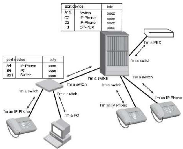
flowchart
graph TD
A["Port Device"] -->|A19 Switch, C2 IP-Phone, D2 IP-Phone, F3 OP-PBX Info| B["Server"]
B -->|I'm a switch, I'm a switch, I'm an IP Phone, I'm an IP Phone| C["Computer"]
C -->|I'm an IP Phone, Switch, PC Switch| D["Switch"]
D -->|I'm a switch, I'm a switch, I'm an IP Phone| E["Computer"]
E -->|I'm a switch, I'm a switch, I'm an IP Phone| F["Switch"]
F -->|I'm a switch, I'm a switch, I'm an IP Phone| G["Computer"]
G -->|I'm an IP Phone, Switch, PC Switch| H["Switch"]
H -->|I'm an IP Phone, Switch, PC Switch| I["Computer"]
I -->|I'm an IP Phone, Switch, PC Switch| J["Switch"]
J -->|I'm an IP Phone, Switch, PC Switch| K["Computer"]
K -->|I'm an IP Phone, Switch, PC Switch| L["Switch"]
L -->|I'm an IP Phone, Switch, PC Switch| M["Computer"]
M -->|I'm an IP Phone, Switch, PC Switch| N["Switch"]
N -->|I'm an IP Phone, Switch, PC Switch| O["Computer"]
O -->|I'm an IP Phone, Switch, PC Switch| P["Switch"]
P -->|I'm an IP Phone, Switch, PC Switch| Q["Computer"]
Q -->|I'm an IP Phone, Switch, PC Switch| R["Switch"]
R -->|I'm an IP Phone, Switch, PC Switch| S["Computer"]
S -->|I'm an IP Phone, Switch, PC Switch| T["Switch"]
T -->|I'm an IP Phone, Switch, PC Switch| U["Computer"]
U -->|I'm an IP Phone, Switch, PC Switch| V["Switch"]
V -->|I'm an IP Phone, Switch, PC Switch| W["Computer"]
W -->|I'm an IP Phone, Switch, PC Switch| X["Switch"]
X -->|I'm an IP Phone, Switch, PC Switch| Y["Computer"]
Y -->|I'm an IP Phone, Switch, PC Switch| Z["Switch"]
Z -->|I'm an IP Phone, Switch, PC Switch| AA["Computer"]
AA -->|I'm an IP Phone, Switch, PC Switch| AB["Switch"]
AB -->|I'm an IP Phone, Switch, PC Switch| AC["Computer"]
AC -->|I'm an IP Phone, Switch, PC Switch| AD["Switch"]
AD -->|I'm an IP Phone, Switch, PC Switch| AE["Computer"]
AE -->|I'm an IP Phone, Switch, PC Switch| AF["Switch"]
AF -->|I'm an IP Phone, Switch, PC Switch| AG["Computer"]
AG -->|I'm an IP Phone, Switch, PC Switch| AH["Switch"]
AH -->|I'm an IP Phone, Switch, PC Switch| AI["Computer"]
AI -->|I'm an IP Phone, Switch, PC Switch| AJ["Switch"]
AJ -->|I'm an IP Phone, Switch, PC Switch| AK["Computer"]
AK -->|I'm an IP Phone, Switch, PC Switch| AL["Switch"]
AL -->|I'm an IP Phone, Switch, PC Switch| AM["Computer"]
AM -->|I'm an IP Phone, Switch, PC Switch| AN["Switch"]
AN -->|I'm an IP Phone, Switch, PC Switch| AO["Computer"]
AO -->|I'm an IP Phone, Switch, PC Switch| AP["Switch"]
AP -->|I'm an IP Phone, Switch, PC Switch| AQ["Computer"]
AQ -->|I'm an IP Phone, Switch, PC Switch| AR["Switch"]
AR -->|I'm an IP Phone, Switch, PC Switch| AS["Computer"]
AS -->|I'm an IP Phone, Switch, PC Switch| AT["Switch"]
AT -->|I'm an IP Phone, Switch, PC Switch| AU["Computer"]
AU -->|I'm an IP Phone, Switch, PC Switch| AV["Switch"]
AV -->|I'm an IP Phone, Switch, PC Switch| AW["Computer"]
AW -->|I'm an IP Phone, Switch, PC Switch| AX["Switch"]
AX -->|I'm an IP Phone, Switch, PC Switch| AY["Computer"]
AY -->|I'm an IP Phone, Switch, PC Switch| AZ["Switch"]
AZ -->|I'm an IP Phone, Switch, PC Switch| BA["Computer"]
BA -->|I'm an IP Phone, Switch, PC Switch| BB["Switch"]
BB -->|I'm an IP Phone, Switch, PC Switch| BC["Computer"]
BC -->|I'm an IP Phone, Switch, PC Switch| BD["Switch"]
BD -->|I'm an IP Phone, Switch, PC Switch| BE["Computer"]
BE -->|I'm an IP Phone, Switch, PC Switch| BF["Switch"]
BF -->|I'm an IP Phone, Switch, PC Switch| BG["Computer"]
BG -->|I'm an IP Phone, Switch, PC Switch| BH["Switch"]
BH -->|I'm an IP Phone, Switch, PC Switch| BI["Computer"]
BI -->|I'm an IP Phone, Switch, PC Switch| BJ["Switch"]
BJ -->|I'm an IP Phone, Switch, PC Switch| BK["Computer"]
BK -->|I'm an IP Phone, Switch, PC Switch| BL["Switch"]
BL -->|I'm an IP Phone, Switch, PC Switch| BM["Computer"]
BM -->|I'm an IP Phone, Switch, PC Switch| BN["Switch"]
BN -->|I'm an IP Phone, Switch, PC Switch| BO["Computer"]
BO -->|I'm an IP Phone, Switch, PC Switch| BP["Switch"]
BP -->|I'm an IP Phone, Switch, PC Switch| BQ["Computer"]
Benefits of LLDP
LLDP provides the following benefits:
• Accurate topologies simplify troubleshooting within enterprise networks
• Can discover devices with misconfigured or unreachable IP addresses
LLDP-MED overview
LLDP-MED is an extension to LLDP. This protocol enables advanced LLDP features in a Voice over IP (VoIP) network. Whereas LLDP enables network discovery between Network Connectivity devices, LLDP-MED enables network discovery between Network Connectivity devices and media Endpoints such as, IP telephones, softphones, VoIP gateways and conference bridges
.Figure 116 demonstrates LLDP-MED connectivity.
FIGURE 116 LLDP-MED connectivity
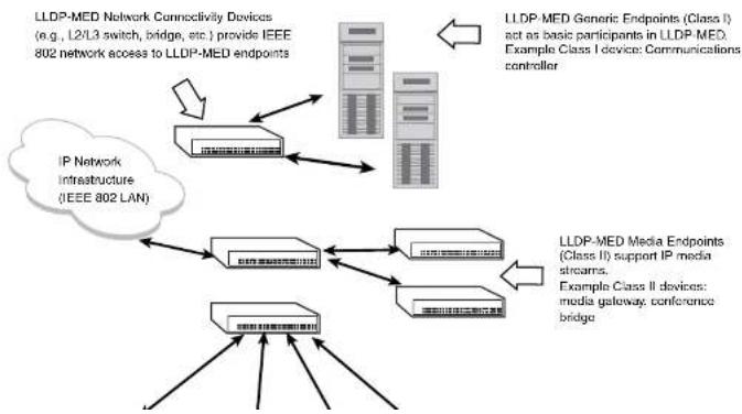
flowchart
graph TD
A["LLDP-MED Network Connectivity Devices (e.g., L2/L3 switch, bridge, etc.) provide IEEE 802 network access to LLDP-MED endpoints"] --> B["IP Network Infrastructure (IEEE 802 LAN)"]
C["LLDP-MED Generic Endpoints (Class I) act as basic participants in LLDP-MED. Example Class I device: Communications controller"] --> D["LLDP-MED Media Endpoints (Class II) support IP media streams. Example Class II devices: media gateway, conference bridge"]
B --> E["Cloud"]
D --> F["Cloud"]
E --> G["Server"]
F --> H["Server"]
G --> I["Server"]
H --> J["Server"]
I --> K["Server"]
J --> L["Server"]
K --> M["Server"]
L --> N["Server"]
M --> O["Server"]
N --> P["Server"]
O --> Q["Server"]
P --> R["Server"]
Q --> S["Server"]
R --> T["Server"]
S --> U["Server"]
T --> V["Server"]
U --> W["Server"]
V --> X["Server"]
W --> Y["Server"]
• Automatically deploys network policies, such as Layer 2 and Layer 3 QoS policies and Voice VLANs.
• Supports E-911 Emergency Call Services (ECS) for IP telephony
• Collects Endpoint inventory information
• Network troubleshooting
• Helps to detect improper network policy configuration
LLDP-MED class
An LLDP-MED class specifies an Endpoint type and its capabilities. An Endpoint can belong to one of three LLDP-MED class types:
- Class 1 (Generic endpoint) – A Class 1 Endpoint requires basic LLDP discovery services, but does not support IP media nor does it act as an end-user communication appliance. A Class 1 Endpoint can be an IP communications controller, other communication-related server, or other device requiring basic LLDP discovery services.
- Class 2 (Media endpoint) – A Class 2 Endpoint supports media streams and may or may not be associated with a particular end user. Device capabilities include media streaming, as well as all of the capabilities defined for Class 1 Endpoints. A Class 2 Endpoint can be a voice/media gateway, conference, bridge, media server, etc..
- Class 3 (Communication endpoint) – A Class 3 Endpoint supports end user IP communication. Capabilities include aspects related to end user devices, as well as all of the capabilities defined for Class 1 and Class 2 Endpoints. A Class 3 Endpoint can be an IP telephone, softphone (PC-based phone), or other communication device that directly supports the end user.
Discovery services defined in Class 3 include location identifier (ECS/E911) information and inventory management.
The LLDP-MED device class is advertised when LLDP-MED is enabled on a port.
Figure 116 illustrates LLDP-MED connectivity and supported LLDP-MED classes.
- Receive LLDP information only
Transmit mode
An LLDP agent sends LLDP packets to adjacent LLDP-enabled devices. The LLDP packets contain information about the transmitting device and port.
An LLDP agent initiates the transmission of LLDP packets whenever the transmit countdown timing counter expires, or whenever LLDP information has changed. When a transmit cycle is initiated, the LLDP manager extracts the MIB objects and formats this information into TLVs. The TLVs are inserted into an LLDPDU, addressing parameters are prepended to the LLDPDU, and the information is sent out LLDP-enabled ports to adjacent LLDP-enabled devices.
Receive mode
An LLDP agent receives LLDP packets from adjacent LLDP-enabled devices. The LLDP packets contain information about the transmitting device and port.
When an LLDP agent receives LLDP packets, it checks to ensure that the LLDPDUs contain the correct sequence of mandatory TLVs, then validates optional TLVs. If the LLDP agent detects any errors in the LLDPDUs and TLVs, it drops them in software. TLVs that are not recognized but do not contain basic formatting errors, are assumed to be valid and are assigned a temporary identification index and stored for future possible alter retrieval by network management. All validated TLVs are stored in the neighbor database.
LLDP packets
LLDP agents transmit information about a sending device/port in packets called LLDP Data Units (LLDPDUs). All the LLDP information to be communicated by a device is contained within a single 1500 byte packet. A device receiving LLDP packets is not permitted to combine information from multiple packets.
As shown in Figure 117, each LLDPDU has three mandatory TLVs, an End of LLDPDU TLV, plus optional TLVs as selected by network management.
FIGURE 417. UDDU-2013
TLV support
This section lists the LLDP and LLDP-MED TLV support.
LLDP TLVs
There are two types of LLDP TLVs, as specified in the IEEE 802.3AB standard:
- Basic management TLVs consist of both optional general system information TLVs as well as mandatory TLVs.
Mandatory TLVs cannot be manually configured. They are always the first three TLVs in the LLDPDU, and are part of the packet header.
General system information TLVs are optional in LLDP implementations and are defined by the Network Administrator.
Dell PowerConnect devices support the following Basic Management TLVs:
- Chassis ID (mandatory)
- Port ID (mandatory)
• Time to Live (mandatory) - Port description
- System name
- System description
- System capabilities
- Management address
• End of LLDPDU
- Organizationally-specific TLVs are optional in LLDP implementations and are defined and encoded by individual organizations or vendors. These TLVs include support for, but are not limited to, the IEEE 802.1 and 802.3 standards and the TIA-1057 standard.
Dell PowerConnect devices support the following Organizationally-specific TLVs:
• 802.1 organizationally-specific TLVs
- Location identification
• Extended power-via-MDI
Mandatory TLVs
When an LLDP agent transmits LLDP packets to other agents in the same 802 LAN segments, the following mandatory TLVs are always included:
- Chassis ID
- Port ID
• Time to Live (TTL)
This section describes the above TLVs in detail.
Chassis ID
The Chassis ID identifies the device that sent the LLDP packets.
There are several ways in which a device may be identified. A chassis ID subtype, included in the TLV and shown in Table 121, indicates how the device is being referenced in the Chassis ID field.
TABLE 121 Chassis ID subtypes
| ID subtype Description | ||||||
| 0 | R | e | s | e | r | v |
| 1 Chassis component | ||||||
| 2 | I | n | t | e | r | f |
| 3 | P | o | r | t | c | o |
| 4 | M | A | C | a | d | d |
| 5 | N | e | t | w | o | r |
| 6 | I | n | t | e | r | f |
| 7 Locally assigned | ||||||
8 - 255 Reserved
TABLE 122 Port ID subtypes
| ID subtype Description | ||||||
| 0 | R | o | s | c | r | v |
| 1 | I | n | t | e | r | f |
| 2 | P | o | r | t | c | o |
| 3 | M | A | C | a | d | d |
| 4 | N | c | t | w | o | r |
| 5 | I | n | t | c | r | f |
| 6 Agent circuit ID | ||||||
| 7 Locally assigned | ||||||
| 8 - 255 Reserved | ||||||
Dell PowerConnect devices use port ID subtype 3, the permanent MAC address associated with the port. Other third party devices may use a port ID subtype other than 3. The port ID appears similar to the following on the remote device, and in the CLI display output on the Dell PowerConnect device (show IIdp local-info).
Port ID (MAC address): 0012.f233.e2d3
The LLDPDU format is shown in "LLDPDU packet format" on page 688.
The Port ID TLV format is shown below.
FIGURE 118 Port ID TLV packet format
| TLV Type = 3 | TLV Information String Length = 2 | Time to Live (TTL) |
7 bits9 bits2 octets
TTL value
FIGURE 119 TTL TLV packet format
| TLV Type = 3 | TLV Information String Length = 2 | Time to Live (TTL) |
7 bits9 bits2 octets
MIB support
Dell PowerConnect devices support the following standard MIB modules:
- LLDP-MIB
- LLDP-EXT-DOT1-MIB
- LLDP-EXT-DOT3-MIB
- LLDP-EXT-MED-MIB
Syslog messages
Syslog messages for LLDP provide management applications with information related to MIB data consistency and general status. These Syslog messages correspond to the lldpRemTablesChange SNMP notifications. Refer to "Enabling LLDP SNMP notifications and syslog messages" on page 697.
Syslog messages for LLDP-MED provide management applications with information related to topology changes. These Syslog messages correspond to the lldpXMedTopologyChangeDetected SNMP notifications. Refer to "Enabling SNMP notifications and syslog messages for LLDP-MED topology changes" on page 708.
Configuring LLDP
TABLE 123 LLDP global configuration tasks and default behavior /value (Continued)
| Global task Default behavior / value when LLDP is enabled | |
| Enabling and disabling TLV advertisements When LLDP transmit is enabled, by default, the Dell PowerConnect device will automatically advertise LLDP capabilities, except for the system description, VLAN name, and power via MDI information, which may be configured by the system administrator. Also, if desired, you can disable the advertisement of individual TLVs. | |
| Changing the minimum time between LLDP transmissions | Automatically set to 2 seconds |
| Changing the interval between regular LLDP transmissions | Automatically set to 30 seconds |
| Changing the holdtime multiplier for transmit TTL Automatically set to 4 | |
| Changing the minimum time between port reinitializations | Automatically set to 2 seconds |
Configuration notes and considerations
- LLDP is supported on Ethernet interfaces only.
- If a port is 802.1X enabled, the transmission and reception of LLDP packets will only take place while the port is authorized.
- Cisco Discovery Protocol (CDP) and Brocade Discovery Protocol (FDP) run independently of LLDP. Therefore, these discovery protocols can run simultaneously on the same device.
- By default, the Dell PowerConnect device limits the number of neighbors per port to four, and staggers the transmission of LLDP packets on different ports, in order to minimize any high-usage spikes to the CPU.
- By default, the Dell PowerConnect device forwards
- Ports that are in blocking mode (spanning tree) can still receive LLDP packets from a forwarding port.
- A large model of the system indicates that the model is a combination of two sets for 000.
Enabling support for tagged LLDP packets
By default, Dell PowerConnect devices do not accept tagged LLDP packets from other vendors' devices. To enable support, apply the command lldp tagged-packets process at the Global CONFIG level of the CLI. When enabled, the device will accept incoming LLDP tagged packets if the VLAN tag matches any of the following:
• a configured VLAN on the port
• the default VLAN for a tagged port
- the configured untagged VLAN for a dual-mode port
To enable support for tagged LLDP packets, enter the following command.
PowerConnect(config)#lldp tagged-packets process
Syntax: [no] lldp tagged-packets process
Changing a port LLDP operating mode
LLDP packets are not exchanged until LLDP is enabled on a global basis. When LLDP is enabled on a global basis, by default, each port on the Dell device will be capable of transmitting and receiving LLDP packets. You can disable a port's ability to transmit and receive LLDP packets, or change the operating mode to one of the following:
• Transmit LLDP information only
- Receive LLDP information only
You can configure a different operating mode for each port on the Dell PowerConnect device. For example, you could disable the receipt and transmission of LLDP packets on port e 2/1, configure port e 2/3 to only receive LLDP packets, and configure port e 2/5 to only transmit LLDP packets.
The following sections show how to change the operating mode.
Enabling and disabling receive and transmit mode
To disable the receipt and transmission of LLDP packets on individual ports, enter a command such as the following at the Global CONFIG level of the CLI.
NOTE
When a port is configured to both receive and transmit LLDP packets and the MED capabilities TLV is enabled, LLDP-MED is enabled as well. LLDP-MED is not enabled if the operating mode is set to receive only or transmit only.
Enabling and disabling receive only mode
When LLDP is enabled on a global basis, by default, each port on the Dell PowerConnect device will be capable of transmitting and receiving LLDP packets. To change the LLDP operating mode from receive and transmit mode to receive only mode, simply disable the transmit mode. Enter a command such as the following at the Global CONFIG level of the CLI.
PowerConnect{config}#no l1dp enable transmit ports e 2/4 e 2/5 e 2/6
The above command changes the LLDP operating mode on ports 2/4, 2/5, and 2/6 from transmit and receive mode to receive only mode.
To change a port LLDP operating mode from transmit only to receive only, first disable the transmit only mode, then enable the receive only mode. Enter commands such as the following.
PowerConnect(config)#no lldp enable transmit ports e 2/7 e 2/8 e 2/9
PowerConnect{config}#1ldp enable receive ports e 2/7 e 2/8 e 2/9
The above commands change the LLDP operating mode on ports 2/7, 2/8, and 2/9, from transmit only to receive only. Note that if you do not disable the transmit only mode, you will configure the port to both transmit and receive LLDP packets.
NOTE
LLDP-MED is not enabled when you enable the receive only operating mode. To enable LLDP-MED, you must configure the port to both receive and transmit LLDP packets. Refer to "Enabling and disabling receive and transmit mode" on page 694.
Syntax: [no] lldp enable receive ports ethernet
Use the [no] form of the command to disable the receive only mode.
For
• PowerConnect B-Series FCX stackable switches -
PowerConnect(config)#no l1dp enable receive ports e 2/7 e 2/8
PowerConnect{config}#lldp enable transmit ports e 2/7 e 2/8
The above commands change the LLDP operating mode on ports 2/7 and 2/8 from receive only mode to transmit only mode. Any incoming LLDP packets will be dropped in software. Note that if you do not disable receive only mode, you will configure the port to both receive and transmit LLDP packets.
NOTE
LLDP-MED is not enabled when you enable the transmit only operating mode. To enable LLDP-MED, you must configure the port to both receive and transmit LLDP packets. Refer to "Enabling and disabling receive and transmit mode" on page 694.
Syntax: [no] lldp enable transmit ports ethernet
Use the [no] form of the command to disable the transmit only mode.
For
- PowerConnect B-Series FCX stackable switches -
Specifying the maximum number of LLDP neighbors
You can change the limit of the number of LLDP neighbors for which LLDP data will be retained, per device as well as per port.
Per device
You can change the maximum number of neighbors for which LLDP data will be retained for the entire system.
For example, to change the maximum number of LLDP neighbors for the entire device to 26, enter the following command.
PowerConnect(config)#lldp max-neighbors-per-port 5
Syntax: [no] lldp max-neighbors-per-port
Use the [no] form of the command to remove the static configuration and revert to the default value of four.
where
Use the show lldp command to view the configuration.
Enabling LLDP SNMP notifications and syslog messages
SNMP notifications and Syslog messages for LLDP provide management applications with information related to MIB data updates and general status.
When you enable LLDP SNMP notifications, corresponding Syslog messages are enabled as well. When you enable LLDP SNMP notifications, the device will send traps and corresponding Syslog messages whenever there are changes to the LLDP data received from neighboring devices.
LLDP SNMP notifications and corresponding Syslog messages are disabled by default. To enable them, enter a command such as the following at the Global CONFIG level of the CLI.
PowerConnect(config)#lldp enable snmp notifications ports e 4/2 to 4/6
The above command enables SNMP notifications and corresponding Syslog messages on ports 4/2 and 4/6. By default, the device will send no more than one SNMP notification and Syslog message within a five second period. If desired, you can change this interval. Refer to "Specifying the minimum time between SNMP traps and syslog messages" on page 697.
Syntax: [no] lldp enable snmp notifications ports ethernet
For
• PowerConnect B-Series FCX stackable switches -
You can list all of the ports individually, use the keyword to to specify ranges of ports, or a combination of both. To apply the configuration to all ports on the device, use the keyword all instead of listing the ports individually.
Syntax: [no] lldp snmp-notification-interval
where
Changing the minimum time between LLDP transmissions
The LLDP transmit delay timer limits the number of LLDP frames an LLDP agent can send within a specified time frame. When you enable LLDP, the system automatically sets the LLDP transmit delay timer to two seconds. If desired, you can change the default behavior from two seconds to a value between 1 and 8192 seconds.
NOTE
The LLDP transmit delay timer must not be greater than one quarter of the LLDP transmission interval (CLI command lldp transmit-interval).
The LLDP transmit delay timer prevents an LLDP agent from transmitting a series of successive LLDP frames during a short time period, when rapid changes occur in LLDP. It also increases the probability that multiple changes, rather than single changes, will be reported in each LLDP frame.
To change the LLDP transmit delay timer, enter a command such as the following at the Global CONFIG level of the CLI.
PowerConnect(config)#lldp transmit-delay 7
The above command causes the LLDP agent to wait a minimum of seven seconds after transmitting an LLDP frame and before sending another LLDP frame.
Syntax: [no] lldp transmit-delay
where
Changing the interval between regular LLDP transmissions
The LLDP transmit interval specifies the number of seconds between regular LLDP packet
transmissions. When you enable I DD by default, the devices will wait 20 seconds between regular
Changing the holdtime multiplier for transmit TTL
The holdtime multiplier for transmit TTL is used to compute the actual time-to-live (TTL) value used in an LLDP frame. The TTL value is the length of time the receiving device should maintain the information in its MIB. When you enable LLDP, the device automatically sets the holdtime multiplier for TTL to four. If desired, you can change the default behavior from four to a value between two and ten.
To compute the TTL value, the system multiplies the LLDP transmit interval by the holdtime multiplier. For example, if the LLDP transmit interval is 30 and the holdtime multiplier for TTL is 4, then the value 120 is encoded in the TTL field in the LLDP header.
To change the holdtime multiplier, enter a command such as the following at the Global CONFIG level of the CLI.
PowerConnect (config)411dp transmit-hold 6
Syntax: [no] lldp transmit-hold
where
NOTE
Setting the transmit interval or transmit holdtime multiplier, or both, to inappropriate values can cause the LLDP agent to transmit LLDPDUs with TTL values that are excessively high. This in turn can affect how long a receiving device will retain the information if it is not refreshed.
Changing the minimum time between port reinitializations
The LLDP re-initialization delay timer specifies the minimum number of seconds the device will wait from when LLDP is disabled on a port, until it will honor a request to re-enable LLDP on that port. When you enable LLDP, the system sets the re-initialization delay timer to two seconds. If desired, you can change the default behavior from two seconds to a value between one and ten seconds.
To set the re-initialization delay timer, enter a command such as the following at the Global CONFIG level of the CLI.
PowerConnect(config)#1ldp reinit-delay 5
- System name
802.1 capabilities:
• VLAN name (not automatically advertised)
- Untagged VLAN ID
802.3 capabilities:
- Link aggregation information
• MAC/PHY configuration and status
• Maximum frame size
• Power-via-MDI information (not automatically advertised)
The above TLVs are described in detail in the following sections.
NOTE
The system description, VLAN name, and power-via-MDI information TLVs are not automatically enabled. The following sections show how to enable these advertisements.
General system information
Except for the system description, the Dell PowerConnect device will advertise the following system information when LLDP is enabled on a global basis:
- Management address
- Port description
- System capabilities
• System description (not automatically advertised) - System name
Management Address
A management address is normally an IPv4 or IPv6 address that can be used to manage the device. Management address advertising has two modes: default, or explicitly configured. The default mode is used when no addresses are configured to be advertised for a given port. If any
- Other interface
For IPv6 addresses, link-local and anycast addresses will be excluded from these searches.
If no IP address is configured on any of the above, the port's current MAC address will be advertised.
To advertise a IPv4 management address, enter a command such as the following:
PowerConnect(config)#lldp advertise management-address ipv4 209.157.2.1 ports e 1/4
The management address will appear similar to the following on the remote device, and in the CLI display output on the PowerConnect device (show lldp local-info):
Management address (TPv4): 209.157.2.1
Syntax: [no] lldp advertise management-address ipv4
To support an IPv6 management address, there is a similar command that has equivalent behavior as the IPv4 command.
To advertise an IPv6 management address, enter a command such as the following:
PowerConnect(config)#lldp advertise management-address ipv6 1234:5678::90 ports c 2/7
Syntax: [no] lldp advertise management-address ipv6
For
You can list all of the ports individually, use the keyword to to specify ranges of ports, or a combination of both. To apply the configuration to all ports on the device, use the keyword all instead of listing the ports individually. Note that using the keyword all may cause undesirable effects on some ports. For example, if you configure all ports to advertise their VLAN name, and the configuration includes ports that are not members of any VLAN, the system will warn of the misconfigurations on non-member VLAN ports. The configuration will be applied to all ports, however, the ports that are not members of any VLAN will not send VLAN name advertisements.
System capabilities
The system capabilities TLV identifies the primary functions of the device and indicates whether these primary functions are enabled. The primary functions can be one or more of the following (more than one for example, if the device is both a bridge and a router):
- Repeater
- Bridge
- WLAN access point
- Router
- Telephone
• DOCSIS cable device
• Station only (devices that implement end station capability) - Other
System capabilities for Dell PowerConnect devices are based on the type of software image in use (e.g., Layer 2 switch or Layer 3 router). The enabled capabilities will be the same as the available capabilities, except that when using a router image (base or full Layer 3), if the global route-only feature is turned on, the bridge capability will not be included, since no bridging takes place.
By default, the system capabilities are automatically advertised when LLDP is enabled on a global basis. To disable this advertisement, enter a command such as the following.
PowerConnect{config}#no lldp advertise system-capabilities ports e 2/4 to 2/12
The system capabilities will appear similar to the following on the remote device, and in the CLI display output on the Dell PowerConnect device (show lldp local-Info).
System description
The system description is the network entity, which can include information such as the product name or model number, the version of the system hardware type, the software operating system level, and the networking software version. The information corresponds to the sysDescr MIB object in MIB-II.
To advertise the system description, enter a command such as the following.
PowerConnect(config)#11dp advertise system-description ports e 2/4 to 2/12
The system description will appear similar to the following on the remote device, and in the CLI display output on the Dell PowerConnect device (show lldp local-info).
System description : "Brocade Communications, Inc., IronWare Version 04.0.00b25&T3cl Compiled on Sep 04 2007 at 0\
3:54:29 labeled as SX504000b256"
NOTE
The contents of the show command output will vary depending on which TLVs are configured to be advertised.
Syntax: [no] lldp advertise system-description ports ethernet
For
• PowerConnect B-Series FCX stackable switches -
You can list all of the ports individually, use the keyword to to specify ranges of ports, or a combination of both. To apply the configuration to all ports on the device, use the keyword all instead of listing the ports individually. Note that using the keyword all may cause undesirable effects on some ports. For example, if you configure all ports to advertise their VLAN name, and the configuration includes ports that are not members of any VLAN, the system will warn of the misconfigurations on non-member VLAN ports. The configuration will be applied to all ports, however, the ports that are not members of any VLAN will not send VLAN name advertisements.
System name
The system name is the system administratively assigned name, taken from the sysName MIB object in MIR-II. The sysName MIR object corresponds to the name defined with the CI I command
You can list all of the ports individually, use the keyword to to specify ranges of ports, or a combination of both. To apply the configuration to all ports on the device, use the keyword all instead of listing the ports individually. Note that using the keyword all may cause undesirable effects on some ports. For example, if you configure all ports to advertise their VLAN name, and the configuration includes ports that are not members of any VLAN, the system will warn of the misconfigurations on non-member VLAN ports. The configuration will be applied to all ports, however, the ports that are not members of any VLAN will not send VLAN name advertisements.
802.1 capabilities
Except for the VLAN name, the Dell PowerConnect device will advertise the following 802.1 attributes when LLDP is enabled on a global basis:
• VLAN name (not automatically advertised)
- Untagged VLAN ID
VLAN name
The VLAN name TLV contains the name and VLAN ID of a VLAN configured on a port. An LLDPDU may include multiple instances of this TLV, each for a different VLAN.
To advertise the VLAN name, enter a command such as the following.
PowerConnect(config)#lldp advertise vlan-name vlan 99 ports e 2/4 to 2/12
The VLAN name will appear similar to the following on the remote device, and in the CLI display output on the Dell PowerConnect device (show lldp local-info).
VLAN name (VLAN 99): "Voice-VLAN-99"
Syntax: [no] lldp advertise vlan-name vlan
For
For
- PowerConnect B-Series FCX stackable switches -
Syntax: [no] lldp advertise port-vlan-id ports ethernet
For
PowerConnect B-Series FCX stackable switches -
You can list all of the ports individually, use the keyword to to specify ranges of ports, or a combination of both. To apply the configuration to all ports on the device, use the keyword all instead of listing the ports individually. Note that using the keyword all may cause undesirable effects on some ports. For example, if you configure all ports to advertise their VLAN name, and the configuration includes ports that are not members of any VLAN, the system will warn of the misconfigurations on non-member VLAN ports. The configuration will be applied to all ports, however, the ports that are not members of any VLAN will not send VLAN name advertisements.
802.3 capabilities
Except for Power-via-MDI information, the Dell PowerConnect device will advertise the following 802.3 attributes when LLDP is enabled on a global basis:
- Link aggregation information
• MAC/PHY configuration and status
• Maximum frame size
• Power-via-MDI information (not automatically advertised)
Link aggregation
The link-aggregation TLV indicates the following:
• Whether the link is capable of being aggregated
• Whether the link is currently aggregated
• The primary trunk port
Dell PowerConnect devices advertise link aggregation information about standard link aggregation (LACP) as well as static trunk configuration.
By default, link-aggregation information is automatically advertised when LLDP is enabled on a global basis. To disable this advertisement, enter a command such as the following:
MAC/PHY configuration status
The MAC/PHY configuration and status TLV includes the following information:
• Auto-negotiation capability and status
• Speed and duplex mode
- Flow control capabilities for auto-negotiation
• Port speed down-shift and maximum port speed advertisement
- If applicable, indicates if the above settings are the result of auto-negotiation during link initiation or of a manual set override action
The advertisement reflects the effects of the following CLI commands:
- speed-duplex
- flow-control
- gig-default
- link-config
By default, the MAC/PHY configuration and status information are automatically advertised when LLDP is enabled on a global basis. To disable this advertisement, enter a command such as the following.
PowerConnect(config)#no 11dp advertise mac-phy-config-status ports e 2/4 to 2/12
The MAC/PHY configuration advertisement will appear similar to the following on the remote device, and in the CLI display output on the Dell PowerConnect device (show lldp local-info).
+ 802.3 MAC/PHY : auto-negotiation enabled
Advertised capabilities: 10baseT-HD, 10baseT-FD, 100baseTX-HD, 100baseTX-FD,
fdxGFase, fdxDBase, 1000baseT-HD, 1000baseT-FD
Operational MAU type: 100BaseTX-FD
Syntax: [no] lldp advertise mac-phy-config-status ports ethernet
For
• PowerConnect B-Series FCX stackable switches -
The maximum frame size advertisement will appear similar to the following on the remote device, and in the CLI display output on the Dell PowerConnect device (show lldp local-info).
Maximum frame size: 1522 octets
Syntax: [no] lldp advertise max-frame-size ports ethernet
For
- PowerConnect B-Series FCX stackable switches -
Configuring LLDP-MED
This section provides the details for configuring LLDP-MED.
Table 124 lists the global and interface-level tasks and the default behavior/value for each task.
TABLE 124 LLDP-MED configuration tasks and default behavior / value
| Task Default behavior / value | |
| Global CONFIG-level tasks | |
| Enabling LLDP-MED on a global basis Disabled | |
| Enabling SNMP notifications and Syslog messages | Disabled |
| for LLDP-MED topology change | |
Changing the Fast Start Repeat Count The system automatically sets the fast start repeat count to 3 when a Network Connectivity Device receives an LLDP
NOTE
LLDP-MED is not enabled on ports where the LLDP operating mode is receive only or transmit only. LLDP-MED is enabled on ports that are configured to both receive and transmit LLDP packets and have the LLDP-MED capabilities TLV enabled.
Enabling SNMP notifications and syslog messages for LLDP-MED topology changes
SNMP notifications and Syslog messages for LLDP-MED provide management applications with information related to topology changes. For example, SNMP notifications can alert the system whenever a remote Endpoint device is connected to or removed from a local port. SNMP notifications identify the local port where the topology change occurred, as well as the device capability of the remote Endpoint device that was connected to or removed from the port.
When you enable LLDP-MED SNMP notifications, corresponding Syslog messages are enabled as well. When you enable LLDP-MED SNMP notifications, the device will send traps and Syslog messages when an LLDP-MED Endpoint neighbor entry is added or removed.
SNMP notifications and corresponding Syslog messages are disabled by default. To enable them, enter a command such as the following at the Global CONFIG level of the CLI.
PowerConnect(config)#lldp enable smp med-topo-change-notifications ports e 4/4 to 4/6
Syntax: [no] lldp enable snmp med-topo-change-notifications ports ethernet
• PowerConnect B-Series FCX stackable switches -
You can list all of the ports individually, use the keyword to to specify ranges of ports, or a combination of both. To apply the configuration to all ports on the device, use the keyword all instead of listing the ports individually. Note that using the keyword all may cause undesirable effects on some ports. For example, if you configure all ports to advertise their VLAN name, and the configuration includes ports that are not members of any VLAN, the system will warn of the misconfigurations on non-member VLAN ports. The configuration will be applied to all ports,
NOTE
The LLDP-MED fast start mechanism is only intended to run on links between Network Connectivity devices and Endpoint devices. It does not apply to links between LAN infrastructure elements, including between Network Connectivity devices, or to other types of links.
To change the LLDP-MED fast start repeat count, enter commands such as the following.
PowerConnect(config)#lldp med fast-start-repeat-count 5
The above command causes the device to send five LLDP packets during the LLDP-MED fast start period.
Syntax: [no] lldp med fast-start-repeat-count
where value is a number from 1 to 10, which specifies the number of packets that will be sent during the LLDP-MED fast start period. The default is 3.
Defining a location id
The LLDP-MED Location Identification extension enables the Dell PowerConnect device to set the physical location that an attached Class III Endpoint will use for location-based applications. This feature is important for applications such as IP telephony, for example, where emergency responders need to quickly determine the physical location of a user in North America that has just dialed 911.
For each port, you can define one or more of the following location ID formats:
- Geographic location (coordinate-based)
- Civic address
• Emergency Call Services (ECS) Emergency Location Identification Number (ELIN)
The above location ID formats are defined in the following sections.
Coordinate-based location
Coordinate-based location is based on the IETF RFC 3825 [6] standard, which specifies a Dynamic
- Let A be a prime f_out and let B be a prime f_out . Then, if A is a prime f_out , then
latitude < degrees> is the angular distance north or south from the earth equator measured through 90 degrees. Positive numbers indicate a location north of the equator and negative numbers indicate a location south of the equator.
resolution
longitude
resolution
altitude floors
resolution
altitude meters
resolution
- wgs84 – (geographical 3D) – World Geodesic System 1984, CRS Code 4327, Prime Meridian Name: Greenwich
- nad83-navd88 – North American Datum 1983, CRS Code 4269, Prime Meridian Name: Greenwich; The associated vertical datum is the North American Vertical Datum of 1988 (NAV088). Use this datum when referring locations on land. If land is near tidal water use
• Latitude is 41.87884 degrees north (or 41.87884 degrees).
• Longitude is 87.63602 degrees west (or 87.63602 degrees).
- The latitude and longitude resolution of 18 describes a geo-location area that is latitude 41.8769531 to latitude 41.8789062 and extends from -87.6367188 to -87.6347657 degrees longitude. This is an area of approximately 373412 square feet (713.3 ft. x 523.5 ft.).
- The location is inside a structure, on the 103rd floor.
• The WGS 84 map was used as the basis for calculating the location.
Example coordinate-based location advertisement
The coordinate-based location advertisement will appear similar to the following on the remote device, and in the CLI display output on the Dell PowerConnect device (show lldp local-info).
+ MED Location ID
Data Format: Coordinate-based
Latitude Resolution : 20 bits
Latitude Value : -78.303 degrees
Longitude Resolution : 18 bits
Longitude Value : 34.27 degrees
Altitude Resolution : 16 bits
Altitude Value : 50. motors
Datum : WGS B4
Civic address location
When you configure a media Endpoint location using the address-based location, you specify the location the entry refers to, the country code, and the elements that describe the civic or postal address.
To configure a civic address-based location for LLDP-MED, enter commands such as the following at the Global CONFIG level of the CLI.
PowerConnect(config)#ldp med location-id civic-address refers-to client country US elem 1 CA elem 3 "Santa Clara" elem 6 "4980 Great America Pkwy" elem 24 55054 elom 27 5 elom 28 551 elom 29 office elom 23 "John Doe"
- KR - Korea
• US - United States
NOTE
If the value of an element contains one or more spaces, use double quotation marks (*) at the beginning and end of the string. For example, elem 3 "Santa Clara".
TABLE 125 Elements used with civic address
| Civic Address (CA) Description Acceptable values / examples type | |
| 0 Language The ISO 639 language code used for presenting the address information. | |
| 1 National subdivisions (state, canton, region, province, or prefecture) | Examples:Canada - ProvinceGermany - StateJapan - MetropolisKorea - ProvinceUnited States - State |
| 2 County, parish, gun (JP), or district (IN) | Examples:Canada - CountyGermany - CountyJapan - City or rural areaKorea - CountyUnited States - County |
| 3 City, township, or shi (JP) Examples: | |
| Canada - City or townGermany - CityJapan - Ward or village | |
TABLE 125 Elements used with civic address (Continued)
| Civic Address (CA) type | Description | Acceptable values / examples | ||||
| 6 | S | t | r | c | c | t |
| Canada - StreetGermany - StreetJapan - BlockKorea - StreetUnited States - Street | ||||||
| 16 Loading street direction N (north), E (east), S (south), W (west), NE, NW, SE, SW | ||||||
| 17 Trailing street suffix N (north), E (east), S (south), W (west), NE, NW, SE, SW | ||||||
| 18 Street suffix Acceptable values for the United States are listed in the United States Postal Service Publication 28 [18], Appendix C.Example: Ave, Place | ||||||
| 19 House number The house number (street address)Example: 1234 | ||||||
| 20 House number suffix A modifier to the house number. It does not include parts of the house number.Example: A, 1/2 | ||||||
| 21 Landmark or vanity address A string name for a location. It conveys a common local designation of a structure, a group of buildings, or a place that helps to locate the place.Example: UC Berkeley | ||||||
| 22 Additional location information | An unstructured string name that conveys additional information about the location.Example: west wing | |||||
| 23 Name (residence and office occupant) | Identifies the person or organization associated with the address.Example: Textures Beauty Salon | |||||
| 24 Postal / zip code The valid postal / zip code for the address.Example: 95054-1234 | ||||||
TABLE 125 Elements used with civic address (Continued)
| Civic Address (CA) type | Description Acceptable values / examples | |
| 30 | Postal community name | When the postal community name is defined, the civic community name (typically CA type 3) is replaced by this value.Example: Alviso |
| 31 Post office box (P.O. box) When a P.O. box is defined, the street address components (CA types 6, 16, 17, 18, 19, and 20) are replaced with this value.Example: P.O. Box 1234 | ||
| 32 Additional code An additional country-specific code that identifies the location.For example, for Japan, this is the Japan Industry Standard (JIS) address code. The JIS address code provides a unique address Inside of Japan, down to the level of indicating the floor of the building. | ||
| 128 Script The script (from ISO 15924 [14]) used to present the address information.Example: LatnNOTE: If not manually configured, the system assigns the default value Latn | ||
| 255 Reserved | ||
Example civic address location advertisement
The Civic address location advertisement will appear similar to the following on the remote device, and in the CLI display output on the Dell PowerConnect device (show lldp local-info).
+ MED Location ID
Data Format: Civic Address
Location of: Client
Country : "US"
CA Type : 1
CA Value : "CA"
CA Type : 3
CA Value : "Santa Clara"
CA Type : 6
When you configure a media Endpoint location using the emergency call services location, you specify the Emergency Location Identification Number (ELIN) from the North America Numbering Plan format, supplied to the Public Safety Answering Point (PSAP) for ECS purposes.
To configure an ECS-based location for LLDP-MED, enter a command such as the following at the Global CONFIG level of the CLI.
PowerConnect(config)#lldp med location-id eos-elin 4082071700
Syntax: [no] lldp med location-id ecs-elin
For
- PowerConnect B-Series FCX stackable switches -
Example ECS ELIN location advertisements
The ECS ELIN location advertisement will appear similar to the following on the remote device, and in the CLI display output on the Dell PowerConnect device (show lldp local-info).
+ MED Location ID
Data Format: ECS ELIN
Value : 4082071700
Defining an LLDP-MED network policy
An LLDP-MED network policy defines an Endpoint VLAN configuration (VLAN type and VLAN ID) and associated Layer 2 and Layer 3 priorities that apply to a specific set of applications on a port.
NOTE
This feature applies to applications that have specific real-time network policy requirements, such as interactive voice or video services. It is not intended to run on links other than between Network
NOTE
Endpoints will advertise a policy as "unknown" in the show lldp neighbor detail command output, if it is a policy that is required by the Endpoint and the Endpoint has not yet received it.
Configuration syntax
The CLI syntax for defining an LLDP-MED network policy differs for tagged, untagged, and priority tagged traffic. Refer to the appropriate syntax, below.
For tagged traffic
Syntax: [no] lldp med network-policy application
For untagged traffic
Syntax: [no] lldp med network-policy application
For priority-tagged traffic
Syntax: [no] lldp med network-policy application
For
• PowerConnect B-Series FCX stackable switches -
You can list all of the ports individually, use the keyword to to specify ranges of ports, or a combination of both. To apply the configuration to all ports on the device, use the keyword all instead of listing the ports individually.
- guest-voice – Limited voice service for guest users and visitors with their own IP telephony handsets or similar devices that support interactive voice services.
-
guest-voice-signaling – Limited voice service for use in network topologies that require a
-
voice – For use by dedicated IP telephony handsets and similar devices that support interactive voice services.
- voice-signaling – For use in network topologies that require a different policy for voice signaling than for voice media. Note that this application type should not be advertised if all the same network policies apply as those advertised in the voice policy TLV.
- tagged vlan
specifies the tagged VLAN that the specified application type will use. - untagged indicates that the device is using an untagged frame format.
- priority-tagged indicates that the device uses priority-tagged frames. In this case, the device uses the default VLAN (PVID) of the ingress port.
- priority <0 - 7> indicates the Layer 2 priority value to be used for the specified application type. Enter 0 to use the default priority.
- dscp <0 - 63> specifies the Layer 3 Differentiated Service codepoint priority value to be used for the specified application type. Enter 0 to use the default priority.
For
• PowerConnect B-Series FCX stackable switches -
You can list all of the ports individually, use the keyword to to specify ranges of ports, or a combination of both. To apply the configuration to all ports on the device, use the keyword all instead of listing the ports individually. Note that using the keyword all may cause undesirable effects on some ports. For example, if you configure all ports to advertise their VLAN name, and the configuration includes ports that are not members of any VLAN, the system will warn of the misconfigurations on non-member VLAN ports. The configuration will be applied to all ports, however, the ports that are not members of any VLAN will not send VLAN name advertisements.
LLDP-MED attributes advertised by the Dell PowerConnect device
LLDP-MED attributes are only advertised on a port if LLDP-MED is enabled (which is done by enabling the LLDP-MED capabilities TLV), the port operating mode is receive and transmit (the default), and the port has received an LLDP-MED advertisement from an Endpoint. By default, the Dell PowerConnect device will automatically advertise the following LLDP-MED attributes when the above criteria are met:
• The device type (Network Connectivity device or Endpoint (Class 1, 2, or 3))
By default, LLDP-MED information is automatically advertised when LLDP-MED is enabled. To disable this advertisement, enter a command such as the following.
PowerConnect(config)#no lldp advertise med-capabilities ports e 2/4 to 2/12
NOTE
Disabling the LLDP-MED capabilities TLV disables LLDP-MED.
To re-enable the LLDP-MED Capabilities TLV (and LLDP-MED) after it has been disabled, enter a command such as the following.
PowerConnect(config)#lldp advertise med-capabilities ports e 2/4 to 2/12
The LLDP-MED capabilities advertisement will appear similar to the following on the remote device, and in the CLI display output on the Dell PowerConnect device (show lldp local-info).
+ MED capabilities: capabilities, networkPolicy, location, extendedPSE MED device type : Network Connectivity
Syntax: [no] lldp advertise med-capabilities ports ethernet
For
• PowerConnect B-Series FCX stackable switches -
You can list all of the ports individually, use the keyword to to specify ranges of ports, or a combination of both. To apply the configuration to all ports on the device, use the keyword all instead of listing the ports individually. Note that using the keyword all may cause undesirable effects on some ports. For example, if you configure all ports to advertise their VLAN name, and the configuration includes ports that are not members of any VLAN, the system will warn of the misconfigurations on non-member VLAN ports. The configuration will be applied to all ports, however, the ports that are not members of any VLAN will not send VLAN name advertisements.
Displaying LLDP statistics and configuration settings
You can use the following CLI show commands to display information about LLDP settings and
PowerConnect#show 11dp
LLDF transmit interval : 10 seconds
LLDP transmit hold multiplier : 4 (transmit TTL: 40 seconds)
LLDP transmit delay : 1 seconds
LLDF SNMP notification interval : 5 seconds
LLDP reinitialize delay : 1 seconds
LLDF-MED fast start repeat count : 3
LLDP maximum neighbors : 392
LLDF maximum neighbors per port : 4
Syntax: show lldp
The following table describes the information displayed by the show lldp statistics command.
This field... Displays...
| LLDP transmit interval The number of seconds between regular LLDP packet transmissions. | |
| LLDP transmit hold multiplier | The multiplier used to compute the actual time-to-live (TTL) value of an LLDP advertisement. The TTL value is the transmit interval multiplied by the transmit hold multiplier. |
| LLDP transmit delay | The number of seconds the LLDP agent will wait after transmitting an LLDP frame and before transmitting another LLDP frame. |
| LLDP SNMP notification interval | The number of seconds between transmission of SNMP LLDP traps (lldpRemTablesChange) and SNMP LLDP-MED traps (lldpXMedTopologyChangeDetected). |
| LLDP reinitialize delay | The minimum number of seconds the device will wait from when LLDP is disabled on a port, until a request to re-enable LLDP on that port will be honored. |
| LLDP MED fast start repeat count | The number of seconds between LLDP frame transmissions when an LLDP MED Endpoint is nowly detected. |
| LLDP maximum neighbors | The maximum number of LLDP neighbors for which LLDP data will be retained, per device. |
| LLDP maximum neighbors per port | The maximum number of LLDP neighbors for which LLDP data will be retained, per port. |
PowerConnect#show lldp statistics
Last neighbor change time: 23 hours 50 minutes 40 seconds ago
| Neighbor entries added | : 14 |
| Neighbor entries deleted | : 5 |
| Neighbor entries aged out | : 4 |
| Neighbor advertisements dropped | : 0 |
| Port | Tx Pkts | Rx Pkts | Rx Pkts | Rx Pkts | Rx TLVs | Rx TLVs | Neighbors |
| Total | Total | w/Errors | Discarded | Unrecognz | Discarded | Aged Out | |
| 1 | 60963 | 75179 | 0 | 0 | 0 | 0 | 4 |
| 2 | 0 | 0 | 0 | 0 | 0 | 0 | 0 |
| 3 | 60963 | 60863 | 0 | 0 | 0 | 0 | 0 |
| 4 | 60963 | 121925 | 0 | 0 | 0 | 0 | 0 |
| 5 | 0 | 0 | 0 | 0 | 0 | 0 | 0 |
| 6 | 0 | 0 | 0 | 0 | 0 | 0 | 0 |
| 7 | 0 | 0 | 0 | 0 | 0 | 0 | 0 |
| 8 | 0 | 0 | 0 | 0 | 0 | 0 | 0 |
| 9 | 0 | 0 | 0 | 0 | 0 | 0 | 0 |
| 10 | 60974 | 0 | 0 | 0 | 0 | 0 | 0 |
| 11 | 0 | 0 | 0 | 0 | 0 | 0 | 0 |
| 12 | 0 | 0 | 0 | 0 | 0 | 0 | 0 |
| 13 | 0 | 0 | 0 | 0 | 0 | 0 | 0 |
| 14 | 0 | 0 | 0 | 0 | 0 | 0 | 0 |
Syntax: show lldp statistics
NOTE
You can reset LLDP statistics using the CLI command clear LLDP statistics. Refer to "Resetting LLDP statistics" on page 725.
The following table describes the information displayed by the show lldp statistics command.
This field... Displays...
Last neighbor change time
The elapsed time (in hours, minutes, and seconds) since a neighbor last advertised information. For example, the elapsed time since a neighbor was last added, deleted, or its advertised information changed.
This field... Displays...
| Rx Pkts w/Errors The number of LLDP packets the port received that have one or more detectable errors. |
| Rx Pkts Discarded The number of LLDP packets the port received then discarded. |
| Rx TLVs Unrecognz The number of TLVs the port received that were not recognized by the LLDP local agent.Unrecognized TLVs are retained by the system and can be viewed in the output of the show LLDP neighbors detail command or retrieved through SNMP. |
| Rx TLVs Discarded The number of TLVs the port received then discarded. |
| Neighbors Aged Out The number of times a neighbor information was deleted because its TTL timer expired. |
LLDP neighbors
The show lldp neighbors command displays a list of the current LLDP neighbors per port.
The following shows an example report.
PowerConnect#show lldp neighbors
| Lcl Port | Chassis ID | Port ID | Port Description | System Name |
| 1 | 0004.1234.0fc0 | 0004.1234.0fc0 | GigabitEthernet9/1 | FastIron Supo- |
| 1 | 00e0.5201.4000 | 00e0.5201.4000 | GigabitEthernet0/1/1 | PCX624XGP Swi- |
| 3 | 00e0.5211.0200 | 00e0.5211.0203 | GigabitEthernet4 | FESX424+2XG S- |
| 4 | 00e0.5211.0200 | 00e0.5211.0202 | GigabitEthernet3 | FESX424+2XG S- |
| 4 | 00e0.5211.0200 | 00e0.5211.0210 | GigabitEthernet17 | FESX424+2XG S- |
| 15 | 00e0.5211.0200 | 00e0.5211.0205 | GigabitEthernet16 | FESX424+2XG S- |
| 16 | 00e0.5211.0200 | 00e0.5211.020e | GigabitEthernet15 | FESX424+2XG S- |
| 17 | 00e0.5211.0200 | 00e0.5211.0211 | GigabitEthernet18 | FESX424+2XG S- |
| 18 | 00e0.5211.0200 | 00e0.5211.0210 | GigabitEthernet17 | FESX424+2XG S- |
Syntax: show lldp neighbors
The following table describes the information displayed by the show lldp neighbors command.
This field... Displays...
Lcl Port The local LLDP port number.
LLDP neighbors detail
The show lldp neighbors detail command displays the LLDP advertisements received from LLDP
neighbors.
The following shows an example show lldp neighbors detail report.
NOTE
The show lldp neighbors detail output will vary depending on the data received. Also, values that are not recognized or do not have a recognizable format, may be displayed in hexadecimal binary
form.
PowerConnect↓show 11dp neighbors detail parts e 1/9
Local port: 1/9
Neighbor: 0800.0f18.cc03, TTL 101 seconds
+ Chassis ID (network address): 10.43.39.151
+ Port ID (MAC address): 0800.0f18.cc03
+ Time to live: 120 seconds
+ Port description : "LAN port"
+ System name : "regDN 1015, MITEL 5235 DM"
+ System description : "regDN 1015, MITEL 5235 DM, h/w rev 2, ASIC rev 1, f/w"
Boot 02.01.00.11, f/w Main 02.01.00.11"
+ System capabilities : bridge, telephone
Enabled capabilities: bridge, telephone
+ Management address (IPv4): 10.43.39.151
- 802.3 MAC/PEY : auto-negotiation enabled
Advertised capabilities: 10BaseT-HD, 10BaseT-FD, 100BaseTX-HD,
100BaseTX-FD
Operational MAU type : 100BaseTX-FD
+ MED capabilities: capabilities, networkPolicy, extendedPD
MED device type : Endpoint Class III
+ MED Network Policy
Application Type : Voice
Policy Flags : Known Policy, Tagged
VLAN ID : 300
L2 Priority
DSCP Value : 7
- MTR: Enhanced Driver vs. MTR
This field... Displays...
Neighbor The source MAC address from which the packet was received, and the remaining TTL for the neighbor entry.
Syntax: show lldp neighbors detail [ports ethernet
If you do not specify any ports or use the keyword all, by default, the report will show the LLDP neighbor details for all ports.
For
• PowerConnect B-Series FCX stackable switches -
You can list all of the ports individually, use the keyword to to specify ranges of ports, or a combination of both. To apply the configuration to all ports on the device, use the keyword all instead of listing the ports individually.
LLDP configuration details
The show lldp local-info command displays the local information advertisements (TLVs) that will be transmitted by the LLDP agent.
NOTE
The show lldp local-info output will vary based on LLDP configuration settings.
The following shows an example report.
PowerConnect#show lldp local-info ports e 20 Local port: 20
+ Chassis ID (MAC address): 0012.f233.e2c0
+ Port ID (MAC address): 0012.f233.e2d3
+ Time to live: 40 seconds
+ System name: "PowerConnect"
+ Port description: "GigabitEthernet2D"
+ System description : "Brocade Communications, Inc. IronWare V\ersion 04.0.00b256T3e1 Compiled on Sep 04 2007 at 0\3:54:29 labeled as SXS04000b256"
Application Type : Video Conferencing
Policy Flags : Known Policy, Tagged
VLAN TD : 10
E2 TITOLOGY : 5 DSCR Value : 10
+ MED Location ID
Data Format: Coordinate-based location
Latitude Resolution : 20 bits
Latitude Value : -78.303 degrees
Longitude Resolution: 15 bits Longitude Value: 34.07 degrees
Longitudos Values : 34,27 degrees
31 + i + u + m 10 m : 50 mol/sec
Datum : WCS 84
+ MED Location ID
Data Format: Civic Address
Location of: Client
Country : "US"
CA Type :
CA Value : "CA"
CA Type :
CA Value : "Santa Clara"
CA Type
CA Value : "4980 Great America Pkwy."
CA Type :
CA value : "95054"
CA Type :
CA Value : "5"
CA Type : 28
CA Value : "551"
CA TYPE : 29
CA Value : "office"
CA Type : 23
CA Value : "John Doe"
+ MED Location ID
Data Format: ECS ELIN
Value : "1234567890"
+ MED Extended Power via MDI
Power Type : PSE device
• PowerConnect B-Series FCX stackable switches -
You can list all of the ports individually, use the keyword to to specify ranges of ports, or a combination of both. To apply the configuration to all ports on the device, use the keyword all instead of listing the ports individually.
Resetting LLDP statistics
To reset LLDP statistics, enter the clear lldp statistics command at the Global CONFIG level of the CLI. The Dell PowerConnect device will clear the global and per-port LLDP neighbor statistics on the device (refer to "LLDP statistics" on page 719).
PowerConnect #clear lldp statistics
Syntax: clear lldp statistics [ports ethernet
If you do not specify any ports or use the keyword all, by default, the system will clear lldp statistics on all ports.
For
• PowerConnect B-Series FCX stackable switches -
You can list all of the ports individually, use the keyword to to specify ranges of ports, or a combination of both. To apply the configuration to all ports on the device, use the keyword all instead of listing the ports individually.
Clearing cached LLDP neighbor information
The Dell PowerConnect device clears cached LLDP neighbor information after a port becomes disabled and the LLDP neighbor information ages out. However, if a port is disabled then re-enabled before the neighbor information ages out, the device will clear the cached LLDP neighbor information when the port is re-enabled.
If desired, you can manually clear the cache. For example, to clear the cached LLDP neighbor information for port e 20, enter the following command at the Global CONFIG level of the CI.
Configuring IP Multicast Protocols
Chapter
25
Table 126 lists the individual Dell PowerConnect switches and the IP multicast features they support. These features are supported in the full Layer 3 software image only.
TABLE 126 Supported IP multicast features
| Feature PowerConnect B-Series FCX | |
| Internet Group Management Protocol (IGMP) V1, V2, and V3 (for multicast routing scenarios) | Yes |
| IGMPv3 fast leave (for routing) Yes | |
| Protocol Independent Multicast Dense mode (PIM-DM) V1 (draft-ictf-pim-dm-05) and V2 (draft-ictf-pim-v2 dm-03) | Yes |
| Protocol Independent Multicast Sparse mode (PIM-SM) V2 (RFC 2362) | Yes |
| PIM passive Yes | |
| IGMP proxy Yes | |
| Passive multicast route insertion (PMRI) Yes | |
| IP multicast and IGMP snooping on the same device | Yes |
| ACLs to control multicast features Yes | |
| Static multicast groups Yes | |
This chapter describes how to configure Layer 3 Switches for Protocol Independent Multicast (PIM).
IPv4 multicast group addresses
In IPv4 Multicast, host groups are identified by Class D addresses, i.e., those with "1110" as their higher-order four bits. In Internet standard "dotted decimal" notation, these group addresses range from 224.0.0.0 to 239.255.255.255. However, the IANA IPv4 Multicast Address Registry (referencing RFC 3171) stipulates that the range 224.0.0.0 through 224.0.0.255 should not be used for regular multicasting applications.
"The range of addresses between 224.0.0.0 and 224.0.0.255, inclusive, is reserved for the use of routing protocols and other low-level topology discovery or maintenance protocols, such as gateway discovery and group membership reporting. Multicast routers should not forward any multicast datagram with destination addresses in this range, regardless of its TTL."
Mapping of IPv4 Multicast group addresses to Ethernet MAC addresses
The IANA owns a block of Ethernet MAC addresses for Multicast usage that are in the range 0100.5e00.0000 through 0100.5e7F.FFFF. For a given IPv4 Multicast group, there is a simple way of obtaining the appropriate Ethernet Destination MAC address that must be used in Layer 2 encapsulation. This is defined in RFC 1112, as follows:
"An IP host group address is mapped to an Ethernet multicast address by placing the low-order 23-bits of the IP address into the low-order 23 bits of the Ethernet multicast address 01-00-5E-00-00-00 (hex). Because there are 28 significant bits in an IP host group address, more than one host group address may map to the same Ethernet multicast address."
NOTE
Since there are 5 bits in the IPv4 Group address that are not used in the mapping, there is a possibility for up to 32 IPv4 Multicast Groups to use the same Ethernet Destination MAC address. Taking this into account along with the reserved IPv4 Group address range, it is discouraged for applications to use IPv4 Multicast Group Addresses that may conflict with the reserved addresses at the Layer 2 level. This is because some devices may use just the Ethernet Destination MAC address to take actions on the packet.
Suppression of unregistered multicast packets
Be default, unregistered multicast packets are always forwarded in hardware but not copied to the CPU. However, if Layer 2 multicast (IGMP or MLD) is enabled, then unregistered multicast packets are forwarded in hardware and also copied to the CPU.
Multicast terms
The following are commonly used terms in discussing multicast-capable routers. These terms are used throughout this chapter:
- Node: Refers to a router or Layer 3 Switch.
- Root Node: The node that initiates the tree building process. It is also the router that sends the multicast packets down the multicast delivery tree.
- Upstream: Represents the direction from which a router receives multicast data packets. An upstream router is a node that sends multicast packets.
- Downstream: Represents the direction to which a router forwards multicast data packets. A downstream router is a node that receives multicast packets from upstream transmissions.
- Group Presence: Means that a multicast group has been learned from one of the directly connected interfaces. Members of the multicast group are present on the router.
• Intermediate nodes: Routers that are in the path between source routers and leaf routers. - Leaf nodes: Routers that do not have any downstream routers.
- Multicast Tree: A unique tree is built for each source group (S,G) pair. A multicast tree is comprised of a root node and one or more nodes that are leaf or intermediate nodes.
Changing global IP multicast parameters
The following configurable parameters apply to PIM-DM, PIM-SM, and DVMRP:
- Maximum number of PIM groups – You can change the maximum number of groups of each type for which the software will allocate memory. .PowerConnect B-Series FCX Laver 3
NOTE
The number of interface groups you can configure for DVMRP and PIM is unlimited; therefore, the system-max dvmrp-max-int-group and the system-max pim-max-int-group commands that define their maximum table sizes have been removed.
The software allocates memory globally for each group, and also allocates memory separately for each interface IGMP membership in a multicast group. An interface becomes a member of a multicast group when the interface receives an IGMP group membership report. For example, if the Layer 3 Switch learns about one multicast group, global memory for one group is used. In addition, if three interfaces on the device receive IGMP group membership reports for the group, interface memory for three IGMP memberships also is used.
Since the same group can use multiple allocations of memory (one for the group itself and one for each interface membership in the group), you can increase the maximum number of IGMP memberships, up to 8192.
NOTE
The total for IGMP memberships applies to the device, not to individual interfaces. You can have up to 8192 IGMP memberships on all the individual interfaces, not up to 8192 IGMP memberships on each interface.
Increasing the number of IGMP memberships
To increase the number of IGMP membership interfaces for PIM, enter commands such as the following.
PowerConnect(config)#system-max pim-max-int-group 4000 PowerConnect(config)#write memory
This command enables the device to have up to 4000 IGMP memberships for PIM.
NOTE
The system-max pim-max-int-group command is no longer available since you can configure an unlimited number of PIM interface groups for DVMRP.
Suntay: [no] custom.may nim.may.int.droun (num)
NOTE
You do not need to reload the software for these changes to take effect.
Defining the maximum number of DVMRP cache entries
The DVMRP cache system parameter defines the maximum number of repeated DVMRP traffic being sent from the same source address and being received by the same destination address. To define this maximum, enter a command such as the following.
PowerConnect(config)#system-max dvmrp-mcache 500
Syntax: system-max dvmrp-mcache
The
Defining the maximum number of PIM cache entries
The PIM cache system parameter defines the maximum number of repeated PIM traffic being sent from the same source address and being received by the same destination address. To define this maximum, enter a command such as the following.
PowerConnect(config)#system-max pim-mcache 999
Syntax: system-max pim-mcache
The
Changing IGMP V1 and V2 parameters
IGMP allows routers to limit the multicast of IGMP packets to only those ports on the router that are identified as IP Multicast members. This section applies to Dell PowerConnect devices that support IGMP versions 1 and 2.
The router actively sends out host queries to identify IP Multicast groups on the network, inserts
NOTE
You must enter the ip multicast-routing command before changing the global IP Multicast parameters. Otherwise, the changes do not take effect and the software uses the default values.
Modifying IGMP (V1 and V2) query interval period
The IGMP query interval period defines how often a router will query an interface for group membership.
To modify the default value for the IGMP (V1 and V2) query interval, enter the following.
PowerConnect(config)#ip igmp query-interval 120
Syntax: ip igmp query-interval
The
Modifying IGMP (V1 and V2) membership time
The group membership time defines how long a group will remain active on an interface in the absence of a group report.
To define an IGMP (V1 and V2) membership time of 240 seconds, enter the following.
PowerConnect{config}#1p 1gmp group-membership-time 240
Syntax: ip igmp group-membership-time
The
Modifying IGMP (V1 and V2) maximum response time
Maximum response time defines how long the Layer 3 Switch will wait for an IGMP (V1 and V2) response from an interface before concluding that the group member on that interface is down,
When you manually add an interface to a multicast group, the Dell PowerConnect device forwards multicast packets for the group but does not itself accept packets for the group.
You can manually add a multicast group to individual ports only. If the port is a member of a virtual routing interface, you must add the ports to the group individually.
To manually add a port to a multicast group, enter a command such as the following at the configuration level for the port.
PowerConnect(config-if-1/1)#ip igmp static-group 224.2.2.2
This command adds port 1/1 to multicast group 224.2.2.2.
To add a port that is a member of a virtual routing interface to a multicast group, enter a command such as the following at the configuration level for the virtual routing interface.
PowerConnect(config-vif-1)#ip igmp static-group 224.2.2.2 ethernet 5/2
This command adds port 5/2 in virtual routing interface 1 to multicast group 224.2.2.2.
Syntax: [no] ip igmp static-group
The
The ethernet
Manually added groups are included in the group information displayed by the following commands:
• show ip igmp group
• show ip pim group
PIM Dense
NOTE
This section describes the "dense" mode of PIM, described in RFC 1075. Refer to "PIM Sparse" on
Initiating PIM multicasts on a network
Once PIM is enabled on each router, a network user can begin a video conference multicast from the server on R1 as shown in Figure 120. When a multicast packet is received on a PIM-capable router interface, the interface checks its IP routing table to determine whether the interface that received the message provides the shortest path back to the source. If the interface does provide the shortest path back to the source, the multicast packet is then forwarded to all neighboring PIM routers. Otherwise, the multicast packet is discarded and a prune message is sent back upstream.
In Figure 120, the root node (R1) is forwarding multicast packets for group 229.225.0.1, which it receives from the server, to its downstream nodes, R2, R3, and R4. Router R4 is an intermediate router with R5 and R6 as its downstream routers. Because R5 and R6 have no downstream interfaces, they are leaf nodes. The receivers in this example are those workstations that are resident on routers R2, R3, and R6.
Pruning a multicast tree
As multicast packets reach these leaf routers, the routers check their IGMP databases for the group. If the group is not in a router IGMP database, the router discards the packet and sends a prune message to the upstream router. The router that discarded the packet also maintains the prune state for the source, group (S,G) pair. The branch is then pruned (removed) from the multicast tree. No further multicast packets for that specific (S,G) pair will be received from that upstream router until the prune state expires. You can configure the PIM Prune Timer (the length of time that a prune state is considered valid).
For example, in Figure 120 the sender with address 207.95.5.1 is sending multicast packets to the group 229.225.0.1. If a PIM switch receives any groups other than that group, the switch discards the group and sends a prune message to the upstream PIM switch.
In Figure 121, switch S5 is a leaf node with no group members in its IGMP database. Therefore, the switch must be pruned from the multicast tree. S5 sends a prune message upstream to its neighbor switch S4 to remove itself from the multicast delivery tree and install a prune state, as seen in Figure 121. Switch S5 will not receive any further multicast traffic until the prune age interval expires.
When a node on the multicast delivery tree has all of its downstream branches (downstream
FIGURE 120 Transmission of multicast packets from the source to host group members
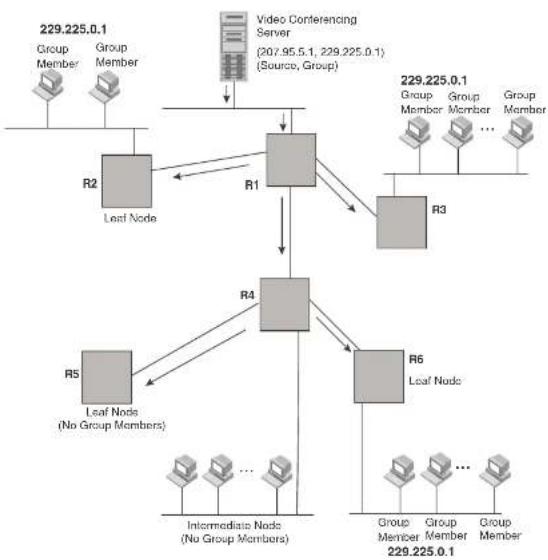
flowchart
graph TD
A["Video Conferencing Server (207.95.5.1, 229.225.0.1) (Source, Group)"] --> B["R1"]
B --> C["R2"]
B --> D["R3"]
C --> E["R4"]
D --> E
E --> F["R5"]
E --> G["R6"]
F --> H["Intermediate Node (No Group Members)"]
G --> I["Group Member 229.225.0.1"]
style A fill:#f9f,stroke:#333
style B fill:#ccc,stroke:#333
style C fill:#ccc,stroke:#333
style D fill:#ccc,stroke:#333
style E fill:#ccc,stroke:#333
style F fill:#ccc,stroke:#333
style G fill:#ccc,stroke:#333
style H fill:#ccc,stroke:#333
style I fill:#ccc,stroke:#333
FIGURE 121 Pruning leaf nodes from a multicast tree

flowchart
graph TD
A["Video Conferencing Server (207.65.1.1, 229.325.0.1) (Source, Group)"] --> B["R1"]
B --> C["R2"]
B --> D["R3"]
C --> E["R4"]
D --> E
E --> F["R5"]
E --> G["R6"]
F --> H["Lost Nodes (No Group Members)"]
G --> I["Intermediate Node (No Group Members)"]
H --> J["Group Member 229.225.0.1"]
I --> K["Group Member 229.225.0.1"]
style A fill:#f9f,stroke:#333
style B fill:#ccc,stroke:#333
style C fill:#ccc,stroke:#333
style D fill:#ccc,stroke:#333
style E fill:#ccc,stroke:#333
style F fill:#ccc,stroke:#333
style G fill:#ccc,stroke:#333
style H fill:#ccc,stroke:#333
style I fill:#ccc,stroke:#333
style J fill:#ccc,stroke:#333
style K fill:#ccc,stroke:#333
Grafts to a multicast Tree
A PIM switch restores pruned branches to a multicast tree by sending graft messages towards the upstream switch. Graft messages start at the leaf node and travel up the tree, first sending the message to its neighbor upstream switch.
- PIM DM V2 - sends messages to the multicast address 224.0.0.13 (ALL-PIM-ROUTERS) with protocol number 103
The CLI commands for configuring and managing PIM DM are the same for V1 and V2. The only difference is the command you use to enable the protocol on an interface.
NOTE
Version 2 is the default PIM DM version. The only difference between version 1 and version 2 is the way the protocol sends messages. The change is not apparent in most configurations. You can use version 2 instead of version 1 with no impact to your network. However, if you want to continue to use PIM DM V1 on an interface, you must change the version, then save the configuration.
NOTE
The note above does not mean you can run different PIM versions on devices that are connected to each other. The devices must run the same version of PIM. If you want to connect a Layer 3 Switch running PIM to a device that is running PIM V1, you must change the version on the Layer 3 Switch to V1 (or change the version on the device to V2, if supported).
Configuring PIM DM
NOTE
This section describes how to configure the “dense” mode of PIM, described in RFC 1075. Refer to “Configuring PIM Sparse” on page 744 for information about configuring PIM Sparse.
Enabling PIM on the router and an interface
By default, PIM is disabled. To enable PIM, perform the following:
- Enable the feature globally.
- Configure the IP interfaces that will use PIM.
- Enable PIM locally on the ports that have the IP interfaces you configured for PIM.
Suppose you want to initiate the use of desktop video for fellow users on a sprawling campus network. All destination marketing have the appropriate hardware and software but the Dell
- Entering a no router pim command removes all configuration for PIM multicast on a Layer 3 Switch (router pim level) only.
Globally Enabling and Disabling PIM without Deleting Multicast Configuration
As stated above entering a no router pim command deletes the PIM configuration. If you want to disable PIM without deleting any PIM configuration, enter the following command.
PowerConnect {config}#router pim
PowerConnect {config-pim-router} #disable-pim
Syntax: [no] disable-pim
Use the [no] version of the command to re-enable PIM.
Enabling a PIM version
Using the CLI
To enable PIM on an interface, globally enable PIM, then enable PIM on interface 3, enter the following commands.
PowerConnect(config)#router pin
PowerConnect(config)#int e 3
PowerConnect(config-if-e1000-3)#ip add
PowerConnect(config=IF=61000-3)#ip pim
Syntax: [no] ip pim [version 1 | 2]
The version 1 | 2 parameter specifies the PIM DM version. The default version is 2.
If you have enabled PIM version 1 but need to enable version 2 instead, enter either of the following commands at the configuration level for the interface.
PowerConnect{config-if-1/1}#ip pim version 2
PowerConnect(config-if-1/1)#no ip pim version 1
To disable PIM DM on the interface, enter the following command.
PowerConnect(config-if-1/1)#no ip pim
Modifying DIM global parameters
To apply a PIM neighbor timeout value of 360 seconds to all ports on the router operating with PIM, enter the following.
PowerConnect(config)#router pin
PowerConnect(config-pim-router)#nbr-timeout 360
Syntax: nbr-timeout <60-8000>
The default is 180 seconds.
Modifying hello timer
This parameter defines the interval at which periodic hellos are sent out PIM interfaces. Routers use hello messages to inform neighboring routers of their presence. The default rate is 60 seconds.
To apply a PIM hello timer of 120 seconds to all ports on the router operating with PIM, enter the following.
PowerConnect{config}#router pim
PowerConnect(config-pim-router)#hello-timer 120
Syntax: hello-timer <10-3600>
The default is 60 seconds.
Modifying prune timer
This parameter defines how long a PIM router will maintain a prune state for a forwarding entry.
The first received multicast interface is forwarded to all other PIM interfaces on the router. If there is no presence of groups on that interface, the leaf node sends a prune message upstream and stores a prune state. This prune state travels up the tree and installs a prune state.
A prune state is maintained until the prune timer expires or a graft message is received for the forwarding entry. The default value is 180 seconds.
To set the PIM prune timer to 90, enter the following.
PowerConnect(config)#router pin
PowerConnect(config-pim-router)#prune-timer 90
Contour range times <10 2600s
where
Viewing the prune wait time
To view the prune wait time, enter the show ip pim dense command at any level of the CLI.
PowerConnect+show ip pim dense
Global FIM Dense Mode Settings
Hello interval: 60, Neighbor timeout: 180
Graft Retransmit interval: 10, Inactivity interval: 180
Route Expire interval: 200, Route Discard interval: 340
Prune age: 180, Prune wait: 3
Modifying graft retransmit timer
The Graft Retransmit Timer defines the interval between the transmission of graft messages.
A graft message is sent by a router to cancel a prune state. When a router receives a graft message, the router responds with a Graft Ack (acknowledge) message. If this Graft Ack message is lost, the router that sent the graft message will resend it.
To change the graft retransmit timer from the default of 180 to 90 seconds, enter the following.
PowerConnect(config)#router pin
PowerConnect(config-pim-router)#graft-retransmit-timer 10
Syntax: graft-retransmit-timer <2 -10>
The default is 3 seconds.
Modifying inactivity timer
The router deletes a forwarding entry if the entry is not used to send multicast packets. The PIM inactivity timer defines how long a forwarding entry can remain unused before the router deletes it.
To apply a PIM inactivity timer of 90 seconds to all PIM interfaces, enter the following.
PowerConnect(config)#router pim
PowerConnect(config pin router)#inactivity timer 90
Total number of IP routes: 19
| S:BGP D:Connected R:HIP S:Static O:OSPF *:Candidate default | |||||
| Destination | NetMask | Gateway | Port | Cost Type | |
| 9 | 172.17.41.4 | 255.255.255.252*137.80.127.3 | v11 | 2 | O |
| 172.17.41.4 | 255.255.255.252 137.80.126.3 | v10 | 2 | O | |
| 172.17.41.4 | 255.255.255.252 137.80.129.1 | v13 | 2 | O | |
| 172.17.41.4 | 255.255.255.252 137.80.128.3 | v12 | 2 | O | |
| 10 | 172.17.41.8 | 255.255.255.252 0.0.0.0 | 1/2 | 1 | D |
When the Highest IP RPF feature is enabled, the selection of the shortest path back to the source is based on which Reverse Path Forwarding (RPF) neighbor in the IP routing table has the highest IP address, if the cost of the routes are the same. For example, in the table above, Gateway 137.80.129.1 will be chosen as the shortest path to the source because it is the RPF neighbor with the highest IP address.
When choosing the RPF, the router first checks the Multicast Routing Table. If the table is not available, it chooses an RPF from the IP Routing Table. Multicast route is configured using the ip mroute command.
To enable the Highest IP RPF feature, enter commands such as the following.
PowerConnect{config}#router pim
PowerConnect (config-pim-router) #highest-ip-rpf
The command immediately enables the Highest IP RPF feature; there is no need to reboot the device.
Syntax: [no] highest-ip-rpf
Entering the no version of the command disables the feature; the shortest path back to the source will be based on the first entry in the IP routing table. If some PIM traffic paths were selected based on the highest IP RPF, these paths are changed immediately to use the first RPF in the routing table.
Failover time in a multi-path topology
Configuration notes
- If the TTL for an interface is greater than 1, PIM packets received on the interface are always forwarded in software because each packet TTL must be examined. Therefore, Dell does not recommend modifying the TTL under normal operating conditions.
- Multicast packets with a TTL value of 1 are switched within the same VLAN. These packets cannot be routed between different VLANs.
Configuration syntax
To configure a TTL of 24, enter the following.
PowerConnect(config-if-3/24)*ip pim ttl 24
Syntax: ip pim ttl <1-31>
Dropping PIM traffic in hardware
Unwanted PIM Dense or PIM Sparse multicast traffic can be dropped in hardware on Layer 3 Switches. This feature does not apply to DVMRP traffic. Refer to "Passive multicast route insertion" on page 763.
PIM Sparse
Dell PowerConnect devices support Protocol Independent Multicast (PIM) Sparse version 2. PIM Sparse provides multicasting that is especially suitable for widely distributed multicast environments. The Dell implementation is based on RFC 2362.
In a PIM Sparse network, a PIM Sparse router that is connected to a host that wants to receive information for a multicast group must explicitly send a join request on behalf of the receiver (host).
PIM Sparse routers are organized into domains. A PIM Sparse domain is a contiguous set of routers that all implement PIM and are configured to operate within a common boundary. Figure 122 shows a simple example of a PIM Sparse domain. This example shows three Layer 3 Switches
FIGURE 122 Example of a PIM Sparse domain

flowchart
graph TD
A["RM Space Node A"] -->|207.85.1| B["Node A"]
A -->|207.85.1| C["Node B"]
B -->|209.157.24.15| D["Source for Group 239.299.162.1"]
C -->|207.85.1| E["Shortest Path Time (SPT) path"]
E -->|207.85.1| F["Node B"]
F -->|207.85.1| G["Node B"]
G -->|207.85.1| H["Node B"]
H -->|207.85.1| I["Node B"]
I -->|207.85.1| J["Node B"]
J -->|207.85.1| K["Node B"]
K -->|207.85.1| L["Node B"]
L -->|207.85.1| M["Node B"]
M -->|207.85.1| N["Node B"]
N -->|207.85.1| O["Node B"]
O -->|207.85.1| P["Node B"]
P -->|207.85.1| Q["Node B"]
Q -->|207.85.1| R["Node B"]
R -->|207.85.1| S["Node B"]
S -->|207.85.1| T["Node B"]
T -->|207.85.1| U["Node B"]
U -->|207.85.1| V["Node B"]
V -->|207.85.1| W["Node B"]
W -->|207.85.1| X["Node B"]
X -->|207.85.1| Y["Node B"]
Y -->|207.85.1| Z["Node B"]
Z -->|207.85.1| AA["Node B"]
AA -->|207.85.1| AB["Node B"]
AB -->|207.85.1| AC["Node B"]
AC -->|207.85.1| AD["Node B"]
AD -->|207.85.1| AE["Node B"]
AE -->|207.85.1| AF["Node B"]
AF -->|207.85.1| AG["Node B"]
AG -->|207.85.1| AH["Node B"]
AH -->|207.85.1| AI["Node B"]
AI -->|207.85.1| AJ["Node B"]
AJ -->|207.85.1| AK["Node B"]
AK -->|207.85.1| AL["Node B"]
AL -->|207.85.1| AM["Node B"]
AM -->|207.85.1| AN["Node B"]
AN -->|207.85.1| AO["Node B"]
AO -->|207.85.1| AP["Node B"]
AP -->|207.85.1| AQ["Node B"]
AQ -->|207.85.1| AR["Node B"]
AR -->|207.85.1| AS["Node B"]
AS -->|207.85.1| AT["Node B"]
AT -->|207.85.1| AU["Node B"]
AU -->|207.85.1| AV["Node B"]
AV -->|207.85.1| AW["Node B"]
AW -->|207.85.1| AX["Node B"]
AX -->|207.85.1| AY["Node B"]
AY -->|207.85.1| AZ["Node B"]
AZ -->|207.85.1| BA["Node B"]
BA -->|207.85.1| BB["Node B"]
BB -->|207.85.1| BC["Node B"]
BC -->|207.85.1| BD["Node B"]
BD -->|207.85.1| BE["Node B"]
BE -->|207.85.1| BF["Node B"]
BF -->|207.85.1| BG["Node B"]
BG -->|207.85.1| BH["Node B"]
BH -->|207.85.1| BI["Node B"]
BI -->|207.85.1| BJ["Node B"]
BJ -->|207.85.1| BK["Node B"]
BK -->|207.85.1| BL["Node B"]
BL -->|207.85.1| BM["Node B"]
BM -->|207.85.1| BN["Node B"]
BN -->|207.85.1| BO["Node B"]
BO -->|207.85.1| BP["Node B"]
BP -->|207.85.1| BQ["Node B"]
PIM Sparse switch types
Switches that are configured with PIM Sparse interfaces also can be configured to fill one or more of the following roles:
- PMBR – A PIM switch that has some interfaces within the PIM domain and other interface outside the PIM domain. PBMRs connect the PIM domain to the Internet.
NOTE
You cannot configure a Dell routing interface as a PMBR interface for PIM Sparse in the current software release.
To enhance overall network performance, Layer 3 Switches use the RP to forward only the first packet from a group source to the group receivers. After the first packet, the Layer 3 Switch calculates the shortest path between the receiver and source (the Shortest Path Tree, or SPT) and uses the SPT for subsequent packets from the source to the receiver. The Layer 3 Switch calculates a separate SPT for each source-receiver pair.
NOTE
Dell recommends that you configure the same ports as candidate BSRs and RPs.
RP paths and SPT paths
Figure 122 shows two paths for packets from the source for group 239.255.162.1 and a receiver for the group. The source is attached to PIM Sparse Switch A and the recipient is attached to PIM Sparse Switch C. PIM Sparse Switch B in is the RP for this multicast group. As a result, the default path for packets from the source to the receiver is through the RP. However, the path through the RP sometimes is not the shortest path. In this case, the shortest path between the source and the receiver is over the direct link between Switch A and Switch C, which bypasses the RP (Switch B).
To optimize PIM traffic, the protocol contains a mechanism for calculating the Shortest Path Tree (SPT) between a given source and receiver. PIM Sparse switches can use the SPT as an alternative to using the RP for forwarding traffic from a source to a receiver. By default, Layer 3 Switches forward the first packet they receive from a given source to a given receiver using the RP path, but forward subsequent packets from that source to that receiver through the SPT. In Figure 122, Switch A forwards the first packet from group 239.255.162.1 source to the destination by sending the packet to Switch B, which is the RP. Switch B then sends the packet to Switch C. For the second and all future packets that Switch A receives from the source for the receiver, Switch A forwards them directly to Switch C using the SPT path.
Configuring PIM Sparse
To configure a Layer 3 Switch for PIM Sparse, perform the following tasks:
- Configure the following global parameter:
- Enable the DIM Caps mode of multiagent routing
NOTE
Dell recommends that you configure the same Layer 3 Switch as both the BSR and the RP.
Limitations
The implementation of PIM Sparse in the current software release has the following limitations:
- PIM Border Routers (PMBRs) are not supported. Thus, you cannot configure a Dell routing interface as a PMBR interface for PIM Sparse.
- PIM Sparse and regular PIM (dense mode) cannot be used on the same interface.
- You cannot configure or display PIM Sparse information using the Web Management Interface. (You can display some general PIM information, but not specific PIM Sparse information.)
Configuring Global PIM Sparse parameters
To configure the PIM Sparse global parameters, use either of the following methods.
To configure basic global PIM Sparse parameters, enter commands such as the following on each Layer 3 Switch within the PIM Sparse domain.
PowerConnect(config)#router pim
Syntax: [no] router pim
NOTE
You do not need to globally enable IP multicast routing when configuring PIM Sparse.
The command in this example enables IP multicast routing, and enables the PIM Sparse mode of IP multicast routing. The command does not configure the Layer 3 Switch as a candidate PIM Sparse Bootstrap Router (BSR) and candidate Rendezvous Point (RP). You can configure a Layer 3 Switch as a PIM Sparse switch without configuring the it as a candidate BSR and RP. However, if you do configure the Layer 3 Switch as one of these, Dell recommends that you configure it as both. Refer to "Configuring BSRs" on page 746.
The behavior of the [no] router pim command is as follows:
Configuring PIM interface parameters
After you enable IP multicast routing and PIM Sparse at the global level, you must enable it on the individual interfaces connected to the PIM Sparse network. To do so, use the following CLI method.
To enable PIM Sparse mode on an interface, enter commands such as the following.
PowerConnect(config)#interface ethernet 2/2
PowerConnect(config-if-2/2)#ip address 207.95.7.1 255.255.255.0
PowerConnect (config-1f-2/2) #1p pim-sparse
Syntax: [no] ip pim-sparse
The commands in this example add an IP interface to port 2/2, then enable PIM Sparse on the interface.
If the interface is on the border of the PIM Sparse domain, you also must enter the following command.
PowerConnect(config-if-2/2)#ip pim border
Syntax: [no] ip pim border
NOTE
You cannot configure a Dell routing interface as a PMBR interface for PIM Sparse in the current software release.
Configuring BSRs
In addition to the global and interface parameters in the sections above, you need to identify an interface on at least one Layer 3 Switch as a candidate PIM Sparse Bootstrap router (BSR) and candidate PIM Sparse Rendezvous Point (RP).
NOTE
It is possible to configure the Layer 3 Switch as only a candidate BSR or RP, but Dell recommends that you configure the same interface on the same Layer 3 Switch as both a BSR and an RP.
This section presents how to configure BSRs. Refer to "Configuring RPs" on page 747 for
- Enter ve
for a virtual interface. - Enter loopback
for a loopback interface.
Theparameter specifies the number of bits in a group address that are significant when calculating the group-to-RP mapping. You can specify a value from 1 - 32.
NOTE
Dell recommends you specify 30 for IP version 4 (IPv4) networks.
The
Configuring RPs
Enter a command such as the following to configure the Layer 3 Switch as a candidate RP. PowerConnect(config-pim-router)#rp-candidate ethernet 2/2
Syntax: [no] rp-candidate ethernet [
The
- Enter ethernet [
/] for a physical interface (port). - Enter ve
for a virtual interface. - Enter loopback
for a loopback interface.
By default, this command configures the Layer 3 Switch as a candidate RP for all group numbers beginning with 224. As a result, the Layer 3 Switch is a candidate RP for all valid PIM Sparse group numbers. You can change this by adding or deleting specific address ranges. The following example narrows the group number range for which the Layer 3 Switch is a candidate RP by explicitly adding a range.
PowerConnect{config-pim-router}#rp-candidate add 224.126.0.0 16
Updating PIM-Sparse forwarding entries with new RP configuration
If you make changes to your static RP configuration, the entries in the PIM-Sparse multicast forwarding table continue to use the old RP configuration until they are aged out.
The clear pim rp-map command allows you to update the entries in the static multicast forwarding table immediately after making RP configuration changes. This command is meant to be used with rp-address command.
To update the entries in a PIM sparse static multicast forwarding table with new RP configuration, enter the following command at the privileged EXEC level of the CLI.
PowerConnect#clear pim rp-map
Syntax: clear pim rp-map
Statically specifying the RP
Dell recommends that you use the PIM Sparse protocol RP election process so that a backup RP can automatically take over if the active RP router becomes unavailable. However, if you do not want the RP to be selected by the RP election process but instead you want to explicitly identify the RP by its IP address, you can do using the following CLI method.
If you explicitly specify the RP, the Layer 3 Switch uses the specified RP for all group-to-RP mappings and overrides the set of candidate RPs supplied by the BSR.
NOTE
Specify the same IP address as the RP on all PIM Sparse routers within the PIM Sparse domain. Make sure the router is on the backbone or is otherwise well connected to the rest of the network.
To specify the IP address of the RP, enter commands such as the following.
PowerConnect(config)#router pim
PowerConnect{config-pim-router}#rp-address 207.95.7.1
Syntax: [no] rp-address
The
The command in the example above identifies the router interface at IP address 207.95.7.1 as the RP for the PIM Sparse domain. The Layer 3 Switch will use the specified RP and ignore group-to-RP
By default, the device switches from the RP to the SPT after receiving the first packet for a given PIM Sparse group. The Layer 3 Switch maintains a separate counter for each PIM Sparse source-group pair.
After the Layer 3 Switch receives a packet for a given source-group pair, the Layer 3 Switch starts a PIM data timer for that source-group pair. If the Layer 3 Switch does not receive another packet for the source-group pair before the timer expires, it reverts to using the RP for the next packet received for the source-group pair. In accordance with the PIM Sparse RFC recommendation, the timer is 210 seconds and is not configurable. The counter is reset to zero each time the Layer 3 Switch receives a packet for the source-group pair.
You can change the number of packets that the Layer 3 Switch sends using the RP before switching to using the SPT. To do so, use the following CLI method.
PowerConnect {config} #router pim
PowerConnect(config-pim-router)#spt-threshold 1000
Syntax: [no] spt-threshold infinity |
The infinity |
Changing the PIM join and prune message interval
By default, the Layer 3 Switch sends PIM Sparse Join/Prune messages every 60 seconds. These messages inform other PIM Sparse routers about clients who want to become receivers (Join) or stop being receivers (Prune) for PIM Sparse groups.
You can change the Join/Prune message interval using the following CLI method.
NOTE
Use the same Join/Prune message interval on all the PIM Sparse routers in the PIM Sparse domain. If the routers do not all use the same timer interval, the performance of PIM Sparse can be adversely affected.
Displaying PIM Sparse configuration information and statistics
You can display the following PIM Sparse information:
- Basic PIM Sparse configuration information
- Group information
- BSR information
• Candidate RP information
• RP-to-group mappings
• RP information for a PIM Sparse group - RP set list
• PIM Neighbor information - The PIM flow cache
• The PIM multicast cache - PIM traffic statistics
Displaying basic PIM Sparse configuration information
To display basic configuration information for PIM Sparse, enter the following command at any CLI level.
PowerConnect+show ip pim sparse
Global PTM Sparse Mode Settings
Hello interval: 60, Neighbor timeout: 180
Bootstrap Msg interval: 130, Candidate-RP Advertisement interval: 60
Join/Prune interval: 60, SPT Threshold: 1
Interface Ethernet e3/8
TTL Threshold: 1, Enabled
Local Address: 207.95.8.1
TABLE 127 Output of show ip pim sparse (Continued)
| This field... Displays... | |
| Neighbor timeout How many seconds the Layer 3 Switch will wait for a hello message from a neighbor before determining that the neighbor is no longer present and removing cached PIM Sparse forwarding entries for the neighbor. | |
| Bootstrap Msg interval | How frequently the BSR configured on the Layer 3 Switch sends the RP set to the RPs within the PIM Sparse domain. The RP set is a list of candidate RPs and their group prefixes. A candidate RP group prefix indicates the range of PIM Sparse group numbers for which it can be an RP.NOTE: This field contains a value only if an interface on the Layer 3 Switch is elected to be the BSR. Otherwise, the field is blank. |
| Candidate RP Advertisement Interval | How frequently the candidate PR configured on the Layer 3 Switch sends candidate RP advertisement messages to the BSR.NOTE: This field contains a value only if an interface on the Layer 3 Switch is configured as a candidate RP. Otherwise, the field is blank. |
| Join/Prune interval How frequently the Layer 3 Switch sends PIM Sparse Join/Prune messages for the multicast groups it is forwarding. This field shows the number of seconds between Join/Prune messages.The Layer 3 Switch sends Join/Prune messages on behalf of multicast receivers who want to join or leave a PIM Sparse group. When forwarding packets from PIM Sparse sources, the Layer 3 Switch sends the packets only on the interfaces on which it has received join requests in Join/Prune messages for the source group.You can change the Join/Prune interval if needed. Refer to “Changing the PIM join and prune message interval” on page 749. | |
| SPT Threshold The number of packets the Layer 3 Switch sends using the path through the RP before switching to using the SPT path. | |
PIM Sparse interface information
NOTE: You also can display IP multicast interface information using the show ip pim interface command. However, this command lists all IP multicast interfaces, including regular PIM (dense mode) and DVMRP interfaces. The show ip pim sparse command lists only the PIM Sparse interfaces.
Interface The type of interface and the interface number. The interface type can be one of the following: • Ethernet
PowerConnect#show ip pim group
Total number of Groups: 2
Index 1 Group 239.255.162.1 Ports e3/11
Syntax: show ip pim group
This display shows the following information.
TABLE 128 Output of show ip pim group
| This field... Displays... |
| Total number of Groups Lists the total number of IP multicast groups the Layer 3 Switch is forwarding. NOTE: This list can include groups that are not PIM Sparse groups. If interfaces on the Layer 3 Switch are configured for regular PIM (dense mode) or DVMRP, these groups are listed too. |
| Index The index number of the table entry in the display. |
| Group The multicast group address |
| Ports The Layer 3 Switch ports connected to the receivers of the groups. |
Displaying BSR information
To display BSR information, enter the following command at any CLI level.
PowerConnect#show ip pim bar
PIMv2 Bootstrap information
This system is the elected Bootstrap Router (BSR)
BSR address: 207.95.7.1
Uptime: 00:33:52, BSR priority: 5, Hash mask length: 32
Next bootstrap message in 00:00:20
Next Candidate-RP-advertisement in 00:00:10
RP: 207.95.7.1
proun preFixes:
TABLE 129 Output of show ip pim bsr
| This field... Displays... | |
| BSR address or local BSR address | The IP address of the interface configured as the PIM Sparse Bootstrap Router (BSR).NOTE: If the word "local" does not appear in the field, this Layer 3 Switch is the BSR. If the word "local" does appear, this Layer 3 Switch is not the BSR. |
| Uptime The amount of time the BSR has been running.NOTE: This field appears only if this Layer 3 Switch is the BSR. | |
| BSR priority or local BSR priority | The priority assigned to the interface for use during the BSR election process. During BSR election, the priorities of the candidate BSRs are compared and the interface with the highest BSR priority becomes the BSR.NOTE: If the word "local" does not appear in the field, this Layer 3 Switch is the BSR. If the word "local" does appear, this Layer 3 Switch is not the BSR. |
| Hash mask length The number of significant bits in the IP multicast group comparison mask. This mask determines the IP multicast group numbers for which the Layer 3 Switch can be a BSR.The default is 32 bits, which allows the Layer 3 Switch to be a BSR for any valid IP multicast group number.NOTE: This field appears only if this Layer 3 Switch is the BSR. | |
| Next bootstrap message In | Indicates how many seconds will pass before the BSR sends its next Bootstrap message.NOTE: This field appears only if this Layer 3 Switch is the BSR. |
| Next Candidate-PR-advertisomont message in | Indicates how many seconds will pass before the BSR sends its next candidate PR advertisement message.NOTE: This field appears only if this Layer 3 Switch is the BSR. |
| RP Indicates the IP address of the Rendezvous Point (RP).NOTE: This field appears only if this Layer 3 Switch is the BSR. | |
| group prefixes Indicates the multicast groups for which the RP listed by the previous field is a candidate RP.NOTE: This field appears only if this Layer 3 Switch is the BSR. | |
| Candidate RP-advertisomont period | Indicates how frequently the BSR sends candidate RP advertisement messages.NOTE: This field appears only if this Layer 3 Switch is the BSR. |
PowerConnect#show ip pim resource
| alloc | in-use | avail | allo-fail | up-limit | got-mcm | |
| NBR lixt | 64 | 0 | 64 | 0 | 512 | 0 |
| timer | 256 | 0 | 256 | 0 | 4096 | 0 |
| pimsm J/P elem | 0 | 0 | 0 | 0 | 43960 | 0 |
| pimsm group2rp | 0 | 0 | 0 | 0 | 4096 | 0 |
| pimsm L2 reg xmt | 64 | 0 | 64 | 0 | no-limit | 0 |
| mcache | 256 | 0 | 256 | 0 | 1024 | 0 |
| mcache hash link | 987 | 0 | 987 | 0 | no-limit | 0 |
| mcache Zna hash | 9 | 0 | 9 | 0 | 997 | 0 |
| graft if no mcache | 197 | 0 | 197 | 0 | no-limit | 0 |
| pim/dvm global group | 256 | 0 | 256 | 0 | no-limit | 0 |
| pim/dvmrp prune | 128 | 0 | 128 | 0 | 40960 | 0 |
| Output intf-vlan | 2000 | 0 | 2000 | 0 | no-limit | 0 |
| group hash link | 97 | 0 | 97 | 0 | no-limit | 0 |
| 2D vlan for nbr, glb | 2000 | 0 | 2000 | 0 | no-limit | 0 |
| Output intf. | 1024 | 0 | 1024 | 0 | no-limit | 0 |
| 2D for glb grp | 1024 | 0 | 1024 | 0 | no-limit | 0 |
| pim/dvm config, intf | 128 | 2 | 126 | 0 | no-limit | 2 |
| Prune rate limit | 256 | 0 | 256 | 0 | no-limit | 0 |
| Distributed add cpu | 128 | 0 | 128 | 0 | no-limit | 0 |
| L2 VIDX | 256 | 0 | 256 | 0 | 4096 | 0 |
| L2 VIDX hash | 997 | 0 | 997 | 0 | no-limit | 0 |
| igmp group | 256 | 0 | 256 | 0 | 4096 | 0 |
| igmp phy port | 1024 | 0 | 1024 | 0 | no-limit | 0 |
| igmp exist phy port | 1024 | 4 | 1020 | 0 | no-limit | 4 |
| igmp G/GS query | 128 | 0 | 128 | 0 | no-limit | 0 |
| igmp v3 source | 2000 | 0 | 2000 | 0 | 500000 | 0 |
| igmp v3 tracking | 0 | 0 | 0 | 0 | no-limit | 0 |
| igmp glb sorted list | 2000 | 0 | 2000 | 0 | 500000 | 0 |
| total pool memory 266%18 bytes | ||||||
of PIM ports: physical 2, VEs 0 (max: 512), loopback 0, tunnels 0
Total Mlls in pool: 943 Allocated MLL: 0 Available MLL: 943
SW processed pkls 0
Syntax: show ip pim resource
For each software data structure listed in the output, the following information is shown.
NOTE
When the product of the number of active PIM interfaces multiplied by the number of multicast streams exceeds the total number of MLL, the CLI displays the message, "MLL pool out of memory".
NOTE
The total number of MLL available changes according to the hardware configuration.
Displaying candidate RP information
To display candidate RP information, enter the following command at any CLI level.
PowerConnect#show ip pim rp-candidate
Next Candidate-RP-advertisement in 00:00:10
RP: 207.95.7.1
group prefixes:
224.0.0.0 / 4
Candidate-RP-advertisement period: 60
This example shows information displayed on a Layer 3 Switch that is a candidate RP. The following example shows the message displayed on a Layer 3 Switch that is not a candidate RP.
PowerConnect#show ip pim rp-candidate
This system is not a Candidate-RP.
Syntax: show ip pim rp-candidate
This display shows the following information.
TABLE 131 Output of show ip pim rp-candidate
This field... Displays...
| Candidate RP advertisement in | Indicates how many seconds will pass before the BSR sends its next RP message. |
| NOTE: This field appears only if this layer 3. Switch is a candidate RP |
| 1 | 239.255.163.1 | 99.99.99.5 |
| 2 | 239.255.163.2 | 99.99.99.5 |
| 3 | 239.255.163.3 | 99.99.99.5 |
| 4 | 239.255.162.1 | 99.99.99.5 |
| 5 | 239.255.162.2 | 43.43.43.1 |
| 6 | 239.255.162.3 | 99.99.99.5 |
Syntax: show ip pim rp-map
This display shows the following information.
TABLE 132 Output of show ip pim rp-map
| This field... Displays... |
| Group address Indicates the PIM Sparse multicast group address using the listed RP. |
| RP address Indicates the IP address of the Rendezvous Point (RP) for the listed PIM Sparse group. |
Displaying RP information for a PIM Sparse group
To display RP information for a PIM Sparse group, enter the following command at any CLI level.
PowerConnect#show ip pim rp-hash 239.255.162.1
RF: 207.95.7.1, v2
Info source: 207.95.7.1, through bootstrap
Syntax: show ip pim rp-hash
The
This display shows the following information.
TABLE 133 Output of show ip pim rp-hash
| This field... Displays... |
| RP Indicates the IP address of the Rendezvous Point (RP) for the specified PIM Sparse group.Following the IP address is the port or virtual interface through which this Layer 3 Switch learned the identity of the RP. |
This display shows the following information.
TABLE 134 Output of show ip pim rp-set
| This field... Displays... | |
| Number of group prefixes The number f PIM Sparse group prefixes for which the RP is responsible. | |
| Group prefix Indicates the multicast groups for which the RP listed by the previous field is a candidate RP. | |
| RPs expected/received Indicates how many RPs were expected and received in the latest Bootstrap message. | |
| RPIndicates the RP number. If there are multiple RPs in the PIM Sparse domain, a line of information for each of them is listed, and they are numbered in ascending numerical order. | |
| priority The RP priority of the candidate RP. During the election process, the candidate RP with the highest priority is elected as the RP. | |
| ago The age (in seconds) of this RP-sct.NOTE: If this Layer 3 Switch is not a BSR, this field contains zero. Only the BSR ages the RP-set. |
Displaying multicast neighbor information
To display information about the Layer 3 Switch PIM neighbors, enter the following command at any CLI level.
PowerConnect+show ip pim nbr
| Port | Neighbor | Holdtime | Age | UpTime |
| soc | soc | soc | ||
| e3/8 | 207.95.8.10 | 180 | 60 | 900 |
| Port | Neighbor | Holdtime | Age | UpTime |
| soc | soc | soc | ||
| v1 | 207.95.6.2 | 180 | 60 | 900 |
Syntax: show ip pim nbr
TABLE 135 Output of show ip pim nbr (Continued)
| This field... Displays... |
| Age sec The number of seconds since the Layer 3 Switch received the last hello message from the neighbor. |
| UpTime sec The number of seconds the PIM neighbor has been up. This timer starts when the Layer 3 Switch receives the first Hello messages from the neighbor. |
Displaying information about an upstream neighbor device
You can view information about the upstream neighbor device for a given source IP address for IP Protocol Independent Multicast (PIM). For PIM, the software uses the IP route table or multicast route table to lookup the upstream neighbor device.
Enter the following command at the Privileged EXEC level of the CLI.
PowerConnect#show ip pim rpf 1.1.20.2
directly connected or through an L2 neighbor
Syntax: show ip pim | dvmrp rpf
where
NOTE
If there are multiple equal cost paths to the source, the show ip pim rpf command output may not be accurate. If your system has multiple equal cost paths, use the command show ip pim mcache to view information about the upstream neighbor.
Displaying the PIM flow cache
To display the PIM flow cache, enter the following command at any CLI level.
PowerConnect#show ip pim flowcache
| Source | Group | Parent | CamFlags | CamIndex | Fid | Flags | |
| 1 | 209.157.24.162 | 239.255.162.1 | v2 | 00000700 | 2023 | 00004411 | F |
TABLE 136 Output of show ip pim flowcache (Continued)
| This field... | Displays... |
| Fid This field is used for troubleshooting. | |
| Flags This field is used for troubleshooting. | |
Displaying the PIM multicast cache
To display the PIM multicast cache, enter the following command at any CLI level.
PowerConnect#show ip pim meache
1 (x,239.255.162.1) RP207.95.7.1 forward port v1, Count 2
member ports ethe 3/3
virtual ports v2
prune ports
virtual prune ports
2 (209.157.24.162,239.255.162.4) forward port v2, flags 00006900 Count 130
member ports
virtual ports
prune ports
virtual prune ports
3 (209.157.24.162,239.255.162.1) forward port v2, flags 00005a01 Count 12
member ports ethe 3/8
virtual ports
prune ports
virtual prune ports
Syntax: show ip pim mcache
This display shows the following information.
TABLE 137 Output of show ip pim mcache
This field... Displays...
TABLE 137 Output of show ip pim mcache (Continued)
| This field... Displays... |
| RPT Indicates whether the cache entry uses the RP path or the SPT path. The RPT flag can have one of the following values:0 - The SPT path is used instead of the RP path.1 - The RP path is used instead of the SPT path.NOTE: The values of the RP and SPT flags are always opposite (one is set to 0 and the other is set to 1). |
| SPT Indicates whether the cache entry uses the RP path or the SPT path. The SP flag can have one of the following values:0 - The RP path is used instead of the SPT path.1 - The SPT path is used instead of the RP path.NOTE: The values of the RP and SPT flags are always opposite (one is set to 0 and the other is set to 1). |
| Register Suppress Indicates whether the Register Suppress timer is running. This field can have one of the following values:0 - The timer is not running.1 - The timer is running. |
| member ports Indicates the Layer 3 Switch physical ports to which the receivers for the source and group are attached. The receivers can be directly attached or indirectly attached through other PIM Sparse routers. |
| virtual ports indicates the virtual Interfaces to which the receivers for the source and group are attached. The receivers can be directly attached or indirectly attached through other PIM Sparse routers. |
| prune ports Indicates the physical ports on which the Layer 3 Switch has received a prune notification (in a Join/Prune message) to remove the receiver from the list of recipients for the group. |
| virtual prune ports Indicates the virtual interfaces ports on which the Layer 3 Switch has received a prune notification (in a Join/Prune message) to remove the receiver from the list of recipients for the group. |
Displaying PIM traffic statistics
To display PIM traffic statistics, use the following CLI method.
PowerConnect+show ip pim traffic
| Port | Hello | J/P | Register | RegStop | Assert | |||||
| [Rx | Tx] | [Rx | Tx] | [Rx | Tx] | [Rx | Tx] | [Rx | Tx] | |
| e3/8 | 19 | 19 | 32 | 0 | 0 | 0 | 37 | 0 | 0 | 0 |
| Port | Hello | J/P | Registor | RegStop | Assert | |||||
| [Rx | Tx] | [Rx | Tx] | [Rx | Tx] | [Rx | Tx] | [Rx | Tx] | |
| v1 | 18 | 19 | 0 | 20 | 0 | 0 | 0 | 0 | 0 | 0 |
| Port | Hello | J/P | Register | RegStop | Assert | |||||
| [Rx | Tx] | [Rx | Tx] | [Rx | Tx] | [Rx | Tx] | [Rx | Tx] | |
| v2 | 0 | 19 | 0 | 0 | 0 | 16 | 0 | 0 | 0 | 0 |
| Total | 37 | 57 | 32 | 0 | 0 | 0 | 0 | 0 | 0 | 0 |
IGFP Statistics:
Total Recv/Xmit 85/110
Total Discard/chksum 0/0
Syntax: show ip pim traffic
NOTE
If you have configured interfaces for standard PIM (dense mode) on the Layer 3 Switch, statistics for these interfaces are listed first by the display.
This display shows the following information.
TABLE 138 Output of show ip pim traffic
This field... Displays...
Port The port or virtual Interface on which the PIM Interface is configured.
Hello The number of PIM Hello messages sent or received on the interface.
I/P The number of Inin/Prune messages sent or received on the interface
Syntax: show ip pim error
This command displays the number of warnings and non-zero PIM errors on the device. This count can increase during transition periods such as reboots and topology changes; however, if the device is stable, the number of errors should not increase. If warnings keep increasing in a stable topology, then there may be a configuration error or problems on the device.
To clear the counter for PIM errors, enter the following command.
PowerConnect#clear pin counters
Syntax: clear pim counters
PIM Passive
PIM Passive is used to reduce and minimize unnecessary PIM Hello and other PIM control messages.
PIM Passive allows you to specify that the interface is "passive" in regards to PIM. No PIM control packets are sent or processed (if received), but hosts can still send and receive multicast traffic and IGMP control traffic on that interface. Also, PIM Passive prevents any malicious router from taking over as the designated router (DR), which can prevent all hosts on the LAN from joining multicast traffic outside the LAN.
The following guidelines apply to PIM Passive:
- This is a Layer 3 interface [Ethernet/Ve] level feature.
- Since the loopback interfaces are never used to form PIM neighbors, this feature is not supported on loopback interface.
- Both PIM SM and PIM DM modes support this feature.
- Applying the PIM Passive on an interface requires PIM to be enabled on that interface.
- The sent and received statistics of a PIM Hello message are not changed for an interface, while it is configured as PIM passive.
To enable PIM Passive on an interface, enter the following command:
Passive multicast route insertion
Passive Multicast Route Insertion (PMRI) enables a Layer 3 switch running PIM Sparse to create an entry for a multicast route (e.g., (S,G)), with no directly attached clients or when connected to another PIM router (transit network).
PMRI is critical for Service Providers wanting to deliver IP-TV services or multicast-based video services. Service Providers, who have transit networks, distribute multicast-based video services to other Service Providers, regardless of whether a client subscribes to a video service.
PMRI is enabled by default. To disable it, enter the following command at the router pim level of the CLI.
PowerConnect(config)#router pim PowerConnect#(config-pim-router)#no hardware-drop
Syntax: [no] hardware-drop
When PMRI is enabled, the show ip pim mcache command output displays the multicast cache entry along with a drop flag, indicating that the device is dropping packets in hardware. If the HW flag is set to 1 (HW=1), it implies that the packets are being dropped in hardware. If the HW flag is set to 0, (HW=0), it indicates that the packets are being processed in software. The following shows an example display output.
PowerConnectfshow ip pim mcache
1 (10.10.10.18 226.0.1.56) in v10 {e1}, anti=2
Source is directly connected
Sparse Mode, RPT=0 SPT=1 REG=1 MGDP Adv=0 MGDP Create=0
fast=0 slow=0 pru=1 graft age drop
age=0s up-time=2m HW=1 L2-vldx=8191
Configuring an IP tunnel
IP tunnels are used to send traffic through routers that do not support IP multicasting. IP Multicast
PowerConnect(config)int el
PowerConnect(config-if-1)#ip tunnel 192.3.45.6
NOTE
The IP tunnel address represents the configured IP tunnel address of the destination router. In the case of Router A, its destination router is Router B. Router A is the destination router of Router B.
For router B, enter the following.
PowerConnect (config-if-1) #is tunnel 192.58.4.1
FIGURE 123 IP in IP tunneling on multicast packets in a unicast network
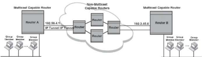
flowchart
graph LR
A["Router A\nGroup Member\nGroup Member\n..."] -->|192.58.4.1\nIP Tunnel IP Tunnel| B["Router"]
B --> C["Router"]
B --> D["Router"]
C --> E["Router"]
D --> F["Router"]
E --> G["Router B\nGroup Member\nGroup Member\n..."]
F --> H["Router B\nGroup Member\n..."]
style A fill:#f9f,stroke:#333
style B fill:#ccf,stroke:#333
style C fill:#cfc,stroke:#333
style D fill:#cfc,stroke:#333
style E fill:#fcc,stroke:#333
style F fill:#fcc,stroke:#333
style G fill:#cff,stroke:#333
style H fill:#ffc,stroke:#333
Using ACLs to control multicast features
You can use ACLs to control the following multicast features:
- Limit the number of multicast groups that are covered by a static rendezvous point (RP)
- Control which multicast groups for which candidate RPs sends advertisement messages to bootstrap routers
• Identify which multicast group packets will be forwarded or blocked on an interface
PowerConnect(config)#router pim
PowerConnect(config-pim-router)#ber-candidate ve 43 32 100
PowerConnect(config-pim-router)#rp-candidate ve 43 PowerConnect(config-pim-router)#rp-address 99.99.99.5 5
To configure an RP for multicast groups using the override switch, enter commands such as the following.
PowerConnect(config)#access-list 44 permit 239.255.162.0 0.0.0.255
PowerConnect(config)#router pim
PowerConnect(config-pim-router)#rp-address 43.43.43.1
PowerConnect(config-pim-router)#rp-address 99.99.99.5 44 override
Syntax: [no] rp-address
The access-list-num parameter is the number of the standard ACL that will filter the multicast group.
NOTE
Extended ACLs cannot be used to limit static RP groups.
The override parameter directs the Layer 3 Switch to ignore the information learned by a BSR if there is a conflict between the RP configured in this command and the information that is learned by the BSR. In previous releases, static RP configuration precedes the RP address learned from the PIM Bootstrap protocol. With this enhancement, an RP address learned dynamically from PIM Bootstrap protocol takes precedence over static RP configuration unless the override parameter is used.
You can use the show ip pim rp-set command to display the ACLs used to filter the static RP groups.
Example
PowerConnect#show ip pim rp-set
Group address Static-RP-address Override
Access-List 44 59.59.55.5 Cn
Number of group prefixes Learnt from BSR: 1
Group prefix = 224.0.0.0/4 #RPs: 1
RF 1: 43.43.43.1 priority=0 age=0
PowerConnect#show ip pim rp-map
Number of group-to-RP mappings: 6
Group address RP address
1 239.255.163.1 43.43.43.1
2 239.255.163.2 43.43.43.1
3 239.255.163.3 43.43.43.1
4 239.255.162.1 99.99.99.5
5 239.255.162.2 99.99.99.5
6 239.255.162.3 99.99.99.5
The display shows the multicast group addresses covered by the RP candidate and the IP address of the RP for the listed multicast group. In the example above, you see the following:
• The first three lines show the multicast group addresses that are covered by the RP candidate.
- The last three lines show the multicast group addresses covered by the static RP.
Using ACLs to limit PIM RP candidate advertisement
You can use standard ACLs to control the groups for which the candidate RP will send advertisement messages to the bootstrap router. For example, ACL 5 can be configured to be applied to the multicast groups within the IP address 239.x.x.x range. You can configure the Layer 3 Switch to advertise itself as a candidate RP to the bootstrap router only for groups in the range of 239.x.x.x. Enter commands such as the following.
PowerConnect(config)#interface ethernet 1/1
PowerConnect(config-if-1/1)#ip address 99.99.99.5 255.255.255.0
PowerConnect(config-if-1/1)#ip pim-sparse
PowerConnect(config-if-1/1)#exit
PowerConnect(config)#access-list 5 deny host.239.255.162.2
PowerConnect(config)#acocss-list 5 permit 238.0.0.0 0.0.255.255
PowerConnect(config)#router pim
PowerConnect(config-pim-router)#usr-candidate ethernet 1/1 32 100
PowerConnect(config-pim-router)#rp-candidate ethernet 1/1 group list 5
The example above shows a configuration for an Ethernet interface. To configure ACLs that are applied to a virtual routing interface, enter commands such as the following.
PowerConnect(config)#router pim
PowerConnect(config-pim-router)#ber-candidate loopback 1 32 100
PowerConnect(config-pim-router)#rp-candidate loopback 1 group-list 5
Syntax: [no] rp-candidate ethernet [
The
The
- Enter ethernet [
/] for a physical interface (port). - Enter ve
for a virtual interface. - Enter loopback
for a loopback interface.
The group-list
NOTE
Extended ACLs cannot be used for group-list.
Disabling CPU processing for select multicast groups
In IPv4 multicast, Layer 3 switches do not forward multicast packets with destination addresses in the range between 224.0.0.0 and 224.0.0.255. These group addresses are reserved for various routing protocols. By default, packets destined to these groups are processed by the CPU. However, when a large number of packets for these groups are received by the Dell PowerConnect device all at once, CPU resources may be overloaded. To alleviate the load on the CPU, you could disable CPU processing of packets for these groups. When applied, this feature protects the CPU from traffic sent to IPv4 multicast addresses in the range 224.0.0.1 - 224.0.0.254, and instead floods these packets in hardware within the incoming VLAN.
This feature can be applied on a VLAN or a VLAN-group. If applied on a VLAN, traffic received on a port of the VLAN will be flooded to all other ports of the VLAN. If applied on a VLAN-group, traffic
TABLE 139 Reserved multicast addresses (Continued)
| Multicast address Reserved for... | |||
| 224.0.0.9 | RIP | V2 | |
| 224.0.0.13 | PIM | V2 | |
| 224.0.0.18 | VRRP | ||
| 224.0.0.22 | IGMP | V3 | reports |
CLI command syntax
To disable CPU processing for selective multicast groups, enter commands such as the following.
PowerConnect# config t
PowerConnect(config)# vlan 5
PowerConnect(config-vlan-5)# disable multicast-to-cpu 224.0.0.5
PowerConnect(config-vlan-5)# disable multicast-to-cpu 224.0.0.14 224.0.0.230
PowerConnect(config-vlan-5) # vlan 10
PowerConnect(config-vlan-10)† disable multicast-to-cpu 224.0.0.23
PowerConnect(config-vlan-10)4 vlan 20
PowerConnect(config-vlan-20) 4 disable multicast-to-cpu 224.0.0.50 224.0.0.140
Syntax: [no] disable multicast-to-cpu
The
Viewing disabled multicast addresses
To display disabled multicast addresses for all configured VLANs, enter the command show disabled-multicast-to-cpu. The following shows an example display.
PowerConnect# show disabled multicast-to-cpu
Disabled multicast addresses to cpu for PORT-VLAN 5 :
Displaying the multicast configuration for another multicast router
The Dell implementation of Mrinfo is based on the DVMRP Internet draft by T. Pusateri, but applies to PIM and not to DVMRP. To display the PIM configuration of another PIM router, use the following CLI method.
To display another PIM router PIM configuration, enter a command such as the following.
PowerConnect#mrinfo 207.95.8.1
207.95.8.1 -> 207.95.8.10 [PIM/0 /1]
207.95.10.2 -> 0.0.0.0 [PIM/0 /1 /leaf]
209.157.25.1 -> 0.0.0.0 [PIM/0 /1 /leaf]
209.157.24.1 -> 0.0.0.0 [PIM/0 /1 /leaf]
207.95.6.1 -> 0.0.0.0 [PIM/0 /1 /leaf]
128.2.0.1 -> 0.0.0.0 [PIM/0 /1 /leaf]
Syntax: mrinfo
The
The output in this example is based on the PIM group. The output shows the PIM interfaces configured on PIM router C (207.95.8.1). In this example, the PIM router has six PIM interfaces. One of the interfaces goes to PIM router B. The other interfaces go to leaf nodes, which are multicast end nodes attached to the router PIM interfaces. (For simplicity, the figure shows only one leaf node.)
When the arrow following an interface in the display points to a router address, this is the address of the next hop PIM router on that interface. In this example, PIM interface 207.95.8.1 on PIM router 207.95.8.1 is connected to PIM router 207.95.8.10. The connection can be a direct one or can take place through non-PIM routers. In this example, the PIM routers are directly connected.
When the arrow following an interface address points to zeros (0.0.0.0), the interface is not connected to a PIM router. The interface is instead connected to a leaf node.
NOTE
This display shows the PIM interface configuration information, but does not show the link states for
IGMP V3
The Internet Group Management Protocol (IGMP) allows an IPV4 interface to communicate IP Multicast group membership information to its neighboring routers. The routers in turn limit the multicast of IP packets with multicast destination addresses to only those interfaces on the router that are identified as IP Multicast group members. This release introduces the support of IGMP version 3 (IGMP V3) on Layer 3 Switches.
In IGMP V2, when a router sent a query to the interfaces, the clients on the interfaces respond with a membership report of multicast groups to the router. The router can then send traffic to these groups, regardless of the traffic source. When an interface no longer needs to receive traffic from a group, it sends a leave message to the router which in turn sends a group-specific query to that interface to see if any other clients on the same interface is still active.
In contrast, IGMP V3 provides selective filtering of traffic based on traffic source. A router running IGMP V3 sends queries to every multicast enabled interface at the specified interval. These queries determine if any interface wants to receive traffic from the router. The queries include the IP address of the traffic source (S) or the ID of the multicast group (G, or both).
The interfaces respond to these queries by sending a membership report that contains one or more of the following records that are associated with a specific group:
- Current State Record that indicates from which sources the interface wants to receive and not receive traffic. The record contains source address of interfaces and whether or not traffic will be received or included (IS_IN) or not received or excluded (IS_EX) from that source.
- Filter-mode-change record. If the interface changes its current state from IS_IN to IS_EX, a TO_EX record is included in the membership report. Likewise, if an interface current state changes from IS_EX to IS_IN, a TO_IN record appears in the membership report. IGMP V2 Leave report is equivalent to a TO_IN(empty) record in IGMP V3. This record means that no traffic from this group will be received regardless of the source.
An IGMP V2 group report is equivalent to an IS_EX(empty) record in IGMP V3. This record means that all traffic from this group will be received regardless of source.
- Source-List-Change Record. If the interface wants to add or remove traffic sources from its membership report, the membership report can have an ALLOW record, which contains a list
Default IGMP version
IGMP V3 is available on Dell PowerConnect devices; however, the devices are shipped with IGMP V2 enabled. You must enable IGMP V3 globally or per interface.
Also, you must specify what version of IGMP you want to run on a device globally, on each interface (physical port or virtual routing interface), and on each physical port within a virtual routing interface. If you do not specify an IGMP version, IGMP V2 will be used.
Compatibility with IGMP V1 and V2
Different multicast groups, interfaces, and routers can run their own version of IGMP. Their version of IGMP is reflected in the membership reports that the interfaces send to the router. Routers and interfaces must be configured to recognize the version of IGMP you want them to process.
An interface or router sends the queries and reports that include its IGMP version specified on it. It may recognize a query or report that has a different version, but it may not process them. For example, an interface running IGMP V2 can recognize IGMP V3 packets, but cannot process them. Also, a router running IGMP V3 can recognize and process IGMP V2 packet, but when that router sends queries to an IGMP V2 Interface, the host on that interface may not recognize the IGMP V3 queries. The interface or router does not automatically downgrade the IGMP version running on them to avoid version deadlock.
If an interface continuously receives queries from routers that are running versions of IGMP that are different from what is on the interface, the interface logs warning messages in the syslog every five minutes. Reports sent by interfaces to routers that contain different versions of IGMP do not trigger warning messages; however, you can see the versions of the packets using the show ip igmp traffic command.
The version of IGMP can be specified globally, per interface (physical port or virtual routing interface), and per physical port within a virtual routing interface. The IGMP version set on a physical port within a virtual routing interface supersedes the version set on a physical or virtual routing interface. Likewise, the version on a physical or virtual routing interface supersedes the version set globally on the device. The sections below present how to set the version of IGMP.
To specify the IGMP version for a virtual routing interface on a physical port, enter a command such as the following.
PowerConnect{config}+interface ve 3
PowerConnect(config-vif-1) ip igmp version 3
Syntax: [no] ip igmp version
Enter 1, 2, or 3 for
Enabling the IGMP version on a physical port within a virtual routing interface
To specify the IGMP version recognized by a physical port that is a member of a virtual routing interface, enter a command such as the following.
PowerConnect(config)#interface ve 3
PowerConnect(config-vif-3)#ip igmp version 2
PowerConnect(config-vif-3)Tip igmp port-version 3 e1/3-e1/7 e2/9
In this example, the second line sets IGMP V2 on virtual routing interface 3. However, the third line set IGMP V3 on ports 1/3 through 1/7 and port e2/9. All other ports in this virtual routing interface are configured with IGMP V2.
Syntax: ip igmp port-version
Enter 1, 2, or 3 for
The ethernet
Enabling membership tracking and fast leave
IGMP V3 provides membership tracking and fast leave to clients. In IGMP V2, only one client on an interface needs to respond to a router queries; therefore, some of the clients may be invisible to the router, making it impossible for the router to track the membership of all clients in a group.
For example, two clients (Client A and Client B) belong to group1 but each is receiving traffic streams from different sources. Client A receives a stream from (source_1, group1) and Client B receives it from (source_2, group1). The router still waits for three seconds before it stops the traffic because the two clients are in the same group. If the clients are in different groups, then the three second waiting period is not applied and traffic is stopped immediately. The show lp igmp group tracking command displays that clients in a group that are being tracked.
If a client sends a leave message, the client is immediately removed from the group. If a client does not send a report during the specified group membership time (the default is 140 seconds), that client is removed from the tracking list.
Using the CLI
To enable the tracking and fast leave feature, enter commands such as the following.
PowerConnect(config)#interface ve 13 PowerConnect(config-vif-13)#ip igmp tracking
Syntax: ip igmp tracking
Setting the query interval
The IGMP query interval period defines how often a router will query an interface for group membership.
To modify the default value for the IGMP query interval, enter the following.
PowerConnect(config)#ip 1gmp query-interval 120
Syntax: ip igmp query-interval
The
Setting the group membership time
The group membership time defines how long a group will remain active on an interface in the absence of a group report.
PowerConnect(config)#ip igmp max-response-time B
Syntax: [no] ip igmp max-response-time
The
IGMP V3 and source specific multicast protocols
Enabling IGMP V3 enables source specific multicast (SSM) filtering for DVMRP and PIM Dense (PIM-DM) for multicast group addresses in the 224.0.1.0 through 239.255.255.255 address range. However, if PIM Sparse is used as the multicast protocol, the SSM protocol should be enabled if you want to filter unwanted traffic before the Shortest Path Tree protocol switchover occurs for groups in the 232/8 range. Not configuring the SSM protocol in PIM Sparse may cause the switch or router to leak unwanted packets with the same group, but containing undesired sources, to clients. After SPT switch over, the leak stops and source specific multicast works correctly even without configuring the SSM protocol.
If the SSM protocol is not enabled and before the SPT switchover, the multicast router creates one (*, G) entry for the entire multicast group, which can have many sources. If the SSM protocol is enabled, one (S,G) entry is created for every member of the multicast group, even for members with non-existent traffic. For example, if there are 1,000 members in the group, 1,000 (S,G) entries will be created. Therefore, enabling the SSM protocol for PIM-SM requires more resources than leaving the protocol disabled.
Enabling SSM
To enable the SSM protocol on a Dell PowerConnect device running PIM-SM, enter a command such as the following.
PowerConnect(config)#router pin
PowerConnect(config-pim-router)#ssm-enable
Syntax: [no] ssm-enable
Enter the ssm-enable command under the router pim level to globally enable the SSM protocol on a Laver 3 Switch.
IGMP V3
PowerConnect#show ip 1jmp group
| Interface v18 : 1 groups | |||||
| group | phy-port | static | querior | life mode #_src | |
| 1 | 239.0.0.1 | e4/20 | no | yes | include 19 |
| Interface v110 : 3 groups | |||||
| group | phy port | static | querier | life | mode | #_src | |
| 2 | 239.0.0.1 | e4/5 | no | yes | include | 10 | |
| 3 | 239.0.0.1 | e4/6 | no | yes | 100 | exclude | 13 |
| 4 | 224.1.10.1 | e4/5 | no | yes | include | 1 |
To display the status of one IGMP multicast group, enter a command such as the following.
PowerConnect#show ip igmp group 239.0.0.1 detail
Display group 239.0.0.1 in all interfaces.
| Interface v18 : 1 groups | |||||
| group | phy-port static querier life mode #_src | ||||
| 1 | 239.0.0.1 | e4/20 | no | yes | include 19 |
| group: 239.0.0.1, include, permit 19 (source, life): | |||||
| (3.3.3.1 40) | (3.3.3.2 40) | (3.3.3.3 40) | (3.3.3.4 40) | (3.3.3.5 40) | |
| (3.3.3.6 40) | (3.3.3.7 40) | (3.3.3.8 40) | (3.3.3.9 40) | (3.3.3.10 40) | |
| (3.3.3.11 40) | (3.3.3.12 40) | (3.3.3.13 40) | (3.3.3.14 40) | (3.3.3.15 40) | |
| (3.3.3.16 40) | (3.3.3.17 40) | (3.3.3.18 40) | (3.3.3.19 40) | ||
| Interface v110 : 1 groups | |||||
| group | phy port static querier life mode #_src | ||||
| 2 | 239.0.0.1 | e4/5 | no | yes | include 10 |
| group: 239.0.0.1, include, permit 10 (source, life): | |||||
| (2.2.3.0 80) | (2.2.3.1 80) | (2.2.3.2 80) | (2.2.3.3 80) | (2.2.3.4 80) | |
| (2.2.3.5 80) | (2.2.3.6 80) | (2.2.3.7 80) | (2.2.3.8 80) | (2.2.3.9 80) | |
If the tracking and fast leave feature is enabled, you can display the list of clients that belong to a particular group by entering commands such as the following.
PowerConnect#show ip igmp group 224.1.10.1 tracking
Display group 224.1.10.1 in all interfaces with tracking enabled.
| interface v13 : 1 groups, tracking_enabled | ||||
| group | phy-port static querier life mode | #_src | ||
| 1 | 224.1.10.1 | e4/15 | no | yes |
TABLE 140 Output of show ip igmp group (Continued)
| This field Displays | |
| Static A "yes" entry in this column indicates that the multicast group was configured as a static group; "No" means it was not. Static multicast groups can be configured in IGMP V2 using the ipigmp static command. In IGMP V3, static sources cannot be configured in static groups. | |
| Querler "Yes" means that the port is a querier port; "No" means it is not. A port becomes a non-querier port when it receives a query from a source with a lower source IP address than the port. | |
| Life Shows the number of seconds the interface can remain in exclude mode. An exclude mode changes to include mode if it does not receive an "IS_EX" or "IO_EX" message during a certain period of time. The default is 140 seconds. There is no "life" displayed in include mode. | |
| Mode Indicates current mode of the interface: Include or Exclude. If the interface is in Include mode, it admits traffic only from the source list. If an interface is in Exclude mode, it denotes traffic from the source list and accepts the rest. | |
| #_src Identifies the source list that will be included or excluded on the interface.If IGMP V2 group is in Exclude mode with a #_src of 0, the group excludes traffic from 0 (zero) source list, which means that all traffic sources are Included. | |
| Group: | If you requested a detailed report, the following information is displayed:The multicast group addressThe mode of the groupA list of sources from which traffic will be admitted (Include) or denied (exclude) on the Interface is listed.The life of each source list.If you requested a tracking report, the clients from which reports were received are identified. |
Displaying the IGMP status of an interface
You can display the status of a multicast enabled port by entering a command such as the following.
Enter ve and its
Entering an address for
The report shows the following information.
TABLE 141 Output of show ip igmp interface
This field Displays
| Query interval Displays how often a querier sends a general query on the interface. | |
| Max response | The maximum number of seconds a client can wait before it replies to the query. |
| Group membership time | The number of seconds multicast groups can be members of this group before aging out. |
| (details) The following is displayed for each interface:The ID of the interfaceThe IGMP version that it is running (default IGMP V2 or configured IGMP V3)The multicast protocol it is running: DVMRP, PIM DM, PIM-SMAddress of the multicast group on the interfaceIf the interface is a virtual routing interface, the physical port to which that interface belongs, the number of groups on that physical port, whether or not the port is a querier or a non-querier port, the age of the port, and other multicast information for the port are displayed. | |
Displaying IGMP traffic status
To display the traffic status on each virtual routing interface, enter the following command.
NOTE
This report is available on Layer 3 Switches.
| PowerConnect#show ip igmp traffic | |||||||||||||
| Recv | QryV2 | QryV3 | G-Qry | GSQry | MbrV2 | MbrV3 | Leave | IsIN | IsEX | ToIN | ToEX | ALLOW | BLK |
| v5 | 28 | 0 | 0 | 0 | 0 | 0 | 0 | 0 | 0 | 0 | 0 | 0 | 0 |
TABLE 142 Output of show ip igmp traffic (Continued)
| This field Displays |
| MbrV2 The IGMP V2 membership report. |
| MbrV3 The IGMP V3 membership report. |
| Leave Number of IGMP V2 "leave" messages on the interface. (See ToEx for IGMP V3.) |
| IsIN Number of source addresses that were included in the traffic. |
| ISEX Number of source addresses that were excluded in the traffic. |
| ToIN Number of times the interface mode changed from exclude to include. |
| ToEX Number of times the interface mode changed from include to exclude. |
| ALLOW Number of times that additional source addresses were allowed or denied on the interface. |
| BLK Number of times that sources were removed from an interface. |
Clearing IGMP statistics
To clear statistics for IGMP traffic, enter the following command.
PowerConnect#clear igmp traffic
Syntax: clear igmp traffic
This command clears all the multicast traffic information on all interfaces on the device.
IGMP Proxy
IGMP Proxy provides a means for the routers to receive any or all multicast traffic from an upstream device if the router is not able to run PIM.
IGMP Proxy enables the router to issue IGMP host messages on behalf of hosts that the router discovered through standard PIM interfaces. The router acts as a proxy for its hosts and performs the host portion of the IGMP task on the upstream interface as follows:
- IGMP Proxy is only supported in a PIM Dense environment where there are IGMP clients connected to the Dell PowerConnect device. The Dell PowerConnect device will not send IGMP reports on an IGMP proxy interface for remote clients connected to a PIM neighbor, as it will not be aware of groups that the remote clients are interested in.
Configuring IGMP Proxy
Follow the steps given below to configure IGMP Proxy.
- Configure router PIM globally.
PowerConnect(config)#router pim
- Configure an IP address on the interface (physical or virtual routing interface) that will serve as the IGMP proxy for an upstream device by entering commands such as the following.
PowerConnect(config)#int e 1/3
PowerConnect(config-if-e1000-1/3)tip address 207.95.5.1/24
- Enable IGMP Proxy on the interface.
PowerConnect(config-if-e1000-1/3)#ip igmp proxy
Syntax: [no] ip igmp proxy
Displaying IGMP Proxy traffic
Use the show ip igmp traffic command to see traffic for IGMP Proxy.
| PowerConnect#show 1p igmp traffic | |||||||||||||
| Recv | QryV2 | QryV3 | G-Qry | GSQry | MbrV2 | MbrV3 | Leave | IsTN | IsRX | TuTN | TaRX | ALLO | BLK |
| e1/14 | 0 | 0 | 0 | 0 | 27251 | 0 | 12 | 0 | 27251 | 12 | 0 | 0 | 0 |
| v10 | 250 | 0 | 0 | 0 | 244 | 0 | 0 | 0 | 244 | 0 | 0 | 0 | 0 |
| Send | QryV1 | QryV2 | QryV3 | G-Qry | GSQry | MbrV1 | Mbrv2 | Leave | |||||
| e1/14 | 0 | 1365 | 0 | 48 | 0 | 0 | 0 | 0 | |||||
| v10 | 0 | 1 | 0 | 0 | 0 | 0 | 25602 | 1 | |||||
Syntax: show ip igmp traffic
If there are two sources for a single group, where one source sends traffic into a VLAN with IGMP snooping enabled, while the other source sends traffic to a PIM enabled Layer 3 interface, a client for the group in the same VLAN as the first source will only receive traffic from that source. It will not receive traffic from the second source connected to the Layer 3 interface. Similarly, if there is another IP interface with a Layer 3 client or PIM/DVMRP neighbor that requests traffic for the same group, it will only receive traffic from the second source and not the first.
Configuration example
Figure 124 and Figure 125 show an example IGMP snooping and PIM forwarding configuration.
FIGURE 124 Example 1: IGMP Snooping and PIM forwarding

flowchart
graph TD
Server1["Server 1"] -->|Vlan A| Device["Device (DUT)"]
Client1["Client 1"] -->|IGMP Snooping| Device
Device -->|Vlan B (with VE)| Server2["Server 2"]
Device -->|Physical port| PIM_DM["“ip pim” Interfaces"]
PIM_DM -->|PIM Forwarding| Client2["Client 2"]
Device -->|Vlan A| Device
Device -->|Vlan B| Device
FIGURE 125 Example 2: IGMP Snooping and PIM Forwarding
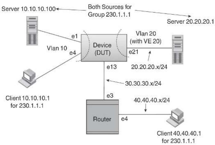
flowchart
graph TD
A["Server 10.10.10.100"] -->|e1| B["Device (DUT)"]
C["Client 10.10.10.1 for 230.1.1.1"] -->|e4| B
B -->|e21| D["Vlan 20 (with VE 20)"]
B -->|e13| E["Router"]
E -->|e3| B
E -->|e4| F["Client 40.40.40.1 for 230.1.1.1"]
B -->|e20.20.x/24| G["Server 20.20.20.1"]
B -->|30.30.30.x/24| H["Client 40.40.40.1 for 230.1.1.1"]
B -->|Both Sources for Group 230.1.1.1| I["Server 10.10.10.100"]
CLI commands
The following are the CLI commands for the configuration example shown in Figure 124 and Figure 125.
- On the device, configure IGMP Snooping on VLAN 10.
PowerConnect {config-vif-20}
PowerConnect(config)#interface e 13
PowerConnect (config-if-e1000-13)↓ip address 30.30.30.10/24
PowerConnect(config-if-ol000-13)tip pim
3. Configure the neighboring device.
PowerConnect(config)#ip route 20.20.20.0 255.255.255.0 30.30.30.10
PowerConnect(config)#router pim
PowerConnect {config-pim-router} exit
PowerConnect (config) #interface ethernet 3
PowerConnect (config-if-e1000-3) 4ip address 30.30.30.20/24
PowerConnect(config-if-e1000-3)#ip pim
PowerConnect{config-if-e1000-3}#interface ethernet 4
PowerConnect(config-if-e1000-4)hip address 40.40.40.20/24
PowerConnect{config-if-e1000-4}#ip pim
Table 143 lists the individual Dell PowerConnect switches and the IP features they support.
TABLE 143 Supported IP features
| Feature PowerConnect B-Series FCX | |
| BootP/DHCP relay Yes | |
| Specifying which IP address will be included in a DHCP/BootP reply packet | Yes |
| DHCP Server Yes | |
| DHCP Client-Based Auto-Configuration Yes | |
| DHCP Client-Based Flash image Auto-update | Yes |
| DHCP assist Yes | |
| Equal Cost Multi Path (ECMP) load sharing | Yes |
| IP helper Yes | |
| Routos in hardware maximum: PowerConnect B-Series FCX – Up to 16K routes | Yes |
| Routing for directly connected IP subnets | Yes |
| Virtual Interfaces: • Up to 512 virtual interfaces | Yes |
Address Resolution Protocol (ARP) Yes
NOTE
The terms Layer 3 Switch and router are used interchangeably in this chapter and mean the same.
Basic configuration
IP is enabled by default. Basic configuration consists of adding IP addresses for Layer 3 Switches, enabling a route exchange protocol, such as the Routing Information Protocol (RIP).
If you are configuring a Layer 3 Switch, refer to "Configuring IP addresses" on page 799 to add IP addresses, then enable and configure the route exchange protocols, as described in other chapters of this guide.
If you are configuring a Layer 2 Switch, refer to "Configuring the management IP address and specifying the default gateway" on page 863 to add an IP address for management access through the network and to specify the default gateway.
The rest of this chapter describes IP and how to configure it in more detail. Use the information in this chapter if you need to change some of the IP parameters from their default values or you want to view configuration information or statistics.
Overview
Layer 2 Switches and Layer 3 Switches support Internet Protocol version 4 (IPv4) and IPv6. IP support on Layer 2 Switches consists of basic services to support management access and access to a default gateway.
Full Layer 3 support
NOTE
Full Layer 3 images are supported on PowerConnect B-Series FCX devices only.
IP interfaces
NOTE
This section describes IPv4 addresses. For information about IPv6 addresses on all other PowerConnect devices, refer to "IPv6 addressing" on page 198.
Layer 3 Switches and Layer 2 Switches allow you to configure IP addresses. On Layer 3 Switches, IP addresses are associated with individual interfaces. On Layer 2 Switches, a single IP address serves as the management access address for the entire device.
All Layer 3 Switches and Layer 2 Switches support configuration and display of IP addresses in classical subnet format (for example: 192.168.1.1 255.255.255.0) and Classless Interdomain Routing (CIDR) format (for example: 192.168.1.1/24). You can use either format when configuring IP address information. IP addresses are displayed in classical subnet format by default, but you can change the display format to CIDR. Refer to "Changing the network mask display to prefix format" on page 869.
Layer 3 Switches
Layer 3 Switches allow you to configure IP addresses on the following types of interfaces:
- Ethernet ports
• Virtual routing interfaces (used by VLANs to route among one another) - Loopback interfaces
Each IP address on a Layer 3 Switch must be in a different subnet. You can have only one interface that is in a given subnet. For example, you can configure IP addresses 192.168.1.1/24 and 192.168.2.1/24 on the same Layer 3 Switch, but you cannot configure 192.168.1.1/24 and 192.168.1.2/24 on the same Layer 3 Switch.
You can configure multiple IP addresses on the same interface.
The number of IP addresses you can configure on an individual interface depends on the Layer 3 Switch model. To display the maximum number of IP addresses and other system parameters you can configure on a Layer 3 Switch, refer to "Displaying and modifying system parameter default settings" on page 321.

flowchart
graph TD
A["Incoming Port"] --> B["Session Table"]
B --> C{Fwding Cache}
C --> D["IP Route Table"]
D --> E["ARP Cache"]
E --> F["Static ARP Table"]
F --> G["Lowest Admin. Distance"]
G --> H["RIP"]
G --> I["OSPF"]
G --> J["BGP4"]
C --> K{PBR of IP acc policy}
K --> L["Lowest Metric"]
L --> M["Mult. Equal-cost Paths"]
M --> N["Load Balancing Algorithm"]
N --> K
K --> O{Y}
O --> P["Outgoing Port"]
P --> B
O --> Q["Y"]
Q --> R["PBR of IP acc policy"]
R --> S{Y}
S --> T["Outgoing Port"]
T --> P
Figure 126 shows the following packet flow:
1. When the Layer 3 Switch receives an IP packet, the Layer 3 Switch checks for filters on the receiving interface. ^2 If a deny filter on the interface denies the packet, the Layer 3 Switch discards the packet and performs no further processing, except generating a Syslog entry and SNMP message, if logging is enabled for the filter.
-
If the IP forwarding cache does not have an entry for the packet, the Layer 3 Switch checks the IP route table for a route to the packet destination. If the IP route table has a route, the Layer 3 Switch makes an entry in the session table or the forwarding cache, and sends the route to a queue on the outgoing ports:
-
If the running config contains an IP access policy for the packet, the software makes an entry in the session table. The Layer 3 Switch uses the new session table entry to forward subsequent packets from the same source to the same destination.
- If the running-config does not contain an IP access policy for the packet, the software creates a new entry in the forwarding cache. The Layer 3 Switch uses the new cache entry to forward subsequent packets to the same destination.
The following sections describe the IP tables and caches:
• ARP cache and static ARP table
- IP route table
- IP forwarding cache
- Layer 4 session table
The software enables you to display these tables. You also can change the capacity of the tables on an individual basis if needed by changing the memory allocation for the table.
ARP cache and static ARP table
The ARP cache contains entries that map IP addresses to MAC addresses. Generally, the entries are for devices that are directly attached to the Layer 3 Switch.
An exception is an ARP entry for an interface-based static IP route that goes to a destination that is one or more router hops away. For this type of entry, the MAC address is either the destination device MAC address or the MAC address of the router interface that answered an ARP request on behalf of the device, using proxy ARP.
ARP cache
The ARP cache can contain dynamic (learned) entries and static (user-configured) entries. The software places a dynamic entry in the ARP cache when the Layer 3 Switch learns a device MAC address from an ARP request or ARP early from the device.
The software places an entry from the static ARP table into the ARP cache when the entry interface comes up.
Here is an example of a static ARP entry.
| Index | IP Address | MAC Address | Port |
| 1 | 207.95.6.111 | 0800.093b.d210 | 1/1 |
Each entry lists the information you specified when you created the entry.
To display ARP entries, refer to the following sections:
• "Displaying the ARP cache" on page 874 - Layer 3 Switch
- "Displaying the static ARP table" on page 876 - Layer 3 Switch only
• "Displaying ARP entries" on page 884 - Layer 2 Switch
To configure other ARP parameters, refer to the following sections:
- "Configuring ARP parameters" on page 810 - Layer 3 Switch only
To increase the size of the ARP cache and static ARP table, refer to the following:
- For dynamic entries, refer to the section "Displaying and modifying system parameter default settings" on page 321. The
parameter controls the ARP cache size. - Static entries, "Changing the maximum number of entries the static ARP table can hold" on page 814 (Layer 3 Switches only). The
parameter controls the static ARP table size.
IP route table
The IP route table contains paths to IP destinations.
NOTE
Layer 2 Switches do not have an IP route table. A Layer 2 Switch sends all packets addressed to another subnet to the default gateway, which you specify when you configure the basic IP information on the Layer 2 Switch.
The IP route table can receive the paths from the following sources:
Overview
| Destination | NetMask | Gateway | Port | Cost | Type |
| 1.1.0.0 | 255.255.0.0 | 99.1.1.2 | 1/1 | 2 | R |
Each IP route table entry contains the destination IP address and subnet mask and the IP address of the next-hop router interface to the destination. Each entry also indicates the port attached to the destination or the next-hop to the destination, the route IP metric (cost), and the type. The type indicates how the IP route table received the route:
- To display the IP route table, refer to "Displaying the IP route table" on page 878 (Layer 3 Switch only).
- To configure a static IP route, refer to "Configuring static routes" on page 819 (Layer 3 Switch only).
- To clear a route from the IP route table, refer to "Clearing IP routes" on page 880 (Layer 3 Switch only).
- To increase the size of the IP route table for learned and static routes, refer to the section "Displaying and modifying system parameter default settings" on page 321:
- For learned routes, modify the
parameter. - For static routes, modify the
parameter.
IP forwarding cache
The IP forwarding cache provides a fast-path mechanism for forwarding IP packets. The cache contains entries for IP destinations. When a Layer 3 Switch has completed processing and addressing for a packet and is ready to forward the packet, the device checks the IP forwarding cache for an entry to the packet destination:
- If the cache contains an entry with the destination IP address, the device uses the information in the entry to forward the packet out the ports listed in the entry. The destination IP address is the address of the packet final destination. The port numbers are the ports through which the destination can be reached.
- If the cache does not contain an entry and the traffic does not qualify for an entry in the session table instead, the software can create an entry in the forwarding cache.
NOTE
You cannot add static entries to the IP forwarding cache, although you can increase the number of entries the cache can contain. Refer to the section "Displaying and modifying system parameter default settings" on page 321.
Layer 4 session table
The Layer 4 session provides a fast path for forwarding packets. A session is an entry that contains complete Layer 3 and Layer 4 information for a flow of traffic. Layer 3 information includes the source and destination IP addresses. Layer 4 information includes the source and destination TCP and UDP ports. For comparison, the IP forwarding cache contains the Layer 3 destination address but does not contain the other source and destination address information of a Layer 4 session table entry.
The Layer 2 Switch or Layer 3 Switch selects the session table instead of the IP forwarding table for fast-path forwarding for the following features:
• Layer 4 Quality-of-Service (QoS) policies
- IP access policies
To increase the size of the session table, refer to the section "Displaying and modifying system parameter default settings" on page 321. The ip-qos-session parameter controls the size of the session table.
IP route exchange protocols
Layer 3 Switches support the following IP route exchange protocols:
- Routing Information Protocol (RIP)
- Open Shortest Path First (OSPF)
• Border Gateway Protocol version 4 (BGP4)
All these protocols provide routes to the IP route table. You can use one or more of these protocols, in any combination. The protocols are disabled by default. For configuration information, refer to the following:
NOTE
Layer 2 Switches support IGMP and can forward IP multicast packets. Refer to Chapter 22, "Configuring IP Multicast Traffic Reduction for PowerConnect B-Series FCX Switches".
IP interface redundancy protocols
You can configure a Layer 3 Switch to back up an IP interface configured on another Layer 3 Switch. If the link for the backed up interface becomes unavailable, the other Layer 3 Switch can continue service for the interface. This feature is especially useful for providing a backup to a network default gateway.
Layer 3 Switches support the following IP interface redundancy protocols:
- Virtual Router Redundancy Protocol (VRRP) - A standard router redundancy protocol based on RFC 2338. You can use VRRP to configure Layer 3 Switches and third-party routers to back up IP interfaces on other Layer 3 Switches or third-party routers.
- Virtual Router Redundancy Protocol Extended (VRRPE) – A Dell extension to standard VRRP that adds additional features and overcomes limitations in standard VRRP. You can use VRRPE only on Layer 3 Switches.
For configuration information, refer to the Chapter 31, "Configuring VRRP and VRRPE".
Access Control Lists and IP access policies
Layer 3 Switches provide two mechanisms for filtering IP traffic:
- Access Control Lists (ACLs)
- IP access policies
Both methods allow you to filter packets based on Layer 3 and Layer 4 source and destination information.
ACLs also provide great flexibility by providing the input to various other filtering mechanisms such as route maps, which are used by BGP4.
ID access policies allow you to configure OnS based on sessions (I over A traffic flows)
- Multicast protocols:
- Internet Group Membership Protocol (IGMP) – refer to “Changing global IP multicast parameters” on page 729
- Protocol Independent Multicast Dense (PIM-DM) – refer to "PIM Dense" on page 733
- Protocol Independent Multicast Sparse (PIM-SM) – refer to "PIM Sparse" on page 742
- Router redundancy protocols:
- Virtual Router Redundancy Protocol Extended (VRRPE) – refer to Chapter 31, "Configuring VRRP and VRRPE"
- Virtual Router Redundancy Protocol (VRRP) – refer to Chapter 31, "Configuring VRRP and VRRPE"
The following tables list the Layer 3 Switch IP parameters, their default values, and where to find configuration information.
NOTE
For information about parameters in other protocols based on IP, such as RIP, OSPF, and so on, refer to the configuration chapters for those protocols.
When parameter changes take effect
Most IP parameters described in this chapter are dynamic. They take effect immediately, as soon as you enter the CLI command or select the Web Management Interface option. You can verify that a dynamic change has taken effect by displaying the running-config. To display the running-config, enter the show running-config or write terminal command at any CLI prompt. (You cannot display the running-config from the Web Management Interface.)
To save a configuration change permanently so that the change remains in effect following a system reset or software reload, save the change to the startup-config file:
- To save configuration changes to the startup-config file, enter the write memory command from the Privileged EXEC level of any configuration level of the CLI.
- To save the configuration changes using the Web Management Interface, select the Save link at the bottom of the dialog. Select Yes when prompted to save the configuration change to the
TABLE 144 IP global parameters - Layer 3 Switches
| Parameter Description Default See page... | |||
| IP state The Internet Protocol, version 4 Enabled | NOTE: You cannot disable IP. | n/a | |
| IP address and mask notation | Format for displaying an IP address and its network mask information. You can enable one of the following:Class-based format; example: 192.168.1.1255.255.255.0Classless Interdomain Routing (CIDR) format; example: 192.168.1.1/24 | Class-basedNOTE: Changing this parameter affects the display of IP addresses, but you can enter addresses In either format regardless of the display setting. | page 869 |
| Router ID The value that routers use to identify themselves to other routers when exchanging route information. OSPF and BGP4 use router IDs to identify routers. RIP does not use the router ID. | The IP address configured on the lowest-numbered loopback interface.If no loopback interface is configured, then the lowest-numbered IP address configured on the device. | page 809 | |
| Maximum Transmission Unit (MTU) | The maximum length an Ethernet packet can be without being fragmented. | 1500 bytes for Ethernet II encapsulation1492 bytes for SNAP encapsulation | page 807 |
| Address Resolution Protocol (ARP) | A standard IP mechanism that routers use to learn the Media Access Control (MAC) address of a device on the network. The router sends the IP address of a device in the ARP request and receives the device MAC address in an ARP reply. | Enabled page 810 | |
| Time to Live (TTL) | The maximum number of routers (hops) through which a packet can pass before being discarded. Each router decreases a packet TTL by 1 before forwarding the packet. If decreasing the TTL causes the TTL to be 0, the router drops the packet instead of forwarding it. | 64 hops page 815 | |
| Directed broadcast forwarding | A directed broadcast is a packet containing all ones (or in some cases, all zeros) in the host portion of the destination IP address. When a router forwards such a broadcast, it sends a copy of the packet out each of its enabled IP interfaces.NOTE: You also can enable or disable this parameter on an individual interface basis.Refor to Table 145 on page 796. | Disabled page 815 | |
| Directed broadcast mode | The packet format the router treats as a directed broadcast. The following formats can be directed broadcast:All ones in the host portion of the packet destination address.All zeroes in the host portion of the packet destination address. | All onesNOTE: If you enable all-zerosc directed broadcasts, all-ones directed broadcasts remain enabled. | page 817 |
| Source-routed packet forwarding | A source-routed packet contains a list of IP addresses through which the packet must pass to reach its destination. | Enabled page 816 | |
| Internet Control Message Protocol (ICMP) messages | The Layer 3 Switch can send the following types of ICMP messages:Echo messages (ping messages)Destination Unreachable messages | Enabled page 817 | |
| ICMP Router Discovery Protocol (IRDP) | An IP protocol a router can use to advertise the IP addresses of its router interfaces to directly attached hosts. You can enable or disable the | Disabled page 832 | |
| Parameter | Description | Default | See page... |
| Static RARP entries | An IP address you place in the RARP table for RARP requests from hosts.NOTE: You must enter the RARP entries manually. The Layer 3 Switch does not have a mechanism for learning or dynamically generating RARP entries. | No entries page 836 | |
| Maximum BootP relay hops | The maximum number of hops away a BootP server can be located from a router and still be used by the router clients for network booting. | Four page 840 | |
| Domain name for Domain Name Server (DNS) resolver | A domain name {example: brocade,router.com} you can use in place of an IP address for certain operations such as IP pings, trace routes, and Telnet management connections to the router. | None configured page 803 | |
| DNS default gateway addresses | A list of gateways attached to the router through which clients attached to the router can reach DNSs. | None configured page 803 | |
| IP load sharing A Dell feature that enables the router to balance traffic to a specific destination across multiple equal-cost paths.IP load sharing uses a hashing algorithm based on the source IP address, destination IP address, and protocol field in the IP header.NOTE: Load sharing is sometimes called Equal Cost Multi Path (ECMP). | Enabled page 829 | ||
| Maximum IP load sharing paths | The maximum number of equal-cost paths across which the Layer 3 Switch is allowed to distribute traffic. | Four page 832 | |
| Origination of default routes | You can enable a router to originate default routes for the following route exchange protocols, on an individual protocol basis:RIPOSPF | Disabled page 915 | page 957page 1010 |
IP interface parameters - Layer 3 Switches
Table 145 lists the interface-level IP parameters for Layer 3 Switches.
TABLE 145 IP interface parameters - Layer 3 Switches
| Parameter Description Default See page... | |||
| IP state The Internet Protocol, version 4 Enabled | NOTE: You cannot disable IP. | n/a | |
| IP address A Layer 3 network interface addressNOTE: Layer 2 Switches have a single IP address used for management access to the entire device. Layer 3 Switches have separable IP addresses on Individual Interfaces. | None configured ^1 | page 799 | |
| Encapsulation type The format of the packets in which the router encapsulates IP datagrams. The encapsulation format can be one of the following:Ethernet IISNAP | Ethernet II | page 806 | |
| Maximum Transmission Unit (MTU) | The maximum length (number of bytes) of an encapsulated IP datagram the router can forward. | 1500 for Ethernet II encapsulated packets1492 for SNAP encapsulated packets | page 808 |
| ARP age | Locally overrides the global setting. Refer to Table 144 on page 793. | Ten minutes | page 812 |
| Metric | A numeric cost the router adds to RIP routes learned on the interface. This parameter applies only to RIP routes. | 1 (one) | page 910 |
| Directed broadcast forwarding | Locally overrides the global setting. Refer to Table 144 on page 793. | Disabled | page 815 |
| ICMP Router Discovery Protocol (IRDP) | Locally overrides the global IRDP settings. Refer to Table 144 on page 793. | Disabled | page 834 |
TABLE 145 IP interface parameters - Layer 3 Switches (Continued)
| Parameter Description Default See page... | ||
| DHCP Server All PowerConnect devices can be configured to function as DHCP servers. | Disabled page 841 | |
| UDP broadcast forwarding | The router can forward UDP broadcast packets for UDP applications such as BootP. By forwarding the UDP broadcasts, the router enables clients on one subnet to find servers attached to other subnets.NOTE: To completely enable a client UDP application request to find a server on another subnet, you must configure an IP helper address consisting of the server IP address or the directed broadcast address for the subnet that contains the server. See the next row. | The router helps forward page 837 broadcasts for the following UDP application protocols:bootpsdnsnetbios-dgmnetbios-nstacacsutpttime |
| IP helper address The IP address of a UDP application server (such as a BootP or DHCP server) or a directed broadcast address. IP helper addresses allow the router to forward requests for certain UDP applications from a client on one subnet to a server on another subnet. | None configured page 838 | |
- Some devices have a factory default, such as 209.157.22.154, used for troubleshooting during installation. For Layer 3 Switches, the address is on module 1 port 1 (or 1/1).
Basic IP parameters and defaults - Layer 2 Switches
IP is enabled by default. The following tables list the Layer 2 Switch IP parameters, their default values, and where to find configuration information.
NOTE
Layer 2 Switches also provide IP multicast forwarding, which is enabled by default.
TABLE 146 IP global parameters - Layer 2 Switches
| Parameter Description Default See page... | |||
| IP address and mask notation | Format for displaying an IP address and its network mask information. You can enable one of the following:Class-based format; example: 192.168.1.1255.255.255.0Classless Interdomain Routing (CIDR) format; example: 192.168.1.1/24 | Class-basedNOTE: Changing this parameter affects the display of IP addresses, but you can enter addresses in either format regardless of the display setting. | page 869 |
| IP address A Layer 3 network interface addressNOTE: Layer 2 Switches have a single IP address used for management access to the entire device. Layer 3 Switches have separate IP addresses on individual interfaces. | None configured ^1 | page 863 | |
| Default gateway | The IP address of a locally attached router (or a router attached to the Layer 2 Switch by bridges or other Layer 2 Switches). The Layer 2 Switch and clients attached to it use the default gateway to communicate with devices on other subnets. | None configured page 863 | |
| Address Resolution Protocol (ARP) | A standard IP mechanism that networking devices use to learn the Media Access Control (MAC) address of another device on the network. The Layer 2 Switch sends the IP address of a device in the ARP request and receives the device MAC address in an ARP reply. | EnabledNOTE: You cannot disable ARP. | n/a |
| ARP age The amount of time the device keeps a MAC address learned through ARP in the device ARP cache. The device resets the timer to zero each time the ARP entry is refreshed and removes the entry if the timer reaches the ARP age. | Ten minutesNOTE: You cannot change the ARP age on Layer 2 Switches. | n/a | |
| Time to Live (TTL) | The maximum number of routers (hops) through which a packet can pass before being discarded. | 64 hops page 865 | |
TABLE 146 IP global parameters - Layer 2 Switches (Continued)
| Parameter Description | Default | See page... |
| DHCP gateway stamp | The device can assist DHCP/BootP Discovery packets from one subnet to reach DHCP/BootP servers on a different subnet by placing the IP address of the router interface that forwards the packet in the packet Gateway field.You can specify up to 32 gateway lists. A gateway list contains up to oight gateway IP addresses. You activate DHCP assistance by associating a gateway list with a port.When you configure multiple IP addresses in a gateway list, the Layer 2 Switch inserts the addresses into the DHCP Discovery packets in a round robin fashion. | None configured page 868 |
| DHCP Client-Based Auto-Configura tion | Allows the switch to obtain IP addresses from a DHCP host automatically, for either a specified (leased) or infinite period of time. | Enabled page 854 |
- Some devices have a factory default, such as 209.157.22.154, used for troubleshooting during installation. For Layer 3 Switches, the address is on port 1 (or 1/1).
Interface IP parameters - Layer 2 Switches
Table 147 lists the interface-level IP parameters for Layer 2 Switches.
TABLE 147 Interface IP parameters - Layer 2 Switches
| Parameter Description Default See page... | ||
| DHCP gateway stamp | You can configure a list of DHCP stamp addresses for a port. When the port receives a DHCP/BootP Discovery packet from a client, the port places the IP addresses in the gateway list into the packet Gateway field. | None configured page 868 |
• Virtual routing interface (also called a Virtual Ethernet or "VE")
- Loopback interface
By default, you can configure up to 24 IP addresses on each interface.
You can increase this amount to up to 128 IP subnet addresses per port by increasing the size of the ip-subnet-port table.
Refer to the section "Displaying and modifying system parameter default settings" on page 321.
NOTE
Once you configure a virtual routing interface on a VLAN, you cannot configure Layer 3 interface parameters on individual ports. Instead, you must configure the parameters on the virtual routing interface itself.
Dell PowerConnect devices support both classical IP network masks (Class A, B, and C subnet masks, and so on) and Classless Interdomain Routing (CIDR) network prefix masks:
- To enter a classical network mask, enter the mask in IP address format. For example, enter "209.157.22.99 255.255.255.0" for an IP address with a Class-C subnet mask.
- To enter a prefix network mask, enter a forward slash (/) and the number of bits in the mask immediately after the IP address. For example, enter "209.157.22.99/24" for an IP address that has a network mask with 24 significant bits (ones).
By default, the CLI displays network masks in classical IP address format (example: 255.255.255.0). You can change the display to prefix format. Refer to "Changing the network mask display to prefix format" on page 869.
Assigning an IP address to an Ethernet port
To assign an IP address to port 1/1, enter the following commands.
PowerConnect(config)# interface ethernet 1/1 PowerConnect(config-if-1/1)# ip address 192.45.6.1 255.255.255.0
You also can enter the IP address and mask in CIDR format, as follows.
PowerConnect(config-if-1/1)# ip address 192.45.6.1/24
NOTE
The ospf-passive option disables adjacency formation but does not disable advertisement of the interface into OSPF. To disable advertisement in addition to disabling adjacency formation, you must use the ospf-ignore option.
Use the secondary parameter if you have already configured an IP address within the same subnet on the interface.
NOTE
When you configure more than one address in the same subnet, all but the first address are secondary addresses and do not form OSPF adjacencies.
NOTE
All physical IP interfaces on Layer 3 devices share the same MAC address. For this reason, if more than one connection is made between two devices, one of which is a Layer 3 device, Dell recommends the use of virtual interfaces. It is not recommended to connect two or more physical IP interfaces between two routers.
Assigning an IP address to a loopback interface
Loopback interfaces are always up, regardless of the states of physical interfaces. They can add stability to the network because they are not subject to route flap problems that can occur due to unstable links between a Layer 3 Switch and other devices. You can configure up to eight loopback interfaces on a Chassis Layer 3 Switch. You can configure up to four loopback interfaces on a Compact Layer 3 Switch.
You can add up to 24 IP addresses to each loopback interface.
NOTE
If you configure the Layer 3 Switch to use a loopback interface to communicate with a BGP4 neighbor, you also must configure a loopback interface on the neighbor and configure the neighbor to use that loopback interface to communicate with the Layer 3 Switch. Refer to "Adding a loopback interface" on page 993.
Assigning an IP address to a virtual interface
A virtual interface is a logical port associated with a Layer 3 Virtual LAN (VLAN) configured on a Layer 3 Switch. You can configure routing parameters on the virtual interface to enable the Layer 3 Switch to route protocol traffic from one Layer 3 VLAN to the other, without using an external router. ^1
You can configure IP routing interface parameters on a virtual interface. This section describes how to configure an IP address on a virtual interface. Other sections in this chapter that describe how to configure interface parameters also apply to virtual interfaces.
NOTE
The Layer 3 Switch uses the lowest MAC address on the device (the MAC address of port 1 or 1/1) as the MAC address for all ports within all virtual interfaces you configure on the device.
To add a virtual interface to a VLAN and configure an IP address on the interface, enter commands such as the following.
PowerConnect(config)# vlan 2 name IP-Subnet_1.1.2.0/24
PowerConnect(config-vlan-2)# untag ethernet 1 to 4
PowerConnect(config-vlan-2)# router-interface vel
PowerConnect(config-vlan-2)# interface vel
PowerConnect(config-vif-1)# ip address 1.1.2.1/24
The first two commands in this example create a Layer 3 protocol-based VLAN name
"IP-Subnet_1.1.2.0/24" and add a range of untagged ports to the VLAN. The router-interface command creates virtual interface 1 as the routing interface for the VLAN.
Syntax: router-interface ve
The
When configuring virtual routing interfaces on a device, you can specify a number from 1 through 4095. However, the total number of virtual routing interfaces that are configured must not exceed the system-max limit of 512. For more information on the number of virtual routing interfaces supported, refer to "Allocating memory for more VLANs or virtual routing interfaces" on page 476.
The last two commands change to the interface configuration level for the virtual interface and
Configuration limitations and feature limitations
- When configuring IP Follow, the primary virtual routing interface should not have ACL or DoS Protection configured. It is recommended that you create a dummy virtual routing interface as the primary and use the IP-follow virtual routing interface for the network.
• Global Policy Based Routing is not supported when IP Follow is configured.
• IPv6 is not supported with ip-follow.
• PowerConnect devices support ip-follow with OSPF and VRRP protocols only.
Configuration syntax
Configure IP Follow by entering commands such as the following.
PowerConnect(config)# vlan 2 name IP Subnet_1.1.2.0/24
PowerConnect(config-vlan-2)# urlag ethernet 1 to 4
PowerConnect(config-vlan-2)# router-interface ve1
PowerConnect(config-vlan-2)# interface ve 1
PowerConnect(config-vif-1)# ip address 10.10.2.1/24
PowerConnect(config-vif-1)# interface ve 2
PowerConnect(config-vif-2)# ip follow ve 1
PowerConnect(config-vif-2)# interface ve 3
PowerConnect(config-vif-3)# ip follow ve 1
Syntax: [no] ip follow ve
For
Use the no form of the command to disable the configuration.
Virtual routing interface 2 and 3 do not have their own IP subnet address, but are sharing the IP address of virtual routing interface 1.
Deleting an IP address
To delete an IP address, enter a command such as the following.
PowerConnect{config-if-e1000-1}# no ip address 1.1.2.1
This command deletes IP address 1.1.2.1. You do not need to enter the subnet mask.
For example, if the domain "ds.company.com" is defined on a Layer 2 Switch or Layer 3 Switch and you want to initiate a ping to "mary". You need to reference only the host name instead of the host name and its domain name. For example, you could enter the following command to initiate the ping.
U:> ping mary
The Layer 2 Switch or Layer 3 Switch qualifies the host name by appending a domain name. For example, mary.ds1.company.com. This qualified name is sent to the DNS server for resolution. If there are four DNS servers configured, it is sent to the first DNS server. If the host name is not resolved, it is sent to the second DNS server. If a match is found, a response is sent back to the client with the host IP address. If no match is found, an "unknown host" message is returned. (Refer to Figure 127.)
FIGURE 127 DNS resolution with one domain name
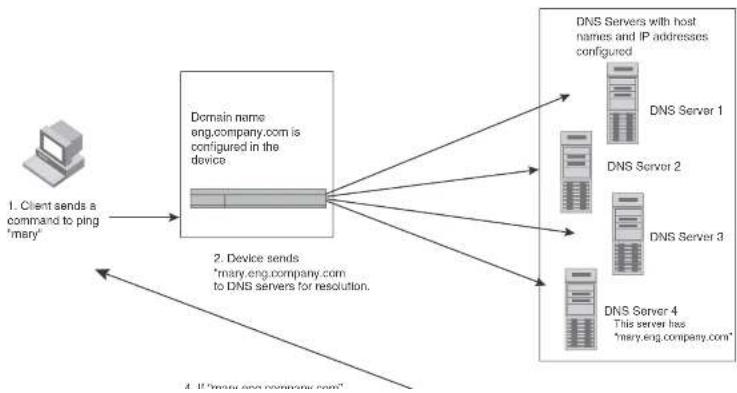
flowchart
graph TD
A["Client sends a command to ping 'mary'"] --> B["Domain name eng.company.com is configured in the device"]
B --> C["Device sends 'Mary.eng.company.com to DNS servers for resolution'"]
C --> D["DNS Servers with host names and IP addresses configured"]
D --> E["DNS Server 1"]
D --> F["DNS Server 2"]
D --> G["DNS Server 3"]
D --> H["DNS Server 4"]
H --> I["This server has "Mary.eng.company.com""]
Defining DNS server addresses
You can configure the Dell PowerConnect device to recognize up to four DNS servers. The first entry serves as the primary default address. If a query to the primary address fails to be resolved after three attempts, the next DNS address is queried (also up to three times). This process continues for each defined DNS address until the query is resolved. The order in which the default DNS addresses are polled is the same as the order in which you enter them.
To define DNS servers, enter a command such as the following.
PowerConnect(config)# ip dns server-address 209.157.22.199 205.96.7.15 208.95.7.25 201.98.7.15
Syntax: [no] ip dns server-address
In this example, the first IP address entered becomes the primary DNS address and all others are secondary addresses. Because IP address 201.98.7.15 is the last address listed, it is also the last address consulted to resolve a query.
Defining a domain list
If you want to use more than one domain name to resolve host names, you can create a list of domain names. For example, enter the commands such as the following.
PowerConnect(config)# ip dns domain-list company.com PowerConnect(config)# ip dns domain-list ds.company.com PowerConnect(config)# ip dns domain-list hw_company.com PowerConnect(config)# ip dns domain-list qa_company.com PowerConnect(config)#
The domain names are tried in the order you enter them
Syntax: [no] ip dns domain-list
Using a DNS name to initiate a trace route
Suppose you want to trace the route from a Layer 3 Switch to a remote server identified as NYC02 on domain newyork.com. Because the NYC02@ds1.newyork.com domain is already defined on the
NOTE
In the previous example, 209.157.22.199 is the IP address of the domain name server (default DNS gateway address), and 209.157.22.80 represents the IP address of the NYC02 host.
Configuring packet parameters
You can configure the following packet parameters on Layer 3 Switches. These parameters control how the Layer 3 Switch sends IP packets to other devices on an Ethernet network. The Layer 3 Switch always places IP packets into Ethernet packets to forward them on an Ethernet port.
- Encapsulation type - The format for the Layer 2 packets within which the Layer 3 Switch sends IP packets.
- Maximum Transmission Unit (MTU) – The maximum length of IP packet that a Layer 2 packet can contain. IP packets that are longer than the MTU are fragmented and sent in multiple Layer 2 packets. You can change the MTU globally or an individual ports:
- Global MTU - The default MTU value depends on the encapsulation type on a port and is
1500 bytes for Ethernet II encapsulation and 1492 bytes for SNAP encapsulation. - Port MTU - A port default MTU depends on the encapsulation type enabled on the port.
Changing the encapsulation type
The Layer 3 Switch encapsulates IP packets into Layer 2 packets, to send the IP packets on the network. (A Layer 2 packet is also called a MAC layer packet or an Ethernet frame.) The source address of a Layer 2 packet is the MAC address of the Layer 3 Switch interface sending the packet. The destination address can be one of the following:
- The MAC address of the IP packet destination. In this case, the destination device is directly connected to the Layer 3 Switch.
- The MAC address of the next-hop gateway toward the packet destination.
• An Ethernet broadcast address.
The entire IP packet, including the source and destination address and other control information and the data, is placed in the data portion of the Laver 2 packet. Typically, an Ethernet network
Changing the Maximum Transmission Unit (MTU)
The Maximum Transmission Unit (MTU) is the maximum length of IP packet that a Layer 2 packet can contain. IP packets that are longer than the MTU are fragmented and sent in multiple Layer 2 packets. You can change the MTU globally or on individual ports.
The default MTU is 1500 bytes for Ethernet II packets and 1492 for Ethernet SNAP packets.
MTU enhancements
Dell PowerConnect devices contain the following enhancements to jumbo packet support:
- Hardware forwarding of Layer 3 jumbo packets - Layer 3 IP unicast jumbo packets received on a port that supports the frame MTU size and forwarded to another port that also supports the frame MTU size are forwarded in hardware. Previous releases support hardware forwarding of Layer 2 jumbo frames only.
- ICMP unreachable message if a frame is too large to be forwarded – If a jumbo packet has the Do not Fragment (DF) bit set, and the outbound interface does not support the packet MTU size, the Dell PowerConnect device sends an ICMP unreachable message to the device that sent the packet.
NOTE
These enhancements apply only to transit traffic forwarded through the Dell PowerConnect device.
Configuration considerations for increasing the MTU
- The MTU command is applicable to VEs and physical IP interfaces. It applies to traffic routed between networks.
- You cannot use this command to set Layer 2 maximum frame sizes per interface. The global jumbo command causes all interfaces to accept Layer 2 frames.
- When you increase the MTU size of a port, the increase uses system resources. Increase the MTU size only on the ports that need it. For example, if you have one port connected to a server that uses jumbo frames and two other ports connected to clients that can support the jumbo frames, increase the MTU only on those three ports. Leave the MTU size on the other ports at the default value (1500 bytes). Globally increase the MTU size only if needed.
You can increase the MTU size to accommodate jumbo packet sizes up to up to 10,232 bytes in an IronStack. Devices that are not part of an IronStack support up to 10,240 bytes.
To globally enable jumbo support on all ports of a PowerConnect device, enter commands such as the following.
PowerConnect(config)# jumbo
PowerConnect(config)# write memory
PowerConnect(config)# end
PowerConnect# reload
Syntax: [no] jumbo
NOTE
You must save the configuration change and then reload the software to enable jumbo support.
Changing the MTU on an individual port
By default, the maximum Ethernet MTU sizes are as follows:
• 1500 bytes - The maximum for Ethernet II encapsulation
• 1492 bytes - The maximum for SNAP encapsulation
When jumbo mode is enabled, the maximum Ethernet MTU sizes are as follows:
• 10,240 bytes – The maximum for Ethernet II encapsulation
• 10,240 bytes - The maximum for SNAP encapsulation
NOTE
If you set the MTU of a port to a value lower than the global MTU and from 576 through 1499, the port fragments the packets. However, if the port MTU is exactly 1500 and this is larger than the global MTU, the port drops the packets.
NOTE
You must save the configuration change and then reload the software to enable jumbo support.
To change the MTU for interface 1/5 to 1000, enter the following commands.
Path MTU discovery (RFC 1191) support
When the Dell PowerConnect device receives an IP packet that has its Do not Fragment (DF) bit set, and the packet size is greater than the MTU value of the outbound interface, then the Dell PowerConnect device returns an ICMP Destination Unreachable message to the source of the packet, with the Code indicating "fragmentation needed and DF set". The ICMP Destination Unreachable message includes the MTU of the outbound interface. The source host can use this information to help determine the maximum MTU of a path to a destination.
RFC 1191 is supported on all interfaces.
Changing the router ID
In most configurations, a Layer 3 Switch has multiple IP addresses, usually configured on different interfaces. As a result, a Layer 3 Switch identity to other devices varies depending on the interface to which the other device is attached. Some routing protocols, including Open Shortest Path First (OSPF) and Border Gateway Protocol version 4 (BGP4), identify a Layer 3 Switch by just one of the IP addresses configured on the Layer 3 Switch, regardless of the interfaces that connect the Layer 3 Switches. This IP address is the router ID.
NOTE
Routing Information Protocol (RIP) does not use the router ID.
NOTE
If you change the router ID, all current BGP4 sessions are cleared.
By default, the router ID on a Layer 3 Switch is one of the following:
- If the router has loopback interfaces, the default router ID is the IP address configured on the lowest numbered loopback interface configured on the Layer 3 Switch. For example, if you configure loopback interfaces 1, 2, and 3 as follows, the default router ID is 9.9.9.9/24:
- Loopback interface 1, 9.9.9.9/24
- Loopback interface 2, 4.4.4.4/24
- Loopback interface 3, 1.1.1.1/24
NOTE
You can specify an IP address used for an interface on the Layer 3 Switch, but do not specify an IP address in use by another device.
Configuring ARP parameters
Address Resolution Protocol (ARP) is a standard IP protocol that enables an IP Layer 3 Switch to obtain the MAC address of another device interface when the Layer 3 Switch knows the IP address of the interface. ARP is enabled by default and cannot be disabled.
NOTE
Layer 2 Switches also support ARP. The description in "How ARP works" also applies to ARP on Layer 2 Switches. However, the configuration options described later in this section apply only to Layer 3 Switches, not to Layer 2 Switches.
How ARP works
A Layer 3 Switch needs to know a destination MAC address when forwarding traffic, because the Layer 3 Switch encapsulates the IP packet in a Layer 2 packet (MAC layer packet) and sends the Layer 2 packet to a MAC interface on a device directly attached to the Layer 3 Switch. The device can be the packet final destination or the next-hop router toward the destination.
The Layer 3 Switch encapsulates IP packets in Layer 2 packets regardless of whether the ultimate destination is locally attached or is multiple router hops away. Since the Layer 3 Switch IP route table and IP forwarding cache contain IP address information but not MAC address information, the Layer 3 Switch cannot forward IP packets based solely on the information in the route table or forwarding cache. The Layer 3 Switch needs to know the MAC address that corresponds with the IP address of either the packet locally attached destination or the next-hop router that leads to the destination.
For example, to forward a packet whose destination is multiple router hops away, the Layer 3 Switch must send the packet to the next-hop router toward its destination, or to a default route or default network route if the IP route table does not contain a route to the packet destination. In each case, the Layer 3 Switch must encapsulate the packet and address it to the MAC address of a
- If the ARP cache does not contain an entry for the destination IP address, the Layer 3 Switch broadcasts an ARP request out all its IP interfaces. The ARP request contains the IP address of the destination. If the device with the IP address is directly attached to the Layer 3 Switch, the device sends an ARP response containing its MAC address. The response is a unicast packet addressed directly to the Layer 3 Switch. The Layer 3 Switch places the information from the ARP response into the ARP cache.
ARP requests contain the IP address and MAC address of the sender, so all devices that receive the request learn the MAC address and IP address of the sender and can update their own ARP caches accordingly.
NOTE
The ARP request broadcast is a MAC broadcast, which means the broadcast goes only to devices that are directly attached to the Layer 3 Switch. A MAC broadcast is not routed to other networks. However, some routers, including Layer 3 Switches, can be configured to reply to ARP requests from one network on behalf of devices on another network. Refer to “Enabling proxy ARP” on page 812.
NOTE
If the router receives an ARP request packet that it is unable to deliver to the final destination because of the ARP timeout and no ARP response is received (the Layer 3 Switch knows of no route to the destination address), the router sends an ICMP Host Unreachable message to the source.
Rate limiting ARP packets
You can limit the number of ARP packets the Dell PowerConnect device accepts during each second. By default, the software does not limit the number of ARP packets the device can receive. Since the device sends ARP packets to the CPU for processing, if a device in a busy network receives a high number of ARP packets in a short period of time, some CPU processing might be deferred while the CPU processes the ARP packets.
To prevent the CPU from becoming flooded by ARP packets in a busy network, you can restrict the number of ARP packets the device will accept each second. When you configure an ARP rate limit, the device accepts up to the maximum number of packets you specify, but drops additional ARP packets received during the one-second interval. When a new one-second interval starts, the
NOTE
If you want to change a previously configured the ARP rate limiting policy, you must remove the previously configured policy using the no rate-limit-arp
Changing the ARP aging period
When the Layer 3 Switch places an entry in the ARP cache, the Layer 3 Switch also starts an aging timer for the entry. The aging timer ensures that the ARP cache does not retain learned entries that are no longer valid. An entry can become invalid when the device with the MAC address of the entry is no longer on the network.
The ARP age affects dynamic (learned) entries only, not static entries. The default ARP age is ten minutes. On Layer 3 Switches, you can change the ARP age to a value from 0 through 240 minutes. You cannot change the ARP age on Layer 2 Switches. If you set the ARP age to zero, aging is disabled and entries do not age out.
To globally change the ARP aging parameter to 20 minutes, enter the following command.
PowerConnect(config)# ip arp-age 20
Syntax: ip arp-age
The
To override the globally configured IP ARP age on an individual interface, enter a command such as the following at the interface configuration level.
PowerConnect(config-if-e1000-1/1) ip arp-age 30
Syntax: [no] ip arp-age
The
Enabling proxy ARP
Proxy ARP is disabled by default on Layer 3 Switches. This feature is not supported on Layer 2 Switches.
You can enable proxy ARP at the Interface level, as well as at the Global CONFIG level, of the CLI.
NOTE
Configuring proxy ARP at the Interface level overrides the global configuration.
Enabling proxy ARP globally
To enable IP proxy ARP on a global basis, enter the following command.
PowerConnect(config)# ip proxy-arp
To again disable IP proxy ARP on a global basis, enter the following command.
PowerConnect(config)# no ip proxy-arp
Syntax: [no] ip proxy-arp
Enabling IP ARP on an interface
NOTE
Configuring proxy ARP at the Interface level overrides the global configuration.
To enable IP proxy ARP on an interface, enter the following command.
PowerConnect{config}# interface ethernet 5
PowerConnect(config-if-e1000-5)# ip proxy-arp enable
To again disable IP proxy ARP on an interface, enter the following command.
PowerConnect(config)# interface ethernet 5
PowerConnect(config-if-e1000-5)# ip proxy-arp disable
Syntax: [no] ip proxy-arp enable | disable
Enabling local proxy ARP
Dell PowerConnect devices support Proxy Address Resolution Protocol (Proxy ARP), a feature that
PowerConnect(config)# interface ethernet 4
PowerConnect(config-if-e1000-4)# ip local-proxy-arp
Syntax: [no] ip local-proxy-arp
Use the no form of the command to disable Local Proxy ARP.
Creating static ARP entries
Layer 3 Switches have a static ARP table, in addition to the regular ARP cache. The static ARP table contains entries that you configure.
Static entries are useful in cases where you want to pre-configure an entry for a device that is not connected to the Layer 3 Switch, or you want to prevent a particular entry from aging out. The software removes a dynamic entry from the ARP cache if the ARP aging interval expires before the entry is refreshed. Static entries do not age out, regardless of whether the Dell PowerConnect device receives an ARP request from the device that has the entry address.
NOTE
You cannot create static ARP entries on a Layer 2 Switch.
The maximum number of static ARP entries you can configure depends on the software version running on the device. Refer to "Changing the maximum number of entries the static ARP table can hold" on page 814.
To display the ARP cache and static ARP table, refer to the following:
• To display the ARP table, refer to "Displaying the ARP cache" on page 874.
• To display the static ARP table, refer to "Displaying the static ARP table" on page 876.
To create a static ARP entry, enter a command such as the following.
PowerConnect(config)# arp 1 192.53.4.2 1245.7654.2348 ethernet 1/2
Syntax: arp
The
The six adders parameters are given the ID address of the device that has the MIO address of the
To increase the maximum number of static ARP table entries you can configure on a Layer 3 Switch, enter commands such as the following at the global CONFIG level of the CLI.
PowerConnect(config)# system-max ip-static-arp 1000
PowerConnect(config)† write memory
PowerConnect {config} # end
PowerConnect ^1 reload
NOTE
You must save the configuration to the startup-config file and reload the software after changing the static ARP table size to place the change into effect.
Syntax: system-max ip-static-arp
The
TABLE 148 Static ARP entry support
| Default maximum Configurable minimum Configurable maximum |
| PowerConnect B-Series FCX devices |
| 512 512 6000 |
Configuring forwarding parameters
The following configurable parameters control the forwarding behavior of Layer 3 Switches:
• Time-To-Live (TTL) threshold
• Forwarding of directed broadcasts
• Forwarding of source-routed packets
- Ones-based and zero-based broadcasts
All these parameters are global and thus affect all IP interfaces configured on the Layer 3 Switch.
To configure these parameters, use the procedures in the following sections.
NOTE
A less common type, the all-subnets broadcast, goes to all directly-attached subnets. Forwarding for this broadcast type also is supported, but most networks use IP multicasting instead of all-subnet broadcasting.
Forwarding for all types of IP directed broadcasts is disabled by default. You can enable forwarding for all types if needed. You cannot enable forwarding for specific broadcast types.
To enable forwarding of IP directed broadcasts, enter the following command.
PowerConnect{config}# ip directed-broadcast
Syntax: [no] ip directed-broadcast
Dell software makes the forwarding decision based on the router's knowledge of the destination network prefix. Routers cannot determine that a message is unicast or directed broadcast apart from the destination network prefix. The decision to forward or not forward the message is by definition only possible in the last hop router.
To disable the directed broadcasts, enter the following command in the CONFIG mode.
PowerConnect(config)# no ip directed-broadcast
To enable directed broadcasts on an individual interface instead of globally for all interfaces, enter commands such as the following.
PowerConnect(config)# interface ethernet 1/1
PowerConnect(config-1f-1/1)# ip directed-broadcast
Syntax: [no] ip directed-broadcast
Disabling forwarding of IP source-routed packets
A source-routed packet specifies the exact router path for the packet. The packet specifies the path by listing the IP addresses of the router interfaces through which the packet must pass on its way to the destination. The Layer 3 Switch supports both types of IP source routing:
- Strict source routing – requires the packet to pass through only the listed routers. If the Layer 3 Switch receives a strict source-routed packet but cannot reach the next hop interface specified
PowerConnect(config)# ip source-route
Enabling support for zero-based IP subnet broadcasts
By default, the Layer 3 Switch treats IP packets with all ones in the host portion of the address as IP broadcast packets. For example, the Layer 3 Switch treats IP packets with 209.157.22.255/24 as the destination IP address as IP broadcast packets and forwards the packets to all IP hosts within the 209.157.22.x subnet (except the host that sent the broadcast packet to the Layer 3 Switch).
Most IP hosts are configured to receive IP subnet broadcast packets with all ones in the host portion of the address. However, some older IP hosts instead expect IP subnet broadcast packets that have all zeros instead of all ones in the host portion of the address. To accommodate this type of host, you can enable the Layer 3 Switch to treat IP packets with all zeros in the host portion of the destination IP address as broadcast packets.
NOTE
When you enable the Layer 3 Switch for zero-based subnet broadcasts, the Layer 3 Switch still treats IP packets with all ones the host portion as IP subnet broadcasts too. Thus, the Layer 3 Switch can be configured to support all ones only (the default) or all ones and all zeroes.
NOTE
This feature applies only to IP subnet broadcasts, not to local network broadcasts. The local network broadcast address is still expected to be all ones.
To enable the Layer 3 Switch for zero-based IP subnet broadcasts in addition to ones-based IP subnet broadcasts, enter the following command.
PowerConnect(config)# ip broadcast-zero
PowerConnect(config)# write memory
PowerConnect (config) ^4 end
PowerCorporation 1, upload
NOTE
You must save the configuration and reload the software to place this configuration change into effect.
Disabling replies to broadcast ping requests
By default, Dell PowerConnect devices are enabled to respond to broadcast ICMP echo packets, which are ping requests.
To disable response to broadcast ICMP echo packets (ping requests), enter the following command.
PowerConnect(config)# no ip icmp echo broadcast-request
Syntax: [no] ip icmp echo broadcast-request
If you need to re-enable response to ping requests, enter the following command.
PowerConnect(config)# ip icmp echo broadcast-request
Disabling ICMP destination unreachable messages
By default, when a Dell PowerConnect device receives an IP packet that the device cannot deliver, the device sends an ICMP Unreachable message back to the host that sent the packet. You can selectively disable a Dell PowerConnect device response to the following types of ICMP Unreachable messages:
- Administration – The packet was dropped by the Dell PowerConnect device due to a filter or ACL configured on the device.
- Fragmentation-needed - The packet has the Do not Fragment bit set in the IP Flag field, but the Dell PowerConnect device cannot forward the packet without fragmenting it.
- Host – The destination network or subnet of the packet is directly connected to the Dell PowerConnect device, but the host specified in the destination IP address of the packet is not on the network.
- Port – The destination host does not have the destination TCP or UDP port specified in the packet. In this case, the host sends the ICMP Port Unreachable message to the Dell PowerConnect device, which in turn sends the message to the host that sent the packet.
- Protocol – The TCP or UDP protocol on the destination host is not running. This message is different from the Port Unreachable message, which indicates that the protocol is running on the host but the requested protocol port is unavailable.
-
Source-route-failure – The device received a source-routed packet but cannot locate the next-hop IP address indicated in the packet Source-Route option.
-
The administration parameter disables ICMP Unreachable (caused by Administration action) messages.
- The fragmentation-needed parameter disables ICMP Fragmentation Needed But Do not-Fragment Bit Set messages.
• The host parameter disables ICMP Host Unreachable messages.
• The port parameter disables ICMP Port Unreachable messages.
• The protocol parameter disables ICMP Protocol Unreachable messages. - The source-route-fall parameter disables ICMP Unreachable (caused by Source-Route-Failure) messages.
To disable ICMP Host Unreachable messages but leave the other types of ICMP Unreachable messages enabled, enter the following commands instead of the command shown above.
PowerConnect(config)# no ip icmp unreachable host
If you have disabled all ICMP Unreachable message types but you want to re-enable certain types, for example ICMP Host Unreachable messages, you can do so by entering the following command.
PowerConnect(config)# ip icmp unreachable host
Disabling ICMP Redirect Messages
You can disable or re-enable ICMP redirect messages. By default, a Layer 3 Switch sends an ICMP redirect message to the source of a misdirected packet in addition to forwarding the packet to the appropriate router. You can disable ICMP redirect messages on a global basis or on an individual port basis.
NOTE
The device forwards misdirected traffic to the appropriate router, even if you disable the redirect messages.
To disable ICMP redirect messages globally, enter the following command at the global CONFIG level of the CLI:
PowerConnect(config)# no ip icmp redirect
- RIP - If RIP is enabled, the Layer 3 Switch can learn about routes from the advertisements other RIP routers send to the Layer 3 Switch. If the route has a lower administrative distance than any other routes from different sources to the same destination, the Layer 3 Switch places the route in the IP route table.
- OSPF – Refer to RIP, but substitute "OSPF" for "RIP".
- BGP4 – Refer to RIP, but substitute "BGP4" for "RIP".
- Default network route – A statically configured default route that the Layer 3 Switch uses if other default routes to the destination are not available. Refer to “Configuring a default network route” on page 828.
- Statically configured route – You can add routes directly to the route table. When you add a route to the IP route table, you are creating a static IP route. This section describes how to add static routes to the IP route table.
Static route types
You can configure the following types of static IP routes:
- Standard – the static route consists of the destination network address and network mask, and the IP address of the next-hop gateway. You can configure multiple standard static routes with the same metric for load sharing or with different metrics to provide a primary route and backup routes.
- Interface-based – the static route consists of the destination network address and network mask, and the Layer 3 Switch interface through which you want the Layer 3 Switch to send traffic for the route. Typically, this type of static route is for directly attached destination networks.
- Null – the static route consists of the destination network address and network mask, and the "null0" parameter. Typically, the null route is configured as a backup route for discarding traffic if the primary route is unavailable.
Static IP route parameters
When you configure a static IP route, you must specify the following parameters:
- The administrative distance for the route – The value that the Layer 3 Switch uses to compare this route with routes from other route sources to the same destination before placing a route in the IP route table. This parameter does not apply to routes that are already in the IP route table. The default administrative distance for static IP routes is 1.
The default metric and administrative distance values ensure that the Layer 3 Switch always prefers static IP routes over routes from other sources to the same destination.
Multiple static routes to the same destination provide load sharing and redundancy
You can add multiple static routes for the same destination network to provide one or more of the following benefits:
- IP load balancing - When you add multiple IP static routes for the same destination to different next-hop gateways, and the routes each have the same metric and administrative distance, the Layer 3 Switch can load balance traffic to the routes' destination. For information about IP load balancing, refer to "Configuring IP load sharing" on page 829.
- Path redundancy – When you add multiple static IP routes for the same destination, but give the routes different metrics or administrative distances, the Layer 3 Switch uses the route with the lowest administrative distance by default, but uses another route to the same destination if the first route becomes unavailable.
Refer to the following sections for examples and configuration information:
- "Configuring load balancing and redundancy using multiple static routes to the same destination" on page 824
- "Configuring standard static IP routes and interface or null static routes to the same destination" on page 825
Static route states follow port states
IP static routes remain in the IP route table only so long as the port or virtual interface used by the route is available. If the port or virtual routing interface becomes unavailable, the software removes the static route from the IP route table. If the port or virtual routing interface becomes available
PowerConnect(config)# ip route 207.95.7.0/24 207.95.6.157
When you configure a static IP route, you specify the destination address for the route and the next-hop gateway or Layer 3 Switch interface through which the Layer 3 Switch can reach the route. The Layer 3 Switch adds the route to the IP route table. In this case, Switch A knows that 207.95.6.157 is reachable through port 1/2, and also assumes that local interfaces within that subnet are on the same port. Switch A deduces that IP interface 207.95.7.188 is also on port 1/2.
The software automatically removes a static IP route from the IP route table if the port used by that route becomes unavailable. When the port becomes available again, the software automatically re-adds the route to the IP route table.
Configuring a static IP route
To configure an IP static route with a destination address of 192.0.0.0 255.0.0.0 and a next-hop router IP address of 195.1.1.1, enter the following commands.
PowerConnect(config)# ip route 192.0.0.0 255.0.0.0 195.1.1.1
To configure a static IP route with an Ethernet port instead of a next-hop address, enter a command such as the following.
PowerConnect(config)# ip route 192.128.2.69 255.255.255.0 ethernet 4/1
The command in the previous example configures a static IP route for destination network 192.128.2.69/24. Since an Ethernet port is specified instead of a gateway IP address as the next hop, the Layer 3 Switch always forwards traffic for the 192.128.2.69/24 network to port 4/1. The command in the following example configures an IP static route that uses virtual interface 3 as its next hop.
PowerConnect(config)# ip route 192.128.2.71 255.255.255.0 ve 3
The command in the following example configures an IP static route that uses port 2/2 as its next hop.
PowerConnect(config)# ip route 192.128.2.73 255.255.255.0 ethernet 2/2
Syntax: ip route
• The sum of f_i is the sum of f_i .
If you do not want to specify a next-hop IP address, you can instead specify a port or interface number on the Layer 3 Switch. The
NOTE
The port or virtual interface you use for the static route next hop must have at least one IP address configured on it. The address does not need to be in the same subnet as the destination network.
The
NOTE
If you specify 16, RIP considers the metric to be infinite and thus also considers the route to be unreachable.
The distance
NOTE
The Layer 3 Switch will replace the static route if the it receives a route with a lower administrative distance. Refer to "Changing administrative distances" on page 1014 for a list of the default administrative distances for all types of routes.
NOTE
You can also assign the default router as the destination by entering 0.0.0.0 0.0.0.0 xxx.xxx.xxx.xxx.
Configuring a "Null" route
You can configure the Layer 3 Switch to drop IP packets to a specific network or host address by
The
The
The null0 parameter indicates that this is a null route. You must specify this parameter to make this a null route.
The
The distance
NOTE
The last two parameters are optional and do not affect the null route, unless you configure the administrative distance to be 255. In this case, the route is not used and the traffic might be forwarded instead of dropped.
Configuring load balancing and redundancy using multiple static routes to the same destination
You can configure multiple static IP routes to the same destination, for the following benefits:
- IP load sharing - If you configure more than one static route to the same destination, and the routes have different next-hop gateways but have the same metrics, the Layer 3 Switch load balances among the routes using basic round-robin. For example, if you configure two static routes with the same metrics but to different gateways, the Layer 3 Switch alternates between the two routes. For information about IP load balancing, refer to "Configuring IP load sharing" on page 829.
- Backup Routes – If you configure multiple static IP routes to the same destination, but give the routes different next-hop gateways and different metrics, the Layer 3 Switch will always use the route with the lowest metric. If this route becomes unavailable, the Layer 3 Switch will fail over
The commands in the previous example configure two static IP routes. The routes go to different next-hop gateways but have the same metrics. These commands use the default metric value (1), so the metric is not specified. These static routes are used for load sharing among the next-hop gateways.
The following commands configure static IP routes to the same destination, but with different metrics. The route with the lowest metric is used by default. The other routes are backups in case the first route becomes unavailable. The Layer 3 Switch uses the route with the lowest metric if the route is available.
PowerConnect(config)# ip route 192.128.2.69 255.255.255.0 209.157.22.1 PowerConnect(config)# ip route 192.128.2.69 255.255.255.0 192.111.10.1 2 PowerConnect(config)# ip route 192.128.2.69 255.255.255.0 201.1.1.1 3
In this example, each static route has a different metric. The metric is not specified for the first route, so the default (1) is used. A metric is specified for the second and third static IP routes. The second route has a metric of two and the third route has a metric of 3. Thus, the second route is used only of the first route (which has a metric of 1) becomes unavailable. Likewise, the third route is used only if the first and second routes (which have lower metrics) are both unavailable.
For complete syntax information, refer to "Configuring a static IP route" on page 822.
Configuring standard static IP routes and interface or null static routes to the same destination
You can configure a null0 or interface-based static route to a destination and also configure a normal static route to the same destination, so long as the route metrics are different.
When the Layer 3 Switch has multiple routes to the same destination, the Layer 3 Switch always prefers the route with the lowest metric. Generally, when you configure a static route to a destination network, you assign the route a low metric so that the Layer 3 Switch prefers the static route over other routes to the destination.
This feature is especially useful for the following configurations. These are not the only allowed configurations but they are typical uses of this enhancement:
- When you want to ensure that if a given destination network is unavailable, the Layer 3 Switch drone (forwards to the null interface) traffic for that network instead of using alternate paths to
Figure 129 shows an example of two static routes configured for the same destination network. In this example, one of the routes is a standard static route and has a metric of 1. The other static route is a null route and has a higher metric than the standard static route. The Layer 3 Switch always prefers the static route with the lower metric. In this example, the Layer 3 Switch always uses the standard static route for traffic to destination network 192.168.7.0/24, unless that route becomes unavailable, in which case the Layer 3 Switch sends traffic to the null route instead.
FIGURE 129 Standard and null static routes to the same destination network
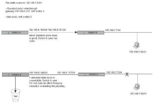
flowchart
graph TD
A["Switch A"] -->|192.168.6.186/24 192.168.6.157/24| B["Switch B"]
B --> C["Switch A"]
C -->|If standard static route is unavailable, Switch A uses the null route (in effect dropping instead of forwarding the packets).| D["Switch A"]
D --> E["Switch B"]
E --> F["Switch A"]
F --> G["Null"]
Figure 130 shows another example of two static routes. In this example, a standard static route and an interface-based static route are configured for destination network 192.168.6.0/24. The interface-based static route has a lower metric than the standard static route. As a result, the Layer 3 Switch cluster performs the interface-based route when the route is available. However, if the
FIGURE 130 Standard and interface routes to the same destination network
Two static routes to 192.168.7.0/24:
-Interface-based route through
Portfolio, with metric 1
-Standard static route through
galway 192.158.8.11, with metric 3.

flowchart
graph TD
A["Switch A"] --> B["192.168.6.188/24 PortM"]
B --> C["Switch B"]
C --> D["192.168.8.11/24"]
D --> E["Switch C"]
E --> F["Switch D"]
F --> G["Switch A uses alternate route through gateway"]
style A fill:#f9f,stroke:#333
style G fill:#ccf,stroke:#333
To configure a standard static IP route and a null route to the same network as shown in Figure 129 on page 826, enter commands such as the following.
PowerConnect(config)# ip route 192.168.7.0/24 192.168.6.157/24 1
PowerConnect(config)# ip route 192.168.7.0/24 null0 3
The first command configures a standard static route, which includes specification of the next-hop gateway. The command also gives the standard static route a metric of 1, which causes the Layer 3 Switch to always prefer this route when the route is available.
The second command configures another static route for the same destination network, but the
Configuring a default network route
The Layer 3 Switch enables you to specify a candidate default route without the need to specify the next hop gateway. If the IP route table does not contain an explicit default route (for example, 0.0,0.0/0) or propagate an explicit default route through routing protocols, the software can use the default network route as a default route instead.
When the software uses the default network route, it also uses the default network route's next hop gateway as the gateway of last resort.
This feature is especially useful in environments where network topology changes can make the next hop gateway unreachable. This feature allows the Layer 3 Switch to perform default routing even if the default network route's default gateway changes.
The feature thus differs from standard default routes. When you configure a standard default route, you also specify the next hop gateway. If a topology change makes the gateway unreachable, the default route becomes unusable.
For example, if you configure 10.10.10.0/24 as a candidate default network route, if the IP route table does not contain an explicit default route (0.0.0.0/0), the software uses the default network route and automatically uses that route's next hop gateway as the default gateway. If a topology change occurs and as a result the default network route's next hop gateway changes, the software can still use the default network route. To configure a default network route, use the following CLI method.
If you configure more than one default network route, the Layer 3 Switch uses the following algorithm to select one of the routes.
- Use the route with the lowest administrative distance.
-
If the administrative distances are equal:
-
Are the routes from different routing protocols (RIP, OSPF, or BGP4)? If so, use the route with the lowest IP address.
- If the routes are from the same routing protocol, use the route with the best metric. The meaning of "best" metric depends on the routing protocol:
- RIP – The metric is the number of hops (additional routers) to the destination. The best route is the route with the fewest hops.
To verify that the route is in the route table, enter the following command at any level of the CLI.
PowerConnect# show ip route
Total number of IP routes: 2
| Start index: 1 B:DGP D:Connected R:RIP S:Static O:OSPF *:Candidate default | |||||||
| Destination | NotMask | Gateway | Port | Cost | Type | ||
| 1 | 209.157.20.0 | 255.255.255.0 | 0.0.0.0 | 101 | 1 | D | |
| 2 | 209.157.22.0 | 255.255.255.0 | 0.0.0.0 | 4/11 | 1 | *D | |
This example shows two routes. Both of the routes are directly attached, as indicated in the Type column. However, one of the routes is shown as type "*D", with an asterisk (*). The asterisk indicates that this route is a candidate default network route.
Configuring IP load sharing
The IP route table can contain more than one path to a given destination. When this occurs, the Layer 3 Switch selects the path with the lowest cost as the path for forwarding traffic to the destination. If the IP route table contains more than one path to a destination and the paths each have the lowest cost, then the Layer 3 Switch uses IP load sharing to select a path to the destination. ^1
IP load sharing uses a hashing algorithm based on the source IP address, destination IP address, and protocol field in the IP header.
NOTE
IP load sharing is based on next-hop routing, and not on source routing.
NOTE
The term “path” refers to the next-hop router to a destination, not to the entire route to a destination. Thus, when the software compares multiple equal-cost paths, the software is comparing paths that use different next-hop routers, with equal costs, to the same destination.
In many contexts, the terms "route" and "path" mean the same thing. Most of the user documentation uses the term "route" throughout. The term "path" is used in this section to refer to an individual next-hop router to a destination, while the term "route" refers collectively to the
- Routes learned through BGP4
Administrative distance
The administrative distance is a unique value associated with each type (source) of IP route. Each path has an administrative distance. The administrative distance is not used when performing IP load sharing, but the administrative distance is used when evaluating multiple equal-cost paths to the same destination from different sources, such as RIP, OSPF and so on.
The value of the administrative distance is determined by the source of the route. The Layer 3 Switch is configured with a unique administrative distance value for each IP route source.
When the software receives multiple paths to the same destination and the paths are from different sources, the software compares the administrative distances of the paths and selects the path with the lowest distance. The software then places the path with the lowest administrative distance in the IP route table. For example, if the Layer 3 Switch has a path learned from OSPF and a path learned from RIP for a given destination, only the path with the lower administrative distance enters the IP route table.
Here are the default administrative distances on the Layer 3 Switch:
- Directly connected - 0 (this value is not configurable)
- Static IP route - 1 (applies to all static routes, including default routes and default network routes)
• Exterior Border Gateway Protocol (EBGP) - 20 - OSPF - 110
- RIP - 120
• Interior Gateway Protocol (IBGP) - 200 - Local BGP - 200
- Unknown - 255 (the router will not use this route)
Lower administrative distances are preferred over higher distances. For example, if the router receives routes for the same network from OSPF and from RIP, the router will prefer the OSPF route by default.
The source of a path cost value depends on the source of the path:
- IP static route – The value you assign to the metric parameter when you configure the route. The default metric is 1. Refer to “Configuring load balancing and redundancy using multiple static routes to the same destination” on page 824.
- RIP – The number of next-hop routers to the destination.
- OSPF - The Path Cost associated with the path. The paths can come from any combination of inter-area, intra-area, and external Link State Advertisements (LSAs).
• BGP4 – The path Multi-Exit Discriminator (MED) value.
NOTE
If the path is redistributed between two or more of the above sources before entering the IP route table, the cost can increase during the redistribution due to settings in redistribution filters.
Static route, OSPF, and BGP4 load sharing
IP load sharing and load sharing for static routes, OSPF routes, and BGP4 routes are individually configured. Multiple equal-cost paths for a destination can enter the IP route table only if the source of the paths is configured to support multiple equal-cost paths. For example, if BGP4 allows only one path with a given cost for a given destination, the BGP4 route table cannot contain equal-cost paths to the destination. Consequently, the IP route table will not receive multiple equal-cost paths from BGP4.
Table 149 lists the default and configurable maximum numbers of paths for each IP route source that can provide equal-cost paths to the IP route table. The table also lists where to find configuration information for the route source load sharing parameters.
The load sharing state for all the route sources is based on the slate of IP load sharing. Since IP load sharing is enabled by default on all Layer 3 Switches, load sharing for static IP routes, RIP routes, OSPF routes, and BGP4 routes also is enabled by default.
TABLE 149 Default load sharing parameters for route sources
| Route source | Maximum number of paths | See... |
| Default maximum number of paths |
- If the IP forwarding sharing cache contains a forwarding entry for the destination, the device uses the entry to forward the traffic.
- If the IP load forwarding cache does not contain a forwarding entry for the destination, the software selects a path from among the available equal-cost paths to the destination, then creates a forwarding entry in the cache based on the calculation. Subsequent traffic for the same destination uses the forwarding entry.
Response to path state changes
If one of the load-balanced paths to a cached destination becomes unavailable, or the IP route table receives a new equal-cost path to a cached destination, the software removes the unavailable path from the IP route table. Then the software selects a new path.Disabling or re-enabling load sharing
To disable IP load sharing, enter the following commands.
PowerConnect(config)# no ip load-sharing
Syntax: [no] ip load-sharing
Changing the maximum number of ECMP (load sharing) paths
You can change the maximum number of paths the Layer 3 Switch supports to a value from 2 through 8. Table 150 shows the maximum number of paths supported per device.
TABLE 150 Maximum number of ECMP load sharing paths per device
PowerConnect B-Series FCX
8
For optimal results, set the maximum number of paths to a value at least as high as the maximum number of equal-cost paths your network typically contains. For example, if the Layer 3 Switch you are configuring for IP load sharing has six next-hop routers, set the maximum paths value to six.
NOTE
- If you leave the feature disabled globally but enable it on individual ports, you also can configure the IRDP parameters on an individual port basis.
NOTE
You can configure IRDP parameters only an individual port basis. To do so, IRDP must be disabled globally and enabled only on individual ports. You cannot configure IRDP parameters if the feature is globally enabled.
When IRDP is enabled, the Layer 3 Switch periodically sends Router Advertisement messages out the IP interfaces on which the feature is enabled. The messages advertise the Layer 3 Switch IP addresses to directly attached hosts who listen for the messages. In addition, hosts can be configured to query the Layer 3 Switch for the information by sending Router Solicitation messages.
Some types of hosts use the Router Solicitation messages to discover their default gateway. When IRDP is enabled on the Layer 3 Switch, the Layer 3 Switch responds to the Router Solicitation messages. Some clients interpret this response to mean that the Layer 3 Switch is the default gateway. If another router is actually the default gateway for these clients, leave IRDP disabled on the Layer 3 Switch.
IRDP uses the following parameters. If you enable IRDP on individual ports instead of enabling the feature globally, you can configure these parameters on an individual port basis:
- Packet type - The Layer 3 Switch can send Router Advertisement messages as IP broadcasts or as IP multicasts addressed to IP multicast group 224.0.0.1. The packet type is IP broadcast.
- Maximum message interval and minimum message interval - When IRDP is enabled, the Layer 3 Switch sends the Router Advertisement messages every 450 - 600 seconds by default. The time within this interval that the Layer 3 Switch selects is random for each message and is not affected by traffic loads or other network factors. The random interval minimizes the probability that a host will receive Router Advertisement messages from other routers at the same time. The interval on each IRDP-enabled Layer 3 Switch interface is independent of the interval on other IRDP-enabled interfaces. The default maximum message interval is 600 seconds. The default minimum message interval is 450 seconds.
- Hold time – Each Router Advertisement message contains a hold time value. This value specifies the maximum amount of time the host should consider an advertisement to be valid until a newer advertisement arrives. When a new advertisement arrives, the hold time is reset. The hold time is always longer than the maximum advertisement internet. Therefore, if the hold
Enabling IRDP on an individual port
To enable IRDP on an individual interface and change IRDP parameters, enter commands such as the following.
PowerConnect(config)# interface ethernet 1/3
PowerConnect(config-if-1/3)# ip irdp maxadvertinterval 400
This example shows how to enable IRDP on a specific port and change the maximum advertisement interval for Router Advertisement messages to 400 seconds.
NOTE
To enable IRDP on individual ports, you must leave the feature globally disabled.
Syntax: [no] ip irdp [broadcast | multicast] [holdtime
The broadcast | multicast parameter specifies the packet type the Layer 3 Switch uses to send Router Advertisement:
- broadcast – The Layer 3 Switch sends Router Advertisement as IP broadcasts. This is the default.
- multicast – The Layer 3 Switch sends Router Advertisement as multicast packets addressed to IP multicast group 224.0.0.1.
The holdtime
The maxadvertinterval parameter specifies the maximum amount of time the Layer 3 Switch waits between sending Router Advertisements. You can specify a value from 1 to the current value of the holdtime parameter. The default is 600 seconds.
RARP is enabled by default. However, you must create a RARP entry for each host that will use the Layer 3 Switch for booting. A RARP entry consists of the following information:
- The entry number – the entry sequence number in the RARP table.
• The MAC address of the boot client. - The IP address you want the Layer 3 Switch to give to the client.
When a client sends a RARP broadcast requesting an IP address, the Layer 3 Switch responds to the request by looking in the RARP table for an entry that contains the client MAC address:
- If the RARP table contains an entry for the client, the Layer 3 Switch sends a unicast response to the client that contains the IP address associated with the client MAC address in the RARP table.
- If the RARP table does not contain an entry for the client, the Layer 3 Switch silently discards the RARP request and does not reply to the client.
How RARP Differs from BootP/DHCP
RARP and BootP/DHCP are different methods for providing IP addresses to IP hosts when they boot. These methods differ in the following ways:
- Location of configured host addresses:
- RARP requires static configuration of the host IP addresses on the Layer 3 Switch. The Layer 3 Switch replies directly to a host request by sending an IP address you have configured in the RARP table.
- The Layer 3 Switch forwards BootP and DHCP requests to a third-party BootP/DHCP server that contains the IP addresses and other host configuration information.
- Connection of host to boot source (Layer 3 Switch or BootP/DHCP server):
- RARP requires the IP host to be directly attached to the Layer 3 Switch.
- An IP host and the BootP/DHCP server can be on different networks and on different routers, so long as the routers are configured to forward ("help") the host boot request to the boot server.
- You can centrally configure other host parameters on the BootP/DHCP server, in addition
Creating static RARP entries
You must configure the RARP entries for the RARP table. The Layer 3 Switch can send an IP address in reply to a client RARP request only if create a RARP entry for that client.
To assign a static IP RARP entry for static routes on a router, enter a command such as the following.
PowerConnect(config)# rarp 1 1245.7654.2348 192.53.4.2
This command creates a RARP entry for a client with MAC address 1245.7654.2348. When the Layer 3 Switch receives a RARP request from this client, the Layer 3 Switch replies to the request by sending IP address 192.53.4.2 to the client.
Syntax: rarp
The
The
The
Changing the maximum number of static RARP entries supported
The number of RARP entries the Layer 3 Switch supports depends on how much memory the Layer 3 Switch has. To determine how many RARP entries your Layer 3 Switch can have, display the system default information using the procedure in the section "Displaying and modifying system parameter default settings" on page 321.
If your Layer 3 Switch allows you to increase the maximum number of RARP entries, you can use a procedure in the same section to do so.
NOTE
You must save the configuration to the startup-config file and reload the software after changing the
- Configure a helper adders on the interface connected to the clients. Specify the helper address to be the IP address of the application server or the subnet directed broadcast address for the IP subnet the server is in. A helper address is associated with a specific interface and applies only to client requests received on that interface. The Layer 3 Switch forwards client requests for any of the application ports the Layer 3 Switch is enabled to forward to the helper address.
Forwarding support for the following application ports is enabled by default:
- bootps (port 67)
• dns (port 53) - tftp (port 69)
• time (port 37)
• netbios-ns (port 137)
• netbios-dgm (port 138) - tacacs (port 65)
NOTE
The application names are the names for these applications that the Layer 3 Switch software recognizes, and might not match the names for these applications on some third-party devices. The numbers listed in parentheses are the UDP port numbers for the applications. The numbers come from RFC 1340.
NOTE
Forwarding support for BootP/DHCP is enabled by default. If you are configuring the Layer 3 Switch to forward BootP/DHCP requests, refer to "Configuring BootP/DHCP relay parameters" on page 839.
You can enable forwarding for other applications by specifying the application port number.
You also can disable forwarding for an application.
NOTE
If you disable forwarding for a UDP application, forwarding of client requests received as broadcasts to helper addresses is disabled. Disabling forwarding of an application does not disable other
Syntax: [no] ip forward-protocol udp
The
- bootpc (port 68)
- bootps (port 67)
- discard (port 9)
• dns (port 53)
- dnsix (port 90)
- echo (port 7)
- mobile-ip (port 434)
- netbios-dgm (port 138)
• netbios-ns (port 137)
- ntp (port 123)
- tacacs (port 65)
- talk (port 517)
• time (port 37)
- tftp (port 69)
In addition, you can specify any UDP application by using the application UDP port number.
The
To disable forwarding for an application, enter a command such as the following.
PowerConnect(config)# no ip forward-protocol udp samp
This command disables forwarding of SNMP requests to the helper addresses configured on Layer 3 Switch interfaces.
Syntax: ip helper-address
The
The
Configuring BootP/DHCP relay parameters
A host on an IP network can use BootP/DHCP to obtain its IP address from a BootP/DHCP server. To obtain the address, the client sends a BootP/DHCP request. The request is a subnet directed broadcast and is addressed to UDP port 67. A limited IP broadcast is addressed to IP address 255.255.255.255 and is not forwarded by the Layer 3 Switch or other IP routers.
When the BootP/DHCP client and server are on the same network, the server receives the broadcast request and replies to the client. However, when the client and server are on different networks, the server does not receive the client request, because the Layer 3 Switch does not forward the request.
You can configure the Layer 3 Switch to forward BootP/DHCP requests. To do so, configure a helper address on the interface that receives the client requests, and specify the BootP/DHCP server IP address as the address you are helping the BootP/DHCP requests to reach. Instead of the server IP address, you can specify the subnet directed broadcast address of the IP subnet the server is in.
BootP/DHCP relay parameters
The following parameters control the Layer 3 Switch forwarding of BootP/DHCP requests:
- Helper address - The BootP/DHCP server IP address. You must configure the helper address on the interface that receives the BootP/DHCP requests from the client. The Layer 3 Switch cannot forward a request to the server unless you configure a helper address for the server.
- Gateway address - The Layer 3 Switch places the IP address of the interface that received the BootP/DHCP request in the request packet Gateway Address field (sometimes called the Router ID field). When the server responds to the request, the server sends the response as a unicast packet to the IP address in the Gateway Address field. If the client and server are
Configuring an IP helper address
The procedure for configuring a helper address for BootP/DHCP requests is the same as the
procedure for configuring a helper address for other types of UDP broadcasts. Refer to
"Configuring an IP helper address" on page 838.
Configuring the BOOTP/DHCP reply source address
NOTE
This feature is supported on PowerConnect B-Series FCX devices.
You can configure the Dell PowerConnect device so that a BOOTP/DHCP reply to a client contains the server IP address as the source address instead of the router IP address. To do so, enter the following command at the Global CONFIG level of the CLI.
PowerConnect(config)# ip helper-use-responder-ip
Syntax: [no] ip helper-use-responder-ip
Changing the IP address used for stamping BootP/DHCP requests
When the Layer 3 Switch forwards a BootP/DHCP request, the Layer 3 Switch "stamps" the Gateway Address field. The default value the Layer 3 Switch uses to stamp the packet is the lowest-numbered IP address configured on the interface that received the request. If you want the Layer 3 Switch to use a different IP address to stamp requests received on the interface, use either of the following methods to specify the address.
The BootP/DHCP stamp address is an interface parameter. Change the parameter on the interface that is connected to the BootP/DHCP client.
To change the IP address used for stamping BootP/DHCP requests received on interface 1/1, enter commands such as the following.
PowerConnect(config)# interface ethernet 1/1
PowerConnect(config-if-1/1)# ip bootp-gateway 109.157.22.26
These commands change the CLI to the configuration level for port 1/1, then change the
NOTE
The BootP/DHCP hop count is not the TTL parameter.
To modify the maximum number of BootP/DHCP hops, enter the following command.
PowerConnect(config) # bootp-relay-max-hops 10
This command allows the Layer 3 Switch to forward BootP/DHCP requests that have passed through ten previous hops before reaching the Layer 3 Switch. Requests that have traversed 11 hops before reaching the switch are dropped. Since the hop count value initializes at zero, the hop count value of an increasing DHCP Request packet is the number of Layer 3 routers that the packet has already traversed.
Syntax: bootp-relay-max-hops <1 through 15>
DHCP Server
NOTE
The DHCP server is platform independent and has no differences in behavior or configuration across all PowerConnect platforms.
Dynamic Host Configuration Protocol (DHCP) is a computer networking protocol used by devices (DHCP clients) to obtain leased (or permanent) IP addresses. DHCP is an extension of the Bootstrap Protocol (BOOTP). The differences between DHCP and BOOTP are the address allocation and renewal process.
DHCP introduces the concept of a lease on an IP address. Refer to "How DHCP Client-Based Auto Configuration and Flash image update works" on page 856. The DHCP server can allocate an IP address for a specified amount of time, or can extend a lease for an indefinite amount of time. DHCP provides greater control of address distribution within a subnet. This feature is crucial if the subnet has more devices than available IP address. In contrast to BOOTP, which has two types of messages that can be used for leased negotiation, DHCP provides 7 types of messages. Refer to "Supported Options for DHCP Servers" on page 859.
DHCP allocates temporary or permanent network IP addresses to clients. When a client requests the use of an address for a time interval, the DHCP server guarantees not to reallocate that
- For DHCP client hitless support in an IronStack, the stack mac command must be used to configure the IronStack MAC address, so that the MAC address does not change in the event of a switchover or failover. If stack mac is not configured, the MAC address/IP address pair assigned to a DHCP client will not match after a switchover or failover. Furthermore, in the Layer 3 router image, if the stack mac configuration is changed or removed and the management port has a dynamic IP address, when a DHCP client tries to renew its lease from the DHCP server, the DHCP server will assign a different IP address.
- If any address from the configured DHCP pool is used, for example by the DHCP server, TFTP server, etc., you must exclude the address from the network pool. For configuration instructions, refer to "Specify addresses to exclude from the address pool" on page 850.
DHCP Option 82 support
The DHCP relay agent information option (DHCP option 82) enables a DHCP relay agent to include information about itself when forwarding client-originated DHCP packets to a DHCP server. The DHCP server uses this information to implement IP address or other parameter-assignment policies.
In a metropolitan Ethernet-access environment, the DHCP server can centrally manage IP address assignments for a large number of subscribers. If DHCP option 82 is disabled, a DHCP policy can only be applied per subnet, rather than per physical port. When DCHP option 82 is enabled, a subscriber is identified by the physical port through which it connects to the network.
DHCP Server options
A PowerConnect configured as a DHCP server can support up to 1000 DHCP clients, offering them the following options:
- NetBIOS over TCP/IP Name Server - Specifies a list of RFC1001/1002 NBNS name servers listed in order of preference.
- Domain Name Server - Specifies a list of Domain Name System (RFC 1035) name servers available to the client. Servers are listed in order of preference.
- Domain Name - Specifies the domain name the client should use when resolving hostnames using the Domain Name system.
FIGURE 131 DHCP Server configuration flow chart

flowchart
graph TD
A["Clearly incoming message"] --> B{DHCP Arabia?}
B -->|Yes| C{Previous allocation in 2D for the host?}
C -->|No| D["Use FX Portium, Grid field, and Gaddi field to select proper address pool"]
C -->|Yes| E["Reserve the previous allocated address"]
E --> F{Send after to hold and listen for responses}
F -->|Yes| G{Hod responds?}
F -->|No| H["End"]
G --> I{Receive address?}
I -->|Yes| J{Host options requested address?}
J -->|No| K["Log order to system log"]
J -->|Yes| L{Mark address as available to another host}
L --> M{Mark address as no available and log config error in system log}
M --> N{Check host choice against address pool}
N -->|Yes| O{Match found?}
N -->|No| P["End"]
O --> Q{Check host choice against address pool}
Q -->|Yes| R["End"]
Q -->|No| S["End"]
Configuring DHCP Server on a device
Perform the following steps to configure the DHCP Server feature on your PowerConnect device.
- Enable DHCP Server by entering a command similar to the following.
PowerConnect(config)‡ ip dhcp-server enable
- Create a DHCP Server address pool by entering a command similar to the following.
PowerConnect(config)# ip dhcp-server pool cabo
- Configure the DHCP Server address pool by entering commands similar to the following.
PowerConnect{config-dhcp-cabo}# network 172.16.1.0/24
PowerConnect(config-dhcp-cabo)#domain-name dell.com
PowerConnect{config-dhcp-cabo}# dns-server 172.16.1.2 172.16.1.3
PowerConnect{config-dhcp-cabo}#netbios-name-server 172.16.1.2
PowerConnect{config-dhcp-cabo}# lease 0 0 5
- To disable DHCP, enter a command similar to the following.
PowerConnect(config)# no ip dhcp-server enable
The following sections describe the default DHCP settings, CLI commands and the options you can configure for the DHCP Server feature.
Default DHCP server settings
Table 151 shows the default DHCP server settings.
TABLE 151 DHCP server default settings
| Parameter Default Value |
| DHCP server Disabled |
| Lease database expiration time 86400 seconds |
| The duration of the lease for an assigned IP address 43200 seconds (one day) |
| Maximum lease database expiration time 86400 seconds |
| DHCP server with option 82 Disabled |
| DHCP server unknown circuit-ID for Option 82 Permit range lookup |
| IP distribution mechanism Linear |
DHCP server CLI commands
TABLE 152 DHCP server optional parameters commands
| Command Description | |
| dbexpire | Specifies how long, in seconds, the DHCP server should wait before aborting a database transfer |
| option domain-name | Specifies the domain name for the DHCP clients. |
| option domain-name-servers | Specifies the Domain Name System (DNS) IP servers that are available to the DHCP clients. |
| option merit-dump | Specifies the path name of a file into which the client's core image should be placed in the event that the client crashes (the DHCP application issues an exception in case of errors such as division by zero). |
| option root-path | Specifies the name of the path that contains the client's root filesystem in NFS notation. |
option router
Adds the default router and gateway for the DHCP clients.
TABLE 153 DHCP Server CLI commands
| Command Description | |
| ip dhcp-server arp-ping-timeout <#> | Specifics the time (in seconds) the server will wait for a response to an arp-ping packet before deleting the client from the binding database. The minimum setting is 5 seconds and the maximum time is 30 seconds.NOTE: Do not alter the default value unless it is necessary. Increasing the value of this timer may increase the time to get console access after a reboot. |
| clear ip dhcp-server binding Deletes a specific, or all leases from the binding database. Refer to "Removing DHCP losses" on page 847. | |
| Ip dhcp-server enable | Enables the DHCP server feature. Refer to "Enabling DHCP Server" on page 847. |
| no ip dhcp-server mgmt | Disables DHCP server on the management port. Refer to "Disabling DHCP Server on the management port" on page 847. |
| ip dhcp-server poolSwitches to pool configuration mode (config-dhcp-name# prompt) and creates an address pool. Refer to "Creating an address pool" on page 848. | |
| Ip dhcp-server relay-agent echo unable | Enables relay agent echo (Option 82). Refer to "Enabling relay agent echo (Option 82)" on page 848. |
| ip dhcp-server | Specifies the IP address of the selected DHCP server. Refer to "Configuring the IP address of the DHCP server" on page 848. |
| show ip dhcp-server binding [] | Displays a specific lease entry, or all lease entries. Refer to "Display active lease entries" on page 851. |
| show ip dhcp-server address-pool | Displays a specific address pool or all address pools. Refer to "Display address-pool information" on page 851. |
| show ip dhcp-server flash Displays the lease binding database that is stored in flash memory. Refer to "Display lease-binding information in flash memory" on page 852. | |
| show ip dhcp-server summary | Displays a summary of active leases, deployed address pools, undeployed address pools, and server uptime."Display summary DHCP server information" on page 853. |
bootfile
Specifies a boot image to be used by the client. Refer to "Configure the
TABLE 153 DHCP Server CLI commands
| Command Description | |
| netbios-name-server| | Specifies the IP address of a NetBIOS WINS server or servers that are available to Microsoft DHCP clients. Refer to "Configure the NetBIOS server for DHCP clients" on page 850. |
| network/ | Configures the subnet network and mask of the DHCP address pool.Refer to "Configure the subnet and mask of a DHCP address pool" on page 850. |
| next-bootstrap-server | Configures the IP address of the next server to be used for startup by the client. Refer to "Configure a next-bootstrap server" on page 850. |
| tftp-server | Configures the address of the TFTP server available to the client. Refer to "Configure the TFTP server" on page 850. |
| vendor-class| | Specifies the vendor type and configuration value for the DHCP client. Refer to "Configure a vendor type and configuration value for a DHCP client" on page 850. |
Removing DHCP leases
The clear ip dhcp-server binding command can be used to delete a specific lease, or all lease entries from the lease binding database.
PowerConnect(config) ^4 clear ip dhcp-server binding *
Syntax: clear ip dhcp-server binding [
| <*>]- - The IP address to be deleted
- <> - Clears all IP addresses
Enabling DHCP Server
The Ip dhcp-server enable command enables DHCP Server, which is disabled by default.
Syntax: [no] ip dhcp-server enable
The no version of this command disables DHCP server.
Setting the wait time for ARP-ping response
At startup, the server reconciles the lease-binding database by sending an ARP-ping packet out to every client. If there is no response to the ARP-ping packet within a set amount of time (set in seconds), the server deletes the client from the lease-binding database. The minimum setting is 5 seconds and the maximum is 30 seconds.
Syntax: ip dhcp-server arp-ping-timeout
-
NOTE
Do not alter the default value unless it is necessary. Increasing the value of this timer may increase the time to get console access after a reboot.
Creating an address pool
The dhcp-server pool command puts you in pool configuration mode, and allows you to create an address pool.
PowerConnect(config)# dhcp-server pool
PowerConnect(config dhcp-name)# dhcp-server pool monterey
PowerConnect(config-dhcp-monterey)
These commands create an address pool named monterey.
Syntax: dhcp-server pool
Configuration notes
- If the DHCP server address is part of a configured DHCP address pool, you must exclude the DHCP server address from the network pool. Refer to "Specify addresses to exclude from the address pool" on page 850.
- While in DHCP server pool configuration mode, the system will place the DHCP server pool in pending mode and the DHCP server will not use the address pool to distribute information to clients. To activate the pool, use the deploy command. Refer to "Deploy an address pool configuration to the server" on page 849.
-
- The IP address of the DHCP serverThis command assigns an IP address to the selected DHCP server.
Configure the boot image
The bootfile command specifies a boot image name to be used by the DHCP client.
PowerConnect(config-dhcp-cabo)# bootfile foxhound
In this example, the DHCP client should use the boot image called "foxhound".
Syntax: bootfile
Deploy an address pool configuration to the server
The deploy command sends an address pool configuration to the DHCP server.
PowerConnect (config-dhcp-cabo) # deploy
Syntax: deploy
Specify default routers available to the client
The dhcp-default-router command specifies the ip addresses of the default routers for a client.
Syntax: dhcp-default-router
[, ]Specify DNS servers available to the client
The dns-server command specifies DNS servers that are available to DHCP clients.
PowerConnect(config-dhcp-cabo)#dns-server 102.2.1.143, 101.2.2.142
Syntax: dns-server
[. ]Configure the domain name for the client
Specify addresses to exclude from the address pool
The excluded-address command specifies either a single address, or a range of addresses that are
to be excluded from the address pool.
PowerConnect(config-dhcp-cabo)# excluded-address 101.2.3.44
Syntax: excluded-address <[
|- - Specifies a single address
- Specifies a range of addresses
Configure the NetBIOS server for DHCP clients
The netbios-name-server command specifies the IP address of a NetBIOS WINS server or servers
that are available to Microsoft DHCP clients.
PowerConnect(config-dhcp-cabo)#netbios-name-server 192.168.1.55
Syntax: netbios-name-server
[Configure the subnet and mask of a DHCP address pool
This network command configures the subnet network and mask of the DHCP address pool.
PowerConnect (config-dhcp-cabo) # network 101.2.3.44/24
Syntax: network
Configure a next-bootstrap server
The next-bootstrap-server command specifies the IP address of the next server the client should use for boot up.
PowerConnect(config-dhcp-cabo)# next-bootstrap-server 101.2.5.44
Syntax: next-bootstrap-server
Displaying DHCP server information
The following DHCP show commands may be entered from any level of the CLI.
Display active lease entries
The show ip dhcp-server binding command displays a specific active lease, or all active leases, as shown in this example:
PowerConnect# show ip dhcp-server binding
The following output is displayed:
PowerConnect# show ip dhcp-server bind
| IP Address | Client-ID/ | Lease expiration Type |
| Hardware address |
| 192.168.1.2 | 001b.ed5d.a440 | Cd:0h:29m:31s | Automatic |
| 192.168.1.3 | 0012.t2e1.26c0 | Cd:0h:29m:38s | Automatic |
Syntax: show ip dhcp-server binding [
]-
- Displays entries for this address onlyThe following table describes this output.
TABLE 154 CLI display of show ip dhcp-server binding command
| This field... Displays... |
| IP address The IP addresses currently in the binding database |
| Client ID/Hardware address The hardware address for the client |
| Lease expiration The time when this lease will expire |
| Type The type of lease |
Display address-pool information
netbios-name-server: 192.168.1.101
network: 192.168.1.0 255.255.255.0
next-bootstrap-server: 192.168.1.102
tftp-server: 192.168.1.103
Syntax: show ip dhcp-server address-pool[s] [
- address-pool[s] - If you enter address-pools, the display will show all address pools
- Displays information about a specific address pool
The following table describes this output.
TABLE 155 CLI display of show ip dhcp-server address pools command
| This field... Displays... | |
| Pool name The name of the address pool | |
| Time elapsed since last save The time that has elapsed since the last save. | |
| Total number of active leases The number of leases that are currently active. | |
| Address pool state The state of the address pool (active or inactive). | |
| IP Address exclusions IP addresses that are not included in the address pool | |
| Pool configured options | |
| bootfile The name of the bootfile | |
| dhcp-server-router The address of the DHCP server router | |
| dns-server | The address of the dns server |
| domain-name | The name of the domain |
| lease | The identifier for the lease |
| netblos-name server | The address of the netblos name server |
| network | The address of the network |
| next-bootstrap-server | The address of the next-bootstrap server |
| tftp-server | The address of the TFTP server |
TABLE 156 CLI display of show ip dhcp-server flash command
| This field... Displays... |
| IP address The IP address of the flash memory lease-binding database |
| Client ID/Hardware address The address of the client |
| Lease expiration The time when the lease will expire |
| Type The type of lease |
Display summary DHCP server information
The show lp dhcp-server summary command displays information about active leases, deployed address-pools, undeployed address-pools, and server uptime.
PowerConnect# show ip dhcp-server summary
The following information is displayed.
DHCP Server Summary:
Total number of active leases: 2
Total number of deployed address-pools: 1
Total number of undeployed address-pools: 0
Server uptime: 0d:0h:8m:27s
Syntax: show ip dhcp-server summary
The following table describes this output.
TABLE 157 CLI display of show ip dhcp-server summary command
| This field... Displays... |
| Total number of active leases indicates the number of leases that are currently active |
| Total number of deployed address pools The number of address pools currently in use. |
| Total number of undeployed address pools The number of address pools being held in reserve. |
| Server uptime The amount of time that the server has been active. |
TABLE 158 DHCP Server commands
| Command Description | |
| option bootstrapfilename | Sets the name of the bootstrap file. The no form of this command removes the name of the bootstrap file. |
| default-lease-time | Specifies the duration of the lease for an IP address that is assigned from a DHCP server to a DHCP client. |
| database tftp | Defines the TFTP IP address server for storing the DHCP database, the name of the stored file and the time period at which the stored database is synchronized with the database on the device. |
| database ftp | Defines the FTP IP address server for storing the DHCP database, the name of the stored file and the time period at which the stored database is synchronized with the database on the device. |
| max-lease-time | Specifies the maximal duration of the leases in seconds. |
| option bootfile-name | Specifies the pathname of the boot file. |
| option tftp-server | Specifies the IP address of a TFTP server. |
DHCP Client-Based Auto-Configuration and Flash image update
- If auto-update is enabled, the TFTP flash image is downloaded and updated. The device compares the filename of the requested flash image with the image stored in flash. If the filenames are different, then the device will download the new image from a TFTP server, write the downloaded image to flash, then reload the device or stack.
- In the final step, TFTP configuration download and update, the device downloads a configuration file from a TFTP server and saves it as the running configuration.
Figure 132 shows how DHCP Client-Based Auto Configuration works.
FIGURE 132 DHCP Client-Based Auto-Configuration

flowchart
graph TD
A["TFTP Server 192.168.1.5"] --> B["Network"]
C["DHCP Server 192.168.1.2"] --> B
D["Device"] --> E["IP addr: 192.168.1.100"]
D --> F["MAC addr: 001b.ed5e.4d00"]
G["PowerContext: configIP below bus current configuration: var 1.2.30e-7r1 module 1 fax/24 port copper base module"] --> B
H["003 Routers: 192.168.1.1; 006 DNS Server: 192.168.1.3; 007 bootfile name: FOX.bin; 015 DNS Domain Name: Lexl.com; 140 TCP Server IP address: 192.168.1.5"] --> B
The following configuration rules apply to flash image update:
- To enable flash image update (ip dhcp-client auto-update enable command), also enable auto-configuration (ip dhcp-client enable command).
• The image filename to be updated must have the extension .bin. - The DHCP option 067 bootfile name will be used for image update if it has the extension .bin.
- The DHCP option 067 bootfile name will be used for configuration download if it does not have the extension .bin.
- If the DHCP option 067 bootfile name is not configured or does not have the extension .bin, then the auto-update image will not occur.
How DHCP Client-Based Auto-Configuration and Flash image update works
Auto-Configuration and Auto-update are enabled by default. To disable this feature, refer to "Disabling or re-enabling Auto-Configuration" on page 860 and "Disabling or re-enabling Auto-Update" on page 860, respectively.
The steps of the Auto-Configuration and Auto-update process are described in Figure 133, and in the description that follows the flowchart.
FIGURE 133 The DHCP Client-Based Auto-Configuration steps
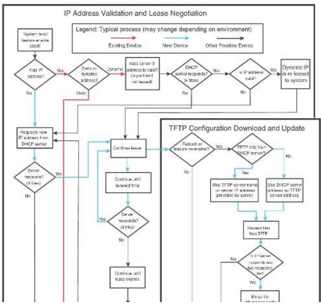
flowchart
graph TD
A["System based feature re-lease count"] --> B{Has IP address?}
B -->|Yes| C["Stable or Dynamic scheme address?"]
B -->|No| D["Requests for DHCP server"]
C --> E["Dynamic server address is valid? (in packet and release)"]
E --> F["Airs server if address is valid? (in packet and release)"]
F --> G{DHCP server responds? (4 bits)}
G -->|Yes| H["or IP address valid?"]
G -->|No| I["Dynamic IP is re-leased to system"]
H --> J{Do not reach any IP address?}
J -->|Yes| K["TFTP Configuration Download and Update"]
J -->|No| L["Continue until received time"]
L --> M{Server responds? (4 bits)}
M -->|Yes| N["Continue until lease expires"]
M -->|No| O["Continue until lease expires"]
N --> P{TDo not reach any IP address? (4 bits)}
P --> Q{Do not reach any IP address? (4 bits)}
Q -->|Yes| R["Use DHCP server address or TFTP server address"]
Q -->|No| S["Inactive line from TFTP"]
R --> T{1 IP server responds and has requested code?}
T -->|Yes| U["Magnetic line"]
T -->|No| V["End"]
style A fill:#f9f,stroke:#333
style U fill:#f9f,stroke:#333
- If the device has a dynamic address, the device asks the DHCP server to validate that address. If the server does not respond, the device will continue to use the existing address until the lease expires. If the server responds, and the IP address is outside of the DHCP address pool or has been leased to another device, it is automatically rejected, and the device receives a new IP address from the server. If the existing address is valid, the lease continues.
NOTE
The lease time interval is configured on the DHCP server, not on the client device. The ip dhcp-client lease command is set by the system, and is non-operational to a user.
- If the existing address is static, the device keeps it and the DHCP Client process is ended.
- For a leased IP address, when the lease interval reaches the renewal point, the device requests a renewal from the DHCP server:
- If the device is able to contact the DHCP server at the renewal point in the lease, the DHCP server extends the lease. This process can continue indefinitely.
- If the device is unable to reach the DHCP server after four attempts, it continues to use the existing IP address until the lease expires. When the lease expires, the dynamic IP address is removed and the device contacts the DHCP server for a new address. If the device is still unable to contact the DHCP server after four attempts, the process is ended.
The TFTP Flash image download and update step
NOTE
This process only occurs when the client device reboots, or when DHCP-client has been disabled and then re-enabled.
Once a lease is obtained from the server (described in "The IP address validation and lease negotiation step" on page 857), the device compares the filename of the requested flash image with the image stored in flash. In a stacking configuration, the device compares the filename with the image stored in the Active controller only.
- If the .bin filenames match, then the DHCP client skips the flash image download. If auto-configuration is enabled, the DHCP client proceeds with downloading the configuration files as described in "The TETR configuration download and update step".
The TFTP configuration download and update step
NOTE
This process only occurs when the client device reboots, or when Auto-Configuration has been disabled and then re-enabled.
-
When the device reboots, or the Auto-Configuration feature has been disabled and then re-enabled, the device uses information from the DHCP server to contact the TFTP server to update the running-configuration file:
-
If the DHCP server provides a TFTP server name or IP address, the device uses this information to request files from the TFTP server.
-
If the DHCP server does not provide a TFTP server name or IP address, the device requests the configuration files from the DHCP server.
-
The device requests the configuration files from the TFTP server by asking for filenames in the following order:
• bootfile name provided by the DHCP server (if configured)
- hostnameMAC-config.cfg, for example:
PowerConnect-Switch001b.ed5e.4d00-config.cfg
- hostnameMAC.cfg, for example:
PowerConnect-Switch001b.ed5e.4d00.cfg
-
PowerConnect-switch.cfg(FCX Layer 2) PowerConnect-router.cfg(FCX Layer 3)
If the device is successful in contacting the TFTP server and the server has the configuration file, the files are merged. If there is a conflict, the server file takes precedence.
If the device is unable to contact the TFTP server or if the files are not found on the server, the TFTP part of the configuration download process ends.
Configuration notes
- When using DHCP on a router, if you have a DHCP address for one interface, and you want to connect to the DHCP server from another interface, you must disable DHCP on the first interface, then enable DHCP on the second interface.
- When DHCP is disabled, and then re-enabled, or if the system is rebooted, the TFTP process requires approximately three minutes to run in the background before file images can be downloaded manually.
- Once a port is assigned a leased IP address, it is bound by the terms of the lease regardless of the link state of the port.
Disabling or re-enabling Auto-Configuration
For a switch, you can disable or enable this feature using the following commands.
PowerConnect(config)# ip dhcp-client enable PowerConnect(config)# no ip dhcp-client enable
For a router, you can disable or enable this feature using the following commands.
PowerConnect(config-if-e1000-0/1/1)# ip dhcp-client enable PowerConnect(config-if-e1000-0/1/1)# no ip dhcp-client enable
Syntax: [no] ip dhcp-client enable
Disabling or re-enabling Auto-Update
Auto-update is enabled by default. To disable it, use the following command.
PowerConnect{config}# no ip dhcp-client auto-update enabled
To re-enable auto-update after it has been disabled, use the following command.
PowerConnect(config)# ip dhcp-client auto-update enabled
Syntax: [no] ip dhcp-client auto-update enabled
The auto-update will not appear in the running-config under certain circumstances. It will appear in
PowerConnect(config)# show ip
Switch IP address: 10.44.16.116
Subnet mask: 255.255.255.0
Default router address: 10.44.16.1
TFTP server address: 10.44.16.41
Configuration filename: foundry.cfg
Image filename: None
The following example shows output from the show ip address command for a Layer 2 device.
PowerConnect{config}# show ip address
IP Address Type Lease Time Interface
10.44.16.116 Dynamic 174 0/1/1
The following example shows output from the show ip address command for a base Layer 3 device.
PowerConnect(config)# show ip address
IF Address Type Lease Time Interface
10.44.3.233 Dynamic 672651 0/1/2
1.0.0.1 Static N/A 0/1/15
The following example shows a Layer 2 device configuration as a result of the show run command.
PowerConnect(config)# show run
Current configuration:
ver 7.2.00aT7F1
module 1 FCX-24-port-management-module
1
ip address 10.44.16.116 255.255.255.0 dynamic
ip dns server-address 10.44.16.41
ip dhcp-client lease 174
in default1+=max 10 AD 1≤ 1
PowerConnect (config) ↓ show run
Current configuration:
ver 7.2.00aT7f1
1
module 1 FCX-24-port-management-module
module 2 FCX-cx4-2-port-16g-module
module 3 FCX-xfp-1-port-16g-module
vlan 1 name DEFAULT-VLAN by port
ip dns domain-name test.com
ip dns server-address 10.44.3.111
interface ethernet 0/1/2
1p address 10.44.3.233 255.255.255.0 dynamic
ip dhcp-client lease 691109
interface ethernet 0/1/15
ip address 1.0.0.1 255.0.0.0
ip helper-address 1 10.44.3.111
end
DHCP Log messages
The following DHCP notification messages are sent to the log file.
2d01h48m2ls:I: DHCP: existing ip address found, no further action needed by DHCP
2d01b48m21s:I: DHCP: Starting DHCP Client service
2d01b48m21s:I: DHCP: Stopped DHCP Client service
2d01h48m21s:T: DHCP: FCX624P Switch running-configuration changed
2d01b48m21s:1: DHCFC: sending TRTP request for bootfile name FCX-switch.cfg
2d01h48m21s:I: DHCP: TFTP unable to download running-configuration
2d01h48m21s:T: DHCP: Found static IP Address 1.1.1.1 subnet mask 255.255.255.0 pn
port 0/1/5
2d01h48m21s:T: DHCP: Client service found no DHCP server(s) on 3 possible subnet.
2d01b48m2ls:I: DHCP: changing 0/1/3 protocol from stopped to running
Configuring the management IP address and specifying the default gateway
To manage a Layer 2 Switch using Telnet or Secure Shell (SSH) CLI connections or the Web Management Interface, you must configure an IP address for the Layer 2 Switch. Optionally, you also can specify the default gateway.
Dell PowerConnect devices support both classical IP network masks (Class A, B, and C subnet masks, and so on) and Classless Interdomain Routing (CIDR) network prefix masks:
- To enter a classical network mask, enter the mask in IP address format. For example, enter "209.157.22.99 255.255.255.0" for an IP address with a Class-C subnet mask.
- To enter a prefix network mask, enter a forward slash (/) and the number of bits in the mask immediately after the IP address. For example, enter "209.157.22.99/24" for an IP address that has a network mask with 24 significant bits (ones).
By default, the CLI displays network masks in classical IP address format (example: 255.255.255.0). You can change the display to prefix format. Refer to "Changing the network mask display to prefix format" on page 869.
To assign an IP address to a Layer 2 Switch, enter a command such as the following at the global CONFIG level.
PowerConnect(config)# ip address 192.45.6.110 255.255.255.0
Syntax: ip address
or
Syntax: ip address
You also can enter the IP address and mask in CIDR format, as follows.
PowerConnect(config)# ip address 192.45.6.1/24 To specify the Layer 2 Switch default gateway, enter a command such as the following.
PowerConnect(config)# ip default-gateway 192.45.6.1 255.255.255.0
Syntax: ip default-gateway
For example, if the domain "newyork.com" is defined on a Layer 2 Switch or Layer 3 Switch and you want to initiate a ping to host "NYC01" on that domain, you need to reference only the host name in the command instead of the host name and its domain name. For example, you could enter either of the following commands to initiate the ping.
PowerConnect# ping nyc01
PowerConnect ^1 ping nyc01.newyork.com
Defining a DNS entry
You can define up to four DNS servers for each DNS entry. The first entry serves as the primary default address. If a query to the primary address fails to be resolved after three attempts, the next gateway address is queried (also up to three times). This process continues for each defined gateway address until the query is resolved. The order in which the default gateway addresses are polled is the same as the order in which you enter them.
Suppose you want to define the domain name of newyork.com on a Layer 2 Switch and then define four possible default DNS gateway addresses. To do so, enter the following commands.
PowerConnect(config)# ip dns domain-name newyork.com
PowerConnect(config)# ip dns server-address 209.157.22.199 205.96.7.15
208.95.7.25 201.98.7.15
Syntax: ip dns server-address
In this example, the first IP address in the ip dns server-address... command becomes the primary gateway address and all others are secondary addresses. Because IP address 201.98.7.15 is the last address listed, it is also the last address consulted to resolve a query.
Using a DNS name To initiate a trace route
Suppose you want to trace the route from a Layer 2 Switch to a remote server identified as NYC02 on domain newyork.com. Because the newyork.com domain is already defined on the Layer 2 Switch, you need to enter only the host name, NYC02, as noted in the following command.
PowerConnect# traceroute nyc02
Syntax: traceroute
NOTE
In the previous example, 209.157.22.199 is the IP address of the domain name server (default DNS gateway address), and 209.157.22.80 represents the IP address of the NYC02 host.
FIGURE 134 Querying a Host on the newyork.com Domain
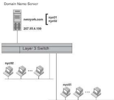
flowchart
graph TD
A["Domain Name Server"] --> B["newyork.com"]
B --> C["207.05.6.199"]
C --> D["Layer 3 Switch"]
D --> E["nyc02"]
D --> F["..."]
D --> G["nyc01"]
E --> H["nyc01"]
F --> I["..."]
G --> J["..."]
Changing the TTL threshold
The TTL threshold prevents routing loops by specifying the maximum number of router hops an IP packet originated by the Layer 2 Switch can travel through. Each device capable of forwarding IP that receives the packet decrements (decreases) the packet TTL by one. If a router receives a packet with a TTL of 1 and reduces the TTL to zero, the router drops the packet.
The default TTL is 64. You can change the TTL to a value from 1 through 255.
To modify the TTL threshold to 25, enter the following commands.
By allowing multiple subnet DHCP requests to be sent on the same wire, you can reduce the number of router ports required to support secondary addressing as well as reduce the number of DHCP servers required, by allowing a server to manage multiple subnet address assignments.
FIGURE 135 DHCP requests in a network without DHCP Assist on the Layer 2 Switch
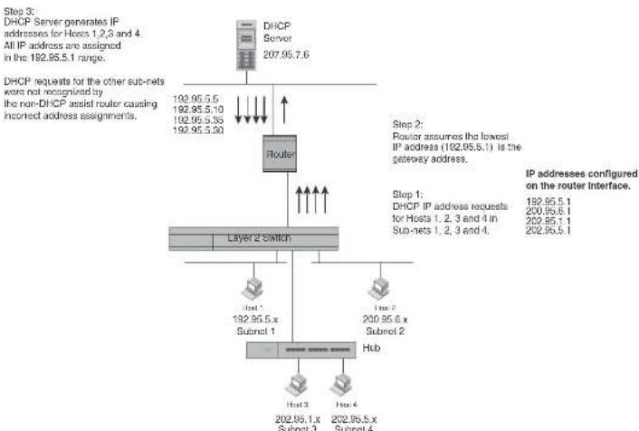
flowchart
graph TD
A["DHCP Server 207.95.7.6"] --> B["Router"]
B --> C["Layer 2 Switch"]
C --> D["Host 1 192.95.5 x Subnet 1"]
C --> E["Host 2 200.95.6 x Subnet 2"]
C --> F["Hub"]
G["DHCP requests for the other sub-nets were not recognised by the non-DHCP assist router causing infrared address assignments."] --> B
H["Step 3: DHCP Server generates IP addresses for Hosts 1, 2, 3 and 4. All IP address are assigned in the 192.95.5.1 range."] --> B
I["Step 2: Router assumes the lowest IP address (192.95.5.1) is the gateway address."] --> B
J["Step 1: DHCP IP address requests for Hosts 1, 2, 3 and 4 in Sub-nets 1, 2, 3 and 4."] --> B
K["IP addresses configured on the router interface."] --> L["Host 3 202.95.1.x Subnet 3"]
K --> M["Host 4 202.95.5.x Subnet 4"]
In a network operating without DHCP Assist, hosts can be assigned IP addresses from the wrong subnet range because a router with multiple subnets configured on an interface cannot distinguish among DHCP discovery packets received from different subnets.
How DHCP Assist works
Upon initiation of a DHCP session, the client sends out a DHCP discovery packet for an address from the DHCP server as seen in Figure 136. When the DHCP discovery packet is received at a Layer 2 Switch with the DHCP Assist feature enabled, the gateway address configured on the receiving interface is inserted into the packet. This address insertion is also referred to as stamping.
FIGURE 136 DHCP requests in a network with DHCP Assist operating on a PowerConnect Switch

flowchart
graph TD
A["DHCP Server 207.95.7.6"] --> B["Router"]
B --> C["Layer 2 Switch"]
C --> D["Interface 2"]
D --> E["Host 1 192.95.5.x Subnet 1"]
C --> F["Interface 3: Router forwards the DHCP request to the server without touching the gateway address inserted in the packet by the switch."]
C --> G["Interface 4: Switch stamps each DHCP request with the gateway address of the corresponding subnet of the receiving port."]
C --> H["Interface 5: 200.95.6.x Subnet 2 Hub"]
C --> I["Interface 6: 202.95.5.1 Gateway addresses: 192.95.5.1, 200.95.6.1, 202.95.1.1, 202.95.5.1"]
C --> J["Interface 7: DHCP IP address requests for Hosts 1, 2, 3 and 4 in Subnets 1, 2, 3 and 4."]
NOTE
The DHCP relay function of the connecting router must be turned on.
FIGURE 137 DHCP offers are forwarded back toward the requestors

flowchart
graph TD
A["DHCP Server 207.95.7.6"] --> B["Router"]
B --> C["Layer 2 Switch"]
C --> D["Host 1 192.95.5.10"]
C --> E["Host 2 200.95.6.15"]
C --> F["Host 3 202.95.1.35"]
C --> G["Host 4 202.95.5.25"]
H["DHCP response with IP addresses for Subnets 1, 2, 3 and 4"] --> B
I["Step 5: IP addresses are distributed to the appropriate hosts."] --> C
Up to eight addresses can be defined for each gateway list in support of ports that are multi-homed. When multiple IP addresses are configured for a gateway list, the Layer 2 Switch inserts the addresses into the discovery packet in a round robin fashion.
Up to 32 gateway lists can be defined for each Layer 2 Switch.
Example
To create the configuration indicated in Figure 136 and Figure 137, enter commands such as the following.
PowerConnect(config)# dhcp-gateway-list 1 192.95.5.1
PowerConnect(config)# dhcp-gateway-list 2 200.95.6.1
PowerConnect(config)# dhcp-gateway-list 3 202.95.1.1 202.95.3.1
PowerConnect(config)# interface ethernet 2
PowerConnect(config-if-e1000-2)# dhcp-gateway-list 1
PowerConnect(config-if-e1000-2)# interface ethernet 8
PowerConnect(config-if-e1000-8)# dhcp-gateway-list 3
PowerConnect(config-if-e1000-8)# interface ethernet 14
PowerConnect(config-if-e1000-14)# dhcp-gateway-list 2
Syntax: dhcp-gateway-list
Displaying IP configuration information and statistics
The following sections describe IP display options for Layer 3 Switches and Layer 2 Switches:
- To display IP information on a Layer 3 Switch, refer to "Displaying IP information – Layer 3 Switches" on page 869.
- To display IP information on a Layer 2 Switch, refer to "Displaying IP information – Layer 2 Switches" on page 883.
Changing the network mask display to prefix format
By default, the CLI displays network masks in classical IP address format (example: 255.255.255.0). You can change the displays to prefix format (example: /18) on a Layer 3 Switch
- IP interfaces – refer to "Displaying IP interface information" on page 873.
- ARP entries – refer to "Displaying ARP entries" on page 874.
• Static ARP entries – refer to "Displaying ARP entries" on page 874. - IP forwarding cache – refer to "Displaying the forwarding cache" on page 877.
- IP route table - refer to "Displaying the IP route table" on page 878.
- IP traffic statistics – refer to "Displaying IP traffic statistics" on page 881.
The following sections describe how to display this information.
In addition to the information described below, you can display the following IP information. This information is described in other parts of this guide:
• RIP
- OSPF
• BGP4
• DVMRP
• PIM
- VRRP or VRRPE
Displaying global IP configuration information
To display IP configuration information, enter the following command at any CLI level.
PowerConnect# show ip
Global Settings
tt1: 64, arp-age: 10, bootp-relay-max-hops: 4
router-id : 207.95.11.128
enabled : UDP-Broadcast-Forwarding TRDP Proxy-ARP RARP OSPF
disabled: BGP4 Load-Sharing RIF DVMRP FSRP VRRF
Static Routes
Index IP Address Subnet Mask Next Hop Router Metric Distance
1 0.0.0.0 0.0.0.0 209.157.23.2 1 1
Policies
TABLE 159 CLI display of global IP configuration information - Layer 3 Switch
| This field... Displays... | |
| Global settings | |
| ttl The Time-To-Live (TTL) for IP packets. The TTL specifies the maximum number of router hops a packet can travel before reaching the router. If the packet TTL value is higher than the value specified in this field, the router drops the packet.To change the maximum TTL, refer to “Changing the TTL threshold” on page 815. | |
| arp-age The ARP aging period. This parameter specifies how many minutes an inactive ARP entry remains in the ARP cache before the router ages out the entry.To change the ARP aging period, refer to “Changing the ARP aging period” on page 812. | |
| bootp-relay-max-hops | The maximum number of hops away a BootP server can be located from the router and still be used by the router clients for network booting.To change this value, refer to “Changing the maximum number of hops to a BootP relay server” on page 840. |
| router-id The 32-bit number that uniquely identifies the router.By default, the router ID is the numerically lowest IP interface configured on the router. To change the router ID, refer to “Changing the router ID” on page 809. | |
| enabled The IP-related protocols that are enabled on the router. | |
| disabled The IP-related protocols that are disabled on the router. | |
| Static routes | |
| Index The row number of this entry in the IP route table. | |
| IP Address The IP address of the route destination. | |
| Subnet Mask The network mask for the IP address. | |
| Next Hop Router | The IP address of the router Interface to which the router sends packets for the route. |
| Metric | The cost of the route. Usually, the metric represents the number of hops to the destination. |
| Distance | The administrative distance of the route. The default administrative distance for static IP routes in routers is 1.To list the default administrative distances for all types of routes or to change the administrative distance of a static route, refer to “Changing administrative distances” on |
| Port | The Layer 4 TCP or UDP port the policy checks for in packets. The port can be displayed by its number or, for port types the router recognizes, by the well-known name. For example, TCP port 80 can be displayed as HTTP.NOTE: This field applies only if the IP protocol is TCP or UDP. |
| Operator | The comparison operator for TCP or UDP port names or numbers.NOTE: This field applies only if the IP protocol is TCP or UDP. |
Displaying CPU utilization statistics
You can display CPU utilization statistics for IP protocols using the show process cpu command.
The show process cpu command includes CPU utilization statistics for ACL, 802.1x, and L2VLAN. L2VLAN contains any packet transmitted to a VLAN by the CPU, including unknown unicast, multicast, broadcast, and CPU forwarded Layer 2 traffic.
To display CPU utilization statistics for the previous one-second, one-minute, five-minute, and fifteen-minute intervals, enter the following command at any level of the CLI.
PowerConnect# show process cpu
| Process Name | 5Sec(%) | 1Min(%) | 5Min(%) | 15Min(%) | Runtime (ms) |
| ACL | 0.00 | 0.00 | 0.00 | 0.00 | 0 |
| ARP | 0.01 | 0.01 | 0.01 | 0.01 | 714 |
| BGP | 0.00 | 0.00 | 0.00 | 0.00 | 0 |
| DOTIX | 0.00 | 0.00 | 0.00 | 0.00 | 0 |
| GVRF | 0.00 | 0.00 | 0.00 | 0.00 | 0 |
| ICMP | 0.00 | 0.00 | 0.00 | 0.00 | 161 |
| IP | 0.00 | 0.00 | 0.00 | 0.00 | 229 |
| LZVLAN | 0.01 | 0.00 | 0.00 | 0.01 | 673 |
| OSPF | 0.00 | 0.00 | 0.00 | 0.00 | 0 |
| RIP | 0.00 | 0.00 | 0.00 | 0.00 | 9 |
| STP | 0.00 | 0.00 | 0.00 | 0.00 | 7 |
| VRRF | 0.00 | 0.00 | 0.00 | 0.00 | 0 |
To display utilization statistics for a specific number of seconds, enter a command such as the following.
| PowerConnect# show process cpu 2 | ||
| Statistics for last 1 sec and 80 ms | ||
| Process Name | Sec(%) | Time(ms) |
| ACL | 0 | 0.00 |
| ARP | 1 | 0.01 |
| BGP | 0 | 0.00 |
| DGT1X | 0 | 0.00 |
| GVRP | 0 | 0.00 |
| TCMP | 0 | 0.00 |
| IP | 0 | 0.00 |
| L2VLAN | 1 | 0.01 |
| OSPF | 0 | 0.00 |
| RIP | 0 | 0.00 |
| STP | 0 | 0.00 |
| VRRP | 0 | 0.00 |
When you specify how many seconds' worth of statistics you want to display, the software selects the sample that most closely matches the number of seconds you specified. In this example, statistics are requested for the previous two seconds. The closest sample available is actually for the previous 1 second plus 80 milliseconds.
Syntax: show process cpu [
The
Displaying IP interface information
To display IP interface information, enter the following command at any CLI level.
PowerConnect ^1 show ip interface
TABLE 160 CLI display of interface IP configuration information (Continued)
| This field... Displays... | |
| Method Whether the IP address has been saved in NVRAM. If you have set the IP address for the interface in the CLI or Web Management Interface, but have not saved the configuration, the entry for the interface in the Method field is "manual". | |
| Status | The link status of the interface. If you have disabled the interface with the disable command, the entry in the Status field will be "administratively down". Otherwise, the entry in the Status field will be either "up" or "down". |
| Protocol Whether the interface can provide two-way communication. If the IP address is configured, and the link status of the interface is up, the entry in the protocol field will be "up". Otherwise the entry in the protocol field will be "down". | |
To display detailed IP information for a specific interface, enter a command such as the following.
| PowerConnect# show ip interface ethernet 1/1 | |
| Interface Ethernet 1/1 | |
| port state: UP | |
| ip address: 192.168.9.51 subnet mask: 255.255.255.0 | |
| encapsulation: ETHERNET, mtu: 1500, metric: 1 | |
| directed-broadcast-forwarding: disabled | |
| proxy arp: disabled | |
| ip arp-sqe: 10 minutes | |
| Ip Flow switching is disabled | |
| No Helper Addresses are configured. | |
| No inbound ip access-list is set | |
| No outgoing ip access-list is set |
Displaying ARP entries
You can display the ARP cache and the static ARP table. The ARP cache contains entries for devices attached to the Layer 3 Switch. The static ARP table contains the user-configured ARP entries. An entry in the static ARP table enters the ARP cache when the entry interface comes up.
The tables require separate display commands or Web management options.
The mac-address
The
The
NOTE
The
The
NOTE
The entry numbers in the ARP cache are not related to the entry numbers for static ARP table entries.
This display shows the following information. The number in the left column of the CLI display is the row number of the entry in the ARP cache. This number is not related to the number you assign to static MAC entries in the static ARP table.
TABLE 161 CLI display of ARP cache
This field... Displays...
| Total number of ARP Entries | The number of entries in the ARP cache. |
| Maximum capacity | The total number of ARP entries supported on the device. |
| IP Address The IP address of the device. | |
| MAC Address The MAC address of the device. | |
| This field... Displays... | |
| Port The port on which the entry was learned.NOTE: If the ARP entry type is DHCP, the port number will not be available until the entry gets resolved through ARP. | |
| Status The status of the entry, which can be one of the following:Valid – This a valid ARP entry.Pend – The ARP entry is not yet resolved. | |
Displaying the static ARP table
To display the static ARP table instead of the ARP cache, enter the following command at any CLI level.
| PowerConnect show ip static-arp | |||
| Static ARP table size: 512, configurable from 512 to 1024 | |||
| Index | IP Address | MAC Address | Port |
| 1 | 207.95.6.111 | 0800.093b.d210 | 1/1 |
| 3 | 207.95.6.123 | 0800.093b.d211 | 1/1 |
This example shows two static entries. Note that because you specify an entry index number when you create the entry, it is possible for the range of index numbers to have gaps, as shown in this example.
NOTE
The entry number you assign to a static ARP entry is not related to the entry numbers in the ARP cache.
Syntax: show ip static-arp [ethernet [
The
The
TABLE 162 CLI display of static ARP table
| This field... Displays... |
| Static ARP table size The maximum number of static entries that can be configured on the device using the current memory allocation. The range of valid memory allocations for static ARP entries is listed after the current allocation. To change the memory allocation for static ARP entries, refer to "Changing the maximum number of entries the static ARP table can hold" on page 814. |
| Index The number of this entry in the table. You specify the entry number when you create the entry. |
| IP Address The IP address of the device. |
| MAC Address The MAC address of the device. |
| Port The port attached to the device the entry is for. |
Displaying the forwarding cache
To display the IP forwarding cache, enter the following command at any CLI level.
PowerConnect ^1 show ip cache
Total number of cache entries: 3
D:Dynamic F:Permanent F:Forward U:Us C:Complex Filter
| W:Wait ARP I:ICMP Deny K:Drop R:Fragment S:Snap Encap | |||||||
| TP Address | Next Hop | MAC | Type | Port | Vlan | Pri | |
| 1 | 192.168.1.11 | DIRECT | 0000.0000.0000 | PU | n/a | C | |
| 2 | 192.168.1.255 | DIRECT | 0000.0000.0000 | PU | n/a | C | |
| 3 | 255.255.255.255 | DIRECT | 0000.0000.0000 | PU | n/a | C | |
Syntax: show ip cache [
The
The
For example, to begin displaying the cache at row 10, enter the following command.
show in cache 0
TABLE 163 CLI display of IP forwarding cache - Layer 3 Switch (Continued)
| This field... Displays... | |
| Type The type of host entry, which can be one or more of the following: | |
| D - DynamicP - PermanentF - ForwardU - UsC - Complex FilterW - Wait ARPI - ICMP DenyK - DropR - FragmentS - Snap Encap | |
| Port | The port through which this device reaches the destination. For destinations that are located on this device, the port number is shown as "n/a". |
| VLAN Indicates the VLANs the listed port is in. | |
| Pri The QoS priority of the port or VLAN. | |
Displaying the IP route table
To display the IP route table, enter the following command at any CLI level.
PowerConnect# show ip route
Total number of IP routes: 514
| Start Index: 1 | B: BGP D: Connected | R: RIP S: Static | O: CSPF Y: Candidate default | ||
| Destination | NetMask | Gateway | Port | Cost | Type |
| 1.1.0.0 | 255.255.0.0 | 99.1.1.2 | 1/1 | 2 | R |
| 1.2.0.0 | 255.255.0.0 | 98.1.1.2 | 1/1 | 2 | R |
| 1.3.0.0 | 255.255.0.0 | 99.1.1.2 | 1/1 | 2 | R |
| 1.4.0.0 | 255.255.0.0 | 98.1.1.2 | 1/1 | 2 | R |
| 1.5.0.0 | 255.255.0.0 | 99.1.1.2 | 1/1 | 2 | R |
| 1.6.0.0 | 255.255.0.0 | 99.1.1.2 | 1/1 | 2 | R |
| 1.7.0.0 | 255.255.0.0 | 98.1.1.2 | 1/1 | 2 | R |
| 1.8.0.0 | 255.255.0.0 | 99.1.1.2 | 1/1 | 2 | R |
The bgp option displays the BGP4 routes.
The direct option displays only the IP routes that are directly attached to the Layer 3 Switch.
The ospf option displays the OSPF routes.
The rip option displays the RIP routes.
The static option displays only the static IP routes.
The default routes are displayed first.
Here is an example of how to use the direct option. To display only the IP routes that go to devices directly attached to the Layer 3 Switch, enter the following command.
PowerConnect# show ip route direct
| Start index: 1 B:BGP D:Connected R:RTP S:Static O:CSPF *:Candidate default | ||||||
| Destination | NetMask | Gateway | Fort | Cost | Type | |
| 209.157.22.0 | 255.255.255.0 | 0.0.0.0 | 4/11 | 1 | D | |
Notice that the route displayed in this example has "D" in the Type field, indicating the route is to a directly connected device.
Here is an example of how to use the static option. To display only the static IP routes, enter the following command.
PowerConnect ^1 show ip route static
| Start index: 1 B:BG2 D:Connected R:RIP S:Static O:OSPF *:Candidate default | |||||
| Destination | NetMask | Gateway | Port | Cost | Type |
| 192.144.33.11 | 255.255.255.0 | 209.157.22.12 | 1/1 | 2 | S |
Notice that the route displayed in this example has "S" in the Type field, indicating the route is static.
Here is an example of how to use the longer option. To display only the routes for a specified IP address and mask, enter a command such as the following.
PowerConnect# show ip route 209.159.0.0/16 longer
Starting index: 1 B:RGP D:Directly-Connected R:RIP S:Static D:OSPF
Example
PowerConnect# show ip route summary
IP Routing Table - 35 entries:
6 connected, 28 static, 0 RIP, 1 CSPF, 0 BGP, 0 ISIS, 0 MPLS
Number of prefixes:
/0: 1 /16: 27 /22: 1 /24: 5 /32: 1
Syntax: show ip route summary
In this example, the IP route table contains 35 entries. Of these entries, 6 are directly connected devices, 28 are static routes, and 1 route was calculated through OSPF. One of the routes has a zero-bit mask (this is the default route), 27 have a 22-bit mask, 5 have a 24-bit mask, and 1 has a 32-bit mask.
The following table lists the information displayed by the show ip route command.
TABLE 164 CLI display of IP route table
| This field... Displays... |
| Destination The destination network of the route. |
| NetMask The network mask of the destination address. |
| Gateway The next-hop router.An asterisk (*) next to the next-hop router indicates that it is one of multiple Equal-Cost Multi-Path (ECMP) next hops for a given route. The asterisk will initially appear next to the first next hop for each route with multiple ECMP next hops. If the ARP entry for the next hop* agos out or is cleared, then the next packet to be routed through the PowerConnect device whose destination matches that route can cause the asterisk to move to the next hop down the list of ECMP next hops for that route. This means that if the next hop* goes down, the asterisk can move to another next hop with equal cost. |
Port The port through which this router sends packets to reach the route's destination.
Cost The route's cost.
Type The route type, which can be one of the following:
• B - The route was learned from BGP.
- D - The destination is directly connected to this Laver 3 Switch.
To clear route 209.157.22.0/24 from the IP routing table, enter the following command.
PowerConnect# clear ip route 209.157.22.0/24
Syntax: clear ip route [
or
Syntax: clear ip route [
Displaying IP traffic statistics
To display IP traffic statistics, enter the following command at any CLI level.
PowerConnect# show ip traffic
IP Statistics
139 received, 145 sent, 0 forwarded
0 filtered, 0 fragmented, 0 reassembled, 0 bad header
0 no route, 0 unknown proto, 0 no buffer, 0 other errors
ICMP Statistics
Received:
0 total, 0 errors, 0 unreachable, 0 time exceed
0 parameter, 0 source quench, 0 redirect, 0 echo,
0 echo reply, 0 timestamp, 0 timestamp reply, 0 addr mask
0 addr mask reply, 0 irdp advertisement, 0 irdp solicitation
0 total, 0 errors, 0 unreachable, 0 time exceed
0 parameter, 0 source quench, 0 redirect, 0 echo,
0 echo reply, 0 timestamp, 0 timestamp reply, 0 addr mask
0 addr mask reply, 0 irdp advertisement, 0 irdp solicitation
UDP Statistics
1 received, 0 sent, 1 no port, 0 input errors
TCP Statistics
0 active opens, 0 passive opens, 0 failed attempts
0 active resets, 0 passive resets, 0 input errors
138 in segments, 141 out segments, 4 retransmission
TABLE 165 CLI display of IP traffic statistics - Layer 3 Switch (Continued)
| This field... | Displays... |
| fragmented The total number of IP packets fragmented by this device to accommodate the MTU of this device or of another device. | |
| reassembled The total number of fragmented IP packets that this device re-assembled. | |
| bad header The number of IP packets dropped by the device due to a bad packet header. | |
| no route The number of packets dropped by the device because there was no route. | |
| unknown proto The number of packets dropped by the device because the value in the Protocol field of the packet header is unrecognized by this device. | |
| no buffer This information is used by Dell customer support. | |
| other errors The number of packets dropped due to error types other than those listed above. | |
| ICMP statistics | |
| The ICMP statistics are derived from RFC 792, "Internet Control Message Protocol", RFC 950, "Internet Standard Submitting Procedure", and RFC 1256, "ICMP Router Discovery Messages". Statistics are organized into Sent and Received. The field descriptions below apply to each. | |
| total The total number of ICMP messages sent or received by the device. | |
| errors This information is used by Dell customer support. | |
| unreachable The number of Destination Unreachable messages sent or received by the device. | |
| time exceed The number of Time Excoded messages sent or received by the device. | |
| parameter The number of Parameter Problem messages sent or received by the device. | |
| source quench | The number of Source Quench messages sent or received by the device. |
| redirect | The number of Redirect messages sent or received by the device. |
| echo | The number of Echo messages sent or received by the device. |
| echo reply | The number of Echo Reply messages sent or received by the device. |
| timestamp | The number of Timestamp messages sent or received by the device. |
| timestamp reply | The number of Timestamp Reply messages sent or received by the device. |
| passive opens The number of TCP connections opened by this device in response to connection requests (TCP SYNs) received from other devices. | |
| failed attempts This information is used by Dell customer support. | |
| active resets The number of TCP connections this device reset by sending a TCP RESET message to the device at the other end of the connection. | |
| passive resets The number of TCP connections this device reset because the device at the other end of the connection sent a TCP RESET message. | |
| input errors This information is used by Dell customer support. | |
| In segments The number of TCP segments received by the device. | |
| out segments The number of TCP segments sent by the device. | |
| retransmission The number of segments that this device retransmitted because the retransmission timer for the segment had expired before the device at the other end of the connection had acknowledged receipt of the segment. | |
| RIP statisticsThe RIP statistics are derived from RFC 1058, “Routing Information Protocol”. | |
| requests sent The number of requests this device has sent to another RIP router for all or part of its RIP routing table. | |
| requests received The number of requests this device has received from another RIP router for all or part of this device RIP routing table. | |
| responses sent The number of responses this device has sent to another RIP router request for all or part of this device RIP routing table. | |
| responses received The number of responses this device has received to requests for all or part of another RIP router routing table. | |
| unrecognized This information is used by Dell customer support. | |
| bad version The number of RIP packets dropped by the device because the RIP version was either invalid or is not supported by this device. | |
bad addr family The number of RIP packets dropped because the value in the Address Family Identifier field of
- Global IP settings – refer to "Displaying global IP configuration information" on page 884.
- ARP entries – refer to "Displaying ARP entries" on page 884.
- IP traffic statistics – refer to "Displaying IP traffic statistics" on page 885.
Displaying global IP configuration information
To display the Layer 2 Switch IP address and default gateway, enter the following command.
PowerConnect# show ip
Switch IP address: 192.168.1.2
Subnet mask: 255,255,255.0
Default router address: 192.168.1.1
TFTP server address: None
Configuration filename: None Image filename: None
Syntax: show ip
This display shows the following information.
TABLE 166 CLI display of global IP configuration information - Layer 2 Switch
| This field... Displays... | |
| IP configuration | |
| Switch IP address The management IP address configured on the Layer 2 Switch. Specify this address for Telnet or Web management access. | |
| Subnet mask The subnet mask for the management IP address. | |
| Default router address The address of the default gateway, if you specified one. | |
| Most recent TFTP access | |
| TFTP server address | The IP address of the most-recently contacted TFTP server, if the switch has contacted a TFTP server since the last time the software was reloaded or the |
Syntax: show arp
This display shows the following information.
TABLE 167 CLI display of ARP cache
| This field... Displays... | |
| Total ARP Entries The number of entries in the ARP cache. | |
| Maximum capacity | The total number of ARP entries supported on the device. |
| IP The IP address of the device. | |
| Mac The MAC address of the device.NOTE: If the MAC address is all zeros, the entry is for the default gateway, but the Layer 2 Switch does not have a link to the gateway. | |
| Port The port on which the entry was learned. | |
| Ago The number of minutes the entry has remained unused. If this value reaches the ARP aging period, the entry is removed from the cache. | |
| Vianld The VLAN the port that learned the entry is in.NOTE: If the MAC address is all zeros, this field shows a random VLAN ID, since the Layer 2 Switch does not yet know which port the device for this entry is attached to. | |
Displaying IP traffic statistics
To display IP traffic statistics on a Layer 2 Switch, enter the following command at any CLI level.
PowerConnect# show ip traffic
IP Statistics
27 received, 24 sent
0 fragmented, 0 reassembled, 0 bad header
0 no route, 0 unknown proto, 0 no buffer, 0 other errors
ICMP Statistics
Received:
The show ip traffic command displays the following information.
TABLE 168 CLI display of IP traffic statistics – Layer 2 Switch
| This field... Displays... |
| IP statistics |
| received The total number of IP packets received by the device. |
| sent The total number of IP packets originated and sent by the device. |
| fragmented The total number of IP packets fragmented by this device to accommodate the MTU of this device or of another device. |
| reassembled The total number of fragmented IP packets that this device re-assembled. |
| bad header The number of IP packets dropped by the device due to a bad packet header. |
| no route The number of packets dropped by the device because there was no route. |
| unknown proto The number of packets dropped by the device because the value in the Protocol field of the packet header is unrecognized by this device. |
| no buffer This information is used by Dell customer support. |
| other errors The number of packets that this device dropped due to error types other than the types listed above. |
ICMP statistics
| The ICMP statistics are derived from RFC 792, "Internet Control Message Protocol", RFC 950, "Internet Standard Subnotting Procedure", and RFC 1256, "ICMP Router Discovery Messages". Statistics are organized into Sent and Received. The field descriptions below apply to each. |
total The total number of ICMP messages sent or received by the device.
| errors This information is used by Dell customer support. | |
| unreachable The number of Destination Unreachable messages sent or received by the device. | |
| time exceed | The number of Time Exceeded messages sent or received by the device. |
| parameter | The number of Parameter Problem messages sent or received by the device. |
| source quench | The number of Source Quench messages sent or received by the device. |
| This field... | Displays... |
| no port | The number of UDP packets dropped because the packet did not contain a valid UDP port number. |
| Input errors This information is used by Dell customer support. | |
| TCP statisticsThe TCP statistics are derived from RFC 793, "Transmission Control Protocol". | |
| current active tcbs The number of TCP Control Blocks (TCBs) that are currently active. | |
| tcbs allocated The number of TCBs that have been allocated. | |
| tcbs froed The number of TCBs that have been froed. | |
| tcbs protected This information is used by Dell customer support. | |
| active opens The number of TCP connections opened by this device by sending a TCP SYN to another device. | |
| passive opens The number of TCP connections opened by this device in response to connection requests (TCP SYNs) received from other devices. | |
| failed attempts This information is used by Dell customer support. | |
| active resets The number of TCP connections this device reset by sending a TCP RESET message to the device at the other end of the connection. | |
| passive resets The number of TCP connections this device reset because the device at the other end of the connection sent a TCP RESET message. | |
| input errors This information is used by Dell customer support. | |
| in segments The number of TCP segments received by the device. | |
| out segments The number of TCP segments sent by the device. | |
| retransmission The number of segments that this device retransmitted because the retransmission timer for the segment had expired before the device at the other end of the connection had acknowledged receipt of the segment. | |
Chapter
Configuring Multicast Listening Discovery (MLD) Snooping 27 on PowerConnect B-Series FCX Switches
Table 169 lists the individual Dell PowerConnect switches and the MLD snooping features they support..
TABLE 169 Supported MLD snooping features
| Feature PowerConnect B-Series FCX | |
| MLD V1/V2 snooping (global and local) | Yes |
| MLD fast leave for V1 Yes | |
| MLD tracking and fast leave for V2 Yes | |
| Static MLD and IGMP groups with support for proxy | Yes |
Overview
The default method a PowerConnect uses to process an IPv6 multicast packet is to broadcast it to all ports except the incoming port of a VLAN. Packets are flooded by hardware without going to CPU, which may result in some clients receiving unwanted traffic.
MLD Snooping provides multicast containment by forwarding traffic only to those clients that have MLD receivers for a specific multicast group (destination address). The PowerConnect maintains the MLD group membership information by processing MLD reports and generating messages so traffic can be forwarded to ports receiving MLD reports. This is analogous to IGMP Snooping on the Layer3 switches.
An IPv6 multicast address is a destination address in the range of FF00::/8. A limited number of
The interfaces respond to general queries by sending a membership report containing one or more of the following records associated with a specific group:
- Current-state record - Indicates the sources from which the interface wants to receive or not receive traffic. This record contains the source addresses of the interfaces and whether or not traffic will be included (IS_IN) or excluded (IS_EX) from that source address.
- Filter-mode-change record - If the interface changes its current state from IS_IN to IS_EX, a TO_EX record is included in the membership report. Likewise, if an interface current state changes from IS_EX to IS_IN, a TO_IN record appears in the membership report.
- MLDv1 leave report - Equivalent to a TO_IN (empty) record in MLDv2. This record means that no traffic from this group will be received regardless of the source.
- An MLDv1 group report - Equivalent to an IS_EX (empty) record in MLDv2. This record means that all traffic from this group will be received regardless of source.
- Source-list-change record - If the interface wants to add or remove traffic sources from its membership report, the report can include an ALLOW record, which contains a list of new sources from which the interface wishes to receive traffic. The report can also contain a BLOCK record, which lists current traffic sources from which the interface wants to stop receiving traffic.
MLD protocols provide a way for clients and a device to exchange messages, and allow the device to build a database indicating which port wants what traffic. Since the MLD protocols do not specify forwarding methods, MLD Snooping or multicast protocols such as IPv6 PIM-Sparse Mode (PIM SM) are required to handle packet forwarding. PIM SM can route multicast packets within and outside a VLAN, while MLD Snooping can switch packets only within a VLAN. These devices do not support PIM-SM routing.
If a VLAN is not MLD Snooping-enabled, it floods IPv6 multicast data and control packets to the entire VLAN in hardware. When snooping is enabled, MLD packets are trapped to the CPU. Data packets are mirrored to the CPU and VLAN flooded. The CPU then installs hardware resources so subsequent data packets can be hardware-switched to desired ports without going through the CPU. If there is no client report, the hardware resource drops the data stream. The hardware can either match group addresses only (* G), or both source and group (S G) addresses in the data stream. If MLDv2 is configured in any port of a VLAN, the VLAN uses an (S G) match, otherwise it uses (* G). Because the hardware can match only the lowest 32 bits of a 128 bit IPv6 address, the output interfaces (OIF) of a hardware resource are the superset of the OIF of all data streams.
NOTE
For this command to take effect, you must save the configuration and reload the switch.
The hardware resource limit applies only to snooping-enabled VLANs. In VLANs where snooping is not enabled, multicast streams are switched in hardware without using any pre-installed resources.
The Dell PowerConnect device supports up to 32K of MLD groups. They are produced by client membership reports.
Configuration notes
- Servers (traffic sources) are not required to send MLD memberships.
• The default MLD version is V1. - Hardware resources are installed only when there is data traffic. If a VLAN is configured for MLDv2, the hardware matches (S G), otherwise it matches (* G).
- You can configure the maximum number of groups and hardware-switched data streams.
- The device supports static groups applying to the entire VLAN, or to specific ports. The device acts as a proxy to send MLD reports for the static groups when receiving queries.
- A user can configure static router ports, forcing all multicast traffic to be sent to these ports.
- All devices support fast leave for MLDv1, which stops traffic immediately to any port that has received a leave message.
- All devices support tracking and fast leave for MLDv2, which tracks all MLDv2 clients. If the only client on a port leaves, traffic is stopped immediately.
- An MLD device can be configured as a querier (active) or non-querier (passive). Queriers send queries. Non-queriers listen for queries and forward them to the entire VLAN.
- Every VLAN can be independently configured as a querier or a non-querier.
- A VLAN that has a connection to an IPv6 PIM-enabled port on another router should be configured as a non-querier. When multiple snooping devices connect together and there is no connection to IPv6 PIM ports, only one device should be configured as the querier. If multiple devices are configured as active, only one will continue to send queries after the devices have exchanged queries. Refer to "Configuring queriers and non-queriers" on page 892
When any port of a VLAN is configured for MLDv2, the VLAN matches both source and group (S G) in hardware switching. If no port is configured for MLDv2, the VLAN matches group only (* G). Matching (S G) requires more hardware resources than (* G) when there are multiple servers sharing the same group. For example, two data streams from different sources to the same group require two (S G) entries in MLDv2, compared to only one (* G) in MLDv1. Dell recommends that you use MLDv2 only in a source-specific application. Because each VLAN can be configured for the version independently, some VLANs might match (* G) while others match (S G).
To receive data traffic, MLD Snooping requires clients to send membership reports. If a client does not send reports, you must configure a static group to force traffic to client ports. The static group can either apply to some ports or to the entire VLAN.
Configuring queriers and non-queriers
An MLD Snooping-enabled device can be configured as a querier (active) or non-querier (passive). An MLD querier sends queries; a non-querier listens for MLD queries and forwards them to the entire VLAN. VLANs can be independently configured as queriers or non-queriers. If a VLAN has a connection to an IPv6 PIM-enabled port on another router, the VLAN should be configured as a non-querier. When multiple MLD snooping devices are connected together, and there is no connection to an IPv6 PIM-enabled port, one of the devices should be configured as a querier. If multiple devices are configured as queriers, after multiple devices exchange queries, then all devices except the winner (the device with the lowest address) stop sending queries. Although the system works when multiple devices are configured as queriers, Dell recommends that only one device, preferably the one with the traffic source, is configured as the querier.
Because non-queriers always forward multicast data traffic and MLD messages to router ports which receive MLD queries or IPv6 PIM hellos, Dell recommends that you configure the devices with the data traffic source (server) as queriers. If a server is attached to a non-querier, the non-querier always forwards traffic to the querier regardless of whether or not there are clients on the querier.
NOTE
In a topology with one or more connected devices, at least one device must be running PIM, or configured as active. Otherwise, no devices can send queries, and traffic cannot be forwarded to clients.
NOTE
To avoid version deadlock, when an interface receives a report with a lower version than that for which it has been configured, the interface does not automatically downgrade the running MLD version.
Configuring MLD snooping
Configuring MLD Snooping on Stackable devices consists of the following global and VLAN-specific tasks.
Global tasks:
- Configuring hardware and software resource limits
- Disabling transmission and receipt of MLD packets on a port
- Configuring the MLD mode: active or passive (must be enabled for MLD Snooping)
- Modifying the age interval
- Specifying the interval for query messages (active MLD mode only)
- Specifying the global MLD version
• Enabling and disabling report control (rate limiting) - Modifying the leave-wait time
- Modifying the mcache age interval
• Disabling error and warning messages
VLAN-specific tasks:
- Configuring the MLD mode for the VLAN: active or passive
- Enabling or disabling MLD Snooping for the VLAN
- Configuring the MLD version for the VLAN
- Configuring the MLD version for individual ports
- Configuring static groups to the entire VLAN or some ports
The system supports up to 32K of groups. The configurable range is 256 to 32768 and the default is 8192. The configured number is the upper limit of an expandable database. Client memberships exceeding the group limits are not processed.
Disabling transmission and receipt of MLD packets on a port
When a VLAN is snooping-enabled, all MLD packets are trapped to the CPU without hardware VLAN flooding. The CPU can block MLD packets to and from a multicast-disabled port, and will not add that port to the output interfaces or hardware resources, which prevents the disabled port from receiving multicast traffic. However, if static groups to the entire VLAN are defined, the traffic for these groups is flooded to the entire VLAN, including to the disabled ports. Since the hardware cannot block traffic from disabled ports, hardware traffic is switched in the same way as traffic from enabled ports.
NOTE
This command has no effect on a VLAN that is not snooping-enabled because all multicast traffic is VLAN flooded.
PowerConnect{config}#interface ethernet 0/1/3
PowerConnect(config-if-e1000-0/1/3)#ipv6-multicast-disable
Syntax: [no] ipv6-multicast-disable
Configuring the global MLD mode
You can configure a device for either active or passive (default) MLD mode. If you specify an MLD mode for a VLAN, the MLD mode overrides the global setting:
- Active – In active MLD mode, the device actively sends out MLD queries to identify IPv6 multicast groups on the network, and makes entries in the MLD table based on the group membership reports it receives from the network.
- Passive - In passive MLD mode, the device forwards reports to the router ports which receive queries. MLD Snooping in passive mode does not send queries, but does forward queries to the entire VLAN.
Syntax: [no] ipv6 mld-snooping age-interval
The
seconds. The default is 140 seconds.
Modifying the query interval (Active MLD snooping mode only)
If the MLD mode is set to active, you can modify the query interval, which specifies how often the device sends group membership queries. When multiple queriers connect together, all queriers should be configured with the same interval.
To modify the query interval, enter a command such as the following.
PowerConnect(config)#ipv6 mld-snapping query-interval 120
Syntax: [no] ipv6 mld-snooping query-interval
The
Configuring the global MLD version
The default version is MLDv1. You can specify the global MLD version on the device as either MLDv1 or MLDv2. For example, the following command configures the device to use MLDv2.
PowerConnect(config)#ipv6 mld-snooping version 2
Syntax: [no] ipv6 mld-snooping version 1 | 2
You can also specify the MLD version for individual VLANs, or individual ports within VLANs. If no MLD version is specified for a VLAN, then the globally configured MLD version is used. If an MLD version is specified for individual ports in a VLAN, those ports use that version instead of the version specified for the VLAN or the globally specified version. The default is MLDv1.
Configuring report control
Modifying the wait time before stopping traffic when receiving a leave message
You can define the wait time before stopping traffic to a port when the device receives a leave message for that port. The device sends group-specific queries once per second to determine if any client on the same port still needs the group. The value range is from 1 to 5, and the default is 2. Due to the internal timer accuracy, the actual wait time is between n and (n+1) seconds, where n is the configured value.
PowerConnect(config)#ipv6 mld-snooping leave-wait-time 1
Syntax: [no] ipv6 mld-snooping leave-walt-time
Modifying the multicast cache (mcache) aging time
You can set the time for an mcache to age out when it does not receive traffic. The traffic is hardware-switched. One minute before an mcache is aged out, the device mirrors a packet of the mcache to the CPU to reset the age. If no data traffic arrives within one minute, the mcache is deleted. If you configure a lower value, the resource consumed by idle streams is quickly removed, but packets are mirrored to the CPU more frequently. Configure a higher value only when data streams are arriving consistently. The range is 60 to 3600 seconds, and the default is 60 seconds.
PowerConnect(config)#ipv6 mld-snooping mcache-age 180
Syntax: [no] ipv6 mld-snooping mcache-age
Disabling error and warning messages
The device prints error or warning messages when it runs out of software resources or when it receives packets with the wrong checksum or groups. These messages are rate limited. You can turn off these messages by entering a command such as the following.
PowerConnect(config)#ipv6 mld-snooping verbose-off
Syntax: [no] ipv6 mld-snooping verbose-off
Disabling MLD snooping for the VLAN
When MLD snooping is enabled globally, you can disable it for a specific VLAN. For example, the following commands disable MLD snooping for VLAN 20. This setting overrides the global setting for VLAN 20.
PowerConnect(config)#vlan 20
PowerConnect(config-vlan-20)#mld-snooping disable-mld-snoop
Syntax: [no] mld-snooping disable-mld-snoop
Configuring the MLD version for the VLAN
You can specify the MLD version for a VLAN. For example, the following commands configure VLAN 20 to use MLDv2.
PowerConnect(config)#vlan 20
PowerConnect(config vlan 20)#mld snooping version 2
Syntax: [no] mld-snooping version 1 | 2
When no MLD version is specified, the globally-configured MLD version is used. If an MLD version is specified for individual ports, these ports use that version, instead of the version specified for the VLAN.
Configuring the MLD version for individual ports
You can specify the MLD version for individual ports in a VLAN. For example, the following commands configure ports 0/1/4, 0/1/5, 0/1/6 and 0/2/1 to use MLDv2. The other ports use the MLD version specified with the mld-snooping version command, or the globally configured MLD version.
PowerConnect(config)#vlan 20
PowerConnect(config-vlan-20)#mld-snooping port-version 2 ethe 0/2/1 ethe 0/1/4 to 0/1/6
Syntax: [no]mld-snooping port-version 1 | 2 ethernet
The ipv6-address parameter is the IPv6 address of the multicast group.
The count is optional, which allows a contiguous range of groups. Omitting the count
If there are no
Configuring static router ports
A device always forwards all multicast control and data packets to router ports that receive queries. Although router ports are learned, you can configure static router ports to force multicast traffic to specific ports, even though these ports never receive queries. To configure static router ports, enter commands such as the following.
PowerConnect(config)#vlan 70
PowerConnect(config-vlan-70)#mld-snooping router-port e 0/1/4 to 0/1/5 e 0/1/8
Syntax: [no] mld-snooping router-port
Turning off static group proxy
A device with static groups configured acts as a proxy and sends membership reports for its static groups when it receives general or group-specific queries. When a static group configuration is removed, the group is deleted from active group table immediately. However, the device does not send leave messages to the querier. The querier should age the group out. The proxy activity can be turned off (the default is on). For example.
PowerConnect(config)#vlan 20
PowerConnect(config-vlan-20)#mld-snooping proxy-off
Syntax: [no] mld-snooping proxy-off
Enabling MLDv2 membership tracking and fast leave for the VLAN
MLDv2 provides membership tracking and fast leave services to clients. In MLDv1, only one client per interface must respond to a router queries; leaving some clients invisible to the router, which
Every group on a physical port keeps its own tracking record. However, it can track group membership only; it cannot track by (source, group). For example, Client A and Client B belong to group1 but each is receiving traffic from different sources. Client A receives a traffic stream from (source_1, group1) and Client B receives a traffic stream from (source_2, group1). The device waits for the configured leave-wait-time before it stops the traffic because the two clients are in the same group. If the clients are in different groups, the waiting period is ignored and traffic is stopped immediately.
To enable tracking and fast leave for VLAN 20, enter the following commands.
PowerConnect(config)#vlan 20
PowerConnect(config-vlan-20)#mld-snooping tracking
Syntax: [no] mld-snooping tracking
The membership tracking and fast leave features are supported for MLDv2 only. If a port or client is not configured for MLDv2, the mld-snooping tracking command is ignored.
Configuring fast leave for MLDv1
When a device receives an MLDv1 leave message, it sends out multiple group-specific queries. If no other client replies within the waiting period, the device stops forwarding traffic to this port. Configuring fast-leave-v1 allows the device to stop forwarding traffic to a port immediately upon receiving a leave message. The device does not send group-specific queries. It is important that no snooping ports have multiple clients. When two devices connect, the querier device should not be configured for fast-leave-v1 because the port to the non-querier device could have multiple clients. The number of queries and the waiting period (in seconds) can be configured using the ipv6 mld-snooping leave-wait-time command. The default is 2 seconds. To configure fast leave for MLDv1, use commands such as the following.
PowerConnect(config)#vlan 20
PowerConnect(config-vlan-20) mld-snooping fast-leave-v1
Syntax: [no] mld-snooping fast-leave-v1
Enabling fast convergence
Displaying MLD snooping information
You can display the following MLD Snooping information:
- MLD Snooping error information
• Information about VLANs
• Group and forwarding information for VLANs
- MLD memory pool usage
• Status of MLD traffic
- MLD information by VLAN
Displaying MLD snooping error information
To display information about possible MLD errors, enter the following command.
PowerConnect+show ipv6 mld-snooping error
snoop SW processed pkt: 173, up-time 160 sec
Syntax: show ipv6 mld-snooping error
The following table describes the output from the show ipv6 mld-snooping error command.
This field... Displays...
SW processed pkt The number of IPv6 multicast packets processed by MLD snooping.
up-time The time since the MLD snooping last occurred is enabled.
Displaying MLD group information
To display MLD group information, enter the following command.
PowerConnect#show ipv6 mld-snooping group
p::physical, ST:static, QR:querier, EX:exclude, IN:include, Y:yes, N:no
VLI : 263 grp, 263 grp-port, tracking_enabled
group
p-port ST QR life mode source
If tracking and fast leave are enabled, you can display the list of clients for a particular group by entering the following command.
PowerConnectfshow ipv6 mld-snooping group ff0e::ef00:a096 tracking
Display group ff0e::ef00:a096 in all interfaces with tracking enabled.
p-iphysical, ST:static, QR:quercier, EX:exclude, IN:include, Y:yes, None
VLI : 1 grp, 1 grp-port, tracking_enabled
group p-port ST OR life mode source
1 ff0e::ef00:a096 0/1/7 N Y 80 EX 0
receive reports from 1 clients: (age)
(fo80::l011;l213;l415 60)
Syntax: show ipv6 mld-snooping group [
To receive a report for a specific multicast group, enter that group address for
Enter detail to display the source list of a specific VLAN.
Enter tracking for information on interfaces that are tracking-enabled.
The following table describes the information displayed by the show ipv6 mld-snooping group command.
This field... Displays...
| group The address of the IPv6 group (destination IPv6 address). | |
| p-port The physical port on which the group membership was received. | |
| ST | Yes indicates that the MLD group was configured as a static group; No means it was learned from reports. |
| QR | Yes means the port is a querier port; No means it is not. A port becomes a non-querier port when it receives a query from a source with a lower source IP address than the port. |
| life The number of seconds the group can remain in EXCLUDE mode. An EXCLUDE mode changes to INCLUDE if it does not receive an IS_EX or TO_EX message during a specified period of time. The default is 140 seconds. There is no 1:fe displayed in INCLUDE mode. | |
mode The current mode of the interface: INCLUDE or EXCLUDE. If the interface is in INCLUDE mode, it admits traffic only from the source list. If the interface is in EXCLUDE mode, it denies traffic from the source list and accepts the rest.
PowerConnectshow ipv6 mld-snooping mcache
Example: (S 3) cnt= (S 3) are the lowest 32 bits, cnt: SW proc. count
OF: 0/1/22 TR{0/1/32,0/1/33}, TR is trunk, 0/1/32 primary, 0/1/33 output
vlan 1, has 2 cache
1 (abcd:of50 0:100), cnt=121
OF: 0/1/11 0/1/9
age=0s up-time=120m vidx=4130 (ref-cnt=1)
2 (abcd:of50 0:101), cnt=0
OF: entire vlan
age=0s up-time=0m vidx=8191 (ref-cnt=1)
vlan 7G, has 0 cache
Syntax: show ipv6 mld-snooping mcache
The following table describes the output from the ipv6 mld-snooping mcache command.
This field... Displays...
| (abcd:ef50 0:100): The lowest 32 bits of source and group, it is displayed in XXXX:XXXX hex format. Here XXXX is a 16-bit hex number. | |
| cnt The number of packets processed in software. IPv6 packets are switched in software, causing this number to increase slowly. | |
| 0/F | Output interfaces. Entire vlan means that static groups apply to the entire VLAN. |
| age The mcache age. The mcache is reset to 0 if traffic continues to arrive, otherwise it is aged out when it reaches the time defined by ipv6 mild-snooping mcache-age. | |
| uptime The up time of this mcache in minutos. | |
| vidx The vidx is shared among maches using the same output interfaces. The vidx specifies the output port list, which shows the index. Valid range is from 4096 to 8191. | |
| ref-cnt The number of maches using this vidx. | |
Displaying software resource usage for VLANs
To display information about the software resources used, enter the following command.
This field... Displays...
| get fall Displays the number of resource failures. NOTE: It is important to pay close attention to this field. | |
| limit | The upper limit of this expandable field. The MLD group limit is configured using the system-max mild-max-group-addr command. The snoop mcache entry limit is configured using the system-max mild-snoop-mcache command. |
| get-mem | The number of memory allocation. This number should continue to increase. |
| size | The size of a unit (in bytes). |
| init | The initial allocated amount of memory. NOTE: This number can be increased. More memory can be allocated if necessary. |
| Available vidx | The output Interface (OIF) port mask used by mcache. The entire device has a maximum of 4096 vidx. Different mchaches with the same OIF share the same vidx. If vidx is not available, the stream cannot be hardware-switched. |
Displaying status of MLD snooping traffic
To display status information for MLD snooping traffic, enter the following command.
PowerConnect#show ipv6 mld-snooping traffic
| MLD snooping: Total Recv: 32203, Xmit: 166 | |||||||
| Q: query, Qry: general Q, G-Qry: group Q, GSQry: group-source Q, Mbr: member | |||||||
| Recv | QryV1 | QryV2 | G-Qry | GSQry | MbrV1 | MbrV2 | Leave |
| VL1 | 0 | 0 | 0 | 0 | 31744 | 208 | 256 |
| VL70 | 0 | 0 | 0 | 0 | 0 | 0 | 0 |
| Recv | IsIN | IsEX | ToIN | ToEX | ALLOX | BLOCK | Pkt-Err |
| VL1 | 1473 | 31784 | 0 | 1 | 1 | 7 | 0 |
| VL70 | 0 | 0 | 0 | 0 | 0 | 0 | 0 |
| Send | QryV1 | QryV2 | G-Qry | GSQry | MbrV1 | MbrV2 | |
| VL1 | 0 | 0 | 166 | 0 | 0 | 0 | |
| VL70 | 0 | 0 | 0 | 0 | 0 | 0 | |
Syntax: show ipv6 mld-snooping traffic
This field Displays
| IsEX Number of source addresses that were excluded in the traffic. |
| ToIN Number of times the interface mode changed from EXCLUDE to INCLUDE. |
| ToEX Number of times the interface mode changed from INCLUDE to EXCLUDE. |
| ALLO Number of times additional source addresses were allowed on the interface. |
| BLK Number of times sources were removed from an interface. |
| Pkt-Err Number of packets having errors such as checksum errors. |
Displaying MLD snooping information by VLAN
You can display MLD snooping information for all VLANs or for a specific VLAN. For example, to display MLD snooping information for VLAN 70, enter the following command.
PowerConnect#show ipv6 mld-snooping vlan 70
version-1, query t-60, group aging t-140, max resp t-3, other qr present t-123
VL70: cfg V2, vlan cfg passive, 2 grp, 0 (SG) cache, clr ports,
router ports: 0/1/36(120) fe80::2e0:52ff:fe00:9900,
0/1/26 has 2 grp, non-QR (passive), cfg VI
0/1/26 has 2 grp, non-QR (passive), cfg V1
group: ff10:1234::5679, life - 100
group: if10:1234::5678, life = 100
0/1/35 has 0 grp, non-QR {QR=fe80::2e0:52ff:fe00:9900, age=20}, dft V2 trunk
Syntax: show ipv6 mld-snooping vlan [
If you do not specify a vlan-id, information for all VLANs is displayed.
The following table describes information displayed by the show ipv6 mld-snooping vlan command.
This field Displays
| version The MLD version number. |
| query-t. How often a querier sends a general query on the interface. |
Clear MLD counters on VLANs
To clear MLD Snooping error and traffic counters on all VLANs, enter a command similar to the
following.
PowerConnect#clear ipv6 mid-snooping counters
Syntax: clear ipv6 mld-snooping counters
Clear MLD mcache
To clear the mcache on all VLANs, enter the following command.
PowerConnect+clear ipv6 mld-snooping msache
Syntax: clear ipv6 mld-snooping mcache
Clear mcache on a specific VLAN
To clear the mcache on a specific VLAN, enter the following command.
PowerConnect#clear ipv6 mld-snooping vlan 10 mcache
Syntax: clear ipv6 mld-snooping vlan
The
Clear Traffic on a specific VLAN
To clear the traffic counters on a specific VLAN, enter the following command.
PowerConnect#clear ipv6 mld-snooping vlan 10 traffic
Syntax: clear ipv6 mld-snooping vlan
The
Configuring RIP (IPv4)
Chapter
28
Table 170 lists the individual Dell PowerConnect switches and the RIP features they support.
TABLE 170 Supported RIP features
| Feature PowerConnect B-Series FCX | |
| RIP V1 and V2 Yes | |
| Route learning and advertising Yes | |
| Route redistribution into RIP Yes | |
| Route metrics Yes | |
| Route loop prevention:YesPolison reverseSplit horizon | |
| RIP route advertisement suppression on a VRRP or VRRPE backup interfaceYes | |
| Route filters Yes | |
| CPU utilization statistics for RIP Yes |
RIP overview
Routing Information Protocol (RIP) is an IP route exchange protocol that uses a distance vector (a number representing a distance) to measure the cost of a given route. The cost is a distance vector because the cost often is equivalent to the number of router hops between the Layer 3 Switch and the destination network.
- Version (V1)
• V1 compatible with V2 - Version (V2) (the default)
ICMP host unreachable message for undeliverable ARPs
If the router receives an ARP request packet that it is unable to deliver to the final destination because of the ARP timeout and no ARP response is received (the router knows of no route to the destination address), the router sends an ICMP Host Unreachable message to the source.
RIP parameters and defaults
The following tables list the RIP parameters, their default values, and where to find configuration information.
RIP global parameters
Table 171 lists the global RIP parameters and their default values, and indicates where you can find configuration information.
TABLE 171 RIP global parameters
| Parameter Description Default Reference | ||
| RIP state The global state of the protocol. | Disabled page 910 | |
| NOTE: You also must enable the protocol on individual interfaces. Globally enabling the protocol does not allow Interfaces to send and receive RIP information. Refer to Table 172 on page 909. | ||
| Administrative distance | The administrative distance is a numeric value assigned to each type of route on the router.When the router is selecting from among multiple routes (sometimes of different origins) to the same destination, the | 120 page 911 |
| Parameter | Description | Default Reference |
| Learning default routes | The router can learn default routes from its RIP neighbors. NOTE: You also can enable or disable this parameter on an individual interface basis. Refer to Table 172 on page 909. | Disabled page 915 |
| Advertising and learning with specific neighbors | The Layer 3 Switch learns and advertises RIP routes with all its neighbors by default. You can prevent the Layer 3 Switch from advertising routes to specific neighbors or learning routes from specific neighbors. | Learning and page 915 advertising permitted for all neighbors |
RIP interface parameters
Table 172 lists the interface-level RIP parameters and their default values, and indicates where you can find configuration information.
TABLE 172 RIP interface parameters
| Parameter Description Default Reference | |||
| RIP state and version | The state of the protocol and the version that is supported on the Interface. The version can be one of the following:• Version 1 only• Version 2 only• Version 1, but also compatible with version 2NOTE: You also must enable RIP globally. | Disabled page 910 | |
| Metric A numeric cost the router adds to RIP routeslearned on the interface. This parameter applies only to RIP routes. | 1 (one) page 910 | ||
| Learning default routes | Locally overrides the global setting. Refer to Table 171 on page 908. | Disabled page 915 | |
| Loop prevention | The method a router uses to prevent routing loops caused by advertising a route on the same | Poison reverseNOTE: Enabling split | page 915 |
Configuring RIP parameters
Use the following procedures to configure RIP parameters on a system-wide and individual interface basis.
Enabling RIP
RIP is disabled by default. To enable it, use the following method.
NOTE
You must enable the protocol globally and also on individual interfaces on which you want to advertise RIP. Globally enabling the protocol does not enable it on individual interfaces.
To enable RIP globally, enter the following command.
PowerConnect(config)#router rip
Syntax: [no] router rip
After globally enabling the protocol, you must enable it on individual interfaces. You can enable the protocol on physical interfaces as well as virtual routing interfaces. To enable RIP on an interface, enter commands such as the following.
PowerConnect(config)#interface ethernet 0/1/1 PowerConnect(config-if-0/1/1)tip rip vl-only
Syntax: [no] ip rip v1-only | v1-compatible-v2 | v2-only
NOTE
You must specify the RIP version.
Configuring metric parameters
By default, a Layer 3 Switch port increases the cost of a RIP route that is learned on the port by one. You can configure individual ports to add more than one to a learned route cost. In addition,
PowerConnect(config)#interface ethernet 0/6/1
PowerConnect(config-if-0/6/1)tip metric 5
These commands configure port 6/1 to add 5 to the cost of each route learned on the port.
Syntax: ip metric <1-16>
Configuring a RIP offset list
A RIP offset list allows you to add to the metric of specific inbound or outbound routes learned or advertised by RIP. RIP offset lists provide a simple method for adding to the cost of specific routes and therefore biasing the Layer 3 Switch route selection away from those routes.
A RIP offset list consists of the following parameters:
• An access control list (ACL) that specifies the routes to which to add the metric.
- The direction:
- In applies to routes the Layer 3 Switch learns from RIP neighbors.
- Out applies to routes the Layer 3 Switch is advertising to its RIP neighbors.
• The type and number of a specific port to which the RIP offset list applies (optional).
The software adds the offset value to the routing metric (cost) of the routes that match the ACL. If a route matches both a global offset list and an interface-based offset list, the interface-based offset list takes precedence. The interface-based offset list metric is added to the route in this case.
You can configure up to 24 global RIP offset lists and up to 24 RIP offset lists on each interface.
To configure a global RIP offset list, enter commands such as the following.
PowerConnect(config)#access-list 21 deny 160.1.0.0 0.0.255.255
PowerConnect(config)#access-list 21 permit any
PowerConnect(config)#router rip
PowerConnect(config-rip-router)#offset-list 21 out 10
The commands in this example configure a standard ACL. The ACL matches on all IP networks except 160.1.x.x. When the Layer 3 Switch advertises a route that matches ACL 21, the offset list adds 10 to the route metric.
NOTE
Refer to "Changing administrative distances" on page 1014 for the default distances for all route sources.
To change the administrative distance for RIP routes, enter a command such as the following.
PowerConnect (config-rip-router) #distance 140
This command changes the administrative distance to 140 for all RIP routes.
Syntax: [no] distance
The
Configuring redistribution
You can configure the Layer 3 Switch to redistribute routes learned through Open Shortest Path First (OSPF) or Border Gateway Protocol version 4 (BGP4) into RIP. When you redistribute a route from one of these other protocols into RIP, the Layer 3 Switch can use RIP to advertise the route to its RIP neighbors.
To configure redistribution, perform the following tasks:
- Configure redistribution filters (optional). You can configure filters to permit or deny redistribution for a route based on its origin (OSPF, BGP4, and so on), the destination network address, and the route metric. You also can configure a filter to set the metric based on these criteria.
- Change the default redistribution metric (optional). The Layer 3 Switch assigns a RIP metric of 1 to each redistributed route by default. You can change the default metric to a value up to 16.
- Enable redistribution.
NOTE
Do not enable redistribution until you configure the other redistribution parameters.
Configuring redistribution filters
Syntax: [no] permit | deny redistribute
The
The all parameter applies redistribution to all route types.
The bgp parameter applies redistribution to BGP4 routes only.
The ospf parameter applies redistribution to OSPF routes only.
The static parameter applies redistribution to IP static routes only.
The address
The match-metric
The set-metric
The following command denies redistribution into RIP for all OSPF routes.
PowerConnect(config-rip-router)#deny redistribute 3 ospf address 207.92.0.0 255.255.0.0
The following command denies redistribution for all OSPF routes that have a metric of 10.
PowerConnect(config-rip-router)#deny redistribute 3 ospf address 207.92.0.0 255.255.0.0 match-metric 10
The following commands deny redistribution of all routes except routes for 10.10.10.x and 20.20.20.x.
PowerConnect(config-rip-router)4deny redistribute 64 static address 255,255,255,255 255,255,255,255
This command assigns a RIP metric of 10 to each route that is redistributed into RIP.
Syntax: [no] default-metric <1-15>
Enabling redistribution
After you configure redistribution parameters, you need to enable redistribution.
To enable RIP redistribution, enter the following command.
PowerConnect(config-rip-router)#redistribution
Syntax: [no] redistribution
The no form of this command disables RIP redistribution.
Removing a RIP redistribution deny filter
To remove a previously configured RIP redistribution deny filter, do the following.
-
Remove the RIP redistribution deny filter.
-
Disable the redistribution function.
-
Re-enable redistribution.
The following shows an example of how to remove a RIP redistribution deny filter.
PowerConnect(config rip router)#no deny redistribute 2 all address 207.92.0.0 255.255.0.0
PowerConnect(config-rip-router)#no redistribution
PowerConnect (config-rip-router) #redistribution
Configuring route learning and advertising parameters
By default, a Layer 3 Switch learns routes from all its RIP neighbors and advertises RIP routes to those neighbors.
PowerConnect(config-rip-router)#update-time 120
This command configures the Layer 3 Switch to send RIP updates every 120 seconds.
Syntax: update-time <1-1000>
Enabling learning of RIP default routes
You can enable learning of RIP default routes on a global or individual interface basis.
To enable learning of default RIP routes on a global basis, enter the following command.
PowerConnect (config-rip-router) #learn-default
Syntax: [no] learn-default
To enable learning of default RIP routes on an individual interface basis, enter commands such as the following.
PowerConnect(config)#interface ethernet 0/1/1
PowerConnect(config-if-0/1/1)tip rip learn-default
Syntax: [no] ip rip learn-default
Configuring a RIP neighbor filter
By default, a Layer 3 Switch learns RIP routes from all its RIP neighbors. Neighbor filters allow you to specify the neighbor routers from which the Dell PowerConnect device can receive RIP routes. Neighbor filters apply globally to all ports.
To configure a RIP neighbor filter, enter a command such as the following.
PowerConnect(config-rip-router)#neighbor 1 deny any
This command configures the Layer 3 Switch so that the device does not learn any RIP routes from any RIP neighbors.
Syntax: [no] neighbor
The following commands configure the Layer 3 Switch to learn routes from all neighbors except 192.168.1.170. Once you define a RIP neighbor filter, the default action changes from learning all
These loop prevention methods are configurable on an individual interface basis. One of the methods is always in effect on an interface enabled for RIP. If you disable one method, the other method is enabled.
NOTE
These methods may be used in addition to the RIP maximum valid route cost of 15.
To disable poison reverse and enable split horizon on an interface, enter commands such as the following.
PowerConnect(config)#interface ethernet 0/1/1
PowerConnect(config-if-0/1/1) no ip rip poison-reverse
Syntax: [no] ip rip poison-reverse
To disable split horizon and enable poison reverse on an interface, enter commands such as the following.
PowerConnect(config)#interface ethernet 0/1/1
PowerConnect(config-if-0/1/1)#ip rip poison-reverse
Suppressing RIP route advertisement on a VRRP or VRRPE backup interface
NOTE
This section applies only if you configure the Layer 3 Switch for Virtual Router Redundancy Protocol (VRRP) or VRRP Extended (VRRPE). Refer to Chapter 31, "Configuring VRRP and VRRPE".
Normally, a VRRP or VRRPE backup includes route information for the virtual IP address (the backed-up interface) in RIP advertisements. As a result, other routers receive multiple paths for the backed-up interface and might sometimes unsuccessfully use the path to the backup rather than the path to the master.
You can prevent the backups from advertising route information for the backed-up interface by enabling suppression of the advertisements.
To suppress DID advertisements for the backed-up interface, enter the following commands:
NOTE
By default, routes that do not match a route filter are learned or advertised. To prevent a route from being learned or advertised, you must configure a filter to deny the route.
To configure RIP filters, enter commands such as the following.
PowerConnect(config-rip-router)#filter 1 permit 192.53.4.1 255.255.255.0
PowerConnect{config-rip-router}#filter 2 permit 192.93.5.1 255.255.255.0
PowerConnect(config-rip-router)#filter 3 permit 192.53.6.1 255.255.255.0
PowerConnect(config-rip-router)#filter 4 deny 192.53.7.1 255.255.255.0
These commands explicitly permit RIP routes to three networks, and deny the route to one network.
Because the default action is permit, all other routes (routes not explicitly permitted or denied by the filters) can be learned or advertised.
Syntax: filter
Applying a RIP route filter to an interface
Once you define RIP route filters, you must assign them to individual interfaces. The filters do not take effect until you apply them to interfaces. When you apply a RIP route filter, you also specify whether the filter applies to learned routes or advertised routes:
- Out filters apply to routes the Layer 3 Switch advertises to its neighbor on the interface.
• In filters apply to routes the Layer 3 Switch learns from its neighbor on the interface.
To apply RIP route filters to an interface, enter commands such as the following.
PowerConnect(config)#interface ethernet 0/1/2
PowerConnect(config-if-0/1/2)tip rip filter-group in 2 3 4
These commands apply RIP route filters 2, 3, and 4 to all routes learned from the RIP neighbor on port 1/2.
Syntax: [no] ip rip filter-group in | out
TABLE 173 CLI display of RIP filter information
| This field... Displays... |
| Route filtersThe rows underneath "RIP Route Filter Table" list the RIP route filters. If no RIP route filters are configured on the device, the following message is displayed: "No Filters are configured in RIP Route Filter Table". |
| Index The filter number. You assign this number when you configure the filter. |
| Action The action the router takes if a RIP route packet matches the IP address and subnet mask of the filter. The action can be one of the following:dery - RIP route packets that match the address and network mask information in the filter are dropped. If applied to an interface outbound filter group, the filter prevents the router from advertising the route on that interface. If applied to an interface inbound filter group, the filter prevents the router from adding the route to its IP route table.permit - RIP route packets that match the address and network mask information are accepted. If applied to an interface outbound filter group, the filter allows the router to advertise the route on that interface. If applied to an interface inbound filter group, the filter allows the router to add the route to its IP route table. |
| Route IP Address The IP address of the route destination network or host. |
| Subnet Mask The network mask for the IP address. |
| Neighbor filtersThe rows underneath "RIP Neighbor Filter Table" list the RIP neighbor filters. If no RIP neighbor filters are configured on the device, the following message is displayed: "No Filters are configured in RIP Neighbor Filter Table". |
| Index The filter number. You assign this number when you configure the filter. |
| Action The action the router takes for RIP route packets to or from the specified neighbor:dery - If the filter is applied to an interface outbound filter group, the filter prevents the router from advertising RIP routes to the specified neighbor on that interface. If the filter is applied to an interface inbound filter group, the filter prevents the router from receiving RIP updates from the specified neighbor.permit - If the filter is applied to an interface outbound filter group, the filter allows the router to advertise RIP routes to the specified neighbor on that interface. If the filter is applied to an interface inbound filter group, the filter allows the router to receive RIP updates from the specified neighbor. |
PowerConnect#show process cpu
| Process Name | 5Sec(%) | 1Min(%) | 5Min(%) | 15Min(%) | Runtime(ms) | |||
| ARP | 0.01 | 0.03 | 0.09 | 0.22 | 9 | |||
| BGP | 0.04 | 0.06 | 0.08 | 0.14 | 13 | |||
| GVRP | 0.00 | 0.00 | 0.00 | 0.00 | 0 | |||
| ICRP | 0.00 | 0.00 | 0.00 | 0.00 | 0 | |||
| IP | 0.00 | 0.00 | 0.00 | 0.00 | 0 | |||
| OSPF | 0.00 | 0.00 | 0.00 | 0.00 | 0 | |||
| RIP | 0.04 | 0.07 | 0.08 | 0.09 | 7 | |||
| STP | 0.00 | 0.00 | 0.00 | 0.00 | 0 | |||
| VRRP | 0.00 | 0.00 | 0.00 | 0.00 | 0 | |||
If the software has been running less than 15 minutes (the maximum interval for utilization statistics), the command indicates how long the software has been running, as shown in the following example.
PowerConnect#show process cpu
The system has only been up for 6 seconds.
| Process Name | SSec(%) | 1Min(%) | 5Min(%) | 15Min(%) | Runtime(ms) | |||
| ARP | 0.01 | 0.00 | 0.00 | 0.00 | 0 | |||
| BGP | 0.00 | 0.00 | 0.00 | 0.00 | 0 | |||
| GVRP | 0.00 | 0.00 | 0.00 | 0.00 | 0 | |||
| ICMP | 0.01 | 0.00 | 0.00 | 0.00 | 1 | |||
| IP | 0.00 | 0.00 | 0.00 | 0.00 | 0 | |||
| GSPF | 0.00 | 0.00 | 0.00 | 0.00 | 0 | |||
| RIP | 0.00 | 0.00 | 0.00 | 0.00 | 0 | |||
| STP | 0.00 | 0.00 | 0.00 | 0.00 | 0 | |||
| VRHP | 0.00 | 0.00 | 0.00 | 0.00 | 0 | |||
To display utilization statistics for a specific number of seconds, enter a command such as the following.
| PowerConnect#show process cpu 2 | ||
| Statistics for last 1 sec and 80 ms | ||
| Process Name | Sec(%) | Time(ms) |
| ARP | 0.00 | 0 |
| BGP | 0.00 | 0 |
| GVRP | 0.00 | 0 |
Configuring OSPF Version 2 (IPv4)
Chapter
29
Table 174 lists the individual Dell PowerConnect switches and the OSPF Version 2 features they support.
TABLE 174 Supported OSPF V2 features
| Feature PowerConnect B-Series FCX | |
| OSPF V2 Yes | |
| OSPF point-to-point links Yes | |
| RFC 1583 and RFC 2178 compliant Yes | |
| Support for OSPF RFC 2328 Appendix E Yes | |
| Dynamic OSPF activation and configuration | Yes |
| Dynamic OSPFmemory Yes | |
| OSPF graceful restart Yes | (PowerConnect B-Series FCX stack only) |
| Assigning OSPF V2 areas Yes | |
| Assigning interfaces to an area | Yes |
| Timer for OSPF authentication changes | Yes |
| Block flooding of outbound LSAs on specific interfaces | Yes |
| OSPF non-broadcast Interface | Yes |
| Virtual links | Yes |
| Changing the reference bandwidth for | Yes |
TABLE 174 Supported OSPF V2 features (Continued)
| Feature PowerConnect B-Series FCX |
| Syslog messages Yes |
| Clearing OSPF information Yes |
This chapter describes how to configure OSPF Version 2 on Layer 3 Switches using the CLI. OSPF Version 2 is supported on devices running IPv4.
NOTE
The terms Layer 3 Switch and router are used interchangeably in this chapter and mean the same thing.
Overview of OSPF
OSPF is a link-state routing protocol. The protocol uses link-state advertisements (LSAs) to update neighboring routers regarding its interfaces and information on those interfaces. The router floods these LSAs to all neighboring routers to update them regarding the interfaces. Each router maintains an identical database that describes its area topology to help a router determine the shortest path between it and any neighboring router.
Layer 3 Switches support the following types of LSAs, which are described in RFC 1583:
- Router link
- Network link
- Summary link
• Autonomous system (AS) summary link
• AS external link
• Not-So-Stubby Area (NSSA) external link - Grace LSAs
OSPF is built upon a hierarchy of network components. The highest level of the hierarchy is the
An Autonomous System Boundary Router (ASBR) is a router that is running multiple protocols and serves as a gateway to routers outside an area and those operating with different protocols. The ASBR is able to import and translate different protocol routes into OSPF through a process known as redistribution. For more details on redistribution and configuration examples, refer to "Enabling route redistribution" on page 953.
FIGURE 138 OSPF operating in a network
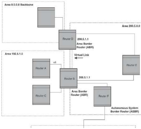
flowchart
graph TD
subgraph "Area 0.0.0 Backbone"
A["Router D"] -->|208.5.1.1\nArea Border Router (ABR)| B["Router E"]
end
subgraph "Area 192.5.1.0"
C["Router A"] -->|c3| B
D["Router B"] -->|206.5.1.1| B
E["Router C"] -->|c3| B
end
F["Router F"] -->| Autonomous System Border Router (ASBR)| B
B -->|Virtual Link| G["Router E"]
In an OSPF point-to-point network, where a direct Layer 3 connection exists between a single pair of OSPF routers, there is no need for Designated and Backup Designated Routers, as is the case in OSPF multi-access networks. Without the need for Designated and Backup Designated routers, a point-to-point network establishes adjacency and converges faster. The neighboring routers become adjacent whenever they can communicate directly. In contrast, in broadcast and non-broadcast multi-access (NBMA) networks, the Designated Router and Backup Designated Router become adjacent to all other routers attached to the network.
To configure an OSPF point-to-point link, refer to "Configuring an OSPF point-to-point link" on page 963.
Designated routers in multi-access networks
In a network that has multiple routers attached, OSPF elects one router to serve as the designated router (DR) and another router on the segment to act as the backup designated router (BDR). This arrangement minimizes the amount of repetitive information that is forwarded on the network by forwarding all messages to the designated router and backup designated routers responsible for forwarding the updates throughout the network.
Designated router election in multi-access networks
In a network with no designated router and no backup designated router, the neighboring router with the highest priority is elected as the DR, and the router with the next largest priority is elected as the BDR, as shown in Figure 139
FIGURE 139 Designated and backup router election
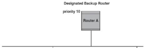
text_image
Designated Backup Router priority 10 Router ANOTE
Priority is a configurable option at the interface level. You can use this parameter to help bias one router as the DR.
FIGURE 140 Backup designated router becomes designated router

flowchart
graph TD
A["Router A"] --> B["Designated Router priority 10"]
B --> C["Router B"]
C --> D["Priority 20"]
D --> E["Router C"]
E --> F["Designated Backup Router priority 5"]
F --> G["Router A"]
If two neighbors share the same priority, the router with the highest router ID is designated as the DR. The router with the next highest router ID is designated as the BDR.
NOTE
By default, the Dell router ID is the IP address configured on the lowest numbered loopback interface. If the Layer 3 Switch does not have a loopback interface, the default router ID is the lowest numbered IP address configured on the device. For more information or to change the router ID, refer to "Changing the router ID" on page 809.
When multiple routers on the same network are declaring themselves as DRs, then both priority and router ID are used to select the designated router and backup designated routers.
When only one router on the network claims the DR role despite neighboring routers with higher
NOTE
For details on how to configure the system to operate with the RFC 2178, refer to "Modifying the OSPF standard compliance setting" on page 962.
Reduction of equivalent AS External LSAs
An OSPF ASBR uses AS External link advertisements (AS External LSAs) to originate advertisements of a route to another routing domain, such as a BGP4 or RIP domain. The ASBR advertises the route to the external domain by flooding AS External LSAs to all the other OSPF routers (except those inside stub networks) within the local OSPF Autonomous System (AS).
In some cases, multiple ASBRs in an AS can originate equivalent LSAs. The LSAs are equivalent when they have the same cost, the same next hop, and the same destination. Dell PowerConnect devices optimize OSPF by eliminating duplicate AS External LSAs in this case. The Layer 3 Switch with the lower router ID flushes the duplicate External LSAs from its database and thus does not flood the duplicate External LSAs into the OSPF AS. AS External LSA reduction therefore reduces the size of the Layer 3 Switch link state database.
This enhancement implements the portion of RFC 2328 that describes AS External LSA reduction. This enhancement is enabled by default, requires no configuration, and cannot be disabled.
Figure 141 shows an example of the AS External LSA reduction feature. In this example, Dell Layer 3 Switches D and E are OSPF ASBRs, and thus communicate route information between the OSPF AS, which contains Routers A, B, and C, and another routing domain, which contains Router F. The other routing domain is running another routing protocol, such as BGP4 or RIP. Routers D, E, and F, therefore, are each running both OSPF and either BGP4 or RIP.
FIGURE 141 AS External LSA reduction
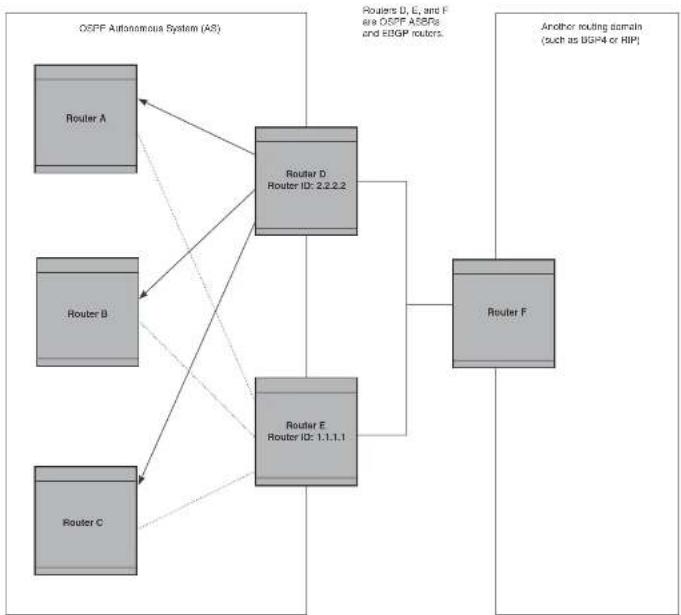
flowchart
graph TD
subgraph OSPF Autonomous System (AS)
A["Router A"] --> D["Router D, Router ID: 2.2.2.2"]
B["Router B"] --> D
C["Router C"] --> E["Router E, Router ID: 1.1.1.1"]
end
D --> F["Router F"]
E --> F
style D fill:#f9f,stroke:#333
style E fill:#f9f,stroke:#333
style F fill:#ccf,stroke:#333
that flush the duplicate AS External LSAs have more memory for other OSPF data. In Figure 141, since Router D has a higher router ID than Router E, Router D floods the AS External LSAs for Router F to Routers A, B, and C. Router E flushes the equivalent AS External LSAs from its database.
Algorithm for AS External LSA reduction
Figure 141 shows an example in which the normal AS External LSA reduction feature is in effect. The behavior changes under the following conditions:
- There is one ASBR advertising (originating) a route to the external destination, but one of the following happens:
• A second ASBR comes on-line - A second ASBR that is already on-line begins advertising an equivalent route to the same destination.
In either case above, the router with the higher router ID floods the AS External LSAs and the other router flushes its equivalent AS External LSAs. For example, if Router D is offline, Router E is the only source for a route to the external routing domain. When Router D comes on-line, it takes over flooding of the AS External LSAs to Router F, while Router E flushes its equivalent AS External LSAs to Router F. - One of the ASBRs starts advertising a route that is no longer equivalent to the route the other ASBR is advertising. In this case, the ASBRs each flood AS External LSAs. Since the LSAs either no longer have the same cost or no longer have the same next-hop router, the LSAs are no longer equivalent, and the LSA reduction feature no longer applies.
- The ASBR with the higher router ID becomes unavailable or is reconfigured so that it is no longer an ASBR. In this case, the other ASBR floods the AS External LSAs. For example, if Router D goes off-line, then Router E starts flooding the AS with AS External LSAs for the route to Router F.
Support for OSPF RFC 2328 Appendix E
Dell PowerConnect devices provide support for Appendix E in OSPF RFC 2328. Appendix E
All three networks have the same network address, 10.0.0.0. Without support for RFC 2328 Appendix E, an OSPF router uses the same link state ID, 10.0.0.0, for the LSAs for all three networks. For example, if the router generates an LSA with ID 10.0.0.0 for network 10.0.0.0 255.0.0.0, this LSA conflicts with the LSA generated for network 10.0.0.0 255.255.0.0 or 10.0.0.0 255.255.255.0. The result is multiple LSAs that have the same ID but that contain different route information.
When Appendix E is supported, the router generates the link state ID for a network as follows.
-
Does an LSA with the network address as its ID already exist?
-
No - Use the network address as the ID.
-
Yes - Go to step 2.
-
Compare the networks that have the same network address, to determine which network is more specific. The more specific network is the one that has more contiguous one bits in its network mask. For example, network 10.0.0.0 255.255.0.0 is more specific than network 10.0.0.0 255.0.0.0, because the first network has 16 ones bits (255.255.0.0) whereas the second network has only 8 ones bits (255.0.0.0):
-
For the less specific network, use the networks address as the ID.
- For the more specific network, use the network broadcast address as the ID. The broadcast address is the network address, with all ones bits in the host portion of the address. For example, the broadcast address for network 10.0.0.0 255.255.0.0 is 10.0.255.255.
If this comparison results in a change to the ID of an LSA that has already been generated, the router generates a new LSA to replace the previous one. For example, if the router has already generated an LSA for network with ID 10.0.0.0 for network 10.0.0.0 255.255.255.0, the router must generate a new LSA for the network, if the router needs to generate an LSA for network 10.0.0.0 255.255.0.0 or 10.0.0.0 255.0.0.0.
Dynamic OSPF activation and configuration
OSPF is automatically activated when you enable it. The protocol does not require a software reload.
You also can change the amount of memory allocated to various types of LSA entries. However, these changes require a system reset or reboot.
Dynamic OSPF memory
PowerConnect devices dynamically allocate memory for Link State Advertisements (LSAs) and other OSPF data structures. This eliminates overflow conditions and does not require a reload to change OSPF memory allocation. So long as the Layer 3 Switch has free (unallocated) dynamic memory, OSPF can use the memory.
To display the current allocations of dynamic memory, use the show memory command.
OSPF graceful restart
OSPF graceful restart is a high-availability routing feature that minimizes disruption in traffic forwarding, diminishes route flapping, and provides continuous service during a system restart, including restart events that occur during a switchover, failover, or hitless OS upgrade. During such events, routes remain available between devices.
When OSPF graceful restart is enabled, a restarting router sends special LSAs, called grace LSAs, to its neighbors either before a planned OSPF restart or immediately after an unplanned restart. The grace LSAs specify a grace period for neighbors of the restarting router to continue using the existing routes to and through the router after a restart. When the restarting router comes back up, it continues to use its existing OSPF routes as if nothing happened. In the background, the router releases its neighbors prior to the restart, recalculates its OSPF routes, and replaces existing routes with new routes as necessary. Once the grace period has passed, adjacent routers resume normal operation.
OSPF graceful restart is enabled globally by default. In this configuration, all OSPF neighbors are subject to the graceful restart capability. Neighbor routers must support the helper mode of OSPF graceful restart, which is enabled by default on all PowerConnect Layer 3 switches.
NOTE
If a PowerConnect device is configured for OSPF graceful restart and is intended to be used in
- Define redistribution filters, if desired.
- Enable redistribution, if you defined redistribution filters.
- Modify default global and port parameters as required.
- Modify OSPF standard compliance, if desired.
NOTE
OSPF is automatically enabled without a system reset.
Configuration rules
- Dell PowerConnect devices support a maximum of 676 OSPF interfaces.
• If a router is to operate as an ASBR, you must enable the ASBR capability at the system level.
• Redistribution must be enabled on routers configured to operate as ASBRs. - All router ports must be assigned to one of the defined areas on an OSPF router. When a port is assigned to an area, all corresponding subnets on that port are automatically included in the assignment.
OSPF parameters
You can modify or set the following global and interface OSPF parameters.
Global parameters:
- Modify OSPF standard compliance setting.
- Assign an area.
- Define an area range.
- Define the area virtual link.
- Set global default metric for OSPF.
- Change the reference bandwidth for the default cost of OSDF interfaces
Interface parameters:
- Assign interfaces to an area.
- Define the authentication key for the interface.
- Change the authentication-change interval
- Modify the cost for a link.
- Modify the dead interval.
- Modify MD5 authentication key parameters.
- Modify the priority of the interface.
- Modify the retransmit interval for the interface.
- Modify the transit delay of the interface.
NOTE
When using the CLI, you set global level parameters at the OSPF CONFIG level of the CLI. To reach that level, enter router ospf... at the global CONFIG level. Interface parameters for OSPF are set at the interface CONFIG level using the CLI command, ip ospf...
When using the Web Management Interface, you set OSPF global parameters using the OSPF configuration panel. All other parameters are accessed through links accessed from the OSPF configuration sheet.
Enabling OSPF on the router
When you enable OSPF on the router, the protocol is automatically activated. To enable OSPF on the router, enter the following CLI command.
PowerConnect(config)#router ospf
This command launches you into the OSPF router level where you can assign areas and modify OSPF global parameters.
Syntax: router ospf
If you have disabled the protocol but have not yet saved the configuration to the startup-config file and reloaded the software, you can restore the configuration information by re-entering the command to enable the protocol (for example, router ospf), or by selecting the Web management option to enable the protocol. If you have already saved the configuration to the startup-config file and reloaded the software, the information is gone.
If you are testing an OSPF configuration and are likely to disable and re-enable the protocol, you might want to make a backup copy of the startup-config file containing the protocol configuration information. This way, if you remove the configuration information by saving the configuration after disabling the protocol, you can restore the configuration by copying the backup copy of the startup-config file onto the flash memory.
Resetting OSPF
The clear ip ospf all command globally resets (disables then re-enables) OSPF without deleting the OSPF configuration information. This command is equivalent to entering the commands no router ospf followed by router ospf. Whereas the no router ospf command disables OSPF and removes all the configuration information for the disabled protocol from the running-config, the router ospf command re-enables OSPF and restores the OSPF configuration information.
The clear ip ospf all command is useful If you are testing an OSPF configuration and are likely to disable and re-enable the protocol. This way, you do not have to save the configuration after disabling the protocol, and you do not have to restore the configuration by copying the backup copy of the startup-config file onto the flash memory.
To reset OSPF without deleting the OSPF configuration, enter the following command at the Global CONFIG level or at the Router OSPF level of the CLI.
PowerConnect#clear ip ospf all
Syntax: clear ip ospf all
Assigning OSPF areas
Once OSPF is enabled on the system, you can assign areas. Assign an IP address or number as the area ID for each area. The area ID is representative of all IP addresses (subnets) on a router port.
When an NSSA contains more than one ABR, OSPF elects one of the ABRs to perform the LSA translation for NSSA. OSPF elects the ABR with the highest router ID. If the elected ABR becomes unavailable, OSPF automatically elects the ABR with the next highest router ID to take over translation of LSAs for the NSSA. The election process for NSSA ABRs is automatic.
Example
To set up the OSPF areas shown in Figure 138 on page 923, enter the following commands.
PowerConnect(config-ospf-router)#area 192.5.0.0
PowerConnect(config-ospf-router)#area 200.5.0.0
PowerConnect(config-ospf-router)#area 195.5.0.0
PowerConnect(config-ospf-router)#area 0.0.0.0
PowerConnect(config-ospf-router)#write memory
Syntax: area
The
NOTE
You can assign one area on a router interface. For example, if the system or chassis module has 16 ports, 16 areas are supported on the chassis or module.
Assigning a totally stubby area
By default, the Layer 3 Switch sends summary LSAs (LSA type 3) into stub areas. You can further reduce the number of link state advertisements (LSAs) sent into a stub area by configuring the Layer 3 Switch to stop sending summary LSAs (type 3 LSAs) into the area. You can disable the summary LSAs when you are configuring the stub area or later after you have configured the area.
This feature disables origination of summary LSAs, but the Layer 3 Switch still accepts summary LSAs from OSPF neighbors and floods them to other neighbors. The Layer 3 Switch can form adjacencies with other routers regardless of whether summarization is enabled or disabled for areas on each router.
When you enter a command or apply a Web management option to disable the summary LSAs, the
The stub
The no-summary parameter applies only to stub areas and disables summary LSAs from being sent into the area.
NOTE
You can assign one area on a router interface. For example, if the system or chassis module has 16 ports, 16 areas are supported on the chassis or module.
Assigning a Not-So-Stubby Area (NSSA)
The OSPF Not-So-Stubby Area (NSSA) feature enables you to configure OSPF areas that provide the benefits of stub areas, but that also are capable of importing external route information. OSPF does not flood external routes from other areas into an NSSA, but does translate and flood route information from the NSSA into other areas such as the backbone.
NSSAs are especially useful when you want to summarize Type-5 External LSAs (external routes) before forwarding them into an OSPF area. The OSPF specification (RFC 2328) prohibits summarization of Type-5 LSAs and requires OSPF to flood Type-5 LSAs throughout a routing domain. When you configure an NSSA, you can specify an address range for aggregating the external routes that the NSSA's ABR exports into other areas.
The Dell implementation of NSSA is based on RFC 1587.
Figure 142 shows an example of an OSPF network containing an NSSA.
FIGURE 142 OSPF network containing an NSSA
text_image
RIP Domain —The ABR translates the Type-7 LSAs into Type-5 LSAs. If an area range is configured for the NSSA, the ABR also summarizes the LSAs into an aggregate LSA before flooding the Type-5 LSAs into the backbone.
Since the NSSA is partially "stubby" the ABR does not flood external LSAs from the backbone into the NSSA. To provide access to the rest of the Autonomous System (AS), the ABR generates a default Type-7 LSA into the NSSA.
Configuring an NSSA
To configure OSPF area 1.1.1.1 as an NSSA, enter the following commands.
PowerConnect(config)#router ospf
PowerConnect(config-ospf-router)†area 1.1.1.1 nssa 1
PowerConnect(config-ospf-router) + write memory
Syntax: area
The
The nssa
NOTE
The Layer 3 Switch does not inject the default route into an NSSA by default.
NOTE
You can assign one area on a router interface. For example, if the system or chassis module has 16 ports, 16 areas are supported on the chassis or module.
To configure additional parameters for OSPF interfaces in the NSSA, use the ip ospf area... command at the interface level of the CLI.
Configuring a summary address for the NSSA
The
Assigning an area range (optional)
You can assign a range for an area, but it is not required. Ranges allow a specific IP address and mask to represent a range of IP addresses within an area, so that only that reference range address is advertised to the network, instead of all the addresses within that range. Each area can have up to 32 range addresses.
Example
To define an area range for subnets on 193.45.5.1 and 193.45.6.2, enter the following commands.
PowerConnect(config)#router ospf
PowerConnect(config-ospf-router)#area 192.45.5.1 range 193.45.0.0 255.255.0.0
PowerConnect(config-ospf-router)†area 193.45.6.2 range 193.45.0.0 255.255.0.0
Syntax: area
The
The range
The
Assigning interfaces to an area
Once you define OSPF areas, you can assign interfaces to the areas. All router ports must be assigned to one of the defined areas on an OSPF router. When a port is assigned to an area, all corresponding subnets on that port are automatically included in the assignment.
To assign interface 1/8 to area 195.5.0.0 and then save the changes enter the following
- ip ospf cost
• ip ospf dead-interval - ip ospf hello-interval
- ip ospf md5-authentication key-activation-wait-time
| key-id [0 | 1] key - ip ospf passive
- ip ospf priority
• Ip ospf retransmit-interval - ip ospf transmit-delay
For a complete description of these parameters, see the summary of OSPF port parameters in the next section.
OSPF interface parameters
The following parameters apply to OSPF interfaces.
Area: Assigns an interface to a specific area. You can assign either an IP address or number to represent an OSPF Area ID. If you assign a number, it can be any value from 0 through 2,147,483,647.
Auth-change-wait-time: OSPF gracefully implements authentication changes to allow all routers to implement the change and thus prevent disruption to neighbor adjacencies. During the authentication-change interval, both the old and new authentication information is supported. The default authentication-change interval is 300 seconds (5 minutes). You change the interval to a value from 0 through 14400 seconds.
Authentication-key: OSPF supports three methods of authentication for each interface—none, simple password, and MD5. Only one method of authentication can be active on an interface at a time. The default authentication value is none, meaning no authentication is performed.
The simple password method of authentication requires you to configure an alphanumeric password on an interface. The simple password setting takes effect immediately. All OSPF packets transmitted on the interface contain this password. Any OSPF packet received on the interface is checked for this password. If the password is not present, then the packet is dropped.
MD5-authentication activation wait time: The number of seconds the Layer 3 Switch waits until placing a new MD5 key into effect. The wait time provides a way to gracefully transition from one MD5 key to another without disturbing the network. The wait time can be from 0 through 14400 seconds. The default is 300 seconds (5 minutes).
MD5-authentication key ID and key: A method of authentication that requires you to configure a key ID and an MD5 key. The key ID is a number from 1 through 255 and identifies the MD5 key that is being used. The MD5 key consists of up to 16 alphanumeric characters. The MD5 is encrypted and included in each OSPF packet transmitted.
Passive: When you configure an OSPF interface to be passive, that interface does not send or receive OSPF route updates. By default, all OSPF interfaces are active and thus can send and receive OSPF route information. Since a passive interface does not send or receive route information, the interface is in effect a stub network. OSPF interfaces are active by default.
NOTE
This option affects all IP subnets configured on the interface. If you want to disable OSPF updates only on some of the IP subnets on the interface, use the ospf-ignore or ospf-passive parameter with the ip address command. Refer to "Assigning an IP address to an Ethernet port" on page 800.
Priority: Allows you to modify the priority of an OSPF router. The priority is used when selecting the designated router (DR) and backup designated routers (BDRs). The value can be from 0 through 255. The default is 1. If you set the priority to 0, the Layer 3 Switch does not participate in DR and BDR election.
Retransmit-interval: The time between retransmissions of link-state advertisements (LSAs) to adjacent routers for this interface. The value can be from 0 through 3600 seconds. The default is 5 seconds.
Transit-delay: The time it takes to transmit Link State Update packets on this interface. The value can be from 0 through 3600 seconds. The default is 1 second.
Encrypted display of the authentication string or MD5 authentication key
The optional 0 | 1 parameter with the authentication-key and md5-authentication key-id parameters affects encryption.
For added security, PowerConnect devices encrypt display of the password or authentication
NOTE
If you want the software to assume that the value you enter is the clear-text form, and to encrypt display of that form, do not enter 0 or 1. Instead, omit the encryption option and allow the software to use the default behavior.
If you specify encryption option 1, the software assumes that you are entering the encrypted form of the password or authentication string. In this case, the software decrypts the password or string you enter before using the value for authentication. If you accidentally enter option 1 followed by the clear-text version of the password or string, authentication will fail because the value used by the software will not match the value you intended to use.
Changing the timer for OSPF authentication changes
When you make an OSPF authentication change, the software uses the authentication-change timer to gracefully implement the change. The software implements the change in the following ways:
- Outgoing OSPF packets – After you make the change, the software continues to use the old authentication to send packets, during the remainder of the current authentication-change interval. After this, the software uses the new authentication for sending packets.
- Inbound OSPF packets – The software accepts packets containing the new authentication and continues to accept packets containing the older authentication for two authentication-change intervals. After the second interval ends, the software accepts packets only if they contain the new authentication key.
The default authentication-change interval is 300 seconds (5 minutes). You change the interval to a value from 0 through 14400 seconds.
OSPF provides graceful authentication change for all the following types of authentication changes in OSPF:
- Changing authentication methods from one of the following to another of the following:
- Simple text password
- MD5 authentication
Block flooding of outbound LSAs on specific OSPF interfaces
By default, the Layer 3 Switch floods all outbound LSAs on all the OSPF interfaces within an area. You can configure a filter to block outbound LSAs on an OSPF interface. This feature is particularly useful when you want to block LSAs from some, but not all, of the interfaces attached to the area.
After you apply filters to block the outbound LSAs, the filtering occurs during the database synchronization and flooding.
If you remove the filters, the blocked LSAs are automatically re-flooded. You do not need to reset OSPF to re-flood the LSAs.
NOTE
You cannot block LSAs on virtual links.
To apply a filter to an OSPF interface to block flooding of outbound LSAs on the interface, enter the following commands at the Interface configuration level for that interface.
PowerConnect(config-if-1/1)#ip ospf database-filter all out
PowerConnect{config-if-1/1}#clear ip ospf all
The first command in this example blocks all outbound LSAs on the OSPF interface configured on port 1/1. The second command resets OSPF and places the command into effect immediately.
Syntax: [no] ip ospf database-filter all out
To remove the filter, enter a command such as the following.
PowerConnect{config-1f-1/1}#no ip ospf database-filter all out
Configuring an OSPF non-broadcast interface
Layer 3 switches support Non-Broadcast Multi-Access (NBMA) networks. This feature enables you to configure an interface on a Dell PowerConnect device to send OSPF traffic to its neighbor as unicast packets rather than broadcast packets.
OSPF routers generally use broadcast packets to establish neighbor relationships and broadcast route updates on Ethernet and virtual interfaces (VEs). In this release, as an alternative, you can
PowerConnect(config)#int ve 20
PowerConnect(config-vif-20)#ip ospf area 0
PowerConnect(config-vif-20)#ip ospf network non-broadcast
PowerConnect(config-vif-20)#exit
Syntax: [no] ip ospf network non-broadcast
The following commands specify 1.1.20.1 as an OSPF neighbor address. The address specified must be in the same subnet as a non-broadcast interface.
PowerConnect(config)#router ospf
PowerConnect(config ospf router)#neighbor 1.1.20.1
For example, to configure the feature in a network with three routers connected by a hub or switch, each router must have the linking interface configured as a non-broadcast interface, and both of the other routers must be specified as neighbors.
The output of the show ip ospf interface command has been enhanced to display information about non-broadcast interfaces and neighbors that are configured in the same subnet.
Example
PowerConnect+show ip ospf interface
v20,OSPF enabled
IP Address 1.1.20.4, Area 0
CSPF state BD, Pri 1, Cost 1, Options 2, Type non-broadcast Events 6
Timers(sec): Transit 1, Retrans 5, Hello 10, Dead 40
DR: Router ID 1.1.13.1 Interface Address 1.1.20.5
EDR: Router ID 2.2.2.1 Interface Address 1.1.20.4
Neighbor Count - 1, Adjacent Neighbor Count-2
Non-broadcast neighbor config: 1.1.20.1, 1.1.20.2, 1.1.20.3, 1.1.20.5,
Neighbor: 1.1.20.
Authentication-Key: None
MD5 Authentication: Key None, Key-Id None, Auth-change-wait-time 300
In the Type field, "non-broadcast" indicates that this is a non-broadcast interface. When the interface type is non-broadcast, the Non-broadcast neighbor config field displays the neighbors that are configured in the same subnet. If no neighbors are configured in the same subnet, a message such as the following is displayed.
***Warning! no non-broadcast neighbor config in 1.1.100.1 255.255.255.0
NOTE
By default, the Dell router ID is the IP address configured on the lowest numbered loopback interface. If the Layer 3 Switch does not have a loopback interface, the default router ID is the lowest numbered IP address configured on the device. For more information or to change the router ID, refer to "Changing the router ID" on page 809.
NOTE
When you establish an area virtual link, you must configure it on both of the routers (both ends of the virtual link).
FIGURE 143 Defining OSPF virtual links within a network
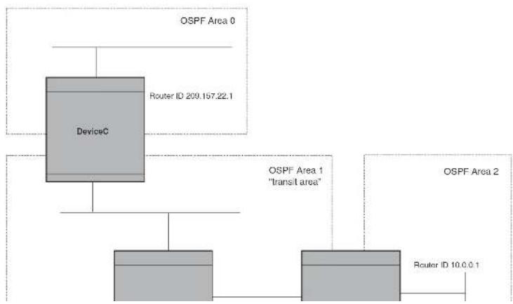
flowchart
graph TD
A["DeviceC"] --> B["OSPF Area 0"]
A --> C["OSPF Area 1 "transit area""]
A --> D["OSPF Area 2"]
B --> E["Router ID 209.157.22.1"]
C --> F["Router ID 10.0.0.1"]
PowerConnectC(config-ospf-router)↑area 1 virtual-link 10.0.0.1 PowerConnectC(config-ospf-router)↑write memory
Syntax: area
The area
The
Refer to "Modifying virtual link parameters" on page 944 for descriptions of the optional parameters.
Modifying virtual link parameters
OSPF has some parameters that you can modify for virtual links. Notice that these are the same parameters as the ones you can modify for physical interfaces.
You can modify default values for virtual links using the following CLI command at the OSPF router level of the CLI, as shown in the following syntax.
Syntax: area
[dead-interval
[hello-interval
[retransmit-interval
The parameters are described in the next section.
Virtual link parameter descriptions
You can modify the following virtual link interface parameters.
Authentication Key: This parameter allows you to assign different authentication methods on a port-by-port basis. OSPF supports three methods of authentication for each interface—none, simple password, and MD5. Only one method of authentication can be active on an interface at a
MD5 Authentication Wait Time: This parameter determines when a newly configured MD5 authentication key is valid. This parameter provides a graceful transition from one MD5 key to another without disturbing the network. All new packets transmitted after the key activation wait time interval use the newly configured MD5 Key. OSPF packets that contain the old MD5 key are accepted for up to five minutes after the new MD5 key is in operation.
The range for the key activation wait time is from 0 through 14400 seconds. The default value is 300 seconds.
Hello Interval: The length of time between the transmission of hello packets. The range is 1 through 65535 seconds. The default is 10 seconds.
Retransmit Interval: The interval between the re-transmission of link state advertisements to router adjacencies for this interface. The range is 0 through 3600 seconds. The default is 5 seconds.
Transmit Delay: The period of time it takes to transmit Link State Update packets on the interface. The range is 0 through 3600 seconds. The default is 1 second.
Dead Interval: The number of seconds that a neighbor router waits for a hello packet from the current router before declaring the router down. The range is 1 through 65535 seconds. The default is 40 seconds.
Encrypted display of the authentication string or MD5 authentication key
The optional 0 | 1 parameter with the authentication-key and md5-authentication key-id parameters affects encryption.
For added security, PowerConnect devices encrypt display of the password or authentication string. Encryption is enabled by default. The software also provides an optional parameter to disable encryption of a password or authentication string, on an individual OSPF area or OSPF interface basis.
When encryption of the passwords or authentication strings is enabled, they are encrypted in the CLI regardless of the access level you are using. In the Web Management Interface, the passwords or authentication strings are encrypted at the read-only access level but are visible at the read-write access level.
The encryption option can be omitted (the default) or can be one of the following:
Changing the reference bandwidth for the cost on OSPF interfaces
Each interface on which OSPF is enabled has a cost associated with it. The Layer 3 Switch advertises its interfaces and their costs to OSPF neighbors. For example, if an interface has an OSPF cost of ten, the Layer 3 Switch advertises the interface with a cost of ten to other OSPF routers.
By default, an interface OSPF cost is based on the port speed of the interface. The cost is calculated by dividing the reference bandwidth by the port speed. The default reference bandwidth is 100 Mbps, which results in the following default costs:
• 10 Mbps port - 10
- All other port speeds - 1
You can change the reference bandwidth, to change the costs calculated by the software.
The software uses the following formula to calculate the cost.
Cost = reference-bandwidth/interface-speed
If the resulting cost is less than 1, the software rounds the cost up to 1. The default reference bandwidth results in the following costs:
• 10 Mbps port cost = 100/10 = 10
• 100 Mbps port cost = 100/100 = 1
• 1000 Mbps port cost = 100/1000 = 0.10, which is rounded up to 1
• 155 Mbps port cost = 100/155 = 0.65, which is rounded up to 1
- 622 Mbps port cost = 100/622 = 0.16, which is rounded up to 1
• 2488 Mbps port cost = 100/2488 = 0.04, which is rounded up to 1
For 10 Gbps OSPF interfaces, in order to differentiate the costs between 100 Mbps, 1000 Mbps, and 10,000 Mbps interfaces, you can set the auto-cost reference bandwidth to 10000, whereby each slower link is given a higher cost, as follows:
• 10 Mbps port cost = 10000/10 = 1000
• 100 Mbps port cost = 10000/100 = 100
■ 1000 Mbps port cost = 10000/1000 - 10
Interface types to which the reference bandwidth does not apply
Some interface types are not affected by the reference bandwidth and always have the same cost regardless of the reference bandwidth in use:
- The cost of a loopback interface is always 0.
- The cost of a virtual link is calculated using the Shortest Path First (SPF) algorithm and is not affected by the auto-cost feature.
• The bandwidth for tunnel interfaces is 9 Kbps and is not affected by the auto-cost feature.
Changing the reference bandwidth
To change the reference bandwidth, enter a command such as the following at the OSPF configuration level of the CLI.
PowerConnect (config-ospf-router) auto-cost reference-bandwidth 500
The reference bandwidth specified in this example results in the following costs:
• 10 Mbps port cost = 500/10 = 50
• 100 Mbps port cost = 500/100 = 5
- 1000 Mbps port cost = 500/1000 = 0.5, which is rounded up to 1
• 155 Mbps port cost = 500/155 = 3.23, which is rounded up to 4
- 622 Mbps port cost = 500/622 = 0.80, which is rounded up to 1
• 2488 Mbps port cost = 500/2488 = 0.20, which is rounded up to 1
The costs for 10 Mbps, 100 Mbps, and 155 Mbps ports change as a result of the changed reference bandwidth. Costs for higher-speed interfaces remain the same.
Syntax: [no] auto-cost reference-bandwidth
The
In Figure 144 on page 948, an administrator wants to configure the PowerConnect Layer 3 Switch acting as the ASBR (Autonomous System Boundary Router) between the RIP domain and the OSPF domain to redistribute routes between the two domains.
NOTE
The ASBR must be running both RIP and OSPF protocols to support this activity.
To configure for redistribution, define the redistribution tables with deny and permit redistribution filters. Use the deny redistribute and permit redistribute commands for OSPF at the OSPF router level.
NOTE
Do not enable redistribution until you have configured the redistribution filters. If you enable redistribution before you configure the redistribution filters, the filters will not take affect and all routes will be distributed.
FIGURE 144 Redistributing OSPF and static routes to RIP routes
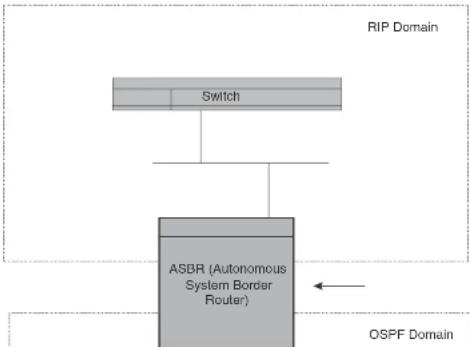
flowchart
graph TD
A["RIP Domain"] --> B["Switch"]
B --> C["ASBR (Autonomous System Border Router)"]
C --> D["OSPF Domain"]
D --> C
NOTE
Redistribution is permitted for all routes by default, so the permit redistribute 1 all command in the example above is shown for clarity but is not required.
You also have the option of specifying import of just OSPF, BGP4, or static routes, as well as specifying that only routes for a specific network or with a specific cost (metric) be imported, as shown in the following command syntax.
Syntax: deny | permit redistribute
Example
To redistribute RIP, static, and BGP4 routes into OSPF, enter the following commands on the Layer 3 Switch acting as an ASBR.
PowerConnectASBR(config)#router ospf PowerConnectASBR(config-ospf-router)#permit redistribute 1 all PowerConnectASBR(config ospf router)#write memory
Syntax: deny | permit redistribute
NOTE
Redistribution is permitted for all routes by default, so the permit redistribute 1 all command in the example above is shown for clarity but is not required.
You also have the option of specifying import of just OSPF, BGP4, or static routes, as well as specifying that only routes for a specific network or with a specific cost (metric) be imported, as shown in the following command syntax.
For example, to enable redistribution of RIP and static IP routes into OSPF, enter the following commands.
PowerConnect(config)#router ospf PowerConnect(config-ospf-router)#distribution rip PowerConnect(config-ospf-router)#distribution static PowerConnect(config-ospf-router)#write memory
Preventing specific OSPF routes from being installed in the IP route table
By default, all OSPF routes in the OSPF route table are eligible for installation in the IP route table. You can configure a distribution list to explicitly deny specific routes from being eligible for installation in the IP route table.
NOTE
This feature does not block receipt of LSAs for the denied routes. The Layer 3 Switch still receives the routes and installs them in the OSPF database. The feature only prevents the software from installing the denied OSPF routes into the IP route table.
To configure an OSPF distribution list:
- Configure a standard or extended ACL that identifies the routes you want to deny. Using a standard ACL lets you deny routes based on the destination network, but does not filter based on the network mask. To also filter based on the destination network network mask, use an extended ACL.
- Configure an OSPF distribution list that uses the ACL as input.
NOTE
If you change the ACL after you configure the OSPF distribution list, you must clear the IP route table to place the changed ACL into effect. To clear the IP route table, enter the clear ip route command at the Privileged EXEC level of the CLI.
The following sections show how to use the CLI to configure an OSPF distribution list. Separate examples are provided for standard and extended ACLs.
NOTE
The examples show named ACLs. However, you also can use a numbered ACL as input to the OSPF distribution list.
Using a standard ACL as input to the distribution list
Syntax: deny | permit
The
The in command applies the ACL to incoming route updates.
The
If you do not specify an interface type and interface number, the device applies the OSPF distribution list to all incoming route updates.
The deny | permit parameter indicates whether packets that match the policy are dropped or forwarded.
The
The
If you want the policy to match on all destination networks, enter any any.
If you prefer to specify the wildcard (mask value) in Classless Interdomain Routing (CIDR) format, you can enter a forward slash after the IP address, then enter the number of significant bits in the mask. For example, you can enter the CIDR equivalent of "4.0.0.0 0.255.255.255" as "4.0.0.0/8". The CLI automatically converts the CIDR number into the appropriate ACL mask (where zeros instead of ones are the significant bits) and changes the non-significant portion of the IP address into zeros.
NOTE
If you enable the software to display IP subnet masks in CIDR format, the mask is saved in the file in
PowerConnect(config)#ip access-list extended no_ip
PowerConnect(config-ext-nACL)†deny ip 4.0.0.0 0.255.255.255 255.255.0.0 0.0.255.255
PowerConnect(config-ext-nACL)↑permit ip any any PowerConnect(config-ext-nACL)↑exit
PowerConnect(config)#router asp
The first three commands configure an extended ACL that denies routes to any 4.x.x.x destination network with a 255.255.0.0 network mask and allows all other routes for eligibility to be installed in the IP route table. The last three commands change the CLI to the OSPF configuration level and configure an OSPF distribution list that uses the ACL as input. The distribution list prevents routes to any 4.x.x.x destination network with network mask 255.255.0.0 from entering the IP route table. The distribution list does not prevent the routes from entering the OSPF database.
Syntax: [no] ip access-list extended
Syntax: deny | permit
The
The deny | permit parameter indicates whether packets that match the policy are dropped or forwarded.
The
Because this ACL is input to an OSPF distribution list, the
The
If you want the policy to match on all network addresses, enter any any.
If you prefer to specify the wildcard (mask value) in Classless Interdomain Routing (CIDR) format,
Because this ACL is input to an OSPF distribution list, the
The
If you want the policy to match on all network masks, enter any any.
Modifying the default metric for redistribution
The default metric is a global parameter that specifies the cost applied to all OSPF routes by default. The default value is 10. You can assign a cost from 1 through 15.
NOTE
You also can define the cost on individual interfaces. The interface cost overrides the default cost.
To assign a default metric of 4 to all routes imported into OSPF, enter the following commands.
PowerConnect(config)#router ospf
PowerConnect(config-ospf-router)#default-metric 4
Syntax: default-metric
The
Enabling route redistribution
To enable route redistribution, use one of the following methods.
NOTE
Do not enable redistribution until you have configured the redistribution filters. Otherwise, you might accidentally overload the network with routes you did not intend to redistribute.
To enable redistribution of RIP and static IP routes into OSPF, enter the following commands.
PowerConnect(config)#ip route 1.1.0.0 255.255.0.0 207.95.7.30 PowerConnect(config)#ip route 1.2.0.0 255.255.0.0 207.95.7.30 PowerConnect(config)#ip route 1.3.0.0 255.255.0.0 207.95.7.30 PowerConnect(config)#ip route 4.1.0.0 255.255.0.0 207.95.6.30 PowerConnect(config)#ip route 4.2.0.0 255.255.0.0 207.95.6.30 PowerConnect(config)#ip route 4.3.0.0 255.255.0.0 207.95.6.30 PowerConnect(config)#ip route 4.4.0.0 255.255.0.0 207.95.6.30 5 PowerConnect(config)#route-map abc permit 1 PowerConnect(config-routermap abc)#match metric 5 PowerConnect(config-routermap abc)#set metric 8 PowerConnect(config-routermap abc)#router ospf PowerConnect(config-ospf-router)#distribution static route-map abc
The commands in this example configure some static IP routes, then configure a route map and use the route map for redistributing static IP routes into OSPF.
The ip route commands configure the static IP routes. The route-map command begins configuration of a route map called "abc". The number indicates the route map entry (called the "instance") you are configuring. A route map can contain multiple entries. The software compares packets to the route map entries in ascending numerical order and stops the comparison once a match is found.
The match command in the route map matches on routes that have 5 for their metric value (cost). The set command changes the metric in routes that match the route map to 8.
The redistribution static command enables redistribution of static IP routes into OSPF, and uses route map "abc" to control the routes that are redistributed. In this example, the route map allows a static IP route to be redistributed into OSPF only if the route has a metric of 5, and changes the metric to 8 before placing the route into the OSPF route table.
Syntax: [no] redistribution bgp | connected | rip | static [route-map
The bgp | connected | rip | static parameter specifies the route source.
The route-map
- match ip address | next-hop
- match metric
NOTE
For an external route that is redistributed into OSPF through a route map, the metric value of the route remains the same unless the metric is set by a set metric command inside the route map. The default-metric
The following command shows the result of the redistribution filter. Because only one of the static IP routes configured above matches the route map, only one route is redistributed. Notice that the route metric is 5 before redistribution but is 8 after redistribution.
PowerConnect#show ip ospf database external extensive
| Index | Aging | LS ID | Router | Netmask | Metric | Flag |
| 1 | 2 | 4.4.0.0 | 10.10.10.60 | ffff0000 | 80000008 | 0000 |
Disabling or re-enabling load sharing
Dell routers can load share among up to eight equal-cost IP routes to a destination. By default, IP load sharing is enabled. The default is 4 equal-cost paths but you can specify from 2 to 6 paths.
The router software can use the route information it learns through OSPF to determine the paths and costs. Figure 145 shows an example of an OSPF network containing multiple paths to a destination (in this case, R1).
FIGURE 145 Example OSPF network with four equal-cost paths
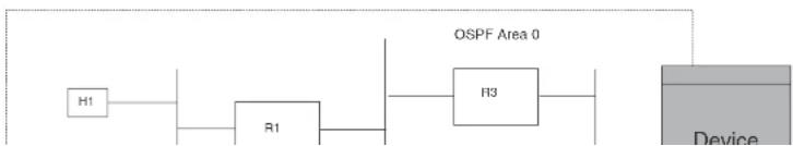
flowchart
graph LR
H1 --> R1
R1 --> H3
H3 --> Device
OSPF_Area_0["OSPF Area 0"]
• PowerConnect->R4
- PowerConnect->R5
- PowerConnect->R6
Normally, the Dell PowerConnect switch will choose the path to the R1 with the lower metric. For example, if R3 metric is 1400 and R4 metric is 600, the Dell PowerConnect switch will always choose R4.
However, suppose the metric is the same for all four routers in this example. If the costs are the same, the switch now has four equal-cost paths to R1. To allow the switch to load share among the equal cost routes, enable IP load sharing. The software supports four equal-cost OSPF paths by default when you enable load sharing. You can specify from 2 to 6 paths.
NOTE
The Dell PowerConnect switch is not source routing in these examples. The switch is concerned only with the paths to the next-hop routers, not the entire paths to the destination hosts.
OSPF load sharing is enabled by default when IP load sharing is enabled. To configure IP load sharing parameters, refer to "Configuring IP load sharing" on page 829.
Configuring external route summarization
When the Layer 3 Switch is an OSPF Autonomous System Boundary Router (ASBR), you can configure it to advertise one external route as an aggregate for all redistributed routes that are covered by a specified address range.
When you configure an address range, the range takes effect immediately. All the imported routes are summarized according to the configured address range. Imported routes that have already been advertised and that fall within the range are flushed out of the AS and a single route corresponding to the range is advertised.
If a route that falls within a configured address range is imported by the Layer 3 Switch, no action is taken if the Layer 3 Switch has already advertised the aggregate route; otherwise the Layer 3 Switch advertises the aggregate route. If an imported route that falls with in a configured address range is removed by the Layer 3 Switch, no action is taken if there are other imported routes that fall with in the same address range otherwise the aggregate route is flushed.
PowerConnect(config-ospf-router)↑summary-address 10.1.0.0 255.255.0.0
The command in this example configures summary address 10.1.0.0, which includes addresses 10.1.1.0, 10.1.2.0, 10.1.3.0, and so on. For all of these networks, only the address 10.1.0.0 (the parent route) is advertised in external LSAs. However, if the parent route has not been configured with a summary address, or if the summary address for the parent route is configured after the child route, the Layer 3 switch will advertise all routes. For example:
router ospf
summary-address 10.1.1.0 255.255.0.0 -> Advertised
summary-address 10.1.2.0 255.255.0.0 -> Advertised
summary-address 10.0.0.0 255.0.0.0 -> Advertised
Syntax: summary-address
The
The
To display the configured summary addresses, use the show ip ospf config command at any level of the CLI. The summary addresses display at the bottom of the output as shown in the following example.
PowerConnect#show ip ospf config
some lines omitted for brevity...
OSPF Redistribution Address Ranges currently defined:
Range-Address Subnetmask
1.0.0.0 255.0.0.0 1.0.1.0 255.055.0
1.0,1.0 255,255,255.0 1.0,2.0 255,255,255.0
Syntax: show ip ospf config
Configuring default route origination
When the Layer 3 Switch is an OSPF Autonomous System Boundary Router (ASRR), you can