58G495 - Saw Graphite - Free user manual and instructions
Find the device manual for free 58G495 Graphite in PDF.


| Product Type | Plunge Cut Track Saw |
| Model | 58G495 |
| Brand | Graphite |
| Power Supply | 230 V AC, 50 Hz |
| Rated Power | 1200 W |
| No-Load Speed | 2200 – 5200 min⁻¹ |
| Blade Diameter | 165 mm |
| Blade Bore | 20 mm |
| Cutting Depth (without guide rail) | 0 – 57 mm |
| Cutting Depth (with guide rail) | 0 – 52 mm |
| Bevel Cutting Range | 0° – 47° |
| Weight | 4.6 kg |
| Protection Class | II (Double insulation) |
| Sound Pressure Level | 90.73 dB(A) (K=3 dB) |
| Sound Power Level | 101.73 dB(A) (K=3 dB) |
| Vibration (main handle) | 3.249 m/s² (K=1.5 m/s²) |
| Vibration (auxiliary handle) | 2.828 m/s² (K=1.5 m/s²) |
| Safety Features | Blade guard, spindle lock, lock button, kickback protection |
| Dust Extraction | Rotatable dust outlet for vacuum connection |
| Guide Rail Compatibility | Yes (guide rail not included) |
| Speed Control | Electronic wheel (1-7) |
| Power Indicator | LED on main handle |
Frequently Asked Questions - 58G495 Graphite
User questions about 58G495 Graphite
0 question about this device. Answer the ones you know or ask your own.
Ask a new question about this device
Download the instructions for your Saw in PDF format for free! Find your manual 58G495 - Graphite and take your electronic device back in hand. On this page are published all the documents necessary for the use of your device. 58G495 by Graphite.
USER MANUAL 58G495 Graphite

INSTRUKCJA ORYGINALNA (OBSŁUGI) PILARKO - ZAGŁĘBIARKA 58G495
UWAGA: PRZED PRZYSTĄPIENIEM DO UŻYTKOWANIA ELEKTRONARZĘDZIA NALEŻY UWAŻNIE PRZECZYTAĆ NINIEJSZA INSTRUKCJE I ZACHOWAĆ JA DO DALSZEGO WYKORZYSTANIA.
SZCZEGÓŁOWE PRZEPISY BEZPIECZEŃSTWA
SZCZEGÓŁOWE BEZPIECZEŃSTWO UŻYTKOWANIA PILAREK TARCZOWYCH WRZYNAJĄCYCH BEZ KLINA ROZSZCZEPIAJĄCEGO


TRANSLATION OF THE ORIGINAL INSTRUCTIONS
PLUNGE CUT TRACK SAW
58G495
CAUTION: BEFORE USING THE POWER TOOL READ THIS MANUAL CAREFULLY AND KEEP IT FOR FUTURE REFERENCE.
DETAILED SAFETY REGULATIONS
DETAILS OF OPERATIONAL SAFETY FOR PLUNGE TYPE SAWS WITHOUT RIVING KNIFE
CAUTION:
Neglecting the instructions specified in the below warnings about risks and guidelines for safety of use may cause risks of electric shock, fire and/or serious injuries.
Cutting procedures
b. DANGER: Keep hands away from cutting area and the blade. Keep your second hand on auxiliary handle, or motor housing. If both hands are holding the sow, they cannot be cut by the blade.
c. Do not reach underneath the workpiece. The guard cannot protect you from the blade below the workpiece.
d. Adjust the cutting depth to the thickness of the workpiece. Less that a full tooth of the blade teeth should be visible below the workpiece.
e. Never hold piece being cut in your hands or across your leg. Secure the workpiece to a stable platform. It is important to support the work properly to minimize body exposure, blade binding, or loss of control.
f. Hold the power tool by insulated surfaces gripping surfaces only, when performing an operation where the cutting tool may contact hidden wiring or its own cord. Contact with a "live" wire will also make exposed metal parts of the power tool "live" and could give the operator an electric shock.
g. When ripping, always use a rip fence or starting edge guide. This improves the accuracy of cut and reduces the chance of blade binding.
h. Always use blades with correct size and shape (diamond versus round) of arbour holes. Blades that do not match the mounting hardware of the saw will run eccentrically, causing loss of control.
i. Never use damaged or incorrect blade washers or bolts. The blade washers and bolt were specially designed for your saw, for optimum performance and safety of operation.
Kickback causes and related warnings
- Kickback is a sudden reaction to a pinched, bound or misaligned saw blade, causing an uncontrolled saw to lift up and out of the workpiece toward the operator;
- When the blade is pinched or bound tightly by the kerf closing down, the blade stalls and the motor reaction drives the unit rapidly back towards the operator;
- If the blade becomes twisted or misaligned in the cut, the teeth at the back edge of the blade can dig into the top surface of the wood causing the blade to climb out of the kerf and jump back towards the operator.
Kickback is the result of saw misuse and/or incorrect operating procedures or conditions and can be taking proper precautions as given below.
a. Maintain a firm grip with both hands on the saw and position your arms to resist kickback forces. Position your body to either side of the blade, but not in line with the blade. Kickback could cause the saw to jump backwards, but kickback forces can be controlled by the operator, if proper precautions are taken.
b. When blade is binding, or when interrupting a cut for any reason, release the trigger and hold the saw motionless in the material until the blade comes to a complete stop. Never attempt to remove the saw from the work or pull the saw backward while the blade is in motion or kickback may occur. Investigate and take corrective actions to eliminate the cause of blade binding.
c. When restarting a saw in the workpiece, centre the saw blade in the kerf and check that saw teeth are not engaged into the material. If saw blade is binding, it may walk up or cause kickback from the workpiece as the saw is restarted.
d. Support large panels to minimise the risk of blade pinching and kickback. Large panels tend to sag under their own weight. Supports must be placed under the panel on both sides, near the line of cut and near the edge of the panel.
e. Do not use dull or damaged blades. Unsharpened or improperly set blades narrow kerf causing excessive friction, blade binding and kickback.
f. Blade depth and bevel adjusting locking levers must be tight and secure before making cut. If blade adjustment shifts while cutting, it may cause binding and kickback.
g. Use extra caution when sawing into existing walls or other blind areas. The protruding blade may cut objects that can cause kickback. Guard function
a. Check guard for proper closing before each use. Do not operate the saw if guard does not move freely and enclose the blade instantly. Never clamp or tie the guard so that the blade is exposed. If saw is accidentally dropped, guard may be bent. Check to make sure that guard moves freely and does not touch the blade or any other part, in all angles and depths of cut.
b. Check the operation and condition of the guard return spring. If the guard and the spring are not operating properly, they must be serviced before use. Guard may operate sluggishly due to damaged parts, gummy deposits, or a build-up of debris.
c. Assure that the base plate of the saw will not shift while performing the "plunge cut" when the blade bevel setting is not at 90°. Blade shifting sideways will cause binding and likely kick back.
d. Always observe that the guard is covering the blade before placing saw down on bench or floor. An unprotected, coasting blade will cause the saw to walk backwards, cutting whatever is in its path. Be aware of the time it takes for the blade to stop after switch is released.
Additional safety instructions
Precautions
- Do not use damaged or deformed cutting blades.
- Do not use grinding wheels.
- Use only cutting blades that are recommended by the manufacturer and comply with the standard EN 847-1.
- Do not use cutting blades without sintered carbide tips on teeth.
- Dust of certain wood types may be dangerous to health. Direct physical contact with dusts may cause allergic reaction and/or respiratory system diseases of operator or bystanders. Dusts of oak and beech are considered carcinogenic, especially in connection with wood processing substances (wood impregnants).
- Use personal protection measures, such as:
- earmuff protectors to reduce risk of hearing damage,
- eye shield,
- respiratory system protection to reduce risk of harmful dusts inhalation,
- gloves for maintenance of cutting blades and other rough and sharp materials (hold cutting blades by mount hole whenever possible).
Connect dust extraction system when cutting wood.
Safe work and maintenance
- Match cutting blade with material that you plan to cut.
- Never use the saw for cutting materials other than wood and wood-like.
- Do not use the saw without guard or when the guard is blocked.
Floor close to the machine work place must be kept tidy and without
loose materials and protrusions.
- Provide appropriate work place illumination.
- Machine operator must be properly trained for use, operation and working with the machine.
- Use only sharp cutting blades.
- Observe maximum speed indicated on the cutting blade.
- Make sure to use parts in accordance with the manufacturer's instructions.
- Disconnect the saw from power supply when performing maintenance tasks.
- If the power cord gets damaged during operation, disconnect the power supply immediately. DO NOT TOUCH POWER CORD BEFORE DISCONNECTING FROM THE POWER SUPPLY.
- If the saw is equipped with laser, replacement with laser of another type is forbidden and all repairs must be carried out by the service. Do not aim the laser beam at people or animals.
- Do not use the tool in stationary mode. It is not designed for use with sawing table.
- Fix processed material to stable surface and secure with clamps or vice to eliminate shifting. This kind of work piece fixation is safer than holding the work piece in hand.
- Wait until blade comes to a complete stop before putting the power tool away. Cutting blade may jam and cause loss of control over the power tool.
CAUTION! This device is designed to operate indoors.
The design is assumed to be safe, protection measures and additional safety systems are used, nevertheless there is always a small risk of injuries at work.
Explanation of used symbols

1

2

3
4
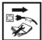
5
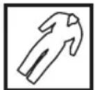
6

7
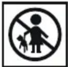
8

9
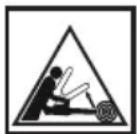
10
- CAUTION! Use precaution measures!
- Read instruction manual, observe warnings and safety conditions therein!
- Protection class 2.
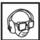
- Use personal protection measures (protective goggles, earmuff protectors, anti-dust mask).
- Disconnect the charger before repairs.
- Use protective clothes.
- Protect the tool from moisture.
- Keep the tool away from children.
- Caution, risk of hand injuries and cutting fingers.
- Danger of kickback.
CONSTRUCTION AND USE
Plunge cut track saw is a hand-held power tool with insulation class II. The tool is driven by single-phase commutator motor with rotational speed reduced with gear transmission. When used with proper equipment it can be used for ripping and cross cutting of wood, furniture chipboards, panels, plywood and similar wood based materials. The tool combines functionality of circular saw and plunge saw, thus allowing to perform plunge cuts to defined depth in abovementioned materials. Such power tool can be used for ripping to defined dimensions along straight line thanks to use of guiding fences.
Range of use covers all areas in renovation tasks. Possibility of dust-free operation with use of vacuum cleaner allows for easier operation in
already finished rooms.

The tool is designed for cutting and dry operation only. Do not use the tool with corundum or diamond discs. Use the power tool in accordance with the manufacturer's instructions only.
DESCRIPTION OF DRAWING PAGES
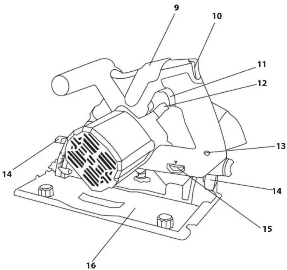
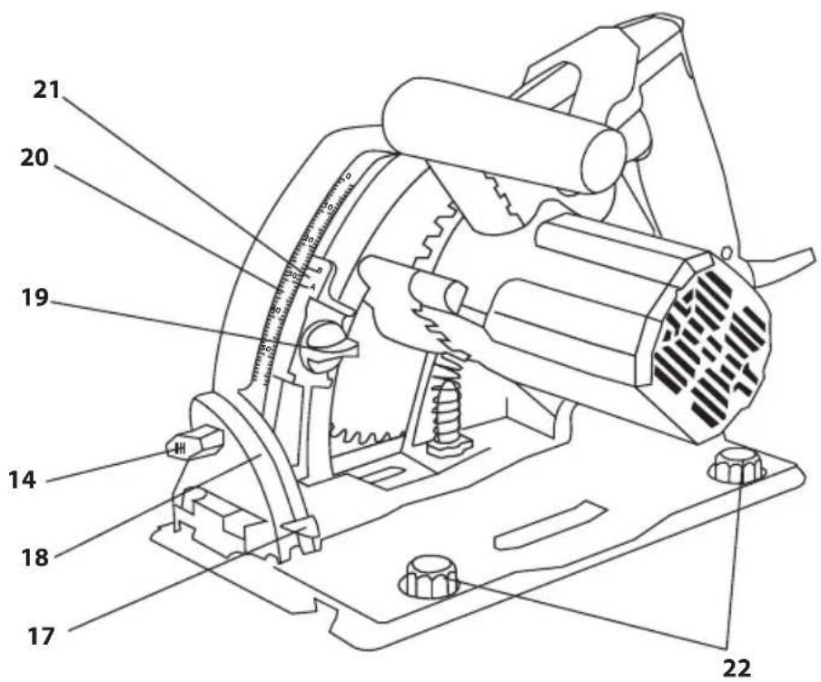
Below enumeration refers to the device elements depicted on the drawing pages of this manual.
-
Dust extraction outlet
-
Main handle
-
Auxiliary handle
-
Cross cut line indicator
-
Mitre cut indicator
-
Guard cut out
-
Cutting blade
-
Cutting blade guard
-
Lock lever
-
Lock button
-
Switch
-
Spindle lock button
-
Power indicator
-
Knob for base position adjustment
-
Wheel for rotational speed control
-
Base
-
Angle indicator
-
Angular scale
-
Cutting depth gauge knob
-
Cutting depth scale
-
A, B cutting depth gauge
-
Rail precision adjustment knobs
-
Guide rail track
-
Anti slip foam
-
Edge rubber
-
Slide strip
-
Connecting rod
-
Fixing groove
-
Pressing screws
-
Fixing clamp
-
Guiding groove
-
Fixing bolt for cutting blade
* Differences may appear between the product and drawing.
MEANING OF SYMBOLS

CAUTION

WARNING

WARNING

INFORMATION
EQUIPMENT AND ACCESSORIES
- Hexagonal key - 1 pce
Plunge cut track saw is equipped with dust extraction outlet (1) that can be rotated, which allows for extraction of sawdust produced when cutting. Whenever more efficient dust extraction is required for health hazardous carcinogenic dusts, attach hose of suction device to the dust extraction outlet (1).
USE OF THE GUIDE RAIL TRACK

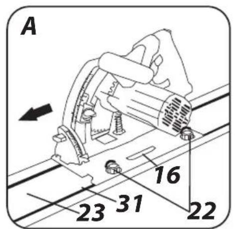
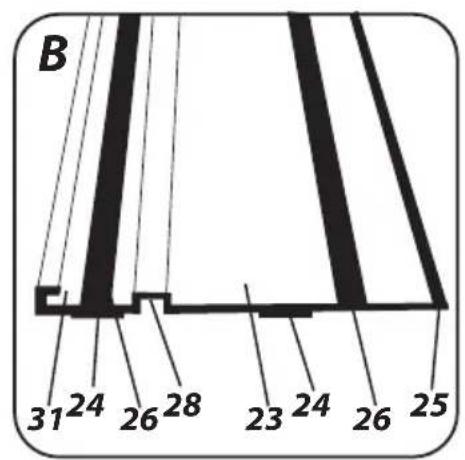
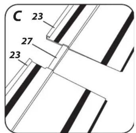
Plunge cut track saw allows for guiding along the guide rail track (23) (fig. A). The guide rail track features anti-slip foam (24) (fig. B) on the bottom of the track to reduce risk of the track shifting during work. Cutting edge is protected with edge rubber (25) to produce clean cut. In the first cut excess of rubber on the edge is removed, thus matching the rubber precisely to the cutting line. The plunge cut track saw moves along the track thanks to the slide strips (26). For greater cutting precision it is possible to join guide rails with each other and fix to processed material.
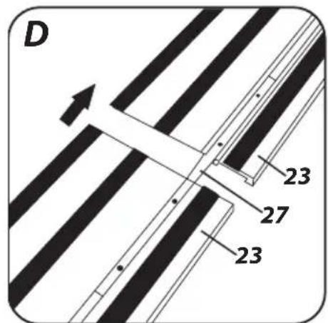
Guide rails (23) can be joined together with the connecting rod (27)
GRAPHITE
(fig. C).
- Slide half of the connecting rod (27) into the fixing groove (28) in one of the guide rails.
- Slide the other guide rail onto protruding part of the connecting rod.
- Slide the guide rails together (fig. D).
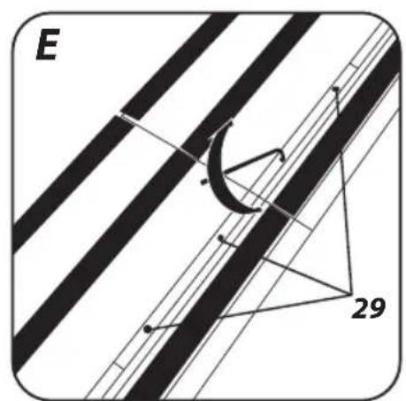
- Turn the guide rails over and align the connecting rod (27) when necessary, next tighten the pressing screws (29) (fig. E).

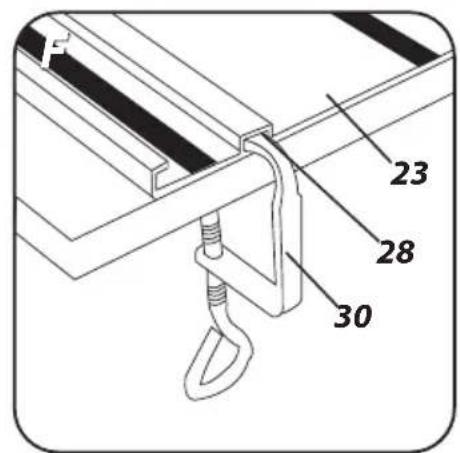
Fixing clamp can be used to attach guide rails to processed material (30) (fig. F).
- Slide the fixing clamp (30) into the fixing groove (28).
- Set the guide rail position on the processed material and position of the fixing clamp.
- Tighten the fixing clamp (30) to avoid moving of the guide rail.
- For stable position of the guide rail track, fix it with two fixing clamps (30) on two opposite sides of the track and processed material.

To guide the plunge cut track saw along the guide rail track (23), slide the saw base edge (16) into the guiding groove (31) (fig. A) in the guide rail track.
- Slide the base of the plunge cut track saw into the guide rail track.
- To allow for precise cuts, rotate eccentrically positioned adjustment knobs to negate potential slack between base (16) of the plunge cut track saw and the guide rail track (16) (fig. A).

Guide rails, connector rods and fixing clamps are not included with the device. They are available for purchase separately.
SWITCHING ON / SWITCHING OFF

The mains voltage must match the voltage on the rating plate of the plunge cut track saw. Hold the device with both hands by both handles when starting it up, because engine torque may cause uncontrolled turn of the power tool. Remember that rotating parts of the plunge cut track saw can rotate for some time after the tool has been switched off.
Switch on the plunge cut track saw only when cutting blade is away from the material that is to be cut.
Check condition of cutting blade before use of the power tool. Do not use blades with dents, cracks or other damages. Immediately replace blade that is worn out or damaged.
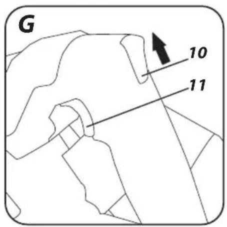
The lock button (10) serves two purposes:
• Protects the switch (11) from accidental start up.
• Prevents the cutting blade from accidental lowering.
Switching on:
- Move the lock button (10) up.
- Press the switch button (11) (fig. G).
Switching off: - Release pressure on the switch button (11) to stop the power tool.
VOLTAGE INDICATOR

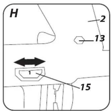
Power indicator (13) is located in the rear part of the main handle body (2). It turns on to show that the power tool is connected to mains power supply (fig. H).
ROTATIONAL SPEED CONTROL

Wheel for rotational speed control (15) is located at the bottom part of the main handle (2) (fig. H). Control range is 1 to 7. Rotational speed can be adjusted to the user's needs.
Wait a while after starting the power tool until the cutting blade reaches its top speed, only then you can proceed with your work. When working, do not use the switch of the power tool to switch it on or off. You can operate the switch only when the cutting blade has no contact with processed material.
CUTTING DEPTH ADJUSTMENT

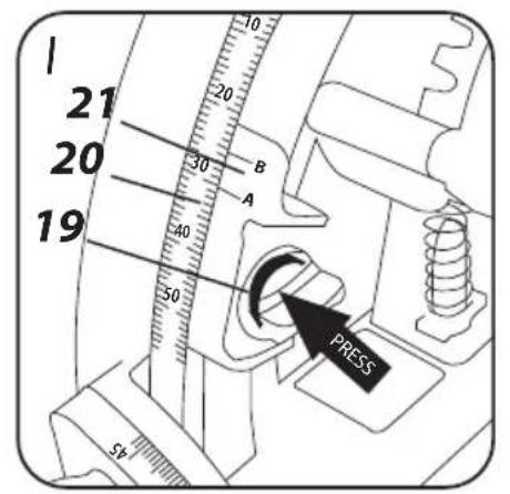
Cutting depth gauge (21) indicates cutting depth on the cutting depth scale (20).
To set up the depth, first loosen the cutting depth gauge knob (19) shown on the picture, then press it in the direction as shown on fig. I and move the gauge (smoothly, with no resistance from toothed bar) to correct position on the cutting depth scale (20). When working without guide rail track, read the cutting depth from marker A. When the guide rail track is installed, read the cutting depth from marker B of the cutting depth gauge (21). Difference in indication is 5 mm.
The toothed bar allows for quick change of the depth setting. After adjustment, tighten the cutting depth gauge knob (19).

CUTTING
Cutting line is defined by cutting line indicators (4) and (5).
To obtain the best possible cut quality, allow the cutting blade to plunge approx. 5 mm below bottom surface of the material. When setting cutting depth for material of known thickness, add 5 mm correction. In addition to setting value on the scale, it is always recommended to make a test cut or to check how the blade would plunge at the material without switching on the power tool.

Before making a cut, put the front part of the plunge cut track saw base (16) flat against the material.
- Switch on the power tool and allow the cutting blade to build up speed to maximum value.
- Hold by both handles and slowly press in (overcome the spring resistance). The cutting blade should lower towards material until it stops on the limiter, as set up on the cutting depth scale (20).
- Once the cutting blade has plunged into material, you can start cutting. Hold the cutting blade completely pressed down all the time.
- After cutting switch off the power tool and allow the cutting blade to stop completely. Then release pressure on the handle, so the cutting blade can return to its upper position.
• Take the power tool off the processed piece.

When you reduce pressure on the handle when making a cut, the cutting blade will travel upwards to its upper position as directed by the return spring. This will reduce cutting precision.
• Make cuts in straight line only.
- Do not cut material while holding it in hand.

Use only working tools with allowable rotary speed higher or equal to power tool rotary speed with no load, and diameter not greater than recommended for the power tool type.

If the object is small, fix the processed material with F-clamps. If the base of the plunge cut track saw does not move while firmly resting on the processed material, but is lifted instead, there is danger of kick back.

Properly fixed processed material and firm hold of the plunge cut track saw ensure full control over power tool operation. This allows to avoid risk of body injury. Do not try to hold short pieces of material with your hand.

MAKING A CUT BY PLUNGING INTO MATERIAL
Disconnect the saw from power supply before starting any adjustments.

When necessary, you can also start a cut in the middle of a piece. When making a plunge cut it is recommended to use the guide rail track that is fixed to the work piece in order to reduce risk of kick back to minimum.

- Loosen the cutting depth gauge knob (19).
- Set cutting depth on the scale (20)
• Tighten the cutting depth gauge knob (19).
BEVEL CUTTING

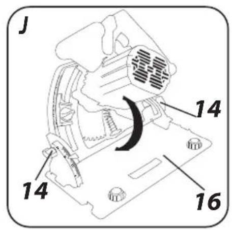
- Loosen the knobs for base position adjustment (14) (fig. J).
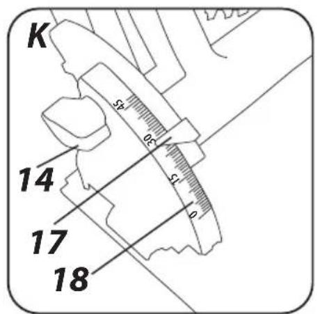
- Set the base (16) to desired angle (from 0° to 47°) using the angular scale (18) and the angle indicator (17) (fig. K).
- Tighten the knobs for base position adjustment (14).

Be aware that the risk of kick back is greater for bevel cutting (pinching of cutting blade more probable), therefore it is particularly important that the saw base rests on the processed material with its whole surface. Perform cutting with smooth move.
Unplug the power cord from mains socket before commencing any activities related to installation, adjustment, repair or maintenance.

REPLACEMENT OF WORKING TOOLS
Wear work gloves during working tool replacement.

Spindle lock button (12) is used only to lock the power tool spindle for installation or removal of working tool. It cannot be used as a brake button when the blade is rotating. Otherwise the power tool may be damaged or the user may be injured.

CUTTING BLADE REPLACEMENT
- Position the device base on the workbench top so the cutting blade sticks beyond its edge.
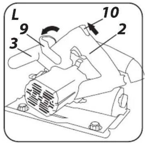
- Set the lock lever (9) forward and lift the lock button (10) (fig. L).
- Use handles (2 and 3) to apply pressure and to engage the lock immobilizing the cutting blade.
-
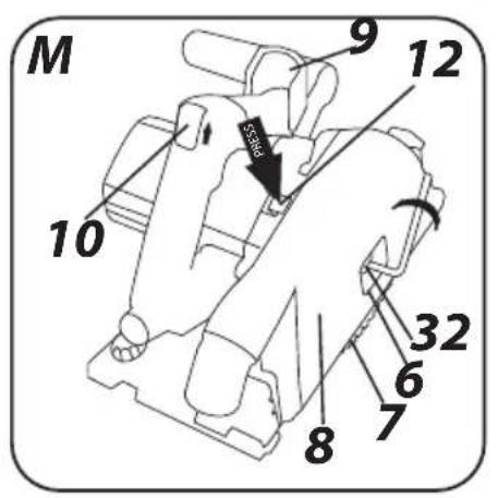
Insert hex key (included) into the head of the cutting blade fixing bolt (32), that you can see in the guard cut out (6) (fig. M).
-
Press the spindle lock button (12) and undo the fixing bolt (right hand thread). Remove outer flange.
- Slide the cutting blade (7) out through the slit in the cutting blade guard (8).
- Position new cutting blade so blade teeth and arrow on the blade match direction of the arrow on the guard.
- Slide the cutting blade into guard slot (8) and install on the spindle so it is well pressed against surface of the inner flange and centred when seated on its neck.
- Install outer flange washer, press in the spindle lock button (12) and tighten the cutting blade fixing bolt (32) by turning it clockwise.
- Set the lock lever (9) to its initial position, which will automatically shift the cutting blade to upper position.

When installing cutting blade, observe correct direction of the teeth. Arrow on the cutting blade guard shows direction of power tool spindle rotation.
MAINTENANCE AND STORAGE

- Cleaning the device after each use is recommended. - Do not use water or any other liquid for cleaning.
- Clean the device with a dry cloth or blow through with compressed air at low pressure.
- Do not use any cleaning agents or solvents, they may damage plastic parts.
- Clean ventilation holes in the motor casing regularly to prevent device overheating.
- In case of power cord damage replace it with a cord with the same specification. Entrust the repair to a qualified specialist or return the tool to a service point.
- In case of excessive commutator sparking, have the technical condition of carbon brushes of the motor checked by a qualified person.
• Always store the tool in a dry place, beyond reach of children.
Immediately replace worn out (shorter than 5 mm), burnt or cracked motor carbon brushes. Always replace both carbon brushes at a time. Entrust replacement of carbon brushes only to a qualified person. Use only original parts.

All defects should be repaired by service workshop authorized by the manufacturer.
TECHNICAL PARAMETERS
RATED PARAMETERS
| Plunge cut track saw 58G495 | |
| Parameter Value | |
| Supply voltage 230V AC | |
| Power supply frequency 50Hz | |
| Rated power 1200W | |
| Cutting blade rotational speed (no load) | 2200-5200 min^-1 |
| Outer diameter of cutting blade 165 mm | |
| Inner diameter of cutting blade 20 mm | |
| Cutting depth without guide rail track 0 ÷ 57 mm | |
| Cutting depth with guide rail track 0 ÷ 52 mm | |
| Bevel cutting range 0^ ÷ 47^ | |
| Protection class II | |
| Weight 4,6 kg | |
| Year of production 2021 | |
| 58G495 defines type and indication of the device | |
NOISE LEVEL AND VIBRATION PARAMETERS
| Sound pressure | Lp_A = 90,73 dB(A) K = 3 dB(A) |
| Sound power | Lw_A = 101,73 dB(A) K = 3 dB(A) |
| Value of vibration acceleration, primary handle | a_h = 3,249 m/s^2 K = 1,5 m/s^2 |
| Value of vibration acceleration, auxiliary handle | a_h = 2,828 m/s^2 K = 1,5 m/s^2 |
Noise and vibration information
Noise produced by the device is defined with: level of produced sound pressure Lp_A and level of sound power Lw_A (where K is measurement
uncertainty). Vibrations produced by the device are defined with vibration acceleration value ah (where K is measurement uncertainty). Sound pressure Lp_A , sound power Lw_A and vibration acceleration ah specified in this manual have been measured in accordance with EN 60745-1:2009+A11. Specified vibration level ah can be used to compare tools and for initial evaluation of exposition to vibrations.
Specified vibration level is representative for main applications of the device. When the device is used for other purposes or with different working tools, the vibration level may change. Insufficient or too rare maintenance may increase vibration level. The abovementioned factors may lead to higher exposure to vibrations during whole working time.
To precisely define exposure to vibrations, include periods when the device is switched off and when it is switched on but not used for working. Once all factors have been carefully considered, total exposition to vibrations may be significantly lower.
To protect the user from results of exposure to vibrations, use additional safety measures such as: device and working tool periodic maintenance, proper hand temperature conditions, good work organisation.
ENVIRONMENTAL PROTECTION
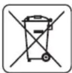
Electrical equipment must not be disposed off with household waste and, instead, should be utilized at appropriate facilities. Information on utilization can be provided by the product vendor or the local authorities. Waste electrical and electronic equipment contains substances that are not neutral to the natural environment. Equipment that is not recycled constitutes a potential hazard to the environment and to human health.
* Right to introduce changes is reserved.
"Grupa Topex Spółka z ograniczoną odpowiedzialności" Spółka komandytowa with seat in Warsaw at ul. Pograniczna 2/4 (hereinafter Grupa Topex) informs, that all copyrights to this instruction (hereinafter Instruction), including, but not limited to, text, photographs, schemes, drawings and layout of the instruction, belong to Grupa Topex exclusively and are protected by laws accordingly to Copyright and Related Rights Act of 4 February 2004 (ustawa o prawie autorskim i prawach pokrewnych, Dz. U. 2006 No 90 item 631 with later amendments). Copying, processing, publishing, modifications for commercial purposes of the entire Instruction or its parts without written permission of Grupa Topex are strictly forbidden and may cause civil and legal liability.
GRAFISKÄS DALAS APRAKSTS
POSEBNI PROPISI O SIGURNOSTI
DETALJNE SIGURNOSNE NAPOMENE VEZANE ZA KORISTENJE KRUŽNIH UBODNIH PILA BEZ RAZVODNOG KLINA
a. OPASNOST: Ruke držite podalje od radne zone i od lista pile. Drugu ruku držite na pomoćnoj dršci ili na kućištu motora. Ako pilu držite s obje ruke, smanjuje se opasnost od nastanka ozljeda uzrokovanih listom pile.
b. Ruke nemojte stavljati ispod obrađivanog predmeta. Štitnik ne može učinkovito zaštićivati od rotirajućeg lista pile ispod izratka.
c. Postavite dubinu rezanja adekvatnu do dubine izratka. Preporuča se da list pile strši ispod rezanog materijala manje nego do visine zuba.
AFVOEREN VAN HET STOF

- INSTRUKCJA ORYGINALNA (OBSŁUGI) PILARKO - ZAGŁĘBIARKA 58G495
- SZCZEGÓŁOWE PRZEPISY BEZPIECZEŃSTWA
- SZCZEGÓŁOWE BEZPIECZEŃSTWO UŻYTKOWANIA PILAREK TARCZOWYCH WRZYNAJĄCYCH BEZ KLINA ROZSZCZEPIAJĄCEGO
- TRANSLATION OF THE ORIGINAL INSTRUCTIONS
- PLUNGE CUT TRACK SAW
- 58G495
- DETAILED SAFETY REGULATIONS
- Cutting procedures
- Additional safety instructions
- Safe work and maintenance
- CAUTION! This device is designed to operate indoors.
- CONSTRUCTION AND USE
- DESCRIPTION OF DRAWING PAGES
- MEANING OF SYMBOLS
- EQUIPMENT AND ACCESSORIES
- USE OF THE GUIDE RAIL TRACK
- GRAPHITE
- (fig. C).
- SWITCHING ON / SWITCHING OFF
- VOLTAGE INDICATOR
- ROTATIONAL SPEED CONTROL
- CUTTING DEPTH ADJUSTMENT
- CUTTING
- MAKING A CUT BY PLUNGING INTO MATERIAL
- BEVEL CUTTING
- REPLACEMENT OF WORKING TOOLS
- CUTTING BLADE REPLACEMENT
- MAINTENANCE AND STORAGE
- TECHNICAL PARAMETERS
- Noise and vibration information
- ENVIRONMENTAL PROTECTION
- GRAFISKÄS DALAS APRAKSTS
- POSEBNI PROPISI O SIGURNOSTI
- AFVOEREN VAN HET STOF
Brand : Graphite
Model : 58G495
Category : Saw