
TSA 230 - Grinder STIHL - Free user manual and instructions
Find the device manual for free TSA 230 STIHL in PDF.


| Product Type | Cordless Cut-Off Machine (Grinder) |
| Model | STIHL TSA 230 |
| Battery Type | Lithium-Ion, STIHL AP Series |
| Max Spindle Speed | 6650 rpm |
| Abrasive Wheel Diameter | 230 mm (9") |
| Max Wheel Thickness | 3 mm |
| Bore Diameter | 22.23 mm (7/8") |
| Tightening Torque | 20 Nm (177 lbf·in) |
| Max Depth of Cut | 70 mm (2.756 in) |
| Weight (without battery & wheel) | 3.9 kg (8.6 lbs) |
| Water Supply Max Pressure | 4 bar (58 psi) |
| Sound Pressure Level (cutting concrete) | 103 dB(A) |
| Sound Power Level | 114 dB(A) |
| Vibration Level (left handle) | 3.5 m/s² |
| Compatible Chargers | STIHL AL 100, AL 300, AL 500 |
| Power Source | Cordless, Battery-Powered |
| Cutting Modes | Wet and Dry Cutting |
| Guard Type | Adjustable Abrasive Wheel Guard |
| Locking Lever | Yes, prevents accidental start |
| Spindle Lock | Yes, for wheel changes |
| Water Attachment | Integrated, with shut-off valve |
Frequently Asked Questions - TSA 230 STIHL
User questions about TSA 230 STIHL
0 question about this device. Answer the ones you know or ask your own.
Ask a new question about this device
Download the instructions for your Grinder in PDF format for free! Find your manual TSA 230 - STIHL and take your electronic device back in hand. On this page are published all the documents necessary for the use of your device. TSA 230 by STIHL.
USER MANUAL TSA 230 STIHL
natural_image
White STIHL T5A 230 power saw cutting tool with visible blade and handle (no text or symbols on device body)2 - 34 Gebrauchsanleitung
34 - 65 Instruction Manual
65 - 98 Manual de instrucciones
98 - 127 Skötselanvisning
127 - 157 Käyttöohje
157 - 187 Betjeningsvejledning
187 - 217 Bruksanvisning
217 - 249 Návod k použití
249 - 281 Használati utasítás
281 - 315 Instruções de serviço
315 - 352 Инструкция по эксплуатации
352 - 386 Instrukcja użytkowania
386 - 424 Ръководство за употреба
424 - 457 Instructiuni de utilizare


Inhaltsverzeichnis
natural_image
Line drawing of hands using a STIHL TSA 230 power cutter on a cutting board (no text or symbols on the diagram itself)natural_image
Illustration of a hand using a STIHL TSA 23D tool to cut a circular component (no text or symbols on the diagram itself)natural_image
Technical line drawing of a cylindrical mechanical component embedded in a textured surface, with no visible text or symbols.natural_image
Technical illustration of a mechanical tool cutting a circular component (no text or symbols)natural_image
Technical illustration of a hand using a tool to cut a circular component (no text or symbols present)natural_image
Technical line drawing of a saw cutting process with a circular cutter (no text or symbols)natural_image
Technical line drawing of a mechanical tool cutting a circular component, with no visible text or symbolsnatural_image
Illustration of hands using a tool to cut a circular component, no text or symbols presentnatural_image
Technical line drawing of a mechanical component with a circular end and two protruding pins (no text or symbols)1 Guide to Using this Manual....34
2 Safety Precautions....35
3 Reactive Forces.... 40
4 Working Techniques.... 41
5 Sample Applications.... 42
6 Cutting Wheels....46
7 Composite Abrasive Wheels......46
8 Diamond Abrasive Wheels....46
9 Mounting an Abrasive Wheel.... 48
10 Connecting Charger to Power Supply.....50
11 Charging the Battery.... 50
12 LEDs on Battery....51
13 LED on Charger.... 53
14 Connecting the water supply....53
15 Switching On....54
16 Switching Off....55
17 Storing the Machine.... 55
18 Maintenance and Care....56
19 Minimize Wear and Avoid Damage....56
20 Main Parts....57
21 Specifications....58
22 Troubleshooting.... 59
23 Maintenance and Repairs.... 60
24 Disposal.... 60
25 EC Declaration of Conformity.... 61
26 UKCA Declaration of Conformity.... 61
27 General Power Tool Safety Warnings......62
Dear Customer,
Thank you for choosing a quality engineered STIHL product.
It has been built using modern production techniques and comprehensive quality assurance.
Every effort has been made to ensure your satisfaction and trouble-free use of the product.
Please contact your dealer or our sales company if you have any queries concerning this product.
Your
Dr. Nikolas Stihl
1 Guide to Using this Manual
This Instruction Manual refers to a STIHL cordless cut-off machine, also called power tool or machine in this Instruction Manual.
1.1 Pictograms
All the pictograms attached to the machine are shown and explained in this manual.
1.2 Symbols in text

WARNING
Warning where there is a risk of an accident or personal injury or serious damage to property.
NOTICE
Caution where there is a risk of damaging the machine or its individual components.
1.3 Engineering improvements
STIHL's philosophy is to continually improve all of its products. For this reason we may modify the design, engineering and appearance of our products periodically.
Therefore, some changes, modifications and improvements may not be covered in this manual.
2 Safety Precautions

Special safety precautions must be taken when working with the cut-off machine, due to the very high rotational speed of the abrasive wheel.

It is important you read and understand the Instruction Manual before first use and keep the manual in a safe place for future reference. Non-observance of the safety instructions may result in serious or even fatal injury.
2.1 General compliance
Comply with national safety regulations issued, e.g. by employers' liability insurance associations, social security institutions, occupational safety and health authorities or other organizations.
As for employers within the European Community, the provision 2009/104/EC is binding – Safety and health protection with the use of machines and devices by employees at work
The use of noise emitting power tools may be restricted to certain times by national or local regulations.
If you have not used this cut-off machine model before: Have your dealer or other experienced user show you how to operate your machine – or attend a special course in its operation.
Minors should never be allowed to use the cut-off machine – except for young trainees over the age of 16 when working under supervision.
Children, animals and bystanders must remain at a distance.
The user is responsible for avoiding injury to third parties or damage to their property.
The cut-off machine should only be provided or loaned to people familiar with this model and its operation. The instruction manual should always be handed over with the machine.
Anyone operating the cut-off machine must be well rested, in good health and in good physical shape. If you have any condition that might be aggravated by strenuous work, check with your doctor before operating a cut-off machine.
Anyone who has consumed alcohol, medicines affecting their ability to react or drugs must not operate the cut-off machine.
Postpone the work if the weather is bad (rain, snow, ice, wind) – higher risk of accidents!
Remove the battery from the cut-off machine before:
- Carrying out tests and adjustments or cleaning work
- Fitting or changing the abrasive wheel
- Mounting and removing accessories, configuring settings
– Leaving the cut-off machine unattended - Transport
- Storage
- Performing repairs and maintenance work
– In the event of danger or in an emergency
This avoids the risk of the engine starting unintentionally.
2.2 Intended use
The cut-off machine may only be used for cutting. It is not suitable for cutting wood or wooden objects.
Do not use the cut-off machine for any other purpose – risk of accidents!
Asbestos dust is extremely toxic - the machine must therefore never be used to cut asbestos!
STIHL recommends operating the cut-off machine with STIHL batteries type AP.
For work that is not carried out on the ground, only operate the cut-off machine with STIHL batteries type AP placed directly in the machine.
Do not modify the cut-off machine in any way – this may increase the risk of personal injury. STIHL excludes all liability for personal injury and damage to property caused while using unauthorized attachments.
2.3 Clothing and equipment
Wear proper protective clothing and equipment.
Clothing must be sturdy but allow complete freedom of movement. Wear close-fitting clothes such as a boiler suit, not a work coat.
When cutting steel, always wear clothing made of hard-to-ignite material (e.g., leather, or cotton with flame-retardant finish) – no man-made fibers – risk of fire due to flying sparks!
Clothing must be free from flammable deposits (chips, fuel, oil, etc.).
Do not wear clothes that may be caught by moving parts – no scarf, no tie, no jewelry. Tie long hair back securely.

Wear steel-toed safety boots with non-slip soles.

WARNING

To reduce the risk of eye injuries, wear close-fitting safety glasses in accordance with European Standard EN 166. Make sure the safety glasses are a snug fit.
Wear "personal" sound protection, e.g. ear defenders.
Wear a safety hard hat where there is a danger of head injuries from falling objects.
Dust (e. □g., crystalline material from the object being cut), fumes and smoke may be produced while cutting - health hazard!
Always wear a dust mask if dust is generated.
If fumes or smoke are anticipated (e. g., when cutting composite materials), wear respiratory protection.

Wear sturdy protective gloves made of a resistant material (e. g. leather).
STIHL can supply a comprehensive range of personal protective equipment.
Check the condition of the equipment before each use and replace any damaged parts.
2.4 Transport
Before transport – even over shorter distances – always switch off the machine, set the locking lever to 🔒 and remove the battery from the cut-off machine. This avoids the risk of the engine starting unintentionally.
Allow the cut-off machine or battery to dry out separately if they are wet after use. During transport, make sure that the cut-off machine and battery remain dry. Only transport the battery in clean and dry containers, do not use metallic transport containers.
Remove the battery before transporting the cut-off machine.
Carry the cut-off machine only by the handle – abrasive wheel pointing backwards.
Never transport the cut-off machine with attached abrasive wheel – risk of breakage!
In vehicles: Properly secure the cut-off machine to prevent turnover and damage.
2.5 Cleaning
Clean plastic parts with a cloth. Harsh detergents can damage the plastic.
Clean the cut-off machine to remove dust and dirt – do not use degreasing agents.
Clean the ventilation slots if necessary.
Extract metal chips – do not blow off with compressed air.
Keep the guide grooves of the battery free of dirt – clean if necessary.
Do not use high-pressure cleaners to clean the cut-off machine. The hard water jet can damage parts of the cut-off machine.
Do not spray the cut-off machine with water.
2.6 Accessories
Only use abrasive wheels or accessories which have been approved by STIHL for this cut-off machine or which are technically equivalent. If you have any questions in this respect, consult a servicing dealer. Only use high-quality abrasive wheels and attachments. Otherwise there may be a risk of accidents or damage to the cut-off machine.
STIHL recommends the use of genuine STIHL abrasive wheels and accessories. They are specifically designed to match your model and meet your performance requirements.

Never use circular saw blades, carbide, rescue or wood cutting attachments or saws of any kind – these may cause fatal injuries! Instead of uniformly removing particles as when cutting with an abrasive wheel, the teeth of a circular saw blade may snag in the material. This causes the cut-off machine to react in a highly aggressive manner with uncontrolled and extremely dangerous kickback.
2.6.1 Depth stop with suction support
The "depth stop with suction support" is available as a special accessory and can be used when dry cutting mineral material. Observe the supple-
2 Safety Precautions English
ment sheet supplied with the special accessory and keep in a safe place.
When dry cutting mineral material, the stress from dust produced can be reduced by the "depth stop with suction support" in conjunction with dust extraction.
Always wear a dust mask if dust is generated.
If fumes or smoke are anticipated (e. g., when cutting composite materials), wear respiratory protection.
The dust extraction used must be approved for suctioning mineral material and must correspond to dust class M.
To prevent electrostatic effects, use an antistatic suction hose. Otherwise there is the risk of loss of control!
To dispose of the material collected, refer to the Instruction Manual for the dust extractor.
The desired cutting depth can be set via the "depth stop with suction support".
2.7 Drive
2.7.1 Battery
Observe the supplement sheet or instruction manual for the STIHL battery and keep in a safe place.
Further safety instructions – see www.stihl.com/safety-data-sheets
Protect STIHL batteries and the STIHL battery belt from flying sparks when cutting steel – risk of fire or explosions!
Keep STIHL batteries away from dirty water (e. g. from additives or solid matter), conductive liquids and metal objects (e. g. nails, coins, jewellery, metal chips). The batteries can be damaged – risk of fire or explosions!
Battery charger
Observe the supplement sheet for the STIHL charger and keep in a safe place.
2.8 Cut-off machine, spindle bearing
Correct spindle bearings ensure the concentricity and axial running of the diamond abrasive cutting wheel – if necessary, get it checked by an approved dealer.
2.9 Abrasive cutting wheels
2.9.1 Selecting the abrasive cutting wheels
Abrasive cutting wheels must be approved for freehand cutting. Do not use other abrasive units and attachments – risk of accident!
Abrasive cutting wheels are suitable for different materials: Observe the identification of the abrasive cutting wheels.
STIHL generally recommends wet cutting.
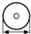
Observe the outside diameter of the abrasive cutting wheel – refer to the chapter "Specifications".
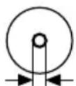
Spindle hole diameter of the abrasive cutting wheel and shaft of the cut-off machine must match – refer to the chapter "Specifications".
Check the spindle hole for damage. Do not use abrasive cutting wheels with a damaged spindle hole – risk of accident!

The permissible speed of the abrasive cutting wheel must be equal to or greater than the maximum spindle speed of the cut-off machine. – Refer to the chapter "Specifications".
Before fitting a used abrasive cutting wheel, check that it is not cracked, chipped, undercut or uneven, and does not display any signs of core fatigue or overheating (discoloration); check also that there are no damaged or missing segments and that the spindle hole is not damaged.
Never use cracked, chipped or bent abrasive cutting wheels.
Substandard and/or unapproved diamond abrasive cutting wheels can shimmy during cutting. This shimmying can cause such diamond abrasive cutting wheels to be abruptly braked or become stuck in the cut – Danger of kickback! Kickback can result in fatal injuries! Diamond abrasive cutting wheels that shimmy constantly or even only intermittently must be replaced immediately.
Never straighten diamond abrasive cutting wheels.
Do not use an abrasive cutting wheel which has fallen to the ground – damaged abrasive cutting wheels may break – risk of accident!
Observe the expiration date where resin abrasive cutting wheels are concerned.
English 2 Safety Precautions
2.9.2 Fitting abrasive cutting wheels
Inspect the spindle of the cut-off machine. Do not use a cut-off machine if the spindle is damaged – risk of accident!
Note the arrows indicating the direction of rotation on diamond abrasive cutting wheels.
Position the front pressure plate – tighten up the clamping screw – rotate the abrasive cutting wheel by hand and take a sight check for concentricity and axial running.
2.9.3 Storing abrasive cutting wheels
Store abrasive cutting wheels in a dry and frost-free place, on a flat surface, at constant temperature – risk of breakage and splintering!
Always protect the abrasive cutting wheel against sudden contact with the ground or objects.
2.10 Before starting work
Inspect the parting-off grinder for safe-to-operate state – observe the respective chapters in the instruction manual:
- Trigger switch and trigger switch lockout must move easily – trigger switch and trigger switch lockout must return to initial position when released
- The abrasive wheel must be suitable for the material to be cut. It must be in good condition and fitted correctly (direction of rotation, secure).
- Trigger switch is locked when the trigger switch lockout is not depressed
- Locking lever easy to set to 📋 or 🔊
- Never attempt to modify the controls or safety devices in any way
- Keep the handles clean, dry and free of oil as well as dirt – important for safe guiding of the parting-off grinder.
- Check contacts in the battery compartment of the cut-off machine for foreign matter and dirt
- Fit the battery correctly – it must engage audibly
- Do not use defective or deformed batteries
- For wet applications, provide sufficient water
The cut-off machine should only be used if it is in full working order – risk of accident!
2.11 Switching on the machine
On even ground, ensure a firm and secure footing and hold the cut-off machine firmly – the abrasive wheel must not touch any objects or the ground and must not be in cutting action.
The cut-off machine is a one-person unit. Do not allow other persons to be near the machine.
Switch on as described in the Instruction Manual – see "Switching on the machine".
After releasing the trigger switch, the abrasive wheel keeps on running for a while – danger of injury due to coasting effect!
2.12 During operation
Use the cut-off machine only for hand-held cutting.
Ensure you always have a firm and secure footing.
natural_image
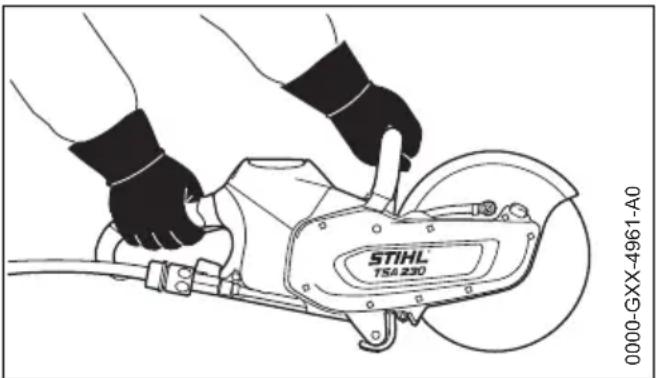
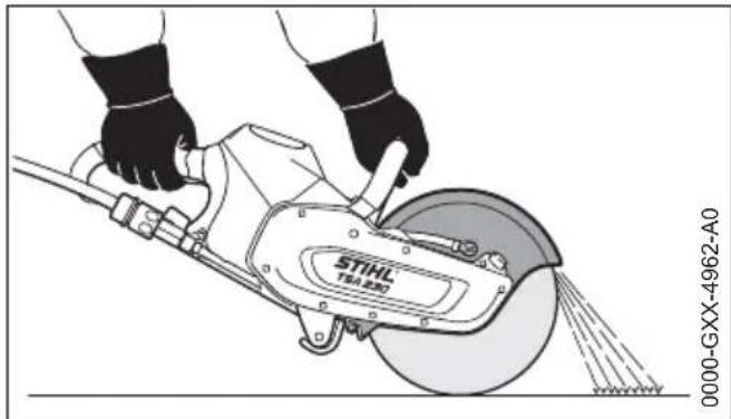
Line drawing of hands operating a STIHL TSA 230 cutting tool (no text or symbols on the diagram itself)Always hold the cut-off machine firmly with both hands: Right hand on the rear handle – even if you are left-handed. To ensure reliable control, wrap your thumbs tightly around the handlebar and handle.
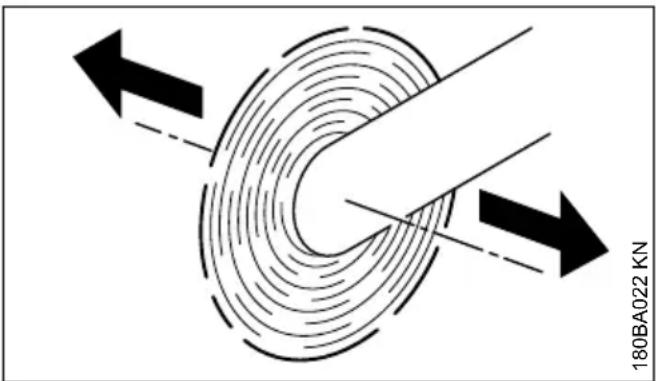
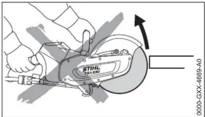
When a cut-off machine with an abrasive cutting wheel rotating is moved in the direction of the arrow, a force is produced which causes the machine to tip sideways.
The object to be parted-off has to be firmly supported. Always guide the cut-off machine towards the workpiece – never in reverse.
natural_image
Illustration of a hand using a STIHL TSA 23D tool to cut a circular component, no text or symbols present.Set the abrasive cutting wheel guard so that particles of material are guided away from the user and cut-off machine.
Note the direction of travel of the abraded particles of material.
In case of imminent danger or in an emergency, switch off the machine immediately, move the locking lever to ☐ and remove the battery.
Keep the working area clear – bear in mind obstacles, holes and pits.
This cut-off machine can be used for work in the rain or wet. Allow the cut-off machine or battery to dry out separately if they are wet after use.
Do not leave the cut-off machine outdoors in the rain.
Take care on ice, water, snow, on slopes or uneven ground, etc. – risk of slipping!
Never work alone – always stay in earshot of other persons who can help in an emergency.
Pay increased attention and take greater care when wearing ear defenders – the perception of sounds indicating potential danger (shouts, audible warnings, etc.) is restricted.
Take a break in good time to avoid tiredness or exhaustion – risk of accidents!
Keep everyone else away from the working area – maintain a sufficient distance from other people to protect them from noise and flying objects.
If you feel sick, if you have a headache, vision problems (e. g., your field of vision gets smaller), hearing problems, dizziness or inability to concentrate, stop work immediately – risk of accident!
If the cut-off machine has been exposed to stress due to improper use (for example, impact of force by blow or crash), test the device for safe-to-operate condition before continuing work, in every case – see also "Before start-up". Make
sure the safety devices are working properly. Do not continue operating the cut-off machine if damaged. In case of doubt, have the unit checked by your servicing dealer.
Never touch a rotating abrasive cutting wheel with your hand or any other part of your body.
Check the work area. Avoid danger due to damage to pipes and electric power lines.
The cut-off machine must not be used in the vicinity of flammable substances and combustible gases.
Do not cut into pipes, metal tanks or other containers unless you are absolutely sure that they do not contain any volatile or flammable substances.
Before placing the cut-off machine on the ground and leaving the cut-off machine unattended:
- Switch off the machine
- Set locking lever to 🔒
- Wait until the abrasive cutting wheel has come to a standstill or brake the abrasive cutting wheel until it comes to a standstill by carefully touching a hard surface (e.g., concrete slab)
- Remove the battery. If the battery is removed whilst the abrasive cutting wheel is running, this extends the coasting effect – risk of injury!

Frequently inspect the abrasive cutting wheel – replace it right away if there are visible cracks, buckling or other damage (for example, overheating) – risk of accident due to breakage!
In the event of changes in cutting behavior (e.g., increased vibration, reduced cutting performance), stop work and eliminate the causes of the changes.
An abrasive cutting wheel can become hot during dry cutting. Never touch the stationary abrasive cutting wheel – risk of burns!
2.13 After finishing work
Turn off machine, set the locking lever to 🔒 and remove the battery from the cut-off machine.
NOTICE
If the battery is not removed, there is the risk that the plug-in contacts on the cut-off machine and battery become corroded. Such corrosion can cause irreparable damage to the cut-off machine and battery.
Allow the cut-off machine or battery to dry out separately if they are wet after use.
2.14 Storage
When the cut-off machine is not in use it should be parked in such a way that no-one is endangered. Ensure that the cut-off machine cannot be used without authorization.
The cut-off machine must be stored in a dry room with the locking lever set to ☐ and only with the battery removed.
NOTICE
If the battery is not removed, there is the risk that the plug-in contacts on the cut-off machine and battery become corroded. Such corrosion can cause irreparable damage to the cut-off machine and battery.
Allow the cut-off machine or battery to dry out separately if they are wet after use.
2.15 Vibrations
Prolonged use of the power tool may result in vibration-induced circulation problems in the hands (whitefinger disease).
No general recommendation can be given for the length of usage because it depends on several factors.
The period of usage is prolonged by:
- Hand protection (wearing warm gloves)
- Work breaks
The period of usage is shortened by:
- Any personal tendency to suffer from poor circulation (symptoms: frequently cold fingers, tingling sensations).
– Low outside temperatures. - The force with which the handles are held (a tight grip restricts circulation).
Continual and regular users should monitor closely the condition of their hands and fingers. If any of the above symptoms appear (e.g. tingling sensation in fingers), seek medical advice.
2.16 Maintenance and repairs
Before all repair and maintenance work, always switch off the machine, set the locking lever to ⏻ and remove the battery from the cut-off machine. If the abrasive wheel starts inadvertently – risk of injury!
The cut-off machine must be serviced regularly. Do not attempt any maintenance or repair work not described in the Instruction Manual. All other work should be carried out by a servicing dealer.
STIHL recommends that maintenance and repair work be carried out only by authorized STIHL dealers. STIHL dealers receive regular training and are supplied with technical information.
Use only high-quality spare parts. Otherwise, there may be a risk of accidents and damage to the cut-off machine. If you have any questions in this respect, consult a servicing dealer.
STIHL recommends the use of genuine STIHL spare parts. They are specifically designed to match your cut-off machine and meet your performance requirements.
Do not modify the cut-off machine in any way – this can be extremely dangerous –risk of accidents!
Check existing electrical contacts, power cords and power plug of the charger regularly for undamaged insulation and aging (brittleness).
Electrical components, e.g., the power cord of the charger, may only be repaired and/or replaced by qualified electricians.
3 Reactive Forces
The most frequently occurring reactive forces are kickback and pull-in.
3.1 Kickback
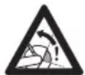
Danger of kickback – Kickback can result in fatal injuries.
4 Working Techniques English
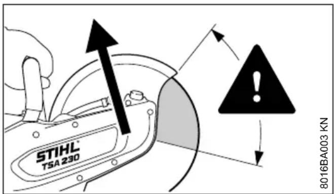
Kickback occurs when the cut-off machine is suddenly thrown up and back in an uncontrolled arc towards the operator.
Kickback occurs if, for example, the abrasive cutting wheel
- gets jammed - especially the upper quarter, or
- is abruptly braked through friction contact with a solid object
Reducing the risk of kickback
- Work cautiously and methodically
- Hold the cut-off machine firmly with both hands and maintain a secure grip
- If possible, avoid using the upper quarter of the abrasive cutting wheel for cutting. Use extreme caution when guiding the abrasive cutting wheel into a cut, do not twist or push into the cut
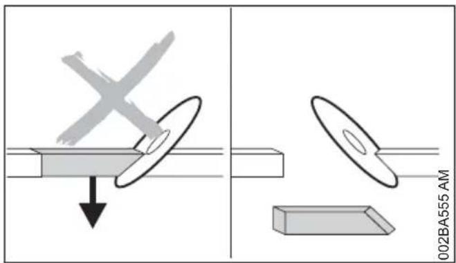
- Avoid any wedge effect - the severed part must not brake the abrasive cutting wheel
- Always be aware that the object to be cut may move and other factors may cause the cut to close and jam the abrasive cutting wheel.
- The object to be cut must be secured and supported so that the kerf remains open during and after cutting
- Objects to be cut must therefore be fully supported and must be secured against rolling away, slipping off or vibrations
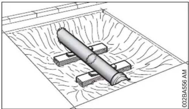
natural_image
Technical line drawing of a mechanical assembly with cylindrical components embedded in a textured rectangular base (no text or symbols)- An exposed pipe must be provided with a stable support that will bear its weight, using wedges if necessary – always bear in mind a proper support and the nature of the ground – material may crumble away
- Always work with water and wet cutting when using diamond abrasive cutting wheels
- Depending on the version, resin abrasive cutting wheels are suitable only for dry cutting or only for wet cutting. Always use wet cutting with composite resin abrasive cutting wheels that are suitable only for wet cutting
3.2 Pulling away
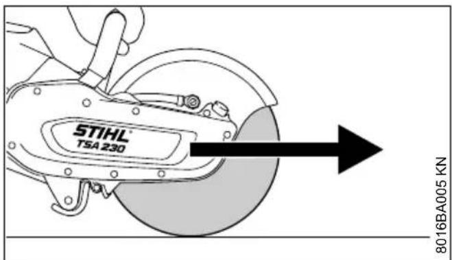
The cut-off machine pulls forward, away from the user, when the abrasive cutting wheel touches the object to be cut from above.
4 Working Techniques
4.1 Cutting
Work calmly and carefully – in daylight conditions and only when visibility is good. Do not endanger others – stay alert at all times.

The abrasive wheel must be guided straight in the cut, without wedging. Never exert lateral pressure on the abrasive wheel.

Do not use for lateral grinding or scrubbing.
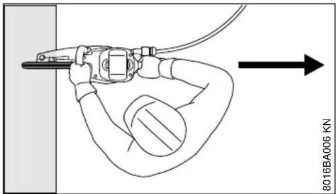
Do not stand in line with the abrasive wheel. Ensure sufficient freedom of movement, especially in construction trenches there must be sufficient space for the user and for the part being cut to fall.
Do not lean too far forwards and never bend over the abrasive wheel.
Don not work while standing on a ladder – not at unstable places – not over your shoulder height – not with one hand only – risk of accident!
The cut-off machine may only be used for cutting. It must not be used as a lever or shovel.
Do not press down on the cut-off machine
Always decide the cutting direction before positioning the cut-off machine. Do not change the cutting direction. Avoid knocks and bumps with the cut-off machine while in the cut – do not drop the machine into the cut – danger of breakage!
Diamond abrasive wheels: If cutting performance begins to deteriorate, check the sharpness of the diamond abrasive wheel, resharpen as needed. To do this, briefly cut through abrasive material, e. g., sandstone, aerated concrete or asphalt.
At the end of the cut, the cut-off machine is no longer supported by the abrasive wheel in the cut. The user has to absorb the weight force – risk of loss of control!
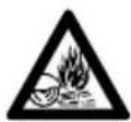
When cutting steel: glowing metal particles may cause fires!
Keep water and sludge away from alive electrical cables – risk of electric shock!
Drag the abrasive wheel into the workpiece – do not push it into the material. Do not correct severing cuts with the cut-off machine. Do not recut – remove left webs or breaking edges (for example, with a hammer).
When applying diamond-coated abrasive wheels, take a wet cut.
Depending on the version, resin abrasive wheels are only suitable for dry cutting or only for wet cutting.
When using abrasive wheels made from synthetic resin, which are suited for wet cuts only, take such wet cuts only.
When using abrasive wheels made from synthetic resin, which are suited for dry cuts only, take such dry cuts only. If however composite resin abrasive wheels of this type become wet, their cutting performance is reduced and they become dull. If composite resin abrasive wheels of this type become wet while working (e.g., due to puddles or water in pipes), do not increase the cutting pressure, but continue working with the same pressure – risk of breakage! Use up such composite resin abrasive wheels immediately.
5 Sample Applications
5.1 Water attachment
– Water attachment on the cut-off machine for all types of water supplies
- Pressurized water tank 10 l for binding dust
Use clean water for binding dust.
5.2 Water must always be used for wet cutting when working with diamond abrasive cutting wheels
5.2.1 Extend service life and increase cutting speed
Always ensure a supply of water to the abrasive cutting wheel.
5.2.2 Binding dust
The abrasive cutting wheel must be supplied with at least 0.6 liters of water per minute.
5.3 Use composite resin abrasive cutting wheels with or without water – depending on version
Depending on the version, resin abrasive cutting wheels are suitable only for dry cutting or only for wet cutting.
5.3.1 Composite resin abrasive cutting wheels suitable only for dry cutting
During dry cutting, wear a suitable dust mask.
5 Sample Applications English
If fumes or smoke are anticipated (e.g., when cutting composite materials), wear respiratory protection.
5.3.2 Composite resin abrasive cutting
wheels suitable only for wet cutting
Use abrasive cutting wheel only with water.

To bind dust, the abrasive cutting wheel must be supplied with at least 1 liter of water per minute. To avoid a reduction in cutting performance, the abrasive cutting wheel must be supplied with not more than 4 liters of water per minute.
After using the abrasive cutting wheel, the wheel should be allowed to continue spinning at operating speed for approx. 3 to 6 seconds without water in order to spin off the water remaining on it.
5.4 Observe with diamond and composite resin abrasive cutting wheels
5.4.1 Objects to be cut
- Must be fully supported
- Must be secured so they cannot roll or slip off
- Must be prevented from vibrating
5.4.2 Severed parts
With openings, recesses, etc., the sequence of the cuts is important. Always make the last cut so that the abrasive cutting wheel does not become jammed and so that the operator is not endangered by the severed or separated part.
If necessary, leave small ridges that hold the part that is to be separated in position. Break these ridges later.
Before finally separating the part, determine:
- how heavy the part is
– how it can move after separation - whether it is under tension
When breaking out the part, do not endanger assistants.
5.5 Cut in several passes
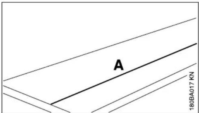
▶ Mark cutting line (A)
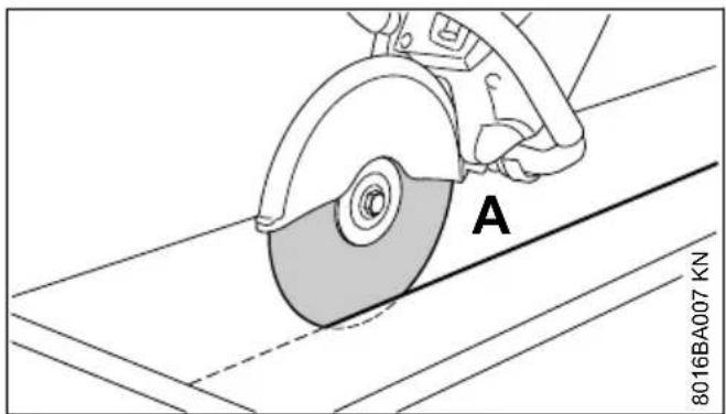
▶ Work along the cutting line. When making corrections, do not tilt the abrasive cutting wheel, but always set the abrasive cutting wheel against the workpiece anew – the cutting depth for each operation should not exceed 2 cm. Cut thicker material in multiple passes
5.6 Cutting plates
- Secure the plate (e. g. on a non-slip surface, sandbed)
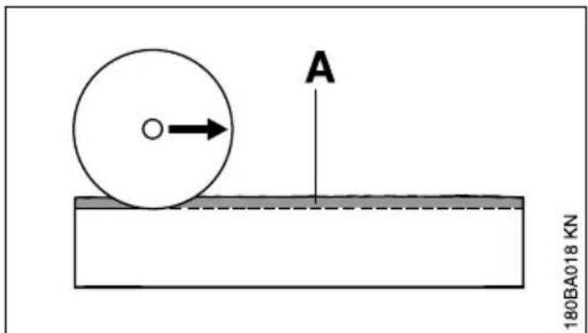
▶ Cut a guide groove (A) along the line marked
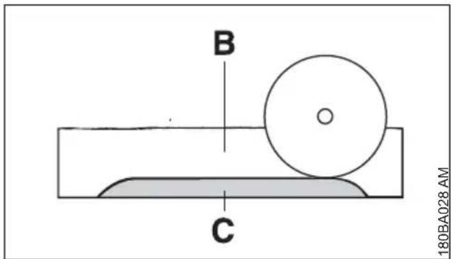
▶ Make the cut (B) deeper
Leave a "hinge" (C)
▶ First sever the plate at the cut ends so that no material breaks away
▶ Break plate
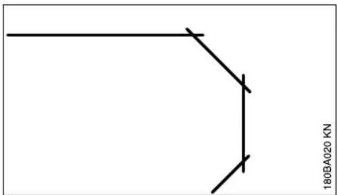
- Make curves in multiple passes – make certain that the abrasive cutting wheel does not tilt
5.7 Cutting pipes, round and hollow bodies
- Secure pipes, round and hollow bodies against vibrations, slipping and rolling away
- Note direction of fall and weight of the severed part
▶ Determine and mark the cutting line, avoid reinforcements, especially in the direction of the severing cut
▶ Determine sequence of severing cuts
▶ Cut a guide groove along the line marked
▶ Make cut deeper along the guide groove – observe the recommended cutting depth for each operation – for small corrections of direction, do not tilt the abrasive cutting wheel, but always position it anew instead – if necessary, leave small ridges that hold the part that is to be separated in position. Break these ridges after the last planned cut
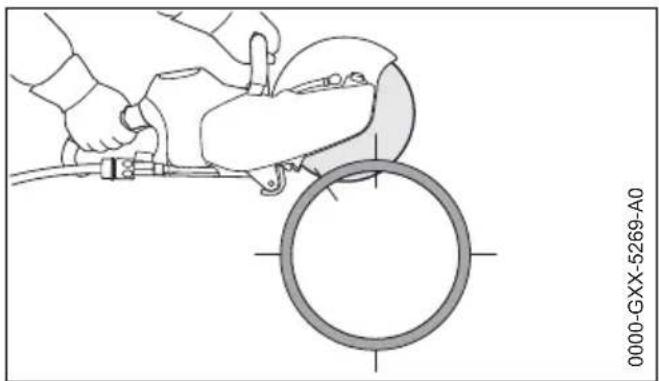
5.8 Cutting concrete pipe

The procedure is dependent on the outer diameter of the pipe and the maximum possible cutting depth of the abrasive cutting wheel (A).
- Secure pipe against vibrations, slipping and rolling away
▶ Note weight, tension and direction of fall of the part to be severed
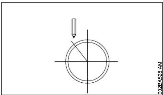
▶ Determine and mark direction of cut
▶ Determine sequence of cuts
Outer diameter is smaller than the maximum cutting depth
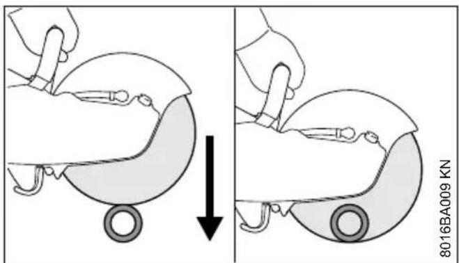
▶ Make one cut from the top to the bottom
Outer diameter is greater than the maximum cutting depth
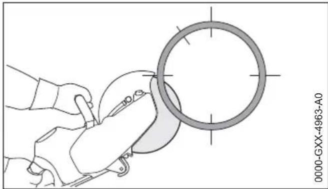
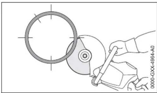
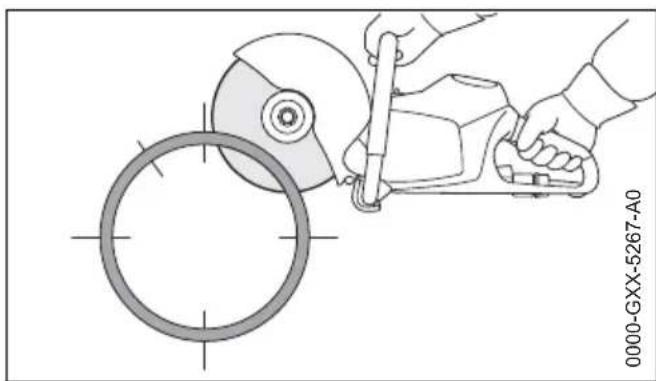
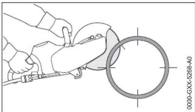
Plan first, then cut. Several cuts are needed – correct sequence is important.
5 Sample Applications English
natural_image
Technical illustration of a hand using a tool to cut a circular component, labeled '0000-GXX-4963-A0' (no other text or symbols)▶ Always start at the bottom, using the upper quarter of the abrasive cutting wheel for cutting
natural_image
Illustration of a hand using a tool to cut a circular component, no text or symbols present▶ Use the upper quarter of the abrasive cutting wheel for cutting the opposite lower side.
natural_image
Technical line drawing of a person using a power saw to cut a circular component (no text or symbols)▶ First lateral cut on the top half of the pipe
natural_image
Technical illustration of a cutting tool on a workpiece with a circular component, no text or symbols present- Second lateral cut in the marked area – never cut into the area of the last cut, to ensure a firm hold on the part of pipe to be cut
Only make the last top cut once all bottom and lateral cuts have been made.
natural_image
Technical illustration of a mechanical assembly with hands operating a tool and a circular component below (no text or symbols)▶ Last cut always from the top (approx. 15 % of the pipe circumference)
5.9 Concrete pipe – cut recess
Sequence of cuts (1 to 4) is important:
▶ First, cut hard-to-reach areas
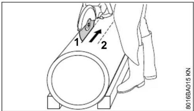
▶ Always make severing cuts so that the abrasive cutting wheel is not pinched
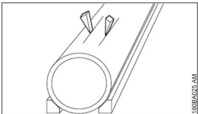
natural_image
Technical line drawing of a mechanical component with two protruding pins (no text or symbols)▶ Use wedges and/or leave ridges that are broken after cutting
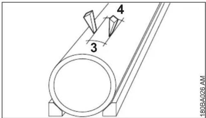
If the severed part remains in the recess after cutting (due to wedges, ridges used), do not make any further cuts – break the severed part
6 Cutting Wheels
Abrasive wheels are exposed to extremely high loads especially during freehand cutting.
Therefore only for use of approved and correspondingly labeled abrasive wheels with handheld machines as per EN 13236 (diamond) or EN 12413 (composite resin). Note maximum permissible speed of the abrasive wheel – risk of accident!
The abrasive wheels, which have been developed by STIHL in cooperation with renowned manufacturers of abrasive wheels, are of high quality and tailored precisely to the respective intended use as well as the engine performance of the cut-off machine.
They are of consistently outstanding quality.
6.1 Transport and storage
- Do not expose abrasive wheels to direct sunshine or other thermal stresses during transport and storage
- Avoid jolting and impacts
- Stack abrasive wheels flat on a level surface in the original packaging in a dry place where the temperature is as constant as possible
- Do not store abrasive wheels in the vicinity of aggressive fluids
- Store abrasive wheels in a frost-free place
7 Composite Abrasive Wheels
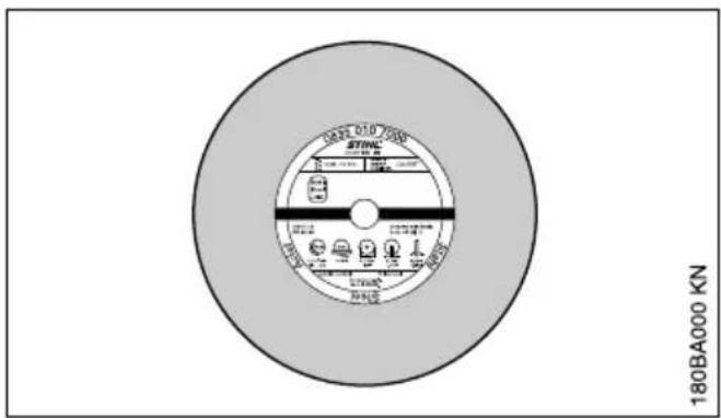
Composite resin abrasive wheels are also known as bound abrasive wheels.
Types:
- for dry applications
- for wet applications
The proper selection and use of composite resin abrasive wheels ensures economical use and avoids accelerated wear. The product code which appears on the label should help.
STIHL composite resin abrasive wheels are suitable, depending on the version, for cutting the following materials:
- Stone
– Ductile cast iron pipes - Steel; STIHL composite resin abrasive wheels are not suitable for cutting railway tracks
- Stainless steel
Do not cut any other materials – Risk of accident!
8 Diamond Abrasive Wheels
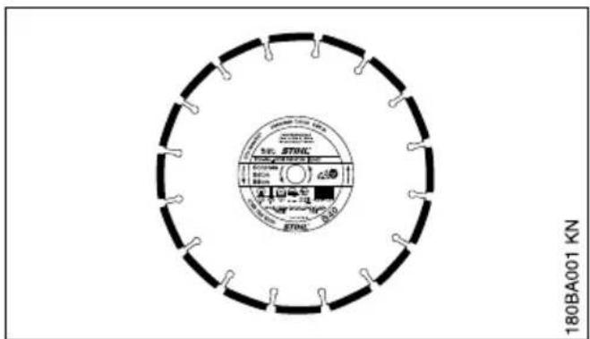
For wet applications.
The proper selection and use of diamond abrasive wheels ensures economical use and avoids accelerated wear. The product code which appears
- on the label and
8 Diamond Abrasive Wheels English
– on the packaging (table with recommendations for use) is an aid to selection
STIHL diamond abrasive wheels are suitable, depending on the version, for cutting the following materials:
- Asphalt
- Concrete
- Stone (hard stone)
- Abrasive concrete
- Fresh concrete
- Clay brick
- Clay pipe
Do not cut any other materials – Risk of accident!
Never use diamond abrasive wheels with side plating as they jam in the cut and can result in extreme kickback – Risk of accident!
8.1 Product Codes
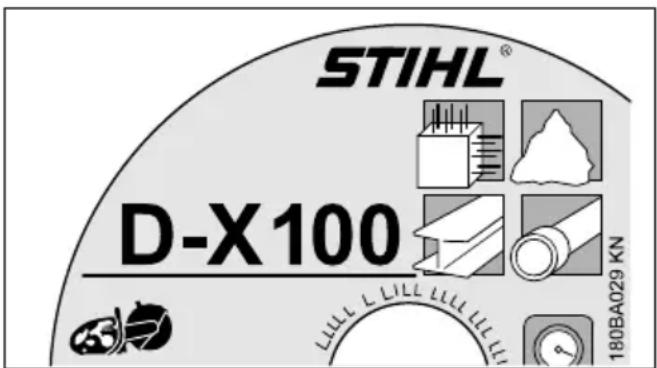
The product code is a combination of letters and numbers, consisting of up to four characters:
– the letters denote the main field of application of the abrasive wheel
8.3 Troubleshooting
8.3.1 Abrasive wheel
- the numbers denote the performance class of the STIHL diamond abrasive wheel
8.2 Axial and radial run-out
A faultless spindle bearing of the cut-off machine is necessary for a long service life and efficient functioning of the diamond abrasive wheel.
Using the abrasive wheel on a cut-off machine with a faulty spindle bearing can lead to deviations in radial and axial run-out.
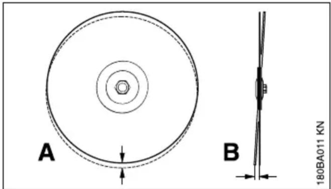
An excessively high radial run-out deviation (A) overloads individual diamond segments, which overheat in the process. This can lead to stress cracks in the parent wheel or to annealing of individual segments.
Deviations in axial run-out (B) result in higher thermal loading and wider cuts.
| Defects | Cause Remedy | |
| ragged edges or cut surfaces, crooked cutheavy wear on the sides of the segments | Deviation in radial or axial run-outAbrasive wheel gyrates use a new abrasive wheel | Contact a servicing dealer1)abrasive wheel |
| ragged edges, crooked cut, no cutting performance, generation of sparks | Abrasive wheel is dull; built-up edges with abrasive wheels for stone | Sharpen abrasive wheels for stone by briefly cutting through abrasive materials; replaceabrasive wheel for asphalt with a new one |
| poor cutting performance, high segment wear | Abrasive wheel is turning in the wrong direction | Mount abrasive wheel so that it turns in the right direction |
| Breakdowns or tears in the parent wheel and segment | Overloading use a new abrasive wheel | |
| Undercut Cutting in the wrong material use new abrasive wheel; | observe separating layers of various materials | |
8.3.2 Undercut
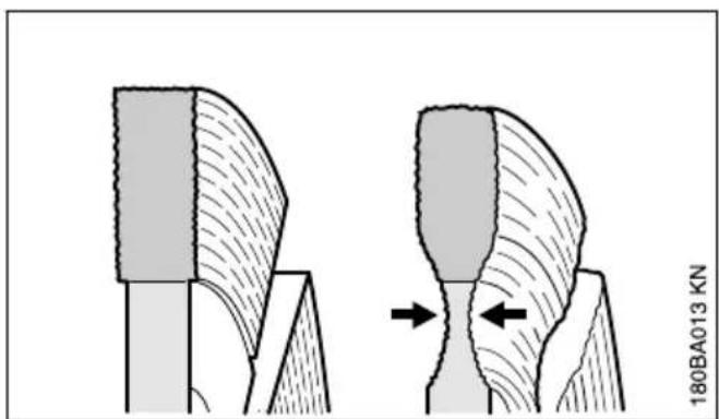
Do not cut into the base course (frequently chipped stones and gravel) when cutting roadway pavement – cutting in chipped stones and gravel is revealed by light-colored dust – excessive undercut may occur as a result – Danger of shattering!
8.3.3 Built-up edges, sharpen
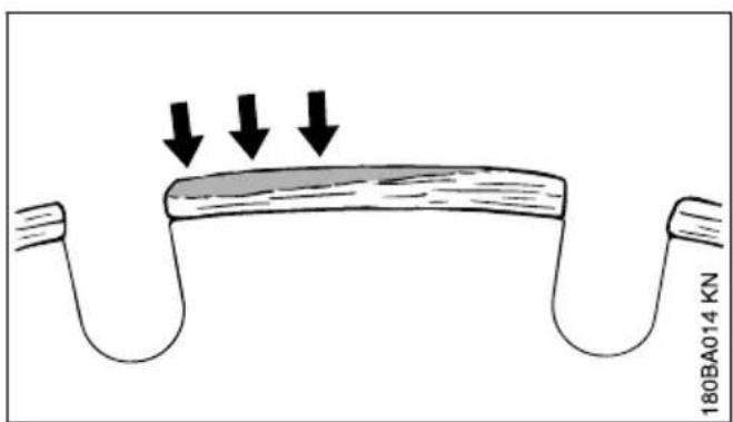
Built-up edges take the form of a light gray deposit on the tops of the diamond segments. This deposit on the segments clogs the diamonds and blunts the segments.
Built-up edges can form:
- when cutting extremely hard materials, e. g., granite
– with incorrect handling, e. g., excessive feed effort
Built-up edges increase vibration, reduce cutting performance, and cause formation of sparks.
At the first signs of built-up edges, immediately "sharpen" the diamond abrasive wheel – to do this, briefly cut through abrasive material such as e. g. sandstone, aerated concrete or asphalt.
Addition of water prevents the formation of built-up edges.
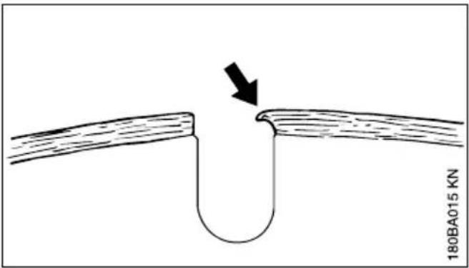
If work continues with dull segments, these may soften due to the high heat generated – the parent wheel is annealed and its strength is compromised – this can lead to stresses that are clearly recognizable by gyrations of the abrasive wheel. Do not continue to use the abrasive wheel – Risk of accident!
9 Mounting an Abrasive Wheel
Only fit or replace when the machine is switched off – retaining latch moved to ☐, battery removed.
9 Mounting an Abrasive Wheel English
9.1 Removing an abrasive wheel
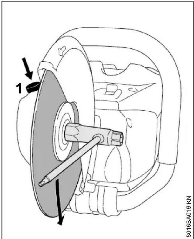
▶ Press and hold the spindle locking mechanism (1)
▶ Turn the shaft with the combination wrench until the shaft is blocked
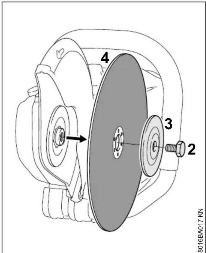
▶ Use the combination wrench to loosen the hexagon head screw (2)
▶ Release the spindle locking mechanism and unscrew the hexagon head screw (2)
▶ Remove the front thrust washer (3) from the shaft together with the abrasive wheel (4)
9.2 Fitting an abrasive wheel
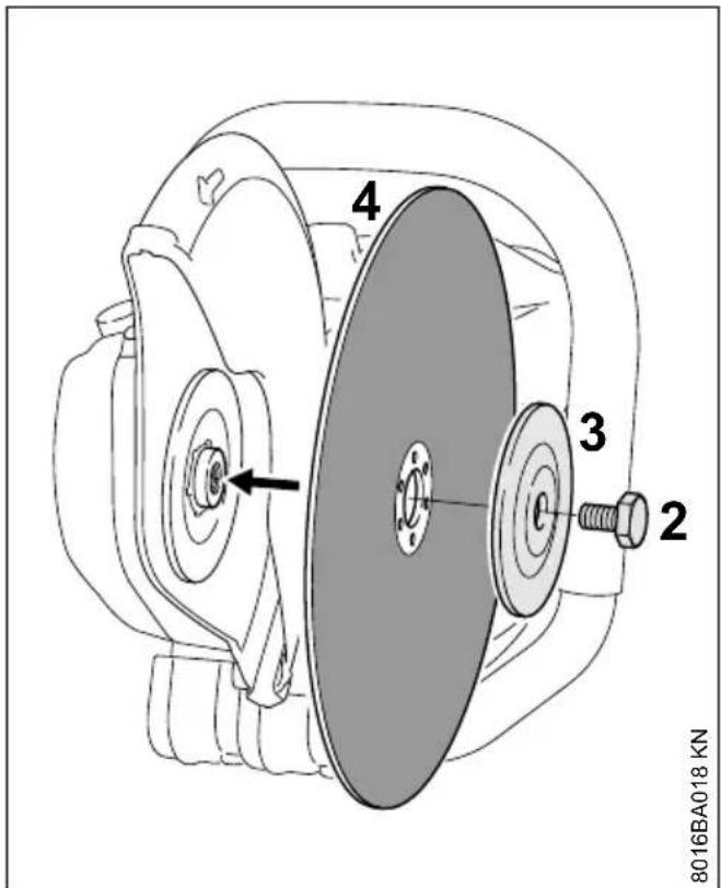
▶ Fit the new abrasive wheel (4)

Note the arrows indicating the direction of rotation on diamond abrasive wheels.
- Position the front thrust washer (3) so that the words "TOP SIDE" are visible
▶ Screw in the hexagon head screw (2)
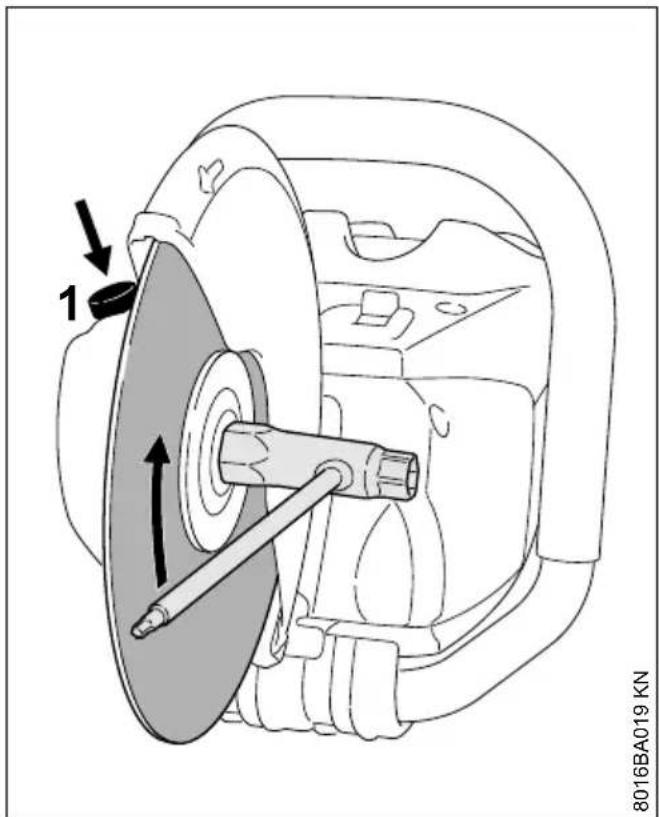
▶ Press and hold the spindle locking mechanism (1)
▶ Turn the shaft with the combination wrench until the shaft is blocked
- Tighten the hexagon head screw with the combination wrench – if using a torque wrench, refer to the "Specifications" for the tightening torque

WARNING
Never use two abrasive wheels at the same time. The uneven wear creates a risk of breaking and an injury hazard!
10 Connecting Charger to Power Supply
Power supply (mains) voltage and operating voltage must be the same.
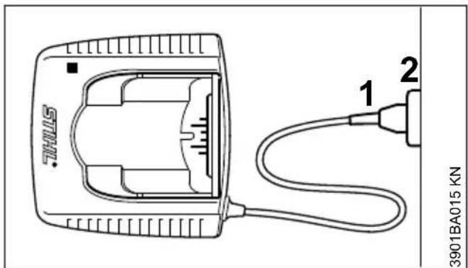
- Insert the plug (1) in the wall outlet (2).
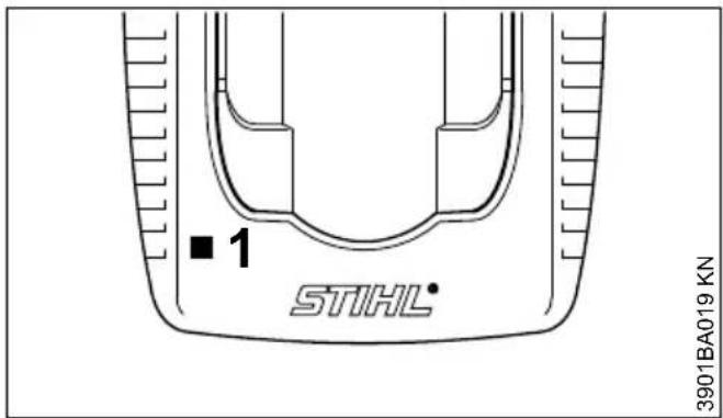
A self test is performed after the charger is connected to the power supply. During this process, the light emitting diode (1) on the charger lights up green for about 1 second, then red and goes off again.
11 Charging the Battery
A factory-new battery is not fully charged.
Recommendation: Fully charge the battery before using it for the first time.
- Connect the charger to the power supply – mains voltage and operating voltage of the charger must be the same – see "Connecting Charger to Power Supply".
Operate the charger only in enclosed and dry rooms at ambient temperatures between +5°C to +40°C (+41°F to +104°F)
Only charge dry batteries. Allow a damp battery to dry before charging.
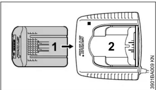
- Push the battery (1) into the charger (2) until noticeable resistance is felt – then push it as far as stop.
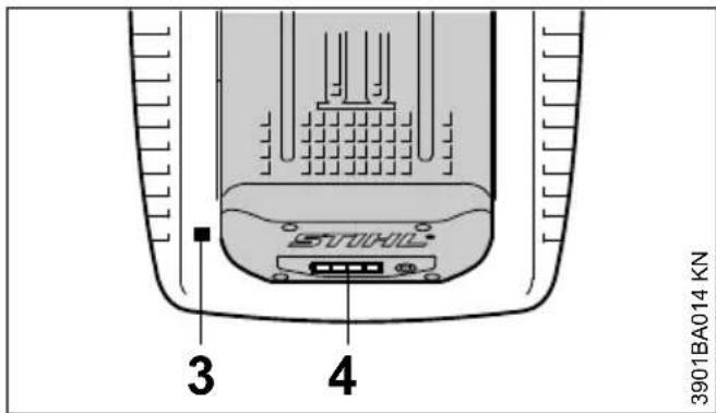
The LED (3) on the charger comes on when the battery is inserted – see "LED on Charger"
Charging begins as soon as the LEDs (4) on the battery glow green – see "LEDs on Battery".
The charge time is dependent on a number of factors, including battery condition, ambient temperature, etc., and may therefore vary from the times specified.
The battery heats up during operation in the power tool. If a hot battery is inserted in the charger, it may be necessary to cool it down before charging. The charging process begins only after the battery has cooled down. The time required for cooling may prolong the charge time.
The battery and charger heat up during the charging process.
11.1 AL 300, AL 500 Chargers
The AL 300 and AL 500 chargers are equipped with a battery cooling fan
11.2 AL 100 Charger
The AL 100 charger has no fan and waits for the battery to cool down before starting the charging process. The battery is cooled by heat transfer to the ambient air.
11.3 End of Charge
The charger switches itself off automatically when the battery is fully charged:
- LEDs on the battery go off.
- The LED on the charger goes off.
- The charger's fan is switched off (if charger is so equipped)
Remove the fully charged battery from the charger.
12 LEDs on Battery
Four LEDs show the battery's state of charge and any problems that occur in the battery or machine.
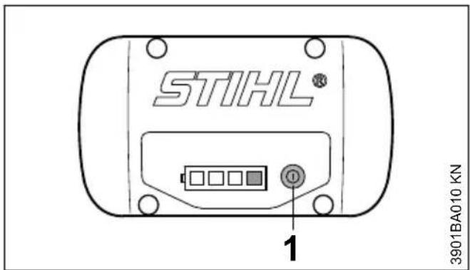
- Press button (1) to activate the display – the display goes off automatically after 5 seconds.
The LEDs can glow or flash green or red.

LED glows continuously green.

LED flashes green.

LED glows continuously red.

LED flashes red.
12.1 During charging
The LEDs glow continuously or flash to indicate the progress of charge.
A green flashing LED indicates the capacity that is currently being charged.
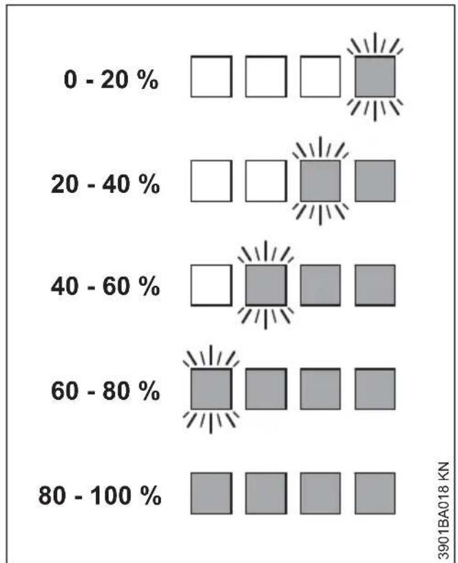
bar
| Range (%) | White Square | Gray Square | |---|---|---| | 0 - 20 % | □ | □ | | 20 - 40 % | □ | □ | | 40 - 60 % | □ | □ | | 60 - 80 % | □ | □ | | 80 - 100 % | □ | □ |The LEDs on the battery go off automatically when the charge process is completed.
If the LEDs on the battery flash or glow red – see "If the red LEDs glow continuously / flash".
12.2 During Operation
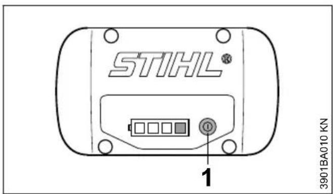
- Press button (1) to activate the display – the display goes off automatically after 5 seconds.
The green LEDs glow continuously or flash to indicate the state of charge.
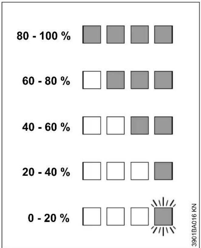
heatmap
| Range | 0 - 20 % | 20 - 40 % | 40 - 60 % | 60 - 80 % | 80 - 100 % | | :--- | :--- | :--- | :--- | :--- | :--- | | Dark Grey Square | □ | □ | □ | □ | □ | 3901BA016 KN (labeled) at bottom right.If the LEDs on the battery flash or glow red – see "If the red LEDs glow continuously / flash".
13 LED on Charger English
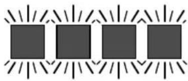
12.3 If the red LEDs glow continuously / flash
A

B
natural_image
Four identical dark squares arranged in a row with radiating lines, no text or symbols present.C

D

natural_image
Simple diagram with three dark squares surrounded by radiating lines and a white square (no text or symbols)3901BA041 KN
| A 1 | LED glows continuously red: | Battery is too hot ^1) ^2) /cold ^1) |
| B 4 | LEDs flash red Malfunction in battery ^3) | |
| C 3 | LEDs glow continuously red: | Machine is too hot – allow it to cool down. |
| D 3 | LEDs flash red Malfunction in machine ^4) |
13 LED on Charger
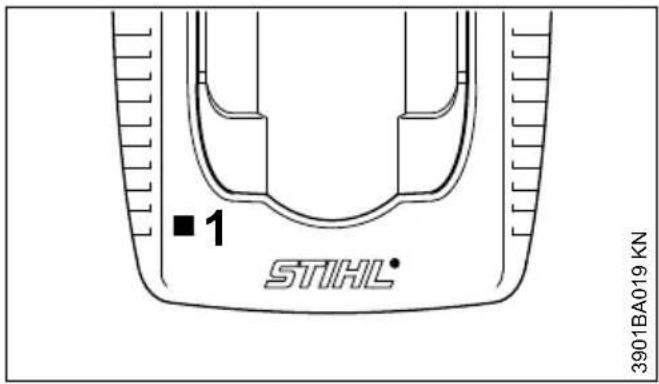
The LED (1) on the charger may glow continuously green or flash red.
13.1 Green continuous light ...
... indicates the following:
- is being charged
– is too hot and must cool down before charging
See also "LEDs on battery".
The green LED on the charger goes off as soon as the battery is fully charged.
13.2 Red flashing light ...
... may indicate the following:
- No electrical contact between battery and charger – remove and refit the battery
- Malfunction in battery – see also "LEDs on Battery".
- Malfunction in charger – have checked by a servicing dealer. STIHL recommends an authorized STIHL servicing dealer.
14 Connecting the water supply
Only with wet cuts:
- Connect the hose to the water supply network
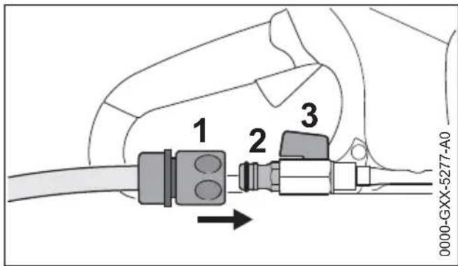
▶ Push the coupling (1) on to the hose connector (2)
- when connected to the water supply network, open the tap
- before starting work, open the shut-off valve (3) and allow water to flow to the abrasive wheel
The water flow rate can be set via the shut-off valve (3).
After finishing work:
▶ Switch off the machine
▶ Close the shut-off valve (3).
- Disconnect the cut-off machine from the water supply network
Water can also be supplied via the pressurized water tank (special accessory).
15 Switching On
When delivered, the battery is not fully charged. It is advisable to charge the battery completely before using it for the first time.
Before inserting the battery, remove the battery compartment cover if there is one; to do this, press both safety catches at the same time – cover is unlocked – remove the cover
15.1 Inserting the battery

- Insert the battery (1) into the battery compartment of the machine – battery slides into the compartment – press gently until it clicks into
place – top of battery must be flush with the top edge of the housing
15.2 Switching on the machine
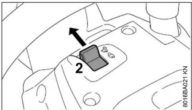
- Unlock the machine by moving the locking lever (2) to ☐
▶ Make sure you have a firm and secure stance - Stand up straight – hold the machine in a relaxed manner
▶ The abrasive cutting wheel must not touch any objects or the ground
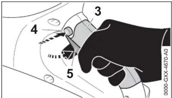
- Hold the machine with both hands – left hand on the handlebar – right hand in the grip area (3) of the rear handle
▶ Press the trigger switch lockout (4) - Press and hold the trigger switch (5) – the engine starts running
The engine only runs if the locking lever (2) is set at ☐ and if the trigger switch lockout (4) and trigger switch (5) are actuated at the same time.
16 Switching Off
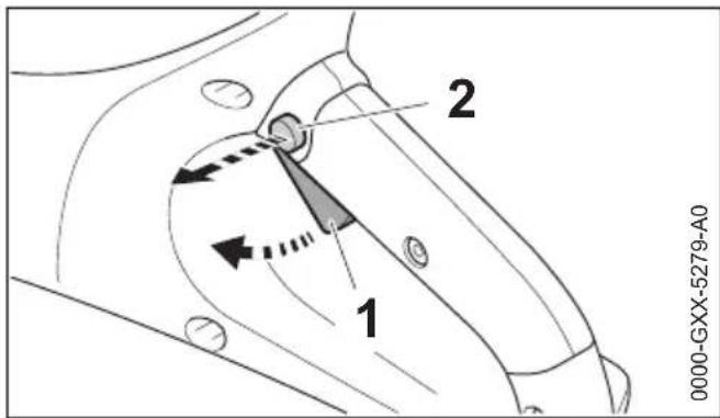
▶ Release the trigger switch (1) and trigger switch lockout (2)
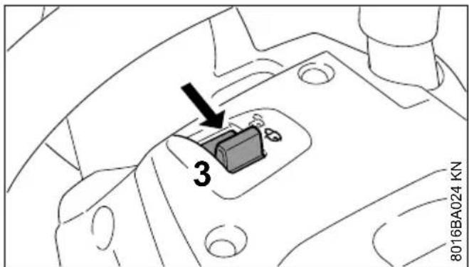
- Set the retaining latch (3) to ☐ – machine is locked so that it cannot be switched on
During breaks and after work, remove the battery from the machine.
NOTICE
If the battery is not removed, there is the risk that the plug-in contacts on the cut-off machine and battery become corroded. Such corrosion can cause irreparable damage to the cut-off machine and battery.
16.1 Removing the battery
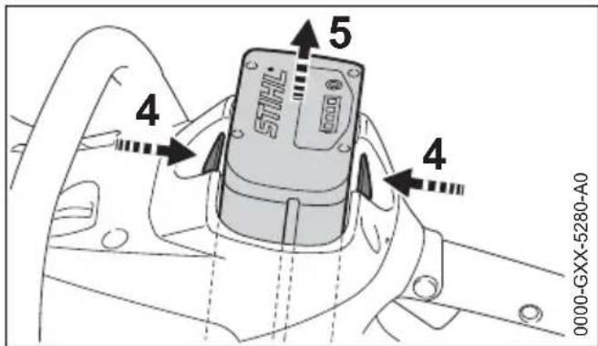
- Press both safety catches at the same time (4) – this unlocks the battery (5)
▶ Remove the battery (5) from the housing
When the machine is not in use, shut it off so that it does not endanger others.
Secure it against unauthorized use.
17 Storing the Machine
▶ Set retaining latch to 🔒
▶ Remove the battery
▶ Remove the abrasive wheel
- Thoroughly clean the machine, especially the ventilation slots
▶ Store machine in a safe and dry place. Protect against unauthorized use (e. g., by children)
NOTICE
If the battery is not removed, there is the risk that the plug-in contacts on the cut-off machine and battery become corroded. Such corrosion can cause irreparable damage to the cut-off machine and battery.
17.1 Battery compartment cover (special accessory)
The cover protects the empty battery compartment against dirt.
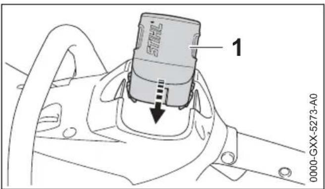
▶ After work, insert the cover (1) in the compartment until the cover audibly snaps into place
17.2 Battery storage
▶ Remove the battery from the machine or charger
▶ Store in a closed, dry space and keep in a secure location. Protect against unauthorized use (e.g., by children) and dirt
- Do not store backup batteries unused – use them in alternation
For optimum service life, store the battery at a charge of approx. 30 %.
17.3 Storing the charger
▶ Remove the battery
▶ Disconnect the power plug
- Store charger in a closed, dry space and keep in a secure location. Protect against unauthorized use (e.g., by children) and dirt
18 Maintenance and Care
| The following intervals apply for normal operating conditions. The specified intervals must be shortened accordingly when working for longer than normal or under difficult cutting conditions (extensive dust, etc.).Move the retaining latch to ☐ and remove the battery before performing any work on the power tool. | Before starting work | At the end of work and/or daily | Weekly | Monthly | Annually | If faulty | If damaged | As required | |
| Complete unit visual inspection | ction (condition) | X | |||||||
| Clean X | |||||||||
| Control handles (locking lever, trigger switch lock-out and trigger switch) | Function test X | ||||||||
| Clean XX | |||||||||
| Cool air intake port Visual inspection | inspection X | ||||||||
| Clean X | |||||||||
| Accessible screws, nuts and bolts | Tighten X | ||||||||
| Battery Visual inspection | XX | ||||||||
| remove X | |||||||||
| Battery compartment | clean | X | X | ||||||
| check | X | X | |||||||
| Water connection, water system | check | X | X | ||||||
| Have it repaired by a specialist dealer1) | X | ||||||||
| Cutting wheel | Check | XXX | |||||||
| replace | XX | ||||||||
| Guide plate (underneath machine) | check | X | |||||||
| Replace1) | XX | ||||||||
| Safety information label | replace | X | |||||||
| 1)STIHL recommends STIHL dealers | |||||||||
19 Minimize Wear and Avoid Damage
Observing the instructions in this manual helps reduce the risk of unnecessary wear and damage to the power tool.
The power tool must be operated, maintained and stored with the due care and attention described in this instruction manual.
The user is responsible for all damage caused by non-observance of the safety precautions, oper-
ating and maintenance instructions. This includes in particular:
- Alterations or modifications to the product not approved by STIHL.
- Using tools or accessories which are neither approved or suitable for the product or are of a poor quality.
- Using the product for purposes for which it was not designed.
– Using the product for sports or competitive events.
- Consequential damage caused by continuing to use the product with defective components.
19.1 Maintenance Work
All the operations described in the "Maintenance Chart" must be performed on a regular basis. If these maintenance operations cannot be performed by the owner, they should be performed by a servicing dealer.
STIHL recommends that you have servicing and repair work carried out exclusively by an authorized STIHL servicing dealer. STIHL dealers are regularly given the opportunity to attend training courses and are supplied with the necessary technical information.
If these maintenance operations are not carried out as specified, the user assumes responsibility for any damage that may occur. Among other things, this includes:
- Damage to the motor due to neglect or deficient maintenance (e.g. not cleaning cooling air inlets).
– Damage to the charger caused by incorrect electrical connection (voltage). - Corrosion and other consequential damage to the machine, battery and charger due to improper storage and use.
– Damage to the product resulting from the use of poor quality replacement parts.
19.2 Wear parts
Some parts of the machine are subject to normal wear and tear even when the machine is used in conformity with its intended use. These parts must be replaced in due time, depending on the nature and duration of use. These include, among others:
- Abrasive wheel
- Battery
20 Main Parts
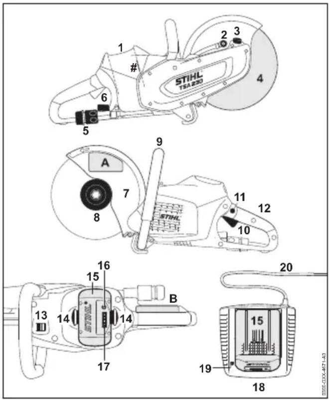
1 Battery compartment
2 Water nozzle
3 Spindle locking mechanism
4 Abrasive cutting wheel
5 Water attachment
6 Shut-off valve
7 Guard
8 Front thrust washer
9 Handlebar
10 Trigger
11 Trigger switch lockout
12 Rear handle
13 Retaining latch
14 Safety catch for locking battery
15 Battery
16 Pushbutton for activating the light-emitting diodes (LEDs) on the battery
17 Light-emitting diodes (LEDs) on battery
18 Charger
19 Light-emitting diode (LED) on charger
20 Power cord with power plug
Machine no.
A Safety information label
B Safety information label
21 Specifications
21.1 Battery
Type: Lithium-Ion Designation: AP
The machine may be operated only with original STIHL AP rechargeable batteries.
Running time is dependent on the energy content of the battery.
21.2 Abrasive wheels
The quoted maximum permissible operating speed of the abrasive wheel must be greater than or equal to the maximum spindle speed of the cut-off machine used.
Max. spindle speed: 6650 rpm
Outside diameter: 230 mm (9")
Max. thickness 3 mm
Bore diameter/spindle diameter: 22.23 mm (7/8")
Tightening torque: 20 Nm (177 lbf. in.)
Composite resin abrasive wheels Minimum outside diameter of 80 mm thrust washers: (3.150 in.) Max. depth of cut: 70 mm (2.756 in.)
Diamond abrasive wheels Minimum outside diameter of thrust washers: 80 mm (3.150 in.) Max. depth of cut: 70 mm (2.756 in.)
21.3 Weight
without battery, without abrasive 3.9 kg (8.6 lbs.) wheel, with water connection
21.4 Water supply
Max. pressure of water supply: 4 bar (58 psi)
21.5 Sound and vibration levels
For further details concerning compliance with the Physical Agents Directive Vibration 2002/44/EEC, see www.stihl.com/vib/
21.5.1 Values when cutting concrete under pressure with diamond abrasive wheel
Sound pressure level L_peq to 103 dB(A) EN 60745-2-22: Sound power level 114 dB(A) L_w to
EN 60745-2-22: Vibration level a_hv,eq to EN 60745-2-22: Left handle: 3.5 m/s ^2
Sound pressure level L_peq to EN 60745-2-22: Handle, right 103 dB(A) 3.5 m/s ^2
21.5.2 Values when maximum engine speed without load with diamond abrasive wheel
Sound pressure 93 dB(A) level L_peq to EN 60745-2-3: Sound power level 104 dB(A) L_w to EN 60745-2-3:
21.5.3 Values when maximum engine speed without load with composite resin abrasive wheel
Sound pressure 72 dB(A) level L_peq to EN 60745-2-3: Sound power level 83 dB(A) L_w to EN 60745-2-3:
The vibration values quoted above have been measured according to a standardized test procedure and may be used to compare electric power tools.
Depending on the type of usage, the vibrations that actually occur may differ from the values quoted.
The vibration values quoted may be used for an initial assessment of the user's exposure to vibrations.
The actual exposure to vibrations has to be evaluated. This process may also take into account times during which the electric power tool is switched off and times during which it is switched on but running without load.
Observe measures to reduce vibration exposure to protect the user – see section on "Vibrations" in chapter on "Safety Precautions and Working Techniques".
The K-factor in accordance with Directive 2006/42/EC is 2.0 dB(A) for the sound pressure level and sound power level; the K-factor in accordance with Directive 2006/42/EC is 2.0 m/s ^2 for the vibration level.
21.6 Transporting
STIHL rechargeable batteries comply with the requirements stipulated in UN-Manual Tests and Criteria, Part III, Subsection 38.3.
22 Troubleshooting English
The user can transport STIHL rechargeable batteries by road without additional conditions to the place where the machine is to be used.
The lithium ion batteries included are subject to the provisions of hazardous goods law.
When shipped by a third party (e.g., air transport or a shipping company), special packaging and identification requirements must be followed.
When preparing the item for shipment, a hazardous goods expert must be consulted. Please comply with any additional national regulations.
Pack the rechargeable battery so that it cannot move inside the packaging.
Further transport instructions - see www.stihl.com/safety-data-sheets
21.7 REACH
REACH is an EC regulation and stands for the Registration, Evaluation, Authorization and Restriction of Chemical substances.
For information on compliance with the REACH regulation (EC) No. 1907/2006 see
www.stihl.com/reach
22 Troubleshooting
| Always remove the battery before carrying out any work on the power tool. | ||
| Fault Cause Remedy | ||
| Power tool does not run when switched on | No electrical contact between power tool and battery | Remove battery, visually inspect the contacts and reinsert the battery |
| Battery charge state is too low (1 LED on battery flashes green) | Charging the battery | |
| Battery too hot / too cold (1 LED on battery is red) | Let the battery cool down / let the battery warm up gradually at temperatures of approx. 15°C to 20 C (59°F to 68°F) | |
| Error in battery (4 LEDs on battery flash red) | Remove the battery from the power tool and reinsert it. Switch on the power tool – if the LEDs still flash, the battery is faulty and must be replaced | |
| Unit too hot (3 LEDs on battery are red) | Let the power tool cool off | |
| Electromagnetic problem or fault in power tool (3 LEDs on battery flash red) | Remove the battery from the power tool and reinsert it. Switch the power tool on – if the LEDs still flash, the power toolhas a malfunction and must be checked by a servicing dealer 1) | |
| Moisture in the power tool and/or battery | Let the power tool/battery dry | |
| Power tool cuts out during operation | Battery or power tool electronics too hot | Remove battery from the power tool, let battery and power tool cool off |
| Electric or electromagnetic interference | Remove battery and reinsert it | |
| Runtime is too short Battery is not completely charged | Charging the battery | |
| Service life of battery has been reached or exceeded | ||
| Battery gets stuck during insertion in the power tool/charger | Guides dirty Carefully clean guides | |
| Battery does not charge although the LEDs on the charger are green | Battery too hot / too cold (1 LED on battery is red) | Let the battery cool down / let the battery warm up gradually at temperatures of approx. 15°C to 20°C (59°F to 68°F) Operate the charger only in a closed, dry space at ambient temperatures of +5°C to +40°C (41°F to 104°F) |
| Light emitting diode on charger flashes red | No electrical contact between charger and battery | Remove battery and reinsert it |
| Error in battery (4 LEDs on battery flash red for approx. 5 seconds) | Remove the battery from the power tool and reinsert it. Switch on the power tool – if the LEDs still flash, the battery is faulty and must be replaced | |
| Fault in charger Have charger checked by servicing dealer 1) | ||
| 1)STIHL recommends STIHL dealers | ||
23 Maintenance and Repairs
Users of this machine may only carry out the maintenance and service work described in this user manual. All other repairs must be carried out by a servicing dealer.
STIHL recommends that you have servicing and repair work carried out exclusively by an authorized STIHL servicing dealer. STIHL dealers are regularly given the opportunity to attend training courses and are supplied with the necessary technical information.
When repairing the machine, only use replacement parts which have been approved by STIHL for this power tool or are technically identical.
Only use high-quality replacement parts in order to avoid the risk of accidents and damage to the machine.
STIHL recommends the use of original STIHL replacement parts.
Original STIHL parts can be identified by the STIHL part number, the STIHL ^ logo and the STIHL parts symbol G_ (the symbol may appear alone on small parts).
24 Disposal
Contact the local authorities or your STIHL servicing dealer for information on disposal.
Improper disposal can be harmful to health and pollute the environment.
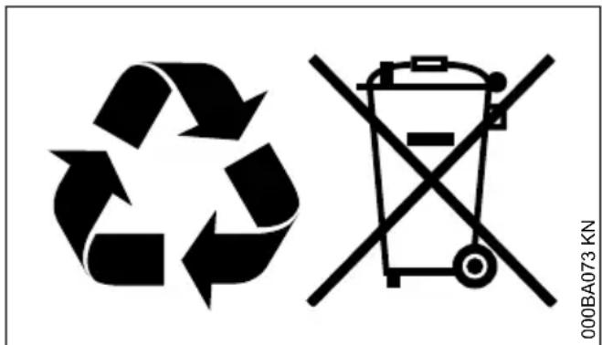
▶ Take STIHL products including packaging to a suitable collection point for recycling in accordance with local regulations.
- Do not dispose with domestic waste.
25 EC Declaration of Con- formity
declare under our sole responsibility that
Designation: Cordless cut-off machines
Make: STIHL
Series: TSA 230
Serial identification num- 4864
ber:
conforms to the specifications of Directives 2006/42/EC, 2014/30/EU and 2011/65/EC and has been developed and built in compliance with the versions of the following standards valid at the production date:
EN 55014-1, EN 55014-2, EN 60745-1, EN 60745-2-22
Technical documents deposited at:
The year of construction, the country of manufacture and the machine number are shown on the machine.
Done at Waiblingen, 15.07.2021
Director Product Certification & Regulatory Affairs
CE
26 UKCA Declaration of Conformity
declare under our sole responsibility that
Designation: Cordless cut-off machines
Make: STIHL
Series: TSA 230
Serial identification num- 4864
ber:
complies with the relevant provisions of the UK regulations Supply of Machinery (Safety) Regulations 2008, Electromagnetic Compatibility Regulations 2016 and The Restriction of the Use of Certain Hazardous Substances in Electrical and Electronic Regulations 2012 and has been developed and manufactured in accordance with the versions of the following standards valid on the date of manufacture:
EN 55014-1, EN 55014-2, EN 60745-1, EN 60745-2-22
Technical documents deposited at:
The year of construction, the country of manufacture and the machine number are shown on the machine.
Done at Waiblingen, 15.07.2021
Director Product Certification & Regulatory Affairs
UK CA
27 General Power Tool Safety Warnings
This chapter reproduces the pre-formulated, general safety precautions specified in the EN 60745 European standard for hand-held motor-operated electric tools. STIHL is required by law to print these standardized texts verbatim.
The safety precautions and warnings on avoiding an electric shock given under "2) Electric Precautions" do not apply to STIHL cordless electric power tools

WARNING
Read all safety warnings and instructions. Failure to follow the warnings and instructions may result in electric shock, fire and/or serious injury.
Save all warnings and instructions for future reference.
The term "power tool" in the warnings refers to your mains-operated (corded) power tool or battery-operated (cordless) power tool.
27.1 1) Work area safety
a) Keep work area clean and well lit. Cluttered or dark areas invite accidents.
b) Do not operate power tools in explosive atmospheres, such as in the presence of flammable liquids, gases or dust. Power tools create sparks which may ignite the dust or fumes.
c) Keep children and bystanders away while operating a power tool. Distractions can cause you to lose control.
27.2 2) Electrical safety
a) Power tool plugs must match the outlet. Never modify the plug in any way. Do not use any adapter plugs with earthed (grounded) power tools. Unmodified plugs and matching outlets will reduce risk of electric shock.
b) Avoid body contact with earthed or grounded surfaces, such as pipes, radiators, ranges and refrigerators. There is an increased risk of electric shock if your body is earthed or grounded.
c) Do not expose power tools to rain or wet conditions. Water entering a power tool will increase the risk of electric shock.
d) Do not abuse the cord. Never use the cord for carrying, pulling or unplugging the power tool. Keep cord away from heat, oil, sharp edges or moving parts. Damaged or entangled cords increase the risk of electric shock.
e) When operating a power tool outdoors, use an extension cord suitable for outdoor use. Use of a cord suitable for outdoor use reduces the risk of electric shock.
f) If operating a power tool in a damp location is unavoidable, use a residual current device (RCD) protected supply. Use of an RCD reduces the risk of electric shock.
27.3 3) Personal safety
a) Stay alert, watch what you are doing and use common sense when operating a power tool. Do not use a power tool while you are tired or under the influence of drugs, alcohol or medication. A moment of inattention while operating power tools may result in serious personal injury.
b) Use personal protective equipment. Always wear eye protection. Protective equipment such as dust mask, non-skid safety shoes, hard hat, or hearing protection used for appropriate conditions will reduce personal injuries.
c) Prevent unintentional starting. Ensure the switch is in the off-position before connecting to power source and/or battery pack, picking up or carrying the tool. Carrying power tools with your finger on the switch or energising power tools that have the switch on invites accidents.
d) Remove any adjusting key or wrench before turning the power tool on. A wrench or a key left attached to a rotating part of the power tool may result in personal injury.
e) Do not overreach. Keep proper footing and balance at all times. This enables better control of the power tool in unexpected situations.
f) Dress properly. Do not wear loose clothing or jewellery. Keep your hair, clothing and gloves away from moving parts. Loose clothes, jewellery or long hair can be caught in moving parts.
g) If devices are provided for the connection of dust extraction and collection facilities,
27 General Power Tool Safety Warnings English ensure these are connected and properly used. Use of dust collection can reduce dust-related hazards.
27.4 4) Power tool use and care
a) Do not force the power tool. Use the correct power tool for your application. The correct power tool will do the job better and safer at the rate for which it was designed.
b) Do not use the power tool if the switch does not turn it on and off. Any power tool that cannot be controlled with the switch is dangerous and must be repaired.
c) Disconnect the plug from the power source and/or the battery pack from the power tool before making any adjustments, changing accessories, or storing power tools. Such preventive safety measures reduce the risk of starting the power tool accidentally.
d) Store idle power tools out of the reach of children and do not allow persons unfamiliar with the power tool or these instructions to operate the power tool. Power tools are dangerous in the hands of untrained users.
e) Maintain power tools. Check for misalignment or binding of moving parts, breakage of parts and any other condition that may affect the power tool's operation. If damaged, have the power tool repaired before use. Many accidents are caused by poorly maintained power tools.
f) Keep cutting tools sharp and clean. Properly maintained cutting tools with sharp cutting edges are less likely to bind and are easier to control.
g) Use the power tool, accessories, tool bits etc. in accordance with these instructions, taking into account the working conditions and the work to be performed. Use of the power tool for operations different from those intended could result in a hazardous situation.
27.5 5) Battery tool use and care
a) Recharge the batteries only in chargers specified by the manufacturer. A charger that is suitable for one type of battery pack may create a risk of fire when used with another battery pack.
b) Use power tools only with specifically designated battery packs. Use of any other battery packs may create a risk of injury and fire.
c) When battery pack is not in use, keep it away from other metal objects, like paper clips, coins, keys, nails, screws or other small objects that could make a connection from one terminal to another. Shorting the battery terminals together may cause burns or a fire.
d) Misuse may cause liquid to escape from the battery. Avoid contact with the liquid. If contact accidentally occurs, flush with water. If liquid contacts eyes, additionally seek medical help. Liquid ejected from the battery may cause irritation or burns.
27.6 6) Service
a) Have your power tool serviced by a qualified repair person using only identical replacement parts. This will ensure that the safety of the power tool is maintained.
27.7 7) Safety instructions for abrasive wheel applications
27.7.1 Safety instructions for cut-off machines
a) The guard for the electrical power tool must be mounted securely and set to achieve a maximum level of safety, i. e. the smallest possible part of the abrasive element points openly towards the operator. Make sure that you and no other person is outside the area of the rotating grinding wheel. The guard is designed to protect the operator against fragments and accidental contact with the abrasive element.
b) Use only bound reinforced or diamond-tipped abrasive wheels for your electrical power tool. Just because the accessory can be mounted to the electrical power tool, this does not guarantee safe use.
c) The permissible speed of the tool being used must be at least as high as the maximum speed indicated on the electrical power tool. An accessory that rotates quicker than permitted can break and fly around.
d) Abrasive elements must only be used for the recommended applications. For example: Never grind with the side surface of an abrasive wheel. Abrasive wheels are designed to remove material with the edge of the wheel. Lateral forces applied to these abrasive elements can break them.
e) Always use an undamaged clamping flange of the correct size and form for the abrasive
English 27 General Power Tool Safety Warnings
wheel you have chosen. Suitable flanges support the abrasive wheel and reduce the risk of the abrasive wheel breaking.
f) Do not use worn abrasive wheels from larger electrical power tools. Abrasive wheels for larger electrical power tools are not designed for the high engine speeds of smaller electrical power tools and can break.
g) The outer diameter and thickness of the tool being used must correspond to the dimensions of your electrical power tool. Incorrectly measured tools that are used cannot be adequately shielded or controlled.
h) Abrasive wheels and flanges must fit exactly onto the grinding spindle of your electrical power tool. Tool bits that do not fit exactly onto the grinding spindle of the electrical power tool, rotate unevenly, vibrate a lot and can result in loss of control.
i) Do not use damaged abrasive wheels. Before each use, check the abrasive wheels for splitting and cracks. If the electrical power tool or abrasive wheel falls, check if it is damaged or use an undamaged abrasive wheel. Once you have checked the abrasive wheel and started it, make sure that you and everyone else nearby remain outside of the area of the rotating abrasive wheel and allow the machine to run for a minute at maximum speed. Damaged abrasive wheels usually break during this test period.
j) Wear personal protective equipment. Depending on the operation, wear full face protection, eye protection or safety glasses. Where appropriate, wear a dust mask, ear protection, protective gloves or a special apron that keeps small ground particles and material particles away from you. Eyes must be protected against foreign bodies flying around that occur with certain applications. The dust mask or respirator must filter the dust created during the operation. If subjected to loud noise for a longer period of time, you may suffer from loss of hearing.
k) Make sure that other persons keep a safe distance to your work area. Anyone entering the work area must wear personal protective equipment. Fragments from the workpiece or broken tool bits can fly off and cause injuries even when the person is outside of the direct work area.
I) Hold the machine only by the insulated handle surfaces when carrying out work where
the tool bit can hit hidden power lines. Contact with a live line can also render metal machine parts live and cause an electric shock.
n) Never put the electrical power tool down before the tool bit has fully stopped. The rotating tool bit could make contact with the surface, causing you to loose control of the electrical power tool.
o) Do not leave the electrical power tool running whilst carrying it. Your clothing may get caught in the rotating tool bit and the tool bit may penetrate your body.
p) Clean the vents of your electrical power tool regularly. The engine fan attracts dust into the housing and the large volume of metal dust collected can be an electrical hazard.
q) Do not use the electrical power tool near combustible materials. Sparks can ignite these materials.
27.8 8) Additional safety instructions for abrasive wheel applications
27.8.1 Kickback and associated safety instructions
Kickback is the sudden reaction as a result of a catching or blocked rotating abrasive wheel. Catching and blocking causes the rotating tool bit to stop abruptly. An uncontrolled electrical power tool is thereby accelerated against the direction of rotation of the tool bit at the blockage site.
If for example an abrasive wheel catches or blocks in the workpiece, the edge of the abrasive wheel that penetrates the workpiece can be caught, thereby causing the abrasive wheel to break away or a kickback. The abrasive wheel then travels towards or away from the operator depending on the direction of rotation of the wheel at the blockage site. Abrasive wheels can also break in this instance.
A kickback is the result of the incorrect or faulty use of the electrical power tool. It can be prevented by taking suitable measures, as described below.
a) Hold the electrical power tool firmly and make sure your body and arms are in a position so that you can catch the kickback forces. Always use the additional handle, if available, to maintain the best possible control of kickback forces or reactive torques during start-up. The operator can control the
kickback and reactive forces by taken suitable precautions.
b) Never place your hand near the rotating tool bits. The tool bit can move across your hand in the event of a kickback.
c) Avoid the area in front of and behind the rotating abrasive wheel. The kickback drives the electrical power tool in a direction that is opposite to the movement of the abrasive wheel at the blockage site.
d) Work with great care around corners, sharp edges, etc. Prevent tool bits of the workpiece from recoiling and jamming. The rotating tool bit tends to jam when it hits corners, sharp edges or if it ricochets. This results in the loss of control or kickback.
e) Do not use a chain or toothed saw blade or a segmented diamond wheel with more than a 10 mm wide slit. Such tool bits often cause kickback or the loss of control of the electrical power tool.
f) Avoid the blocking of the abrasive wheel or a surface pressure that is too high. Do not make cuts that are too deep. Overloading the abrasive wheel increases its stress level and the likelihood of skewing or blocking, and thereby the possibility of a kickback or breakage of the abrasive element.
g) If the abrasive wheel jams or if you interrupt your work, switch off the machine and hold it still until the wheel stops. Never try to remove an abrasive wheel that is still rotating out of the cut as this may lead to a kickback. Determine and rectify the cause of the jam.
h) Do not switch the electrical power tool back if it is still in the workpiece. Allow the abrasive wheel to reach its full speed before continuing carefully with the cut. Otherwise the wheel may catch, jump out of the workpiece or cause a kickback.
i) Support plates or large workpieces to reduce the risk of a kickback due to a jammed abrasive wheel. Large workpieces can bend under their own weight. The workpiece must be supported on both sides of the wheel, both near the cut and at the edge.
j) Be especially careful with "pocket cuts" in existing walls or other blind areas. If the penetrating abrasive wheel cuts into gas or water pipes, electric cables or other objects, this can cause a kickback.
Índice
natural_image
Line drawing of hands using a STIHL TSA 230 power cutter on a cutting board (no text or symbols on the diagram itself)natural_image
Illustration of hands using a STIHL 194-230 angle grinder on a cutting tool (no text or symbols on the diagram itself)natural_image
Technical line drawing of a mechanical component embedded in a textured surface (no text or symbols)natural_image
Technical illustration of a mechanical assembly with a tool and circular component (no text or symbols)natural_image
Technical illustration of a hand using a tool to cut a circular component, no text or symbols presentnatural_image
Technical illustration of a person using a saw on a cutting tool, with no visible text or symbols.natural_image
Technical illustration of a cutting tool and a circular component, no text or symbols presentnatural_image
Technical illustration of a mechanical assembly with hands operating a tool, showing a circular component and a bracket (no text or symbols)natural_image
Technical line drawing of a mechanical component with two protruding pins (no text or symbols)2.8 Vinkelslip, spindellagring
natural_image
Line drawing of hands using a STIHL TSA 230 power cutter on a cutting tool (no text or symbols on the diagram itself)natural_image
Illustration of a person using a Stihl angle grinder on a cutting tool (no text or symbols on the diagram itself)natural_image
Technical line drawing of a mechanical component embedded in a textured surface (no text or symbols)natural_image
Technical line drawing of a mechanical tool interacting with a circular component (no text or symbols)natural_image
Technical illustration of a hand using a tool to cut a circular component, no text or symbols presentnatural_image
Technical illustration of a hand using a saw to cut a circular component, no text or symbols presentnatural_image
Technical line drawing of a mechanical tool cutting a circular component, with no visible text or symbolsnatural_image
Technical illustration of a mechanical assembly with hands operating a tool and a circular component, no text or symbols present.natural_image
Technical line drawing of a mechanical component with no visible text or symbolsnatural_image
Line drawing of hands operating a STIHL TSA 230 power cutter on a cutting board (no text or symbols on the diagram itself)natural_image
Illustration of hands using a STIHL TBA201 electric tool to cut a circular saw (no text or symbols on the diagram itself)natural_image
3D technical illustration of a cylindrical component mounted on a textured surface, with no visible text or symbols.natural_image
Technical drawing of a circular mechanical part with centerlines and an arrow indicating direction (no text or symbols)natural_image
Technical illustration of a mechanical tool cutting through a circular component (no text or symbols)natural_image
Illustration of a hand using a tool to cut a circular component, no text or symbols presentnatural_image
Technical illustration of a hand using a saw to cut a circular component, no text or symbols presentnatural_image
Technical illustration of a cutting tool and a ring assembly (no text or symbols)natural_image
Illustration of a hand using a tool to cut a circular component, with no visible text or symbols.natural_image
Technical line drawing of a mechanical component with two protruding pins (no text or symbols)Märkäleikkaus
natural_image
Line drawing of hands using a STIHL TSA 230 power tool on a cutting board (no text or symbols on the diagram itself)natural_image
Illustration of a person using a STIHL TBA201磨床 on a cutting tool, no text or symbols presentnatural_image
Technical line drawing of a mechanical assembly with rollers and components on a textured surface (no text or symbols)natural_image
Technical illustration of a mechanical tool cutting through a circular component (no text or symbols)natural_image
Technical illustration of a hand using a tool to cut a circular component, no text or symbols presentnatural_image
Technical illustration of a hand using a saw to cut a circular component, no text or symbols presentnatural_image
Technical line drawing of a mechanical tool cutting a circular component, with no visible text or symbolsnatural_image
Technical illustration of a mechanical assembly with hands operating a tool and a circular component (no text or symbols)natural_image
Technical line drawing of a mechanical component with no visible text or symbolsTil våd brug.
natural_image
Line drawing of hands operating a STIHL TSA 230 electric shaver on a cutting board (no text or symbols on the diagram itself)natural_image
Illustration of hands using a STIHL TBA 207磨床 to cut a circular saw (no text or symbols on the diagram itself)natural_image
Technical line drawing of a mechanical assembly with cylindrical components embedded in a textured rectangular base (no text or symbols)natural_image
Technical illustration of a hand using a cutting tool to cut a circular component (no text or symbols present)natural_image
Illustration of a hand using a tool to cut a circular component, no text or symbols presentnatural_image
Technical line drawing of a cutting tool with a grinding wheel and blade, no text or symbols presentnatural_image
Technical illustration of a cutting tool and a circular component, no text or symbols presentnatural_image
Technical illustration of a mechanical assembly with hands operating a tool and a circular component (no text or symbols)natural_image
Technical line drawing of a mechanical component with two protruding pins (no text or symbols)natural_image
Illustration of hands using a STIHL TSA 230 power cutter on a cutting board (no text or symbols on the diagram itself)natural_image
Illustration of hands using a STIHL TSA 230 angle grinder on a cutting tool (no text or symbols on the diagram itself)natural_image
Technical line drawing of a mechanical assembly with rollers and housing, no visible text or symbolsnatural_image
Technical drawing of a circular mechanical part with centerlines and an arrow indicating direction (no text or symbols)natural_image
Technical illustration of a mechanical tool cutting through a circular component (no text or symbols)natural_image
Technical illustration of a hand using a tool to cut a circular component, no text or symbols presentnatural_image
Technical illustration of a hand using a saw to cut a circular component, no text or symbols presentnatural_image
Technical line drawing of a mechanical assembly with hands operating a cutting tool and a circular component (no text or symbols)natural_image
Technical illustration of a mechanical assembly with hands operating a tool and a circular component (no text or symbols)natural_image
Technical line drawing of a mechanical component with two protruding pins (no text or symbols)natural_image
Line drawing of hands operating a STIHL TSA 230 power cutter on a grinding machine (no text or symbols on the diagram itself)natural_image
Illustration of hands using a STIHL TBA230 power tool to cut a circular saw (no text or symbols on the diagram itself)natural_image
Technical line drawing of a mechanical assembly with cylindrical components embedded in a textured surface (no text or symbols)natural_image
Technical illustration of a mechanical assembly with hands and a circular component (no text or symbols)natural_image
Illustration of a hand using a tool to cut a circular component, no text or symbols presentnatural_image
Technical illustration of a person using a power saw to cut a circular component (no text or symbols on the diagram itself)natural_image
Technical line drawing of a mechanical tool cutting a circular component, with no visible text or symbolsnatural_image
Technical illustration of a mechanical assembly with hands operating a tool and a circular component, no text or symbols present.natural_image
Technical line drawing of a mechanical component with two protruding pins (no text or symbols)Nedves használathoz
natural_image
Line drawing of hands using a STIHL 1SA230 power cutter on a cutting board (no text or symbols on the diagram itself)natural_image
Illustration of a person using a STIHL 754 230 power tool to cut a circular component, with no visible text or symbols on the diagram itself.natural_image
Technical line drawing of a mechanical assembly with cylindrical components embedded in a textured surface (no text or symbols)natural_image
Technical illustration of a mechanical tool cutting through a circular component (no text or symbols)natural_image
Technical illustration of a hand using a tool to cut a circular component, no text or symbols presentnatural_image
Technical illustration of a hand using a saw to cut a circular component, no text or symbols presentnatural_image
Technical line drawing of a cutting tool and a ring assembly (no text or symbols)natural_image
Technical illustration of a mechanical assembly with hands operating a tool and a circular component, no text or symbols present.natural_image
Technical line drawing of a mechanical component with no visible text or symbolsnatural_image
Line drawing of hands operating a STIHL 154-230 cutting tool on a workpiece (no text or symbols on the diagram itself)natural_image
Illustration of a person using a STIHL 750 230 angle grinder on a cutting tool (no text or symbols on the diagram itself)natural_image
Technical line drawing of a mechanical assembly with rollers and housing, no visible text or symbolsnatural_image
Technical illustration of a mechanical assembly with hands and a circular component (no text or symbols)natural_image
Technical illustration of a hand using a tool to cut a circular component, labeled '0000-GXX-4964-A0' (no other text or symbols)natural_image
Technical line drawing of a cutting tool using a grinding wheel (no text or symbols)natural_image
Technical illustration of a mechanical assembly with hands operating a cutting tool and a separate circular component labeled D0000-GXX-5268-A0 (no text or symbols on the diagram itself)natural_image
Illustration of hands operating a mechanical device next to a circular component, no text or symbols presentnatural_image
Technical line drawing of a mechanical component with a circular end and two protruding pins (no text or symbols)natural_image
Four identical dark squares arranged in a row with radiating lines, no text or symbols present.C

D
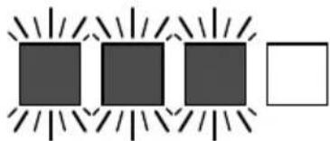
natural_image
Simple diagram with three dark squares surrounded by radiating lines and a single white square (no text or symbols)3901BA041 KN
natural_image
Line drawing of hands operating a STIHL TSA 230 tool on a cutting board (no text or symbols on the diagram itself)natural_image
Illustration of a person using a STIHL 754 2.00 angle grinder on a cutting tool (no text or symbols on the diagram itself)natural_image
Technical line drawing of a mechanical component embedded in a textured surface (no text or symbols)natural_image
Technical line drawing of a mechanical tool cutting through a circular component (no text or symbols)natural_image
Technical illustration of a hand using a tool to cut a circular component, no text or symbols presentnatural_image
Technical illustration of a person using a power saw to cut a circular component (no text or symbols on the diagram itself)natural_image
Technical line drawing of a mechanical tool cutting a circular component, with no visible text or symbolsnatural_image
Technical line drawing of a mechanical component with two protruding pins (no text or symbols)natural_image
Technical line drawing of a mechanical assembly with hands operating a tool, featuring a circular component (no text or symbols)natural_image
Line drawing of hands operating a STIHL TSA 230磨床 (no text or symbols on the diagram itself)natural_image
Illustration of hands using a STIHL TSA 200 angle grinder on a cutting tool (no text or symbols on the diagram itself)natural_image
Technical line drawing of a mechanical component embedded in a textured surface (no text or symbols)natural_image
Technical illustration of a hand using a cutting tool to cut a circular component (no text or symbols present)natural_image
Technical illustration of a hand using a tool to cut a circular component, no text or symbols presentnatural_image
Illustration of a hand using a saw to cut a circular component, no text or symbols presentnatural_image
Technical line drawing of a mechanical tool cutting a circular component, with no visible text or symbolsnatural_image
Technical illustration of a mechanical assembly with hands operating a tool and a circular component, no text or symbols present.natural_image
Technical line drawing of a mechanical component with two protruding pins (no text or symbols)180BA001 KN
natural_image
Four identical dark gray squares arranged horizontally with radiating lines, no text or symbols present.C

D
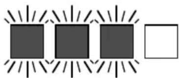
natural_image
Simple diagram with three dark squares surrounded by radiating lines and a white square (no text or symbols)3901BA041 KN
Supply of Machinery (Safety) Regulations 2008,
Electromagnetic Compatibility Regulations 2016
und The Restriction of the Use of Certain
Hazardous Substances in Electrical and
natural_image
Line drawing of hands using a STIHL TSA 230 power cutter on a cutting machine (no text or symbols on the diagram itself)natural_image
Illustration of hands using a STIHL 734-230 power tool to cut a circular component (no text or symbols on the diagram itself)natural_image
Technical line drawing of a mechanical component embedded in a textured surface (no text or symbols)natural_image
Technical line drawing of a lathe machining a circular component (no text or symbols)natural_image
Technical illustration of a hand using a tool to cut a circular component (no text or symbols present)natural_image
Technical line drawing of a cutting tool with a circular cutter and a flat blade, no text or symbols presentnatural_image
Technical illustration of a cutting tool and a circular component, no text or symbols presentnatural_image
Technical illustration of a mechanical assembly with hands operating a tool and a circular component, no text or symbols present.natural_image
Technical line drawing of a mechanical component with no visible text or symbols0458-707-9821-C
- Inhaltsverzeichnis
- Guide to Using this Manual
- Pictograms
- Symbols in text
- WARNING
- NOTICE
- Engineering improvements
- Safety Precautions
- General compliance
- Intended use
- Clothing and equipment
- Transport
- Cleaning
- Accessories
- Depth stop with suction support
- Safety Precautions English
- Drive
- Battery
- Battery charger
- Cut-off machine, spindle bearing
- Abrasive cutting wheels
- Selecting the abrasive cutting wheels
- Fitting abrasive cutting wheels
- Storing abrasive cutting wheels
- Before starting work
- Switching on the machine
- During operation
- After finishing work
- Storage
- Vibrations
- Maintenance and repairs
- Reactive Forces
- Kickback
- Working Techniques English
- Pulling away
- Working Techniques
- Cutting
- Sample Applications
- Water attachment
- Water must always be used for wet cutting when working with diamond abrasive cutting wheels
- Extend service life and increase cutting speed
- Binding dust
- Use composite resin abrasive cutting wheels with or without water – depending on version
- Composite resin abrasive cutting wheels suitable only for dry cutting
- Sample Applications English
- Composite resin abrasive cutting
- Observe with diamond and composite resin abrasive cutting wheels
- Objects to be cut
- Severed parts
- Cut in several passes
- Cutting plates
- Cutting pipes, round and hollow bodies
- Cutting concrete pipe
- Concrete pipe – cut recess
- Cutting Wheels
- Transport and storage
- Diamond Abrasive Wheels English
- Product Codes
- Troubleshooting
- Abrasive wheel
- Axial and radial run-out
- Undercut
- Built-up edges, sharpen
- Mounting an Abrasive Wheel
- Removing an abrasive wheel
- Fitting an abrasive wheel
- Connecting Charger to Power Supply
- Charging the Battery
- AL 300, AL 500 Chargers
- AL 100 Charger
- End of Charge
- LEDs on Battery
- During charging
- During Operation
- If the red LEDs glow continuously / flash
- Green continuous light ...
- Red flashing light ...
- Connecting the water supply
- Switching On
- Inserting the battery
- Switching on the machine
- Switching Off
- Removing the battery
- Storing the Machine
- Battery compartment cover (special accessory)
- Battery storage
- Storing the charger
- Minimize Wear and Avoid Damage
- Maintenance Work
- Wear parts
- Machine no.
- Specifications
- Battery
- Abrasive wheels
- Weight
- Water supply
- Sound and vibration levels
- Values when cutting concrete under pressure with diamond abrasive wheel
- Values when maximum engine speed without load with diamond abrasive wheel
- Values when maximum engine speed without load with composite resin abrasive wheel
- Transporting
- Troubleshooting English
- REACH
- Maintenance and Repairs
- Disposal
- EC Declaration of Con- formity
- UKCA Declaration of Conformity
- UK CA
- General Power Tool Safety Warnings
- 1) Work area safety
- 2) Electrical safety
- 3) Personal safety
- 4) Power tool use and care
- 5) Battery tool use and care
- 6) Service
- 7) Safety instructions for abrasive wheel applications
- Safety instructions for cut-off machines
- 8) Additional safety instructions for abrasive wheel applications
- Kickback and associated safety instructions
- Índice
- Vinkelslip, spindellagring
- Märkäleikkaus
- Nedves használathoz
Brand : STIHL
Model : TSA 230
Category : Grinder