
Smart Videohub - Router Blackmagic Design - Free user manual and instructions
Find the device manual for free Smart Videohub Blackmagic Design in PDF.


| Product Type | Professional SDI router with integrated control panel |
| Available Models | Smart Videohub 12x12, 20x20, 40x40, Smart Videohub CleanSwitch 12x12 |
| Video Connectivity | SDI inputs and outputs (BNC): automatic detection of SD, HD, 3G-SDI, 6G-SDI and 12G-SDI depending on model |
| Reference | Reference input (black burst or tri-level) for synchronization |
| Control | Front panel with LCD screen, scroll wheel, SRC/Dest/Take/Clear buttons; remote control via Ethernet (Videohub Control) or hardware panels |
| Network | RJ45 Ethernet port (10/100/1000) for IP control; USB 2.0 port for configuration and updates |
| Supported Video Formats | SD, HD (720p, 1080i, 1080p), 2K, Ultra HD (2160p) depending on model; simultaneous DVB-ASI routing |
| Power | Universal AC power supply 100-240V, 50/60 Hz; typical consumption depends on model |
| Rack Mounting | Standard rack format (1U for 12x12 and CleanSwitch, 2U for 20x20 and 40x40) |
| Maintenance | External cleaning with a soft, dry cloth; ensure free ventilation |
| Safety | Mandatory grounding; do not expose to moisture; disconnect before servicing |
| Spare Parts and Repairability | Tool-less replaceable fan (some models); no user-serviceable parts; contact Blackmagic Design support |
| Included Software | Blackmagic Videohub Control, Setup and Hardware Panel Setup for Mac and Windows |
| Warranty | 36 months (unit); 12 months (connectors, cables, fans) |
Frequently Asked Questions - Smart Videohub Blackmagic Design
User questions about Smart Videohub Blackmagic Design
0 question about this device. Answer the ones you know or ask your own.
Ask a new question about this device
Download the instructions for your Router in PDF format for free! Find your manual Smart Videohub - Blackmagic Design and take your electronic device back in hand. On this page are published all the documents necessary for the use of your device. Smart Videohub by Blackmagic Design.
USER MANUAL Smart Videohub Blackmagic Design
Installation and Operation Manual
Videohub
February 2020
English, 日本語, Français, Deutsch, Español, 中文, 한국어, Русский, Italiano, Português and Türkçe.
Languages
To go directly to your preferred language, simply click on the hyperlinks listed in the contents below.
English 3
日本語 94
Français 175
Deutsch 256
Español 337
中文 418
한국어 499
Русский 580
Italiano 661
Português 742
Türkçe 834
Developer Information 916

natural_image
Circular portrait photo of a smiling man in a dark shirt against a gray background (no text or symbols)Welcome
Thank you for purchasing Videohub!
We hope you share our dream for the television industry to become truly creative by allowing anyone to have access to the highest quality video.
Previously, high end television and post production required investing in millions of dollars of hardware, and professional SDI routers have always been way too costly for most people to afford. HD-SDI is even more expensive and, until now, only the largest post production and television facilities could afford HD-SDI routing. Videohub changes all that! Some Videohub models not only give you HD-SDI, but also the latest Ultra HD format, enabling you to pipe 4K video around your studio.
This instruction manual contains all the information you'll need to install your Videohub, although it's always a good idea to ask a technical assistant for help if you are not sure what IP addresses are, or if you don't know much about computer networks. Videohub is easy to install, however there are a few slightly technical preferences you will need to set after you install it.
Please check our web site at www.blackmagicdesign.com and click the support page to download the latest updates to this manual and Videohub software. Lastly, please register your Videohub when downloading software updates so we can keep you updated when new software is released. We are constantly working on new features and improvements, so we would love to hear from you!
We hope you get years of use from your Videohub and have lots of fun connecting everyone in your facility together!
Grant Petty
Grant Petty
CEO Blackmagic Design
Contents
Videohub
Getting Started 5 Universal Videohub 72 33
Getting Started with Videohub 5 Building Universal Videohub 72 34
Plugging in Video 5 SDI Interface Card 38
Controlling your Videohub 5 Universal Videohub Interface Cards 39
Blackmagic Videohub Software 6 Universal Videohub Deck Control Cable 40
Smart Videohub CleanSwitch 12x12 6 3G-SDI Videohub Routers 40
Connecting Videohub to a Network 6 Blackmagic 3G-SDI Videohub Routers 40
Connect to an Ethernet Network 6 Using the Smart Videohub Control Panel 42
Connect to a Videohub Server with USB 7 Videohub Router Monitoring 43
Configuring your Videohub Server Settings 8 Router Monitoring with
Configuring Network Settings Blackmagic Multiview 16 43
with a Built In Control Panel 10 Using the Built in Control Panel and LCD 43
Smart Videohub Control Panel 10 Blackmagic Videohub Software 46
Using the Smart Videohub To install your Blackmagic
Control Panel and LCD 10 Videohub software 46
Switching Routes with Smart Videohub 11 Blackmagic Videohub Setup 47
Videohub Hardware Control Panels 13 Blackmagic Videohub Control 51
Introducing Videohub Hardware Videohub Hardware Panel Setup 63
Control Panels 13 Configuring Videohub Master Control Pro 66
GPI and Tally Interface 14 Configuring Videohub Smart Control Pro 67
Connecting USB to Configure the Controlling Blackmagic MultiView
Control Panel 14 16 with Videohub Software 73
Plugging into an Ethernet Network 15 Developer Information 75
Control Panel Button Diagnostics 16 Blackmagic Videohub Ethernet
Updating the Software in your Protocol v2.3 75
Videohub Controller 17 Videohub RS-422 Protocol 81
About Routing Levels 17 Saving and Loading Labels with
How to Select Sources and Destinations 18 Telnet in Mac OS 84
Using Videohub Smart Saving and Loading Labels with
Control Pro as a Cut-Bus Controller 24 Telnet in Windows 85
Using Videohub Smart Help 87
Control Pro as an XY Controller 24 Replacing a fan in Universal Videohub 87
Labeling Pushbuttons 25 Replacing the fan in Broadcast Videohub 88
Universal Videohub Routers 26 Regulatory Notices 91
Universal Videohub 288 26 Safety Information 92
Building Universal Videohub 288 28 Warranty 93
Getting Started
Getting Started with Videohub
Getting started with Videohub is as simple as connecting power and plugging in your video sources and destination equipment. Your Videohub can be controlled using the powerful Videohub Control software, hardware control panel or front panel for some models.
Creating an IP Videohub with Teranex Mini IP Video 12G
If you are looking for information on the creation of an IP Videohub for routing Blackmagic Teranex Mini IP Video 12G units, refer to the Teranex Mini IP Video 12G manual which can be downloaded from www.blackmagicdesign.com/support.
Plugging in Video
To plug in your video sources:
1 Connect your video sources to the SDI inputs on the rear panel of your Videohub.
2 Connect your destination equipment to the SDI outputs on the rear panel of your Videohub.
Your Videohub's SDI connections will auto detect all supported video formats.

Connect your sources and destination equipment to your Videohub's SDI inputs and outputs.
Controlling your Videohub
There are two ways to control your Videohub:
1 Connect your Videohub to your computer via Ethernet and use the intuitive Videohub Control software to control your Videohub. For more details refer to the 'connecting Videohub to a network' section in this manual.
2 Control your Videohub using a hardware control panel, either built in or external depending on the model.
For example, Smart Videohub models have a built in control panel, LCD and rotary knob for making fast routing changes directly from your Videohub router. For more details, see the 'switching routers with Smart Videohub' section in this manual.

Routing changes can be done directly with the Smart Videohub models.
Blackmagic Videohub Software
'Blackmagic Videohub Control' is one of the three Blackmagic Videohub software applications. Also included are 'Blackmagic Videohub Setup' and 'Blackmagic Videohub Hardware Panel Setup' that are used for configuring settings and updating internal software.
For Videohub software installation instructions, see the 'Blackmagic Videohub software' section.
Using Blackmagic Videohub Setup, you can customize your source and destination labels so you can easily identify them. Refer to the 'Blackmagic Videohub setup' section to learn more about customizing labels.
Smart Videohub CleanSwitch 12x12
When you need to cleanly switch between video sources to monitors or directly to air, you will need timed or genlocked signals. If you cannot guarantee perfectly timed source signals but you still need to clean switch, then you can use Smart Videohub CleanSwitch 12x12 as this model features resynchronization on all inputs so you get perfect clean feeds.
Smart Videohub CleanSwitch 12x12 includes full resynchronization on every input so the router automatically re times all inputs to ensure clean, glitch free switching between router cross points. Sources of the same resolutions and the same frame rate can even be output directly to air for smooth, cuts only production. The Smart Videohub CleanSwitch 12x12 will lock to the reference input or to Input 1 if no reference signal is connected. The video format of the reference signal and all inputs need to be identical for glitch free switching. You can still switch between mixed video formats, however they will not be synced.
Connecting Videohub to a Network
Connect to an Ethernet Network
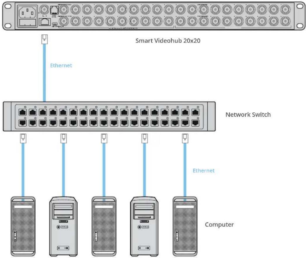
Many Videohub models have an Ethernet port and can connect directly to your Ethernet network switch or a computer on your local area IP based network.
To connect Videohub to a network:
1 Securely connect and power on all of the power supplies included with your Videohub.
2 Connect your Videohub router to the network switch or computer Ethernet port with a standard RJ45 Ethernet cable.
If you have a Universal Videohub 288 populated with two Crosspoint Cards, connect Ethernet cables to both for network failover redundancy. Your Universal Videohub 288 will have a single IP address, despite having two Ethernet connections to the network switch.
For Smart Videohub models with a built in control panel, you can use the rotary knob and buttons to configure IP address and network settings, or use Blackmagic Videohub Setup. For models without a front control panel, set your network settings using Blackmagic Videohub Setup.
Refer to the Blackmagic Videohub Setup section of this manual for more information. Network settings adjustments using Blackmagic Videohub Setup can only be adjusted when connected to your Videohub via USB.
Smart Videohub 20x20 connecting to an Ethernet Network
Connect to a Videohub Server with USB
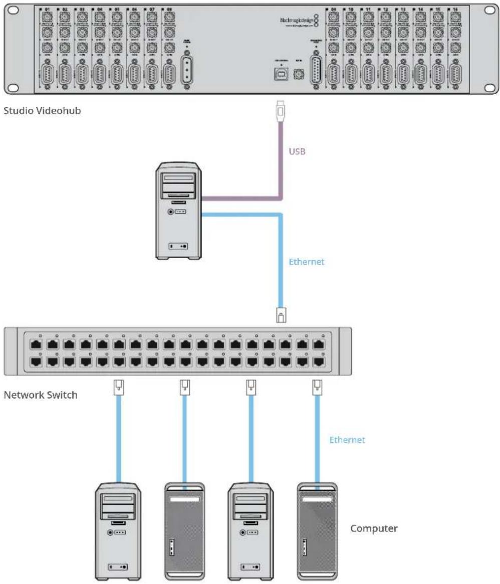
Non ethernet enabled Videohubs can connect to any computer on your local area IP based network via USB. One “server” computer on your network connects to Videohub via the plug and play USB connection, and shares the Videohub with other computers and iPads on your network in a similar way to USB printer sharing. You don’t need a dedicated or powerful computer for this task.
The Videohub Server can be any computer running Mac OS or Windows. Any number of Mac and Windows clients can connect to the server over the network.
To connect Videohub to the local area IP based network:
1 Securely connect and power on all of the power supplies included with your Videohub.
2 Connect the Videohub router to the Videohub Server computer with a standard USB 2.0 type A-B male cable.
3 Connect the Videohub Server computer to your network switch. We strongly recommend connecting the Videohub Server computer with reliable Ethernet cables in preference to wireless networking. Wireless networking may be affected by interference from appliances and other wireless devices.
Proceed to the "Configuring your Videohub Server Settings" section.
Studio Videohub connecting to a server via USB
flowchart
graph TD
    A["Studio Videohub"] -->|USB| B["Server"]
    A -->|Ethernet| C["Network Switch"]
    C --> D["Computer"]
    style A fill:#f9f,stroke:#333
    style B fill:#ccf,stroke:#333
    style C fill:#cfc,stroke:#333
    style D fill:#fcc,stroke:#333
Configuring your Videohub Server Settings
If you will be using Ethernet to connect to your Videohub, refer to the "Blackmagic Videohub Setup" section in this manual.
Videohubs without Ethernet are connected to a computer via USB and other control panels can see the Videohub by looking for this computer. It effectively becomes a "server", that all the other control panels on the network can connect to.
A Videohub "server" needs a static IP address and your network administrator will probably want to configure this for you. Please follow the steps below for your respective operating system.
Mac OS
1 Go to System Preferences
2 Click on Network
3 Check the IP address in the configuration information for your Ethernet or Airport network.
4 Set the network configuration to either Using DHCP with manual address or Manually.
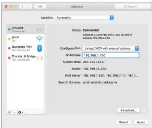
Network Preferences in Mac OS set to "Using DHCP with manual address" to provide a static IP address.
Windows
1 Open Control Panel
2 Click on the Network and Sharing Center.
3 In the panel on the left, click Change Adapter Settings.
4 Right click on your Ethernet connection, click on Properties and Select Internet Protocol Version 4 (TCP/IPv4).
5 Click the Properties button and select 'Use the following IP address'.
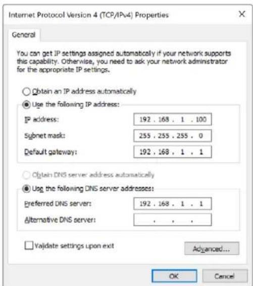
Network control panel in Windows set to 'Use the following IP address' to provide a static IP address.
Configuring Network Settings with a Built In Control Panel
You can use Smart Videohub models' built in control panel and LCD to configure network settings. Your router will be visible to other computers and hardware panels and these devices can then control the unit remotely and make the routing changes. If your router does not have a front panel control, then you should use Blackmagic Videohub Setup to configure your Videohub's network settings. Refer to the 'Blackmagic Videohub Setup' section for more information.
To set the IP address using the front control panel:
1 Press the 'menu' button to open the 'settings' menu.
2 Use the rotary knob to scroll down to 'network' settings. The 'take' button will flash. Press the 'take' button to confirm the selection.
3 Rotate the knob to select the entry you want to change and press 'take' to confirm.
4 Use the rotary knob to change a number field. Press the 'take' button to confirm the change and move through the fields.
5 Make sure you confirm the last change by pressing the 'take' button. You will know your settings are confirmed when the field entries are no longer highlighted.
6 Press the 'menu' button to exit the settings menu and return to your source and destination status.
If required, the subnet and gateway address can be set by the same method.
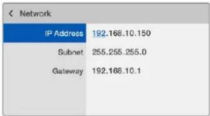
Press MENU to enter the network page and use the TAKE button and rotary knob to set the IP address.
Smart Videohub Control Panel
Using the Smart Videohub Control Panel and LCD
Smart Videohub routers include Blackmagic Smart Videohub 12x12, 20x20 and 40x40, plus Smart Videohub CleanSwitch 12x12. These models feature a built in control panel and LCD. Routing changes can be made without a computer by pressing the numbered pushbuttons on the front control panel. Remote router control can also be used.

Menu buttons on Smart Videohub 40x40
Menu Buttons Explained

MENU
Switches between the routing display and the network configuration page.

VIDEO
Use this button in conjunction with the 'src' and 'dest' buttons to display either the source or destination video on the LCD.

SRC
Press this button and then a numbered pushbutton to select your source.

DEST
Press this button and then a numbered pushbutton to select your destination.

CLEAR
Press this button to discard a route change.

TAKE
Press this button to confirm a route change.
Switching Routes with Smart Videohub
Switching routes with your Blackmagic Smart Videohub can be done easily using the integrated front panel.
1 Select your destination by pressing the 'dest' button and pressing a numbered pushbutton. Alternatively, you can use the rotary knob to scroll alphabetically through the destination labels. The corresponding numbered button will light to indicate the port number.
2 Select the source by pressing the 'src' button and pressing a numbered pushbutton. Alternatively, you can scroll through the source labels.
3 When you have selected a destination and source, the 'take' button will flash red until you have pressed it to confirm your route. The 'clear' button will also flash, indicating that you can cancel your route change by pressing the 'clear' button.
Selecting the Cut Bus Feature
Smart Videohub models provide two different routing modes for switching sources to destinations. By default, your Smart Videohub model is set to use the 'take' button when switching routes. Using this mode, you simply press the 'take' button to confirm a selected source for a chosen destination.
If you want a faster way to switch routes, you can use the cut bus mode. In cut bus mode, simply select your destination, then press the numbered source pushbuttons or turn the rotary knob to instantly switch routes. This feature is very effective if you need to use Smart Videohub CleanSwitch 12x12 as a standby switcher in a live switching environment.
To select between cut bus and take button modes:
1 Press the 'menu' button to open the settings menu and use the rotary knob to select the 'use take' setting. Press the 'take' button to confirm the selection.
2 Using the rotary knob, select 'on'. This sets your Videohub to use the take button to confirm routing changes. To select cut bus mode, select 'off'. This means when you select a source, it will be immediately routed without needing confirmation via the take button.
3 Press 'take' to confirm the settings change. Press the 'menu' button to return to your source and destination status.
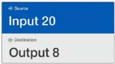
The LCD provides instant confirmation of route selections and changes and allows you to preview source and destination video without an external monitor.
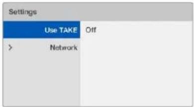
The Smart Videohub menu screen above shows the 'use take' setting set to 'off'. This enables cut bus routing which lets you bypass the take button and route your sources instantly using the source buttons or rotary knob.
Locking and unlocking routes on Smart Videohub
Locking and unlocking routes with your Blackmagic Smart Videohub can be done easily using the integrated front panel.
To lock a Destination
1 Press the 'dest' button
2 Hold the 'dest' button for 2 seconds. A padlock will appear next to the label to indicate that the destination is now locked.
To unlock a Destination
1 Press the 'dest' button
2 Hold the 'dest' button for 2 seconds. The padlock will disappear from the label bar, which indicates that the destination is now unlocked.
If a locked destination is selected, the 'src' button will no longer select a source.
Videohub Hardware Control Panels
Introducing Videohub Hardware Control Panels
Videohub Master Control Pro
Videohub Master Control Pro is a 1 rack unit mountable control panel with 36 backlit pushbuttons, LCD, scroll wheel and Ethernet connectivity designed to perform Videohub crosspoint switching without using a computer. Videohub Master Control Pro can control all sources and destinations for any size of Videohub router, as well as RS-422 deck control.
Videohub Master Control Pro uses port labels to aid in fast selection of equipment using software. Pushbuttons can be configured and labeled to provide fast selection of common equipment types, e.g., cameras, decks and monitors. It also includes a loop through Ethernet port for connecting to additional control panels, Videohub routers or other network devices. Macro buttons illuminate green when enabled and each one can be configured to perform up to 16 simultaneous crosspoint switches.
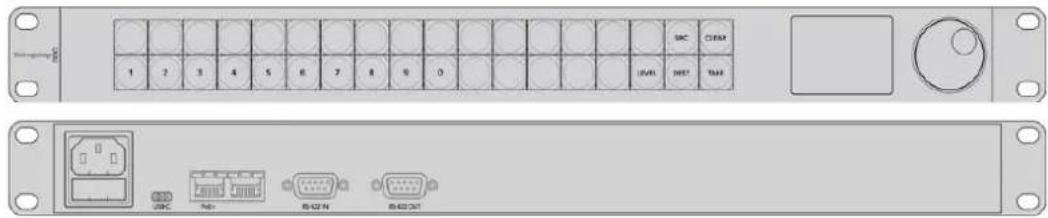
Videohub Master Control Pro
Videohub Smart Control Pro
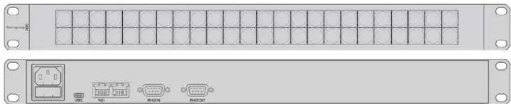
Videohub Smart Control Pro is a 1 rack unit mountable control panel with 48 backlit pushbuttons and Ethernet connectivity, which works with all models of Videohub. It can be configured to work with one or many SDI destination devices. Once configured for your SDI equipment and Videohub router, Videohub Smart Control Pro no longer requires a computer and can immediately change SDI routes as desired.
When configured for a single SDI destination, such as a monitor or deck, the pushbuttons can instantly switch between 48 different SDI sources on the same Videohub router. When configured for multiple SDI destinations, destination buttons become gold, source buttons become white and the lower right button can be configured as a take button and illuminates red. Macro buttons illuminate green when enabled and each one can be configured to perform up to 16 simultaneous crosspoint switches.
natural_image
Front and back view of a server rack unit with front panel, internal connectors, and terminal ports (no text or symbols visible)Videohub Smart Control Pro
GPI and Tally Interface
GPI and Tally Interface is a low cost alternative for multi-camera productions where a camera control unit, or CCU, operator needs to switch video from one of several cameras being controlled to a single monitor. It features 8 configurable GPIs and 8 configurable GPOs.
The GPIs send commands to your Videohub by ethernet to switch the selected camera to the operator's monitor under certain crosspoint conditions. The GPOs send a tally signal to your cameras or other devices under certain crosspoint conditions.

GPI and Tally Interface
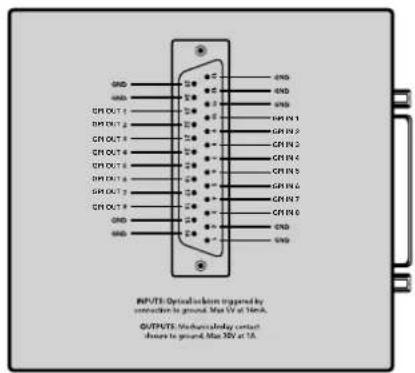
Pinout diagram of the DB25 connector
Refer to the pinout diagram on the back of the unit when fabricating your custom cable.
For information on how to configure your GPI and Tally Interface using Blackmagic Videohub Setup, refer to the 'Blackmagic Videohub Software' section of this manual.
Connecting USB to Configure the Control Panel
A USB connection to a computer is used to configure the network settings of the Videohub Controller.

Rear view of Videohub Smart Control showing the USB port.
Plugging into an Ethernet Network
In most facilities, Videohub is usually shared via an Ethernet network switch so it can be controlled by computers on the network as well as by Videohub control panels.
Videohub Master Control and Videohub Smart Control
Videohub Master Control and Videohub Smart Control connect to any Videohub via standard Ethernet networking and can be powered over Ethernet or with an external power supply.
If your Ethernet switch does not provide power over Ethernet, use the included universal power supply.
To connect a Videohub control panel to the local area IP based network:
1 Connect the included power supply to your Videohub control panel. You can skip this step if your network switch provides power over Ethernet. No problem will be caused by connecting the power supply and power over Ethernet at the same time.
2 Use the network In port on your Videohub control panel to connect to your network switch with a standard RJ45 Ethernet cable.
3 You might also wish to connect another network device to the network Out port on your Videohub control panel, such as a Videohub router, another Videohub control panel or other network devices such as a computer or VoIP phone. The Out port does not provide power over Ethernet and any network device connected to this port will require its own power supply.
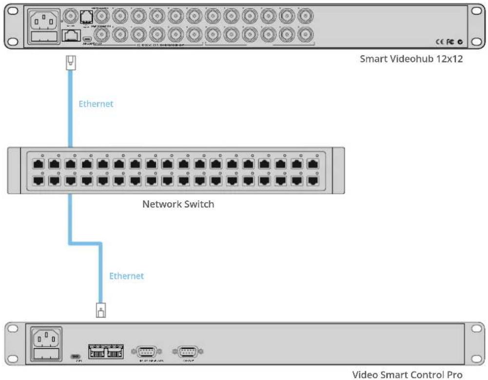
Videohub Smart Control Pro connected to a Smart Videohub 12x12 via an Ethernet Network Switch.
Control Panel Button Diagnostics
When power is first connected to a Videohub control panel, all the buttons will display their test lights in the following sequence: red, green, blue and white. The top left button of a Videohub control panel indicates its network status, using the following diagnostic display:
Pink flashing light
Unit is attempting to acquire an IP address. The button should quickly become red if the unit is set to use a static IP address, or if the unit successfully acquires an IP address from the DHCP server.

Videohub control panel is attempting to acquire an IP address.
Red flashing light
Unit has acquired an IP address and is attempting to connect to the Videohub Server. Make sure the Videohub or Videohub Server computer is powered on and connected via Ethernet.

IP address has been acquired and control panel is attempting to connect to the Videohub Server.
Yellow flashing light
Unit has connected to a Videohub Server computer but the Videohub Server is running an incompatible software or firmware version. Update Videohub with the latest version of the Videohub software and firmware and then power cycle the Videohub control panel.

Videohub Server is running an incompatible software or firmware version.
No flashing light
Unit has successfully connected to the Videohub Server and is ready to control the Videohub if solid white, or solid white and gold, lights can be seen.

Control panel has successfully connected to the Videohub Server.
If the top left button took several minutes to turn red, the unit has failed to acquire an IP address and has eventually provided itself with a self-assigned AutoIP address in the 169.254.xxx.xxx format. Unless you wish to use an AutoIP address, disconnect and firmly reconnect the network cables to ensure they are properly connected, check for faulty network cables and make sure the DHCP server has spare IP addresses available. Unplug and reconnect all power sources from the Videohub control panel so it will request a new IP address from the DHCP server. The button should quickly become red. The unit will only perform these diagnostics when it is not selected in Videohub Hardware Panel Setup software.
Updating the Software in your Videohub Controller
Follow these steps to check if your Videohub control panel's internal software is up to date:
1 Connect your Videohub control panel to the computer via USB.
2 Launch the Blackmagic Videohub Hardware Panel Setup.
3 If a software update is required, a message will appear asking if you would like to update your Videohub control panel. Click Yes. The update will take about 2 minutes to complete.
4 The message "Software Update Complete" should appear at completion of the update. Click OK to dismiss the message. Settings can be changed now if desired and this is a good opportunity to give each Videohub control panel a unique name.
5 You can now unplug the USB cable from your Videohub control panel.
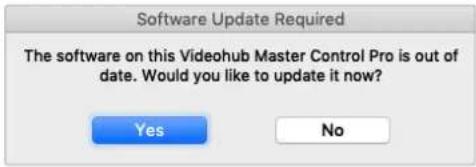
This message will appear if an internal software update is required.
About Routing Levels
If your Videohub does not feature RS-422 remote deck control, Videohub Master Control will always show "SDI" on its LCD and you don't need to read anything more about routing levels.
If your Videohub does include RS-422 remote deck control ports, you can use the LEVEL button on Videohub Master Control to reduce the list of sources and destinations by routing level.
Start by pressing the DEST button. Now press the LEVEL button to cycle through the routing levels:
SDI 422
Choose this routing level to reduce the list of video equipment to devices with matching labels for their remote and SDI ports. This level is commonly used with SDI capture cards and VTR decks but cannot be used with cameras and monitors as they do not have RS-422 remote ports.
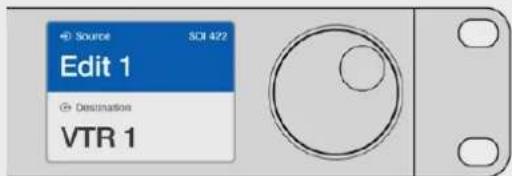
Choose the SDI 422 routing level if you only want to see SDI video equipment with RS-422 deck control. In this example, the capture card (Edit 1) and the deck (VTR 1) are listed because they both have SDI and RS-422 ports.
SDI
Lists all SDI sources and destinations. Choose this routing level if you want to see all SDI video equipment, i.e., cameras, monitors, capture cards and VTR decks, regardless of RS-422 connections.
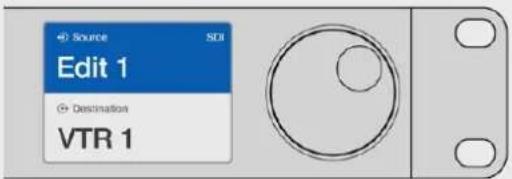
Choose the SDI routing level if you want to see all SDI video equipment. In this example, the capture card (Edit 1) and the deck (VTR 1) are listed because they both have SDI ports.
422
Choose this routing level if you want to reduce the list of video equipment to all devices with RS-422 deck control. This will list sources and destinations by the names of their RS-422 remote ports, regardless of whether there are any associated SDI ports and regardless of whether any associated SDI ports have matching labels or not. This level is commonly used with SDI capture cards and VTR decks but also lists remote control panels and servers used to control decks.
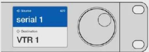
Choose the 422 routing level if you want to see all equipment with RS-422 remote deck control, including equipment with mismatched labels and also remote controllers. In this example, the capture card (Edit 1) has a mismatched label for its remote port (serial 1) and is only listed when the routing level is set to 422.

Front panel showing a new source has been selected.
How to Select Sources and Destinations
Videohub Master Control Pro provides several ways to select and switch your destinations and sources quickly, depending upon whether you have customized the port labels on your Videohub router or if you just want to enter port numbers directly.
Videohub Master Control Pro works in the same conceptual way as any other router control. These are the basic steps you will take, regardless of your method for selecting devices.
1 Press the DEST button to display a destination on the LCD. Use the pushbuttons and/or the scroll wheel to find the desired destination.
2 Press SRC and use the buttons and/or the scroll wheel to change the source connected to the destination.
3 Press TAKE to confirm the route change.
How to select devices by typing the Videohub port numbers
If you've chosen to keep the default labels for all Videohub SDI and remote ports, you can simply type the port numbers to make a routing change. This method is fast but requires that you remember port numbers or have devised a system for knowing what equipment is connected to each Videohub port.
1 Press the DEST button. The destination field will be highlighted blue on the LCD.
2 If your Videohub router has RS-422 remote control, press the LEVEL button until you have set the appropriate routing level for your equipment. Otherwise you can skip this step.
3 Type in the destination port number using the numeric pushbuttons. Each button will flash gold once as you press it. The destination will be displayed on the LCD. If you make a mistake, press the white CLEAR button and retype the port number.
4 Press the SRC button. The source field will be highlighted blue on the LCD.
5 Type in the source port number using the numeric pushbuttons. Each button will flash white once as you press it. The source will be displayed on the LCD. If you make a mistake, press the white CLEAR button and retype the port number.
6 The TAKE button will flash red, awaiting your confirmation of the route change. Press TAKE and the route will change immediately. Otherwise, press CLEAR and no route change will take place. Videohub Master Control returns to its idle state with the latest route displayed on the LCD.
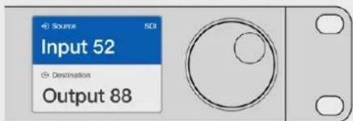
If you've chosen to keep the default labels for all Videohub SDI and remote ports, you can simply type the port numbers to make a routing change. In this example, press DEST and then type the port number 88. Then press SRC and type the port number 52. Press TAKE to confirm the route change.
How to select devices with the scroll wheel
Regardless of whether or not you've customized the Videohub port labels, you can always use the scroll wheel to browse through a list of sources and destinations. This is the slowest method but is useful if you want to see the list of all available equipment and ports.
1 Press the DEST button. The destination field will be highlighted blue on the LCD.
2 If your Videohub router has RS-422 remote control, press the LEVEL button until you have set the appropriate routing level for your equipment. Otherwise you can skip this step.
3 Scroll the wheel forwards or backwards until the desired destination is found. The destination will be displayed on the LCD.
4 Press the SRC button so it lights white. The source field will be highlighted blue on the LCD.
5 Scroll the wheel until the desired source is found. The source will be displayed on the LCD.
6 The TAKE button will flash red, awaiting your confirmation of the route change. Press TAKE and the route will change immediately. Or press CLEAR and no route change will take place. Videohub Master Control returns to its idle state with the latest route displayed on the LCD.
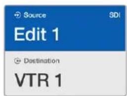
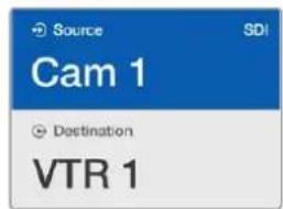
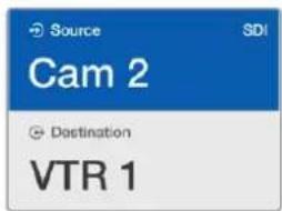
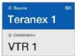
In this example, the scroll wheel is being used to list all sources that can be routed to the destination VTR 1, based upon the SDI routing level. When the scroll wheel is rotated, the names of source equipment are progressively displayed to make it very easy to find the desired video source.
How to select devices using the customizable buttons and scroll wheel
If you have customized the Videohub port labels, you can use the customizable buttons and scroll wheel together to find a short list of sources and destinations. This method is fast and intuitive because you only have to scroll through a short list of equipment and you don't have to remember any port numbers. This method is very helpful if you label types of equipment together by name, e.g., VTR, Cam and Mon.
1 Press the DEST button. The destination field will be highlighted blue on the LCD.
2 If your Videohub router has RS-422 remote control, press the LEVEL button until you have set the appropriate routing level for your equipment. Otherwise you can skip this step.
3 Press a button you have customized for a type of destination equipment, e.g., VTR. The button should light up gold.
4 Scroll the wheel forwards or backwards until the desired destination is found. In this example, the destination VTR will be displayed on the LCD. If you make a mistake, press the white CLEAR button and scroll until the correct destination is displayed.
5 Press the SRC button. The source field will be highlighted blue on the LCD.
6 Press a button you have customized for a type of source equipment, e.g., a capture card. The button should light up white.
7 Scroll the wheel forwards or backwards until the desired source is found. In this example, the source capture card will be displayed on the LCD. If you make a mistake, press the white CLEAR button and scroll until the correct destination is displayed.
8 The TAKE button will flash red, awaiting your confirmation of the route change. Press TAKE and the route will change immediately. Otherwise, press CLEAR and no route change will take place. Videohub Master Control will then return to its idle state with the latest route displayed on the LCD.
If any button you have customized for either a source or destination flashes but does not stay lit, Videohub Master Control is preventing you from selecting the button because the equipment type has not been labeled as a source or destination device or does not match the current routing level. For example, cameras should not usually be set as destination devices, monitors should not be set as source devices and won't match the RS-422 routing level. Refer back to Creating Button Labels in Configuring Videohub Master Control Pro for steps on how to change this.
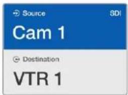
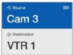
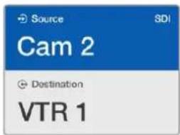
In this example, a customized Cam button has been selected so only cameras will be listed as sources, on the LCD, when the scroll wheel is rotated. This provides a fast way to find a video source because you only have to scroll through a short list of equipment.
How to select devices using the numeric buttons and scroll wheel
If you have customized the Videohub port labels with numbers, you can use the numeric buttons and scroll wheel together to find a short list of sources and destinations. This method is fast and intuitive because you only have to scroll through a short list of equipment and you don't have to remember any port numbers. This method is very helpful if you label groups of equipment together by numbers, perhaps to represent locations. For example, all the equipment in Studio 3 could be labeled VTR3, Edit 3, Cam 3A, Cam 3B, Mon 3A and Mon 3B etc.
1 Press the DEST button. The destination field will be highlighted blue on the LCD.
2 If your Videohub router has RS-422 remote control, press the LEVEL button until you have set the appropriate routing level for your equipment. Otherwise you can skip this step.
3 Using the numeric pushbuttons, type the destination number, e.g., 3 for Studio 3. Each numeric button will flash gold as you press it.
4 Scroll the wheel forwards or backwards until the desired destination is found. In this example, any of VTR 3, Edit 3, Mon 3A or Mon 3B could be displayed on the LCD. If you make a mistake, press the white CLEAR button and select another destination number.
5 Press the SRC button. The source field will be highlighted blue on the LCD.
6 Using the numeric pushbuttons, type the source number, e.g., 3 for Studio 3. Each numeric button will flash white as you press it.
7 Scroll the wheel forwards or backwards until the desired source is found. In this example, any of VTR 3, Edit 3, Cam 3A or Cam 3B could be displayed on the LCD. If you make a mistake, press the white CLEAR button and select another source number.
8 The TAKE button will flash red, awaiting your confirmation of the route change. Press TAKE and the route will change immediately. Otherwise, press CLEAR and no route change will take place. Videohub Master Control will then return to its idle state with the latest route displayed on the LCD.
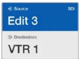
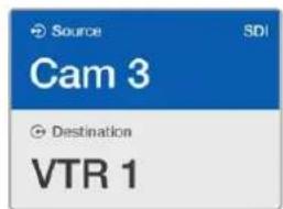
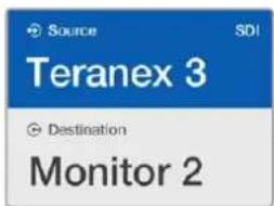
In this example, the numeric button "3" has been selected so only video sources with a "3" in their label will be listed, on the LCD, when the scroll wheel is rotated. This provides a fast way to find a video source because you only have to scroll through a short list of equipment based upon a group number, e.g. only list the equipment in Studio 3.
How to select devices using the customizable and numeric buttons together
If you have customized the Videohub port labels with names and numbers, you can use the customizable buttons and numeric buttons together to directly select sources and destinations. This method is very fast and intuitive because you don't have to scroll through a list of equipment and you only have to remember how many of each type of equipment you have, e.g., two VTRs and four monitors.
This method is very helpful if you label types of equipment by name and number, e.g., VTR 01, VTR 02, Cam 01, Cam 02, Cam 03, Mon 01, Mon 02, Mon 03 and Mon 04.
1 Press the DEST button. The destination field will be highlighted blue on the LCD.
2 If your Videohub router has RS-422 remote control, press the LEVEL button until you have set the appropriate routing level for your equipment. Otherwise you can skip this step.
3 Press a button you have customized for a type of destination equipment, e.g., VTR. The button should light gold.
4 Type in the destination equipment number using the numeric pushbuttons, e.g., 07 for VTR 07. Each numeric button will flash gold as you press it.
5 Press the SRC button. The source field will be highlighted blue on the LCD.
6 Press a button you have customized for a type of source equipment, e.g., a capture card. The button should light white.
7 Type in the source equipment number using the numeric pushbuttons, e.g., 03 for the capture card Edit 03. Each numeric button will flash white as you press it.
8 The TAKE button will flash red, awaiting your confirmation of the route change. Press TAKE and the route will change immediately. Otherwise, press CLEAR and no route change will take place. Videohub Master Control will then return to its idle state with the latest route displayed on the LCD.
If any button you have customized for either a source or destination flashes but does not stay lit, Videohub Master Control is preventing you from selecting the button because the equipment type has not been labeled as a source or destination device or does not match the current routing level. For example, cameras should not usually be set as destination devices, monitors should not be set as source devices and won't match the RS-422 routing level. Refer back to Creating Button Labels in Configuring Videohub Master Control Pro for steps on how to change this.
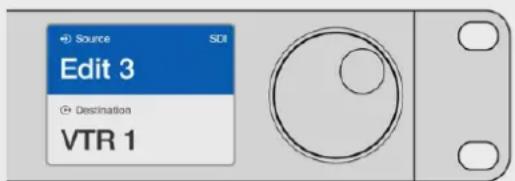
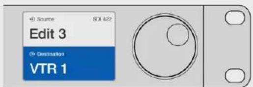
If you know that you want Edit 3 as the source, and VTR 1 as the destination, you can select the route directly without any scrolling being necessary. In this example, press DEST, press the customized VTR button and then press 1. VTR 1 will be shown in the destination field. Now press SRC, press the customized Edit button and then press 3. "Edit 3" will be shown in the source field. Finally, press TAKE to confirm the route change.
Locking and Unlocking Routes
To lock a destination using Videohub Master Control:
1 Set the destination and source using whichever method you prefer. Once the route has been set, Videohub Master Control will return to its idle state.
2 Press the DEST button. The destination field will highlight blue on the LCD.
3 If the desired route is not already displayed on the LCD, use the pushbuttons and/or scroll wheel to find the destination to be locked.
4 Press and hold the gold DEST button until a lock icon appears in the destination field of the LCD.
5 Press DEST again to return Videohub Master Control to its idle state and the destination field will revert to gray.
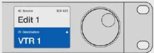
The destination field shows a lock icon if the destination is locked.
To unlock a destination using Videohub Master Control:
1 Press the DEST button. The destination field will highlight blue on the LCD.
2 If the desired route is not already displayed on the LCD, use the pushbuttons and/or scroll wheel to find the destination to be unlocked. The destination field will show a lock icon for the locked destination.
3 Press and hold the gold DEST button until the lock icon disappears from the destination field of the LCD.
4 Press DEST again to return Videohub Master Control to its idle state and the destination field will revert to gray.
The lock icon disappears from the destination field when the destination is unlocked.
Using Macros
If you press a green macro button, it will simultaneously make the crosspoint changes you have previously configured in Videohub Hardware Panel Setup. Each button can be configured with up to 16 crosspoint routes. If you have the Take button enabled, the simultaneous change of routes will only take place when you confirm by pressing the Take button. If for any reason the macro cannot be performed, the button will flash.
Using Videohub Smart Control Pro as a Cut-Bus Controller
If Videohub Smart Control Pro has been configured as a Cut-Bus controller, the destination device has already been chosen and you only need to choose a video source.
1 Select a white video source button. The button will light up to distinguish it from the other sources. The video source will immediately connect and be viewable on the destination device.
2 If the Take button has been enabled, the new source button and the Take button will flash. The route change will only take place when you confirm by pressing the Take button.

natural_image
Front panel of a dual-chamber electronic device with square slots and a highlighted red button (no text or symbols)Videohub Smart Control Pro configured as a Cut-Bus controller and with a Take button.
Using Videohub Smart Control Pro as an XY Controller
If Videohub Smart Control Pro has been configured as an XY controller, destination buttons light up gold and source buttons light up white. When working with multiple destinations, always select a destination button before selecting a source button.
To change routes:
1 Select a gold destination button and it will light up brightly to distinguish itself from the other destination buttons. If a video source has previously been connected to this destination, its button will light up white.
2 To connect a new source to the destination, press the desired video source button. The video source will immediately be connected and viewable on the destination device. The new source button will be brightly lit and the previous source button will dim to normal. To change another route, select another destination button and then select a new source button.
3 If the Take button has been enabled, the new source button and the Take button will flash. The route change will only take place when you confirm by pressing the Take button.
Locking and Unlocking Routes
To lock a destination, press and hold the desired destination button until it turns blue. The corresponding source button will illuminate. If you attempt to change sources for a locked destination, the destination button will flash blue. To unlock a destination, press and hold the button until it returns to the standard gold color.
Using Macros
If you press a green macro button, it will simultaneously make the crosspoint changes you have previously configured in Videohub Hardware Panel Setup. Each button can be configured with up to 16 crosspoint routes. If you have the Take button enabled, the simultaneous change of routes will only take place when you confirm by pressing the Take button. If for any reason the macro cannot be performed, the button will flash.

natural_image
Front panel of a rack-mounted device showing a grid of white and yellow buttons with one red button (no text or symbols)Videohub Smart Control Pro configured as an XY controller and with a Take button.
Labeling Pushbuttons
Videohub Master Control Pro and Videohub Smart Control Pro have removable pushbuttons that provide access for labeling.
Included with the software installer is a Videohub Control Labels folder containing a PDF template file. Fill out and print the PDF file labels. Then cut out the square labels so they are ready to be inserted into the buttons.
To remove the buttons:
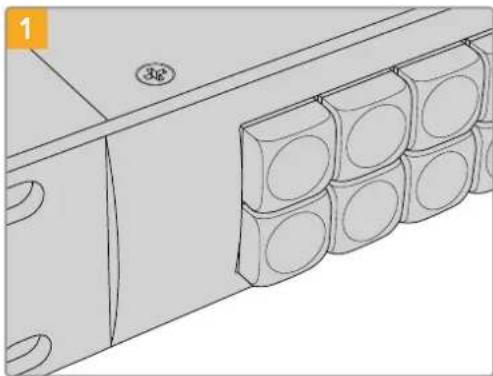
natural_image
Technical line drawing of a mechanical component with multiple cylindrical components and mounting holes (no text or symbols)Place your Videohub control panel on a desk or workbench.
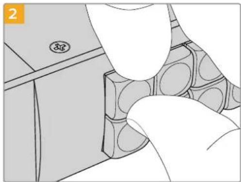
natural_image
Illustration of a hand inserting into a component with circular patterns, no text or symbols presentThe button keycaps can be easily removed by inserting your fingernail between the keycap and the button.
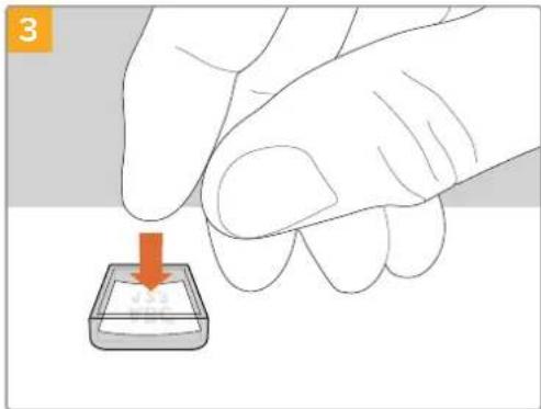
natural_image
Illustration of a hand pressing down on a small object with an orange arrow (no text or symbols)Loosely place your new printed label into the upturned clear keycap.
natural_image
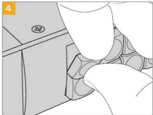
Illustration of a hand inserting a component into a mechanical housing (no text or symbols visible)Replace the keycap by aligning it onto the button and gently push until you feel it click into place.
Universal Videohub Routers
Universal Videohub 288
What you need to get started
Universal Videohub 288 is a large, modular router ideally suited to very large facilities and broadcasters. It features a 72 card rack frame that can be filled with any combination of BNC SDI or optical fiber SDI interface cards.
When fully populated with two Universal Videohub 288 Crosspoint cards, two power cards, 72 interface cards and 72 deck control cables, Universal Videohub 288 provides 288 SDI inputs, 288 SDI outputs, 288 bidirectional RS-422 deck control ports, reference input, redundant crosspoint processor, redundant Ethernet networking, redundant power and powerful Videohub routing control software for Mac and Windows.
Occasionally, the internal software of the Universal Videohub 288 will need to be updated. Videohub Setup will prompt you if an update is required. The utility uses the USB 2.0 connection and you will need to provide a USB 2.0 type A to mini B male cable.
Universal Videohub 288 ships as an empty rack frame, except for a removable fan tray and fans. All other hardware components, such as SDI interface cards and power supplies, must be purchased and installed separately. Read the following section to help you decide which components you will need before you build your Universal Videohub 288.
See the 'SDI Interface Card' and 'Universal Videohub Interface Cards' sections for more information on the different interface cards available for your Universal Videohub.
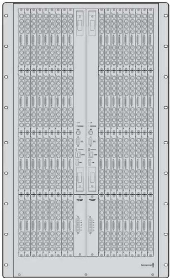
Universal Videohub 288
Universal Videohub 288 Crosspoint Card
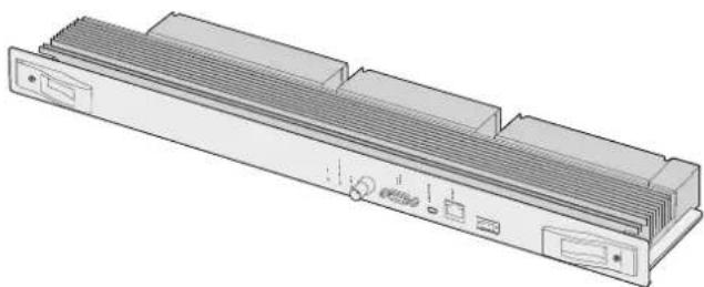
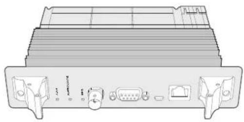
This module contains the crosspoint processor for switching video routes and changing deck control ports. Ethernet, USB and serial ports are located on the card for router control.
A Reference input is located on the card for connection to a tri-level sync or black burst genlock signal.
An Alarm light will illuminate on the card if user intervention is required, e.g., if inadequate cooling has caused Videohub to overheat. Alarm notification is supplied by the GPI (General Purpose Interface) output to other devices.
A Power Overload light will illuminate on the card if inadequate power is being supplied to the unit for the number of cards installed.
You will need a number 01 size Pozidriv screwdriver to install the Universal Videohub 288 Crosspoint card.
Router Control Cable
Remote router control is performed via 10/100Base-T Ethernet or serial. If router control is performed via Ethernet, the integrated Videohub Server is used. This means you only need to provide an Ethernet cable to connect Universal Videohub 288 to your Ethernet network switch.
Third party router controllers can control Universal Videohub 288 via Ethernet, or as an RS-422 slave device, for router crosspoint switching. Please refer to the Developer Information section of this manual for Videohub and RS-422 protocols.
Power Supply
When fully populated and running at maximum power consumption, Universal Videohub 288 can be powered by a single Universal Videohub Power Supply.
The Universal Videohub Power Supply package includes a power card with a single connection to a 1 RU size rack mount chassis which contains the power supply.
The Universal Videohub Power Supply chassis contains a universal power supply for use in all countries. You will need to provide a standard IEC cord with a C13 connector.
natural_image
3D technical illustration of a computer drive chassis with ventilation slots and ports (no text or symbols)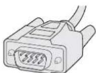
Universal Videohub 288 Crosspoint card Serial Cable
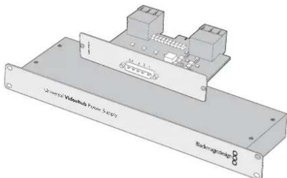
Universal Videohub Power Supply includes a power card, 1 RU chassis and connecting power cable.
Standard RJ45 Ethernet Cable
Building Universal Videohub 288
25 rack units of space should be reserved for the installation of Universal Videohub 288 and two rack mount power supply chassis, allowing free space for heat dissipation. Only 23 RU is required if Universal Videohub 288 is mounted at the top of an open rack as heat can be dissipated from the top.
Universal Videohub 288 is 18 RU high and 6 inches thick. You can rack mount Universal Videohub 288 facing forwards or reversed, or even mount it in the rear of the rack to leave space for other equipment.
Universal Videohub 288 contains electrostatic sensitive devices. It is essential to discharge yourself of static electricity before handling any of these devices, just as you would when installing devices into a computer. We recommend the use of an antistatic wrist strap when handling any of these devices.
Installing a Universal Videohub 288 Crosspoint Card
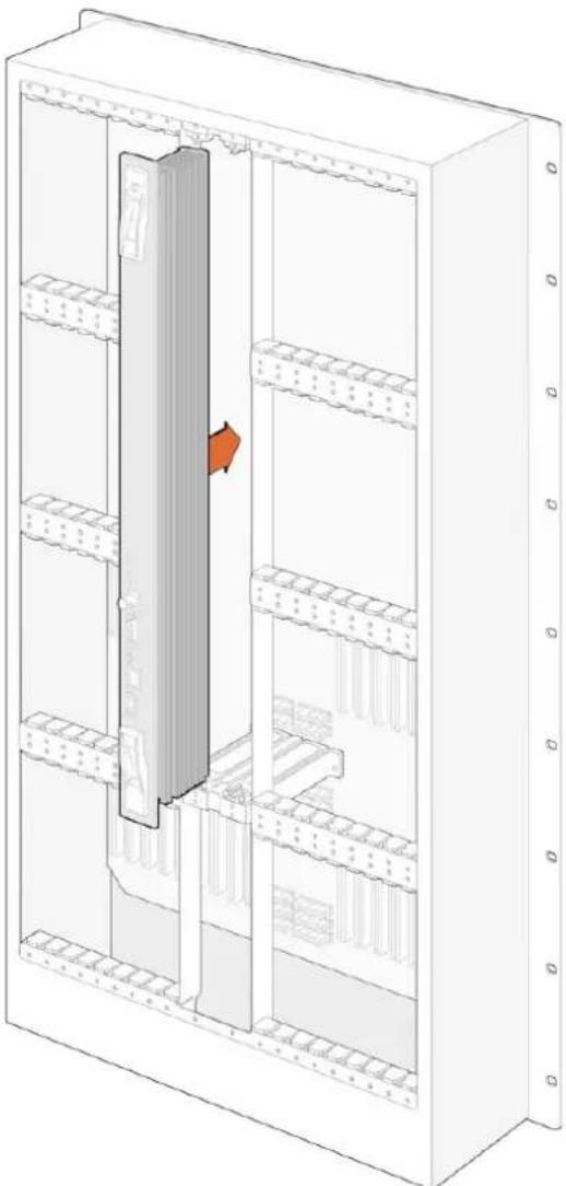
Now that your Universal Videohub 288 has been mounted in a rack, it needs to be fitted with a crosspoint card. The crosspoint card is the brains of Universal Videohub and performs video route and deck control switching. Universal Videohub 288 Crosspoint cards are hot-swappable, meaning they are designed to be installed and removed while the Universal Videohub is running.
natural_image
Technical line drawing of a multi-level storage unit with internal components and a highlighted section (no text or symbols)1 Hold the crosspoint card in a vertical orientation by its two levers. The BNC, Ethernet and other ports should be towards the bottom end of the card.
2 Gently insert the card into its slot, ensuring the top and bottom edges follow the black guides.
3 Firmly push both levers flat to fully engage the multi-pin connectors with the motherboard. Mating pins ensure that the card precisely engages with the motherboard without damaging the multi-pin connectors.
4 Use a number 01 size Pozidriv screwdriver to secure the two levers on the crosspoint card.
It is common to install a second crosspoint card for failover redundancy and we recommend doing this. If two crosspoint cards are installed, all video routes and port labels will be safely retained even if one card becomes faulty and has to be replaced. To remove the blanking plate from the right crosspoint card slot, you will need to use a number 02 size Pozidriv screwdriver.
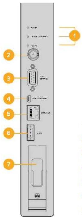
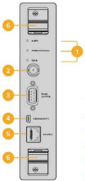
1 Status LED lights
2 Reference In
3 RS-422 router control
4 USB 2.0
5 Ethernet router control
6 Alarm GPI
7 Handle
Universal Videohub Status LEDs
The status LEDs marked 'alarm', 'power overload' and 'ref in' provide you with an indication of the current state of the Blackmagic Universal Videohub 288 Crosspoint. The following LED conditions provide specific information about the status of the unit.
| Red ‘alarm’ LED | ||
| Off No error. Normal operation. | ||
| On Error condition. Other error. Telnet into device to get error code. | ||
| 1 flash Error condition. Fan failure. | ||
| 3 flashes Error condition. No redundant power supply. | ||
Red 'power overload' LED
| [DBCT] | Off | Normal operation. Inactive / Slave mode. This should only be seen on a Blackmagic Universal Videohub 288 with 2 crosspoints. |
| [OWED] | Slowly blinking Normal operation. Active / Master mode. | |
| [COXC] | On Error condition. Power overload. Not enough power is being supplied. | |
White 'ref in' LED
| ○ | Off Normal operation. No reference connected. |
| ○ | On Normal operation. Reference connected. |
TIP Blackmagic Universal Videohub 288 Crosspoint has amber colored LEDs mounted inside the device that should only be visible when the heatsink is removed for development purposes. However, in some cases a dim amber light may be visible through the hole that has been drilled for the 'alarm' LED. This is not an error condition.
A healthy Universal Videohub 288 Crosspoint should display the following:
| Red ‘alarm’ LED Off. | ||
| Red ‘power overload’ LED Slowly blinking or off. | ||
| White ‘ref In’ LED Solid white or off. |
Installing Interface cards
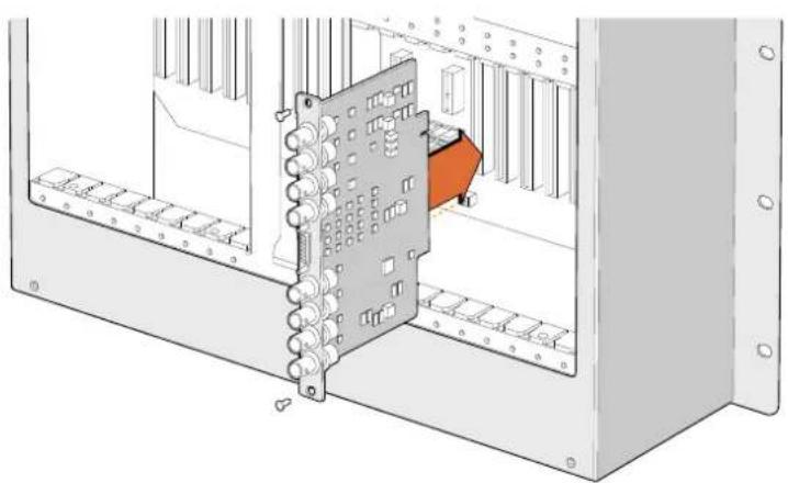
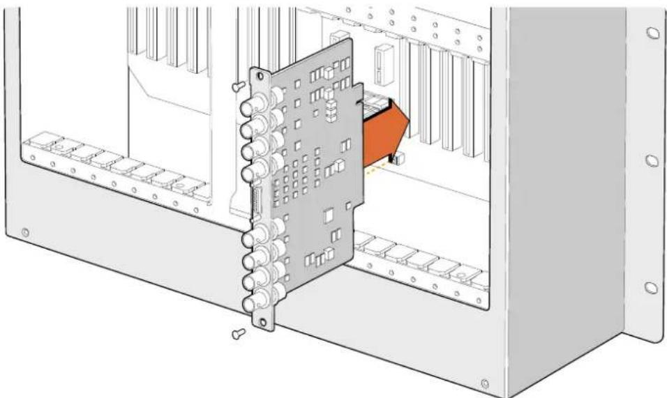
Installing a Universal Videohub SDI Interface or Universal Videohub Optical Interface is easy and the steps are the same for installing each type of interface card.
1 Hold the card in a vertical orientation with the identification LED at the top of the card. The identification LED looks like a pin hole near the top left of the top connector.
2 Gently insert the card along its guides until it plugs firmly into the PCI slot on the motherboard.
3 Use a number 02 size Pozidriv screwdriver to secure the card to the Universal Videohub frame.
See the 'SDI Interface Card' and 'Universal Videohub Interface Cards' sections for more information on the different interface cards available for your Universal Videohub.
Installing a Universal Videohub Power Supply
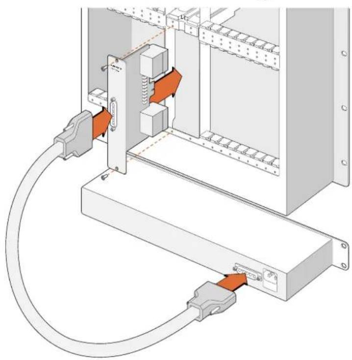
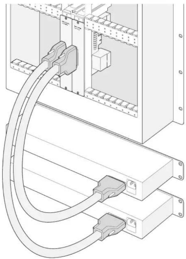
The Universal Videohub Power Supply package consists of a power card, a power cable and a 1 RU chassis containing the power supply. A second Universal Videohub Power Supply can be installed under the first power supply for failover redundancy. You will need to provide a standard IEC cord with a C13 connector for each power supply.
1 Ensure that any new power supplies are disconnected from any electrical source. Orient the power card so that the MAIN POWER label appears at the top of the card.
2 Insert the power card into either of the two power card slots.
3 Use a number 02 size Pozidriv screwdriver to secure the power card with its two screws. If you have a second power card, install it now into the spare power card slot.
4 Connect the power cable from the power card to the power supply. Tighten the thumb screws on both power connectors. Repeat this step if you have a second power card and second power supply. It does not matter which power card connects to which power supply.
5 Connect an IEC cord from each power supply to a mains wall socket and turn on the power.
Congratulations! Your Universal Videohub 288 is now ready to start routing video!
natural_image
Technical diagram of an electrical panel assembly with a highlighted component (no text or symbols present)Installing a Universal Videohub SDI Interface Card.
natural_image
Diagram of an electrical connector assembly with orange arrows indicating connection points (no text or symbols present)The Universal Videohub Power Supply consists of a power card which is inserted into the Universal Videohub 288 and then connected to a 1 RU chassis located under the Universal Videohub 288.
Installing a second Power Supply while Universal Videohub 288 is running
If you wish to install a redundant or replacement power supply while Universal Videohub 288 is already running from a power supply, please carry out the installation procedure in the following order:
1 Ensure that the new power supply is disconnected from any electrical source.
2 Orient the new power card so that the MAIN POWER label appears at the top of the card. Now insert the power card into the spare power card slot.
3 Use a number 02 size Pozidriv screwdriver to secure the power card with its two screws.
4 If you are installing a redundant power supply for the first time, install the 1 RU chassis below the first power supply, leaving 1 RU of clearance between the two power supplies for heat dissipation. If you are installing a replacement power supply, install the replacement 1 RU chassis where the faulty unit was previously located.
5 Connect the new power cable between the connectors on the new power card and the new power supply. Tighten the thumb screws on both power connectors.
6 Connect an IEC cord from the new power supply to the wall socket and turn on the power.
Removing a Power Supply while Universal Videohub 288 is running
If you need to remove a faulty power supply while Universal Videohub 288 is running from another power supply, please carry out the removal procedure in the following order:
1 Switch off the power to the faulty power supply and unplug its IEC cord.
2 Disconnect the power cable between the power card and the faulty power supply.
3 Remove the faulty 1 RU chassis and associated power card. Ensure all components from the faulty unit are placed somewhere where they will not be confused with a new replacement unit.
natural_image
Technical line drawing of a cable connector assembly inside an electrical enclosure (no text or symbols)Two Universal Videohub Power Supplies can be Installed for power redundancy with the Universal Videohub 288.
Universal Videohub 72
natural_image
Front view of a rack-mounted industrial control unit with multiple ports and connectors (no visible text or labels)What you need to get started
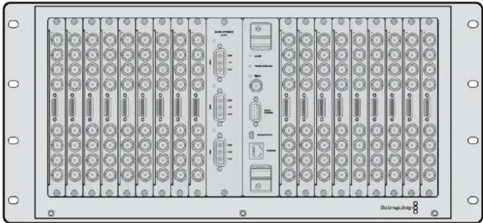
Universal Videohub 72 is a medium-sized modular router ideal for growing facilities. It features an 18 card rack frame that can be filled with any combination of BNC SDI or optical fiber SDI interface cards. When fully populated with a crosspoint card, a power card, 18 SDI interface cards and 18 deck control cables, Universal Videohub 72 provides 72 SDI inputs, 72 SDI outputs, 72 bidirectional RS-422 deck control ports, reference input, redundant power supply options and powerful Videohub routing control software for Mac and Windows.
Occasionally, the internal software of the Universal Videohub 72 will need to be updated. Videohub Setup will prompt you if an update is required. The utility uses the USB 2.0 connection and you will need to provide a USB 2.0 type A to mini B male cable.
Universal Videohub 72 ships as an empty rack frame, except for a removable fan tray and fans. All other hardware components, including SDI interface cards, deck control cables, crosspoint card and power supplies must be purchased and installed separately. SDI interface cards can be purchased as your facility grows and don't need to be installed all at once. This section is designed to help you decide which components you will need before you build your Universal Videohub 72.
See the 'SDI Interface Card' and 'Universal Videohub Interface Cards' sections for more information on the different interface cards available for your Universal Videohub.
Universal Videohub 72 Crosspoint Card
This module contains the crosspoint processor for switching video routes and changing deck control ports. Ethernet, USB and serial ports are located on the card for router control.
A Reference input is located on the card for connection to a tri-level sync or black burst genlock signal.
An Alarm light will illuminate on the card if user intervention is required, e.g., if inadequate cooling has caused Videohub to overheat. Alarm notification is supplied by the GPI (General Purpose Interface) output to other devices.
A Power Overload light will illuminate on the card if inadequate power is being supplied to the unit for the number of cards installed.
Router Control Cable
Remote router control is performed via 10/100Base-T Ethernet or serial. If router control is performed via Ethernet, the integrated Videohub Server is used. This means you only need to provide an Ethernet cable to connect Universal Videohub 72 to your Ethernet network switch.
Third party router controllers can control Universal Videohub 72 via Ethernet, or as an RS-422 slave device, for router crosspoint switching. Please refer to the Developer Information section of this manual for Videohub and RS-422 protocols.
natural_image
Technical line drawing of a computer chassis with ports and connectors (no text or symbols)Universal Videohub Power Supply Includes a power card, 1 RU chassis and connecting power cable.
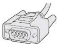
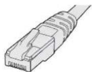
Serial Cable Standard RJ45
Ethernet Cable
Power Supply
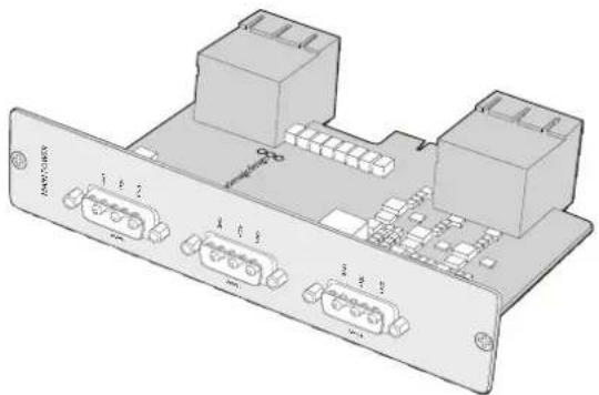
The Universal Videohub 450W Power Card provides connections for up to three 150W brick-style power supplies, which must be purchased separately.
When fully populated and running at maximum power consumption, Universal Videohub 72 can be powered by two 150W brick power supplies. A third power supply can be connected to ensure continued operation should one power supply fail. The 150W power supplies are universal power supplies for use in all countries. You will need to provide a standard IEC cord with a C13 connector for each power supply. When fully populated with three power supplies, three mains power sockets will be required.
Building Universal Videohub 72
9 rack units of space should be reserved for the installation of Universal Videohub 72 including access space for the drop-down fan tray as well as free space for heat dissipation. Only 7 RU is required if Universal Videohub 72 is mounted at the top of an open rack. Universal Videohub 72 is 5 rack units high and 6 inches thick. You can rack-mount Universal Videohub 72 facing forwards or reversed, or even mount it in the rear of the rack to leave space for other equipment. 2 RU of space should be left above Universal Videohub 72 for heat dissipation unless mounted at the top of an open rack where there is no obstruction to airflow above.
Universal Videohub 72 contains electrostatic sensitive devices. It is essential to discharge yourself of static electricity before handling any of these devices, just as you would when installing devices into a computer. We recommend the use of an antistatic wrist strap when handling any of these devices.
Installing a Universal Videohub 72 Crosspoint Card
Now that your Universal Videohub 72 has been mounted in a rack, it needs to be fitted with a crosspoint card. The crosspoint card is the brains of any Universal Videohub and performs video route and deck control switching. Universal Videohub 72 Crosspoint cards are hot-swappable, meaning they are designed to be installed and removed while the Universal Videohub is running.
natural_image
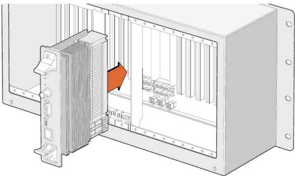
Diagram of an internal server rack with a highlighted orange arrow indicating a component (no text or symbols present)Installing a Universal Videohub 72 Crosspoint Card.
1 Hold the crosspoint card in a vertical orientation by its two levers. The Ethernet port should be towards the bottom end of the card.
2 Gently insert the card into its slot, ensuring the top and bottom edges follow the black guides.
3 Firmly push both levers flat to fully engage the multi-pin connectors with the motherboard. Mating pins ensure that the card precisely engages with the motherboard without damaging the multi-pin connectors.
4 Use a number 01 size Pozidriv screwdriver to secure the two levers on the crosspoint card.
natural_image
Technical diagram of an electrical panel assembly with a highlighted component (no text or symbols present)Installing a Universal Videohub SDI Interface.
Universal Videohub 72 Crosspoint
Universal Videohub Status LEDs
The status LEDs marked 'alarm', 'power overload' and 'ref in' provide you with an indication of the current state of the Blackmagic Universal Videohub 72 Crosspoint. The following LED conditions provide specific information about the status of the unit.
| Red ‘alarm’ LED | ||
| Off No error. Normal operation | ||
| On Error condition. Other error. Telnet into device to get error code. | ||
| 1 flash Error condition. Fan failure. | ||
| 3 flashes Error condition. No redundant power supply. | ||
| Red ‘power overload’ LED | ||
| Off | Normal operation. Inactive / Slave mode. This should only be seen on a Blackmagic Universal Videohub 288 with 2 crosspoints | |
| Slowly blinking Normal operation. Active / Master mode. | ||
| On Error condition. Power overload. Not enough power is being supplied | ||
| White ‘ref in’ LED | ||
| ● | Off Normal operation. | No reference connected. |
| ○ | On Normal operation. | Reference connected. |
TIP Blackmagic Universal Videohub 72 Crosspoint has amber colored LEDs mounted inside the device that should only be visible when the heatsink is removed for development purposes. However, in some cases a dim amber light may be visible through the hole that has been drilled for the 'alarm' LED. This is not an error condition.
A healthy Universal Videohub 72 Crosspoint should display the following:
| Red ‘alarm’ LED Off | ||
| Red ‘power overload’ LED Slowly blinking or off. | ||
| White ‘ref in’ LED Solid white or off | ||
Installing Interface cards
Installing a Universal Videohub SDI Interface or Universal Videohub Optical Interface is easy and the steps are the same for installing each type of interface card.
1 Hold the card in a vertical orientation with the identification LED at the top of the card. The identification LED looks like a pin hole near the top left of the top connector.
2 Gently but firmly insert the card so that it follows its guides and plugs into the PCI slot in the motherboard. Use a number 02 size Pozidriv screwdriver to secure the interface card to the Universal Videohub frame.
See the 'SDI Interface Card' and 'Universal Videohub Interface Cards' sections for more information on the different interface cards available for your Universal Videohub.
Installing a Universal Videohub 450W Power Card
The Universal Videohub 450W Power Card features three power connectors, which can be connected to 150W power supply bricks for up to 450W of power. This power card is suitable for powering a fully populated Universal Videohub 72 with two power supplies connected.
A third connected power supply provides failover redundancy should one power supply fail.
1 Ensure that the power supply is disconnected from any electrical source.
2 Orient the power card so that the MAIN POWER label appears at the top of the card.
3 Insert the power card into its slot on the motherboard. Use a number 02 size Pozidriv screwdriver to secure the power card with its two screws.
4 Connect three Universal Videohub 150W Power Supplies.
If you need to remove or replace the power card, power off and disconnect all connected power supplies before removing the power card.
If you have only partially populated your Universal Videohub 72 with interface cards, you might be able to power it with a single 150W power supply and preferably use a second power supply for failover redundancy. If you choose this option:
1 Temporarily disconnect the second power supply and then check the Power Overload light on the crosspoint card after installing any cards.
2 If the Power Overload light illuminates, you will have to add a 150W brick power supply or remove some cards to ensure that all cards are receiving power.
3 Reconnect the second power supply when you have finished checking the Power Overload light.
natural_image
3D diagram of a network device rear panel with multiple ports and connectors (no text or labels visible)Universal Videohub 450W Power Card can be connected to three 150W power bricks.
For peace of mind, we recommend connecting and powering the three power supplies at all times to ensure sufficient power, and power redundancy, with all card combinations.
If you need to remove or replace a 150W Power Supply while Universal Videohub 72 is still running, power off the brick while being careful to avoid switching off power to the remaining power supplies. Unplug the IEC cord and then unscrew and disconnect the power supply from the Universal Videohub 450W Power Card.
Congratulations! Your Universal Videohub 72 is now ready to start routing video!
SDI Interface Card
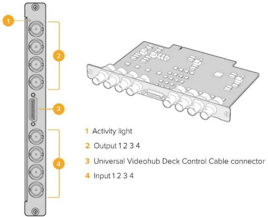
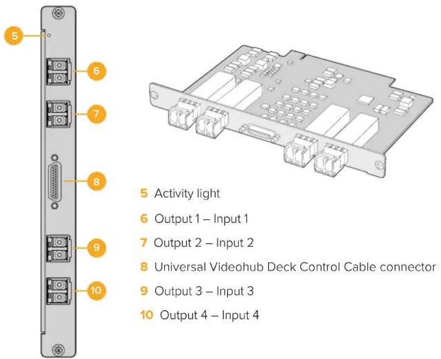
SDI interface cards feature 4 SDI inputs, 4 SDI outputs and a connector for a Universal Videohub Deck Control Cable. All SDI connections support auto detection of SD, HD or 3G-SDI, and reclocking on all SDI outputs. Simultaneous routing of 2K, HD, SD video and DVB-ASI are supported with Universal Videohub. SDI interface cards are designed to be installed while Videohub is running and become active immediately. They do not require Videohub to be power cycled. You will need a number 01 and a number 02 size Pozidriv screwdriver to install the various cards.
There are two models of SDI interface cards that can be used with Universal Videohub:
■ Universal Videohub SDI Interface card with BNC connectors.
- Universal Videohub Optical Interface card has standard SFP transceiver modules with 1310 nm laser drivers and receivers. Each module includes an LC connector port to be used with single-mode optical fiber cables.
Universal Videohub Interface Cards
Universal Videohub SDI Interface card
Universal Videohub Optical Interface card
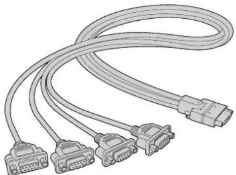
Universal Videohub Deck Control Cable
This cable features a single serial port at one end, for connection to both types of SDI interface cards, and four RS-422 deck control ports at the other end.
natural_image
Illustration of multiple connected VGA connectors (no text or symbols)Universal Videohub Deck Control Cable
3G-SDI Videohub Routers
Blackmagic 3G-SDI Videohub Routers
3G integrated Videohub models support up to 3G-SDI and are designed to suit facilities and workgroups of varying sizes.
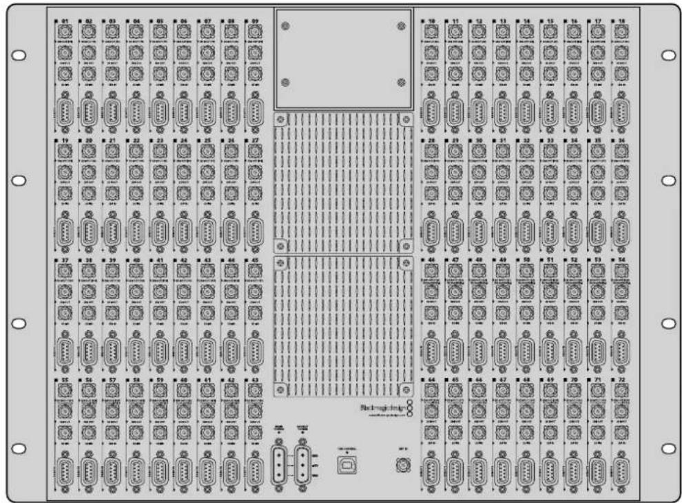
Broadcast Videohub has 72 SDI inputs, 144 SDI outputs, 72 bidirectional RS-422 deck control ports, reference input, redundant power supplies and is 8 rack units high.
Studio Videohub has 16 SDI inputs, 32 SDI outputs, 16 bidirectional RS-422 deck control ports, reference input, a universal power supply and is 2 rack units high.
Compact Videohub has 40 SDI inputs, 40 SDI outputs, reference input, redundant power supply connections and is 2 rack units high.
Micro Videohub has 16 SDI inputs, 16 SDI outputs, reference input, a universal power supply and is 1 rack unit high.
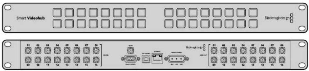
Smart Videohub has 16 SDI inputs, 16 SDI outputs, reference input, a universal power supply, a built in control panel and is 1 rack unit high.
All SDI connections support auto detection of SD, HD or 3G-SDI, and reclocking on all SDI outputs. Simultaneous routing of 2K, HD, SD video and DVB-ASI is supported.
The Broadcast and Studio Videohubs must be connected via USB 2.0 to a host computer running the Videohub server software, which can then be shared over an IP network in much the same way as USB printer sharing. The Micro and Compact Videohubs connect directly to the network, but still receive software updates via USB. Prior to connecting any devices to your Videohub, you must nominate a computer to be the Videohub "Server" and to perform Videohub sharing via USB. You can use almost any computer for the Videohub Server, such as an editing workstation. However the Videohub Server computer must remain powered at all times so that Videohub settings can be modified. You will need to provide a standard USB 2.0 type A-B male cable to connect Broadcast Videohub to the server computer.
The same USB cable can be used for applying internal software updates. Blackmagic Videohub Setup will prompt you if an update is required. The utility runs on the Videohub Server computer and uses the USB 2.0 connection to update your Videohub.
Third party router controllers can control your Videohub via Ethernet for router crosspoint switching. The Videohub Ethernet protocol is documented in the Developer Information section of this manual.
Videohub models with redundant power supplies require one power supply to operate but includes two so continued operation is ensured if one happens to fail. Included power supplies are universal for use in all countries. You will need to provide a standard IEC cord with a C13 connector for each power supply.
natural_image
Front view of a network equipment rack with multiple ports and connectors (no visible text or labels)Blackmagic Broadcast Videohub

Blackmagic Studio Videohub

Blackmagic Compact Videohub
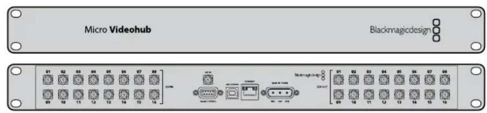
Blackmagic Micro Videohub
Blackmagic Smart Videohub
Using the Smart Videohub Control Panel
Smart Videohub features a built in 32 pushbutton control panel on the front of the router. Routing changes can be made without needing a computer as there is a pushbutton for each SDI input and output on Smart Videohub. Remote router control can also be used with Smart Videohub.
The pushbuttons on the left of the control panel correspond with the 16 SDI inputs and the pushbuttons on the right correspond with the 16 SDI outputs.
When power is connected to Smart Videohub, the top-left destination button will illuminate white along with its corresponding source button.
To change routes:
1 Select a destination button and its corresponding source button will illuminate.
2 Press the desired video source button to connect a new source to the destination. The original source button's LED will turn off and the new source button will light up. The new video source will immediately be connected and viewable on the destination device, such as an SDI monitor.
3 To change another route, select another destination button and then select a new source button.
The pushbuttons on Smart Videohub directly control the integrated Videohub Server and override any existing routes, including destinations locked with Videohub software.
The illuminated pushbuttons display the last route made with the Smart Videohub control panel. However, if you select the same destination pushbutton as another remote user and they change the source to that destination, you will see the change reflected on your Smart Videohub.

The built in pushbutton control panel allows routing changes to be made without the need for a computer.

Every pushbutton on the front panel of Smart Videohub has a matching SDI input or output on the rear panel.
Videohub Router Monitoring
Router Monitoring with Blackmagic MultiView 16
MultiView 16 is a single rack SDI multi viewer for simultaneously displaying up to 16 different SDI signals in a variety of formats on a single monitor. With Ultra HD support and remote control using the intuitive Videohub software, you get the ultimate monitoring solution for your Blackmagic Videohub routers!
Each of the Blackmagic MultiView 16's SDI inputs has its own loop output so you can feed each signal to other SDI equipment. Two 6G-SDI outputs and two down converted HD-SDI outputs let you connect HD or Ultra HD monitors. The HDMI output switches between HD and Ultra HD based on the format that your connected monitor supports. All SDI connections support auto detection of SD, HD, 3G-SDI and 6G-SDI, reclocking on all SDI outputs, and a reference input for connecting to switchers and other broadcast video equipment.


natural_image
Front view of a rack-mounted network device with multiple ports and connectors (no visible text or labels)You can operate Blackmagic MultiView 16 using the built in control panel, or remotely via Ethernet or serial connections if mounted in a rack where you don't have access to the front panel. Third party router controllers can control the unit via Ethernet, or as an RS-422 slave device for router switching.
The multi view output can be switched between different layouts, such as 1x1, 2x2, 3x3, or you can see all your inputs together using 4x4 view. Blackmagic MultiView 16 can even be used to distribute four independent native HD signals in one Ultra HD picture!
Blackmagic MultiView 16 is AC powered.
Using the Built in Control Panel and LCD
Blackmagic MultiView 16's control panel provides fast access to settings, sources and views.
LCD and Home Screen
The built in LCD provides a fast and intuitive way to view and adjust your settings. The 'home' screen is the default screen when first powering your Blackmagic MultiView 16 and displays a convenient overview of settings, which includes the following information:
HD video output format
This information is located in the upper left corner and displays the 1080i59.94 or 1080i50 HD format setting via the HD-SDI outputs.
Audio input
This information is located next to the HD-SDI video output format and displays which SDI input is being used to embed audio into the HDMI and SDI multi view output signals.
Multiview layout
This displays the arrangement of your views. You can optimize the display depending on the number of inputs connected.
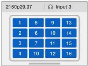
The home screen is the default display on the control panel LCD. If you have adjusted a setting, you can always return to the home screen by pressing the 'menu' button.
Menu Buttons Explained

SRC and VIEW
Use the 'src' and 'view' buttons to open the 'source' and 'view' settings. These buttons let you select which input source you want to display on a desired view.
1 Press the 'view' button to open the view screen. The view section on the lower half of the LCD will be active.
2 Press a numbered button on the control panel to select your desired view, or alternatively you can use the rotary knob to scroll through the views. Confirm your setting by pressing the 'set' button.
3 Press the src button. The source section on the upper half of the LCD will become active.
4 Press a numbered button on the control panel to select your desired input, or alternatively you can use the rotary knob to scroll through your inputs on the LCD. If you have customized your input labels, they will be displayed accordingly in the upper half of the LCD.
5 Press the 'set' button to confirm the setting.

SOLO
You can monitor a view in fullscreen mode by pressing the 'solo' button. With solo enabled, press the number buttons on the control panel to select which view to monitor, or you can use the rotary knob to scroll through your views. Press 'solo' again to return to the multi view layout.

SET
Press the 'set' button to select and confirm settings. When you press the set button to select a menu item, the adjustable setting field will become underlined and both the 'set' and 'menu' buttons will flash. After changing a setting, press the set button again to confirm the change.

MENU
Press the 'menu' button to open the settings screen. After adjusting a setting, you can also press the 'menu' button to return to the home screen.

NUMBERS
The number buttons are used to select your inputs and views for the source and view settings.
The buttons can also be used to select which SDI input you want to use for the 'audio in' setting.


SRC, VIEW and SET
Press the SRC and VIEW buttons on the control panel to open the source and view settings. To adjust settings, use the number buttons or the rotary knob, then press 'set' to confirm.

The source and view settings screen highlights which setting you are currently adjusting. Any customized input labels will be displayed accordingly.


SOLO and MENU
Press the 'solo' button to enter fullscreen mode. Press the 'menu' button to enter the settings page and to return to the home screen.


Blackmagic Videohub Software
To install your Blackmagic Videohub software
Videohub software runs on the latest 'Mojave' version of macOS. It also runs on the 32 and 64 bit versions of Windows 10.
Windows installation
1 Double click the installer file from the supplied media or from your downloads folder if you downloaded the software from the Blackmagic Design website.
2 Follow the install prompts and accept the terms in the License Agreement and Windows will automatically install the software.
Click the Windows Start button and then All Programs>Blackmagic Design>Videohub. The following three applications are contained within the folder: Videohub Control, Videohub Setup and Videohub Hardware Panel Setup.
Mac OS installation
1 Double click the installer file from the supplied media or from your downloads folder if you downloaded the software from the Blackmagic Design website.
2 Follow the install prompts to complete the installation.
A folder called "Blackmagic Videohub" will be created within your Applications folder containing the following three applications: Videohub Control, Videohub Setup and Videohub Hardware Panel Setup.
Refer to the software sections in this manual for more information.
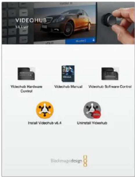
To install the Videohub software, double click the installer and follow the prompts.
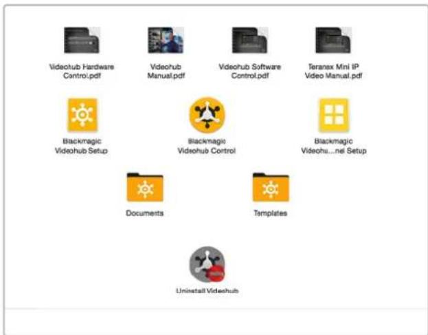
The Blackmagic Videohub folder contains three Videohub applications. Videohub Control, Videohub Setup, and Videohub Hardware Panel Setup.
Blackmagic Videohub Setup
Blackmagic Videohub Setup is an administration utility used to configure your Videohub, customize your input and output labels, name your Videohub, and adjust the network settings, and more.
NOTE After installing the Blackmagic Videohub software, the Videohub Server is also automatically installed.
Network Settings
If your Videohub connects to a network via Ethernet, you can use Blackmagic Videohub Setup to set the IP address.
Connect the Videohub to your computer via USB and follow these steps:
1 Launch Blackmagic Videohub Setup and it will automatically display any Videohubs that are connected to your network.
2 If you have multiple Videohubs you can use the left and right arrows to cycle through the devices.
3 Select your Videohub by clicking on either the picture or the configuration icon.
4 Click on the Configure tab and entre the IP address and also the Subnet Mask and Gateway addresses if required.
5 Click the 'save' button to close the window and apply your changes. Click 'cancel' to discard any changes.
TIP If your Videohub has a front panel LCD, you can use the front control panel to select your IP address. See Configuring Network Settings with a Built In Control Panel earlier in this manual for more information.
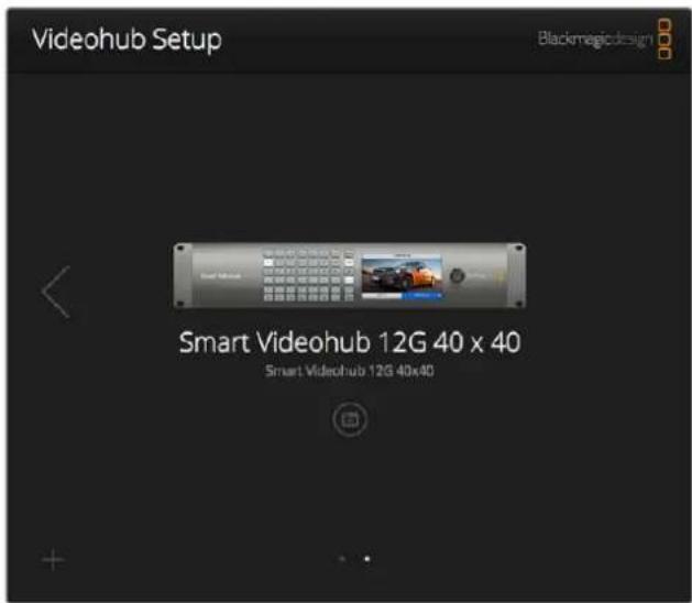
Blackmagic Videohub Setup
Customizing Labels
Blackmagic Videohub Setup is also used to enter labels. Note that port labels on an IP Videohub cannot be edited through this utility, as these labels come from the connected IP Video devices. The labels are stored on the connected Videohub and are also visible on the other control panels connected to your network.
Customize Input Labels
1 Click on the 'inputs' tab and then click on the first input that you wish to label.
2 Enter label names for your inputs and click the 'save' button to close the window.
For larger Videohubs, use the 'jump to' dropdown menu to quickly jump to a different range of inputs.
Customize Output Labels
1 Click on the 'outputs' tab and then click on the first output that you wish to label.
2 Enter label names for your outputs and click the 'save' button to close the window.
Customize Remote Labels and Port Directions
1 Click on the 'remotes' tab and then click on the first remote that you wish to label.
2 Enter the label name and then click on the Port Direction icon and select from Auto, In or Out.
3 When you have finished labeling all your remotes click the 'save' button to close the window.
Automatic port direction simplifies configuration and works well with most editing systems. However, if you need to make instant port direction changes, you can set the port direction manually. Non-Roman character sets can also be used with the Smart Videohub family.
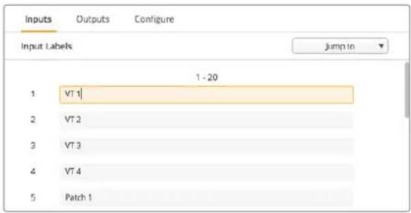
Customize Input Labels
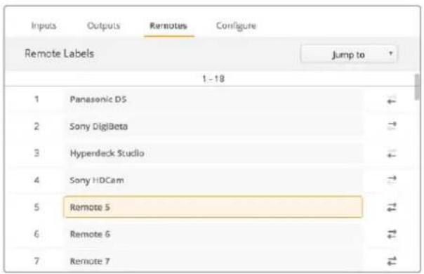
Customize Remote Labels and Port Directions
Saving and Loading Labels
To save your labels, click on Settings (the gear icon) and select 'save label set'. Choose a location to store the file and click save.
To load your labels, click on Settings and select 'load label set'. Navigate to your previously saved label set file and click load.
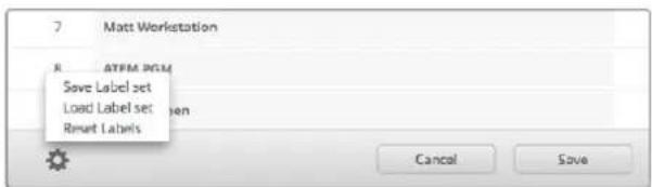
Saving and Loading Labels
Naming your Videohub
Give your Videohub a unique name to make it easy to identify when controlling it over a network.
1 Click on the 'configure' tab and then click in the 'name' text field.
2 Enter your Videohub's name and use things such as location or owner to make it easy for users to recognize and then click the 'save' button to close the window.
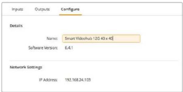
Name your Videohub so it's easy for network users to identify.
Updating your Videohub's Internal Software
Occasionally, the internal software in your Videohub will need to be updated. Updates to internal software can provide new features, compatibility with new hardware and support for new formats.
Please follow these steps to update your Videohub's internal software:
1 Connect your computer to the Videohub's USB 2.0 connector.
2 Launch Blackmagic Videohub Setup and it will automatically display any Videohubs that are connected to your network.
3 Select your Videohub by clicking on either the picture or the configuration icon.
4 The utility will inform you if an update is required.
5 If an update is required, click the Update button and allow the software to install. Make sure not to unplug the Videohub while the update is in progress.
6 Click the Close button when the update is finished.
Do not unplug the Videohub while the update is in progress.
Blackmagic Videohub Control
Using Blackmagic Videohub Control provides a fast and intuitive way to view and switch between multiple sources and destinations. Videohub Control is easy to use because it operates on a single video output at a time. Selecting a destination (output) pushbutton shows which source (input) is connected to it by illuminating the source pushbutton. To change the source, simply click on a different source pushbutton. It's that easy!
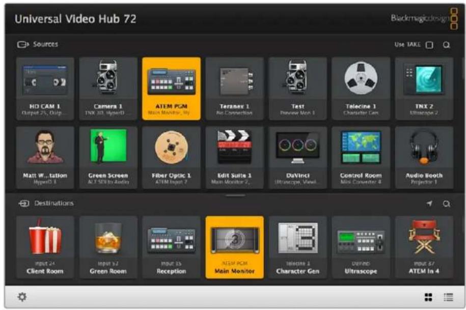
Videohub Control provides an intuitive, icon-driven representation of the Videohub connections.
Selecting a Videohub
Launch Videohub Control and click on Settings (the gear icon) and choose 'select Videohub'. Click on the Videohub that you wish to control. If you have customized your labels, the names you assigned will appear within the software. All Videohubs on the network, including IP Videohubs, will appear in this list. Refer to the 'customizing labels' section for more information.
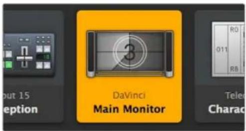
This destination is unlocked and is available to any Videohub user on the network. The associated video source is illuminated in the Sources panel and the source name "DaVinci" is displayed.
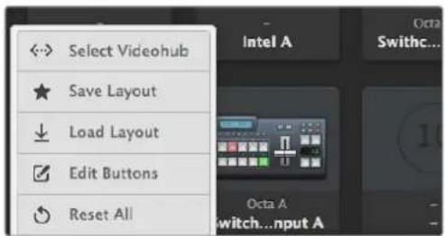
Click on the 'Select Videohub' button and then select the Videohub you wish to control.
Adding Pushbuttons
Select the Settings button and then select 'edit buttons'. Click on the Add button and choose whether to add a source or destination pushbutton. The Set Button window appears and allows you to set the SDI source or destination, RS-422 deck control and icon for the pushbutton. In most cases, deck control is grouped with the associated SDI connections.
Viewing Routes
In order to see which video source has been routed to a video destination, such as a monitor, press the button in the destinations panel to make the button illuminate. The associated video source button will illuminate in the sources panel, making it immediately obvious which source is connected to the monitor.
Switching Routes
In order to change the video source from a tape deck to a video camera, press a camera pushbutton in the sources panel to immediately illuminate the camera pushbutton and route video to the video monitor. The tape deck button is no longer illuminated and is disconnected from the video monitor.
Refer to the ‘controlling videohub with software’ section for more information on using Videohub Control.
| Resizing the Interface | Click and drag the bottom right hand corner to proportionally resize the interface to best fit your screen size. Alternatively, drag a window edge to resize either vertically or horizontally. |
| Resizing the Sources and Destinations Areas | Drag the divider bar up and down and use the scroll bars to scroll the respective areas. |
| Switching Views You can switch between pushbutton view and list view by clicking the icons in the bottom right corner. | |
| Using the Dynamic Search Both the sources and destinations areas contain a search icon, which allows you to search for text dynamically. This is useful if you have many pushbuttons and quickly want to locate a pushbutton with a specific name. Begin by typing the name you wish to search for. As you type each letter, the pushbuttons that are displayed will be dynamically filtered. | |
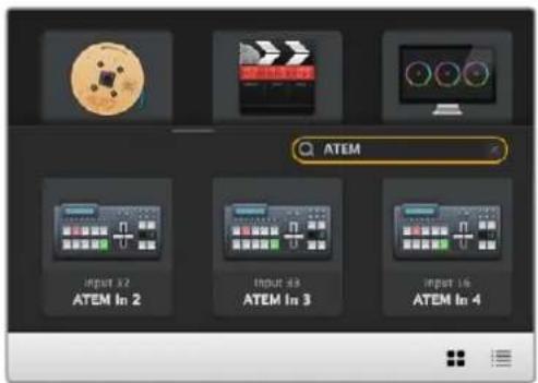
The word 'ATEM' is entered into the Destinations Search Box and the filtered results are displayed.
Blackmagic Videohub Control at a Glance
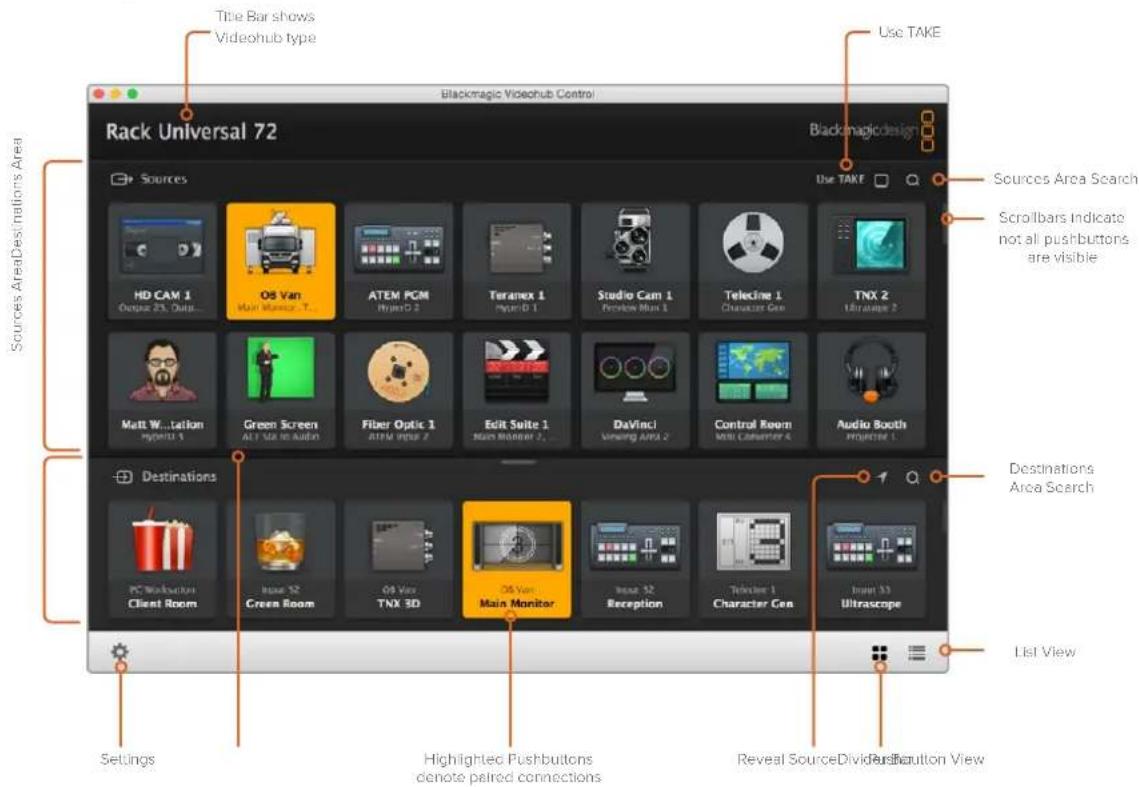
Click and drag the window edges to resize Blackmagic Videohub Control to fit your screen size. Drag the Divider Bar up or down to reveal more or less of the "Sources" and "Destinations" areas and use the Scroll Bars to scroll the areas.
Settings Menu
| Select Videohub | Select from a list of Videohubs that are currently connected to your network. | |
| Save Layout | Save customized pushbutton layouts for the different environments in which you use your Videohub. | |
| Load Layout | Load previously saved pushbutton layouts. | |
| Edit Buttons | Displays the Edit Buttons for editing the pushbuttons. | |
| Reset All | Displays all of the inputs and outputs of the connected Videohub and replaces customized icons with the default icon. Source,destination and deck control settings are maintained. |
Edit Buttons
| Add Add a source or destination pushbutton. | ||
| Edit | Allows you to set the SDI source or destination, deck control and the icon for the selected pushbutton. | |
| Lock and Unlock | Lock a destination to avoid accidentally changing the video source which is routed to that destination. If you click on a pushbutton that's locked, the Lock button changes into an Unlock button. Simply click the Unlock button to unlock the destination pushbutton. | |
| Clear | Deletes source, destination and deck control settings as well as the icon for the selected pushbutton. | |
| Remove Removes the selected pushbutton. | ||
| Done | Done | Click the Done button to exit the edit mode. |
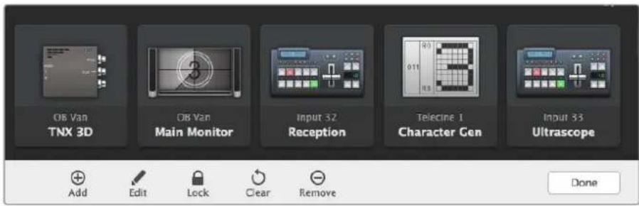
Click Edit Buttons to display the above buttons.
Using Pushbuttons
| Adding Pushbuttons | Select the Settings button and then select “Edit Buttons”. Click on the Add button and choose whether to add a source or destination pushbutton. The Set Button window appears and allows you to set the SDI source or destination, RS-422 deck control and the icon for the pushbutton. In most cases, deck control is grouped with the associated SDI connections, e.g., SDI Input 1 would be associated with the corresponding Remote 1. |
| Editing Pushbuttons | Select “Edit Buttons” and click the pushbutton you wish to edit. Click on the Edit button and modify the source or destination, deck control settings and the icon as required. |
| Set Button | The Set Button window allows icon selection, source or destination selection and deck control configuration. |
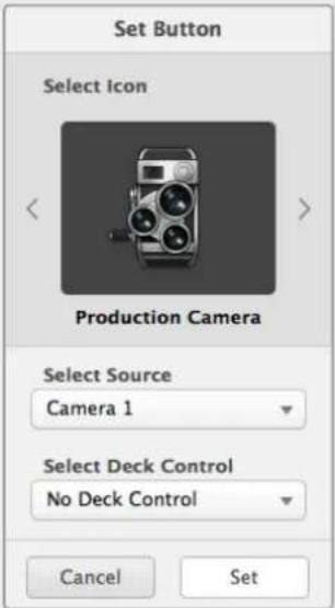 | |
| Moving Pushbuttons | Select the Settings button and then select “Edit Buttons”. Click and drag the pushbutton to a new position. |
Viewing and Switching Routes
| Viewing Routes | In order to see which video source has been routed to a video destination, such as a monitor, press the button in the destinations panel to make the button illuminate. The associated video source button will illuminate in the sources panel, making it immediately obvious which source is connected to the monitor. |
| Reveal Source | If you select a destination but the source is currently positioned offscreen, clicking the Reveal Source button will scroll the Sources area to display the source pushbutton. |
| Switching Routes Select the destination icon followed by the source icon. | |
Use TAKE Confirmation before Switching Routes
You may wish to enable the "Use TAKE" button to help prevent unintentional changes to video routes. Once enabled, any attempt to change a video route using a pushbutton will cause a red "TAKE" button to appear. Select the button to confirm or click the current source or destination pushbutton to cancel.
This destination is unlocked and is available to any Videohub user on the network. The associated video source is illuminated in the Sources panel and the source name "DaVinci" is displayed.
Locking and Unlocking Routes
Locking a destination will avoid accidentally changing the video source which is routed to that destination. To lock a route, select the destination pushbutton and double click. A padlock icon will appear in the top-right corner of the destination pushbutton and will prevent anyone else from using the destination device until it is unlocked from your computer. Locking a destination still leaves the associated video source available for routing to multiple destinations simultaneously.
Double click the pushbutton to unlock the destination.
You can also lock one or multiple destinations via the edit buttons page. Shift click the destination pushbuttons you wish to lock and click the lock button. If you select a mixture of locked and unlocked pushbuttons, you will have the option to lock the unlocked pushbuttons.
Locking a route between an input and an output also locks the RS-422 deck control connection between the two devices to avoid other users accidentally seizing the deck control belonging to the video source. The RS-422 connection between the video source and video destination will remain locked until the destination pushbutton is unlocked.
TIP To toggle the lock status of a destination, simply double click the destination pushbutton.
A black padlock icon with a curved line above will appear on any destination pushbuttons locked by other Videohub devices. The video destination devices will not be available to you until the destination pushbuttons have been unlocked from the other users' computers and iPads.
If you need to unlock a route set by another user, launch Videohub Setup, select the Outputs tab and click the destination's lock icon.
NOTE It is important to note which routing level is selected, as it will affect the locking of routes. Universal Videohub consists of an SDI video level and an RS-422 deck control level. These levels can be switched together or can be separated for individual switching.
If you have selected SDI 422 on the level controls, it will lock both ports, however, if you select SDI or RS422 it will only lock the selected port. When the RS-422 port is locked you can still switch to SDI video, and when the SDI port is locked you can still switch to RS-422. This means that you can still route video signals even if the RS-422 port is locked, and still have deck control even if the SDI port is locked.
Locally locked destinations display a white padlock icon.
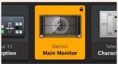
Remotely locked destinations display a black padlock icon.
Serial Control Settings
Third party router controllers can control Videohub with RS-422 serial connections.
If controlling Videohub via RS-422, set the "Leitch protocol" switch to:
- “Leitch Client” if the Videohub is to act as a client of a connected control panel and to listen and respond to the control panel button presses.
- “Leitch Server” if the Videohub is to be controlled from an automation system or third party router control system.
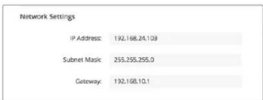
The Videohub Server Configuration options will become active when an Ethernet-equipped Videohub is connected via USB.
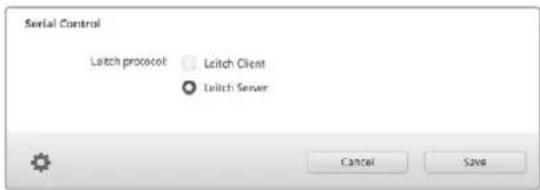
Select either Client or Server when using RS-422 serial control.
Touchscreen Computers
Pushbutton View is designed to be easy to use and look beautiful on a large, touchscreen display. Dedicating a touchscreen computer to the Pushbutton View within the Videohub Control software makes it incredibly easy for users to switch connections between multiple SDI devices without having to see every connected device all of the time.
Using a touchscreen computer provides the fastest way to switch connections which is perfect for a master control room. Both desktop and laptop touchscreen computers can be used.
While touchscreens are perfect for rapidly selecting and routing inputs and outputs, they can be cumbersome for configuring pushbuttons. The width of a human fingertip is much wider than a mouse pointer and is less accurate when tapping on menu options and small icons.
For this reason, we recommend configuring the pushbuttons with a mouse. Once the Videohub pushbuttons have been configured, it will be easy to use a finger to select and route, inputs and outputs, by tapping on Videohub pushbuttons.
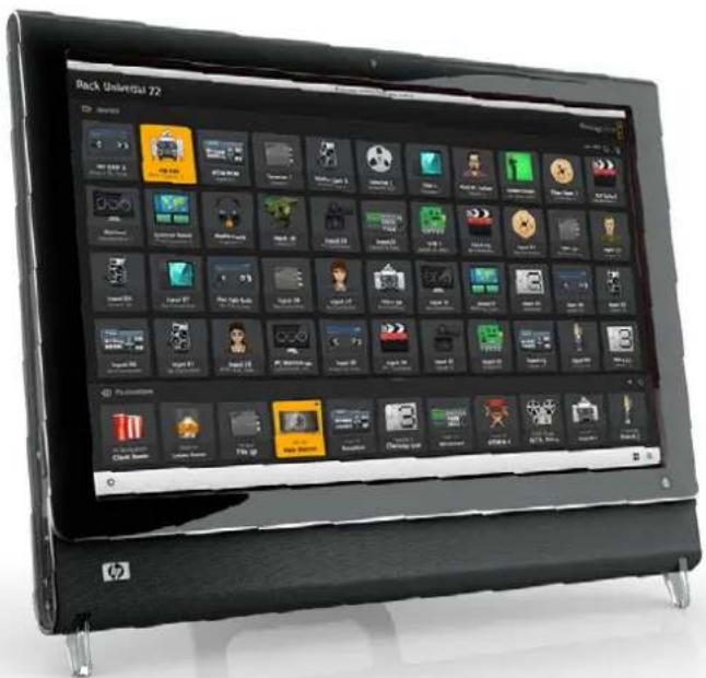
Touchscreens work a little differently to a computer mouse but provide the fastest and easiest way to work with the Videohub Control interface and so are highly recommended. When using a touchscreen computer, you can enable the Use Take option to help avoid unintentional routing changes.
Apple iPad
The Videohub Pushbutton controller interface looks stunning on the high resolution Apple iPad display. Aside from looking great, it also provides the convenience of portable router control anywhere in your facility or even over the Internet via a wireless or cellular connection! If you are already familiar with the Videohub Pushbutton interface on a computer, then there is almost nothing new you need to learn and you'll only notice slight differences between computer mouse control and touchscreen control on the iPad. For information on how to download and install the application, refer to 'installing the Videohub Software on iPad' immediately after this section.
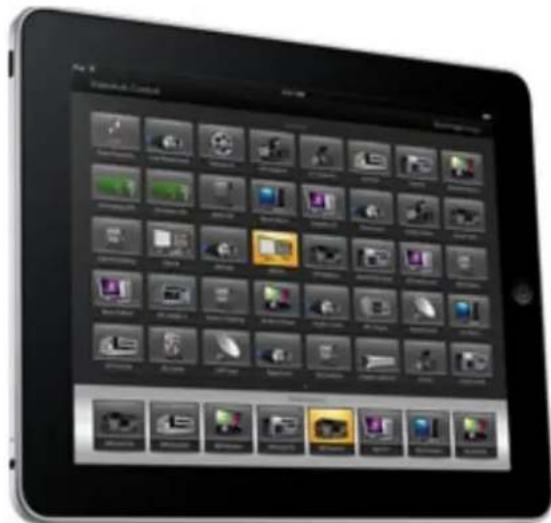
Up to 40 sources and 8 destinations can be displayed in a single Videohub Pushbutton screen on the iPad. Even more sources and destinations can be displayed by flicking the iPad left or right, or tapping to the left or right of the row of dots, to move through multiple Pushbutton screens.
The initial Pushbutton interface
Upon launching the Videohub app on your iPad for the first time, all pushbuttons initially show the generic BNC connector icon, which you can then replace from a selection of icons. If the connections have not yet been labeled, then the source pushbuttons will appear as Input 1 to Input 40 and the destination pushbuttons will appear as Output 1 to Output 8.
If the connections have already been labeled, their names will appear under each of the respective pushbuttons in place of the connector numbers.
Configuring Videohub Pushbuttons on the iPad
Configuring Videohub Pushbuttons on the iPad is easy. Press and hold any Videohub pushbutton to open the Videohub Button Setup window. This window allows you to set the SDI input or output connection, RS-422 deck control and the icon for the pushbutton.
The Clear button will delete all settings for the pushbutton. In most cases, deck control is grouped with the associated SDI connections, meaning an SDI connection named Input 1 would usually be associated with the corresponding Remote 1.
The bottom-right source button is reserved by the Videohub app itself and cannot be configured. This is because if a destination pushbutton is connected to a source that does not appear in the sources panel, the source will automatically appear in the bottom-right pushbutton.
When configuring pushbuttons, only select a deck control connection for those devices that have RS-422 deck control. It makes no sense to assign a deck control connection to a video monitor or camera.
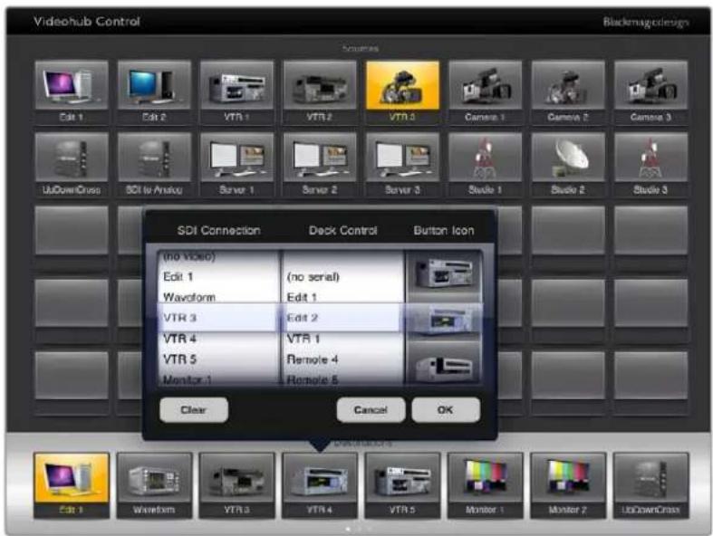
The Videohub Button Setup window allows you to set the SDI input or output connection, RS-422 deck control and the Icon for the pushbutton.
While all icons are available to any pushbutton, it doesn't make sense to choose the icon of a video monitor or transmitter for a source pushbutton unless the source device happens to have a loop-through output.
You may choose to show a particular source or destination pushbutton several times within the one Pushbutton screen or on multiple Pushbutton screens. If a destination pushbutton is routed from a source that appears multiple times in the Sources panel, selecting the destination pushbutton will illuminate all instances of the source pushbutton, regardless of how deck control has been configured for each source pushbutton. Similarly if multiple instances of an output pushbutton appear in the Destinations panel, they will illuminate together when any one has been selected.
Viewing and Changing Routes
In order to see which video source has been routed to a particular destination, such as a monitor, press the monitor's pushbutton in the destinations panel. The monitor button and the associated video source button will simultaneously illuminate, making it immediately obvious which video source is connected to the video monitor, e.g., a HyperDeck Studio Pro.
In order to change the video source from a HyperDeck Studio Pro to a video camera, press a camera pushbutton in the sources panel to immediately illuminate the camera pushbutton and route video to the video monitor. The HyperDeck Studio Pro pushbutton will no longer be illuminated and will be disconnected from the video monitor.
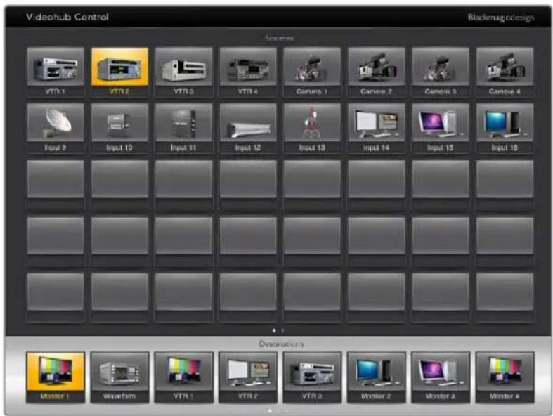
In order to see which video source has been routed to a video destination, tap a destination button and the associated video source button will illuminate.
Locking and Unlocking Routes
Locking a destination avoids accidental changes of the video source being routed to that destination. To lock a route between an input and an output, double-tap the destination pushbutton. A yellow padlock icon will appear in the top-left corner of the destination pushbutton and will prevent anyone else from using the destination device until it is unlocked from your iPad. Double-tap the destination pushbutton again to unlock. Locking a destination still leaves the associated video source available for routing to multiple destinations simultaneously.
Locking a route between an input and an output also locks the RS-422 deck control connection between the two devices. This is to avoid other users accidentally seizing the deck control belonging to the video source.
The RS-422 connection between the video source and video destination will remain locked until the destination pushbutton is unlocked.
A gray padlock icon will appear on any destination pushbuttons that other users have locked. The video destination devices will not be available to you until the destination pushbuttons have been unlocked from the other users' computers and iPads.
If you encounter a gray padlock icon and do not know who locked the video device you can override the lock using the Videohub software on a Mac or Windows computer. When a route is unlocked, the padlock icon will disappear.
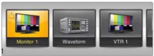
A yellow padlock icon will appear in the top-left corner of the destination pushbutton and will prevent anyone else from using the destination device until it is unlocked from your iPad. A gray padlock icon will appear on any destination pushbuttons that other users have locked.
Installing the Videohub Software on iPad
The Videohub software for iPad can be downloaded using your Apple ID account.
Downloading the Videohub iPad software through your iPad:
1 Tap the 'app store' icon.
2 Tap the 'search' field at the top of the screen and enter 'Videohub'.
3 Tap on the 'get' button next to the 'Blackmagic Videohub app' icon and tap 'install'.
Setting up the IP address in Videohub for iPad:
1 Tap the 'settings' icon.
2 In the 'apps' section, select 'Videohub' and enter your Videohub IP address in the 'Videohub IP address' field.
3 You can now start using your Videohub software by tapping on the Videohub icon on the 'home' screen.
For more information on controlling your Videohub using iPad, see the 'Apple iPad' section in this manual.
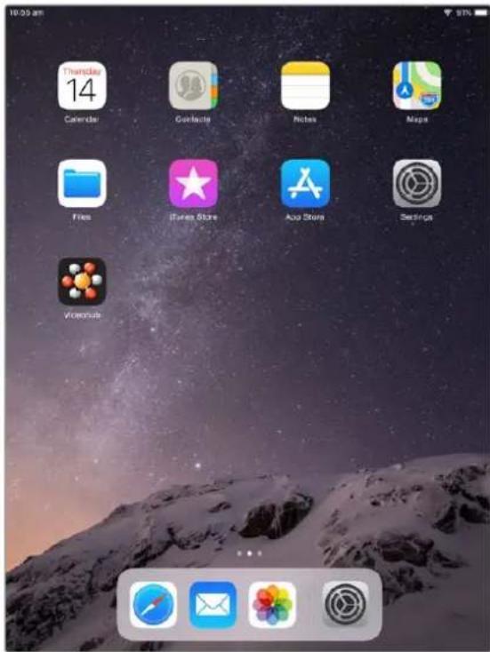
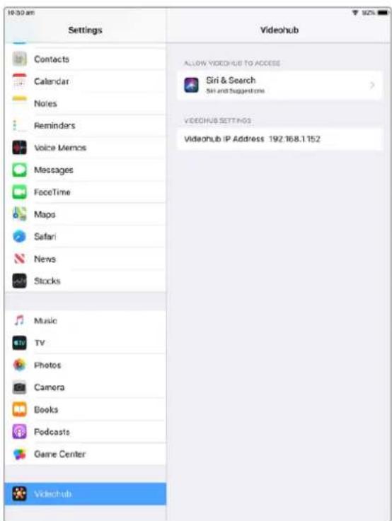
Videohub settings on iPad
Videohub Hardware Panel Setup
When you launch Blackmagic Videohub Hardware Panel Setup, any Videohub control panels discovered on the network will be listed in the Videohub Control Panels pane next to an Ethernet network icon. If several Videohub control panels are listed, but you don't know which one is which, select one of them and then press Identify. This will cause all the buttons of the selected Videohub control panel to flash white.
Select the desired Videohub control panel and you will be able to change its name and control settings. Network settings will remain grayed out and can only be changed via USB.
If the desired Videohub control panel is not found on the network, the unit might not have received an IP address via DHCP. To manually configure the unit with appropriate network settings:
1 Connect the Videohub control panel to your computer via a USB 2.0 cable.
2 Launch Blackmagic Videohub Hardware Panel Setup. If the utility prompts you to update the software, follow the prompts to complete the update.
3 The USB-connected panel will be automatically selected in the Videohub Control Panels pane and will display a USB icon next to its name. You can change all name, network and control settings for the USB-connected unit. When you are finished, the USB cable can be removed.
If your Videohub control panel is selected in the control utility, the pushbuttons on the unit will light up to match what is displayed in the software interface.
Network Settings
Each Videohub control panel requires an IP address to communicate with Videohub via your IP network.
When configuring a Videohub control panel via USB, you can choose DHCP or Static IP. DHCP automatically obtains all the network settings for your Videohub control panel and is the easier choice.
If you decide to use a static IP address, please ask your system administrator for a spare IP address to avoid creating a conflict on your network. You will then need to complete the IP address, subnet mask and gateway details for your Videohub control panel. You must use a static IP address if you are connecting directly to an Ethernet-equipped Videohub, such as Smart Videohub 20x20, without using a network switch.
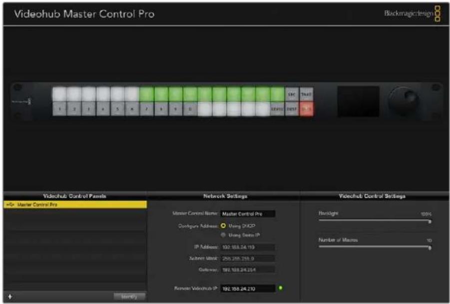
The Blackmagic Videohub Hardware Panel Setup automatically searches your network for any Videohub control panels.
You will also need to complete the IP details for the remote Videohub that you wish to control with your Videohub control panel. The remote Videohub is the Videohub Server. This could refer to a Videohub Server computer or an integrated Videohub Server onboard a Videohub model such as Smart Videohub 20x20.
Any Ethernet or USB connected control units will be listed in the Videohub Control Panels pane with a corresponding icon.
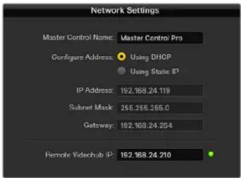
Blackmagic Videohub Hardware Panel Setup network settings.
If you are setting up hardware panel control for an IP Videohub, enter the host computer's IP address in the 'remote Videohub IP' setting field. The Videohub server shares the same IP address with the host computer.
Add Videohub Control
If you already know the IP address of a Videohub control panel but it hasn't automatically appeared in the Videohub Control Panels pane, you can add the unit manually.
1 Press the + (add device) button at the bottom of the Videohub Control Panels pane.
2 Type in the IP address of the Videohub Control Panel and press OK.
3 The Videohub Control Panel will appear in the list with any other devices that are connected to the Videohub.
If the Blackmagic Videohub Hardware Panel Setup does not find a Videohub control panel at the specified address, you can use the Utility to manually add a Videohub control panel when connected via Ethernet or USB.
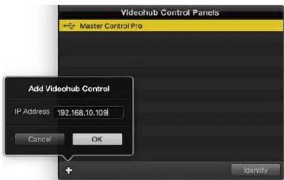
You can manually add a Videohub control panel, by IP address, to the list of Videohub Control Panels.
Load/Save Settings
You can apply settings from an already configured Videohub control panel to other units.
Once you have set up your Videohub Control Panel's settings, choose File>Save Settings. This is useful if you want to set up several units the same way, or keep a back up of your settings.
After loading pre-configured settings on another control panel, you only need to update network settings, including the control panel name.
Configuring Videohub Master Control Pro
Videohub Hardware Panel Setup software lets you customize the hardware features of each Videohub control panel.
Backlight
Adjust the backlight slider as desired to vary the brightness of all backlit buttons.
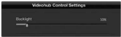
You can adjust the brightness of all backlit buttons in Videohub Master Control.
Creating Button Labels
21 of the buttons can be labeled within the control utility to provide fast selection of common equipment types such as cameras, VTRs and monitors. Any of these 21 buttons can also be configured as macro buttons.
If you haven't done so already, you should standardize the port labels on your Videohub router before labeling any buttons on your Videohub control unit.
Please refer to the 'customizing labels' section for detailed information on customizing your labels.
You are now ready to label the Videohub Master Control Pro buttons.
1 Launch the Videohub Hardware Panel Setup and select your Videohub Master Control Pro from the Panels pane.
2 Click one of the 21 buttons in the picture of the panel. Enter a text label so it partially matches the labels of SDI and deck control ports that you previously entered for your router.
3 Click OK and continue labeling the other buttons as desired.
4 You can immediately test the buttons as you program them and verify the SDI routes are valid.
You can refer to the 'labeling pushbuttons' section for instructions on how to label the physical pushbuttons.
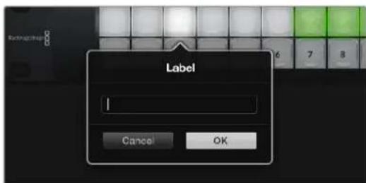
Click on the desired button to edit its label.
Configuring Videohub Smart Control Pro
Videohub Hardware Panel Setup lets you customize the hardware features of each Videohub control panel.
Number of Destinations
Videohub Smart Control can be configured as a Cut-Bus controller or as an XY controller. When configured as a Cut-Bus controller, every button represents an SDI source and there is only one destination.
When configured as an XY controller, Videohub Smart Control Pro can work with up to 24 destinations. The source buttons will illuminate white and the destination buttons will illuminate gold. Use this configuration if you don't intend to dedicate a Videohub Smart Control Pro unit to each destination device.
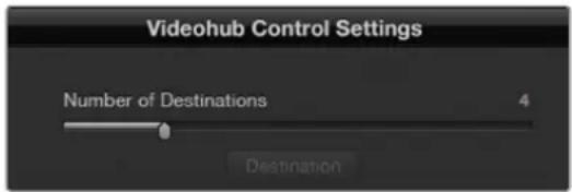
Videohub Smart Control Pro configured with multiple destinations.
Cut-Bus Configuration
1 Drag the Number of Destinations slider to 1.
2 Click on the Destination button. In the Router SDI Out A field, enter the number of the Videohub output port to which the destination device is connected. If your destination device requires dual link SDI, you will need to enter an output port number in the Router SDI Out A & B fields. For quad link SDI, you will need to enter numbers in all four 'out' fields. There is a Router Remote field if your Videohub is also routing RS-422 deck control to the destination device.
3 Click OK to confirm. All the buttons will become white, indicating that they are all sources.
4 Click on each white button in the software interface to configure the source buttons.
5 In the Router SDI In A field, enter the number of the Videohub input port to which the source device is connected. For dual link SDI destinations you will need to enter port numbers for fields A and B, or fields A through D for quad link SDI. There is a Router Remote field if your Videohub is also routing RS-422 deck control from the source device.
6 Click OK to confirm.
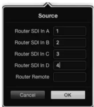
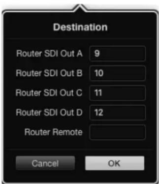
Add a port number for all SDI fields when using quad link SDI destinations
XY Controller Configuration
1 Drag the Number of Destinations slider to the desired number.
2 You can now configure the destination buttons by clicking on each gold button in the software interface. In the Router SDI Out A field, enter the number of the Videohub output port to which the destination device is connected. For dual link SDI destinations you will need to enter port numbers for fields A and B, or fields A through D for quad link SDI. There is also a Router Remote field if your Videohub is also routing RS-422 deck control to the destination device.
3 Click OK to confirm. If you increase the number of destination buttons, there will be a matching decrease in the number of available source buttons.
4 Click on each white button in the software interface to configure the source buttons.
5 In the Router SDI In A field, enter the number of the Videohub input port to which the source device is connected. For dual link SDI destinations you will need to enter port numbers for fields A and B, or fields A through D for quad link SDI. There is also a Router Remote field if your Videohub is also routing RS-422 deck control from the source device.
6 Click OK to confirm.
Number of Macros
Macros allow you to make up to 16 crosspoint routing changes simultaneously with a single button press.
1 Drag the Number of Macros slider to enable up to 10 macro buttons. As you increase the number of macro buttons, there will be a matching decrease in the number of available source buttons.
2 Click a green macro button to reveal the corresponding Macro window and enter up to 16 pairs of sources and destinations.
3 When finished, click OK to save the routes and close the window.
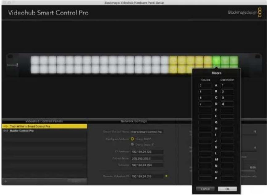
Up to 16 crosspoint routes can be changed by a single macro.
Take Button
When the Enable Take Button checkbox is active, the lower right button on the control interface turns red. Use this if you want a confirmation option to come up before your route change takes place. Press the red take button to confirm your route change. The take button can be used with both Cut-Bus and XY controller configurations and can also be used with macros.
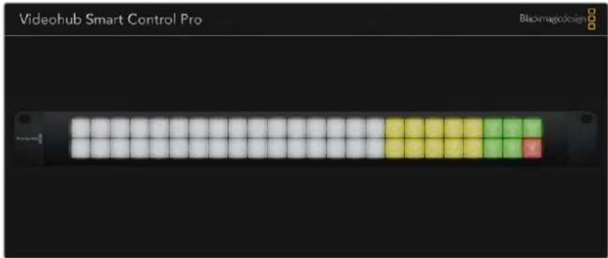
The Take button illuminates red in the lower right corner.
Backlight
Adjust the backlight slider to vary the brightness of the backlit buttons as desired. Enable Backlight Destinations Only if you wish to disable the backlighting of the white source buttons.
Configuring GPIs
The GPI and Tally Interface has 8 GPIs that provide crosspoint switching. In the example on the left, if GPI 1 detects a contact closure it will switch Input 12 on your Videohub to Output 1. This means when you switch the joystick control on your CCU, video going to Input 12 of your Videohub will be previewed on your monitor.
The crosspoints can be configured in the Videohub Hardware Panel Setup simply by clicking inside the Input and Output fields on the diagram and typing in the Input or Output number.
The Videohub Control Settings pane offers two ways to preview the output from your Videohub.
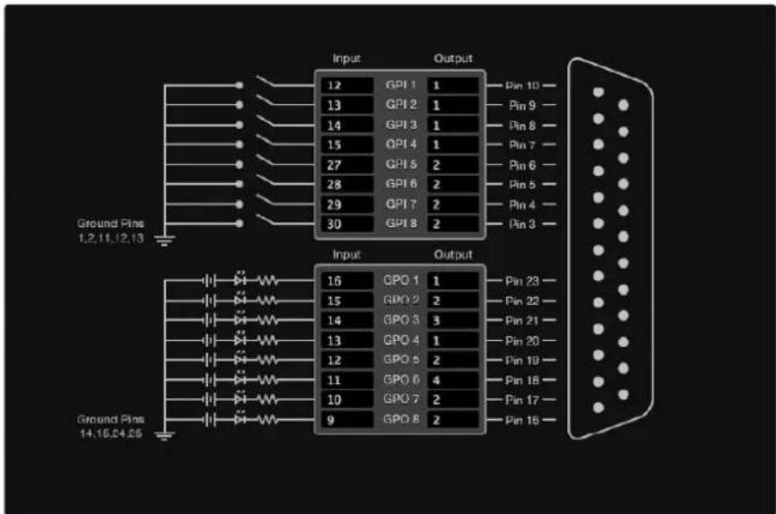
Click inside the diagram to change inputs and outputs for GPI crosspoint switching and Tally.
Latch Video
If you want the output to stay as selected, choose Latch Video. This means you can press the switch once on your CCU and the input from the selected crosspoint will stay on your monitor until another crosspoint is selected.
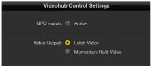
Select Latch Video if you want your preview to hold until another crosspoint is selected. Choose Momentary Hold Video if you want your preview to revert back to the previous crosspoint when you release the control switch.
Momentary Hold Video
Select this option if you want the output to return to the previous input after you let go of the switch or joystick control on your CCU. For example, when you press and hold your switch, Input 13 might be previewed, but will return to displaying Input 12 on your monitor once you release the switch.
Configuring Tally
Tally is usually a lamp on the front of a camera to indicate that it is on air, but it's a useful visual indicator and can be used on any equipment to indicate activity and doesn't have to be used specifically with cameras.
The GPI and Tally Interface has 8 configurable GPOs, which send a tally signal to your cameras or other devices under certain crosspoint conditions. In the example on the left, GPO 1 is configured so that when Input 16 on the Videohub is routed to Output 1, GPO 1 will be activated.
The crosspoints can be configured in Videohub Hardware Panel Setup simply by clicking inside the Input and Output fields on the diagram.
GPO Match
Enable the GPO match checkbox to replicate the configuration of your crosspoints from GPIs to GPOs. This can be useful if you want to see a tally light activate when changing routes for your GPIs.
When this checkbox is enabled, the GPO half of the diagram will be grayed out and cannot be edited until the GPO match checkbox is disabled.
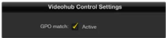
Enable the GPO match checkbox to replicate the crosspoint configuration of your GPIs.
Daisy Chaining Multiple GPI and Tally Interfaces
The GPI and Tally Interface supports 8 GPIs and 8 GPOs at a time, which should be enough for most live television situations. However, if you have more than 8 cameras then you may want to daisy chain a second or third GPI and Tally Interface.
The GPI and Tally Interface has two ethernet ports so that you can connect one port to a Videohub and use the other port to link other GPI and Tally Interfaces together.
1 Connect power to the first GPI and Tally Interface.
2 Connect a standard RJ45 ethernet cable from your Videohub or network to the ethernet IN port on the GPI and Tally Interface.
3 Connect power to the second GPI and Tally Interface.
4 Connect a standard RJ45 ethernet cable from the ethernet OUT of the first GPI and Tally Interface to the ethernet IN port on the second GPI and Tally Interface.
This can be repeated for as many GPI and Tally Interfaces as you need as long as power is supplied to all units in the chain.
Sometimes it can get confusing to know which GPI and Tally Interface you are working with when you have several connected. Select the GPI and Tally Interface in the Videohub Control Panels pane and click the Identify button. The LED next to the ethernet IN port on the selected device will light up.
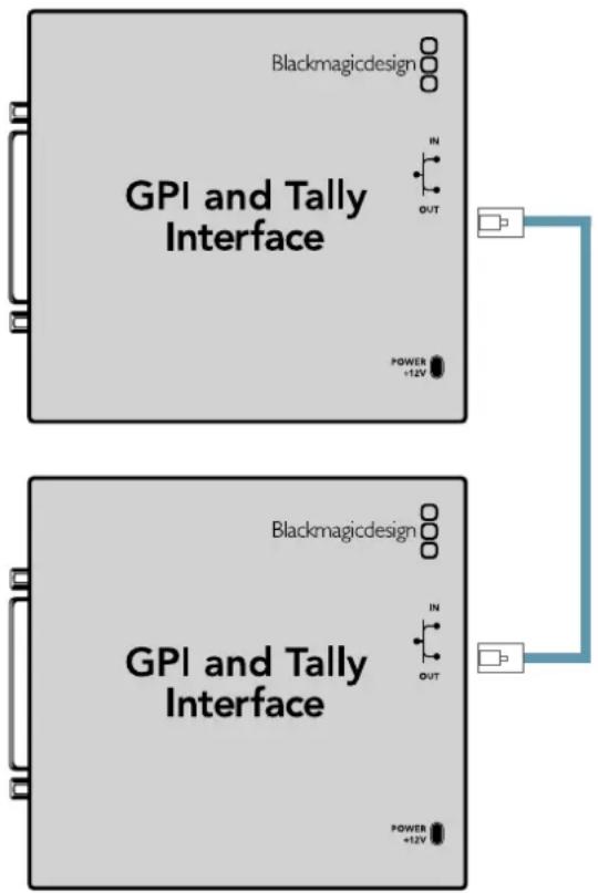
Daisy chain multiple GPI and Tally Interfaces using ethernet. Power must be supplied to each individual unit in the chain.
Adding a GPI and Tally Interface Over a Network
You may want to configure a second GPI and Tally Interface but it may be in another location and only accessible over a network. You can add it to your list manually by entering its IP address into Videohub Hardware Panel Setup.
If you do not know the IP address of the GPI and Tally Interface you want to add, connect it to a computer with USB, open Videohub Hardware Panel Setup and note down the IP address in the Network Settings tab.
If you do not have access to the unit because it is in another location, you can find it on the network using the Bonjour browser. This application will show you all the devices on your network and will give you the IP address of the GPI and Tally Interface you wish to add.
1 Press the + (add device) button at the bottom of the Videohub Control Panels pane.
2 Type in the IP address of the GPI and Tally Interface and press OK.
3 The second GPI and Tally Interface will appear in the list with any other devices that are connected to the Videohub.
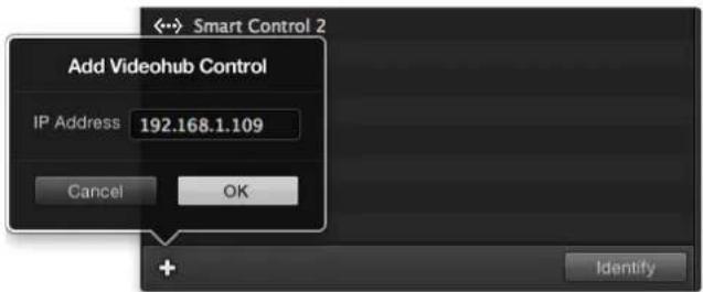
Press the + (add device) button and enter the IP address of a GPI and Tally Device you want to add. Press the Identify button to activate the LED on a selected GPI and Tally Interface.
Setting up the GPI and Tally Interface
The GPI and Tally Interface is configured using the Videohub Hardware Panel Setup. Before you can use the GPI and Tally Interface, you may need to install the latest version of the software.
1 Connect the power adapter to the GPI and Tally Interface.
2 Connect the GPI and Tally Interface to your computer with a USB Type A to B cable.
3 Open the software and it will detect whether your GPI and Tally Interface has been configured for a Videohub before. If it has the software will open without any need for changes. Otherwise a message will tell you your GPI and Tally Interface has been configured for use with an ATEM Switcher and will need to be reconfigured for use with Videohub. Click Yes. After a few moments the GPI and Tally Interface will be reconfigured as a Videohub client.
Configuring the GPI and Tally Interface
If your Videohub does not have an Ethernet port, or if it is only accessible over a network:
1 Connect a USB type A to B cable from your GPI and Tally Interface to your computer.
2 Connect an Ethernet cable from the Ethernet IN port on your GPI and Tally Interface to your Ethernet switcher.
3 Open Videohub Hardware Panel Setup.
4 You should see your GPI and Tally Interface with a USB icon next to it in the Videohub Control Panels pane. Give your GPI and Tally Interface a unique name so it can be easily recognized. To do so, click inside the GPI and Tally Name field and type a name.
5 Check the option to configure your IP address as 'using DHCP' or 'static IP'. Depending on your setup, you may choose either so it's probably a good idea to check with your network administrator to see which is the better option.
6 In the Remote Videohub IP field, enter the IP address of the Videohub you want to connect to. A red light next to the field will turn green and the LED on the GPI and Tally interface will illuminate when a connection has been established.
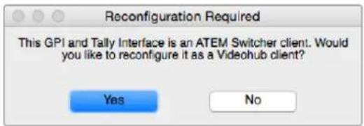
You will need to reconfigure your GPI and Tally Interface to work with Videohub.
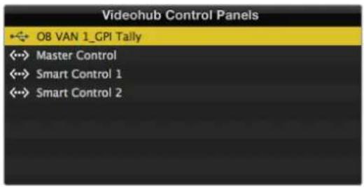
GPI and Tally Interface connected via USB.
If you do not know the IP address of your Videohub:
1 Connect the Videohub to your computer via USB.
2 Launch the Videohub software and click on Videohub Server Preferences.
3 Note down the IP address in the Remote Videohub IP address field.
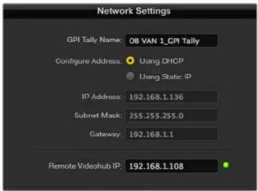
Enter a GPI and Tally Name and the IP address of the Videohub you want to connect to.
Controlling Blackmagic MultiView 16 with Videohub Software
Blackmagic MultiView 16 can be controlled using Videohub Control software. Blackmagic Multiview 16 is a single rack SDI monitoring solution capable of simultaneously displaying up to 16 Ultra HD, HD and SD SDI signals in a variety of formats on a single monitor. With Videohub Control you get the ability to route Blackmagic MultiView 16's multi view sources and views, and arrange them on a display the way you want, so is the perfect monitoring choice for your Videohub router workflow.
Up to 16 video signals can be displayed using the maximum 4x4 grid, or you can select 3x3, 2x2, or view each input in full screen mode by selecting solo. When connected to an Ultra HD monitor, Blackmagic MultiView 16 can even display four HD signals in their native 1080 HD resolution.
Connecting Blackmagic MultiView 16 to Videohub Control Software
It's easy to connect Blackmagic MultiView 16 to your Videohub software:
1 Ensure Blackmagic MultiView 16 has the latest internal software installed and you are running the latest version of Videohub Control. You can download the latest updates from the Blackmagic Design support center at: www.blackmagicdesign.com/support
2 Power your Blackmagic MultiView 16.
3 Plug Blackmagic MultiView 16 into your computer via Ethernet.
4 Launch Blackmagic Videohub Control.
5 Click on the 'select a Videohub' button on the Videohub Control home page and select your Blackmagic MultiView 16 from the list.
Controlling your Blackmagic MultiView 16 using Videohub Control software is an easy and convenient way to change sources and views, and arrange your view displays remotely, while monitoring multiple inputs at the highest video resolution available.
If you can't see your Blackmagic MultiView 16 in the list of Videohubs available, you may need to configure the IP address for your network.
For more information, refer to 'Configuring Network Settings on Blackmagic MultiView 16' below.
Configuring Network Settings on Blackmagic MultiView 16
Use Blackmagic MultiView 16's integrated control panel and LCD to set the IP address and network settings. Once these settings are set correctly, your Blackmagic MultiView 16 will be visible to other computers and hardware panels. These devices can then control the unit remotely and make routing changes.


natural_image
Front view of a network switch or rack with multiple ports and connectors (no visible text or labels)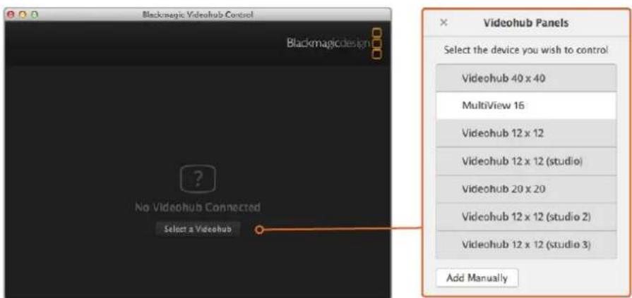
Connect to Blackmagic Videohub Control software by clicking on the 'select a Videohub' button, then select your Blackmagic MultiView 16 from the list.
To configure your network settings:
1 Press the 'menu' button and turn the rotary knob to highlight the 'networking' tab.
2 Press the 'set' button to enter the 'network settings' page.
3 Turn the rotary knob to select the 'IP address' tab.
4 Press the 'set' button to highlight the first field of the IP address. You can use either the rotary knob or numbered pushbuttons to enter values.
5 Press 'set' to confirm the first field of the IP address, then repeat the above step for the next three fields until you have set the desired IP address. If you need to assign the Subnet and Gateway address, they can be set using the same method.
6 Press the 'menu' button twice to return to the home screen.
For more information on how to use Blackmagic MultiView 16 with Blackmagic Videohub Control software, refer to the Blackmagic MultiView 16 instruction manual. You can find the latest manual and product updates at the Blackmagic Design support center at: www.blackmagicdesign.com/support
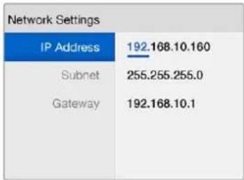
bar
Network Settings | Category | Value | |---|---| | IP Address | 192.168.10.160 | | Subnet | 255.255.255.0 | | Gateway | 192.168.10.1 |Use the rotary knob or the number buttons on Blackmagic MultiView 16's control panel to assign values to your network settings.
Developer Information
Blackmagic Videohub Ethernet Protocol v2.3
Summary
The Blackmagic Videohub Ethernet Protocol is a text based protocol that is accessed by connecting to TCP port 9990 on a Videohub Server. Integrated Videohub Servers and Videohub Server computers are supported by the protocol.
The Videohub Server sends information in blocks which each have an identifying header in all-caps, followed by a full-colon. A block spans multiple lines and is terminated by a blank line. Each line in the protocol is terminated by a newline character.
Upon connection, the Videohub Server sends a complete dump of the state of the device. After the initial status dump, status updates are sent every time the Videohub status changes.
To be resilient to future protocol changes, clients should ignore blocks they do not recognize, up to the trailing blank line. Within existing blocks, clients should ignore lines they do not recognize.
LEGEND
← line feed or carriage return
... and so on
Version 2.3 of the Blackmagic Videohub Ethernet Protocol was released with Videohub 4.9.1 software.
Protocol Preamble
The first block sent by the Videohub Server is always the protocol preamble:
PROTOCOL PREAMBLE:←
Version: 2.3←
The version field indicates the protocol version. When the protocol is changed in a compatible way, the minor version number will be updated. If incompatible changes are made, the major version number will be updated.
Device Information
The next block contains general information about the connected Videohub device. If a device is connected, the Videohub Server will report the attributes of the Videohub:
VIDEOHUB DEVICE:←
Device present: true←
Model name: Blackmagic Smart Videohub←
Video inputs: 16←
Video processing units: 0←
Video outputs: 16←
Video monitoring outputs: 0←
Serial ports: 0←
This example is for the Smart Videohub which is a 16x16 router.
If the Videohub Server has no device connected, the block will simply be:
VIDEOHUB DEVICE:←
Device present: false←
If a device is present, but has an incompatible firmware, the status reported will be:
VIDEOHUB DEVICE:←
Device present: needs _ update←
In the last two situations, no further information will be sent, unless the situation is rectified.
If the Videohub Server detects a new Videohub attached, it will resend all blocks except the protocol preamble to indicate the device has changed, and allow the client to update its cache of server state.
Initial Status Dump
The next four blocks enumerate the labels assigned to the input, output, monitoring and serial ports.
Videohubs that do not have monitoring or serial ports do not send the corresponding blocks.
INPUT LABELS:
0 VTR 1
1 VTR 2
...
OUTPUT LABELS:
0 Output feed 1
1 Output feed 2
...
MONITORING OUTPUT LABELS:
0 Monitor feed 1
1 Monitor feed 2
...
SERIAL PORT LABELS:
0 Deck 1
1 Deck 2
NOTE Ports are always numbered starting at zero in the protocol which matches port one on the chassis.
The next three blocks describe the routing of the output, monitoring and serial ports.
VIDEO OUTPUT ROUTING←
0 5←
1 3←
...
←
VIDEO MONITORING OUTPUT ROUTING:←
0 7←
1 8←
...
←
SERIAL PORT ROUTING:←
0 12←
1 11←
...
←
Videohubs with processing units (only the Workgroup Videohub) send an extra routing block:
PROCESSING UNIT ROUTING
0 5
1 3
...
←
Videohubs with frame buffers (only the Workgroup Videohub) send two extra blocks:
FRAME LABELS:←
0 Frame one←
1 Frame two←
...
←
FRAME BUFFER ROUTING:←
0 7←
1 8←
...
←
The next three blocks describe the locking status of the output, monitoring and serial ports.
Each port has a lock status of "O" for ports that are owned by the current client (i.e., locked from the same IP address), "L" for ports that are locked from a different client, or "U" for unlocked.
Note that Videohubs that do not have monitoring ports or serial ports do not send the corresponding blocks.
VIDEO OUTPUT LOCKS:←
0 U←
1 U←
...
←
MONITORING OUTPUT LOCKS:←
0 U←
1 U←
...
←
SERIAL PORT LOCKS:←
0 U←
1 U←
...
←
Videohubs with processing units (only the Workgroup Videohub) send an extra lock block:
PROCESSING UNIT LOCKS:←
0 U←
1 U←
...
←
Videohubs with frame buffers (only the Workgroup Videohub) send an extra lock block:
FRAME BUFFER LOCKS:←
0 U←
1 U←
...
←
Videohubs with serial ports next send a block which describes the direction of each serial port. Each port has a direction of either “control” for the “In (Workstation)” setting, “slave” for “Out (Deck)”, or “auto” for “Automatic”.
SERIAL PORT DIRECTIONS:
0 control
1 slave
2 auto
...
←
Videohubs with pluggable cards (only Universal Videohubs) send three more blocks that describe the hardware status of the ports. Missing video or serial ports have a status of "None"; input and output video ports will be "BNC" or "Optical" if they are present; serial ports will be "RS422" if they are present.
VIDEO INPUT STATUS:←
0 BNC←
1 BNC←
...
←
VIDEO OUTPUT STATUS:←
0 BNC←
1 BNC←
...
←
SERIAL PORT STATUS:←
0 RS422←
1 RS422←
...
←
Status Updates
When any route, label, or lock is changed on the Videohub Server by any client, the Videohub Server resends the applicable status block, containing only the items that have changed. For example, if serial port 6 has been unlocked, the following block will be sent:
SERIAL PORT LOCKS:←
5 U←
←
If multiple items are changed, multiple items may be present in the update:
OUTPUT LABELS←
7 New output 8 label←
10 New output 11 label←
←
If a card is plugged into or removed from the Universal Videohub, it will send hardware status blocks for the video inputs, video outputs, and serial ports on that card.
Requesting Changes
To update a label, lock or route, the client should send a block of the same form the Videohub Server sends when its status changes. For example, to change the route of output port 8 to input port 3, the client should send the following block:
VIDEO OUTPUT ROUTING←
7 2←
←
The block must be terminated by a blank line. On receipt of a blank line, the Videohub Server will either acknowledge the request by responding:
ACK←
←
or indicate that the request was not understood by responding:
NAK←
←
After a positive response, the client should expect to see a status update from the Videohub Server showing the status change. This is likely to be the same as the command that was sent, but if the request could not be performed, or other changes were made simultaneously by other clients, there may be more updates in the block, or more blocks. Simultaneous updates could cancel each other out, leading to a response that is different to that expected.
In the absence of simultaneous updates, the dialog expected for a simple label change is as follows:
OUTPUT LABELS
6 new output label seven
ACK
OUTPUT LABELS
6 new output label seven
The asynchronous nature of the responses means that a client should never rely on the desired update actually occurring and must simply watch for status updates from the Videohub Server and use only these to update its local representation of the server state.
To lock a port, send an update to the port with the character "O" indicating that you wish to lock the port for example:
SERIAL PORT LOCKS:←
7 0←
←
ACK←
←
SERIAL PORT LOCKS:←
7 0←
←
To forcibly unlock a port that has been locked by another client, send an update to the port with the character "F" instead of using the usual unlock character "U". For example, to override a lock on port 7:
SERIAL PORT LOCKS:←
7 F←
←
ACK←
←
SERIAL PORT LOCKS:←
7 U←
←
Hardware status blocks can only be sent by the Videohub Server. If a client sends hardware status blocks, they will be ignored.
Requesting a Status Dump
The client may request that the Videohub Server resend the complete state of any status block by sending the header of the block, followed by a blank line. In the following example, the client requests the Videohub Server resend the output labels:
OUTPUT LABELS
ACK
OUTPUT LABELS
0 output label 1
1 output label 2
2 output label 3
...
Checking the Connection
While the connection to the Videohub Server is established, a client may send a special no-operation command to check that the Videohub Server is still responding:
PING:
If the Videohub Server is responding, it will respond with an ACK message as for any other recognized command.
Videohub RS-422 Protocol
General
The RS-422 protocol can be used to control many Videohub models as RS-422 slave devices, for router crosspoint switching. This feature is available on any Videohub model with an "RS-422 Control" port.
Depending on your model of Videohub, the RS-422 port may be either a DB9 or RJ11 connector. DB9 cables are commonly available in electrical stores. The RJ11 connector is the same used in many landline telephone connections. By modifying an RS-422 to USB adapter cable terminated with an RJ11 connector you can control Videohub using external controllers via USB.
In "Leitch Server" mode, these Videohub models implement the router (server) side of the Leitch Serial Pass-Through Protocol as specified in section 4 of Leitch document SPR-MAN revision D. In "Leitch Client" mode, the Videohub implements the controller (client) side of the Leitch terminal protocol.
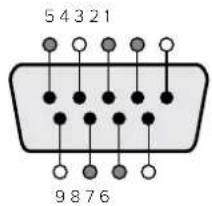
| Pln Function | |
| 1 Ground | |
| 2 Tx- (Data sent by router) | |
| 3 Rx+ (Data received by router) | |
| 4 Ground | |
| 5 NC (No connect) | |
| 6 Ground | |
| 7 Tx+ (Data sent by router) | |
| 8 Rx- (Data received by router) | |
| 9 Ground | |
Videohub RS-422 Router Control DB9 pin connections.
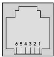
| Pin No. Function | |
| Pin 1 | TX + |
| Pin 2 | TX - |
| Pin 3 | GND |
| Pin 4 | GND |
| Pin 5 | RX - |
| Pin 6 | RX + |
Videohub RS-422 Router Control RJ11 pinout diagram.
This document describes the commands and parameters in the protocol that are relevant and supported by Videohub. Other commands and parameters specified in the Leitch protocol are accepted but ignored.
The RS-422 serial port is configured as 9600 N81.
The protocol is line-oriented, with a maximum length of 250 characters per command. Each command from the client should be terminated with a carriage-return ( r ). Each response from the server will be terminated with a carriage-return and line-feed ( r n ).
Sources, destinations and levels are always specified in base-16, numbered from zero. Levels are always between 0 and 15 ("F"). Videohubs only have one valid level - level zero.
On connecting to the serial port, the client should send a carriage-return. The Videohub Server will respond with a > character prompt, which is not followed by a carriage-return or line-feed. Receiving the prompt indicates that a connection has been established. The same prompt will be issued after each command received by the Videohub Server.
In the following documentation, commands in orange and values in blue must be typed literally, including any spaces. In the following example of an immediate command using destination port 7 and source port 3, @ X:0/destination,source would be entered as: @ X:0/6,2
Notifications
Once connected, if status reporting is enabled, the client will receive a notification message when a route changes on the Videohub Server. The notifications take one of two forms:
S:0destination,source Routing change
This message indicates that the specified source port is now routed to the specified destination.
V:0destination,source Preset routing notification
This message indicates that the current preset includes a route from the specified source to the specified destination.
Global Commands
All pass-through commands are preceded by an Ⓞ symbol and a space.
The following client commands are supported:
@ ! disable status reporting
Status reporting is disabled by default.
@ ? enable status reporting
Status reporting is enabled.
@ Z: reset routing table
Routing is reset so that the first source is routed to all destinations.
Immediate Commands
@ X:0/destination,source change route
@ X:0/destination,source/destination-2,source-2... change multiple routes
The specified source ports are routed to the specified destinations.
Any routing changes will trigger s: notifications
@ X?0destination request individual route status
The source routed to a the specified destination will be returned as an s: notification.
@ S?0 request all ports route status
Each source & destination port pair will be returned as s: notifications
Salvo Commands
@ P:0/destination,source queue route change
@ P:0/destination,source/destination-2,source-2... queue multiple route changes
The specified routing changes are added to the current salvo for later execution.
@ P?0destination request individual port status in salvo
If a routing change for the specified destination port is queued, the route will be returned as a v: notification.
@ v?0 request all ports status in salvo
Each queued routing change in the salvo is reported as a v: notification.
@ B:C clear salvo
@ B:R clear salvo
Any queued changes are discarded and the salvo is reset.
@ B:E execute salvo
Any queued changes are executed and each routing change will be returned as an notification.
Saving and Loading Labels with Telnet in Mac OS
Normally you would use Blackmagic Videohub Setup to save and load labels between different Videohub routers and to backup your videohub settings. However, if for any reason you wish to use the Terminal, the instructions below let you save and load router label configurations via the Terminal.
![Blackmagics-iMac:~ timf$ telnet 192.168.25.253 9990 Trying 192.168.25.253... Connected to 192.168.25.253. Escape character is '^]'. PROTOCOL PREAMBLE: Version: 2.4 VIDEOHUB DEVICE: Device present: true Model name: Blackmagic Smart Videohub Unique ID: 7c2e0d0106df Video inputs: 16 Video processing units: 0 Video outputs: 16 Video monitoring outputs: 0 Serial ports: 0 INPUT LABELS: 0 Camera 1 1 Mini Converter 1 2 Hyperdeck 1 3 VTR 1 4 Teranex 1 5 PC Workstation 6 ATEM PGM 7 Camera 2 8 Mini Converter 2 9 Mac Workstation 10 Hyperdeck 2 11 VTR 2 12 Teranex 3 13 Hyperdeck 3 14 Hyperdeck 3 15 Input 16 OUTPUT LABELS: 0 Main Monitor 1 1 Main Monitor 2 2 Audio Monitor 1 3 Audio Monitor 2 4 ATEM Input 1 5 ATEM Input 2 6 ATEM Input 3 7 Hyperdeck 4 8 Hyperdeck 5 9 Hyperdeck 3 10 VTR 3 11 VTR 4 12 Teranex 4 13 Ultrascope 1 14 Ultrascope 2 15 Ultrascope 3](/content/2026/05/813338/images/e0661e7aad3f8826c6aa5c6d475cc7b3744c97bf9eacac9b0c1829584df18bc4.jpg)
Saving Labels
1 Open the Terminal application which is located within the Applications > Utilities folder.
2 Type in "telnet" and a space followed by the IP of your Videohub, then another space and "9990", which is the default port number. For example type: telnet 192.168.25.253 9990. The Protocol Preamble screen will appear.
3 Copy the INPUT LABELS: text including the heading and paste into a word processor or simple text editor. Name this file "input labels" and save to your favorite location.
4 Copy the OUTPUT LABELS: text including the heading and paste into a word processor or simple text editor. Name this file "output labels" and save to your favorite location.
5 Close the telnet session by exiting the terminal window.
Loading Labels
1 Open the Terminal application with is located within the Applications > Utilities folder.
2 Type in "telnet" and a space followed by the IP of your Videohub, then another space and "9990", which is the default port number. For example type: telnet 192.168.25.253 9990. The Protocol Preamble screen will appear.
3 Open the "input labels" text file in your text editing program and copy the INPUT LABELS: text.
4 Paste this into the telnet session and press "return" twice. Telnet will respond with "ACK" and Videohub will update the input labels.
5 Open the "output labels" text file in your text editing program and copy the OUTPUT LABELS; text.
6 Paste this into the telnet session and press "return" twice. Telnet will respond with "ACK" and Videohub will update the output labels.
7 Close the telnet session by exiting the terminal window.
Saving and Loading Labels with Telnet in Windows
While you can save and load labels within Blackmagic Videohub Setup, you may also download and use PuTTY which is a free telnet client.
Setting up PuTTY
1 Start the application and in the "Host Name" field, type the IP of your Videohub and in the "Port" field type "9990", which is the default port number.
2 From the Connection type options select the "Telnet" radio button.
3 Select the "Terminal" tab and tick the "Implicit CR in every LF" checkbox.
4 Click the "Session" tab and save your session parameters by entering a name in the "Saved Sessions" field and clicking the "Save" button.
Saving Labels
1 Double click the PuTTY icon to start the application. Select your saved session from the list and click the "Load" button followed by the "Open" button. The Protocol Preamble screen will appear.
2 Copy the INPUT LABELS: text including the heading and paste into a word processor or simple text editor. Name this file "input labels" and save to your favorite location.
3 Copy the OUTPUT LABELS: text including the heading and paste into a word processor or simple text editor. Name this file "output labels" and save to your favorite location.
4 Exit the telnet session by closing the PuTTY window.
Loading Labels
1 Double click the PuTTY icon to start the application. Select your saved session from the list and click the "Load" button followed by the "Open" button. The Protocol Preamble screen will appear.
2 Open the "input labels" text file in your text editing program and copy the INPUT LABELS: text.
3 Right click in the PuTTY session to paste the copied section and press "Enter" twice. PuTTY will respond with "ACK" and Videohub will update the input labels.
4 Open the "output labels" text file in your text editing program and copy the OUTPUT LABELS: text.
5 Right click in the PuTTY session to paste the copied section and press "Enter" twice. PuTTY will respond with "ACK" and Videohub will update the output labels.
6 Exit the telnet session by closing the PuTTY window.
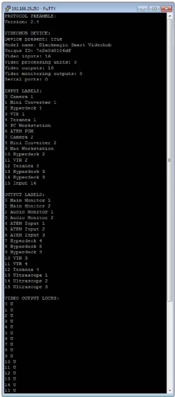
Help
Replacing a fan in Universal Videohub
Each fan is designed to be replaced without needing to switch off power to Videohub.
1 Locate the fan tray at the base of the unit.
2 Using a number 01 Phillips head screwdriver, remove the left and right screws from the fan tray.
3 While supporting the tray, remove the center screw.
4 Having removed all three screws, slowly allow the fan tray to swing open until you see the black plastic dust filter on top of each fan.
5 Gently pull the tray towards you while continuing to swing it down until you feel the rear of the tray detach from the Universal Videohub chassis. Note which fan is faulty.
6 You will see the colored power cables connected to each fan. Each fan power cable connects to the Videohub motherboard with a plastic connector. While supporting the fan tray, unplug the plastic power connectors of all three fans. The fan tray can now be fully removed.
7 Place the fan tray on a flat surface and unclip the top of the dust-filter housing using the four clips.
8 Remove the top of the housing and the filter. Four screws will be revealed. Remove the four screws around the faulty fan. Then remove the base of the dust filter housing and also the faulty fan.
9 Replace the fan with a spare unit and then reinstate the base of the dust filter housing. Secure the housing and fan with the four screws and ensure the heads of the screws recess into the dust filter housing. If the screws fail to recess, flip over the housing and try again.
10 Place the dust filter over the base of the housing and then snap on the top of the dust filter housing.
11 Position the fan tray underneath the base of the Universal Videohub chassis and connect all three fan power cables to the motherboard. All three fans should immediately start running.
12 Gently dock the rear of the fan tray with the Universal Videohub chassis. Swing up the front of the fan tray and simultaneously push the tray towards the Videohub motherboard until the rear of the fan tray slides into place and the front swings shut.
13 Reinstall the three screws.
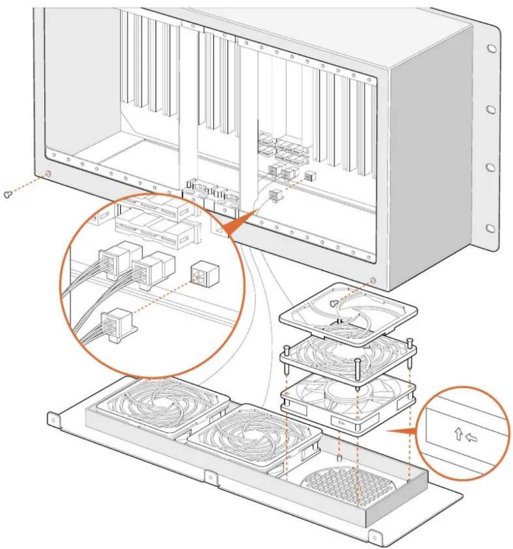
Replacing the fan in Broadcast Videohub
The Broadcast Videohub package include a spare fan in case the pre-installed fan stops working or becomes noisy. Videohub will continue to work even if the fan stops running. However, a working fan will help to extend the life of the Videohub for many years and we recommend the fan be replaced if it should ever stop running.
The fan is designed to be replaced without needing to switch off power to Videohub.
1 Remove the four screws on the fan cover and lift up the cover gently.
2 You will see the colored power cables connecting to a plug on Videohub. Gently remove the plastic plug.
3 Remove the two screws that attach the faulty fan to the fan cover.
4 Replace the faulty fan with the spare fan by following this process in reverse. The spare fan should immediately start running.
Tips for Connecting SDI cables
The weight of copper-based SDI cables quickly adds up so it is advisable to use your rack to support the cables so that the full cable weight does not place undue stress on the BNC ports of your Videohub. This is particularly important with larger models of Videohub due to the weight of many SDI cables. Tying cable harnesses to the rack frame can provide support for large volumes of cabling.
It is also good practice to attach cables to the lowest BNC and optical fiber connectors first and then work upwards. This will avoid having to push lots of cables out of the way as you attach more cables in the future.
All Videohub models feature regular sized BNC ports, which make it easy to connect to other SDI equipment using regular SDI cables.
If you're connecting Videohub to SDI equipment that has miniature SDI connectors, such as DIN 1.0/2.3, we recommend using SDI cables that are terminated with a miniature connector at one end and a regular BNC at the other. Alternatively, an adapter cable can be connected to a regular SDI cable but this could prevent you from running long cables due to some loss of signal quality.
It's easy to connect and disconnect SDI cables to and from your Videohub.
However as you attach more SDI cables, you might find it tricky to fit your fingers between the BNC connectors. You can use an inexpensive BNC removal tool, from third party vendors, to help make this task easy even when your Videohub has many cables connected.
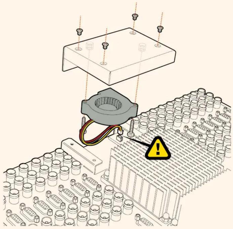
natural_image
Technical illustration of an electronic component assembly with a warning symbol (no text or labels present)Getting Help
The fastest way to obtain help is to go to the Blackmagic Design online support pages and check the latest support material available for your Blackmagic Design Videohub Control.
Blackmagic Design online support pages
The latest manual, software and support notes can be found at the Blackmagic Design support center at www.blackmagicdesign.com/support.
Contacting Blackmagic Design support
If you can't find the help you need in our support material, please use the "Send us an email" button to email a support request. Alternatively, click on the "Find your local support team" button and call your nearest Blackmagic Design support office.
Checking the version currently installed
To check which version of Videohub Control is installed on your computer, open the Blackmagic Videohub Control application. From the Blackmagic Videohub Control menu, select About Blackmagic Videohub and note the version number.
How to get the latest updates
After checking the version of your Blackmagic Videohub Control on your computer, please visit the Blackmagic Design support center at www.blackmagicdesign.com/support to check for the latest updates. While it is usually a good idea to run the latest updates, it is a wise practice to avoid updating any software if you are in the middle of an important project.
Regulatory Notices

Disposal of Waste of Electrical and Electronic Equipment Within the European Union.
The symbol on the product indicates that this equipment must not be disposed of with other waste materials. In order to dispose of your waste equipment, it must be handed over to a designated collection point for recycling. The separate collection and recycling of your waste equipment at the time of disposal will help conserve natural resources and ensure that it is recycled in a manner that protects human health and the environment. For more information about where you can drop off your waste equipment for recycling, please contact your local city recycling office or the dealer from whom you purchased the product.

This equipment has been tested and found to comply with the limits for a Class A digital device, pursuant to Part 15 of the FCC rules. These limits are designed to provide reasonable protection against harmful interference when the equipment is operated in a commercial environment. This equipment generates, uses, and can radiate radio frequency energy and, if not installed and used in accordance with the instructions, may cause harmful interference to radio communications. Operation of this product in a residential area is likely to cause harmful interference, in which case the user will be required to correct the interference at personal expense.
Operation is subject to the following two conditions:
1 This device may not cause harmful interference.
2 This device must accept any interference received, including interference that may cause undesired operation.
ICES-3 (A) NMB-3 (A)
ISED Canada Statement
This device complies with Canadian standards for Class A digital apparatus.
Any modifications or use of this product outside its intended use could void compliance to these standards.
Connection to HDMI interfaces must be made with high quality shielded HDMI cables.
This equipment has been tested for compliance with the intended use in a commercial environment. If the equipment is used in a domestic environment, it may cause radio interference.
Safety Information
For protection against electric shock, the equipment must be connected to a mains socket outlet with a protective earth connection. In case of doubt contact a qualified electrician.
To reduce the risk of electric shock, do not expose this equipment to dripping or splashing.
Product is suitable for use in tropical locations with an ambient temperature of up to 40 °C.
Ensure that adequate ventilation is provided around the product and that it is not restricted.
When rack mounting, ensure that the ventilation is not restricted by adjacent equipment.
No operator serviceable parts inside product. Refer servicing to your local Blackmagic Design service center.
Some products have the facility to connect small form-factor transceiver (SFP) optical fibre modules. Only use Laser class 1 optical SFP modules.
Recommended Blackmagic Design SFP modules:
- 3G-SDI: PL-4F20-311C

Use only at altitudes not more than 2000m above sea level.
State of California statement
This product can expose you to chemicals such as trace amounts of polybrominated biphenyls within plastic parts, which is known to the state of California to cause cancer and birth defects or other reproductive harm. For more information go to www.P65Warnings.ca.gov.
Warning for Authorized Service Personnel
The DC power supplied to operate the Universal Videohub 72 and Universal Videohub 288 is considered an energy hazard. Shorting of components or tracks using a conductive part can result in arcing. Ensure power is disconnected before servicing that involves access to the racks.

The equipment must be installed within a restricted access location such as a controlled room for service personnel only.
No more than 60 Universal Videohub Optical Cards can be installed into the Universal Videohub 288.
Disconnect power from both power inlets before servicing!
Caution — Double Pole/ Neutral Fusing
The power supply contained in this equipment has a fuse in both line and neutral conductors and is suitable for connection to the IT power distribution system in Norway.
Warranty
Limited Warranty
Blackmagic Design warrants that Videohub routers will be free from defects in materials and workmanship for a period of 36 months from the date of purchase excluding connectors, cables, cooling fans, fiber optic modules, fuses, keyboards and batteries which will be free from defects in materials and workmanship for a period of 12 months from the date of purchase. Blackmagic Design warrants that Videohub Master Control and Videohub Smart Control will be free from defects in materials and workmanship for a period of 12 months from the date of purchase. If a product proves to be defective during this warranty period, Blackmagic Design, at its option, either will repair the defective product without charge for parts and labor, or will provide a replacement in exchange for the defective product.
In order to obtain service under this warranty, you the Customer, must notify Blackmagic Design of the defect before the expiration of the warranty period and make suitable arrangements for the performance of service. The Customer shall be responsible for packaging and shipping the defective product to a designated service center nominated by Blackmagic Design, with shipping charges pre paid. Customer shall be responsible for paying all shipping changes, insurance, duties, taxes, and any other charges for products returned to us for any reason.
This warranty shall not apply to any defect, failure or damage caused by improper use or improper or inadequate maintenance and care. Blackmagic Design shall not be obligated to furnish service under this warranty: a) to repair damage resulting from attempts by personnel other than Blackmagic Design representatives to install, repair or service the product, b) to repair damage resulting from improper use or connection to incompatible equipment, c) to repair any damage or malfunction caused by the use of non Blackmagic Design parts or supplies, or d) to service a product that has been modified or integrated with other products when the effect of such a modification or integration increases the time or difficulty of servicing the product. THIS WARRANTY IS GIVEN BY BLACKMAGIC DESIGN IN LIEU OF ANY OTHER WARRANTIES, EXPRESS OR IMPLIED. BLACKMAGIC DESIGN AND ITS VENDORS DISCLAIM ANY IMPLIED WARRANTIES OF MERCHANTABILITY OR FITNESS FOR A PARTICULAR PURPOSE. BLACKMAGIC DESIGN'S RESPONSIBILITY TO REPAIR OR REPLACE DEFECTIVE PRODUCTS IS THE WHOLE AND EXCLUSIVE REMEDY PROVIDED TO THE CUSTOMER FOR ANY INDIRECT, SPECIAL, INCIDENTAL OR CONSEQUENTIAL DAMAGES IRRESPECTIVE OF WHETHER BLACKMAGIC DESIGN OR THE VENDOR HAS ADVANCE NOTICE OF THE POSSIBILITY OF SUCH DAMAGES. BLACKMAGIC DESIGN IS NOT LIABLE FOR ANY ILLEGAL USE OF EQUIPMENT BY CUSTOMER. BLACKMAGIC IS NOT LIABLE FOR ANY DAMAGES RESULTING FROM USE OF THIS PRODUCT. USER OPERATES THIS PRODUCT AT OWN RISK.
© Copyright 2020 Blackmagic Design. All rights reserved. 'Blackmagic Design', 'DeckLink', 'HDLink', 'Workgroup Videohub', 'Multibridge Pro', 'Multibridge Extreme', 'Intensity' and 'Leading the creative video revolution' are registered trademarks in the US and other countries. All other company and product names may be trademarks of their respective companies with which they are associated.
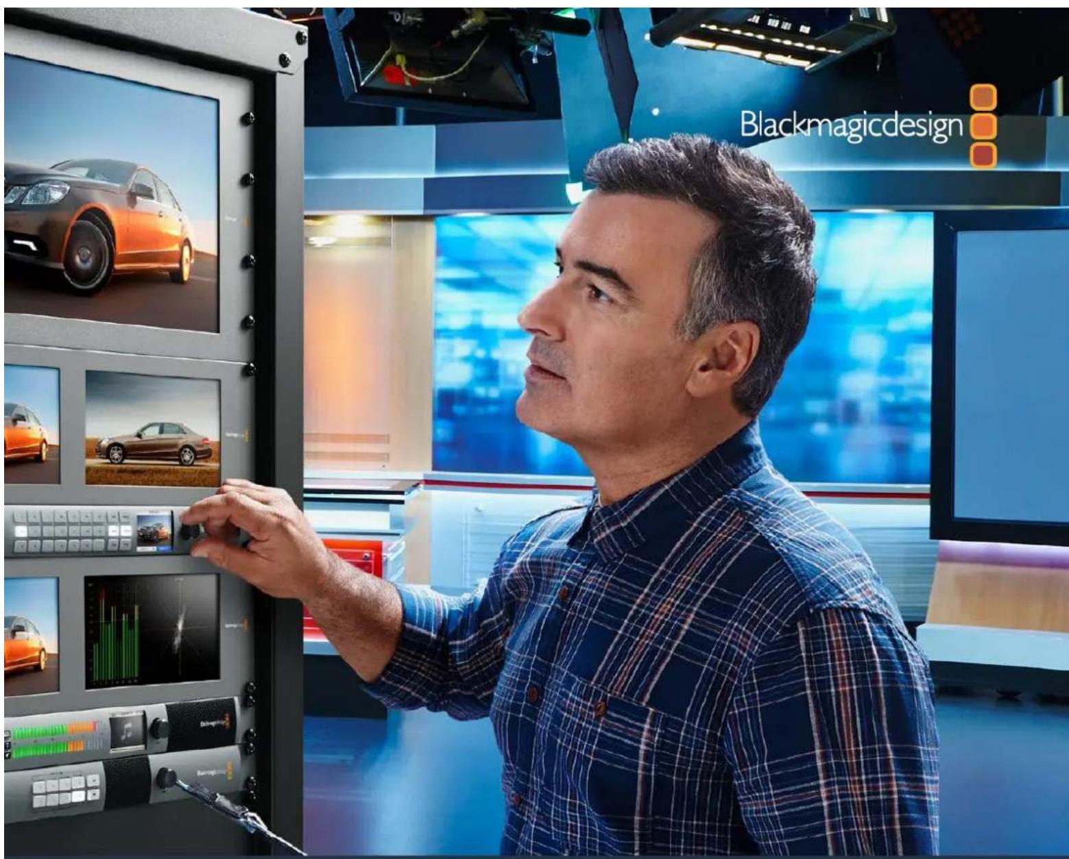
インストール/オペレーションマニュアル
Videohub
2020年1月
日本語

natural_image
Circular portrait photo of a smiling man in a dark shirt against a gray background (no text or symbols)ようこそ
Blackmagic Design CEO
グラント・ペティ
目次
Videohub
はじめに 97
Videohubを使用する前に 97
ビデオの接続 97
Videohubのコントロール 97
GPI and Tally Interface 106
USB接続でコントロールパネルを
コンフィギュレーション 106
イーサ ネットネットワークに 接 続
コントロールパネルのボタン診断 108
Videohubコントローラーの
ソフトウェア アップ デート 109
ルーティングレベル
ソース/送信先の選択方法 110
Videohub Smart Control Proを

natural_image
Front panel of an electronic device showing ports and connectors (no visible text or symbols)Videohub Master Control Pro
Videohub Smart Control Pro
natural_image
Front panel of a dual-chamber electronic device with square slots and mounting holes (no text or symbols visible)
natural_image
Front panel of an electronic device showing ports and connectors (no text or symbols visible)Videohub Smart Control Pro
GPI and Tally Interface
GPI and Tally Interface
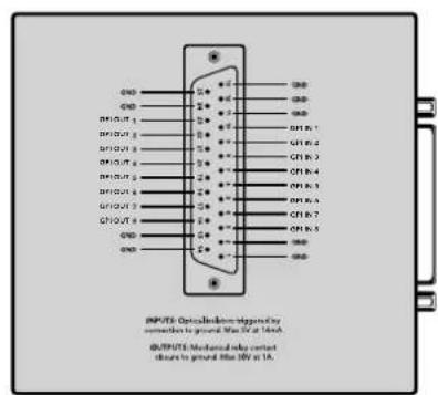
DB25コネクターのピン配列
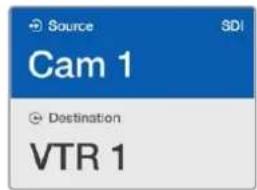
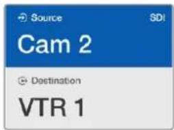
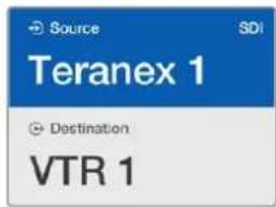
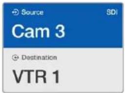
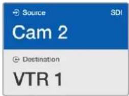
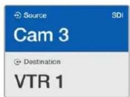
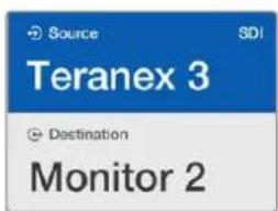
natural_image
Front panel of a dual-chamber electronic device with a red indicator light on the right side (no text or symbols visible)natural_image
Front panel of a dual-chamber electronic device showing white and yellow buttons with a red indicator at the bottom (no text or symbols)natural_image
Technical line drawing of a mechanical component with multiple cylindrical components and mounting holes (no text or symbols)natural_image
Illustration of a hand inserting into a patterned plastic block with a circular button (no text or symbols)natural_image
Illustration of a hand pressing down on a small object with an orange arrow (no text or symbols)natural_image
Illustration of a hand inserting into a mechanical component with circular components (no text or symbols)Universal Videohub 288
natural_image
Technical line drawing of a computer drive chassis with ventilation slots and ports (no text or symbols)natural_image
Technical line drawing of a multi-level storage unit with internal components and a highlighted section (no text or symbols)natural_image
Technical illustration of a cable connector assembly with two connectors and a panel, no text or symbols present.natural_image
Front panel of a rack-mounted server rack with multiple ports and connectors (no visible text or labels)使用を開始する前に
natural_image
Technical line drawing of a computer chassis with ports and connectors (no text or symbols)natural_image
Diagram of an industrial rack unit with a server rack and internal storage panel, showing no text or symbols.natural_image
Technical diagram of an electrical panel assembly with a highlighted component (no text or symbols present)Universal Videohub 72 Crosspoint
natural_image
3D diagram of an electronic device rear panel with multiple ports and connectors (no text or symbols visible)natural_image
Illustration of multiple connected VGA connectors (no text or symbols)Universal Videohub Deck Control Cable
3G-SDI Videohub Routers
natural_image
Front view of a server rack with multiple ports and connectors (no visible text or labels)Blackmagic Broadcast Videohub

natural_image
Front view of a rack-mounted electronic device with multiple ports and connectors (no visible text or labels)Blackmagic Studio Videohub

Blackmagic Compact Videohub
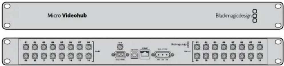
Blackmagic Micro Videohub
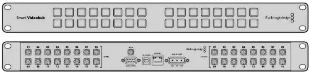
Blackmagic Smart Videohub

SRC/VIEW

SOLO/MENU
ラベルの保存とロード
Videohubの名前付け
IP Address: 192.168.24.103
Subnet Magic 255.255.255.0
Gateway: 192.168.10.1
Blackmagic Videohub Hardware Panel Setupのネットワーク設定
ラベルを編集したいボタンをクリック。
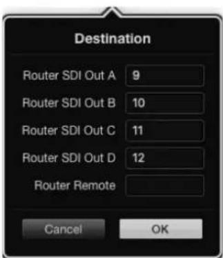
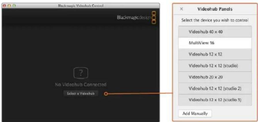
natural_image
Technical diagram of an internal server rack with connected modules and cable connections (no text or symbols)ヘルプライン
natural_image
Circular portrait photo of a smiling man in a dark shirt against a gray textured background (no text or symbols)Chère cliente, cher client,
GPI and Tally Interface 187
Videohub Master Control Pro
Videohub Smart Control Pro
natural_image
Front and back view of a dual-chamber network device with labeled ports (no text or symbols on the main body)Videohub Smart Control Pro
GPI and Tally Interface
GPI and Tally Interface
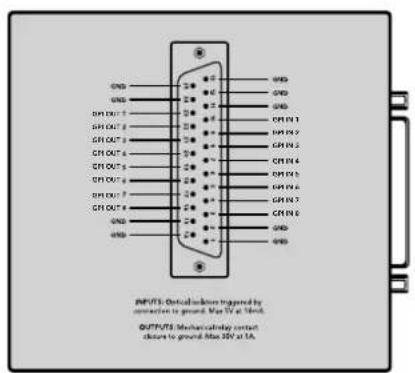
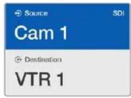
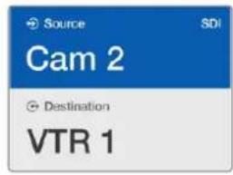
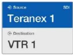
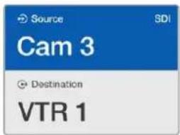
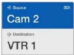
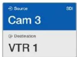
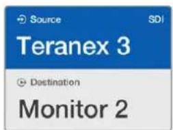
natural_image
Front panel of a dual-chamber electronic device with square slots and a highlighted red button (no text or symbols)natural_image
Front panel of a rack-mounted device showing rows of white and yellow buttons with one red button (no text or symbols)natural_image
Technical line drawing of a cabinet or rack with multiple circular components and mounting holes (no text or symbols)natural_image
Illustration of a hand inserting into a component with circular patterns, no text or symbols presentnatural_image
Illustration of a hand inserting a component into a mechanical housing (no text or symbols visible)Grilles de commutation Universal Videohub
Universal Videohub 288
Pour bien démarrer
Universal Videohub 288
natural_image
Technical line drawing of a computer drive chassis with cooling fins and ports (no text or symbols)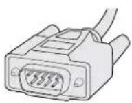
natural_image
3D diagram of a multi-level storage unit with internal structure and storage compartments (no text or symbols)natural_image
Technical diagram of a cable connector assembly with connectors and wiring (no text or symbols)natural_image
Front view of a rack-mounted industrial control unit with multiple ports and connectors (no visible text or labels)Pour bien démarrer
natural_image
Front view diagram of a computer chassis showing ports and connectors (no text or labels)natural_image
Diagram of an internal rack-mounted server unit with a highlighted internal panel and orange arrow indicating direction (no text or symbols present)natural_image
Technical diagram of an electrical panel assembly with a highlighted component (no text or symbols present)natural_image
3D diagram of a network device rear panel with multiple ports and connectors (no text or symbols visible)natural_image
Illustration of multiple connected VGA connectors (no text or symbols)natural_image
Front view of a rack-mounted server rack with multiple ports and connectors (no visible text or labels)Blackmagic Studio Videohub

Blackmagic Compact Videohub
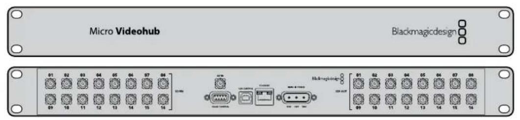
Blackmagic Micro Videohub
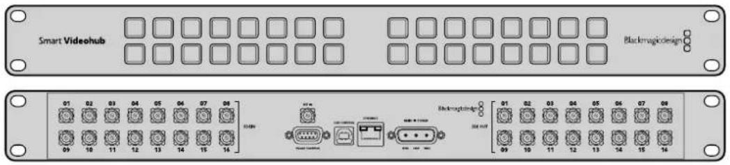
Blackmagic Smart Videohub

natural_image
Front panel of a network device showing multiple Ethernet ports and connectors (no visible text or labels)
SRC et VIEW
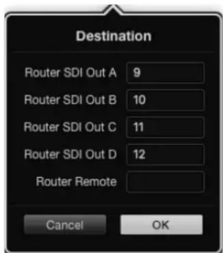
Momentary Hold Video
natural_image
Technical diagram of an internal server rack with connected modules and fan structures, showing internal wiring and mounting points (no text or symbols present)natural_image
Technical illustration of an electronic component assembly with a warning sign and warning triangle (no text or symbols present)Obtenir de l'aide
natural_image
Circular portrait photo of a smiling man in a dark shirt against a gray background (no text or symbols)Willkommen
CEO, Blackmagic Design
Inhaltsverzeichnis
Videohub
GPI and Tally Interface 268 Videohub Hardware Panel Setup 317
natural_image
Front and back view of a network device chassis showing two rectangular panels with labeled ports (no text or symbols on the panels themselves)Videohub Smart Control Pro
GPI and Tally Interface
GPI and Tally Interface
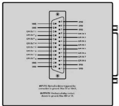
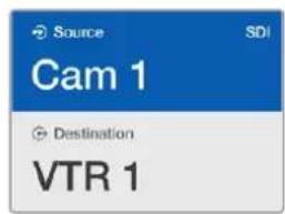
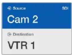
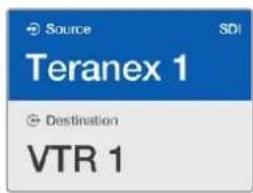
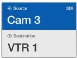
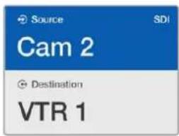
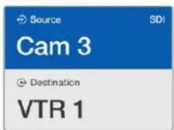
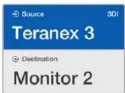
natural_image
Pure electrical circuit lines without any symbolsnatural_image
Front panel of a rack-mounted device showing a grid of white circular units and a row of yellow and red square units (no text or symbols)natural_image
Technical line drawing of a mechanical component with multiple cylindrical components and mounting holes (no text or symbols)natural_image
Illustration of a hand inserting into a plastic component with circular patterns (no text or symbols)natural_image
Illustration of a hand inserting into a mechanical component with circular components (no text or symbols)Universal Videohub 288
natural_image
Technical line drawing of a computer drive chassis with ventilation slots and ports (no text or symbols)
natural_image
3D rendering of a Unit 54 Visionshub Power Supply electronic device with connectors and ports (no text or symbols on the component itself)natural_image
3D architectural diagram of a multi-level storage unit with shelves and a central vertical structure, showing no text or symbols.natural_image
Technical diagram of a cable connector assembly with two connectors and a housing (no text or symbols visible)natural_image
Front panel of a rack-mounted server rack with multiple ports and connectors (no visible text or labels)natural_image
Diagram of an internal rack unit with a highlighted orange arrow indicating a directional movement or operation (no text or symbols present)natural_image
Technical diagram of an electrical panel assembly with a highlighted component (no text or symbols present)natural_image
3D diagram of a device rear panel with multiple ports and connectors (no text or symbols visible)natural_image
Illustration of multiple connected VGA connectors (no text or symbols)Universal Videohub Deck Control Cable
natural_image
Front view of a rack-mounted server rack with multiple ports and connectors (no visible text or labels)Blackmagic Broadcast Videohub

Blackmagic Studio Videohub

Blackmagic Compact Videohub
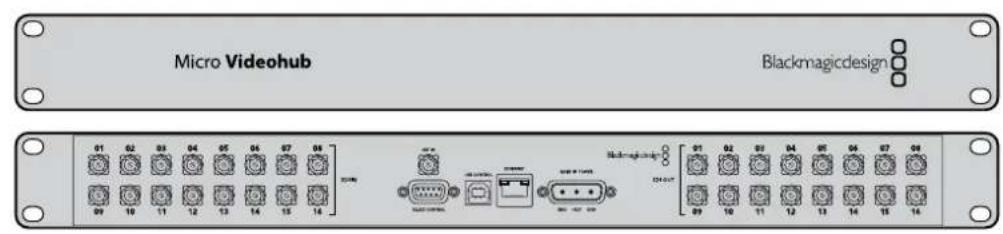
Blackmagic Micro Videohub
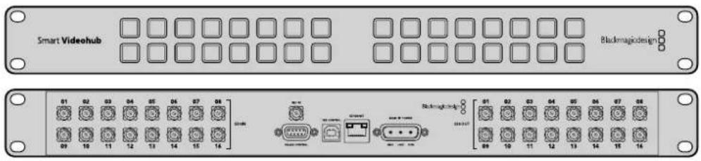
Blackmagic Studio Videohub

natural_image
Front panel of a network device showing multiple Ethernet ports and connectors (no visible text or labels)
SRC und VIEW

SOLO und MENU
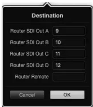
Momentary Hold Video

natural_image
Front panel of a network equipment rack with ports, connectors, and indicator lights (no readable text or symbols)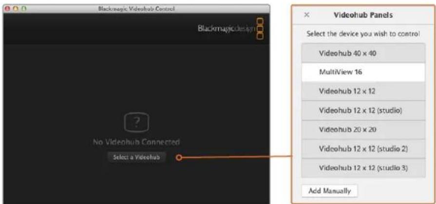
natural_image
Technical diagram of an internal server rack with heat exchangers and ventilation fans, showing internal components and connection points (no text or labels)Blackmagic Design Online-Support
California Proposition 65
natural_image
Circular portrait photo of a smiling man in a black shirt against a gray background (no text or symbols)Bienvenido
natural_image
Front and back view of a server rack unit with indicator lights and ports (no text or symbols visible)Videohub Smart Control Pro
Dispositivo GPI and Tally Interface
Dispositivo GPI and Tally Interface
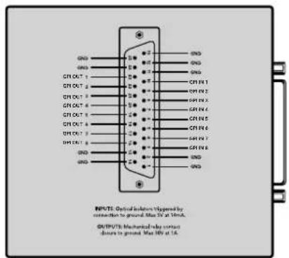
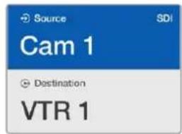
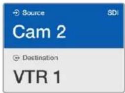
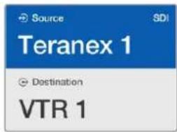
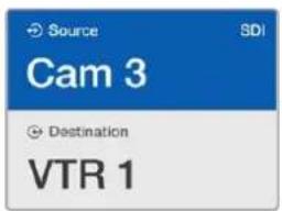
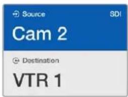
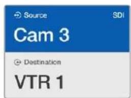
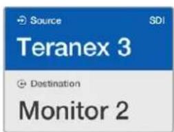
natural_image
Front panel of a dual-chamber electronic device with grid and indicator lights (no text or symbols)natural_image
Diagram of a control panel with yellow and red squares arranged in rows, no text or symbols presentnatural_image
Technical line drawing of a mechanical component with multiple circular components and mounting holes (no text or symbols)natural_image
Illustration of a hand inserting into a mechanical component with circular patterns (no text or symbols)natural_image
Illustration of a hand inserting a component into a mechanical part (no text or symbols visible)Universal Videohub 288
natural_image
3D technical illustration of a computer drive chassis with cooling fins and ports (no text or symbols)
Universal Videohub 288 Crosspoint Cable serial
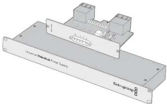
natural_image
Technical line drawing of a multi-level storage unit with internal components and a highlighted section (no text or symbols)natural_image
Technical diagram of an electrical panel assembly with a highlighted component (no text or symbols present)natural_image
Diagram of an electrical connector assembly showing cable routing and internal components (no text or symbols)natural_image
Technical illustration of a cable connector assembly with mounting brackets and wiring (no text or symbols)natural_image
Front panel of a rack-mounted server rack with multiple ports and connectors (no visible text or labels)Primeros pasos
natural_image
Technical line drawing of a computer chassis with ports and connectors (no text or symbols)natural_image
Diagram of an internal rack-mounted server unit with a highlighted orange arrow indicating a component (no text or symbols present)natural_image
Technical diagram of an electrical panel assembly with a highlighted component (no text or symbols present)natural_image
Illustration of a network device with multiple ports and connectors (no text or symbols visible)natural_image
Illustration of four connected VGA connectors (no text or symbols)Cable Universal Videohub Deck Control
Matrices Videohub SDI 3G
natural_image
Front view of a rack-mounted server rack with multiple ports and connectors (no visible text or labels)Blackmagic Broadcast Videohub

natural_image
Front view of a rack-mounted electronic device with multiple ports and connectors (no visible text or labels)Blackmagic Studio Videohub

Blackmagic Compact Videohub
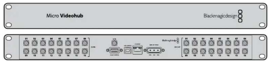
Blackmagic Micro Videohub
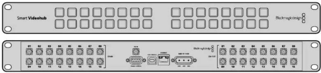
Blackmagic Smart Videohub

natural_image
Front panel of a network equipment rack with ports, connectors, and ventilation slots (no visible text or labels)
SRC y VIEW
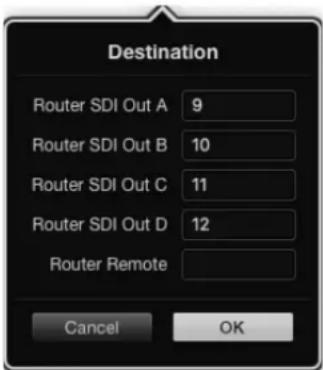
natural_image
Technical illustration of a mechanical assembly with a warning sign and warning triangle (no text or symbols present)Cómo obtener ayuda
- SDI 3G: PL-4F20-311C

安装操作手册
Videohub
2020年1月
中文

natural_image
Circular portrait photo of a smiling man in a dark shirt against a gray textured background (no text or symbols)欢迎辞
感谢您购买Videohub产品!
GPI and Tally Interface 430
连接USB配置控制面板 430
连接以太网网络 431
控制面板按钮诊断 432
natural_image
Front and back view of a server rack unit with front panel, internal connectors, and terminal ports (no text or symbols visible)Videohub Smart Control Pro
GPI and Tally Interface
GPI and Tally Interface
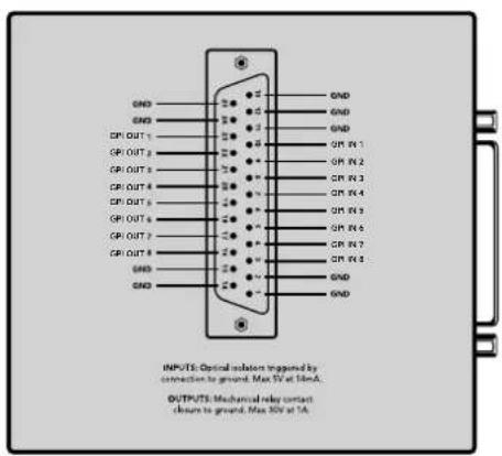
DB25接口引脚图
如需升级软件时则会弹出该对话框。
关于指派级别
前面板显示了所选的新源。
如何选择源信号和目标信号
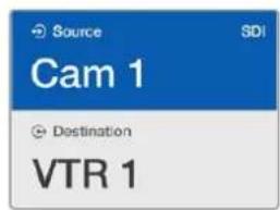
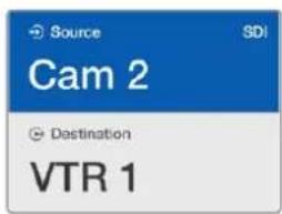
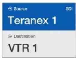
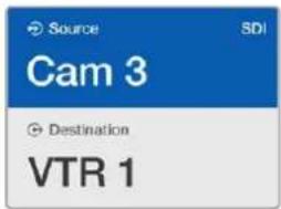
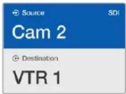
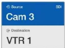
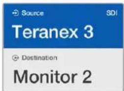
目标锁定后,目标栏将出现锁定图标。
通过Videohub Master Control解锁目标:
natural_image
Front panel of a dual-chamber electronic device with grid and indicator lights (no readable text or symbols)natural_image
Front panel of a rack-mounted device showing a grid of square units with yellow and red indicators, no visible text or symbols.natural_image
Technical line drawing of a cabinet or rack with multiple circular components and a labeled component (no text or symbols present)natural_image
Close-up of a hand inserting a component into a mechanical part, showing circular patterns and a small circular mark (no text or symbols)natural_image
Close-up of hands operating a mechanical component with circular components and a circular knob (no text or symbols visible)Universal Videohub矩阵
Universal Videohub 288
初次使用前的准备工作
Universal Videohub 288
Universal Videohub 288交叉点插卡
natural_image
3D technical illustration of a computer drive chassis with cooling fins and ventilation slots (no text or symbols)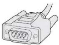
串行电缆
Universal Videohub 288交叉点插卡
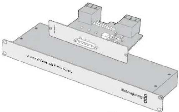
natural_image
Technical line drawing of a multi-level storage unit with internal components and a highlighted section (no text or symbols)natural_image
Technical diagram of an electrical panel assembly with a highlighted component (no text or symbols present)natural_image
Technical diagram of an electrical connector assembly with orange arrows indicating connection points (no text or symbols present)natural_image
Technical diagram of a cable connector assembly with connectors and wiring (no text or symbols)Universal Videohub 288可安装两套Universal Videohub Power Supply作为冗余电源。
Universal Videohub 72
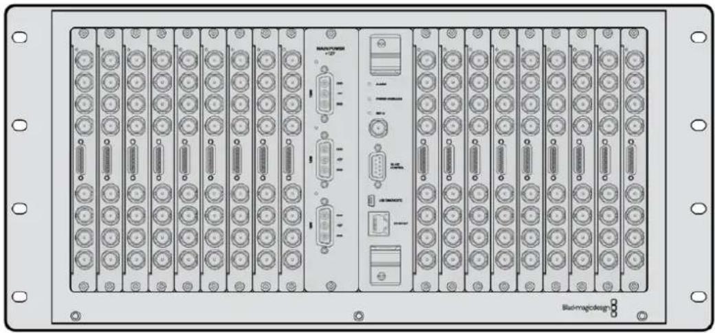
natural_image
Front panel of a network equipment rack with multiple ports and connectors (no visible text or labels)初次使用前的准备工作
natural_image
Front view of a computer chassis showing front panel, ports, and connectors (no text or symbols visible)natural_image
Diagram of an internal server rack with a highlighted orange arrow indicating a component or operation (no text or symbols present)natural_image
Technical diagram of an electrical panel assembly with a highlighted component (no text or symbols present)安装Universal Videohub SDI Interface接口插卡
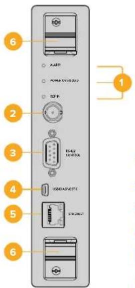
Universal Videohub 72 Crosspoint
Universal Videohub LED状态灯
natural_image
3D diagram of a computer interface unit with ports and connectors (no text or symbols visible)natural_image
Illustration of four connected VGA connectors (no text or symbols)Universal Videohub Deck Control Cable
3G-SDI Videohub矩阵
Blackmagic 3G-SDI Videohub矩阵
natural_image
Front view of a rack-mounted electronic device with multiple ports and connectors (no visible text or labels)Blackmagic Broadcast Videohub

Blackmagic Studio Videohub

Blackmagic Compact Videohub
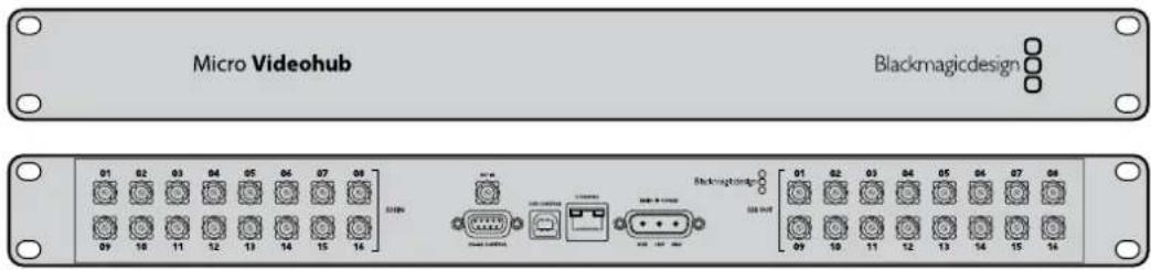
Blackmagic Micro Videohub
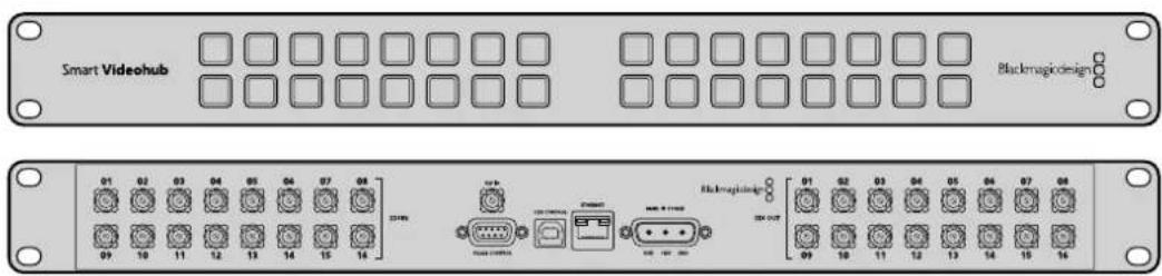
Blackmagic Smart Videohub

natural_image
Front panel of a network equipment rack with multiple ports and connectors (no visible text or labels)
SRC和VIEW
保存和加载多个标签
为Videohub命名
请勿在更新过程中断开Videohub。
Blackmagic Videohub Control
IP Address: 192.168.24.103
Subnet Mask: 255.255.255.0
Gateway: 192.168.10.1
点击相应按钮来编辑它的标签。
配置Videohub Smart Control Pro
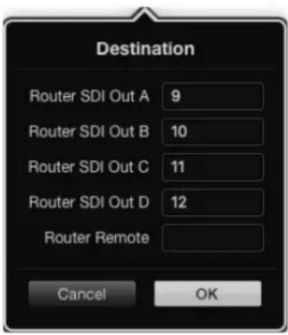
设置GPI and Tally Interface
配置GPI and Tally Interface
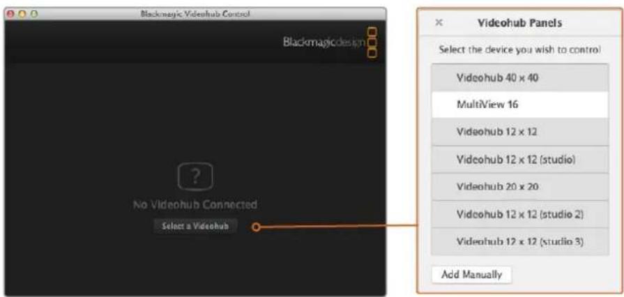
natural_image
Technical diagram of an internal server rack with fan and ventilation system, showing internal components and wiring (no text or labels)更换Broadcast Videohub的风扇
natural_image
Technical illustration of an electrical component assembly with a warning symbol (no text or labels present)获得帮助
설치 및 사용 설명서
Videohub
2020년 1월
한국어

natural_image
Circular portrait photo of a smiling man in a dark shirt against a gray background (no text or symbols)환영합니다
GPI and Tally Interface 511
natural_image
Front panel of a dual-chamber electronic device with grid layout and mounting holes (no text or symbols)
natural_image
Front panel of a network device showing three connected ports (no visible text or labels)Videohub Smart Control Pro
GPI and Tally Interface
GPI and Tally Interface
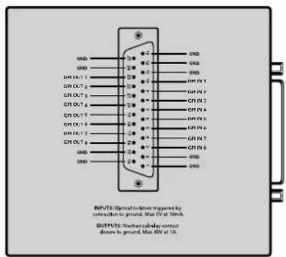
DB25 커넥터의 핀 배치도
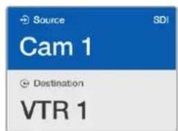
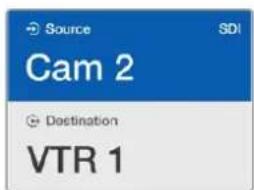
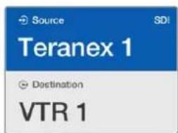
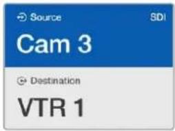
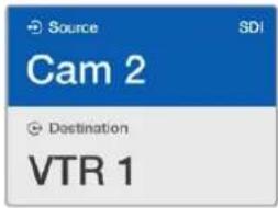
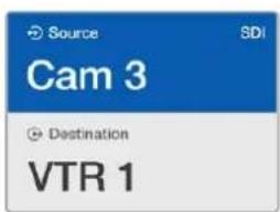
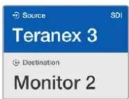
natural_image
Front panel of a dual-chamber electronic device with grid and indicator lights (no readable text or symbols)natural_image
Diagram of a 24-pin connector with yellow and red indicators, no text or symbols presentnatural_image
Technical line drawing of a mechanical component with multiple circular components and mounting holes (no text or symbols)natural_image
Illustration of a hand inserting into a plastic component with circular patterns (no text or symbols)natural_image
Illustration of hands operating a mechanical component with a circular button (no text or symbols)Universal Videohub 288
natural_image
Technical line drawing of a rectangular electronic device with heat sinks and ports (no text or symbols)natural_image
3D architectural diagram of a multi-level storage unit with internal structure and storage compartments (no text or symbols)natural_image
Technical diagram of a cable connector inserted into an electrical enclosure (no text or symbols visible)natural_image
Front panel of a rack-mounted industrial control unit with multiple drive bays and labeled ports (no readable text or symbols beyond labels)시작하기
natural_image
Technical line drawing of a computer chassis rear panel with ports and connectors (no text or symbols)natural_image
Diagram of an internal rack-mounted server unit with a highlighted orange arrow indicating a component (no text or symbols present)natural_image
Technical diagram of an electrical panel assembly with a highlighted component (no text or symbols present)Universal Videohub SDI 설치하기
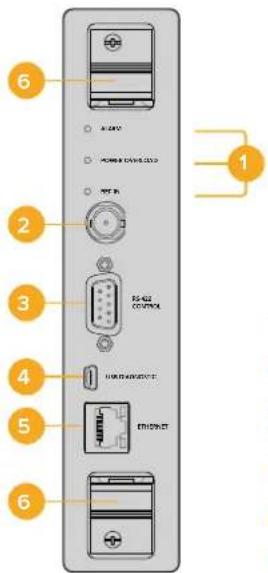
natural_image
Diagram of a network device rear panel with multiple ports and connectors (no text or labels visible)natural_image
Illustration of multiple connected VGA connectors (no text or symbols)Universal Videohub Deck Control 케이블
3G-SDI Videohub 라우터
natural_image
Front view of a server rack with multiple ports and connectors (no visible text or labels)Blackmagic Broadcast Videohub

Blackmagic Studio Videohub

Blackmagic Compact Videohub
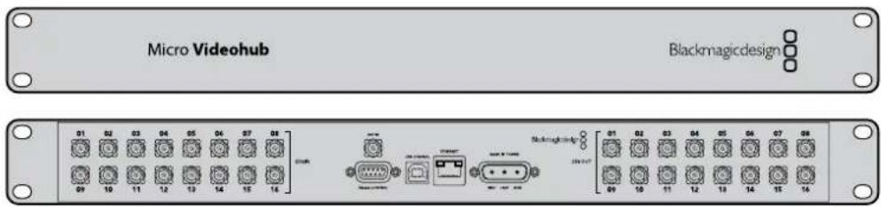
Blackmagic Micro Videohub
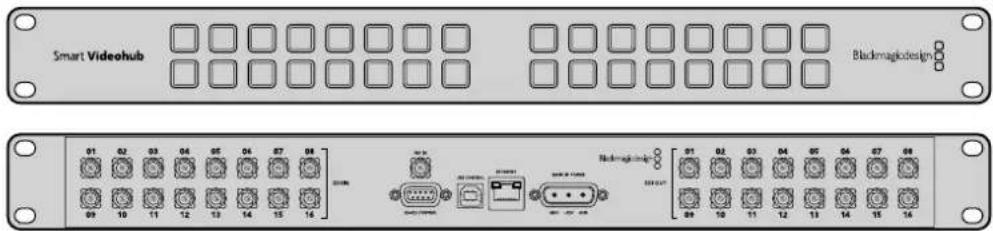
Blackmagic Smart Videohub

natural_image
Front panel of a network device showing multiple Ethernet ports and connectors (no visible text or labels)
SRC 및 VIEW
라벨 저장 및 불러오기
Videohub 기기명 설정하기
IP Address: 192.168.24.103
Subnet Mask: 255.255.255.0
Gateway: 192.168.10.1
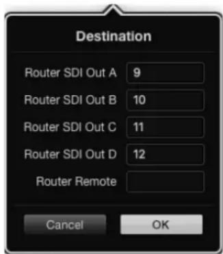

natural_image
Front panel of a network equipment rack with ports, connectors, and indicator lights (no visible text or symbols)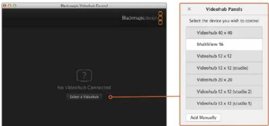
natural_image
Technical illustration of an electronic component assembly with a warning sign and warning triangle (no text or symbols present)지원 받기
natural_image
Circular portrait photo of a smiling man in a dark shirt against a gray textured background (no text or symbols)GPI and Tally Interface 592
natural_image
Front and back view of a rack-mounted server or network device with multiple ports and connectors (no visible text or symbols)Videohub Smart Control Pro
GPI and Tally Interface
GPI and Tally Interface
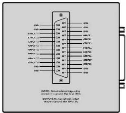
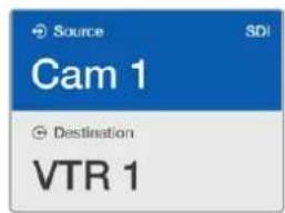
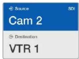
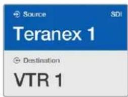
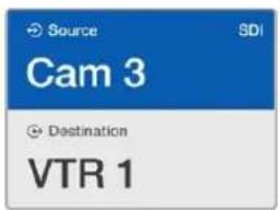
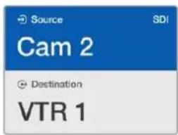
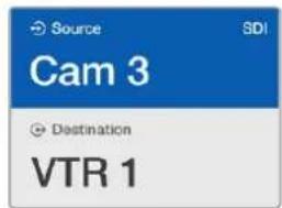
natural_image
Front panel of a server rack with grid layout and a highlighted red button (no text or symbols)natural_image
Diagram of a server rack with grid layout and highlighted yellow and red squares (no text or symbols)natural_image
Technical line drawing of a mechanical component with circular components and a 3kg dimension label (no text or symbols beyond basic geometry)natural_image
Illustration of a hand inserting into a mechanical component with circular patterns (no text or symbols)natural_image
Illustration of a hand pressing down on a small object with an orange arrow (no text or symbols)natural_image
Illustration of a hand using a tool to adjust or install a mechanical component (no text or symbols visible)Universal Videohub 288
natural_image
Technical line drawing of a rectangular electronic device with ventilation grilles and ports (no text or symbols)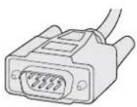
natural_image
Technical diagram of a multi-level storage unit with internal structure and storage racks (no text or symbols)natural_image
Technical diagram of an electrical panel assembly with a highlighted component (no text or symbols present)Установка платы Universal Videohub SDI Interface
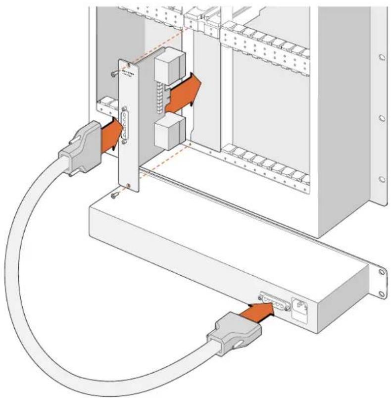
natural_image
Technical diagram of an electrical connector assembly with orange arrows indicating connection points (no text or symbols present)natural_image
Technical diagram of a cable connector assembly with connectors and wiring (no text or symbols)natural_image
Front panel of a rack-mounted server rack with multiple ports and connectors (no visible text or labels)natural_image
Technical line drawing of a computer chassis with ports and connectors (no text or symbols)natural_image
Diagram of an internal rack-mounted server unit with a highlighted orange arrow indicating a component (no text or symbols present)natural_image
Technical diagram of an electrical panel assembly with a highlighted component (no text or symbols present)natural_image
3D diagram of a network switch device with multiple ports and connectors (no text or labels visible)natural_image
Illustration of four connected VGA connectors (no text or symbols)Universal Videohub Deck Control Cable
Blackmagic Broadcast Videohub

Blackmagic Studio Videohub

natural_image
Front panel of a network equipment chassis showing multiple Ethernet ports and connectors (no visible text or labels)Blackmagic Compact Videohub
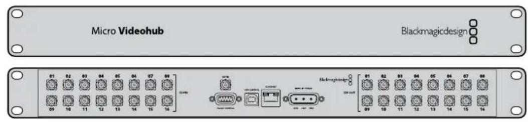
Blackmagic Micro Videohub
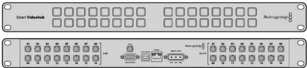
Blackmagic Smart Videohub

natural_image
Front panel of a network equipment rack with ports, connectors, and indicator lights (no readable text or symbols)
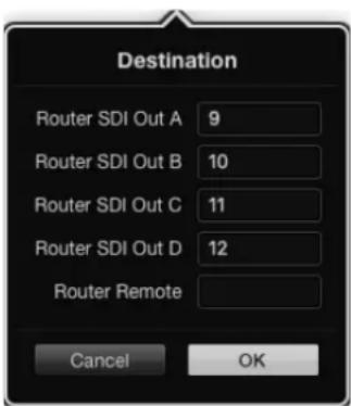
natural_image
Technical illustration of an internal server rack with connected modules and fan structures (no text or symbols)Замена вентилятора на Broadcast Videohub
natural_image
Technical illustration of a mechanical assembly with a warning sign and warning triangle (no text or symbols present)Как получить помощь
natural_image
Circular portrait photo of a smiling man in a dark shirt against a gray textured background (no text or symbols)Gentile utente
AD Blackmagic Design
Indice
Videohub
GPI and Tally Interface 673
natural_image
Front and back view of a rack-mounted server or network device with indicator lights and ports (no text or symbols visible)Videohub Smart Control Pro
GPI and Tally Interface
GPI and Tally Interface
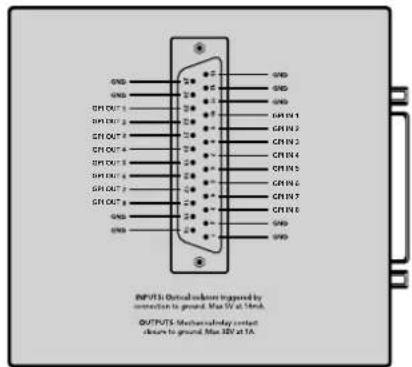
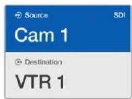
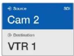
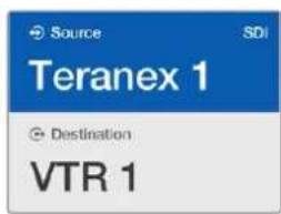
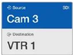
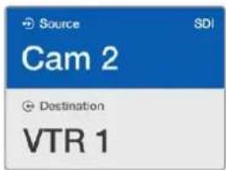
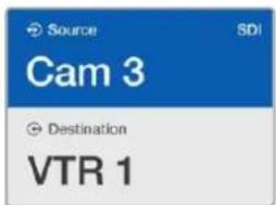
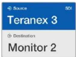
natural_image
Pure electrical circuit lines without any symbolsnatural_image
Front panel of a rack-mounted electronic device showing a grid of white and yellow squares with one red square highlighted (no text or symbols)natural_image
Technical line drawing of a mechanical component with circular components and mounting holes (no text or symbols)Colloca Videohub su una superficie stabile.
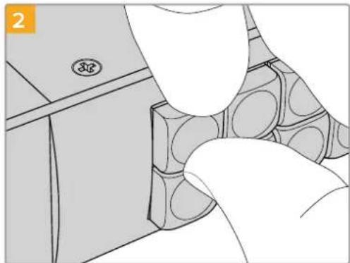
natural_image
Illustration of a hand inserting into a container with circular patterns (no text or symbols)natural_image
Illustration of a hand pressing a button with an orange arrow (no text or symbols)natural_image
Illustration of a hand using a tool to adjust or install a mechanical component (no text or symbols visible)Universal Videohub 288
Scheda crosspoint
natural_image
Technical line drawing of a rectangular electronic device with heat sinks and ports (no text or symbols)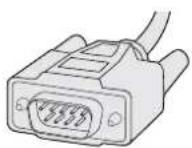
Scheda crosspoint per Universal Videohub 288 Cavo seriale
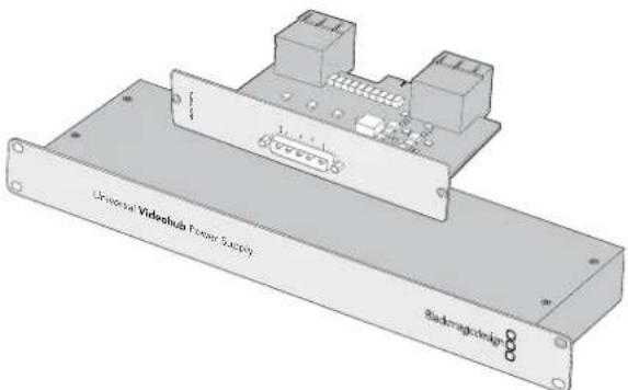
natural_image
3D architectural diagram of a multi-level storage unit with shelves and a central panel, showing structural components and a directional arrow (no text or symbols)natural_image
Technical diagram of an electrical panel assembly with a highlighted component (no text or symbols present)natural_image
Technical diagram of an electrical connector assembly with orange arrows indicating connection points (no text or symbols present)natural_image
Technical illustration of a cable connector assembly with mounting brackets and wiring (no text or symbols)natural_image
Front panel of a rack-mounted server rack with multiple ports and connectors (no visible text or labels)Introduzione
natural_image
Technical line drawing of a computer chassis with ports and connectors (no text or symbols)natural_image
Diagram of an internal rack-mounted server unit with a highlighted internal panel and directional arrow (no text or symbols)natural_image
Technical diagram of an electrical panel assembly with a highlighted component (no text or symbols present)natural_image
Diagram of an Ethernet RJ4783 network device showing ports and connectors (no text or labels)natural_image
Illustration of four connected VGA connectors (no text or symbols)Universal Videohub Deck Control Cable
Matrici Videohub 3G-SDI
Modelli
natural_image
Front view of a rack-mounted electronic device with multiple ports and connectors (no visible text or labels)Blackmagic Broadcast Videohub

Blackmagic Studio Videohub

Blackmagic Compact Videohub
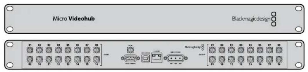
Blackmagic Micro Videohub
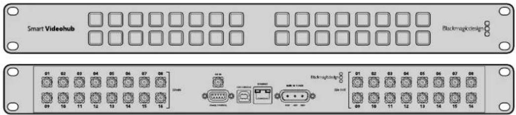
Blackmagic Smart Videohub

natural_image
Front panel of a network device showing multiple Ethernet ports and connectors (no readable text or symbols)
SRC e VIEW
SOLO
SET
MENU
1
SRC
SET
SOLO
The Ground Truth image displays a single, solid horizontal line. According to Rule 2 (UNDERSCORE & LINE RULES), this is a stylistic or background line, not a placeholder underscore. Therefore, the OCR result must ignore it and output nothing or only meaningful text. The provided OCR content is "____", which consists of four underscores. This is an incorrect interpretation of the line as a placeholder, violating the rule that stylistic lines must be ignored. The OCR has hallucinated underscores where none should exist based on the GT's visual context. Hence, the OCR result is inconsistent with the Ground Truth.
m = 311
SOLO
SET
MENU
1
SRC
VIEW
SET
SOLO
MENU
SOLO
SET
MENU
1
SRC
VIEW
SET
SOLO
MENU
SOLO
SET
MENU
1
SRC
VIEW
SET
SOLO
MENU
SOLO
SET
MENU
1
SRC
VIEW
SET
SOLO
MENU
SOLO
SET
MENU
1
SRC
VIEW
SET
SOLO
MENU
SOLO
SET
MENU
1
SRC
VIEW
SET
SOLO
MENU
SOLO
SET
MENU
1
SRC
VIEW
SET
SOLO
MENU
SOLO
SET
MENU
1
SRC
VIEW
SET
SOLO
MENU
SOLO
SET
MENU
1
SRC
VIEW
SET
SOLO
MENU
II software Blackmagic Videohub
Installazione
Momentary Hold Video
Configurare GPI and Tally Interface
GPI and Tally Interface collegato tramite USB

natural_image
Front panel of a network equipment rack with ports, connectors, and indicator lights (no readable text or symbols)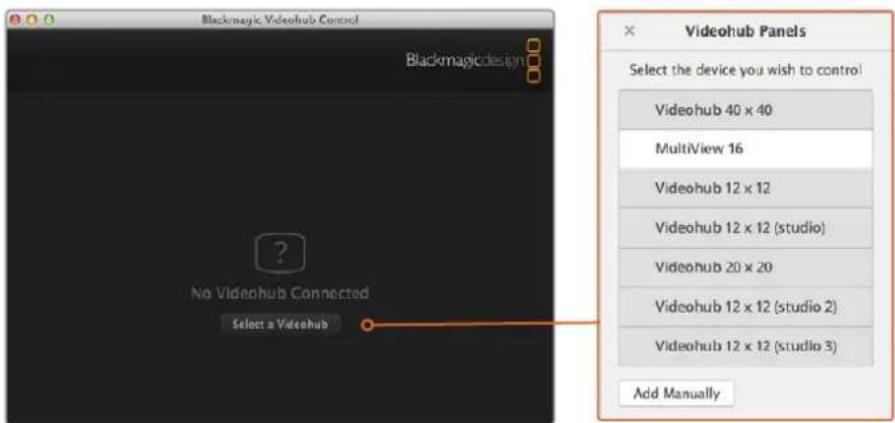
natural_image
Technical illustration of an electronic component assembly with a warning symbol (no text or labels present)Assistenza tecnica
natural_image
Circular portrait photo of a smiling man in a dark shirt against a textured gray background (no text or symbols)Bem-vindo
GPI and Tally Interface 754
Videohub Master Control Pro.
Videohub Smart Control Pro
natural_image
Front and back view of a server rack unit with labeled ports (no text or symbols on the main body)Videohub Smart Control Pro.
GPI and Tally Interface
GPI and Tally Interface.
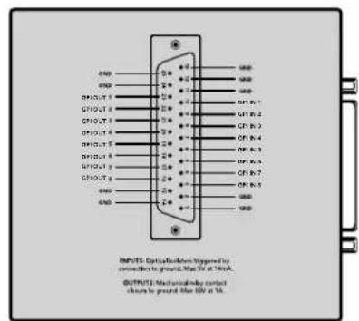
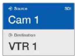
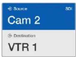
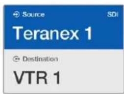
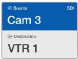
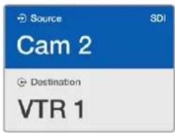
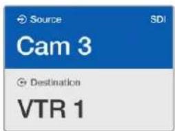
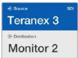
O campo de destino exibe um ícone de cadeado se o destino estiver bloqueado.
natural_image
Pure electrical circuit lines without any symbolsnatural_image
Diagram of a rack-mounted device with yellow and red indicator lights, no text or symbols presentnatural_image
Technical line drawing of a mechanical component with multiple cylindrical components and mounting holes (no text or symbols)natural_image
Illustration of a hand inserting into a plastic component with circular patterns (no text or symbols)natural_image
Illustration of a hand inserting into a mechanical component with a circular button (no text or symbols)Universal Videohub 288.
Universal Videohub 288 Crosspoint Card
natural_image
Technical illustration of a computer drive chassis with ventilation slots and ports (no text or symbols)
Placa de Ponto de Cruzamento Universal Videohub 288. Cabo Serial.
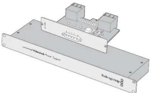
natural_image
3D rendering of a Unitari Videdink Power Supply and Microgate device (no text or symbols on the components)natural_image
Technical line drawing of a multi-level storage unit with internal components and a highlighted section (no text or symbols)natural_image
Technical diagram of a server rack with an orange arrow indicating a component inserted into the rack (no text or symbols present)natural_image
Technical diagram of an electrical connector assembly with orange arrows indicating connection points (no text or symbols present)The Universal Videohub Power Supply consists of a power card which is inserted into the Universal Videohub 288 and then connected to a 1 RU chassis located under the Universal Videohub 288.
natural_image
Technical illustration of a cable connector assembly with connectors and wiring (no text or symbols)natural_image
Front panel of a rack-mounted server rack with multiple ports and connectors (no visible text or labels)natural_image
Technical line drawing of a computer chassis with ports and connectors (no text or symbols)natural_image
Technical diagram of an industrial rack unit with a heat exchanger and internal components (no text or symbols)natural_image
Technical diagram of an electrical panel assembly with a highlighted component (no text or symbols visible)natural_image
3D diagram of a device rear panel with multiple ports and connectors (no text or symbols visible)natural_image
Illustration of four connected VGA connectors (no text or symbols)Universal Videohub Deck Control Cable.
Roteadores Videohub3G-SDI
Roteadores Blackmagic Videohub 3G-SDI
Blackmagic Broadcast Videohub.

Blackmagic Studio Videohub.

Blackmagic Compact Videohub.
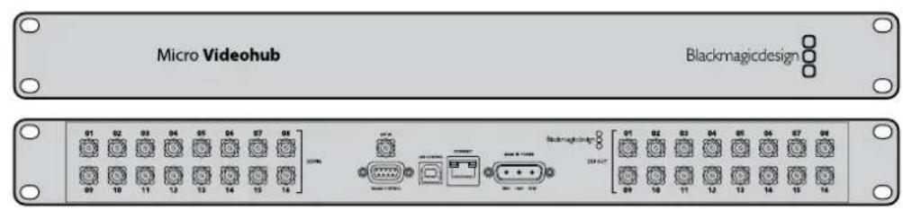
Blackmagic Micro Videohub.
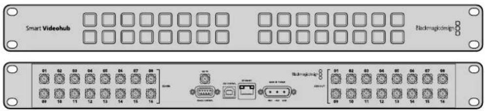
Blackmagic Smart Videohub.
Usando o Smart Videohub Control Panel

natural_image
Front view of a network switch or rack with multiple ports and connectors (no visible text or labels)
SRC e VIEW
IP Address: 192.168.24.103
Subnet Mask: 255.255.255.0
Gateway: 192.168.10.1
Number of Destinations
Videohub Smart Control Pro configurado com múltiplos destinos.
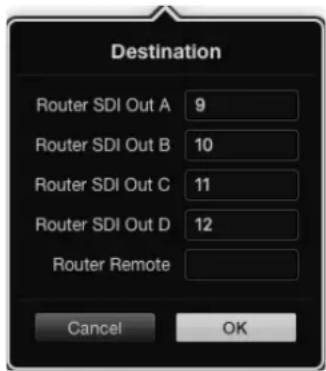
Adicione um número de porta a todos os campos SDI ao utilizar destinos SDI de enlace quádruplo.
Momentary Hold Video
Configurando a GPI and Tally Interface
Configurando a GPI and Tally Interface
3 Abra o Videohub Hardware Panel Setup.
GPI and Tally Interface conectada via USB.

natural_image
Front panel of a network equipment rack with multiple ports and connectors (no visible text or labels)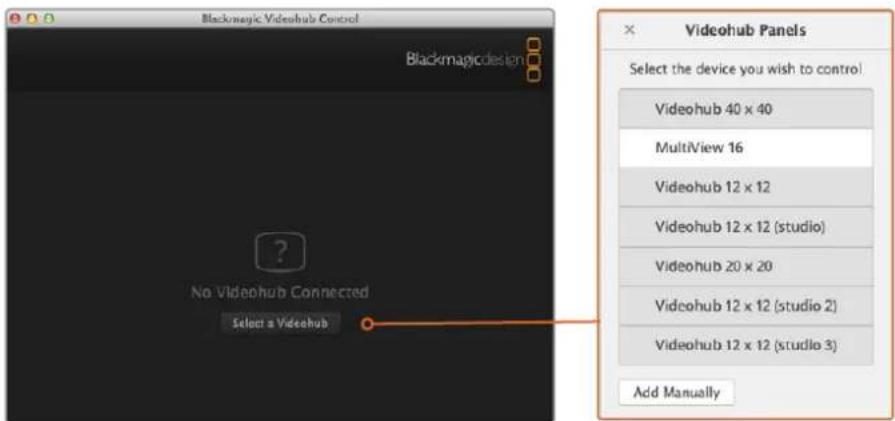
natural_image
Technical illustration of an electronic component assembly with a warning sign and warning symbol (no text or labels present)Obter Ajuda
natural_image
Circular portrait photo of a smiling man in a dark shirt against a gray background (no text or symbols)Hoş Geldiniz
Blackmagic Design CEO
İçindekiler
Videohub
Başlarken
natural_image
Front and back view of a server rack unit with indicator lights and ports (no text or symbols visible)Videohub Smart Control Pro
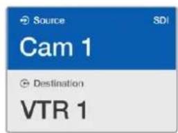
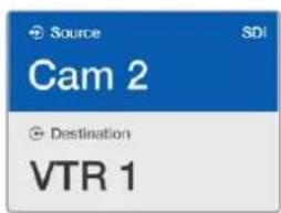
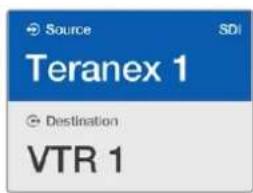
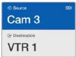
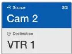
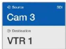
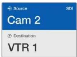
natural_image
Front panel of a computer RAM module showing 24 slots and one highlighted red button (no text or symbols)natural_image
Front panel of a dual-chamber electronic device showing white and yellow buttons with a red accent (no text or symbols)natural_image
Technical line drawing of a mechanical component with circular components and mounting holes (no text or symbols)natural_image
Illustration of a hand inserting into a plastic component with circular patterns (no text or symbols)natural_image
Illustration of a hand inserting a component into a mechanical housing (no text or symbols visible)Universal Videohub 288
Universal Videohub 288 Crosspoint Kartı
natural_image
3D technical illustration of a computer drive chassis with ports and ventilation slots (no text or symbols)
Universal Videohub 288 Crosspoint karti Seri Kablo
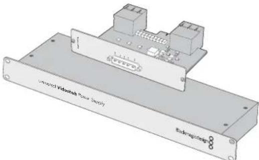
natural_image
3D schematic of a multi-level storage unit with internal components and a highlighted section (no text or symbols)natural_image
Technical diagram of an electrical panel assembly with a highlighted component (no text or symbols present)Bir Universal Videohub SDI Interface Card takılırken.
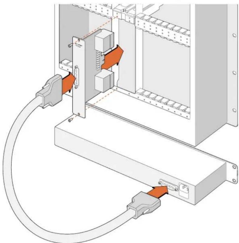
natural_image
Technical diagram of an electrical connector assembly with orange arrows indicating connection points (no text or symbols present)natural_image
Technical illustration of a cable connector assembly with connectors and wiring (no text or symbols)natural_image
Front panel of a rack-mounted server rack with multiple ports and connectors (no visible text or labels)natural_image
Technical line drawing of a computer chassis rear panel with ports and connectors (no text or symbols)natural_image
Two types of connected USB connectors shown in line drawings (no text or symbols)Seri Kablo Standard RJ45 Ethernet Kablosu
Güç Kaynağı
natural_image
Diagram of an internal rack-mounted server unit with a highlighted internal panel and directional arrow (no text or symbols)natural_image
Technical diagram of an electrical panel assembly with a highlighted component (no text or symbols present)natural_image
Diagram of a rack-mounted electronic device with multiple ports and connectors (no text or symbols visible)natural_image
Illustration of multiple connected V168 connectors (no text or symbols)Universal Videohub Deck Control Cable

natural_image
Front panel of a network device with ports, connectors, and ventilation slots (no readable text or symbols)
SRC
SOLO
SOLO ve MENU
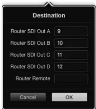
GPI and Tally Interface Kurulumu

natural_image
Front panel of a network equipment rack with multiple ports and connectors (no visible text or labels)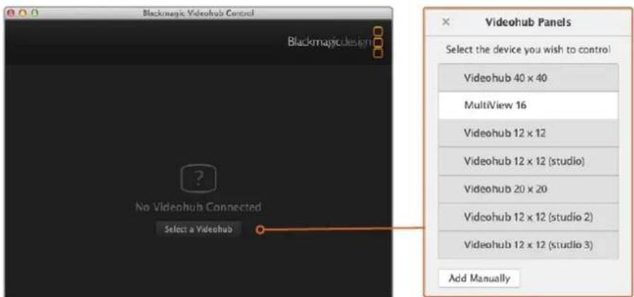
Yardım İçin
Developer Information
Videohub
January 2020
Developer Information
Blackmagic Videohub Ethernet Protocol v2.3
Summary
The Blackmagic Videohub Ethernet Protocol is a text based protocol that is accessed by connecting to TCP port 9990 on a Videohub Server. Integrated Videohub Servers and Videohub Server computers are supported by the protocol.
The Videohub Server sends information in blocks which each have an identifying header in all-caps, followed by a full-colon. A block spans multiple lines and is terminated by a blank line. Each line in the protocol is terminated by a newline character.
Upon connection, the Videohub Server sends a complete dump of the state of the device. After the initial status dump, status updates are sent every time the Videohub status changes.
To be resilient to future protocol changes, clients should ignore blocks they do not recognize, up to the trailing blank line. Within existing blocks, clients should ignore lines they do not recognize.
LEGEND
← line feed or carriage return
... and so on
Version 2.3 of the Blackmagic Videohub Ethernet Protocol was released with Videohub 4.9.1 software.
Protocol Preamble
The first block sent by the Videohub Server is always the protocol preamble:
PROTOCOL PREAMBLE: ←
Version: 2.3←
←
The version field indicates the protocol version. When the protocol is changed in a compatible way, the minor version number will be updated. If incompatible changes are made, the major version number will be updated.
Device Information
The next block contains general information about the connected Videohub device. If a device is connected, the Videohub Server will report the attributes of the Videohub:
VIDEOHUB DEVICE:←
Device present: true←
Model name: Blackmagic Smart Videohub←
Video inputs: 10←
Video processing units: 0←
Video outputs: 10←
Video monitoring outputs: 0←
Serial ports: 0←
This example is for the Smart Videohub which is a 16x16 router.
If the Videohub Server has no device connected, the block will simply be:
VIDEOHUB DEVICE:
Device present: false
←
If a device is present, but has an incompatible firmware, the status reported will be:
VIDEOHUB DEVICE:
Device present: needs _ update
←
In the last two situations, no further information will be sent, unless the situation is rectified.
If the Videohub Server detects a new Videohub attached, it will resend all blocks except the protocol preamble to indicate the device has changed, and allow the client to update its cache of server state.
Initial Status Dump
The next four blocks enumerate the labels assigned to the input, output, monitoring and serial ports.
Videohubs that do not have monitoring or serial ports do not send the corresponding blocks.
INPUT LABELS
0 VTR 1←
1 VTR 2
...
←
OUTPUT LABELS
0 Output feed 1←
1 Output feed 2
***
←
MONITORING OUTPUT LABELS:
0 Monitor feed 1←
1 Monitor feed 2
***
←
SERIAL PORT LABELS:
0 Deck 1
1 Deck 2
←
NOTE Ports are always numbered starting at zero in the protocol which matches port one on the chassis.
The next three blocks describe the routing of the output, monitoring and serial ports.
VIDEO OUTPUT ROUTING←
0 5←
1 3←
...
←
VIDEO MONITORING OUTPUT ROUTING:←
0 7←
1 8←
...
←
SERIAL PORT ROUTING:←
0 12←
1 11←
...
←
Videohubs with processing units (only the Workgroup Videohub) send an extra routing block:
PROCESSING UNIT ROUTING:
0 5
1 3
...
←
Videohubs with frame buffers (only the Workgroup Videohub) send two extra blocks:
FRAME LABELS:
0 Frame one
1 Frame two
...
←
FRAME BUFFER ROUTING:
0 7
1 8
...
←
The next three blocks describe the locking status of the output, monitoring and serial ports.
Each port has a lock status of "O" for ports that are owned by the current client (i.e., locked from the same IP address), "L" for ports that are locked from a different client, or "U" for unlocked.
Note that Videohubs that do not have monitoring ports or serial ports do not send the corresponding blocks.
VIDEO OUTPUT LOCKS:←
0 U←
1 U←
...
←
MONITORING OUTPUT LOCKS:←
0 U←
1 U←
...
←
SERIAL PORT LOCKS:←
0 U←
1 U←
...
←
Videohubs with processing units (only the Workgroup Videohub) send an extra lock block:
PROCESSING UNIT LOCKS:←
0 U←
1 U←
...
←
Videohubs with frame buffers (only the Workgroup Videohub) send an extra lock block:
FRAME BUFFER LOCKS:←
0 U←
1 U←
...
←
Videohubs with serial ports next send a block which describes the direction of each serial port. Each port has a direction of either "control" for the "In (Workstation)" setting, "slave" for "Out (Deck)", or "auto" for "Automatic".
SERIAL PORT DIRECTIONS
0 control
1 slave
2 auto
...
←
Videohubs with pluggable cards (only Universal Videohubs) send three more blocks that describe the hardware status of the ports. Missing video or serial ports have a status of "None"; input and output video ports will be "BNC" or "Optical" if they are present; serial ports will be "RS422" if they are present.
VIDEO INPUT STATUS:←
0 BNC←
1 BNC←
...
←
VIDEO OUTPUT STATUS:←
0 BNC←
1 BNC←
...
←
SERIAL PORT STATUS:←
0 RS422←
1 RS422←
...
←
Status Updates
When any route, label, or lock is changed on the Videohub Server by any client, the Videohub Server resends the applicable status block, containing only the items that have changed. For example, if serial port 6 has been unlocked, the following block will be sent:
SERIAL PORT LOCKS:←
5 U←
←
If multiple items are changed, multiple items may be present in the update:
OUTPUT LABELS←
7 New output 8 label←
10 New output 11 label←
←
If a card is plugged into or removed from the Universal Videohub, it will send hardware status blocks for the video inputs, video outputs, and serial ports on that card.
Requesting Changes
To update a label, lock or route, the client should send a block of the same form the Videohub Server sends when its status changes. For example, to change the route of output port 8 to input port 3, the client should send the following block:
VIDEO OUTPUT ROUTING←
7 2←
The block must be terminated by a blank line. On receipt of a blank line, the Videohub Server will either acknowledge the request by responding:
ACK←
←
or indicate that the request was not understood by responding:
NAK
After a positive response, the client should expect to see a status update from the Videohub Server showing the status change. This is likely to be the same as the command that was sent, but if the request could not be performed, or other changes were made simultaneously by other clients, there may be more updates in the block, or more blocks. Simultaneous updates could cancel each other out, leading to a response that is different to that expected.
In the absence of simultaneous updates, the dialog expected for a simple label change is as follows:
OUTPUT LABELS
6 new output label seven
ACK
OUTPUT LABELS
6 new output label seven
The asynchronous nature of the responses means that a client should never rely on the desired update actually occurring and must simply watch for status updates from the Videohub Server and use only these to update its local representation of the server state.
To lock a port, send an update to the port with the character "O" indicating that you wish to lock the port for example:
SERIAL PORT LOCKS:
7 0
ACK
SERIAL PORT LOCKS:
7 0
To forcibly unlock a port that has been locked by another client, send an update to the port with the character "F" instead of using the usual unlock character "U". For example, to override a lock on port 7:
SERIAL PORT LOCKS:←
7 F←
←
ACK←
←
SERIAL PORT LOCKS:←
7 U←
←
Hardware status blocks can only be sent by the Videohub Server. If a client sends hardware status blocks, they will be ignored.
Requesting a Status Dump
The client may request that the Videohub Server resend the complete state of any status block by sending the header of the block, followed by a blank line. In the following example, the client requests the Videohub Server resend the output labels:
OUTPUT LABELS
ACK
OUTPUT LABELS
0 output label 1
1 output label 2
2 output label 3
...
Checking the Connection
While the connection to the Videohub Server is established, a client may send a special no-operation command to check that the Videohub Server is still responding:
PING: ←
←
If the Videohub Server is responding, it will respond with an ACK message as for any other recognized command.
Videohub RS-422 Protocol
General
The RS-422 protocol can be used to control many Videohub models as RS-422 slave devices, for router crosspoint switching. This feature is available on any Videohub model with an "RS-422 Control" port.
Depending on your model of Videohub, the RS-422 port may be either a DB9 or RJ11 connector. DB9 cables are commonly available in electrical stores. The RJ11 connector is the same used in many landline telephone connections. By modifying an RS-422 to USB adapter cable terminated with an RJ11 connector you can control Videohub using external controllers via USB.
In "Leitch Server" mode, these Videohub models implement the router (server) side of the Leitch Serial Pass-Through Protocol as specified in section 4 of Leitch document SPR-MAN revision D. In "Leitch Client" mode, the Videohub implements the controller (client) side of the Leitch terminal protocol.
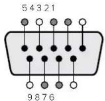
| Pln Function | |
| 1 Ground | |
| 2 Tx- (Data sent by router) | |
| 3 Rx+ (Data received by router) | |
| 4 Ground | |
| 5 NC (No connect) | |
| 6 Ground | |
| 7 Tx+ (Data sent by router) | |
| 8 Rx- (Data received by router) | |
| 9 Ground | |
Videohub RS-422 Router Control DB9 pin connections.
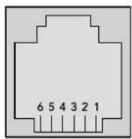
| Pin No. Function | |
| Pin 1 | TX + |
| Pin 2 | TX - |
| Pin 3 | GND |
| Pin 4 | GND |
| Pin 5 | RX - |
| Pin 6 | RX + |
Videohub RS-422 Router Control RJ11 pinout diagram.
This document describes the commands and parameters in the protocol that are relevant and supported by Videohub. Other commands and parameters specified in the Leitch protocol are accepted but ignored.
The RS-422 serial port is configured as 9600 N81.
The protocol is line-oriented, with a maximum length of 250 characters per command. Each command from the client should be terminated with a carriage-return ( r ). Each response from the server will be terminated with a carriage-return and line-feed ( r' n ).
Sources, destinations and levels are always specified in base-16, numbered from zero. Levels are always between 0 and 15 ("F"). Videohubs only have one valid level - level zero.
On connecting to the serial port, the client should send a carriage-return. The Videohub Server will respond with a > character prompt, which is not followed by a carriage-return or line-feed. Receiving the prompt indicates that a connection has been established. The same prompt will be issued after each command received by the Videohub Server.
In the following documentation, commands in orange and values in blue must be typed literally, including any spaces. In the following example of an immediate command using destination port 7 and source port 3, @ X:0/destination, source would be entered as: @ X:0/6, 2
Notifications
Once connected, if status reporting is enabled, the client will receive a notification message when a route changes on the Videohub Server. The notifications take one of two forms:
S:0destination,source Routing change
This message indicates that the specified source port is now routed to the specified destination.
V:0destination,source Preset routing notification
This message indicates that the current preset includes a route from the specified source to the specified destination.
Global Commands
All pass-through commands are preceded by an @ symbol and a space.
The following client commands are supported:
@ ! disable status reporting
Status reporting is disabled by default.
@ ? enable status reporting
Status reporting is enabled.
@ Z: reset routing table
Routing is reset so that the first source is routed to all destinations.
Immediate Commands
@ X:0/destination,source change route
@ X:0/destination,source/destination-2,source-2... change multiple routes
The specified source ports are routed to the specified destinations.
Any routing changes will trigger s: notifications
@ X?0destination request individual route status
The source routed to a the specified destination will be returned as an S: notification.
@ S?0 request all ports route status
Each source & destination port pair will be returned as s: notifications
Salvo Commands
@ P:0/destination,source queue route change
@ P:0/destination,source/destination-2,source-2... queue multiple route changes The specified routing changes are added to the current salvo for later execution.
@ P?0destination request individual port status in salvo
If a routing change for the specified destination port is queued, the route will be returned as a v: notification.
@ V?0 request all ports status in salvo
Each queued routing change in the salvo is reported as a v: notification.
@ B:C clear salvo
@ B:R clear salvo
Any queued changes are discarded and the salvo is reset.
B:E execute salvo
Any queued changes are executed and each routing change will be returned as an notification.
Saving and Loading Labels with Telnet in Mac OS
Normally you would use Blackmagic Videohub Setup to save and load labels between different Videohub routers and to backup your videohub settings. However, if for any reason you wish to use the Terminal, the instructions below let you save and load router label configurations via the Terminal.
![Blackmagics-iMac:~ timf$ telnet 192.168.25.253 9990 Trying 192.168.25.253... Connected to 192.168.25.253. Escape character is '^]'. PROTOCOL PREAMBLE: Version: 2.4 VIDEOHUB DEVICE: Device present: true Model name: Blackmagic Smart Videohub Unique ID: 7c2e0d0106df Video inputs: 16 Video processing units: 0 Video outputs: 16 Video monitoring outputs: 0 Serial ports: 0 INPUT LABELS: 0 Camera 1 1 Mini Converter 1 2 Hyperdeck 1 3 VTR 1 4 Teranex 1 5 PC Workstation 6 ATEM PGM 7 Camera 2 8 Mini Converter 2 9 Mac Workstation 10 Hyperdeck 2 11 VTR 2 12 Teranex 3 13 Hyperdeck 3 14 Hyperdeck 3 15 Input 16 OUTPUT LABELS: 0 Main Monitor 1 1 Main Monitor 2 2 Audio Monitor 1 3 Audio Monitor 2 4 ATEM Input 1 5 ATEM Input 2 6 ATEM Input 3 7 Hyperdeck 4 8 Hyperdeck 5 9 Hyperdeck 3 10 VTR 3 11 VTR 4 12 Teranex 4 13 Ultrascope 1 14 Ultrascope 2 15 Ultrascope 3](/content/2026/05/813338/images/455214690269d86fc8b9d36c8c78894aa889eb0b87ddceda0efd466436128c5e.jpg)
Saving Labels
1 Open the Terminal application which is located within the Applications > Utilities folder.
2 Type in "telnet" and a space followed by the IP of your Videohub, then another space and "9990", which is the default port number. For example type: telnet 192.168.25.253 9990. The Protocol Preamble screen will appear.
3 Copy the INPUT LABELS: text including the heading and paste into a word processor or simple text editor. Name this file "input labels" and save to your favorite location.
4 Copy the OUTPUT LABELS: text including the heading and paste into a word processor or simple text editor. Name this file "output labels" and save to your favorite location.
5 Close the telnet session by exiting the terminal window.
Loading Labels
1 Open the Terminal application with is located within the Applications > Utilities folder.
2 Type in "telnet" and a space followed by the IP of your Videohub, then another space and "9990", which is the default port number. For example type: telnet 192.168.25.253 9990. The Protocol Preamble screen will appear.
3 Open the "input labels" text file in your text editing program and copy the INPUT LABELS: text.
4 Paste this into the telnet session and press "return" twice. Telnet will respond with "ACK" and Videohub will update the input labels.
5 Open the "output labels" text file in your text editing program and copy the OUTPUT LABELS: text.
6 Paste this into the telnet session and press "return" twice. Telnet will respond with "ACK" and Videohub will update the output labels.
7 Close the telnet session by exiting the terminal window.
Saving and Loading Labels with Telnet in Windows
While you can save and load labels within Blackmagic Videohub Setup, you may also download and use PuTTY which is a free telnet client.
Setting up PuTTY
1 Start the application and in the "Host Name" field, type the IP of your Videohub and in the "Port" field type "9990", which is the default port number.
2 From the Connection type options select the "Telnet" radio button.
3 Select the "Terminal" tab and tick the "Implicit CR in every LF" checkbox.
4 Click the "Session" tab and save your session parameters by entering a name in the "Saved Sessions" field and clicking the "Save" button.
Saving Labels
Double click the PuTTY icon to start the application. Select your saved session from the list and click the "Load" button followed by the "Open" button. The Protocol Preamble screen will appear.
2 Copy the INPUT LABELS: text including the heading and paste into a word processor or simple text editor. Name this file "input labels" and save to your favorite location.
3 Copy the OUTPUT LABELS: text including the heading and paste into a word processor or simple text editor. Name this file "output labels" and save to your favorite location.
4 Exit the telnet session by closing the PuTTY window.
Loading Labels
1 Double click the PuTTY icon to start the application. Select your saved session from the list and click the "Load" button followed by the "Open" button. The Protocol Preamble screen will appear.
2 Open the "input labels" text file in your text editing program and copy the INPUT LABELS: text.
3 Right click in the PuTTY session to paste the copied section and press "Enter" twice. PuTTY will respond with "ACK" and Videohub will update the input labels.
4 Open the "output labels" text file in your text editing program and copy the OUTPUT LABELS: text.
5 Right click in the PuTTY session to paste the copied section and press "Enter" twice. PuTTY will respond with "ACK" and Videohub will update the output labels.
6 Exit the telnet session by closing the PuTTY window.
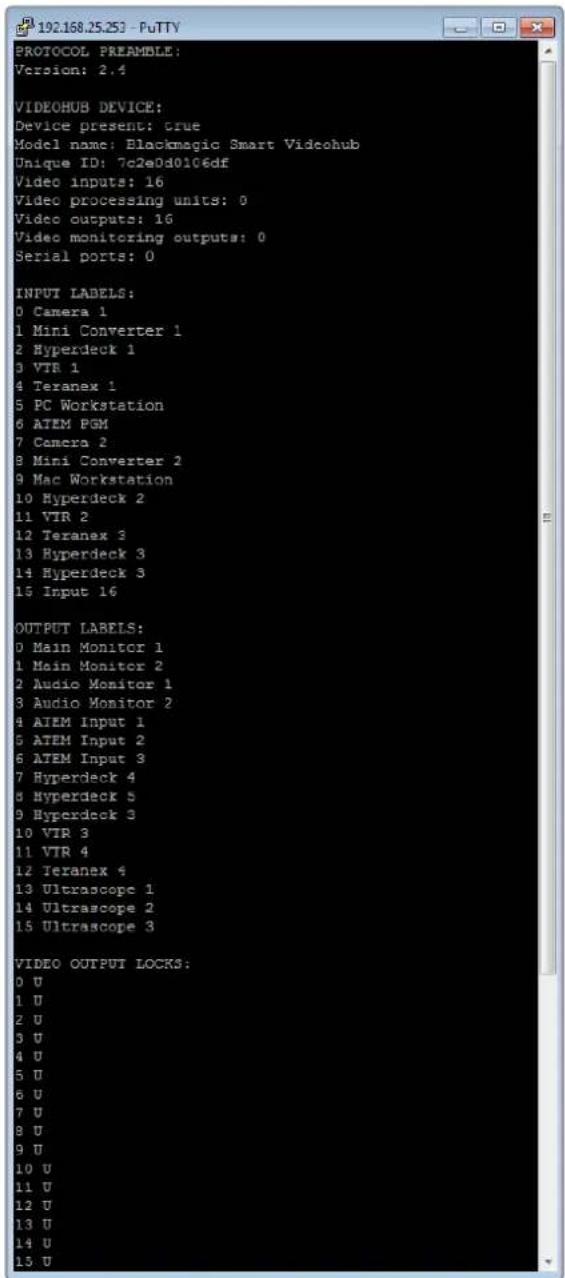
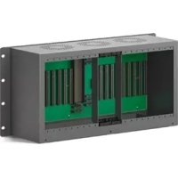
- Installation and Operation Manual
- Videohub
- Languages
- English 3
- Welcome
- Grant Petty
- Contents
- Getting Started
- Getting Started with Videohub
- Creating an IP Videohub with Teranex Mini IP Video 12G
- Plugging in Video
- To plug in your video sources:
- Controlling your Videohub
- There are two ways to control your Videohub:
- Blackmagic Videohub Software
- Smart Videohub CleanSwitch 12x12
- Connecting Videohub to a Network
- Connect to an Ethernet Network
- To connect Videohub to a network:
- Connect to a Videohub Server with USB
- To connect Videohub to the local area IP based network:
- Configuring your Videohub Server Settings
- Mac OS
- Windows
- Configuring Network Settings with a Built In Control Panel
- To set the IP address using the front control panel:
- Smart Videohub Control Panel
- Using the Smart Videohub Control Panel and LCD
- Menu Buttons Explained
- MENU
- VIDEO
- SRC
- DEST
- CLEAR
- TAKE
- Switching Routes with Smart Videohub
- Selecting the Cut Bus Feature
- To select between cut bus and take button modes:
- Locking and unlocking routes on Smart Videohub
- To lock a Destination
- To unlock a Destination
- Videohub Hardware Control Panels
- Introducing Videohub Hardware Control Panels
- Videohub Master Control Pro
- Videohub Smart Control Pro
- GPI and Tally Interface
- Connecting USB to Configure the Control Panel
- Plugging into an Ethernet Network
- Videohub Master Control and Videohub Smart Control
- To connect a Videohub control panel to the local area IP based network:
- Control Panel Button Diagnostics
- Pink flashing light
- Red flashing light
- Yellow flashing light
- No flashing light
- Updating the Software in your Videohub Controller
- About Routing Levels
- SDI 422
- SDI
- 422
- How to Select Sources and Destinations
- How to select devices by typing the Videohub port numbers
- How to select devices with the scroll wheel
- How to select devices using the customizable buttons and scroll wheel
- How to select devices using the numeric buttons and scroll wheel
- How to select devices using the customizable and numeric buttons together
- Locking and Unlocking Routes
- To lock a destination using Videohub Master Control:
- To unlock a destination using Videohub Master Control:
- Using Macros
- Using Videohub Smart Control Pro as a Cut-Bus Controller
- Using Videohub Smart Control Pro as an XY Controller
- To change routes:
- Labeling Pushbuttons
- To remove the buttons:
- Universal Videohub Routers
- Universal Videohub 288
- What you need to get started
- Universal Videohub 288 Crosspoint Card
- Router Control Cable
- Power Supply
- Building Universal Videohub 288
- Installing a Universal Videohub 288 Crosspoint Card
- Universal Videohub Status LEDs
- Installing Interface cards
- Installing a Universal Videohub Power Supply
- Installing a second Power Supply while Universal Videohub 288 is running
- Removing a Power Supply while Universal Videohub 288 is running
- Universal Videohub 72
- Universal Videohub 72 Crosspoint Card
- Building Universal Videohub 72
- Installing a Universal Videohub 72 Crosspoint Card
- Installing a Universal Videohub 450W Power Card
- SDI Interface Card
- Universal Videohub Interface Cards
- Universal Videohub Deck Control Cable
- 3G-SDI Videohub Routers
- Blackmagic 3G-SDI Videohub Routers
- Using the Smart Videohub Control Panel
- Videohub Router Monitoring
- Router Monitoring with Blackmagic MultiView 16
- Using the Built in Control Panel and LCD
- LCD and Home Screen
- HD video output format
- Audio input
- Multiview layout
- SRC and VIEW
- SOLO
- SET
- NUMBERS
- SRC, VIEW and SET
- SOLO and MENU
- To install your Blackmagic Videohub software
- Windows installation
- Mac OS installation
- Blackmagic Videohub Setup
- Network Settings
- Connect the Videohub to your computer via USB and follow these steps:
- Customizing Labels
- Customize Input Labels
- Customize Output Labels
- Customize Remote Labels and Port Directions
- Saving and Loading Labels
- Naming your Videohub
- Updating your Videohub's Internal Software
- Blackmagic Videohub Control
- Selecting a Videohub
- Adding Pushbuttons
- Viewing Routes
- Switching Routes
- Use TAKE Confirmation before Switching Routes
- Serial Control Settings
- Touchscreen Computers
- Apple iPad
- The initial Pushbutton interface
- Configuring Videohub Pushbuttons on the iPad
- Viewing and Changing Routes
- Installing the Videohub Software on iPad
- Downloading the Videohub iPad software through your iPad:
- Setting up the IP address in Videohub for iPad:
- Videohub Hardware Panel Setup
- Add Videohub Control
- Load/Save Settings
- Configuring Videohub Master Control Pro
- Backlight
- Creating Button Labels
- Configuring Videohub Smart Control Pro
- Number of Destinations
- Cut-Bus Configuration
- XY Controller Configuration
- Number of Macros
- Take Button
- Configuring GPIs
- Latch Video
- Momentary Hold Video
- Configuring Tally
- GPO Match
- Daisy Chaining Multiple GPI and Tally Interfaces
- Adding a GPI and Tally Interface Over a Network
- Setting up the GPI and Tally Interface
- Configuring the GPI and Tally Interface
- If you do not know the IP address of your Videohub:
- Controlling Blackmagic MultiView 16 with Videohub Software
- Connecting Blackmagic MultiView 16 to Videohub Control Software
- Configuring Network Settings on Blackmagic MultiView 16
- To configure your network settings:
- Developer Information
- Blackmagic Videohub Ethernet Protocol v2.3
- Summary
- LEGEND
- Protocol Preamble
- Device Information
- Initial Status Dump
- Status Updates
- Requesting Changes
- Requesting a Status Dump
- Checking the Connection
- Videohub RS-422 Protocol
- General
- Notifications
- Global Commands
- Immediate Commands
- Salvo Commands
- Saving and Loading Labels with Telnet in Mac OS
- Saving Labels
- Loading Labels
- Saving and Loading Labels with Telnet in Windows
- Setting up PuTTY
- Help
- Replacing a fan in Universal Videohub
- Replacing the fan in Broadcast Videohub
- Tips for Connecting SDI cables
- Getting Help
- Blackmagic Design online support pages
- Contacting Blackmagic Design support
- Checking the version currently installed
- How to get the latest updates
- Regulatory Notices
- Disposal of Waste of Electrical and Electronic Equipment Within the European Union.
- ISED Canada Statement
- Safety Information
- State of California statement
- Warning for Authorized Service Personnel
- Caution — Double Pole/ Neutral Fusing
- Warranty
- Limited Warranty
- インストール/オペレーションマニュアル
- ようこそ
- 目次
- 使用を開始する前に
- SRC/VIEW
- SOLO/MENU
- Videohubの名前付け
- ヘルプライン
- Chère cliente, cher client,
- Grilles de commutation Universal Videohub
- Pour bien démarrer
- SRC et VIEW
- Obtenir de l'aide
- Willkommen
- Inhaltsverzeichnis
- SRC und VIEW
- SOLO und MENU
- Blackmagic Design Online-Support
- California Proposition 65
- Bienvenido
- Dispositivo GPI and Tally Interface
- Primeros pasos
- Matrices Videohub SDI 3G
- SRC y VIEW
- Cómo obtener ayuda
- 安装操作手册
- 欢迎辞
- 关于指派级别
- 如何选择源信号和目标信号
- 通过Videohub Master Control解锁目标:
- Universal Videohub矩阵
- 初次使用前的准备工作
- Universal Videohub 288交叉点插卡
- Universal Videohub LED状态灯
- 3G-SDI Videohub矩阵
- Blackmagic 3G-SDI Videohub矩阵
- SRC和VIEW
- 为Videohub命名
- 配置Videohub Smart Control Pro
- 设置GPI and Tally Interface
- 配置GPI and Tally Interface
- 更换Broadcast Videohub的风扇
- 获得帮助
- 설치 및 사용 설명서
- 환영합니다
- 시작하기
- 3G-SDI Videohub 라우터
- SRC 및 VIEW
- Videohub 기기명 설정하기
- 지원 받기
- Замена вентилятора на Broadcast Videohub
- Как получить помощь
- Gentile utente
- Indice
- Scheda crosspoint
- Introduzione
- Matrici Videohub 3G-SDI
- Modelli
- SRC e VIEW
- II software Blackmagic Videohub
- Installazione
- Configurare GPI and Tally Interface
- Assistenza tecnica
- Bem-vindo
- Roteadores Videohub3G-SDI
- Roteadores Blackmagic Videohub 3G-SDI
- Usando o Smart Videohub Control Panel
- Configurando a GPI and Tally Interface
- Obter Ajuda
- Hoş Geldiniz
- İçindekiler
- Başlarken
- Universal Videohub 288 Crosspoint Kartı
- Güç Kaynağı
- SOLO ve MENU
- GPI and Tally Interface Kurulumu
- Yardım İçin
Brand : Blackmagic Design
Model : Smart Videohub
Category : Router