
Universal Videohub 72 - Router Blackmagic Design - Free user manual and instructions
Find the device manual for free Universal Videohub 72 Blackmagic Design in PDF.
| Product type | Modular SDI router for studio |
| Brand | Blackmagic Design |
| Model | Universal Videohub 72 |
| Dimensions (H x W x D) | 5U (22.2 cm) x 19 inches (48.3 cm) x 15.2 cm (6 inches) |
| Weight | Varies by configuration (approximately 15-25 kg) |
| Power supply | 450 W power supply card with up to 3 power supply units 150 W (sold separately) |
| Routing capacity | 72 SDI inputs and 72 outputs (up to 18 interface cards) |
| Supported video formats | SD-SDI, HD-SDI, 3G-SDI, DVB-ASI |
| Connectivity | Ethernet 10/100Base-T, USB 2.0 (type A to mini-B), RS-422, reference input |
| Built-in control panel | Yes, with LCD screen, scroll wheel, and shortcut buttons |
| Remote control | Via Ethernet network (Videohub Control software) or external hardware panels |
| Redundancy | Redundant power supply possible (up to 3 units), single crosspoint card (non-redundant) |
| Installation | Rack mount, hot-swappable cards |
| Maintenance | Hot-swappable fan replacement, dust filter cleaning |
| Operating temperature | Up to 40 °C |
| Warranty | 36 months (12 months for connectors, cables, fans, etc.) |
| Spare parts available | SDI interface cards (BNC or optical), 150 W power supply units, fans, crosspoint card |
| Repairability | User-replaceable modules (hot-swappable for most) |
| Control protocol | Videohub Ethernet Protocol v2.3, RS-422 |
| Included software | Blackmagic Videohub Setup, Control and Hardware Panel Setup (Mac/Windows) |
Frequently Asked Questions - Universal Videohub 72 Blackmagic Design
User questions about Universal Videohub 72 Blackmagic Design
0 question about this device. Answer the ones you know or ask your own.
Ask a new question about this device
Download the instructions for your Router in PDF format for free! Find your manual Universal Videohub 72 - Blackmagic Design and take your electronic device back in hand. On this page are published all the documents necessary for the use of your device. Universal Videohub 72 by Blackmagic Design.
USER MANUAL Universal Videohub 72 Blackmagic Design
Blackmagic GPI and Tally Interface
Languages
To go directly to your preferred language, simply click on the hyperlinks listed in the contents below.
Contents
English 3
日本語 94
François 186
Deutsch 278
Espanol 370
中文 462
554
Pycckn 646
Italiano 738
Portugues 830
Türkce 922
Polski 1014
YkpaHcBka 1106

Welcome
Thank you for purchasing Videohub!
We hope you share our dream for the television industry to become truly creative by allowing anyone to have access to the highest quality video.
Previously, high end television and post production required investing in millions of dollars of hardware, and professional SDI routers have always been way too costly for most people to afford. HD-SDI is even more expensive and, until now, only the largest post production and television facilities could afford HD-SDI routing. Videohub changes all that! Some Videohub models not only give you HD-SDI, but also the latest Ultra HD format, enabling you to pipe 4K 60p video around your studio using 12G SDI.
This instruction manual contains all the information you'll need to install your Videohub, although it's always a good idea to ask a technical assistant for help if you are not sure what IP addresses are, or if you don't know much about computer networks. Videohub is easy to install, however there are a few slightly technical preferences you will need to set after you install it.
Please check our website at www.blackmagicdesign.com and click the support page to download the latest updates to this manual and Videohub software. Lastly, please register your Videohub when downloading software updates so we can keep you updated when new software is released. We are constantly working on new features and improvements, so we would love to hear from you!
We hope you get years of use from your Videohub and have lots of fun connecting everyone in your facility together!

Grant Petty
CEO Blackmagic Design
Contents
Introducing Blackmagic Videohub 5
Getting Started 8
Connecting Power 8
Connecting Video 8
Controlling your Videohub 8
Switching a Route using the Built in
Control Panel 9
Shortcut Buttons 10
Using the Shortcut Buttons 11
Locking and Unlocking Routes 13
Connecting Videohub to a Network 14
Configuring Network Settings 15
Universal Videohub Routers 15
Universal Videohub 288 15
Building Universal Videohub 288 17
Universal Videohub 72 23
Building Universal Videohub 72 24
SDI Interface Card 28
Universal Videohub Interface Cards 29
Universal Videohub Deck Control Cable 30
Smart Videohub CleanSwitch 12x12 31
Videohub Hardware Control Panels 31
Videohub Master Control Pro 31
Videohub Smart Control Pro 32
Configuring the Control Panel 32
Connecting to an Ethernet Network 33
Control Panel Button Diagnostics 34
About Routing Levels 35
How to Select Sources and Destinations 36
Using Videohub Smart Control Pro as a Cut-Bus Controller 41
Using Videohub Smart Control Pro as an XY Controller 42
Labeling Pushbuttons 43
Blackmagic MultiView 16 43
Using the Control Panel 44
GPI and Tally Interface 46
Blackmagic Videohub Software 47
Blackmagic Videohub Setup 47
Labeling Inputs and Outputs 48
Setting Outputs to Cut Bus Mode 49
Creating Macros 49
Button Mapping 50
Setup Settings 51
Updating your Videohub 52
Blackmagic Videohub Control 53
Selecting a Videohub 53
Adding Pushbuttons 54
Viewing Routes 54
Switching Routes 54
Blackmagic Videohub Control at a Glance 55
Controlling Blackmagic MultiView 16 64
Videohub Hardware Panel Setup 66
Network Settings 66
Configuring Videohub Master Control Pro 68
Configuring Videohub Smart Control Pro 69
Configuring GPIs 72
73
Developer Information 77
Blackmagic Videohub Ethernet Protocol v2.3 77
Videohub RS-422 Protocol 83
Saving and Loading Labels with Telnet in Mac OS 86
Saving and Loading Labels with Telnet in Windows 87
Replacing a fan in Universal Videohub 89
Help 90
Regulatory Notices 91
Safety Information 92
Warranty 93
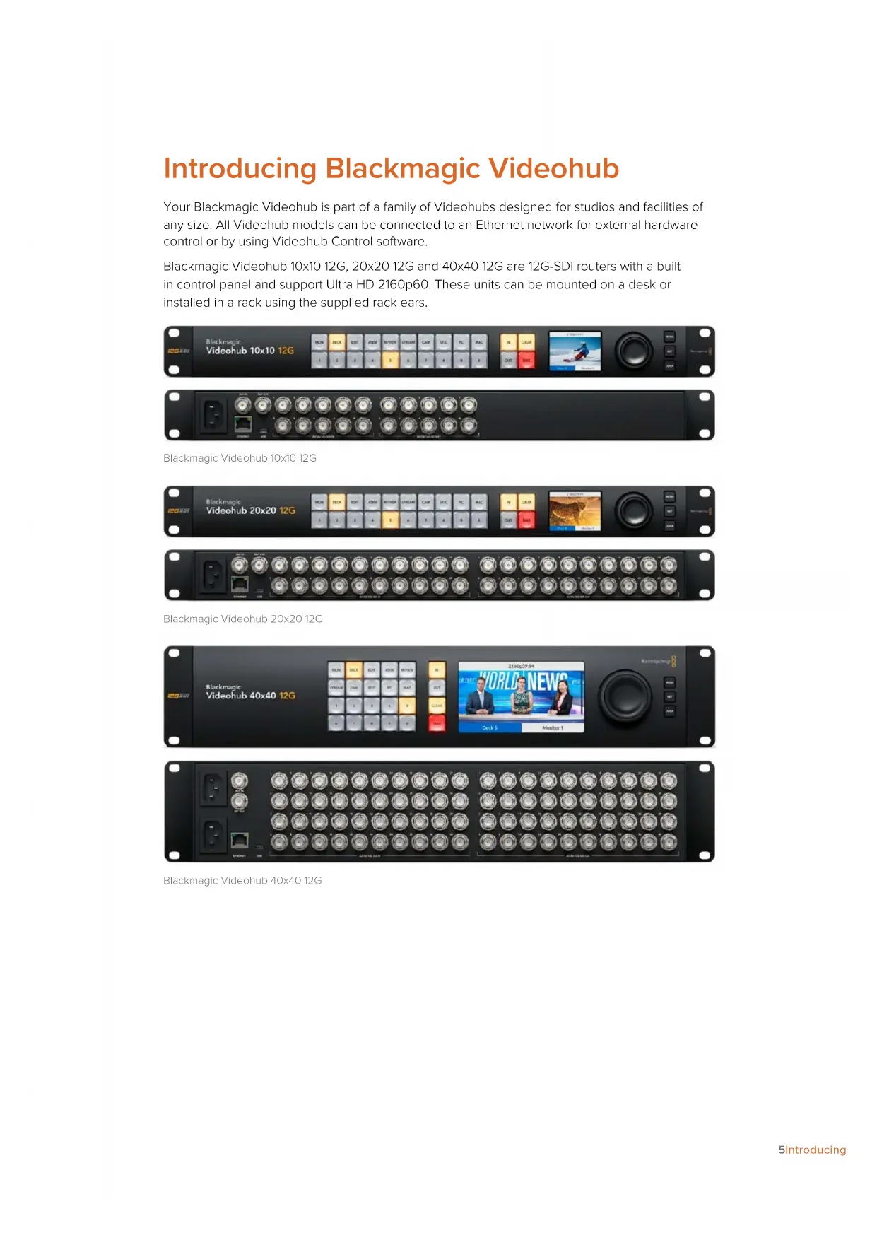
Introducing Blackmagic Videohub
Your Blackmagic Videohub is part of a family of Videohubs designed for studios and facilities of any size. All Videohub models can be connected to an Ethernet network for external hardware control or by using Videohub Control software.
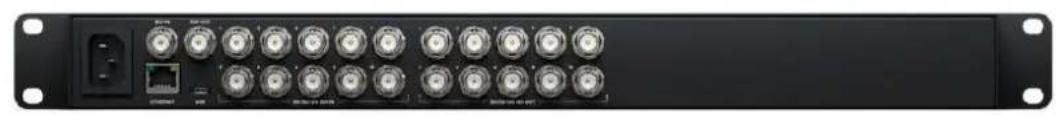
Blackmagic Videohub 10x10 12G, 20x20 12G and 40x40 12G are 12G-SDI routers with a built in control panel and support Ultra HD 2160p60. These units can be mounted on a desk or installed in a rack using the supplied rack ears.
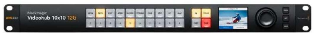
Blackmagic Videohub 10x10 12G
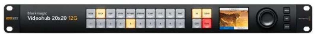
Blackmagic Videohub 20x20 12G

Blackmagic Videohub 40x40 12G
Universal Videohub 288 and 72 are rack mounted modular 3G-SDI routers for larger studios and facilities where a greater amount of HD equipment is connected.
Universal Videohub 288
Universal Videohub 72
Smart Videohub CleanSwitch 12x12 is a 6G-SDI rack mountable Videohub with a built in resynchronizer on each input so you can switch routes cleanly to monitors or directly to air.
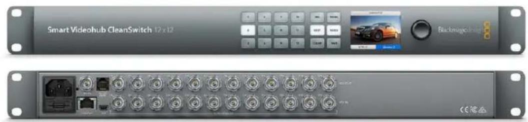
Smart Videohub CleanSwitch 12x12
Videohub Master Control Pro and Smart Control Pro are external hardware control panels that use the same filtering control available in Blackmagic Videohub 12G models. These units are designed to work with Universal Videohub 72 and 288, but can also be used to control any Videohub connected to the same Ethernet network.
Videohub Master Control Pro

Videohub Smart Control Pro
Getting Started
Getting started with Videohub is as simple as connecting power and plugging in your video sources and destination equipment.
Creating an IP Videohub with Teranex Mini IP Video 12G
If you are looking for information on the creation of an IP Videohub for routing Blackmagic Teranex Mini IP Video 12G units, refer to the Teranex Mini IP Video 12G manual which can be downloaded from www.blackmagicdesign.com/support.
Connecting Power
Connect power to the unit's power input via a standard IEC power connector.

When you first turn on a Videohub 12G model, the LCD will ask you to select your chosen language. Scroll through the languages using the spin knob and press the 'set' button to confirm your selection.
Connecting Video
1Connect your video sources to your Videohub's SDI inputs.
2Connect your destination equipment to your Videohub's SDI outputs.
The SDI connections will auto detect all supported video formats.
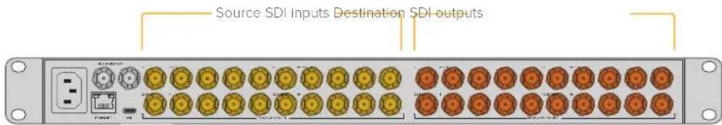
Connect your sources and destination equipment to your Videohub's SDI inputs and outputs
Controlling your Videohub
The fastest, most convenient way to control your Videohub is by using the unit's built in control panel. However, you can also change routes and settings remotely via USB or over Ethernet using an external Videohub hardware panel or by using the Blackmagic Videohub Control software. You can find more information about how to use the control software later in the manual.

The built in control panel lets you change routes and settings using the buttons, LCD and spin knob
Switching a Route using the Built in Control Panel
Switching a route is as simple as selecting the destination output and then selecting a source input to route to it.
Selecting the Source and Destination
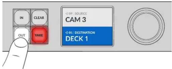
1Press the 'out' button to enable the destination output selection.
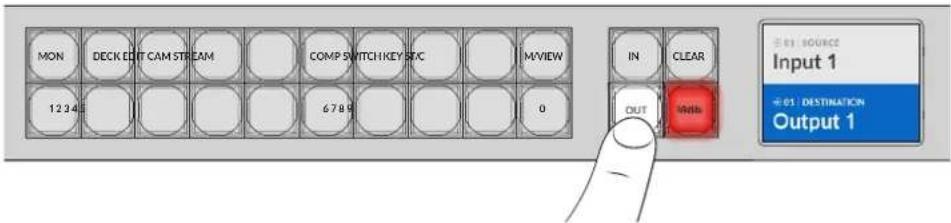
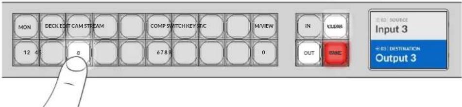
2Press a numbered pushbutton to select a destination output. Alternatively, you can use the spin knob to scroll through the destinations.
3Now press the in' button to enable the source input selection.
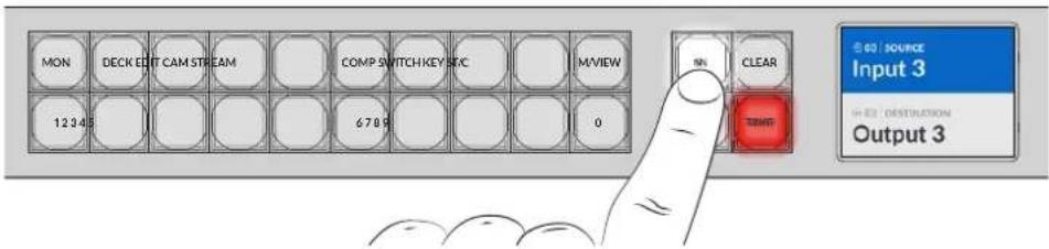
4 Press a numbered pushbutton to select a source input. Alternatively, you can also use the spin knob. When the source is selected, the 'clear' and 'take' buttons will flash indicating that you can confirm the route by pressing take, or cancel the route by pressing clear.
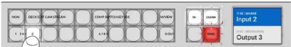
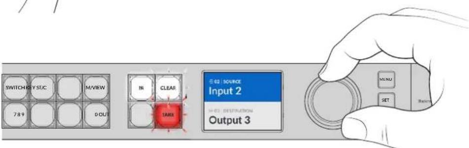
You can also use the spin knob to select your source and destination
5Press 'take'.
We have now completed a basic routing workflow using the source input and destination output buttons, plus the spin knob.
TIP To turn the 'in' button off, simply press it again to deselect it.
That's all there is to getting started with your Videohub! The next section of the manual will describe how to use the shortcut buttons.
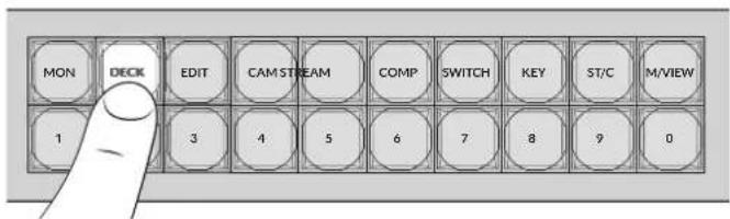
Shortcut Buttons
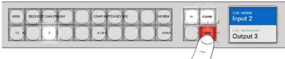
The labeled shortcut buttons above the numbered buttons let you make more specific selections using Videohub's built in filtering system.
Your Videohub is shipped with shortcut buttons already labeled to match common sources and destinations that are used in production facilities and studios. For example, 'DECK' for recording and playback decks, 'CAM' for cameras, 'EDIT' for edit bays, etc. When changing a route, you can narrow down your selection by pressing a shortcut button. This reduces the options to a smaller set, which can make the process faster when using larger Videohubs with a lot of equipment connected.
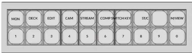
Use the shortcut buttons to take advantage of Videohub's alpha numeric filtering
A Note about Shortcut Buttons
Before you can use the shortcut buttons, you will need to label the inputs and outputs so the Videohub filtering system has labels to work with.
Labeling inputs and outputs is performed using Blackmagic Videohub Setup software. This utility is included in the free Videohub software available for download at the Blackmagic Support Center at www.blackmagicdesign.com/support
We recommend installing the setup software and labeling your Videohub's inputs and outputs, then returning to this section for information on how to use the shortcut buttons. If you have already labeled the inputs and outputs, please continue reading this section.
For all information regarding Videohub software refer to the 'Blackmagic Videohub Software' section.
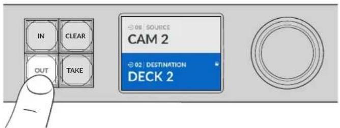
Using the Shortcut Buttons
After the inputs and outputs have been labeled, the shortcut buttons can use Videohub's filtering to make faster selections.
To use the shortcut buttons:
Select the Destination
1Press the 'out' button to enable the destination selection.
2Press the shortcut button labeled 'DECK'.
Your Videohub now makes all outputs available that include DECK in their label, filters out other destinations and then arranges them for selection on the numbered pushbuttons in numerical order.
3Press button '2' to select 'DECK 2'.
Button '2' will illuminate and you can see the selected output and destination on the LCD.

TIP If you have the LCD set to video monitoring you can see the video image currently routed to that destination plus the new source as you select it. Confirm the selection by pressing the 'take' button. Video monitoring can be enabled using the LCD menu or Blackmagic Videohub Setup.
Select the Source
1Press the 'in' button to enable the source selection.
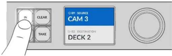
2Press the shortcut button labeled 'CAM'.

The filter now makes all inputs available that includes CAM in their label, filtering out other equipment and then arranges them on the numbered pushbuttons in numerical order.
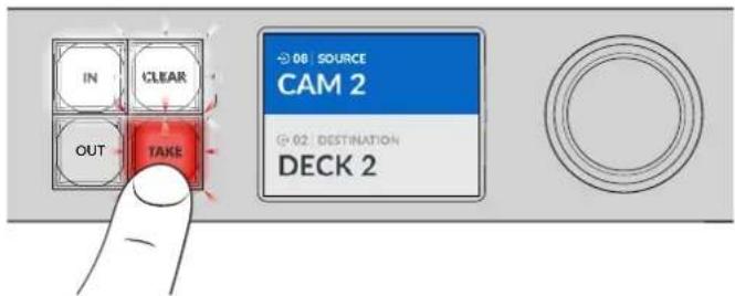
3Press button '2' to select 'CAM 2'.
Button '2' will illuminate and you can see the selected source and input on the LCD.
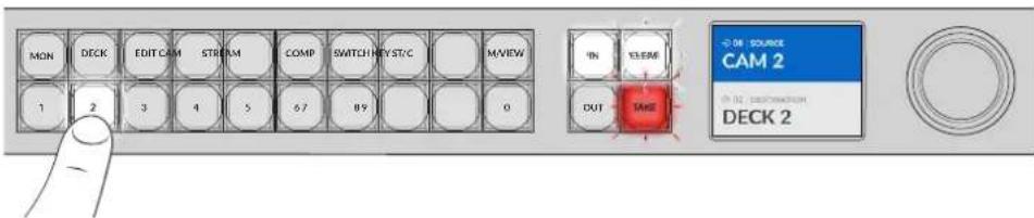
4Press the 'take' button to confirm and complete the routing change.
Locking and Unlocking Routes
Locking and unlocking routes with your Blackmagic Videohub can be set easily using the integrated front panel. Press the 'lock' button to lock the currently selected output and you will see a lock indicator appear next to its name on the LCD.
If you want to lock a different output:
1Press the destination button marked 'OUT'.
2Now select a new destination by pressing the numbered and shortcut pushbuttons or by using the spin knob.
3Press the 'lock' button.
You will see the lock indicator appear next to the output's name on the LCD. The lock button will also illuminate whenever that destination is selected to show that destination is locked and will not allow any new routes to be switched until it is unlocked.
To unlock the output, simply press the 'lock' button again.
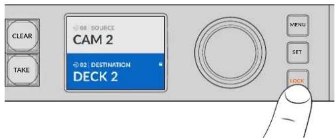
To prevent routes from being switched on a specific output, press the lock button to lock the output
Another way to lock an output is to hold the 'out' button down for 2 seconds until you see the lock indicator appear on the LCD. To unlock the output, simply hold the output button down for another 2 seconds.
When a destination is locked a lock icon will appear on the LCD
TIP If a locked destination is selected, the source or input buttons will no longer select a source.
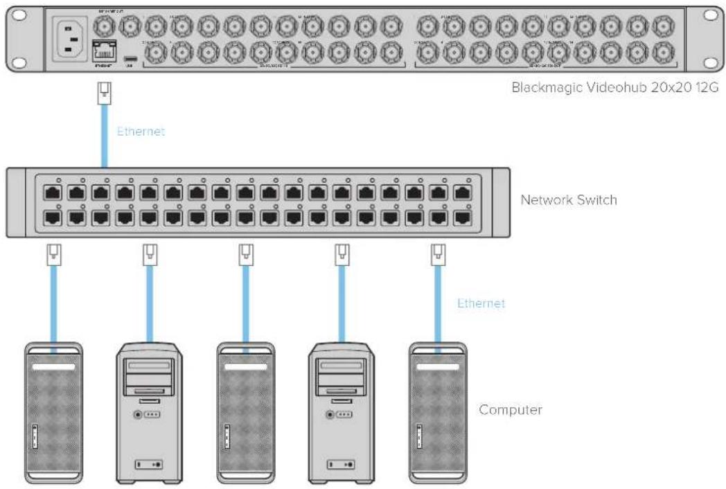
Connecting Videohub to a Network
All Videohub models have an Ethernet port and can connect directly to your Ethernet network switch or a computer on your local area IP based network. This lets you control your videohub using Blackmagic Videohub Control software on a computer connected to the same network, or by using an external Videohub hardware control panel.
To connect Videohub to a network:
1Connect power to your Videohub. On Universal Videohub models, make sure all power supplies are turned on.
2Connect your Videohub router to the network switch or computer Ethernet port with a standard RJ45 Ethernet cable.
For Videohub models with a built in control panel, you can use the spin knob and buttons to configure IP address in the LCD menu, or use Blackmagic Videohub Setup. For Universal Videohub models, set your network settings using Blackmagic Videohub Setup.
If you have a Universal Videohub 288 populated with two crosspoint cards, connect Ethernet cables to both for network failover redundancy. Your Universal Videohub 288 will have a single IP address, despite having two Ethernet connections to the network switch.
Network settings adjustments using Blackmagic Videohub Setup can only be adjusted when connected to your Videohub via USB. The next section of the manual will describe how to change network settings using the built in control panel.
Connecting to an Ethernet Network
NOTE For information on how to connect Videohub hardware control panels to a Videohub unit on the network, refer to Videohub Hardware Panel Setup.
Configuring Network Settings
Use your Videohub's built in control panel and LCD to configure network settings. Your router will be visible to other computers and hardware panels and these devices can then control the unit remotely and make routing changes.
To set the IP address using the front control panel:
1Press the 'menu' button to open the 'settings' menu.
2Use the spin knob to scroll down to 'network' settings. Press the 'set' button.
3Rotate the spin knob to select the entry you want to change and press 'set' to confirm.
4 Use the spin knob to change a number field. Press the 'set' button to confirm the change and move through the fields.
5Make sure you confirm the last change by pressing the 'set' button. You will know your settings are confirmed when the field entries are no longer highlighted.
6Press the 'menu' button to exit the settings menu and return to your source and destination status.
If required, the subnet and gateway address can be set using the same method.
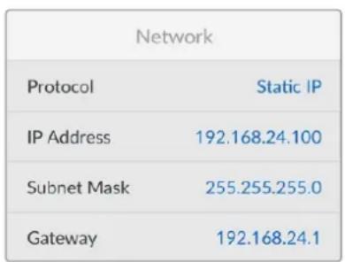
Press MENU to enter the network page and use the 'set' button and spin knob to set the IP address
Universal Videohub Routers
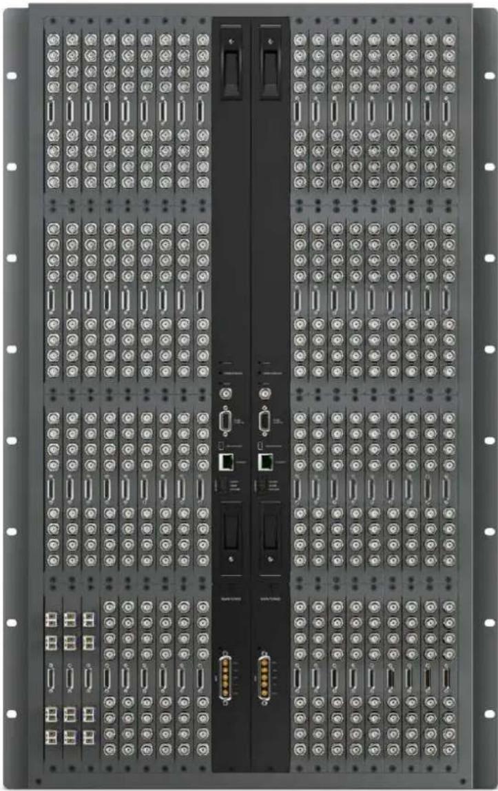
Universal Videohub 288
Universal Videohub 288 is a large, modular router ideally suited to very large facilities and broadcasters. It features a 72 card rack frame that can be filled with any combination of BNC SDI or optical fiber SDI interface cards.
When fully populated with two Universal Videohub 288 Crosspoint cards, two power cards, 72 interface cards and 72 deck control cables, Universal Videohub 288 provides 288 SDI inputs, 288 SDI outputs, 288 bidirectional RS-422 deck control ports, reference input, redundant crosspoint processor, redundant Ethernet networking, redundant power and powerful Videohub routing control software for Mac and Windows.
Occasionally, the internal software of the Universal Videohub 288 will need to be updated. Videohub Setup will prompt you if an update is required. The utility uses the USB 2.0 connection and you will need to provide a USB 2.0 type A to mini B male cable.
Universal Videohub 288 ships as an empty rack frame, except for a removable fan tray and fans. All other hardware components, such as SDI interface cards and power supplies, must be purchased and installed separately. Read the following section to help you decide which components you will need before you build your Universal Videohub 288.
See the 'SDI Interface Card' and 'Universal Videohub Interface Cards' sections for more information on the different interface cards available for your Universal Videohub.
Universal Videohub 288
Universal Videohub 288 Crosspoint Card
This module contains the crosspoint processor for switching video routes and changing deck control ports. Ethernet, USB and serial ports are located on the card for router control.
A Reference input is located on the card for connection to a tri-level sync or black burst genlock signal.
An Alarm light will illuminate on the card if user intervention is required, e.g., if inadequate cooling has caused Videohub to overheat. Alarm notification is supplied by the GPI (General Purpose Interface) output to other devices.
A Power Overload light will illuminate on the card if inadequate power is being supplied to the unit for the number of cards installed.
You will need a number 01 size Pozidriv screwdriver to install the Universal Videohub 288 Crosspoint card.
Router Control Cable
Remote router control is performed via 10/100Base-T Ethernet or serial. If router control is performed via Ethernet, the integrated Videohub Server is used. This means you only need to provide an Ethernet cable to connect Universal Videohub 288 to your Ethernet network switch.
Third party router controllers can control Universal Videohub 288 via Ethernet, or as an RS-422 slave device, for router crosspoint switching. Please refer to the Developer Information section of this manual for Videohub and RS-422 protocols.
Power Supply
When fully populated and running at maximum power consumption, Universal Videohub 288 can be powered by a single Universal Videohub Power Supply.
The Universal Videohub Power Supply package includes a power card with a single connection to a 1 RU size rack mount chassis which contains the power supply.
The Universal Videohub Power Supply chassis contains a universal power supply for use in all countries. You will need to provide a standard IEC cord with a C13 connector.
Universal Videohub 288 Crosspoint card Serial Cable
Universal Videohub Power Supply includes a power card, 1RU chassis and connecting power cable.
Standard RJ45 Ethernet Cable
Building Universal Videohub 288
25 rack units of space should be reserved for the installation of Universal Videohub 288 and two rack mount power supply chassis, allowing free space for heat dissipation. Only 23 RU is required if Universal Videohub 288 is mounted at the top of an open rack as heat can be dissipated from the top.
Universal Videohub 288 is 18 RU high and 6 inches thick. You can rack mount Universal Videohub 288 facing forwards or reversed, or even mount it in the rear of the rack to leave space for other equipment.
Universal Videohub 288 contains electrostatic sensitive devices. It is essential to discharge yourself of static electricity before handling any of these devices, just as you would when installing devices into a computer. We recommend the use of an antistatic wrist strap when handling any of these devices.
Installing a Universal Videohub 288 Crosspoint Card
Now that your Universal Videohub 288 has been mounted in a rack, it needs to be fitted with a crosspoint card. The crosspoint card is the brains of Universal Videohub and performs video route and deck control switching. Universal Videohub 288 Crosspoint cards are hot-swappable, meaning they are designed to be installed and removed while the Universal Videohub is running.
1 Hold the crosspoint card in a vertical orientation by its two levers. The BNC, Ethernet and other ports should be towards the bottom end of the card.
2Gently insert the card into its slot, ensuring the top and bottom edges follow the black guides.
3 Firmsly push both levers flat to fully engage the multi-pin connectors with the motherboard. Mating pins ensure that the card precisely engages with the motherboard without damaging the multi-pin connectors.
4 Use a number 01 size Pozidriv screwdriver to secure the two levers on the crosspoint card.
It is common to install a second crosspoint card for failover redundancy and we recommend doing this. If two crosspoint cards are installed, all video routes and port labels will be safely retained even if one card becomes faulty and has to be replaced. To remove the blanking plate from the right crosspoint card slot, you will need to use a number 02 size Pozidriv screwdriver.
Universal Videohub Status LEDs
The status LEDs marked 'alarm', 'power overload' and 'ref in' provide you with an indication of the current state of the Blackmagic Universal Videohub 288 Crosspoint. The following LED conditions provide specific information about the status of the unit.
Red 'alarm' LED
| ● | Off No error. Normal operation. |
| ● | On Error condition. Other error. Telnet into device to get error code. |
| 1 | 1 flash Error condition. Fan failure. |
| 3 | 3 flashes Error condition. No redundant power supply. |
Red 'power overload' LED
| ● | Off | Normal operation. Inactive / Slave mode. This should only be seen on a Blackmagic Universal Videohub 288 with 2 crosspoints. |
| ● | Slowly blinking Normal operation. Active / Master mode. | |
| ● | On Error condition. Power overload. Not enough power is being supplied. | |
White 'ref in' LED
| ● | Off Normal operation. | No reference connected. |
| ○ | On Normal operation. | Reference connected. |
TIP Blackmagic Universal Videohub 288 Crosspoint has amber colored LEDs mounted inside the device that should only be visible when the heatsink is removed for development purposes. However, in some cases a dim amber light may be visible through the hole that has been drilled for the 'alarm' LED. This is not an error condition.
A healthy Universal Videohub 288 Crosspoint should display the following:
| ● | Red ‘alarm’ LED Off. |
| ● | Red ‘power overload’ LED Slowly blinking or off. |
| ○ | White ‘ref in’ LED Solid white or off. |
Installing Interface cards
Installing a Universal Videohub SDI Interface or Universal Videohub Optical Interface is easy and the steps are the same for installing each type of interface card.
1 Hold the card in a vertical orientation with the identification LED at the top of the card. The identification LED looks like a pin hole near the top left of the top connector.
2 Gently insert the card along its guides until it plugs firmly into the PCI slot on the motherboard.
3 Use a number 02 size Pozidriv screwdriver to secure the card to the Universal Videohub frame.
See the 'SDI Interface Card' and 'Universal Videohub Interface Cards' sections for more information on the different interface cards available for your Universal Videohub.
Installing a Universal Videohub Power Supply
The Universal Videohub Power Supply package consists of a power card, a power cable and a 1 RU chassis containing the power supply. A second Universal Videohub Power Supply can be installed under the first power supply for failover redundancy. You will need to provide a standard IEC cord with a C13 connector for each power supply.
1 Ensure that any new power supplies are disconnected from any electrical source. Orient the power card so that the MAIN POWER label appears at the top of the card.
2 Insert the power card into either of the two power card slots.
3 Use a number 02 size Pozidriv screwdriver to secure the power card with its two screws. If you have a second power card, install it now into the spare power card slot.
4 Connect the power cable from the power card to the power supply. Tighten the thumb screws on both power connectors. Repeat this step if you have a second power card and second power supply. It does not matter which power card connects to which power supply.
5 Connect an IEC cord from each power supply to a mains wall socket and turn on the power.
Congratulations! Your Universal Videohub 288 is now ready to start routing video!
Installing a Universal Videohub SDI Interface Card
The Universal Videohub Power Supply consists of a power card which
is inserted into the Universal Videohub 288 and then connected to a
1 RU chassis located under the Universal Videohub 288
Installing a second Power Supply while Universal Videohub 288 is running
If you wish to install a redundant or replacement power supply while Universal Videohub 288 is already running from a power supply, please carry out the installation procedure in the following order:
1Ensure that the new power supply is disconnected from any electrical source.
2Orient the new power card so that the MAIN POWER label appears at the top of the card. Now insert the power card into the spare power card slot.
3Use a number 02 size Pozidriv screwdriver to secure the power card with its two screws.
4 If you are installing a redundant power supply for the first time, install the 1 RU chassis below the first power supply, leaving 1 RU of clearance between the two power supplies for heat dissipation. If you are installing a replacement power supply, install the replacement 1 RU chassis where the faulty unit was previously located.
5Connect the new power cable between the connectors on the new power card and the new power supply. Tighten the thumb screws on both power connectors.
6Connect an IEC cord from the new power supply to the wall socket and turn on the power.
Removing a Power Supply while Universal Videohub 288 is running
If you need to remove a faulty power supply while Universal Videohub 288 is running from another power supply, please carry out the removal procedure in the following order:
Switch off the power to the faulty power supply and unplug its IEC cord.
2Disconnect the power cable between the power card and the faulty power supply.
3Remove the faulty 1 RU chassis and associated power card. Ensure all components from the faulty unit are placed somewhere where they will not be confused with a new replacement unit.
Two Universal Videohub Power Supplies can be installed for power redundancy with the Universal Videohub 288
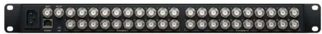
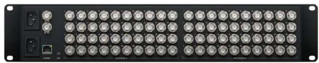
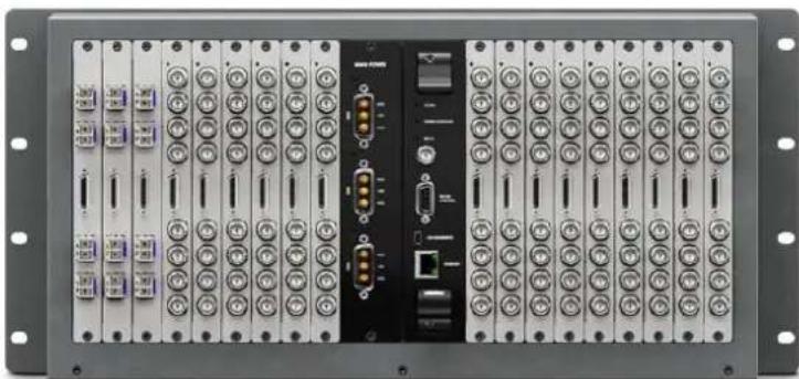
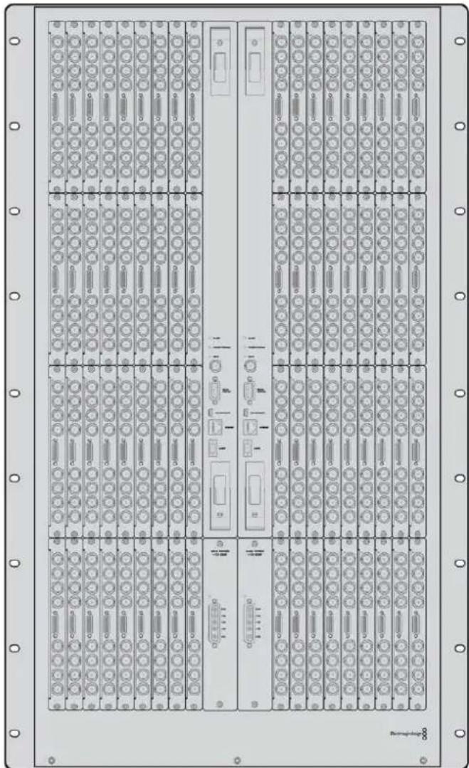
Universal Videohub 72
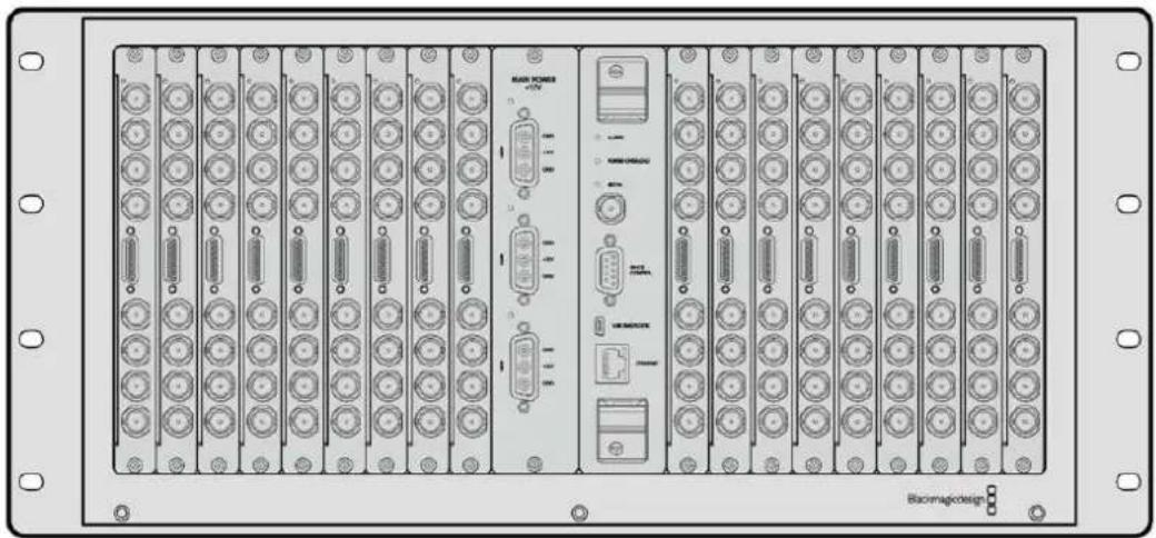
Universal Videohub 72 is a medium-sized modular router ideal for growing facilities. It features an 18 card rack frame that can be filled with any combination of BNC SDI or optical fiber SDI interface cards. When fully populated with a crosspoint card, a power card, 18 SDI interface cards and 18 deck control cables, Universal Videohub 72 provides 72 SDI inputs, 72 SDI outputs, 72 bidirectional RS-422 deck control ports, reference input, redundant power supply options and powerful Videohub routing control software for Mac and Windows.
Occasionally, the internal software of the Universal Videohub 72 will need to be updated. Videohub Setup will prompt you if an update is required. The utility uses the USB 2.0 connection and you will need to provide a USB 2.0 type A to mini B male cable.
Universal Videohub 72 ships as an empty rack frame, except for a removable fan tray and fans. All other hardware components, including SDI interface cards, deck control cables, crosspoint card and power supplies must be purchased and installed separately. SDI interface cards can be purchased as your facility grows and don't need to be installed all at once. This section is designed to help you decide which components you will need before you build your Universal Videohub 72.
See the 'SDI Interface Card' and 'Universal Videohub Interface Cards' sections for more information on the different interface cards available for your Universal Videohub.
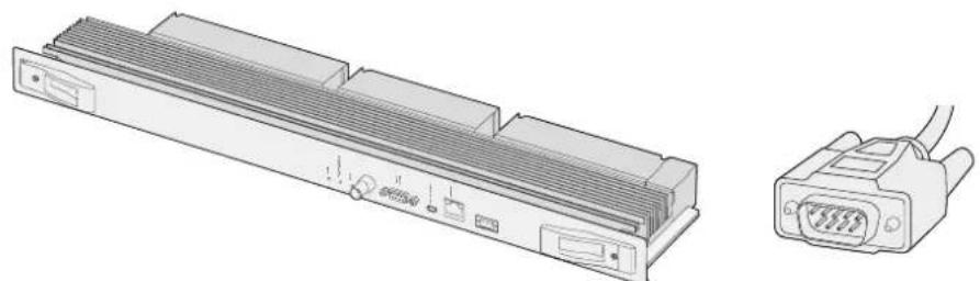
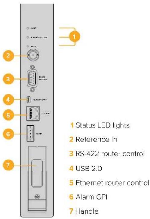
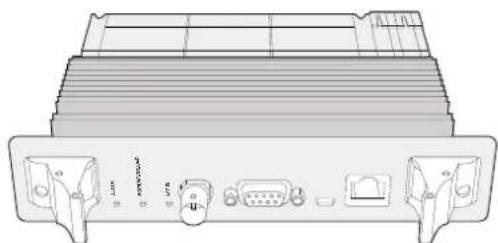
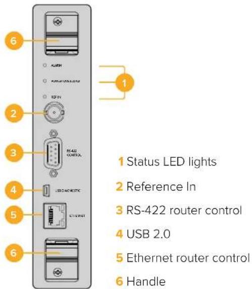
Universal Videohub 72 Crosspoint Card
This module contains the crosspoint processor for switching video routes and changing deck control ports. Ethernet, USB and serial ports are located on the card for router control.
A Reference input is located on the card for connection to a tri-level sync or black burst genlock signal.
An Alarm light will illuminate on the card if user intervention is required, e.g., if inadequate cooling has caused Videohub to overheat. Alarm notification is supplied by the GPI (General Purpose Interface) output to other devices.
A Power Overload light will illuminate on the card if inadequate power is being supplied to the unit for the number of cards installed.
Router Control Cable
Remote router control is performed via 10/100Base-T Ethernet or serial. If router control is performed via Ethernet, the integrated Videohub Server is used. This means you only need to provide an Ethernet cable to connect Universal Videohub 72 to your Ethernet network switch.
Third party router controllers can control Universal Videohub 72 via Ethernet, or as an RS-422 slave device, for router crosspoint switching. Please refer to the Developer Information section of this manual for Videohub and RS-422 protocols.
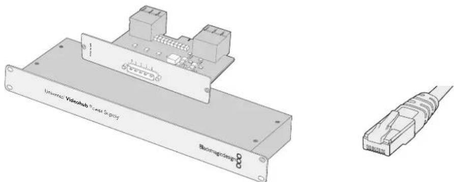
Universal Videohub Power Supply includes a power card, 1 RU chassis and connecting power cable.
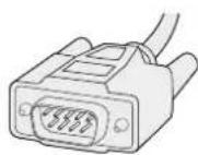
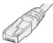
Serial Cable Standard RJ45
Ethernet Cable
Power Supply
The Universal Videohub 450W Power Card provides connections for up to three 150W brick-style power supplies, which must be purchased separately.
When fully populated and running at maximum power consumption, Universal Videohub 72 can be powered by two 150W brick power supplies. A third power supply can be connected to ensure continued operation should one power supply fail. The 150W power supplies are universal power supplies for use in all countries. You will need to provide a standard IEC cord with a C13 connector for each power supply. When fully populated with three power supplies, three mains power sockets will be required.
Building Universal Videohub 72
9 rack units of space should be reserved for the installation of Universal Videohub 72 including access space for the drop-down fan tray as well as free space for heat dissipation. Only 7 RU is required if Universal Videohub 72 is mounted at the top of an open rack. Universal Videohub 72 is 5 rack units high and 6 inches thick. You can rack-mount Universal Videohub 72 facing forwards or reversed, or even mount it in the rear of the rack to leave space for other equipment. 2 RU of space should be left above Universal Videohub 72 for heat dissipation unless mounted at the top of an open rack where there is no obstruction to airflow above.
Universal Videohub 72 contains electrostatic sensitive devices. It is essential to discharge yourself of static electricity before handling any of these devices, just as you would when installing devices into a computer. We recommend the use of an antistatic wrist strap when handling any of these devices.
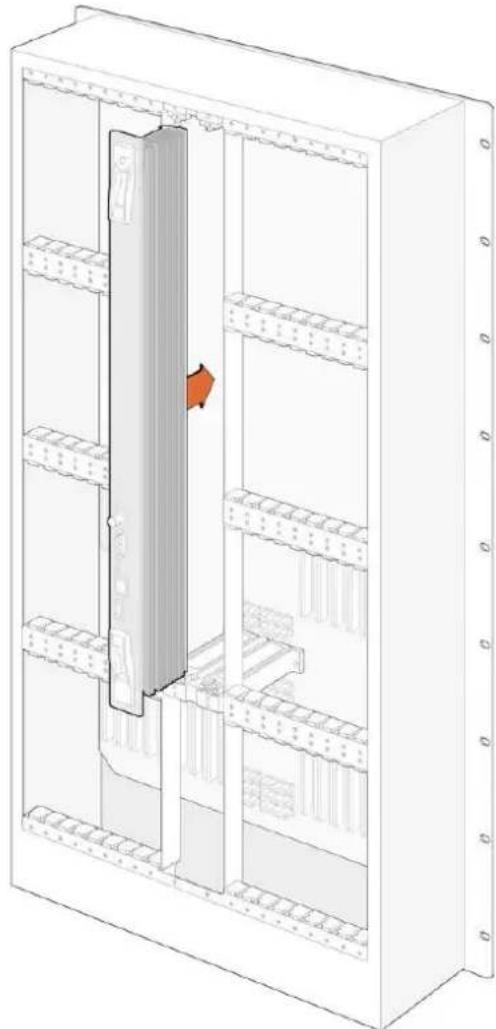
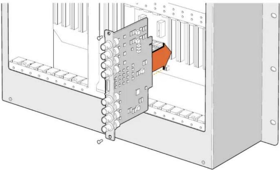
Installing a Universal Videohub 72 Crosspoint Card
Now that your Universal Videohub 72 has been mounted in a rack, it needs to be fitted with a crosspoint card. The crosspoint card is the brains of any Universal Videohub and performs video route and deck control switching. Universal Videohub 72 Crosspoint cards are hot-swappable, meaning they are designed to be installed and removed while the Universal Videohub is running.
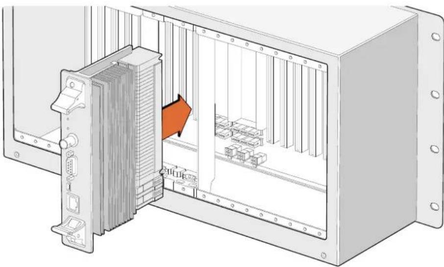
Installing a Universal Videohub 72 Crosspoint Card
1 Hold the crosspoint card in a vertical orientation by its two levers. The Ethernet port should be towards the bottom end of the card.
2Gently insert the card into its slot, ensuring the top and bottom edges follow the black guides.
3 Firmly push both levers flat to fully engage the multi-pin connectors with the motherboard. Mating pins ensure that the card precisely engages with the motherboard without damaging the multi-pin connectors.
4 Use a number 01 size Pozidriv screwdriver to secure the two levers on the crosspoint card.
Installing a Universal Videohub SDI Interface
Universal Videohub 72 Crosspoint
Universal Videohub Status LEDs
The status LEDs marked 'alarm', 'power overload' and 'ref in' provide you with an indication of the current state of the Blackmagic Universal Videohub 72 Crosspoint. The following LED conditions provide specific information about the status of the unit.
| Red 'alarm' LED | ||
| ● | Off No error. Normal operation | |
| ● | On Error condition. Other error. Telnet into device to get error code. | |
| 1 | 1 flash Error condition. Fan failure. | |
| 3 | 3 flashes Error condition. No redundant power supply. | |
| Red 'power overload' LED | ||
| ● | Off | Normal operation. Inactive / Slave mode. This should only be seen on a Blackmagic Universal Videohub 288 with 2 crosspoints |
| ● | Slowly blinking Normal operation. Active / Master mode. | |
| ● | On Error condition. Power overload. Not enough power is being supplied | |
| White 'ref in' LED | ||
| ● | Off Normal operation. | No reference connected. |
| ○ | On Normal operation. | Reference connected. |
TIP Blackmagic Universal Videohub 72 Crosspoint has amber colored LEDs mounted inside the device that should only be visible when the heatsink is removed for development purposes. However, in some cases a dim amber light may be visible through the hole that has been drilled for the 'alarm' LED. This is not an error condition.
A healthy Universal Videohub 72 Crosspoint should display the following:
| ● | Red ‘alarm’ LED Off |
| ● | Red ‘power overload’ LED Slowly blinking or off. |
| ○ | White ‘ref in’ LED Solid white or off |
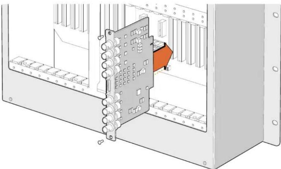
Installing Interface cards
Installing a Universal Videohub SDI Interface or Universal Videohub Optical Interface is easy and the steps are the same for installing each type of interface card.
1 Hold the card in a vertical orientation with the identification LED at the top of the card. The identification LED looks like a pin hole near the top left of the top connector.
2 Gently but firmly insert the card so that it follows its guides and plugs into the PCI slot in the motherboard. Use a number 02 size Pozidriv screwdriver to secure the interface card to the Universal Videohub frame.
See the 'SDI Interface Card' and 'Universal Videohub Interface Cards' sections for more information on the different interface cards available for your Universal Videohub.
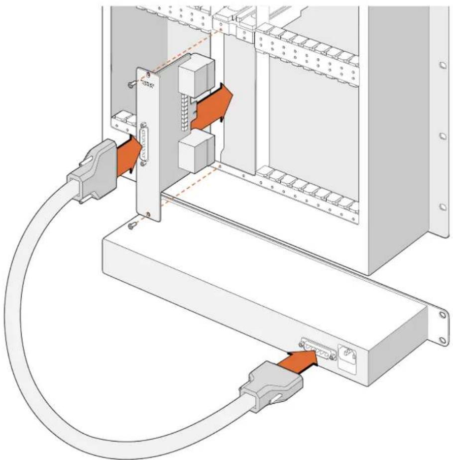
Installing a Universal Videohub 450W Power Card
The Universal Videohub 450W Power Card features three power connectors, which can be connected to 150W power supply bricks for up to 450W of power. This power card is suitable for powering a fully populated Universal Videohub 72 with two power supplies connected.
A third connected power supply provides failover redundancy should one power supply fail.
1 Ensure that the power supply is disconnected from any electrical source.
2 Orient the power card so that the MAIN POWER label appears at the top of the card.
3 Insert the power card into its slot on the motherboard. Use a number 02 size Pozidriv screwdriver to secure the power card with its two screws.
4 Connect three Universal Videohub 150W Power Supplies.
If you need to remove or replace the power card, power off and disconnect all connected power supplies before removing the power card.
If you have only partially populated your Universal Videohub 72 with interface cards, you might be able to power it with a single 150W power supply and preferably use a second power supply for failover redundancy. If you choose this option:
1 temporarily disconnect the second power supply and then check the Power Overload light on the crosspoint card after installing any cards.
2 If the Power Overload light illuminates, you will have to add a 150W brick power supply or remove some cards to ensure that all cards are receiving power.
3Reconnect the second power supply when you have finished checking the Power Overload light.
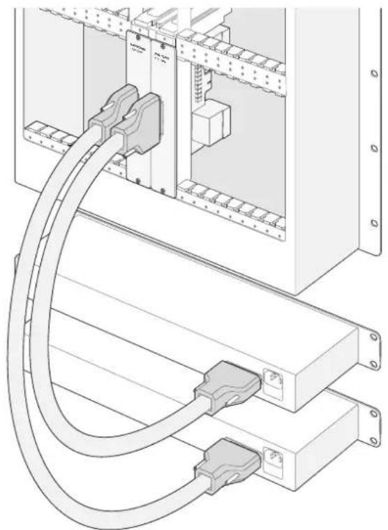
Universal Videohub 450W Power Card can be connected to three 150W power bricks
For peace of mind, we recommend connecting and powering the three power supplies at all times to ensure sufficient power, and power redundancy, with all card combinations.
If you need to remove or replace a 150W Power Supply while Universal Videohub 72 is still running, power off the brick while being careful to avoid switching off power to the remaining power supplies. Unplug the IEC cord and then unscrew and disconnect the power supply from the Universal Videohub 450W Power Card.
Congratulations! Your Universal Videohub 72 is now ready to start routing video!
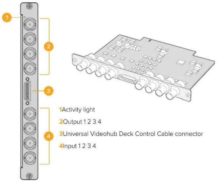
SDI Interface Card
SDI interface cards feature 4 SDI inputs, 4 SDI outputs and a connector for a Universal Videohub Deck Control Cable. All SDI connections support auto detection of SD, HD or 3G-SDI, and reclocking on all SDI outputs. Simultaneous routing of 2K, HD, SD video and DVB-ASI are supported with Universal Videohub. SDI interface cards are designed to be installed while Videohub is running and become active immediately. They do not require Videohub to be power cycled. You will need a number 01 and a number 02 size Pozidriv screwdriver to install the various cards.
There are two models of SDI interface cards that can be used with Universal Videohub:
Universal Videohub SDI Interface card with BNC connectors.
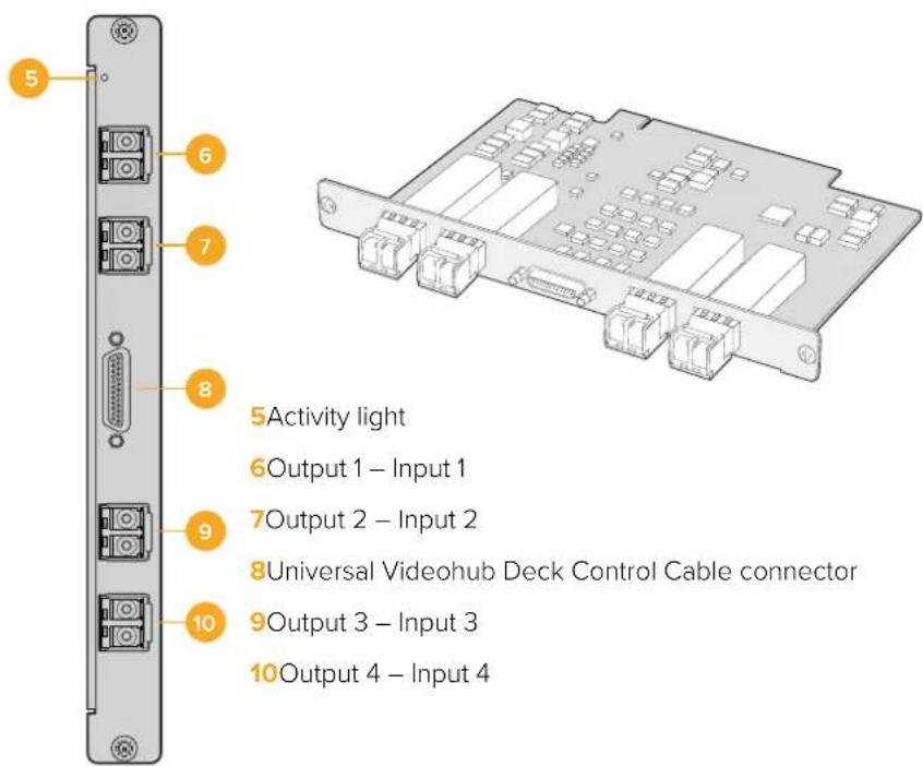
Universal Videohub Optical Interface card has standard SFP transceiver modules with 1310 nm laser drivers and receivers. Each module includes an LC connector port to be used with single-mode optical fiber cables.
Universal Videohub Interface Cards
Universal Videohub SDI Interface Card
Universal Videohub Optical Interface Card
Tips for Connecting SDI cables
The weight of copper-based SDI cables quickly adds up so it is advisable to use your rack to support the cables so that the full cable weight does not place undue stress on the BNC ports of your Videohub. This is particularly important with larger models of Videohub due to the weight of many SDI cables. Tying cable harnesses to the rack frame can provide support for large volumes of cabling.
It is also good practice to attach cables to the lowest BNC and optical fiber connectors first and then work upwards. This will avoid having to push lots of cables out of the way as you attach more cables in the future.
All Videohub models feature regular sized BNC ports, which make it easy to connect to other SDI equipment using regular SDI cables.
If you're connecting Videohub to SDI equipment that has miniature SDI connectors, such as DIN 1.0/2.3, we recommend using SDI cables that are terminated with a miniature connector at one end and a regular BNC at the other. Alternatively, an adapter cable can be connected to a regular SDI cable but this could prevent you from running long cables due to some loss of signal quality.
It's easy to connect and disconnect SDI cables to and from your Videohub. However as you attach more SDI cables, you might find it tricky to fit your fingers between the BNC connectors. You can use an inexpensive BNC removal tool, from third party vendors, to help make this task easy even when your Videohub has many cables connected.
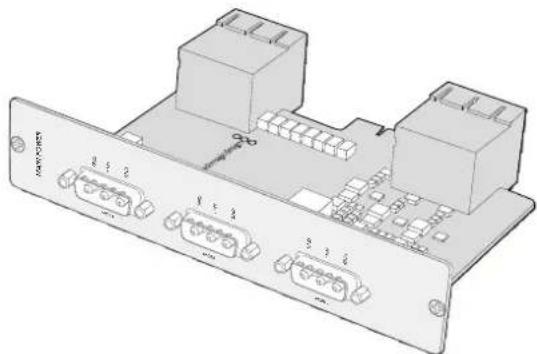
Universal Videohub Deck Control Cable
This cable features a single serial port at one end, for connection to both types of SDI interface cards, and four RS-422 deck control ports at the other end.
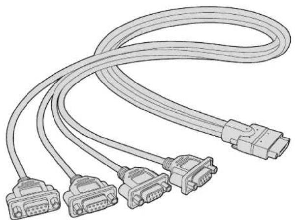
Universal Videohub Deck Control Cable
Smart Videohub CleanSwitch 12x12
When you need to cleanly switch between video sources to monitors or directly to air, you will need timed or genlocked signals. If you cannot guarantee perfectly timed source signals but you still need to clean switch, then you can use Smart Videohub CleanSwitch 12x12 as this model features resynchronization on all inputs so you get perfect clean feeds.

Smart Videohub CleanSwitch 12x12 includes full resynchronization on every input so the router automatically re times all inputs to ensure clean, glitch free switching between router cross points. Sources of the same resolutions and the same frame rate can even be output directly to air for smooth, cuts only production. The Smart Videohub CleanSwitch 12x12 will lock to the reference input or to Input 1 if no reference signal is connected. The video format of the reference signal and all inputs need to be identical for glitch free switching. You can still switch between mixed video formats, however they will not be synced.
Videohub Hardware Control Panels
Videohub hardware control panels are external panels designed to let you control Universal Videohub and any Videohub that is connected to the same network. Both panels support power over Ethernet plus on compatible network switches, which means you can power the panels using the same connection via Ethernet port 1 and you don't need to connect a separate power cable. The second Ethernet port does not support PoE but can be used to loop other equipment to the network.
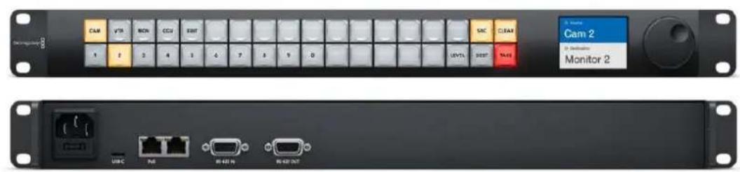
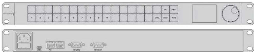
Videohub Master Control Pro
Videohub Master Control Pro is a 1 rack unit mountable control panel with 36 backlit pushbuttons, LCD, scroll wheel and Ethernet connectivity designed to perform Videohub crosspoint switching without using a computer. Videohub Master Control Pro can control all sources and destinations for any size of Videohub router, as well as RS-422 deck control.
Videohub Master Control Pro uses port labels to aid in fast selection of equipment using software. Pushbuttons can be configured and labeled to provide fast selection of common equipment types, e.g., cameras, decks and monitors. It also includes a loop through Ethernet port for connecting to additional control panels, Videohub routers or other network devices. Macro buttons illuminate green when enabled and each one can be configured to perform up to 16 simultaneous crosspoint switches.
Videohub Master Control Pro
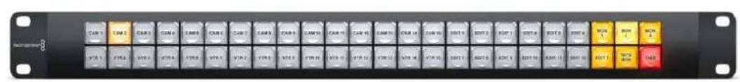
Videohub Smart Control Pro
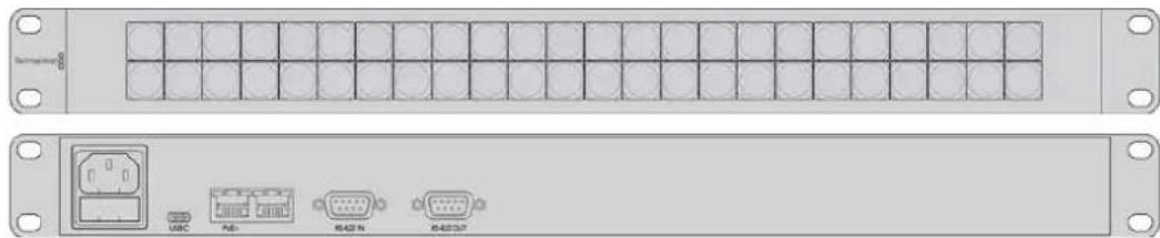
Videohub Smart Control Pro is a 1 rack unit mountable control panel with 48 backlit pushbuttons and Ethernet connectivity.
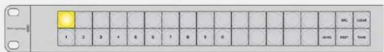
When configured for a single SDI destination, such as a monitor or deck, the pushbuttons can instantly switch between 48 different SDI sources on the same Videohub router. When configured for multiple SDI destinations, destination buttons become gold, source buttons become white and the lower right button can be configured as a take button and illuminates red. Macro buttons illuminate green when enabled and each one can be configured to perform up to 16 simultaneous crosspoint switches.
Videohub Smart Control Pro
Configuring the Control Panel
A USB connection to a computer is used to configure the network settings of the Videohub Controller.
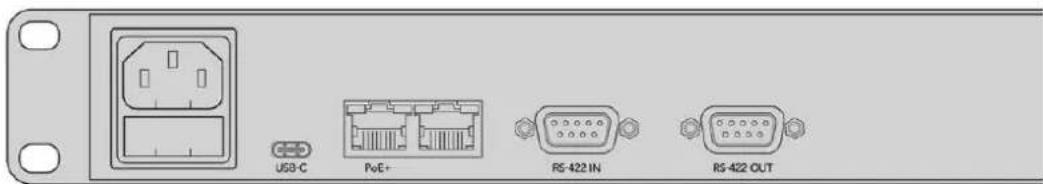
Plug the unit into a computer via USB-C to configure network settings
Connecting to an Ethernet Network
In most facilities, Videohub is usually shared via an Ethernet network switch so it can be controlled by computers on the network as well as by Videohub control panels. Connect the control panel to the network as you would any Videohub router.
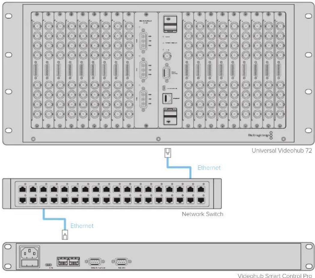
Videohub Smart Control Pro connected to a Universal Videohub 72 via an Ethernet network switch
NOTE The second Ethernet port does not support PoE+ so a unit connected to the second port will require its own power supply.
Control Panel Button Diagnostics
When power is first connected to a Videohub control panel, all the buttons will display their test lights in the following sequence: red, green, blue and white. The top left button of a Videohub control panel indicates its network status using the following diagnostic display:
Pink Flashing Light
Unit is attempting to acquire an IP address. The button should quickly become red if the unit is set to use a static IP address, or if the unit successfully acquires an IP address from the DHCP server.

Videohub control panel is attempting to acquire an IP address
Red Flashing Light
Unit has acquired an IP address and is attempting to connect to the Videohub Server.
Make sure the Videohub or Videohub server is powered on and connected via Ethernet.
IP address has been acquired and control panel is attempting to connect to the Videohub server
Yellow Flashing Light
Unit has connected to a Videohub server computer but the Videohub server is running an incompatible software or firmware version. Update Videohub with the latest version of the Videohub software and firmware and then power cycle the Videohub control panel.
Videohub Server is running an incompatible software or firmware version
No Flashing Light
Unit has successfully connected to the Videohub server and is ready to control the Videohub if solid white, or solid white and gold, lights can be seen.
Control panel has successfully connected to the Videohub server
If the top left button took several minutes to turn red, the unit has failed to acquire an IP address and has eventually provided itself with a self-assigned AutolIP address in the 169.254.xxx.xxx format. Unless you wish to use an AutolIP address, disconnect and firmly reconnect the network cables to ensure they are properly connected, check for faulty network cables and make sure the DHCP server has spare IP addresses available. Unplug and reconnect all power sources from the Videohub control panel so it will request a new IP address from the DHCP server. The button should quickly become red. The unit will only perform these diagnostics when it is not selected in Videohub Hardware Panel Setup software.
About Routing Levels
If your Videohub does not feature RS-422 remote deck control, Videohub Master Control will always show 'SDI' on its LCD and you don't need to read anything more about routing levels.
If your Videohub does include RS-422 remote deck control ports, you can use the LEVEL button on Videohub Master Control to reduce the list of sources and destinations by routing level.
Start by pressing the DEST button. Now press the LEVEL button to cycle through the routing levels:
SDI 422
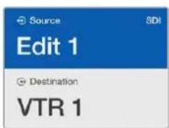
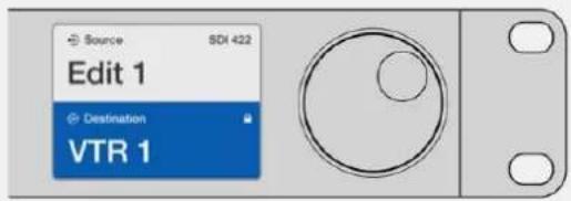
Choose this routing level to reduce the list of video equipment to devices with matching labels for their remote and SDI ports. This level is commonly used with SDI capture cards and VTR decks but cannot be used with cameras and monitors as they do not have RS-422 remote ports.

Choose the SDI 422 routing level if you only want to see SDI video equipment with RS-422 deck control. In this example, the capture card (Edit 1) and the deck (VTR 1) are listed because they both have SDI and RS-422 ports.
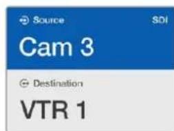
SDI
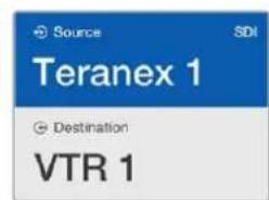
Lists all SDI sources and destinations. Choose this routing level if you want to see all SDI video equipment, i.e., cameras, monitors, capture cards and VTR decks, regardless of RS-422 connections.
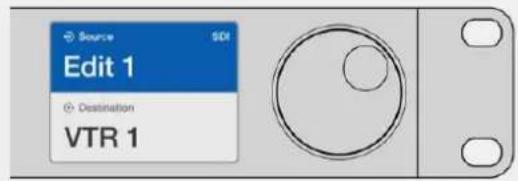
Choose the SDI routing level if you want to see all SDI video equipment. In this example, the capture card (Edit 1) and the deck (VTR 1) are listed because they both have SDI ports.
422
Choose this routing level if you want to reduce the list of video equipment to all devices with RS-422 deck control. This will list sources and destinations by the names of their RS-422 remote ports, regardless of whether there are any associated SDI ports and regardless of whether any associated SDI ports have matching labels or not. This level is commonly used with SDI capture cards and VTR decks but also lists remote control panels and servers used to control decks.

Choose the 422 routing level if you want to see all equipment with RS-422 remote deck control, including equipment with mismatched labels and also remote controllers. In this example, the capture card (Edit 1) has a mismatched label for its remote port (serial 1) and is only listed when the routing level is set to 422.

Front panel showing a new source has been selected.
How to Select Sources and Destinations
Videohub Master Control Pro provides several ways to select and switch your destinations and sources quickly, depending upon whether you have customized the port labels on your Videohub router or if you just want to enter port numbers directly.
Videohub Master Control Pro works in the same conceptual way as any other router control.
1Press the destination button marked 'DEST' to display a destination on the LCD. Use the pushbuttons or the scroll wheel to select the desired destination.
2Press the 'take' button to confirm.
3Press the source button marked 'SRC' and use the pushbuttons or scroll wheel to change the source.
4Press TAKE to confirm the route change.
Selecting units by typing the Videohub port numbers
If you've chosen to keep the default labels for all Videohub SDI and remote ports, you can simply type the port numbers to make a routing change. This method is fast but requires that you remember port numbers or have devised a system for knowing what equipment is connected to each Videohub port.
Press the destination button marked 'DEST'. The destination field will be highlighted blue on the LCD.
2If your Videohub router has RS-422 remote control, press the LEVEL button until you have set the appropriate routing level for your equipment. Otherwise you can skip this step.
3 Type in the destination port number using the numeric pushbuttons. Each button will flash gold once as you press it. The destination will be displayed on the LCD. If you make a mistake, press the white 'clear' button and retype the port number.
Press the source button marked 'SRC'. The source field will be highlighted blue on the LCD.
5 Type in the source port number using the numeric pushbuttons. Each button will flash white once as you press it. The source will be displayed on the LCD. If you make a mistake, press the white 'clear' button and retype the port number.
The 'take' button will flash red, awaiting your confirmation of the route change. Press 'take' and the route will change immediately. Otherwise, press 'clear' and no route change will take place. Videohub Master Control returns to its idle state with the latest route displayed on the LCD.
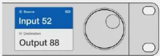
If you've chosen to keep the default labels for all Videohub SDI and remote ports, you can simply type the port numbers to make a routing change. In this example, press the destination button marked 'DEST' and then type the port number 88. Then press source button and type the port number 52. Press 'take' to confirm the route change.
Selecting Units using the Scroll Wheel
Regardless of whether or not you've customized the Videohub port labels, you can always use the scroll wheel to browse through a list of sources and destinations. This is the slowest method but is useful if you want to see the list of all available equipment and ports.
Press the destination button marked 'DEST'. The destination field will be highlighted blue on the LCD.
2 If your Videohub router has RS-422 remote control, press the 'level' button until you have set the appropriate routing level for your equipment. Otherwise you can skip this step.
3Scroll the wheel forwards or backwards until the desired destination is found. The destination will be displayed on the LCD.
4Press the source button marked 'SRC' so it illuminates white. The source field will be highlighted blue on the LCD.
5 Scroll the wheel until the desired source is found. The source will be displayed on the LCD.
The 'take' button will flash red, awaiting your confirmation of the route change. Press 'take' and the route will change immediately. Or press 'clear' and no route change will take place. Videohub Master Control returns to its idle state with the latest route displayed on the LCD.
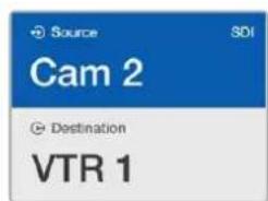
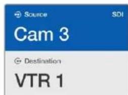
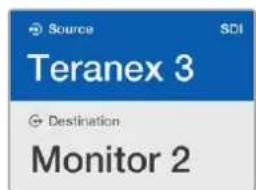
In this example, the scroll wheel is being used to list all sources that can be routed to the destination VTR 1, based upon the SDI routing level. When the scroll wheel is rotated, the names of source equipment are progressively displayed to make it very easy to find the desired video source.
Selecting Units using Customizable Buttons and the Scroll Wheel
If you have customized the Videohub port labels, you can use the customizable buttons and scroll wheel together to find a short list of sources and destinations. This method is fast and intuitive because you only have to scroll through a short list of equipment and you don't have to remember any port numbers. This method is very helpful if you label types of equipment together by name, e.g., VTR, Cam and Mon.
1 Press the destination button marked 'DEST'. The destination field will be highlighted blue on the LCD.
2If your Videohub router has RS-422 remote control, press the LEVEL button until you have set the appropriate routing level for your equipment. Otherwise you can skip this step.
3Press a button you have customized for a type of destination equipment, e.g., VTR. The button should light up gold.
4 Scroll the wheel forwards or backwards until the desired destination is found. In this example, the destination VTR will be displayed on the LCD. If you make a mistake, press the white 'clear' button and scroll until the correct destination is displayed.
Press the source button marked 'SRC'. The source field will be highlighted blue on the LCD.
6Press a button you have customized for a type of source equipment, e.g., a capture card. The button should light up white.
7 Scroll the wheel forwards or backwards until the desired source is found. In this example, the source capture card will be displayed on the LCD. If you make a mistake, press the white 'clear' button and scroll until the correct destination is displayed.
The 'take' button will flash red, awaiting your confirmation of the route change. Press 'take' and the route will change immediately. Otherwise, press 'clear' and no route change will take place. Videohub Master Control will then return to its idle state with the latest route displayed on the LCD.
If any button you have customized for either a source or destination flashes but does not stay lit, Videohub Master Control is preventing you from selecting the button because the equipment type has not been labeled as a source or destination device or does not match the current routing level. For example, cameras should not usually be set as destination devices, monitors should not be set as source devices and won't match the RS-422 routing level. Refer to Configuring Videohub Master Control Pro for steps on how to change this.
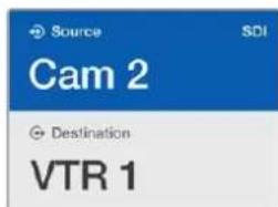
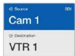
In this example, a customized Cam button has been selected so only cameras will be listed as sources, on the LCD, when the scroll wheel is rotated. This provides a fast way to find a video source because you only have to scroll through a short list of equipment.
Selecting Units using Numeric Buttons and the Scroll Wheel
If you have customized the Videohub port labels with numbers, you can use the numeric buttons and scroll wheel together to find a short list of sources and destinations. This method is fast and intuitive because you only have to scroll through a short list of equipment and you don't have to remember any port numbers. This method is very helpful if you label groups of equipment together by numbers, perhaps to represent locations. For example, all the equipment in Studio 3 could be labeled VTR3, Edit 3, Cam 3A, Cam 3B, Mon 3A and Mon 3B etc.
1 Press the destination button marked 'DEST'. The destination field will be highlighted blue on the LCD.
2 If your Videohub router has RS-422 remote control, press the 'level' button until you have set the appropriate routing level for your equipment. Otherwise you can skip this step.
3Using the numeric pushbuttons, type the destination number, e.g., 3 for Studio 3. Each numeric button will flash gold as you press it.
4 Scroll the wheel forwards or backwards until the desired destination is found. In this example, any of VTR 3, Edit 3, Mon 3A or Mon 3B could be displayed on the LCD. If you make a mistake, press the white 'clear' button and select another destination number.
Press the source button marked 'SRC'. The source field will be highlighted blue on the LCD.
Using the numeric pushbuttons, type the source number, e.g., 3 for Studio 3. Each numeric button will flash white as you press it.
7 Scroll the wheel forwards or backwards until the desired source is found. In this example, any of VTR 3, Edit 3, Cam 3A or Cam 3B could be displayed on the LCD. If you make a mistake, press the white 'clear' button and select another source number.
8 The 'take' button will flash red, awaiting your confirmation of the route change. Press 'take' and the route will change immediately. Otherwise, press 'clear' and no route change will take place. Videohub Master Control will then return to its idle state with the latest route displayed on the LCD.
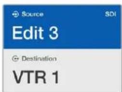
In this example, the numeric button "3" has been selected so only video sources with a "3" in their label will be listed, on the LCD, when the scroll wheel is rotated. This provides a fast way to find a video source because you only have to scroll through a short list of equipment based upon a group number, e.g. only list the equipment in Studio 3.
Selecting Units using Both Customizable and Numeric Buttons
If you have customized the Videohub port labels with names and numbers, you can use the customizable buttons and numeric buttons together to directly select sources and destinations. This method is very fast and intuitive because you don't have to scroll through a list of equipment and you only have to remember how many of each type of equipment you have, e.g., two VTRs and four monitors.
This method is very helpful if you label types of equipment by name and number, e.g., VTR 01, VTR 02, Cam 01, Cam 02, Cam 03, Mon 01, Mon 02, Mon 03 and Mon 04.
1 Press the destination button marked 'DEST'. The destination field will be highlighted blue on the LCD.
2If your Videohub router has RS-422 remote control, press the LEVEL button until you have set the appropriate routing level for your equipment. Otherwise you can skip this step.
3Press a button you have customized for a type of destination equipment, e.g., VTR. The button should light gold.
4Type in the destination equipment number using the numeric pushbuttons, e.g., 07 for VTR 07. Each numeric button will flash gold as you press it.
Press the source button marked 'SRC'. The source field will be highlighted blue on the LCD.
6Press a button you have customized for a type of source equipment, e.g., a capture card. The button should light white.
7Type in the source equipment number using the numeric pushbuttons, e.g., 03 for the capture card Edit 03. Each numeric button will flash white as you press it.
8 The 'take' button will flash red, awaiting your confirmation of the route change. Press 'take' and the route will change immediately. Otherwise, press 'clear' and no route change will take place. Videohub Master Control will then return to its idle state with the latest route displayed on the LCD.
If any button you have customized for either a source or destination flashes but does not stay lit, Videohub Master Control is preventing you from selecting the button because the equipment type has not been labeled as a source or destination device or does not match the current routing level. For example, cameras should not usually be set as destination devices, monitors should not be set as source devices and won't match the RS-422 routing level. Refer back to Creating Button Labels in Configuring Videohub Master Control Pro for steps on how to change this.
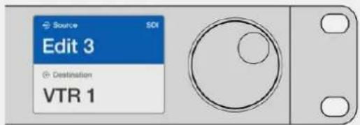
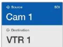
If you know that you want Edit 3 as the source, and VTR 1 as the destination, you can select the route directly without any scrolling being necessary. In this example, press the destination button marked 'DEST', press the customized VTR button and then press 1. VTR 1 will be shown in the destination field. Now press the source button marked 'SRC', press the customized Edit button and then press 3. "Edit 3" will be shown in the source field. Finally, press 'take' to confirm the route change.
Locking and Unlocking Routes
To lock a destination using Videohub Master Control:
1Set the destination and source using whichever method you prefer. Once the route has been set, Videohub Master Control will return to its idle state.
Press the destination button marked 'DEST'. The destination field will highlight blue on the LCD.
3 If the desired route is not already displayed on the LCD, use the pushbuttons and/or scroll wheel to find the destination to be locked.
4 Press and hold the gold destination button until a lock icon appears in the destination field of the LCD.
5Press 'destination' again to return Videohub Master Control to its idle state and the destination field will revert to gray.
The destination field shows a lock icon if the destination is locked.
To unlock a destination using Videohub Master Control:
1Press the destination button marked 'DEST'. The destination field will highlight blue on the LCD.
2 If the desired route is not already displayed on the LCD, use the pushbuttons and/or scroll wheel to find the destination to be unlocked. The destination field will show a lock icon for the locked destination.
3Press and hold the gold DEST button until the lock icon disappears from the destination field of the LCD.
4Press DEST again to return Videohub Master Control to its idle state and the destination field will revert to gray.
Using Macros
If you press a green macro button, it will simultaneously make the crosspoint changes you have previously configured in Videohub Hardware Panel Setup. Each button can be configured with up to 16 crosspoint routes. If you have the Take button enabled, the simultaneous change of routes will only take place when you confirm by pressing the Take button. If for any reason the macro cannot be performed, the button will flash.
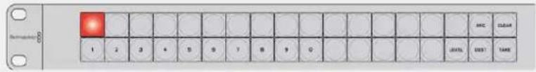
Using Videohub Smart Control Pro as a Cut-Bus Controller
If Videohub Smart Control Pro has been configured as a Cut-Bus controller, the destination device has already been chosen and you only need to choose a video source.
1 Select a white video source button. The button will light up to distinguish it from the other sources. The video source will immediately connect and be viewable on the destination device.
2 If the Take button has been enabled, the new source button and the Take button will flash. The route change will only take place when you confirm by pressing the Take button.

Videohub Smart Control Pro configured as a Cut-Bus controller and with a Take button
Using Videohub Smart Control Pro as an XY Controller
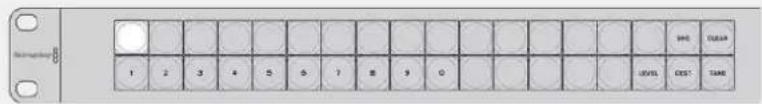
If Videohub Smart Control Pro has been configured as an XY controller, destination buttons light up gold and source buttons light up white. When working with multiple destinations, always select a destination button before selecting a source button.
To change routes:
1 Select a gold destination button and it will light up brightly to distinguish itself from the other destination buttons. If a video source has previously been connected to this destination, its button will light up white.
2To connect a new source to the destination, press the desired video source button. The video source will immediately be connected and viewable on the destination device. The new source button will be brightly lit and the previous source button will dim to normal. To change another route, select another destination button and then select a new source button.
3 If the 'take' button has been enabled, the new source button and the 'take' button will flash. The route change will only take place when you confirm by pressing the 'take' button.
Locking and Unlocking Routes
To lock a destination, press and hold the desired destination button until it turns blue. The corresponding source button will illuminate. If you attempt to change sources for a locked destination, the destination button will flash blue. To unlock a destination, press and hold the button until it returns to the standard gold color.
Using Macros
If you press a green macro button, it will simultaneously make the crosspoint changes you have previously configured in Videohub Hardware Panel Setup. Each button can be configured with up to 16 crosspoint routes. If you have the Take button enabled, the simultaneous change of routes will only take place when you confirm by pressing the Take button. If for any reason the macro cannot be performed, the button will flash.

Videohub Smart Control Pro configured as an XY controller and with a Take button
Labeling Pushbuttons
Videohub Master Control Pro, Videohub Smart Control Pro and Videohub 12G models have removable pushbuttons that provide access for labeling.
Included with the software installer is a 'Videohub control labels' folder containing a PDF template file. Fill out and print the PDF file labels, then cut out the squares to be inserted into the buttons.
To remove the buttons:
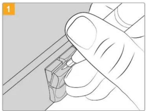
The button keycaps can be easily removed using a small flathead screwdriver.
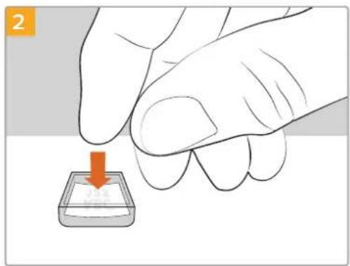
Loosely place your new printed label into the upturned clear keycap.
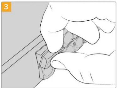
Replace the keycap by aligning it onto the button and gently pushing until you feel it click into place.
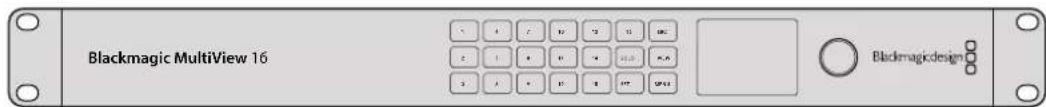
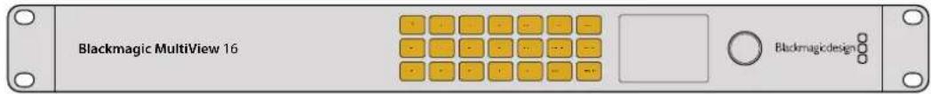
Blackmagic MultiView 16
MultiView 16 is a single rack SDI multi viewer for simultaneously displaying up to 16 different SDI signals in a variety of formats on a single monitor. With Ultra HD support and remote control using the intuitive Videohub software, you get the ultimate monitoring solution for your Blackmagic Videohub routers!
Each of the Blackmagic MultiView 16's SDI inputs has its own loop output so you can feed each signal to other SDI equipment. Two 6G-SDI outputs and two down converted HD-SDI outputs let you connect HD or Ultra HD monitors. The HDMI output switches between HD and Ultra HD based on the format that your connected monitor supports. All SDI connections support auto detection of SD, HD, 3G-SDI and 6G-SDI, reclocking on all SDI outputs, and a reference input for connecting to switchers and other broadcast video equipment.

You can operate Blackmagic MultiView 16 using the built in control panel, or remotely via Ethernet or serial connections if mounted in a rack where you don't have access to the front panel. Third party router controllers can control the unit via Ethernet, or as an RS-422 slave device for router switching.
The multi view output can be switched between different layouts, such as 1x1, 2x2, 3x3, or you can see all your inputs together using 4x4 view. Blackmagic MultiView 16 can even be used to distribute four independent native HD signals in one Ultra HD picture!
Blackmagic MultiView 16 is AC powered.
Using the Control Panel
Blackmagic MultiView 16's control panel provides fast access to settings, sources and views.
LCD and Home Screen
The built in LCD provides a fast and intuitive way to view and adjust your settings. The 'home' screen is the default screen when first powering your Blackmagic MultiView 16 and displays a convenient overview of settings, which includes the following information:
HD video output format
This information is located in the upper left corner and displays the 1080i59.94 or 1080i50 HD format setting via the HD-SDI outputs.
Audio input
This information is located next to the HD-SDI video output format and displays which SDI input is being used to embed audio into the HDMI and SDI multi view output signals.
Multiview layout
This displays the arrangement of your views. You can optimize the display depending on the number of inputs connected.
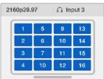
The home screen is the default display on the control panel LCD. If you have adjusted a setting, you can always return to the home screen by pressing the 'menu' button.
Control Buttons
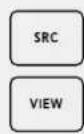
SRC and VIEW
Use the 'src' and 'view' buttons to open the 'source' and 'view' settings. These buttons let you select which input source you want to display on a desired view.
1 Press the 'view' button to open the view screen. The view section on the lower half of the LCD will be active.
2 Press a numbered button on the control panel to select your desired view, or alternatively you can use the rotary knob to scroll through the views. Confirm your setting by pressing the 'set' button.
Press the src button. The source section on the upper half of the LCD will become active.
4 Press a numbered button on the control panel to select your desired input, or alternatively you can use the rotary knob to scroll through your inputs on the LCD. If you have customized your input labels, they will be displayed accordingly in the upper half of the LCD.
5 Press the 'set' button to confirm the setting.

SOLO
You can monitor a view in fullscreen mode by pressing the 'solo' button. With solo enabled, press the number buttons on the control panel to select which view to monitor, or you can use the rotary knob to scroll through your views. Press 'solo' again to return to the multi view layout.

SET
Press the 'set' button to select and confirm settings. When you press the set button to select a menu item, the adjustable setting field will become underlined and both the 'set' and 'menu' buttons will flash. After changing a setting, press the set button again to confirm the change.

MENU
Press the 'menu' button to open the settings screen. After adjusting a setting, you can also press the 'menu' button to return to the home screen.

NUMBERS
The number buttons are used to select your inputs and views for the source and view settings.
The buttons can also be used to select which SDI input you want to use for the 'audio in' setting.
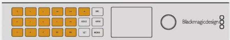
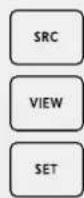
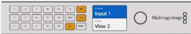
SRC, VIEW and SET
Press the source and view buttons on the control panel to open the source and view settings. To adjust settings, use the number buttons or the rotary knob, then press 'set' to confirm.
The source and view settings screen highlights which setting you are currently adjusting. Any customized input labels will be displayed accordingly.
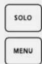
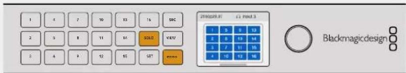
SOLO and MENU
Press the 'solo' button to enter fullscreen mode. Press the 'menu' button to enter the settings page and to return to the home screen.
GPI and Tally Interface
The Blackmagic Design GPI and Tally Interface is a low cost alternative for multi-camera productions where a camera control unit, or CCU, operator needs to switch video from one of several cameras being controlled to a single monitor. It features 8 configurable GPIs and 8 configurable GPOs.
Under certain crosspoint conditions, the GPIs send commands to your Videohub via Ethernet to switch the selected camera to the operator's monitor and the GPOs send a tally signal to your cameras or other equipment.

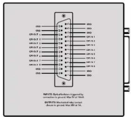
GPI and Tally Interface Pinout diagram of the DB25 connector
Refer to the pinout diagram on the back of the unit when fabricating your custom cable.
For information on how to configure your GPI and Tally Interface using Blackmagic Videohub Setup, refer to the 'Blackmagic Videohub Software' section of this manual.
Blackmagic Videohub Software
Blackmagic software includes three important software applications used to configure and control your Videohub and Videohub hardware panels. Download the Blackmagic Videohub Software from the Blackmagic Support Center at www.blackmagicdesign.com/support
Blackmagic Videohub software includes the following applications:
Blackmagic Videohub Setup. This is an administration utility for changing settings, configuring your Videohub and updating the unit's internal software.
Blackmagic Videohub Hardware Panel Setup. This utility is used to configure Videohub Master Control Pro and Smart Control Pro hardware panels.
Blackmagic Videohub Control. This application is a software control panel that lets you control your Videohub remotely via USB or over an Ethernet network.
Blackmagic Videohub Setup
Using Blackmagic Videohub Setup, you can label the inputs and outputs to identify sources and destinations, plus maximize the results of your Videohub's filtering system when using the shortcut buttons. You can also create macros, map shortcut buttons and more.
The first step is to download and install the Videohub software onto your Mac or Windows PC. The software is freely available at www.blackmagicdesign.com/support
Once installed on your computer, connect your Videohub via USB then go to your applications folder and launch Blackmagic Videohub Setup.
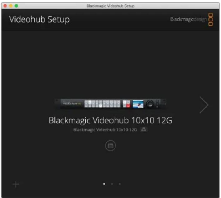
The first screen you will see is the home screen. This is where you can select your Videohub if you have more than one unit connected. Simply click on the left and right arrows to move through the units.
To open your Videohub's settings, click on the settings icon under the image of your Videohub.
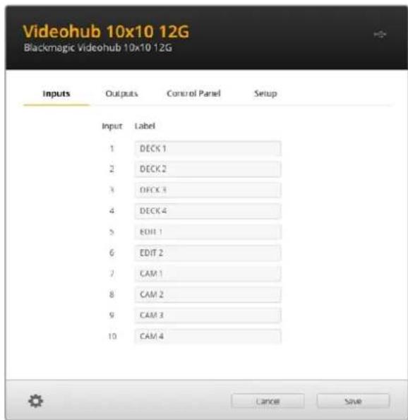
Labeling Inputs and Outputs
The 'inputs' and 'outputs' tab lets you change the labels for all your source inputs and destination outputs.
To label a source and output:
1Click in a source or destination's text field.
2Type a new name. Press the return key on your computer keyboard to move to the next field, or simply click in the next text field to select it.
3 When you have entered all the labels, click save'.
It's important to label them so they match the shortcut button labels on the unit, for example DECK for playback and recording decks, MON for monitor destinations, etc. If you want to change them to something else, you should also change the physical shortcut button labels on the unit to make sure they correspond. You can find information on how to change the pushbutton labels in the 'labeling pushbuttons' section.
TIP Videohub text filtering is case sensitive.
Once you have labeled your source inputs and destination outputs, you can also save them as a label set. This means if you need to change the labels for a new project, you can always reload the previous set you saved earlier.
To save a label set:
1Click on the gear icon at the bottom of the inputs or outputs settings and select 'save label set'.
2Type a name for the label set and choose the save location. Click 'save'.
To load a label set:
1Click on the gear icon at the bottom of the inputs or outputs settings and select 'load label set'.
2 Choose the label set you have previously saved and click 'open'.
NOTE Port labels on an IP Videohub cannot be edited as these labels derive from the connected IP Video devices. The labels are stored on the connected Videohub and are also visible on the other control panels connected to your network.
Setting Outputs to Cut Bus Mode
In the output settings you will notice checkboxes next to each output. These let you set them to cut bus mode. When an output is set to use cut bus mode, it will change the route the moment a source is selected without using the take button to confirm it.
You can select which destinations use cut bus mode individually, or enable and disable cut bus mode on all outputs by clicking 'all on' or 'all off' buttons.
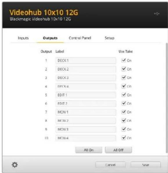
Cut bus mode will switch a route without using the take button
Creating Macros
The control panel tab also lets you create macro buttons and assign their functions.
Click and drag the 'number of macros' slider to the right to add macro buttons and drag left to remove them. As you add macro buttons you will see the buttons in the utility illuminate white.
To assign a macro to a macro button:
1 Click on a white macro button in the 'button mapping' section. You will see a menu appear underneath with rows from A to P. Each row represents a routing action.
2In the 'A' row's 'source' menu, select the input source and then select the destination output.
3Click 'save'.
The macro is now assigned to a macro button.
The macro assigned in steps 1 to 3 assigns a single routing action to the macro button, but you can also add a range of other actions to happen simultaneously when that macro is performed. For example, you may have a project setup that contains a complex sequence of routing changes. In this case, the entire sequence can be assigned to a single macro button. It's very powerful!
To activate a macro, simply press the macro button on the panel and then press 'take' to confirm the switch.
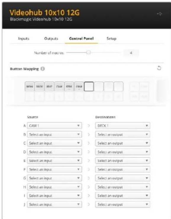
Macros let you perform multiple simultaneous routes
Button Mapping
The labeled shortcut buttons on your Videohub's control panel are used to select groups of equipment when changing routes. For example, if you have 3 HyperDeck sources with their inputs labeled DECK 1, DECK 2 and DECK 3, you can press the DECK shortcut button to reduce the selection to only those 3 sources. The reduced sources can then be selected using the spin knob or by pressing pushbuttons 1, 2, or 3. This is especially helpful when using larger Videohubs with many types of equipment connected.
If you want to create a new shortcut button label, it's important to also change the corresponding physical button label on the unit. Refer to the 'labeling pushbuttons' section for more information.
To map a shortcut button label:
1 Click on a labeled shortcut button and type a label in the text field. It's important to keep the label consistent with the corresponding input and output labels. For example, if your HyperDeck sources are labeled DECK 1, DECK 2, DECK 3, etc, they will be recognized by a shortcut button mapped with the label 'DECK'.
2Click save'.
Refer to the 'shortcut buttons' section for information on how to use mapped shortcut buttons when switching a route.
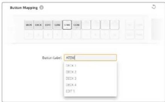
Type a new name for the shortcut button and click 'save'
Setup Settings
The setup settings tab lets you name your Videohub so you can identify it on a network. Simply type in a name and then click on the 'set' button.
To change the language used on your Videohub's LCD, click in the language menu, select your language and click 'save'.
The software version is displayed so you can check it against the latest version on the Blackmagic Design support center at www.blackmagicdesign.com/support
Video Monitoring
When video monitoring is enabled, the LCD will show a preview of the source currently routed to a destination. For example, if you press the destination button and select an output, you will see the source currently routed to that output.
Additionally, you can also check the source video before switching the route. For example, scrolling through the sources using the spin knob lets you visually confirm the desired video feed.
If you want to disable the video preview mode, deselect the 'video monitoring' setting in the 'setup' settings tab. This returns the LCD to the home screen, displaying the standard source and destination text view.
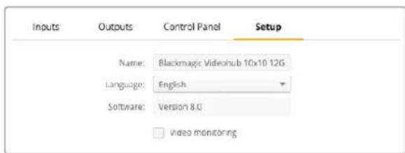
Deselect the 'video monitoring' checkbox to disable the source and destination video preview mode on the LCD
Network
The network settings let you set the unit to use DHCP for automatic network connection, or static IP if you need to manually set an IP address.
The network settings can be changed when your Videohub is connected to a computer via USB.
To help limit the potential for accidental administration changes, Blackmagic Videohub Setup can be set to only allow users to make settings changes via USB. To enable, select 'via USB'.
Network settings are important for controlling your Videohub over a network using Videohub Control software or an external hardware control panel, for example controlling a Universal Videohub 288 using Videohub Master Control Pro. Refer to the 'connecting Videohub to a network' section for more information about network settings.
Reset
The factory reset button deletes all assigned macros and labels and restores the unit to its original factory settings.
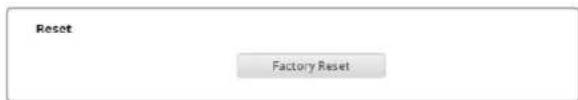
Updating your Videohub
Occasionally, the internal software in your Videohub will need to be updated. Updates to internal software can provide new features, compatibility with new hardware and support for new formats.
Please follow these steps to update your Videohub's internal software:
1Connect your computer to the Videohub's USB 2.0 connector.
2 Launch Blackmagic Videohub Setup and it will automatically display any Videohubs that are connected to your network.
3Select your Videohub by clicking on either the picture or the configuration icon.
4The utility will inform you if an update is required.
5 If an update is required, click the Update button and allow the software to install. Make sure not to unplug the Videohub while the update is in progress.
Click the Close button when the update is finished.

Do not unplug the Videohub while the update is in progress
Blackmagic Videohub Control
Using Blackmagic Videohub Control provides a fast and intuitive way to view and switch between multiple sources and destinations remotely. Videohub Control is easy to use because it operates on a single video output at a time. Selecting a destination or output pushbutton shows which source or input is connected to it by illuminating the source pushbutton. To change the source, simply click on a different source pushbutton. It's that easy!
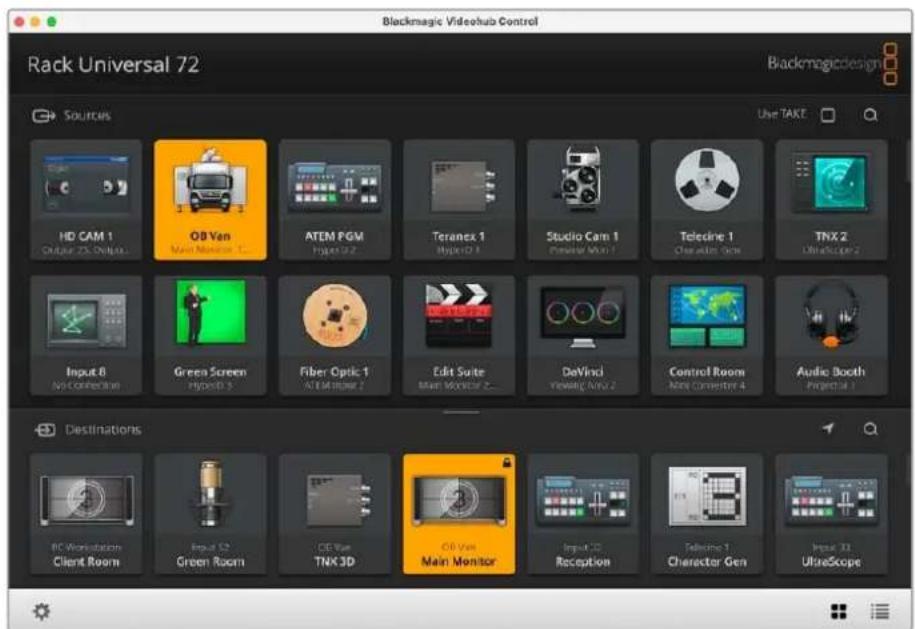
Videohub Control provides an intuitive, icon driven representation of the Videohub connections
Selecting a Videohub
Launch Blackmagic Videohub Control, click on the settings gear icon and choose 'select Videohub'. Click on the Videohub that you wish to control. If you have customized your labels, the names you assigned will appear within the software. All Video hubs on the network, including IP Video hubs, will appear in this list.
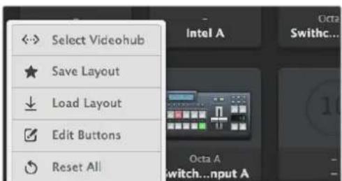
Click on the 'select Videohub' option and then select the Videohub you wish to control
Adding Pushbuttons
Click on the settings gear icon and then select 'edit buttons'. Click on the 'add' button and choose whether to add a source or destination pushbutton. The 'set button' window appears and allows you to set the SDI source or destination, RS-422 deck control and icon for the pushbutton. In most cases, deck control is grouped with the associated SDI connections.
Viewing Routes
In order to see which video source has been routed to a video destination, such as a monitor, press the button in the destinations panel to make the button illuminate. The associated video source button will illuminate in the sources panel, making it immediately obvious which source is connected to the monitor.
Switching Routes
In order to change the video source from a tape deck to a video camera, press a camera pushbutton in the sources panel to immediately illuminate the camera pushbutton and route video to the video monitor. The tape deck button is no longer illuminated and is disconnected from the video monitor.
| Resizing the Interface | Click and drag the bottom right hand corner to proportionally resize the interface to best fit your screen size. Alternatively, drag a window edge to resize either vertically or horizontally. |
| Resizing the Sources and Destinations Areas | Drag the divider bar up and down and use the scroll bars to scroll the respective areas. |
| Switching Views You can switch between pushbutton view and list view by clicking the icons in the bottom right corner. | |
| Using the Dynamic Search | Both the sources and destinations areas contain a search icon, which allows you to search for text dynamically. This is useful if you have many pushbuttons and quickly want to locate a pushbutton with a specific name. Begin by typing the name you wish to search for. As you type each letter, the pushbuttons that are displayed will be dynamically filtered. |
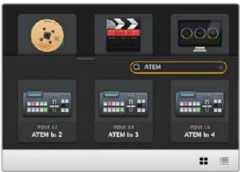
The word 'ATEM' is entered into the destinations search box and the filtered results are displayed
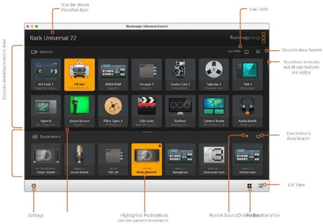
Blackmagic Videohub Control at a Glance
Click and drag the window edges to resize Blackmagic Videohub Control to fit your screen size. Drag the Divider Bar up or down to reveal more or less of the "Sources" and "Destinations" areas and use the Scroll Bars to scroll the areas.
Settings Menu
| Select Videohub | ←→ | Select from a list of Videohubs that are currently connected to your network. |
| Save Layout | ★ | Save customized pushbutton layouts for the different environments in which you use your Videohub. |
| Load Layout | ↓ | Load previously saved pushbutton layouts. |
| Edit Buttons | ☑ | Displays the Edit Buttons for editing the pushbuttons. |
| Reset All | ◎ | Displays all of the inputs and outputs of the connected Videohub and replaces customized icons with the default icon. Source, destination and deck control settings are maintained. |
Edit Buttons
| Add Add a source or | destination | pushbutton. |
| Edit | Allows you to set the SDI source or destination, deck control and the icon for the selected pushbutton. | |
| Lock and Unlock | Lock a destination to avoid accidentally changing the video source which is routed to that destination. If you click on a pushbutton that's locked, the Lock button changes into an Unlock button. Simply click the Unlock button to unlock the destination pushbutton. | |
| Clear | Deletes source, destination and deck control settings as well as the icon for the selected pushbutton. | |
| Remove | Removes the selected pushbutton. | |
| Done | Done | Click the Done button to exit the edit mode. |
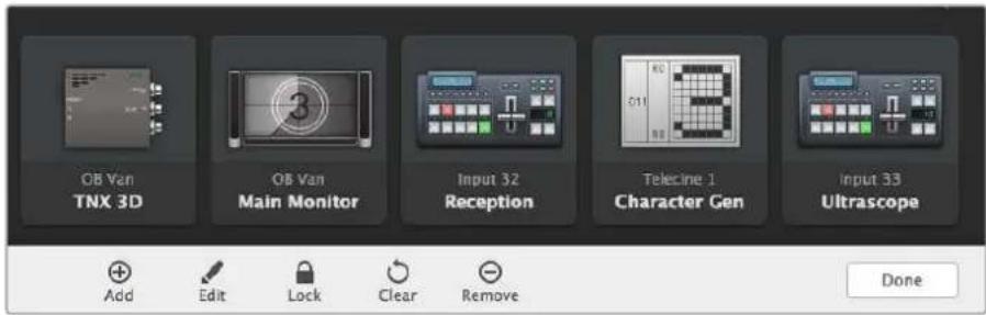
Click 'edit buttons' Buttons to choose a thumbnail image for a source or destination
Using Pushbuttons
| Adding Pushbuttons | Select the Settings button and then select "Edit Buttons". Click on the Add button and choose whether to add a source or destination pushbutton. The Set Button window appears and allows you to set the SDI source or destination, RS-422 deck control and the icon for the pushbutton. In most cases, deck control is grouped with the associated SDI connections, e.g., SDI Input 1 would be associated with the corresponding Remote 1. |
| Editing Pushbuttons | Select "Edit Buttons" and click the pushbutton you wish to edit. Click on the Edit button and modify the source or destination, deck control settings and the icon as required. |
Set Button The Set Button window allows icon selection, source or destination selection and deck control configuration.
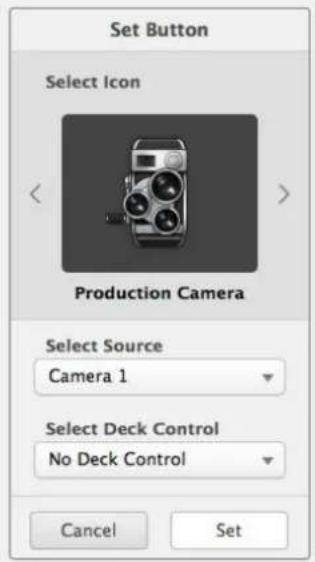
Moving Pushbuttons
Select the Settings button and then select "Edit Buttons". Click and drag the pushbutton to a new position.
Viewing and Switching Routes
Viewing Routes In order to see which video source has been routed to a video destination, such as a monitor, press the button in the destinations panel to make the button illuminate. The associated video source button will illuminate in the sources panel, making it immediately obvious which source is connected to the monitor.
Reveal Source If you select a destination but the source is currently positioned offscreen, clicking the Reveal Source button will scroll the Sources area to display the source pushbutton.
Switching Routes Select the destination icon followed by the source icon.
Use TAKE Confirmation before Switching Routes
You may wish to enable the 'use take' feature to help prevent unintentional changes to video routes. Once enabled, any attempt to change a video route using a pushbutton will cause a red 'take' button to appear. Click the button to confirm or click the current source or destination pushbutton to cancel.
Locking and Unlocking Routes
Locking a destination will avoid accidentally changing the video source which is routed to that destination. To lock a route, select the destination pushbutton and double click. A padlock icon will appear in the top-right corner of the destination pushbutton and will prevent anyone else from using the destination device until it is unlocked from your computer. Locking a destination still leaves the associated video source available for routing to multiple destinations simultaneously.
Double click the pushbutton to unlock the destination.
You can also lock one or multiple destinations via the edit buttons page. Shift click the destination pushbuttons you wish to lock and click the lock button. If you select a mixture of locked and unlocked pushbuttons, you will have the option to lock the unlocked pushbuttons.
Locking a route between an input and an output also locks the RS-422 deck control connection between the two devices to avoid other users accidentally seizing the deck control belonging to the video source. The RS-422 connection between the video source and video destination will remain locked until the destination pushbutton is unlocked.
TIP To toggle the lock status of a destination, simply double click the destination pushbutton.
A black padlock icon with a curved line above will appear on any destination pushbuttons locked by other Videohub devices. The video destination devices will not be available to you until the destination pushbuttons have been unlocked from the other users' computers and iPads.
If you need to unlock a route set by another user, launch Videohub Setup, select the Outputs tab and click the destination's lock icon.
NOTE It is important to note which routing level is selected, as it will affect the locking of routes. Universal Videohub consists of an SDI video level and an RS-422 deck control level. These levels can be switched together or can be separated for individual switching.
If you have selected SDI 422 on the level controls, it will lock both ports, however, if you select SDI or RS422 it will only lock the selected port. When the RS-422 port is locked you can still switch to SDI video, and when the SDI port is locked you can still switch to RS-422. This means that you can still route video signals even if the RS-422 port is locked, and still have deck control even if the SDI port is locked.
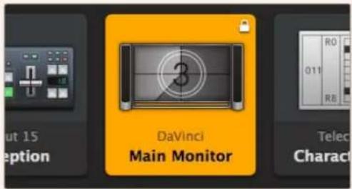
Locally locked destinations display a white padlock icon
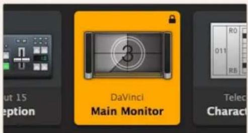
Remotely locked destinations display a black padlock icon
Serial Control Settings
Third party router controllers can control Videohub with RS-422 serial connections.
If controlling Videohub via RS-422, set the 'Leitch protocol' switch to:
- 'Leitch client' if the Videohub is to act as a client of a connected control panel and to listen and respond to the control panel button presses.
- 'Leitch server' if the Videohub is to be controlled from an automation system or third party router control system.
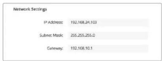
The Videohub Server Configuration options will become active when a Videohub is connected via USB
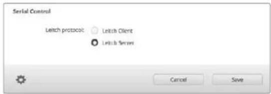
Select either Client or Server when using RS-422 serial control
Touchscreen Computers
Pushbutton View is designed to be easy to use and look beautiful on a large, touchscreen display. Dedicating a touchscreen computer to the Pushbutton View within the Videohub Control software makes it incredibly easy for users to switch connections between multiple SDI devices without having to see every connected device all of the time.
Using a touchscreen computer provides the fastest way to switch connections which is perfect for a master control room. Both desktop and laptop touchscreen computers can be used.
While touchscreens are perfect for rapidly selecting and routing inputs and outputs, they can be cumbersome for configuring pushbuttons. The width of a human fingertip is much wider than a mouse pointer and is less accurate when tapping on menu options and small icons.
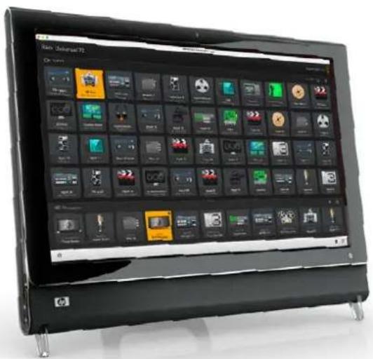
For this reason, we recommend configuring the pushbuttons with a mouse. Once the Videohub pushbuttons have been configured, it will be easy to use a finger to select and route, inputs and outputs, by tapping on Videohub pushbuttons.
Touchscreens work a little differently to a computer mouse but provide the fastest and easiest way to work with the Videohub Control interface and so are highly recommended. When using a touchscreen computer, you can enable the Use Take option to help avoid unintentional routing changes.
Apple iPad
The Videohub Pushbutton controller interface looks stunning on the high resolution Apple iPad display. Aside from looking great, it also provides the convenience of portable router control anywhere in your facility or even over the Internet via a wireless or cellular connection! If you are already familiar with the Videohub Pushbutton interface on a computer, then there is almost nothing new you need to learn and you'll only notice slight differences between computer mouse control and touchscreen control on the iPad. For information on how to download and install the application, refer to 'installing the Videohub Software on iPad' immediately after this section.
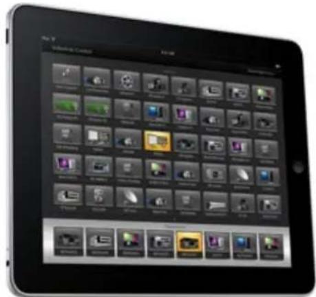
Up to 40 sources and 8 destinations can be displayed in a single Videohub Pushbutton screen on the iPad. Even more sources and destinations can be displayed by flicking the iPad left or right, or tapping to the left or right of the row of dots, to move through multiple Pushbutton screens.
The initial Pushbutton interface
Upon launching the Videohub app on your iPad for the first time, all pushbuttons initially show the generic BNC connector icon, which you can then replace from a selection of icons. If the connections have not yet been labeled, then the source pushbuttons will appear as Input 1 to Input 40 and the destination pushbuttons will appear as Output 1 to Output 8.
If the connections have already been labeled, their names will appear under each of the respective pushbuttons in place of the connector numbers.
Configuring Videohub Pushbuttons on the iPad
Configuring Videohub Pushbuttons on the iPad is easy. Press and hold any Videohub pushbutton to open the Videohub Button Setup window. This window allows you to set the SDI input or output connection, RS-422 deck control and the icon for the pushbutton.
The Clear button will delete all settings for the pushbutton. In most cases, deck control is grouped with the associated SDI connections, meaning an SDI connection named Input 1 would usually be associated with the corresponding Remote 1.
The bottom right source button is reserved by the Videohub app itself and cannot be configured. This is because if a destination pushbutton is connected to a source that does not appear in the sources panel, the source will automatically appear in the bottom right pushbutton.
When configuring pushbuttons, only select a deck control connection for those devices that have RS-422 deck control. It makes no sense to assign a deck control connection to a video monitor or camera.
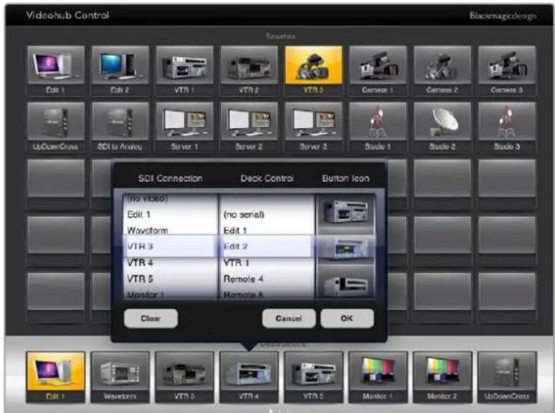
The Videohub Button Setup window allows you to set the SDI input or output connection, RS-422 deck control and the icon for the pushbutton
While all icons are available to any pushbutton, it doesn't make sense to choose the icon of a video monitor or transmitter for a source pushbutton unless the source device happens to have a loop through output.
You may choose to show a particular source or destination pushbutton several times within the one Pushbutton screen or on multiple Pushbutton screens. If a destination pushbutton is routed from a source that appears multiple times in the Sources panel, selecting the destination pushbutton will illuminate all instances of the source pushbutton, regardless of how deck control has been configured for each source pushbutton. Similarly if multiple instances of an output pushbutton appear in the Destinations panel, they will illuminate together when any one has been selected.
Viewing and Changing Routes
In order to see which video source has been routed to a particular destination, such as a monitor, press the monitor's pushbutton in the destinations panel. The monitor button and the associated video source button will simultaneously illuminate, making it immediately obvious which video source is connected to the video monitor, e.g., a HyperDeck Studio HD Pro.
In order to change the video source from a HyperDeck Studio HD Pro to a video camera, press a camera pushbutton in the sources panel to immediately illuminate the camera pushbutton and route video to the video monitor. The HyperDeck Studio HD Pro pushbutton will no longer be illuminated and will be disconnected from the video monitor.
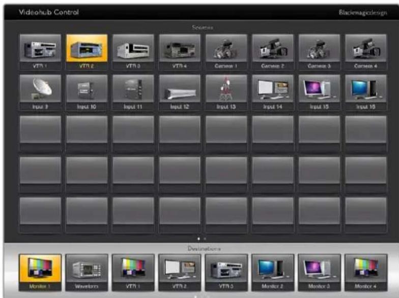
In order to see which video source has been routed to a video destination, tap a destination button and the associated video source button will illuminate
Locking and Unlocking Routes
Locking a destination avoids accidental changes of the video source being routed to that destination. To lock a route between an input and an output, double-tap the destination pushbutton. A yellow padlock icon will appear in the top left corner of the destination pushbutton and will prevent anyone else from using the destination device until it is unlocked from your iPad. Double tap the destination pushbutton again to unlock. Locking a destination still leaves the associated video source available for routing to multiple destinations simultaneously.
Locking a route between an input and an output also locks the RS-422 deck control connection between the two devices. This is to avoid other users accidentally seizing the deck control belonging to the video source.
The RS-422 connection between the video source and video destination will remain locked until the destination pushbutton is unlocked.
A gray padlock icon will appear on any destination pushbuttons that other users have locked. The video destination devices will not be available to you until the destination pushbuttons have been unlocked from the other users' computers and iPads.
If you encounter a gray padlock icon and do not know who locked the video device you can override the lock using the Videohub software on a Mac or Windows computer. When a route is unlocked, the padlock icon will disappear.
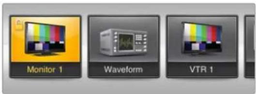
A yellow padlock icon will appear in the top-left corner of the destination pushbutton and will prevent anyone else from using the destination device until it is unlocked from your iPad. A gray padlock icon will appear on any destination pushbuttons that other users have locked.
Installing the Videohub Software on iPad
The Videohub software for iPad can be downloaded using your Apple ID account.
To download the Videohub iPad software through your iPad:
Tap the 'app store' icon.
2Tap the 'search' field at the top of the screen and enter 'Videohub'.
3Tap on the 'get' button next to the 'Blackmagic Videohub app' icon and tap 'install'.
Setting up the IP address in Videohub for iPad:
Tap the 'settings' icon.
2In the 'apps' section, select 'Videohub' and enter your Videohub IP address in the 'Videohub IP address' field.
3 You can now start using your Videohub software by tapping on the Videohub icon on the 'home' screen.
For more information on controlling your Videohub using iPad, see the 'Apple iPad' section in this manual.
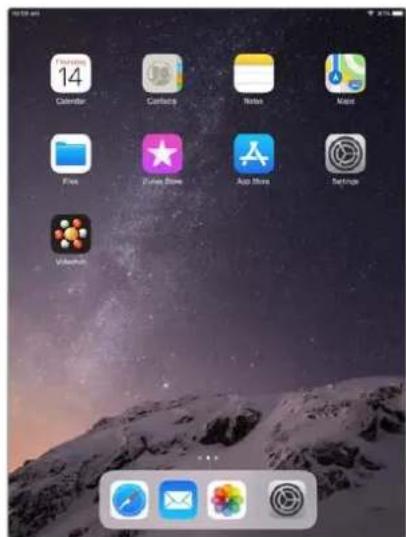
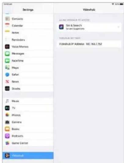
Videohub settings on iPad
Controlling Blackmagic MultiView 16
Blackmagic MultiView 16 can also be controlled using Videohub Control software. Blackmagic Multiview 16 is a single rack SDI monitoring solution capable of simultaneously displaying up to 16 Ultra HD, HD and SD SDI signals in a variety of formats on a single monitor. With Videohub Control you get the ability to route Blackmagic MultiView 16's multi view sources and views, and arrange them on a display the way you want, so is the perfect monitoring choice for your Videohub router workflow.
Up to 16 video signals can be displayed using the maximum 4x4 grid, or you can select 3x3, 2x2, or view each input in full screen mode by selecting solo. When connected to an Ultra HD monitor, Blackmagic MultiView 16 can even display four HD signals in their native 1080 HD resolution.
Connecting Blackmagic MultiView 16 to Videohub Control Software
Ensure Blackmagic MultiView 16 has the latest internal software installed and you are running the latest version of Videohub Control. You can download the latest updates from the Blackmagic Design support center at: www.blackmagicdesign.com/support
1Power your Blackmagic MultiView 16.
2Plug Blackmagic MultiView 16 into your computer via Ethernet.
3Launch Blackmagic Videohub Control.
4Click on the 'select a Videohub' button on the Videohub Control home page and select your Blackmagic MultiView 16 from the list.
Controlling your Blackmagic MultiView 16 using Videohub Control software is an easy and convenient way to change sources and views, and arrange your view displays remotely, while monitoring multiple inputs at the highest video resolution available.
If you can't see your Blackmagic MultiView 16 in the list of Video hubs available, you may need to configure the IP address for your network.
For more information, refer to 'Configuring Network Settings on Blackmagic MultiView 16' below.
Configuring Network Settings on Blackmagic MultiView 16
Use Blackmagic MultiView 16's integrated control panel and LCD to set the IP address and network settings. Once these settings are set correctly, your Blackmagic MultiView 16 will be visible to other computers and hardware panels. These devices can then control the unit remotely and make routing changes using the Blackmagic Videohub Control software.
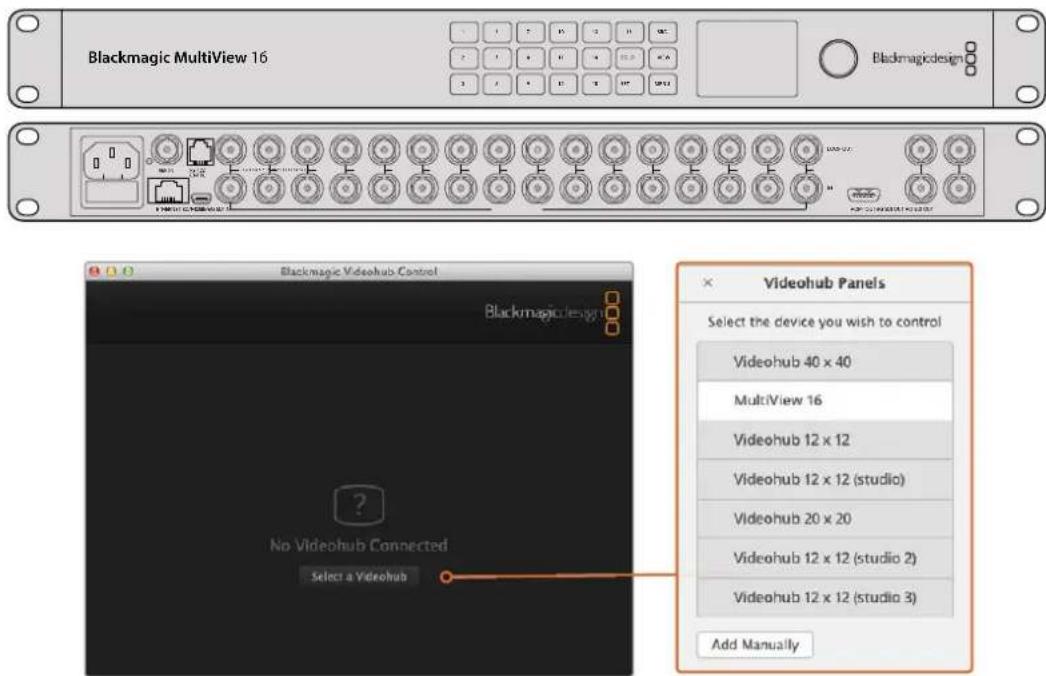
Connect to Blackmagic Videohub Control software by clicking on the 'select a Videohub' button, then select your Blackmagic MultiView 16 from the list
To configure your network settings:
Press the 'menu' button and turn the rotary knob to highlight the 'networking' tab.
2 Press the 'set' button to enter the 'network settings' page.
3 Turn the rotary knob to select the 'IP address' tab.
4 Press the 'set' button to highlight the first field of the IP address. You can use either the rotary knob or numbered pushbuttons to enter values.
5 Press 'set' to confirm the first field of the IP address, then repeat the above step for the next three fields until you have set the desired IP address. If you need to assign the Subnet and Gateway address, they can be set using the same method.
6 Press the 'menu' button twice to return to the home screen.
For more information on how to use Blackmagic MultiView 16 with Blackmagic Videohub Control software, refer to the Blackmagic MultiView instruction manual. You can find the latest manual and product updates at the Blackmagic Design support center at: www.blackmagicdesign.com/support
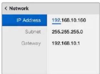
Use the rotary knob or the number buttons on Blackmagic MultiView 16's control panel to assign values to your network settings
Videohub Hardware Panel Setup
When you launch Blackmagic Videohub Hardware Panel Setup, any Videohub control panels discovered on the network will be listed in the Videohub Control Panels pane next to an Ethernet network icon. If several Videohub control panels are listed, but you don't know which one is which, select one of them and then press Identify. This will cause all the buttons of the selected Videohub control panel to flash white.
Select the desired Videohub control panel and you will be able to change its name and control settings. Network settings will remain grayed out and can only be changed via USB.
If the desired Videohub control panel is not found on the network, the unit might not have received an IP address via DHCP. To manually configure the unit with appropriate network settings:
1Connect the Videohub control panel to your computer via a USB 2.0 cable.
2Launch Blackmagic Videohub Hardware Panel Setup. If the utility prompts you to update the software, follow the prompts to complete the update.
3The USB connected panel will be automatically selected in the Videohub Control Panels pane and will display a USB icon next to its name. You can change all name, network and control settings for the USB connected unit. When you are finished, the USB cable can be removed.
If your Videohub control panel is selected in the control utility, the pushbuttons on the unit will light up to match what is displayed in the software interface.
Network Settings
Each Videohub control panel requires an IP address to communicate with Videohub via your IP network.
When configuring a Videohub control panel via USB, you can choose DHCP or Static IP. DHCP automatically obtains all the network settings for your Videohub control panel and is the easier choice.
If you decide to use a static IP address, please ask your system administrator for a spare IP address to avoid creating a conflict on your network. You will then need to complete the IP address, subnet mask and gateway details for your Videohub control panel. You must use a static IP address if you are connecting directly to a Videohub without using a network switch.
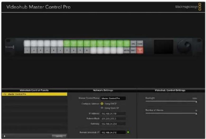
The Blackmagic Videohub Hardware Panel Setup automatically searches your network for any Videohub control panels
You will also need to complete the IP details for the remote Videohub that you wish to control with your Videohub control panel. The remote Videohub is the Videohub Server. This could refer to a Videohub Server computer or an integrated Videohub Server onboard a Videohub model such as Smart Videohub 20x20.

Any Ethernet or USB connected control units will be listed in the Videohub Control Panels pane with a corresponding icon

Blackmagic Videohub Hardware Panel Setup network settings
If you are setting up hardware panel control for an IP Videohub, enter the host computer's IP address in the 'remote Videohub IP' setting field. The Videohub server shares the same IP address with the host computer.
Add Videohub Control
If you already know the IP address of a Videohub control panel but it hasn't automatically appeared in the Videohub Control Panels pane, you can add the unit manually.
1 Press the + (add device) button at the bottom of the Videohub Control Panels pane.
2 Type in the IP address of the Videohub Control Panel and press OK.
3 The Videohub Control Panel will appear in the list with any other devices that are connected to the Videohub.
If the Blackmagic Videohub Hardware Panel Setup does not find a Videohub control panel at the specified address, you can use the Utility to manually add a Videohub control panel when connected via Ethernet or USB.

You can manually add a Videohub control panel, by IP address, to the list of Videohub Control Panels
Load/Save Settings
You can apply settings from an already configured Videohub control panel to other units.
Once you have set up your Videohub Control Panel's settings, choose File>Save Settings. This is useful if you want to set up several units the same way, or keep a back up of your settings.
After loading preconfigured settings on another control panel, you only need to update network settings, including the control panel name.
Configuring Videohub Master Control Pro
Videohub Hardware Panel Setup software lets you customize the hardware features of each Videohub control panel.
Backlight
Adjust the backlight slider as desired to vary the brightness of all backlit buttons.
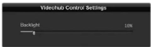
You can adjust the brightness of all backlit buttons in Videohub Master Control
Creating Button Labels
21 of the buttons can be labeled within the control utility to provide fast selection of common equipment types such as cameras, VTRs and monitors. Any of these 21 buttons can also be configured as macro buttons.
If you haven't done so already, you should standardize the port labels on your Videohub router before labeling any buttons on your Videohub control unit.
Please refer to the 'labeling pushbuttons' section for detailed information on customizing your labels.
You are now ready to label the Videohub Master Control Pro buttons.
1Launch the Videohub Hardware Panel Setup and select your Videohub Master Control Pro from the Panels pane.
2 Click one of the 21 buttons in the picture of the panel. Enter a text label so it partially matches the labels of SDI and deck control ports that you previously entered for your router.
3Click OK and continue labeling the other buttons as desired.
4 You can immediately test the buttons as you program them and verify the SDI routes are valid.
Refer to the 'labeling pushbuttons' section for instructions on how to label the physical pushbuttons.
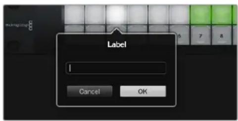
Click on the desired button to edit its label
Configuring Videohub Smart Control Pro
Videohub Hardware Panel Setup lets you customize the hardware features of each Videohub control panel.
Number of Destinations
Videohub Smart Control can be configured as a cut bus controller or as an XY controller. When configured as a cut bus controller, every button represents an SDI source and there is only one destination.
When configured as an XY controller, Videohub Smart Control Pro can work with up to 24 destinations. The source buttons will illuminate white and the destination buttons will illuminate gold. Use this configuration if you don't intend to dedicate a Videohub Smart Control Pro unit to each destination device.
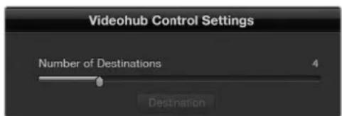
Videohub Smart Control Pro configured with multiple destinations
Cut Bus Configuration
1Drag the Number of Destinations slider to 1.
2Click on the Destination button. In the Router SDI Out A field, enter the number of the Videohub output port to which the destination device is connected. If your destination device requires dual link SDI, you will need to enter an output port number in the Router SDI Out A & B fields. For quad link SDI, you will need to enter numbers in all four 'out' fields. There is a Router Remote field if your Videohub is also routing RS-422 deck control to the destination device.
3 Click OK to confirm. All the buttons will become white, indicating that they are all sources.
4Click on each white button in the software interface to configure the source buttons.
5In the RouterSDI In A field, enter the number of the Videohub input port to which the source device is connected. For dual link SDI destinations you will need to enter port numbers for fields A and B, or fields A through D for quad link SDI. There is a Router Remote field if your Videohub is also routing RS-422 deck control from the source device.
6Click OK to confirm.
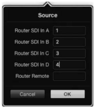
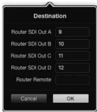
Add a port number for all SDI fields when using quad link SDI destinations
XY Controller Configuration
1Drag the Number of Destinations slider to the desired number.
2 You can now configure the destination buttons by clicking on each gold button in the software interface. In the Router SDI Out A field, enter the number of the Videohub output port to which the destination device is connected. For dual link SDI destinations you will need to enter port numbers for fields A and B, or fields A through D for quad link SDI. There is also a Router Remote field if your Videohub is also routing RS-422 deck control to the destination device.
3Click OK to confirm. If you increase the number of destination buttons, there will be a matching decrease in the number of available source buttons.
4Click on each white button in the software interface to configure the source buttons.
5In the Router SDI In A field, enter the number of the Videohub input port to which the source device is connected. For dual link SDI destinations you will need to enter port numbers for fields A and B, or fields A through D for quad link SDI. There is also a Router Remote field if your Videohub is also routing RS-422 deck control from the source device.
6Click OK to confirm.
Number of Macros
Macros allow you to make up to 16 crosspoint routing changes simultaneously with a single button press.
1Drag the Number of Macros slider to enable up to 10 macro buttons. As you increase the number of macro buttons, there will be a matching decrease in the number of available source buttons.
2Click a green macro button to reveal the corresponding Macro window and enter up to 16 pairs of sources and destinations.
3When finished, click OK to save the routes and close the window.
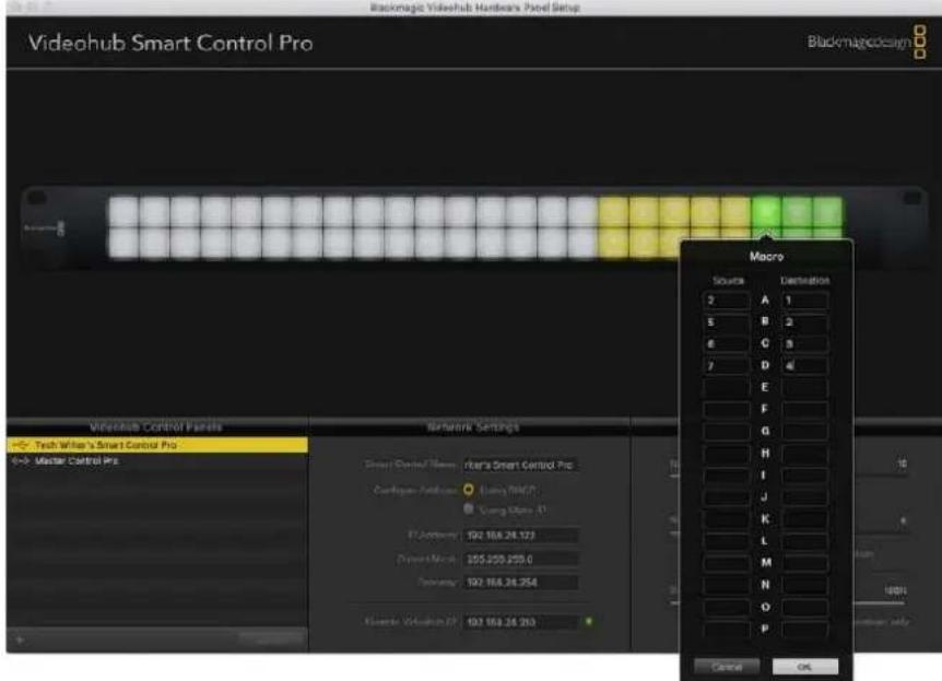
Up to 16 crosspoint routes can be changed by a single macro
Take Button
When the Enable Take Button checkbox is active, the lower right button on the control interface turns red. Use this if you want a confirmation option to come up before your route change takes place. Press the red take button to confirm your route change. The take button can be used with both Cut-Bus and XY controller configurations and can also be used with macros.
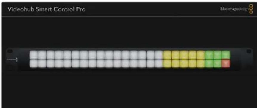
The Take button illuminates red in the lower right corner
Backlight
Adjust the backlight slider to vary the brightness of the backlit buttons as desired. Enable Backlight Destinations Only if you wish to disable the backlighting of the white source buttons.
Configuring GPIs
The GPI and Tally Interface has 8 GPIs that provide crosspoint switching. In the example on the left, if GPI 1 detects a contact closure it will switch Input 12 on your Videohub to Output 1. This means when you switch the joystick control on your CCU, video going to Input 12 of your Videohub will be previewed on your monitor.
The crosspoints can be configured in the Videohub Hardware Panel Setup simply by clicking inside the Input and Output fields on the diagram and typing in the Input or Output number.
The Videohub Control Settings pane offers two ways to preview the output from your Videohub.
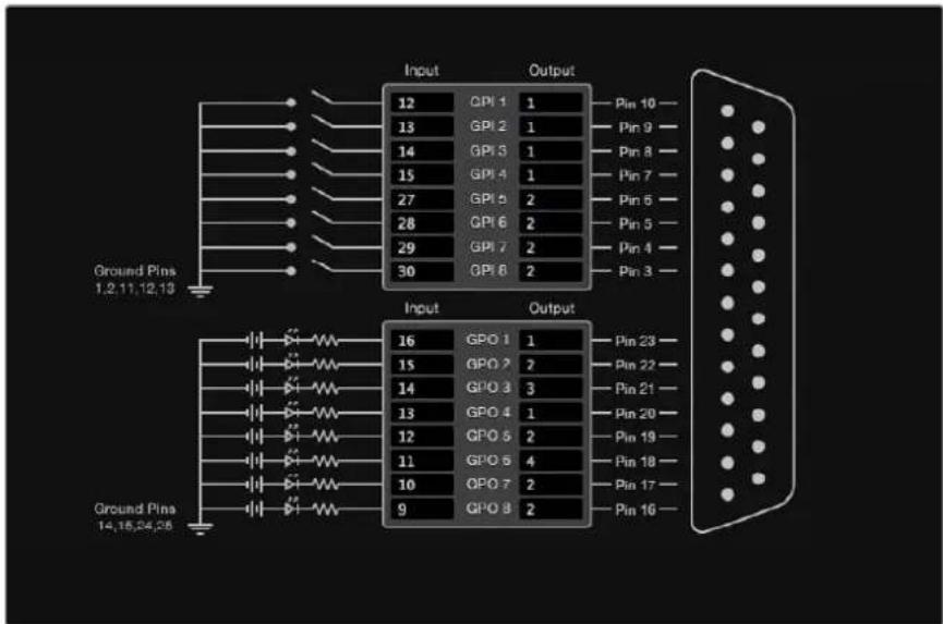
Click inside the diagram to change inputs and outputs for GPI crosspoint switching and Tally
Latch Video
If you want the output to stay as selected, choose Latch Video. This means you can press the switch once on your CCU and the input from the selected crosspoint will stay on your monitor until another crosspoint is selected.
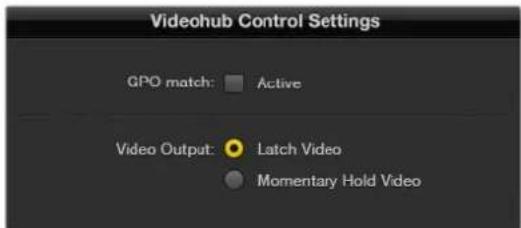
Select Latch Video if you want your preview to hold until another crosspoint is selected. Choose Momentary Hold Video if you want your preview to revert back to the previous crosspoint when you release the control switch.
Momentary Hold Video
Select this option if you want the output to return to the previous input after you let go of the switch or joystick control on your CCU. For example, when you press and hold your switch, Input 13 might be previewed, but will return to displaying Input 12 on your monitor once you release the switch.
Configuring Tally
Tally is usually a lamp on the front of a camera to indicate that it is on air, but it's a useful visual indicator and can be used on any equipment to indicate activity and doesn't have to be used specifically with cameras.
The GPI and Tally Interface has 8 configurable GPOs, which send a tally signal to your cameras or other devices under certain crosspoint conditions. In the example on the left, GPO 1 is configured so that when Input 16 on the Videohub is routed to Output 1, GPO 1 will be activated.
The crosspoints can be configured in Videohub Hardware Panel Setup simply by clicking inside the Input and Output fields on the diagram.
GPO Match
Enable the GPO match checkbox to replicate the configuration of your crosspoints from GPIs to GPOs. This can be useful if you want to see a tally light activate when changing routes for your GPIs.
When this checkbox is enabled, the GPO half of the diagram will be grayed out and cannot be edited until the GPO match checkbox is disabled.

Enable the GPO match checkbox to replicate the crosspoint configuration of your GPIs
Daisy Chaining Multiple GPI and Tally Interfaces
The GPI and Tally Interface supports 8 GPUs and 8 GPOs at a time, which should be enough for most live television situations. However, if you have more than 8 cameras then you may want to daisy chain a second or third GPI and Tally Interface.
The GPI and Tally Interface has two Ethernet ports so that you can connect one port to a Videohub and use the other port to link other GPI and Tally Interfaces together.
1Connect power to the first GPI and Tally Interface.
2Connect a standard RJ45 Ethernet cable from your Videohub or network to the Ethernet IN port on the GPI and Tally Interface.
3Connect power to the second GPI and Tally Interface.
4Connect a standard RJ45 Ethernet cable from the Ethernet OUT of the first GPI and Tally Interface to the Ethernet IN port on the second GPI and Tally Interface.
This can be repeated for as many GPI and Tally Interfaces as you need as long as power is supplied to all units in the chain.
Sometimes it can get confusing to know which GPI and Tally Interface you are working with when you have several connected. Select the GPI and Tally Interface in the Videohub Control Panels pane and click the Identify button. The LED next to the Ethernet IN port on the selected device will light up.
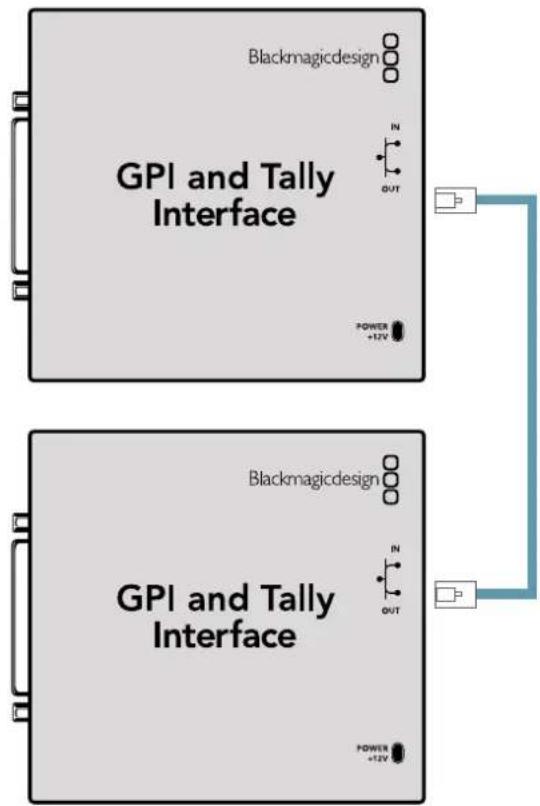
Daisy chain multiple GPI and Tally Interfaces using Ethernet. Power must be supplied to each individual unit in the chain.
Adding a GPI and Tally Interface Over a Network
You may want to configure a second GPI and Tally Interface but it may be in another location and only accessible over a network. You can add it to your list manually by entering its IP address into Videohub Hardware Panel Setup.
If you do not know the IP address of the GPI and Tally Interface you want to add, connect it to a computer with USB, open Videohub Hardware Panel Setup and note down the IP address in the Network Settings tab.
If you do not have access to the unit because it is in another location, you can find it on the network using the Bonjour browser. This application will show you all the devices on your network and will give you the IP address of the GPI and Tally Interface you wish to add.
1Press the ^+ (add device) button at the bottom of the Videohub Control Panels pane.
2Type in the IP address of the GPI and Tally Interface and press OK.
3 The second GPI and Tally Interface will appear in the list with any other devices that are connected to the Videohub.
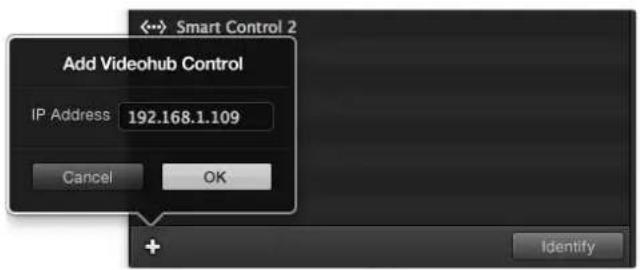
Press the + (add device) button and enter the IP address of a GPI and Tally Device you want to add. Press the Identify button to activate the LED on a selected GPI and Tally Interface.
Setting up the GPI and Tally Interface
The GPI and Tally Interface is configured using the Videohub Hardware Panel Setup. Before you can use the GPI and Tally Interface, you may need to install the latest version of the software.
1Connect the power adapter to the GPI and Tally Interface.
2Connect the GPI and Tally Interface to your computer with a USB Type A to B cable.
3Open the software and it will detect whether your GPI and Tally Interface has been configured for a Videohub before. If it has the software will open without any need for changes. Otherwise a message will tell you your GPI and Tally Interface has been configured for use with an ATEM Switcher and will need to be reconfigured for use with Videohub. Click Yes. After a few moments the GPI and Tally Interface will be reconfigured as a Videohub client.
Configuring the GPI and Tally Interface
If your Videohub does not have an Ethernet port, or if it is only accessible over a network:
1Connect a USB type A to B cable from your GPI and Tally Interface to your computer.
2 Connect an Ethernet cable from the Ethernet IN port on your GPI and Tally Interface to your Ethernet switcher.
3Open Videohub Hardware Panel Setup.
4 You should see your GPI and Tally Interface with a USB icon next to it in the Videohub Control Panels pane. Give your GPI and Tally Interface a unique name so it can be easily recognized. To do so, click inside the GPI and Tally Name field and type a name.
5 Check the option to configure your IP address as 'using DHCP' or 'static IP'. Depending on your setup, you may choose either so it's probably a good idea to check with your network administrator to see which is the better option.
In the Remote Videohub IP field, enter the IP address of the Videohub you want to connect to. A red light next to the field will turn green and the LED on the GPI and Tally interface will illuminate when a connection has been established.
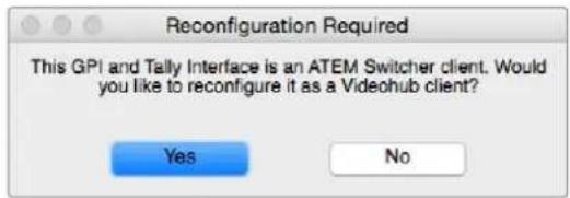
You will need to reconfigure your GPI and Tally Interface to work with Vidcohub

GPI and Tally Interface connected via USB
If you do not know the IP address of your Videohub:
1Connect the Videohub to your computer via USB.
2Launch the Videohub software and click on Videohub Server Preferences.
3Note down the IP address in the Remote Videohub IP address field.
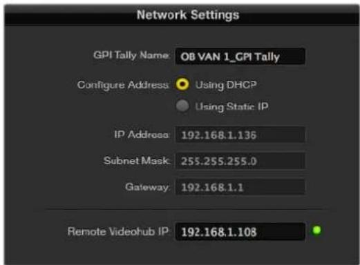
Enter a GPI and Tally Name and the IP address of the Videohub you want to connect to.
Developer Information
Blackmagic Videohub Ethernet Protocol v2.3
Summary
The Blackmagic Videohub Ethernet Protocol is a text based protocol that is accessed by connecting to TCP port 9990 on a Videohub Server. Integrated Videohub Servers and Videohub Server computers are supported by the protocol.
The Videohub Server sends information in blocks which each have an identifying header in all-caps, followed by a full-colon. A block spans multiple lines and is terminated by a blank line. Each line in the protocol is terminated by a newline character.
Upon connection, the Videohub Server sends a complete dump of the state of the device. After the initial status dump, status updates are sent every time the Videohub status changes.
To be resilient to future protocol changes, clients should ignore blocks they do not recognize, up to the trailing blank line. Within existing blocks, clients should ignore lines they do not recognize.
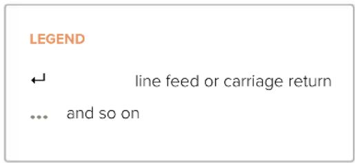
Version 2.3 of the Blackmagic Videohub Ethernet Protocol was released with Videohub 4.9.1 software.
Protocol Preamble
The first block sent by the Videohub Server is always the protocol preamble:
PROTOCOL PREAMBLE:
Version: 2.3
The version field indicates the protocol version. When the protocol is changed in a compatible way, the minor version number will be updated. If incompatible changes are made, the major version number will be updated.
Device Information
The next block contains general information about the connected Videohub device. If a device is connected, the Videohub Server will report the attributes of the Videohub:
VIDEOHUB DEVICE:
Device present: true
Model name: Blackmagic Smart Videohub
Video inputs: 16
Video processing units: 0
Video outputs: 16
Video monitoring outputs: 0
Serial ports: 0
This example is for the Smart Videohub which is a 16x16 router.
If the Videohub Server has no device connected, the block will simply be:
VIDEOHUB DEVICE:
Device present: false
If a device is present, but has an incompatible firmware, the status reported will be:
VIDEOHUB DEVICE:
Device present: needs update
In the last two situations, no further information will be sent, unless the situation is rectified.
If the Videohub Server detects a new Videohub attached, it will resend all blocks except the protocol preamble to indicate the device has changed, and allow the client to update its cache of server state.
Initial Status Dump
The next four blocks enumerate the labels assigned to the input, output, monitoring and serial ports.
Videohubs that do not have monitoring or serial ports do not send the corresponding blocks.
INPUT LABELS:
0 VTR 1
1 VTR 2
咖啡
OUTPUT LABELS:
0 Output feed 1
1 Output feed 2
特此公告。
←
MONITORING OUTPUT LABELS:
0 Monitor feed 1
1 Monitor feed 2
华中特
←
SERIAL PORT LABELS:
0 Deck 1
1 Deck 2
NOTE Ports are always numbered starting at zero in the protocol which matches port one on the chassis.
The next three blocks describe the routing of the output, monitoring and serial ports.
VIDEO OUTPUT ROUTING:
0 5
1 3
...
< VIDEO MONITORING OUTPUT ROUTING:
0 7
1 8
...
< SERIAL PORT ROUTING:
0 12
1 11
...
Videohubs with processing units (only the Workgroup Videohub) send an extra routing block:
PROCESSING UNIT ROUTING:
0 5
1 3
…
Videohubs with frame buffers (only the Workgroup Videohub) send two extra blocks:
FRAME LABELS:
0 Frame one
1 Frame two
...
<1>
FRAME BUFFER ROUTING:
0 7
1 8
...
The next three blocks describe the locking status of the output, monitoring and serial ports. Each port has a lock status of "O" for ports that are owned by the current client (i.e., locked from the same IP address), "L" for ports that are locked from a different client, or "U" for unlocked. Note that Video hubs that do not have monitoring ports or serial ports do not send the corresponding blocks.
Videohubs with processing units (only the Workgroup Videohub) send an extra lock block:
PROCESSING UNIT LOCKS:
0 U
1 U
...
Videohubs with frame buffers (only the Workgroup Videohub) send an extra lock block:
FRAME BUFFER LOCKS:
0 U
1 U
...
Video hubs with serial ports next send a block which describes the direction of each serial port. Each port has a direction of either "control" for the "In (Workstation)" setting, "slave" for "Out (Deck)", or "auto" for "Automatic".
SERIAL PORT DIRECTIONS:
0 control
1 slave
2 auto
...
Video hubs with pluggable cards (only Universal Video hubs) send three more blocks that describe the hardware status of the ports. Missing video or serial ports have a status of "None"; input and output video ports will be "BNC" or "Optical" if they are present; serial ports will be "RS422" if they are present.
VIDEO INPUT STATUS:
0 BNC
1 BNC
…
VIDEO OUTPUT STATUS:
0 BNC
1 BNC
…
SERIAL PORT STATUS:
0 RS422
1 RS422
…
Status Updates
When any route, label, or lock is changed on the Videohub Server by any client, the Videohub Server resends the applicable status block, containing only the items that have changed. For example, if serial port 6 has been unlocked, the following block will be sent:
SERIAL PORT LOCKS:
5 U
If multiple items are changed, multiple items may be present in the update:
OUTPUT LABELS:
7 New output 8 label
10 New output 11 label
If a card is plugged into or removed from the Universal Videohub, it will send hardware status blocks for the video inputs, video outputs, and serial ports on that card.
Requesting Changes
To update a label, lock or route, the client should send a block of the same form the Videohub Server sends when its status changes. For example, to change the route of output port 8 to input port 3, the client should send the following block:
VIDEO OUTPUT ROUTING:
7 2
The block must be terminated by a blank line. On receipt of a blank line, the Videohub Server will either acknowledge the request by responding:
ACK
or indicate that the request was not understood by responding:
NAK
After a positive response, the client should expect to see a status update from the Videohub Server showing the status change. This is likely to be the same as the command that was sent, but if the request could not be performed, or other changes were made simultaneously by other clients, there may be more updates in the block, or more blocks. Simultaneous updates could cancel each other out, leading to a response that is different to that expected.
In the absence of simultaneous updates, the dialog expected for a simple label change is as follows:
OUTPUT LABELS:
6 new output label seven
ACK
OUTPUT LABELS:
6 new output label seven
The asynchronous nature of the responses means that a client should never rely on the desired update actually occurring and must simply watch for status updates from the Videohub Server and use only these to update its local representation of the server state.
To lock a port, send an update to the port with the character "O" indicating that you wish to lock the port for example:
SERIAL PORT LOCKS:
7 O
ACK
SERIAL PORT LOCKS:
7 O
To forcibly unlock a port that has been locked by another client, send an update to the port with the character "F" instead of using the usual unlock character "U". For example, to override a lock on port 7:
SERIAL PORT LOCKS:
7 F
ACK
SERIAL PORT LOCKS:
7 U
Hardware status blocks can only be sent by the Videohub Server. If a client sends hardware status blocks, they will be ignored.
Requesting a Status Dump
The client may request that the Videohub Server resend the complete state of any status block by sending the header of the block, followed by a blank line. In the following example, the client requests the Videohub Server resend the output labels:
OUTPUT LABELS:
ACK
OUTPUT LABELS:
0 output label 1
1 output label 2
2 output label 3
...
Checking the Connection
While the connection to the Videohub Server is established, a client may send a special no-operation command to check that the Videohub Server is still responding:
PING:
←
←
If the Videohub Server is responding, it will respond with an ACK message as for any other recognized command.
Videohub RS-422 Protocol
General
The RS-422 protocol can be used to control many Videohub models as RS-422 slave devices, for router crosspoint switching. This feature is available on any Videohub model with an "RS-422 Control" port.
Depending on your model of Videohub, the RS-422 port may be either a DB9 or RJ11 connector. DB9 cables are commonly available in electrical stores. The RJ11 connector is the same used in many landline telephone connections. By modifying an RS-422 to USB adapter cable terminated with an RJ11 connector you can control Videohub using external controllers via USB.
In "Leitch Server" mode, these Videohub models implement the router (server) side of the Leitch Serial Pass-Through Protocol as specified in section 4 of Leitch document SPR-MAN revision D. In "Leitch Client" mode, the Videohub implements the controller (client) side of the Leitch terminal protocol.
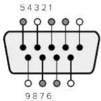
| Pin Function | |
| 1 Ground | |
| 2 Tx- (Data sent by router) | |
| 3 Rx+ (Data received by router) | |
| 4 Ground | |
| 5 NC (No connect) | |
| 6 Ground | |
| 7 Tx+ (Data sent by router) | |
| 8 Rx- (Data received by router) | |
| 9 Ground | |
Videohub RS-422 Ruler Control DB9 pin connections.
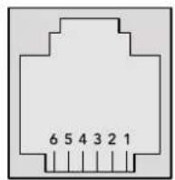
| Pin No. Function | |
| Pin 1 | TX + |
| Pin 2 | TX - |
| Pin 3 | GND |
| Pin 4 | GND |
| Pin 5 | RX - |
| Pin 6 | RX + |
Videohub RS-422 Router Control RJ11 pinout diagram.
This document describes the commands and parameters in the protocol that are relevant and supported by Videohub. Other commands and parameters specified in the Leitch protocol are accepted but ignored.
The RS-422 serial port is configured as 9600 N81.
The protocol is line-oriented, with a maximum length of 250 characters per command. Each command from the client should be terminated with a carriage-return (r). Each response from the server will be terminated with a carriage-return and line-feed (r\n).
Sources, destinations and levels are always specified in base-16, numbered from zero. Levels are always between 0 and 15 ("F"). Videohubs only have one valid level - level zero.
On connecting to the serial port, the client should send a carriage-return. The Videohub Server will respond with a > character prompt, which is not followed by a carriage-return or line-feed. Receiving the prompt indicates that a connection has been established. The same prompt will be issued after each command received by the Videohub Server.
In the following documentation, commands in orange and values in blue must be typed literally, including any spaces. In the following example of an immediate command using destination port 7 and source port 3, @ X:0/destination, source would be entered as: @ X:0/6,2
Notifications
Once connected, if status reporting is enabled, the client will receive a notification message when a route changes on the Videohub Server. The notifications take one of two forms:
S:0destination,source Routing change
This message indicates that the specified source port is now routed to the specified destination.
V:0destination,source Preset routing notification
This message indicates that the current preset includes a route from the specified source to the specified destination.
Global Commands
All pass-through commands are preceded by an 品 symbol and a space.
The following client commands are supported:
disable status reporting Status reporting is disabled by default.
@?enablestatusreporting Status reporting is enabled.
@ Z: reset routing table
Routing is reset so that the first source is routed to all destinations.
Immediate Commands
X:0/destination,source change route
X:0/destination,source/destination-2,source-2... change multiple routes The specified source ports are routed to the specified destinations. Any routing changes will trigger s: notifications
X?0destination request individual route status The source routed to a the specified destination will be returned as an s: notification.
@ S?0 request all ports route status Each source & destination port pair will be returned as s: notifications
Salvo Commands
@ P:0/destination,source queue route change
@ P:0/destination,source/destination-2,source-2... queue multiple route changes The specified routing changes are added to the current salvo for later execution.
@ P?0destination request individual port status in salvo If a routing change for the specified destination port is queued, the route will be returned as a v: notification.
@ V?0 request all ports status in salvo Each queued routing change in the salvo is reported as a v: notification.
@ B:C clear salvo
@ B:R clear salvo Any queued changes are discarded and the salvo is reset.
B: execute salvo Any queued changes are executed and each routing change will be returned as an S: notification.
Saving and Loading Labels with Telnet in Mac OS
Normally you would use Blackmagic Videohub Setup to save and load labels between different Videohub routers and to backup your videohub settings. However, if for any reason you wish to use the Terminal, the instructions below let you save and load router label configurations via the Terminal.
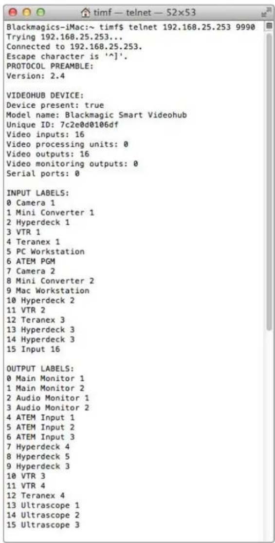
Saving Labels
1 Open the Terminal application which is located within the Applications > Utilities folder.
2Type in "telnet" and a space followed by the IP of your Videohub, then another space and "9990", which is the default port number. For example type: telnet 192.168.25.253 9990. The Protocol Preamble screen will appear.
3Copy the INPUT LABELS: text including the heading and paste into a word processor or simple text editor. Name this file "input labels" and save to your favorite location.
4Copy the OUTPUT LABELS: text including the heading and paste into a word processor or simple text editor. Name this file "output labels" and save to your favorite location.
5Close the telnet session by exiting the terminal window.
Loading Labels
1 Open the Terminal application with is located within the Applications > Utilities folder.
2Type in "telnet" and a space followed by the IP of your Videohub, then another space and "9990", which is the default port number. For example type: telnet 192.168.25.253 9990. The Protocol Preamble screen will appear.
3Open the "input labels" text file in your text editing program and copy the INPUT LABELS: text.
4 Paste this into the telnet session and press "return" twice. Telnet will respond with "ACK" and Videohub will update the input labels.
5Open the "output labels" text file in your text editing program and copy the OUTPUT LABELS; text.
6 Paste this into the telnet session and press "return" twice. Telnet will respond with "ACK" and Videohub will update the output labels.
7Close the telnet session by exiting the terminal window.
Saving and Loading Labels with Telnet in Windows
While you can save and load labels within Blackmagic Videohub Setup, you may also download and use PuTTY which is a free telnet client.
Setting up PuTTY
1 Start the application and in the "Host Name" field, type the IP of your Videohub and in the "Port" field type "9990", which is the default port number.
2From the Connection type options select the "Telnet" radio button.
3Select the "Terminal" tab and tick the "Implicit CR in every LF" checkbox.
4 Click the "Session" tab and save your session parameters by entering a name in the "Saved Sessions" field and clicking the "Save" button.
Saving Labels
1 Double click the PuTTY icon to start the application. Select your saved session from the list and click the "Load" button followed by the "Open" button. The Protocol Preamble screen will appear.
2Copy the INPUT LABELS: text including the heading and paste into a word processor or simple text editor. Name this file "input labels" and save to your favorite location.
3Copy the OUTPUT LABELS: text including the heading and paste into a word processor or simple text editor. Name this file "output labels" and save to your favorite location.
4Exit the telnet session by closing the PuTTY window.
Loading Labels
1 Double click the PuTTY icon to start the application. Select your saved session from the list and click the "Load" button followed by the "Open" button. The Protocol Preamble screen will appear.
2Open the "input labels" text file in your text editing program and copy the INPUT LABELS: text.
3 Right click in the PuTTY session to paste the copied section and press "Enter" twice. PuTTY will respond with "ACK" and Videohub will update the input labels.
4 Open the "output labels" text file in your text editing program and copy the OUTPUT LABELS: text.
5 Right click in the PuTTY session to paste the copied section and press "Enter" twice. PuTTY will respond with "ACK" and Videohub will update the output labels.
6Exit the telnet session by closing the PuTTY window.

Replacing a fan in Universal Videohub
Each fan is designed to be replaced without needing to switch off power to Videohub.
1Locate the fan tray at the base of the unit.
2Using a number 01 Phillips head screwdriver, remove the left and right screws from the fan tray.
3While supporting the tray, remove the center screw.
4 Having removed all three screws, slowly allow the fan tray to swing open until you see the black plastic dust filter on top of each fan.
Gently pull the tray towards you while continuing to swing it down until you feel the rear of the tray detach from the Universal Videohub chassis. Note which fan is faulty.
6 You will see the colored power cables connected to each fan. Each fan power cable connects to the Videohub motherboard with a plastic connector. While supporting the fan tray, unplug the plastic power connectors of all three fans. The fan tray can now be fully removed.
7 Place the fan tray on a flat surface and unclip the top of the dust-filter housing using the four clips.
8 Remove the top of the housing and the filter. Four screws will be revealed. Remove the four screws around the faulty fan. Then remove the base of the dust filter housing and also the faulty fan.
9 Replace the fan with a spare unit and then reinstate the base of the dust filter housing. Secure the housing and fan with the four screws and ensure the heads of the screws recess into the dust filter housing. If the screws fail to recess, flip over the housing and try again.
10 Place the dust filter over the base of the housing and then snap on the top of the dust filter housing.
11Position the fan tray underneath the base of the Universal Videohub chassis and connect all three fan power cables to the motherboard. All three fans should immediately start running.
12 Gently dock the rear of the fan tray with the Universal Videohub chassis. Swing up the front of the fan tray and simultaneously push the tray towards the Videohub motherboard until the rear of the fan tray slides into place and the front swings shut.
13Reinstall the three screws.
Help
Getting Help
The fastest way to obtain help is to go to the Blackmagic Design online support pages and check the latest support material available for your Blackmagic Design Videohub.
Blackmagic Design online support pages
The latest manual, software and support notes can be found at the Blackmagic Design support center at www.blackmagicdesign.com/support.
Blackmagic Design Forum
Another useful resource is the Blackmagic Design Forum. The forum is a place to find similar questions and quick solutions from either Blackmagic staff or fellow customers with extensive knowledge.
Contacting Blackmagic Design support
If you can't find the help you need in our support material, please use the "Send us an email" button to email a support request. Alternatively, click on the "Find your local support team" button and call your nearest Blackmagic Design support office.
Checking the version currently installed
To check which version of Videohub Control is installed on your computer, open the Blackmagic Videohub Control application. From the Blackmagic Videohub Control menu, select About Blackmagic Videohub and note the version number.
How to get the latest updates
After checking the version of your Blackmagic Videohub Control on your computer, please visit the Blackmagic Design support center at www.blackmagicdesign.com/support to check for the latest updates. While it is usually a good idea to run the latest updates, it is a wise practice to avoid updating any software if you are in the middle of an important project.
Regulatory Notices

Disposal of Waste of Electrical and Electronic Equipment Within the European Union.
The symbol on the product indicates that this equipment must not be disposed of with other waste materials. In order to dispose of your waste equipment, it must be handed over to a designated collection point for recycling. The separate collection and recycling of your waste equipment at the time of disposal will help conserve natural resources and ensure that it is recycled in a manner that protects human health and the environment. For more information about where you can drop off your waste equipment for recycling, please contact your local city recycling office or the dealer from whom you purchased the product.

This equipment has been tested and found to comply with the limits for a Class A digital device, pursuant to Part 15 of the FCC rules. These limits are designed to provide reasonable protection against harmful interference when the equipment is operated in a commercial environment. This equipment generates, uses, and can radiate radio frequency energy and, if not installed and used in accordance with the instructions, may cause harmful interference to radio communications. Operation of this product in a residential area is likely to cause harmful interference, in which case the user will be required to correct the interference at personal expense.
Operation is subject to the following two conditions:
1 This device may not cause harmful interference.
2 This device must accept any interference received, including interference that may cause undesired operation.

R-R-BMD-20221109001
R-R-BMD-20221109002
R-R-BMD-20221109003
MSIP-REM-BMD-201509007
MSIP-REM-BMD-201503026
MSIP-REM-BMD-201410007
MSIP-REM-BMD-201410008
MSIP-REM-BMD-201410009
MSIP-REM-BMD-201410010
MSIP-REM-BMD-201410011
MSIP-REM-BMD-201410012
MSIP-REM-BMD-201410013
MSIP-REM-BMD-201410014
R-R-BMD-201912002
R-R-BMD-201912003
ICES-3 (A) NMB-3 (A)
ISED Canada Statement
This device complies with Canadian standards for Class A digital apparatus.
Any modifications or use of this product outside its intended use could void compliance to these standards.
Connection to HDMI interfaces must be made with high quality shielded HDMI cables.
This equipment has been tested for compliance with the intended use in a commercial environment. If the equipment is used in a domestic environment, it may cause radio interference.
Safety Information
For protection against electric shock, the equipment must be connected to a mains socket outlet with a protective earth connection. In case of doubt contact a qualified electrician.
To reduce the risk of electric shock, do not expose this equipment to dripping or splashing.
Product is suitable for use in tropical locations with an ambient temperature of up to 40^
Ensure that adequate ventilation is provided around the product and that it is not restricted.
When rack mounting, ensure that the ventilation is not restricted by adjacent equipment.
No operator serviceable parts inside product. Refer servicing to your local Blackmagic Design service center.
Some products have the facility to connect small form-factor transceiver (SFP) optical fibre modules. Only use Laser class 1 optical SFP modules.
Recommended Blackmagic Design SFP modules:
-3G-SDI:PL-4F20-311C

Use only at altitudes not more than 2000m above sea level.
State of California statement
This product can expose you to chemicals such as trace amounts of polybrominated biphenyls within plastic parts, which is known to the state of California to cause cancer and birth defects or other reproductive harm.
For more information go to www.P65Warnings.ca.gov.
Warning for Authorized Service Personnel
Disconnect power from both power inlets before servicing!
Caution - Double Pole/Neutral Fusing
The power supply contained in this equipment has a fuse in both line and neutral conductors and is suitable for connection to the IT power distribution system in Norway.
Warranty
Limited Warranty
Blackmagic Design warrants that Videohub routers will be free from defects in materials and workmanship for a period of 36 months from the date of purchase excluding connectors, cables, cooling fans, fiber optic modules, fuses, keyboards and batteries which will be free from defects in materials and workmanship for a period of 12 months from the date of purchase. Blackmagic Design warrants that Videohub Master Control and Videohub Smart Control will be free from defects in materials and workmanship for a period of 12 months from the date of purchase. If a product proves to be defective during this warranty period, Blackmagic Design, at its option, either will repair the defective product without charge for parts and labor, or will provide a replacement in exchange for the defective product.
In order to obtain service under this warranty, you the Customer, must notify Blackmagic Design of the defect before the expiration of the warranty period and make suitable arrangements for the performance of service. The Customer shall be responsible for packaging and shipping the defective product to a designated service center nominated by Blackmagic Design, with shipping charges pre paid. Customer shall be responsible for paying all shipping changes, insurance, duties, taxes, and any other charges for products returned to us for any reason.
This warranty shall not apply to any defect, failure or damage caused by improper use or improper or inadequate maintenance and care. Blackmagic Design shall not be obligated to furnish service under this warranty: a) to repair damage resulting from attempts by personnel other than Blackmagic Design representatives to install, repair or service the product, b) to repair damage resulting from improper use or connection to incompatible equipment, c) to repair any damage or malfunction caused by the use of non Blackmagic Design parts or supplies, or d) to service a product that has been modified or integrated with other products when the effect of such a modification or integration increases the time or difficulty of servicing the product. THIS WARRANTY IS GIVEN BY BLACKMAGIC DESIGN IN LIEU OF ANY OTHER WARRANTYES, EXPRESS OR IMPLIED. BLACKMAGIC DESIGN AND ITS VENDORS DISCLAIMER ANY IMPLIED WARRANTYES OF MERCHANTABILITY OR FITNESS FOR A PARTICULAR PURPOSE. BLACKMAGIC DESIGN'S RESPONSIBILITY TO REPAIR OR REPLACE DEFECTIVE PRODUCTS IS THE WHOLE AND EXCLUSIVE REMEDY PROVIDED TO THE CUSTOMER FOR ANY INDIRECT, SPECIAL, INCIDENTAL OR CONSEQUENTIAL DAMAGES IRRESPECTIVE OF WHETHER BLACKMAGIC DESIGN OR THE VENDOR HAS ADVANCE NOTICE OF THE POSSIBILITY OF SUCH DAMAGES. BLACKMAGIC DESIGN IS NOT LIABLE FOR ANY ILLEGAL USE OF EQUIPMENT BY CUSTOMER. BLACKMAGIC IS NOT LIABLE FOR ANY DAMAGES RESULTING FROM USE OF THIS PRODUCT. USER OPERATES THIS PRODUCT AT OWN RISK.
Copyright 2023 Blackmagic Design. All rights reserved. 'Blackmagic Design', 'DeckLink', 'HDLink', 'Workgroup Videohub', 'Multibridge Pro', 'Multibridge Extreme', 'Intensity' and 'Leading the creative video revolution' are registered trademarks in the US and other countries. All other company and product names may be trademarks of their respective companies with which they are associated.
Blackmagic
Videohub


Blackmagic Videohub 12G
Universal Videohub
Smart Videohub CleanSwitch 12x12
Videohub Master Control Pro
Videohub Smart Control Pro
Blackmagic GPI and Tally Interface

はこ
Granth-BeThei BlackmagicDesignCEO
目次
GPI and Tally Interface

GPI and Tally Interface
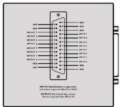
DB25コncyタ一の比n配列
This example is for the Smart Videohub which is a 16x16 router.
If the Videohub Server has no device connected, the block will simply be:
VIDEOHUB DEVICE:
Device present: false
If a device is present, but has an incompatible firmware, the status reported will be:
VIDEOHUB DEVICE:
Device present: needs update
In the last two situations, no further information will be sent, unless the situation is rectified.
If the Videohub Server detects a new Videohub attached, it will resend all blocks except the protocol preamble to indicate the device has changed, and allow the client to update its cache of server state.
Initial StatusDump
The next four blocks enumerate the labels assigned to the input, output, monitoring and serial ports.
Videohubs that do not have monitoring or serial ports do not send the corresponding blocks.
INPUT LABELS:
0VTR1
1 VTR 2
OUTPUT LABELS:
0 Output feed 1
1 Output feed 2
特此公告。
←
MONITORING OUTPUT LABELS:
0 Monitor feed 1
1 Monitor feed 2
华中特
SERIAL PORT LABELS:
0 Deck 1
1 Deck 2
NOTE Ports are always numbered starting at zero in the protocol which matches port one on the chassis.
The next three blocks describe the routing of the output, monitoring and serial ports.
VIDEO OUTPUT ROUTING:
0 5
1 3
...
< VIDEO MONITORING OUTPUT ROUTING:
0 7
1 8
...
< SERIAL PORT ROUTING:
0 12
1 11
...
Videohubs with processing units (only the Workgroup Videohub) send an extra routing block:
PROCESSING UNIT ROUTING:
0 5
1 3
…
Videohubs with frame buffers (only the Workgroup Videohub) send two extra blocks:
FRAME LABELS:
0 Frame one
1 Frame two
...
<1>
FRAME BUFFER ROUTING:
0 7
1 8
...
The next three blocks describe the locking status of the output, monitoring and serial ports. Each port has a lock status of "O" for ports that are owned by the current client (i.e., locked from the same IP address), "L" for ports that are locked from a different client, or "U" for unlocked. Note that Video hubs that do not have monitoring ports or serial ports do not send the corresponding blocks.
VIDEO OUTPUT LOCKS:
0 U<1
1U
... 一 ^ 一 MONITORING OUTPUT LOCKS:
0U
1U
...
SERIALPORT LOCKS:
0U
1U
...
Videohubs with processing units (only the Workgroup Videohub) send an extra lock block:
PROCESSING UNIT LOCKS:
0 U
1 U
...
Videohubs with frame buffers (only the Workgroup Videohub) send an extra lock block:
FRAME BUFFER LOCKS:
0 U
1 U
...
Video hubs with serial ports next send a block which describes the direction of each serial port. Each port has a direction of either "control" for the "In (Workstation)" setting, "slave" for "Out (Deck)", or "auto" for "Automatic".
SERIAL PORT DIRECTIONS:
0 control
1 slave
2 auto
...
Video hubs with pluggable cards (only Universal Video hubs) send three more blocks that describe the hardware status of the ports. Missing video or serial ports have a status of "None"; input and output video ports will be "BNC" or "Optical" if they are present; serial ports will be "RS422" if they are present.
VIDEO INPUT STATUS:
0 BNC
1 BNC
…
VIDEO OUTPUT STATUS:
0 BNC
1 BNC
…
SERIAL PORT STATUS:
0 RS422
1 RS422
…
StatusUpdates
When any route, label, or lock is changed on the Videohub Server by any client, the Videohub Server resends the applicable status block, containing only the items that have changed. For example, if serial port 6 has been unlocked, the following block will be sent:
SERIAL PORT LOCKS:
5 U
If multiple items are changed, multiple items may be present in the update:
OUTPUT LABELS:
7 New output 8 label
10 New output 11 label
If a card is plugged into or removed from the Universal Videohub, it will send hardware status blocks for the video inputs, video outputs, and serial ports on that card.
Requesting Changes
To update a label, lock or route, the client should send a block of the same form the Videohub Server sends when its status changes. For example, to change the route of output port 8 to input port 3, the client should send the following block:
VIDEO OUTPUT ROUTING:
7 2
The block must be terminated by a blank line. On receipt of a blank line, the Videohub Server will either acknowledge the request by responding:
ACK
or indicate that the request was not understood by responding:
NAK
After a positive response, the client should expect to see a status update from the Videohub Server showing the status change. This is likely to be the same as the command that was sent, but if the request could not be performed, or other changes were made simultaneously by other clients, there may be more updates in the block, or more blocks. Simultaneous updates could cancel each other out, leading to a response that is different to that expected.
In the absence of simultaneous updates, the dialog expected for a simple label change is as follows:
OUTPUT LABELS:
6 new output label seven
ACK
OUTPUT LABELS:
6 new output label seven
The asynchronous nature of the responses means that a client should never rely on the desired update actually occurring and must simply watch for status updates from the Videohub Server and use only these to update its local representation of the server state.
To lock a port, send an update to the port with the character "O" indicating that you wish to lock the port for example:
SERIAL PORT LOCKS:
7 O
ACK
SERIAL PORT LOCKS:
7 O
To forcibly unlock a port that has been locked by another client, send an update to the port with the character "F" instead of using the usual unlock character "U". For example, to override a lock on port 7:
SERIAL PORT LOCKS:
7 F
ACK
SERIAL PORT LOCKS:
7 U
Hardware status blocks can only be sent by the Videohub Server. If a client sends hardware status blocks, they will be ignored.
RequestingaStatusDump
The client may request that the Videohub Server resend the complete state of any status block by sending the header of the block, followed by a blank line. In the following example, the client requests the Videohub Server resend the output labels:
OUTPUT LABELS:
ACK
OUTPUT LABELS:
0 output label 1
1 output label 2
2 output label 3
...
CheckingtheConnection
While the connection to the Videohub Server is established, a client may send a special no-operation command to check that the Videohub Server is still responding:
PING:
←
←
If the Videohub Server is responding, it will respond with an ACK message as for any other recognized command.
VideohubRS -422Protocol
General
The RS-422 protocol can be used to control many Videohub models as RS-422 slave devices, for router crosspoint switching. This feature is available on any Videohub model with an "RS-422 Control" port.
Depending on your model of Videohub, the RS-422 port may be either a DB9 or RJ11 connector. DB9 cables are commonly available in electrical stores. The RJ11 connector is the same used in many landline telephone connections. By modifying an RS-422 to USB adapter cable terminated with an RJ11 connector you can control Videohub using external controllers via USB.
In "Leitch Server" mode, these Videohub models implement the router (server) side of the Leitch Serial Pass-Through Protocol as specified in section 4 of Leitch document SPR-MAN revision D. In "Leitch Client" mode, the Videohub implements the controller (client) side of the Leitch terminal protocol.
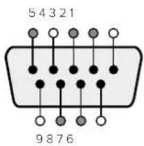
| Pin Function | |
| 1 Ground | |
| 2 Tx- (Data sent by router) | |
| 3 Rx+ (Data received by router) | |
| 4 Ground | |
| 5 NC (No connect) | |
| 6 Ground | |
| 7 Tx+ (Data sent by router) | |
| 8 Rx- (Data received by router) | |
| 9 Ground |
Videohub RS-422 Router Control DB9 pin connections.
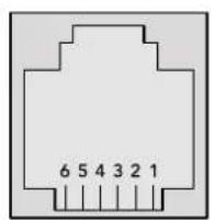
| Pin No. Function | |
| Pin 1 | TX + |
| Pin 2 | TX - |
| Pin 3 | GND |
| Pin 4 | GND |
| Pin 5 | RX - |
| Pin 6 | RX + |
Videohub RS-422 Router Control RJ11 pinout diagram.
This document describes the commands and parameters in the protocol that are relevant and supported by Videohub. Other commands and parameters specified in the Leitch protocol are accepted but ignored.
The RS-422 serial port is configured as 9600 N81.
The protocol is line-oriented, with a maximum length of 250 characters per command. Each command from the client should be terminated with a carriage-return (r). Each response from the server will be terminated with a carriage-return and line-feed (r\n).
Sources, destinations and levels are always specified in base-16, numbered from zero. Levels are always between 0 and 15 ("F"). Videohubs only have one valid level - level zero.
On connecting to the serial port, the client should send a carriage-return. The Videohub Server will respond with a > character prompt, which is not followed by a carriage-return or line-feed. Receiving the prompt indicates that a connection has been established. The same prompt will be issued after each command received by the Videohub Server.
In the following documentation, commands in orange and values in blue must be typed literally, including any spaces. In the following example of an immediate command using destination port 7 and source port 3, @ X:0/destination, source would be entered as: @ X:0/6,2
Notifications
Once connected, if status reporting is enabled, the client will receive a notification message when a route changes on the Videohub Server. The notifications take one of two forms:
S:0destination,source Routing change
This message indicates that the specified source port is now routed to the specified destination.
V:0destination,source Preset routing notification
This message indicates that the current preset includes a route from the specified source to the specified destination.
GlobalCommands
All pass-through commands are preceded by an 品 symbol and a space.
The following client commands are supported:
disable status reporting Status reporting is disabled by default.
@?enablestatusreporting Status reporting is enabled.
@ Z: reset routing table
Routing is reset so that the first source is routed to all destinations.
ImmediateCommands
X:0/destination,source change route
X:0/destination, source/destination-2, source-2... change multiple routes The specified source ports are routed to the specified destinations. Any routing changes will trigger s: notifications
X?0destination request individual route status The source routed to a the specified destination will be returned as an s: notification.
@ S?0 request all ports route status Each source & destination port pair will be returned as s: notifications
SalvoCommands
@ P:0/destination,source queue route change
P:0/destination,source/destination-2,source-2... queue multiple route changes The specified routing changes are added to the current salvo for later execution.
@ P?0destination request individual port status in salvo If a routing change for the specified destination port is queued, the route will be returned as a v: notification.
@ V?0 request all ports status in salvo Each queued routing change in the salvo is reported as a v: notification.
@ B:C clear salvo
@ B:R clear salvo Any queued changes are discarded and the salvo is reset.
B: execute salvo Any queued changes are executed and each routing change will be returned as an S: notification.
Saving and Loading Labels with Telnet in Mac OS
Normally you would use Blackmagic Videohub Setup to save and load labels between different Videohub routers and to backup your videohub settings. However, if for any reason you wish to use the Terminal, the instructions below let you save and load router label configurations via the Terminal.

SavingLabels
1 Open the Terminal application which is located within the Applications > Utilities folder.
2Type in "telnet" and a space followed by the IP of your Videohub, then another space and "9990", which is the default port number. For example type: telnet 192.168.25.253 9990. The Protocol Preamble screen will appear.
3Copy the INPUT LABELS: text including the heading and paste into a word processor or simple text editor. Name this file "input labels" and save to your favorite location.
4Copy the OUTPUT LABELS: text including the heading and paste into a word processor or simple text editor. Name this file "output labels" and save to your favorite location.
5Close the telnet session by exiting the terminal window.
LoadingLabels
1 Open the Terminal application with is located within the Applications > Utilities folder.
2Type in "telnet" and a space followed by the IP of your Videohub, then another space and "9990", which is the default port number. For example type: telnet 192.168.25.253 9990. The Protocol Preamble screen will appear.
3 Open the "input labels" text file in your text editing program and copy the INPUT LABELS: text.
4 Paste this into the telnet session and press "return" twice. Telnet will respond with "ACK" and Videohub will update the input labels.
5Open the "output labels" text file in your text editing program and copy the OUTPUT LABELS: text.
6 Paste this into the telnet session and press "return" twice. Telnet will respond with "ACK" and Videohub will update the output labels.
7Close the telnet session by exiting the terminal window.
Saving and Loading Labels with Telnet in Windows
While you can save and load labels within Blackmagic Videohub Setup, you may also download and use PuTTY which is a free telnet client.
SettingupPuTTY
1 Start the application and in the "Host Name" field, type the IP of your Videohub and in the "Port" field type "9990", which is the default port number.
2From the Connection type options select the "Telnet" radio button.
3Select the "Terminal" tab and tick the "Implicit CR in every LF" checkbox.
4 Click the "Session" tab and save your session parameters by entering a name in the "Saved Sessions" field and clicking the "Save" button.
SavingLabels
1 Double click the PuTTY icon to start the application. Select your saved session from the list and click the "Load" button followed by the "Open" button. The Protocol Preamble screen will appear.
2Copy the INPUT LABELS: text including the heading and paste into a word processor or simple text editor. Name this file "input labels" and save to your favorite location.
3Copy the OUTPUT LABELS: text including the heading and paste into a word processor or simple text editor. Name this file "output labels" and save to your favorite location.
4Exit the telnet session by closing the PuTTY window.
LoadingLabels
1 Double click the PuTTY icon to start the application. Select your saved session from the list and click the "Load" button followed by the "Open" button. The Protocol Preamble screen will appear.
2 Open the "input labels" text file in your text editing program and copy the INPUT LABELS: text.
3 Right click in the PuTTY session to paste the copied section and press "Enter" twice. PuTTY will respond with "ACK" and Videohub will update the input labels.
4 Open the "output labels" text file in your text editing program and copy the OUTPUT LABELS: text.
5 Right click in the PuTTY session to paste the copied section and press "Enter" twice. PuTTY will respond with "ACK" and Videohub will update the output labels.
6Exit the telnet session by closing the PuTTY window.

UniversalVideohubのPFNの取り外し
-3G-SDI:PL-4F20-311C

Chere cliente, cher client,
GPI and Tally Interface 230
Saving and Loading Labels
with Telnet in Mac OS 270
Saving and Loading Labels
with Telnet in Windows 271
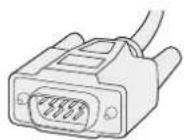
Cable series Cable standard
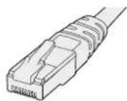
Ethernet RJ45
Alimentation
GPI and Tally Interface
Momentary Hold Video
1Branchez I'adaptateur a la GPI and Tally Interface.
The Blackmagic Videohub Ethernet Protocol is a text based protocol that is accessed by connecting to TCP port 9990 on a Videohub Server. Integrated Videohub Servers and Videohub Server computers are supported by the protocol.
The Videohub Server sends information in blocks which each have an identifying header in all-caps, followed by a full-colon. A block spans multiple lines and is terminated by a blank line. Each line in the protocol is terminated by a newline character.
Upon connection, the Videohub Server sends a complete dump of the state of the device. After the initial status dump, status updates are sent every time the Videohub status changes.
To be resilient to future protocol changes, clients should ignore blocks they do not recognize, up to the trailing blank line. Within existing blocks, clients should ignore lines they do not recognize.
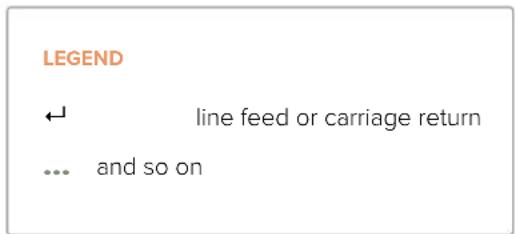
Version 2.3 of the Blackmagic Videohub Ethernet Protocol was released with Videohub 4.9.1 software.
Protocol Preamble
The first block sent by the Videohub Server is always the protocol preamble:
PROTOCOL PREAMBLE:
Version: 2.3
The version field indicates the protocol version. When the protocol is changed in a compatible way, the minor version number will be updated. If incompatible changes are made, the major version number will be updated.
Device Information
The next block contains general information about the connected Videohub device. If a device is connected, the Videohub Server will report the attributes of the Videohub:
VIDEOHUB DEVICE:
Device present: true
Model name: Blackmagic Smart Videohub
Video inputs: 16
Video processing units: 0
Video outputs: 16
Video monitoring outputs: 0
Serial ports: 0
This example is for the Smart Videohub which is a 16x16 router.
If the Videohub Server has no device connected, the block will simply be:
VIDEOHUB DEVICE:
Device present: false
←
If a device is present, but has an incompatible firmware, the status reported will be:
VIDEOHUB DEVICE:
Device present: needs update
In the last two situations, no further information will be sent, unless the situation is rectified.
If the Videohub Server detects a new Videohub attached, it will resend all blocks except the protocol preamble to indicate the device has changed, and allow the client to update its cache of server state.
Initial Status Dump
The next four blocks enumerate the labels assigned to the input, output, monitoring and serial ports.
Videohubs that do not have monitoring or serial ports do not send the corresponding blocks.
INPUT LABELS:
0VTR1
1 VTR 2
1
OUTPUT LABELS:
0 Output feed 1
1 Output feed 2
MONITORING OUTPUT LABELS:
0 Monitor feed 1
1 Monitor feed 2
解得
SERIAL PORT LABELS:
0 Deck 1
1 Deck 2
NOTE Ports are always numbered starting at zero in the protocol which matches port one on the chassis.
The next three blocks describe the routing of the output, monitoring and serial ports.
VIDEO OUTPUT ROUTING:
0 5
1 3
...
VIDEO MONITORING OUTPUT ROUTING:
0 7
1 8
...
SERIAL PORT ROUTING:
0 12
1 11
...
Videohubs with processing units (only the Workgroup Videohub) send an extra routing block:
PROCESSING UNIT ROUTING:
051 131…
Video hubs with frame buffers (only the Workgroup Videohub) send two extra blocks:
FRAME LABELS:
0 Frame one
1 Frame two
...
<1>
FRAME BUFFER ROUTING:
0 7
1 8
...
The next three blocks describe the locking status of the output, monitoring and serial ports. Each port has a lock status of "O" for ports that are owned by the current client (i.e., locked from the same IP address), "L" for ports that are locked from a different client, or "U" for unlocked. Note that Video hubs that do not have monitoring ports or serial ports do not send the corresponding blocks.
Videohubs with processing units (only the Workgroup Videohub) send an extra lock block:
PROCESSING UNIT LOCKS:
0 U
1 U
...
Videohubs with frame buffers (only the Workgroup Videohub) send an extra lock block:
FRAME BUFFER LOCKS:
0 U
1 U
…
Videohubs with serial ports next send a block which describes the direction of each serial port. Each port has a direction of either "control" for the "In (Workstation)" setting, "slave" for "Out (Deck)", or "auto" for "Automatic".
SERIAL PORT DIRECTIONS:
0 control
1 slave
2 auto
...
Videohubs with pluggable cards (only Universal Videohubs) send three more blocks that describe the hardware status of the ports. Missing video or serial ports have a status of "None"; input and output video ports will be "BNC" or "Optical" if they are present; serial ports will be "RS422" if they are present.
VIDEO INPUT STATUS:
0 BNC
1 BNC
VIDEO OUTPUT STATUS:
0 BNC
1 BNC
...
SERIAL PORT STATUS:
0 RS422
1 RS422
Status Updates
When any route, label, or lock is changed on the Videohub Server by any client, the Videohub Server resends the applicable status block, containing only the items that have changed. For example, if serial port 6 has been unlocked, the following block will be sent:
SERIAL PORT LOCKS:
5 U
←
If multiple items are changed, multiple items may be present in the update: OUTPUT LABELS:
7 New output 8 label
10 New output 11 label
If a card is plugged into or removed from the Universal Videohub, it will send hardware status blocks for the video inputs, video outputs, and serial ports on that card.
Requesting Changes
To update a label, lock or route, the client should send a block of the same form the Videohub Server sends when its status changes. For example, to change the route of output port 8 to input port 3, the client should send the following block:
VIDEO OUTPUT ROUTING:
7 2
+
The block must be terminated by a blank line. On receipt of a blank line, the Videohub Server will either acknowledge the request by responding:
ACK
or indicate that the request was not understood by responding:
NAK
After a positive response, the client should expect to see a status update from the Videohub Server showing the status change. This is likely to be the same as the command that was sent, but if the request could not be performed, or other changes were made simultaneously by other clients, there may be more updates in the block, or more blocks. Simultaneous updates could cancel each other out, leading to a response that is different to that expected.
In the absence of simultaneous updates, the dialog expected for a simple label change is as follows:
OUTPUT LABELS:
6 new output label seven
ACK
OUTPUT LABELS:
6 new output label seven
The asynchronous nature of the responses means that a client should never rely on the desired update actually occurring and must simply watch for status updates from the Videohub Server and use only these to update its local representation of the server state.
To lock a port, send an update to the port with the character "O" indicating that you wish to lock the port for example:
SERIAL PORT LOCKS:
7 O
ACK
SERIAL PORT LOCKS:
7 O
To forcibly unlock a port that has been locked by another client, send an update to the port with the character "F" instead of using the usual unlock character "U". For example, to override a lock on port 7:
SERIAL PORT LOCKS:
7 F
←
ACK
←
SERIAL PORT LOCKS:
7 U
Hardware status blocks can only be sent by the Videohub Server. If a client sends hardware status blocks, they will be ignored.
Requesting a Status Dump
The client may request that the Videohub Server resend the complete state of any status block by sending the header of the block, followed by a blank line. In the following example, the client requests the Videohub Server resend the output labels:
OUTPUT LABELS:
ACK
OUTPUT LABELS:
0 output label 1
1 output label 2
2 output label 3
...
Checking the Connection
While the connection to the Videohub Server is established, a client may send a special no-operation command to check that the Videohub Server is still responding:
PING:
If the Videohub Server is responding, it will respond with an ACK message as for any other recognized command.
Videohub RS-422 Protocol
General
The RS-422 protocol can be used to control many Videohub models as RS-422 slave devices, for router crosspoint switching. This feature is available on any Videohub model with an "RS-422 Control" port.
Depending on your model of Videohub, the RS-422 port may be either a DB9 or RJ11 connector. DB9 cables are commonly available in electrical stores. The RJ11 connector is the same used in many landline telephone connections. By modifying an RS-422 to USB adapter cable terminated with an RJ11 connector you can control Videohub using external controllers via USB.
In "Leitch Server" mode, these Videohub models implement the router (server) side of the Leitch Serial Pass-Through Protocol as specified in section 4 of Leitch document SPR-MAN revision D. In "Leitch Client" mode, the Videohub implements the controller (client) side of the Leitch terminal protocol.
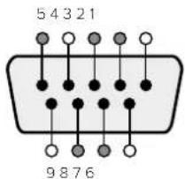
| Pin Function | |
| 1 Ground | |
| 2 Tx- (Data sent by router) | |
| 3 Rx+ (Data received by router) | |
| 4 Ground | |
| 5 NC (No connect) | |
| 6 Ground | |
| 7 Tx+ (Data sent by router) | |
| 8 Rx- (Data received by router) | |
| 9 Ground | |
Videohub RS-422 Router Control DB9 pin connections.
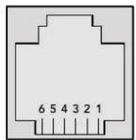
| Pin No. Function | |
| Pin 1 | TX + |
| Pin 2 | TX - |
| Pin 3 | GND |
| Pin 4 | GND |
| Pin 5 | RX - |
| Pin 6 | RX + |
Videohub RS-422 Router Control RJ11 pinout diagram.
This document describes the commands and parameters in the protocol that are relevant and supported by Videohub. Other commands and parameters specified in the Leitch protocol are accepted but ignored.
The RS-422 serial port is configured as 9600 N81.
The protocol is line-oriented, with a maximum length of 250 characters per command. Each command from the client should be terminated with a carriage-return (r). Each response from the server will be terminated with a carriage-return and line-feed (r\n).
Sources, destinations and levels are always specified in base-16, numbered from zero. Levels are always between 0 and 15 ("F"). Videohubs only have one valid level - level zero.
On connecting to the serial port, the client should send a carriage-return. The Videohub Server will respond with a > character prompt, which is not followed by a carriage-return or line-feed. Receiving the prompt indicates that a connection has been established. The same prompt will be issued after each command received by the Videohub Server.
In the following documentation, commands in orange and values in blue must be typed literally, including any spaces. In the following example of an immediate command using destination port 7 and source port 3, @ X:0/destination, source would be entered as: @ X:0/6,2
Notifications
Once connected, if status reporting is enabled, the client will receive a notification message when a route changes on the Videohub Server. The notifications take one of two forms:
S:0destination,source Routing change
This message indicates that the specified source port is now routed to the specified destination.
V:0destination,source Preset routing notification
This message indicates that the current preset includes a route from the specified source to the specified destination.
Global Commands
All pass-through commands are preceded by an 品 symbol and a space.
The following client commands are supported:
disable status reporting
Status reporting is disabled by default.
? enable status reporting
Status reporting is enabled.
@ Z: reset routing table
Routing is reset so that the first source is routed to all destinations.
Immediate Commands
X:0/destination,source change route
@ X:0/destination,source/destination-2,source-2... change multiple routes
The specified source ports are routed to the specified destinations.
Any routing changes will trigger S: notifications
@ X?Odestination request individual route status
The source routed to a the specified destination will be returned as an S: notification.
@ S?0 request all ports route status
Each source & destination port pair will be returned as S: notifications
Salvo Commands
@ P:0/destination,source queue route change
@ P:0/destination,source/destination-2,source-2... queue multiple route changes
The specified routing changes are added to the current salvo for later execution.
@ P?Odestination request individual port status in salvo
If a routing change for the specified destination port is queued, the route will be returned as
aV: notification.
@ V?0 request all ports status in salvo
Each queued routing change in the salvo is reported as a v: notification.
B:C clear salvo
@ B:R clear salvo
Any queued changes are discarded and the salvo is reset.
B: execute salvo
Any queued changes are executed and each routing change will be returned as an 8:
notification.
Saving and Loading Labels with Telnet in Mac OS
Normally you would use Blackmagic Videohub Setup to save and load labels between different Videohub routers and to backup your videohub settings. However, if for any reason you wish to use the Terminal, the instructions below let you save and load router label configurations via the Terminal.
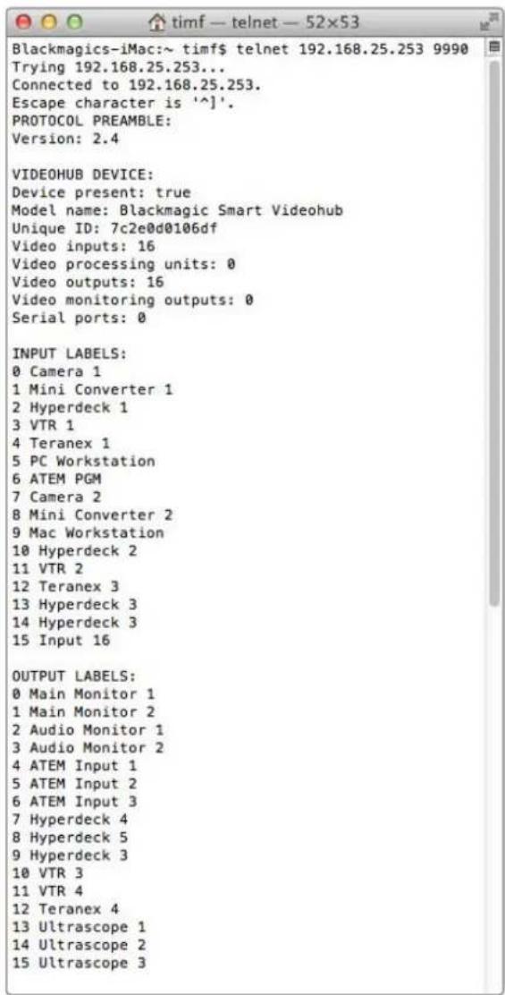
Saving Labels
1 Open the Terminal application which is located within the Applications > Utilities folder.
2Type in "telnet" and a space followed by the IP of your Videohub, then another space and "9990", which is the default port number. For example type: telnet 192.168.25.253 9990. The Protocol Preamble screen will appear.
3 Copy the INPUT LABELS: text including the heading and paste into a word processor or simple text editor. Name this file "input labels" and save to your favorite location.
4Copy the OUTPUT LABELS: text including the heading and paste into a word processor or simple text editor. Name this file "output labels" and save to your favorite location.
5Close the telnet session by exiting the terminal window.
Loading Labels
1 Open the Terminal application with is located within the Applications > Utilities folder.
2Type in "telnet" and a space followed by the IP of your Videohub, then another space and "9990", which is the default port number. For example type: telnet 192.168.25.253 9990. The Protocol Preamble screen will appear.
3 Open the "input labels" text file in your text editing program and copy the INPUT LABELS: text.
4 Paste this into the telnet session and press "return" twice. Telnet will respond with "ACK" and Videohub will update the input labels.
5Open the "output labels" text file in your text editing program and copy the OUTPUT LABELS: text.
6 Paste this into the telnet session and press "return" twice. Telnet will respond with "ACK" and Videohub will update the output labels.
7Close the telnet session by exiting the terminal window.
Saving and Loading Labels with Telnet in Windows
While you can save and load labels within Blackmagic Videohub Setup, you may also download and use PuTTY which is a free telnet client.
Setting up PuTTY
1 Start the application and in the "Host Name" field, type the IP of your Videohub and in the "Port" field type "9990", which is the default port number.
2From the Connection type options select the "Telnet" radio button.
3Select the "Terminal" tab and tick the "Implicit CR in every LF" checkbox.
4 Click the "Session" tab and save your session parameters by entering a name in the "Saved Sessions" field and clicking the "Save" button.
Saving Labels
1 Double click the PuTTY icon to start the application. Select your saved session from the list and click the "Load" button followed by the "Open" button. The Protocol Preamble screen will appear.
2 Copy the INPUT LABELS: text including the heading and paste into a word processor or simple text editor. Name this file "input labels" and save to your favorite location.
3Copy the OUTPUT LABELS: text including the heading and paste into a word processor or simple text editor. Name this file "output labels" and save to your favorite location.
4Exit the telnet session by closing the PuTTY window.
Loading Labels
1 Double click the PuTTY icon to start the application. Select your saved session from the list and click the "Load" button followed by the "Open" button. The Protocol Preamble screen will appear.
2 Open the "input labels" text file in your text editing program and copy the INPUT LABELS: text.
3 Right click in the PuTTY session to paste the copied section and press "Enter" twice. PuTTY will respond with "ACK" and Videohub will update the input labels.
4Open the "output labels" text file in your text editing program and copy the OUTPUT LABELS: text.
5 Right click in the PuTTY session to paste the copied section and press "Enter" twice. PuTTY will respond with "ACK" and Videohub will update the output labels.
Exit the telnet session by closing the PuTTY window.
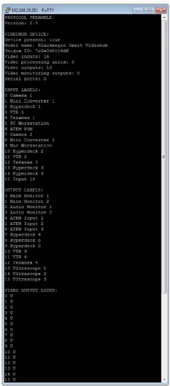
-3G-SDI:PL-4F20-311C

Blackmagic GPI and Tally Interface

Willkommen
CEO Blackmagic Design
Inhaltsverzeichnis
GPI and Tally Interface 322
Blackmagic Videohub Software 323
Blackmagic Videohub Setup 323
Saving and Loading Labels
with Telnet in Mac OS 362
Saving and Loading Labels
with Telnet in Windows 363
GPI and Tally Interface
Momentary Hold Video
The Blackmagic Videohub Ethernet Protocol is a text based protocol that is accessed by connecting to TCP port 9990 on a Videohub Server. Integrated Videohub Servers and Videohub Server computers are supported by the protocol.
The Videohub Server sends information in blocks which each have an identifying header in all-caps, followed by a full-colon. A block spans multiple lines and is terminated by a blank line. Each line in the protocol is terminated by a newline character.
Upon connection, the Videohub Server sends a complete dump of the state of the device. After the initial status dump, status updates are sent every time the Videohub status changes.
To be resilient to future protocol changes, clients should ignore blocks they do not recognize, up to the trailing blank line. Within existing blocks, clients should ignore lines they do not recognize.

Version 2.3 of the Blackmagic Videohub Ethernet Protocol was released with Videohub 4.9.1 software.
Protocol Preamble
The first block sent by the Videohub Server is always the protocol preamble:
PROTOCOL PREAMBLE:
Version: 2.3
The version field indicates the protocol version. When the protocol is changed in a compatible way, the minor version number will be updated. If incompatible changes are made, the major version number will be updated.
Device Information
The next block contains general information about the connected Videohub device. If a device is connected, the Videohub Server will report the attributes of the Videohub:
VIDEOHUB DEVICE:
Device present: true
Model name: Blackmagic Smart Videohub
Video inputs: 16
Video processing units: 0
Video outputs: 16
Video monitoring outputs: 0
Serial ports: 0
This example is for the Smart Videohub which is a 16x16 router.
If the Videohub Server has no device connected, the block will simply be:
VIDEOHUB DEVICE:
Device present: false
If a device is present, but has an incompatible firmware, the status reported will be:
VIDEOHUB DEVICE:
Device present: needs update
In the last two situations, no further information will be sent, unless the situation is rectified.
If the Videohub Server detects a new Videohub attached, it will resend all blocks except the protocol preamble to indicate the device has changed, and allow the client to update its cache of server state.
Initial Status Dump
The next four blocks enumerate the labels assigned to the input, output, monitoring and serial ports.
Videohubs that do not have monitoring or serial ports do not send the corresponding blocks.
INPUT LABELS:
0 VTR 1
1 VTR 2
OUTPUT LABELS:
0 Output feed 1
1 Output feed 2
特此公告。
←
MONITORING OUTPUT LABELS:
0 Monitor feed 1
1 Monitor feed 2
华中特
←
SERIAL PORT LABELS:
0 Deck 1
1 Deck 2
NOTE Ports are always numbered starting at zero in the protocol which matches port one on the chassis.
The next three blocks describe the routing of the output, monitoring and serial ports.
VIDEO OUTPUT ROUTING:
0 5
1 3
...
VIDEO MONITORING OUTPUT ROUTING:
0 7
1 8
...
SERIAL PORT ROUTING:
0 12
1 11
...
Videohubs with processing units (only the Workgroup Videohub) send an extra routing block:
PROCESSING UNIT ROUTING:
0 5
1 3
…
Videohubs with frame buffers (only the Workgroup Videohub) send two extra blocks:
FRAME LABELS:
0 Frame one
1 Frame two
...
<1>
FRAME BUFFER ROUTING:
0 7
1 8
...
The next three blocks describe the locking status of the output, monitoring and serial ports. Each port has a lock status of "O" for ports that are owned by the current client (i.e., locked from the same IP address), "L" for ports that are locked from a different client, or "U" for unlocked. Note that Video hubs that do not have monitoring ports or serial ports do not send the corresponding blocks.
Videohubs with processing units (only the Workgroup Videohub) send an extra lock block:
PROCESSING UNIT LOCKS:
0 U
1 U
...
Videohubs with frame buffers (only the Workgroup Videohub) send an extra lock block:
FRAME BUFFER LOCKS:
0 U
1 U
...
Videohubs with serial ports next send a block which describes the direction of each serial port. Each port has a direction of either "control" for the "In (Workstation)" setting, "slave" for "Out (Deck)", or "auto" for "Automatic".
SERIAL PORT DIRECTIONS:
0 control
1 slave
2 auto
...
Videohubs with pluggable cards (only Universal Videohubs) send three more blocks that describe the hardware status of the ports. Missing video or serial ports have a status of "None"; input and output video ports will be "BNC" or "Optical" if they are present; serial ports will be "RS422" if they are present.
VIDEO INPUT STATUS:
0 BNC
1 BNC
…
VIDEO OUTPUT STATUS:
0 BNC
1 BNC
…
SERIAL PORT STATUS:
0 RS422
1 RS422
…
Status Updates
When any route, label, or lock is changed on the Videohub Server by any client, the Videohub Server resends the applicable status block, containing only the items that have changed. For example, if serial port 6 has been unlocked, the following block will be sent:
SERIAL PORT LOCKS:
5 U
If multiple items are changed, multiple items may be present in the update:
OUTPUT LABELS:
7 New output 8 label
10 New output 11 label
If a card is plugged into or removed from the Universal Videohub, it will send hardware status blocks for the video inputs, video outputs, and serial ports on that card.
Requesting Changes
To update a label, lock or route, the client should send a block of the same form the Videohub Server sends when its status changes. For example, to change the route of output port 8 to input port 3, the client should send the following block:
VIDEO OUTPUT ROUTING:
7 2
The block must be terminated by a blank line. On receipt of a blank line, the Videohub Server will either acknowledge the request by responding:
ACK
or indicate that the request was not understood by responding:
NAK
After a positive response, the client should expect to see a status update from the Videohub Server showing the status change. This is likely to be the same as the command that was sent, but if the request could not be performed, or other changes were made simultaneously by other clients, there may be more updates in the block, or more blocks. Simultaneous updates could cancel each other out, leading to a response that is different to that expected.
In the absence of simultaneous updates, the dialog expected for a simple label change is as follows:
OUTPUT LABELS:
6 new output label seven
ACK
OUTPUT LABELS:
6 new output label seven
The asynchronous nature of the responses means that a client should never rely on the desired update actually occurring and must simply watch for status updates from the Videohub Server and use only these to update its local representation of the server state.
To lock a port, send an update to the port with the character "O" indicating that you wish to lock the port for example:
SERIAL PORT LOCKS:
7 O
ACK
SERIAL PORT LOCKS:
7 O
To forcibly unlock a port that has been locked by another client, send an update to the port with the character "F" instead of using the usual unlock character "U". For example, to override a lock on port 7:
SERIAL PORT LOCKS:
7 F
ACK
SERIAL PORT LOCKS:
7 U
Hardware status blocks can only be sent by the Videohub Server. If a client sends hardware status blocks, they will be ignored.
Requesting a Status Dump
The client may request that the Videohub Server resend the complete state of any status block by sending the header of the block, followed by a blank line. In the following example, the client requests the Videohub Server resend the output labels:
OUTPUT LABELS:
ACK
OUTPUT LABELS:
0 output label 1
1 output label 2
2 output label 3
...
Checking the Connection
While the connection to the Videohub Server is established, a client may send a special no-operation command to check that the Videohub Server is still responding:
PING:
←
←
If the Videohub Server is responding, it will respond with an ACK message as for any other recognized command.
Videohub RS-422 Protocol
General
The RS-422 protocol can be used to control many Videohub models as RS-422 slave devices, for router crosspoint switching. This feature is available on any Videohub model with an "RS-422 Control" port.
Depending on your model of Videohub, the RS-422 port may be either a DB9 or RJ11 connector. DB9 cables are commonly available in electrical stores. The RJ11 connector is the same used in many landline telephone connections. By modifying an RS-422 to USB adapter cable terminated with an RJ11 connector you can control Videohub using external controllers via USB.
In "Leitch Server" mode, these Videohub models implement the router (server) side of the Leitch Serial Pass-Through Protocol as specified in section 4 of Leitch document SPR-MAN revision D. In "Leitch Client" mode, the Videohub implements the controller (client) side of the Leitch terminal protocol.
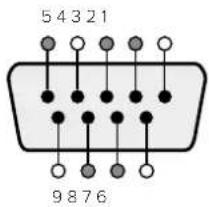
| Pin Function | |
| 1 Ground | |
| 2 Tx- (Data sent by router) | |
| 3 Rx+ (Data received by router) | |
| 4 Ground | |
| 5 NC (No connect) | |
| 6 Ground | |
| 7 Tx+ (Data sent by router) | |
| 8 Rx- (Data received by router) | |
| 9 Ground | |
Videohub RS-422 Router Control DB9 pin connections.

| Pin No. Function | |
| Pin 1 | TX + |
| Pin 2 | TX - |
| Pin 3 | GND |
| Pin 4 | GND |
| Pin 5 | RX - |
| Pin 6 | RX + |
Videohub RS-422 Router Control RJ11 pinout diagram.
This document describes the commands and parameters in the protocol that are relevant and supported by Videohub. Other commands and parameters specified in the Leitch protocol are accepted but ignored.
The RS-422 serial port is configured as 9600 N81.
The protocol is line-oriented, with a maximum length of 250 characters per command. Each command from the client should be terminated with a carriage-return (r). Each response from the server will be terminated with a carriage-return and line-feed (r\n).
Sources, destinations and levels are always specified in base-16, numbered from zero. Levels are always between 0 and 15 ("F"). Video hubs only have one valid level - level zero.
On connecting to the serial port, the client should send a carriage-return. The Videohub Server will respond with a > character prompt, which is not followed by a carriage-return or line-feed. Receiving the prompt indicates that a connection has been established. The same prompt will be issued after each command received by the Videohub Server.
In the following documentation, commands in orange and values in blue must be typed literally, including any spaces. In the following example of an immediate command using destination port 7 and source port 3, @ X:0/destination, source would be entered
as: @ X:0/6,2
Notifications
Once connected, if status reporting is enabled, the client will receive a notification message when a route changes on the Videohub Server. The notifications take one of two forms:
S:0destination,source Routing change
This message indicates that the specified source port is now routed to the specified destination.
V:0destination,source Preset routing notification
This message indicates that the current preset includes a route from the specified source to the specified destination.
Global Commands
All pass-through commands are preceded by an 品 symbol and a space.
The following client commands are supported:
disable status reporting Status reporting is disabled by default.
@?enablestatusreporting Status reporting is enabled.
@ Z: reset routing table
Routing is reset so that the first source is routed to all destinations.
Immediate Commands
X:0/destination,source change route
X:0/destination, source/destination-2, source-2... change multiple routes The specified source ports are routed to the specified destinations. Any routing changes will trigger s: notifications
X?0destination request individual route status The source routed to a the specified destination will be returned as an s: notification.
@ S?0 request all ports route status Each source & destination port pair will be returned as s: notifications
Salvo Commands
@ P:0/destination,source queue route change
P:0/destination,source/destination-2,source-2... queue multiple route changes The specified routing changes are added to the current salvo for later execution.
@ P?0destination request individual port status in salvo If a routing change for the specified destination port is queued, the route will be returned as a v: notification.
@ V?0 request all ports status in salvo Each queued routing change in the salvo is reported as a v: notification.
@ B:C clear salvo
@ B:R clear salvo Any queued changes are discarded and the salvo is reset.
B: execute salvo Any queued changes are executed and each routing change will be returned as an S: notification.
Saving and Loading Labels with Telnet in Mac OS
Normally you would use Blackmagic Videohub Setup to save and load labels between different Videohub routers and to backup your videohub settings. However, if for any reason you wish to use the Terminal, the instructions below let you save and load router label configurations via the Terminal.

Saving Labels
1 Open the Terminal application which is located within the Applications > Utilities folder.
2Type in "telnet" and a space followed by the IP of your Videohub, then another space and "9990", which is the default port number. For example type: telnet 192.168.25.253 9990. The Protocol Preamble screen will appear.
3Copy the INPUT LABELS: text including the heading and paste into a word processor or simple text editor. Name this file "input labels" and save to your favorite location.
4Copy the OUTPUT LABELS: text including the heading and paste into a word processor or simple text editor. Name this file "output labels" and save to your favorite location.
5Close the telnet session by exiting the terminal window.
Loading Labels
1 Open the Terminal application with is located within the Applications > Utilities folder.
2Type in "telnet" and a space followed by the IP of your Videohub, then another space and "9990", which is the default port number. For example type: telnet 192.168.25.253 9990. The Protocol Preamble screen will appear.
3Open the "input labels" text file in your text editing program and copy the INPUT LABELS: text.
4 Paste this into the telnet session and press "return" twice. Telnet will respond with "ACK" and Videohub will update the input labels.
5Open the "output labels" text file in your text editing program and copy the OUTPUT LABELS: text.
6 Paste this into the telnet session and press "return" twice. Telnet will respond with "ACK" and Videohub will update the output labels.
7Close the telnet session by exiting the terminal window.
Saving and Loading Labels with Telnet in Windows
While you can save and load labels within Blackmagic Videohub Setup, you may also download and use PuTTY which is a free telnet client.
Setting up PuTTY
1 Start the application and in the "Host Name" field, type the IP of your Videohub and in the "Port" field type "9990", which is the default port number.
2From the Connection type options select the "Telnet" radio button.
3Select the "Terminal" tab and tick the "Implicit CR in every LF" checkbox.
4 Click the "Session" tab and save your session parameters by entering a name in the "Saved Sessions" field and clicking the "Save" button.
Saving Labels
1 Double click the PuTTY icon to start the application. Select your saved session from the list and click the "Load" button followed by the "Open" button. The Protocol Preamble screen will appear.
2Copy the INPUT LABELS: text including the heading and paste into a word processor or simple text editor. Name this file "input labels" and save to your favorite location.
3Copy the OUTPUT LABELS: text including the heading and paste into a word processor or simple text editor. Name this file "output labels" and save to your favorite location.
4Exit the telnet session by closing the PuTTY window.
Loading Labels
1 Double click the PuTTY icon to start the application. Select your saved session from the list and click the "Load" button followed by the "Open" button. The Protocol Preamble screen will appear.
2Open the "input labels" text file in your text editing program and copy the INPUT LABELS: text.
3 Right click in the PuTTY session to paste the copied section and press "Enter" twice. PuTTY will respond with "ACK" and Videohub will update the input labels.
4 Open the "output labels" text file in your text editing program and copy the OUTPUT LABELS: text.
5 Right click in the PuTTY session to paste the copied section and press "Enter" twice. PuTTY will respond with "ACK" and Videohub will update the output labels.
6Exit the telnet session by closing the PuTTY window.

Blackmagic Design Online-Support
-3G-SDI:PL-4F20-311C

California Proposition 65
Blackmagic GPI and Tally Interface

Bienvenido
Director executivo de Blackmagic Design
Índice
Blackmagic Videohub 373
Primeros pasos 376
GPI and Tally Interface 414
Programas Blackmagic Videohub 415
Blackmagic Videohub Setup 415
Saving and Loading Labels
with Telnet in Mac OS 454
Saving and Loading Labels
with Telnet in Windows 455
GPI and Tally Interface
The Blackmagic Videohub Ethernet Protocol is a text based protocol that is accessed by connecting to TCP port 9990 on a Videohub Server. Integrated Videohub Servers and Videohub Server computers are supported by the protocol.
The Videohub Server sends information in blocks which each have an identifying header in all-caps, followed by a full-colon. A block spans multiple lines and is terminated by a blank line. Each line in the protocol is terminated by a newline character.
Upon connection, the Videohub Server sends a complete dump of the state of the device. After the initial status dump, status updates are sent every time the Videohub status changes.
To be resilient to future protocol changes, clients should ignore blocks they do not recognize, up to the trailing blank line. Within existing blocks, clients should ignore lines they do not recognize.
LEGEND
line feed or carriage return
and so on
Version 2.3 of the Blackmagic Videohub Ethernet Protocol was released with Videohub 4.9.1 software.
Protocol Preamble
The first block sent by the Videohub Server is always the protocol preamble:
PROTOCOL PREAMBLE:
Version: 2.3
The version field indicates the protocol version. When the protocol is changed in a compatible way, the minor version number will be updated. If incompatible changes are made, the major version number will be updated.
Device Information
The next block contains general information about the connected Videohub device. If a device is connected, the Videohub Server will report the attributes of the Videohub:
VIDEOHUB DEVICE:
Device present: true
Model name: Blackmagic Smart Videohub
Video inputs: 16
Video processing units: 0
Video outputs: 16
Video monitoring outputs: 0
Serial ports: 0
This example is for the Smart Videohub which is a 16x16 router.
If the Videohub Server has no device connected, the block will simply be:
VIDEOHUB DEVICE:
Device present: false
If a device is present, but has an incompatible firmware, the status reported will be:
VIDEOHUB DEVICE:
Device present: needs update
In the last two situations, no further information will be sent, unless the situation is rectified.
If the Videohub Server detects a new Videohub attached, it will resend all blocks except the protocol preamble to indicate the device has changed, and allow the client to update its cache of server state.
Initial Status Dump
The next four blocks enumerate the labels assigned to the input, output, monitoring and serial ports.
Videohubs that do not have monitoring or serial ports do not send the corresponding blocks.
INPUT LABELS:
0VTR1
1 VTR 2
OUTPUT LABELS:
0 Output feed 1
1 Output feed 2
华泰证券
MONITORING OUTPUT LABELS:
0 Monitor feed 1
1 Monitor feed 2
华
SERIAL PORT LABELS:
0 Deck 1
1 Deck 2
NOTE Ports are always numbered starting at zero in the protocol which matches port one on the chassis.
The next three blocks describe the routing of the output, monitoring and serial ports.
VIDEO OUTPUT ROUTING:
0 5
1 3
...
VIDEO MONITORING OUTPUT ROUTING:
0 7
1 8
...
SERIAL PORT ROUTING:
0 12
1 11
Videohubs with processing units (only the Workgroup Videohub) send an extra routing block:
PROCESSING UNIT ROUTING:
0 5
1 3
…
Videohubs with frame buffers (only the Workgroup Videohub) send two extra blocks:
FRAME LABELS:
0 Frame one
1 Frame two
...
<\frame buffer>
0 7
1 8
...
The next three blocks describe the locking status of the output, monitoring and serial ports. Each port has a lock status of "O" for ports that are owned by the current client (i.e., locked from the same IP address), "L" for ports that are locked from a different client, or "U" for unlocked. Note that Video hubs that do not have monitoring ports or serial ports do not send the corresponding blocks.
Videohubs with processing units (only the Workgroup Videohub) send an extra lock block:
PROCESSING UNIT LOCKS:
0 U
1 U
…
Videohubs with frame buffers (only the Workgroup Videohub) send an extra lock block:
FRAME BUFFER LOCKS:
0 U
1 U
…
←
Video hubs with serial ports next send a block which describes the direction of each serial port. Each port has a direction of either "control" for the "In (Workstation)" setting, "slave" for "Out (Deck)", or "auto" for "Automatic".
SERIAL PORT DIRECTIONS:
0 control
1 slave
2 auto
...
Videohubs with pluggable cards (only Universal Videohubs) send three more blocks that describe the hardware status of the ports. Missing video or serial ports have a status of "None"; input and output video ports will be "BNC" or "Optical" if they are present; serial ports will be "RS422" if they are present.
VIDEO INPUT STATUS:
0 BNC
1 BNC
VIDEO OUTPUT STATUS:
0 BNC
1 BNC
...
SERIAL PORT STATUS:
0 RS422
1 RS422
Status Updates
When any route, label, or lock is changed on the Videohub Server by any client, the Videohub Server resends the applicable status block, containing only the items that have changed. For example, if serial port 6 has been unlocked, the following block will be sent:
SERIAL PORT LOCKS:
5 U
←
If multiple items are changed, multiple items may be present in the update:
OUTPUT LABELS:
7 New output 8 label
10 New output 11 label
If a card is plugged into or removed from the Universal Videohub, it will send hardware status blocks for the video inputs, video outputs, and serial ports on that card.
Requesting Changes
To update a label, lock or route, the client should send a block of the same form the Videohub Server sends when its status changes. For example, to change the route of output port 8 to input port 3, the client should send the following block:
VIDEO OUTPUT ROUTING:
7 2 山
The block must be terminated by a blank line. On receipt of a blank line, the Videohub Server will either acknowledge the request by responding:
ACK
or indicate that the request was not understood by responding:
NAK
After a positive response, the client should expect to see a status update from the Videohub Server showing the status change. This is likely to be the same as the command that was sent, but if the request could not be performed, or other changes were made simultaneously by other clients, there may be more updates in the block, or more blocks. Simultaneous updates could cancel each other out, leading to a response that is different to that expected.
In the absence of simultaneous updates, the dialog expected for a simple label change is as follows:
OUTPUT LABELS:
6 new output label seven
ACK
OUTPUT LABELS:
6 new output label seven
The asynchronous nature of the responses means that a client should never rely on the desired update actually occurring and must simply watch for status updates from the Videohub Server and use only these to update its local representation of the server state.
To lock a port, send an update to the port with the character "O" indicating that you wish to lock the port for example:
SERIAL PORT LOCKS:
7 O
←
ACK
←
SERIAL PORT LOCKS:
7 O
To forcibly unlock a port that has been locked by another client, send an update to the port with the character "F" instead of using the usual unlock character "U". For example, to override a lock on port 7:
SERIAL PORT LOCKS:
7 F
ACK
SERIAL PORT LOCKS:
7 U
Hardware status blocks can only be sent by the Videohub Server. If a client sends hardware status blocks, they will be ignored.
Requesting a Status Dump
The client may request that the Videohub Server resend the complete state of any status block by sending the header of the block, followed by a blank line. In the following example, the client requests the Videohub Server resend the output labels:
OUTPUT LABELS:
ACK
OUTPUT LABELS:
0 output label 1
1 output label 2
2 output label 3
...
Checking the Connection
While the connection to the Videohub Server is established, a client may send a special no-operation command to check that the Videohub Server is still responding:
PING:
←
If the Videohub Server is responding, it will respond with an ACK message as for any other recognized command.
Videohub RS-422 Protocol
General
The RS-422 protocol can be used to control many Videohub models as RS-422 slave devices, for router crosspoint switching. This feature is available on any Videohub model with an "RS-422 Control" port.
Depending on your model of Videohub, the RS-422 port may be either a DB9 or RJ11 connector. DB9 cables are commonly available in electrical stores. The RJ11 connector is the same used in many landline telephone connections. By modifying an RS-422 to USB adapter cable terminated with an RJ11 connector you can control Videohub using external controllers via USB.
In "Leitch Server" mode, these Videohub models implement the router (server) side of the Leitch Serial Pass-Through Protocol as specified in section 4 of Leitch document SPR-MAN revision D. In "Leitch Client" mode, the Videohub implements the controller (client) side of the Leitch terminal protocol.

| Pin Function | |
| 1 Ground | |
| 2 Tx- (Data sent by router) | |
| 3 Rx+ (Data received by router) | |
| 4 Ground | |
| 5 NC (No connect) | |
| 6 Ground | |
| 7 Tx+ (Data sent by router) | |
| 8 Rx- (Data received by router) | |
| 9 Ground | |
Videohub RS-422 Router Control DB9 pin connections.
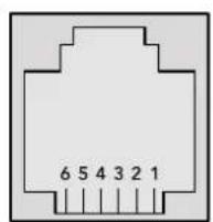
| Pin No. Function | |
| Pin 1 | TX + |
| Pin 2 | TX - |
| Pin 3 | GND |
| Pin 4 | GND |
| Pin 5 | RX - |
| Pin 6 | RX + |
Videohub RS-422 Router Control RJ11 pinout diagram.
This document describes the commands and parameters in the protocol that are relevant and supported by Videohub. Other commands and parameters specified in the Leitch protocol are accepted but ignored.
The RS-422 serial port is configured as 9600 N81.
The protocol is line-oriented, with a maximum length of 250 characters per command. Each command from the client should be terminated with a carriage-return (r). Each response from the server will be terminated with a carriage-return and line-feed (r\n).
Sources, destinations and levels are always specified in base-16, numbered from zero. Levels are always between 0 and 15 ("F"). Videohubs only have one valid level - level zero.
On connecting to the serial port, the client should send a carriage-return. The Videohub Server will respond with a > character prompt, which is not followed by a carriage-return or line-feed. Receiving the prompt indicates that a connection has been established. The same prompt will be issued after each command received by the Videohub Server.
In the following documentation, commands in orange and values in blue must be typed literally, including any spaces. In the following example of an immediate command using destination port 7 and source port 3, @ X:0/destination,source would be entered as: @ X:0/6,2
Notifications
Once connected, if status reporting is enabled, the client will receive a notification message when a route changes on the Videohub Server. The notifications take one of two forms:
S:0destination,source Routing change
This message indicates that the specified source port is now routed to the specified destination.
V:0destination,source Preset routing notification
This message indicates that the current preset includes a route from the specified source to the specified destination.
Global Commands
All pass-through commands are preceded by an 空 symbol and a space.
The following client commands are supported:
品 disable status reporting
Status reporting is disabled by default.
? enable status reporting
Status reporting is enabled.
@ Z: reset routing table
Routing is reset so that the first source is routed to all destinations.
Immediate Commands
@ X:0/destination,source change route
@ X:0/destination,source/destination-2,source-2... change multiple routes The specified source ports are routed to the specified destinations. Any routing changes will trigger S: notifications
X?Odestination request individual route status The source routed to a the specified destination will be returned as an S: notification.
@ S?0 request all ports route status Each source & destination port pair will be returned as S: notifications
Salvo Commands
@ P:0/destination,source queue route change
P:0/destination,source/destination-2,source-2... queue multiple route changes The specified routing changes are added to the current salvo for later execution.
@ P?0destination request individual port status in salvo If a routing change for the specified destination port is queued, the route will be returned as a V: notification.
@ V?0 request all ports status in salvo Each queued routing change in the salvo is reported as a V: notification.
B:C clear salvo
B:R clear salvo Any queued changes are discarded and the salvo is reset.
B: execute salvo Any queued changes are executed and each routing change will be returned as an S: notification.
Saving and Loading Labels with Telnet in Mac OS
Normally you would use Blackmagic Videohub Setup to save and load labels between different Videohub routers and to backup your videohub settings. However, if for any reason you wish to use the Terminal, the instructions below let you save and load router label configurations via the Terminal.
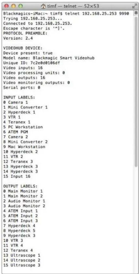
Saving Labels
1 Open the Terminal application which is located within the Applications > Utilities folder.
2Type in "telnet" and a space followed by the IP of your Videohub, then another space and "9990", which is the default port number. For example type: telnet 192.168.25.253 9990. The Protocol Preamble screen will appear.
3 Copy the INPUT LABELS: text including the heading and paste into a word processor or simple text editor. Name this file "input labels" and save to your favorite location.
4Copy the OUTPUT LABELS: text including the heading and paste into a word processor or simple text editor. Name this file "output labels" and save to your favorite location.
5Close the telnet session by exiting the terminal window.
Loading Labels
1 Open the Terminal application with is located within the Applications > Utilities folder.
2Type in "telnet" and a space followed by the IP of your Videohub, then another space and "9990", which is the default port number. For example type: telnet 192.168.25.253 9990. The Protocol Preamble screen will appear.
3 Open the "input labels" text file in your text editing program and copy the INPUT LABELS: text.
4 Paste this into the telnet session and press "return" twice. Telnet will respond with "ACK" and Videohub will update the input labels.
5Open the "output labels" text file in your text editing program and copy the OUTPUT LABELS: text.
6 Paste this into the telnet session and press "return" twice. Telnet will respond with "ACK" and Videohub will update the output labels.
7Close the telnet session by exiting the terminal window.
Saving and Loading Labels with Telnet in Windows
While you can save and load labels within Blackmagic Videohub Setup, you may also download and use PuTTY which is a free telnet client.
Setting up PuTTY
1 Start the application and in the "Host Name" field, type the IP of your Videohub and in the "Port" field type "9990", which is the default port number.
2From the Connection type options select the "Telnet" radio button.
3Select the "Terminal" tab and tick the "Implicit CR in every LF" checkbox.
4 Click the "Session" tab and save your session parameters by entering a name in the "Saved Sessions" field and clicking the "Save" button.
Saving Labels
1 Double click the PuTTY icon to start the application. Select your saved session from the list and click the "Load" button followed by the "Open" button. The Protocol Preamble screen will appear.
2 Copy the INPUT LABELS: text including the heading and paste into a word processor or simple text editor. Name this file "input labels" and save to your favorite location.
3Copy the OUTPUT LABELS: text including the heading and paste into a word processor or simple text editor. Name this file "output labels" and save to your favorite location.
4Exit the telnet session by closing the PuTTY window.
Loading Labels
1 Double click the PuTTY icon to start the application. Select your saved session from the list and click the "Load" button followed by the "Open" button. The Protocol Preamble screen will appear.
2 Open the "input labels" text file in your text editing program and copy the INPUT LABELS: text.
3 Right click in the PuTTY session to paste the copied section and press "Enter" twice. PuTTY will respond with "ACK" and Videohub will update the input labels.
4 Open the "output labels" text file in your text editing program and copy the OUTPUT LABELS; text.
5 Right click in the PuTTY session to paste the copied section and press "Enter" twice. PuTTY will respond with "ACK" and Videohub will update the output labels.
Exit the telnet session by closing the PuTTY window.
PROTOCOL PREAMBLE:
Version: 2.4
VIDEOHUB DEVICE:
Device present: true
Model name: Blackmagic Smart Videohub
Unique ID: 7c2e0d0106df
Video inputs: 16
Video processing units: 0
Video outputs: 16
Video monitoring outputs: 0
Serial ports: 0
INPUT LABELS:
0 Camera 1
1 Mini Converter 1
2 Hyperdeck 1
3 VTR 1
4 Teranex 1
5 PC Workstation
6 ATEM PGM
7 Camera 2
8 Mini Converter 2
9 Mac Workstation
10 Hyperdeck 2
11 VTR 2
12 Teranex 3
13 Hyperdeck 3
14 Hyperdeck 3
15 Input 16
OUTPUT LABELS:
0 Main Monitor 1
1 Main Monitor 2
2 Audio Monitor 1
3 Audio Monitor 2
4 ATEM Input 1
5 ATEM Input 2
6 ATEM Input 3
7 Hyperdeck 4
8 Hyperdeck 5
9 Hyperdeck 3
10 VTR 3
11 VTR 4
12 Teranex 4
13 Ultrascope 1
14 Ultrascope 2
15 Ultrascope 3
VIDEO OUTPUT LOCK3:
0 U
1 U
2 U
3 U
4 U
5 U
6 U
7 U
8 U
9 U
10 U
11 U
12 U
13 U
14 U
15 U
GPI and Tally Interface 506
Saving and Loading Labels with Telnet in Mac OS 546
Saving and Loading Labels with Telnet in Windows 547
更换Universal Videohub的风扇 549
帮助 550
监管告知 551
安全信息 552
保修 553
BlackmagicVideohub简介
GPI and Tally Interface

GPI and Tally Interface
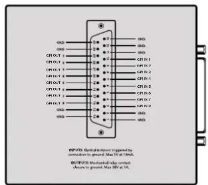
DB25接口引脚图
设置GPI and Tally Interface
配置GPI and Tally Interface
The Blackmagic Videohub Ethernet Protocol is a text based protocol that is accessed by connecting to TCP port 9990 on a Videohub Server. Integrated Videohub Servers and Videohub Server computers are supported by the protocol.
The Videohub Server sends information in blocks which each have an identifying header in all-caps, followed by a full-colon. A block spans multiple lines and is terminated by a blank line. Each line in the protocol is terminated by a newline character.
Upon connection, the Videohub Server sends a complete dump of the state of the device. After the initial status dump, status updates are sent every time the Videohub status changes.
To be resilient to future protocol changes, clients should ignore blocks they do not recognize, up to the trailing blank line. Within existing blocks, clients should ignore lines they do not recognize.
LEGEND

line feed or carriage return

and so on
Version 2.3 of the Blackmagic Videohub Ethernet Protocol was released with Videohub 4.9.1 software.
Protocol Preamble
The first block sent by the Videohub Server is always the protocol preamble:
PROTOCOL PREAMBLE:
Version: 2.3
The version field indicates the protocol version. When the protocol is changed in a compatible way, the minor version number will be updated. If incompatible changes are made, the major version number will be updated.
Device Information
The next block contains general information about the connected Videohub device. If a device is connected, the Videohub Server will report the attributes of the Videohub:
VIDEOHUB DEVICE:
Device present: true
Model name: Blackmagic Smart Videohub
Video inputs: 16
Video processing units: 0
Video outputs: 16
Video monitoring outputs: 0
Serial ports: 0
This example is for the Smart Videohub which is a 16x16 router.
If the Videohub Server has no device connected, the block will simply be:
VIDEOHUB DEVICE:
Device present: false
If a device is present, but has an incompatible firmware, the status reported will be:
VIDEOHUB DEVICE:
Device present: needs update
In the last two situations, no further information will be sent, unless the situation is rectified.
If the Videohub Server detects a new Videohub attached, it will resend all blocks except the protocol preamble to indicate the device has changed, and allow the client to update its cache of server state.
Initial Status Dump
The next four blocks enumerate the labels assigned to the input, output, monitoring and serial ports.
Videohubs that do not have monitoring or serial ports do not send the corresponding blocks.
INPUT LABELS:
0 VTR 1
1 VTR 2
OUTPUT LABELS:
0 Output feed 1
1 Output feed 2
特此公告。
←
MONITORING OUTPUT LABELS:
0 Monitor feed 1
1 Monitor feed 2
华中特
SERIAL PORT LABELS:
0 Deck 1
1 Deck 2
NOTE Ports are always numbered starting at zero in the protocol which matches port one on the chassis.
The next three blocks describe the routing of the output, monitoring and serial ports.
VIDEO OUTPUT ROUTING:
0 5
1 3
...
< VIDEO MONITORING OUTPUT ROUTING:
0 7
1 8
...
< SERIAL PORT ROUTING:
0 12
1 11
...
Videohubs with processing units (only the Workgroup Videohub) send an extra routing block:
PROCESSING UNIT ROUTING:
0 5
1 3
…
Videohubs with frame buffers (only the Workgroup Videohub) send two extra blocks:
FRAME LABELS:
0 Frame one
1 Frame two
...
<1>
FRAME BUFFER ROUTING:
0 7
1 8
...
The next three blocks describe the locking status of the output, monitoring and serial ports. Each port has a lock status of "O" for ports that are owned by the current client (i.e., locked from the same IP address), "L" for ports that are locked from a different client, or "U" for unlocked. Note that Video hubs that do not have monitoring ports or serial ports do not send the corresponding blocks.
VIDEO OUTPUT LOCKS:
0 U<1
1U
... 一 ^ 一 MONITORING OUTPUT LOCKS:
0U
1U
...
SERIALPORT LOCKS:
0U
1U
...
Videohubs with processing units (only the Workgroup Videohub) send an extra lock block:
PROCESSING UNIT LOCKS:
0 U
1 U
...
Videohubs with frame buffers (only the Workgroup Videohub) send an extra lock block:
FRAME BUFFER LOCKS:
0 U
1 U
...
Video hubs with serial ports next send a block which describes the direction of each serial port. Each port has a direction of either "control" for the "In (Workstation)" setting, "slave" for "Out (Deck)", or "auto" for "Automatic".
SERIAL PORT DIRECTIONS:
0 control
1 slave
2 auto
...
Video hubs with pluggable cards (only Universal Video hubs) send three more blocks that describe the hardware status of the ports. Missing video or serial ports have a status of "None"; input and output video ports will be "BNC" or "Optical" if they are present; serial ports will be "RS422" if they are present.
VIDEO INPUT STATUS:
0 BNC
1 BNC
…
VIDEO OUTPUT STATUS:
0 BNC
1 BNC
…
SERIAL PORT STATUS:
0 RS422
1 RS422
…
Status Updates
When any route, label, or lock is changed on the Videohub Server by any client, the Videohub Server resends the applicable status block, containing only the items that have changed. For example, if serial port 6 has been unlocked, the following block will be sent:
SERIAL PORT LOCKS:
5 U
If multiple items are changed, multiple items may be present in the update:
OUTPUT LABELS:
7 New output 8 label
10 New output 11 label
If a card is plugged into or removed from the Universal Videohub, it will send hardware status blocks for the video inputs, video outputs, and serial ports on that card.
Requesting Changes
To update a label, lock or route, the client should send a block of the same form the Videohub Server sends when its status changes. For example, to change the route of output port 8 to input port 3, the client should send the following block:
VIDEO OUTPUT ROUTING:
7 2
The block must be terminated by a blank line. On receipt of a blank line, the Videohub Server will either acknowledge the request by responding:
ACK
or indicate that the request was not understood by responding:
NAK
After a positive response, the client should expect to see a status update from the Videohub Server showing the status change. This is likely to be the same as the command that was sent, but if the request could not be performed, or other changes were made simultaneously by other clients, there may be more updates in the block, or more blocks. Simultaneous updates could cancel each other out, leading to a response that is different to that expected.
In the absence of simultaneous updates, the dialog expected for a simple label change is as follows:
OUTPUT LABELS:
6 new output label seven
ACK
OUTPUT LABELS:
6 new output label seven
The asynchronous nature of the responses means that a client should never rely on the desired update actually occurring and must simply watch for status updates from the Videohub Server and use only these to update its local representation of the server state.
To lock a port, send an update to the port with the character "O" indicating that you wish to lock the port for example:
SERIAL PORT LOCKS:
7 O
ACK
SERIAL PORT LOCKS:
7 O
To forcibly unlock a port that has been locked by another client, send an update to the port with the character "F" instead of using the usual unlock character "U". For example, to override a lock on port 7:
SERIAL PORT LOCKS:
7 F
ACK
SERIAL PORT LOCKS:
7 U
Hardware status blocks can only be sent by the Videohub Server. If a client sends hardware status blocks, they will be ignored.
Requesting a Status Dump
The client may request that the Videohub Server resend the complete state of any status block by sending the header of the block, followed by a blank line. In the following example, the client requests the Videohub Server resend the output labels:
OUTPUT LABELS:
ACK
OUTPUT LABELS:
0 output label 1
1 output label 2
2 output label 3
...
Checking the Connection
While the connection to the Videohub Server is established, a client may send a special no-operation command to check that the Videohub Server is still responding:
PING:
←
←
If the Videohub Server is responding, it will respond with an ACK message as for any other recognized command.
VideohubRS -422Protocol
General
The RS-422 protocol can be used to control many Videohub models as RS-422 slave devices, for router crosspoint switching. This feature is available on any Videohub model with an "RS-422 Control" port.
Depending on your model of Videohub, the RS-422 port may be either a DB9 or RJ11 connector. DB9 cables are commonly available in electrical stores. The RJ11 connector is the same used in many landline telephone connections. By modifying an RS-422 to USB adapter cable terminated with an RJ11 connector you can control Videohub using external controllers via USB.
In "Leitch Server" mode, these Videohub models implement the router (server) side of the Leitch Serial Pass-Through Protocol as specified in section 4 of Leitch document SPR-MAN revision D. In "Leitch Client" mode, the Videohub implements the controller (client) side of the Leitch terminal protocol.
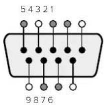
| Pin Function | |
| 1 Ground | |
| 2 Tx- (Data sent by router) | |
| 3 Rx+ (Data received by router) | |
| 4 Ground | |
| 5 NC (No connect) | |
| 6 Ground | |
| 7 Tx+ (Data sent by router) | |
| 8 Rx- (Data received by router) | |
| 9 Ground |
Videohub RS-422 Ruler Control DB9 pin connections.
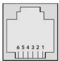
| Pin No. Function | |
| Pin 1 | TX + |
| Pin 2 | TX - |
| Pin 3 | GND |
| Pin 4 | GND |
| Pin 5 | RX - |
| Pin 6 | RX + |
Videohub RS-422 Router Control RJ11 pinout diagram.
This document describes the commands and parameters in the protocol that are relevant and supported by Videohub. Other commands and parameters specified in the Leitch protocol are accepted but ignored.
The RS-422 serial port is configured as 9600 N81.
The protocol is line-oriented, with a maximum length of 250 characters per command. Each command from the client should be terminated with a carriage-return (r). Each response from the server will be terminated with a carriage-return and line-feed (r\n).
Sources, destinations and levels are always specified in base-16, numbered from zero. Levels are always between 0 and 15 ("F"). Videohubs only have one valid level - level zero.
On connecting to the serial port, the client should send a carriage-return. The Videohub Server will respond with a > character prompt, which is not followed by a carriage-return or line-feed. Receiving the prompt indicates that a connection has been established. The same prompt will be issued after each command received by the Videohub Server.
In the following documentation, commands in orange and values in blue must be typed literally, including any spaces. In the following example of an immediate command using destination port 7 and source port 3, @ X:0/destination, source would be entered as: @ X:0/6,2
Notifications
Once connected, if status reporting is enabled, the client will receive a notification message when a route changes on the Videohub Server. The notifications take one of two forms:
S:0destination,source Routing change
This message indicates that the specified source port is now routed to the specified destination.
V:0destination,source Preset routing notification
This message indicates that the current preset includes a route from the specified source to the specified destination.
Global Commands
All pass-through commands are preceded by an 品 symbol and a space.
The following client commands are supported:
disable status reporting Status reporting is disabled by default.
@?enablestatusreporting Status reporting is enabled.
@ Z: reset routing table
Routing is reset so that the first source is routed to all destinations.
Immediate Commands
X:0/destination,source change route
X:0/destination,source/destination-2,source-2... change multiple routes The specified source ports are routed to the specified destinations. Any routing changes will trigger s: notifications
X?0destination request individual route status The source routed to a the specified destination will be returned as an s: notification.
@ S?0 request all ports route status Each source & destination port pair will be returned as s: notifications
Salvo Commands
@ P:0/destination,source queue route change
P:0/destination,source/destination-2,source-2... queue multiple route changes The specified routing changes are added to the current salvo for later execution.
@ P?0destination request individual port status in salvo If a routing change for the specified destination port is queued, the route will be returned as a v: notification.
@ V?0 request all ports status in salvo Each queued routing change in the salvo is reported as a v: notification.
@ B:C clear salvo
@ B:R clear salvo Any queued changes are discarded and the salvo is reset.
B: execute salvo Any queued changes are executed and each routing change will be returned as an S: notification.
Saving and Loading Labels with Telnet in Mac OS
Normally you would use Blackmagic Videohub Setup to save and load labels between different Videohub routers and to backup your videohub settings. However, if for any reason you wish to use the Terminal, the instructions below let you save and load router label configurations via the Terminal.
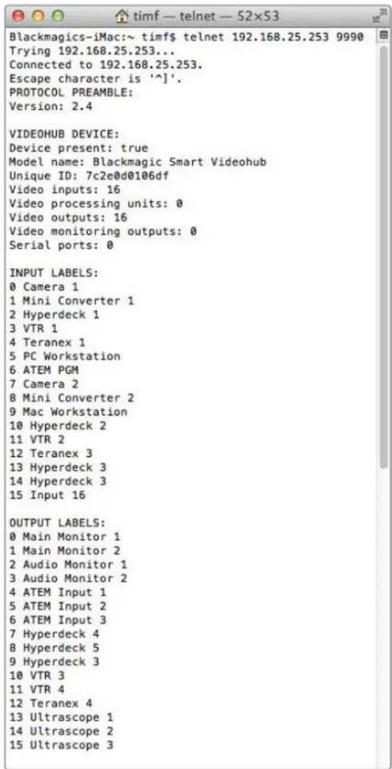
Saving Labels
1 Open the Terminal application which is located within the Applications > Utilities folder.
2Type in "telnet" and a space followed by the IP of your Videohub, then another space and "9990", which is the default port number. For example type: telnet 192.168.25.253 9990. The Protocol Preamble screen will appear.
3Copy the INPUT LABELS: text including the heading and paste into a word processor or simple text editor. Name this file "input labels" and save to your favorite location.
4Copy the OUTPUT LABELS: text including the heading and paste into a word processor or simple text editor. Name this file "output labels" and save to your favorite location.
5Close the telnet session by exiting the terminal window.
Loading Labels
1 Open the Terminal application with is located within the Applications > Utilities folder.
2Type in "telnet" and a space followed by the IP of your Videohub, then another space and "9990", which is the default port number. For example type: telnet 192.168.25.253 9990. The Protocol Preamble screen will appear.
3Open the "input labels" text file in your text editing program and copy the INPUT LABELS: text.
4 Paste this into the telnet session and press "return" twice. Telnet will respond with "ACK" and Videohub will update the input labels.
5Open the "output labels" text file in your text editing program and copy the OUTPUT LABELS: text.
6 Paste this into the telnet session and press "return" twice. Telnet will respond with "ACK" and Videohub will update the output labels.
7Close the telnet session by exiting the terminal window.
Saving and Loading Labels with Telnet in Windows
While you can save and load labels within Blackmagic Videohub Setup, you may also download and use PuTTY which is a free telnet client.
Setting up PuTTY
1 Start the application and in the "Host Name" field, type the IP of your Videohub and in the "Port" field type "9990", which is the default port number.
2From the Connection type options select the "Telnet" radio button.
3Select the "Terminal" tab and tick the "Implicit CR in every LF" checkbox.
4 Click the "Session" tab and save your session parameters by entering a name in the "Saved Sessions" field and clicking the "Save" button.
Saving Labels
1 Double click the PuTTY icon to start the application. Select your saved session from the list and click the "Load" button followed by the "Open" button. The Protocol Preamble screen will appear.
2Copy the INPUT LABELS: text including the heading and paste into a word processor or simple text editor. Name this file "input labels" and save to your favorite location.
3Copy the OUTPUT LABELS: text including the heading and paste into a word processor or simple text editor. Name this file "output labels" and save to your favorite location.
4Exit the telnet session by closing the PuTTY window.
Loading Labels
1 Double click the PuTTY icon to start the application. Select your saved session from the list and click the "Load" button followed by the "Open" button. The Protocol Preamble screen will appear.
2Open the "input labels" text file in your text editing program and copy the INPUT LABELS: text.
3 Right click in the PuTTY session to paste the copied section and press "Enter" twice. PuTTY will respond with "ACK" and Videohub will update the input labels.
4Open the "output labels" text file in your text editing program and copy the OUTPUT LABELS: text.
5 Right click in the PuTTY session to paste the copied section and press "Enter" twice. PuTTY will respond with "ACK" and Videohub will update the output labels.
6Exit the telnet session by closing the PuTTY window.

更换Universal Videohub的风扇
-3G-SDI:PL-4F20-311C

请在海拔高度2000米以下的地区使用。
加利福尼亚安全声明
Blackmagic Design of CEO,
日
目录
Blackmagic Videohub 557
560
前的用
VidiOJEnJIeHJ560
Videohub 560
彭元曦 崔志华 561
双曲化 562
双书》 563
565
Videohub 贝德·贝克 566
NeTJeK3 567
Universal Videohub 567
Universal Videohub 288 567
Universal Videohub 288 569
Universal Videohub 72 575
Universal Videohub 72 青色海
SDI.IntertpeisK3580
Universal Videohub Inerpei's Kdr 581
Universal Videohub Deck Control Cable 582
Smart Videohub CleanSwitch 12x12 583
Videohub htee er ktrnre
Videohub Master Control Pro 583
Videohub Smart Control Pro 584
Kunthu 584
15
KreTt 586
587
sssml 588
VideohubSmartControlProL
BerssKnTtRorLsR 593
VideohubSmartControlPro
XY 凭三则洛拉罗 河用
595
Blackmagic MultiView 16 595
KreTnIe 596
GPI and Tally Interface 598
Blackmagic Videohub SosFTrWee 599
Blackmagic Videohub Setup 599
100
音和的贝贝斯马德
601
币种:美元 602
Setup 603
Videohub 604
Blackmagic Videohub Control 605
Videohub 605
耘币越则奉告之 606
606
606
Blackmagic Videohub Control
hunne607
Blackmagic MultiView 16 616
Videohub Hardware Panel Setup 618
NeTJW3K 618
Videohub Master Control Pro
漢道 620
VideohubSmartControlPro
621
GPI 完全通信
帕丽华通络络通哈吉 625
Developer Information 629
Blackmagic Videohub Ethernet
Protocol v2.3 629
Videohub RS-422 Protocol 635
Saving and Loading Labels with Telnet in Mac OS 638
Saving and Loading Labels with Telnet in Windows 639
Universal Videohub 641
642
643
Anen 644
645
DAHJ 100000000000000000000000000000000000000000000000000000000000000000000000000000
<|im_start|>assistant
囀
目录键
1 OUT bitn 1
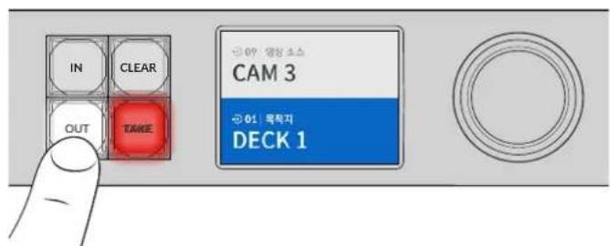
2 DECK 十K 1
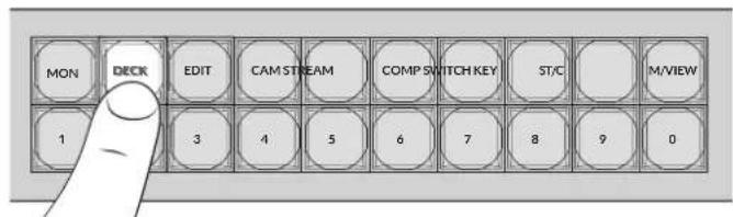
IeJrVideohubaDECKraBbIyFpHagIounDhLcRueuOuaugAanHgTaeoRnBuHm,iOJIOJIOJIOJIOJIOJIOJIOJIOJIOJIOJIOJIOJIOJIOJIOJIOJIOJIOJIOJIOJIOJIOJIOJIOJIOJIOJIOJIOJIOJIOJIOJIOJIOJIOJIOJIOJIOJIOJIOJIOJIOJIOJIOJIOJIOJIOJIOJIOJIOJIO
3 云者2能DECK2
云者币二个,LCD电一单
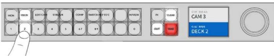
LCD用bitiooMOniTERTHJHnIiNtAIOLODOKFCHG,,
s
1 IN bitin nre r s stn kng h c
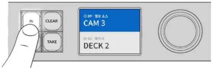
SuaHJrJrJrJrJrJrJrJrJrJrJrJrJrJrJrJrJrJrJrJrJrJrJrJrJrJrJrJrJrJrJrJrJrJrJrJrJrJrJrJrJrJrJrJrJrJrJrJrJrJrJ r J
MVDehVideohubSDI及WJF#F#E#A#J#J#J#J#J#J#J#J#J#J#J#J#J#J#J#J#J#J#J#J#J#J#J#J#J#J#J#J#J#J#J#J#J#J#J#J#J#J#J#J#J#J#J#J#J#J#J#J#J#J#
StKJeHJIeJU
Videohub ProT RalB to sAuaRz tJtH 0, AteiDts stk r h aouhry oSs J
toh j.
b
1 DESTragoftsi国默责间包藏于南之,LCDd
2 2
3 S3e 1
4 SRC'raogfuiiouoosbteuunruehngbteeHcikbIeLCDofoSpEe
5 SsKJHJU
6 TAKE버leys曾然以码普默从者用者已此币的能列,格为终将信行。TAKE币将自网则,到为,清机,到,清,到,到,到,到,到,到,到,到,到,到,到,到,到,到,到,到,到,到,到,到,到,到,到,到,到,到,到,到,到,到,到,到,到,到,到,到,到,到,到,到,到,到,到,到,到,到,到,到,到,到,
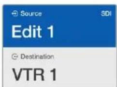
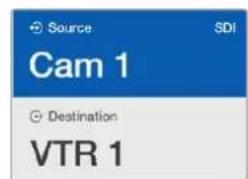
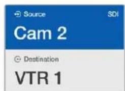
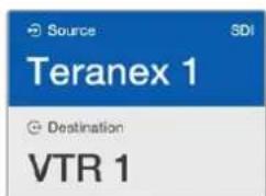
的
SAUGAJITGRTBNTIeSsKTOHJUHAGHJUHJUHJUHJUHJUHJUHJUHJUHJUHJUHJUHJUHJUHJUHJUHJUHJUHJUHJUHJUHJUHJUHJUHJUHJUH
Videohub Frt Rabl to sAuaJg aaege JcHng, i tte f stk r hch augohb bda sns f t t t t t t t t t t t t t t t t t t t t t t t t t t t t t t t t t t t t t t t t t t t t t t t t t t 0
Videohub Smart Control ProがXYデトサイously to be 100% successful, the system will be able to detect any errors. The system will be able to detect any errors in the video.
歌词→副歌
GPIandTallyInterface
Blackmagic Design GPI and Tally Interface是卡露拉该行当当的卡露有云来卡露拉长
中也的包口,
H

GPI and Tally Interface
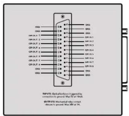
DB25 装卸器的装卸台
∈
www.blackmagicdesign.com/kr/support
KunzT 3e h 2018.
首在自的,
Inputs' & Outputs' = 'Outputs' = 'Outputs' = 'Outputs' = 'Outputs'
SsI
1 Ss 1
2 2
3 MoDnLaBbIeLreue to MaChi H Save'leqKtHSe.
LALI 1000000000000000000000000000000000000000000000000000000000000000000000000000000000000000000000
Setup' 1eep' 100000000000000000000000000000000000000000000000000000000000000000000000000
http://www.blackmagicdesign.com/kr/support)
ViDIO MONI TERLIG
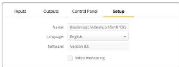
LCD上NATNNNNSOSSMDSNNDNNSNNSNNSNNSNNSNNSNNSNNSNNSNNSNNSNNSNNSNNSNNSNNSNNSNNSNNSNNSNNSNNSNNSNNSNNSNNSNNSNNSNNSNNSNNSNNSNNSNNSNNSNNSNNSNNSNNSNNSNNSNNSNNSNNSNNSNNSNNSNNSNNSNNSN
NeTrw
NTeTwKdHCPuHJ 1
NettoeV3.0.0.0 1
Videohub Control Strothreer to h Blackmagic MultiView 16 to go and panhahge chorhup s
t.
s
s
Videohub表从承用能的重回默黑migicMultiView160InataNt为,
徳自海海的公比在A面的[BlackmagicMultiView16]表TnEtoKc实定
Videohub Control Panel for Videohub Server to log in IP. Remote Videohub is Videohub Server to log in IP. Remote Videohub is Videohub Server to log in IP. Remote Videohub is Videohub Server to log in IP.
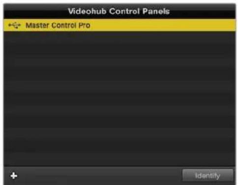
import (
USB, analogical, modem, port, signal, time, bit-rate, data, bit-rate, bit-rate, bit-rate, bit-rate, bit-rate, bit-rate, bit-rate, bit-rate, bit-rate, bit-rate, bit-rate, bit-rate, bit-rate, bit-rate, bit-rate, bit-rate, bit-rate, bit-rate, bit-rate, bit-rate, bit-rate, bit-rate, bit-rate, bit-rate, bit-rate, bit-rate, bit-rate, bit-rate, bit-rate, bit-rate, bit-rate, bit-rate, bit-rate, bit-rate,
videohub, controlPanels, port, signal, time, bit-rate, data, bit-rate, bit-rate, bit-rate, bit-rate, bit-rate, bit-rate, bit-rate, bit-rate,
port信号
)

Blackmagic Videohub Hardware Panel Setup
Inte体制克封装
IP Videohub将为帮助发布新功能,如“视频库”、“内容管理”、“内容管理与内容管理平台”等。
VideohubIP’総通対日上信默法新。Videohub社用在HSTK同T与动中IP所公
<h1 id="videohub-control">Videohub Control</h1>
Videohub Control Panel的IP挂载来显示已开启且在任何情况下 Videohub Control Panels 都可以自动加载。
注:以上数据为当前视频播放时的平均值,可能因为播放时间不同而略有差异。
1 VideohubControlPanels 建于的就 + (add device) 账户将自动
2 VideohubControlPanel 的 IP 推索到信任的平台 “OK” 路由器
3 VideohubControlPanel 1 Videohub 2
Blackmagic Videohub Hardware Panel Setup에서 희绝 썸고소의 Videohub Control Panel을 출지목halt exceedingly, 이머니에이내 USBR 对류 end off Videohub Control Panel을 유타리터에서 콘동으로 썸가해수 옷騰于此。

IP 推索所 次用海 Videohub Control Panel 视eHub Control Panels 垫默录上 云动上 首告有
<h1 id="loringsteng">LORING/STENG</h1>
Videohub Control Panel里我越完的,能到上都用在上
Videohub Control Panel的设置为“非线性”或“非线性”,在“File”或“Save Settings”或“其他”选项中可以设置为“非线性”。
図的連連連連連連連連連連連連連連連連連連連連連連連連連連連連連連連連連連連連連連連連連連連連連连连连连连连连连连连连连连连连连连连连连连连连连连连连连连连连连连连连连连连连连连连连连连连连连连连连连连连连连连连连连连连连连连连连连连连连连连连连连连连连连连连连连连连连连连连连连
<h1 id="videohubmastercontrolpro-完成终端启动">VideohubMasterControlPro 完成终端启动</h1>
Videohub Hardware Panel Setup Stéphel-Werl to Trehe Videohub Control Panel's hndwierfngu
<h1 id="section">#</h1>
'Backlight' uralaiideruwrhannnngmoukshy moan baneanrargbtei hagirtoegehns.

Videohub Master Control 有在的本网
<h1 id="把这拉斐生成他">把这拉斐生成他</h1>
Videohub Hardware Panel Setup SosFtReWor 21Ks of tRnLBe to 3000, VTR, MoNIT
T.
A.
拉斐卜萨用者吉格里德大,
IeJrVideohubMasterControlProbrtnralalblltoeepn
1 VideohubHardwarePanelSetup 那么 Videohub Control Panels 哪里从 Videohub MasterControlPro 调整到这里。
2 2
3 'OK'将咯默哈和儿有在d的拉都
4 胡氏I. 1
世際 千尼デーに ヤーダルを 知道は [ 千尼デー ヤーダル 予約 ] 備部を 壹さの

用它在把串或串或串或串或串或串或串或串或串或串或串或串或串或串或串或串或串或串或串或串或串或串或串或串或串或串或串或串或串或串或串或串或串或串或串或串或串或串或串或串或串或串或串或串或串或串或串或串或串或串或串
<h1 id="videohubsmartcontrolpro-安通终端建设">VideohubSmartControlPro 安通终端建设</h1>
Videohub Hardware Panel Setup将通过 Videohub 工具箱实现的 hdtwier功能,如在安装完后,可以使用该工具进行视频剪辑。
<h1 id="目录树">目录树</h1>
Videohub Smart Control是酷 bit 斯 凯 电 轮 里 鲁 欢 在 XY 凯 电 轮 里 鲁 里 装 章 就 定 满 有 就 会 感 不 如。酷 bit 斯 凯 电 轮 里 鲁 里 鲁 里 装 章 才 有 整 成 好 , 我 们 的 也 是 1 个 以 到 期 期
XY 凭連列表器或列表器,Videohub Smart Control Pro 从前到 24 内的木板机机台机台机台机台机台机台机台机台机台机台机台机台机台机台机台机台机台机台机台机台机台机台机台机台机台机台机台机台机台机台机台机台机台机台机台机台机台机台机台机台机台机台机台机台机台机台机台机台机台机台机

here目录树中将创建的VideohubSmartControlPro
<h1 id="kitburshangexiel">KITBURsHANGEXIEL</h1>
1 Number of Destinations' 1o
2 'Destination'버트를ql리해요.목원지상회가 endeiled Videohubの専職단자만후울 'Router SDI OutA'菲尔드에일rhahse요.목원지상회에류일라ftaSDI가 힍요한고우,'RuterSDIOutA&B'菲尔德에 odds 끽rex단자만후울일rhahayachtnida.RideRtMDTSDI的高,4개의Out'菲尔德모무에만후울일rhahayachtnida.RuterRemote'菲尔德는Videohub에서목원지상회로RS-422Дэк载体을지사해라우 tinghal格우에사용haltnya.
3 OK'
4 SsFtWeHr InterpeHIsSeHserKAsGHe HcKBeTnEeKlRHeSsBtToeH eEgeHs
5 SosKtJrAeVideohubJrRerSDInA'PfL3eJrIeHae. 50 SDI 1 4 A B PdE 20 40 40 40 40 40 40 40 40 40 40 40 40 40 40 40 40 40 40 40 40 40 40 40 40 40 40 40 40 40 40 40 40 40 4
6 OK'


司鼎LICSDI默电到用歌的云在的SDI日中
<h1 id="xykontrktlorehcngseli">XYKontrktloReHcngSeli</h1>
1 Number of Destinations' 'slaideruwr hahn ssaor draeohhre.
2 2
3 OK'
4 SsFtWeHr IerTeHIsS aEe Tae Kacagc HcKc HcKc HcKc HcKc HcKc HcKc HcKc HcKc HcKc HcKc HcKc HcKc HcKc HcKc HcKc HcKc HcKc HcKc HcKc HcKc HcKc HcKc HcKc HcKc HcKc Hc
5 SosKtJrAeVideohubJRerSDInA'PfL3EJILRTHQSDI0FJrJrA&BpTl3EaDnAeHbUeIFL3Eo,ueA~DpTl3EJrERHeHaHn. Roter Remote' pTl3eN VideohubeprrsOsStgchrsRS-422 dKcKrttojHrtae
6 OK'
<h1 id="甲克罗加">甲克罗加</h1>
如要以其他方式使用此功能,您应首先阅读本书的“使用该功能”部分。
1 Number of Macros' alsaiider to drae gohe chd 10cne mo kro bteo hsehme. kro bte
2 16
3 3

如三元山16个的三元S互元则
<h1 id="take-胡隆">TAKE 胡隆</h1>
Enable Take Button 편일만을 썼성화해荚트를 기재에이斯의 유주고에有哪些버드목상이
啤酒相关内容。
如此선都是通過使用
啤酒만 기재에만 편일만 편일만 편일만 편일만 편일만 편일만 편일만 편일만 편일만 편일만 편일만 편일만 편일만 편일만 편일만 편일만 편일만 편일만 편일만 편일만 편ernal만 편일만 편ernal만 편ernal만 편ernal만 편ernal만 편ernal만 편ernal만 편ernal만 편ernal만 편ernal만 편ernal만 편ernal만 편ernal만 편ernal만 편ernal만 편ernal만 편ernal만 편ernal만 편ernal만 편ernal만 편ernal만 편erral만 편erral만 편erral만 편erral만 편erral만 편erral만 편erral만 편erral만 편erral만 편erral만 편erral만 편erral만 편erral만 편erral만 편erral만 편erral만 편erral만 편erral不再

无
<h1 id="section-2">#</h1>
'Backlight' 히라이터를 썸고어 Backlan龙门버�의 출기을 쓸는다로 전쟁수 기용于此。 히심소스버�의 Backlan龙门버� 쓸화沙发上어 'BacklightDestinationsOnly' 히성화에서요.
<h1 id="gpi-完全性-100">GPI 完全性 100%</h1>
GPI and Tally Interfaceは言は ヤードスフロー連通を措しは8ケの GPIが複雑に発示いたします。あら電話の連絡,CCUのチイスチム連通は音楽で Videohubの連続は12ケ連続は10ケ連続は10ケ連続は10ケ連続は10ケ連続は10ケ連続は10ケ連続は10ケ連続は10ケ連続は10ケ連続は10ケ連続は10ケ連続は10ケ連続は10ケ連続は10ケ連続は10ケ連続は10ケ連続は10ケ連続是10ケ連続は10ケ連続は10ケ連続は10ケ連続は10ケ連続は10ケ連続は10ケ連続は10ケ連続は10ケ連続は10ケ連続は10ケ連続は10ケ連続は10ケ連続は10ケ連続は10ケ連続は10ケ連続は10ケ连続は10ケ連続は10ケ連続は10ケ連続は10ケ連続は10ケ連続は10ケ連続は10ケ連続は10ケ連続は10ケ連続は10ケ連続は10ケ連続は10ケ連続は10ケ連続は10ケ連続は10ケ連続は10ケ連続は1
Videohub Hardware Panel Setup的「用電」及「Output」皆是不許使用,請勿使用。
"Videohub Control Settings" 登载于数据库的数据库中,用户可以通过该链接查看数据库中的所有数据。

GPIKROsFIOInIeTcHdIeHtIeRiLWthHJHJHJHJHJHJHJHJHJHJHJHJHJHJHJHJHJHJHJHJHJHJHJHJHJHJHJHJHJHJHJHJHJHJHJHJHJHJHJHJHJHJHJHJHJHJHJHJHJHJH
<h1 id="latchvideo">LatchVideo</h1>
激活器,该函数将从视频中提取图像。该函数将从视频中提取图像。

d 那KROsfoInTgA 1
<h1 id="momentaryholdvideo">MomentaryHoldVideo</h1>
CCU的S戦チナリイスチム斯は通人会出用时击以成之,山战在式以动,自也。
<h1 id="帕里-安通-佳">帕里 安通 佳</h1>
邦通范形托式可M如,其用,云,云,云,云,云,云,云,云,云,云,云,云,云,云,云,云,云,云,云,云,云,云,云,云,云,云,云,云,云,云,云,云,云,云,云,云,云,云,云,云,云,云,云,云,云,云,云,云,云,云,
GPI and Tally Interface®是主请能的8个的GPO为该可由,其程克上动
Videohub Hardware Panel Setup的Panel BateiDoeSeer‘Input’及‘Output’PfIeD Anokou到KlrikHekroSfoInTeRtoFleGelchulsoH
<h1 id="gpomatch">GPOmatch</h1>
'GPO match' 應在認可上使用。
GPI 的形式是:
GPI 的格式为:
GPI 的格式为:
I

GPO match' 次在人到的自成海法用 GPI的KORSTFINL
<h1 id="器从-大的-gpi-and-tally-interface-本地信息-费用信-深度为">器从 大的 GPI and Tally Interface 本地信息 费用信 深度为</h1>
GPI and Tally Interface是8个的GPI和8个的GPO都用时置,当用时置时用时置时用时置时用时置时用时置时用时置时用时置时用时置时用时置时用时置时用时置时用时置时用时置时用时置时用时置时用时置时用时置时用时置时用时置时用时置时用时置时用时置时用时置时用时置时用时置时用时置
GPI and Tally Interface是Turo的IddetneFtoR到TackrHahDhanJnVideohubeEnelchH,nMzHd
tans是DnGPIandTallyInterfaceeEnelchHachs#uHsHsuHn
1 贝贝网GPIandTallyInterfacee前用到
2 Videohub トは ニデリウ克の 才区 RJ45 伊達専 冈伊比将 GPI and Tally Interface of Inder IN 十者用的
3 多遍 GPI and Tally Interface 能用到的连接
4 4
DeiJt ChieInn oI or EnyIeD oOn thc eepwE aenrHgDgH aHm Hre of Hs. gth h 1111111111111111111111111111111111111111111111111111
GPI and Tally Interface' 1000000000000000000000000000000000000000000000000000000000000000000000000000000000

iDdnte to sAonH eRr rge GPI and Tally Interface dEitj tchEiNnOuIoueHae, DteiJt chIn BpNIOUeToeJeO uNtEoEe ooi
<h1 id="netrwk3etghgpi-and-tally-interface">NeTrwK3eTgHGPi and Tally Interface</h1>
Tulnre GPI and Tally Interface of the selge to bee hae, i uon it daen kso e ane nte wkrtoan
You can use the following commands to run the code from the above command.
Uyni i dRn 30 1000000000000000000000000000000000000000000000000000000000000000000000000000000000000000000
1 VideohubControlPanels 售hahdEeHn+ (add device)
2 GPlandTallynterface 的IP主to在信的口OK"到
3 多个回程 GPI and Tally Interfacea Videohube 安全的登录和登录。

+(add device) 贝隆将下载此功能的GPI and Tally Interface的 IP 主动接口,以确保其连接。Identify 贝隆将自动连接到GPI and Tally Interface 的 LED 端口上,以便在该端口上显示信息。
<h1 id="gpi-and-tally-interface-生成器">GPI and Tally Interface 生成器</h1>
Videohub Hardware Panel Setup to use the GPI and Tally Interface's serial port. GPI and TallyInterface to use the GPI and TallyInterface to use the GPI and TallyInterface
1 GPlandTallynterface 电
2 USB TAPIN A D B KIAI BILU H GPI and Tally Interfacee kwnrter e angelshio
3 SopfTaeHreHreHreHreHreHreHreHreHreHreHreHreHreHreHreHreHreHreHreHreHreHreHreHreHreHreHreHreHreHreHreHreHreHreHreHreHreHreHreHreHreHreHreHreHreHreHreHreHreHreHRE HRE HRE HRE HRE HRE HRE HRE HRE HRE HRE HRE HRE HRE HRE HRE HRE HRE HRE HRE HRE HRE HRE HRE HRE HRE HRE HRE HRE HRE HRE HRE HRE HRE HRE HRE HRE HRE HRE HRE HRE HRE HRE HRE HRE HRE HRE HRE HRE HRE HRE
<h1 id="gpi-and-tally-interface-安全通信封装设计">GPI and Tally Interface 安全通信封装设计</h1>
SAHJ 1
1 USB TALM A D B KIeAeBnL e auag He GPI and Tally InterfacewKmTepreE anelgeh
2 GPIandTallynterface 的IddneIND相安用iEe的K
3 VideohubHardwarePanelSetup
4. 这里用“GPI and Tally Interface”加上“GPI and Tally Interface”和USB“HiKey”的内容,而“Tally Name”则在“GPI and Tally Interface”上加一个“HiKey”符号。
5 Using DHCP'及Static IP'中去IP首S端定音用音电,电电以拉网
Remote Videohub IP' pilde에서 interegahg a heng Videohub of IP ksoe to lrechse. engelit Iokoi dne thd cihn anl rne fth eonng bafik it nckxro byh, GPI and Tally Interface of LEDoe bie i dorou ni.

GPI and Tally Interface to Videohub和注册者使用浏览器登录到页面的页面地址

USB将通过连接到GPIandTallyInterface
Videohub的IP专用号将自动绑定到您的网站,您可以在浏览器中看到这个链接。
USB 凭由包为 Videohub 与 装用器 立即
2 Videohub SophtreWeerh 10
Remote Videohub IP' 孕S 菊德里有在IP孕S将如

GPI and Tally Name' pIeDre on eierou to IleRshoJ, enelshoJohar.
Hn Videhubip 1P
<h1 id="developerinformation-3">DeveloperInformation</h1>
<h1 id="blackmagic-videohub-ethernet-protocol-v23-7">Blackmagic Videohub Ethernet Protocol v2.3</h1>
<h1 id="summary-7">Summary</h1>
The Blackmagic Videohub Ethernet Protocol is a text based protocol that is accessed by connecting to TCP port 9990 on a Videohub Server. Integrated Videohub Servers and Videohub Server computers are supported by the protocol.
The Videohub Server sends information in blocks which each have an identifying header in all-caps, followed by a full-colon. A block spans multiple lines and is terminated by a blank line. Each line in the protocol is terminated by a newline character.
Upon connection, the Videohub Server sends a complete dump of the state of the device. After the initial status dump, status updates are sent every time the Videohub status changes.
To be resilient to future protocol changes, clients should ignore blocks they do not recognize, up to the trailing blank line. Within existing blocks, clients should ignore lines they do not recognize.

Version 2.3 of the Blackmagic Videohub Ethernet Protocol was released with Videohub 4.9.1 software.
<h1 id="protocolpreamble-2">ProtocolPreamble</h1>
The first block sent by the Videohub Server is always the protocol preamble:
PROTOCOL PREAMBLE:
Version: 2.3
#
The version field indicates the protocol version. When the protocol is changed in a compatible way, the minor version number will be updated. If incompatible changes are made, the major version number will be updated.
<h1 id="device-information-7">Device Information</h1>
The next block contains general information about the connected Videohub device. If a device is connected, the Videohub Server will report the attributes of the Videohub:
```txt
VIDEOHUB DEVICE:
Device present: true
Model name: Blackmagic Smart Videohub
Video inputs: 16
Video processing units: 0
Video outputs: 16
Video monitoring outputs: 0
Serial ports: 0
This example is for the Smart Videohub which is a 16x16 router.
If the Videohub Server has no device connected, the block will simply be:
VIDEOHUB DEVICE:
Device present: false
If a device is present, but has an incompatible firmware, the status reported will be:
VIDEOHUB DEVICE:
Device present: needs update
In the last two situations, no further information will be sent, unless the situation is rectified.
If the Videohub Server detects a new Videohub attached, it will resend all blocks except the protocol preamble to indicate the device has changed, and allow the client to update its cache of server state.
Initial StatusDump
The next four blocks enumerate the labels assigned to the input, output, monitoring and serial ports.
Videohubs that do not have monitoring or serial ports do not send the corresponding blocks.
INPUT LABELS:
0VTR1
1 VTR 2
特此公告。
OUTPUT LABELS:
0 Output feed 1
1 Output feed 2
MONITORING OUTPUT LABELS:
0 Monitor feed 1
1 Monitor feed 2
解得
←
SERIAL PORT LABELS:
0 Deck 1
1 Deck 2
NOTE Ports are always numbered starting at zero in the protocol which matches port one on the chassis.
The next three blocks describe the routing of the output, monitoring and serial ports.
VIDEO OUTPUT ROUTING:
0 5
1 3
...
< VIDEO MONITORING OUTPUT ROUTING:
0 7
1 8
...
< SERIAL PORT ROUTING:
0 12
1 11
...
Videohubs with processing units (only the Workgroup Videohub) send an extra routing block:
PROCESSING UNIT ROUTING:
0 5
1 3
…
Videohubs with frame buffers (only the Workgroup Videohub) send two extra blocks:
FRAME LABELS:
0 Frame one
1 Frame two
...
<1>
FRAME BUFFER ROUTING:
0 7
1 8
...
The next three blocks describe the locking status of the output, monitoring and serial ports. Each port has a lock status of "O" for ports that are owned by the current client (i.e., locked from the same IP address), "L" for ports that are locked from a different client, or "U" for unlocked. Note that Video hubs that do not have monitoring ports or serial ports do not send the corresponding blocks.
VIDEO OUTPUT LOCKS:
0 U<1
1U
... 一 MONITORING OUTPUT LOCKS:
0U
1U
...
SERIAL PORT LOCKS:
0U
1U
...
Videohubs with processing units (only the Workgroup Videohub) send an extra lock block:
PROCESSING UNIT LOCKS:
0 U
1 U
...
Videohubs with frame buffers (only the Workgroup Videohub) send an extra lock block:
FRAME BUFFER LOCKS:
0 U
1 U
...
Video hubs with serial ports next send a block which describes the direction of each serial port. Each port has a direction of either "control" for the "In (Workstation)" setting, "slave" for "Out (Deck)", or "auto" for "Automatic".
SERIAL PORT DIRECTIONS:
0 control
1 slave
2 auto
...
Video hubs with pluggable cards (only Universal Video hubs) send three more blocks that describe the hardware status of the ports. Missing video or serial ports have a status of "None"; input and output video ports will be "BNC" or "Optical" if they are present; serial ports will be "RS422" if they are present.
VIDEO INPUT STATUS:
0 BNC
1 BNC
… VIDEO OUTPUT STATUS:
0 BNC
1 BNC
…
SERIAL PORT STATUS:
0 RS422
1 RS422
…
StatusUpdates
When any route, label, or lock is changed on the Videohub Server by any client, the Videohub Server resends the applicable status block, containing only the items that have changed. For example, if serial port 6 has been unlocked, the following block will be sent:
SERIAL PORT LOCKS:
5 U
<1
If multiple items are changed, multiple items may be present in the update:
OUTPUT LABELS:
7 New output 8 label
10 New output 11 label
If a card is plugged into or removed from the Universal Videohub, it will send hardware status blocks for the video inputs, video outputs, and serial ports on that card.
Requesting Changes
To update a label, lock or route, the client should send a block of the same form the Videohub Server sends when its status changes. For example, to change the route of output port 8 to input port 3, the client should send the following block:
VIDEO OUTPUT ROUTING:
7 2
The block must be terminated by a blank line. On receipt of a blank line, the Videohub Server will either acknowledge the request by responding:
ACK←↓
or indicate that the request was not understood by responding:
NAK
After a positive response, the client should expect to see a status update from the Videohub Server showing the status change. This is likely to be the same as the command that was sent, but if the request could not be performed, or other changes were made simultaneously by other clients, there may be more updates in the block, or more blocks. Simultaneous updates could cancel each other out, leading to a response that is different to that expected.
In the absence of simultaneous updates, the dialog expected for a simple label change is as follows:
OUTPUT LABELS:
6 new output label seven
ACK
OUTPUT LABELS:
6 new output label seven
The asynchronous nature of the responses means that a client should never rely on the desired update actually occurring and must simply watch for status updates from the Videohub Server and use only these to update its local representation of the server state.
To lock a port, send an update to the port with the character "O" indicating that you wish to lock the port for example:
SERIAL PORT LOCKS:
7 O
ACK
SERIAL PORT LOCKS:
7 O
To forcibly unlock a port that has been locked by another client, send an update to the port with the character "F" instead of using the usual unlock character "U". For example, to override a lock on port 7:
SERIAL PORT LOCKS:
7 F
ACK
SERIAL PORT LOCKS:
7 U
Hardware status blocks can only be sent by the Videohub Server. If a client sends hardware status blocks, they will be ignored.
RequestingaStatusDump
The client may request that the Videohub Server resend the complete state of any status block by sending the header of the block, followed by a blank line. In the following example, the client requests the Videohub Server resend the output labels:
OUTPUT LABELS:
ACK
OUTPUT LABELS:
0 output label 1
1 output label 2
2 output label 3
...
CheckingtheConnection
While the connection to the Videohub Server is established, a client may send a special no-operation command to check that the Videohub Server is still responding:
PING:
If the Videohub Server is responding, it will respond with an ACK message as for any other recognized command.
VideohubRS -422Protocol
General
The RS-422 protocol can be used to control many Videohub models as RS-422 slave devices, for router crosspoint switching. This feature is available on any Videohub model with an "RS-422 Control" port.
Depending on your model of Videohub, the RS-422 port may be either a DB9 or RJ11 connector. DB9 cables are commonly available in electrical stores. The RJ11 connector is the same used in many landline telephone connections. By modifying an RS-422 to USB adapter cable terminated with an RJ11 connector you can control Videohub using external controllers via USB.
In "Leitch Server" mode, these Videohub models implement the router (server) side of the Leitch Serial Pass-Through Protocol as specified in section 4 of Leitch document SPR-MAN revision D. In "Leitch Client" mode, the Videohub implements the controller (client) side of the Leitch terminal protocol.

| Pin Function | |
| 1 Ground | |
| 2 Tx- (Data sent by router) | |
| 3 Rx+ (Data received by router) | |
| 4 Ground | |
| 5 NC (No connect) | |
| 6 Ground | |
| 7 Tx+ (Data sent by router) | |
| 8 Rx- (Data received by router) | |
| 9 Ground | |
Videohub RS-422 Ruler Control DB9 pin connections.
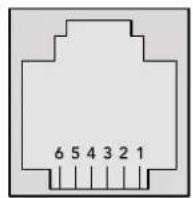
| Pin No. Function | |
| Pin 1 | TX + |
| Pin 2 | TX - |
| Pin 3 | GND |
| Pin 4 | GND |
| Pin 5 | RX - |
| Pin 6 | RX + |
Videohub RS-422 Router Control RJ11 pinout diagram.
This document describes the commands and parameters in the protocol that are relevant and supported by Videohub. Other commands and parameters specified in the Leitch protocol are accepted but ignored.
The RS-422 serial port is configured as 9600 N81.
The protocol is line-oriented, with a maximum length of 250 characters per command. Each command from the client should be terminated with a carriage-return (r). Each response from the server will be terminated with a carriage-return and line-feed (r\n).
Sources, destinations and levels are always specified in base-16, numbered from zero. Levels are always between 0 and 15 ("F"). Videohubs only have one valid level - level zero.
On connecting to the serial port, the client should send a carriage-return. The Videohub Server will respond with a > character prompt, which is not followed by a carriage-return or line-feed. Receiving the prompt indicates that a connection has been established. The same prompt will be issued after each command received by the Videohub Server.
In the following documentation, commands in orange and values in blue must be typed literally, including any spaces. In the following example of an immediate command using destination port 7 and source port 3, @ X:0/destination, source would be entered as: @ X:0/6,2
Notifications
Once connected, if status reporting is enabled, the client will receive a notification message when a route changes on the Videohub Server. The notifications take one of two forms:
S:0destination,source Routing change
This message indicates that the specified source port is now routed to the specified destination.
V:0destination,source Preset routing notification
This message indicates that the current preset includes a route from the specified source to the specified destination.
GlobalCommands
All pass-through commands are preceded by an 念 symbol and a space.
The following client commands are supported:
忍 disable status reporting
Status reporting is disabled by default.
@?enablestatusreporting
Status reporting is enabled.
@ Z: reset routing table
Routing is reset so that the first source is routed to all destinations.
ImmediateCommands
X:0/destination,source change route
X:0/destination,source/destination-2,source-2... change multiple routes
The specified source ports are routed to the specified destinations.
Any routing changes will trigger s: notifications
@ X?0destination request individual route status
The source routed to a the specified destination will be returned as an s: notification.
@ S?0 request all ports route status
Each source & destination port pair will be returned as s: notifications
SalvoCommands
@ P:0/destination,source queue route change
@ P:0/destination,source/destination-2,source-2... queue multiple route changes
The specified routing changes are added to the current salvo for later execution.
@ P?0destination request individual port status in salvo
If a routing change for the specified destination port is queued, the route will be
returned as a V: notification.
@ V?0 request all ports status in salvo
Each queued routing change in the salvo is reported as a v: notification.
B:C clear salvo
@ B:R clear salvo
Any queued changes are discarded and the salvo is reset.
B:E execute salvo
Any queued changes are executed and each routing change will be returned as an S: notification.
Saving and Loading Labels with Telnet in Mac OS
Normally you would use Blackmagic Videohub Setup to save and load labels between different Videohub routers and to backup your videohub settings. However, if for any reason you wish to use the Terminal, the instructions below let you save and load router label configurations via the Terminal.
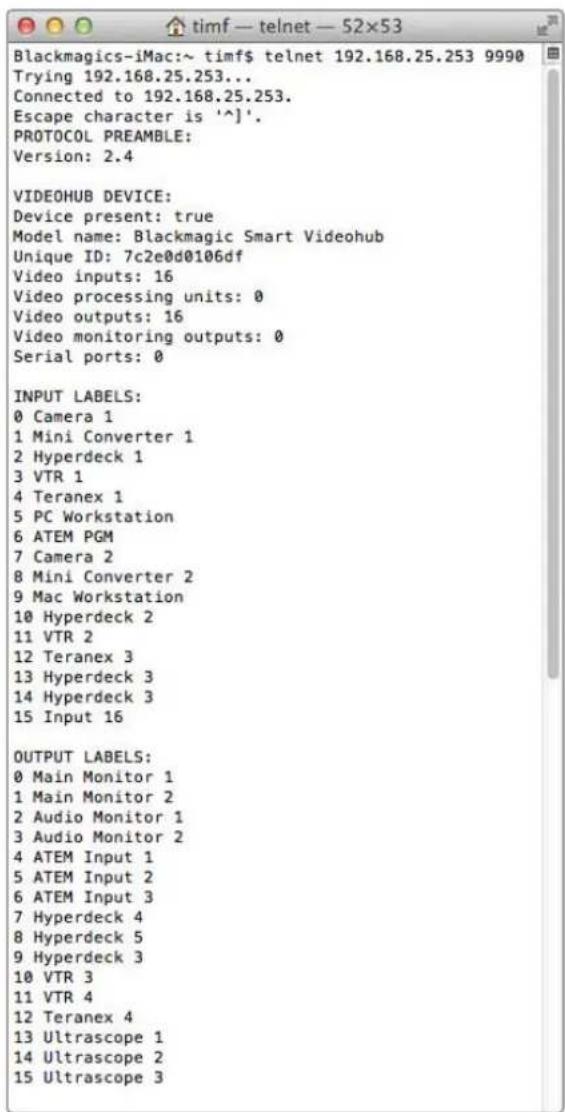
SavingLabels
1 Open the Terminal application which is located within the Applications > Utilities folder.
2Type in "telnet" and a space followed by the IP of your Videohub, then another space and "9990", which is the default port number. For example type: telnet 192.168.25.253 9990. The Protocol Preamble screen will appear.
3Copy the INPUT LABELS: text including the heading and paste into a word processor or simple text editor. Name this file "input labels" and save to your favorite location.
4Copy the OUTPUT LABELS: text including the heading and paste into a word processor or simple text editor. Name this file "output labels" and save to your favorite location.
5Close the telnet session by exiting the terminal window.
LoadingLabels
1 Open the Terminal application with is located within the Applications > Utilities folder.
2Type in "telnet" and a space followed by the IP of your Videohub, then another space and "9990", which is the default port number. For example type: telnet 192.168.25.253 9990. The Protocol Preamble screen will appear.
3 Open the "input labels" text file in your text editing program and copy the INPUT LABELS: text.
4 Paste this into the telnet session and press "return" twice. Telnet will respond with "ACK" and Videohub will update the input labels.
5Open the "output labels" text file in your text editing program and copy the OUTPUT LABELS: text.
6 Paste this into the telnet session and press "return" twice. Telnet will respond with "ACK" and Videohub will update the output labels.
7Close the telnet session by exiting the terminal window.
Saving and Loading Labels with Telnet in Windows
While you can save and load labels within Blackmagic Videohub Setup, you may also download and use PuTTY which is a free telnet client.
SettingupPuity
1 Start the application and in the "Host Name" field, type the IP of your Videohub and in the "Port" field type "9990", which is the default port number.
2From the Connection type options select the "Telnet" radio button.
3Select the "Terminal" tab and tick the "Implicit CR in every LF" checkbox.
4 Click the "Session" tab and save your session parameters by entering a name in the "Saved Sessions" field and clicking the "Save" button.
SavingLabels
1 Double click the PuTTY icon to start the application. Select your saved session from the list and click the "Load" button followed by the "Open" button. The Protocol Preamble screen will appear.
2Copy the INPUT LABELS: text including the heading and paste into a word processor or simple text editor. Name this file "input labels" and save to your favorite location.
3Copy the OUTPUT LABELS: text including the heading and paste into a word processor or simple text editor. Name this file "output labels" and save to your favorite location.
4Exit the telnet session by closing the PuTTY window.
LoadingLabels
1 Double click the PuTTY icon to start the application. Select your saved session from the list and click the "Load" button followed by the "Open" button. The Protocol Preamble screen will appear.
2 Open the "input labels" text file in your text editing program and copy the INPUT LABELS: text.
3 Right click in the PuTTY session to paste the copied section and press "Enter" twice. PuTTY will respond with "ACK" and Videohub will update the input labels.
4 Open the "output labels" text file in your text editing program and copy the OUTPUT LABELS: text.
5 Right click in the PuTTY session to paste the copied section and press "Enter" twice. PuTTY will respond with "ACK" and Videohub will update the output labels.
6Exit the telnet session by closing the PuTTY window.
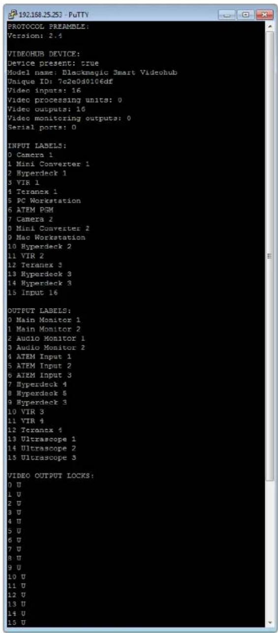
Blackmagic Design for example can use the following to show how Blackmagic design is used.
Knings BlackmagicDesignSFP 0
-3G-SDI:PL-4F20-311C

俱大,
策拉托尼阿孕
本页将对所有页面进行链接,以供您使用。
格拉尼阿泰里是德雷蒙德的“神父”。
http://www.P65Warnings.ca.gov
公在
Blackmagic GPI and Tally Interface

YBaKaembl Nolb3OBaTeJIb!
BlaTOpaPIM BAC 3a NOKyNkY KOMMyTaTopa Videohub.
Mbl CTPeMMcK TOMy, TTObI TEleBnDEHne CTANO NO-HACTOaemy TBOpueckm npoecCOM, B KOTOPOM IIO60I PPOEccHOHaJI IMeET BO3MOXHOCTb CO3daHnMaTePnAJa CaMOrO BBICOKOTo KaeeCTBa.
PaHbIe npo3BOcTBo KaueCTBeHHoro TeBn3HOHoro KOHTHa n erO noCTo6pa60Ka Tpe6oBaHn annapathoro 6obpyoBaHn cToMocTbIO MInnoHO bdoLapOB, a npofoecCNOHaNbHbIe KOMMyTaOpblc SDl-INTepfeycom 6bln OChb DOporIMn. NepexoHa h CTaHApTb HD-SDI obycnoBneH eEe 60one BbICOKmN 3aTpAmN, NOtOMy Mapwpytn3aio TAKNX CnHaNoB MoNn Ce6e No3BOJntb ToIbKO kpyhble CTyDNn N BeUaTeJIbHbIe KOMNaHN. PeuHnY Videohub MeHrOt TaKoe noLoXeHne BeSei. HeKOTOpblie MoDEnn DaHHO nnHeKn IOndepxnaIbOT He ToIbKO HD- n SDl-ΦopMaTbI, Ho n cambl coBpeMeHHbIultra HD, 6laOdaPry Hemy Cnx NMOuBo BO3MoXHa nepeDaHa 4K-BnJeO c KaJpOBn qactoto60 fps no INTEPphiCy 12G SDI.
3To pykoBODCTBO COePjNT BcIO INHΦOpMaUHO, Heo6XoDmYIO nIra pa6Otbi C KOMMyTaTOPaMn Videohub. EcnBHe 3Haete, KaK 3aDaTb IP-aIpeC i ceTeBbl e npametpbI, LyuIe BCero 60paITbcra 3a NOMouBIO K TEXHnueckOMy CneuaNlAHTy. POnkLIOueHne yctpoiCTBa He Tpe6yET Oco6bIX HabIKOB, Ondako IocNe erO yCTaHOBKn NOTpe6yETcRA BblONHHTb ONpeJeHHyIO HAcTPOIky.
IocneHIOBepcno pyKOBODCTBa n nporpaMMHO oecneueHn I
kOMMyTatopa Videohub moXHo 3arpy3ntb B pa3dene noDepxKn Ha Hauem caTe nO aDpecy
www.blackmagicdesign.com/ru. Pn 3arpy3ke o6nbHeHn Ira Videohub He 3a6ydbTe
3aperncptnpoBaTbca, T06bl noLyuAtb coo6uHn O BbInyScKe oupeHoro peN3a.Mbl
NOCTOHNO pa6tAm Hn COBepseHCTBOHaHnEM Haux npOdyKTOB, NOToMv Baun OTbIBbl
nomoryt Ham cdeNaTb nx eune lywe.
MbHaedeemc, YTO KOMMyTaOp Videohub npocnyknt Bam MHOro let n ctaHET HaedKhbIM NMOUHKOM B CTyDnPi MapwpyTnaCnHAnOB.

Ppant Nettn
Генералын діректор Blackmagic Design
CopepxaHne
Hobinka Blackmagic Videohub 649
IpoTroTOBka K pa6oTe 652
IopknloueHne nHTaHn 652
IpoikJIOUeHne NCTOuHnKOB BnDeo 652
UnpaBHeHne KOMMyTaTOpom Videohub 652
IImeHeHHe HappaBHeHn
MapwpyTN3aUNC NOMOIO
BCTpoEHHO naHEn ynpaBneHn 653
KhoNknoTOKOB 654
Pa60Ta c KHOKNKaMn BbIbopa NtOKOB 655
HanpaBHeHn MapwpyTn3aun 657
IopKIOUeHne KOMMyTaTopa
Videohub K KOMNbIOTePHoN cETn 658
YcTaHOBka CeTeBbIX HAcTpoek 659
KomMyTaOpbl Universal Videohub 659
Universal Videohub 288 659
MOHTAK KOMMYTaTopa
Universal Videohub 288 661
Universal Videohub 72 667
MOHTAX KOMMYTaTopa
Universal Videohub 72 668
INHTeppechbIe SDI-ⅡNaTbI 672
INHTeppeChbIe pntbI dIaUniversal
Videohub 673
Universal Videohub Deck Control Cable 674
Smart Videohub CleanSwitch 12x12 675
Annapathhe naHn Videohub 675
Videohub Master Control Pro 675
Videohub Smart Control Pro 676
Pa60Ta c nHaHbU ynpaBHeHn 676
IopkIoueHneK cetn Ethernet 677
TecToBa npOBepKa KHONoK Ha
naneynynpablenen 678
UPOBHeBaOpraHn3aun
MapupyTu3aun 679
Bb6Op nCTOuHKnOB u
IpiHmHKOB CnHaHa 680
IcnoB3OBAHne naHn Videohub
Smart Control Pro dny u npablenia
nprmbim nepekeIIOueHHeM 685
IcnoJIb3OBAHnE nAHeJI Videohub
Smart Control Pro dnyu npablenia
npekeKIOUeHnEMBDbAsha 686
IobabHeHne npbIKOB Ha KhoNKn 687
Blackmagic MultiView 16 687
Pa6oTa c naneBIO ynpaBHeHn 688
GPI and Tally Interface 690
NO Blackmagic Videohub 691
Blackmagic Videohub Setup 691
Saving and Loading Labels
with Telnet in Mac OS 730
Saving and Loading Labels
with Telnet in Windows 731
3aMeHaBeHTnIaTopaHa
Universal Videohub 733
ПOMOць 734
Co6IIOeHHe HOpMaTHBbIX Tpe6ObaHm 735
Ppabuna 6e3oNaChocn 736
Tapaantna 737
Hobinka Blackmagic Videohub
YcTpoIcTbO Blackmagic Videohub npnHaIeXnK nHeKe KOMMyTaTOPOB, npEHa3HaueHHbIX dNtyn n ploaJok IIO6oYoPOBH. Ha BcEx MoINΦKAuaNX npEyCMOTpeHO NOkIouHeNe uepe3 Ethernet dny ydaJIeHHoro BHeHrero ynpaBHeHn annapaTHbIM nI nporpaMMbIM cnocobm c nomoiBIO npinoXeHn Videohub Control.
KOMmyTatopbl Blackmagic Videohub 10x10 12G, 20x20 12G n 40x40 12G ochaehbl INThepfemcom 12G-SDI n BCTpoeHn noHneBIO npabLeHHa, a TaKke oBecepeuBAOT noDpekky φopmata Ultra HD 2160p/60. DaHHbIe MoEJIy UcTaHaBnBAiOT Ha CTONE IIN pa3MeaAOT B CTOKe C NOMUoi KpenJeHH, BXoJAAIX B KOMPiKeT NoCTaBKn.


Blackmagic Videohub 10x10 12G


Blackmagic Videohub 20x20 12G

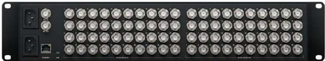
Blackmagic Videohub 40x40 12G
Moden Universal Videohub 288 n Universal Videohub 72 npedctabnIOT co6oKpyHbke KOMMyTaTOpb moynbHoro Tnpa c nHTepfecom 3G-SDI, npedHa3NaeHHbIe dIg 6OJIbux CTyDn I pnoaJok, rpe6yeTc noKnIOueHe 3NaHTeBHO ra6opa HD-06OpydoBaHn.

Universal Videohub 288
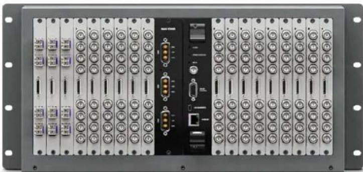
Universal Videohub 72
ModenbSmart Videohub CleanSwitch 12x12 npedctabneta co0yctahnbaemB ctoky KOMMyTATOP C nHTepfcm6G-SDI, NOBtPOH CNHXPOH3aueH Na KaXDM BXOe DnA YnCTORO nepeKIOUeHnnpn BbIOBe CnHaONBa MOHtOp Nn HEnocpeDCTBeHHo B eΦnp.
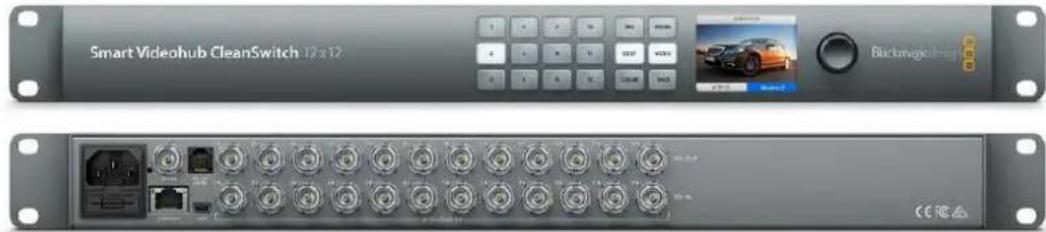
Smart Videohub CleanSwitch 12x12
BHeuHne annapathtbe npbTv Videohub Master Control Pro n Smart Control Pro oecneuBaot ynpaBHeHne cnctemamn napametpoB,doCTyHbIMn Ha moeJx Blackmagic Videohub 12G. OhnpedHa3NaueHb Ira pa60Tc MoDnFkauaunrM Universal Videohub 72 n Universal Videohub 288, Ondako nx TaKxe MOxHO NcNoIb3OBaT bIra perynipOBKn HAcTpoE KIO6OFO kOMMyTaTopa Videohub, noocoeHNHeHOro K OOnH JokalbHoCen Ethernet.
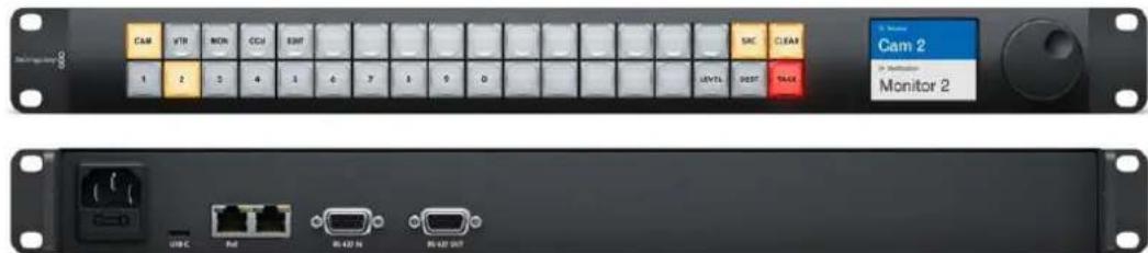
Videohub Master Control Pro
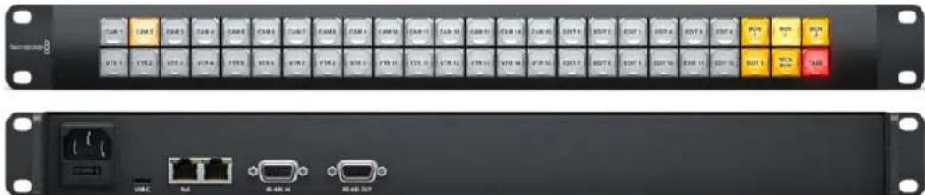
Videohub Smart Control Pro
Повтовka к paбote
Yto6bHauatbpaboty cKOMmyatopom Videohub,doCTaTOHNO NOkIIOHTb NITAHHe, NOcOeINHtB HcTouHnBnDoeoN O6OpyObaHne IraNoIyehnCnHaHa.
Co3dAnHe cepBepa IP Videohub c nOmoBIO KOHBeptepa Teranex Mini IP Video 12G
Ecnny Hxno co3daTb cepBep IP Videohub nla Mapuyn3aun cnHnOB npn pa6ote c konhepertapmN Blackmagic Teranex Mini IP Video 12G, cm. pykoBoCTBO no Teranex Mini IP Video 12G (doctynho nla 3arpy3kn no aDpecy www.blackmagicdesign.com/ru/support).
NodkloucheHne nTaHn
PoncoeunHte cnIOBn KaebI no cTaNapTy IEC K pa3bemy NtAHnHa KOMMyTaTope.
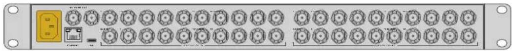
Pn nepBOM BkHoueHH yctpoiCTBa Ha KK-dncnnee noaBntc npednoKeHne Bb6paTb 3bIK. NobopoTOM kpyrNoI pyuHaNte HxKbI BapnaHT n HaxMNTe KhoNky SET.
NodkloueHne nCTOuHKnOB Bndeo
1POncoeHnHte nCTouHnKn BnDeo K SDI-BxOaam KOMMyTaTopa Videohub.
2Подклioчite obopуобанne ДЯп пиема сгнанов K SDI-БыхомКOMMyTaTopa Videohub.
Ha SDI-pa3bemax BbIOJIHЯETcA ABTomATnueckoe ONpeJeIeHne BCex IOdApKINBaEMbIX FOpMaTOB.
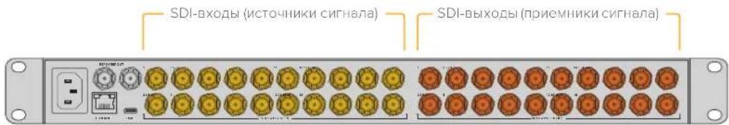
IoiKIOHTe IcTOHNI BnEo IOOBaHne IJI npHeMa CnHAnOB K SDI-BXoAM N BixOaM KOMMyTatopa Videohub
2HaMMITE KhoNky DECK.

TenepbBce BbXoDb, codepkaunbe B npIbke ndeHTnKAtop DECK, cTaHOBtca DocTyHbIMn, a npYrHe He oTo6paKaIOTc. OHn OTCOpTnpOBaHb B uCNoBOM nopAKe dnn Bb6opa KhoNkamn C HmOpamn.
3ДЯ ВьбopaВТОРОpeKOPDEpaHaxMITEKHONkycLФро2.
OHa 3aropntc, a Ha KK-dncnnee oTo6pa3rTc BbI6paHHbE BbIXoI npneMHNK CnHaJa.
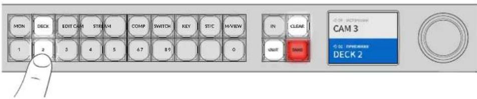
COBET. Ecnn nn KK-dncnne aKTHBnPOBaHa onu moHHTOPnRa BnDeo,TO Bby yBnnte n3obpaexene, noctynaooee B Tekyun MoneHT Ha daHHb IpneMHNK CnHaIa, a TaKKe HObbl doabHeHHb NcToyHK. DnnoTBePxeHHB bibopa HaxmTe TAKE. AKTBAuaN MOHTOpHra BnDeo ocUeCTBnEerTcpe3 HacTpOKn KK-dncnnernn tytnrty Blackmagic Videohub Setup.
Bb6op nctouHnka
1ДЯпекра DA B pexIM Bbl6pa NaCTOCHNka HaxMnte KhoNky IN.
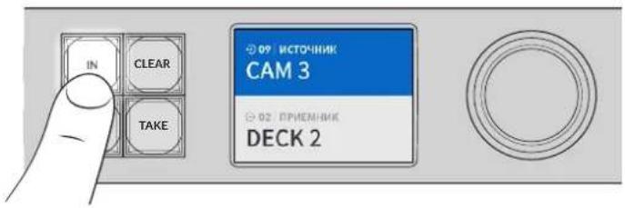
2HaXMMTe KONKy CAM.
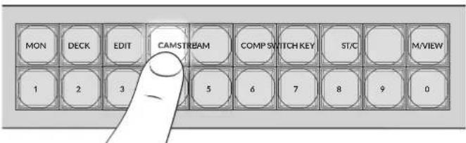
Iocne 3TOrO cTahOBaTcA DcctyHbIMn Bce BxOdbi, coepjkaUne B npIbke nEHTnFokaTOp CAM, aDpyrHe He OTo6paKaIoTc. OHn OTCopTnPoBaHbI B uCNOBOM nopJKe IJIa BbIbopa KHOKnKaMn C HOMepAMn.
3ДЯ BыбopaВторйKaМерьнХКНКусиФю2.
OHa 3aRopntc, a Ha KK-dncnnee oTo6pa3rTaBb6paHHbIe NCToOHNk BxOJ.
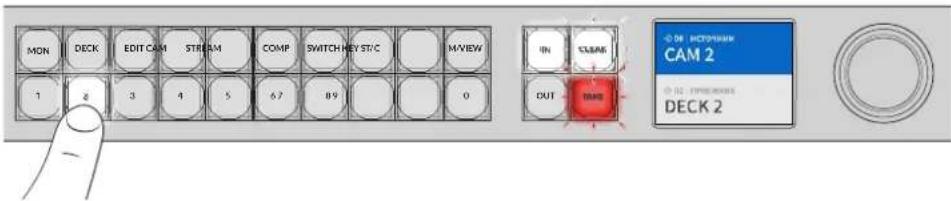
HaxMMTE KhoNky TAKE IJnnoTbcpxKdEnnry BbIbopa HappaBHeHn Mapuyn3aun.
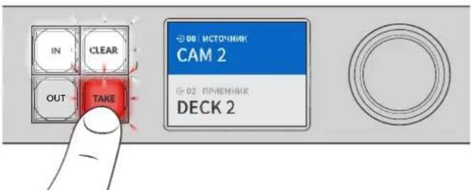
Бл Okи探测ка и разблOkи探测ка Наразвленners Mapштунзацни
Ha moDenx Blackmagic Videohub yctaHabnBaTb n ChmMaTb 6NoKIpOBKy HanpaBHeHn MapuTy3aun MoXHO C NOMOsbU BCTpoEHNO nepeHne NaHEn. IJN 6NoKIpOBKn BbIpaHnro B daHbI MOneHT BixOda HaxMTe KhoNky LOCK. IocJIe 3rTO pRdom cero ImHeH Ma KK-dncnlee NoBtca 3HaQOK 3Amka.
PopdoK6nokpObKndpyIroBbIXoDa
1HaXmTe KhoNky OUT.
2C NOMOuBIO COOTBeTCTByIOUxN KHOJOK HIN KpyrILOI pyKIN BbIEpeNTe HOBbIB BbIXoD.
3HaMMTe KhoNky LOCK.
Praom c imHeem BixOHa Ha KK-dncnlee noaBntc 3HaQK 3AMKa. KhoKa LOCK taKke 3aRopaetc npn BbIbOp eonpeJeHHO BixOHa, TIO6bl IpOdoMeHCTpnpoBaT HeBO3MOXHOCTb n3meHHe HnPaBHeHn Do Tex nop, noka OH He 6yDet pa3bokupoBaH.
Yto6bpa36IOKINPOBaB BixO, HaxMITE eue pa3 KhoNky LOCK.
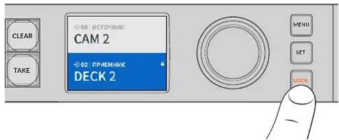
Yto6bI He Doynctntb nepeknioeHna ciHana c BbipahHoro BbIXOa, HaxMMTE KhoNky 6nokpabKn
Dpyro cnoc6 6nokropBbixoHa - HaxaTb ydepXnBaTB KhoNky OUT Ha npotxkeHm DByx cekyHd do tex nop, noka Ha KK-dncnnee He noBntc3HaOk 3aMka. TTo6bl pa36nKnpoBaTb Bixo, eue pa3 HaxmTe u depXnBaTe daHyIO KhoNky B TeueHne DByxCekyHd.
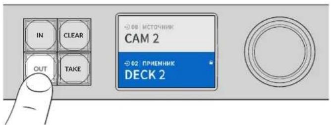
Pn6noknpOBKe BbXoHa KK-dncnnee oTo6paKaetc3HaQOK 3aMka
COBET. Ecnn onpeeneHnn npemHnK cnHa nha 3a6noKnpoBaH,ero HeBO3MOXHO 13MeHHTb HaxaTne KHOIOK NCTOCHNk nn BxOJa.
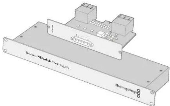
BloK Universal Videohub Power Supply nMeet pa3Mep 1RU n BkIoouaet Bce6nIaTy NtAHH, KOtopyIO NOKnIOuAOCT C nOMOUbIO CNoBOrKa6eJIa
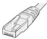
CtanhapthbI Ethernet-ka6enbc pa3bcmOM RJ45
MoHTax KOMMyTaTopa Universal Videohub 288
IoiKoMMyTaTOp Universal Videohub 288 n 6nok nntaHna Ha 2 RU HeoXoIMMo npedyCMOTpeTb 25 CBOOdbhIX MeCT B CTOnKe, YTObI oBecneuHT b OTBOI TEIIa. EcIn yCTpOJCTBO yCTaHaBnBaIOT B cAMOM BepxY cToiKn, NOTpe6yeTcA 23 CBOOdbhIX MecTa.
BbCota KOMMyTatopa Universal Videohub 288 coctabniet 18 RU, rnybHa - 15,24 cm. YcpoiCTBO MOXHO yCTaHOBtB IuueBOI Nn TbIbHOI CTOpOHoi, a TaKKe 3a npyMm O6opyDobAHnEM.
KOMMyTaOp Universal Videohub 288 codepXHT YyBCTBnBhIe K CTaTnueckomy 3neKtpnuectBy KOMnoHeHbI. Npepa6oTo C taKIMN KOMNoHEtAMn HxHHO o6raTeNbHO CHrTb CTaTnueckoe 3neKtpnuecTBO - TaK Jee, KaN npu yCTaHOBKe DeTaneH Ha KOMnbIOTeP. B NOdo6HbIX cnyaRex peKOMHeHdyETcNcNOb3OBAb aHTNCtATnueckn 6pcAet.
YcTaHOBka KOMMyTaUHHO MaTpncbI Universal Videohub 288 Crosspoint
Iocne toro kaK moeJIb Universal Videohub 288 yctaHOBnHa B cToKy, ee Heo6xOIMO oChactntb KOMMyTaIOHHo MaTpiuei. TaKaMaTpiuca RaBnErcy ceHTpaNbHbIM 3JeMeHToM ycTpoiCTBa, obecneuBaI nepeDaU cyrHana B 3aDaHHom HnPaBnEHn U npaBnHeNc DeKOJ. Matpuiy Universal Videohub 288 Crosspoint MoXHo yCTaHabNBaTb N3BNeKeTaTb HeNoCpeDCTBeHNO BO Bpem paBoTb yCTpoiCTBa.

1B3aBnCb 3a Dba pbyaKka KOMMytaHNoHHo MaTPnUcbl, yepxNBAte ee B BepTnKaIbHOM noLoKeHN. Pa3bem BNC, npT Ethernet n npyRne INTepeeCbI dOJXHb HaxOHTbcra Bn3y MaTPnUcbl.
2Octopoxho yctaHOBITE Matpuy BnpdHa3HaeHHb IJI Hee Cnot. Pn MoHTaxe BepxHn HxKHN Kpa DOJXHb DBIraTcB D0Nb CEHPbX HAnpaBIAIOUX.
3YOTNITe 06a pbuJaxka do KOHua, YTO6bI COeINHTb MHOROKOHtAKTHBie pa3bEMbl C MaTePHNcKo INaTOn. CTbIKOBouHbIE KOHTaKbI oBeCneUBAIO T HAdEXHOe npInerAHne K MaTePHNcKo INaTe 6e3 NOBpeXdEHNr MHorOKOHTAKTHbIX pa3bEMOB.
C nOMOuBIO OTBeptKn Pozidriv (pa3Mep 1) 3akpyTnte Dba pbyaackka Ha KOMMyTaUNOHHO MaTpue.
Дя abTomatnueckoro BBOda pe3epBa peKOMeHnyetcY yTaHOBnTB BTOpyKO KOMMyTAUHOHHyO MaTPnUy. B ATOM Cnyae BCE HappaBHeHna MapuTy3aunn I npbIKN NOPTOB 6dyT COxpaHeHbI Daxke npr OTKa3e n NocJeDyUoSe 3aMe He ODoH n3 MaTPnU. YTo6bI Chr8b 3aTrLykky C npaboro cNoTa,Notpe6yeTcOTBeTpKa Pozidriv (pa3mep 2).
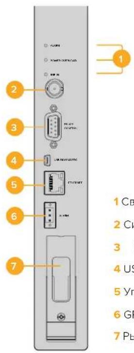
1 CBeToIIOHbIe INHdIKaTOpbl COCTOHHN
2 CnHxpoBxOa
3 YnpaBHeHne KOMMyTaTopom uepe3 npT RS-422
4 USB 2.0
5 YnpabnEHeK KOMMyTaTOpom Yepe3 Ethernet
6 GPI dny cnHnHaun3aun
7PbivaxkO
CBeToIIOHbIe HnIkaTOpbl coCTOHNHa Universal Videohub
CBeToIOIbHbIe INDnKaTOpblc MapKnipOBkoI ALARM, POWER OVERLOAD n REF IN cnnykat Ira otOobpaKeHnTeKyuIero CoCToHnKOMMyTaunOHnMAtpUbI Blackmagic Universal Videohub 288 Crosspoint. Hxke nepeuNCHeBb Bo3MOXHbIEBapNaHTbl.
CBeToaNoA LARM KpacHoro 乙Beta
| ● | OFF Oushiok net. HopmaJIbHaj pa6ota. |
| ● | Bkn. CoSTOJHne oushiok. Дугай оushiok. ИспьAZYe npotOKoI Telnet dlya podKlIoUeHnK yCtpoiCTBy nПolyeHnKa oushiok. |
| ●1 | ODNo MURAHne CoSTOJHne oushiok. OTka3 BeHTINJaTopa. |
| ●3 | Tpr MURAHnCoSTOJHne oushiok. OTcyTCTByeT pe3eRbHoe nITaHne. |
CBeToaNoD POWER OVERLOAD KpacHoro UBaTa
CBeToaIOA LARM KpaChoro UBaTa
YctaHOBka nHTeppeiChbIX nIaT
Yctanobka nlaTb Universal Videohub SDI Interface nn Universal Videohub Optical Interface He Tpe6yET CneuaJIbHbIX HABIKOB N BblONHЯETcOINHaKOBbIM OpbazOM B 06oix cnyaX.
1 Bo3mTe nIaty BepTnKaIbHo, yTO6bl IeHTnHcIpyUoI cBETOIOu HaxOaINcBaBepxy. CBETOIOu BBIJIaNT kA Ke60JIbUoe OTBepCTne CIEBa OT BepXHero pa3bema.
2 Octopoxho yctahOBInTe nnaty no HanpaBnIoum, Yto6bI OHa BOwna Do ynpa B cnot PCHa MaTePNHcKo nIate. C nMOuBIO OTBeTKn PoZidriv (pa3Mep 2) zakpyTne HntepFeiChHyo nnaty Ha Kopnyce Universal Videohub.
Iopno6Hee o KOMnoHentax dnia KOMMyTaTopa Universal Videohub cm. pa3dneIb «INTepeHcHbIe SDI-nnataB» n «INTepeHcHbIe nataIb dnia Universal Videohub>.
YctaHOBka nlaTbI nHTaHn Universal Videohub 450W Power Card
Плata петань Universal Videohub 450W Power Card nmeet trn cnIObIx pa3bema, kOTOpBc cIyKAT IIN NOkIIouHEnI CTeBbIX aanTepOB COBOkyHoi MOUHocTbIO Do 450 Bt. 3Ta pIaTO obecneuBaET AheprochabxekHe NOnHOCTbIO OCHauEHHoro KOMMyTaTopa Universal Videohub 72 C NOMOsbIO DByx aanTepOB.
TpTei aanTep No3BOJnEaBtOMaTHueckn BBOINb pe3epB Cnyae c6oHa OHom n3 yKe IcNoJIb3yEmbIX NCTOCHIKOB.
1Y6eNTecbBTOM,TOcTeBOI aanTep OTKIOUeH OT IcTOuHnKa 3HepeOCHa6KeHna.
2 Pacnojoknte nlaty nitaHnra TaKIM o6pa3OM, yTo6bl MapknipobKa MAIN POWER HaxoDnlaCb BBepxv.
3 YctahOBHTe nIaTy nITAHnB COOTBeTCTByIOuN Cnot Ha MaTePNHcKo IIATE. C nOmoUbO OTBeptKn Pozidriv (pa3MeP 2) 3akpyTnte nIaTy nITAHn DByM BINTAMN.
4 Поблочи тpr сеовьх щаantepa Universal Videohub 150W Power Supply.
EcnHyKHO CHTb Nn3aMeHNtB PnATy NnTAHn, ChaHaN aOKnIOUHTe 3HeprochA6KeHne nOTcoeHNHTe BCE cTeBBie aanTepbl.
Ecnn KOMMyTatop Universal Videohub 72 3anonHe HInTepeHcBIMn nIaTaMn He noNHOctbIO, dnerero nHTAHMOXET XBaNTb ONDHO cTeBO r aAnTepa MoUHocTbIO 150 Bt. B 3om clyae BTOPOAaANTep peKOMeHdyETc NcNoB3OBA Tb dNr ABOTMaTHueCKORo BBODa pe3epBa. PnTakOn KOHfYpauuNN BInONHHTe DeiCTBn B ONCAHHOM HNXe nopAKe.
1BpeMeHHO OTKIOHHTe BTOPOI CTeBOI aanTep n npOBepbTe COCToHne CBToIOHa POwER OVERLOAD Ha KOMMyTAUHOHHOI MaTPnue IocNe yCTaHOBN INTEpFeINCHbIX nIaT.
2Ecn OH ropnt, HxKHO do6abNTb aadantep 150 Bt mnn n3BneHcckoNko nlat, Tto6bl octaIbHbIe NOyuaJIu DOCTaTOHoe NITAHHe.
3ПослпроверксCBetoДиОДA POWER OVERLOAD BHOБь IOДКЛЮHTe BTOPOI cTeBоI aanTep.
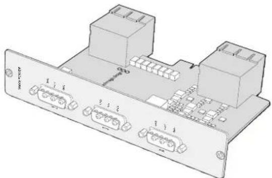
Pnaty nntaHr Universal Videohub 450W Power Card moxno NOKIOCHITK TpeM CetEBIM daNTepam MOHOCbIO no 150 BT
Ia 630ka3HO paObTu nHTAHn Heo6xOUMo MOHOCn peKOMeHdyetcN oDKIOuHTB N BcERda NCNoJIb3OBaTb Tpu CTeBBIX aadTepa npn IIO6oKOM6Haun yCTaHOBNEHHbIX PNaT.
Ecnn cetebo anapntep Hxkno ydaHnB nnn 3aMeHnT B TO Bpem, KOrDa KOMMyTaOp Universal Videohub 72 pa6otaert, otknouhnte 3heprochabxkeHne ToIbko dna cootbetCTByoero aanTepa n coxpanite ero noaay ha octaIbHbe. N3BnKeNTe cnloBOu shyp IEC, otKpyTtE BNHTb n oToeunHte cetebo anantep ot nataHnUniversal Videohub 450W Power Card.
Iop3dpabnem! KommyTaTop Universal Videohub 72 roTob K pa6oTe.
HntepeienchbIe SDI-nlaTbi
INTEPfechBle SDI-NTaTbIMeOT noYtebpe BxOda SDI n BixOda SDI, a TaKke npT dJa Ka6eJ Universal Videohub Deck Control Cable. Bce pa3bEmbl SDI noDepknaBoT abTomatueckoe onpeHene FopMata (SD, HD nn 3G-SDI), a Ha BixOde BblONnEeTc pereHepaunCnHaJ. JInHeKa Universal Videohub obecneuBaet odHOBPemEHHyo MapWpytn3auNIO BnJeO B 2K, HD, SD n DVB-ASl. INTEPfechBle SDI-NTaTbMOxHO yCTaHOBnTB BO BpEMpa60tBJ KOMMyTaTopa, nocNe Yero OHn cTAHOBnTc MFOBOeHHNO DOCTynHbIMn dJa NcNoIb3OBaHry. OTKnIOUaTb n CHOBA BKIOUaTb yCTpoiCTBO He HyXHo. IJa yCTaHOBKn pa3NIuHbIX NNat Notpe6yETc OTBeptka Pozidriv (pa3Mepe1 n 2).
KOMMyTatop Universal Videohub no3B0n8ET nCNoB3OBaBb Dba Tnna INHTepfchbix SDI-nlat.
- Pfntata Universal Videohub SDI Interface c BNC-pa3bemamn.
- Плara Universal Videohub Optical Fiber Interface co CTaHdApTHbIMN SFP-MOyIaMn (Длнаньгы 1310 NMдяпетачсигнад).Кждь мodyль осанцeh pa3beMOM LC дяпдключеня ODHOMODOBORKa6eЯ.
Bb6op nCTouHnKOB npneMHnKOB cnHaJa
Videohub Master Control Pro no3B0n8et 6bIcTpo BBbIpaTb IcTOUHKn n npneMHNK cnHana, a TaKke MeHrTa HApBaJIeHne MapuPyTu3aun C NOMOUsbIO NOnb3OBaTeNbCKnx RaNbIKOB nn NyTeM npAmoro BBOda HOMepa npTa.
Videohub Master Control Pro pa6otaert no taKOMy Je npHcunny, KaK IIObA npyra naHb ynpaBHeHn KOMMyTaTOPoM.
1Haxmnte KhoNky DEST, tO6bI oTo6pa3ntb Ha KK-dncnnee npneMHNK cnHana. NcnoB3yTe KhoNk nn Kpyrnyo pyky, tO6bI nepeTn K HyxHOMy npneMHKy.
2Haknte KhoNky TAKE nI noTbePckdHeNy BbOpa.
3HaxMITE KJIaBnSy RC NcnoIb3yIte KhoNkN nn KpyIyIO pyky, YTO6bl N3MeHITb NCTOHHK CnHaJa.
4HaxMMTE KHOKNY TAKE, YTO6bl NOITBepNTb N3MeHHe HAnpaBHeHn MapwpyTN3aUN.
Bb6op yctpoCTB BBOOM Homepa npTa Ha Videohub
Ecn Ha Videohub coxpanenbOpunHaIbHbIe npBk Bcx SDI-nHepcncob n nopTob
nCTaHIOHOYnpaBHeN,ImMeHNt HappaBHeNme MappTy3auM MoXHO nPoCTbIM BBOOM
Homepa npTa. Tako cnooc yckoparet paOty, OHaKo B ATOM clyuae HyxHo NOMHTb HymepaH
pa3bEmOB nn 3HaTb, Kaoe obopydOBaHne noKnUoyeHO K kaxdomy npTy Ha Videohub.
1Haxmte KhoNky DEST. Pone npneMnka cnHana Ha KK-dncnnee 6ydt BbIeJeHO CINHM cBETOM.
2EcnKOMMyTaOp Videohub IMeet npT RS-422 dny ydaJIeHHoro ynpaBHeHnna, Haxmaite KhoIky LEVEL do tex nop, noka He nepeiDeTe K hJxHOMy ypoBHO. B npotINbHOM cIyae nponyctnte 3OT war.
3IcnoIb3yK HONK CnΦpamB, BBeNTe HOMep npTa IJI npHemNka cnHaJ. PnHaxaTIN KxJaA KHONKa Mrraet 30JOTNCbIM CBeTOM OOnH pa3. PnHmHK 6yDet NOKa3AH Ha KK-dncnnee.Bcnyae oun6Kn HaxMITE CLEAR IN 3aHOBO BBeNTe HOMep npTa.
Hakmtke KhoNky SRC. Ione nctouHka cunHa ha KK-dncnnee 6ydt BdyIeHo CINHM ZEBOTM.
5NcnoIb3yKHOJIKN CUNΦpAMn, BBeIe NTHe HOpE npTa IINCTOCHNka CnHana. PIn HaxaTN KAKDaA KHONKa Mmraet 6eBIM UCBETOM OOnH pa3. NCTOCHNk 6ydt NOKa3AH Ha KK-dncnnee.B Cnyae Oun6Kn HaxMITE CLEAR n 3aHOBo BBeIe NTHe HOpE npTa.
6Khonnka TAKE 6ydt MraTb KpaChbIM CBetOM Do noDTHBepXdHnHO HOBOra HapBaIeHnMapuPytn3aun. Nocne ee Haxatna OHO 6ydt MrHOBeHNO n3MeHeo. IJIr OTMeHb HaxmteCLEAR.B 3tOM cnyae HapBaIeHne octaHcTe npexHM. NaHeb Videohub Master ControlBO3BpaAaETcB PexM OxndaHnA, a Ha XX-dncnnee oToobpaxaetcNoceJeHnAnpaBLeHne MapuPytn3aun.
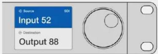
EcnHa Videohub coxpanHebOpunHahBhIe npblk Bcex SDI-nteppecoB n nopTob dctaHnOHHO npabEnHn3MeHHT happBeHne MapuPytnaM MoKHO npocTbIM BBODOM Homepa npTa. BtOM nPmpe HxMNTe KhoNky DEST n BBeDite Home8 84.Taem HxMNTe KhoNky SRC n BBeDite HomeP 52.VcnoBbYte KhoNky TAKE, YO6blnDbepdtb N3MeHeHne HappaBHeHnMappytnaAin.
Bb6op yctpoiCTB c nOmoIbu KpyrIou pyuKn
He3aBnCmO OTO, HAcTPOeHb IINI Het NOJIb3OBaTeNbCKNe JApJIbIKI dIe NOpTOB KOMMyTaTopa Videohub, INPocMOTpeTB INCTOChNIKI INPiEhMNIKI CNHaIa BCERda MOXHO C NOMOuBIO KpyrIo pyuKn. 3To cAmbl MeJIneHHbI cnOCo6 pa60tbl, ODAKO OH N03BOJraRyBnDeTB BCE IOCTYnHoe ObopdyoBaHne I INx pa3BeMbI.
1 HaxMnte KhoNky DEST. Ione npHemnHa cunHana Ha KK-dncnnee 6yDenBbDeneHO CnHM UBeTOM.
2Ecn KOMMyTaOp Videohub nMeet npT RS-422 dny ydaJIeHHoro ynpaBHeHn, HaxmAJte KhoNky LEVEL do tex nop, noka He nepeJdeTe K HyxHOMy ypoBn. B npOTuBHOM cIyuae nponyctnte 3OT war.
3IIOBepHnTe KpyTnyo pyKy Bnepei HnHa3aD nna nepexOa K HyxHOMy npHmNky CnHana. PnpemHnK 6ydt noka3aHa KK-dncnnee.
4HaxMnTe KhoNky SRC, yTo6bl OHa 3aIopenaCb 6eBIM cBETOM. Ione nCTouHnKa CnHana Ha KK-dncnnee 6yDet BbleneHO CNHM cBETOM.
5C nomoIbIO kpyrIoi npyKn nepeIInTe K HyxHOMy nCTOuHNy. IVctOHNk 6yDen t noKa3aHa KK-dicnnee.
6KhONka TAKE cTaNrET Mngatb KpaChbIM CEBOTM DO NOITBepKeHnHOBOr HOpapBHeHn MapuTy3aun. Nocne ee HaxaTnOHO 6ydet MRHOBeHHo n3MeHeHO. Jn r OTMeHb Haxmte CLEAR. B 3om cnuyae HapPabIeHne octaHcTe npexHm. NaHb Videohub Master Control Bo3BpaAaetcB pexm OxndaHn, a Ha KK-dncnnee oTo6paXaetcNoCneHnee HapPabIeHne MapuTy3aun.
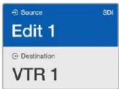
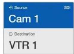
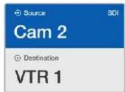
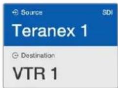
B 3OM npIMepe kpyrnyo pyky nCnoJb3yOt dI npocmotpa BceX nCTOHHOB, KOTOpBHe MOxHO H3aHHTb IIN pIneMnHa VTR 1 npn ypoBHeBOH hactpoKe SDI. Pnp ee nobopoTe nocneobatelho OTo6paxiaOTc HAnMeHOBaHn COOTBeCTByUoero O60pyoBaHn Dn8 o6IeYHn NOnCKA.
Bb6op yctpoiCTB c NOMOIO HacTpaNBAeMbIX KHOJOK IN KpyrnoI pyKn
Ecn npTb KOMMyTaOpa Videohub IMeHOT nObl30BaTeIbckne apIbIKn, HAcTpaIbAembie KHOKN KpyIyO pykU MOxHNOICNOLB3OBaTB COBMeCTHO IJI NONCKA NO COKpaUeHHOMY CNICKY NCTouHKnOB IN pInEMNHKO B CnHaJa. 3TO 6bICTpbN INHTyNTNBHO NOHHTbN CnOCo6, NOTOMY UTo KOINueCTBO yCTPOiCTB ORpAHuHeO, a NOMHtB HOMepa NOPOB He HyXHo. OH OcObeHNo yDoBeB Tex clyaJx, Korda npIbIKn npncBOeHbI NO TINY o6OpyDobAHn (HAnpIMep, VTR, Cam nn Mon).
1 Haxmte KhoNky DEST. Ione npemnHa cunHala Ha KK-dncnnee 6ydt BbIeJeHO CINHM UBeTOM.
2EcnKOMMyTaOp Videohub nMeet npT RS-422 dIyuaJIeHHoro ynpaBHeHn, HaxmAJTe KhoNky LEVEL do tex nop, noka He nepeiDeTe K HyxHOMy ypoBHO. B npOTNBom clyuae nponyctnte 3OT war.
3 Haxmnte KhoNky, KOtopa HactpoeHa Ira pa6Otb CyctpoiCTBaMn-npneMHkamn onpeJeHHO Tnna (HanpImep,VTR). OHa 3aTropTC30JOTNCbIM UBeTOM.
4NoBepHnTe KpyrIyIO pyuKBypeI nn HaaI npaepeoxa K HyxHMy npemHky CnHaI. B 3tOM npimepe Ha KK-dncnlee 6ydet oTo6paxatbcra VTR. B cnyae Oun6kn HaxMnte CLEAR n HauDnTe HyxHbI npemMHNK.
5 Haxmte KhoNky SRC. Ione nctouHnka cnHaHa KK-dncnnee 6ydt BbIeHeo CnHIM cBeTOM.
6Haxmte KhoNky, KOtopaa HactpoeHa dIpa60bI c NcToHnKaMn CnHaJa onpeJeHnHO Tna (HaipnMeP, nata 3axBaTa). OHa 3aROpntc 6BeMb UCBetom.
7NoBepHnTe KpyrIyIO pyKy BnepeI nnHa3aI nIe npexOda K HxhHomy NcToUHky CnHana. B ATOM npImepe Ha KK-dncIIee 6yET OTO6paXaTbCra IIATA 3axBaTA. B Cnyuae Oun6kn HaxMnTe CLEAR n Haundte HyxHbI npneMHNK.
8KhONka TAKE cTahet Mngatb KpaChbIM CBETOM Do noNTBepXdHnHO HOBOr HapBaJIeHnMapwpytn3aun. Nocne ee haxatna OHO 6ydt MRHOBeHNO n3MeHeNo. Ira otmeHbI HaxmTe CLEAR.B 3tOM cIyae HapBaJIeHne octaHcTc npexHm. PaneIb Videohub Master Control bepHcTc B pexm OxuaHn, a Ha XX-ducnnee 6ydt oTo6paxaTbc nocJeHne HapBaJIeHne Mapwpytn3aun.
Ecnn KhoNkA, HactpoeHHa nIpa6Oblc nctouHnKOM nI npMeMHNKOM CnHaIa, Mraet, Ho He 3aropaeTcR, ee Bb6op 3aboknpoBaH. TaKa rCtuaqna Bo3HnKaet B Tex cnyaax, Korda obopyoBaanHe o6o3NaueHo kak nCTouHnK nI npMeMHNK IIOBO He OTBeuayet KpntepnM Tekyuero yobHn. HanpImep, Kaempb ObuiHO He nCnoB3yOT dI npMeMa n3o6paXeHnA, a MOHTOpbl He cnJxat B kaeeCTbe nctouHnKOB. Kpome TOrO, 3Tu yctpoiCTBa He mEeot npTa RS-422. Pndpo6Hee cm. pa3d e O hactpoKe naHenn Videohub Master Control Pro.
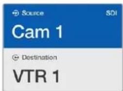
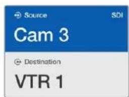
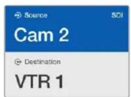
B daHOM npimepe haxkata KhoNc c noIb3oBaTeIbckm npblkOM Cam, noTOMy npnIOBOPTE kpyTOn pyKu TOnko Kamepb6dyT OTo6paKaTaBCa KAc NCTOHNK. Bnaorapr TOMy, yTO cnCOK o6OpyDobAHnOrpAHueH, moXHO b6CTpo HaiTN HyKHoe ycTPONCBO.
Bb6op yctpoiCTB c nOMoIbIO KHOJOK C uIΦpaMn I kpyrIo npyKn
EcnI npTbI KOMMyTatopa Videohub IMeOT noJIb3OBAteMbCKne apblkC HOMepAMN, KHOKNIK KpyrIyIO pyKu MOxHIO NCNoB3OBaTB COBMecTHO dIra NOUcKa NO COKpaueHHOMy CNNCKY ITOUHNKOB INPnEMHNKOB CnIHana. 3To 6bICTpbN INHTyNTNBHO NOHATbIN CNOCo6, NtOMy UTO KOInueCTBO yCTpoiCTB ORpaHnueHo, a NOMHtB HOMepA NOPTOB He HyxHO. OH OcoBeHHO yDObEN B TEX CnyaX, KOrDa eCtB rpynnOBbie apblkC hymepaueNe dIra ONpeDeHeHoro MecTa (HaNPIMep, ObopyDoBaHne B CTyDN N ^三 3 IMeet cIeDuOuIe Ne IeENTnΦHKaTOpby: VTR3, Edit 3, Cam 3A, Cam 3B, Mon 3A, Mon 3B n T. d.)
1Haxmte KhoNky DEST. Ione npneMnka CunHa nHa XX-dicnnee 6ydt BbleneHo CINHM UCBETOM.
2EcnKOMMyTaOp Videohub nMeet npT RS-422 dIydaJIeHHoro ynpaBHeHnra, HaxmaiTe KhoNky LEVEL do tex nop, noka He nepeiDeTe K HyxHOMy ypoBHIO. B npOTnBHom cIyae npOnyCTte 3OT war.
3NcnoJIb3yKHOIKN CnΦpAMn, BBeIeTe HOMep nOpTa IJn pInemHnKa CnHaJa (HanPIMep, 3d7 Studio 3).Ipn HaxaTIN Kaxda TaKaA KHONKa 6yDeT MmTaB 3OJOTNCbIM CBETOM.
4NoBepHnTe KpyIyU pyKu Bnepei IIN Hau3aI IJI nepexOda K HxhHOMy npnEMnky CnHaIa. B daHHOM npImepe Ha KK-dncnnee moXHO oTo6pa3ntb VTR 3, Edit 3, Mon 3A IIN Mon 3B. B cnYuae Oun6Kn Haxmnte CLEAR IN Bb6epnte npyroHomep npnEMnka.
5HaKMTe KhoNky SRC. Ione nctouHka cnHaIa Ha KK-ducnnee 6ydt BbIeNeHO CnHIM UBEtom.
6NcnoJIb3yK HONKc C uΦpAMn, BBeIte HOMep NOpTa dIa ITOUHka CNHaJa (HaNPIMep, 3dIg Studio 3).Pnp Haxatnn KkDaTakar KHONKa 6yDet MIRATb 6eBIM UBeTom.
7NoBepHnTe KpyIyU pyky Bnepei nn Ha3aI nI nepeXoJa K HxKHomy NCTOCHKy CnHa.
B daHHOM npImepe Ha KK-dncnnee moKHO oTo6pa3ntb VTR 3, Edit 3, Cam 3A nn Cam 3B.
B cnuyae Own6Kn HaxMnTe CLEAR IN Bbl6epTe dpYroH Homep NCTOHNka.
KhONka TAKE cTahet MURATb KpachbIM UBeTOM Do NOITBepXKeHnHO HOBOr HappaBHeHnMapuPyTHaun. Nocne ee haxatra OHO oy Det MRHOBeHNO 3MeHeNo. INaOTMeHbI Haxmte CLEAR.B 3tOM clyae HappaBHeHne ocTaHcTeC npexHm. PAneJIb Videohub Master Control bepHTcB pexm OxuaHnA, a Ha KK-ducnnee oTo6pa3ntc nocJeHne HappaBHeHne MapuPyTHaun.
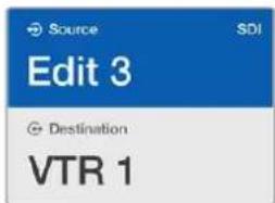
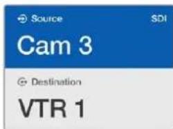
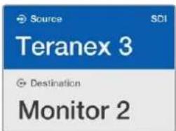
B ATOM npIMpe haxata KHONKa c uHPO3 3, noaTOMy npn nobOpote Kpyrnoi pyuHKHa XX-DncnIee 6dyT OTObpaXaTBcra TOLko Te NCTOCHNK, npblkKOTopbIX coepxat daHHyo UHpy. Korda cnCoc kOBOpYDoBaHNr orpaHnueH no KaKOMy-1nHO pnpAHAky (HaNPmep, Tohko TexHnka B CtydnN No 3), MoKHO bItpO HAnH NyHXo yCtpoNCTBO.
Bb6op yctpoiCTB c nOMOuHactpaBaembIX KHOIOK IN KOHOOK C uΦpamN
EcnnpbKOMmyatopa Videohub IMeHOT INHnBnUyAIBHbIe npblkC nmehamn HomepaMn, HactpanBaemble KHOKN KHOKN C uHpammoXHO NcNtB3OBaTb COBmecTHO dIpyMOrO BbOpapnTOChuHKnOB n npneMHKnOB CNHaJa. 3TO OueHb 6bICTpbN nHTyNTBHO NOHRTbN CNOco6, NOTOMy TTO NOCK NO CNICKY OOBpyoBaHn He Tpebyetc: HxHO BCero NINb NOMHTb KOINCTBO eHNHnDnKaxDoRTo BnDa TexHKn (HaPnPmep, DBA BnDeomarHtofoHa N yETbipe MOHtopa).
Oh o6o6eHNo yO6eB Tex cnyaX, KOrDa obOpdyoBaHne IMeET rIpbIK C mHeAMn HOMepaMn (Haipmep, VTR 01, VTR 02, Cam 01, Cam 02, Cam 03, Mon 01, Mon 02, Mon 03 n Mon 04).
1 HaXMMTE KhoNky DEST. Ione npneMHnka CnHaHa Na KK-dncnnee 6ydt BbIeHeo CnHm UBeTOM.
2EcnKOMmyTatop Videohub nmeet RS-422 dIy ydaJIeHOro ynpaBHeHn, HaxmamTe KhoNky LEVEL do tex nop, noka He nepeiDeTe K HyxHOMy ypoBHIO. B npotNBHom cnyae nponyctnte 3OT war.
3 Haxmnte KhoNky, KOtopa HactpoeHa Ia pa6oIc yctpoICTbAMn-tpneMHkamn onpeJeHHO Tnna (HanpImep,VTR).OHa 3arOpntc 30JOTNCbIM cBeTom.
4VcnoIb3yKhONkCuΦpAMn,BBeDnteHOMepIpyneMnKa CnHaNa(HanpIMep,07dN VTR 07).Pn Haxatnn KaxdaTakay KHONKa 6ydt MrratB 3OJNTCTbIM cBETOM.
5 Haxmte KhoNky SRC. Ione nctouHnka cnHana Ha KK-dncnnee 6ydt BbIeHeo CnHIM CBetOM.
6Haxmte KhoNky, Kotopar hactpoeHa Iny paobToBIC NCTOCHKAMC CnHnla onpeJeHHoro Tnna (Ha npimep, nata 3axBaTata). Oha 3arOpntc 6bem UBeTom.
7nOb3yK HONK CnΦpAMBVEHNTe HOpE nCTouHnKa CNHana (HaPmep, 03 nnaTbI 3axBaTe Edit 03).Pi np Haxatnn KaxdAra TaKa R KOnka Byet Mrrt BEBIM CBETOM.
KhONka TAKE cTaHET MIRATb KpaCHbIM CBETOM DO NOITBepXJdEHnHO HOBOr HAnpaBHeHHaMappTyI3aUH. Iocne ee Haxatra OHO 6ydet MRHOBeHNO N3MeHcO. JInr OTMeHbI HaxMITE CLEAR.B 3tOM Clyuae HappaBHeHne octaHTc npexHM. NaHbV Videohub Master Control BepHeTcB pexm OxuaHnA, a Ha XX-KinCnnee oTo6pa3ntc noCneJeHnAnpaBHeHne MappTyI3aUH.
Ecnn KhoNkA, HactpoeHHa nIpa6Oblc nCTouHnKOM nI npMeMHNKOM CnHaIa, Mrraet, Ho He 3aropaetc, ee Bb6op 3abIOKnpoBaH. TaKa cntyaunr Bo3HnKaet B Tex clyuax, Korda obopyoBaHne He o60haeNo kac nCTouHnK nI npMeMHNK IIOo He OTBeuaet KpntepnM Tekyuero yobHn. Hanpimep, Kaembi O6buH No He NCnoB3yOT dIra npMeMa N3o6paXeHn, a MOHTOpbl He cnJxat B kaueCTbe nCTouHnKOB. Kpome TOrO, 3TN yCTpoiCTBa He nmeIoT npota RS-422. Pndpo6Hee cm. cekuiIO «Co3dahne JapbIKOB KhoNok» pa3dena «HaCtpoika naheIn Videohub Master Control Pro>.
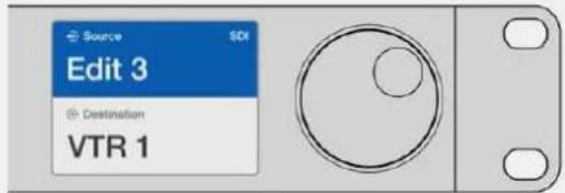
PpeNoIoxm,obopyoBaHne Edit 3 n VTR1 HxNHO Bb6paTbKaK NcToUHK nPiemMnK CnHaIa COOTBeCTBHeHn. HanpaBHeHne MapwpyTu3aun MOxHO 3aATbHapmyo 6e3 o6paueHnK cnncky. HaxMITE DEST,3aTeM KhoNky, HacptocHHyo dJa paoTb C BuDEOMarHTofoHAMn,3aTeM 1.B NOle pnpemHnKa 6ydt OTo6paxaTbCyrV 1.HaxMITE SRC,3aTeM KhoNky, HacptoeHHyo dJa paoTb C TexHHKO JMOrMA TOnkA bJeEO,3aTeM 3.B NOle NcTOOHHa Ka 6ydt OTo6paxaTbC8 Edit 3.HaxMITE KhoNkyTAKE,yTo6bJnoTBePdntb N3MeHeHne HappaBHeHn Ma7pyTu3aun.
KK-dncnneuHaayabhaCtpaHua
BcTpoeHHbIK-KIcNneOecneHbAet 6bICTpbIN HHTyNTNBHO NOHrTHbIN cnoOCoPpTa IN3MeHeHnHaCTpoE, PIn BkHoueHm MoEn BlaKmagic MultiView 16 Ha 3kpAne No yMOnuHnIO NOBbIeTcH aHaJIbHra CtpaHnua. Ha He OTo6paJAtCp npBBeEHhbe HnKe HAcTpoKn.
ΦopMaT HD-BnDeo Ha BbIXOe
HΦopMaŋoΦopMaTe HD-BnIeO (1080i/59,94 nIIN 1080i/50) Ha BbIXoJax HD-SDI oTo6paxaetcB Nebom BepxHem yTny.
AynOBXoA
Данньл napametр haxountc pyanom c φopmatom HD-buodeo. ON noka3bIbaet, kakoi SDI-Bxod nCnoNb3yETc dny BHepeHn 3Byka b HDMi- n SDI-cunHaJIb dny MHOOROKOHORO MOHITOpnHra.
KoHpypaunMHOOROKOHOROMHTOPnHa
3TOT npametp noka3bIbaert paonoloxeHne IcnoIb3yEmbIX OKOH. ERO MOXHO ONTNIMNIPOBaTB NOd HNCIO NODKIIIOUeHHbIX BXOIOB.
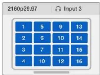
No ymonuHa KK-dncnnee
naHennynpaBneHnroOTo6paxaetcra
haabhaCtpaHua.Ecnn
HaCTpoKnyM3MeHn,BCPhyTbca
HaAty CtpaHnMoXHO HaxKaTNEM
KHonkN MENU.
KhONKn ynpabBHeHn

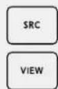
SRC (NCTOCHNK) N VIEW (OKHO)
Haxmte KhoNk SRC N VIEW, yTo6bl OTKpbItb HactpoKn NCTOCHNKOB N OKOH.3n KhoNk No3BOJIoT Bbl6paTb NCTOCHK BXODaIeRO CnHaJa DnA MOHTOpHHra.
1Y06bI OTKpbITb 3KpaH Bb6opa OKOH, HaxMNTe KONky VIEW. AKTNBnpyerca pa3dien View B HNXHe nolOBnHe KK-dncnJe.
2 Haxmte KhoNy C u npoi, YTObblb6paTb XeIaemoe OKHO.3Ty OepauHIO MoxHo TaKHe npOeIaNb C nOMoUbKO pyrIOn pUKN. DnA NOITBepXdEHN HAcTPOIN HaxmTe SET.
3 Haxmte KhoNky SRC. AKnBpyeTcra pa3deI Source B BepxHn nooBHe KK-dncnne.
4 Haxmnte KhoNky C uHpOy, YTo6bI Bb6paTb XeHaemBxOa. PiocMoTeB BXoDbHa DnCnlee MoXHO TaKKe C NOMOuB KpyrIo pyuKn. Ecn npblk INOIOB 6bln N3MeHeHbI, OHn 6dyT OTo6paKaTbC B BepxHeINIOOBnE DnCnJIe.
5 Haxmnte KhoNky SET, yTo6bI noTBPentb cdeNaHbB BbOp.

SOLO (Cono)
Дя MOHITOPINHRA B NOHOKpaHHOM pexmte HaxmTe KhoNky SOLO. HaxmTe KhoNky C uipoi, YTObI BbIpaTb Jenaemoe OKHO. 3Ty onepauuMOxHo TAKxe npoDetaB c NOMOcIbO Kpyrno pyuKn. Jnra BO3Bpata K MHOOROKOHOMy pexmMy HaxmTe SOLO eue pa3.

SET(YctaHOBntb)
Hakmte KhoNkY SET, yTo6bl noTBePnTBbB6Op. Pnp HaxaTN KhoNkNoB bIbpaHHbIM npametpom noBnTcpeTa, a KhoNk SET n MENU 6ydyT MInarb. Yto6bl noTBePnTBnMeHeHne, Haxmte SET eue pa3.

MENU (MeHIO)
HaxMTe KhoNky MENU, yTo6bI oTkpblb HacptponK. Nocne BHeceHHn3MeHnHaXMMTe 3Ty KhoNky CHOba, yTo6bI BepHybcra Ha HauaJIbHyIO CTpaHNUy.

KhONkncuΦpamn
KHOKN C uΦpAMN NcNOB3yOTcIa Bb6opa NCTOCHNka NOKHa BCOTBETCTBYIOUX HAcTPOKax.
C nOMOJIbIO 3nIX KHOHONK TAKKe BbIbIpaIOT SDI-pa3beM dIra aydIOBxOJa.
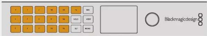

SRC (NctouhMK), VIEW (Okho) n SET (YctahOBtB)

HaKMMTe KhoNk SRC N VIEW Ha naneHn ynpaBHeHn, YTObIOTKpbITb HAcTpoiKn NCTOCHNKOB NOKOH.ДЯ BHeCEHn N3MeHHeH NcNoJIb3yIte KHOKN C cHpaMn NN KpyrIyIO pyky, a 3aTEM HaKMMTe SET dIe NOdTBePxxDeHn.

HacpoiKn, B KOtOpBle BHocTcR KOppeKTIPOBKn, BbIeJIaIOTcRa Ha 3kpaHe. Bce doabneHHbIe BXoam npblkn 6dyT OTo6paKaTbc DOJKNbIM o6pa3OM.
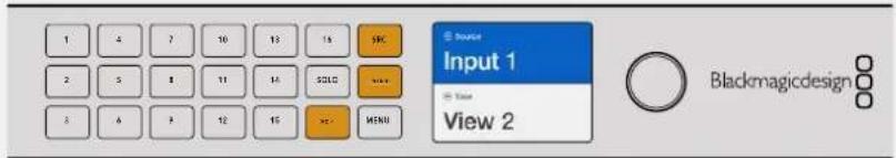

SOLO (Coi) MENU (MeHIO)

HaKmte KhoNky SOLO, TTo6bI nepeTn B noHOnKaPaHHb peXIM.
KhONka MENUs Cnyknt dnnpepexoJa K hactpoiKaM, a TaKke dJa BO3BpaueHna Ha HauaJIbHyIO CTpaHNUy.
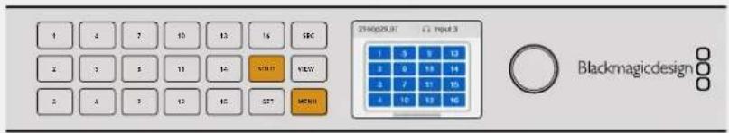
GPI and Tally Interface
Blackmagic Design GPI and Tally Interface - docynhoe no uehe pewehne dna Mhorokamephoro npou3bOcTba, KOrJa npu nCnOJIb3OBaHmMoUyra CCU Heo6xOJMo BO BvIBeCTn OIN H3 KOHTpOJIpyEmbIX BnDEONOTOKOB Ha MOHITOp. YcToPcTBO IMeET NIO BOCEM IporpaMMpyEmbIX BXOJHbIX N BbIXoNDbIX KOHTaKTOB.
Pn onpeenHHom HapabHeHm Mappytn3aun BxObl HnpabTnoT ue3 npT Ethernet Ha KOMMyTaTOp Videohub KomAdbb BbIBeCt n3o6paXeHne C bblbpaHHo KaMepbHa MOHTop, a BbIXOdbpepaT Tally-cirHaHa KaMepb nn Dpyrye yctpoCTBa.

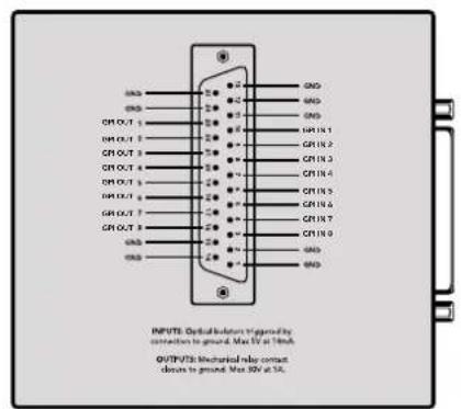
GPI and Tally Interface Cxema paonai npa3ema DB25
Pn co3aHnn c06CTBeHHoro Ka6eIy IcNoJIb3yIte IaIarpAMMy Ha 06paTHo CTOpOHe yCTpoiCtBa.
Повробkee о HabстpoIKE peшеня GPI and Tally Interface c nOMOsbko yTINITbI Blackmagic Videohub Setup cm. pa3dEN «ПО Blackmagic Videohub».
ПО Blackmagic Videohub
PpncBcOeHn npbka nctouHnky nnpneMHnky cnHaia
1UeKHTne no COOTBeTCTByIOUeMy TEKCTOBOMY NOIO.
23aaine HOBoe mHaKmTe KnaBnUy BBOda Ha KnaBnA type KOMnbIorepa dna nepexoJa cneDykuEMy noHIO nn npocTo eKnHe no HeMy, yTObI erO BBipatb.
3Pocne BBOda Heo6xOIMOn HnHOpMaun HaxMnte Save.
Baxho npncboNTb npbIK Taqim 6pa30m, qTO6bl OH COBnaadn C 6Oo3haeHnM KHOIOK nTOKOB Ha yctpoictBe, Hapnpmep DECK - nra pekopdepob,a MON - nra MOHTopoB. PekomeHyETcBAHOCNTb N3MeHeHn OHOBPemHn DnRA oEcnpeHn IX COOTBETCTBnA pyr dpyry. NoDpObeHee cm. pa3dEn «Do6aBneHne npbIKOB Ha KHONKn
COBET.ФункционлфпьтрашиTekста при paobote c peшенm Videohub cyBCTBNTeHEN K peRnCTpy.
Iocne npncboeHn npbIKOB nctouHKam n pniemHKam cnHaJn Xn TaKke MOxHO COXpaHnTb B KaueCTBe HaOba. TOrda, eCNI B 6dyuS cNPOBITc HcO6xoDMOCt b N3MeHeHn RaIbIKOB BO Bpemr pa60bHn HAD HObIM IpoEKTOM, MOxHO NCIOJIb3OBAbTa paHee COxpaHEHHhe HAcTPOKn.
Popraok coxpanenHa6opa npbIKOB
1HaxmTe Ha 3aOK wectepeHKn B HxHeN cekn Inputs nN Outputs nBb6epnte Save Label Set.
23aainmfaanBbepnmeMeToIero coxpanenHaKMTe Save.
PopjdoK 3aqrpy3kn Ha6bopa npblkOB
1HaxMnte Ha 3Naoyok weCtepeHKn B HxKHe Nactn cekuN Inputs nN Outputs, a 3aTeM Bb6epute Load Label Set.
2UeKHTe no paHee coXpaHEnHOMy Habopy npbIKOB n HaxMITE Open.
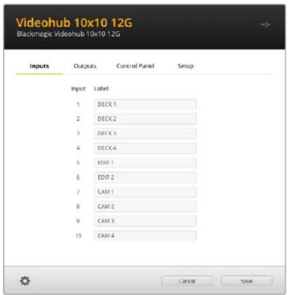
PIMMEAHNE. CnEuyETOTMeNTb, yTo Heo3MOXHO 13MeHHTbApbIKHa cepBepe IP Videohub, nockolkynx HaBaHHa NoCTyNaIOT C noDKIOUeHHoro BnuDeoo6OpydoBaHHa DaHHbe npblkx xpaHtca Ha noCoEOHNHeHHOM KOMMyTaTope Videohub n OTO6paxiaOTc TaKke Ha dpyrnx NaHEnx ynpabNeHHa IokalbHoCetN.
BbI6oppeXIMa npMOro nepeKIOueHmexy BbIXOaMn
Ha BknaIke Outputs pIaOM c o6o3haeHnem KaJdoRo bIbXOa MoXHO noCTaBHTb fIaXOK, KOtOpB IIO3BOINr 3aIaTb dIy IIO6Oro n3 HIX peKIM npMOrO nepeKIOUeHn. Iocne eToro HAnpaBHeHne MapwpyTu3aun Byet DoCTynHO dIy IImMeHHeN 6e3 DoONHHTelbHoro HaxKaTHN KhoNk TAKc C cIeIbNO noITBePckDeHn OepaCNI.
Pexnnpmno nppeeknuehen moxho Bb6paT nO tneBbHx npemHko cHana n60 BKIOHTb nN OTKIOHTb dN BCEx BbIXoDB yCTpoIcTB c nomoubio onu All On n All Off.
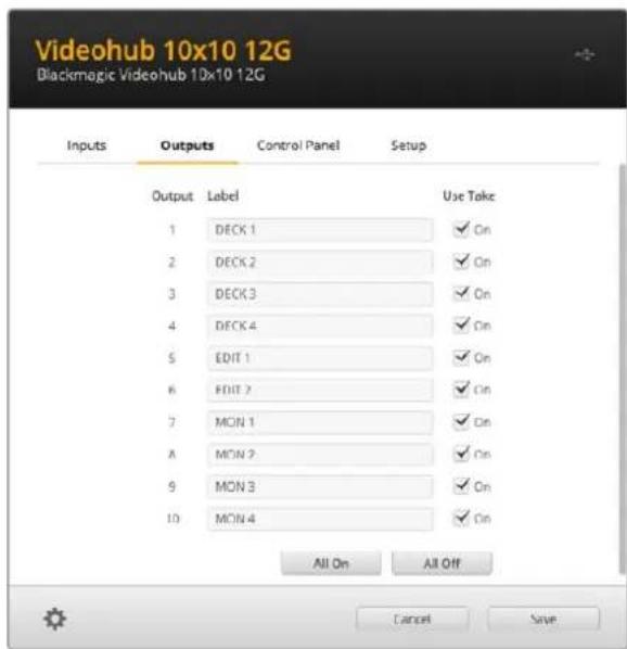
Peknnpmo nepeknoyeHn no3BnoT nmeHn HapnbHeHne Mapuyn3aun be3 nCnoJb3oBAHHn KhoNn TAKE
C03dahne MaKpOKOMaHd
Ha BknaKe Control Panel MoXHO 3aDaTb KHONK MaKPOKOMaHn Ha3HaHTb IM COOTBETCTByUOuNE FyHKuN.
Haxmte nepetae cnaep Number of macros BnpaB no daobanehra Taknx anemetob nIIN BnEo dnn Ix ydaeneHn. No mepe nx noaBneHn nporpaMMbIe KhoNk Ha ctpaHnue yTnNTb6ydt 3aropatcbc 6ebim CBTOM.
PopraokHa3HaueHmMaKpOKoMaHdbi
1Haxmte Ha 6eIyK hONky B cekuB Button Mapping. NoI He NnOBHTc MeHIO co CTpOKAMN oA do P. KaKdA n3 Hnx npedctablaet coboi otJeIbHyIO onepaunIO no I3MeHeHIO HanpaBHeHn MapupTytnaun.
2B MeHIO Source cTpOKn A yKaXnTe nCTOuHKn BXoJaIero CnHaNa, a 3aTeM Bbl6epuTe dna Hero npneMHNK.
3HaKmTe Save.
Ha3haueHHe MaKpOKoMaHdbI 3aBepWeHo.
MaKpOKOMaHda,Ha3NaueHHa corIacHO OINcAHbIM BIIe HNCTpyKunm, COOTBeTCTByET ODHOMy DeiCTBnIO MapuTy3aun, ODAKO MOxHO yBENuHTb KOINcECTBO ONepaun, BInONHReMbx npapannelbHo. HanpImep, npnpabote HaipnoekTom, KOTOpBn npednonaraet CNOxHyo nocneObaTeNbHOCb NMeHeHn, dJe ee 3anyCa DoCTaTOUHO eINHCTBEHHOH KNONK!
IaKTHBaunMaKpOKoMaHDbI HaxMITE COOTBeTCTByIOUy KONky Ha naHEn ynpabHeNn I nCnoB3ynte KnaBnuY TAKE nn noTBePxxDeHn Oepauu.
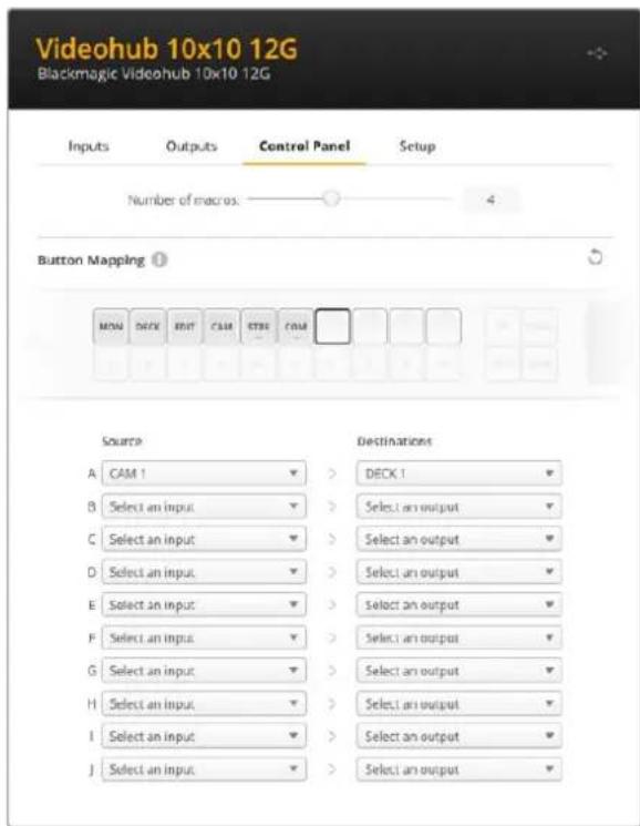
MaKpOKOMHdbI No3BOJNHT BbINONHbT HeCKOJIbKO N3MeHeHH HAnpBHeHHaMapuPyTu3aUIn ONDOBpeMeHHO
Ha3haeHne KhoNok
KhoNc c npbikamn Ha naHEn ynpablenenr Videohub nCnoB3yOT dIra Bb6oparpynn
obopyoBaHn npu nImeHn HnpaBHeHn Mapwpytn3aun. Hnnpimep, npaPbote Ctpem
pekopdepamn HyperDeck co Bxodamn DECK 1, DECK 2 n DECK 3 moXHO haxaTb KnaBnuy DECK,
tObbl cokpatntb cnCOK oCnueHn ToIbKO do 3TNX nCTOuyHKOB CnHaNa, a 3aTeM npmehnTb
kpyrnypoyykny noncka nn KnaBnC COOTBetCTByIOUmmu NcPpOBbIMn Oo03aueHnMn Dnra
OKOHaTeJIbHO rBb6opa.TakOn fynKNoHAnOCo6eHNO nOle3eBO BpeMa nCNoB3OBaHn
kpyhbxMoJeVideohub c 6oJbShm KOnueCTBOM nOdkNoueHHo annapatypbl.
Ecnn KhoNke 6bIcTporo DocTyna HxHNO pncBOnTb HOBbl npblk, BaxHo npaPnEnbHO n3MeHHTb COOTBeTCTByIOoee Oo3NaueHne Iy Phnuecko KnabuHa Ha yctpoiCTBE. NpOboHee CM. pa3dien «DobabNeHne npblkoB Ha KhoNkn
PnpdoK npncBcOeHnrypIbka KhoNke notoKa
1UeKHTe no KHOKe NOtOKa HBeTe dIy Hee HyKHe Oo3HaueHne B TeKCTOBOM nOJe. BaxHo, yTo6bI OHO COOTBeTcBOBaNo rApIbKaM BXoOBo N BixOoB. HanpImep, ecn peKOpIepbHyPERDeck nOmeHb KaK DECK 1, DECK 2 n DECK 3, nx 6ydt pacno3HaabaT b KlaBnwa c npbikom "DECK".
2HaxmTe Save.
PpO6Hee 03TOM cm. pa3dien o donoONHHTeNbHbIX 3JeMeHTax ynpaBneHnA.
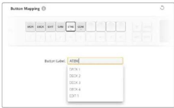
BBeHNTe HOBoe 6o3aueHne dN KhoNKn noToKa n HaxMntc Save
OchOBhIe HacTpoiKN
Ha BknaIke Setup moKHO yka3aTb hM KOMMyTaTopa Videohub, yTo6bl 3aTeM nHeHTnHIpOBaTb yCtpoNCTBO B cTeN. BBeNTe ero B COOTBeTCTBHyUcEM nOe N HaxMMTe KHNKy Set.
YTO6bI N3MeHNTB R3bIK INTEPpeCa, nCnOJIb3yEmoRo Ha KK-dIcNIIee yCTpoIcTBA Videohub, BbIePeITe HyxHyIO onuIO B CTpOke Language I HaxMITE Save.
PekomehdyetcnaobpaatbceKnoCneHneBepcnnypkoBOcTBaNo3Knnyatauun,KOTOPaIocTyHa BueHTpe noDnepkKn Blackmagic Design Ha cTpaHnue www.blackmagicdesign.com/ru/support.
Onzna Video monitoring
Korda daHnag onuagkTbnpoBaHa, B pexnme npedBapntelhoro npocmotpa Ha KK-dncnnne 6yET BbBOIDNTBCa NtOCHN K3O6paKeHn, CNHAn KOtOpOro B HactoI MmEHT nepedaetc H a BB6paHHn npemMHn.
Kpome TOrO, INxOJHoe BIndeo MoXHO npOBepNTIpeD IN3MeHeHEm HapPabJIeHn MapuTyN3aun. TaK, npOKpyTKc c nOmoU bIO KpyrIoI pyUKN nonCKa no3BOJraT Bn3yAJIbHO y6eINtBcR B BblOpE HyXHOrO nOToka.
Дя OTКLOUHeHЯ pexmma npdBapntelbHoro npocMOTpa BndeO CHMITE phaXOK Video monitoring Ha BknaKe Setup. 3To nO3BOJNT BepHybcra K hauJIbHOI cTpaHnue Ha KK-dncnlee, KOtopa OTO6paxaet cAndaptThb IHTePfeC NCTOUYHka IN pniemHnka CnHana.
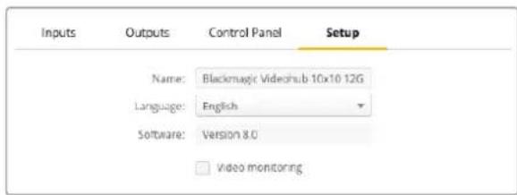
CHIMITE pIaKOK Iraonu Video monitoring,OTobI OKIOHITb peXIM IpeBapHTeBHorO npocMToPa Ira BVIDEO nCTOHHKA NpneMHNA CnHaHa Ha KK-dncnee
Network (CeTb)
Hn Hn Hn Hn Hn Hn Hn Hn Hn Hn Hn Hn Hn Hn Hn Hn Hn Hn Hn Hn Hn Hn Hn Hn Hn Hn Hn Hn Hn Hn Hn Hn Hn Hn Hn Hn Hn Hn Hn Hn Hn Hn Hn Hn Hn Hn Hn Hn Hn Hn Hn HH nnn nnn nnn nnn nnn nnn nnn nnn nnn nnn nnn nnn nnn nnn nnn nnn nnn nnn nnn nnn nnn nnn nnn nnn nnn nnn nnn nnn nnn nnn nnn nnn nnn nnn nnn nnn nnn nnn nnn nnn nnn nnn nnn nnn nnn nnn nnn nnn nnn nnn nann nn nann nn nann nn nann nn nann nn nann nn nann nn nann nn nann nn nann nn nann nn nann nn nann nn nann nn nann nn nann nn nann nn nann nn nann nn nann nn nann nn nann nn nann nn nann nn nann nn nann nn nann nn nann nn nann nn nann nn nann nn nann nn nann nn nann nn
Длг nx n3MeHn yctpoiCTBO VideohubdoJxHo 6bIb noKIOueHO K KomblTepy uepe3 nopT USB.
YTo6bI npedOBpAHTb ydaJIeHHoe aMmHnCTpnpoBaHne ycTpoCTBa, B HAcTpoKax
yTInITb Blackmagic Videohub Setup moXHO pa3peuNTb noIb3OBaTeJAM BHOCITb I3MeHeHnra
ToIbKO uee3 USB, BB6paB onUIO via USB.
Данные napametpbIMeIOT BaxHoe 3aueHne nIynpaBHeNIG KOMMyTaTopoM Videohub (Hanpimep, Universal Videohub 288) no cTeN C nOmoUIO NO Videohub Control INBHeHero annapathoro npbTa, taKOrO kAk Videohub Master Control Pro. Ioppo6Hee cm. pa3dE «ПоdkIoueHne komMyTaTopa Videohub K KommbIoTePhoN cTeN".
Reset (C6poc)
Khonka Factory Reset no3Bonaet ydaHtB BCE Ha3HaueHbIe MaKpOKOMaHdbI n npblk, a TaKke BOCCTaHabnBaET NcXoHbIe 3aBOdCKne HAcTPOKn ycTPONCTBA.
Ов然是 IO kommyTaTopa Videohub
PnBbIXOe nocJeHn Bepnn npuWnBn peKomeHnyetc oOBnIbT IO KOMMyTaTopa Videohub.ObHOBHeHn OecneuBaIOT NOpdepeKkY IobabHeHHbIX FyHKn N opMaTOB, a TAKKe yNyUwAIOT COBmecTImoCTb C OobpyDobAHnEM.
Do not unplug this Videohub while the update is in progress.
334
He oKIOUaIe KOMMyTatOp ot cetn do 3aBepseHn npouceca
Blackmagic Videohub Control
PpIIOxKeHne Blackmagic Videohub Control ABnIeTcA yO6bIM n HHTyNTBHO NOHATbIM INCTpyMeHToM dI npocMoTp a NCTOuHKOB n npemHHKOB cRHa, a TAKKe IX KOMMyTaUIN. EcII BbIpaTb IIO6oe ycTpoIcTBo Ha naHeN Destinations, COOTBeTcTBYIOUs mEmy NCTOuHK 6yDet oTO6paKaTbcra C NOMoUbIO NOCBETKn Ha naHeN Sources. UTo6bl N3MeHHTb NCTOuHK, DOCTaTOH0 hXaTb HyXHyIO KONkY. Bce ouHb IpocTo.

Videohub Control obecneuBaet ydoBb Bn3yabHb KOHTpOb KOMMytaum
BbI6op kOMMyTaTopa Videohub
3anyte Videohub Control, 3atem 9eKHTe 3aHcOK HacTpoek (WecTepehky) N BbIepnte Select Videohub. 9eKHTe Videohub, KOTOpbIM XOTITE ynpabTb. DoabJIeHHbIe paHee npblIKn noBtca B OKHe npInoKeHn. Bce NoKJIoueHHbIe K cETn KOMMyTaTOpbl Videohub, BKIOUaBnBpyaJIbHbIe, 6ydyT OTo6paXeHbI B Cnncke.
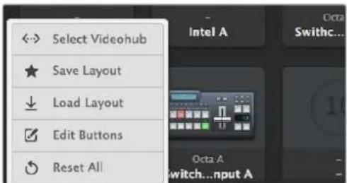
Haxmite Select Videohub u Bb6epnte Hyxhoe yctpoiCTBO Videohub
O6aBHeHne KHOHOK
Ha3aOK HAcTpoek N Bb6epnte Edit Buttons. LKeKHTe KhONkY Add n ykaKNTe
HcTOHn Knn npemHnK CnHana, KOtOpBn HyxHO do6abNTb. OTKpoetc OKHO Set Button,
B KOTOPOM MOXHO 3aDaTb Heo6xOdMble napamETpbl, nopT RS-422 n 3aOHok dN kHOnKn. B
60JIbUnHCTBe cIyaeB ynpabNeHne DeKO crpynnnpoBaHo c onpepeenHbIMn SDI-pa3bEmamn.
PpocmToHnPaBHeHnMaPspTy3aCn
YTo6bI OTo6pa3nTb NtB nepeaun CnHana (Ha npImep, Ha MOHITOp), HaxMnte HyxHyIO KHOKny Ha naHei Destinations. BmecTe C Hei 3aropntc KHOJa COOTBeTCTByUeero ICTOUYHka Ha naHei Sources dIy Bn3yaJIbHO T KOHTpON HAnpabJeHna MapPpyTu3aUN.
I3meHeHne HappaBleHnmaPspTytn3aun
YTo6bI B KaueCTBe NcToUHnka BMeCTo PHeOuHOJ DeKn IcNoIb3oBaT KaMepy, Ha NaHeiN Sources HaxMtTe COOTBETCTByIOU KhoNkO. OHa 3aRopntc, n 1306paXeHne 6yDet BbIOBNTbcr Ha BIndeOMOnHOp. PHeOuHnA DeKa Tenepb OT Hero OKnIOUeHa, n ee KhoNka BoJIbSe He rOpit.
Haxmte Edit Buttons, 06bbl6paBn3o6paxHe 3aKaI nctouHka nn
npHMMKa CnHa
Pa60Ta C KHOKNKAMN
HactpoKa ceTeBbIX npaMeTpoB Ha Blackmagic MultiView 16
Длввoda IP-адраси сеевix napametpoь Ha Blackmagic MultiView 16 npimehyOT BCTpoeHnyo nahe ly npablenya n XX-dicnnei. Ecnna hactpoika bblonHeHa npabInbNo, yctpoiCTBO Blackmagic MultiView 16 byet obnapykeHo Ha dpynx kombokepax n annpaTHbx naHelyx. 3TO pO3BONIT nCNOb3OBaT bIcTaNHOHH KOHTPOb n MeHrtb HapabNeHry MappTytnaun c nomoubIo npiloxeHry Blackmagic Videohub Control.
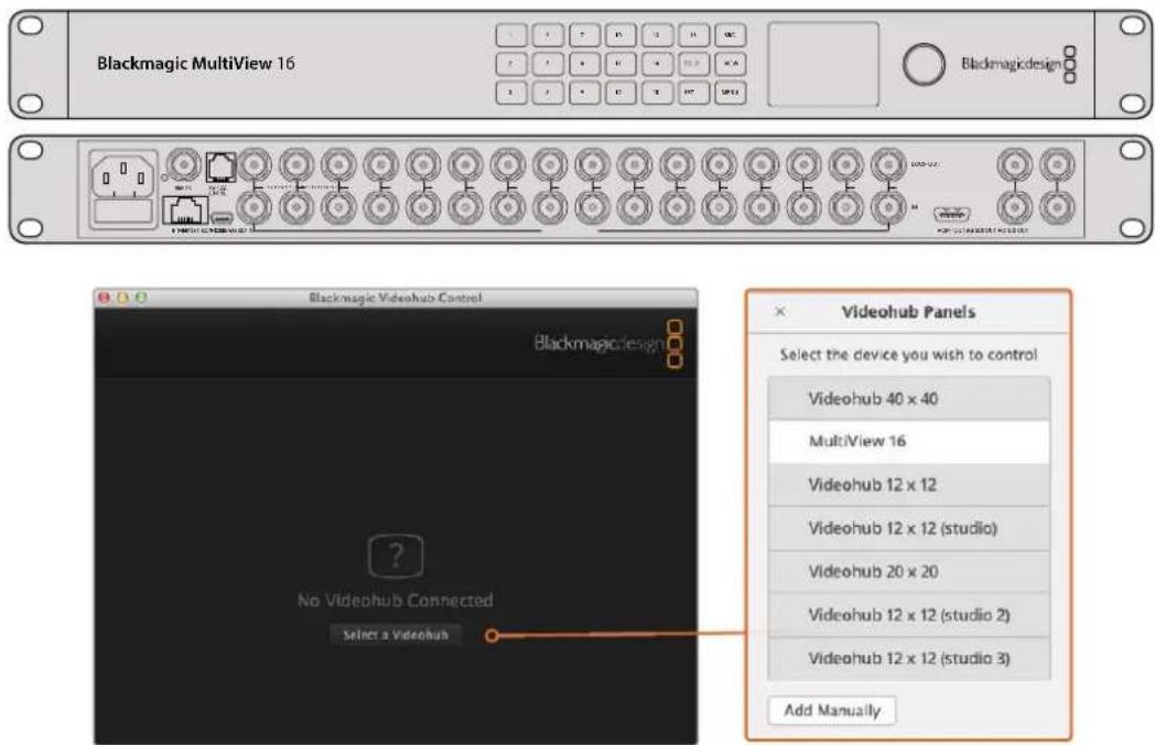
Yto6bnooknouhcbK npnoxehNo Blackmagic Videohub Control, Haxmte KhoNky Select a Videohub n3 npvBeHnro cncka Bb6epTe yctpoCTBO Blackmagic Multiview 16
Iopraok HactpoKn ceteBbix npaMeTpO8
1Haxmnte KhoNky MENU n c nOmoIbIO kpyIIO pyuK Bbl6epnte BknaIky Network.
2 Haxmte KhoNky SET, yTo6b otKpbItb cTpaHnCy ceTeBbix npaMeTpO8.
3 C nomoubkykpylno pyuky Bbl6epnte BknaKy IP Address.
4 Haxmte KhoNky SET, yTo6bI bIeIInIb nepBbI cerMeH aDpeCa. BBoNTb 3HaueHn MoxHo IIO kpyTIOI pyKoI, IIO npOHymepoBaHHbIM NHOKNaMn.
5 Haxmte KhoNky SET, yTo6b noTbePntb 3HaueHne nepBoro cerMehta, 3aTeM NOBtOpnte Te Xe DeIcTBnA dIg CLeDyUoXu Tpex cerMeHTOB apeca. TaKIM Xe cnocobom MoxHO npi Heo6xoImOCTn I3MeHNTb apeca Subnet n Gateway.
6ДЯ Bo3BaPATA K HauJIbHoi CTpaHnIe HaxMIte KhoIky MENUДаBa pa3a.
NoipobHee 6ynpaBHeHn yCpOCTBOM Blackmagic MultiView 16 c nmoosb npinloKeHn Blackmagic Videohub Control cm. pykoBoCTBO no Blackmagic MultiView 16. NocJeHne Bercnn pykoBoCTBa no EKnpyatauHn nporpaMMHoro oBecepeHn MoXHO haHTn BcHTpe NoDepKKn Blackmagic Design Ha cTpaHnce www.blackmagicdesign.com/ru/support.
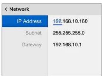
IyctaHOBKcTeBbixnapaMeTPOB
ncnObl3yIne Kpyrnyo pyNkY
nnnpohymepoBaHHBe KHONk
pacnoJokHeHHBe Ha naHeiynpaBneHH
yctpoIcbBa Blackmagic MultiView 16
Videohub Hardware Panel Setup
Pocne oKpbTn yTuNTbI Blackmagic Videohub Hardware Panel Setup Bce haxOJaueeB Cetn naHEny npaBHeN6 bdyT oTo6paKaTc8 co 3NaUkom Ethernet B okHe Videohub Control Panels. EcIn B cnicke HeckoBko naHEny nX HEnb3r onpeDeNtB no NMeHn, Bbl6epnte OndHy nHnx n HaxMnte Identify. Bce KhoKn Ha Bbl6paHHo naHEnn HauHyT MmraTb 6ebim ZBeTom.
Ha BbIeHnHO nAHeN MoXHo N3MeHnT b ee Ha3BaHne HacTpoKu npaBHeN. CeTeBbI napametpb6dyT HeOCTynHbI, TaK KaK INx MoXHo MeHrTb TOnbKO uepe3 nopT USB.
Ecnn onpeendennna naHb ynpablenna Videohub B cetn He o6hApykeha, Bo3MOxHO, OHa H noIyuna IP-anepec no npotokony DHCP. Yto6bl bpyHyIOImeHNTb cTeBbIe napaMeTpbl dIra KOHKpeTHoro yCTpOcTBA, BblONHITe ONcaHHble HNKe DeIcTBnI.
1PoknKouHne naHel ynpaBHeNna Videohub K KombIyTepy KaBeMe USB 2.0.
23anyctte ytnnity Blackmagic Videohub Hardware Panel Setup. Ecn noBntc coo6eHne c npednojKeHm o6HOBt nporpaMMy, cneDyIte HCTpyKuHMa h kpaHe.
3Подсоeинehнячep3 npT USB naneBb 6ydt ABTomaTuceckn Bbl6paHa B OKhe Videohub Control Panels, a pydOm c Hei noRanTc3 hauok USB. TaKoe noKnIOUeHne noZBOJAreT N3MeHnTB kak mMg yctpoNCTBa n HactpoKu ynpabIeHnA, TAK u npaMaTePbI CETn. PocJIe 3aBepseHnI onepaun Ka6bL USB moXHO oTcoeINHITb.
KhONKn BbOpahHn NaHeN ynpaBHeHn 6ydyT 3aropatbcB COOTBeTCTBn C DeIcTBnMn, BblOnHReMbIMn B IIO.
CeteBbIe npaMeTpbl
Дляобмега даннбIMС кOMMyTaTopOM Videohub no IP-сети кадя naHelen ynpaBneHЯ дожн ha MeTb IP-aDpec.
Hactpoika nanei ynpablenia Videohub no INtepecy USB no3Bolnayet Bb6npaTb npotoKoI DHCP iN cratueckn IP-aepc. NepBb Bapnant 60lee Ierkn, taK kApn erO nCnoJIb3OBaHHn HxHhle ceTeBble napamETpb BBODrTcABTOMaTHueckn.
Длу установский сатиеского IP-apeca obpatntecb 3а пошьк К сисмюу adminnuctpapy. Heobxodmo takke BBeCTN daHHble mACKI noCDETN uShIO3 dЯ naHEn ynpaBneHn Videohub. Пп pramom поКLOUeHmK Videohub 6e3 npimHeHn cTeBOrO KOMMyTatopa cNeJyET nCNoIb3OBaTb CTaTNUeCKH IN IP-aDpec.
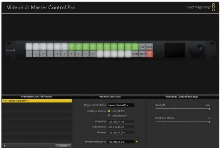
Ytina Blackmagic Videohub Hardware Panel Setup abTomuueckn npoeepet cte Ha hauyne B He nnaeyn ynpabneHria Videohub
CetBbI npaMeTpbI Heo6xOIMBO BBeCTN I B TOM cnUyae, ecnn C nOMOsbIO naHenn ynpabHeHHa Videohub KOHTpOINpyuOT ydaJIeHHoe yctpoiCTBO. TaKOBbIM RAJIeTc cepBep Videohub. OH MOKET npedTabnTb coboi KOMBIOTep Nn BHyTpEHHee IO KOMMyTaTopa (Hanpimep, Smart Videohub 20x20).
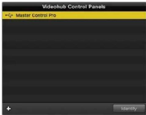
Bce naneHn npabneHHnoKHOeHNbne no cettn Ethernet nnn cepre nopt USB,dynt oTo6paKaTbCn CootBetCTByIOUIM 3aHcKOM B OKHe Vdeohub Control Panels
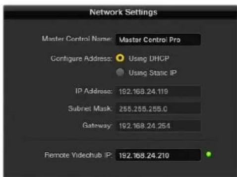
CetBbIe npaMeTpbl Byytnite Blackmagic Videohub Hardware Panel Setup
IynpaBHeHAnnapaTHoNnAeHbIOcNoMoUbBnpyaHbHOKOMMyTaOpa Videohub BBeDte IP-aDpec xocT-KOMNbIePaB nOne Remote Videohub IP.CepBep Videohub Meet taKoi Xe IP-aDpec, KaK N XocT-KOMNbIePep.
D6abHeHne naHn ynpaBHeHna Videohub
Ecn onpeeneHHa naHb ynpabHeVideohub He oTo6paKaetcB OkHe Videohub Control Panels n ee IP-apec n3BeTeH, OHa MoKeT 6bIb doabHe ApyHyIO.
1Haxmnte 3Naoc pIocBa HnKHeu qacto OKHa Videohub Control Panels.
2 BBeDnTe IP-aIpc naneiyn ynpaBneHnaVdoehub n HaxMnte OK.
3 PAneIb ynpabHeHn 6ydt doabHeHa B cnCok noKniOeHHbIX K KomMyTaTopy Videohub yctpoiCTB.
Ecn ytniTa Blackmagic Videohub Hardware Panel Setup He B coToHn HauTn naneB ynpaBHeHn Videohub no yka3aHHomy apecy, ee MoKHO do6aBtB bpyHyIO npn HauNnnoDkIoueHn uepe3 nopT Ethernet nnn USB.
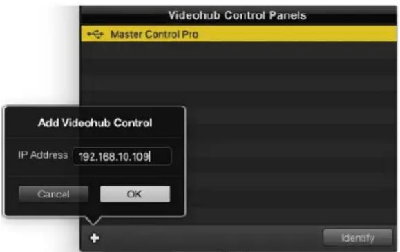
Iobabnt naHnbl ynpaBHeNna Videohub BOKHO Videohub Control Panels moxHo BpyHyIO. Jnra 3ToRo HxKHO OTdeBHO BBectn IP-aDpec.
3arpy3ka n coxpaHHe HacTpoek
HacpoiOnnOHOJIaHEnyIypaBHeNHa Videohub MoXHo IerKo npImeHHTb Ha dpyrnx.
Yto6b coxpaHnTb yctaHOBneHHbIe InaHenn ynpaBHeHnHaCTpoKn, BbIepeNTe File > Save Settings. Tenepb MoXHo 6byet 6bICTo npIMeHNr bix Ha HeckOJIbKnx YcTpoCTBaX IIn IpocTo IMTe pe3epBHyO KOIIIO HAcTpoEk.
Nocne 3aRpy3Kn 3apaHee coXpaHeHHbIX HacTpoeK Ha npTyko naHEnb ynpabNeHnre Heo6xOIMO 06HOBNTb TOnbKO CeTeBbIe npaMeTpbl, BkIOUcay ee Ha3BaHnE.
Hacrtpoika панели Videohub Master Control Pro
Ytnta Videohub Hardware Panel Setup npedHa3nueHa nla HacptpoKn FyHKn naHeeynpablenia Videohub.
POncBetka
ApKocTB nOcBcTK KHOHOK perynpyETc cnaepom Backlight.
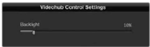
PeynpobKa npKocn noCBeTKBcex KHOIOK H naHEn ynpabneHn
Co3dahne npbIKOB KHOIOK
HaHnA ytniNa Tno3B0JrE TnpCBAuBaTb 21 KHOJIke RaIbIKn TaKOrO cAto NcIOJIb3yEmoO O6OpUdOBaHn, KaK Kamepb, BnDEOMaHHTofoHbI MoHHTopbl. IVx MOXHO TaKKe HAcTpOnTb DnA BbINOJIHeHn MaKpOKOMaHd.
PpeJe Yem npncBaBnBaT JpIbIK KhoNkAM Ha naHEn ynpaBHeHna, cneJyET Chauana onpeJeNTbcra HaimeHOBAHm NOPTOB Ha KOMMyTaTope Videohub.
Iopno6Hee cm. pa3dEe IdoabHne HApIbIKOB Ha KHOIIKn
Tenepb moxno npctynab K co3aHIO npbIKOB dNn KhoNOK naHeN Videohub Master Control Pro.
1OikpoIe yuHnty Videohub Hardware Panel Setup n B okHe Panels Bb6epnte Videohub Master Control Pro.
2UeKHTe OHy n3 21 KHOJOK Ha n3O6paKeHn nAHeJI. BBeJTe TeKCT, KOtOpB i 6bl YaCTNuHO COOTBETCTBOBaI Ha3BaHIO ONDHO n3 nopTOB SDI n ynpaBneHn deKOH Ha KOMMyTaTope.
3HaMMTe OK npeepdnte K cneyiooey KhoNKe.
43anporpammpnoBaHbIe KHOKNMOKHO cpa3y Je npOTecnpoBaTb, YTObI y6eHTbcra, T0 Mapuyn3aunr SDI-cnHana BblonHReTc npabnlho.
IopobHee O npucBoEHn ndeHnФkaTOpOB cm. pa3dEN «O6abNeHne yapbIKOB Ha KHONKn#.
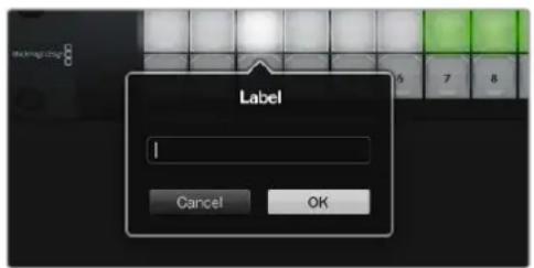
UeKHTKe KhoNky, UTo6bl OtpedakTIpOBaTaee npblk
Hactpoika paheN Videohub Smart Control Pro
Ytnta Videohub Hardware Panel Setup npedHa3nueHa nna HacptpoKn FyHKn naHeeynpaBHeHnVideohub.
YncIIO npneMnKOB cnHaJa
NaHb Videohub Smart Control MoKHO 3aIporpamMPOBaT IJIpeKeNIOeHIN npRbIM cnocobm INB Dba Wara. Pn npRMOM nepeKIOUeHIN KaJdA KHOJa npedctabJIeT cO60 OTdehbl SDI-NCToHIn, N DOCTyNEH TOlbKO OIN H pneMHNK.
PnnepeKIOeHm B Dba ana HEnb Videohub Smart Control Pro MoXet paOToTaB MaKcIMyM c 24 npiemHHKAMn CnHaJa. KHOKN ICTOHNKOB 6dyT rOpetB 6eblm ZBeTOM, pniemHHKOB - 30JOTNCbIM. DaHHbI pexim CnElyET BbIbupaTB TEx CnyaXx, kOrJa Videohub Smart Control Pro nCIOJIb3yeTc dIy BBIOda CNHaJa Ha HeCKoJIbKO npiemHHKOB.
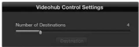
PAnenb Videohub Smart Control Pro Hactpoena dIpa60bI c HeckoIbKIMN pIpeMHNKaMn cnHaIa
Hactpoika pekimama npramoro nepekliouateia
1UCTaHOBIne cIainep Number of Destinations Ha 3NaueHne 1.
2Haxmte KhoNky Destination. B none Router SDI Out A BBeInTe Homep BbIXoHoro npota KomMyTaTopa Videohub, K KOtOpomy NODKIOUHeNo npneMHOe yCTPOINCTBO. Ecn nIra Hero Hyxeh CnHaD Dual Link SDI, noTpe6yETc BBeCTn Homep BbIXoHoro npota B noJrxRouter SDI Out A n B. DnA CnHaJa Quad Link SDI BBeInTe Homepa BO BCEx YeBipex noJrx. PoneRouter Remote HcnoB3yETc B TOM CInuae, KOrDa Ha npneMHNK TaXke nepeDAeTc CnHaI Chepe3 RS-422 dny npablenia deKoi.
3ДляпдьержденяннхмITEOK.BceKhoIGNI,прсдтавлгшпс co60и nctouHKN 3aropTc6bblmCBETOM.
4Yto6bI BbINHHTb HAcTpoKy KHONOK NCTOCHKOB, HAKIMaTe INx NO ODHOBnPoRpaMMHom INHTepFeuece.
5B none RouterSDInA BBeDteHomep BXoHOro nopTa KOMMyTaTopa Videohub, K KOTOpomy 6ydt noKlUeHo nCxOHe yCtpoiCTBO.ДЯ cnHaJa Dual Link SDI notpe6yETcBBeCTn Homep BbIXoHOro nopTa B noJax A n B, a nJa Quad Link SDI - Bo Bcex cheTbipex noJax C A do D. PoneRouter Remote nCnNoB3yEtcB TOM clyae, kOrJa n3 nCTouHnKa taKke nepedaetc cnHaJ qepe3 RS-422 dЯ ynpabLeHnja deKoi.
6ДЯ NOДТВЕРЖDEHЯ HAZMITE OK.
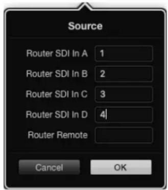
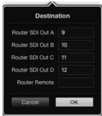
Длгпиема сгнана Quad Link SDI BBeДITE HOMe npTo BO BCex Yetbipex NOJAX
HactpoKa nepeKluueHnB Dba shara
1YctaHOBIne Cnaiep Number of Destinations Ha HnyKHe 3NaueHne.
2YTO6bI BbINOHNITb HAcTPOkny KHOHOK pNEMHKOB, NOCDBceHHbIX 30JIoNTcBIM cBeTom, HaxmaiTe Ix no OndHoi B nporpamMHom INTEpeCe. B noJe Ronter SDl Out A BBeDnTe Homep BbXoHOrO nopTa KOMMyTaTopa Videohub, K KOtOpomy noknOHeNo pNemHoe ycToiCTBO. Dna CnHaJa Dual Link SDI notpebyetc BBeCTn Homep BbXoHOrO npTa B noJAx A n B, a dJa Quad Link SDI - Bo Bcx Yetbipex noJax C A do D. NoJe Ronter Remote nCnObl3yETcB TOM cnUyae, Korda Ha npemHK Takke nepedaetc ciHan uepe3 RS-422 dJa ynpabEnHn deKoJ.
3Длп noTbepKdHnHaXmITE OK. По Мepe yBelenuHEna YnCnA KHOJOK npneMHNKOB yMeHbwaetcra NcIIO DOCTyINbIX KHOJOK NCTOHHKOB.
4TObb BbINHHTb HAcTpOy KHOK NCTouHkoB, HaxmMaTe IN NO OHO B npoPpAMMHOHTEpEuece.
5B none RouterSDInA BBeDteHomep BXoHOro nopTa KOMMyTatopa Videohub, K Kotopomy 6ydt noKnIOUeHO nCxOHDoe yCTpoIcTBO.ДЯ CnIHana Dual Link SDI notpe6yETcBVeCTn HOpE BbIXoHOro nopta B noJx A n B, a nJa Quad Link SDI - Bo BCex yeTbIpyex noJx c A do D. NoneRouter Remote nCnoNb3yETcB TOM cnyae, kOrJa n3 nCTouHnKa taKke nepedaetc cnHaJI uePe3 RS-422 dIy npabLeHnI deKoi.
6ДЯ noDTBepKdEHHaXmITE OK.
YncnoMaKpocOB
Makpocblno3B0JIaOT haxkAteHm OJHOI KHOIKN I3MeHbTb OJHOBpeMeHHo Do 16 HappaBHeHn KOMMyTaUIN.
1C nomoubio cnaepa Number of Macros akTnBpyTe do 10 KhoNOK MaKpocOB. IIO Mepe yBeHueHnYHCnla KHONOK MaKPOCOB yMeHbShaETcR KOJIueCTBO DOCTyHbIX KHOINOK ITOUHNKOB.
2HaxMMTe 3eNeHyKHOky MaKpOca, YTO6bI OTKpbITb OKHO Macro. BBeDnTe COOTBETCTBYUuJe DaHHbE B NOJx NCTOCHNKOB INPnEMHNKOB (MAKCMMyM 16 nap).
3После завершени селкнITE OK,чтобсохсаньннннннннннннннннннннннннннннннннннннннннннннннннннн
ЗakрытбOKHO.

C NOMOUBO ODHOROMAKPOCMOXHO 3MeHbDo16 HnPaBHeHm MapuTynaa
Khonka TAKE
EcnnakTNBPOBaHa OnuEna Enable Take Button, KhoNka B HxHem npabOM yrny nHTepFeca 3aRopntcKpachbIM cBeTOM. Oha nCnoNb3yETcI dIra doNoHInTeNbHO rOndTBepXdEHn I3MeHeHn. HaxMITE KpaChHyIO KhoNky, YTObI NOITBepDNTb HOBOe HapPABHeHne MapWpyTu3aUH. DaHHa IIpoueDpya MoXe InpMeHrbcI npi nepeKIOUeHm IIpMaBIM CnOCobOM N B Dba Wara, a TaKke pni nCnoNb3OBaHm MaKpocOB.
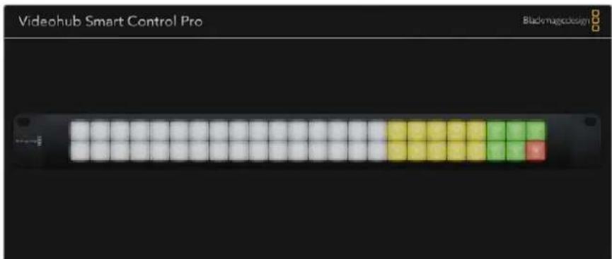
KHONKA TAKETROPIT KPAHBMUBETOM HINKHEM npaBOM yTny
POncBETka
C nmoouo cnaepa Backlight perynpyot npckctnoocbkn KhoNOK. Yto6bl BkHouHTbe eon 6benx KhoNOK nctOunKOB, AKTNBPyTe onuio Backlight Destinations Only.
HactpoynKa KOHTaKToB GPI
GPI and Tally Interface NMeet BOCemB BXoOB nIa3MeHHeMa MapuTua. HanpImep,ecn KOntakr GPI 1zambkaetc, cunHan co BXoJa 12 yctpoiCTBa Videohub 6ydt noctynatb Ha Bbxod 1. 3To O3Haayet, yTO npN BKIOUeHHn ynpabNeHHa JKOCTIKOM Ha 6Noke CCU noLyaeMoe Ha BXOJe 12 I3o6paKeHHe BBODHTcRa MoHITOp.
HarpablenHe Mapspuytnaun Moxno Ierko Hacptb Byytntte Videohub Hardware Panel Setup c noMoou npBedeHn DnaqpaMMbl:doCTaTOUHO IpocTo BBecTu Homepa B nonax Input n Output.
B OKHe Videohub Control Settings npINBOIDITcRA DBA cnOCoBa npocmoTa CnHana c KOMMyTatopa Videohub.
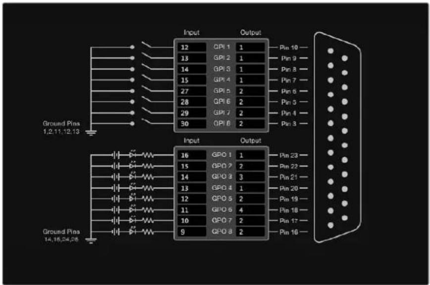
BbIepnteHaIaIpaMMeHyXHbIeBXOdbIbIXOdbIdHaCTpOKnBbIOda MOHTOpuHraNcoCToHn
Latch Video (Фиксаньдю)
Ecnny Hxno octabntb Tekyuee Bndeo, nkenhtte onuio Latch Video. 3to o3hauaet, yto nocne nepeeklouhenia B 6loke CCU cnhaunna k a3aHHoro nctouHka 6ydt BbBOHTbcra Ha MOHTOP do tex npop, noka He Bb6epyT dpyro.
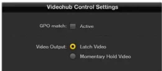
Bb6pntc Latch Video,ecn HxHno npdoanKntb npocmoTdo cneDyoofopeeknOeHn. KorgaKe Tpc6yTcra,TOb6b npn BcBcBooxDeHN npecknOuatoTn npoCxoOn BO3Bpat KnpdeBdyUeMy NCTOHNky, ueKNHe Momentary Hold Video.
Momentary Hold Video (KpaTKOBpeMeHHbI npocMoTp)
Korda Bb6pana DaHHa Onn, npu BbcB60xdeHn nepeKIOUaTeI nn JxOJCTNk BblonHReTc nepexoD obaTHo Ha npedbyuIN nCTouHKn. HanpImep, Ha MOHTOp BbOHTcB BIneo co BxOda 13 npu HaxKaHn uYepXUBaHn nepeKIOUaTeI. Ecn erO OTNyCTNTb, npoundert Bo3Bpat K cnHany co BxOda 12.
Hac troka Tally-ндикции
Tally-nHnDnKaTOp o6bIuHO npedctabJrEe Tco60I naMNoUy Ha nepeDHe nAHeN KaMepbl, KOtOpaR ropit npi nepeDaue CunHana B 3Φnp. TaKoe BN3yaIbHoe 6o3HaueHne coCTOaHn MOKeT IcNoB3OBaTcR HA dpyrom 6opdyoBaHH.
YcTpoIcTBO GPI and Tally Interface NMeet BOCEmb HacTpaNBAembIX BbIXoDB GPO, KOTOpblie nepeaIOT cHnHaII INdkaun Ha KaMepy IIN, pIn onpeJeEHHom HapBaJIeHN MapuTy3aUNn, Ha DpyryIO texhky. B npBedeHHOM npImepe GPO 1akTNBupyETcR B Tom Cnyae, KOrda BnDeo co BxoJa 16 Ha KomMyTaTope Videohub BbIOJNTcRA Ha BixOJ.
Hapablenne Mapspuytnaun Moxno Ierko Hacptonb Bytnte Videohub Hardware Panel Setup c noMoou npBedeHn DnaqpaMMbl: DoCTaTOUHO IpocTo BBecTu Homepa B nIax Input n Output.
GPO match (Приимен综合体 GPO)
YtobckonnpoBaTb hactpoKn GPI B cekuio GPO,aktnBupyte onuio GPO match.C taKo konfngpyauneinHdkatopcoctOHNBAKIOUaetc npnKaJdOMn3MeHeHHnHaPabIeHn MapspTyIn3aun.
Korda daHnha onuia akTbnpoBaHa, cekua GPO Ha dnaIgPamme 6ydt HeodctynHa dna peaKtnpoBaHndoTexnop,noka c GPO match He y6epyt fnaok.

Yto6blckonnpoBaTbHacptpoKnGPIBceKuio GPO, actinbpnyte onuio GPO match
PocleioBatebHoe coeHHHe Heckobkx yctpoCTB GPI and Tally Interface
GPI and Tally Interface nmeet no Bocem BxodOB u BixOoB, yero doctatooh Dnra CbEMKn 60nbHnCTBa TeenporpamM. Ecn Jne nconlb3yeTc 60nee BOCBMn KaMep, MoKHO NOdkIIOHTb Btopoe n daxe tpeBe yctpoictBO GPI and Tally Interface.
YcTpoIcTBO GPI and Tally Interface nMeet Dba nopTa Ethernet. Odn MoXHo NcNoB3oBaTb dIa noKluueHn K KommyTaOpTy Videohub, a npyroi - KdoonHInTeBHOeDinHnce GPI and Tally Interface.
1PoukIIOUHTe nITaHne K nepBOMy yctpoiCTBy GPI and Tally Interface.
2C nomoucbio ctaHapthoro Ethernet-ka6eRJ45 noKIOUHTe npT IN ha GPI and Tally Interface K Kommyatopy Videohub IIN KOMNIOTEpHOc cTeN.
3Подклочпт петане кВТОРМу yсгпСТВу GPl and Tally Interface.
4C nomoubIO cTaNapThoro Ethernet-ka6eRA RJ45 noKlouHte pa3bEm OUT nepBoro yctpoIcTBa GPI and Tally Interface K nopTy IN Btporo.
Ecn moKHO oecneHTb Hx nTahHem, donyckaetc daobabHe ne yctpoiCTB GPI and Tally Interface B IIObOM Heo6xOdumom KOINueCTBE.
Korda npimehareTc Heckolbko edHnGPI and Tally Interface, HOrDa trpydno onpeDenb, KaKaia n3 Hx 3aJeCTBOBaHa B daHHbMMeHT. IeIKNITE KOHKpETHOe yctpoiCtBO GPI and Tally Interface B OKHe Videohub Control Panels n HaxMnte KhONky Identify. B aTOM cIyue Ha hem pIaOM C noptom IN 3aropitc CBetOIOJ.
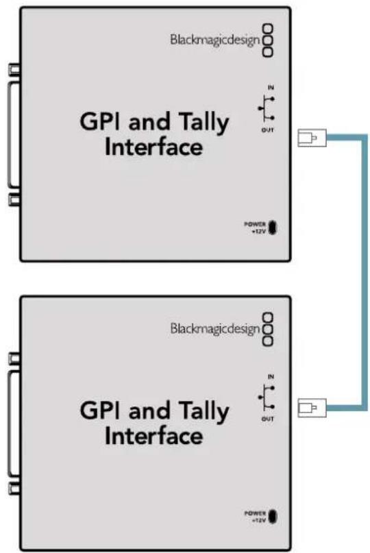
IocneBatoBHeoe coeHHeHne HeckoBkx yctpoCTB GPI and Tally Interface c noMoUbIO Ethernet-ka6en. KaKdbn n3 HIN DOJXEN ObecneHbTaBCr NITaHnEM.
Добavenhoe yctpoctba GPI and Tally Interface no cetn
Hnorga Tpe6yetc Hactpontb yctpoctBO GPI and Tally Interface, KOtOpoe HaxoDntc B ydaenHOM MecTe N DOCTynHO ToIbKO No cEtN. Ero moXHo Do6abNTB CnucOK BpyHyIO. IIna 3TOrO HyxHO BBECTn COOTBeTCTByoum IP-aDPEC ByTNlne Videohub Hardware Panel Setup.
EcnIP-aPecdoabAemoro yctpoiCTBa GPI and Tally Interface Heu3BecTeH, noKIOHTe ero K KOMbItepy cepes USB-nopT, oKpOte ytnity Videohub Hardware Panel Setup n 3aunite IP-aPec B okne Network Settings.
Korda yctpoiCBO paCnoIooKeHO B ydaJIeHHom MecTe N DOCTyNA K Hemy Het, eRo MOxHO HaHTN B cETn C NOMOsbIO 6pay3epa Bonjour. DAnHoe npInIOXeHne No3BONJeT YbUdTeB BCIO HaxOJaIyOcB B cETn TexHky I ee IP-aDpeca, B TOM YncIe dIg GPI and Tally Interface.
1Haxmnte 3haok nioca B HnKHeu actn OKHa Videohub Control Panels.
2BBeDnTE IP-adpec yctpOcTBA GPI and Tally Interface n HaxMnTe OK.
3Btopoe yctpoiCTBO GPI and Tally Interface 6ydt doabneHO B cncok nodknoeHHo K kOMmyTatopy Videohub texnkn.

Haxmte 3aocnna BBe nte IP-epc doabneMoro yctpoicBa GPI and Tally Interface. Haxmte KhoNky Identify, tO6bHa BBpaHoe eHNue GPI and Tally Interface BKIOUHT CBToND.
UctaHOBka yctpoiCTBa GPI and Tally Interface
Hactpoyn yctpoinCTBa GPI and Tally Interface 3aiaot c nomoub ytnihty Videohub Hardware Panel Setup. Ipeed hauanom ero ncoNb3OBaHn moKet noHaobc yctahOBka nocneHeBepcnn PO.
1ПоdkлочипитанькустpoиCTBy GPI and Tally Interface.
2Подклочite GPI and Tally Interface K komlbTepy kabeIem USB (A/B).
3Otkpoite ytnity. OHa onpeenit, 6bIIO JyycptpoictBO GPI and Tally Interface Hactpoeho dIpaobtbcOMmytaTopom Videohub pahee. Ecnna da, nImeHnne He notpe6yioTcB. B npotubHom cnyae noBntcra coo6ueHne o Tom, YTO GPI and Tally Interface Imeet KOHfnpaunIO dIpaobtbc BNdeomnkwepom ATEM n ee heo6xOIMO ckopkeKtpoBaTb dI pymHeHnca KOMmytaTopom Videohub. HaxMITE Yes, n Upe3 Heckonbo cekynd ycptpoiCTBO GPI and Tally Interface 6ydt nepehactpoeho doJXhIM o6pa30m.
HactpoJa yctpoiCTBa GPI and Tally Interface
KordaHa KOMmyarope Videohub Het npTa Ethernet nnn doctyn K Hemy Bo3MOxeh TOnbko NocETN, BblONHnTe cIeDyUoJe DeiCTBnJ.
1ПодклочиустpoисвО GPI and Tally Interface K Komпьтepу kabelenm USB (A/B).
2CoeHnnte Ka6enem Ethernet nopt IN ha yctpoicBe GPI and Tally Interface COOTBcTByOuI npa3bem HA BndeomKwpepe.
3OTkpoIe yTnIITy Videohub Hardware Panel Setup.
4B OkHe Videohub Control Panels donxho noaBtbcyaYcTpoiCTBO GPI and Tally Interface co 3Nauchom USB.Даиte emy yHnkaIbHoe IMR, YTObI erO sbIIO nerKo haHTN.ДЯ AToro yctahOBITE Kyccop B NOIe Name n BBeDInTE IMR.
5ДЯн�рои IP-адра CBbepte onuO Using DHCP nU Using Static IP.чroБы ONpeDEJIITbcra, kakay n3 HnX lyuWe IOxOaNT, obpaTInTeCb 3a NOMOsbK CnCTeMHOMy adMNHnCTpaTopy.
6B none Remote Videohub IP BBeIne IP-apec KommyaTopa Videohub, K kotoPOMy BbIOnHReTc noKnIOHeHne. Korda OHO yCTaHOBnTcR, HaxOJaAraC praOM c noIeM kpacHaJ lamnoUka cTaHET 3eneHoi, a Ha ycToPiCTBe GPI and Tally interface 3arOpntc caTeoNIOd.
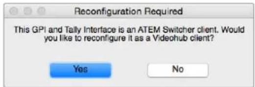
Ja pa6oTb c KOMMyTaTopom Videohub HAcTpOKn yCtpoiCTBa GPI and Tally Interface Tpe6yeTcN3MeHnTb
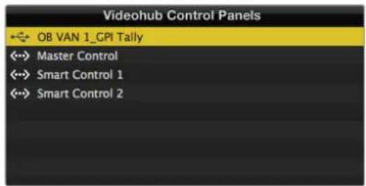
YcptpoctBO GPI and Tally Interface nodknoeNo uepe3 nopT USB
Korda IP-aDPEC KOMMyTaTopa Videohub HEN3BcTeH, BbINOJIHnTE CneIyIOJIe DeICTBnI.
1ПодклочиTe kOMMyTaTOp Videohub K kOmMbIotepy chepe3 nopT USB.
2OtkpoTe IO Videohub uIeKnTe Videohub Server Preferences.
3 3aannnre IP-adpec, noka3aHHbB none Remote Videohub IP.
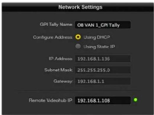
BbDnHaBaHn yctpoiCTBa GPI and Tally interfacn Hnacptpoika IP-epcca KOMMyTaTopa Videohub, K KOTOPoMy BblonHReTcnoKnIoueHne
Developer Information
Blackmagic Videohub Ethernet Protocol v2.3
Summary
The Blackmagic Videohub Ethernet Protocol is a text based protocol that is accessed by connecting to TCP port 9990 on a Videohub Server. Integrated Videohub Servers and Videohub Server computers are supported by the protocol.
The Videohub Server sends information in blocks which each have an identifying header in all-caps, followed by a full-colon. A block spans multiple lines and is terminated by a blank line. Each line in the protocol is terminated by a newline character.
Upon connection, the Videohub Server sends a complete dump of the state of the device. After the initial status dump, status updates are sent every time the Videohub status changes.
To be resilient to future protocol changes, clients should ignore blocks they do not recognize, up to the trailing blank line. Within existing blocks, clients should ignore lines they do not recognize.
Version 2.3 of the Blackmagic Videohub Ethernet Protocol was released with Videohub 4.9.1 software.
Protocol Preamble
The first block sent by the Videohub Server is always the protocol preamble:
PROTOCOL PREAMBLE:
Version: 2.3
The version field indicates the protocol version. When the protocol is changed in a compatible way, the minor version number will be updated. If incompatible changes are made, the major version number will be updated.
Device Information
The next block contains general information about the connected Videohub device. If a device is connected, the Videohub Server will report the attributes of the Videohub:
VIDEOHUB DEVICE:
Device present: true
Model name: Blackmagic Smart Videohub
Video inputs: 16
Video processing units: 0
Video outputs: 16
Video monitoring outputs: 0
Serial ports: 0
This example is for the Smart Videohub which is a 16x16 router.
If the Videohub Server has no device connected, the block will simply be:
VIDEOHUB DEVICE:
Device present: false
←
If a device is present, but has an incompatible firmware, the status reported will be:
VIDEOHUB DEVICE:
Device present: needs update
In the last two situations, no further information will be sent, unless the situation is rectified.
If the Videohub Server detects a new Videohub attached, it will resend all blocks except the protocol preamble to indicate the device has changed, and allow the client to update its cache of server state.
Initial Status Dump
The next four blocks enumerate the labels assigned to the input, output, monitoring and serial ports.
Videohubs that do not have monitoring or serial ports do not send the corresponding blocks.
INPUT LABELS:
0VTR1
1 VTR 2
解法1
OUTPUT LABELS:
0 Output feed 1
1 Output feed 2
中中
MONITORING OUTPUT LABELS:
0 Monitor feed 1
1 Monitor feed 2
←
SERIAL PORT LABELS:
0 Deck 1
1 Deck 2
NOTE Ports are always numbered starting at zero in the protocol which matches port one on the chassis.
The next three blocks describe the routing of the output, monitoring and serial ports.
VIDEO OUTPUT ROUTING:
0 5
1 3
...
VIDEO MONITORING OUTPUT ROUTING:
0 7
1 8
...
SERIAL PORT ROUTING:
0 12
1 11
...
Videohubs with processing units (only the Workgroup Videohub) send an extra routing block:
PROCESSING UNIT ROUTING:
0 5
1 3
…
Video hubs with frame buffers (only the Workgroup Videohub) send two extra blocks:
FRAME LABELS:
0 Frame one
1 Frame two
...
<1>
FRAME BUFFER ROUTING:
0 7
1 8
...
The next three blocks describe the locking status of the output, monitoring and serial ports. Each port has a lock status of "O" for ports that are owned by the current client (i.e., locked from the same IP address), "L" for ports that are locked from a different client, or "U" for unlocked. Note that Video hubs that do not have monitoring ports or serial ports do not send the corresponding blocks.
Videohubs with processing units (only the Workgroup Videohub) send an extra lock block:
PROCESSING UNIT LOCKS:
0 U
1 U
...
Videohubs with frame buffers (only the Workgroup Videohub) send an extra lock block:
FRAME BUFFER LOCKS:
0 U
1 U
...
Videohubs with serial ports next send a block which describes the direction of each serial port. Each port has a direction of either "control" for the "In (Workstation)" setting, "slave" for "Out (Deck)", or "auto" for "Automatic".
SERIAL PORT DIRECTIONS:
0 control
1 slave
2 auto
...
Videohubs with pluggable cards (only Universal Videohubs) send three more blocks that describe the hardware status of the ports. Missing video or serial ports have a status of "None"; input and output video ports will be "BNC" or "Optical" if they are present; serial ports will be "RS422" if they are present.
VIDEO INPUT STATUS:
0 BNC
1 BNC
VIDEO OUTPUT STATUS:
0 BNC
1 BNC
...
SERIAL PORT STATUS:
0 RS422
1 RS422
Status Updates
When any route, label, or lock is changed on the Videohub Server by any client, the Videohub Server resends the applicable status block, containing only the items that have changed. For example, if serial port 6 has been unlocked, the following block will be sent:
SERIAL PORT LOCKS: 5 U
If multiple items are changed, multiple items may be present in the update: OUTPUT LABELS:
7 New output 8 label
10 New output 11 label
If a card is plugged into or removed from the Universal Videohub, it will send hardware status blocks for the video inputs, video outputs, and serial ports on that card.
Requesting Changes
To update a label, lock or route, the client should send a block of the same form the Videohub Server sends when its status changes. For example, to change the route of output port 8 to input port 3, the client should send the following block:
VIDEO OUTPUT ROUTING:
7 2
The block must be terminated by a blank line. On receipt of a blank line, the Videohub Server will either acknowledge the request by responding:
ACK
or indicate that the request was not understood by responding:
NAK
After a positive response, the client should expect to see a status update from the Videohub Server showing the status change. This is likely to be the same as the command that was sent, but if the request could not be performed, or other changes were made simultaneously by other clients, there may be more updates in the block, or more blocks. Simultaneous updates could cancel each other out, leading to a response that is different to that expected.
In the absence of simultaneous updates, the dialog expected for a simple label change is as follows:
OUTPUT LABELS:
6 new output label seven
ACK
OUTPUT LABELS:
6 new output label seven
The asynchronous nature of the responses means that a client should never rely on the desired update actually occurring and must simply watch for status updates from the Videohub Server and use only these to update its local representation of the server state.
To lock a port, send an update to the port with the character "O" indicating that you wish to lock the port for example:
SERIAL PORT LOCKS:
7 O
←
ACK
←
SERIAL PORT LOCKS:
7 O
To forcibly unlock a port that has been locked by another client, send an update to the port with the character "F" instead of using the usual unlock character "U". For example, to override a lock on port 7:
SERIAL PORT LOCKS:
7 F
ACK
SERIAL PORT LOCKS:
7 U
Hardware status blocks can only be sent by the Videohub Server. If a client sends hardware status blocks, they will be ignored.
Requesting a Status Dump
The client may request that the Videohub Server resend the complete state of any status block by sending the header of the block, followed by a blank line. In the following example, the client requests the Videohub Server resend the output labels:
OUTPUT LABELS:
ACK
OUTPUT LABELS:
0 output label 1
1 output label 2
2 output label 3
...
Checking the Connection
While the connection to the Videohub Server is established, a client may send a special no-operation command to check that the Videohub Server is still responding:
PING:
←
If the Videohub Server is responding, it will respond with an ACK message as for any other recognized command.
Videohub RS-422 Protocol
General
The RS-422 protocol can be used to control many Videohub models as RS-422 slave devices, for router crosspoint switching. This feature is available on any Videohub model with an "RS-422 Control" port.
Depending on your model of Videohub, the RS-422 port may be either a DB9 or RJ11 connector. DB9 cables are commonly available in electrical stores. The RJ11 connector is the same used in many landline telephone connections. By modifying an RS-422 to USB adapter cable terminated with an RJ11 connector you can control Videohub using external controllers via USB.
In "Leitch Server" mode, these Videohub models implement the router (server) side of the Leitch Serial Pass-Through Protocol as specified in section 4 of Leitch document SPR-MAN revision D. In "Leitch Client" mode, the Videohub implements the controller (client) side of the Leitch terminal protocol.
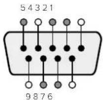
| Pin Function | |
| 1 Ground | |
| 2 Tx- (Data sent by router) | |
| 3 Rx+ (Data received by router) | |
| 4 Ground | |
| 5 NC (No connect) | |
| 6 Ground | |
| 7 Tx+ (Data sent by router) | |
| 8 Rx- (Data received by router) | |
| 9 Ground |
Videohub RS-422 Router Control DB9 pin connections.
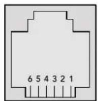
| Pin No. Function | |
| Pin 1 | TX + |
| Pin 2 | TX - |
| Pin 3 | GND |
| Pin 4 | GND |
| Pin 5 | RX - |
| Pin 6 | RX + |
Videohub RS-422 Router Control RJ11 pinout diagram.
This document describes the commands and parameters in the protocol that are relevant and supported by Videohub. Other commands and parameters specified in the Leitch protocol are accepted but ignored.
The RS-422 serial port is configured as 9600 N81.
The protocol is line-oriented, with a maximum length of 250 characters per command. Each command from the client should be terminated with a carriage-return (r). Each response from the server will be terminated with a carriage-return and line-feed (r\n).
Sources, destinations and levels are always specified in base-16, numbered from zero. Levels are always between 0 and 15 ("F"). Videohubs only have one valid level - level zero.
On connecting to the serial port, the client should send a carriage-return. The Videohub Server will respond with a > character prompt, which is not followed by a carriage-return or line-feed. Receiving the prompt indicates that a connection has been established. The same prompt will be issued after each command received by the Videohub Server.
In the following documentation, commands in orange and values in blue must be typed literally, including any spaces. In the following example of an immediate command using destination port 7 and source port 3, @ X:0/destination, source would be entered as: @ X:0/6,2
Notifications
Once connected, if status reporting is enabled, the client will receive a notification message when a route changes on the Videohub Server. The notifications take one of two forms:
S:0destination,source Routing change
This message indicates that the specified source port is now routed to the specified destination.
V:0destination,source Preset routing notification
This message indicates that the current preset includes a route from the specified source to the specified destination.
Global Commands
All pass-through commands are preceded by an 空 symbol and a space.
The following client commands are supported:
品 disable status reporting
Status reporting is disabled by default.
? enable status reporting
Status reporting is enabled.
@ Z: reset routing table
Routing is reset so that the first source is routed to all destinations.
Immediate Commands
X:0/destination,source change route
@ X:0/destination,source/destination-2,source-2... change multiple routes
The specified source ports are routed to the specified destinations.
Any routing changes will trigger S: notifications
@ X?0destination request individual route status
The source routed to a the specified destination will be returned as an S: notification.
S?0 request all ports route status
Each source & destination port pair will be returned as S: notifications
Salvo Commands
P:0/destination,source queue route change
@ P:0/destination,source/destination-2,source-2... queue multiple route changes
The specified routing changes are added to the current salvo for later execution.
@ P?0destination request individual port status in salvo
If a routing change for the specified destination port is queued, the route will be returned as
a V: notification.
@ V?0 request all ports status in salvo
Each queued routing change in the salvo is reported as a V: notification.
B:C clear salvo
B:R clear salvo
Any queued changes are discarded and the salvo is reset.
B:E execute salvo
Any queued changes are executed and each routing change will be returned as an S:
notification.
Saving and Loading Labels with Telnet in Mac OS
Normally you would use Blackmagic Videohub Setup to save and load labels between different Videohub routers and to backup your videohub settings. However, if for any reason you wish to use the Terminal, the instructions below let you save and load router label configurations via the Terminal.

Saving Labels
1 Open the Terminal application which is located within the Applications > Utilities folder.
2Type in "telnet" and a space followed by the IP of your Videohub, then another space and "9990", which is the default port number. For example type: telnet 192.168.25.253 9990. The Protocol Preamble screen will appear.
3 Copy the INPUT LABELS: text including the heading and paste into a word processor or simple text editor. Name this file "input labels" and save to your favorite location.
4Copy the OUTPUT LABELS: text including the heading and paste into a word processor or simple text editor. Name this file "output labels" and save to your favorite location.
5Close the telnet session by exiting the terminal window.
Loading Labels
1 Open the Terminal application with is located within the Applications > Utilities folder.
2Type in "telnet" and a space followed by the IP of your Videohub, then another space and "9990", which is the default port number. For example type: telnet 192.168.25.253 9990. The Protocol Preamble screen will appear.
3 Open the "input labels" text file in your text editing program and copy the INPUT LABELS: text.
4 Paste this into the telnet session and press "return" twice. Telnet will respond with "ACK" and Videohub will update the input labels.
5Open the "output labels" text file in your text editing program and copy the OUTPUT LABELS: text.
6 Paste this into the telnet session and press "return" twice. Telnet will respond with "ACK" and Videohub will update the output labels.
7Close the telnet session by exiting the terminal window.
Saving and Loading Labels with Telnet in Windows
While you can save and load labels within Blackmagic Videohub Setup, you may also download and use PuTTY which is a free telnet client.
Setting up PuTTY
1 Start the application and in the "Host Name" field, type the IP of your Videohub and in the "Port" field type "9990", which is the default port number.
2From the Connection type options select the "Telnet" radio button.
3Select the "Terminal" tab and tick the "Implicit CR in every LF" checkbox.
4 Click the "Session" tab and save your session parameters by entering a name in the "Saved Sessions" field and clicking the "Save" button.
Saving Labels
1 Double click the PuTTY icon to start the application. Select your saved session from the list and click the "Load" button followed by the "Open" button. The Protocol Preamble screen will appear.
2 Copy the INPUT LABELS: text including the heading and paste into a word processor or simple text editor. Name this file "input labels" and save to your favorite location.
3Copy the OUTPUT LABELS: text including the heading and paste into a word processor or simple text editor. Name this file "output labels" and save to your favorite location.
4Exit the telnet session by closing the PuTTY window.
Loading Labels
1 Double click the PuTTY icon to start the application. Select your saved session from the list and click the "Load" button followed by the "Open" button. The Protocol Preamble screen will appear.
2 Open the "input labels" text file in your text editing program and copy the INPUT LABELS: text.
3 Right click in the PuTTY session to paste the copied section and press "Enter" twice. PuTTY will respond with "ACK" and Videohub will update the input labels.
4 Open the "output labels" text file in your text editing program and copy the OUTPUT LABELS: text.
5 Right click in the PuTTY session to paste the copied section and press "Enter" twice. PuTTY will respond with "ACK" and Videohub will update the output labels.
Exit the telnet session by closing the PuTTY window.
PROTOCOL PREMATURE:
Version:2.4
VIDEOHUB DEVICE:
Device present: true
Model name:Blackmagic Smart Vidcohub
Unique ID:7c2e0d0106df
Video inputs:16
Video processing units:0
Video outputs:16
Video monitoring outputs:0
Serial ports:0
INPUT LABELS:
0 Camera 1
1 Mini Converter 1
2 Hyperdeck 1
3 VTR 1
4 Teranex 1
5 PC Workstation
6 ATEM PSM
7 Camera 2
8 Mini Converter 2
9 Mac Workstation
10 Hyperdeck 2
11 VTR 2
12 Teranex 3
13 Hyperdeck 3
14 Hyperdeck 3
15 Input 16
OUTPUT LABELS:
0 Main Monitor 1
1 Main Monitor 2
2 Audio Monitor 1
3 Audio Monitor 2
4 ATEM Input 1
5 ATEM Input 2
6 ATEM Input 3
7 Hyperdeck 4
8 Hyperdeck 5
9 Hyperdeck 3
10 VTR 3
11 VTR 4
12 Teranex 4
13 Ultrascope 1
14 Ultrascope 2
15 Ultrascope 3
VIDEO OUTPUT LOCKS:
0 U
1 U
2 U
3 U
4 U
5 U
6 U
7 U
8 U
9 U
10 U
11 U
12 U
13 U
14 U
15 U
COOTBETCTBNE Tpe6oBaHnIaM ISED (KaHaDa)
Данhoe obopydobahne COOTBeTCTByeT KaHaDCKIM CTaHapTaM ДЯ UФpoBbIX yctpoiCTB KlaCCA A.
JIO6a MoIINKauNn IIN NcNoB3OBAHne I3dEInn He No Ha3HaueHnIO MOryt NobIeB 3a C06oI aHNIpOBaHne 3aBbIeHHN O COOTBETCTBUN 3TmN CTaHdApTAM.
IopKIOUeHne K HDMI-HHTepFeiCy DoJXHO BbINONHtBcR C NOMOUIIO KaueCTBeHHoro 3kpaHnpoBaHHoro Ka6en.
DaHHe OOBpyOBOAHn IpoteCTnpoBaHO No Tpe6oBAHm, PpeBraBmK yCToPcTbAM npi paBoTe B HexNlby NOMEeHNx. Pn INCNoB3oBAHm B 6bITOBbx YCIOBnx OHO MOKeT CTaHOBtbcr NTOCHNKOM NOMex dIpaDIOcHHaIa.
ПразвILA 6e3ОпасноCTN
Bo n36eXaHne ydaap a 3eKtpnueckm Tokom po3etka IJNIOkIIOUeHn yctpoCTBa K cETN OJIXHa IMeTb 3a3eMnIouu KoHTaKT. Pn Heo6xOIMOCtn o6paTNTecb 3a NOMOuBIO K KBaIIINΦuIUPOBaHHOMy 3eKtpnky.
YTo6bIMNIMM3IPOBaTb OAnCHOCTb NopaxeHnE 3eKtpueckm TOKOM, n3dene Heo6xOIMO 3aunuATb OT nonadHnE 6pb3r N KaneB BObl.
DonyckaetceraKcnnyataaB yCNOBnX TpOnuueckoro KImMaTc TemnepaTypoN OKpykaioe cpebl do 40^
-3G-SDI:PL-4F20-311C

DonyckaetcAeknnyatauB Mectax He Bbwe 2000 MetpoB Hd ypOBHem Mopra.
YBeDomJIeHne dIg XHTeIe Wtata KaIIΦOpHnIa
Pn pa6oTe c 3Tm O6opdyoBaHem CyueCTBye T B03MOXHOCTb KOHTa C coepkaUIMNcB IIaTMacCe MkPOnpImeCMA MNHO6POMICTO r 6nfeHNla, KOTOpB IN B Wtate KaINΦOpHnI np3HaH KaHcePOReHOM I yBeInuHBAET PnCK BPOXDeHHbIX DeΦEKTOB IN NopoKOB peNoDyKTHBHO nCTEmbl.
Iopno6Hee cm. INHOpMaunio Ha caTe www.P65Warningsca.gov.
PpeDynpexdeneIe IeyHueckoro nepcoHaJa
Ipepeo6cnykBaHemOTKIOUHTe nHTaHHe Ha 60nX CINOBbIX pa3beMax.
OcToPoxHo: nIaBKn npedoxpaHnte bDByxNIOChb/N HeHTpAn
BIOK NITAHIN B ATOM yCTPOINCTBE IMeET npedoxpaHNTIEL B IINHeHOM HnHTpAIBHOM npoBOaX n IOxOINT DnI NOkNIOUChEN K CnCTEmE 3HepronntAHIN TnA IT B HopBernn.
Гаразня
OrpaHnueHHa rapaHTna
KomnaHnBaCKmAgic Design rapaHTnpyET oCytCTBne B KOMMyTaTope Videohub deFeKToB MaTePnAla n npOn3BOJCTBeHHoro 6paka B TeueHne 36 MecuEe C daTb npOaXn. Ha pa3bEmbl, KaBenn, OXJaXdaUoIe BENTINaTOpbl, ONTOBOLOKOHNbIe MOdynn, npedoxpaHntEn, KJIaBnAtypbl n akKymyTAToPbIe 6batapeN Takayra pAHn DaehCTByet B TeueHne 12 MecaeB C daTb npOaXn. Dnla moJeNei Videohub Master Control n Videohub Smart Control rapaHTn OTCytCTBn DeFeKToB MaTePnAla n npOn3BOJCTBeHHoro 6paka DeHCTByet B TeueHne 12 MecuEe C daTb npOaXn. Ecnn BO BPemr rapaHTnHOrO cpoKa 6byT BbIaBHeIb DeFeKtbl. Blackmagic Design no CBOemy yCMOTpeHIO BbIOnHIT peMOHT HeNCnPabHoro N3deLNa 6e3 OIIaTb CTouMoCTn 3aNacteN IN TpyD03atpat INI 3aMeHNT TAKoe I3dJIe HOBBM.
YTO6bI BOCNOB3OBAbCra HactoIe rapaHtnne, NTope6ntel 083aH yBeDMNTb KOMnHIO Blackmagic Design o deFekTe do OKOHuaHra rapaHTnHoro cpoKa n OecneuHTy YcNoBnaDn npEOCTabHeHr Heo6xOIMbIX ycLyr. NTope6ntel HeCet OTBetCTBeHHocTb 3a yNakOBky I DoCTABKy HEnCnpaBHOrO INdEInB B COOTBetCTByUOn CepBnCHbI LcHtp Blackmagic Design c OnnatoN noTobix paXoOB. NTope6ntel 083aH ONnATb BCE paXoDbI NO DOCTABKe I CTpaxOBaHIO, NoONnHbI, HAnorN INhIbe C6OpbIB CB3N C Bo3BpaTOM INdEInB BHE 3aBNCUMOCTN OT pNCHbI BO3Bpata.
Hactoiaa rapaHTna He pacnpoctpaHreTaHa deFeKtbl,OTka3blIOBpeKdHnA,BO3HKuue n3-3a HeHaJIeXaIero nCNoIb3OBAHnA, HnPaBnIbHorO yxoJa nn OBCJyXuBaHnA. KomnHnA Blackmagic Design He o6ra3aH npedocabTb yclny no hactoae rapaHTnn: a) dIn yCTpAHHeHH NoBpeKdEnH, BO3NkUHX B pe3yIbTaTe DeiCTBn no yCTaHOBe, pEmOnTy nIn 06cIyXuBaHnIO 3deJIy IINuAMn, KOToPbe He AByIOTc nepcoHaON Blackmagic Design; 6) dIn yCTpAHHeHH NOBpeKdEnH, BO3NkUHX B pe3yIbTaTe HeHaIeXaIero NcNolb3OBAHnA INIOKnIOUeHH N HeCOBMeCTUMOMy O6OpYDoBaHnIO; B) dIn yCTpAHHeHH NOBpeKdEnH nn DEeKTOB, Bb3BaHbIX nCNOb3OBAHnEM 3anuaTeen mAtepnAnOB dpyrnx npOnzBoDnteJe; r) ecIn n3deJIe6 bIIO MoDnΦuIupoBaHO nn INTEpnpoBaHO c DpyrIM O6OpYDoBaHnEM, KOrDa TaKaA MoDnΦuKaUHA nn INTEpRaAry YBeLnuBaET Bpemn nn NobIbAet CLOxHoCTb O6ClyXuBaHnIA n3DeJIeN. HACTOILAR TAPAHTH N PPEIOCTABJRETCR KOMPAHNE BLACKMAGIC DESIGN BMECTO LIO5bIX DPYrNX PPRAMO BbIPAXEHHbIX IIN N ODPAA3YMEBAEMbIX TAPAHTH. KOMPAHNA BLACKMAGIC DESIGN IN EE DNIEPbI OTKA3bIBAOCTCR OT IIO5bIX N ODPAA3YMEBAEMbIX TAPAHTH. KOMMEPUECKOI UEHOOCTNI ININ INPINOHOCTN DlRA KAKOI-NINBO ONPEDELEHHO UELIN. OTBETCTBEHHOCCTb BLACKMAGIC DESIGN IIOPEMOHTY ININ 3AMEHE HEICNPABHbIX N3DEJIIN RBLETCRAIOHN M INCKLIQUHTeJIbHBm CPEICTBOM BO3MELUEHN, PPEIOCTABJREMBIM NOTPEBNTELIO BC8R3N C KOCBEHHbIM, FAKTNUCHECKMI, CONVTCTBYIOUIMM ININ NOCLEUYIOUMN YbItKAMN, BHE 3ABNCIMOCTN OT TOFO, BblA INN HET KOMPAHNA BLACKMAGIC DESIGN (JIN5O EE INIEP) PPEIBAPNTELHO IN3BEUHEA O BO3MOXHOCTNI TAKNX YbITKOB. BLACKMAGIC DESIGN HE HECET OTBETCTBEHHOCCTN 3A INPTOBOPABHOE NCIOJIb3OBAHnE O6OpYIOBAHnA CO CTPOHbI NTPE6BNTELIA. BLACKMAGIC DESIGN HE HECET OTBETCTBEHHOCCTN 3A YbBITKN, BO3NKAIOUIE BCJEIDCTBVE NCIOJIb3OBAHnI 3TOFO IN3DEJIIN. PICKN, CB8AHHIE CEFO 3KCIIVYATALINEI, BO3JIAGOTCR HA NTPE6BNTELI.
Copyright 2023 Blackmagic Design. Bce npaba aauuienb. Blackmagic Design, DeckLink, HDLink, Workgroup Videohub, Multibridge Pro, Multibridge Extmc, Intensity n "Leading the creative video revolution" apernctppoBaHk kak ToBapHbC 3aKnB CUSA n npynx cTpaHx. HaaBAHn Dpynx KOMnHn HauMeHOBnnpdyKTOB Moryr TnBnTbcToBAPbIMn 3aKaMn COOTETCTByIOux npaboo6naadateen.
Blackmagic
Videohub

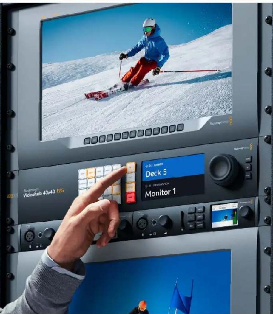
Blackmagic Videohub 12G
Universal Videohub
Smart Videohub CleanSwitch 12x12
Videohub Master Control Pro
Videohub Smart Control Pro
Blackmagic GPI and Tally Interface

Gentile utente
CEO Blackmagic Design
Indices
La linea Blackmagic Videohub 741
GPI and Tally Interface 782
ll software Blackmagic Videohub 783
Blackmagic Videohub Setup 783
Saving and Loading Labels
with Telnet in Mac OS 822
Saving and Loading Labels
with Telnet in Windows 823
GPI and Tally Interface
Momentary Hold Video
Collegare a Cascata diversi GPI and Tally Interface
Configurare GPI and Tally Interface

GPI and Tally Interface collegato tramite USB
The Blackmagic Videohub Ethernet Protocol is a text based protocol that is accessed by connecting to TCP port 9990 on a Videohub Server. Integrated Videohub Servers and Videohub Server computers are supported by the protocol.
The Videohub Server sends information in blocks which each have an identifying header in all-caps, followed by a full-colon. A block spans multiple lines and is terminated by a blank line. Each line in the protocol is terminated by a newline character.
Upon connection, the Videohub Server sends a complete dump of the state of the device. After the initial status dump, status updates are sent every time the Videohub status changes.
To be resilient to future protocol changes, clients should ignore blocks they do not recognize, up to the trailing blank line. Within existing blocks, clients should ignore lines they do not recognize.

Version 2.3 of the Blackmagic Videohub Ethernet Protocol was released with Videohub 4.9.1 software.
Protocol Preamble
The first block sent by the Videohub Server is always the protocol preamble:
PROTOCOL PREAMBLE:
Version: 2.3
The version field indicates the protocol version. When the protocol is changed in a compatible way, the minor version number will be updated. If incompatible changes are made, the major version number will be updated.
Device Information
The next block contains general information about the connected Videohub device. If a device is connected, the Videohub Server will report the attributes of the Videohub:
VIDEOHUB DEVICE:
Device present: true
Model name: Blackmagic Smart Videohub
Video inputs: 16
Video processing units: 0
Video outputs: 16
Video monitoring outputs: 0
Serial ports: 0
This example is for the Smart Videohub which is a 16x16 router.
If the Videohub Server has no device connected, the block will simply be:
VIDEOHUB DEVICE:
Device present: false
If a device is present, but has an incompatible firmware, the status reported will be:
VIDEOHUB DEVICE:
Device present: needs update
In the last two situations, no further information will be sent, unless the situation is rectified.
If the Videohub Server detects a new Videohub attached, it will resend all blocks except the protocol preamble to indicate the device has changed, and allow the client to update its cache of server state.
Initial Status Dump
The next four blocks enumerate the labels assigned to the input, output, monitoring and serial ports.
Videohubs that do not have monitoring or serial ports do not send the corresponding blocks.
INPUT LABELS:
0VTR1
1 VTR 2
综合分析
OUTPUT LABELS:
0 Output feed 1
1 Output feed 2
备使用
MONITORING OUTPUT LABELS:
0 Monitor feed 1
1 Monitor feed 2
特此公告
SERIAL PORT LABELS:
0 Deck 1
1 Deck 2
NOTE Ports are always numbered starting at zero in the protocol which matches port one on the chassis.
The next three blocks describe the routing of the output, monitoring and serial ports.
VIDEO OUTPUT ROUTING:
0 5
1 3
...
< VIDEO MONITORING OUTPUT ROUTING:
0 7
1 8
...
< SERIAL PORT ROUTING:
0 12
1 11
...
Videohubs with processing units (only the Workgroup Videohub) send an extra routing block:
PROCESSING UNIT ROUTING:
0 5
1 3
…
Videohubs with frame buffers (only the Workgroup Videohub) send two extra blocks:
FRAME LABELS:
0 Frame one
1 Frame two
...
<1>
FRAME BUFFER ROUTING:
0 7
1 8
...
The next three blocks describe the locking status of the output, monitoring and serial ports. Each port has a lock status of "O" for ports that are owned by the current client (i.e., locked from the same IP address), "L" for ports that are locked from a different client, or "U" for unlocked. Note that Video hubs that do not have monitoring ports or serial ports do not send the corresponding blocks.
VIDEO OUTPUT LOCKS:
0 U<1
1U
... 一 MONITORING OUTPUT LOCKS:
0U
1U
...
SERIAL PORT LOCKS:
0U
1U
...
Videohubs with processing units (only the Workgroup Videohub) send an extra lock block:
PROCESSING UNIT LOCKS:
0 U
1 U
...
Videohubs with frame buffers (only the Workgroup Videohub) send an extra lock block:
FRAME BUFFER LOCKS:
0 U
1 U
...
Video hubs with serial ports next send a block which describes the direction of each serial port. Each port has a direction of either "control" for the "In (Workstation)" setting, "slave" for "Out (Deck)", or "auto" for "Automatic".
SERIAL PORT DIRECTIONS:
0 control
1 slave
2 auto
...
Video hubs with pluggable cards (only Universal Video hubs) send three more blocks that describe the hardware status of the ports. Missing video or serial ports have a status of "None"; input and output video ports will be "BNC" or "Optical" if they are present; serial ports will be "RS422" if they are present.
VIDEO INPUT STATUS:
0 BNC
1 BNC
…
VIDEO OUTPUT STATUS:
0 BNC
1 BNC
…
SERIAL PORT STATUS:
0 RS422
1 RS422
…
Status Updates
When any route, label, or lock is changed on the Videohub Server by any client, the Videohub Server resends the applicable status block, containing only the items that have changed. For example, if serial port 6 has been unlocked, the following block will be sent:
SERIAL PORT LOCKS:
5 U
If multiple items are changed, multiple items may be present in the update:
OUTPUT LABELS:
7 New output 8 label
10 New output 11 label
If a card is plugged into or removed from the Universal Videohub, it will send hardware status blocks for the video inputs, video outputs, and serial ports on that card.
Requesting Changes
To update a label, lock or route, the client should send a block of the same form the Videohub Server sends when its status changes. For example, to change the route of output port 8 to input port 3, the client should send the following block:
VIDEO OUTPUT ROUTING:
7 2
The block must be terminated by a blank line. On receipt of a blank line, the Videohub Server will either acknowledge the request by responding:
ACK
or indicate that the request was not understood by responding:
NAK
After a positive response, the client should expect to see a status update from the Videohub Server showing the status change. This is likely to be the same as the command that was sent, but if the request could not be performed, or other changes were made simultaneously by other clients, there may be more updates in the block, or more blocks. Simultaneous updates could cancel each other out, leading to a response that is different to that expected.
In the absence of simultaneous updates, the dialog expected for a simple label change is as follows:
OUTPUT LABELS:
6 new output label seven
ACK
OUTPUT LABELS:
6 new output label seven
The asynchronous nature of the responses means that a client should never rely on the desired update actually occurring and must simply watch for status updates from the Videohub Server and use only these to update its local representation of the server state.
To lock a port, send an update to the port with the character "O" indicating that you wish to lock the port for example:
SERIAL PORT LOCKS:
7 O
ACK
SERIAL PORT LOCKS:
7 O
To forcibly unlock a port that has been locked by another client, send an update to the port with the character "F" instead of using the usual unlock character "U". For example, to override a lock on port 7:
SERIAL PORT LOCKS:
7 F
ACK
SERIAL PORT LOCKS:
7 U
Hardware status blocks can only be sent by the Videohub Server. If a client sends hardware status blocks, they will be ignored.
Requesting a Status Dump
The client may request that the Videohub Server resend the complete state of any status block by sending the header of the block, followed by a blank line. In the following example, the client requests the Videohub Server resend the output labels:
OUTPUT LABELS:
ACK
OUTPUT LABELS:
0 output label 1
1 output label 2
2 output label 3
...
Checking the Connection
While the connection to the Videohub Server is established, a client may send a special no-operation command to check that the Videohub Server is still responding:
PING:
←
←
If the Videohub Server is responding, it will respond with an ACK message as for any other recognized command.
Videohub RS-422 Protocol
General
The RS-422 protocol can be used to control many Videohub models as RS-422 slave devices, for router crosspoint switching. This feature is available on any Videohub model with an "RS-422 Control" port.
Depending on your model of Videohub, the RS-422 port may be either a DB9 or RJ11 connector. DB9 cables are commonly available in electrical stores. The RJ11 connector is the same used in many landline telephone connections. By modifying an RS-422 to USB adapter cable terminated with an RJ11 connector you can control Videohub using external controllers via USB.
In "Leitch Server" mode, these Videohub models implement the router (server) side of the Leitch Serial Pass-Through Protocol as specified in section 4 of Leitch document SPR-MAN revision D. In "Leitch Client" mode, the Videohub implements the controller (client) side of the Leitch terminal protocol.

| Pin Function | |
| 1 Ground | |
| 2 Tx- (Data sent by router) | |
| 3 Rx+ (Data received by router) | |
| 4 Ground | |
| 5 NC (No connect) | |
| 6 Ground | |
| 7 Tx+ (Data sent by router) | |
| 8 Rx- (Data received by router) | |
| 9 Ground |
Videohub RS-422 Ruler Control DB9 pin connections.

| Pin No. Function | |
| Pin 1 | TX + |
| Pin 2 | TX - |
| Pin 3 | GND |
| Pin 4 | GND |
| Pin 5 | RX - |
| Pin 6 | RX + |
Videohub RS-422 Router Control RJ11 pinout diagram.
This document describes the commands and parameters in the protocol that are relevant and supported by Videohub. Other commands and parameters specified in the Leitch protocol are accepted but ignored.
The RS-422 serial port is configured as 9600 N81.
The protocol is line-oriented, with a maximum length of 250 characters per command. Each command from the client should be terminated with a carriage-return (r). Each response from the server will be terminated with a carriage-return and line-feed (r\n).
Sources, destinations and levels are always specified in base-16, numbered from zero. Levels are always between 0 and 15 ("F"). Videohubs only have one valid level - level zero.
On connecting to the serial port, the client should send a carriage-return. The Videohub Server will respond with a > character prompt, which is not followed by a carriage-return or line-feed. Receiving the prompt indicates that a connection has been established. The same prompt will be issued after each command received by the Videohub Server.
In the following documentation, commands in orange and values in blue must be typed literally, including any spaces. In the following example of an immediate command using destination port 7 and source port 3, @ X:0/destination, source would be entered as: @ X:0/6,2
Notifications
Once connected, if status reporting is enabled, the client will receive a notification message when a route changes on the Videohub Server. The notifications take one of two forms:
S:0destination,source Routing change
This message indicates that the specified source port is now routed to the specified destination.
V:0destination,source Preset routing notification
This message indicates that the current preset includes a route from the specified source to the specified destination.
Global Commands
All pass-through commands are preceded by an 品 symbol and a space.
The following client commands are supported:
disable status reporting Status reporting is disabled by default.
@?enablestatusreporting Status reporting is enabled.
@ Z: reset routing table
Routing is reset so that the first source is routed to all destinations.
Immediate Commands
X:0/destination,source change route
X:0/destination, source/destination-2, source-2... change multiple routes The specified source ports are routed to the specified destinations. Any routing changes will trigger s: notifications
X?0destination request individual route status The source routed to a the specified destination will be returned as an s: notification.
@ S?0 request all ports route status Each source & destination port pair will be returned as s: notifications
Salvo Commands
@ P:0/destination,source queue route change
P:0/destination,source/destination-2,source-2... queue multiple route changes The specified routing changes are added to the current salvo for later execution.
@ P?0destination request individual port status in salvo If a routing change for the specified destination port is queued, the route will be returned as a v: notification.
@ V?0 request all ports status in salvo Each queued routing change in the salvo is reported as a v: notification.
@ B:C clear salvo
@ B:R clear salvo Any queued changes are discarded and the salvo is reset.
B: execute salvo Any queued changes are executed and each routing change will be returned as an S: notification.
Saving and Loading Labels with Telnet in Mac OS
Normally you would use Blackmagic Videohub Setup to save and load labels between different Videohub routers and to backup your videohub settings. However, if for any reason you wish to use the Terminal, the instructions below let you save and load router label configurations via the Terminal.
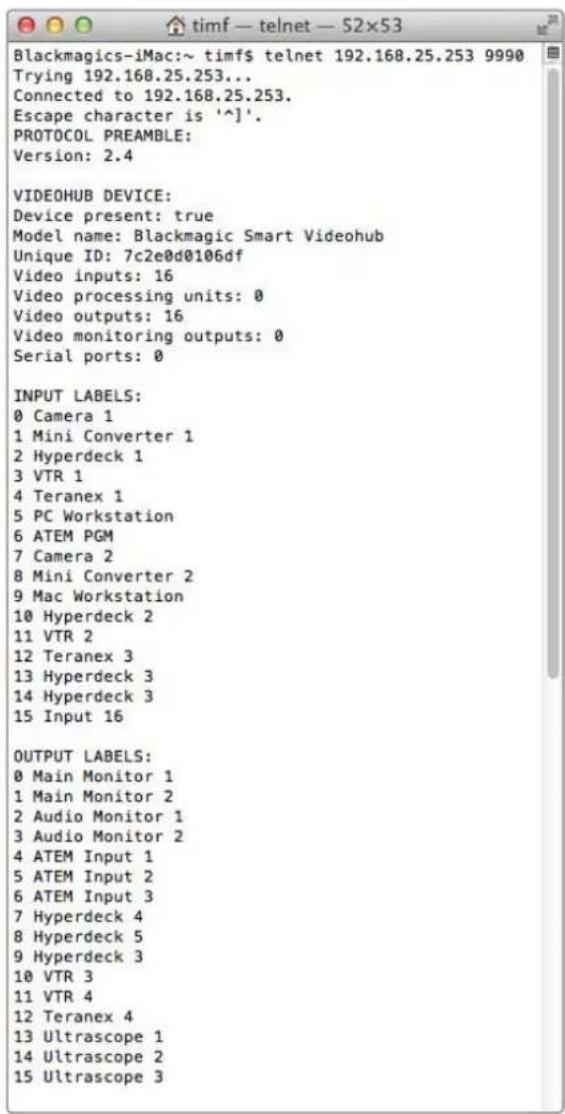
Saving Labels
1 Open the Terminal application which is located within the Applications > Utilities folder.
2Type in "telnet" and a space followed by the IP of your Videohub, then another space and "9990", which is the default port number. For example type: telnet 192.168.25.253 9990. The Protocol Preamble screen will appear.
3Copy the INPUT LABELS: text including the heading and paste into a word processor or simple text editor. Name this file "input labels" and save to your favorite location.
4Copy the OUTPUT LABELS: text including the heading and paste into a word processor or simple text editor. Name this file "output labels" and save to your favorite location.
5Close the telnet session by exiting the terminal window.
Loading Labels
1 Open the Terminal application with is located within the Applications > Utilities folder.
2Type in "telnet" and a space followed by the IP of your Videohub, then another space and "9990", which is the default port number. For example type: telnet 192.168.25.253 9990. The Protocol Preamble screen will appear.
3Open the "input labels" text file in your text editing program and copy the INPUT LABELS: text.
4 Paste this into the telnet session and press "return" twice. Telnet will respond with "ACK" and Videohub will update the input labels.
5Open the "output labels" text file in your text editing program and copy the OUTPUT LABELS: text.
6 Paste this into the telnet session and press "return" twice. Telnet will respond with "ACK" and Videohub will update the output labels.
7Close the telnet session by exiting the terminal window.
Saving and Loading Labels with Telnet in Windows
While you can save and load labels within Blackmagic Videohub Setup, you may also download and use PuTTY which is a free telnet client.
Setting up PuTTY
1 Start the application and in the "Host Name" field, type the IP of your Videohub and in the "Port" field type "9990", which is the default port number.
2From the Connection type options select the "Telnet" radio button.
3Select the "Terminal" tab and tick the "Implicit CR in every LF" checkbox.
4 Click the "Session" tab and save your session parameters by entering a name in the "Saved Sessions" field and clicking the "Save" button.
Saving Labels
1 Double click the PuTTY icon to start the application. Select your saved session from the list and click the "Load" button followed by the "Open" button. The Protocol Preamble screen will appear.
2Copy the INPUT LABELS: text including the heading and paste into a word processor or simple text editor. Name this file "input labels" and save to your favorite location.
3Copy the OUTPUT LABELS: text including the heading and paste into a word processor or simple text editor. Name this file "output labels" and save to your favorite location.
4Exit the telnet session by closing the PuTTY window.
Loading Labels
1 Double click the PuTTY icon to start the application. Select your saved session from the list and click the "Load" button followed by the "Open" button. The Protocol Preamble screen will appear.
2Open the "input labels" text file in your text editing program and copy the INPUT LABELS: text.
3 Right click in the PuTTY session to paste the copied section and press "Enter" twice. PuTTY will respond with "ACK" and Videohub will update the input labels.
4 Open the "output labels" text file in your text editing program and copy the OUTPUT LABELS: text.
5 Right click in the PuTTY session to paste the copied section and press "Enter" twice. PuTTY will respond with "ACK" and Videohub will update the output labels.
6Exit the telnet session by closing the PuTTY window.
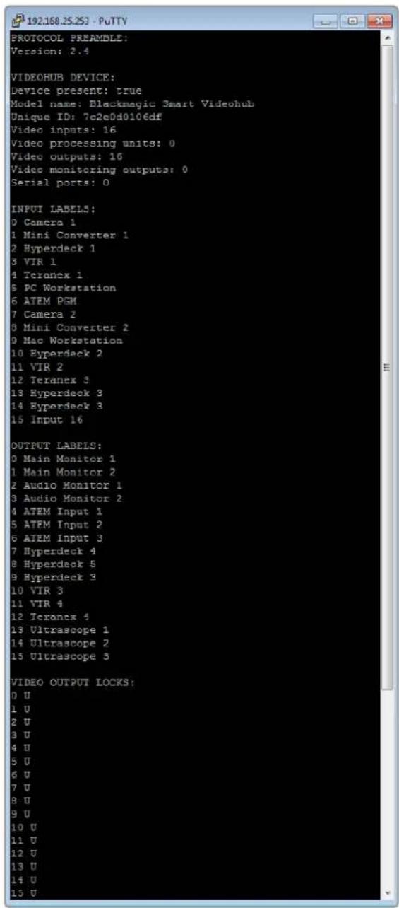
-3G-SDI:PL-4F20-311C

Blackmagic GPI and Tally Interface

Prezado cliente,
Obrigado por adquirir o Videohub!
GPI and Tally Interface 874
Software Blackmagic Videohub 875
Blackmagic Videohub Setup 875
Rotular Entradas e Saidas 876
Saving and Loading Labels
with Telnet in Mac OS 914
Saving and Loading Labels
with Telnet in Windows 915
1 Conecte as fontes de video as entradas SDI do Videhub.
2 Conecte os equipamentos de destino as entradas e saidas SDI do Videohub.
Muito bem! Seu Universal Videohub 288 already started to prepare for some more videos.
GPI and Tally Interface
Number of Destinations
Momentary Hold Video
Instalar a GPI and Tally Interface
Configurar a GPI and Tally Interface
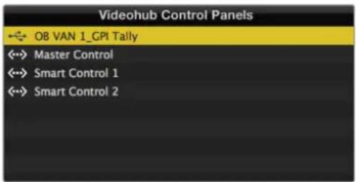
GPI and Tally Interface conectada via USB.
The Blackmagic Videohub Ethernet Protocol is a text based protocol that is accessed by connecting to TCP port 9990 on a Videohub Server. Integrated Videohub Servers and Videohub Server computers are supported by the protocol.
The Videohub Server sends information in blocks which each have an identifying header in all-caps, followed by a full-colon. A block spans multiple lines and is terminated by a blank line. Each line in the protocol is terminated by a newline character.
Upon connection, the Videohub Server sends a complete dump of the state of the device. After the initial status dump, status updates are sent every time the Videohub status changes.
To be resilient to future protocol changes, clients should ignore blocks they do not recognize, up to the trailing blank line. Within existing blocks, clients should ignore lines they do not recognize.
Version 2.3 of the Blackmagic Videohub Ethernet Protocol was released with Videohub 4.9.1 software.
Protocol Preamble
The first block sent by the Videohub Server is always the protocol preamble:
PROTOCOL PREAMBLE:
Version: 2.3
The version field indicates the protocol version. When the protocol is changed in a compatible way, the minor version number will be updated. If incompatible changes are made, the major version number will be updated.
Device Information
The next block contains general information about the connected Videohub device. If a device is connected, the Videohub Server will report the attributes of the Videohub:
VIDEOHUB DEVICE:
Device present: true
Model name: Blackmagic Smart Videohub
Video inputs: 16
Video processing units: 0
Video outputs: 16
Video monitoring outputs: 0
Serial ports: 0
This example is for the Smart Videohub which is a 16x16 router.
If the Videohub Server has no device connected, the block will simply be:
VIDEOHUB DEVICE:
Device present: false
If a device is present, but has an incompatible firmware, the status reported will be:
VIDEOHUB DEVICE:
Device present: needs update
In the last two situations, no further information will be sent, unless the situation is rectified.
If the Videohub Server detects a new Videohub attached, it will resend all blocks except the protocol preamble to indicate the device has changed, and allow the client to update its cache of server state.
Initial Status Dump
The next four blocks enumerate the labels assigned to the input, output, monitoring and serial ports.
Videohubs that do not have monitoring or serial ports do not send the corresponding blocks.
INPUT LABELS:
0VTR1
1 VTR 2
解法1
OUTPUT LABELS:
0 Output feed 1
1 Output feed 2
中中
MONITORING OUTPUT LABELS:
0 Monitor feed 1
1 Monitor feed 2
图10-2
←
SERIAL PORT LABELS:
0 Deck 1
1 Deck 2
NOTE Ports are always numbered starting at zero in the protocol which matches port one on the chassis.
The next three blocks describe the routing of the output, monitoring and serial ports.
VIDEO OUTPUT ROUTING:
0 5
1 3
...
VIDEO MONITORING OUTPUT ROUTING:
0 7
1 8
...
SERIAL PORT ROUTING:
0 12
1 11
...
Videohubs with processing units (only the Workgroup Videohub) send an extra routing block:
PROCESSING UNIT ROUTING:
0 5
1 3
…
Video hubs with frame buffers (only the Workgroup Videohub) send two extra blocks:
FRAME LABELS:
0 Frame one
1 Frame two
...
<1>
FRAME BUFFER ROUTING:
0 7
1 8
...
The next three blocks describe the locking status of the output, monitoring and serial ports. Each port has a lock status of "O" for ports that are owned by the current client (i.e., locked from the same IP address), "L" for ports that are locked from a different client, or "U" for unlocked. Note that Video hubs that do not have monitoring ports or serial ports do not send the corresponding blocks.
Videohubs with processing units (only the Workgroup Videohub) send an extra lock block:
PROCESSING UNIT LOCKS:←
0 U1 UU…
Videohubs with frame buffers (only the Workgroup Videohub) send an extra lock block:
FRAME BUFFER LOCKS:
0 U
1 U
...
Videohubs with serial ports next send a block which describes the direction of each serial port. Each port has a direction of either "control" for the "In (Workstation)" setting, "slave" for "Out (Deck)", or "auto" for "Automatic".
SERIAL PORT DIRECTIONS:
0 control
1 slave
2 auto
...
Videohubs with pluggable cards (only Universal Videohubs) send three more blocks that describe the hardware status of the ports. Missing video or serial ports have a status of "None"; input and output video ports will be "BNC" or "Optical" if they are present; serial ports will be "RS422" if they are present.
VIDEO INPUT STATUS:
0 BNC
1 BNC
VIDEO OUTPUT STATUS:
0 BNC
1 BNC
...
SERIAL PORT STATUS:
0 RS422
1 RS422
Status Updates
When any route, label, or lock is changed on the Videohub Server by any client, the Videohub Server resends the applicable status block, containing only the items that have changed. For example, if serial port 6 has been unlocked, the following block will be sent:
SERIAL PORT LOCKS:
5 U
←
If multiple items are changed, multiple items may be present in the update: OUTPUT LABELS:
7 New output 8 label
10 New output 11 label
If a card is plugged into or removed from the Universal Videohub, it will send hardware status blocks for the video inputs, video outputs, and serial ports on that card.
Requesting Changes
To update a label, lock or route, the client should send a block of the same form the Videohub Server sends when its status changes. For example, to change the route of output port 8 to input port 3, the client should send the following block:
VIDEO OUTPUT ROUTING:
7 2
The block must be terminated by a blank line. On receipt of a blank line, the Videohub Server will either acknowledge the request by responding:
ACK
or indicate that the request was not understood by responding:
NAK
After a positive response, the client should expect to see a status update from the Videohub Server showing the status change. This is likely to be the same as the command that was sent, but if the request could not be performed, or other changes were made simultaneously by other clients, there may be more updates in the block, or more blocks. Simultaneous updates could cancel each other out, leading to a response that is different to that expected.
In the absence of simultaneous updates, the dialog expected for a simple label change is as follows:
OUTPUT LABELS:
6 new output label seven
ACK
OUTPUT LABELS:
6 new output label seven
The asynchronous nature of the responses means that a client should never rely on the desired update actually occurring and must simply watch for status updates from the Videohub Server and use only these to update its local representation of the server state.
To lock a port, send an update to the port with the character "O" indicating that you wish to lock the port for example:
SERIAL PORT LOCKS:
7 O
←
ACK
←
SERIAL PORT LOCKS:
7 O
To forcibly unlock a port that has been locked by another client, send an update to the port with the character "F" instead of using the usual unlock character "U". For example, to override a lock on port 7:
SERIAL PORT LOCKS:
7 F
ACK
SERIAL PORT LOCKS:
7 U
Hardware status blocks can only be sent by the Videohub Server. If a client sends hardware status blocks, they will be ignored.
Requesting a Status Dump
The client may request that the Videohub Server resend the complete state of any status block by sending the header of the block, followed by a blank line. In the following example, the client requests the Videohub Server resend the output labels:
OUTPUT LABELS:
ACK
OUTPUT LABELS:
0 output label 1
1 output label 2
2 output label 3
...
Checking the Connection
While the connection to the Videohub Server is established, a client may send a special no-operation command to check that the Videohub Server is still responding:
PING:
If the Videohub Server is responding, it will respond with an ACK message as for any other recognized command.
Videohub RS-422 Protocol
General
The RS-422 protocol can be used to control many Videohub models as RS-422 slave devices, for router crosspoint switching. This feature is available on any Videohub model with an "RS-422 Control" port.
Depending on your model of Videohub, the RS-422 port may be either a DB9 or RJ11 connector. DB9 cables are commonly available in electrical stores. The RJ11 connector is the same used in many landline telephone connections. By modifying an RS-422 to USB adapter cable terminated with an RJ11 connector you can control Videohub using external controllers via USB.
In "Leitch Server" mode, these Videohub models implement the router (server) side of the Leitch Serial Pass-Through Protocol as specified in section 4 of Leitch document SPR-MAN revision D. In "Leitch Client" mode, the Videohub implements the controller (client) side of the Leitch terminal protocol.
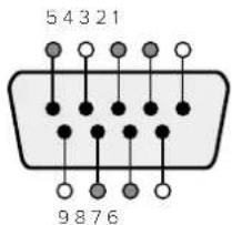
| Pin Function | |
| 1 Ground | |
| 2 Tx- (Data sent by router) | |
| 3 Rx+ (Data received by router) | |
| 4 Ground | |
| 5 NC (No connect) | |
| 6 Ground | |
| 7 Tx+ (Data sent by router) | |
| 8 Rx- (Data received by router) | |
| 9 Ground |
Videohub RS-422 Router Control DB9 pin connections.
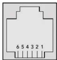
| Pin No. Function | |
| Pin 1 | TX + |
| Pin 2 | TX - |
| Pin 3 | GND |
| Pin 4 | GND |
| Pin 5 | RX - |
| Pin 6 | RX + |
Videohub RS-422 Router Control RJ11 pinout diagram.
This document describes the commands and parameters in the protocol that are relevant and supported by Videohub. Other commands and parameters specified in the Leitch protocol are accepted but ignored.
The RS-422 serial port is configured as 9600 N81.
The protocol is line-oriented, with a maximum length of 250 characters per command. Each command from the client should be terminated with a carriage-return (r). Each response from the server will be terminated with a carriage-return and line-feed (r\n).
Sources, destinations and levels are always specified in base-16, numbered from zero. Levels are always between 0 and 15 ("F"). Videohubs only have one valid level - level zero.
On connecting to the serial port, the client should send a carriage-return. The Videohub Server will respond with a > character prompt, which is not followed by a carriage-return or line-feed. Receiving the prompt indicates that a connection has been established. The same prompt will be issued after each command received by the Videohub Server.
In the following documentation, commands in orange and values in blue must be typed literally, including any spaces. In the following example of an immediate command using destination port 7 and source port 3, @ X:0/destination, source would be entered as: @ X:0/6,2
Notifications
Once connected, if status reporting is enabled, the client will receive a notification message when a route changes on the Videohub Server. The notifications take one of two forms:
S:0destination,source Routing change
This message indicates that the specified source port is now routed to the specified destination.
V:0destination,source Preset routing notification
This message indicates that the current preset includes a route from the specified source to the specified destination.
Global Commands
All pass-through commands are preceded by an 品 symbol and a space.
The following client commands are supported:
品 disable status reporting
Status reporting is disabled by default.
? enable status reporting
Status reporting is enabled.
@ Z: reset routing table
Routing is reset so that the first source is routed to all destinations.
Immediate Commands
X:0/destination,source change route
@ X:0/destination,source/destination-2,source-2... change multiple routes
The specified source ports are routed to the specified destinations.
Any routing changes will trigger S: notifications.
@ X?Odestination request individual route status
The source routed to a the specified destination will be returned as an S: notification.
@ S?0 request all ports route status
Each source & destination port pair will be returned as S: notifications
Salvo Commands
P:0/destination,source queue route change
@ P:0/destination,source/destination-2,source-2... queue multiple route changes
The specified routing changes are added to the current salvo for later execution.
@ P?Odestination request individual port status in salvo
If a routing change for the specified destination port is queued, the route will be returned as
aV: notification,
@ V?0 request all ports status in salvo
Each queued routing change in the salvo is reported as a v: notification.
B:C clear salvo
B:R clear salvo
Any queued changes are discarded and the salvo is reset.
B:E execute salvo
Any queued changes are executed and each routing change will be returned as an S:
notification.
Saving and Loading Labels with Telnet in Mac OS
Normally you would use Blackmagic Videohub Setup to save and load labels between different Videohub routers and to backup your videohub settings. However, if for any reason you wish to use the Terminal, the instructions below let you save and load router label configurations via the Terminal.
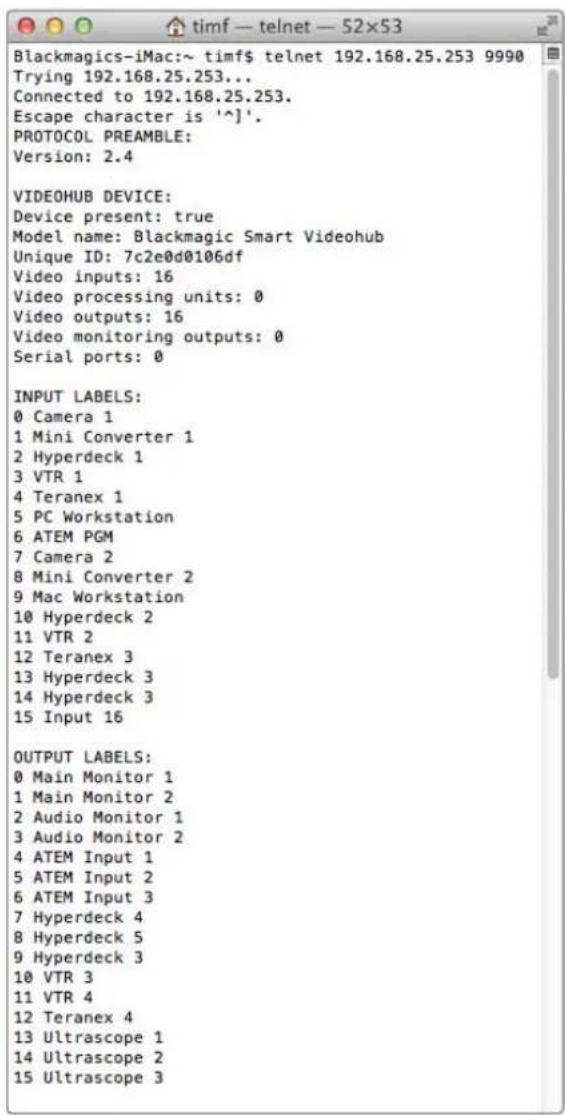
Saving Labels
1 Open the Terminal application which is located within the Applications > Utilities folder.
2Type in "telnet" and a space followed by the IP of your Videohub, then another space and "9990", which is the default port number. For example type: telnet 192.168.25.253 9990. The Protocol Preamble screen will appear.
3 Copy the INPUT LABELS: text including the heading and paste into a word processor or simple text editor. Name this file "input labels" and save to your favorite location.
4Copy the OUTPUT LABELS: text including the heading and paste into a word processor or simple text editor. Name this file "output labels" and save to your favorite location.
5Close the telnet session by exiting the terminal window.
Loading Labels
1 Open the Terminal application with is located within the Applications > Utilities folder.
2Type in "telnet" and a space followed by the IP of your Videohub, then another space and "9990", which is the default port number. For example type: telnet 192.168.25.253 9990. The Protocol Preamble screen will appear.
3 Open the "input labels" text file in your text editing program and copy the INPUT LABELS: text.
4 Paste this into the telnet session and press "return" twice. Telnet will respond with "ACK" and Videohub will update the input labels.
5Open the "output labels" text file in your text editing program and copy the OUTPUT LABELS: text.
6 Paste this into the telnet session and press "return" twice. Telnet will respond with "ACK" and Videohub will update the output labels.
7Close the telnet session by exiting the terminal window.
Saving and Loading Labels with Telnet in Windows
While you can save and load labels within Blackmagic Videohub Setup, you may also download and use PuTTY which is a free telnet client.
Setting up PuTTY
1 Start the application and in the "Host Name" field, type the IP of your Videohub and in the "Port" field type "9990", which is the default port number.
2From the Connection type options select the "Telnet" radio button.
3Select the "Terminal" tab and tick the "Implicit CR in every LF" checkbox.
4 Click the "Session" tab and save your session parameters by entering a name in the "Saved Sessions" field and clicking the "Save" button.
Saving Labels
1 Double click the PuTTY icon to start the application. Select your saved session from the list and click the "Load" button followed by the "Open" button. The Protocol Preamble screen will appear.
2 Copy the INPUT LABELS: text including the heading and paste into a word processor or simple text editor. Name this file "input labels" and save to your favorite location.
3Copy the OUTPUT LABELS: text including the heading and paste into a word processor or simple text editor. Name this file "output labels" and save to your favorite location.
4Exit the telnet session by closing the PuTTY window.
Loading Labels
1 Double click the PuTTY icon to start the application. Select your saved session from the list and click the "Load" button followed by the "Open" button. The Protocol Preamble screen will appear.
2 Open the "input labels" text file in your text editing program and copy the INPUT LABELS: text.
3 Right click in the PuTTY session to paste the copied section and press "Enter" twice. PuTTY will respond with "ACK" and Videohub will update the input labels.
4 Open the "output labels" text file in your text editing program and copy the OUTPUT LABELS: text.
5 Right click in the PuTTY session to paste the copied section and press "Enter" twice. PuTTY will respond with "ACK" and Videohub will update the output labels.
6Exit the telnet session by closing the PuTTY window.
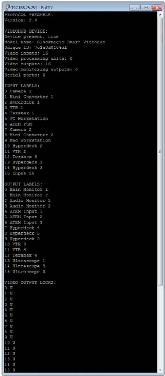
Substituir ama ventoinha no Universal Videohub
-3G-SDI:PL-4F20-311C

Blackmagic GPI and Tally Interface

Hos Geldiniz
Blackmagic Design CEO
icindekiler
Blackmagic Videohub ile Taniin 925
Baslarken 928
Saving and Loading Labels
with Telnet in Mac OS 1006
Saving and Loading Labels
with Telnet in Windows 1007
Kirmizi "alarm" LED lambasi
Do not unplug this Videohub while the update is in progress.
33%
Guncelleme islemdevam ederken,Videohub cihazinin fisini prizden sikarmayin
Blackmagic Videohub Control
| "Select Videohub" (Videohub Sec) | <···> | Ağınıza®,®,®,®,®,®,®,®,®,®,®,®,®,®,®,®,®,®,®,®,®,®,®,®,®,®,®,®,®,®,®,®,®,®,®,®,®,®,®,®,®,®,®,®,®,®,®,®,®,®,®,®,®,®,®,®,®,®,®,®,®,®,®,®,®,®,®,®,®,®,®,®,®,®,®,®,®,®,®,®,®,®,®,®,®,®,®,®,®,®,®,®,®,®,®,®,®,®,®,®,®, seçiminizi,—yapın. |
| Save Layout (Düzeni Kaydet) | ★ | Videohub cihazın®,®,®,®,®,®,®,®,®,®,®,®,®,®,®,®,®,®,®,®,®,®,®,®,®,®,®,®,®,®,®,®,®,®,®,®,®,®,®,®,®,®,®,®,®,®,®,®,®,®,®,®,®,®,®,®,®,®,®,®,®,®,®,®,®,®,®,®,®,®,®,®,®,®,®,®,®,®,®,®,®,®,®,®,®,®,®,®,®,®,®,®,®,®,®,®,®,®,®, ® |
| Load Layout (Düzeni Yükle) | ↓ | Daha®, önceden kaydett®,®,®,®,®,®,®,®,®,®,®,®,®,®,®,®,®,®,®,®,®,®,®,®,®,®,®,®,®,®,®,®,®,®,®,®,®,®,®,®,®,®,®,®,®,®,®,®,®,®,®,®,®,®,®,®,®,®,®,®,®,®,®,®,®,®,®,®,®,®,®,®,®,®,®,®,®,®,®,®,®,®,®,®,®,®,®,®,®,®,®,®,®,®,®,®,®,®,®,! Dada onceden kaydett®,®,®,®,®,®,®,®,®,®,®,®,®,®,®,®,®,®,®,®,®,®,®,®,®,®,®,®,®,®,®,®,®,®,®,®,®,®,®,®,®,®,®,®,®,®,®,®,®,®,®,®,®,®,®,®,®,®,®,®,®,®,®,®,®,®,®,®,®,®,®,®,®,®,®,®,®,®,®,®,®,®,®,®,®,®,®,®,®,®,®,®,®,®,®,®,® |
| Edit Buttons (Butonlari Düzenle) | ☑ | Arayüz butonlari®,®,®,®,®,®,®,®,®,®,®,®,®,®,®,®,®,®,®,®,®,®,®,®,®,®,®,®,®,®,®,®,®,®,®,®,®,®,®,®,®,®,®,®,®,®,®,®,®,®,®,®,®,®,®,®,®,®,®,®,®,®,®,®,®,®,®,®,®,®,®,®,®,®,®,®,®,®,®,®,®,®,®,®,®,®,®,®,®,®,®,®,®,®,®,®,®,®,®,. göruntüler. |
| Reset All (Hepsini Sifirla) | ◎ | Başlı Videohub cihazınin®,®,®,®,®,®,®,®,®,®,®,®,®,®,®,®,®,®,®,®,®,®,®,®,®,®,®,®,®,®,®,®,®,®,®,®,®,®,®,®,®,®,®,®,®,®,®,®,®,®,®,®,®,®,®,®,®,®,®,®,®,®,®,®,®,®,®,®,®,®,®,®,®,®,®,®,®,®,®,®,®,®,®,®,®,®,®,®,®,®,®,®,®,®,®,®,®,®,®,; ve kılışlerin ve"—çık—islarin"—göruntüler ve"—kılışlerin"—ikonlari"—varsıyanan"—ikonlarla"—degışirir. Kaynak,—he.Def ve deck)—kontrol ayarlan”—muhafaza”—edilir. |
The Blackmagic Videohub Ethernet Protocol is a text based protocol that is accessed by connecting to TCP port 9990 on a Videohub Server. Integrated Videohub Servers and Videohub Server computers are supported by the protocol.
The Videohub Server sends information in blocks which each have an identifying header in all-caps, followed by a full-colon. A block spans multiple lines and is terminated by a blank line. Each line in the protocol is terminated by a newline character.
Upon connection, the Videohub Server sends a complete dump of the state of the device. After the initial status dump, status updates are sent every time the Videohub status changes.
To be resilient to future protocol changes, clients should ignore blocks they do not recognize, up to the trailing blank line. Within existing blocks, clients should ignore lines they do not recognize.

Version 2.3 of the Blackmagic Videohub Ethernet Protocol was released with Videohub 4.9.1 software.
Protocol Preamble
The first block sent by the Videohub Server is always the protocol preamble:
PROTOCOL PREAMBLE:
Version: 2.3
The version field indicates the protocol version. When the protocol is changed in a compatible way, the minor version number will be updated. If incompatible changes are made, the major version number will be updated.
Device Information
The next block contains general information about the connected Videohub device. If a device is connected, the Videohub Server will report the attributes of the Videohub:
VIDEOHUB DEVICE:
Device present: true
Model name: Blackmagic Smart Videohub
Video inputs: 16
Video processing units: 0
Video outputs: 16
Video monitoring outputs: 0
Serial ports: 0
This example is for the Smart Videohub which is a 16x16 router.
If the Videohub Server has no device connected, the block will simply be:
VIDEOHUB DEVICE:
Device present: false
If a device is present, but has an incompatible firmware, the status reported will be:
VIDEOHUB DEVICE:
Device present: needs update
In the last two situations, no further information will be sent, unless the situation is rectified.
If the Videohub Server detects a new Videohub attached, it will resend all blocks except the protocol preamble to indicate the device has changed, and allow the client to update its cache of server state.
Initial Status Dump
The next four blocks enumerate the labels assigned to the input, output, monitoring and serial ports.
Videohubs that do not have monitoring or serial ports do not send the corresponding blocks.
INPUT LABELS:
0VTR1
1 VTR 2
咖啡
OUTPUT LABELS:
0 Output feed 1
1 Output feed 2
特此公告。
←
MONITORING OUTPUT LABELS:
0 Monitor feed 1
1 Monitor feed 2
华中特
←
SERIAL PORT LABELS:
0 Deck 1
1 Deck 2
NOTE Ports are always numbered starting at zero in the protocol which matches port one on the chassis.
The next three blocks describe the routing of the output, monitoring and serial ports.
VIDEO OUTPUT ROUTING:
0 5
1 3
...
< VIDEO MONITORING OUTPUT ROUTING:
0 7
1 8
...
< SERIAL PORT ROUTING:
0 12
1 11
...
Videohubs with processing units (only the Workgroup Videohub) send an extra routing block:
PROCESSING UNIT ROUTING:
0 5
1 3
…
Videohubs with frame buffers (only the Workgroup Videohub) send two extra blocks:
FRAME LABELS:
0 Frame one
1 Frame two
...
<1>
FRAME BUFFER ROUTING:
0 7
1 8
...
The next three blocks describe the locking status of the output, monitoring and serial ports. Each port has a lock status of "O" for ports that are owned by the current client (i.e., locked from the same IP address), "L" for ports that are locked from a different client, or "U" for unlocked. Note that Video hubs that do not have monitoring ports or serial ports do not send the corresponding blocks.
VIDEO OUTPUT LOCKS:
0 U<1

- Languages
- Contents
- Welcome
- Grant Petty
- Introducing Blackmagic Videohub
- Getting Started
- Creating an IP Videohub with Teranex Mini IP Video 12G
- Connecting Power
- Connecting Video
- Controlling your Videohub
- Switching a Route using the Built in Control Panel
- Selecting the Source and Destination
- Shortcut Buttons
- A Note about Shortcut Buttons
- Using the Shortcut Buttons
- Select the Destination
- Select the Source
- Locking and Unlocking Routes
- Connecting Videohub to a Network
- Configuring Network Settings
- Universal Videohub Routers
- Universal Videohub 288
- Universal Videohub 288 Crosspoint Card
- Router Control Cable
- Power Supply
- Building Universal Videohub 288
- Installing a Universal Videohub 288 Crosspoint Card
- Universal Videohub Status LEDs
- A healthy Universal Videohub 288 Crosspoint should display the following:
- Installing Interface cards
- Installing a Universal Videohub Power Supply
- Installing a second Power Supply while Universal Videohub 288 is running
- Removing a Power Supply while Universal Videohub 288 is running
- Universal Videohub 72
- Universal Videohub 72 Crosspoint Card
- Building Universal Videohub 72
- Installing a Universal Videohub 72 Crosspoint Card
- A healthy Universal Videohub 72 Crosspoint should display the following:
- Installing a Universal Videohub 450W Power Card
- SDI Interface Card
- Universal Videohub Interface Cards
- Tips for Connecting SDI cables
- Universal Videohub Deck Control Cable
- Smart Videohub CleanSwitch 12x12
- Videohub Hardware Control Panels
- Videohub Master Control Pro
- Videohub Smart Control Pro
- Configuring the Control Panel
- Connecting to an Ethernet Network
- Control Panel Button Diagnostics
- Pink Flashing Light
- Red Flashing Light
- Yellow Flashing Light
- No Flashing Light
- About Routing Levels
- SDI 422
- SDI
- 422
- How to Select Sources and Destinations
- Selecting units by typing the Videohub port numbers
- Selecting Units using the Scroll Wheel
- Selecting Units using Customizable Buttons and the Scroll Wheel
- Selecting Units using Numeric Buttons and the Scroll Wheel
- Selecting Units using Both Customizable and Numeric Buttons
- Using Macros
- Using Videohub Smart Control Pro as a Cut-Bus Controller
- Using Videohub Smart Control Pro as an XY Controller
- Labeling Pushbuttons
- Blackmagic MultiView 16
- Using the Control Panel
- LCD and Home Screen
- HD video output format
- Audio input
- Multiview layout
- Control Buttons
- SRC and VIEW
- SOLO
- SET
- MENU
- NUMBERS
- SRC, VIEW and SET
- SOLO and MENU
- GPI and Tally Interface
- Blackmagic Videohub Software
- Blackmagic Videohub Setup
- Labeling Inputs and Outputs
- Setting Outputs to Cut Bus Mode
- Creating Macros
- Button Mapping
- Setup Settings
- Video Monitoring
- Network
- Reset
- Updating your Videohub
- Blackmagic Videohub Control
- Selecting a Videohub
- Adding Pushbuttons
- Viewing Routes
- Switching Routes
- Edit Buttons
- Using Pushbuttons
- Viewing and Switching Routes
- Use TAKE Confirmation before Switching Routes
- Serial Control Settings
- Touchscreen Computers
- Apple iPad
- The initial Pushbutton interface
- Configuring Videohub Pushbuttons on the iPad
- Viewing and Changing Routes
- Installing the Videohub Software on iPad
- Controlling Blackmagic MultiView 16
- Connecting Blackmagic MultiView 16 to Videohub Control Software
- Configuring Network Settings on Blackmagic MultiView 16
- To configure your network settings:
- Videohub Hardware Panel Setup
- Network Settings
- Add Videohub Control
- Load/Save Settings
- Configuring Videohub Master Control Pro
- Backlight
- Creating Button Labels
- Configuring Videohub Smart Control Pro
- Number of Destinations
- Cut Bus Configuration
- XY Controller Configuration
- Number of Macros
- Take Button
- Configuring GPIs
- Latch Video
- Momentary Hold Video
- Configuring Tally
- GPO Match
- Daisy Chaining Multiple GPI and Tally Interfaces
- Adding a GPI and Tally Interface Over a Network
- Setting up the GPI and Tally Interface
- Configuring the GPI and Tally Interface
- Developer Information
- Blackmagic Videohub Ethernet Protocol v2.3
- Summary
- Protocol Preamble
- Device Information
- Initial Status Dump
- Status Updates
- Requesting Changes
- Requesting a Status Dump
- Checking the Connection
- Videohub RS-422 Protocol
- General
- Notifications
- Global Commands
- Immediate Commands
- Salvo Commands
- Saving and Loading Labels with Telnet in Mac OS
- Saving Labels
- Loading Labels
- Saving and Loading Labels with Telnet in Windows
- Setting up PuTTY
- Replacing a fan in Universal Videohub
- Help
- Getting Help
- Blackmagic Design online support pages
- Blackmagic Design Forum
- Contacting Blackmagic Design support
- Checking the version currently installed
- How to get the latest updates
- Regulatory Notices
- Disposal of Waste of Electrical and Electronic Equipment Within the European Union.
- ISED Canada Statement
- Safety Information
- State of California statement
- Warning for Authorized Service Personnel
- Caution - Double Pole/Neutral Fusing
- Warranty
- Limited Warranty
- Blackmagic
- Videohub
- はこ
- 目次
- Initial StatusDump
- StatusUpdates
- RequestingaStatusDump
- CheckingtheConnection
- VideohubRS -422Protocol
- GlobalCommands
- ImmediateCommands
- SalvoCommands
- SavingLabels
- LoadingLabels
- SettingupPuTTY
- UniversalVideohubのPFNの取り外し
- Chere cliente, cher client,
- Alimentation
- Willkommen
- Inhaltsverzeichnis
- Blackmagic Design Online-Support
- California Proposition 65
- Bienvenido
- Índice
- LEGEND
- BlackmagicVideohub简介
- 设置GPI and Tally Interface
- 配置GPI and Tally Interface
- 更换Universal Videohub的风扇
- 加利福尼亚安全声明
- 目录
- 目录键
- s
- StKJeHJIeJU
- SAUGAJITGRTBNTIeSsKTOHJUHAGHJUHJUHJUHJUHJUHJUHJUHJUHJUHJUHJUHJUHJUHJUHJUHJUHJUHJUHJUHJUHJUHJUHJUHJUHJUH
- GPIandTallyInterface
- ViDIO MONI TERLIG
- NeTrw
- SettingupPuity
- 策拉托尼阿孕
- 公在
- YBaKaembl Nolb3OBaTeJIb!
- Ppant Nettn
- CopepxaHne
- Hobinka Blackmagic Videohub
- Повтовka к paбote
- Co3dAnHe cepBepa IP Videohub c nOmoBIO KOHBeptepa Teranex Mini IP Video 12G
- NodkloucheHne nTaHn
- NodkloueHne nCTOuHKnOB Bndeo
- Bb6op nctouHnka
- Бл Okи探测ка и разблOkи探测ка Наразвленners Mapштунзацни
- MoHTax KOMMyTaTopa Universal Videohub 288
- YcTaHOBka KOMMyTaUHHO MaTpncbI Universal Videohub 288 Crosspoint
- CBeToIIOHbIe HnIkaTOpbl coCTOHNHa Universal Videohub
- YctaHOBka nHTeppeiChbIX nIaT
- YctaHOBka nlaTbI nHTaHn Universal Videohub 450W Power Card
- HntepeienchbIe SDI-nlaTbi
- Bb6op nCTouHnKOB npneMHnKOB cnHaJa
- Bb6op yctpoCTB BBOOM Homepa npTa Ha Videohub
- Bb6op yctpoiCTB c nOmoIbu KpyrIou pyuKn
- Bb6op yctpoiCTB c NOMOIO HacTpaNBAeMbIX KHOJOK IN KpyrnoI pyKn
- Bb6op yctpoiCTB c nOMoIbIO KHOJOK C uIΦpaMn I kpyrIo npyKn
- Bb6op yctpoiCTB c nOMOuHactpaBaembIX KHOIOK IN KOHOOK C uΦpamN
- KK-dncnneuHaayabhaCtpaHua
- ΦopMaT HD-BnDeo Ha BbIXOe
- AynOBXoA
- KoHpypaunMHOOROKOHOROMHTOPnHa
- KhONKn ynpabBHeHn
- SRC (NCTOCHNK) N VIEW (OKHO)
- SOLO (Cono)
- SET(YctaHOBntb)
- MENU (MeHIO)
- KhONkncuΦpamn
- SRC (NctouhMK), VIEW (Okho) n SET (YctahOBtB)
- SOLO (Coi) MENU (MeHIO)
- ПО Blackmagic Videohub
- BbI6oppeXIMa npMOro nepeKIOueHmexy BbIXOaMn
- C03dahne MaKpOKOMaHd
- Ha3haeHne KhoNok
- OchOBhIe HacTpoiKN
- Onzna Video monitoring
- Network (CeTb)
- Reset (C6poc)
- Ов然是 IO kommyTaTopa Videohub
- BbI6op kOMMyTaTopa Videohub
- O6aBHeHne KHOHOK
- PpocmToHnPaBHeHnMaPspTy3aCn
- I3meHeHne HappaBleHnmaPspTytn3aun
- Pa60Ta C KHOKNKAMN
- HactpoKa ceTeBbIX npaMeTpoB Ha Blackmagic MultiView 16
- Iopraok HactpoKn ceteBbix npaMeTpO8
- CeteBbIe npaMeTpbl
- D6abHeHne naHn ynpaBHeHna Videohub
- 3arpy3ka n coxpaHHe HacTpoek
- Hacrtpoika панели Videohub Master Control Pro
- POncBetka
- Co3dahne npbIKOB KHOIOK
- Hactpoika paheN Videohub Smart Control Pro
- YncIIO npneMnKOB cnHaJa
- Hactpoika pekimama npramoro nepekliouateia
- HactpoKa nepeKluueHnB Dba shara
- YncnoMaKpocOB
- Khonka TAKE
- HactpoynKa KOHTaKToB GPI
- Latch Video (Фиксаньдю)
- Momentary Hold Video (KpaTKOBpeMeHHbI npocMoTp)
- Hac troka Tally-ндикции
- GPO match (Приимен综合体 GPO)
- PocleioBatebHoe coeHHHe Heckobkx yctpoCTB GPI and Tally Interface
- Добavenhoe yctpoctba GPI and Tally Interface no cetn
- UctaHOBka yctpoiCTBa GPI and Tally Interface
- HactpoJa yctpoiCTBa GPI and Tally Interface
- COOTBETCTBNE Tpe6oBaHnIaM ISED (KaHaDa)
- ПразвILA 6e3ОпасноCTN
- YBeDomJIeHne dIg XHTeIe Wtata KaIIΦOpHnIa
- PpeDynpexdeneIe IeyHueckoro nepcoHaJa
- OcToPoxHo: nIaBKn npedoxpaHnte bDByxNIOChb/N HeHTpAn
- Гаразня
- OrpaHnueHHa rapaHTna
- Gentile utente
- Indices
- Collegare a Cascata diversi GPI and Tally Interface
- Configurare GPI and Tally Interface
- Prezado cliente,
- Instalar a GPI and Tally Interface
- Configurar a GPI and Tally Interface
- Substituir ama ventoinha no Universal Videohub
- Hos Geldiniz
- icindekiler
Brand : Blackmagic Design
Model : Universal Videohub 72
Category : Router