T150 Pro - Game wheel THRUSTMASTER - Free user manual and instructions
Find the device manual for free T150 Pro THRUSTMASTER in PDF.

| Product Type | Force Feedback Racing Wheel |
| Brand | Thrustmaster |
| Model | T150 Pro |
| Weight | 7 kg (wheel and pedal set) |
| Power Supply | 220-240 V, 50 Hz, 0.8 A (European version) or external power adapter (other regions) |
| Rotation Angle | 1080 degrees |
| Compatibility | PlayStation 3, PlayStation 4, PC (with drivers) |
| Connectivity | USB, pedal connector, gear shift connector (sold separately) |
| Force Feedback Type | Force Feedback |
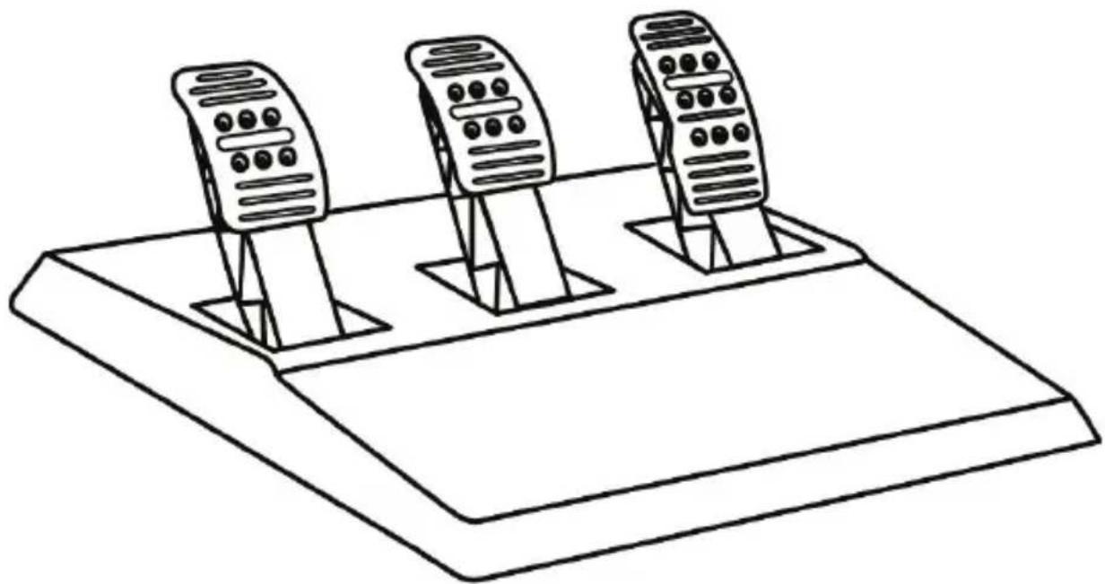
| Pedal Set | 3 pedals with height, spacing and tilt adjustments |
| Mounting System | Metal clamp with mounting system for table or desk |
| Firmware Update | Yes, via PC on support.thrustmaster.com |
| Main Material | Plastic for base, rubber for rim, metal for pedals |
| Warranty | 2 years in the European Union (according to local legislation) |
| Maintenance | Clean with a soft, dry cloth; do not block ventilation grilles |
| Safety | Do not open the base; do not use barefoot or in socks; be careful of force feedback |
| Included Accessories | Wheel, pedal set, USB cable, power cable, mounting system, 2.5 mm Allen key, conical rubber brake (not installed) |
| Special Features | Electronic pedal inversion (MODE button), automatic calibration, conical rubber brake module for brake |
| Manual Languages | French, English, German, Spanish, Italian, Dutch, Polish, Portuguese, Russian, Turkish, etc. |
Frequently Asked Questions - T150 Pro THRUSTMASTER
User questions about T150 Pro THRUSTMASTER
0 question about this device. Answer the ones you know or ask your own.
Ask a new question about this device
Download the instructions for your Game wheel in PDF format for free! Find your manual T150 Pro - THRUSTMASTER and take your electronic device back in hand. On this page are published all the documents necessary for the use of your device. T150 Pro by THRUSTMASTER.
USER MANUAL T150 Pro THRUSTMASTER
natural_image
Technical line drawing of a mechanical component with concentric rings and mounting holes (no text or symbols)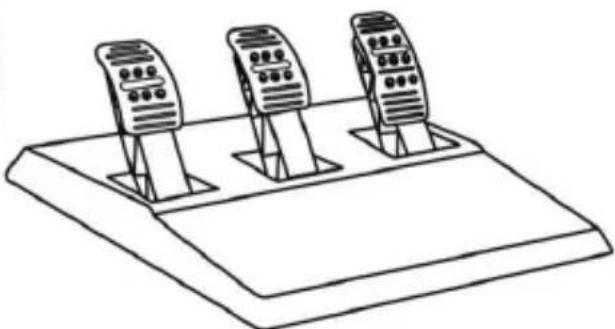
natural_image
Line drawing of three identical mobile phone modules mounted on a base (no text or symbols)WARNING:
To ensure that your T150 racing wheel functions correctly with games, you may be required to install the game's automatic updates (available when your system is connected to the Internet).
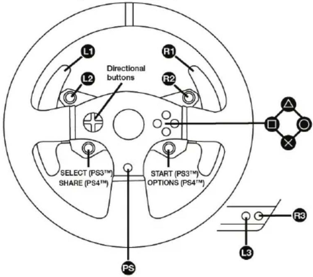
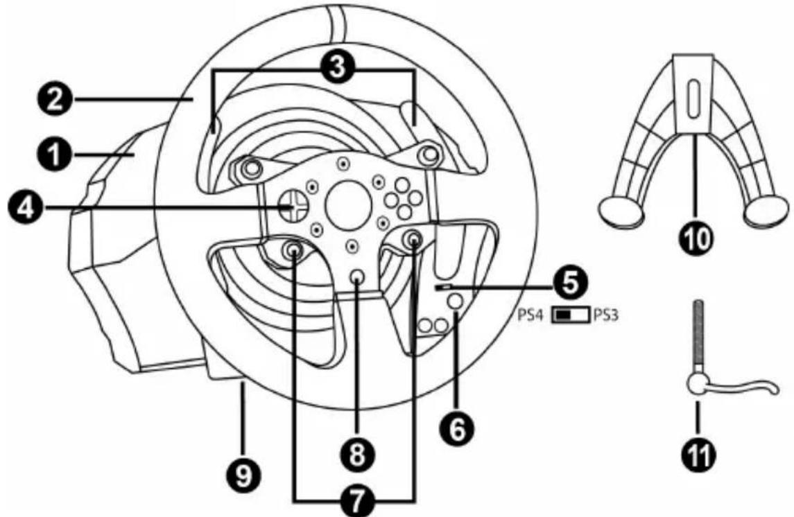
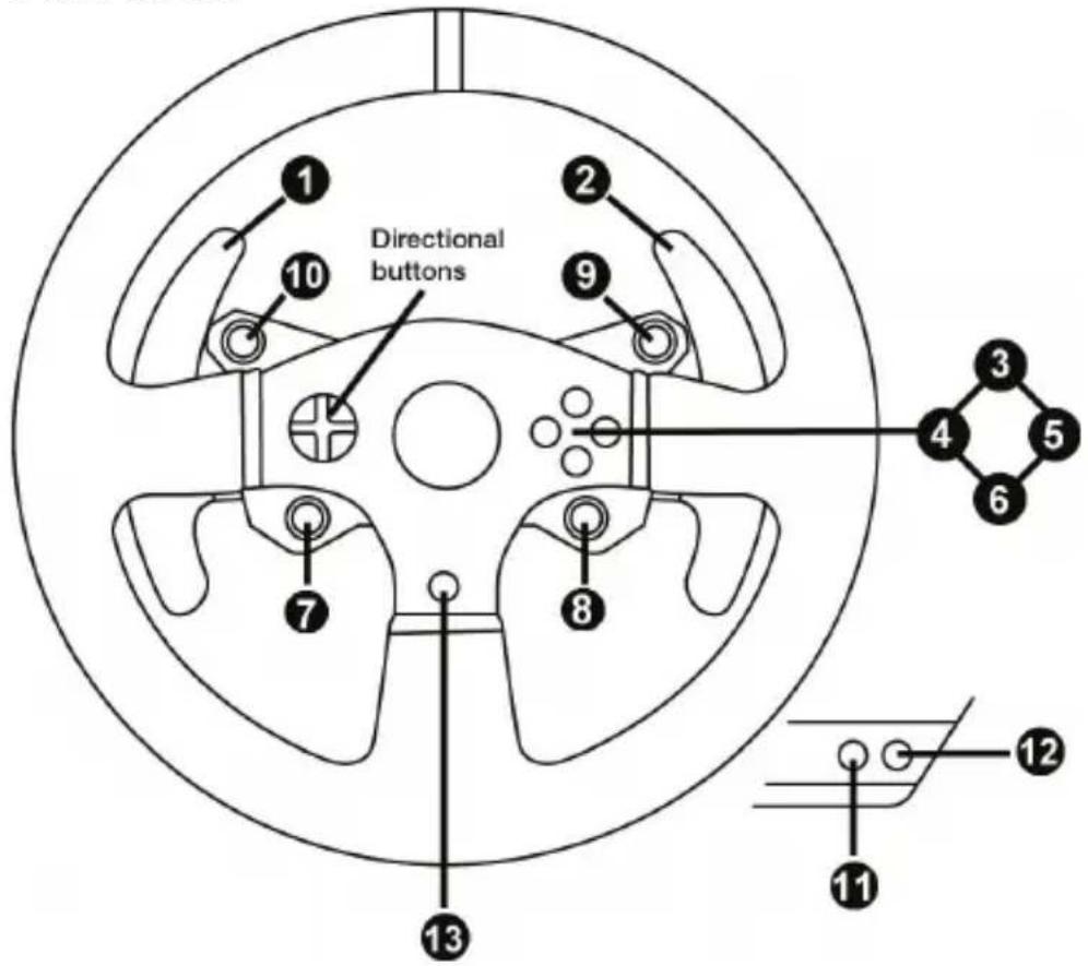
TECHNICAL FEATURES
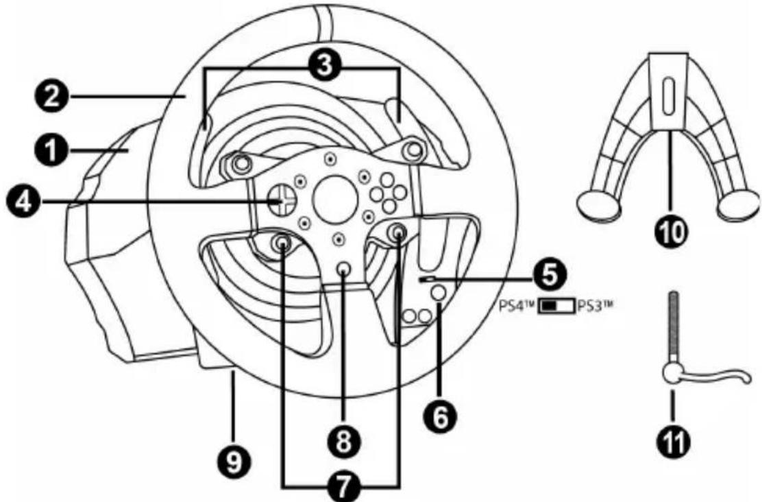
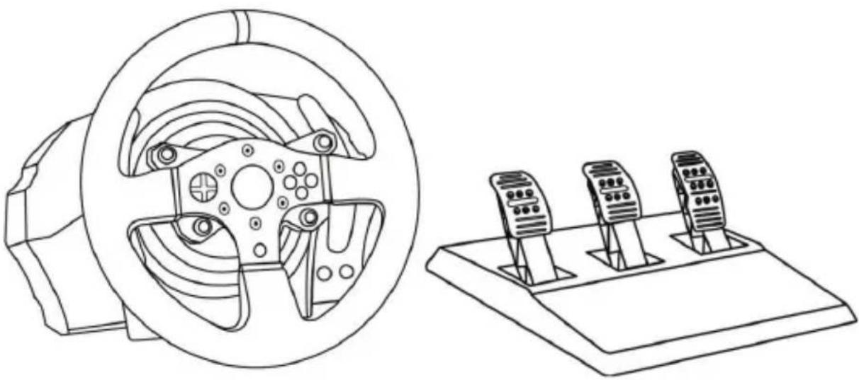
1 T150 base
2 Wheel
3 2 sequential paddle shifters (up & down)
4 Directional buttons
5 Built-in USB sliding switch for PS4 ^TM /PS3 ^TM
6 MODE button + red/green indicator light
7 SELECT/START buttons on PS3 ^™ and SHARE/OPTIONS on PS4 ^™
8 PS button
9 Large threaded hole (for attachment system and fastening screw)
10 Attachment system
11 Metal fastening screw
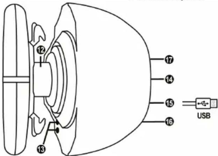
12 Steering axis
13 L3/R3 buttons
14 Power cable
or Power supply connector
(varies from one country to another)
15 Racing wheel USB cable and connector
16 Gearbox connector
(gearbox sold separately)
17 Pedal set connector
PLUGGING THE RACING WHEEL INTO AN ELECTRICAL OUTLET: PLEASE READ BEFORE PROCEEDING!
Your racing wheel's power supply varies according to the country where you purchased your device.
European versions only
Important note: the European version of the T150 is equipped with an internal power supply, located directly inside the racing wheel's base.

- Simply connect the racing wheel's mains connector to a 220V power outlet.
Other versions (non-European)
Note: Contrary to the European version, the non-European T150 features an external power supply; a specific device is provided with the racing wheel.
- Connect the external adapter to the relevant connector located at the back of the racing wheel, then connect the external mains power adapter to a standard power outlet featuring the same voltage.
WARNING
Before using this product, please read this manual carefully and save it for later reference.

Warning – Electrical shock
* Keep the product in a dry location and do not expose it to dust or sunlight.
* Do not twist or pull on the connectors and cables.
* Do not spill any liquid on the product or its connectors.
* Do not short-circuit the product.
* Never dismantle the product; do not throw it onto a fire and do not expose it to high temperatures.
* Do not use a power supply cable other than the one provided with your racing wheel.
* Do not use the power supply cable if the cable or its connectors are damaged, split or broken.
* Make sure that the power supply cable is properly plugged into an electrical outlet, and properly connected to the connector at the rear of the racing wheel's base.
* Do not open up the racing wheel: there are no user-serviceable parts inside. Any repairs must be carried out by the manufacturer, its authorised representative or a qualified technician.
* Only use attachment systems/accessories specified by the manufacturer.
* If the racing wheel is operating abnormally (if it is emitting any abnormal sounds, heat or odours), stop using it immediately, unplug the power supply cable from the electrical outlet and disconnect the other cables.
* If you will not be using the racing wheel for an extended period of time, unplug its power supply cable from the electrical outlet.
* The electrical outlet must be located near the equipment and must be easily accessible.

Air vents
Make sure not to block any of the air vents on the racing wheel's base. For optimal ventilation, make sure to do the following:
* Position the wheel's base at least 10cm away from any wall surfaces.
* Do not place the base in any tight spaces.
* Do not cover the base.
* Do not let any dust build up on the air vents.

For safety reasons, never use the pedal set with bare feet or while wearing only socks on your feet.
THRUSTMASTER® DISCLAIMS ALL RESPONSIBILITY IN THE EVENT OF INJURY RESULTING FROM USE OF THE PEDAL SET WITHOUT SHOES.

Warning – Injuries due to force feedback and repeated movements
Playing with a force feedback racing wheel may cause muscle or joint pain. To avoid any problems:
* Avoid lengthy gaming periods.
* Take 10 to 15 minute breaks after each hour of play.
* If you feel any fatigue or pain in your hands, wrists, arms, feet or legs, stop playing and rest for a few hours before you start playing again.

Warning – Injuries due to force feedback and repeated movements (continued)
* If the symptoms or pain indicated persist when you start playing again, stop playing and consult your doctor.
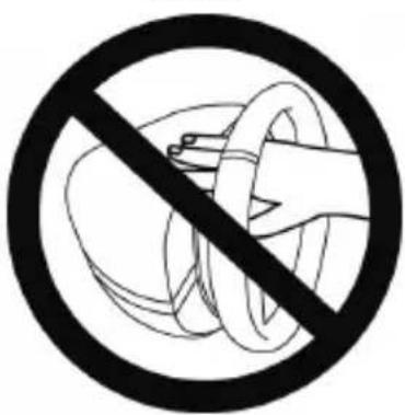
* Keep out of children's reach.
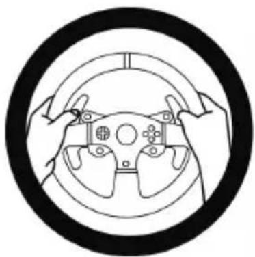
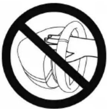
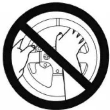
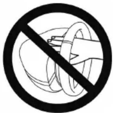
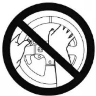
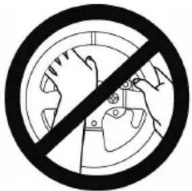
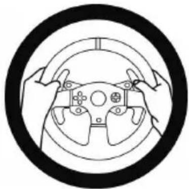
* During gameplay, always leave both hands correctly positioned on the wheel without completely letting go.
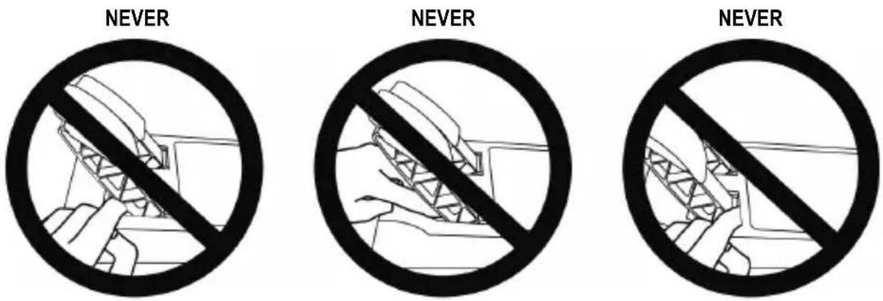
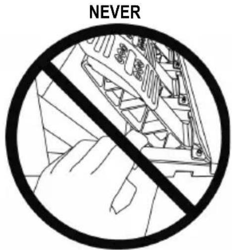
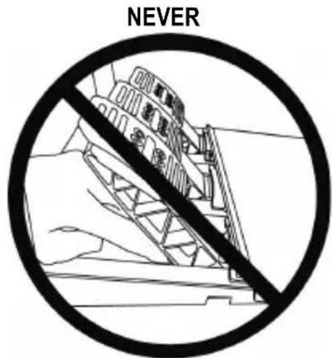
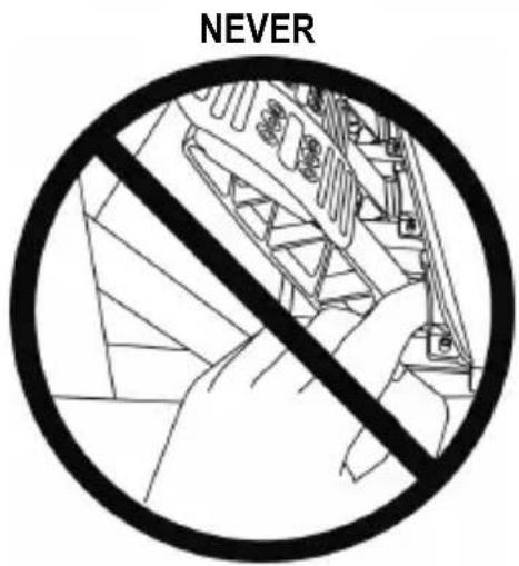
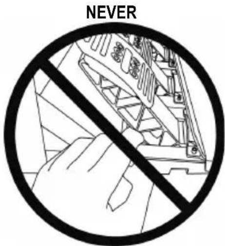
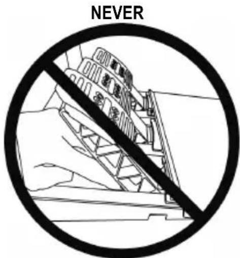
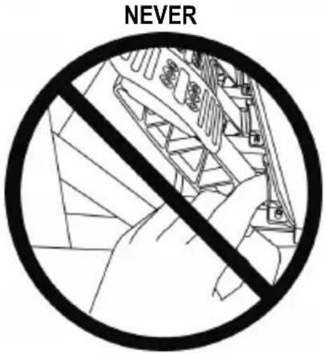
* During gameplay, never place your hands or your fingers under the pedals or anywhere near the pedal set.
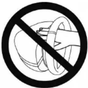
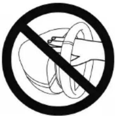
* During calibration and gameplay, never place your hand or your arm through the openings in the racing wheel.
* Make sure that the racing wheel's base is properly secured, as per this manual's instructions.
HEAVY PRODUCT

Product to be handled only by users 14 years of age or older

Be careful not to drop the product on yourself or on anyone else!
ALWAYS
natural_image
Diagram of hands holding a steering wheel with a grip, enclosed in a circular frame (no text or symbols)NEVER

NEVER

Warning – Pedal set pinch hazard when playing
* Keep the pedal set out of children's reach.
* During gameplay, never place your fingers on or anywhere near the sides of the pedals.
* During gameplay, never place your fingers on or anywhere near the pedal's rear base.
* During gameplay, never place your fingers on or anywhere near the pedal's front base.

Warning – Pedal set pinch hazard when not playing
* Store the pedal set in a safe place, and keep it out of children's reach.
UPDATING YOUR RACING WHEEL'S FIRMWARE
The firmware included in your racing wheel's base can be updated to a more recent version featuring product enhancements.
To display the firmware version that your racing wheel is currently using and update it if required: on PC, visit http://support.thrustmaster.com. Click Racing Wheels / T150 PRO Force Feedback, then select Firmware and follow the instructions describing the download and installation procedure.
Important note:
On PC, the USB sliding switch (5) on the racing wheel's base must always be set to the PS3™ position.
ADJUSTING THE PEDAL INCLINATION
The pedal inclination is adjustable.
The adjustment instructions for each pedal are available at http://support.thrustmaster.com. Click Racing Wheels / T150 PRO Force Feedback, then select Manual or FAQ.
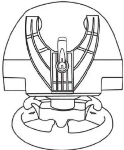
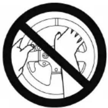
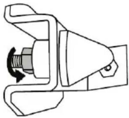
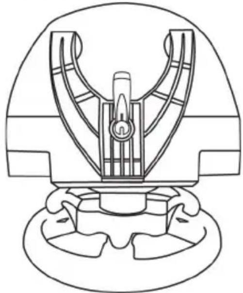
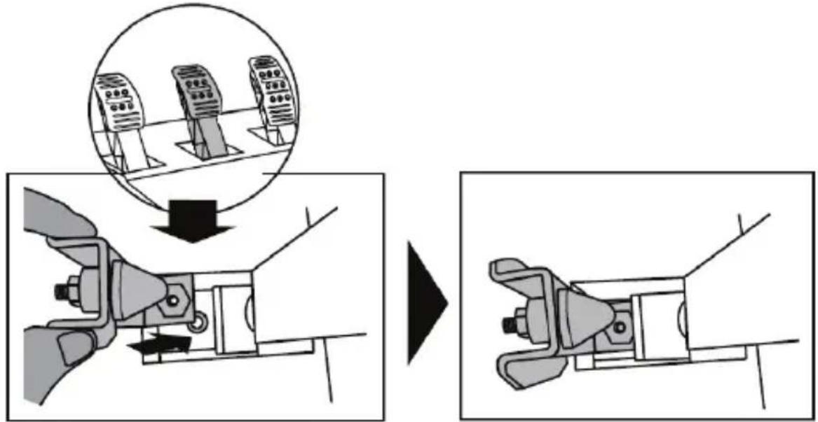
ATTACHING THE RACING WHEEL
Attaching the racing wheel to a table or a desktop
- Place the racing wheel on a table or any other horizontal, flat and stable surface.
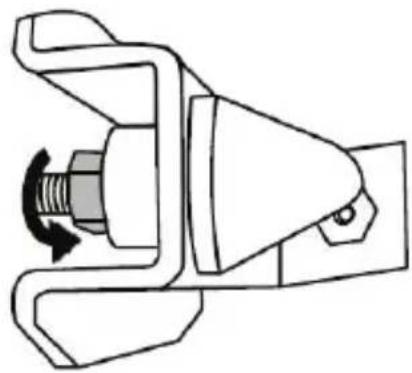
- Insert the fastening screw (11) in the attachment system (10), then tighten the device by turning the screw counterclockwise, so that it feeds into the large threaded hole (9) located beneath the racing wheel, until the wheel is perfectly stable.
ALWAYS NEVER
natural_image
Technical line drawing of a mechanical assembly with no visible text or symbols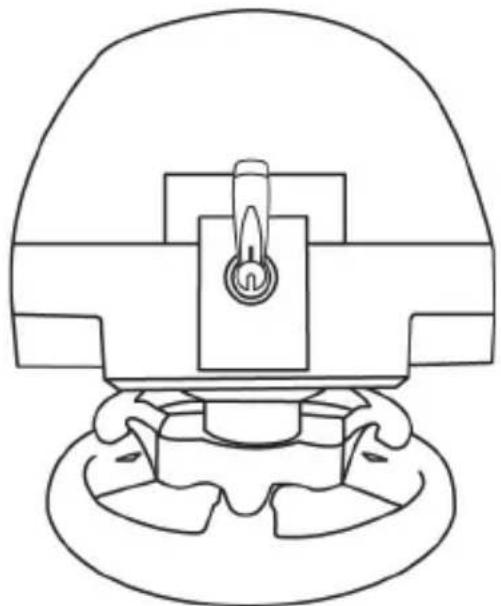
natural_image
Technical line drawing of a mechanical component with no visible text or symbolsWARNING: Never tighten the screw alone, without the attachment system in place! (This could damage the racing wheel.)
| ATTACHMENT / REMOVAL | DIRECTION |
| To tighten:Turn the screw anticlockwise | 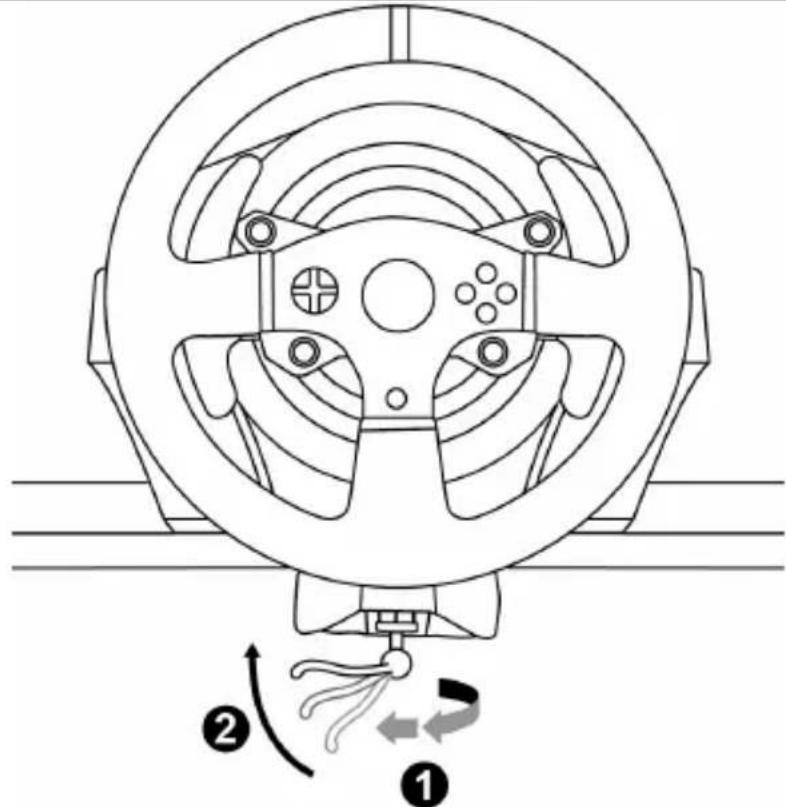 |
| To release:Turn the screw clockwise | 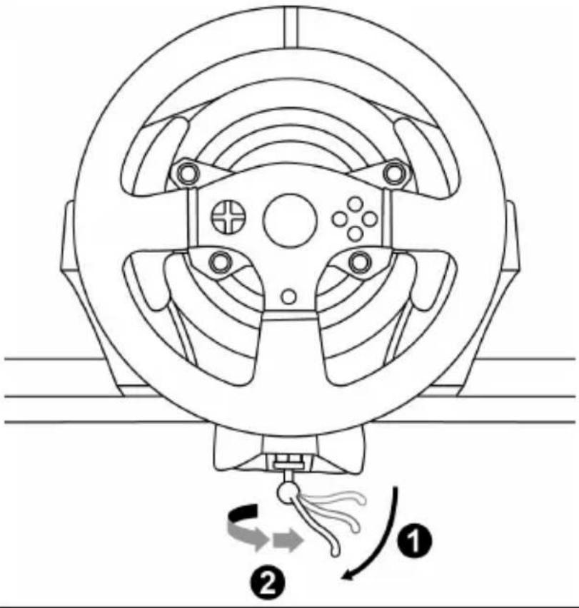 |
Attaching the pedal set to a cockpit
- Attach the pedal set using the small screw threads located on its underside.
- Drive two M6 screws (not included) through the cockpit shelf, then feed them into the two small screw threads located on the underside of the pedal set.
Important: The length of the two M6 screws must not exceed the thickness of the shelf + 10 mm; longer screws could cause damage to internal components located in the pedal set.
Layout diagrams for cockpits (for positioning the racing wheel's base and/or the pedal set) are available at http://support.thrustmaster.com: click Wheels / T150 PRO Force Feedback, then select Manual or FAQ.
PlayStation®3 and PlayStation®4 mapping
SETTING UP THE RACING WHEEL FOR PlayStation®3 OR PlayStation®4
- Connect the pedal set to the connector (17) located at the back of the racing wheel's base.
- Connect the power supply cable to the connector (14) located at the back of the racing wheel's base.
- Plug the power supply cable into an electrical outlet with the same voltage specifications.

For more information about this, please refer to the PLUGGING THE RACING WHEEL INTO AN ELECTRICAL OUTLET section, on page 3 in this manual.
- Set the USB sliding switch (5) on the racing wheel's base to either the PS3 ^TM or PS4 ^TM position, depending on the system or the game you are using.
- Connect the racing wheel's USB connector (15) to one of the system's USB ports.
- Once your system is powered on, your racing wheel will calibrate itself automatically.
- On PlayStation®4 (when the USB sliding switch is set to the PS4™ position): press the racing wheel's PS button (8) and sign in to your Sony Entertainment Network account, in order to be able to use the wheel.
You are now ready to play!
Important notes:
- The USB sliding switch (5) on the racing wheel's base must always be set to the proper position (PS3 ^TM or PS4 ^TM ) before connecting the wheel's USB cable to the system. To change the sliding switch's position, disconnect the USB cable from the system and then change the position of the switch before reconnecting the USB cable to the system.
- On PlayStation®3, the USB sliding switch (5) must always be set to the PS3™ position:
* The wheel is recognised in most games as a T500RS wheel.
* The wheel is functional in compatible games and in system menus.
* The "PS" function is functional on the wheel. - On PlayStation®4, with the USB sliding switch (5) in the PS3™ position:
* The wheel is recognised in most games as a T500RS wheel.
* The wheel is functional in compatible games, but not in system menus.
* The "SHARE" and "PS" functions are not functional on the wheel. - On PlayStation®4, with the USB sliding switch (5) in the PS4™ position:
* Don't forget to press the racing wheel's PS button (8) in order to be able to use the wheel.
* The wheel is recognised in most games as a T300 RS or T150 wheel.
* The wheel is functional in compatible games and in system menus.
* The "SHARE" and "PS" functions are functional on the wheel. - The list of PlayStation®3 and PlayStation®4 games compatible with the T150 (along with the required position for the USB sliding switch (5) according to the game being played) is available at:
http://support.thrustmaster.com (in the Racing Wheels/T150 section).
This list is updated regularly.
AUTOMATIC RACING WHEEL AND PEDAL SET CALIBRATION
The wheel automatically self-calibrates when you plug the racing wheel into an electrical outlet and connect the racing wheel's USB connector to the PlayStation ③ 3 or PlayStation ④ 4 system.
During this phase, the racing wheel will rotate quickly towards the left and the right, covering a 1080 degree angle, before stopping at the centre.

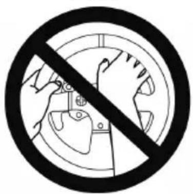
WARNING:
Never touch the racing wheel during the self-calibration phase!
(This could result in improper calibration and/or personal injuries.)
AUTOMATIC CALIBRATION OF THE PEDAL SET
Never connect the pedal set to the racing wheel's base (or disconnect it from the base) when it is connected to the system or during gameplay (this could result in improper calibration).
Always connect the pedal set before connecting the racing wheel to the system.
Once the racing wheel's calibration is complete and the game has been started, the pedals are automatically calibrated after a few presses.

WARNING:
Never press the pedals during the racing wheel's self-calibration phase or while a game is loading!
(This could result in improper calibration.)
If your racing wheel and/or pedal set do not function correctly, or if they seem to be improperly calibrated:
Power off your system and completely disconnect the racing wheel. Then reconnect all cables (including the power supply cable and the pedal set), and restart your system and your game.
MODE BUTTON AND INDICATOR LIGHT (6)
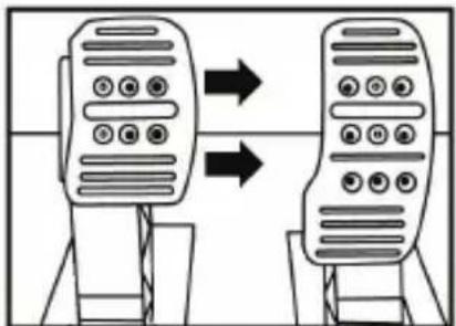
MODE button for the pedal set
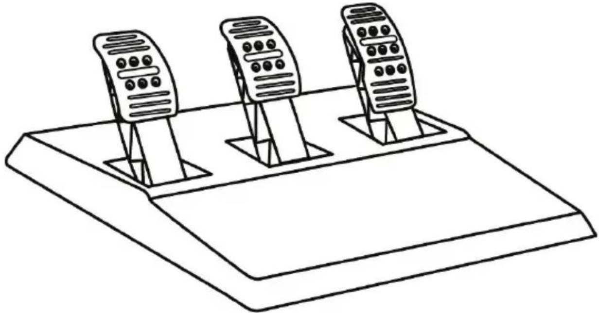
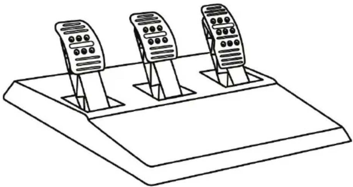
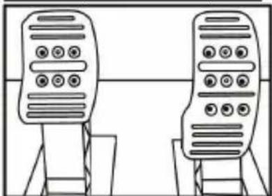
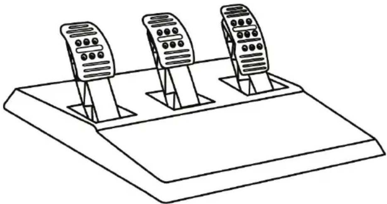
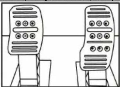
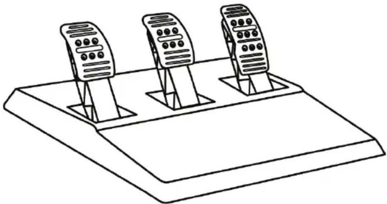
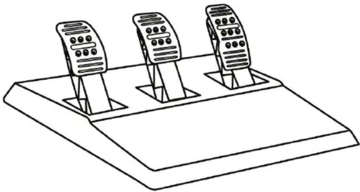
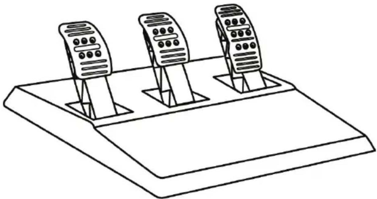
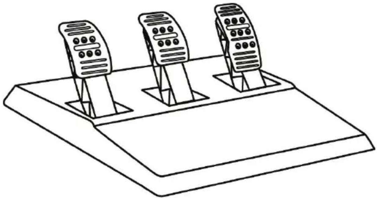
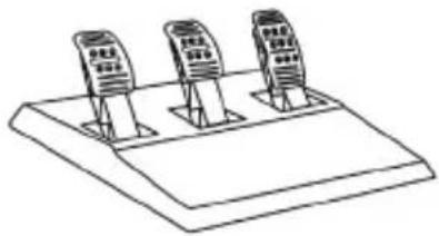
The pedal set included with the T150 features 3 pedals.
When using this pedal set, make sure that the indicator light remains red, or else the gas pedal will not function properly.
The T150 is compatible with Thrustmaster pedal sets featuring 3 pedals (sold separately); these allow you to electronically swap the accelerator and clutch pedals.
To do so, simply press the MODE button (6) for 2 seconds.
The racing wheel's internal memory stores whether the pedals have been swapped around or not.
| GAS AND CLUTCH PEDALS | Colour of the MODE indicator light (6) |
| NORMAL | RED |
| SWAPPED AROUND | GREEN |
Other information regarding the MODE button
To learn more about the MODE button and indicator light, please visit http://support.thrustmaster.com. Click Racing Wheels / T150 PRO Force Feedback, and then select Manual or FAQ.
HELP FILES AND FAQs
Please visit http://support.thrustmaster.com. Click Racing Wheels / T150 PRO Force Feedback, and then select Manual or FAQ.
SETTING UP THE RACING WHEEL FOR PC\* UPDATING YOUR RACING WHEEL'S FIRMWARE
*PC compatibility not tested nor endorsed by Sony Interactive Entertainment Europe
For more information, visit http://support.thrustmaster.com.
T3PA
THRUSTMASTER 3 PEDALS ADD-ON
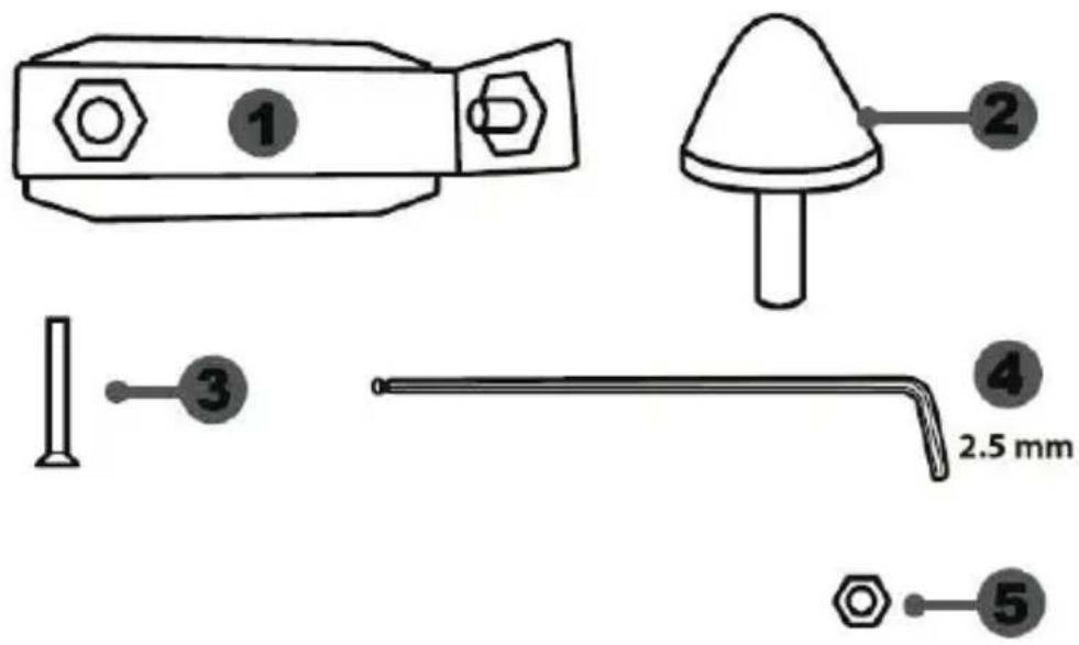
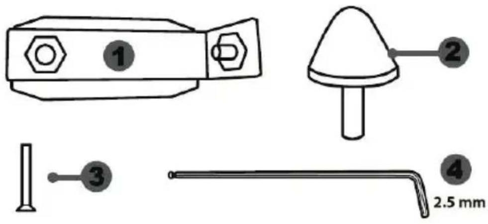
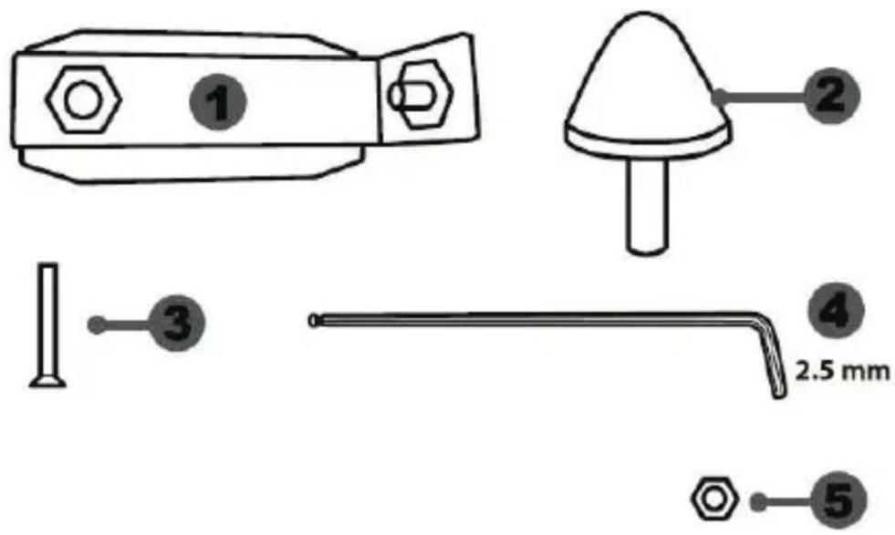
natural_image
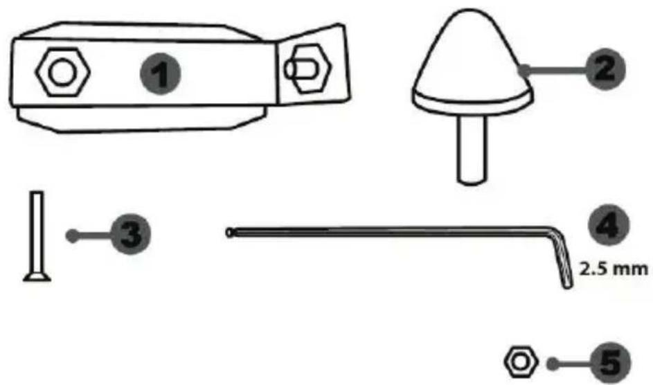
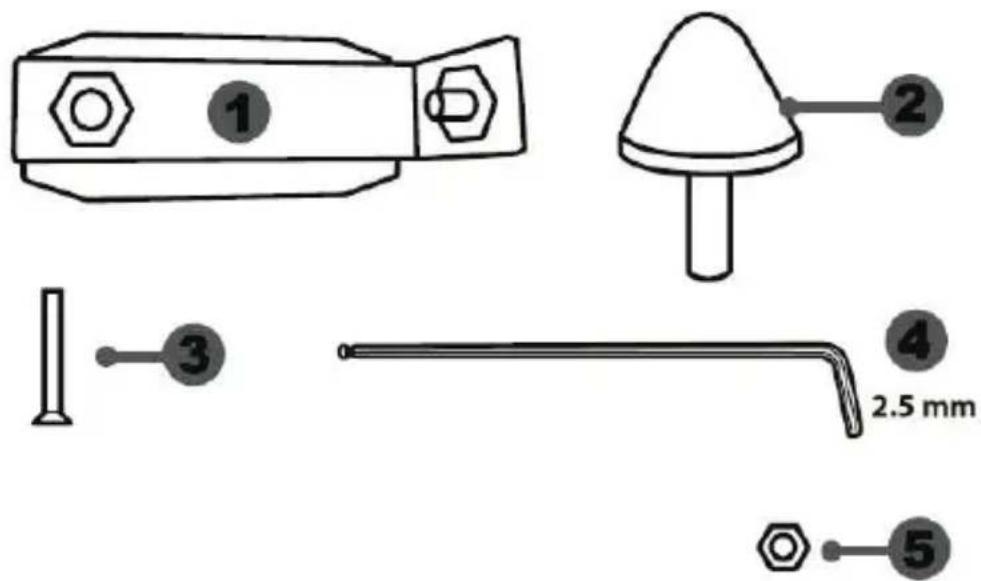
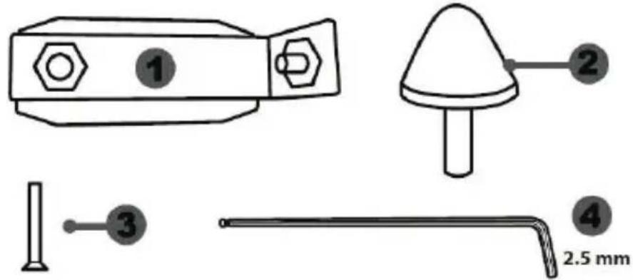
Line drawing of three identical mobile phones on a base platform (no text or symbols)TECHNICAL FEATURES
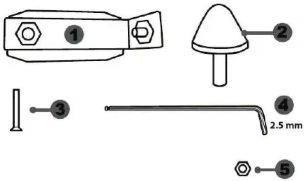
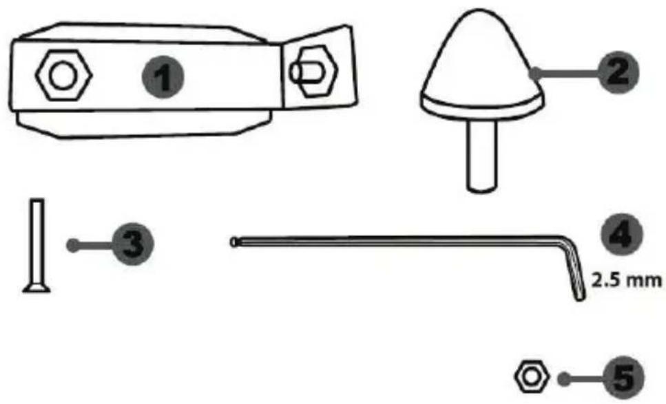
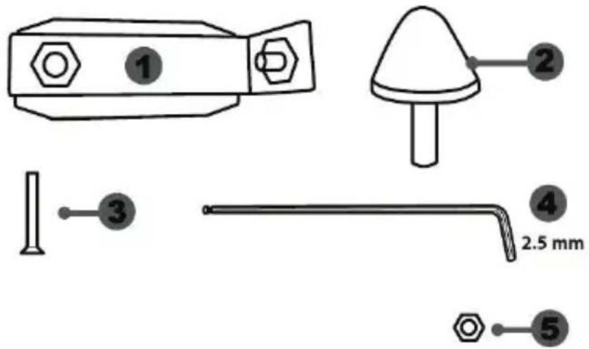
1 Metal support for conical stop (not installed by default)
2 Conical stop
3 Attachment screw for metal support
4 2.5 mm Allen key (included)
5 Position adjustment nut for conical stop
natural_image
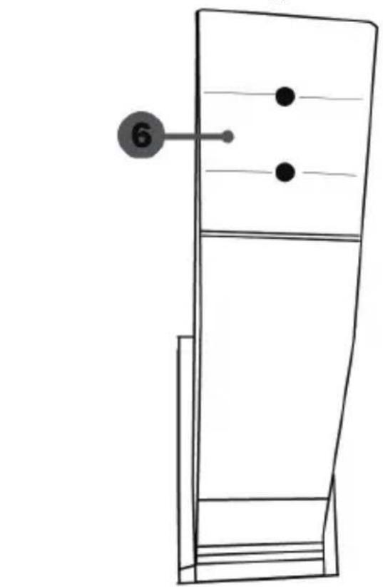
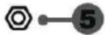
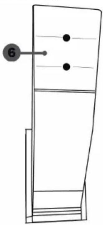
Simple line drawing of a door with two dots and a numbered label (6) pointing to the side, no text or symbols present.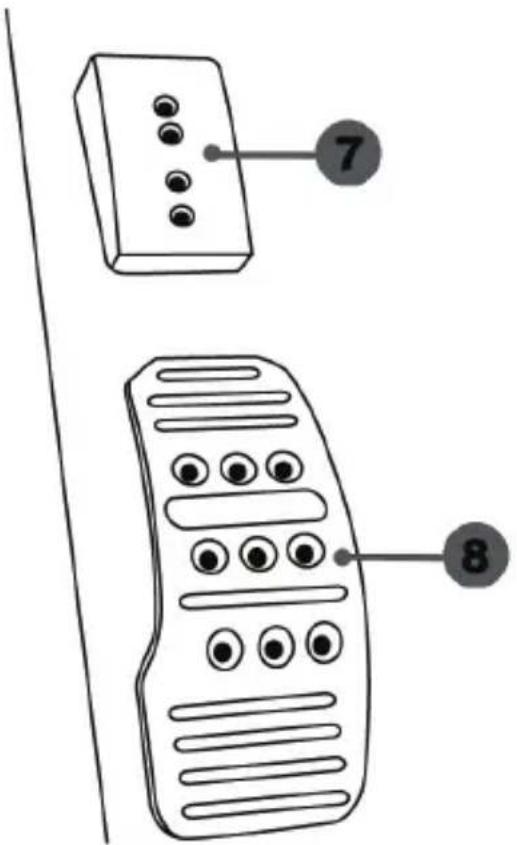
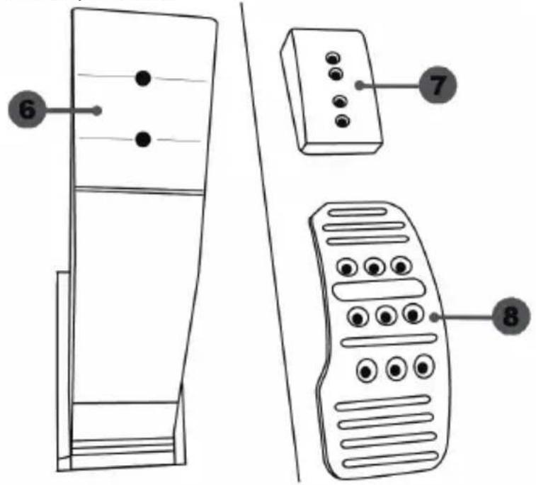
6 Pedal arm
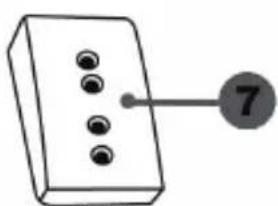
7 Plastic head support
8 Metal pedal head
WARNING
Before using this product, be sure to read these instructions carefully and save them for future reference.

For safety reasons, never use the pedal set with bare feet or while wearing only socks on your feet.
THRUSTMASTER® DISCLAIMS ALL RESPONSIBILITY IN THE EVENT OF INJURY RESULTING FROM USE OF THE PEDAL SET WITHOUT SHOES.

Warning – Pedal set pinching hazard during gaming sessions
* Keep the pedal set out of the reach of children.
* During gaming sessions, never place your fingers or thumbs on or near the sides of the pedals.
* During gaming sessions, never place your fingers or thumbs on or near the rear base of the pedals.
* During gaming sessions, never place your fingers or thumbs on or near the front base of the pedals.
AUTOMATIC CALIBRATION OF PEDALS

IMPORTANT:
- Never connect or disconnect the pedal set from the base of the wheel when the wheel is connected to the PS3 ^TM or PS4 ^TM , or during gaming sessions, to avoid calibration problems.
= Always connect the pedal set to the wheel before connecting the wheel to the PS3 ^TM or PS4 ^TM .
- Once the wheel has self-calibrated and the game has started, the pedals automatically calibrate themselves after being pressed a few times.
- Never press on the pedals when the wheel is self-calibrating or when your game is starting up, to avoid calibration problems.
- If the pedals are not functioning correctly or appear to be improperly calibrated, power off your system, completely disconnect your wheel, then reconnect all of the cables (including the power supply cable and the pedal set cable), power the system back on and restart your game.
ATTACHING THE PEDAL SET TO A COCKPIT
- Attach the pedal set using the small screw threads located on the underside of the pedal set.
- Screw two M6 screws (not included) into the cockpit's pedal support plate and into the two small screw threads located on the underside of the pedal set.
Important: The length of the two M6 screws must not exceed the thickness of the cockpit's pedal support plate plus an additional 10 mm, to avoid damaging the pedal set's internal components.
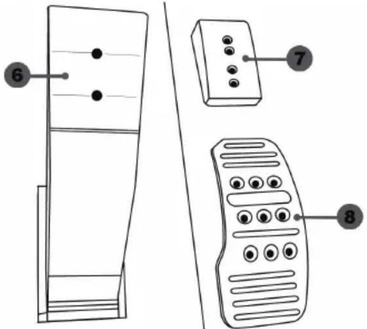
ADJUSTING THE PEDAL SET
Each of the three pedals includes:
- A metal head (8) with multiple perforations (nine for the accelerator – six for the brake – six for the clutch).
- A plastic head support (7) (placed between the head and the arm) with four perforations.
- A pedal arm (6) with two perforations.
ATTENTION: To avoid any calibration problems, be sure to always disconnect your wheel's USB cable from the PS3™ or PS4™ before making any adjustments to your pedal set.
Adjusting the HEIGHT of the accelerator pedal
- Using the included 2.5 mm Allen key (4), unscrew the two screws holding the metal head (8) and its support (7) in place.
- Select your preferred height position, then replace and re-tighten the screws so that the metal head (8) and its support (7) are held firmly in place.

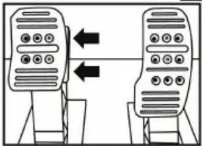
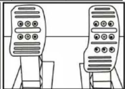
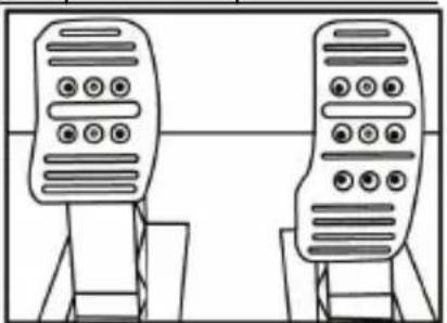
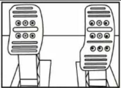
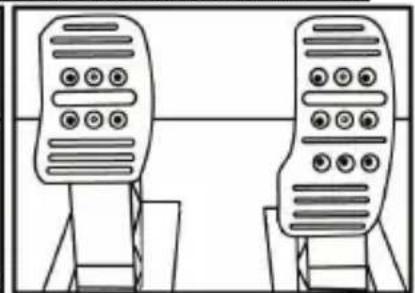
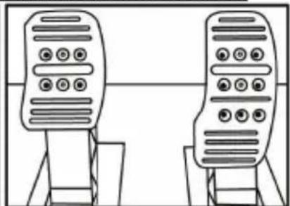
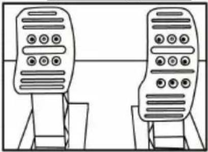
Adjusting the SPACING of the three pedals
- Using the included 2.5 mm Allen key (4), unscrew the two screws holding the metal head (8) and its support (7) in place.
- Select your preferred position (to the left, centered, or to the right), then replace and re-tighten the screws so that the metal head (8) and its support (7) are held firmly in place.
Examples illustrating the brake pedal:
natural_image
Two identical mobile phone devices connected by a bidirectional arrow, no text or symbols presentLeft position
natural_image
Line drawing of two identical mobile phones with buttons on stands (no text or symbols)Centered position (default)
flowchart
graph TD
    A["Device 1"] --> B["Device 2"]
    style A fill:#f9f,stroke:#333
    style B fill:#bbf,stroke:#333
Right position
Number of possible spacing positions per pedal:
- Three for accelerator pedal
- Three for brake pedal
- Three for clutch pedal
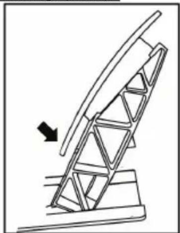
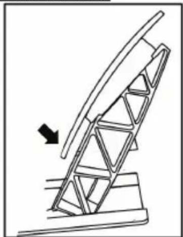
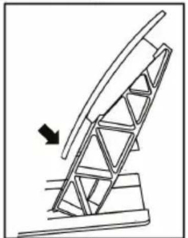
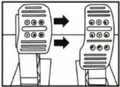
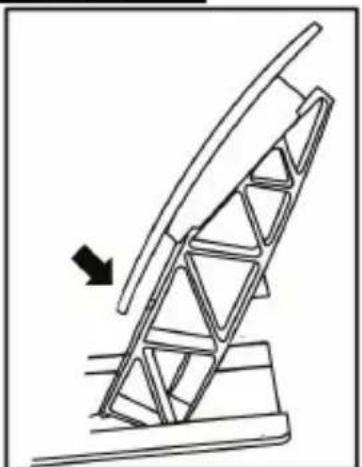
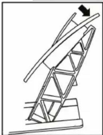
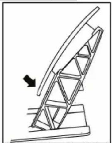
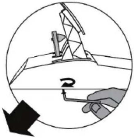
Adjusting the INCLINATION of the pedals
- Using the included 2.5 mm Allen key (4), unscrew the two screws holding the metal head (8) and its support (7) in place.
- Turn the plastic head support (7) 180°, then replace and re-tighten the screws so that the metal head (8) and its support (7) are held firmly in place.
Examples illustrating the accelerator pedal:
natural_image
Technical line drawing of a mechanical structure with a triangular frame and an arrow indicating upward motion (no text or symbols)Less inclined position
natural_image
Diagram of a mechanical structure with an arrow indicating direction, no text or symbols presentMore inclined position (default)
Number of possible inclination positions per pedal:
- Two for accelerator pedal
- Two for brake pedal
- Two for clutch pedal
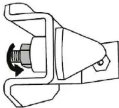
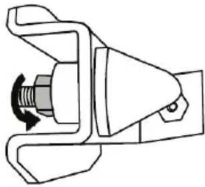
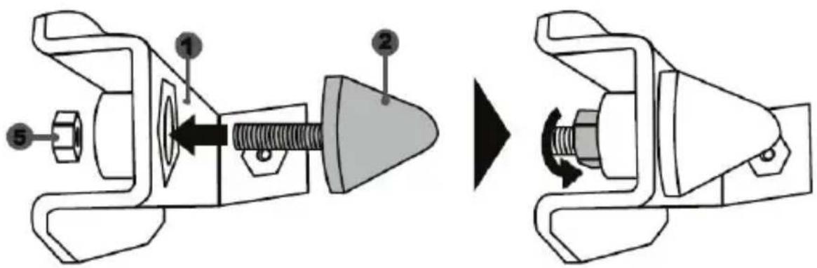
Installing the conical stop ("CONICAL RUBBER BRAKE" mod)
This modification (or "mod") is not essential, and is not installed by default. This means that the brake pedal functions perfectly even if the mod is not installed.
This mod lets you experience a different feeling and resistance when braking. It's up to you whether or not to install it, depending on your own preferences.
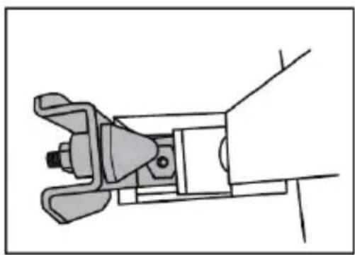
- Screw the conical stop (2) onto its metal support (1).
- Screw the position adjustment nut (5) onto the bottom (onto the conical stop's screw thread).
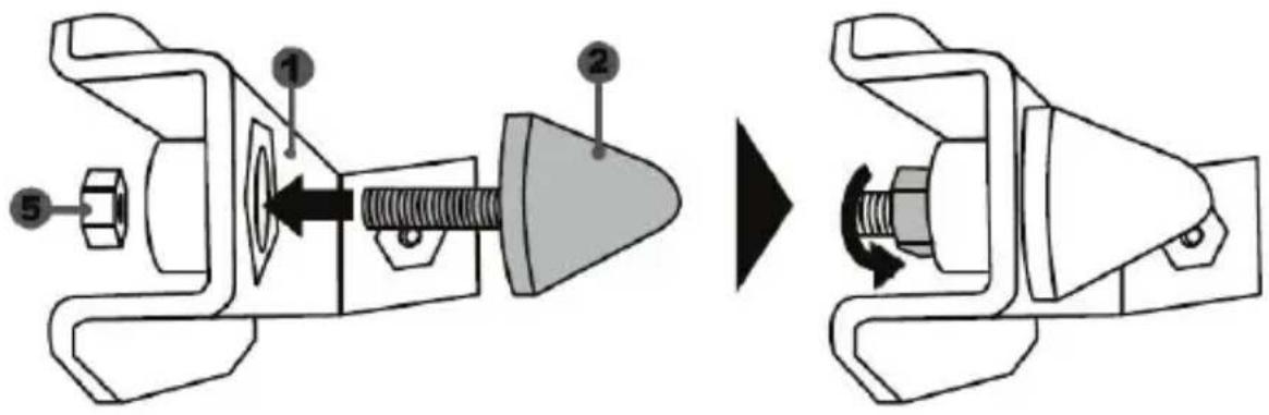
- Position the unit at the back of the brake pedal's arm.
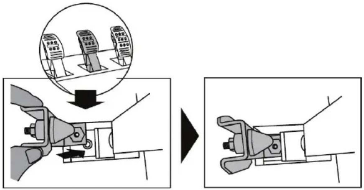
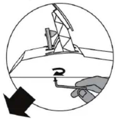
- Using the included 2.5 mm Allen key (4), attach the unit using the attachment screw (3) and the small central screw thread located on the underside of the pedal set.
natural_image
Diagram showing a hand holding a tool inside a circular frame with an oil pumpjack silhouette and a downward arrow (no text or symbols)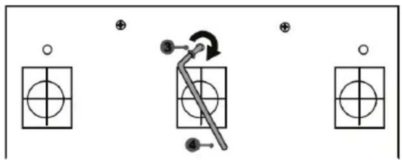
flowchart
graph TD
    A["Component 1"] --> B["Component 2"]
    B --> C["Component 3"]
    C --> D["Component 4"]
    style A fill:#f9f,stroke:#333
    style B fill:#ccf,stroke:#333
    style C fill:#cfc,stroke:#333
    style D fill:#fcc,stroke:#333
The "CONICAL RUBBER BRAKE" mod is now installed!
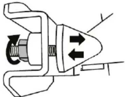
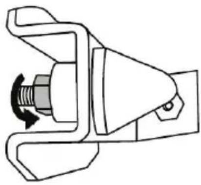
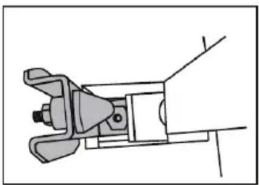
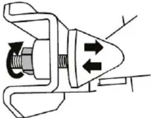
Adjusting the brake pedal's RANGE of travel and STRENGTH of resistance
By slightly unscrewing the nut (5), you can further strengthen the resistance of the brake pedal by moving the conical stop (2) closer to the back of the pedal's arm (if necessary, use a 14 ~mm wrench or pliers to re-tighten the nut and maintain the selected position). The closer the conical stop is positioned to the back of the pedal's arm, the greater the strength of resistance will be.
natural_image
Mechanical component diagram showing a valve mechanism with directional arrows (no text or symbols)Note: When the conical stop is very close to the back of the brake pedal's arm, you may experience difficulties in reaching the maximum calibration value. Should that be the case:
* Slowly, press very hard on the brake pedal so as to reach the maximum value (if necessary, stand very briefly on the pedal – just for a second), then release the pressure; or else
* Move the conical stop a bit farther away from the back of the brake pedal's arm.
CONSUMER WARRANTY INFORMATION
Worldwide, Guillemot Corporation S.A., whose registered office is located at Place du Granier, B.P. 97143, 35571 Chantepie, France (hereinafter "Guillemot") warrants to the consumer that this Thrustmaster product shall be free from defects in materials and workmanship, for a warranty period which corresponds to the time limit to bring an action for conformity with respect to this product. In the countries of the European Union, this corresponds to a period of two (2) years from delivery of the Thrustmaster product. In other countries, the warranty period corresponds to the time limit to bring an action for conformity with respect to the Thrustmaster product according to applicable laws of the country in which the consumer was domiciled on the date of purchase of the Thrustmaster product (if no such action exists in the corresponding country, then the warranty period shall be one (1) year from the original date of purchase of the Thrustmaster product).
Should the product appear to be defective during the warranty period, immediately contact Technical Support, who will indicate the procedure to follow. If the defect is confirmed, the product must be returned to its place of purchase (or any other location indicated by Technical Support). Within the context of this warranty, the consumer's defective product shall, at Technical Support's option, be either replaced or returned to working order. If, during the warranty period, the Thrustmaster product is subject to such reconditioning, any period of at least seven (7) days during which the product is out of use shall be added to the remaining warranty period (this period runs from the date of the consumer's request for intervention or from the date on which the product in question is made available for reconditioning, if the date on which the product is made available for reconditioning is subsequent to the date of the request for intervention). If permitted under applicable law, the full liability of Guillemot and its subsidiaries (including for consequential damages) is limited to the return to working order or the replacement of the Thrustmaster product. If permitted under applicable law, Guillemot disclaims all warranties of merchantability or fitness for a particular purpose.
This warranty shall not apply: (1) if the product has been modified, opened, altered, or has suffered damage as a result of inappropriate or abusive use, negligence, an accident, normal wear, or any other cause unrelated to a material or manufacturing defect (including, but not limited to, combining the Thrustmaster product with any unsuitable element, including in particular power supplies, rechargeable batteries, chargers, or any other elements not supplied by Guillemot for this product); (2) if the product has been used for any use other than home use, including for professional or commercial purposes (game rooms, training, competitions, for example); (3) in the event of failure to comply with the instructions provided by Technical Support; (4) to software, said software being subject to a specific warranty; (5) to consumables (elements to be replaced over the product's lifespan: disposable batteries, audio headset or headphone ear pads, for example); (6) to accessories (cables, cases, pouches, bags, wrist-straps, for example); (7) if the product was sold at public auction.
This warranty is nontransferable.
The consumer's legal rights with respect to laws applicable to the sale of consumer goods in his or her country are not affected by this warranty.
Additional warranty provisions
During the warranty period, Guillemot shall not provide, in principle, any spare parts, as Technical Support is the only party authorized to open and/or recondition any Thrustmaster product (with the exception of any reconditioning procedures which Technical Support may request that the consumer carry out, by way of written instructions – for example, due to the simplicity and the lack of confidentiality of the reconditioning process – and by providing the consumer with the required spare part(s), where applicable).
Given its innovation cycles and in order to protect its know-how and trade secrets, Guillemot shall not provide, in principle, any reconditioning notification or spare parts for any Thrustmaster product whose warranty period has expired.
Liability
If permitted under applicable law, Guillemot Corporation S.A. (hereinafter “Guillemot”) and its subsidiaries disclaim all liability for any damages caused by one or more of the following: (1) the product has been modified, opened or altered; (2) failure to comply with assembly instructions; (3) inappropriate or abusive use, negligence, an accident (an impact, for example); (4) normal wear; (5) the use of the product for any use other than home use, including for professional or commercial purposes (game rooms, training, competitions, for example). If permitted under applicable law, Guillemot and its subsidiaries disclaim all liability for any damages unrelated to a material or manufacturing defect with respect to the product (including, but not limited to, any damages caused directly or indirectly by any software, or by combining the Thrustmaster product with any unsuitable element, including in particular power supplies, rechargeable batteries, chargers, or any other elements not supplied by Guillemot for this product).

COPYRIGHT
© 2017 Guillemot Corporation S.A. All rights reserved. Thrustmaster ^® is a registered trademark of Guillemot Corporation S.A.
Licensed for sale in Europe, Africa, Middle East, Russia, India and Oceania. For use exclusively with PlayStation®3 and PlayStation®4.
All other trademarks and brand names are hereby acknowledged and are property of their respective owners. Illustrations not binding. Contents, designs and specifications are subject to change without notice and may vary from one country to another. Made in China.
Manufactured and distributed by Guillemot Corporation S.A.
ENVIRONMENTAL PROTECTION RECOMMENDATION
natural_image
Simple line drawing of a trash bin with no text or symbolsIn the European Union and Turkey: At the end of its working life, this product should not be disposed of with standard household waste, but rather dropped off at a collection point for the disposal of Waste Electrical and Electronic Equipment (WEEE) for recycling.
This is confirmed by the symbol found on the product, user manual or packaging. Depending on their characteristics, the materials may be recycled. Through recycling and other forms of processing Waste Electrical and Electronic Equipment, you can make a significant contribution towards helping to protect
the environment.
Please contact your local authorities for information on the collection point nearest you.
For all other countries: Please adhere to local recycling laws for electrical and electronic equipment.
Retain this information. Colours and decorations may vary.
Plastic fasteners and adhesives should be removed from the product before it is used.
www.thrustmaster.com
*Applicable to EU and Turkey only


T150 PRO
FORCE FEEDBACK
natural_image
Line drawing of a steering wheel and three motor drive stations (no text or symbols)ATTENTION :
natural_image
Technical line drawing of a mechanical assembly with no visible text or symbols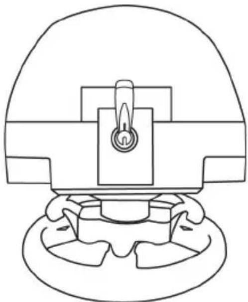
natural_image
Technical line drawing of a mechanical component with a central knob and base (no text or symbols)THRUSTMASTER 3 PEDALS ADD-ON
natural_image
Line drawing of three identical speed limit switches mounted on a base platform (no text or symbols)CARACTERISTIQUES TECHNIQUES

natural_image
Simple line drawing of a door with two dots and a numbered label (6) pointing to the side, no text or symbols present.natural_image
Simple 3D diagram of a rectangular block with four circular holes and a numbered circle (7) pointing to its top edge (no text or symbols beyond the number)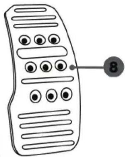
natural_image
Two identical mobile phone devices with left-hand side indicators and bidirectional arrows (no text or symbols)Position à gauche
natural_image
Line drawing of two identical mobile phone controllers standing upright (no text or symbols)natural_image
Diagram of a ladder structure with an arrow indicating upward motion (no text or symbols present)natural_image
Diagram of a mechanical structure with an arrow indicating direction, no text or symbols present
natural_image
Technical line drawing of a mechanical clamp or lever mechanism (no text or symbols)natural_image
Illustration of an oil pumpjack inside a circular frame with a hand holding a tool, no text or symbols present.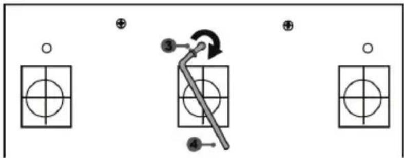
flowchart
graph TD
    A["Input Grid"] --> B["Step ③"]
    B --> C["Step ④"]
    C --> D["Output Grid"]
    style A fill:#f9f,stroke:#333
    style B fill:#ccf,stroke:#333
    style C fill:#cfc,stroke:#333
    style D fill:#fcc,stroke:#333
natural_image
Mechanical component diagram showing a valve mechanism with directional arrows (no text or symbols)INFORMATIONS RELATIVES A LA GARANTIE AUX CONSOMMATEURS
natural_image
Three black icons: a lowercase 'i' in a circle, an envelope symbol, and a telephone handset (no text or labels)COPYRIGHT
natural_image
Symbol of a trash bin with crossed lines indicating no waste or restriction, plus a solid black rectangle below (no text or symbols)www.thrustmaster.com
natural_image
Line drawing of a steering wheel and three motor drive holders on a platform (no text or symbols)ACHTUNG!
natural_image
Diagram of hands holding a steering wheel inside a circular frame (no text or symbols)NIE
NIE


natural_image
Technical line drawing of a mechanical instrument or dial assembly (no text or symbols)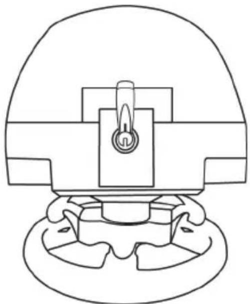
natural_image
Technical line drawing of a mechanical component with no visible text or symbolsTHRUSTMASTER 3 PEDALS ADD-ON
natural_image
Line drawing of three identical speed limit switches mounted on a base platform (no text or symbols)TECHNISCHE MERKMALE
EINBAU DES PEDALSETS IN EIN COCKPIT
ANPASSEN DES PEDALSETS
natural_image
Two identical mobile phones with circular buttons on top, connected by a black arrow indicating sound or signal (no text or symbols present)natural_image
Two identical mobile phone controllers with circular buttons on top, connected by a black arrow (no text or symbols)Hohe Position
natural_image
Two identical mobile phone controllers with left-hand side indicators (no text or symbols)Linke Position
natural_image
Two identical mobile phone controllers standing upright, no text or symbols visiblenatural_image
Diagram of a ladder structure with an arrow indicating upward motion (no text or symbols)natural_image
Diagram of a ladder-like structure with an arrow indicating upward motion (no text or symbols present)natural_image
Diagram showing a hand holding a tool near an oil pumpjack, with a black arrow indicating direction (no text or symbols)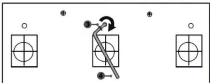
natural_image
Mechanical assembly diagram showing a valve mechanism with directional arrows (no text or labels)COPYRIGHT
natural_image
Symbol of a trash bin with crossed lines indicating no waste or discharge (no text or labels)www.thrustmaster.com
natural_image
Technical line drawing of a mechanical component with no visible text or symbols
natural_image
Line drawing of three identical mobile phone modules mounted on a base (no text or symbols)WAARSCHUWING:
natural_image
Diagram of hands holding a steering wheel with a handheld device, enclosed in a circular frame (no text or symbols)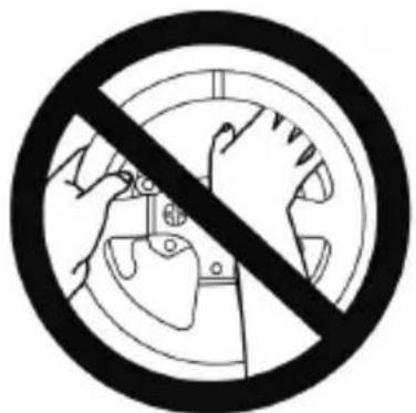


natural_image
Technical line drawing of a mechanical assembly with no visible text or symbols
natural_image
Technical line drawing of a mechanical component with no visible text or symbolsTHRUSTMASTER 3 PEDALS ADD-ON
natural_image
Line drawing of three identical mobile phones on a base platform (no text or symbols)6 Pedaalarm
7 Kunststof pedaalsteun
8 Metalen pedaal
WAARSCHUWING
DE PEDAALSET AAN EEN COCKPIT BEVESTIGEN
natural_image
Two identical mobile phone controllers on stands, one with a downward arrow indicating change (no text or symbols present)natural_image
Two identical mobile phone controllers on stands, one with a black upward arrow indicating connection (no text or symbols present)Hoge stand
natural_image
Two identical mobile phone controllers with left-hand side arrows, no text or symbols presentLinks
natural_image
Line drawing of two identical mobile phone devices standing upright, no text or symbols presentnatural_image
Diagram of a mechanical structure with triangular supports and a directional arrow (no text or symbols)Kleine hoek
natural_image
Line drawing of a mechanical structure with an arrow indicating direction (no text or symbols)natural_image
Diagram showing a hand holding a tool near an oil pumpjack, with a circular arrow indicating rotation (no text or symbols)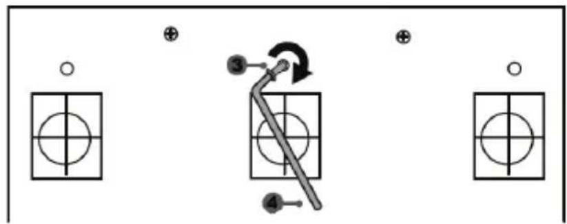
flowchart
graph TD
    A["○"] --> B["○"]
    C["⊕"] --> D["○"]
    E["●"] --> F["○"]
    G["●"] --> H["○"]
    I["③"] --> J["←"]
    K["④"] --> L["←"]
    style A fill:#fff,stroke:#000
    style C fill:#fff,stroke:#000
    style E fill:#fff,stroke:#000
    style G fill:#fff,stroke:#000
    style I fill:#fff,stroke:#000
    style J fill:#fff,stroke:#000
    style K fill:#fff,stroke:#000
De "CONICAL RUBBER BRAKE" mod is nu gemonteerd
natural_image
Mechanical component diagram showing a valve mechanism with directional arrows (no text or symbols)natural_image
Symbol of a trash bin crossed with diagonal lines, no text or labels presentwww.thrustmaster.com
natural_image
Technical line drawing of a mechanical component with no visible text or symbols
natural_image
Line drawing of three identical mobile phone modules on a base platform (no text or symbols)ATTENZIONE:
natural_image
Diagram of hands holding a steering wheel, enclosed in a circular frame (no text or symbols)MAI
MAI


natural_image
Technical line drawing of a mechanical assembly with no visible text or symbols
natural_image
Technical line drawing of a mechanical component with no visible text or symbolsTHRUSTMASTER 3 PEDALS ADD-ON

natural_image
Line drawing of three identical mobile phones on a base platform (no text or symbols)CARATTERISTICHE TECNICHE
natural_image
Two identical mobile phone controllers with buttons on top, connected by a black arrow indicating a change (no text or symbols present)natural_image
Two identical mobile phones with circular buttons on stands, connected by a horizontal line and an upward arrow (no text or symbols)Posizione alta
natural_image
Two identical mobile phone devices connected by a bidirectional arrow, no text or symbols presentnatural_image
Line drawing of two identical mobile phones with buttons on stands (no text or symbols)natural_image
Diagram of a mechanical structure with a ladder and support beams, no text or symbols presentnatural_image
Diagram of a mechanical structure with an arrow indicating direction, no text or symbols present

natural_image
Mechanical component diagram showing a valve mechanism with a rotating knob (no text or symbols)natural_image
Illustration of an oil pumpjack inside a circle with a hand holding a tool, no text or symbols present.
natural_image
Mechanical component diagram showing a valve mechanism with directional arrows (no text or labels)COPYRIGHT
natural_image
Symbol of a trash bin crossed with no text or labels, accompanied by a black rectangular block below (no text or symbols present)www.thrustmaster.com
natural_image
Line drawing of a steering wheel and three motor drive holders on a platform (no text or symbols)ADVERTENCIA:
natural_image
Diagram of hands holding a steering wheel, enclosed in a circular frame (no text or symbols)NUNCA
NUNCA

natural_image
Technical line drawing of a mechanical instrument or dial (no text or symbols present)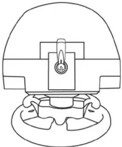
natural_image
Line drawing of a mechanical component with a central knob and base (no text or symbols)THRUSTMASTER 3 PEDALS ADD-ON

natural_image
Line drawing of three identical mobile phones on a base platform (no text or symbols)CARACTERÍSTICAS TÉCNICAS
natural_image
Simple line drawing of a door with two dots and a numbered label (6) pointing to the side, no text or symbols present.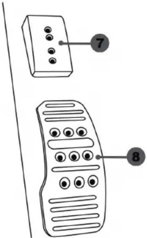
natural_image
Diagram showing two identical mobile phones with circular buttons on their heads, connected by a downward arrow (no text or symbols)natural_image
Two identical mobile phone screens with buttons and a bidirectional arrow between them (no text or symbols)Posición alta
natural_image
Two identical mobile phone controllers with left-hand side arrows, no text or symbols presentPosición izquierda
natural_image
Line drawing of two identical mobile phones on stands, no text or symbols presentnatural_image
Diagram of a mechanical structure with a triangular frame and an arrow indicating upward motion (no text or symbols)natural_image
Diagram of a mechanical structure with an arrow indicating direction, no text or symbols present
natural_image
Mechanical component diagram showing a valve mechanism with a rotating knob (no text or symbols)natural_image
Illustration of an oil pumpjack inside a circular frame with a hand holding a tool, no text or symbols present.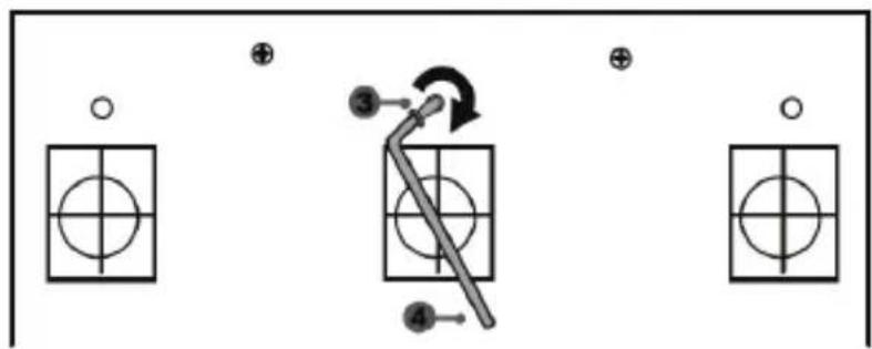
flowchart
graph TD
    A["Step 1: Circle with crosshairs"] --> B["Step 2: Arrow pointing to a lever"]
    B --> C["Step 3: Arrow with arrow indicating rotation"]
    C --> D["Step 4: Arrow pointing to a shaft"]
    D --> E["End"]
natural_image
Mechanical assembly diagram showing a valve mechanism with directional arrows (no text or labels)natural_image
Symbol of a trash bin crossed with diagonal lines, no text or labels presentwww.thrustmaster.com
natural_image
Line drawing of a steering wheel and three handheld motors on a platform (no text or symbols)ATENÇÃO:
natural_image
Diagram of hands holding a steering wheel, enclosed in a circular frame (no text or symbols)NUNCA

NUNCA


natural_image
Technical line drawing of a mechanical assembly with no visible text or symbols
natural_image
Technical line drawing of a mechanical component with no visible text or symbolsTHRUSTMASTER 3 PEDALS ADD-ON
natural_image
Line drawing of three identical mobile phones on a base platform (no text or symbols)CARACTERÍSTICAS TÉCNICAS

CALIBRAGEM AUTOMÁTICA DOS PEDAIS

IMPORTANTE:
- Nunca ligue nem desligue o conjunto de pedais da base do volante quando este estiver ligado à PS3™ ou à PS4™, ou durante as sessões de jogo, para evitar problemas de calibragem.
= Ligue sempre o conjunto de pedais ao volante antes de ligar o volante à PS3 ^TM ou à PS4 ^TM .
FIXAR O CONJUNTO DE PEDAIS A UM COCKPIT
- Fixe o conjunto de pedais utilizando as pequenas roscas de parafusos situadas na parte inferior do conjunto de pedais.
- Enrosque dois parafusos M6 (não incluídos) na chapa de apoio do conjunto de pedais e nas duas pequenas roscas de parafusos situadas na parte inferior do conjunto de pedais.
natural_image
Two identical mobile phones with circular buttons on stands, connected by a black arrow indicating sound or signal change (no text or symbols present)natural_image
Two identical mobile phone screens with circular buttons on stands, connected by a black arrow (no text or symbols)Posição alta
natural_image
Two identical mobile phone controllers with left-hand side indicators (no text or symbols)Posição à esquerda
natural_image
Line drawing of two identical mobile phones with buttons on stands (no text or symbols)natural_image
Diagram of a ladder structure with an arrow indicating upward motion (no text or symbols)natural_image
Diagram of a mechanical structure with an arrow indicating direction, no text or symbols presentnatural_image
Illustration of a hand using a tool to measure a circular component with an arrow, no text or symbols present.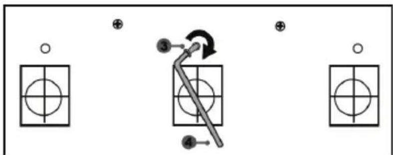
flowchart
graph TD
    A["Input"] --> B["Step 3"]
    B --> C["Step 4"]
    C --> D["Output"]
    style A fill:#fff,stroke:#000
    style B fill:#fff,stroke:#000
    style C fill:#fff,stroke:#000
    style D fill:#fff,stroke:#000
natural_image
Mechanical assembly diagram showing a valve mechanism with directional arrows (no text or labels)natural_image
Symbol of a trash bin crossed with a cross, no text or labels presentwww.thrustmaster.com
natural_image
Line drawing of a steering wheel and three motor drive holders on a platform (no text or symbols)ВНИМАНИЕ!
natural_image
Illustration of hands holding a steering wheel inside a circular frame (no text or symbols)НЕЛЬЗЯ

НЕЛЬЗЯ

natural_image
Technical line drawing of a mechanical instrument or dial (no text or symbols present)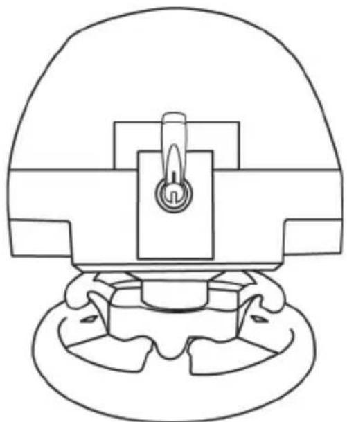
natural_image
Technical line drawing of a mechanical component with a central knob and base mount (no text or symbols)THRUSTMASTER 3 PEDALS ADD-ON

natural_image
Line drawing of three identical mobile phones on a base platform (no text or symbols)natural_image
Two identical mobile phone controllers with buttons and a downward arrow indicating interaction (no text or symbols)natural_image
Two identical mobile phone icons on stands, one with a black upward arrow between them (no text or symbols)Высокое положение
natural_image
Line drawing of two identical mobile phones with buttons on stands (no text or symbols)natural_image
Diagram of a mechanical structure with triangular supports and a directional arrow (no text or symbols)Угол наклона меньше
natural_image
Diagram of a mechanical structure with an arrow indicating direction, no text or symbols presentnatural_image
Illustration of an oil pumpjack inside a circular frame, with a hand holding a tool and a downward arrow indicating rotation (no text or symbols)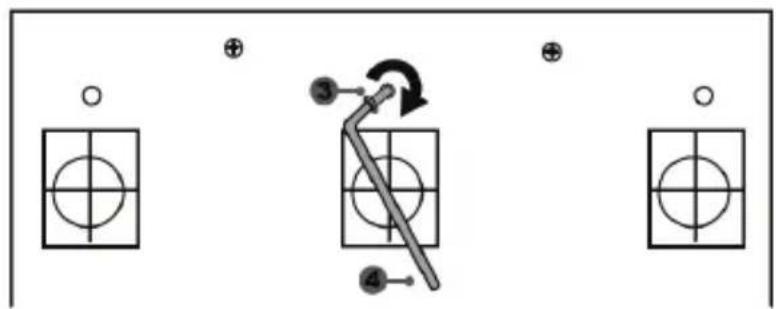
flowchart
graph TD
    A["○"] --> B["○"]
    C["⊕"] --> D["○"]
    E["●"] --> F["○"]
    G["⊕"] --> H["○"]
    I["●"] --> J["○"]
    K["●"] --> L["○"]
    M["●"] --> N["○"]
    O["●"] --> P["○"]
    Q["●"] --> R["○"]
    S["●"] --> T["○"]
    U["●"] --> V["○"]
    W["●"] --> X["○"]
    Y["●"] --> Z["○"]
Модуль CONICAL RUBBER BRAKE mod установлен!
natural_image
Mechanical component diagram showing a valve mechanism with directional arrows (no text or labels)www.thrustmaster.com
EAC

T150 PRO
FORCE FEEDBACK
Εγχειρίδιο χρήσης
natural_image
Line drawing of a steering wheel and three motor control switches on a platform (no text or symbols)ΠΡΟΕΙΔΟΠΟΙΗΣΗ:
natural_image
Diagram of hands holding a steering wheel with no text or symbolsПОТЕ

ПОТЕ


natural_image
Technical line drawing of a mechanical assembly with no visible text or symbols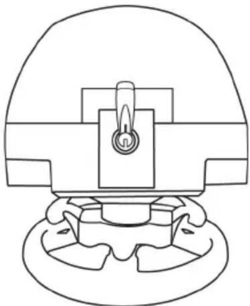
natural_image
Technical line drawing of a mechanical component with a central knob and base mount (no text or symbols)T3PA THRUSTMASTER 3 PEDALS ADD-ON

natural_image
Line drawing of three identical mobile phones on a base platform (no text or symbols)TEXNIKA XAPAKTHPIΣTIKA
natural_image
Diagram showing two identical mobile devices connected by a double-headed arrow, with no text or symbols present.natural_image
Two identical mobile phone screens with buttons and a bidirectional arrow between them (no text or symbols)Υψηλή θέση

natural_image
Mechanical component diagram showing a valve mechanism with a rotating knob (no text or symbols)natural_image
Diagram showing a hand holding a tool inside a circular frame with an oil pumpjack, and a downward arrow indicating rotation (no text or symbols)
natural_image
Mechanical component diagram showing a valve or connector with directional arrows indicating flow or movement (no text or symbols present)natural_image
Simple line drawing of a trash bin with crossed lines and a black rectangular base (no text or symbols)www.thrustmaster.com
natural_image
Technical line drawing of a steering wheel assembly (no text or symbols)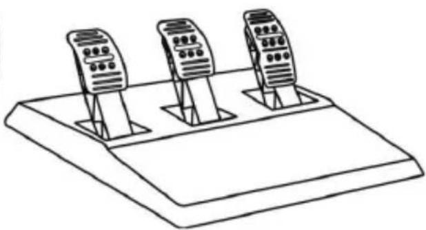
natural_image
Line drawing of three identical mobile phone modules mounted on a base (no text or symbols)UYARI:
natural_image
Diagram of hands holding a steering wheel with game controller (no text or symbols)ASLA

ASLA

natural_image
Technical line drawing of a mechanical instrument or dial (no text or symbols present)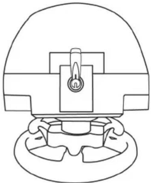
natural_image
Technical line drawing of a mechanical component with no visible text or symbolsTHRUSTMASTER 3 PEDALS ADD-ON
natural_image
Line drawing of three mobile phones on a base platform (no text or symbols)TEKNİK ÖZELLİKLER
natural_image
Two identical mobile phones with circular buttons on top, connected by a black arrow indicating rotation (no text or symbols)natural_image
Two identical mobile phone screens with circular buttons on stands, connected by a black arrow (no text or symbols)Yüksek pozisyon
natural_image
Two identical mobile phone devices with left-pointing arrows indicating bidirectional connection (no text or symbols)Sol pozisyon
natural_image
Two identical mobile phone controllers standing upright, no text or symbols visiblenatural_image
Technical line drawing of a mechanical structure with an arrow indicating upward motion (no text or symbols)Az eğimli pozisyon
natural_image
Line drawing of a mechanical ladder with an arrow indicating motion direction (no text or symbols)
natural_image
Mechanical component diagram showing a valve or connector with a rotating knob (no text or symbols)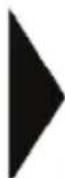
natural_image
Technical line drawing of a mechanical clamp or bracket assembly (no text or symbols)natural_image
Diagram showing a hand holding a tool inside a circular frame, with an arrow indicating rotation or direction (no text or symbols present)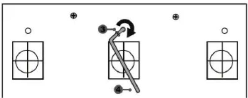
"CONICAL RUBBER BRAKE" mod şimdi monteli!
natural_image
Mechanical assembly diagram showing a valve mechanism with directional arrows (no text or labels)TELİF HAKKI
www.thrustmaster.com
natural_image
Line drawing of a steering wheel and three handheld motors on a platform (no text or symbols)OSTRZEŻENIE:
natural_image
Diagram of hands holding a steering wheel, enclosed in a circular frame (no text or symbols)NIGDY
NIGDY


natural_image
Technical line drawing of a mechanical assembly with no visible text or symbols
natural_image
Technical line drawing of a mechanical component with no visible text or symbolsTHRUSTMASTER 3 PEDALS ADD-ON
natural_image
Line drawing of three identical mobile phones on a base platform (no text or symbols)ELEMENTY
natural_image
Diagram showing two identical devices connected by a double-headed arrow, indicating a change or transformation (no text or symbols present)natural_image
Two identical mobile phone icons on stands, one with a black upward arrow between them (no text or symbols)Położenie wysokie
natural_image
Two identical mobile phone controllers with left-hand side arrows, no text or symbols presentPołożenie lewe
natural_image
Line drawing of two identical mobile phones with control buttons and display screens (no text or symbols)natural_image
Diagram of a mechanical structure with triangular supports and a directional arrow (no text or symbols)Mniejsze nachylenie
natural_image
Diagram of a mechanical structure with an arrow indicating direction, no text or symbols present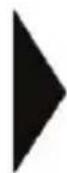
natural_image
Mechanical component diagram showing a valve or actuator assembly with a rotating knob (no text or symbols)natural_image
Illustration of an oil pump with a hand holding a tool, showing a circular frame and a downward arrow (no text or symbols)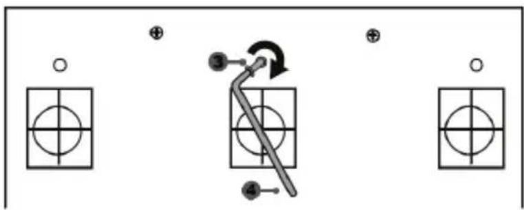
natural_image
Mechanical assembly diagram showing a valve mechanism with directional arrows (no text or labels)PRAWA AUTORSKIE
natural_image
Symbol of a trash bin with no text or labels, including a crossed-out box and a black rectangle below (no readable text or symbols)www.thrustmaster.com
natural_image
Line drawing of a steering wheel and three handheld motors on a platform (no text or symbols)PS3™SELECT/START 7 PS4™ SHARE/OPTIONS
PS 8
مُطْلَقَا
دانما
natural_image
Top-down line drawing of hands holding a steering wheel, enclosed in a circular frame (no text or symbols)T3PA THRUSTMASTER 3 PEDALS ADD-ON
natural_image
Line drawing of three identical mobile phones on a base platform (no text or symbols)الميزات التقنية
natural_image
Two identical mobile phone controllers with left-hand side indicators (no text or symbols)في اليسار
natural_image
Line drawing of two identical mobile phones with buttons and ventilation slots (no text or symbols)في المنصف (افتراضي)
flowchart
graph TD
    A["Mobile Phone 1"] --> B["Mobile Phone 2"]
    style A fill:#f9f,stroke:#333
    style B fill:#bbf,stroke:#333
في اليمين
natural_image
Diagram of a mechanical structure with a triangular frame and an arrow indicating upward motion (no text or symbols)وضعائل قليلاً
natural_image
Diagram of a mechanical structure with an arrow indicating direction, no text or symbols present
natural_image
Mechanical component diagram showing a valve mechanism with a rotating knob (no text or symbols)
natural_image
Technical line drawing of a mechanical clamp or bracket assembly (no text or symbols)natural_image
Diagram showing a hand holding a tool near an oil pumpjack, with a circular arrow indicating rotation (no text or symbols)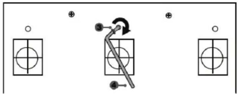
flowchart
graph TD
    A["Input"] --> B["Control Unit"]
    C["Output"] --> D["Control Unit"]
    E["Control Unit"] --> F["Control Unit"]
    G["Control Unit"] --> H["Control Unit"]
    I["Control Unit"] --> J["Control Unit"]
natural_image
Mechanical component diagram showing a valve mechanism with directional arrows (no text or symbols)حقوق النشر
www.thrustmaster.com
natural_image
Line drawing of a steering wheel and three motor drive holders on a platform (no text or symbols)WARNING:
To ensure that your T150 Force Feedback racing wheel functions correctly
with games for PlayStation®3 or PlayStation®4 systems,
you may be required to install the games' automatic updates
(available when your console is connected to the Internet).
TECHNICAL FEATURES
1 T150 Force Feedback base
2 Wheel
3 2 sequential paddle shifters (Up & Down)
4 Directional buttons
5 PS4 ^TM or PS3 ^TM USB sliding switch
6 MODE button + red/green indicator light
7 SELECT/START buttons on PS3 ^TM and SHARE/OPTIONS on PS4 ^TM
8 PS button
9 Large threaded hole (for attachment system and fastening screw)
10 Attachment system
11 Metal fastening screw
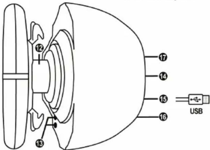
12 Steering axis
13 L3/R3 buttons
14 Power cable
or Power supply connector (type A or B) (varies from one country to another)
15 Racing wheel USB cable and connector
16 Shifter (gearbox) connector (sold separately)
17 Pedal set connector
WARNINGS
Before using this product, please read this manual carefully and save it for later reference.

Warning – Electrical shock
* Keep the product in a dry location and do not expose it to dust or sunlight.
* Do not twist or pull on the connectors and cables.
* Do not spill any liquid on the product or its connectors.
* Do not short-circuit the product.
* Never dismantle the product; do not throw it onto a fire and do not expose it to high temperatures.
* Do not use a power supply cable other than the one provided with your racing wheel.
* Do not use the power supply cable if the cable or its connectors are damaged, split or broken.
* Make sure that the power supply cable is properly plugged into an electrical outlet, and properly connected to the connector at the rear of the racing wheel's base.
* Do not open up the racing wheel: there are no user-serviceable parts inside. Any repairs must be carried out by the manufacturer, its authorized representative or a qualified technician.
* Only use attachment systems/accessories specified by the manufacturer.
* If the racing wheel is operating abnormally (if it is emitting any abnormal sounds, heat or odors), stop using it immediately, unplug the power supply cable from the electrical outlet and disconnect the other cables.
* If you will not be using the racing wheel for an extended period of time, unplug its power supply cable from the electrical outlet.
* The power outlet shall be installed near the equipment and shall be easily accessible.

Air vents
Make sure not to block any of the air vents on the racing wheel's base. For optimal ventilation, make sure to do the following:
* Position the wheel's base at least 10 cm away from any wall surfaces.
* Do not place the base in any tight spaces.
* Do not cover the base.
* Do not let any dust build up on the air vents.

For safety reasons, never use the pedal set with bare feet or while wearing only socks on your feet.
THRUSTMASTER® DISCLAIMS ALL RESPONSIBILITY IN THE EVENT OF INJURY RESULTING FROM USE OF THE PEDAL SET WITHOUT SHOES.

Warning – Injuries due to Force Feedback and repeated movements
Playing with a Force Feedback racing wheel may cause muscle or joint pain. To avoid any problems:
* Avoid lengthy gaming periods.
* Take 10 to 15 minute breaks after each hour of play.
* If you feel any fatigue or pain in your hands, wrists, arms, feet or legs, stop playing and rest for a few hours before you start playing again.

Warning – Injuries due to Force Feedback and repeated movements (continued)
* If the symptoms or pain indicated above persist when you start playing again, stop playing and consult your doctor.
* Keep out of children's reach.
* During gameplay, always leave both hands correctly positioned on the wheel without letting it go completely.
* During gameplay, never place your hands or your fingers under the pedals or anywhere near the pedal set.
* During calibration and gameplay, never place your hand or your arm through the openings in the racing wheel.
* Make sure that the racing wheel's base is properly secured, as per this manual's instructions.
HEAVY PRODUCT

Product to be handled only by users 14 years of age or older

Be careful not to drop the product on yourself or on anyone else!
ALWAYS
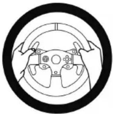
natural_image
Diagram of hands holding a steering wheel inside a circular frame (no text or symbols)NEVER

NEVER
PLAYSTATION®3 AND PLAYSTATION®4 MAPPING

PC MAPPING
SETTING UP THE RACING WHEEL FOR PLAYSTATION®3 OR PLAYSTATION®4 SYSTEMS
- Connect the pedal set to the connector (17) located at the back of the racing wheel's base.
- Plug the power supply cable (14) into an electrical outlet with the same voltage specifications.
- Set the USB sliding switch (5) on the racing wheel's base to either the PS3 ^TM or PS4 ^TM position, depending on the console or the game you are using.
- Connect the racing wheel's USB connector (15) to one of the console's USB ports.
- Once your console is powered on, your racing wheel will calibrate itself automatically.
- On PlayStation®4 system (when the USB sliding switch is set to the PS4™ position): press the racing wheel's PS button (8) and sign in to your Sony Entertainment Network account, in order to be able to use the wheel.
You are now ready to play!
Important notes:
- The USB sliding switch (5) on the racing wheel's base must always be set to the proper position (PS3 ^TM or PS4 ^TM ) before connecting the wheel's USB cable to the console. To change the sliding switch's position, disconnect the USB cable from the console and then change the position of the switch before reconnecting the USB cable to the console.
- On the PlayStation®3 system, the USB sliding switch (5) must always be set to the PS3™ position:
* The wheel is recognized in most games as a T500RS wheel.
* The wheel is functional in compatible games and in console menus.
* The "PS" function is functional on the wheel. - On the PlayStation®4 system, with the USB sliding switch (5) in the PS3™ position:
* The wheel is recognized in most games as a T500RS wheel.
* The wheel is functional in compatible games, but not in console menus.
* The "SHARE" and "PS" functions are not functional on the wheel. - On the PlayStation®4 system, with the USB sliding switch (5) in the PS4™ position:
* Don't forget to press the racing wheel's PS button (8) in order to be able to use the wheel.
* The wheel is recognized in most games as a T300 RS or T150 Force Feedback wheel.
* The wheel is functional in compatible games and in console menus.
* The "SHARE" and "PS" functions are functional on the wheel. - The list of PlayStation®3 and PlayStation®4 games compatible with the T150 Force Feedback (along with the required position for the USB sliding switch (5) according to the game being played) is available at:
http://support.thrustmaster.com (in the Racing Wheels/ T150 PRO Force Feedback section).
This list is updated regularly.
SETTING UP THE RACING WHEEL FOR PC
Important note:
On PC, the USB sliding switch (5) on the racing wheel's base must always be set to the PS3 ^TM position.
- Go to http://support.thrustmaster.com to download the drivers and the Force Feedback software for PC. Click Racing Wheels / T150 PRO Force Feedback, then select Drivers.
- Once the download is complete, launch the installation, and follow the on-screen instructions to connect the wheel's USB plug to your computer and complete the installation.
- Once the installation is complete, click Finish and restart your computer.
- Select Start / All Programs / Thrustmaster / FFB Racing Wheel / Control Panel to open the Game Controllers window.
The Game Controllers window displays the racing wheel's name T150 Force Feedback Racing Wheel with the status OK.
-
Click Properties to configure your wheel in the T150 Force Feedback control panel:
-
Test Input tab: allows to test and view the action buttons, directional buttons, wheel and pedals axes, and to adjust the wheel's rotation angle in your PC games.
- Test Forces tab: allows to test 12 force feedback effects.
- Gain Settings tab: allows to adjust the power of the force feedback effects in your PC games.
You are now ready to play!
General notes:
- On PC, click OK to close the Game Controllers window before launching the game.
- On PC, the adjustments made in the Game Controllers window will only be saved on your computer (hence they will have no effect on PlayStation®3 or PlayStation®4).
- Your wheel's firmware version is displayed in the upper right-hand corner of the T150 Force Feedback control panel tabs.
ATTACHING THE RACING WHEEL
Attaching the racing wheel to a table or a desktop
- Place the racing wheel on a table or any other horizontal, flat and stable surface.
- Insert the fastening screw (11) in the attachment system (10), then tighten the device by turning the screw counterclockwise, so that it feeds into the large threaded hole (9) located beneath the racing wheel, until the wheel is perfectly stable.
ALWAYS NEVER
natural_image
Technical line drawing of a mechanical assembly with no visible text or symbols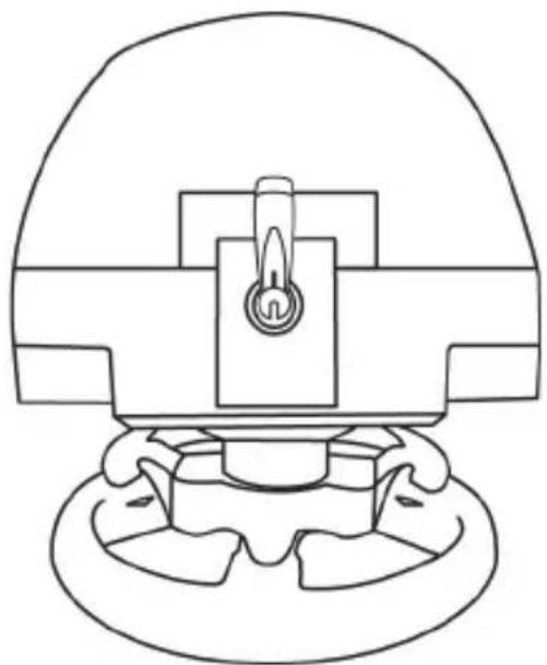
natural_image
Technical line drawing of a mechanical component with no visible text or symbolsWARNING: Never tighten the screw alone, without the attachment system in place! (This could damage the racing wheel.)
| ATTACHMENT / REMOVAL | DIRECTION |
| To tighten:Turn the screw counterclockwise | 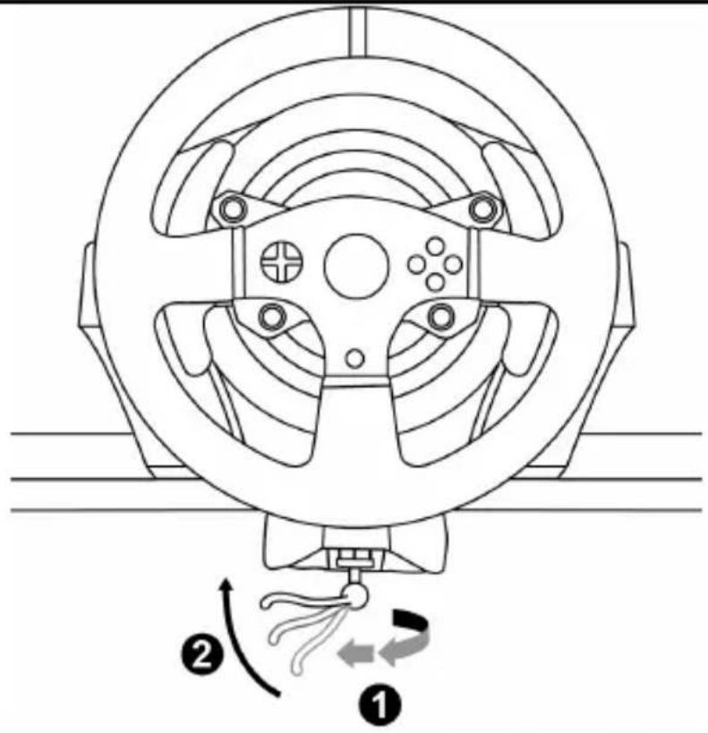 |
| To release:Turn the screw clockwise | 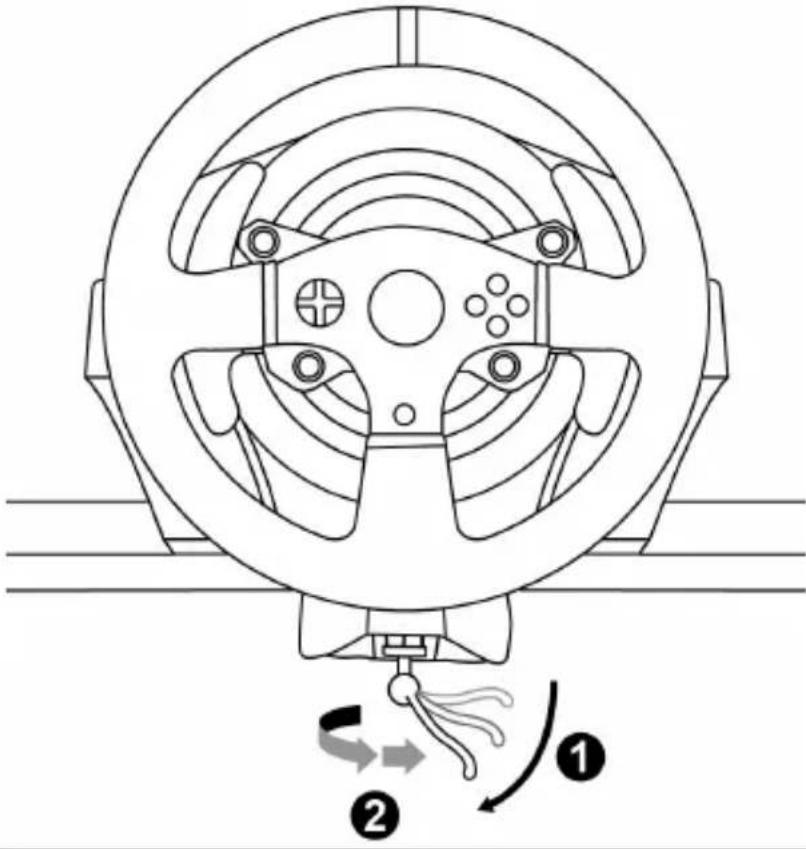 |
AUTOMATIC RACING WHEEL CALIBRATION
The wheel automatically self-calibrates when you plug the racing wheel into an electrical outlet and connect the racing wheel's USB connector to the console.
During this phase, the racing wheel will rotate quickly towards the left and the right, covering a 1080 degree angle, before stopping at the center.
WARNING: Never touch the racing wheel during the self-calibration phase!
(This could result in improper calibration and/or personal injuries.)
MODE BUTTON AND INDICATOR LIGHT (6)
MODE button for the pedal set
The MODE button allows you to electronically swap the accelerator and clutch pedals.
To do so, simply press the MODE button (6) for 2 seconds.
The racing wheel's internal memory stores whether the pedals have been swapped around or not.
| GAS AND CLUTCH PEDALS | Color of the MODE indicator light (6) |
| NORMAL | RED |
| SWAPPED AROUND | GREEN |

With the included T3PA pedal set, make sure that the indicator light remains red! (or else the gas pedal will not function properly)
Other hints regarding the MODE button
To learn more about the MODE button and indicator light, please visit http://support.thrustmaster.com. Click Racing Wheels / T150 PRO Force Feedback, and then select Manual or FAQ.
UPDATING YOUR RACING WHEEL'S FIRMWARE
The firmware included in your racing wheel's base can be updated to a more recent version featuring product enhancements.
To display the firmware version that your racing wheel is currently using and update it if required: on PC, visit http://support.thrustmaster.com. Click Racing Wheels / T150 PRO Force Feedback, then select Firmware and follow the instructions describing the download and installation procedure.
HELP FILES AND FAQs (NOT INCLUDED IN THIS MANUAL)
Please visit http://support.thrustmaster.com. Click Racing Wheels / T150 PRO Force Feedback, and then select Manual or FAQ.
If your racing wheel and/or pedal set do not function correctly, or if they seem to be improperly calibrated:
Power off your console and completely disconnect the racing wheel. Then reconnect all cables (including the power supply cable and the pedal set), and restart your console and your game.

natural_image
Line drawing of three identical electronic devices mounted on a base (no text or symbols)TECHNICAL FEATURES
1 Metal support for conical stop (not installed by default)
2 Conical stop
3 Attachment screw for metal support
4 2.5 mm Allen key (included)
5 Position adjustment nut for conical stop
6 Pedal arm
7 Plastic head support
natural_image
Simple line drawing of a door with two dots and a numbered label (6) pointing to the side, no text or symbols present.8 Metal pedal head
natural_image
Simple line drawing of a rectangular object with four circular holes and a numbered circle pointing to the top-right corner (no text or symbols)
natural_image
Line drawing of a remote control with labeled button 'B' (no text or symbols on device)WARNING

For safety reasons, never use the pedal set with bare feet or while wearing only socks on your feet.
THRUSTMASTER® DISCLAIMS ALL RESPONSIBILITY IN THE EVENT OF INJURY RESULTING FROM USE OF THE PEDAL SET WITHOUT SHOES.

Warning – Pedal set pinching hazard during gaming sessions
* Keep the pedal set out of the reach of children.
* During gaming sessions, never place your fingers or thumbs on or near the sides of the pedals.
* During gaming sessions, never place your fingers or thumbs on or near the rear base of the pedals.
* During gaming sessions, never place your fingers or thumbs on or near the front base of the pedals.
AUTOMATIC CALIBRATION OF PEDALS

- Never connect or disconnect the pedal set from the base of the wheel when the wheel is connected to the console or PC, or during gaming sessions, to avoid calibration problems.
= Always connect the pedal set to the wheel before connecting the wheel to the console or PC. - Once the wheel has self-calibrated and the game has started, the pedals automatically calibrate themselves after being pressed a few times.
- Never press on the pedals when the wheel is self-calibrating or when your game is starting up, to avoid calibration problems.
- If the pedals are not functioning correctly or appear to be improperly calibrated, power off your console, completely disconnect your wheel, then reconnect all of the cables (including the power supply cable and the pedal set cable), power the console back on and restart your game.
ATTACHING THE PEDAL SET TO A COCKPIT
- Attach the pedal set using the small screw threads located on the underside of the pedal set.
- Screw two M6 screws (not included) into the cockpit's pedal support plate and into the two small screw threads located on the underside of the pedal set.
Important: The length of the two M6 screws must not exceed the thickness of the cockpit's pedal support plate plus an additional 10 mm, to avoid damaging the pedal set's internal components.
Layout diagrams for cockpits (for positioning the racing wheel's base and/or the pedal set) are available at: click Wheels / T150 PRO Force Feedback, then select Manual or FAQ.
ADJUSTING THE PEDAL SET
Each of the three pedals includes:
- A metal head (8) with multiple perforations (nine for the accelerator – six for the brake – six for the clutch).
- A plastic head support (7) (placed between the head and the arm) with four perforations.
- A pedal arm (6) with two perforations.
ATTENTION: To avoid any calibration problems, be sure to always disconnect your wheel's USB cable from the console or PC before making any adjustments to your pedal set.
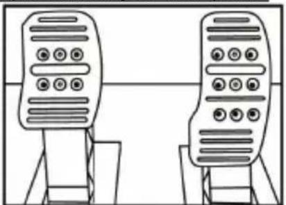
Adjusting the HEIGHT of the accelerator pedal
- Using the included 2.5 mm Allen key (4), unscrew the two screws holding the metal head (8) and its support (7) in place.
- Select your preferred height position, then replace and re-tighten the screws so that the metal head (8) and its support (7) are held firmly in place.
natural_image
Diagram showing two identical devices with circular buttons on top, connected by a downward arrow (no text or symbols)Low position (default)
natural_image
Two identical mobile phone screens with buttons and a bidirectional arrow between them (no text or symbols)High position
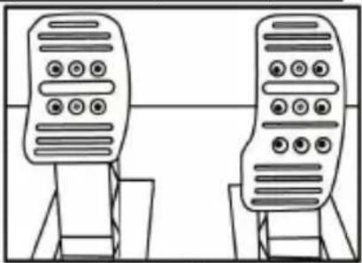
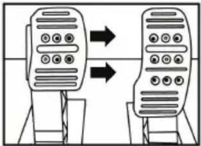
Adjusting the SPACING of the three pedals
- Using the included 2.5 mm Allen key (4), unscrew the two screws holding the metal head (8) and its support (7) in place.
- Select your preferred position (to the left, centered, or to the right), then replace and re-tighten the screws so that the metal head (8) and its support (7) are held firmly in place.
Examples illustrating the brake pedal:
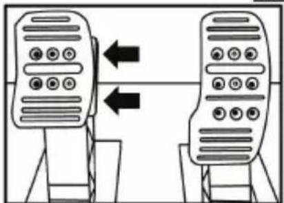
natural_image
Two identical mobile phone controllers with left-hand side arrows indicating bidirectional connection (no text or symbols)Left position
natural_image
Line drawing of two identical mobile phones on stands, no text or symbols presentCentered position (default)
flowchart
graph TD
    A["Mobile Device 1"] --> B["Mobile Device 2"]
    style A fill:#f9f,stroke:#333
    style B fill:#bbf,stroke:#333
Right position
Number of possible spacing positions per pedal:
- Three for accelerator pedal
- Three for brake pedal
- Three for clutch pedal
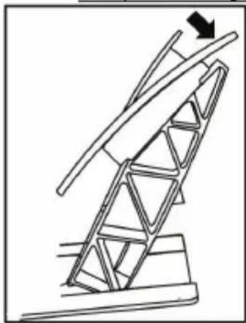
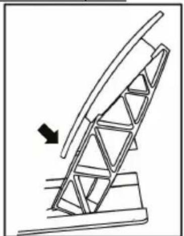
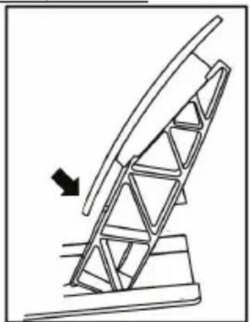
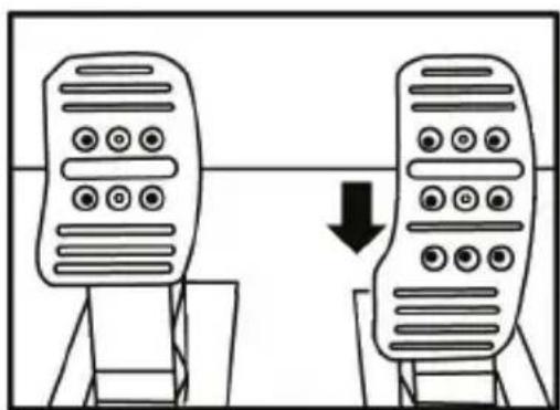
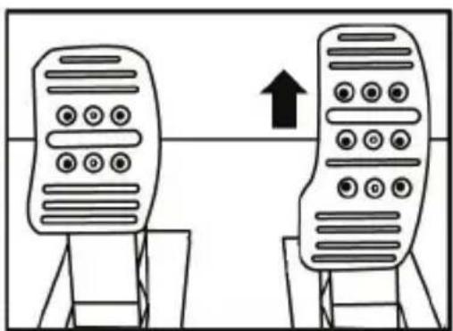
Adjusting the INCLINATION of the pedals
- Using the included 2.5 mm Allen key (4), unscrew the two screws holding the metal head (8) and its support (7) in place.
- Turn the plastic head support (7) 180°, then replace and re-tighten the screws so that the metal head (8) and its support (7) are held firmly in place.
Examples illustrating the accelerator pedal:
natural_image
Diagram of a mechanical structure with triangular supports and a directional arrow (no text or symbols)Less inclined position
natural_image
Diagram of a mechanical structure with an arrow indicating direction, no text or symbols presentMore inclined position (default)
Number of possible inclination positions per pedal:
- Two for accelerator pedal
- Two for brake pedal
- Two for clutch pedal
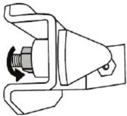
Installing the conical stop ("CONICAL RUBBER BRAKE" mod)
This modification (or "mod") is not essential, and is not installed by default. This means that the brake pedal functions perfectly even if the mod is not installed.
This mod lets you experience a different feeling and resistance when braking. It's up to you whether or not to install it, depending on your own preferences.
- Screw the conical stop (2) onto its metal support (1).
- Screw the position adjustment nut (5) onto the bottom (onto the conical stop's screw thread).
- Position the unit at the back of the brake pedal's arm.
- Using the included 2.5 mm Allen key (4), attach the unit using the attachment screw (3) and the small central screw thread located on the underside of the pedal set.
natural_image
Diagram showing a hand holding a tool inside a circular frame with an arrow indicating rotation (no text or symbols)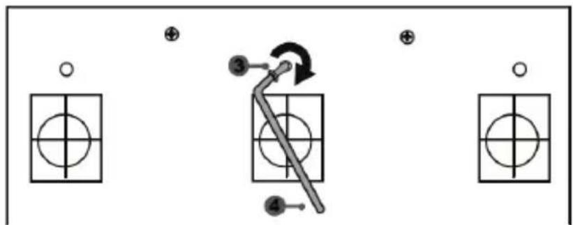
flowchart
graph TD
    A["Step 1: Circle with cross"] --> B["Step 2: Arrow with arrow"]
    B --> C["Step 3: Arrow with arrow"]
    C --> D["Step 4: Arrow with arrow"]
The "CONICAL RUBBER BRAKE" mod is now installed!
Adjusting the brake pedal's RANGE of travel and STRENGTH of resistance
By slightly unscrewing the nut (5), you can further strengthen the resistance of the brake pedal by moving the conical stop (2) closer to the back of the pedal's arm (if necessary, use a 14 mm wrench or pliers to re-tighten the nut and maintain the selected position). The closer the conical stop is positioned to the back of the pedal's arm, the greater the strength of resistance will be.
natural_image
Mechanical assembly diagram showing a valve mechanism with directional arrows (no text or labels)Note: When the conical stop is very close to the back of the brake pedal's arm, you may experience difficulties in reaching the maximum calibration value. Should that be the case:
* Slowly, press very hard on the brake pedal so as to reach the maximum value (if necessary, stand very briefly on the pedal – just for a second), then release the pressure; or else
* Move the conical stop a bit farther away from the back of the brake pedal's arm.
Consumer warranty information
Worldwide, Guillemot Corporation S.A., whose registered office is located at Place du Granier, B.P. 97143, 35571 Chantepie, France (hereinafter "Guillemot") warrants to the consumer that this Thrustmaster product shall be free from defects in materials and workmanship, for a warranty period which corresponds to the time limit to bring an action for conformity with respect to this product. In the countries of the European Union, this corresponds to a period of two (2) years from delivery of the Thrustmaster product. In other countries, the warranty period corresponds to the time limit to bring an action for conformity with respect to the Thrustmaster product according to applicable laws of the country in which the consumer was domiciled on the date of purchase of the Thrustmaster product (if no such action exists in the corresponding country, then the warranty period shall be one (1) year from the original date of purchase of the Thrustmaster product).
Notwithstanding the above, rechargeable batteries are covered by a warranty period of six (6) months from the date of original purchase.
Should the product appear to be defective during the warranty period, immediately contact Technical Support, who will indicate the procedure to follow. If the defect is confirmed, the product must be returned to its place of purchase (or any other location indicated by Technical Support).
Within the context of this warranty, the consumer's defective product shall, at Technical Support's option, be either replaced or returned to working order. If, during the warranty period, the Thrustmaster product is subject to such reconditioning, any period of at least seven (7) days during which the product is out of use shall be added to the remaining warranty period (this period runs from the date of the consumer's request for intervention or from the date on which the product in question is made available for reconditioning, if the date on which the product is made available for reconditioning is subsequent to the date of the request for intervention). If permitted under applicable law, the full liability of Guillemot and its subsidiaries (including for consequential damages) is limited to the return to working order or the replacement of the Thrustmaster product. If permitted under applicable law, Guillemot disclaims all warranties of merchantability or fitness for a particular purpose.
This warranty shall not apply: (1) if the product has been modified, opened, altered, or has suffered damage as a result of inappropriate or abusive use, negligence, an accident, normal wear, or any other cause unrelated to a material or manufacturing defect (including, but not limited to, combining the Thrustmaster product with any unsuitable element, including in particular power supplies, rechargeable batteries, chargers, or any other elements not supplied by Guillemot for this product); (2) if the product has been used for any use other than home use, including for professional or commercial purposes (game rooms, training, competitions, for example); (3) in the event of failure to comply with the instructions provided by Technical Support; (4) to software, said software being subject to a specific warranty; (5) to consumables (elements to be replaced over the product's lifespan: disposable batteries, audio headset or headphone ear pads, for example); (6) to accessories (cables, cases, pouches, bags, wrist-straps, for example); (7) if the product was sold at public auction.
This warranty is nontransferable.
The consumer's legal rights with respect to laws applicable to the sale of consumer goods in his or her country are not affected by this warranty.
Additional warranty provisions
During the warranty period, Guillemot shall not provide, in principle, any spare parts, as Technical Support is the only party authorized to open and/or recondition any Thrustmaster product (with the exception of any reconditioning procedures which Technical Support may request that the consumer carry out, by way of written instructions – for example, due to the simplicity and the lack of confidentiality of the reconditioning process – and by providing the consumer with the required spare part(s), where applicable).
Given its innovation cycles and in order to protect its know-how and trade secrets, Guillemot shall not provide, in principle, any reconditioning notification or spare parts for any Thrustmaster product whose warranty period has expired.
In the United States of America and in Canada, this warranty is limited to the product's internal mechanism and external housing. In no event shall Guillemot or its affiliates be held liable to any third party for any consequential or incidental damages resulting from the breach of any express or implied warranties. Some States/Provinces do not allow limitation on how long an implied warranty lasts or exclusion or limitation of liability for consequential or incidental damages, so the above limitations or exclusions may not apply to you. This warranty gives you specific legal rights, and you may also have other rights which vary from State to State or Province to Province.
Liability
If permitted under applicable law, Guillemot Corporation S.A. (hereinafter "Guillemot") and its subsidiaries disclaim all liability for any damages caused by one or more of the following: (1) the product has been modified, opened or altered; (2) failure to comply with assembly instructions; (3) inappropriate or abusive use, negligence, an accident (an impact, for example); (4) normal wear; (5) the use of the product for any use other than home use, including for professional or commercial purposes (game rooms, training, competitions, for example). If permitted under applicable law, Guillemot and its subsidiaries disclaim all liability for any damages unrelated to a material or manufacturing defect with respect to the product (including, but not limited to, any damages caused directly or indirectly by any software, or by combining the Thrustmaster product with any unsuitable element, including in particular power supplies, rechargeable batteries, chargers, or any other elements not supplied by Guillemot for this product).
FCC STATEMENT
- This device complies with Part 15 of the FCC Rules. Operation is subject to the following two conditions:
(1) This device may not cause harmful interference, and
(2) This device must accept any interference received, including interference that may cause undesired operation.
- Changes or modifications not expressly approved by the party responsible for compliance could void the user's authority to operate the equipment.
DECLARATION OF CONFORMITY
CANADIAN COMPLIANCE NOTICE: this Class B digital apparatus meets all requirements of the Canadian Interference-Causing Equipment Regulations.
USA COMPLIANCE NOTICE: this equipment has been tested and found to comply with the limits for a Class B digital device, pursuant to Part 15 of the FCC rules. Operation is subject to the following two conditions:
(1) This device may not cause harmful interference, and
(2) This device must accept any interference received, including interference that may cause undesired operation.
These limits are designed to provide reasonable protection against harmful interference in a residential installation. This equipment generates, uses and can radiate radio frequency energy and, if not installed and used in accordance with the instructions, may cause harmful interference to radio communications. However, there is no guarantee that interference will not occur in a particular installation. If this equipment does cause harmful interference to radio or television reception, which can be determined by turning the equipment on and off, the user is encouraged to try to correct the interference by one or more of the following measures:
- Reorient or relocate the receiving antenna.
- Increase the separation between the equipment and receiver.
- Connect the equipment into an outlet on a circuit different from that to which the receiver is connected.
- Consult the dealer or an experienced radio/TV technician for help.
COPYRIGHT
© 2017 Guillemot Corporation S.A. All rights reserved. Thrustmaster® is a registered trademark of Guillemot Corporation S.A. Manufactured & distributed under license by Sony Interactive Entertainment America LLC.
Playstation, the PS family logo, PS3, PS4 and “△OX□” are registered trademarks of Sony Interactive Entertainment. All rights reserved. All other trademarks and brand names are hereby acknowledged and are property of their respective owners. Illustrations not binding. Contents, designs and specifications are subject to change without notice and may vary from one country to another. Made in China.
ENVIRONMENTAL PROTECTION RECOMMENDATION
Please adhere to local recycling laws for electrical and electronic equipment.
Retain this information. Colors and decorations may vary.
Plastic fasteners and adhesives should be removed from the product before it is used.
www.thrustmaster.com


THRUSTMASTER®
TECHNICAL SUPPORT
http://support.thrustmaster.com


T150 PRO
FORCE FEEDBACK / RETOUR DE FORCE
POUR SYSTÈMES P LAYSTATION®3 – PLAYSTATION®4
natural_image
Line drawing of a steering wheel and three motor drive holders on a platform (no text or symbols)ATTENTION :
natural_image
Diagram of hands holding a steering wheel, enclosed in a circular frame (no text or symbols)

CORRESPONDANCES PLAYSTATION®3 ET PLAYSTATION®4
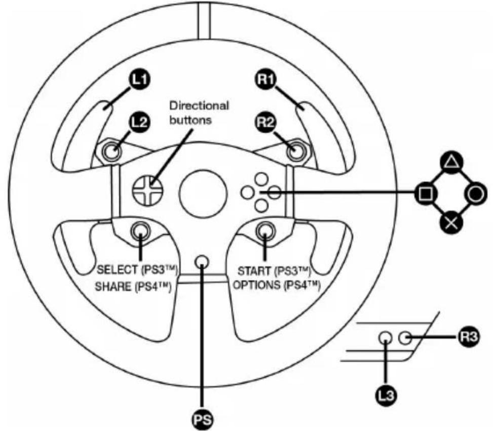
CORRESPONDANCES PC
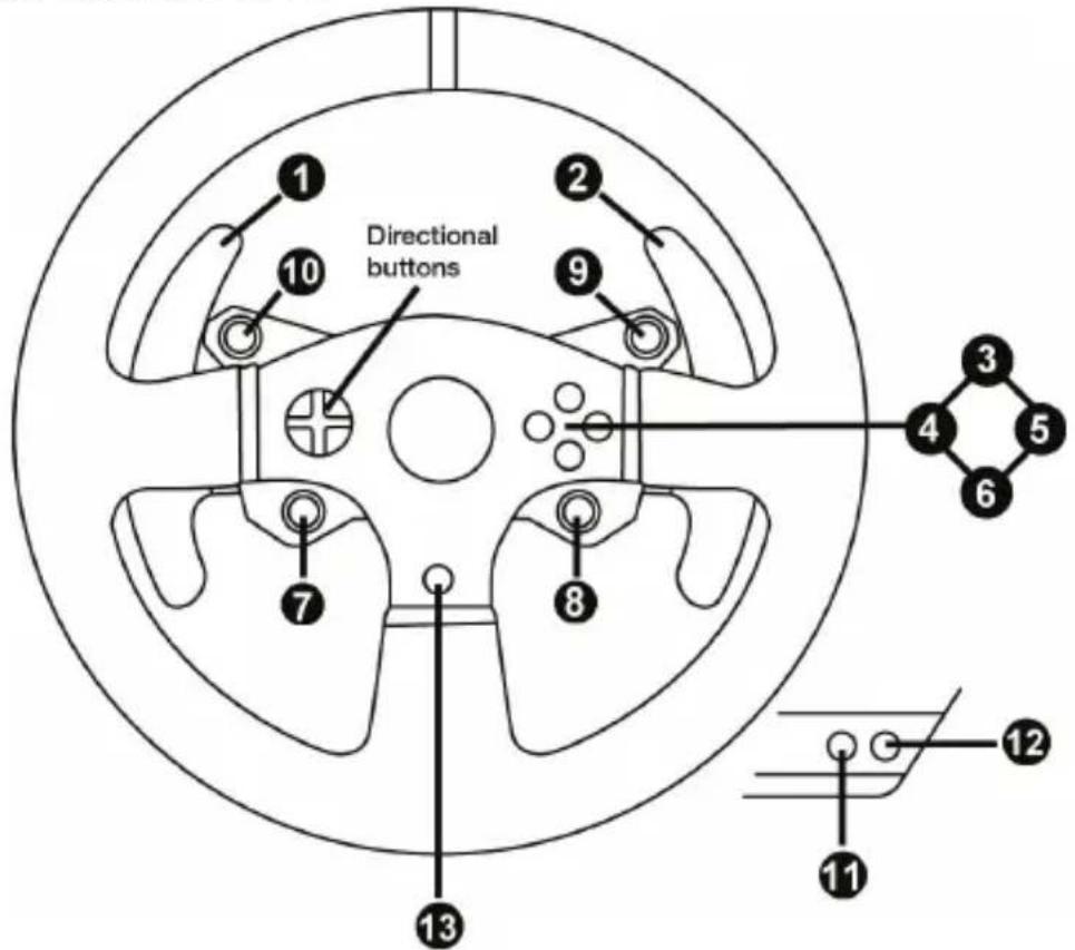
INSTALLATION SUR SYSTÈMES PLAYSTATION®3 OU PLAYSTATION®4
natural_image
Technical line drawing of a mechanical assembly with no visible text or symbols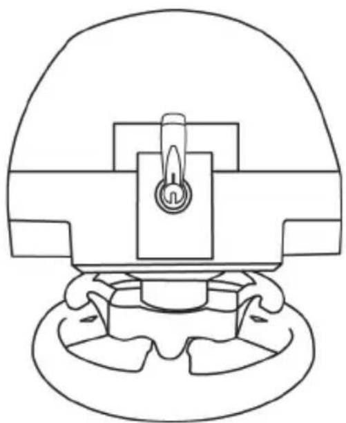
natural_image
Technical line drawing of a mechanical component with no visible text or symbols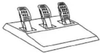
natural_image
Line drawing of three identical electronic devices mounted on a base (no text or symbols)CARACTERISTIQUES TECHNIQUES
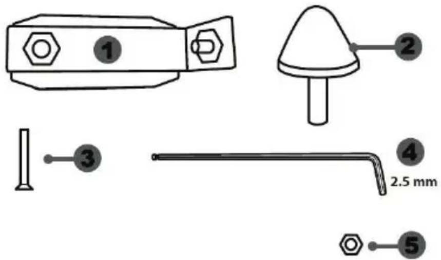
natural_image
Simple line drawing of a refrigerator with two dots on the door (no text or symbols)natural_image
Simple diagram of a rectangular device with five circular ports and a numbered label '7' pointing to one port (no text or symbols beyond the number)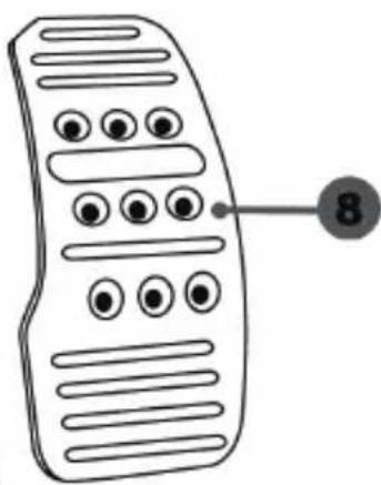
natural_image
Line drawing of a remote control with labeled buttons (no text or symbols beyond the number 8)AVERTISSEMENT

natural_image
Diagram showing two identical devices with circular buttons on top, connected by a downward arrow (no text or symbols)natural_image
Two identical mobile phone screens with circular buttons on stands, connected by an upward arrow (no text or symbols)Position haute
natural_image
Diagram showing two identical devices with bidirectional arrows indicating interaction (no text or symbols)Position à gauche
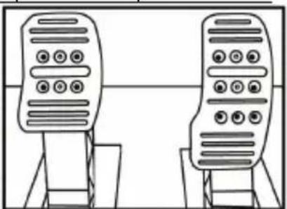
natural_image
Line drawing of two identical mobile phones with buttons on stands (no text or symbols)natural_image
Diagram of a ladder structure with an arrow indicating upward motion (no text or symbols)natural_image
Diagram of a mechanical structure with an arrow indicating direction, no text or symbols present
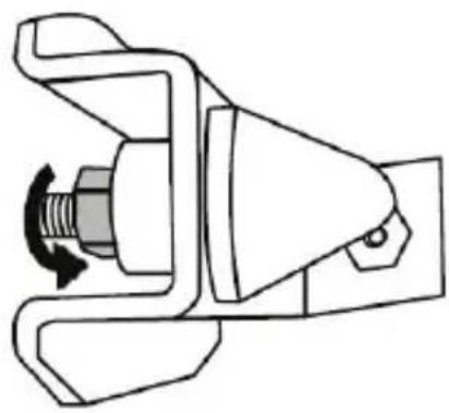
natural_image
Mechanical component diagram showing a valve mechanism with a rotating knob (no text or symbols)natural_image
Illustration of an oil pump with a hand holding a tool, showing a circular motion arrow (no text or symbols)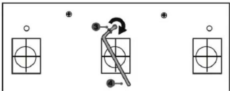
flowchart
graph TD
    A["Input"] --> B["Step 1: Circle with cross"]
    B --> C["Step 2: Arrow with arrow indicating rotation"]
    C --> D["Step 3: Arrow with circle inside grid"]
    D --> E["Step 4: Arrow with circle inside grid"]
    E --> F["Output"]
natural_image
Mechanical assembly diagram showing a valve mechanism with directional arrows (no text or labels)www.thrustmaster.com


REJOIGNEZ LA
THRUSTMASTER®
RACING TEAM
POUR AMATEURS DE
SIMULATION AUTOMOBILE

THRUSTMASTER®
SUPPORT TECHNIQUE
http://support.thrustmaster.com


T150 PRO
FORCE FEEDBACK / RETOUR DE FORCE
PARA SISTEMAS PLAYSTATION®3 – PLAYSTATION®4
Manual del usuario
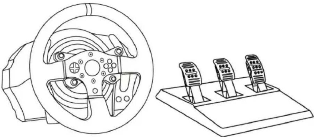
natural_image
Line drawing of a steering wheel and three motor drive holders on a platform (no text or symbols)ADVERTENCIA:
natural_image
Diagram of hands holding a steering wheel with no text or symbolsNUNCA
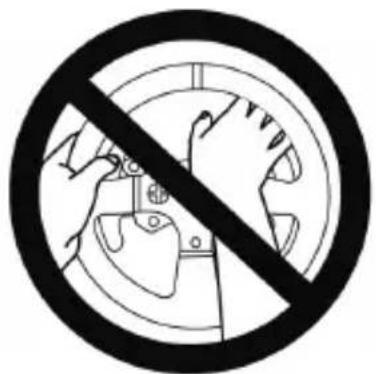
NUNCA

ASIGNACIÓN PARA PLAYSTATION®3 AND PLAYSTATION®4
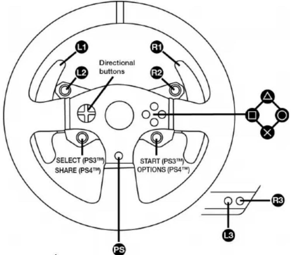
ASIGNACIÓN PARA PC
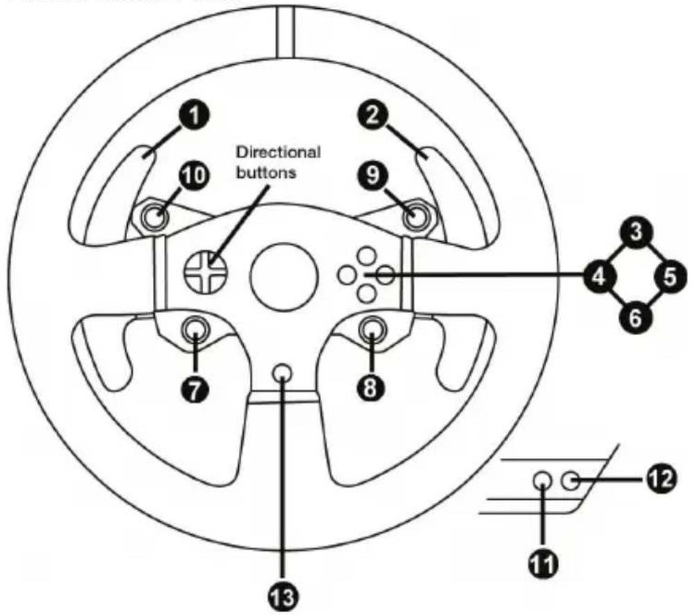
natural_image
Technical line drawing of a mechanical assembly with no visible text or symbols
natural_image
Technical line drawing of a mechanical component with no visible text or symbols
natural_image
Line drawing of three identical electronic devices mounted on a base (no text or symbols)CARACTERÍSTICAS TÉCNICAS
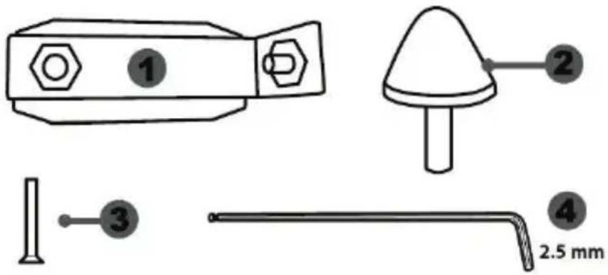

natural_image
Simple line drawing of a door with two dots and a numbered label (6) pointing to the side, no text or symbols present.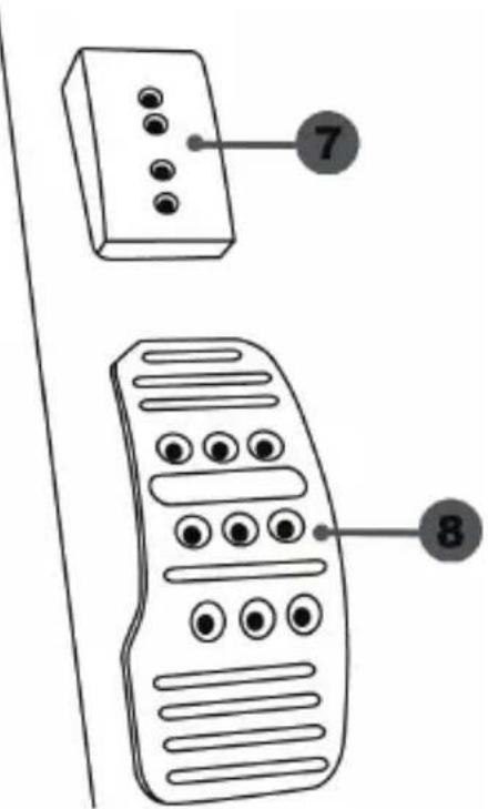
natural_image
Diagram showing two identical mobile devices connected by a double-headed arrow (no text or symbols)natural_image
Two identical mobile phone controllers with buttons and a bidirectional arrow between them (no text or symbols)Posición alta
natural_image
Two identical mobile phone controllers with bidirectional arrows indicating signal or connection (no text or symbols)Posición izquierda
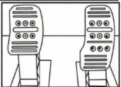
natural_image
Line drawing of two identical mobile phones on stands, no text or symbols presentnatural_image
Diagram of a ladder structure with an arrow indicating upward motion (no text or symbols)natural_image
Diagram of a mechanical structure with an arrow indicating direction, no text or symbols presentnatural_image
Illustration of an oil pumpjack inside a circular frame, with a hand holding a tool and a black arrow indicating rotation (no text or symbols)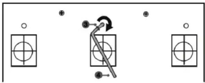
flowchart
graph TD
    A["Step ③"] --> B["Arrow to Line"]
    B --> C["Step ④"]
    C --> D["Step ④"]
    D --> E["Step ④"]
    E --> F["Step ④"]
    F --> G["Step ④"]
    G --> H["Step ④"]
    H --> I["Step ④"]
    I --> J["Step ④"]
    J --> K["Step ④"]
    K --> L["Step ④"]
    L --> M["Step ④"]
    M --> N["Step ④"]
    N --> O["Step ④"]
    O --> P["Step ④"]
    P --> Q["Step ④"]
    Q --> R["Step ④"]
    R --> S["Step ④"]
    S --> T["Step ④"]
    T --> U["Step ④"]
    U --> V["Step ④"]
    V --> W["Step ④"]
    W --> X["Step ④"]
    X --> Y["Step ④"]
    Y --> Z["Step ④"]
    Z --> AA["Step ④"]
    AA --> AB["Step ④"]
    AB --> AC["Step ④"]
    AC --> AD["Step ④"]
    AD --> AE["Step ④"]
    AE --> AF["Step ④"]
    AF --> AG["Step ④"]
    AG --> AH["Step ④"]
    AH --> AI["Step ④"]
    AI --> AJ["Step ④"]
    AJ --> AK["Step ④"]
    AK --> AL["Step ④"]
    AL --> AM["Step ④"]
    AM --> AN["Step ④"]
    AN --> AO["Step ④"]
    AO --> AP["Step ④"]
    AP --> AQ["Step ④"]
    AQ --> AR["Step ④"]
    AR --> AS["Step ④"]
    AS --> AT["Step ④"]
    AT --> AU["Step ④"]
    AU --> AV["Step ④"]
    AV --> AW["Step ④"]
    AW --> AX["Step ④"]
    AX --> AY["Step ④"]
natural_image
Mechanical component diagram showing a valve mechanism with directional arrows (no text or labels)www.thrustmaster.com


T150
FORCE FEEDBACK
PARA SISTEMAS PLAYSTATION®3 – PLAYSTATION®4
Manual do Usuário
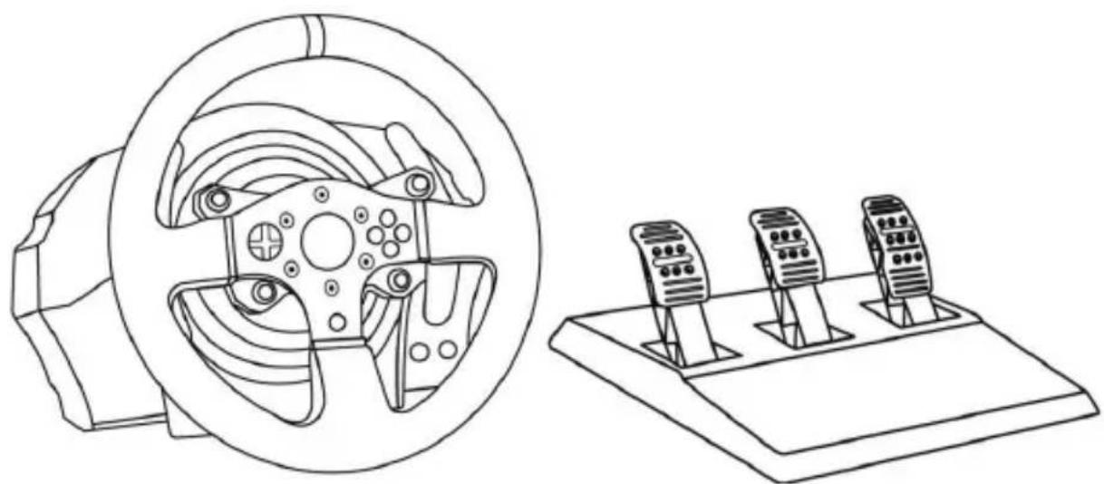
natural_image
Line drawing of a steering wheel and three motor drive holders on a platform (no text or symbols)ATENÇÃO:
1 Base
2 Volante
3 2 borboletas de mudança de marchas sequenciais (Up e Down)
4 D-Pad multidirecional
5 Seletor USB PS4 ^TM ou PS3 ^TM
6 Botão MODE + luz indicadora vermelha/verde
natural_image
Diagram of hands holding a steering wheel with no text or symbolsNUNCA

NUNCA
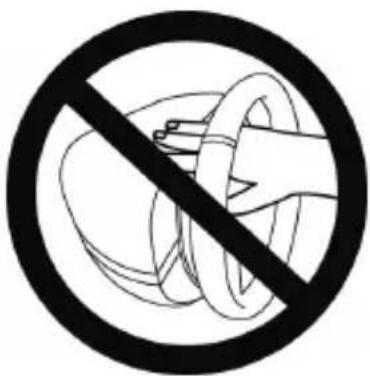
MAPEAMENTO NO PLAYSTATION®3 E PLAYSTATION®4
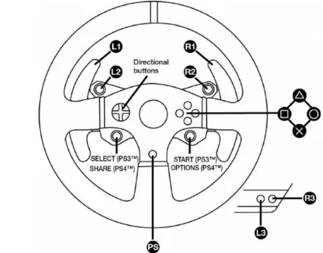
MAPEAMENTO PARA PC
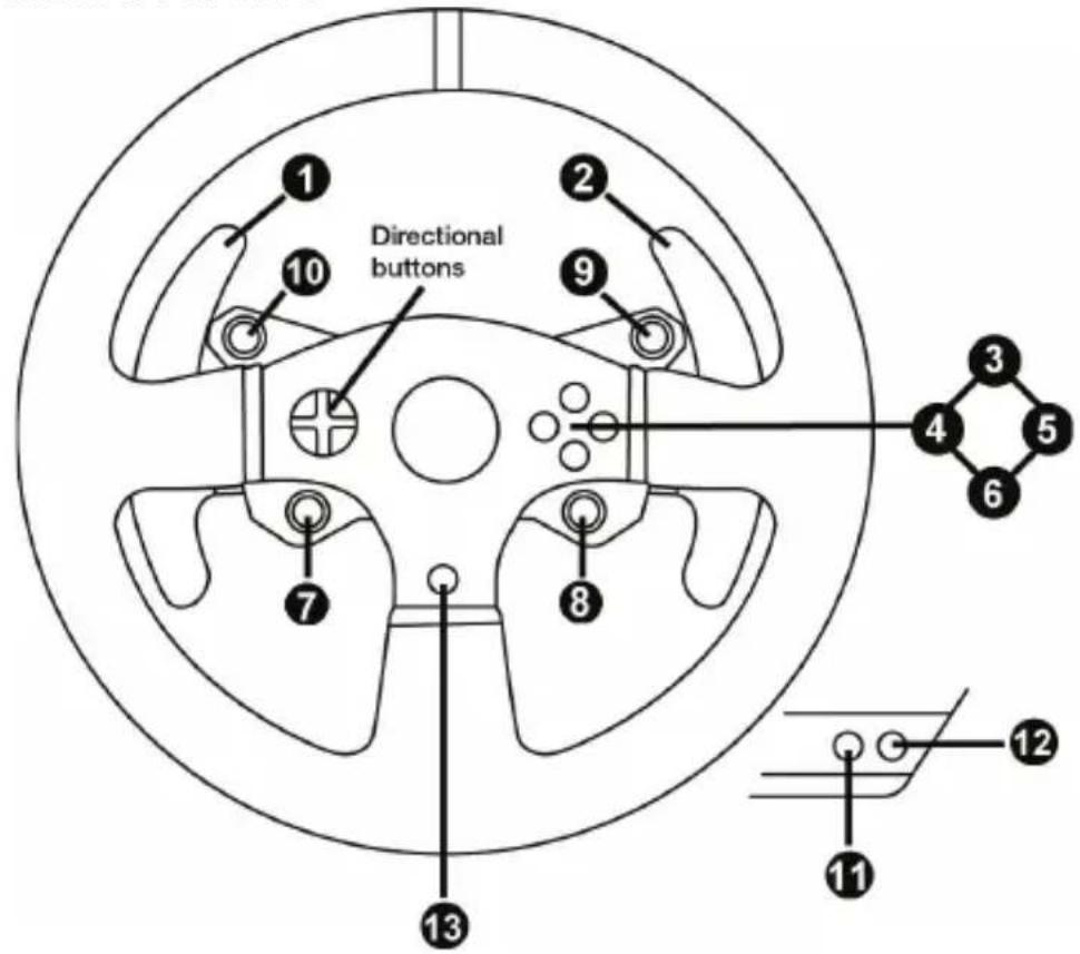
CONFIGURAR O VOLANTE PARA OS SISTEMAS PLAYSTATION®3 OU PLAYSTATION®4
natural_image
Technical line drawing of a mechanical assembly with no visible text or symbols
natural_image
Technical line drawing of a mechanical component with no visible text or symbols
natural_image
Line drawing of three identical electronic devices mounted on a base (no text or symbols)CARACTERÍSTICAS TÉCNICAS
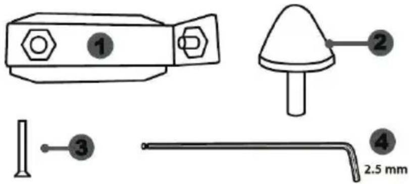
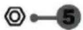
natural_image
Simple line drawing of a door with two dots and a numbered label (6), no text or symbols present.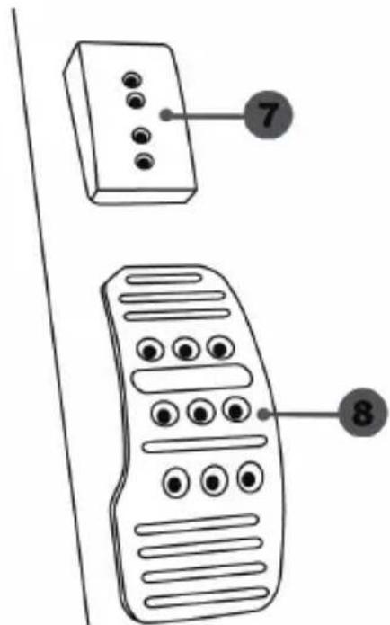
CALIBRAGEM AUTOMÁTICA DOS PEDAIS

FIXAR O CONJUNTO DE PEDAIS A UM COCKPIT
- Fixe o conjunto de pedais utilizando as pequenas roscas de parafusos situadas na parte inferior do conjunto de pedais.
- Enrosque dois parafusos M6 (não incluídos) na chapa de apoio do conjunto de pedais e nas duas pequenas roscas de parafusos situadas na parte inferior do conjunto de pedais.
natural_image
Two identical mobile phone controllers with buttons and a downward arrow indicating interaction (no text or symbols)natural_image
Two identical mobile phone icons on stands connected by a line, with an upward arrow indicating connection (no text or symbols present)Posição alta
natural_image
Two identical mobile phone controllers with bidirectional arrows indicating signal or connection (no text or symbols)Posição à esquerda
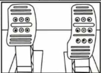
natural_image
Line drawing of two identical mobile phone devices standing upright, no text or symbols presentnatural_image
Diagram of a mechanical structure with a triangular frame and an arrow indicating upward motion (no text or symbols)natural_image
Diagram of a mechanical structure with an arrow indicating direction, no text or symbols presentnatural_image
Illustration of an oil pumpjack inside a circular frame with a hand holding a tool, no text or symbols present.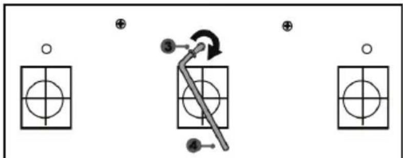
flowchart
graph TD
    A["Step 1: Circle with cross"] --> B["Step 2: Arrow with arrow"]
    B --> C["Step 3: Arrow with circle"]
    C --> D["Step 4: Arrow with circle"]
    style A fill:#fff,stroke:#000
    style B fill:#fff,stroke:#000
    style C fill:#fff,stroke:#000
    style D fill:#fff,stroke:#000
natural_image
Mechanical component diagram showing a valve mechanism with directional arrows (no text or labels)www.thrustmaster.com